Strategy for Universal Access to Health and Universal ... - PAHO
Upload
khangminh22Category
view
2download
0
MX10016 Universal Routing PlatformHardware Guide
Published
2022-06-20

Juniper Networks, Inc.1133 Innovation WaySunnyvale, California 94089USA408-745-2000www.juniper.net
Juniper Networks, the Juniper Networks logo, Juniper, and Junos are registered trademarks of Juniper Networks, Inc.in the United States and other countries. All other trademarks, service marks, registered marks, or registered servicemarks are the property of their respective owners.
Juniper Networks assumes no responsibility for any inaccuracies in this document. Juniper Networks reserves the rightto change, modify, transfer, or otherwise revise this publication without notice.
MX10016 Universal Routing Platform Hardware GuideCopyright © 2022 Juniper Networks, Inc. All rights reserved.
The information in this document is current as of the date on the title page.
YEAR 2000 NOTICE
Juniper Networks hardware and software products are Year 2000 compliant. Junos OS has no known time-relatedlimitations through the year 2038. However, the NTP application is known to have some difficulty in the year 2036.
END USER LICENSE AGREEMENT
The Juniper Networks product that is the subject of this technical documentation consists of (or is intended for usewith) Juniper Networks software. Use of such software is subject to the terms and conditions of the End User LicenseAgreement ("EULA") posted at https://support.juniper.net/support/eula/. By downloading, installing or using suchsoftware, you agree to the terms and conditions of that EULA.
ii

Table of Contents
About This Guide | x
1 Overview
MX10016 System Overview | 2
MX10016 Hardware Overview | 2
MX10016 Components and Configurations | 14
MX10016 Component Redundancy | 18
MX10016 Hardware and CLI Terminology Mapping | 19
MX10016 Chassis | 21
MX10016 Chassis Physical Specifications | 22
MX10016 Field-Replaceable Units | 25
MX10016 Status Panel LEDs | 26
MX10016 Optional Equipment | 30
MX10016 Cooling System | 33
MX10016 Cooling System and Airflow | 33
MX10016 Fan Tray LEDs and Fan Tray Controller LEDs | 43
MX10016 Power System | 50
JNP10K-PWR-AC Power Supply | 51
JNP10K-PWR-AC2 Power Supply | 54
JNP10K-PWR-DC Power Supply | 56
JNP10K-PWR-DC2 Power Supply | 59
JNP10K-PWR-AC Power Supply LEDs | 62
JNP10K-PWR-AC2 Power Supply LEDs | 64
JNP10K-PWR-DC Power Supply LEDs | 66
JNP10K-PWR-DC2 Power Supply LEDs | 68
iii
MX10016 Routing and Control Board | 71
MX10016 Routing and Control Board Description | 72
MX10016 Routing and Control Board LEDs | 74
MX10016 Switch Fabric Board | 77
MX10016 Switch Fabric Board Description | 79
Switch Fabric Board LEDs | 82
MX10K-LC2101 Line Card | 83
MX10K-LC480 Line Card | 85
2 Site Planning, Preparation, and Specifications
MX10016 Site Preparation Overview | 91
Site Preparation Checklist | 91
Environmental Requirements and Specifications | 93
General Site Guidelines | 94
Site Electrical Wiring Guidelines | 94
MX10016 Rack Requirements | 96
Depth Clearance Requirements for Airflow and Hardware Maintenance for an MX10016 | 98
MX10016 Power Planning | 100
Power Requirements for MX10016 Components | 100
Calculating Power Requirements for an MX10016 | 102
How to Calculate the Power Consumption of Your MX10016 Configuration | 102
How to Calculate the Number of Power Supplies Required for Your MX10016Configuration | 105
JNP10K-PWR-AC Power Specifications | 108
JNP10K-PWR-AC2 Power Specifications | 109
MX10016 Power Cord Specifications | 110
JNP10K-PWR-DC Power Specifications | 119
JNP10K-PWR-DC2 Power Specifications | 120
iv

MX10016 Grounding Cable and Lug Specifications | 121
MX10016 Transceiver and Cable Specifications | 122
Optical Transceiver and Cable Support | 122
Cable Specifications for Console and Management Connections | 123
Understanding Fiber-Optic Cable Signal Loss, Attenuation, and Dispersion | 124
Calculating the Fiber-Optic Cable Power Budget for an MX10016 | 126
Calculating the Fiber-Optic Cable Power Margin for an MX10016 | 126
MX10016 Alarm and Management Cable Specifications and Pinouts | 128
Console Port Connector Pinouts for an MX10016 Router | 128
USB Port Specifications for an MX10016 | 130
Management Port Connector Pinouts for an MX10016 | 130
3 Initial Installation and Configuration
MX10016 Installation Overview | 133
Unpacking an MX10016 Router and Components | 134
Unpacking an MX10016 | 134
Unpacking Line Cards, Routing and Control Boards, and Switch Fabric Boards | 137
Comparing the MX10016 Order to the Packing List | 138
Register Products—Mandatory to Validate SLAs | 143
Installing the Mounting Hardware | 144
Installing an MX10016 into a Four-Post Rack | 146
Mounting an MX10016 in a Four-Post Rack Using a Mechanical Lift | 146
Installing the Front Door on an MX10016 | 150
Before You Begin | 150
Install the Front Door | 151
Install the Air Filter in the MX100016 | 155
Connecting an MX10016 to Power | 159
Connect an MX10016 to Earth Ground | 159
v

Connecting AC Power to an MX10016 | 161
Connecting DC Power to an MX10016 | 162
Connecting an MX10016 to External Devices | 163
Connecting an MX10016 to a Network for Out-of-Band Management | 163
Connecting an MX10016 Router to a Management Console | 164
Configuring an MX10016 Router | 165
4 Maintaining Components
Field-Replaceable Units in an MX10016 | 170
Removing and Installing Routing and Control Boards | 172
How to Handle and Store an MX10016 Routing and Control Board | 172
Handling Routing and Control Boards | 172
Storing RCBs | 173
Removing a Routing and Control Board | 174
Installing a Routing and Control Board | 176
Removing and Installing MX10016 Cooling System Components | 178
Removing an MX10016 Fan Tray | 179
Installing an MX10016 Fan Tray | 182
Removing an MX10016 Fan Tray Controller | 184
Installing an MX10016 Fan Tray Controller | 186
Removing and Installing MX10016 Power System Components | 188
How to Remove a JNP10K-PWR-AC Power Supply | 188
How to Install a JNP10K-PWR-AC Power Supply | 191
How to Remove a JNP10K-PWR-AC2 Power Supply | 196
How to Install a JNP10K-PWR-AC2 Power Supply | 200
How to Remove a JNP10K-PWR-DC Power Supply | 204
How to Install a JNP10K-PWR-DC Power Supply | 207
How to Remove a JNP10K-PWR-DC2 Power Supply | 216
vi
How to Install a JNP10K-PWR-DC2 Power Supply | 219
Removing and Installing MX10016 Switch Fabric Boards | 229
How to Handle and Store an MX10016 Switch Fabric Board | 229
Handling Switch Fabric Boards | 230
Storing Switch Fabric Boards | 231
Removing an MX10016 Switch Fabric Board | 231
Installing an MX10016 Switch Fabric Board | 236
Removing and Installing MX10016 MPC Components | 241
How to Handle and Store an MX10016 MPC | 241
Handling MPCs | 242
Storing MPCs | 243
Install an MPC in an MX10016 | 243
Remove an MPC | 247
Install the Cable Management System | 250
Removing and Installing Transceivers and Fiber-Optic Cables | 254
Remove a Transceiver | 255
Install a Transceiver | 257
Disconnect a Fiber-Optic Cable from a Router | 259
Connect a Fiber-Optic Cable to a Router | 260
Maintain the Fiber-Optic Cables in a Router | 261
Removing an MX10016 Router | 262
Powering Off an MX10016 Router | 262
Removing an MX10016 Router From a Four-Post Rack Using a Mechanical Lift | 265
5 Troubleshooting Hardware
Restoring Junos OS | 268
Creating an Emergency Boot Device | 268
Performing a Recovery Installation Using an Emergency Boot Device | 270
vii

Alarm Messages | 272
Understanding Alarms | 272
Interface Alarm Messages | 274
6 Contacting Customer Support and Returning the Chassis or Components
Contact Customer Support | 276
Returning the MX10016 Chassis or Components | 277
Returning an MX10016 Router or Component for Repair or Replacement | 277
Locating the Serial Number on an MX10016 Router or Component | 278
Listing the Chassis and Component Details Using the CLI | 278
Locating the Chassis Serial Number ID Label on an MX10016 | 282
Locating the Serial Number ID Labels on the Power Supplies | 282
Locating the Serial Number ID Labels on Fan Trays and Fan Tray Controllers | 284
Locating the Serial Number ID Labels on Routing and Control Boards | 286
Locating the Serial Number ID Labels on a Line Card | 287
Locating the Serial Number ID Labels on a Switch Fabric Board (SFB) | 287
Contacting Customer Support to Obtain a Return Materials Authorization for an MX10016Router or Component | 287
Packing an MX10016 Router or Component for Shipping | 289
Packing an MX10016 Chassis for Shipping | 289
Packing MX10016 Components for Shipping | 292
7 Safety and Compliance Information
General Safety Guidelines and Warnings | 296
Definitions of Safety Warning Levels | 297
Qualified Personnel Warning | 299
Warning Statement for Norway and Sweden | 299
Fire Safety Requirements | 300
Installation Instructions Warning | 301
MX10016 Chassis Lifting Guidelines | 302
Restricted Access Warning | 302
viii

Ramp Warning | 304
Rack-Mounting and Cabinet-Mounting Warnings | 304
Grounded Equipment Warning | 308
Radiation from Open Port Apertures Warning | 309
Laser and LED Safety Guidelines and Warnings | 310
Maintenance and Operational Safety Guidelines and Warnings | 313
General Electrical Safety Guidelines and Warnings | 319
Action to Take After an Electrical Accident | 320
Prevention of Electrostatic Discharge Damage | 321
AC Power Electrical Safety Guidelines | 322
AC Power Disconnection Warning | 323
DC Power Electrical Safety Guidelines for MX10016 Router | 324
DC Power Disconnection Warning | 325
DC Power Grounding Requirements and Warning | 327
DC Power Wiring Sequence Warning | 328
DC Power Wiring Terminations Warning | 329
Multiple Power Supplies Disconnection Warning | 330
TN Power Warning | 331
Agency Approvals and Compliance Statements | 332
Agency Approvals for the Router | 332
Compliance Statements for EMC Requirements for the Router | 333
Compliance Statements for Environmental Requirements | 337
ix

About This Guide
Use this guide to install hardware and perform initial software configuration, routine maintenance, andtroubleshooting for the MX10016 Universal Routing Platform.
After completing the installation and basic configuration procedures covered in this guide, refer to theJunos OS documentation for information about further software configuration.
RELATED DOCUMENTATION
MX10016 Quick Start
x

1CHAPTER
Overview
MX10016 System Overview | 2
MX10016 Chassis | 21
MX10016 Cooling System | 33
MX10016 Power System | 50
MX10016 Routing and Control Board | 71
MX10016 Switch Fabric Board | 77
MX10K-LC2101 Line Card | 83
MX10K-LC480 Line Card | 85

MX10016 System Overview
IN THIS SECTION
MX10016 Hardware Overview | 2
MX10016 Components and Configurations | 14
MX10016 Component Redundancy | 18
MX10016 Hardware and CLI Terminology Mapping | 19
The MX10000 line of 5G Universal Routing Platforms—including the MX10008 and MX10016 givecloud and service providers the performance and scalability needed to outpace increased trafficdemands. MX10016 router provides 10-Gigabit Ethernet, 40-Gigabit Ethernet, and 100-GigabitEthernet modular solutions that support up to 2.4 Tbps per slot. The MX10016 router providesredundancy and resiliency. All major hardware components including the power system, the coolingsystem, the control board and the switch fabrics are fully redundant.
MX10016 Hardware Overview
IN THIS SECTION
Benefits of the MX10016 Router | 3
Chassis Description | 4
Routing and Control Board | 6
Line Cards | 7
Switch Fabric Boards | 8
Cooling System | 9
Power Supplies | 11
Software on MX10016 | 14
2

Juniper Networks MX10016 Universal Routing Platform enables cloud and data center operators totransition from 10-Gigabit Ethernet and 40-Gigabit Ethernet networks to 100-Gigabit Ethernet high-performance networks. The 21 rack unit (21 U) modular chassis can provide 38.4 Tbps of throughput.The MX10016 router has 16 slots for the line cards that can support a maximum of 1536 10-GigabitEthernet ports, 384 40-Gigabit Ethernet ports, or 384 100-Gigabit Ethernet ports. You can deploy theMX10016 router in an IP edge network.
You can deploy MX10016 in the edge of the network for the following functions:
• Layer 3 peering
• Data center gateway
• VPLS aggregation
• Layer 3 aggregation
• Video distribution
The MX10016 router is available in both base and redundant configurations for both AC and DCoperation. MX10016 features front-to-back airflow (also known as airflow out or AFO).
Benefits of the MX10016 Router
• System capacity— MX10016 scales to 38.4 Tbps (76.8 Tbps half- duplex) in a single chassis, withsupport for up to 1536 10-Gigabit Ethernet, 384 40-Gigabit Ethernet, and 384 100-Gigabit Ethernetinterfaces.
• Full-scale IP and MPLS routing—The MX10016 delivers a distributed peering scale of 8.6 millionentries in the forwarding information bases (FIBs, also known as forwarding tables) and 80 millionentries in the routing information bases (RIBs also known as routing tables).
• Source Packet Routing in Networking (SPRING)—SPRING on the MX10016 provides additionalflexibility per packet source. SPRING provides features such as network path and node protection tosupport MPLS fast reroute (FRR) mechanisms, enhanced network programmability, OAMfunctionality, simplified network signaling, load balancing, and traffic engineering functions.
• Always-on infrastructure base—The MX10016 is engineered with full hardware redundancy forcooling, switch fabric, and host subsystems—Routing and Control Boards (RCBs)—allowing serviceproviders to meet stringent service-level agreements across the core.
• Nondisruptive software upgrades—The Junos operating system on MX10016 supports highavailability (HA) features such as graceful Routing Engine switchover (GRES), nonstop active routing(NSR), and unified in-service software upgrade (unified ISSU), providing software upgrades andchanges without disrupting network traffic.
3

Chassis Description
The MX10016 is 21 U tall. Two MX10016 chassis can fit in a standard 42 U rack when there is adequatecooling and power. All key MX10016 components are field-replaceable units (FRUs).
Figure 1 on page 4 illustrates the components visible from the front of the chassis.
Figure 1: MX10016 Chassis Front
1— Routing and Control Boards 4— Installation holes for the front panel
2— Status LED panel 5— Line card slots 0-15 (numbered top tobottom)
3— Handle
4
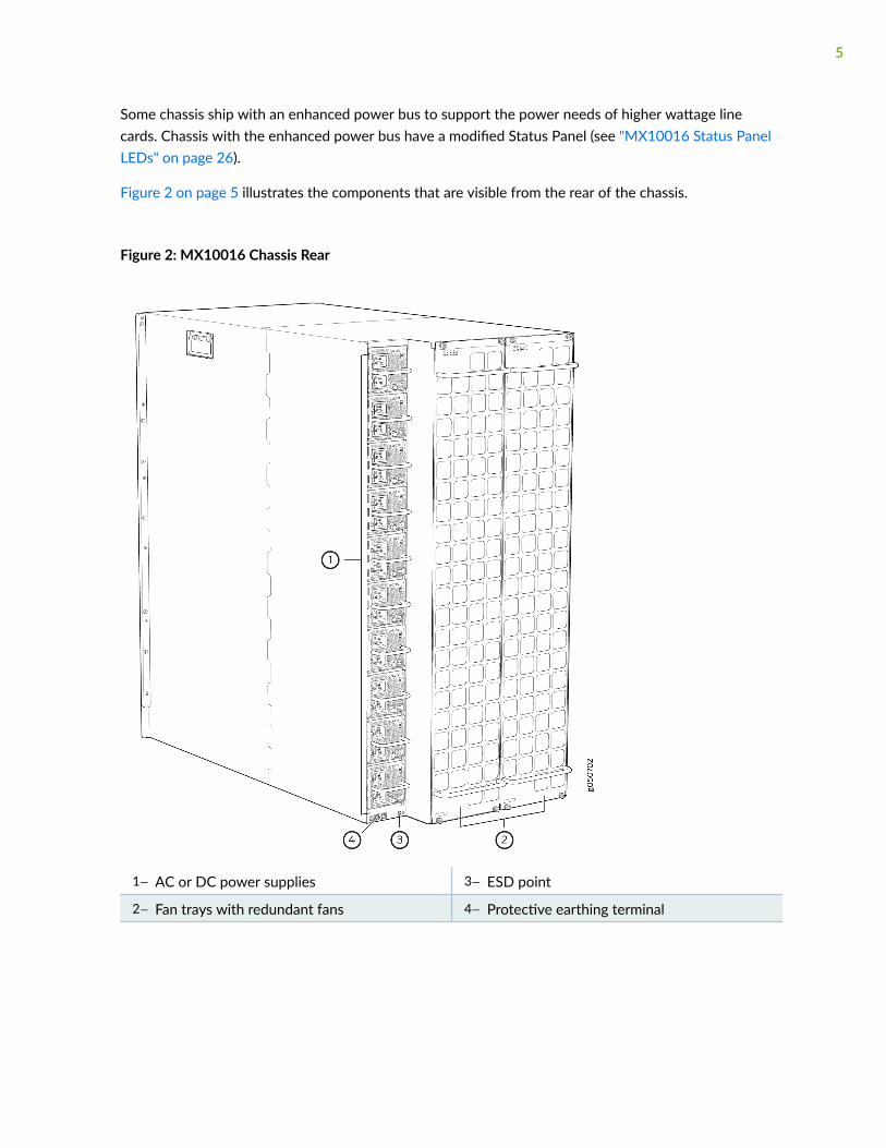
Some chassis ship with an enhanced power bus to support the power needs of higher wattage linecards. Chassis with the enhanced power bus have a modified Status Panel (see "MX10016 Status PanelLEDs" on page 26).
Figure 2 on page 5 illustrates the components that are visible from the rear of the chassis.
Figure 2: MX10016 Chassis Rear
1— AC or DC power supplies 3— ESD point
2— Fan trays with redundant fans 4— Protective earthing terminal
5
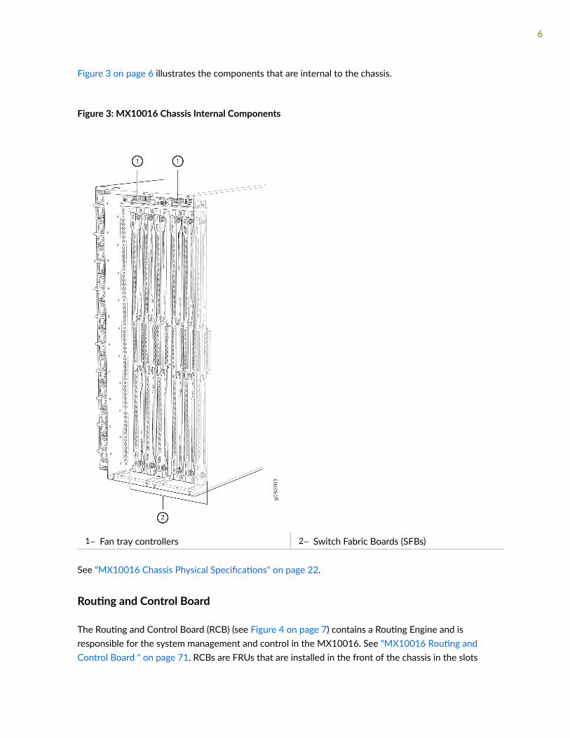
Figure 3 on page 6 illustrates the components that are internal to the chassis.
Figure 3: MX10016 Chassis Internal Components
1— Fan tray controllers 2— Switch Fabric Boards (SFBs)
See "MX10016 Chassis Physical Specifications" on page 22.
Routing and Control Board
The Routing and Control Board (RCB) (see Figure 4 on page 7) contains a Routing Engine and isresponsible for the system management and control in the MX10016. See "MX10016 Routing andControl Board " on page 71. RCBs are FRUs that are installed in the front of the chassis in the slots
6
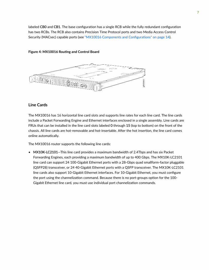
labeled CB0 and CB1. The base configuration has a single RCB while the fully redundant configurationhas two RCBs. The RCB also contains Precision Time Protocol ports and two Media Access ControlSecurity (MACsec) capable ports (see "MX10016 Components and Configurations" on page 14).
Figure 4: MX10016 Routing and Control Board
Line Cards
The MX10016 has 16 horizontal line card slots and supports line rates for each line card. The line cardsinclude a Packet Forwarding Engine and Ethernet interfaces enclosed in a single assembly. Line cards areFRUs that can be installed in the line card slots labeled 0 through 15 (top to bottom) on the front of thechassis. All line cards are hot-removable and hot-insertable. After the hot insertion, the line card comesonline automatically.
The MX10016 router supports the following line cards:
• MX10K-LC2101—This line card provides a maximum bandwidth of 2.4Tbps and has six PacketForwarding Engines, each providing a maximum bandwidth of up to 400 Gbps. The MX10K-LC2101line card can support 24 100-Gigabit Ethernet ports with a 28-Gbps quad smallform-factor pluggable(QSFP28) transceiver, or 24 40-Gigabit Ethernet ports with a QSFP transceiver. The MX10K-LC2101line cards also support 10-Gigabit Ethernet interfaces. For 10-Gigabit Ethernet, you must configurethe port using the channelization command. Because there is no port-groups option for the 100-Gigabit Ethernet line card, you must use individual port channelization commands.
7
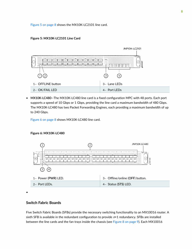
Figure 5 on page 8 shows the MX10K-LC2101 line card.
Figure 5: MX10K-LC2101 Line Card
1— OFFLINE button 3— Lane LEDs
2— OK/FAIL LED 4— Port LEDs
• MX10K-LC480—The MX10K-LC480 line card is a fixed configuration MPC with 48 ports. Each portsupports a speed of 10 Gbps or 1 Gbps, providing the line card a maximum bandwidth of 480 Gbps.The MX10K-LC480 has two Packet Forwarding Engines, each providing a maximum bandwidth of upto 240 Gbps.
Figure 6 on page 8 shows MX10K-LC480 line card.
Figure 6: MX10K-LC480
1— Power (PWR) LED. 3— Offline/online (OFF) button.
2— Port LEDs. 4— Status (STS) LED.
•
Switch Fabric Boards
Five Switch Fabric Boards (SFBs) provide the necessary switching functionality to an MX10016 router. Asixth SFB is available in the redundant configuration to provide n+1 redundancy. SFBs are installedbetween the line cards and the fan trays inside the chassis (see Figure 8 on page 9). Each MX10016
8

SFB has sixteen connectors that match to a line card slot, eliminating the need for a backplane. When allthe SFBs are installed, the MX10016 router has a net switching capacity of 2.4 terabytes per second(bidirectional). See "MX10016 Switch Fabric Board" on page 77.
Figure 8: MX10016 SFB
Cooling System
The cooling system in the MX10016 consists of two hot-removable and hot-insertable FRU fan traysand two fan tray controllers.
Two fan tray models (JNP10016-FAN and JNP10016-FAN2) and their associated fan tray controllers(JNP10016-FAN-CTRL and JNP10016-FTC2) are available. The fan trays install vertically on the rear of
9
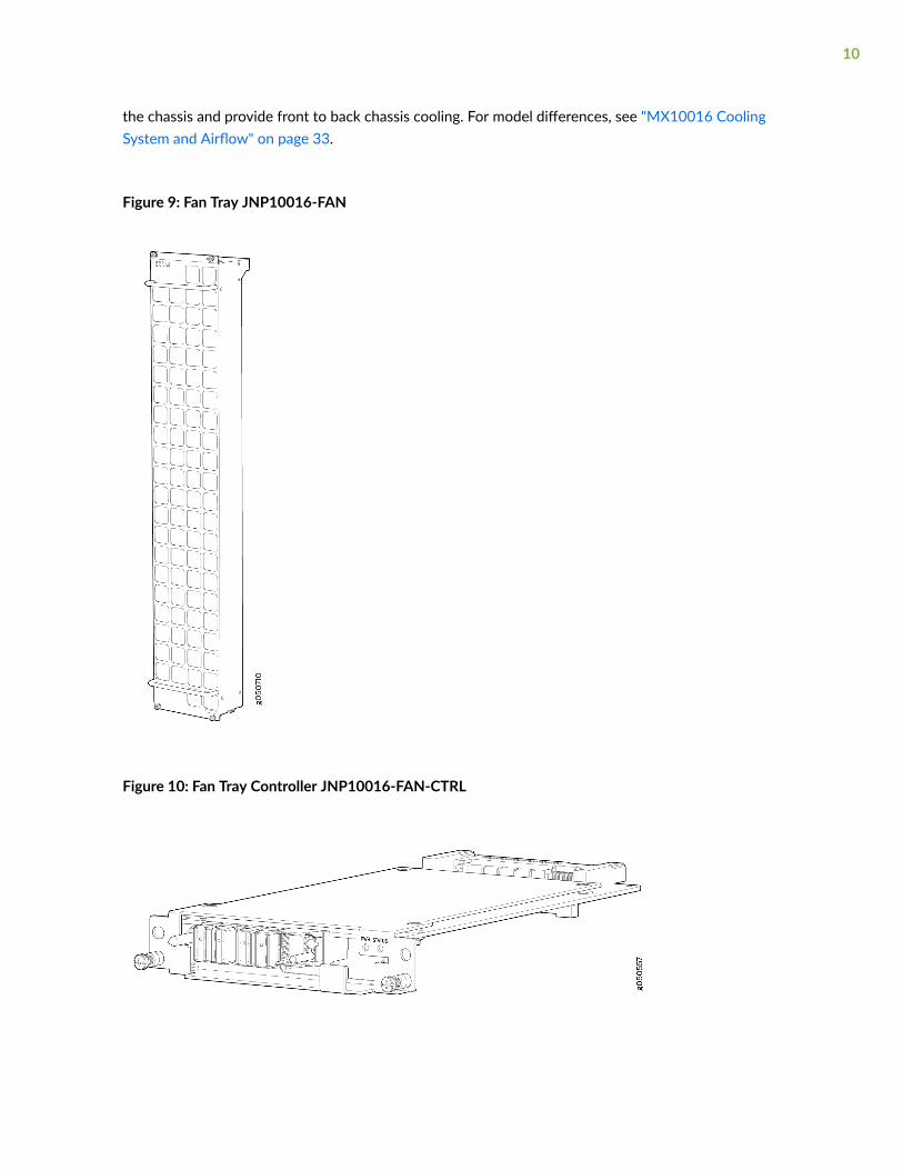
the chassis and provide front to back chassis cooling. For model differences, see "MX10016 CoolingSystem and Airflow" on page 33.
Figure 9: Fan Tray JNP10016-FAN
Figure 10: Fan Tray Controller JNP10016-FAN-CTRL
10

Power Supplies
Power supplies for the MX10016 router are fully redundant, load-sharing, and hot-removable and hot-insertable FRUs. Each MX10016 router with a base configuration has five power supplies; redundantconfigurations hold a maximum of ten AC or DC power supplies. Each power supply has an internal fanfor cooling. See Figure 11 on page 12 through Figure 14 on page 13.
11
CAUTION: Do not mix AC and DC power supplies in the same chassis.
Figure 11: JNP10K-PWR-AC Power Supply
Figure 12: JNP10K-PWR-AC2 Power Supply
12
Figure 13: JNP10K-PWR-DC Power Supply
Figure 14: JNP10K-PWR-DC2 Power Supply
Table 1 on page 13 provides an overview of the differences among the power supplies.
Table 1: Power Supply Overview
Power Supply Model Input Type Wattage Power Bus
JNP10K-PWR AC AC only 2700 W Standard or enhanced
JNP10K-PWR-AC2 AC, HVAC, or HVDC 5000 W, single feed; 5500 W, dual feed Enhanced
13

Table 1: Power Supply Overview (Continued)
Power Supply Model Input Type Wattage Power Bus
JNP10K-PWR DC DC only 2500 W Standard or enhanced
JNP10K-PWR-DC2 DC only 2750 W, single feed; 5500 W, dual feed Enhanced
Software on MX10016
The MX10016 router runs Junos OS, which provides Layer 3 routing services. The same Junos OS codebase that runs on the MX10016 router also runs on all Juniper Networks M Series, MX Series, andT Series routers and SRX Series Services Gateways.
MX10016 Components and Configurations
Table 2 on page 15 lists the four hardware configurations for an MX10016 modular chassis—base (ACversion), and redundant (AC and DC versions)—and the components included in each configuration.
14

Table 2: MX10016 Hardware Configurations
Router Configuration Configuration Components
Base AC configuration
MX10016-BASE
• Chassis
• One RCB (JNP10K-RE1, JNP10K-RE1-LT, or JNP10K-RE1-128)
• Two fan tray controllers (JNP10016-FAN-CTRL)
• Two fan trays (JNP10016-FAN)
• Five AC power supplies (JNP10K-PWR-AC)
• Five power supply slot covers
• Five switch fabric cards (JNP10016-SF)
• One switch fabric slot cover (JNP10016-SF-BLNK)
• Sixteen line-card covers
Base AC configuration with JNP10K-PWR-AC2 components
MX10016-BASE
• Chassis
• One RCB (JNP10K-RE1, JNP10K-RE1-LT, or JNP10K-RE1-128)
• Two fan tray controllers (JNP10016-FTC2)
• Two fan trays (JNP10016-FAN2)
• Five AC power supplies (JNP10K-PWR-AC2)
• Five power supply slot covers
• Five switch fabric cards (JNP10016-SF)
• One switch fabric slot cover (JNP10016-SF-BLNK)
• Sixteen line-card covers
15

Table 2: MX10016 Hardware Configurations (Continued)
Router Configuration Configuration Components
Base DC configuration
MX10016-BASE
• Chassis
• One RCB (JNP10K-RE1, JNP10K-RE1-LT, or JNP10K-RE1-128)
• Two fan tray controllers (JNP10016-FAN-CTRL)
• Two fan trays (JNP10016-FAN)
• Five DC power supplies (JNP10K-PWR-DC)
• Five power supply slot covers
• Five switch fabric cards (JNP10016-SF)
• One switch fabric slot cover (JNP10016-SF-BLNK)
• Sixteen line-card covers
Base DC configuration with JNP10K-PWR-DC2 components
MX10016-BASE
• Chassis
• One RCB (JNP10K-RE1, JNP10K-RE1-LT, or JNP10K-RE1-128)
• Two fan tray controllers (JNP10016-FTC2)
• Two fan trays (JNP10016-FAN2)
• Five DC power supplies (JNP10K-PWR-DC2)
• Five power supply slot covers
• Five switch fabric cards (JNP10016-SF)
• One switch fabric slot cover (JNP10016-SF-BLNK)
• Sixteen line-card covers
16

Table 2: MX10016 Hardware Configurations (Continued)
Router Configuration Configuration Components
Redundant AC configuration
MX10016-PREMIUM
• Chassis
• Two RCBs (JNP10K-RE1, JNP10K-RE1-LT, or JNP10K-RE1-128)
• Two fan tray controllers (JNP10016-FAN-CTRL)
• Two fan trays (JNP10016-FAN)
• Ten AC power supplies (JNP10K-PWR-AC)
• Six switch fabric cards (JNP10016-SF)
• Sixteen line-card covers
Redundant AC configuration withJNP10K-PWR-AC2 components
MX10016-PREMIUM
• Chassis
• Two RCBs (JNP10K-RE1, JNP10K-RE1-LT, or JNP10K-RE1-128)
• Two fan tray controllers (JNP10016-FTC2)
• Two fan trays (JNP10016-FAN2)
• Ten AC power supplies (JNP10K-PWR-AC2)
• Six switch fabric cards (JNP10016-SF2)
• Sixteen line-card covers
Redundant DC configuration
MX10016-PREMIUM
• Chassis
• Two RCBs (JNP10K-RE1, JNP10K-RE1-LT, or JNP10K-RE1-128)
• Two fan tray controllers (JNP10016-FAN-CTRL)
• Two fan trays (JNP10016-FAN)
• Ten DC power supplies (JNP10K-PWR-DC)
• Six switch fabric cards (JNP10016-SF)
• Sixteen line-card covers
17

Table 2: MX10016 Hardware Configurations (Continued)
Router Configuration Configuration Components
Redundant DC configuration withJNP10K-PWR-DC2 components
MX10016-PREMIUM
• Chassis
• Two RCBs (JNP10K-RE1, JNP10K-RE1-LT, or JNP10K-RE1-128)
• Two fan tray controllers (JNP10016-FTC2)
• Two fan trays (JNP10016-FAN2)
• Ten DC power supplies (JNP10K-PWR-DC2)
• Six switch fabric cards (JNP10016-SF2)
• Sixteen line-card covers
NOTE: You can install up to sixteen line cards in the router.
NOTE: Line cards and the cable management system are not part of the base or redundantconfigurations. You must order them separately.
NOTE: If you want to purchase additional power supplies (AC or DC), SFBs, or RCBs for yourrouter configuration, you must order them separately.
MX10016 Component Redundancy
The MX10016 router is designed so that no single point of failure can cause the entire system to fail.The following major hardware components in the redundant configuration provide redundancy:
• Routing and Control Board (RCB)—The RCB consolidates the Routing Engine function with thecontrol plane function in a single unit. The MX10016 router can have one RCB in a baseconfiguration or two RCBs in a redundant configuration. When two RCBs are installed, one functionsas the primary and the other functions as the backup. If the primary RCB (or either of its
18

components) fails, the backup can take over as the primary RCB. See "MX10016 Routing and ControlBoard " on page 71.
• Switch Fabric Boards (SFBs)—The MX10016 router has six SFB slots. Five SFBs are required for baseoperation and the sixth SFB provides n+1 redundancy. All six SFBs are active and can sustain fullthroughput rate. The fabric plane can tolerate one SFB failure without any loss of performance. See"MX10016 Switch Fabric Board" on page 77.
• Power supplies—The MX10016 router requires three power supplies for minimum operation.Additional power supplies, provide n+1 redundancy for the system. AC, DC, HVAC, and HVDCsystems tolerate a single power supply to fail without system interruption. If one power supply failsin a fully redundant system, the other power supplies can provide full power to the MX10016 routerindefinitely.
The MX10016 router also supports source redundancy. Two sets of lugs are provided for theJNP10K-PWR-AC cables, four sets of lugs are provided for the JNP10K-PWR-DC2 cables, and twoAC power cords are provided for each JNP10K-PWR-AC2 power supply.
• Cooling system—The fan trays have redundant fans, which are controlled by the fan tray controller. Ifone of the fans fails, the host subsystem increases the speed of the remaining fans to providesufficient cooling for the router indefinitely. See "MX10016 Cooling System " on page 33.
MX10016 Hardware and CLI Terminology Mapping
This topic describes the hardware terms used in MX10016 router documentation and the correspondingterms used in the Junos OS CLI. See Table 3 on page 19.
Table 3: CLI Equivalents of Terms Used in Documentation for MX10016 Routers
HardwareItem (CLI)
Description (CLI) Value (CLI) Item inDocumentation
Additional Information
Chassis JNP10016[MX10016]
– Router chassis "MX10016 ChassisPhysical Specifications"on page 22
19

Table 3: CLI Equivalents of Terms Used in Documentation for MX10016 Routers (Continued)
HardwareItem (CLI)
Description (CLI) Value (CLI) Item inDocumentation
Additional Information
Routing andControlBoard
CB (n) n is a value in the rangeof 0–1.
Multiple line itemsappear in the CLI ifmore than one RCB isinstalled in the chassis.
"MX10016 Routing andControl Board " onpage 71
FPC (n) Abbreviatedname of theFlexible PICConcentrator(FPC)
On MX10016, anFPC equates to aline card.
n is a value in the rangeof 0–15. The valuecorresponds to the linecard slot number inwhich the line card isinstalled.
Line card (The routerdoes not have actualFPCs—the line cardsare the FPCequivalents on therouter.)
UnderstandingInterface NamingConventions
Xcvr (n) Abbreviatedname of thetransceiver
n is a value equivalentto the number of theport in which thetransceiver is installed.
Optical transceivers "MX10016 Transceiverand CableSpecifications" on page122
PSU (n) One of thefollowing:
• JNP10K-PWR-AC
• JNP10K-PWR-AC2
• JNP10K-PWR-DC
• JNP10K-PWR-DC2
n is a value in the rangeof 0–9. The valuecorresponds to thepower supply slotnumber.
AC or DC powersupply
One of the following:
• "JNP10K-PWR-ACPower Supply" onpage 51
•
• "JNP10K-PWR-DCPower Supply" onpage 56
•
20
Table 3: CLI Equivalents of Terms Used in Documentation for MX10016 Routers (Continued)
HardwareItem (CLI)
Description (CLI) Value (CLI) Item inDocumentation
Additional Information
Fan tray JNP10016-FANor JNP10016-FAN2
– Fan tray "MX10016 CoolingSystem " on page 33
SFB (n) This fieldindicates:
• State of thefabric plane:
• Active
• Spare
• CheckState
• Status of thePacketForwardingEngine ineach fabricplane:
• Links OK
• Error
n is a value in the rangeof 0–5.
Fabric plane show chassis sfb
MX10016 Chassis
IN THIS SECTION
MX10016 Chassis Physical Specifications | 22
MX10016 Field-Replaceable Units | 25
21
MX10016 Status Panel LEDs | 26
MX10016 Optional Equipment | 30
MX10016 Chassis Physical Specifications
The MX10016 modular chassis is a rigid sheet-metal structure that houses the field-replaceable units(FRUs). You can mount up to two MX10016 chassis in a standard 19-in. four-post (42 U) rack, providedthe rack can handle the combined weight and there is adequate power and cooling.Table 4 on page 22summarizes the physical specifications of the chassis. See Figure 15 on page 24.
Table 4: MX10016 Chassis Physical Specifications
Description Weight Height Width Depth
Chassis, spare 220 lb (99.79kg)
36.6 in.(92.96 cm)
17.4 in. (44.2 cm)
NOTE: The outer edges ofthe mounting-bracketflange extend the width to19 in. (48.3 cm).
35 in.(88.9 cm)
Chassis base AC configuration
Includes 1 Control Board, 5AC power supplies, 2 fantrays, 2 fan tray controllers,and 5 Switch Ffabric Boards(SFBs)
522 lb(236.78 kg)
36.6 in.(92.96 cm)
17.4 in. (44.2 cm)
NOTE: The outer edges ofthe mounting-bracketflange extend the width to19 in. (48.3 cm).
35 in.(88.9 cm)
Chassis redundant ACconfiguration
Includes 2 Control Boards, 10AC power supplies, 2 fantrays, 2 fan tray controllers,and 6 SIBs
596 lb(270.34 kg)
36.6 in.(92.96 cm)
17.4 in. (44.2 cm)
NOTE: The outer edges ofthe mounting-bracketflange extend the width to19 in. (48.3 cm).
35 in.(88.9 cm)
22

Table 4: MX10016 Chassis Physical Specifications (Continued)
Description Weight Height Width Depth
Chassis base DC configuration
Includes 1 Control Board, 5DC power supplies, 2 fantrays, 2 fan tray controllers,and 5 SIBs
519.5 lb(235.65 kg)
36.6 in.(92.96 cm)
17.4 in. (44.2 cm)
NOTE: The outer edges ofthe mounting-bracketflange extend the width to19 in. (48.3 cm).
35 in.(88.9 cm)
Chassis redundant DCconfiguration
Includes 2 Control Boards, 10DC power supplies, 2 fantrays, 2 fan tray controllers,and 6 SIBs
591 lb(268.07 kg)
36.6 in.(92.96 cm)
17.4 in. (44.2 cm)
NOTE: The outer edges ofthe mounting-bracketflange extend the width to19 in. (48.3 cm).
35 in.(88.9 cm)
MX10K-LC2101 Line Card 31.57 lb (14.32kg)
1.89 in. (48.01mm)
17.2 in (436.88 mm) 19.05 in. (484mm)(ExcludingFRU Ejector)
MX10K-LC480 Line Card 21.6 lb (9.8 kg) 1.89 in. (48.01mm)
17.2 in (436.88 mm) 19.05 in. (484mm)(ExcludingFRU Ejector)
23

Figure 15: Front View of an MX10016
1— Routing and Control Boards 4— Mounting holes for front panel
2— Status panel 5— Line cards
3— Handles
WARNING: The handles on each side of the chassis facilitate the fine-tune positioningof the chassis on the mounting brackets. Do not use the handles to lift the chassis, evenwhen the chassis is empty. See "Installing an MX10016 into a Four-Post Rack" on page146 for instructions for properly moving a loaded chassis.
24

MX10016 Field-Replaceable Units
Field-replaceable units (FRUs) are router components that you can replace at your site. The router usesthese types of FRUs:
• Hot-insertable and hot-removable—You can remove and replace these components without poweringoff the router or disrupting the routing function.
• Hot-pluggable—You can remove and replace these components without powering off the router, butthe routing function is interrupted until you replace the component.
Table 5 on page 25 lists the FRUs and their types for the MX10016 routers.
Table 5: Field-Replaceable Units in an MX10016 Router
FRU Type
Power supplies Hot-insertable and hot-removable.
Fan tray Hot-insertable and hot-removable.
Fan tray controller Hot-insertable and hot-removable.
Routing and Control Board(RCB)
Redundant configuration:
• Primary RCB is hot-pluggable.
• Backup RCB is hot-insertable and hot-removable.
Base configuration:
• Removing the RCB causes the router to shut down. You can install areplacement Control Board in the second slot. The system restarts to electa primary and backup. If necessary, you can switch the primary and backupusing the request chassis routing-engine master switch command. Werecommend that you take the backup RCB offline before removing it.
See "MX10016 Components and Configurations" on page 14.
25

Table 5: Field-Replaceable Units in an MX10016 Router (Continued)
FRU Type
Switch Fabric Boards (SFBs) SFBs are hot-insertable and hot-removable. We recommend that you takeSFBs offline before removing them to avoid traffic loss while the router fabricis being reconfigured. Use the following command:
user@router> request chassis sib (offline | online) slot slot-number offline
Line cards Hot-insertable and hot-removable. We recommend that you take line cardsoffline before removing them. For example:
user@router> request chassis fpc slot slot-number offline
Optical transceivers Hot-insertable and hot-removable.
NOTE: Line cards are not part of the base or redundant configuration. You must order themseparately.
NOTE: If you have a Juniper Care service contract, register any addition, change, or upgrade ofhardware components at https://www.juniper.net/customers/support/tools/updateinstallbase/.Failure to do so can result in significant delays if you need replacement parts. This note does notapply if you replace an existing component with the same type of component.
SEE ALSO
MX10016 Components and Configurations | 14
MX10016 Status Panel LEDs
The status panel of the MX10016 routers has two purposes:
26
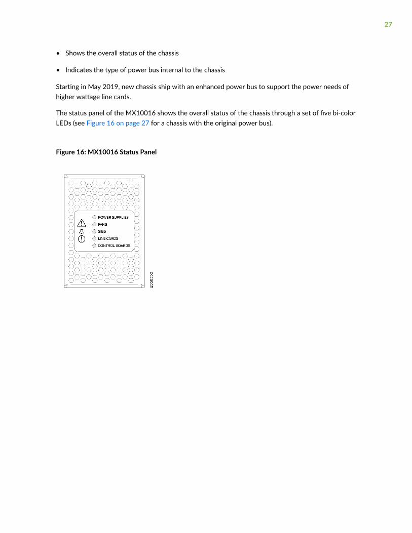
• Shows the overall status of the chassis
• Indicates the type of power bus internal to the chassis
Starting in May 2019, new chassis ship with an enhanced power bus to support the power needs ofhigher wattage line cards.
The status panel of the MX10016 shows the overall status of the chassis through a set of five bi-colorLEDs (see Figure 16 on page 27 for a chassis with the original power bus).
Figure 16: MX10016 Status Panel
27

Chassis that are shipped after May 2019 have the same set of five bi-color LEDs, but also have an azureblue line to indicate the enhanced power bus (see Figure 17 on page 28).
Figure 17: Status Panel on Chassis with the Enhanced Power Bus
Table 6 on page 28 describes the status panel LEDs.
Table 6: Status Panel LEDs in an MX10016 Router
Name Color State Description
Power supplies Green On steadily All of the power supplies are online andoperating normally.
Yellow On steadily One or more of the power supplies havean error.
None Off None of the power supplies is receivingpower.
Fans Green On steadily The fans and the fan tray controllers areonline and operating normally.
Yellow On steadily There is an error in a fan or in one of thefan tray controllers.
28
Table 6: Status Panel LEDs in an MX10016 Router (Continued)
Name Color State Description
None Off The fan tray controllers and fan trays arenot receiving power.
SFBs Green On steadily All installed Switch Fabric Boards (SFBs)are online.
Yellow Blinking There is a hardware error in one or moreSFBs.
None Off All the SFBs are offline.
Line cards Green On steadily All the line cards are online.
Yellow Blinking There is a hardware error in one or moreline cards.
None Off All the line cards are offline.
Routing and ControlBoards
Green On steadily All the RCBs are online.
Yellow Blinking One or more Routing and ControlBoards have an error condition.
None Off All the installed Routing and ControlBoards are offline.
29

Table 6: Status Panel LEDs in an MX10016 Router (Continued)
Name Color State Description
Alarms Red On steadily Major (red)—Indicates a critical situationon the device that has resulted from oneof the following conditions.
• One or more hardware componentshave failed.
• One or more hardware componentshave exceeded temperaturethresholds.
• An alarm condition configured on aninterface has triggered a criticalwarning.
A red alarm condition requiresimmediate action.
Yellow On steadily Minor (yellow or amber)—Indicates anoncritical condition on the device that,if left unnoticed, might cause aninterruption in service or degradation inperformance.
A yellow alarm condition requiresmonitoring or maintenance. Forexample, a missing rescue configurationgenerates a yellow system alarm.
MX10016 Optional Equipment
The MX10016 router supports the cable management system as an optional piece of equipment.
30

The cable management system (see Figure 18 on page 31) enables you to route optical cables awayfrom the line card ports for better airflow through the chassis. Using this optional system also makes iteasier to use cable ties or strips to organize the cabling.
Figure 18: MX10016 Cable Management System
The cable management system is comprises a set of handle extensions and a tray that snaps to theextensions (see Figure 19 on page 31) for an individual line card. The handle extensions can be usedwith or without the cable tray. It is not necessary to remove the handle extensions if you want toremove a line card.
Figure 19: MX10016 Cable Management Parts
1— Handle extensions 2— Cable tray
31
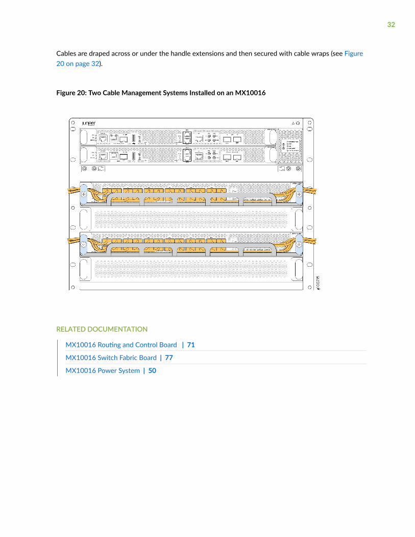
Cables are draped across or under the handle extensions and then secured with cable wraps (see Figure20 on page 32).
Figure 20: Two Cable Management Systems Installed on an MX10016
RELATED DOCUMENTATION
MX10016 Routing and Control Board | 71
MX10016 Switch Fabric Board | 77
MX10016 Power System | 50
32

MX10016 Cooling System
IN THIS SECTION
MX10016 Cooling System and Airflow | 33
MX10016 Fan Tray LEDs and Fan Tray Controller LEDs | 43
The MX10016 cooling system components work together to keep all components within the acceptabletemperature range. If the maximum temperature specification is exceeded and the system cannot beadequately cooled, the Routing and Control Board shuts down some or all of the hardware components.For more information, see the following topics:
MX10016 Cooling System and Airflow
IN THIS SECTION
MX10016 Fan Trays | 34
MX10016 Fan Tray Controllers | 37
Airflow Direction in an MX10016 | 42
The cooling system in an MX10016 chassis consists of two fan trays and two fan tray controllers. AnMX10016 has an air filter on the front panel. Two fan tray models (JNP10016-FAN and JNP10016-FAN2) and their associated fan tray controllers (JNP10016-FAN-CTRL and JNP10016-FTC2) areavailable. The JNP10016-FAN fans in each JNP10016-FAN-CTRL fan tray are numbered 0 through 20.The JNP10016-FAN2 fans in each JNP10016-FTC2 fan tray are numbered 0 through 41.
All models are hot-insertable and hot-removable. See "MX10016 Cooling System and Airflow" on page33.
33

Table 7: Fan Tray Specifications
Specification JNP10016-FAN JNP10016-FAN2
Corresponding fan tray controllermodel
JNP10016-FAN-CTLR JNP10016-FTC2
Number of fans per fan tray 21 42
Number of fans per chassis 42 84
Volume flow at 100% 130.67 CFM per fan or 2,744.07CFM per fan tray
163 CFM per fan or 3,423 CFMper fan tray
Introduced in Junos OS Release 15.1X53-D30 19.2R1-S1
Height 36.6 in. (92.97 cm) 36.5 in. (92.97 cm)
Width 6.6 in. (16.8 cm) 6.6 in. (16.8 cm)
Depth 4.0 in. (10.2 cm) without handles,5.2 in. (13.2 cm) with handles
5.5 in. (13.97 cm) without handles,6.7 in. (17.01 cm)
Weight 19.8 lb (8.98 kg) 33.8 lb (15.33 kg)
The JNP10016-FAN2 and JNP10016-FAN2-CTRL are optimized to work best in the enhanced chassis,but are backwards compatible to work in the standard chassis. To determine which chassis you have, see"MX10016 Status Panel LEDs" on page 26.
MX10016 Fan Trays
Each fan tray is a hot-insertable and hot-removable FRU. Each fan tray has a non-removable ControlBoard, and LEDs.
34

The two fan trays install vertically, side by side, next to the power supplies on the rear side of thechassis. Two handles on each front faceplate facilitate handling of the fan tray. See Figure 21 on page35 and Figure 22 on page 36 .
Figure 21: Fan Tray JNP10016-FAN
35
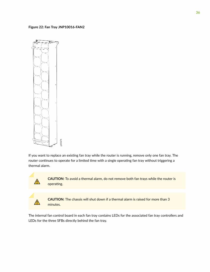
Figure 22: Fan Tray JNP10016-FAN2
If you want to replace an existing fan tray while the router is running, remove only one fan tray. Therouter continues to operate for a limited time with a single operating fan tray without triggering athermal alarm.
CAUTION: To avoid a thermal alarm, do not remove both fan trays while the router isoperating.
CAUTION: The chassis will shut down if a thermal alarm is raised for more than 3minutes.
The internal fan control board in each fan tray contains LEDs for the associated fan tray controllers andLEDs for the three SFBs directly behind the fan tray.
36

MX10016 Fan Tray Controllers
Two fan tray controllers provide the control logic and power to hot-insert and hot-remove a fan tray.The fans in each fan tray are numbered 0 through 20.
The system continually monitors the temperature of critical parts across the chassis and adjusts thechassis fan speed according to the temperature.
There are two fan tray controller models:
• JNP10016-FAN-CTRL—Supports the model JNP10016-FAN. See Figure 23 on page 37.
Figure 23: Fan Tray Controller JNP10016-FAN-CTRL
• JNP10016-FTC2—Supports the model JNP10016-FAN2. See Figure 24 on page 37.
Figure 24: Fan Controller JNP10016-FTC2
Software controls the fan speed. Under normal operating conditions, the fans in the fan tray run at lessthan full speed.If one fan tray controller fails or appears missing (such as when an SFB is being replaced),the other fan tray controller sets the fans to full speed. This enables the router to continue to operate
37

normally as long as the remaining fans cool the chassis sufficiently. Use the show chassis fan command tosee the status of individual fans and the fan speed.
Output for JNP10016-FAN and JNP10016-FAN-CTRL
user@device> show chassis fan
Item Status RPM Measurement Fan Tray 0 Fan 0 OK 7950 Spinning at normal speed Fan Tray 0 Fan 1 OK 7800 Spinning at normal speed Fan Tray 0 Fan 2 OK 7800 Spinning at normal speed Fan Tray 0 Fan 3 OK 7950 Spinning at normal speed Fan Tray 0 Fan 4 OK 7650 Spinning at normal speed Fan Tray 0 Fan 5 OK 7650 Spinning at normal speed Fan Tray 0 Fan 6 OK 7650 Spinning at normal speed Fan Tray 0 Fan 7 OK 7650 Spinning at normal speed Fan Tray 0 Fan 8 OK 7650 Spinning at normal speed Fan Tray 0 Fan 9 OK 7650 Spinning at normal speed Fan Tray 0 Fan 10 OK 7650 Spinning at normal speed Fan Tray 0 Fan 11 OK 7650 Spinning at normal speed Fan Tray 0 Fan 12 OK 7800 Spinning at normal speed Fan Tray 0 Fan 13 OK 7650 Spinning at normal speed Fan Tray 0 Fan 14 OK 7650 Spinning at normal speed Fan Tray 0 Fan 15 OK 7650 Spinning at normal speed Fan Tray 0 Fan 16 OK 7650 Spinning at normal speed Fan Tray 0 Fan 17 OK 7650 Spinning at normal speed Fan Tray 0 Fan 18 OK 7800 Spinning at normal speed Fan Tray 0 Fan 19 OK 7650 Spinning at normal speed Fan Tray 0 Fan 20 OK 7650 Spinning at normal speed Fan Tray 1 Fan 0 OK 7650 Spinning at normal speed Fan Tray 1 Fan 1 OK 7650 Spinning at normal speed Fan Tray 1 Fan 2 OK 7650 Spinning at normal speed Fan Tray 1 Fan 3 OK 7650 Spinning at normal speed Fan Tray 1 Fan 4 OK 7800 Spinning at normal speed Fan Tray 1 Fan 5 OK 7650 Spinning at normal speed Fan Tray 1 Fan 6 OK 7800 Spinning at normal speed Fan Tray 1 Fan 7 OK 7650 Spinning at normal speed Fan Tray 1 Fan 8 OK 7800 Spinning at normal speed Fan Tray 1 Fan 9 OK 7650 Spinning at normal speed Fan Tray 1 Fan 10 OK 7650 Spinning at normal speed Fan Tray 1 Fan 11 OK 7500 Spinning at normal speed
38

Fan Tray 1 Fan 12 OK 7650 Spinning at normal speed Fan Tray 1 Fan 13 OK 7650 Spinning at normal speed Fan Tray 1 Fan 14 OK 7650 Spinning at normal speed Fan Tray 1 Fan 15 OK 7500 Spinning at normal speed Fan Tray 1 Fan 16 OK 7650 Spinning at normal speed Fan Tray 1 Fan 17 OK 7500 Spinning at normal speed Fan Tray 1 Fan 18 OK 7500 Spinning at normal speed Fan Tray 1 Fan 19 OK 7500 Spinning at normal speed Fan Tray 1 Fan 20 OK 7500 Spinning at normal speed
Output for JNP10016-FAN2 and JNP10016-FTC2
user@router> show chassis fan Item Status RPM Measurement Fan Tray 0 Fan 0 OK 3900 Spinning at normal speed Fan Tray 0 Fan 1 OK 5250 Spinning at normal speed Fan Tray 0 Fan 2 OK 3750 Spinning at normal speed Fan Tray 0 Fan 3 OK 5100 Spinning at normal speed Fan Tray 0 Fan 4 OK 3900 Spinning at normal speed Fan Tray 0 Fan 5 OK 5250 Spinning at normal speed Fan Tray 0 Fan 6 OK 3750 Spinning at normal speed Fan Tray 0 Fan 7 OK 5100 Spinning at normal speed Fan Tray 0 Fan 8 OK 3750 Spinning at normal speed Fan Tray 0 Fan 9 OK 5250 Spinning at normal speed Fan Tray 0 Fan 10 OK 3750 Spinning at normal speed Fan Tray 0 Fan 11 OK 5100 Spinning at normal speed Fan Tray 0 Fan 12 OK 3750 Spinning at normal speed Fan Tray 0 Fan 13 OK 5100 Spinning at normal speed Fan Tray 0 Fan 14 OK 3600 Spinning at normal speed Fan Tray 0 Fan 15 OK 5250 Spinning at normal speed Fan Tray 0 Fan 16 OK 3750 Spinning at normal speed Fan Tray 0 Fan 17 OK 5100 Spinning at normal speed Fan Tray 0 Fan 18 OK 3750 Spinning at normal speed Fan Tray 0 Fan 19 OK 5100 Spinning at normal speed Fan Tray 0 Fan 20 OK 3750 Spinning at normal speed Fan Tray 0 Fan 21 OK 4950 Spinning at normal speed Fan Tray 0 Fan 22 OK 3750 Spinning at normal speed Fan Tray 0 Fan 23 OK 5100 Spinning at normal speed Fan Tray 0 Fan 24 OK 3900 Spinning at normal speed Fan Tray 0 Fan 25 OK 5100 Spinning at normal speed Fan Tray 0 Fan 26 OK 3750 Spinning at normal speed Fan Tray 0 Fan 27 OK 5100 Spinning at normal speed
39
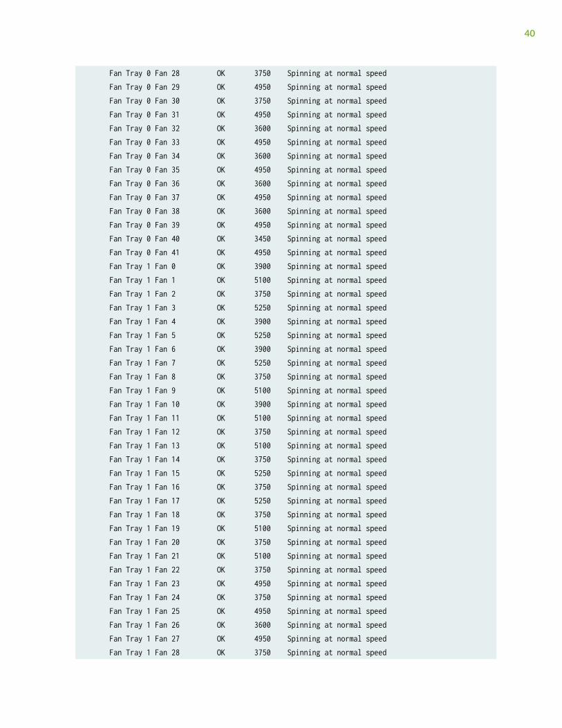
Fan Tray 0 Fan 28 OK 3750 Spinning at normal speed Fan Tray 0 Fan 29 OK 4950 Spinning at normal speed Fan Tray 0 Fan 30 OK 3750 Spinning at normal speed Fan Tray 0 Fan 31 OK 4950 Spinning at normal speed Fan Tray 0 Fan 32 OK 3600 Spinning at normal speed Fan Tray 0 Fan 33 OK 4950 Spinning at normal speed Fan Tray 0 Fan 34 OK 3600 Spinning at normal speed Fan Tray 0 Fan 35 OK 4950 Spinning at normal speed Fan Tray 0 Fan 36 OK 3600 Spinning at normal speed Fan Tray 0 Fan 37 OK 4950 Spinning at normal speed Fan Tray 0 Fan 38 OK 3600 Spinning at normal speed Fan Tray 0 Fan 39 OK 4950 Spinning at normal speed Fan Tray 0 Fan 40 OK 3450 Spinning at normal speed Fan Tray 0 Fan 41 OK 4950 Spinning at normal speed Fan Tray 1 Fan 0 OK 3900 Spinning at normal speed Fan Tray 1 Fan 1 OK 5100 Spinning at normal speed Fan Tray 1 Fan 2 OK 3750 Spinning at normal speed Fan Tray 1 Fan 3 OK 5250 Spinning at normal speed Fan Tray 1 Fan 4 OK 3900 Spinning at normal speed Fan Tray 1 Fan 5 OK 5250 Spinning at normal speed Fan Tray 1 Fan 6 OK 3900 Spinning at normal speed Fan Tray 1 Fan 7 OK 5250 Spinning at normal speed Fan Tray 1 Fan 8 OK 3750 Spinning at normal speed Fan Tray 1 Fan 9 OK 5100 Spinning at normal speed Fan Tray 1 Fan 10 OK 3900 Spinning at normal speed Fan Tray 1 Fan 11 OK 5100 Spinning at normal speed Fan Tray 1 Fan 12 OK 3750 Spinning at normal speed Fan Tray 1 Fan 13 OK 5100 Spinning at normal speed Fan Tray 1 Fan 14 OK 3750 Spinning at normal speed Fan Tray 1 Fan 15 OK 5250 Spinning at normal speed Fan Tray 1 Fan 16 OK 3750 Spinning at normal speed Fan Tray 1 Fan 17 OK 5250 Spinning at normal speed Fan Tray 1 Fan 18 OK 3750 Spinning at normal speed Fan Tray 1 Fan 19 OK 5100 Spinning at normal speed Fan Tray 1 Fan 20 OK 3750 Spinning at normal speed Fan Tray 1 Fan 21 OK 5100 Spinning at normal speed Fan Tray 1 Fan 22 OK 3750 Spinning at normal speed Fan Tray 1 Fan 23 OK 4950 Spinning at normal speed Fan Tray 1 Fan 24 OK 3750 Spinning at normal speed Fan Tray 1 Fan 25 OK 4950 Spinning at normal speed Fan Tray 1 Fan 26 OK 3600 Spinning at normal speed Fan Tray 1 Fan 27 OK 4950 Spinning at normal speed Fan Tray 1 Fan 28 OK 3750 Spinning at normal speed
40
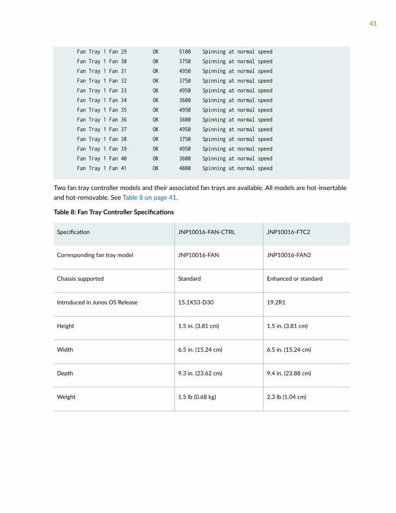
Fan Tray 1 Fan 29 OK 5100 Spinning at normal speed Fan Tray 1 Fan 30 OK 3750 Spinning at normal speed Fan Tray 1 Fan 31 OK 4950 Spinning at normal speed Fan Tray 1 Fan 32 OK 3750 Spinning at normal speed Fan Tray 1 Fan 33 OK 4950 Spinning at normal speed Fan Tray 1 Fan 34 OK 3600 Spinning at normal speed Fan Tray 1 Fan 35 OK 4950 Spinning at normal speed Fan Tray 1 Fan 36 OK 3600 Spinning at normal speed Fan Tray 1 Fan 37 OK 4950 Spinning at normal speed Fan Tray 1 Fan 38 OK 3750 Spinning at normal speed Fan Tray 1 Fan 39 OK 4950 Spinning at normal speed Fan Tray 1 Fan 40 OK 3600 Spinning at normal speed Fan Tray 1 Fan 41 OK 4800 Spinning at normal speed
Two fan tray controller models and their associated fan trays are available. All models are hot-insertableand hot-removable. See Table 8 on page 41.
Table 8: Fan Tray Controller Specifications
Specification JNP10016-FAN-CTRL JNP10016-FTC2
Corresponding fan tray model JNP10016-FAN JNP10016-FAN2
Chassis supported Standard Enhanced or standard
Introduced in Junos OS Release 15.1X53-D30 19.2R1
Height 1.5 in. (3.81 cm) 1.5 in. (3.81 cm)
Width 6.5 in. (15.24 cm) 6.5 in. (15.24 cm)
Depth 9.3 in. (23.62 cm) 9.4 in. (23.88 cm)
Weight 1.5 lb (0.68 kg) 2.3 lb (1.04 cm)
41
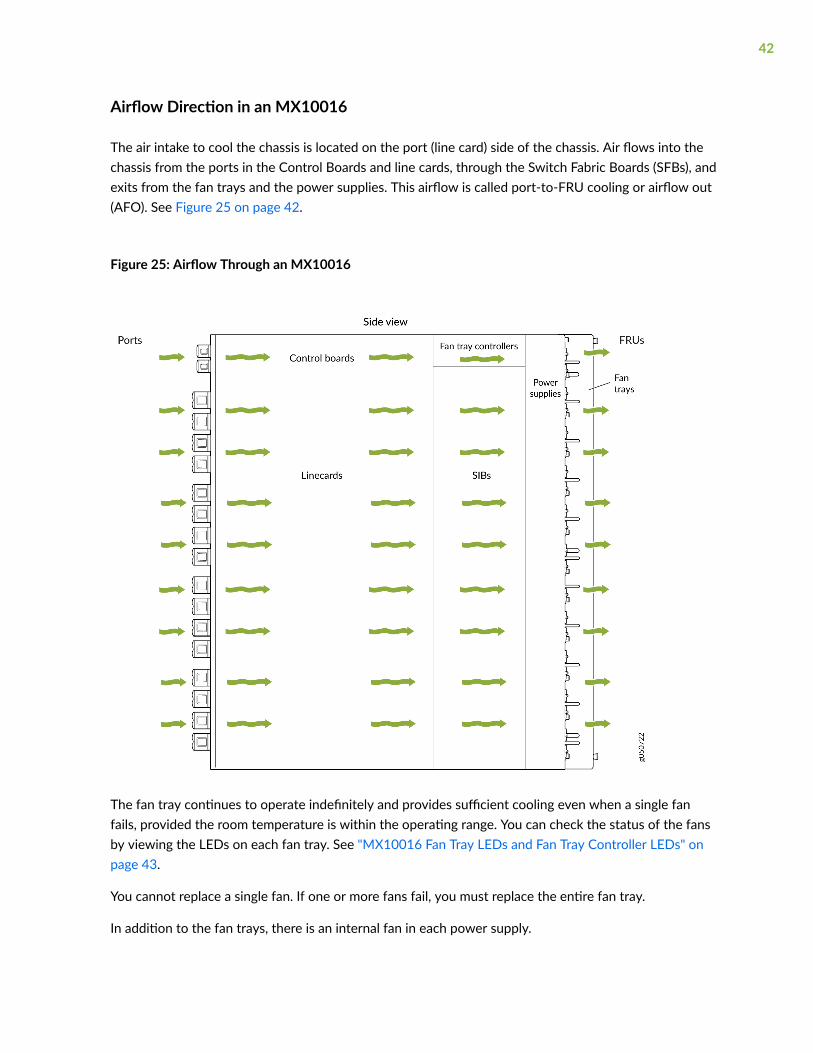
Airflow Direction in an MX10016
The air intake to cool the chassis is located on the port (line card) side of the chassis. Air flows into thechassis from the ports in the Control Boards and line cards, through the Switch Fabric Boards (SFBs), andexits from the fan trays and the power supplies. This airflow is called port-to-FRU cooling or airflow out(AFO). See Figure 25 on page 42.
Figure 25: Airflow Through an MX10016
The fan tray continues to operate indefinitely and provides sufficient cooling even when a single fanfails, provided the room temperature is within the operating range. You can check the status of the fansby viewing the LEDs on each fan tray. See "MX10016 Fan Tray LEDs and Fan Tray Controller LEDs" onpage 43.
You cannot replace a single fan. If one or more fans fail, you must replace the entire fan tray.
In addition to the fan trays, there is an internal fan in each power supply.
42

MX10016 Fan Tray LEDs and Fan Tray Controller LEDs
IN THIS SECTION
MX10016 Fan Tray LEDs | 43
MX10016 Fan Tray Controller LEDs | 48
Each fan tray has a set of LEDs, and each corresponding fan tray controller also has a set of LEDs. Thistopic covers:
MX10016 Fan Tray LEDs
Each of the two fan trays have a set of LEDs that represent the status of the fans in the fan tray, the fantray controller, and the three Switch Fabric Boards (SFBs). The fan tray LEDs are located in the top-leftcorner of each fan tray. Figure 26 on page 43 shows the location of the LEDs on the fan tray.
Figure 26: Fan Tray LEDs on an MX10016
1— Fan status LED 3— SFB status (SFB 0 through SFB 2 for the leftfan tray and SFB 3 through 5 for the right fantray)
2— Fan tray controller status
Table 9 on page 44 describes the functions of the fan tray LEDs.
43

Table 9: Fan Tray LEDs on an MX10016
Name Color State Description
Fan status Green On steadily All fans are operating normally. Thesystem has verified that the fan tray isengaged, that the airflow is in thecorrect direction, and that all fans areoperating correctly.
Green Blinking The beacon feature is enabled. Thisfeature is enabled using the requestchassis beacon command.
Yellow Blinking An error has been detected in one ormore fans in the fan tray. Replace thefan tray as soon as possible. Either thefan has failed or it has becomedisconnected. To maintain properairflow through the chassis, leave thefan tray installed in the chassis until youare ready to replace it.
None Off The fan is not receiving power from thefan tray controller.
Fan tray controller status Green On steadily The fan tray controller is online and isoperating normally.
Green Blinking The beacon feature is enabled. Thisfeature is enabled using the requestchassis beacon command.
44
Table 9: Fan Tray LEDs on an MX10016 (Continued)
Name Color State Description
Yellow Blinking An error has been detected in the fantray controller. Replace the fan traycontroller as soon as possible. The fantray controller is located behind the fantray above the SIBs. To maintain properairflow through the chassis, leave thefan tray installed in the chassis until youare ready to replace the fan traycontroller.
None Off The fan tray controller is not receivingpower.
SFB 0 status Green On steadily The leftmost SFB behind the left fantray is online.
Green Blinking The beacon feature is enabled. Thisfeature is enabled using the requestchassis beacon command.
Yellow Blinking An error has been detected in SFB 0.Replace the SFB as soon as possible.The SFB is located behind the left fantray and is the left-most SFB in thechassis. To maintain proper airflowthrough the chassis, leave the fan trayinstalled in the chassis until you areready to replace the SFB.
None Off The SFB is offline.
SFB 1 status Green On steadily The center SFB behind the left fan trayis online.
45
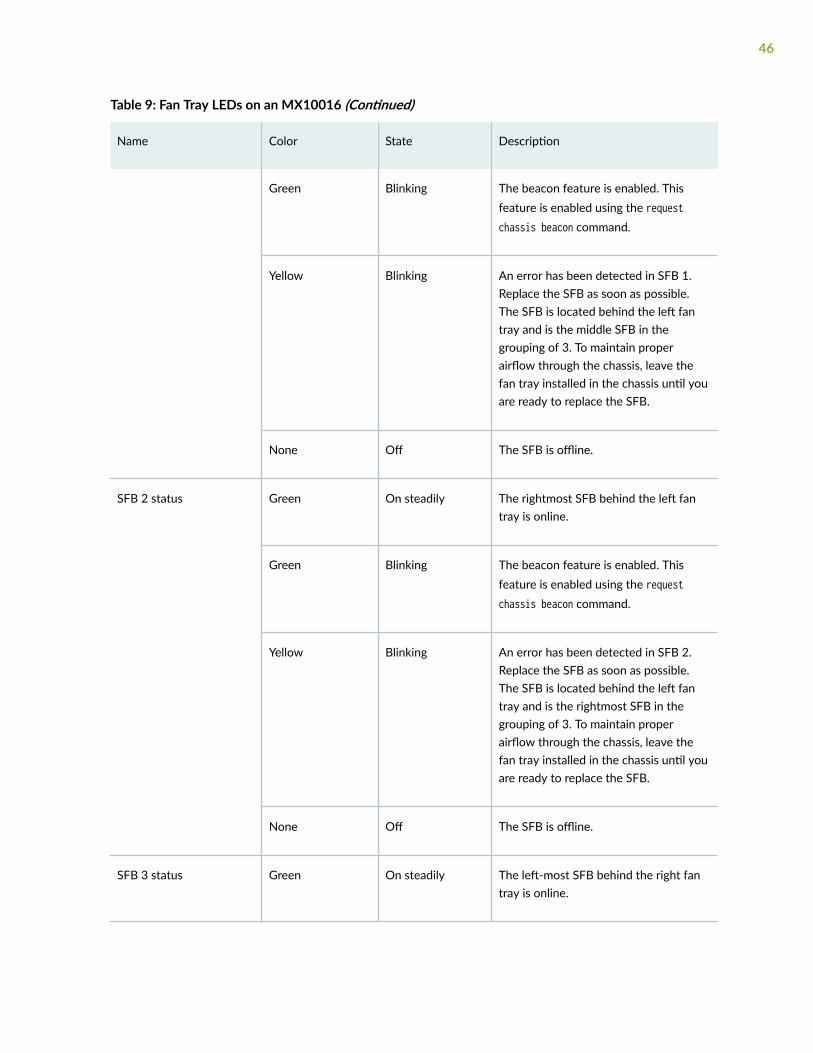
Table 9: Fan Tray LEDs on an MX10016 (Continued)
Name Color State Description
Green Blinking The beacon feature is enabled. Thisfeature is enabled using the requestchassis beacon command.
Yellow Blinking An error has been detected in SFB 1.Replace the SFB as soon as possible.The SFB is located behind the left fantray and is the middle SFB in thegrouping of 3. To maintain properairflow through the chassis, leave thefan tray installed in the chassis until youare ready to replace the SFB.
None Off The SFB is offline.
SFB 2 status Green On steadily The rightmost SFB behind the left fantray is online.
Green Blinking The beacon feature is enabled. Thisfeature is enabled using the requestchassis beacon command.
Yellow Blinking An error has been detected in SFB 2.Replace the SFB as soon as possible.The SFB is located behind the left fantray and is the rightmost SFB in thegrouping of 3. To maintain properairflow through the chassis, leave thefan tray installed in the chassis until youare ready to replace the SFB.
None Off The SFB is offline.
SFB 3 status Green On steadily The left-most SFB behind the right fantray is online.
46

Table 9: Fan Tray LEDs on an MX10016 (Continued)
Name Color State Description
Green Blinking The beacon feature is enabled. Thisfeature is enabled using the requestchassis beacon command.
Yellow Blinking An error has been detected in SFB 3.Replace the SFB as soon as possible.The SFB is located behind the right fantray and is the leftmost SFB in thegrouping of 3. To maintain properairflow through the chassis, leave thefan tray installed in the chassis until youare ready to replace the SFB.
None Off The SFB is offline.
SFB 4 status Green On steadily The center SFB behind the right fan trayis online.
Green Blinking The beacon feature is enabled. Thisfeature is enabled using the requestchassis beacon command.
Yellow Blinking An error has been detected in SFB 4.Replace the SFB as soon as possible.The SFB is located behind the right fantray and is the middle SFB in thegrouping of 3. To maintain properairflow through the chassis, leave thefan tray installed in the chassis until youare ready to replace the SFB.
None Off The SFB is offline.
SFB 5 status Green On steadily The right-most SFB behind the right fantray is online.
47
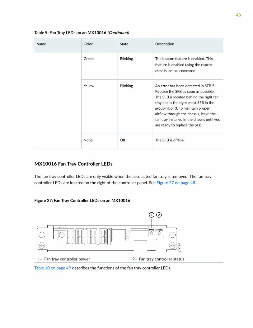
Table 9: Fan Tray LEDs on an MX10016 (Continued)
Name Color State Description
Green Blinking The beacon feature is enabled. Thisfeature is enabled using the requestchassis beacon command.
Yellow Blinking An error has been detected in SFB 5.Replace the SFB as soon as possible.The SFB is located behind the right fantray and is the right-most SFB in thegrouping of 3. To maintain properairflow through the chassis, leave thefan tray installed in the chassis until youare ready to replace the SFB.
None Off The SFB is offline.
MX10016 Fan Tray Controller LEDs
The fan tray controller LEDs are only visible when the associated fan tray is removed. The fan traycontroller LEDs are located on the right of the controller panel. See Figure 27 on page 48.
Figure 27: Fan Tray Controller LEDs on an MX10016
1— Fan tray controller power 2— Fan tray controller status
Table 10 on page 49 describes the functions of the fan tray controller LEDs.
48

Table 10: Fan Tray Controller LEDs on an MX10016
Name Color State Description
Fan controller power Green On steadily The fan tray controller has power and isoperating normally.
Yellow Blinking A power error has been detected in thefan tray controller. Replace the fan traycontroller as soon as possible. Tomaintain proper airflow through thechassis, leave the fan tray installed inthe chassis until you are ready toreplace the fan tray controller.
None Off The fan tray controller is not poweredon or is not receiving power.
Fan tray controller status Green On steadily The fan tray controller is online and isoperating normally.
Green Blinking The beacon feature is enabled. Thisfeature is enabled using the requestchassis beacon command.
Yellow Blinking An error has been detected in the fantray controller. Replace the fan traycontroller as soon as possible. Tomaintain proper airflow through thechassis, leave the fan tray installed inthe chassis until you are ready toreplace the fan tray controller.
None Off The fan tray controller is not receivingpower.
RELATED DOCUMENTATION
Removing and Installing MX10016 Cooling System Components | 178
49

MX10016 Power System
IN THIS SECTION
JNP10K-PWR-AC Power Supply | 51
JNP10K-PWR-AC2 Power Supply | 54
JNP10K-PWR-DC Power Supply | 56
JNP10K-PWR-DC2 Power Supply | 59
JNP10K-PWR-AC Power Supply LEDs | 62
JNP10K-PWR-AC2 Power Supply LEDs | 64
JNP10K-PWR-DC Power Supply LEDs | 66
JNP10K-PWR-DC2 Power Supply LEDs | 68
The MX10016 supports AC, DC, high-voltage alternating current (HVAC) and high-voltage direct current(HVDC) by offering the following power supplies:
• JNP10K-PWR-AC
• JNP10K-PWR-AC2
• JNP10K-PWR-DC
• JNP10K-PWR-DC2
CAUTION: Do not mix AC and DC power supplies in the same chassis.
All of the power supplies are hot-insertable and hot-removable, field-replaceable units (FRUs). In theMX10016, you can install up to 10 power supplies in the slots labeled PEM 0 through PEM 9 (top tobottom) located in the rear of the chassis. You can install the power supplies in any slot.
To determine whether your system has the standard power bus or the enhanced power bus, see Table 6on page 28. Table 11 on page 51 provides the specifications for these different power supplies.
50

Table 11: Power Supply Overview
JNP10K-PWR-AC
JNP10K-PWR-AC2 JNP10K-PWR-DC
JNP10K-PWR-DC2
Maximumoutput power
2700 W 5000 W or 5500 Wwhen set for high power(30-A); 3000 W whenset for low power (20-A)
2500 W 5500 W when set forhigh power (80-A) or4400 W when set for lowpower (60-A)
Inputs 2 (INP1, INP2) 2 (INP1, INP2) 2 (INPUT 1,INPUT 2)
4 (INPUT 1, INPUT 2)
Compatiblepower bus
Standard orenhanced
Standard or enhanced Standard orenhanced
Standard or enhanced
JNP10K-PWR-AC Power Supply
The JNP10K-PWR-AC power supplies are hot-insertable, hot-removable, field-replaceable units (FRUs).In an MX10016, you can install up to 10 power supplies in the slots labeled PSU 0 through PSU 9. Youcan install the power supplies in any slot.
The JNP10K-PWR-AC power supplies are 2700-W and support 200–240 VAC. The output is 12 VDC;the output power is 2700 W.
The AC power supply supports 200–240 VAC. The output is 12 VDC; the output power is 2700 W.
CAUTION: Do not mix AC and DC power supplies in the same chassis. AC and HVACcan coexist in the same chassis during the hot swap of AC for HVAC. Do not mix ACand HVAC power supplies in a running environment.
WARNING: The router is pluggable type A equipment installed in a restricted-accesslocation. It has a separate protective earthing terminal on the chassis that must beconnected to earth ground permanently to ground the chassis adequately and protectthe operator from electrical hazards.
51

CAUTION: Before you install the router, ensure that a licensed electrician has attachedan appropriate grounding lug to the grounding cable that you supply. Using a groundingcable with an incorrectly attached lug can damage the router.
NOTE: The base configuration of MX10016 routers are shipped with five power supplies. Coverare installed over the remaining power supply slots. You can add additional power supplies tobase configuration routers as necessary. For details about different router configurations, see"MX10016 Components and Configurations" on page 14.
Each JNP10K-PWR-AC power supply weighs approximately 6.8 lb (3.08 kg) and has two independent16-A rated AC inlets on the faceplate. Although each inlet provides sufficient input power to provide fulloutput, always connect to a dedicated AC power feed to provide redundancy. Only one power feed isoperational at a time.
The MX10016 routers employ automatic transfer switch (ATS) technology. The MX10016 power systemprovides 2nsource redundancy. If one power source fails, ATS routes the power supply to the alternatesource.
NOTE: For redundancy, always plug the two power cords from each power supply:
• INP1 into an uninterruptible power supply (UPS)
• INP2 into the public electricity supply
52

Each JNP10K-PWR-AC power supply has a power switch with international markings for on (|) and off(O), a fan, and four LEDs on the faceplate that indicate the status of the power supply. See Figure 28 onpage 53.
Figure 28: MX10016 AC Power Supply
Each JNP10K-PWR-AC power supply comes with two power cord retainers that hold the power cords inplace. See Figure 29 on page 54. Each power cord retainer has a clip and an adjustment nut. The endsof the clip hook into the bracket holes on each side of the AC appliance inlet on the faceplate. Theadjustment nut holds the power cord in the correct position. For instructions for installing the powercord retainers, see "Connecting AC Power to an MX10016" on page 161.
53
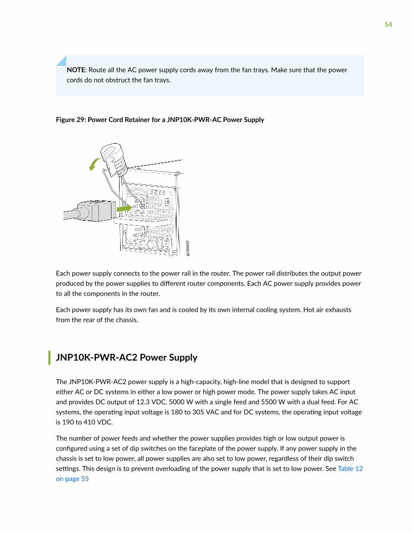
NOTE: Route all the AC power supply cords away from the fan trays. Make sure that the powercords do not obstruct the fan trays.
Figure 29: Power Cord Retainer for a JNP10K-PWR-AC Power Supply
Each power supply connects to the power rail in the router. The power rail distributes the output powerproduced by the power supplies to different router components. Each AC power supply provides powerto all the components in the router.
Each power supply has its own fan and is cooled by its own internal cooling system. Hot air exhaustsfrom the rear of the chassis.
JNP10K-PWR-AC2 Power Supply
The JNP10K-PWR-AC2 power supply is a high-capacity, high-line model that is designed to supporteither AC or DC systems in either a low power or high power mode. The power supply takes AC inputand provides DC output of 12.3 VDC, 5000 W with a single feed and 5500 W with a dual feed. For ACsystems, the operating input voltage is 180 to 305 VAC and for DC systems, the operating input voltageis 190 to 410 VDC.
The number of power feeds and whether the power supplies provides high or low output power isconfigured using a set of dip switches on the faceplate of the power supply. If any power supply in thechassis is set to low power, all power supplies are also set to low power, regardless of their dip switchsettings. This design is to prevent overloading of the power supply that is set to low power. See Table 12on page 55
54
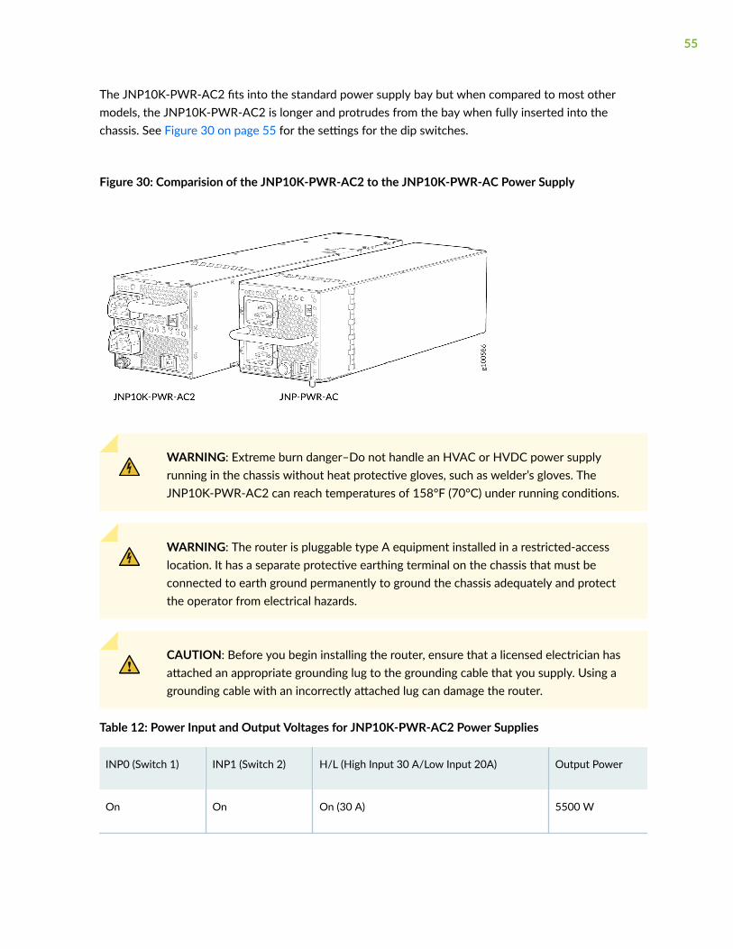
The JNP10K-PWR-AC2 fits into the standard power supply bay but when compared to most othermodels, the JNP10K-PWR-AC2 is longer and protrudes from the bay when fully inserted into thechassis. See Figure 30 on page 55 for the settings for the dip switches.
Figure 30: Comparision of the JNP10K-PWR-AC2 to the JNP10K-PWR-AC Power Supply
WARNING: Extreme burn danger–Do not handle an HVAC or HVDC power supplyrunning in the chassis without heat protective gloves, such as welder’s gloves. TheJNP10K-PWR-AC2 can reach temperatures of 158°F (70°C) under running conditions.
WARNING: The router is pluggable type A equipment installed in a restricted-accesslocation. It has a separate protective earthing terminal on the chassis that must beconnected to earth ground permanently to ground the chassis adequately and protectthe operator from electrical hazards.
CAUTION: Before you begin installing the router, ensure that a licensed electrician hasattached an appropriate grounding lug to the grounding cable that you supply. Using agrounding cable with an incorrectly attached lug can damage the router.
Table 12: Power Input and Output Voltages for JNP10K-PWR-AC2 Power Supplies
INP0 (Switch 1) INP1 (Switch 2) H/L (High Input 30 A/Low Input 20A) Output Power
On On On (30 A) 5500 W
55

Table 12: Power Input and Output Voltages for JNP10K-PWR-AC2 Power Supplies (Continued)
INP0 (Switch 1) INP1 (Switch 2) H/L (High Input 30 A/Low Input 20A) Output Power
On On Off (20 A) 3000 W
On Off On (30 A) 5000 W
Off On On (30 A) 5000 W
On Off Off (20 A) 2700 W
Off On Off (20 A) 2700 W
JNP10K-PWR-DC Power Supply
The MX10000 routers support three types of DC power supply modules:
• JNP10K-PWR-DC—A 2500-W, 12-VDC dual power supply.
• JNP10K-PWR-DC2—A 5500-W, 12-VDC quad input power supply. For details on this power supply,see "JNP10K-PWR-DC2 Power Supply" on page 59.
• JNP10K-PWR-AC2—An AC, high-voltage alternating current (HVAC,) or high-voltage direct current(HVDC) power supply. In high power mode, this power supply provides 12.3 V, 5000 W with a singlefeed and 5500 W with dual feeds. For details on this power supply, see "JNP10K-PWR-AC2 PowerSupply" on page 54.
56
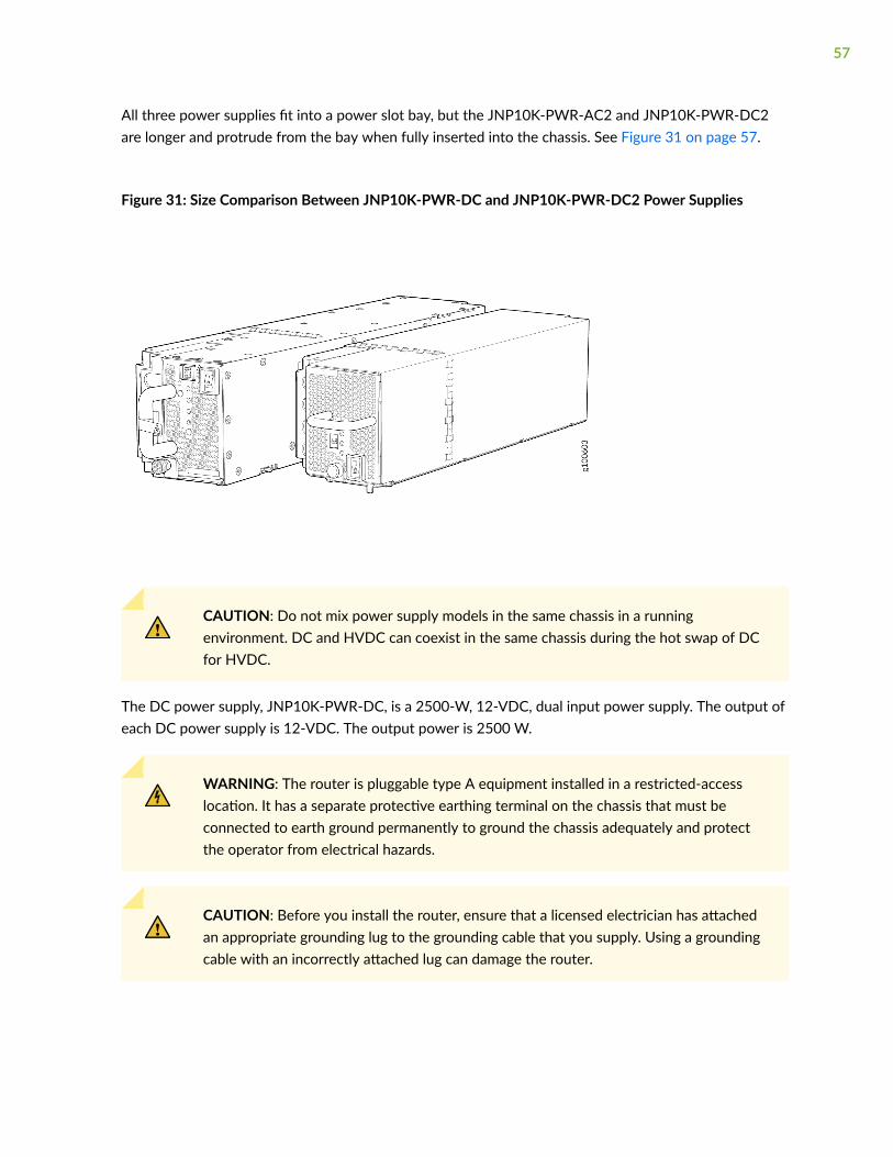
All three power supplies fit into a power slot bay, but the JNP10K-PWR-AC2 and JNP10K-PWR-DC2are longer and protrude from the bay when fully inserted into the chassis. See Figure 31 on page 57.
Figure 31: Size Comparison Between JNP10K-PWR-DC and JNP10K-PWR-DC2 Power Supplies
CAUTION: Do not mix power supply models in the same chassis in a runningenvironment. DC and HVDC can coexist in the same chassis during the hot swap of DCfor HVDC.
The DC power supply, JNP10K-PWR-DC, is a 2500-W, 12-VDC, dual input power supply. The output ofeach DC power supply is 12-VDC. The output power is 2500 W.
WARNING: The router is pluggable type A equipment installed in a restricted-accesslocation. It has a separate protective earthing terminal on the chassis that must beconnected to earth ground permanently to ground the chassis adequately and protectthe operator from electrical hazards.
CAUTION: Before you install the router, ensure that a licensed electrician has attachedan appropriate grounding lug to the grounding cable that you supply. Using a groundingcable with an incorrectly attached lug can damage the router.
57

NOTE: DC power supplies are shipped only in the redundant configuration of MX10016 routers.For details about different chassis configurations, see "MX10016 Components andConfigurations" on page 14.
Each JNP10K-PWR-DC power supply weighs approximately 6 lb (2.7 kg) and has two independent pairsof DC input lugs (Input 1, RTN, –48V/–60V and Input 2, RTN, –48V/–60V) on the faceplate of thepower supply. Each inlet requires a dedicated DC power feed. Although each inlet provides sufficientinput power to provide full output, always connect to a dedicated DC power feed to provideredundancy. Only one power feed is operational at a time.
DC power models employ an electronic A-B input selection. The MX10016 power system provides 2Nsource redundancy. If one power source fails, the electronic A-B input selection routes the power supplyto the alternate source.
Each JNP10K-PWR-DC power supply has a power switch with international markings for on (|) and off(O), a fan, and four LEDs on the faceplate that indicate the status of the power supply. See Figure 32 onpage 58.
Figure 32: JNP10K-PWR-DC Power Supply
58

NOTE: The JNP10K-PWR-DC power supply requires a dedicated circuit breaker for each inputDC feed. The chosen breaker should be sized to deliver 60 A of input current.
Each power supply connects to the combined power rail in an MX10016 router. The power raildistributes the output power produced by the power supplies to different router components. Each DCpower supply provides power to all the components in the router.
NOTE: Route all the DC power supply cords away from the fan trays. Make sure that the powercords do not obstruct the fan trays.
A DC power supply can operate with only one input DC feed connected. The Routing and Control Board(RCB) enables only the components for which sufficient power is available.
Each DC power supply has its own fan and is cooled by its own internal cooling system. The airflow isfrom the front of the power supply to the back. Hot air exhausts from the rear of the chassis.
NOTE: Route all the DC power supply cords away from the fan trays. Make sure that the powercords do not obstruct the fan trays.
JNP10K-PWR-DC power supplies can use the standard bus or the enhanced bus.
A JNP10K-PWR-DC power supply can operate with only one input DC feed connected. The RoutingControl Board only enables the components for which sufficient power is available.
Each JNP10K-PWR-DC power supply has its own fan and is cooled by its own internal cooling system.The airflow is from the front of the power supply to the back. Hot air exhausts from the rear of thechassis.
JNP10K-PWR-DC2 Power Supply
The JNP10K-PWR-DC2 power supply (See Figure 33 on page 60) provides two power supplies in asingle housing that accepts either 60 A or 80 A using four redundant input power feeds. PS_0 and PS_1each have redundant input feeds: A0 and/or B0 for PS_0 and A1 and/or B1 for PS_1. The input isconfigured using a set of dip switches on the power supply faceplate. The output is dependant on thesettings of these dip switches. See Table 13 on page 60.
59

Table 13: Power Input and Output Voltages for JNP10K-PWR-DC2 Power Supplies
INP0 (Switch 1) INP1 (Switch 2) H/L (High Input 80 A/Low Input 60A) Output Power
On On On (80 A) 5500 W
On On Off (60 A) 4400 W
On Off On (80 A) 2750 W
Off On On (80 A) 2750 W
On Off Off (60 A) 2200 W
Off On Off (60 A) 2200 W
Figure 33: JNP10K-PWR-DC2 Power Supply
CAUTION: Do not mix power supplies models in the same chassis in a runningenvironment. DC and HVDC can coexist in the same chassis during the hot swap of DCfor HVDC.
To determine whether your system has the standard power bus or the enhanced power bus, see Table 6on page 28.
60
WARNING: The router is pluggable type A equipment installed in a restricted-accesslocation. It has a separate protective earthing terminal on the chassis that must beconnected to earth ground permanently to ground the chassis adequately and protectthe operator from electrical hazards.
CAUTION: Before you begin installing the router, ensure that a licensed electrician hasattached an appropriate grounding lug to the grounding cable that you supply. Using agrounding cable with an incorrectly attached lug can damage the router.
NOTE: DC power supplies are shipped only in the redundant configuration of MX10016 routers.For details about different chassis configurations, see "MX10016 Components andConfigurations" on page 14.
JNP10K-PWR-DC2 models can use the standard bus or the enhanced bus. The enhanced bus supportsthe full 5500 W available from the JNP10K-PWR-DC2. The standard bus provides 3000 W for powerbudget from the power management software. To determine whether your system has the standardpower bus or the enhanced power bus, see Table 6 on page 28.
61
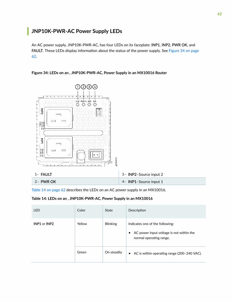
JNP10K-PWR-AC Power Supply LEDs
An AC power supply, JNP10K-PWR-AC, has four LEDs on its faceplate: INP1, INP2, PWR OK, andFAULT. These LEDs display information about the status of the power supply. See Figure 34 on page62.
Figure 34: LEDs on an , JNP10K-PWR-AC, Power Supply in an MX10016 Router
1— FAULT 3— INP2–Source input 2
2— PWR OK 4— INP1–Source input 1
Table 14 on page 62 describes the LEDs on an AC power supply in an MX10016.
Table 14: LEDs on an , JNP10K-PWR-AC, Power Supply in an MX10016
LED Color State Description
INP1 or INP2 Yellow Blinking Indicates one of the following:
• AC power input voltage is not within thenormal operating range.
Green On steadily • AC is within operating range (200–240 VAC).
62

Table 14: LEDs on an , JNP10K-PWR-AC, Power Supply in an MX10016 (Continued)
LED Color State Description
Dark Unlit The power supply is switched off.
PWR OK Green On steadily • AC power output is within normal operatingrange.
Yellow Blinking • AC power output is out of the normaloperating range.
FAULT Unlit Off • The power supply is functioning normally.
Red On steadily • The power supply has failed and must bereplaced.
• Only one input is powered and the enableswitch for the input that is not powered is setto ON. See "MX10016 Power System" onpage 50 for more information about theenable switches.
NOTE: If the INP1 or INP2 LED and the PWR OK LED are unlit, the AC power cord is notinstalled properly or the power supply has failed.
If the INP1 or INP2 LED is lit and the PWR OK LED is unlit, the AC power supply is not installedproperly or the power supply has an internal failure.
63
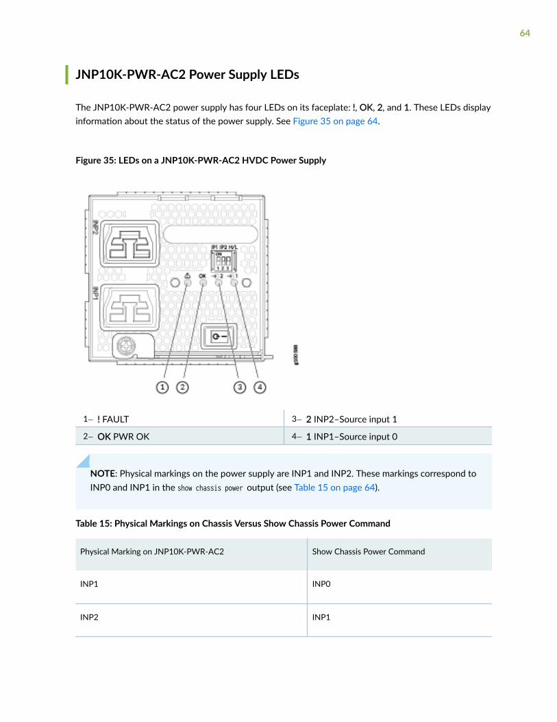
JNP10K-PWR-AC2 Power Supply LEDs
The JNP10K-PWR-AC2 power supply has four LEDs on its faceplate: !, OK, 2, and 1. These LEDs displayinformation about the status of the power supply. See Figure 35 on page 64.
Figure 35: LEDs on a JNP10K-PWR-AC2 HVDC Power Supply
1— ! FAULT 3— 2 INP2–Source input 1
2— OK PWR OK 4— 1 INP1–Source input 0
NOTE: Physical markings on the power supply are INP1 and INP2. These markings correspond toINP0 and INP1 in the show chassis power output (see Table 15 on page 64).
Table 15: Physical Markings on Chassis Versus Show Chassis Power Command
Physical Marking on JNP10K-PWR-AC2 Show Chassis Power Command
INP1 INP0
INP2 INP1
64

Table 16 on page 65 describes the LEDs on a JNP10K-PWR-AC2 power supply.
Table 16: Interpreting JNP10K-PWR-AC2 LEDs
LED Color State Description
INP1 or INP0 in CLIoutput
Yellow Blinking The input voltage is present, but is not withinnormal operating range.
Green Solid The input voltage is present and within normaloperating range.
Unlit Off The power supply is switched off; voltage is zero.
INP2 or INP1 in CLIoutput
Yellow Blinking The input voltage is present, but is not withinnormal operating range.
Green Solid The input voltage is present and within normaloperating range.
Unlit Off The power supply is switched off; voltage is zero.
OK Green Solid The power supply output is within normaloperating range.
Yellow Blinking The power supply output is out of the powerlimits or is over-current position.
! Red Solid Power supply has failed and must be replaced.
Unlit Off Power supply is functioning normally.
65

JNP10K-PWR-DC Power Supply LEDs
The JNP10K-PWR-DC power supply has four LEDs on its faceplate: INP1, INP1, PWR OK, and FAULT.These LEDs display information about the status of the power supply. See Figure 36 on page 66.
Figure 36: LEDs on a JNP10K-PWR-DC Power Supply in an MX10016
1— INP1–Source input 1 3— PWR OK
2— INP2–Source input 2 4— FAULT
Table 17 on page 66 describes the LEDs in on the JNP10K-PWR-DC power supply in an MX10016chassis.
Table 17: LEDs on a DC Power Supply in an MX10016
LED Color State Description
INP1 or INP2 Yellow Blinking Indicates that the DC power input voltage is notwithin normal operating range.
Green On Steadily DC power is within the operating range (-40 VDCto -72 VDC).
Unlit Off The power supply is switched off.
66

Table 17: LEDs on a DC Power Supply in an MX10016 (Continued)
LED Color State Description
PWR OK Green On Steadily DC power output is within the normal operatingrange.
Yellow Blinking DC power output is out of the normal operatingrange.
FAULT Red On Steadily The power supply has failed and must bereplaced.
Unlit Off • The power supply is functioning normally.
• Only one input is powered and the enableswitch for the input that is not powered is setto ON. See "Connecting DC Power to anMX10016" on page 162 for more informationabout the enable switches.
NOTE: If the INP1 or INP2 and the PWR OK LED are unlit, the power cords are not installedproperly or the power supply has failed.
If the INP1 or INP2 LED is lit green and the PWR OK LED is unlit, the power supply is notinstalled properly or the power supply has an internal failure.
If the FAULT LED is blinking, add a power supply to balance the power demand and supply.
67

JNP10K-PWR-DC2 Power Supply LEDs
A JNP10K-PWR-DC2 power supply module has four LEDs on its faceplate: 1, 2, OK, and the symbol forfault, !. These LEDs display information about the status of the power supply. See Figure 37 on page68.
Figure 37: LEDs on a JNP10K-PWR-DC2 Power Supply
1— !–FAULT 3— 2–Source input 1
2— OK–Power okay 4— 1–Source input 0
You can find out the version of the firmware installed in the power supply from the output of show systemfirmware command. Table 18 on page 68 describes the LEDs on a JNP10K-PWR-DC2 power supply ifthe firmware installed in the power supply is 300.300.208.208.304 or higher. Table 19 on page 70describes the LEDs on a JNP10K-PWR-DC2 power supply if the firmware installed in the power supplyis lower than 300.300.208.208.304.
Table 18: LEDs on a JNP10K-PWR-DC2 Power Supply (with 300.300.208.208.304 or higher firmwareinstalled in it)
Feed 0 Feed 1 State of thePower SupplySwitch
LED 1 LED 2 OK LED ! LED
Off Off Off Orange Orange Off Red
68

Table 18: LEDs on a JNP10K-PWR-DC2 Power Supply (with 300.300.208.208.304 or higher firmwareinstalled in it) (Continued)
Feed 0 Feed 1 State of thePower SupplySwitch
LED 1 LED 2 OK LED ! LED
A or B Off Off Green—Blinking
Orange Off Red
A and B Off Off Green Orange Off Red
Off A or B Off Orange Green—Blinking
Off Red
A or B A or B Off Green—Blinking
Green—Blinking
Off Red—Blinking
A and B A or B Off Green Green—Blinking
Off Red—Blinking
Off A and B Off Orange Green Off Red
A or B A and B Off Green—Blinking
Green Off Red—Blinking
A and B A and B Off Green Green Off Off
Off Off On Orange Orange Off Red
A or B Off On Green—Blinking
Orange Green Red
A and B Off On Green Orange Green Red
Off A or B On Orange Green—Blinking
Green Red
69

Table 18: LEDs on a JNP10K-PWR-DC2 Power Supply (with 300.300.208.208.304 or higher firmwareinstalled in it) (Continued)
Feed 0 Feed 1 State of thePower SupplySwitch
LED 1 LED 2 OK LED ! LED
A or B A or B On Green—Blinking
Green—Blinking
Green Red—Blinking
A and B A or B On Green Green—Blinking
Green Red—Blinking
Off A and B On Orange Green Green Red
A or B A and B On Green—Blinking
Green Green Red—Blinking
A and B A and B On Green Green Green Off
Table 19: LEDs on a JNP10K-PWR-DC2 Power Supply (with firmware lower than 300.300.208.208.304installed in it)
LED Color State Description
1 (INP0 in CLI output) or2 (INP1 in CLI output)
Yellow Blinking Indicates the DC power input voltage is not withinnormal operating range.
Green Solid DC power is within operating range (-40 VDC to-72 VDC).
Unlit Off The power supply is switched off.
OK Green Solid DC power output is within normal operatingrange.
Yellow Blinking The output is out of the limits.
70
Table 19: LEDs on a JNP10K-PWR-DC2 Power Supply (with firmware lower than 300.300.208.208.304installed in it) (Continued)
LED Color State Description
! Red Solid Power supply has failed and must be replaced.
Unlit Off Power supply is functioning normally. Or, only oneinput is powered and the enable switch for theinput that is not powered is set to ON. See"Connecting DC Power to an MX10016" on page162 for more information on the enable switches.
NOTE: If the 1 or 2 and the OK LED are unlit, the power cables are not installed properly or thepower supply has failed.
If the 1 or LED is lit green and the OK LED is unlit, the power supply is not installed properly orthe power supply has an internal failure.
If the ! LED is blinking, add a power supply to balance the power demand and supply.
RELATED DOCUMENTATION
MX10016 Power Planning | 100
MX10016 Routing and Control Board
IN THIS SECTION
MX10016 Routing and Control Board Description | 72
MX10016 Routing and Control Board LEDs | 74
71
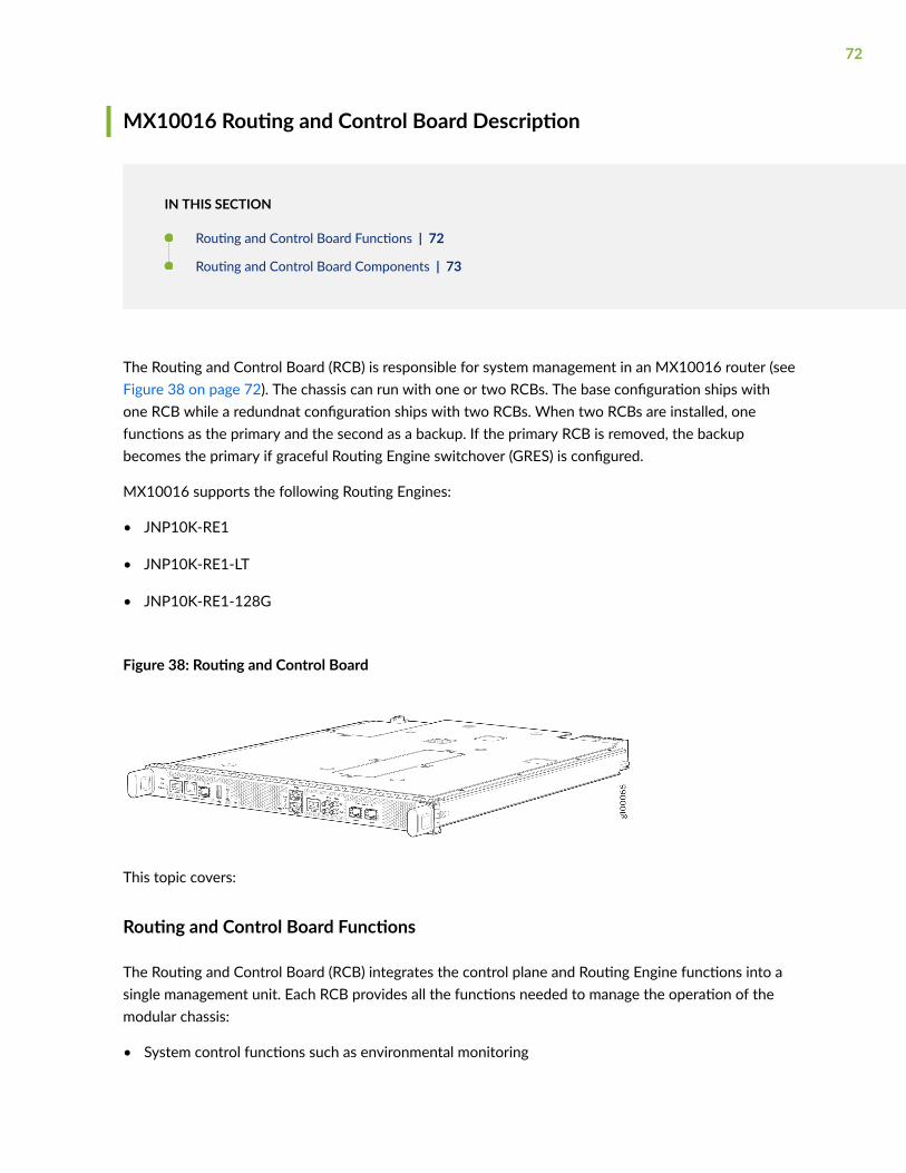
MX10016 Routing and Control Board Description
IN THIS SECTION
Routing and Control Board Functions | 72
Routing and Control Board Components | 73
The Routing and Control Board (RCB) is responsible for system management in an MX10016 router (seeFigure 38 on page 72). The chassis can run with one or two RCBs. The base configuration ships withone RCB while a redundnat configuration ships with two RCBs. When two RCBs are installed, onefunctions as the primary and the second as a backup. If the primary RCB is removed, the backupbecomes the primary if graceful Routing Engine switchover (GRES) is configured.
MX10016 supports the following Routing Engines:
• JNP10K-RE1
• JNP10K-RE1-LT
• JNP10K-RE1-128G
Figure 38: Routing and Control Board
This topic covers:
Routing and Control Board Functions
The Routing and Control Board (RCB) integrates the control plane and Routing Engine functions into asingle management unit. Each RCB provides all the functions needed to manage the operation of themodular chassis:
• System control functions such as environmental monitoring
72

• Routing Layer 2 and Layer 3 protocols
• Communication to all components such as line cards, Switch Fabric Boards (SFBs), and power andcooling
• Transparent clocking
• Alarm and logging functions
Routing and Control Board Components
Each Routing and Control Board (RCB) consists of the following internal components:
• CPU—Runs Junos OS to maintain the routing tables and routing protocols.
• EEPROM—Stores the serial number of the Routing Engine.
• DRAM—Provides storage for the routing and forwarding tables and for other Routing Engineprocesses.
• One 10-Gigabit Ethernet— Connects the Routing Engine and Switch Fabric Board.
• One USB port—Provides a removable media interface through which you can install Junos OSmanually. Junos OS supports USB versions 3.0, 2.0, and 1.1.
• Management ports—Two ports, one copper (RJ-45) port and one SFP port, provide access tomanagement devices. Use only one of the two management ports at a time.
Use an RJ-45 connector for the copper port.
Use a fiber optic connector for the SFP port.
Do not use copper SFP or SFP-T modules in the SFP port as they are not supported.
• RESET button—When pressed, reboots the RCB as detailed below:
• When pressed for less than 5 seconds for diagnostic purposes, the RCB does not reset. The pressevent is logged in the RCB FPGA register.
• When pressed for greater than 5 seconds but less than 10 seconds, the RCB reboots and thereset-reason logs the button press event.
• When pressed for greater than 10 seconds, the RCB reboots with an option for BIOS recovery.
• LEDs—Provide status of the Routing Engine.
• Online/Offline Button—When the RCB is online and if the button is pressed for more than 4 seconds,the RCB goes offline. When the RCB is offline and if the button is pressed more than 4 seconds, theRCB starts booting.
73

For specific information about Routing Engine components (for example, the amount of DRAM), issuethe show vmhost hardware command.
Figure 39: Routing and Control Board Faceplate
1— Handles 7— Reset button
2— BITS-0 clock port 8— Online/Offline button
3— GPS clock ports 9— USB port
4— XGE-0 and XGE-1 Juniper Control System(JCS) ports
10— Management (MGMT) ports
5— ToD—Time-of-day (TOD) port 11— Console (CONSOLE) port
6— BITS-1 clock port
MX10016 Routing and Control Board LEDs
Figure 40 on page 74 shows the LEDs on the Routing and Control Boards (JNP10K-RE1).
Figure 40: Routing and Control Board LEDs
1— RCB status panel LEDs—PWR, STS, andMASTER
3— Clock LEDs—BITS-0, and BITS-1
2— Solid State Disk (SSD) LEDs—DISK1 andDISK2
Table 20 on page 75 describes the LEDs on the RCB status panel.
74

Table 20: Routing and Control Board Status LEDs
LED Color State Description
PWR Green On steadily The RCB is receiving adequate power.
Yellow Blinking An error has been detected in the RCB.
Unlit Off The RCB is not powered up.
STS Green On steadily The RCB is online and functioning correctly.
Green Blinking The beacon feature is enabled.
Yellow On steadily The RCB is booting.
Yellow Blinking An error has been detected in the RCB.
Dark Unlit The power supply is switched off.
MST Green On steadily The RCB is the primary.
Dark Unlit The RCB is the backup.
Figure 41 on page 75 shows the management port LEDs on the RCB.
Figure 41: Management Port LEDs on an RCB
1— Status LED (RJ-45) 3— LINK LED
75

2— Activity LED (RJ-45)
Table 21 on page 76 describes the RJ-45 management port and SFP LEDs.
Table 21: RJ-45 Management Port LEDs on the Routing and Control Board
LED Color State Description
Activity/Status LED Unlit Off The port speed is 10 MB.
Green Blinking The port speed is100 MB.
Green On steadily The port speed is1000 MB.
LINK Unlit Off No link is established,there is a fault, or the linkis down.
Green On steadily A link is established.
Blinking There is link activity.
Yellow Blinking or flickering The beacon feature isenabled.
Table 22 on page 76 describes the JCS port LEDs.
Table 22: JCS Port LEDs on the Routing and Control Board
LED Color State Description
LINK LEDs for JCS Ports (XGE0 and XGE1) Unlit Off No transceiver is present.
Green On steadily A link is established. The interfaceis up.
76

Table 22: JCS Port LEDs on the Routing and Control Board (Continued)
LED Color State Description
Green Blinking orflickering
The beacon feature is enabled.
Yellow Blinking An error has occurred.
Table 23 on page 77 describes the LEDs for the secondary SATA drives.
Table 23: Routing and Control Board SSD Status LEDs
LED Color State Description
DISK1 and DISK2 Green On steadily A SATA drive is present.
Green Blinking The drive is active.
Yellow On steadily The drive is active.
Dark Unlit A drive is not installed.
RELATED DOCUMENTATION
Removing and Installing Routing and Control Boards
MX10016 Switch Fabric Board
IN THIS SECTION
MX10016 Switch Fabric Board Description | 79
77

Switch Fabric Board LEDs | 82
Switch Fabric Boards (SFBs) create the switch fabric for the MX10016. Each MX10016 contains six SFBsthat are installed vertically, mid-chassis, between the line cards and the RCBs in the front and the fantrays in the rear. When all six SFBs are installed, the MX10016 has a net switching capacity of 96 Tbps.
78
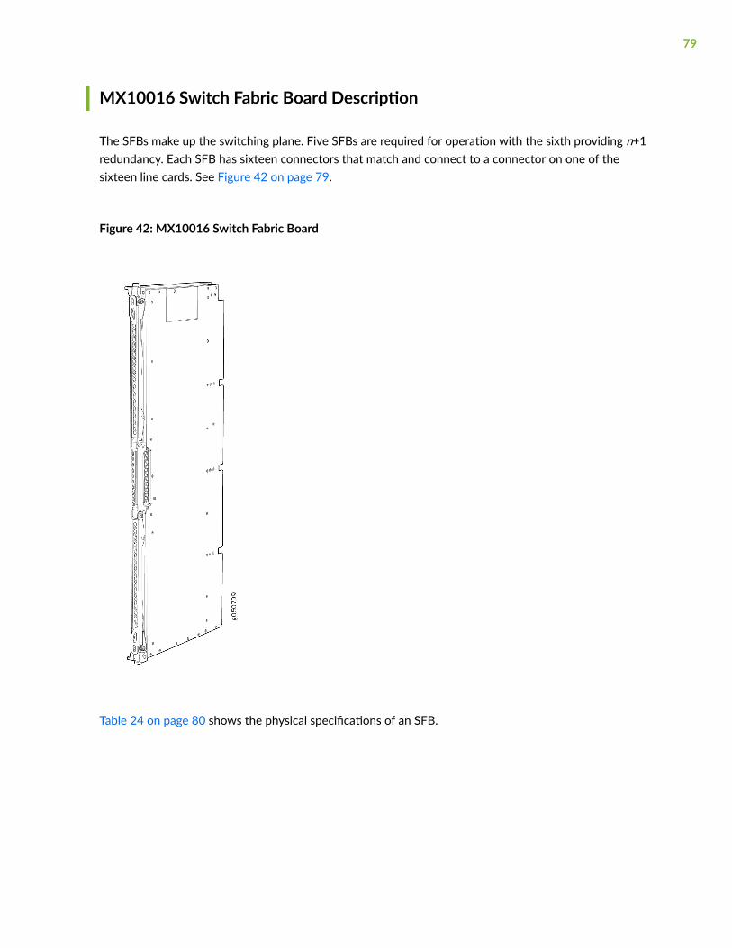
MX10016 Switch Fabric Board Description
The SFBs make up the switching plane. Five SFBs are required for operation with the sixth providing n+1redundancy. Each SFB has sixteen connectors that match and connect to a connector on one of thesixteen line cards. See Figure 42 on page 79.
Figure 42: MX10016 Switch Fabric Board
Table 24 on page 80 shows the physical specifications of an SFB.
79

Table 24: Dimensions of an SFB
Specification Value
Height 34.6 in. (87.88 cm)
Width 1.8 in. (4.57 cm)
Depth 10.4 in. (26.42 cm)
Weight 35.2 lb (15.97 kg)
80

SFBs are hot-removable and hot-insertable field-replaceable units (FRUs). They are not visible from theoutside of the router chassis. You must remove one of the fan trays in order to view the SFBs. The SFBsare numbered from left to right SFB0 to SFB5. See Figure 43 on page 81.
Figure 43: SFBs Installed in an MX10016
1— Fan tray controllers 2— Switch Fabric Boards
81

Switch Fabric Board LEDs
The Switch Fabric Board (SFB) has two status LEDs at the top of each board. See Figure 44 on page 82.
Figure 44: Switch Fabric Board LEDs
Table 25 on page 82 describes the functions of these LEDs.
Table 25: SFB LEDs
Label Color State Description
PWR Green On steadily The SFB is receiving power.
Yellow Blinking A power fault has occurred.
Unlit Off The SFB is either offline or not receiving power.
STAT Green On steadily The SFB is online and functioning normally.
Green Blinking The beacon feature is enabled.
82

Table 25: SFB LEDs (Continued)
Label Color State Description
Yellow On steadily The SFB has failed.
Unlit Off The fan tray controller is facing a power problem.
RELATED DOCUMENTATION
How to Handle and Store an MX10016 Switch Fabric Board | 229
Removing and Installing MX10016 Switch Fabric Boards | 229
MX10K-LC2101 Line Card
The MX10K-LC2101 line card is a fixed configuration MPC and it does not contain separate slots forModular Interface Cards (MICs). The MX10008 routers support eight MX10K-LC2101 MPCs.The linecard provides a maximum bandwidth of 2.4Tbps and has six Packet Forwarding Engines, each providinga maximum bandwidth of up to 400 Gbps.
1— OFFLINE button 3— Lane LEDs
2— OK/FAIL LED 4— Port LEDs
Software release Junos OS Release 18.2R1 and later
83
Description • Weight: 31.57 lb (14.32 kg)
• Model number: JNP10K-LC2101
• Name in the CLI: JNP10K-LC2101
• Dimensions: Height = 1.89 in. (48.01 mm), Width = 17.2 in (436.88 mm), Depth = 19.05 in. (484 mm) (ExcludingFRU Ejector)
Hardware features • Fixed-configuration MPC with 10-Gbps, 40-Gbps, and 100-Gbps port speeds.
• All the ports are multi-rate ports. Each port is capable of supporting either 100 Gbps or 40 Gbps or 10 Gbps(4x10-Gbps with breakout cable).
• Line-rate throughput of up to 2.4 Tbps.
• Six Packet Forwarding Engines, each providing a maximum bandwidth of 400 Gbps.
• EA chipsets for increased scaling for bandwidth, subscribers, and services.
• Supports the Switch Fabric Boards, JNP10008-SF and JNP10016-SF.
• Supports maximum transmission units (MTUs) from 256 bytes through 16,000 bytes for transit traffic, and from256 bytes through 9,500 bytes for host bound packets.
Software features • Supports rate selectability at the port level.
• By default, the ports are configured as 10-Gigabit Ethernet ports.
• Optical diagnostics and related alarms.
Power requirements Line-rate throughput of 2.4 Tbps:
• Power consumption at different temperatures:
25° C: 1335 W
40° C: 1425 W
84
LEDs OK/FAIL LED:
• Steady green—MPC is functioning normally.
• Yellow—MPC has failed.
Port LED—Link
• Off—Port is not enabled.
• Green—Port link is up with no alarms or failures.
• Red—Port link is down with alarms.
NOTE: When a QSFP+ port is configured for the 10-Gigabit mode with a breakout cable, the link status for the 10-Gigabit port is indicated with the addition of four LEDs provided on the line card. The lane LEDs for thecorresponding port indicates the port status.
Like the port status LED, each individual lane LED support four states as: OFF, AMBER, GREEN, RED. See MPC andMIC Lane LED Scheme Overview for more details.
For the 40-Gigabit mode the lane number LED is not applicable. The port LED indicates the port status, irrespectiveof whichever lane number LED is ON.
Cables andconnectors
TIP: You can use the Hardware Compatibility Tool to find information about the pluggable transceivers supportedon your Juniper Networks device.
The list of supported transceivers for the MX Series is located at MX Series Supported Transceivers.
MX10K-LC480 Line Card
The MX10K-LC480 (Model number: JNP10K-LC480) is a fixed-configuration line card with 48 SFP/SFP+ports. Each port supports a speed of 10 Gbps or 1 Gbps, providing the line card a maximum bandwidthof 480 Gbps. The MX10K-LC480 has two Packet Forwarding Engines, each providing a maximumbandwidth of 240 Gbps. The line card plugs into the MX10008 and MX10016 routers horizontally at thefront of the chassis.
85
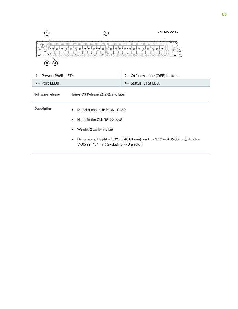
1— Power (PWR) LED. 3— Offline/online (OFF) button.
2— Port LEDs. 4— Status (STS) LED.
Software release Junos OS Release 21.2R1 and later
Description • Model number: JNP10K-LC480
• Name in the CLI: JNP10K-LC480
• Weight: 21.6 lb (9.8 kg)
• Dimensions: Height = 1.89 in. (48.01 mm), width = 17.2 in (436.88 mm), depth =19.05 in. (484 mm) (excluding FRU ejector)
86

Hardware features • Fixed-configuration line card with 10-Gbps and 1-Gbps port speeds
• Line-rate throughput of up to 480 Gbps
• Two Packet Forwarding Engines, each providing a maximum bandwidth of 240 Gbps
• EA chipset for increased scaling for bandwidth, subscribers, and services
• Supports the Switch Fabric Boards JNP10008-SF and JNP10016-SF
• Interoperates with the JNP10K-LC2101 line card
• Operates with the following Routing and Control Boards: JNP10K-RE1, JNP10K-RE1-128, and JNP10K-RE1-LT
• Operates with the following power supplies and fan trays:
• JNK10K-PWR-AC or JNK10K-PWR-DC with the JNP10008-FAN or JNP10016-FAN.
• JNP10K-PWR-AC2 or JNP10K-PWR-DC2 with JNP10008-FAN2 or JNP10016-FAN2.
In both of the above configurations, the MX10K-LC480 line card adheres to thecomplete NEBS compliance (NEBS GR63-CORE, GR1089-CORE, and SR3580compliance).
• Meets the full NEBS requirement on both the MX10008 and the MX10016 routers
• Supports a maximum transmission unit (MTU) ranging from 256 bytes through16,000 bytes for transit traffic, and from 256 bytes through 9000 bytes for host-bound packets
Software features • Default port configuration of 10GbE.
• Supports optics diagnostics and related alarms
87

Power requirements • Power consumption at different temperatures when all ports are configured in 10-Gbps speed:
25° C: 420 W (without MACSec), 430 W (with MACSec)
40° C: 430 W (without MACSec), 450 W (with MACSec)
55° C: 450 W (without MACSec), 480 W (with MACSec)
• Power consumption at different temperatures when all ports are configured in 1-Gbps speed:
25° C: 360 W (without MACSec), 370 W (with MACSec)
40° C: 370 W (without MACSec), 390 W (with MACSec)
55° C: 390 W (without MACSec), 420 W (with MACSec)
LEDs PWR LED
• Steady green—Line-card power is ok.
• Steady red—Line-card power-on has failed.
• Off—Line card is not receiving power.
STS LED
• Steady green (blinking green when the beacon or the port location is on)—Line card isonline.
• Blinking green—The line card is booting.
• Steady red (blinking red when the beacon or the port location is on)—Line card isfaulty or an alarm has been raised.
• Off—Line card is disabled or offline.
Port LED
• Off—Port does not have any transceiver module.
• Steady green (blinking green when the beacon or the port location is on)—Port link isup with no alarms or failures.
• Steady amber (blinking amber when the beacon or the port location is on)—Port linkis down because the port is disabled through the CLI or the port encountered errorssuch as loss of signal, local fault, or remote fault.
88

Cables andconnectors
TIP: You can use the Hardware Compatibility Tool to find information about thepluggable transceivers that your Juniper Networks device supports.
See the list of supported transceivers for the MX Series at MX Series SupportedTransceivers.
MX10K-LC480 supports 1-Gbps Copper SFP modules in all the ports. You must useshielded RJ45 cables with 1-Gbps copper SFP modules.
You must install the MX10K-LC480 line card in the MX10008 and MX10016 routersalong with the front panel with filter to meet the EMI Class-A emission standards.
The following applies to a router (MX10008 or MX10016) installed with the front panel:
• We recommend that you use only 16 ports per line card with copper SFP modules -the last 8 ports on the MIC0 (0/16 through 0/23) and the first 8 ports on the MIC1(1/0 through 1/7).
• The MX10008 router supports a maximum of 128 copper SFP modules of 1 Gbpscapacity.
• The MX10016 router supports a maximum of 192 copper SFP modules of 1 Gbpscapacity.
NOTE: The 1-Gbps copper SFP modules on the MX10K-LC480 line card do not supportPrecision Time Protocol (PTP) and Synchronous Ethernet functionality.
89

2CHAPTER
Site Planning, Preparation, andSpecifications
MX10016 Site Preparation Overview | 91
MX10016 Power Planning | 100
MX10016 Transceiver and Cable Specifications | 122
MX10016 Alarm and Management Cable Specifications and Pinouts | 128
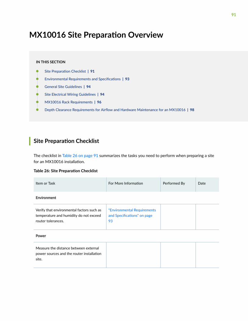
MX10016 Site Preparation Overview
IN THIS SECTION
Site Preparation Checklist | 91
Environmental Requirements and Specifications | 93
General Site Guidelines | 94
Site Electrical Wiring Guidelines | 94
MX10016 Rack Requirements | 96
Depth Clearance Requirements for Airflow and Hardware Maintenance for an MX10016 | 98
Site Preparation Checklist
The checklist in Table 26 on page 91 summarizes the tasks you need to perform when preparing a sitefor an MX10016 installation.
Table 26: Site Preparation Checklist
Item or Task For More Information Performed By Date
Environment
Verify that environmental factors such astemperature and humidity do not exceedrouter tolerances.
"Environmental Requirementsand Specifications" on page93
Power
Measure the distance between externalpower sources and the router installationsite.
91

Table 26: Site Preparation Checklist (Continued)
Item or Task For More Information Performed By Date
Calculate the power consumption andrequirements.
"MX10016 Power Planning" onpage 100
Rack
Verify that your rack meets the minimumrequirements for the installing the router.
"MX10016 RackRequirements" on page 96
Plan rack location, including requiredspace clearances.
"Depth ClearanceRequirements for Airflow andHardware Maintenance for anMX10016" on page 98
Secure the rack to the floor and buildingstructure.
Cables
Acquire cables and connectors:
• Determine the number of cablesneeded based on your plannedconfiguration.
• Review the maximum distance allowedfor each cable. Choose the length ofthe cable based on the distancebetween the hardware componentsbeing connected.
The list of supportedtransceivers for the MX10016line cards is located atMX10016 Transceivers andSpecifications
Plan the cable routing and management.
92

Environmental Requirements and Specifications
The MX10016 router must be installed in a four-post rack. It must be housed in a dry, clean, well-ventilated, and temperature-controlled environment.
Follow these environmental guidelines:
• The site must be as dust-free as possible, because dust can clog air intake vents and filters, reducingthe efficiency of the router cooling system.
• Maintain ambient airflow for normal router operation. If the airflow is blocked or restricted, or if theintake air is too warm, the router might overheat, causing the router temperature monitor to shutdown the device to protect the hardware components.
Table 27 on page 93 provides the required environmental conditions for normal router operation.
Table 27: Environmental Tolerances
Description Tolerance
Altitude No performance degradation at sea level.
Relative humidity Normal operation ensured in relative humidity range of 5% through90%, noncondensing.
• Short-term operation ensured in relative humidity range of 5%through 93%, noncondensing.
NOTE: As defined in NEBS GR-63-CORE, Issue 3, short-term eventscan be up to 96 hours in duration but not more than 15 days peryear.
Temperature • Normal operation ensured in temperature range of 32° F through104° F (0° C through 40° C).
• Nonoperating storage temperature in the shipping container: –40° Fthrough 158° F (–40° C through 70° C).
• Short-term operation ensured in temperature range of 32° Fthrough 104° F (0° C through 40° C) at sea level.
NOTE: As defined in NEBS GR-63-CORE, Issue 3, short-term eventscan be up to 96 hours in duration but not more than 15 days peryear.
93

Table 27: Environmental Tolerances (Continued)
Description Tolerance
Seismic Designed to comply with Zone 4 earthquake requirements per NEBSGR-63-CORE, Issue 3.
NOTE: Install the MX10016 router only in restricted areas, such as dedicated equipment roomsand equipment closets, in accordance with Articles 110-16, 110-17, and 110-18 of the NationalElectrical Code, ANSI/NFPA 70.
General Site Guidelines
This topic applies to hardware components in MX10016 routers.
Efficient operation of the device requires proper site planning and maintenance and proper layout of theequipment, rack, or cabinet (if used), and wiring closet.
To plan and create an acceptable operating environment for your device and prevent environmentallycaused equipment failures:
• Keep the area around the chassis free from dust and conductive material, such as metal flakes.
• Follow prescribed airflow guidelines to ensure that the cooling system functions properly and thatexhaust from other equipment does not blow into the intake vents of the device.
• Follow the prescribed electrostatic discharge (ESD) prevention procedures to prevent damaging theequipment. Static discharge can cause components to fail completely or intermittently over time.
• Install the device in a secure area so that only authorized personnel can access the device.
Site Electrical Wiring Guidelines
Table 28 on page 95 describes the factors you must consider while planning the electrical wiring atyour site.
94
CAUTION: It is particularly important to provide a properly grounded and shieldedenvironment and to use electrical surge-suppression devices.
Table 28: Site Electrical Wiring Guidelines
Site Wiring Factor Guidelines
Signaling limitations To ensure that signaling functions optimally:
• Install wires correctly.
Improperly installed wires can emit radio interference.
• Do not exceed the recommended distances or pass wires between buildings.
The potential for damage from lightning strikes increases if wires exceedrecommended distances or if wires pass between buildings.
• Shield all conductors.
The electromagnetic pulse (EMP) caused by lightning can damage unshieldedconductors and destroy electronic devices.
Radio frequencyinterference (RFI)
To reduce or eliminate the emission of RFI from your site wiring:
• Use a twisted-pair cable with a good distribution of grounding conductors.
• Use a high-quality twisted-pair cable with one ground conductor for each data signalwhen applicable, if you must exceed the recommended distances.
Electromagneticcompatibility (EMC)
Provide a properly grounded and shielded environment and use electrical surge-suppression devices.
Strong sources of electromagnetic interference (EMI) can cause the following damage:
• Destruction of the signal drivers and receivers in the device.
• Electrical hazards as a result of power surges conducted over the lines into theequipment.
TIP: If your site is susceptible to problems with EMC, particularly from lightning or radiotransmitters, you might want to seek expert advice.
95
WARNING: The intrabuilding port(s) of the equipment or subassembly is suitable forconnection to intrabuilding or unexposed wiring or cabling only. The intrabuildingport(s) of the equipment or subassembly MUST NOT be metallically connected tointerfaces that connect to the OSP or its wiring. These interfaces are designed for useas intrabuilding interfaces only (Type 2 or Type 4 ports as described in GR-1089-CORE),and require isolation from the exposed OSP cabling. The addition of primary protectorsis not sufficient protection to connect these interfaces metallically to OSP wiring.
MX10016 Rack Requirements
The MX10016 chassis is designed to be installed in four-post racks. Table 29 on page 96 provides therack requirements and specifications for the MX10016 router.
Table 29: Rack Requirements for an MX10016
Rack Requirement Guidelines
Rack type: four-post Use a four-post rack that provides bracket holes or hole patternsspaced at 1 U (1.75 in. or 4.45 cm) increments and that meets thesize and strength requirements to support the chassis weight.
A U is the standard rack unit defined in Cabinets, Racks, Panels, andAssociated Equipment (document number EIA-310–D) published bythe Electronics Industry Association.
You can stack one MX10016 router if:
• The rack is 39 U or greater.
• The rack meets the strength requirements to support the weight.
• The facility can provide adequate power and cooling.
Rack mount kit hole spacing The holes in the rack mount kit are spaced at 1 U (1.75 in. or4.45 cm) so that the router can be mounted in any rack that providesholes spaced at that distance.
96

Table 29: Rack Requirements for an MX10016 (Continued)
Rack Requirement Guidelines
Rack size and strength • Ensure that the rack complies with the standards for a 19-in.wide rack as defined in Cabinets, Racks, Panels, and AssociatedEquipment (document number EIA-310–D) published by theElectronics Industry Association.
• Use one of the standard rack lengths as defined in the four-partEquipment Engineering (EE); European telecommunicationsstandard for equipment practice (document numbers ETS 300119-1 through 119-4) published by the EuropeanTelecommunications Standards Institute (http://www.etsi.org).The following values are applicable only if you are using an openrack:
• 23.62 in. (600 mm)
• 30.0 in. (762 mm)
• 31.5 in. (800 mm)
• If you are using a closed rack, it must have sufficient spaceclearance in front of the chassis to accommodate the EMI door(which extends to about 6 in.). An MX10016 router (chassis +EMI door with filter + fan trays + PSU handle) is 42.4 in. deep.
• Ensure that the rack rails are spaced widely enough toaccommodate the router chassis’s external dimensions. The outeredges of the chassis flanges extend the chassis width to 19 in.(48.26 cm).
• Ensure that the rack is strong enough to support the weight ofthe router and cabling.
• Ensure that the spacing of the rails and adjacent racks allows forproper clearance around the router and rack. See "DepthClearance Requirements for Airflow and Hardware Maintenancefor an MX10016" on page 98.
97
Table 29: Rack Requirements for an MX10016 (Continued)
Rack Requirement Guidelines
Rack connection to building structure • Secure the rack to the building structure.
• If earthquakes are a possibility in your geographical area, securethe rack to the floor.
• Secure the rack to the ceiling brackets as well as wall or floorbrackets for maximum stability.
Depth Clearance Requirements for Airflow and Hardware Maintenancefor an MX10016
When planning the site for an MX10016 router installation, you must allow sufficient clearance aroundthe installed chassis for cooling and maintenance (see Figure 45 on page 99 for MX10016).
98

NOTE: A minimum clearance space of half an inch from the bottom of the chassis is required toeasilyy remove and insert the fan tray.
Figure 45: Depth Clearance Requirements for Airflow and Hardware Maintenance for an MX10016Chassis
Follow these guidelines:
• For the cooling system to function properly, the airflow around the chassis must be unrestricted. See"MX10016 Cooling System " on page 33 for more information about the airflow through the chassis.
• If you are mounting an MX10016 router in a rack with other equipment, ensure that the exhaustfrom other equipment does not blow into the intake vents of the chassis.
• Leave at least 24 in. (61 cm) both in front of and behind the MX10016 for service personnel toremove and install hardware components. To be NEBS GR-63 compliant, allow at least 30 in.(76.2 cm) in front of the rack and 24 in. (61 cm) behind the rack.
RELATED DOCUMENTATION
General Safety Guidelines and Warnings | 296
General Site Guidelines
MX10016 Installation Overview | 133
99

MX10016 Power Planning
IN THIS SECTION
Power Requirements for MX10016 Components | 100
Calculating Power Requirements for an MX10016 | 102
JNP10K-PWR-AC Power Specifications | 108
JNP10K-PWR-AC2 Power Specifications | 109
MX10016 Power Cord Specifications | 110
JNP10K-PWR-DC Power Specifications | 119
JNP10K-PWR-DC2 Power Specifications | 120
MX10016 Grounding Cable and Lug Specifications | 121
MX10016 power specifications and requirements are described in the following topics. Use theinformation to calculate the power consumption for the MX10016 and plan your configuration’s powerrequirements.
Power Requirements for MX10016 Components
Table 30 on page 100 lists the power requirements for different hardware components of an MX10016router under typical voltage conditions. For power requirements for different chassis configurations, see"Calculating Power Requirements for an MX10016 " on page 102.
Table 30: Power Requirements for MX10016 Components
Components Description Power Requirements (Watts)
Typical Power Maximum Power
JNP10016-SF MX10016 Switch FabricBoard
500 W 625 W
100

Table 30: Power Requirements for MX10016 Components (Continued)
Components Description Power Requirements (Watts)
Typical Power Maximum Power
JNP10016-FAN MX10016 fan tray 375 W at 77° F (25° C) 550 W at maximum fanspeed
JNP10016-FAN2 MX10016 fan tray 2220 W at 77° F (25° C) 2340 W at maximumfan speed
JNP10K-RE1 (64 GB)
JNP10K-RE1-LT
MX10016 Routing andControl Board
90 W at 77° F (25° C)
155 W at 104 ° F(40° C)
165 W at 104° F (40°C)
JNP10K-RE1-128 MX10016 Routing andControl Board
100 W at 77° F (25° C)165 W at 104 ° F (40°C)
195 W at 132° F (56°C)
Line Card MX10K-LC2101(240- Gigabit Ethernet mode)
MX10016 line card 1120 W at 77° F (25° C) 1175 W at 104° F (40°C)
Line Card MX10K-LC2101(400- Gigabit Ethernet mode)
MX10016 line card 1335 W at 77° F (25° C) 1425 W at 104° F (40°C)
SEE ALSO
MX10016 Power System | 50
101

Calculating Power Requirements for an MX10016
IN THIS SECTION
How to Calculate the Power Consumption of Your MX10016 Configuration | 102
How to Calculate the Number of Power Supplies Required for Your MX10016 Configuration | 105
Use the information in this topic to calculate the power requirements of your MX10016 configurationand the number of power supplies required for different MX10016 router configurations.
NOTE: The calculations in this topic represent the maximum power requirements that you needto budget for your MX10016 router configuration. The actual power consumption of your routercan be less than the calculated results shown here and will vary based on the hardware andsoftware configuration of your router, the amount of traffic passing through the line cards, andenvironmental variables such as room temperature.
Before you begin these calculations:
• Ensure that you understand different router configurations. See "MX10016 Components andConfigurations" on page 14.
• Ensure that you know the power requirements of different router components. See "PowerRequirements for MX10016 Components" on page 100.
This topic describes these tasks:
How to Calculate the Power Consumption of Your MX10016 Configuration
Use the following procedure to determine the maximum power you need to supply to the router. Tocalculate the maximum power consumption, you first determine the combined maximum internal powerrequirements of all the router components and then divide this result by the output power of the powersupply.
To calculate the maximum power consumption:
1. Determine the maximum power consumption of the base chassis components (that is, thecomponents other than the line cards). Use Table 31 on page 103 if your router is in either a baseconfiguration or a redundant configuration.
102

Table 31: Chassis Power Consumption for Standard Configurations
Chassis Component Base Configuration Redundant Configuration
Fan tray 1100 W 1100 W
Routing and Control Board (128G/64G) at 40° C 175 W/165 W 350 W/330 W
Switch Fabric Board (SFB) 1000 W 1200 W
Total 3300 W 5200 W
2. Calculate the maximum internal power consumption of the entire router by adding in the powerrequirements of each line card. See Table 32 on page 103 for a chart of the power needed for linecards.
Table 32: Line Card Power Consumption
Number of Line Cards MX10K-LC2101(240-GigabitEthernet mode at104° F (40° C))
MX10K-LC2101(400-GigabitEthernet mode at104° F (40° C))
MX10K-LC480 (Allports in 10-Gbpsspeed @104° F(40° C) withoutMACsec)
MX10K-LC480 (Allports in 10-Gbpsspeed @104° F (40°C) with MACsec)
1 1175 W 1425 W 430 W 450 W
2 2350 W 2850 W 860 W 900 W
3 3525 W 4275 W 1290 W 1350 W
4 4700 W 5700 W 1720 W 1800 W
5 5875 W 7125 W 2150 W 2250 W
6 7050 W 8550 W 2580 W 2700 W
7 8225 W 9975 W 3010 W 3150 W
103

Table 32: Line Card Power Consumption (Continued)
Number of Line Cards MX10K-LC2101(240-GigabitEthernet mode at104° F (40° C))
MX10K-LC2101(400-GigabitEthernet mode at104° F (40° C))
MX10K-LC480 (Allports in 10-Gbpsspeed @104° F(40° C) withoutMACsec)
MX10K-LC480 (Allports in 10-Gbpsspeed @104° F (40°C) with MACsec)
8 9400 W 11400 W 3440 W 3600 W
9 10575 W 12825 W 3870 W 4050 W
10 11750 W 14250 W 4300 W 4500 W
11 12925 W 15675 W 4730 W 4950 W
12 14100 W 17100 W 5160 W 5400 W
13 15275 W 18525 W 5590 W 5850 W
14 16450 W 19950 W 6020 W 6300 W
15 17625 W 21375 W 6450 W 6750 W
16 18800 W 22800 W 6880 W 7200 W
For example, for an MX10016 with 16 MX10K-LC2101 line cards, the maximum power consumptionat 400-Gigabit Ethernet mode is:
16 * 1425 W= 22800 W
3. Add the power consumption value from Step 1 and the total line card consumption from Step 2.
Based on the example in step 2, add the wattage from the 16 cards in a redundant configuration.
(22800 W) + (5200 W) = 28000 W required
104
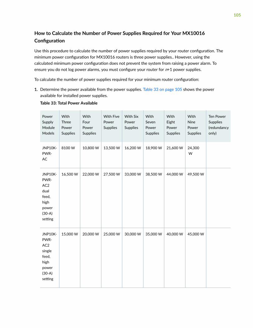
How to Calculate the Number of Power Supplies Required for Your MX10016Configuration
Use this procedure to calculate the number of power supplies required by your router configuration. Theminimum power configuration for MX10016 routers is three power supplies.. However, using thecalculated minimum power configuration does not prevent the system from raising a power alarm. Toensure you do not log power alarms, you must configure your router for n+1 power supplies.
To calculate the number of power supplies required for your minimum router configuration:
1. Determine the power available from the power supplies. Table 33 on page 105 shows the poweravailable for installed power supplies.
Table 33: Total Power Available
PowerSupplyModuleModels
WithThreePowerSupplies
WithFourPowerSupplies
With FivePowerSupplies
With SixPowerSupplies
WithSevenPowerSupplies
WithEightPowerSupplies
WithNinePowerSupplies
Ten PowerSupplies(redundancyonly)
JNP10K-PWR-AC
8100 W 10,800 W 13,500 W 16,200 W 18,900 W 21,600 W 24,300 W
JNP10K-PWR-AC2dualfeed,highpower(30-A)setting
16,500 W 22,000 W 27,500 W 33,000 W 38,500 W 44,000 W 49,500 W
JNP10K-PWR-AC2singlefeed,highpower(30-A)setting
15,000 W 20,000 W 25,000 W 30,000 W 35,000 W 40,000 W 45,000 W
105

Table 33: Total Power Available (Continued)
PowerSupplyModuleModels
WithThreePowerSupplies
WithFourPowerSupplies
With FivePowerSupplies
With SixPowerSupplies
WithSevenPowerSupplies
WithEightPowerSupplies
WithNinePowerSupplies
Ten PowerSupplies(redundancyonly)
JNP10K-PWR-DC
12,500 W 15,000 W 17,500 W 20,000 W 22,500 W
JNP10K-PWR-DC2dualfeed,highpower(80-A)setting
27,500 W 33,000 W 38,500 W 44,000 W 49,500 W
JNP10K-PWR-DC2dualfeed,lowpower(60-A)setting
22,000 W 26,400 W 30,800 W 35,200 W 39,600 W
JNP10K-PWR-DC2singlefeed,highpower(80-A)setting
13,750 W 16,500 W 19,250 W 22,000 W 24,750 W
106

Table 33: Total Power Available (Continued)
PowerSupplyModuleModels
WithThreePowerSupplies
WithFourPowerSupplies
With FivePowerSupplies
With SixPowerSupplies
WithSevenPowerSupplies
WithEightPowerSupplies
WithNinePowerSupplies
Ten PowerSupplies(redundancyonly)
JNP10K-PWR-DC2singlefeed,lowpower(60-A)setting
11,000 W 13,200 W 15,400 W 17,600 W 19,800 W
NOTE: The HVAC/HVDC power supply, JNP10K-PWR-AC2, has a set of DIP switches on thefaceplate that allows you to configure the power supply for either high power (30 A) or lowpower (20 A) input mode. If any JNP10K-PWR-AC2. power supply is set to 20 A, then thepower budget for all power supplies installed in the system becomes 20 A, regardless if otherpower supplies are set at 30 A. This design is to prevent overloading of the power supply thatis set to 20 A. See Power Input and Output Voltages for JNP10K-PWR-AC2 Power Suppliesfor details on setting the DIP switches.
2. Determine the total power required for your configuration with line cards installed. The total poweravailable to the chassis is calculated by dividing the wattage needed by the power rating, and thenrounding off the result.
In the previous examples, we calculated that an MX10016 AC power system requires 28,000 W with16 line cards. From Table 33 on page 105, we can determine that a 5500 W power supply, such asthe JNP10K-PWR-AC2 or the JNP10K-PWR-DC2, would work. In this example, we calculate thetotal power available using JNP10K-PWR-AC2 power supplies in 30 A mode with a single powerfeed:
(28000 W) / (5000 W) = 5.6
Round up the result to 6 HVAC power supplies for a non-redundant power system. Add an additionalpower supply for redundancy.
107

JNP10K-PWR-AC Power Specifications
An MX10016 router in redundant configuration can use either AC or DC power supplies; baseconfiguration routers are AC power only.
Table 34 on page 108 lists the power specifications for the AC power supply (JNP10K-PWR-AC) used inan MX10016 chassis.
Table 34: Power Specifications for a JNP10K-PWR-AC Power Supply
Item Specifications
AC input voltage Operating range: 200–240 VAC
AC input line frequency 50–60 Hz
AC input current rating 16 A
AC output power 2700 W
Table 35 on page 108 shows the physical specifications for an AC power supply.
Table 35: Physical Specifications for a JNP10K-PWR-AC Power Supply
Specification Value
Height 3.5 in. (8.89 cm)
Width 3.6 in. (9.14 cm)
Depth 14.4 in. (36.58 cm)
Weight 6.8 lb 3.08 kg)
108

JNP10K-PWR-AC2 Power Specifications
MX10008 and MX10016 redundant configuration routers can use either AC or DC power supplies; baseconfiguration routers are AC only. The JNP10K-PWR-AC2 power supply supports AC, HVAC, andHVDC.
Table 36 on page 109 lists the power specifications for the AC power supply (JNP10K-PWR-AC) used ina MX10000 chassis.
Table 36: Power Specifications for a JNP10K-PWR-AC2 Power Supply
Item Specifications
AC input voltage 180–305 VAC
DC input voltage 190–410 VDC
Input current rating 28.5 A
DC output power 12.3 V, 5500 W with dual feed and 5000 W with single feed
Table 37 on page 109 shows the physical specifications for a JNP10K-PWR-AC2 power supply.
Table 37: Physical Specifications for a JNP10K-PWR-AC2 Power Supply
Specification Value
Height 3.5 in. (8.89 cm)
Width 3.6 in. (9.14 cm)
Depth 15.1 in. (38.35 cm)
Weight 11.4 lb (5.17 kg)
109

MX10016 Power Cord Specifications
IN THIS SECTION
JNP10K-PWR-AC Power Cable Specifications | 111
JNP10K-PWR-AC2 Power Cable Specifications | 113
JNP10K-PWR-AC2 Power Cable Specifications for 30-A Input | 116
Each AC power supply has two independent 16 A rated AC inlets on the faceplate. Most sites distributepower through a main conduit that leads to frame-mounted power distribution panels, one of which canbe located at the top of the rack that houses the router. An AC power cord connects each power supplyto the power distribution panel.
Each detachable AC power cord is 8 feet (approximately 2.5 meters) long. The coupler end of theappliance cord inserts into the AC appliance inlet on the faceplate of the AC power supply. The couplertype is C19 as described by the International Electrotechnical Commission (IEC) standard 60320. Theplug end of the power cord fits into the power source outlet that is standard for your geographicallocation.
NOTE: In North America, AC power cords must not exceed 15 feet (approximately 4.5 meters) inlength, to comply with National Electrical Code (NEC) Sections 400-8 (NFPA 75, 5-2.2) and210-52 and Canadian Electrical Code (CEC) Section 4-010(3). The cords shipped with the routerto North America and Canada are in compliance.
MX10000 AC, high voltage alternating current (HVAC), and high voltage direct current (HVDC) havespecific cord requirements. Use the following sections to determine the cable requirements based on themodel of your power supply and any mode settings:
• JNP10K-PWR-AC see "JNP10K-PWR-AC Power Cable Specifications" on page 111
• JNP10K-PWR-AC2 with 20-A input, see "JNP10K-PWR-AC2 Power Cable Specifications" on page113
• JNP10K-PWR-AC2 with 30-A input, see "JNP10K-PWR-AC2 Power Cable Specifications for 30-AInput" on page 116
110

JNP10K-PWR-AC Power Cable Specifications
Table 38 on page 111 lists the AC power cord specifications for JNP10K-PWR-AC for various countriesand regions.
Table 38: AC Power Cord Specifications for JNP10K-PWR-AC Power Supplies
Country/Region ElectricalSpecifications
Plug Standards Juniper ModelNumber
Graphic
Argentina 250 VAC, 16 A,50 Hz
IRAM Type RA/3/20
CBL-EX-PWR-C19-AR
Australia 250 VAC, 15 A,50 Hz
AS/NZS 3112 TypeSAA/3/15
CBL-EX-PWR-C19-AU
Brazil 250 VAC, 16 A,50 Hz
NBR 14136: 2002Type BR/3/20
CBL-EX-PWR-C19-BR
China 250 VAC, 16 A,50 Hz
GB 1002 Type PRC/3/16
CBL-EX-PWR-C19-CH
Europe (except Italy,Switzerland, andUnited Kingdom)
250 VAC, 16 A,50 Hz
CEE (7) VII TypeVIIG
CBL-EX-PWR-C19-EU
India 250 AC, 16 A,50 Hz
SABS 164/1:1992Type ZA/3
CBL-EX-PWR-C19-SA
111

Table 38: AC Power Cord Specifications for JNP10K-PWR-AC Power Supplies (Continued)
Country/Region ElectricalSpecifications
Plug Standards Juniper ModelNumber
Graphic
Israel 250 AC, 16 A,50 Hz
SI 32/1971 TypeIL/3
CBL-EX-PWR-C19-IL
Italy 250 VAC, 16 A,50 Hz
CEI 23-16 Type I/3/16
CBL-EX-PWR-C19-IT
Japan 250 VAC, 16 A,60 Hz
NEMA 6–20 TypeN6/20
CBL-EX-PWR-C19-JP (default)
250 VAC, 16 A,50 Hz or 60 Hz
NEMA 6–20 TypeN6/20, locking
CBL-EX-PWR-C19-JPL
Korea 250 VAC, 16 A,50 Hz
CEE (7) VII TypeVIIG
CBL-EX-PWR-C19-KR
North America 250 VAC, 16 A,60 Hz
NEMA 6–20 TypeN6/20
CBL-EX-PWR-C19-US (default)
250 VAC, 16 A,50 Hz or 60 Hz
NEMA 6–20 TypeN6/20, locking
CBL-EX-PWR-C19-USL
112

Table 38: AC Power Cord Specifications for JNP10K-PWR-AC Power Supplies (Continued)
Country/Region ElectricalSpecifications
Plug Standards Juniper ModelNumber
Graphic
South Africa 250 VAC, 16 A,50 Hz
SABS 164/1:1992Type ZA/3
CBL-EX-PWR-C19-SA
Switzerland 250 VAC, 16 A,50 Hz
SEV 5934/2 Type23G
CBL-EX-PWR-C19-SZ
United Kingdom 250 VAC, 13 A,50 Hz
BS 1363/A TypeBS89/13
CBL-EX-PWR-C19-UK
Worldwide (exceptJapan)
250 VAC, 16 A,50 Hz
EN 60320-2-2/1 CBL-EX-PWR-C19-C20
JNP10K-PWR-AC2 Power Cable Specifications
The JNP10K-PWR-AC2 power supply operates in two modes:
• 30-A input with 5500 W output
"JNP10K-PWR-AC2 Power Cable Specifications for 30-A Input" on page 116 shows cables andconnectors for 30-A input.
• 20-A input with 3000 W output
Table 39 on page 114 shows cables appropriate for 20-A input.
113
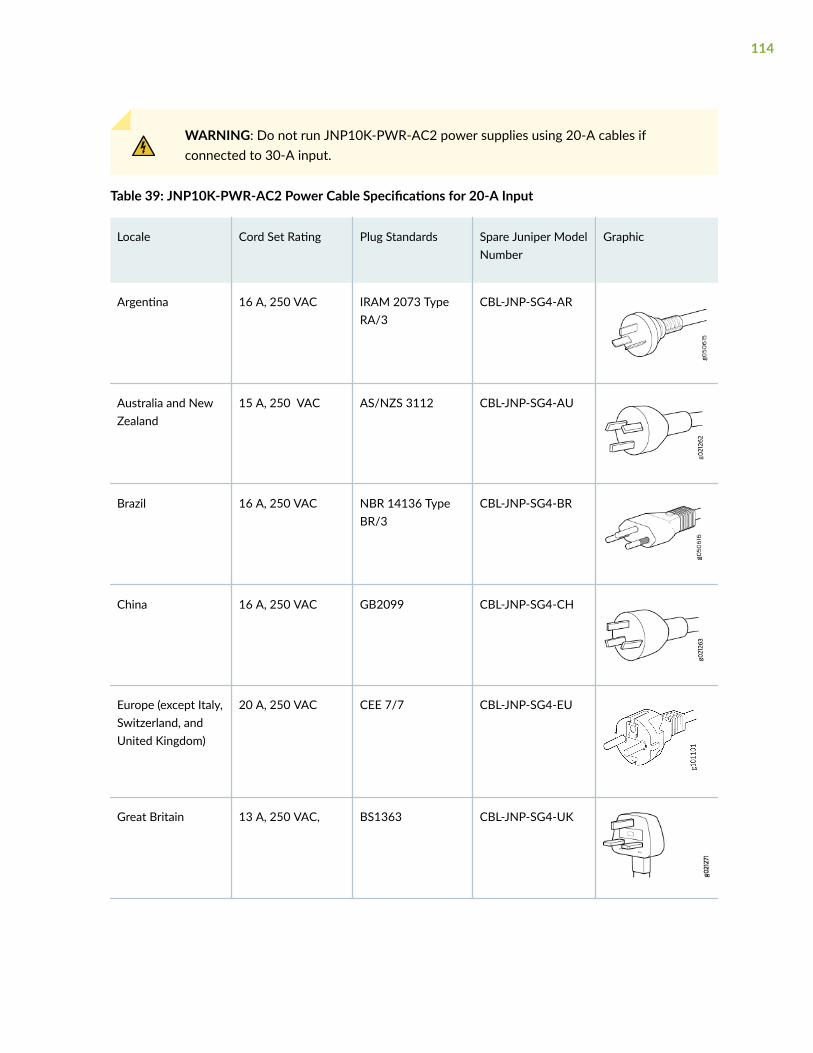
WARNING: Do not run JNP10K-PWR-AC2 power supplies using 20-A cables ifconnected to 30-A input.
Table 39: JNP10K-PWR-AC2 Power Cable Specifications for 20-A Input
Locale Cord Set Rating Plug Standards Spare Juniper ModelNumber
Graphic
Argentina 16 A, 250 VAC IRAM 2073 TypeRA/3
CBL-JNP-SG4-AR
Australia and NewZealand
15 A, 250 VAC AS/NZS 3112 CBL-JNP-SG4-AU
Brazil 16 A, 250 VAC NBR 14136 TypeBR/3
CBL-JNP-SG4-BR
China 16 A, 250 VAC GB2099 CBL-JNP-SG4-CH
Europe (except Italy,Switzerland, andUnited Kingdom)
20 A, 250 VAC CEE 7/7 CBL-JNP-SG4-EU
Great Britain 13 A, 250 VAC, BS1363 CBL-JNP-SG4-UK
114
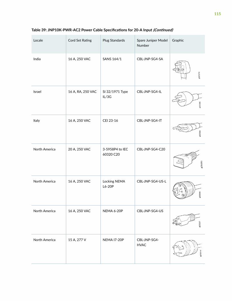
Table 39: JNP10K-PWR-AC2 Power Cable Specifications for 20-A Input (Continued)
Locale Cord Set Rating Plug Standards Spare Juniper ModelNumber
Graphic
India 16 A, 250 VAC SANS 164/1 CBL-JNP-SG4-SA
Israel 16 A, RA, 250 VAC SI 32/1971 TypeIL/3G
CBL-JNP-SG4-IL
Italy 16 A, 250 VAC CEI 23-16 CBL-JNP-SG4-IT
North America 20 A, 250 VAC 3-5958P4 to IEC60320 C20
CBL-JNP-SG4-C20
North America 16 A, 250 VAC Locking NEMAL6-20P
CBL-JNP-SG4-US-L
North America 16 A, 250 VAC NEMA 6-20P CBL-JNP-SG4-US
North America 15 A, 277 V NEMA I7-20P CBL-JNP-SG4-HVAC
115

Table 39: JNP10K-PWR-AC2 Power Cable Specifications for 20-A Input (Continued)
Locale Cord Set Rating Plug Standards Spare Juniper ModelNumber
Graphic
North America 20 A, 250 V IEC 320P6W CG_CBL-APP-400-02
South Africa 16 A, 250 VAC SANS 164/1 CBL-JNP-SG4-SA
Switzerland 16 A, 250 VAC CEI 23-50 CBL-JNP-SG4-SZ
JNP10K-PWR-AC2 Power Cable Specifications for 30-A Input
The JNP10K-PWR-AC2 HVAC or HVDC power supplies requires a high current cable assembly whenset for 30-A input. One end of the cable has an Anderson APP-400 connector, the other end of thecable is bare wire. See Figure 46 on page 117 and Table 40 on page 117. These cables are separatelyorderable and are not shipped automatically with JNP10K-PWR-AC2 orders. An example of the right-angle cable and connector is shown in Figure 48 on page 118.
116
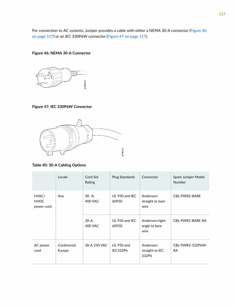
For connection to AC systems, Juniper provides a cable with either a NEMA 30-A connector (Figure 46on page 117) or an IEC 330P6W connector (Figure 47 on page 117).
Figure 46: NEMA 30-A Connector
Figure 47: IEC 330P6W Connector
Table 40: 30-A Cabling Options
Locale Cord SetRating
Plug Standards Connector Spare Juniper ModelNumber
HVAC/HVDCpower cord
Any 30- A,400 VAC
UL 950 and IEC60950
Anderson/straight to barewire
CBL-PWR2-BARE
30-A,400 VAC
UL 950 and IEC60950
Anderson/right-angle to barewire
CBL-PWR2-BARE-RA
AC powercord
ContinentalEurope
30-A 250 VAC UL 950 andIEC332P6
Anderson/straight to IEC332P6
CBL-PWR2-332P6W-RA
117
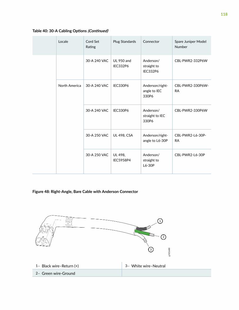
Table 40: 30-A Cabling Options (Continued)
Locale Cord SetRating
Plug Standards Connector Spare Juniper ModelNumber
30-A 240 VAC UL 950 andIEC332P6
Anderson/straight toIEC332P6
CBL-PWR2-332P6W
North America 30-A 240 VAC IEC330P6 Anderson/right-angle to IEC330P6
CBL-PWR2-330P6W-RA
30-A 240 VAC IEC330P6 Anderson/straight to IEC330P6
CBL-PWR2-330P6W
30-A 250 VAC UL 498, CSA Anderson/right-angle to L6-30P
CBL-PWR2-L6-30P-RA
30-A 250 VAC UL 498,IEC5958P4
Anderson/straight toL6-30P
CBL-PWR2-L6-30P
Figure 48: Right-Angle, Bare Cable with Anderson Connector
1— Black wire–Return (+) 3— White wire–Neutral
2— Green wire-Ground
118

JNP10K-PWR-DC Power Specifications
The DC power supply (JNP10K-PWR-DC) is supported only in the MX10016 redundant configuration.Table 41 on page 119 lists the power specifications for the DC power supply used in an MX10016chassis.
Table 41: Power Specifications for the JNP10K-PWR-DC Power Supply
Item Specifications
DC input voltage • Minimum operating voltage: –40 VDC
• Nominal operating voltage: –48 VDC
• Operating voltage range: –40 VDC through –72 VDC
DC input current rating 60 A maximum at nominal operating voltage (–48 VDC) for eachinput terminal
Output power 2500 W
Table 42 on page 119 shows the physical specifications for a DC power supply used in an MX10016router.
Table 42: Physical Specifications of the JNP10K-PWR-DC Power Supply
Specification Value
Height 3.5 in. (8.89 cm)
Width 3.6 in. (9.14 cm)
Depth 14.4 in. (36.58 cm)
Weight 6 lb (2.72 kg)
119

JNP10K-PWR-DC2 Power Specifications
HVDC power supplies (JNP10K-PWR-DC2) are supported in only the MX10008 and MX10016redundant configuration. Table 43 on page 120 lists the power specifications for the HVDC powersupply used in an MX10000 chassis.
Table 43: Power Specifications for the JNP10K-PWR-DC2 Power Supply
Item Specifications
DC input voltage • Minimum operating voltage: –40 VDC
• Nominal operating voltage: –48 VDC
• Operating voltage range: –40 VDC through –72 VDC
DC input current rating • 76-A maximum at minimum operating voltage (-40 VDC) with80-A dip switch setting and 5500-W output load.
• 64-A maximum at nominal operating voltage (–48 VDC) with80-A dip switch setting and 5500-W output load.
• 60-A maximum at minimum operating voltage (-40 VDC) with60-A dip switch setting and 4400-W output load.
• 50-A maximum at nominal operating voltage (-48 VDC) with60-A dip switch setting and 4400-W output load.
Output power 2200 W for low input (60-A) single feed
4400 W for low input (60-A) dual feed
2750 W for high input (80-A) single feed
5500 W for high input (80-A) dual feed
Table 44 on page 121 shows the physical specifications for a JNP10K-PWR-DC2 power supply.
120

Table 44: Physical Specifications of a JNP10K-PWR-DC2 Power Supply
Specification Value
Height 3.5 in. (8.89 cm)
Width 3.6 in. (9.14 cm)
Depth 16.05 in. (40.77 cm)
Weight 8.1 lb (3.67 kg)
MX10016 Grounding Cable and Lug Specifications
You must install the router in a restricted-access location and ensure it is adequately grounded at alltimes. Proper grounding ensures your router is operating correctly and that it meets safety andelectromagnetic interference (EMI) requirements. The MX10016 modular chassis has a 2-hole protectivegrounding terminal on the rear of the chassis beneath the power supplies for grounding.
For AC powered systems, you must also use the grounding wire in the AC power cord along with the 2-hole lug ground connection. This tested system meets or exceeds all applicable EMC regulatoryrequirements with the 2-hole protective grounding terminal.
WARNING: To comply with GR-1089 requirements, all intra-building copper cablingused for SFP+, QSFP+, and QSFP28 ports must be shielded and grounded at both ends.
CAUTION: Before you start installing the router, endure that a licensed electricianattaches a cable lug to the grounding cables. See "Connect an MX10016 to EarthGround" on page 159. A cable with an incorrectly attached lug can damage the router.
Before connecting the router to earth ground, review the following information:
• Two threaded inserts (PEM nuts) are provided on the lower rear of the chassis for connecting therouter to earth ground. The grounding points are spaced at 0.63 in. (16 mm).
• The grounding lug required is a Panduit LCD6-10A-L or equivalent (provided). The grounding lugaccommodates 6 AWG (13.3 mm²) stranded wire. If one or more JNP10K-PWR-DC2 power supplies
121

are installed in the chassis and set for high input (80-A), use the Panduit LCD4-14A-L or equivalent(provided). This lug accommodates 4 AWG (21.1mm²) stranded wire.
• The grounding cable that you provide for an MX10016 must be the same size or heavier than theinput wire of each power supply. Minimum recommendations are 6 AWG (13.3 mm²) strandedcopper wire, Class B; 90° C wire, or as permitted by local code.
RELATED DOCUMENTATION
MX10016 Power System | 50
MX10016 Transceiver and Cable Specifications
IN THIS SECTION
Optical Transceiver and Cable Support | 122
Cable Specifications for Console and Management Connections | 123
Understanding Fiber-Optic Cable Signal Loss, Attenuation, and Dispersion | 124
Calculating the Fiber-Optic Cable Power Budget for an MX10016 | 126
Calculating the Fiber-Optic Cable Power Margin for an MX10016 | 126
Optical Transceiver and Cable Support
The MX10016 router has 16 slots for the line cards that can support a maximum of 2304 ports as 10-Gigabit Ethernet ports, 576 ports as 40-Gigabit Ethernet ports, or 480 ports as 100-Gigabit Ethernetports. Each of the network ports on the port panel supports quad small form-factor pluggable plus(QSFP+) transceivers and QSFP28 transceivers.
You can find information about the pluggable transceivers supported on your Juniper Networks deviceby using the Hardware Compatibility Tool. In addition to transceiver and connector type, the optical andcable characteristics—where applicable—are documented for each transceiver. The HardwareCompatibility Tool enables you to search by product, displaying all the transceivers supported on thatdevice, or category, by interface speed or type. The list of supported transceivers for the MX10016 islocated at https://pathfinder.juniper.net/hct/product/#prd=MX10016.
122
CAUTION: The Juniper Networks Technical Assistance Center (JTAC) providescomplete support for Juniper-supplied optical modules and cables. However, JTAC doesnot provide support for third-party optical modules and cables that are not qualified orsupplied by Juniper Networks. If you face a problem running a Juniper device that usesthird-party optical modules or cables, JTAC may help you diagnose host-related issues ifthe observed issue is not, in the opinion of JTAC, related to the use of the third-partyoptical modules or cables. Your JTAC engineer will likely request that you check thethird-party optical module or cable and, if required, replace it with an equivalentJuniper-qualified component.
Use of third-party optical modules with high-power consumption (for example,coherent ZR or ZR+) can potentially cause thermal damage to or reduce the lifespan ofthe host equipment. Any damage to the host equipment due to the use of third-partyoptical modules or cables is the users’ responsibility. Juniper Networks will accept noliability for any damage caused due to such use.
SEE ALSO
Supported Transceivers
Cable Specifications for Console and Management Connections
Table 45 on page 124 lists the specifications for the cables that connect the MX10016 router to amanagement device.
NOTE: The MX10016 router can be configured with SFP management ports that support1000BASE-SX transceivers.
123

Table 45: Cable Specifications for Console and Management Connections for an MX10016
Port on MX10016router
Cable Specification Cable Supplied Maximum Length DeviceReceptacle
Console port RS-232 (EIA-232) serialcable
One 7-feet (2.13-meter)long RJ-45 patch cableand RJ-45 to DB-9adapter
7 feet(2.13 meters)
RJ-45
Management port Category 5 cable orequivalent suitable for1000BASE-T operation
One 7-feet (2.13-meter)long RJ-45 patch cable
328 feet(100 meters)
RJ-45
Understanding Fiber-Optic Cable Signal Loss, Attenuation, andDispersion
IN THIS SECTION
Signal Loss in Multimode and Single-Mode Fiber-Optic Cables | 124
Attenuation and Dispersion in Fiber-Optic Cable | 125
To determine the power budget and power margin needed for fiber-optic connections, you need tounderstand how signal loss, attenuation, and dispersion affect transmission. The MX10016 router usesvarious types of network cables, including multimode and single-mode fiber-optic cables.
Signal Loss in Multimode and Single-Mode Fiber-Optic Cables
Multimode fiber is large enough in diameter to allow rays of light to reflect internally (bounce off thewalls of the fiber). Interfaces with multimode optics typically use LEDs as light sources. However, LEDsare not coherent light sources. They spray varying wavelengths of light into the multimode fiber, whichreflects the light at different angles. Light rays travel in jagged lines through a multimode fiber, causingsignal dispersion. When light traveling in the fiber core radiates into the fiber cladding (layers of lowerrefractive index material in close contact with a core material of higher refractive index), higher-order
124
mode loss occurs. Together, these factors reduce the transmission distance of multimode fiber comparedto that of single-mode fiber.
Single-mode fiber is so small in diameter that rays of light reflect internally through one layer only.Interfaces with single-mode optics use lasers as light sources. Lasers generate a single wavelength oflight, which travels in a straight line through the single-mode fiber. Compared to multimode fiber, single-mode fiber has a higher bandwidth and can carry signals for longer distances. It is consequently moreexpensive.
Attenuation and Dispersion in Fiber-Optic Cable
An optical data link functions correctly provided that modulated light reaching the receiver has enoughpower to be demodulated correctly. Attenuation is the reduction in strength of the light signal duringtransmission. Passive media components such as cables, cable splices, and connectors causeattenuation. Although attenuation is significantly lower for optical fiber than for other media, it stilloccurs in both multimode and single-mode transmission. An efficient optical data link must transmitenough light to overcome attenuation.
Dispersion is the spreading of the signal over time. The following two types of dispersion can affectsignal transmission through an optical data link:
• Chromatic dispersion, which is the spreading of the signal over time caused by the different speedsof light rays.
• Modal dispersion, which is the spreading of the signal over time caused by the different propagationmodes in the fiber.
For multimode transmission, modal dispersion, rather than chromatic dispersion or attenuation, usuallylimits the maximum bit rate and link length. For single-mode transmission, modal dispersion is not afactor. However, at higher bit rates and over longer distances, chromatic dispersion limits the maximumlink length.
An efficient optical data link must have enough light to exceed the minimum power that the receiverrequires to operate within its specifications. In addition, the total dispersion must be within the limitsspecified for the type of link in the Telcordia Technologies document GR-253-CORE (Section 4.3) andInternational Telecommunications Union (ITU) document G.957.
When chromatic dispersion is at the maximum allowed, its effect can be considered as a power penaltyin the power budget. The optical power budget must allow for the sum of component attenuation,power penalties (including those from dispersion), and a safety margin for unexpected losses.
125

Calculating the Fiber-Optic Cable Power Budget for an MX10016
Calculate the link's power budget when planning fiber-optic cable layout and distances to ensure thatfiber-optic connections have sufficient power for correct operation. The power budget is the maximumamount of power the link can transmit. When you calculate the power budget, you use a worst-caseanalysis to provide a margin of error, even though all the parts of an actual system do not operate at theworst-case levels.
To calculate the worst-case estimate for the fiber-optic cable power budget (PB) for the link:
1. Determine values for the link's minimum transmitter power (PT) and minimum receiver sensitivity(PR). For example, here, (PT) and (PR) are measured in decibels, and decibels are referenced to 1milliwatt (dBm):
PT = –15 dBm
PR = –28 dBm
NOTE: See the specifications for your transmitter and receiver to find the minimumtransmitter power and minimum receiver sensitivity.
2. Calculate the power budget (PB) by subtracting (PR) from (PT):
–15 dBm – (–28 dBm) = 13 dBm
Calculating the Fiber-Optic Cable Power Margin for an MX10016
Before calculate the power margin, see "Calculating the Fiber-Optic Cable Power Budget for anMX10016 " on page 126.
Calculate the link's power margin when planning fiber-optic cable layout and distances to ensure thatfiber-optic connections have sufficient signal power to overcome system losses and still satisfy theminimum input requirements of the receiver for the required performance level. The power margin (PM )is the amount of power available after attenuation or link loss (LL) has been subtracted from the powerbudget (PB).
When you calculate the power margin, you use a worst-case analysis to provide a margin of error, eventhough all the parts of an actual system do not operate at worst-case levels. A power margin (PM )greater than zero indicates that the power budget is sufficient to operate the receiver and that it doesnot exceed the maximum receiver input power. This means the link will work. A (PM) that is zero ornegative indicates insufficient power to operate the receiver. See the specification for your receiver tofind the maximum receiver input power.
126

To calculate the worst-case estimate for the power margin (PM) for the link:
1. Determine the maximum value for link loss (LL) by adding estimated values for applicable link-lossfactors; for example, use the sample values for various factors as provided in Table 46 on page 127(here, the link is 2 km long and multimode, and the (PB) is 13 dBm).
Table 46: Estimated Values for Factors Causing Link Loss (LL)
Link-Loss Factor Estimated Link Loss Value Sample Link Loss (LL) Calculation Values
Higher-order modelosses
Multimode—0.5 dBm 0.5 dBm
Single-mode—None 0 dBm
Modal and chromaticdispersion
Multimode—None, if product ofbandwidth and distance is lessthan 500 MHz/km
0 dBm
Single-mode—None 0 dBm
Connector 0.5 dBm This example assumes five connectors. Loss forfive connectors: 5 (0.5 dBm) = 2.5 dBm.
Splice 0.5 dBm This example assumes two splices. Loss for twosplices: 2 (0.5 dBm) = 1 dBm.
Fiber attenuation Multimode—1 dBm/km This example assumes the link is 2 km long.Fiber attenuation for 2 km: 2 km (1 dBm/km) = 2 dBm.
Single-mode—0.5 dBm/km This example assumes the link is 2 km long.Fiber attenuation for 2 km: 2 km (0.5 dBm/km) = 1 dBm.
Clock Recovery Module(CRM)
1 dBm 1 dBm
127

NOTE: For information about the actual amount of signal loss caused by equipment and otherfactors, see your vendor documentation for that equipment.
2. Calculate the (PM) by subtracting (LL) from (PB):
PB– LL = PM
13 dBm – 0.5 dBm [HOL] – 5 (0.5 dBm) – 2 (0.5 dBm) – 2 km (1.0 dBm/km) – 1 dB [CRM] = PM
13 dBm – 0.5 dBm – 2.5 dBm – 1 dBm – 2 dBm – 1 dBm = PM
PM = 6 dBm
The calculated power margin is greater than zero, indicating that the link has sufficient power fortransmission. Also, the power margin value does not exceed the maximum receiver input power.Refer to the specifications for your receiver to find the maximum receiver input power.
MX10016 Alarm and Management CableSpecifications and Pinouts
IN THIS SECTION
Console Port Connector Pinouts for an MX10016 Router | 128
USB Port Specifications for an MX10016 | 130
Management Port Connector Pinouts for an MX10016 | 130
Console Port Connector Pinouts for an MX10016 Router
The console port (labeled CON) on the RCB panel is an RS-232 serial interface that uses an RJ-45connector to connect to a console management device. The default baud rate for the console port is9600 baud.
Table 47 on page 129 provides the pinout information for the RJ-45 console connector. An RJ-45 cableand RJ-45 to DB-9 adapter are supplied with the MX10016.
128

NOTE: If your laptop or PC does not have a DB-9 plug connector pin and you want to connectyour laptop or PC directly to an MX10016 router, use a combination of the RJ-45 cable andRJ-45 to DB-9 adapter supplied with the device and a USB to DB-9 plug adapter. You mustprovide the USB to DB-9 plug adapter.
Table 47: Console Port Connector Pinouts for an MX10016
Pin Signal Description
1 RTS output Request to send
2 DTR output
TOD output for PTP applications
Data terminal ready
Time of day for Precision TimeProtocol (PTP). You can use DTR pinsas a TOD universal asynchronousreceiver/transmitter (UART) by usingbreakout cables.
3 TxD output Transmit data
4 Signal oround Signal ground
5 Signal oround Signal ground
6 RxD input Receive data
7 DCD input
TOD iutput for PTP applications
Data carrier detect
Time of day for PTP. You can use DCDpins as a TOD UART by using breakoutcables.
8 CTS input Clear to send
129
USB Port Specifications for an MX10016
The following Juniper Networks USB flash drives have been tested and are officially supported for theUSB port in the MX10016 router:
• RE-USB-1G-S—1-gigabyte (GB) USB flash drive
• RE-USB-2G-S—2-GB USB flash drive
• RE-USB-4G-S—4-GB USB flash drive
CAUTION: Any USB memory product not listed as supported for the MX10016 routerhas not been tested by Juniper Networks. The use of any unsupported USB memoryproduct could expose your device to unpredictable behavior. Juniper NetworksTechnical Assistance Center (JTAC) can provide only limited support for issues related tounsupported hardware. We strongly recommend that you use only supported USB flashdrives.
CAUTION: Remove the USB flash drive before upgrading Junos OS or rebooting anMX10016 router. Failure to do so could expose your device to unpredictable behavior.
NOTE: USB flash drives used with the MX10016 router must support USB 2.0 or later.
Management Port Connector Pinouts for an MX10016
The 1000BASE-T RJ-45 management ports use an RJ-45 connector to connect either to the controlplane and management network in an MX10016 router, or to a management device for out-of-bandmanagement.
Table 48 on page 131 provides the pinout information of the RJ-45 management port connector. AnRJ-45 cable is supplied with the MX10016 router.
130
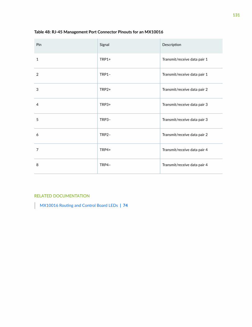
Table 48: RJ-45 Management Port Connector Pinouts for an MX10016
Pin Signal Description
1 TRP1+ Transmit/receive data pair 1
2 TRP1– Transmit/receive data pair 1
3 TRP2+ Transmit/receive data pair 2
4 TRP3+ Transmit/receive data pair 3
5 TRP3– Transmit/receive data pair 3
6 TRP2– Transmit/receive data pair 2
7 TRP4+ Transmit/receive data pair 4
8 TRP4– Transmit/receive data pair 4
RELATED DOCUMENTATION
MX10016 Routing and Control Board LEDs | 74
131

3CHAPTER
Initial Installation and Configuration
MX10016 Installation Overview | 133
Unpacking an MX10016 Router and Components | 134
Installing the Mounting Hardware | 144
Installing an MX10016 into a Four-Post Rack | 146
Installing the Front Door on an MX10016 | 150
Connecting an MX10016 to Power | 159
Connecting an MX10016 to External Devices | 163
Configuring an MX10016 Router | 165

MX10016 Installation Overview
The MX10016 is a rigid sheet-metal router that houses the other hardware components such as Routingand Control Boards (RCBs), Switch Fabric Boards (SFBs), power supplies, fan trays, and line cards. Therouter is shipped in a cardboard box that has a two-layer wooden pallet base. The chassis is bolted tothe pallet base. You can install an MX10016 router in a standard 19 in. (483 mm) equipment rack byusing the supplied rack mount kit and the flanges attached to the chassis.
To install the MX10016:
1. Unpack the router following the instructions in "Unpacking an MX10016 Router and Components"on page 134.
2. Mount the chassis in the rack following the instructions in "Installing an MX10016 into a Four-PostRack" on page 146.
WARNING: Because of the weight of the chassis, manual mounting is notrecommended.
3. Install the line cards following the instructions in "Install an MPC in an MX10016" on page 243.
4. Connect the chassis to earth ground by following the instructions in "Connect an MX10016 to EarthGround" on page 159.
5. Connect power to the power supplies by following the instructions in "Connecting an MX10016 toPower" on page 159.
6. Connect to the network.
• To connect the router to a network for out-of-band management, follow the instructions in"Connecting an MX10016 to a Network for Out-of-Band Management" on page 163.
• To connect the router to a management console, follow the instructions in "Connecting anMX10016 Router to a Management Console" on page 164.
7. Configure the router by following the instructions in "Configuring an MX10016 Router" on page 165.
8. Install optional equipment such as the cable management system. See "Install the Cable ManagementSystem" on page 250.
RELATED DOCUMENTATION
MX10016 Rack Requirements | 96
Depth Clearance Requirements for Airflow and Hardware Maintenance for an MX10016 | 98
MX10016 Chassis Lifting Guidelines | 302
133

Unpacking an MX10016 Router and Components
IN THIS SECTION
Unpacking an MX10016 | 134
Unpacking Line Cards, Routing and Control Boards, and Switch Fabric Boards | 137
Comparing the MX10016 Order to the Packing List | 138
Register Products—Mandatory to Validate SLAs | 143
Unpacking an MX10016
After you prepare the installation site as described in " Site Preparation Checklist" on page 91, you canunpack the router.
NOTE: The chassis is maximally protected inside the shipping box. Do not unpack it until you areready to begin the installation.
Ensure that you have the following parts and tools available to unpack the MX10016:
• A 13/32 in. (10 mm) open-end wrench or socket wrench to remove the bracket bolts from theshipping pallet
• A box cutter or a packing knife to slice open the nylon straps and tape that seal the crate and boxes
The chassis ships in a cardboard box that has a two-layer wooden pallet base with foam cushioningbetween the layers. The router chassis is bolted to the pallet base.
The shipper has the option to ship either the front door separately or to ship the front door along withthe chassis. If the front door arrives with the chassis, set aside the front door box until you are ready toverify the contents of the order.
134
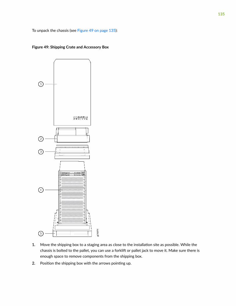
To unpack the chassis (see Figure 49 on page 135):
Figure 49: Shipping Crate and Accessory Box
1. Move the shipping box to a staging area as close to the installation site as possible. While thechassis is bolted to the pallet, you can use a forklift or pallet jack to move it. Make sure there isenough space to remove components from the shipping box.
2. Position the shipping box with the arrows pointing up.
135
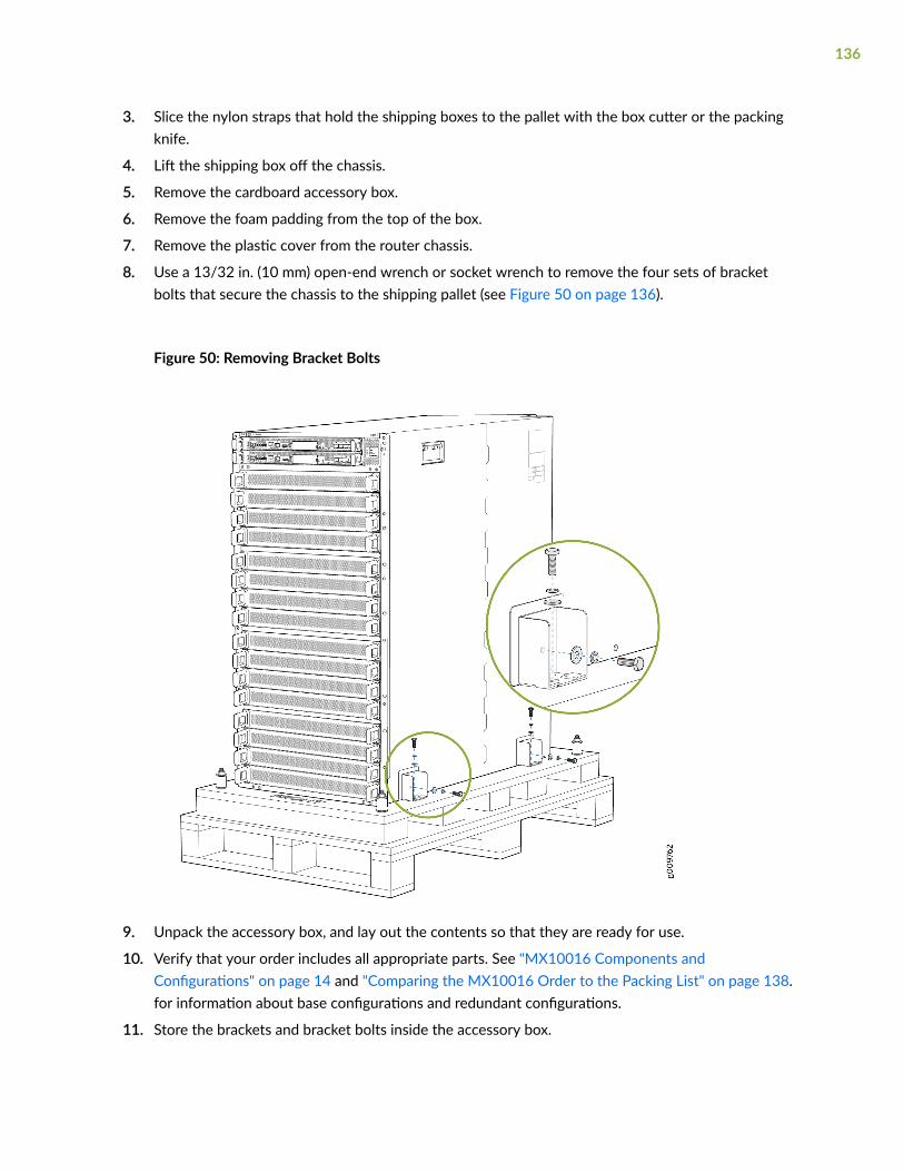
3. Slice the nylon straps that hold the shipping boxes to the pallet with the box cutter or the packingknife.
4. Lift the shipping box off the chassis.
5. Remove the cardboard accessory box.
6. Remove the foam padding from the top of the box.
7. Remove the plastic cover from the router chassis.
8. Use a 13/32 in. (10 mm) open-end wrench or socket wrench to remove the four sets of bracketbolts that secure the chassis to the shipping pallet (see Figure 50 on page 136).
Figure 50: Removing Bracket Bolts
9. Unpack the accessory box, and lay out the contents so that they are ready for use.
10. Verify that your order includes all appropriate parts. See "MX10016 Components andConfigurations" on page 14 and "Comparing the MX10016 Order to the Packing List" on page 138.for information about base configurations and redundant configurations.
11. Store the brackets and bracket bolts inside the accessory box.
136
12. Save the shipping box and packing materials in case you need to move or ship the router later.
Unpacking Line Cards, Routing and Control Boards, and Switch FabricBoards
Before you unpack a component:
• Ensure that you have taken the necessary precautions to prevent electrostatic discharge (ESD)damage. See "Prevention of Electrostatic Discharge Damage" on page 321.
• Ensure that you know how to handle and store the component. See:
• "How to Handle and Store an MX10016 MPC" on page 241
• "How to Handle and Store an MX10016 Routing and Control Board" on page 172
• "How to Handle and Store an MX10016 Switch Fabric Board" on page 229
Line cards, additional Routing and Control Boards (RCBs), and Switch Fabric Boards (SFBs) componentsare field-replaceable units (FRUs) that are shipped separately from the router chassis. The RCBs and linecards are housed in rigid sheet-metal structures. SFBs have an exposed printed circuit board on one sideand sheet metal on the other. All these components are shipped in a cardboard carton, secured withpacking material.
CAUTION: The components are maximally protected inside the shipping carton. Do notunpack them until you are ready to install the components in the router chassis.
To unpack an RCB, SFB, or line card, see Figure 51 on page 138:
1. Move the shipping carton to a staging area as close to the installation site as possible.
2. Position the carton with the arrows pointing up.
3. Open the top flaps on the shipping carton.
4. Pull out the packing material that holds the component in place.
5. Remove the component from the electrostatic bag.
137

6. Save the shipping carton and packing materials in case you need to move or ship the RCB, SFB, orline card later.
Figure 51: Unpacking a Line Card
1— Foam packing material 2— Paper packaging and electrostatic bag
Comparing the MX10016 Order to the Packing List
Use the following procedure to compare the sales order and packing list against the contents of thechassis shipping crate.
The router chassis shipment includes a packing list. Check the parts you receive in the shipping crateagainst the items on the packing list. The packing list specifies the part number and description of eachpart in your order.
If any part on the packing list is missing, contact your customer service representative, or contactJuniper Networks Customer Care from within the U.S. or Canada by telephone at 1-888-314-5822. Forinternational-dial or direct-dial options in countries without toll-free numbers, see https://www.juniper.net/support/requesting-support.html.
The following items are shipped separately from the chassis.
• Line cards
• Chassis front door kit
NOTE: The chassis front door kit is a spare part and can be shipped along with the chassis orseparately.
138

• Cable management kit
To compare the sales the contents of the chassis shipping crate with the sales order and packing list:
1. Determine the configuration. The parts shipped depend on the configuration you order.
2. Compare premium redundant configuration orders using Table 49 on page 139.
Table 49: Parts Included in the Premium Redundant Configuration Order
Component MX10016 Quantity
Chassis, including power bus 1
Routing and Control Boards (RCBs) 2
Fan tray controllers 2
Fan trays 2
AC or DC power supplies
• JNP10K-PWR-AC
• JNP10K-PWR-AC2, only available on chassis with the enhanced power bus
• JNP10K-PWR-DC
• JNP10K-PWR-DC2, only available on chassis with the enhanced power bus
10
Switch Fabric Boards (SFBs) 6
Covers in the line card slots 16
Accessory kit (see Table 51 on page 141) 1
Rack mount kit (see Table 52 on page 142) 1
Front door kit (see Table 53 on page 143) 1
139
Table 49: Parts Included in the Premium Redundant Configuration Order (Continued)
Component MX10016 Quantity
Documentation roadmap card 1
Compare base configuration orders using Table 50 on page 140.
Table 50: Parts Included in a Base Configuration Order
Component MX10016 Quantity
Chassis, including power bus 1
Routing and Control Boards (RCBs) 1
Cover in the RCB slot 1
Fan tray controllers 2
Fan trays 2
AC or DC Power supplies 5
Switch Fabric Boards (SFBs) 5
Cover in the SFB slot 1
Cover in the power supply slots 5
Cover in the line card slots 16
Accessory kit (see Table 51 on page 141) 1
Rack mount kit (see Table 52 on page 142) 1
140
Table 50: Parts Included in a Base Configuration Order (Continued)
Component MX10016 Quantity
Front door kit, lockable (see Table 53 on page 143) 1
Documentation roadmap card 1
3. Compare the contents of the accessory kit with Table 51 on page 141
Table 51: MX10016 Accessory Kit
Component Quantity
AC Configurations DC Configurations
Warranty card 1 1
End-user license agreement(EULA)
1 1
RJ-45 Ethernet cable 1 1
RJ-45 to DB9 rollover cable 1 1
Electrostatic discharge (ESD)wrist strap with cable
1 1
Media kit (flash drives, PCMCIAcard adapter)
1 1
Chassis ground lug, 2-hole,10-32, 6 AWG
1 1
141

Table 51: MX10016 Accessory Kit (Continued)
Component Quantity
AC Configurations DC Configurations
Power cord retainer clips Premium -20
Base -10
–
DC terminal lugs, 2-hole, 10-32,4 AWG
– Premium - 40
Base - 20
ESD bags 2
4. Compare the contents of the rack-mounting kit with Table 52 on page 142.
Table 52: MX10016 Rack-Mounting Kit
Component Quantity
Phillips flat-head screws, 8-32 x .375 in. 12
Rear brackets 2
Right base bracket 1
Left base bracket 1
5. Compare the contents of the front door kit with Table 53 on page 143.
142

Table 53: MX10016 Front Door Kit
Component Quantity
Front door 1
Left base bracket 1
Right base bracket 1
Latch brackets 2
Phillips flat-head screws 8
Documentation roadmap card 1
SEE ALSO
MX10016 Components and Configurations | 14
Register Products—Mandatory to Validate SLAs
Register all new Juniper Networks hardware products and changes to an existing installed product usingthe Juniper Networks website to activate your hardware replacement service-level agreements (SLAs).
CAUTION: Register product serial numbers on the Juniper Networks website andupdate the installation base data if there is any addition or change to the installationbase or if the installation base is moved. Juniper Networks will not be held accountablefor not meeting the hardware replacement service-level agreement for products that donot have registered serial numbers or accurate installation base data.
Register your product(s) at https://tools.juniper.net/svcreg/SRegSerialNum.jsp.Update your installation base at https://www.juniper.net/customers/csc/management/updateinstallbase.jsp.
143

Installing the Mounting Hardware
Ensure that you have the following parts and tools available to install the mounting hardware:
• A Phillips (+) screwdriver, number 1, 2, or 3, depending on the size of your rack screws
• A Phillips (+) screwdriver, number 2, to install the screws that connect the rear and base brackets
• 12 Phillips flat-head screws (provided)
• 14 rack screws appropriate for your rack to attach the mounting hardware to the rack (not provided)
An MX10016 router can be installed in a four-post rack or in an open-frame rack. Install the mountinghardware on the rack before installing the router.
To mount the chassis on a four-post rack, you must first install the mounting hardware in the rack. Therouter comeswith a four-piece set of brackets that supports the chassis in the rack. This rack mount kit,EX-MOD-RMK-4POST, can be ordered as a spare.
NOTE: An MX10016 cannot be installed in a two-post installation rack.
The main pieces of the rack mount kit are:
• One left base bracket. The bracket is labeled LEFT FRONT on the side of the bracket that faces theinterior of the rack, near the holes for attaching the bracket to the rack.
• One right base bracket. The bracket is labeled RIGHT FRONT on the side of the bracket that facesthe interior of the rack, near the holes for attaching the bracket to the rack.
• Two rear brackets. These brackets are labeled REAR on the side of the bracket that faces the interiorof the rack, near the holes for attaching the bracket to the rack. The rear brackets areinterchangeable; you can use either of the rear brackets with the right or left base bracket.
When you install the base and rear brackets, the adjustable portion of the brackets overlap. Use theoverlap area to adjust the total bracket length to fit any of the four standard rack sizes: 19 in. (483 mm),23.62 in. (600 mm), 30 in. (762 mm), or 31.5 in. (800 mm).
To install the mounting hardware in a four-post rack:
1. Remove the mounting brackets from the rack mount kit box.
2. Decide where to place the chassis in the rack. If the rack is empty, mount the router in the lowestpossible location. See "MX10016 Rack Requirements" on page 96 for the router being installed.
144

3. Position the left base bracket at the desired position in the left side of the rack and line up its frontscrew holes with the holes in the rack. Use four mounting screws appropriate for your rack to attachthe left base bracket to the rack.
4. Position one of the rear brackets at the left rear of the rack on the same level as the left base bracket,so that the rear bracket overlaps with the left bracket. The screw holes for connecting the base andrear brackets should overlap. Use four mounting screws appropriate for your rack to attach the rearbracket to the rack.
5. Connect left base bracket and rear brackets (see Figure 52 on page 145):
a. Insert six of the flat-head screws provided with the mounting brackets into the overlappingbracket holes.
b. Tighten the screws fully (to 12–16 in.-lb torque) using a number 2 Phillips screwdriver.
Figure 52: Mounting Brackets for Four-Post Rack Installation
1— Right and left base brackets 2— Rear brackets
6. Position the right base bracket at the desired position in the right side of the rack opposite theinstalled left base bracket, so that it is on the same rack level as the left base bracket. If the right andleft base brackets are not on the same level, the chassis will rest at an angle in the rack instead ofresting flat and level. Line up the right base bracket's front screw holes with the holes in the rack. Usefour mounting screws appropriate for your rack to attach the right base bracket to front of the rack.
7. Position the other rear bracket at the right rear of the rack on the same level as the right basebracket, so that the rear bracket overlaps with the right base bracket. The screw holes for connectingthe base and rear brackets should overlap. Use four mounting screws appropriate for your rack toattach the rear bracket to the rack.
145

8. Connect the right base and rear brackets (see Figure 52 on page 145):
a. Insert six of the screws provided with the mounting brackets into the overlapping bracket holes.
b. Tighten the screws fully (to 12–16 in.-lb torque) using a number 2 Phillips screwdriver.
Installing an MX10016 into a Four-Post Rack
IN THIS SECTION
Mounting an MX10016 in a Four-Post Rack Using a Mechanical Lift | 146
Mounting an MX10016 in a Four-Post Rack Using a Mechanical Lift
Before you install the router:
• Prepare the site for installation as described in "MX10016 Site Preparation Overview" on page 91.
• Ensure that the site has adequate clearance for both airflow and hardware maintenance as describedin "Depth Clearance Requirements for Airflow and Hardware Maintenance for an MX10016" on page98.
• Unpack the router as described in "Unpacking an MX10016 Router and Components" on page 134.
• In a four-post rack, install the mounting hardware at the desired position (see Installing the MountingHardware).
• Review the chassis lifting guidelines described in "MX10016 Chassis Lifting Guidelines" on page 302.
Ensure that you have the following parts and tools available to install the router:
• A mechanical lift rated for 1000 lb (453.6 kg)
• 12 mounting screws appropriate for your rack
• A Phillips (+) screwdriver, number 2 or number 3, depending on the size of your mounting screws
Because of the router's size and weight, an MX10016 can be installed safely only by using a mechanicallift.
146

CAUTION: Do not install line cards in the chassis until after you mount the chassissecurely in a rack or cabinet.
CAUTION: Before mounting the router in a rack, have a qualified technician verify thatthe rack is strong enough to support the router's weight and is adequately supported atthe installation site.
CAUTION: If you are installing more than one router in a rack, install the first router atthe bottom of the rack.
To install the router using a mechanical lift (see Figure 53 on page 148):
1. Ensure that the rack is placed in its permanent location and is secured to the building. Ensure thatthe installation site allows adequate clearance for both airflow and maintenance. For details, see"Depth Clearance Requirements for Airflow and Hardware Maintenance for an MX10016" on page98.
147
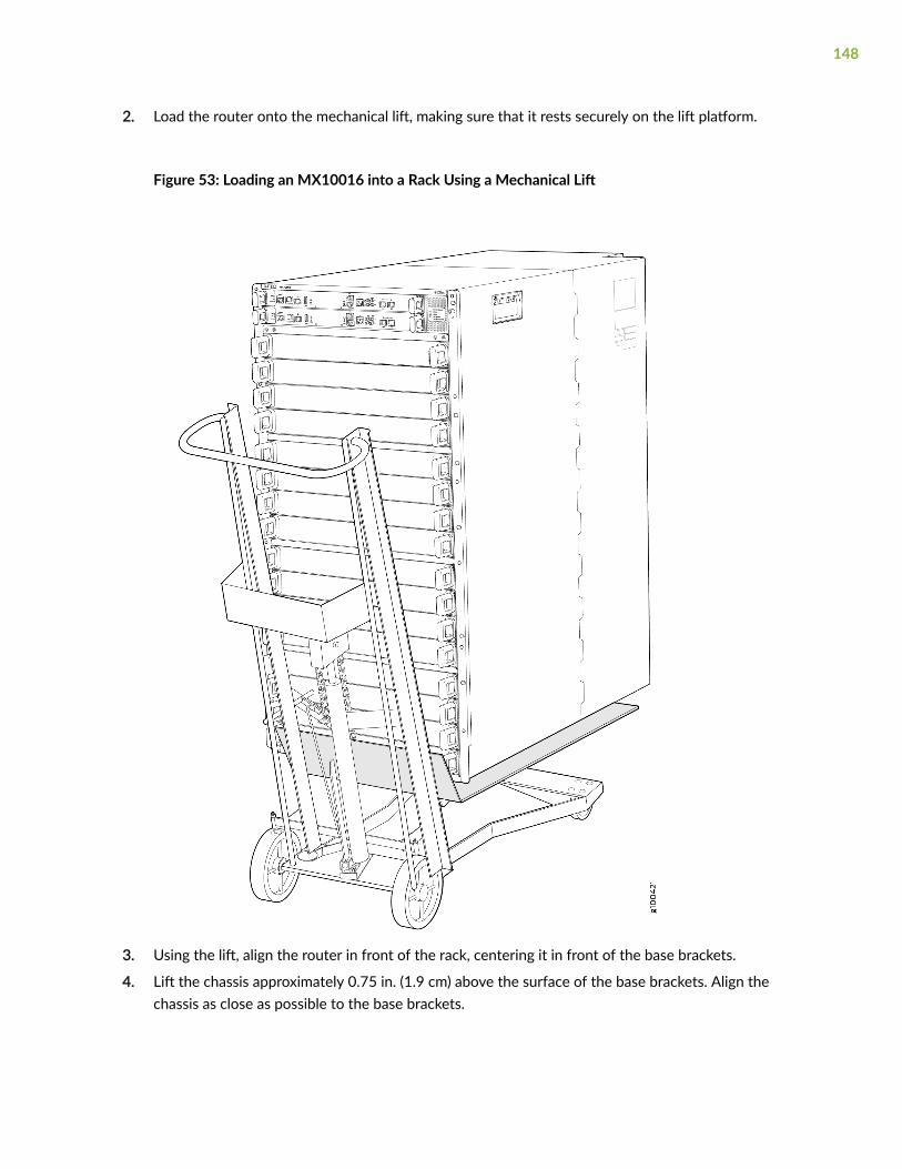
2. Load the router onto the mechanical lift, making sure that it rests securely on the lift platform.
Figure 53: Loading an MX10016 into a Rack Using a Mechanical Lift
3. Using the lift, align the router in front of the rack, centering it in front of the base brackets.
4. Lift the chassis approximately 0.75 in. (1.9 cm) above the surface of the base brackets. Align thechassis as close as possible to the base brackets.
148
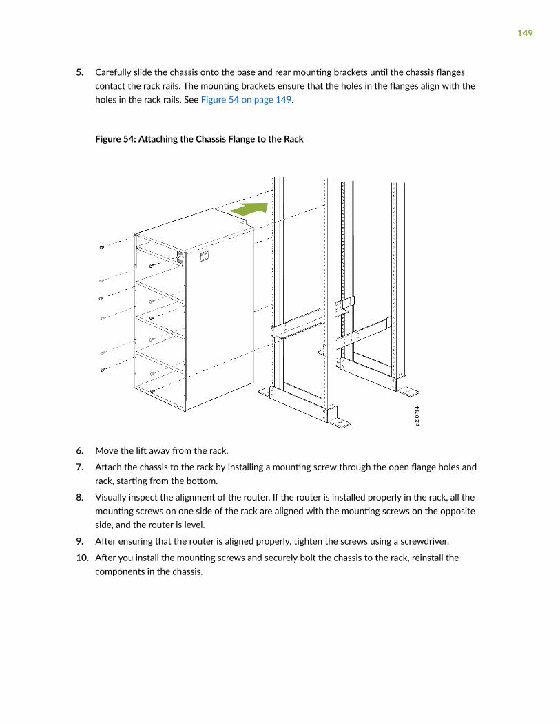
5. Carefully slide the chassis onto the base and rear mounting brackets until the chassis flangescontact the rack rails. The mounting brackets ensure that the holes in the flanges align with theholes in the rack rails. See Figure 54 on page 149.
Figure 54: Attaching the Chassis Flange to the Rack
6. Move the lift away from the rack.
7. Attach the chassis to the rack by installing a mounting screw through the open flange holes andrack, starting from the bottom.
8. Visually inspect the alignment of the router. If the router is installed properly in the rack, all themounting screws on one side of the rack are aligned with the mounting screws on the oppositeside, and the router is level.
9. After ensuring that the router is aligned properly, tighten the screws using a screwdriver.
10. After you install the mounting screws and securely bolt the chassis to the rack, reinstall thecomponents in the chassis.
149

Installing the Front Door on an MX10016
IN THIS SECTION
Before You Begin | 150
Install the Front Door | 151
Install the Air Filter in the MX100016 | 155
The front door is required on the MX10016 router to protect fiber optic cabling and to provideadditional protection from electromagnetic interference (EMI). The front door can be installed with orwithout the optional cable management system.
The front door is available in two models:
• JNP10016-FRNT-PNL, without an air filter
• JNP10016-FRPNL1, with an air filter
Both models are covered in the following procedures.
Before You Begin
Ensure you have the following tools and parts before you begin:
• A Phillips (+) screwdriver, number 2
• Front door (provided with the router chassis)
• Right base bracket (provided)
• Left base bracket (provided)
• Two interchangeable latch brackets (provided)
• Eight Phillips flat-head mounting screws (provided)
• Five cable seals - Three seals for the right side and two for the left side (provided)
150
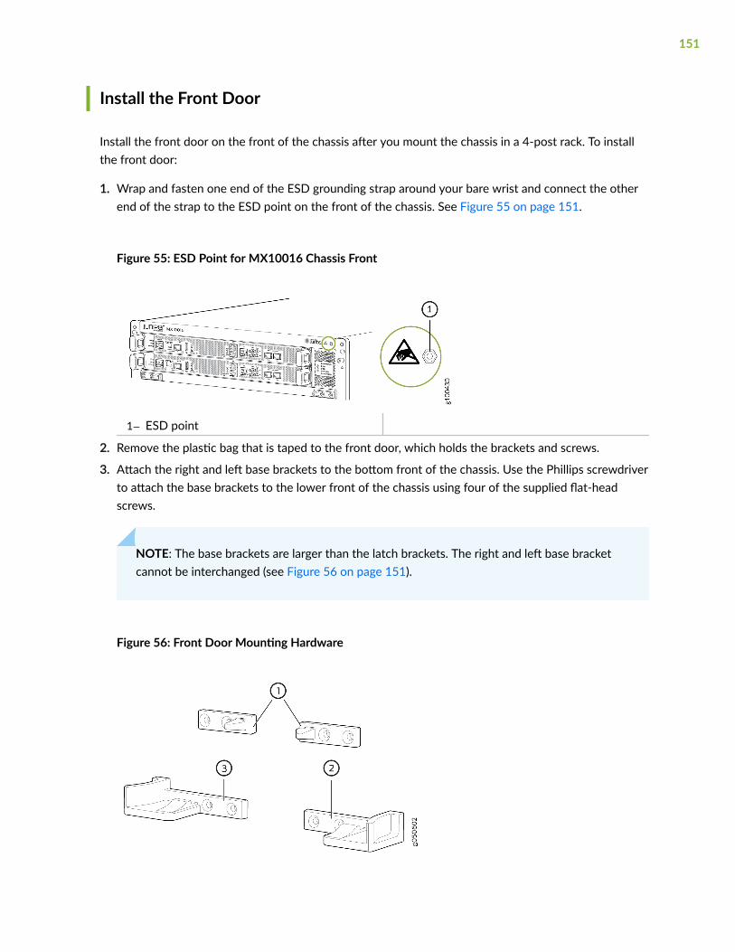
Install the Front Door
Install the front door on the front of the chassis after you mount the chassis in a 4-post rack. To installthe front door:
1. Wrap and fasten one end of the ESD grounding strap around your bare wrist and connect the otherend of the strap to the ESD point on the front of the chassis. See Figure 55 on page 151.
Figure 55: ESD Point for MX10016 Chassis Front
1— ESD point
2. Remove the plastic bag that is taped to the front door, which holds the brackets and screws.
3. Attach the right and left base brackets to the bottom front of the chassis. Use the Phillips screwdriverto attach the base brackets to the lower front of the chassis using four of the supplied flat-headscrews.
NOTE: The base brackets are larger than the latch brackets. The right and left base bracketcannot be interchanged (see Figure 56 on page 151).
Figure 56: Front Door Mounting Hardware
151
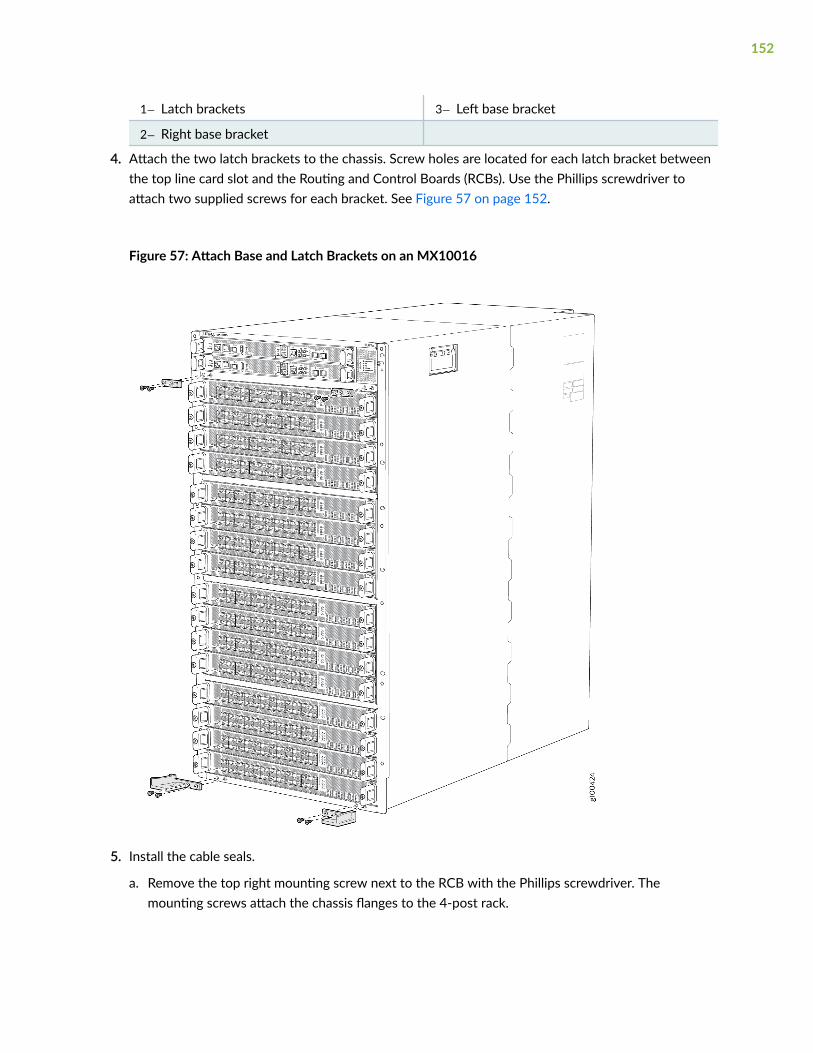
1— Latch brackets 3— Left base bracket
2— Right base bracket
4. Attach the two latch brackets to the chassis. Screw holes are located for each latch bracket betweenthe top line card slot and the Routing and Control Boards (RCBs). Use the Phillips screwdriver toattach two supplied screws for each bracket. See Figure 57 on page 152.
Figure 57: Attach Base and Latch Brackets on an MX10016
5. Install the cable seals.
a. Remove the top right mounting screw next to the RCB with the Phillips screwdriver. Themounting screws attach the chassis flanges to the 4-post rack.
152
b. Align the hole of the RCB cable seal over the mounting hole in the flange. Fasten the seal andflange to the rack using the Phillips to tighten the mounting screw.
c. Identify and loosen the two mounting screws that correspond to the keyholes in the bottom cableseals. Align the bottom-right cable seal along the mounting screws next to bottom eight MPCslots. Loosen those two mounting screws .
d. Position the keyhole slots of the top cable seal over the mounting screws. The cable seals are notinterchangeable; be sure you Install the seals so that the keyhole slots are on the inside, next tothe MPC. See Figure 58 on page 153.
Figure 58: Install the Cable Seals
1— RCB cable seal, install to the right of theRCBs
4— Lower-left cable seal
153

2— Upper-right cable seal 5— Upper-left cable seal
3— Lower-right cable seal
e. Slide the keyhole slot down behind the mounting screws and tighten the mounting screw with aPhillips screwdriver.
f. Repeat Step 5.c through Step 5.e on the opposite side of the chassis for the lower-left cable seal.
g. Identify and loosen the three mounting screws that correspond to the keyholes in the top cableseals. Align the top-right cable seal along the mounting screws next to top eight MPC slots.Loosen those three mounting screws.
h. Position the keyhole slots of the bottom cable seal over the mounting screws. The cable seals arenot interchangeable; be sure you Install the seals so that the keyhole slots are on the inside, nextto the MPC. See Figure 58 on page 153.
i. Slide the keyhole slot down behind the mounting screws and tighten the mounting screw with aPhillips screwdriver.
j. Repeat Step 5.g through Step 5.i on the opposite side of the chassis for the upper-left cable seal.
6. If you have not yet installed the MPCs, or the optional cable management system, do that nowbefore attaching the door. See "Removing and Installing MX10016 MPC Components" on page 241and "Install the Cable Management System" on page 250.
7. Set the front door into place.
a. Lift the front door and rest it on the two base brackets.
8. Slide the door back on the bracket glides until it engages on the two ramps.
154

9. Tilt the door towards the chassis until it is vertical with the chassis. The blue release buttons on theside of the door click into place (see Figure 59 on page 155 ).
Figure 59: Install the Front Panel on an MX10016
Install the Air Filter in the MX100016
If you have the JNP100016-FRPNL1 model of the front door, there is also an air filter to install. Readand follow the following procedure to add the air filter.
To install the air filter in the front door:
155

1. Wrap and fasten one end of the ESD grounding strap around your bare wrist and connect the otherend of the strap to the ESD point on the front of the chassis. See Figure 60 on page 156.
Figure 60: ESD Point for MX10016 Chassis Front
1— ESD point
156

2. Turn the knob of the air filter frame anti-clockwise and move it over the top of the front door. SeeFigure 61 on page 157.
Figure 61: Air Filter Frame in an MX10016 Front Door
1— Air filter frame
CAUTION: Always keep the air filter in place while the device is operating. Becausethe fans are very powerful, they could pull small bits of wire or other materials into thechassis through the unfiltered air intake. This could damage the components.
CAUTION: Do not run the router for more than a few minutes without the air filter inplace.
157
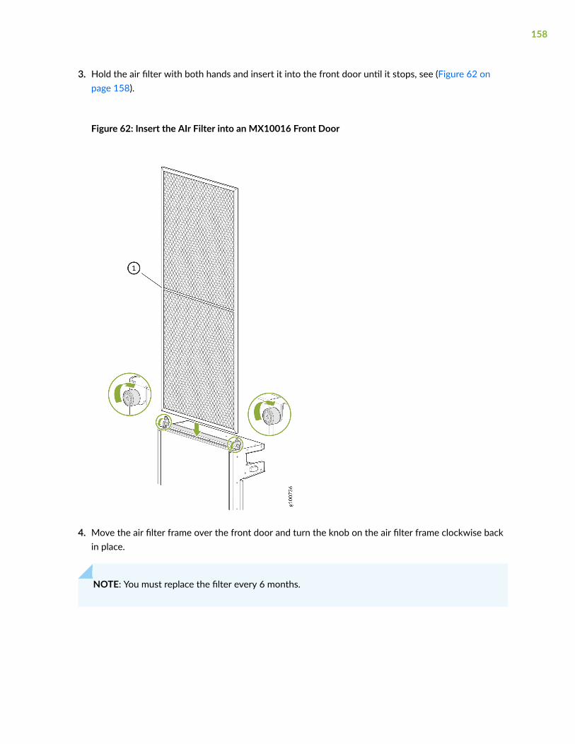
3. Hold the air filter with both hands and insert it into the front door until it stops, see (Figure 62 onpage 158).
Figure 62: Insert the AIr Filter into an MX10016 Front Door
4. Move the air filter frame over the front door and turn the knob on the air filter frame clockwise backin place.
NOTE: You must replace the filter every 6 months.
158

Connecting an MX10016 to Power
IN THIS SECTION
Connect an MX10016 to Earth Ground | 159
Connecting AC Power to an MX10016 | 161
Connecting DC Power to an MX10016 | 162
Connect an MX10016 to Earth Ground
To ensure proper operation and to meet safety and electromagnetic interference (EMI) requirements,you must connect the chassis to earth ground before you connect power to the device.
You must install the MX10016 in a restricted-access location and ensure that the chassis is alwaysproperly grounded. The MFX10016 has a two-hole protective grounding terminal provided on thechassis. See Figure 64 on page 161. Under all circumstances, use this grounding connection to groundthe chassis. For AC-powered systems, you must also use the grounding wire in the AC power cord alongwith the two-hole grounding lug connection. This tested system meets or exceeds all applicable EMCregulatory requirements with the two-hole protective grounding terminal.
Before you connect earth ground to the protective earthing terminal of an MX10016, ensure that alicensed electrician has attached an appropriate grounding lug to the grounding cable. Using a groundingcable with an incorrectly attached lug can damage the router.
NOTE: Mount your router in the rack before attaching the grounding lug to the router. See"Installing an MX10016 into a Four-Post Rack" on page 146
Ensure that you have the following parts and tools available:
• An electrostatic discharge (ESD) grounding strap (provided).
• Protective earthing terminal lug (provided).
• Grounding cable for your MX10016 (not provided)—The grounding cable must be a 6 AWG (13.3mm²), minimum 90° C wire, or as permitted by the local code.
159

• Grounding lug for your grounding cable (provided)—This bracket attaches to the lower left corner ofthe MX10016 router chassis next to PSU 9, providing a protective earthing terminal for the router.The grounding lug required is a Panduit LCD6-10A-L or equivalent.
• A Phillips screwdriver to tighten the two screws that are mounted on the chassis.
An AC-powered MX10016 gains additional grounding when you plug the power supply in the routerinto a grounded AC power outlet by using an AC power cord appropriate for your geographical location(see "MX10016 Power Cord Specifications" on page 110).
To connect an MX10016 chassis to earth ground:
1. Verify that a licensed electrician has attached the grounding lug (provided in the accessory kit) to thegrounding cable.
2. Connect the other end of the grounding cable to a proper earth ground, such as the rack in which therouter is mounted.
3. Attach an ESD grounding strap to your bare wrist, and connect the strap to the ESD grounding pointnext to the earthing posts (see Figure 63 on page 160).
Figure 63: ESD Point on the Rear of an MX10016
1— ESD point
4. Remove the two screws on the chassis grounding point using a Phillips screwdriver.
160

5. Place the chassis grounding lug and cable over the PEM nuts with the cable connection pointing tothe left (see Figure 64 on page 161).
Figure 64: Connecting a Grounding Cable to an MX10016
6. Place the two screws over the grounding lug and grounding cable.
7. Tighten the two 10-32 screws using a Phillips screwdriver applying torque between of 30.1 in.-lb (3.4N-m) and 42.04 in.-lb (4.75 N-m).
8. Dress the grounding cable and ensure that it does not touch or block access to other devicecomponents and that it does not drape where people could trip over it.
Connecting AC Power to an MX10016
Before you begin connecting power to the router, be sure you understand how to prevent ESD damage(see "Prevention of Electrostatic Discharge Damage" on page 321).
After you ground the chassis, connect the power supplies, and supply power to the chassis, the systeminitiates the power-on sequence. Although this sequence can start incrementally with a single powersupply, we recommend that you power on an MX10016 router with at least three power supplies.
To connect AC power to an MX10016 chassis:
1. Connect the chassis to earth ground (see Connect an MX10016 to Earth Ground).
161

CAUTION: To meet safety and electromagnetic interference (EMI) requirements and toensure proper operation, an MX10016 must be adequately grounded before it isconnected to power.
For installations that require a separate grounding conductor attached to the chassis,use the protective earthing terminal on the rear panel of the MX10016 to connect toearth ground.
An AC- powered MX10016 gets additional grounding when you plug the power supplyin the router into a grounded AC power outlet by using an AC power cord appropriatefor your geographical location. See "MX10016 Power Cord Specifications" on page110.
2. Install power supplies in the router, and apply power. See "How to Install a JNP10K-PWR-AC PowerSupply" on page 191.
Connecting DC Power to an MX10016
Before you begin connecting power to the router, be sure you understand how to prevent electrostaticdischarge (ESD) damage. See "Prevention of Electrostatic Discharge Damage" on page 321.
The overall process of powering on a DC-powered chassis involves the proper cabling of the individualpower supplies, adding the power supplies to the chassis, and supplying power. Although this sequencecan start incrementally with a single power supply, we recommend that you power on an MX10016router with at least three power supplies.
Each power supply input feed must be connected to a dedicated DC power source outlet.
To connect DC power to an MX10016 DC power supply, see "How to Install a JNP10K-PWR-DC PowerSupply" on page 207.
RELATED DOCUMENTATION
MX10016 Power System | 50
Removing and Installing MX10016 Power System Components | 188
Prevention of Electrostatic Discharge Damage | 321
General Safety Guidelines and Warnings | 296
Grounded Equipment Warning | 308
162

Connecting an MX10016 to External Devices
IN THIS SECTION
Connecting an MX10016 to a Network for Out-of-Band Management | 163
Connecting an MX10016 Router to a Management Console | 164
Connecting an MX10016 to a Network for Out-of-Band Management
Ensure that you have an appropriate cable available. See "Cable Specifications for Console andManagement Connections" on page 123.
You can monitor and manage an MX10016 using a dedicated management channel. Each Routing andControl Board (RCB) of an MX10016 has two management ports: a 10/100/1000BASE-T RJ-45 port forcopper connections and a 1-Gigabit SFP port for fiber connections. Use the management ports toconnect the RCB to a network for out-of-band management.
NOTE: You cannot use the management ports to perform the initial configuration of anMX10016. You must configure the management ports before you can successfully connect to theMX10016 using these ports. See "Configuring an MX10016 Router" on page 165.
To connect an MX10016 to a network for out-of-band management (see Figure 65 on page 164):
1. Connect one end of the cable to one of the two management ports (labeled MGMT) on one of theRCBs.
163

2. Connect the other end of the cable to the management device.
Figure 65: Connecting an MX10016 to a Network for Out-of-Band Management
Connecting an MX10016 Router to a Management Console
Ensure that you have an RJ-45 to DB-9 rollover cable available. An RJ-45 cable with an RJ-45 to DB-9adapter is provided with the device.
NOTE: If your laptop or PC does not have a DB-9 plug connector pin and you want to connectyour laptop or PC directly to the MX10016 router, use a combination of the RJ-45 cable andRJ-45 to DB-9 adapter supplied with the device and a USB to DB-9 plug adapter. You mustprovide the USB to DB-9 plug adapter.
An MX10016 router has a console port with an RJ-45 connector. Use the console port to connect thedevice to a management console or to a console server.
To connect an MX10016 to a management console (see Figure 66 on page 165 and Figure 67 on page165):
1. Connect one end of the Ethernet cable to the console port (labeled CON).
164

2. Connect the other end of the Ethernet cable into a console server (see Figure 66 on page 165) or amanagement console (see Figure 67 on page 165).
Figure 66: Connecting an MX10016 Router to a Management Console Through a Console Server
Figure 67: Connecting an MX10016 Router Directly to a Management Console
Configuring an MX10016 Router
Before you begin connecting and configuring the router, set the following parameter values on theconsole server or PC:
• Baud Rate—9600
• Flow Control—None
• Data—8
• Parity—None
• Stop Bits—1
• DCD State—Disregard
You must perform the initial configuration of an MX10016 router through the console port by using thecommand-line interface (CLI).
165
To connect and configure the router from the console:
1. Connect the console port (labeld CON) to a laptop or PC using the supplied RJ-45 cable and RJ-45to DB-9 adapter. The console port is located on the Routing and Control Board of the router.
2. Log in as root. A password is not required to log in as root. If the software boots before youconnected to the console port, you might need to press the Enter key for the prompt to appear.
login: root
3. Start the CLI.
root@% cli
4. Enter configuration mode.
root> configure
5. Add a password to the root administration user account.
[edit]root@# set system root-authentication plain-text-passwordNew password: passwordRetype new password: password
6. (Optional) Configure the name of the router. If the name includes spaces, enclose the name inquotation marks (“ ”).
[edit]root@# set system host-name host-name
7. Configure the default gateway.
[edit]root@# set routing-options static route default next-hop address
166

8. Configure the IP address and prefix length for the router management interface.
[edit]root@# set interfaces em0 unit 0 family inet address address/prefix-length
CAUTION: Although the CLI permits you to configure two management Ethernetinterfaces within the same subnet, only one interface is usable and supported.
NOTE: The management ports em0 (MGMT for RJ-45 connections), and em1 (also labeledMGMT for fiber connections) are located on the Routing and Control Boards of anMX10016.
9. (Optional) Configure the static routes to remote prefixes with access to the management port.
[edit]root@# set routing-options static route remote-prefix next-hop destination-ip retain no-readvertise
10. Enable Telnet service.
[edit]root@# set system services telnet
NOTE: When Telnet is enabled, you cannot log in to an MX10016 through Telnet using rootcredentials. Root login is allowed only for SSH access.
11. Commit the configuration to activate it on the router.
[edit] root@# commit
RELATED DOCUMENTATION
MX10016 System Overview | 2
167

MX10016 Installation Overview | 133
168
4CHAPTER
Maintaining Components
Field-Replaceable Units in an MX10016 | 170
Removing and Installing Routing and Control Boards | 172
Removing and Installing MX10016 Cooling System Components | 178
Removing and Installing MX10016 Power System Components | 188
Removing and Installing MX10016 Switch Fabric Boards | 229
Removing and Installing MX10016 MPC Components | 241
Removing and Installing Transceivers and Fiber-Optic Cables | 254
Removing an MX10016 Router | 262
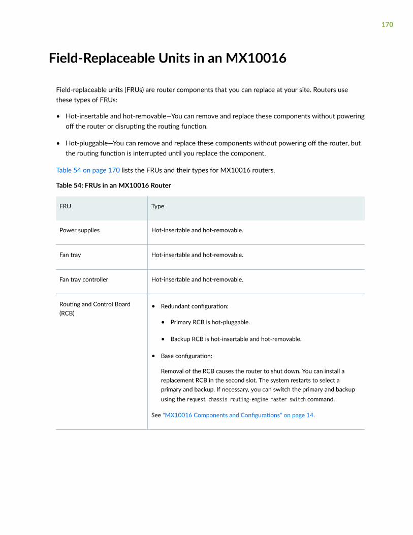
Field-Replaceable Units in an MX10016
Field-replaceable units (FRUs) are router components that you can replace at your site. Routers usethese types of FRUs:
• Hot-insertable and hot-removable—You can remove and replace these components without poweringoff the router or disrupting the routing function.
• Hot-pluggable—You can remove and replace these components without powering off the router, butthe routing function is interrupted until you replace the component.
Table 54 on page 170 lists the FRUs and their types for MX10016 routers.
Table 54: FRUs in an MX10016 Router
FRU Type
Power supplies Hot-insertable and hot-removable.
Fan tray Hot-insertable and hot-removable.
Fan tray controller Hot-insertable and hot-removable.
Routing and Control Board(RCB)
• Redundant configuration:
• Primary RCB is hot-pluggable.
• Backup RCB is hot-insertable and hot-removable.
• Base configuration:
Removal of the RCB causes the router to shut down. You can install areplacement RCB in the second slot. The system restarts to select aprimary and backup. If necessary, you can switch the primary and backupusing the request chassis routing-engine master switch command.
See "MX10016 Components and Configurations" on page 14.
170

Table 54: FRUs in an MX10016 Router (Continued)
FRU Type
Switch Fabric Boards (SFBs) Hot-insertable and hot-removable.
We recommend that you take the SFBs offline before removing them to avoidtraffic loss while the router fabric is being reconfigured. You can take SFBsoffline by using the request chassis sib (offline | online) slot slot-numberoffline command.
Line cards Hot-insertable and hot-removable.
We recommend that you take line cards offline before removing them. You cantake line cards offline by using the request chassis fpc slot slot-numberoffline command.
NOTE: Line cards are not part of the base configuration or redundantconfiguration. You must order them separately.
Optical transceivers Hot-insertable and hot-removable.
See "MX10016 Transceiver and Cable Specifications" on page 122 for theJunos OS release in which the transceivers were introduced.
NOTE: If you have a Juniper Care service contract, register any addition, change, or upgrade ofhardware components at https://www.juniper.net/customers/support/tools/updateinstallbase/.Failure to do so can result in significant delays if you need replacement parts. This note does notapply if you replace an existing component with the same type of component.
RELATED DOCUMENTATION
MX10016 Transceiver and Cable Specifications | 122
171

Removing and Installing Routing and Control Boards
IN THIS SECTION
How to Handle and Store an MX10016 Routing and Control Board | 172
Removing a Routing and Control Board | 174
Installing a Routing and Control Board | 176
How to Handle and Store an MX10016 Routing and Control Board
IN THIS SECTION
Handling Routing and Control Boards | 172
Storing RCBs | 173
The MX10016 chassis has several field-replaceable units (FRUs) that have fragile components. To avoiddamaging the routing and control boards (RCBs), you must follow safe handling practices.
Handling Routing and Control Boards
Pay proper attention to how you are handling Routing and Control Boards (RCBs). Because RCBs areinstalled horizontally, we recommend that you hold them by the sides of the units when they are not inthe chassis.
To handle an RCB properly:
1. Orient the RCB so that the faceplate of the unit is toward you.
2. Grasp each side of the unit firmly as you slide the unit out of the chassis.
3. Take care not to strike the unit against any object as you carry it.
172

CAUTION: Never hold an RCB by the connector edge. The connectors are fragile. Youcannot seat an RCB properly if the connectors are damaged.
4. If you must rest an RCB on an edge, place a cushion between the connector edge and the surface.
CAUTION: Do not stack RCBs on top of one another or on top of any othercomponent.
5. Place each RCB in an individual electrostatic bag or separately on an antistatic mat that is placed on aflat, stable surface.
Storing RCBs
You must store RCBs either in the chassis or in a spare shipping container, horizontally and sheet-metalside down. Do not stack these units on top of one another or on top of any other component. Placeeach unit in an individual electrostatic bag or separately on an antistatic mat placed on a flat, stablesurface.
NOTE: Because RCBs are heavy, and because electrotatic bags are fragile, inserting an RCB intothe bag is best done by two people.
To insert an RCB into an electrostatic bag with the help of another person:
1. Hold the unit horizontally with the faceplate toward you.
2. Have the second person slide the opening of the electrostatic bag over the connector edge and thenpull the bag to cover the unit.
To insert an RCB into a bag by yourself:
1. Lay the unit horizontally on an antistatic mat that is on a flat, stable surface, with the sheet-metalside of the unit facing down.
2. Orient the unit with the faceplate toward you.
3. Carefully insert the connector edge into the opening of the bag, and then pull the bag toward you tocover the unit.
173

Removing a Routing and Control Board
An MX10016 can have one or two Routing and Control Boards (RCBs), depending on the configuration.You can install an RCB in either of the two top slots on the front of the chassis.
In redundant configurations, an RCB is a hot-removable and hot-insertable field-replaceable unit (FRU).In base configurations, you need to install a second RCB before removing a failing RCB in order toprevent the router from shutting down. We recommend that you take base systems off before replacingthe RCB.
Before you remove an RCB, ensure that you have the following items:
• An electrostatic discharge (ESD) grounding strap
• An antistatic mat
• Cover panel for the empty slot if you are not replacing the RCB.
CAUTION: In base configurations, removal of the RCB causes the system to shut down.In redundant configurations, removal of the RCB causes the system to reboot and startthe selection process for a new primary RCB.
To remove an RCB:
1. Place an antistatic bag or antistatic mat on a flat, stable surface.
2. Use the following CLI commands to take the RCB offline.
user@host>request vmhost power-off other-routing enginePower-off the vmhost ? (yes,no?yesInitiating vmhost shutdown...warning: Initiating Junos shutdown...shutdown: [pid 42862]Shutdown NOW!
user@host>request chassis cb slot slot-number offline
174

You can use the show chassis environment cb | match State CLI command to verify that the RCB is offline.
user@host>show chassis environment cb | match StateState Online Master State Offline
3. Wrap and fasten one end of an ESD strap around your bare wrist, and connect the other end of thestrap to the ESD point on the chassis (see Figure 68 on page 175).
Figure 68: ESD Point on the Front of an MX10016
4. Simultaneously rotate the RCB handles counterclockwise to unseat the RCB.
5. Grasp both the handles, and slide the RCB about halfway out of the chassis (see Figure 69 on page175).
Figure 69: Removing a Routing and Control Board
6. Grasp each side of the RCB and slide it completely out of the chassis.
7. Place the RCB on the antistatic mat.
175

8. If you are not replacing the RCB now, install a cover panel in the empty slot.
Installing a Routing and Control Board
An MX10016 can have one or two Routing and Control Boards (RCBs), depending on the configuration.RCBs can be installed in either of the two top slots on the front of the chassis.
In redundant configurations, an RCB is a hot-removable and hot-insertable field-replaceable unit (FRU).In base configurations, you need to install a second RCB before removing a failing RCB in order toprevent the router from shutting down.
Before you install a RCB, ensure that you have an electrostatic discharge (ESD) grounding strap.
To install an RCB:
1. Wrap and fasten one end of an ESD strap around your bare wrist, and connect the other end of thestrap to the ESD point on the front of an MX10016 (see Figure 70 on page 176).
Figure 70: ESD Point on the Front of an MX10016
176
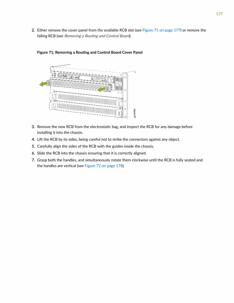
2. Either remove the cover panel from the available RCB slot (see Figure 71 on page 177) or remove thefailing RCB (see Removing a Routing and Control Board).
Figure 71: Removing a Routing and Control Board Cover Panel
3. Remove the new RCB from the electrostatic bag, and inspect the RCB for any damage beforeinstalling it into the chassis.
4. Lift the RCB by its sides, being careful not to strike the connectors against any object.
5. Carefully align the sides of the RCB with the guides inside the chassis.
6. Slide the RCB into the chassis ensuring that it is correctly aligned.
7. Grasp both the handles, and simultaneously rotate them clockwise until the RCB is fully seated andthe handles are vertical (see Figure 72 on page 178).
177

The RCB begins the power-on sequence after it is fully seated.
Figure 72: Routing and Control Board Installation
8. To verify that the RCB is functioning normally, check the PWR LED on its faceplate and theCONTROL BOARDS LED on the status panel. Both LEDs should light steadily shortly after the RCB isinstalled. If the PWR LED is blinking yellow, there might be insufficient power available.
You can also use the the show chassis environment cb command to verify that the RCB is online.
See "Power Requirements for MX10016 Components" on page 100 to ensure that you haveadequate power for the newly installed RCB.
Removing and Installing MX10016 Cooling SystemComponents
IN THIS SECTION
Removing an MX10016 Fan Tray | 179
Installing an MX10016 Fan Tray | 182
Removing an MX10016 Fan Tray Controller | 184
Installing an MX10016 Fan Tray Controller | 186
178

An MX10016 router has two independent, field-replaceable fan trays. Fan trays must be replaced withinthe duration mentioned in Table 55 on page 179.
Table 55: Replacement Duration for the Fan Tray of an MX10016
Chassis Ambient Temperature Duration
27°C 3 minutes
35°C 2 minutes 46 seconds
40°C 2 minutes
NOTE: When replacing the fans or SIBs at 40°C chassis ambient temperature, ensure that thefans run at 100% fan speed for at least 10 minutes before replacing the fans or SIBs.
Use the test chassis fan tray 0 speed minutesfull-speed and test chassis fan tray 1 speed full-speedcommands to set the chassis fans to 100% speed.
To install or remove the fan trays and fan tray controller, see the following sections:
Removing an MX10016 Fan Tray
Before you remove a fan tray:
• Ensure you understand how to prevent ESD damage (see "Prevention of Electrostatic DischargeDamage" on page 321).
• Ensure that you have the following parts and tools available to remove a fan tray:
• Electrostatic discharge (ESD) grounding strap
• A Phillips (+) screwdriver, number 1 or 2 (optional), for the captive screws
An MX10016 has two independent, field-replaceable fan trays. Each fan tray is a hot-removable andhot-insertable field-replaceable unit (FRU); you can remove and replace the fan tray while the router isrunning without turning off power to the router or disrupting routing functions.
179
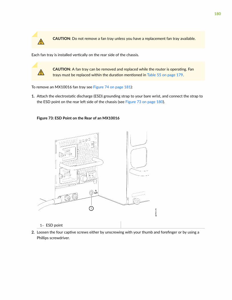
CAUTION: Do not remove a fan tray unless you have a replacement fan tray available.
Each fan tray is installed vertically on the rear side of the chassis.
CAUTION: A fan tray can be removed and replaced while the router is operating. Fantrays must be replaced within the duration mentioned in Table 55 on page 179.
To remove an MX10016 fan tray see Figure 74 on page 181):
1. Attach the electrostatic discharge (ESD) grounding strap to your bare wrist, and connect the strap tothe ESD point on the rear left side of the chassis (see Figure 73 on page 180).
Figure 73: ESD Point on the Rear of an MX10016
1— ESD point
2. Loosen the four captive screws either by unscrewing with your thumb and forefinger or by using aPhillips screwdriver.
180
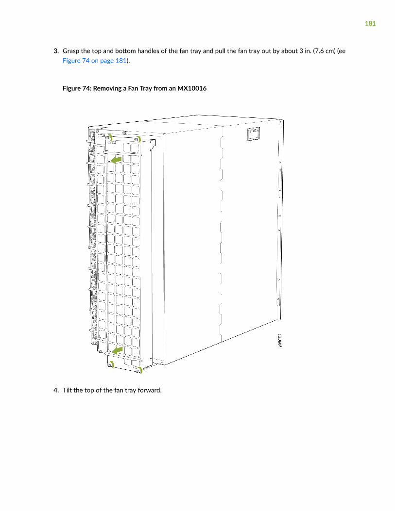
3. Grasp the top and bottom handles of the fan tray and pull the fan tray out by about 3 in. (7.6 cm) (eeFigure 74 on page 181).
Figure 74: Removing a Fan Tray from an MX10016
4. Tilt the top of the fan tray forward.
181

CAUTION: See the heat symbol
on the fan tray. The fan tray handle and its surfaces, including the power supplyhandles may be hot. Wear proper protective, heat-resistant, gloves while removing thefan tray.
5. Using both hands, lift the fan tray out of the slot and rest it on a flat surface with the handles to theside.
CAUTION: Fan trays must be replaced within the duration mentioned in Table 55 onpage 179.
Installing an MX10016 Fan Tray
Before install a fan tray:
• Ensure you understand how to prevent ESD damage (see "Prevention of Electrostatic DischargeDamage" on page 321).
Ensure that you have the following parts and tools available to install a fan tray:
• Electrostatic discharge (ESD) grounding strap
• A Phillips (+) screwdriver, number 1 or 2 (optional), for the captive screws
• A replacement fan tray
CAUTION: A fan tray can be removed and replaced while the router is operating.Fantrays must be replaced within the duration mentioned in Table 55 on page 179.
An MX10016 chassis has two independent, field-replaceable fan trays. Each fan tray is a hot-removableand hot-insertable field-replaceable unit (FRU); you can remove and replace the fan tray while the routeris running without turning off power to the router or disrupting routing functions.
182

To install an MX10016 fan tray (see Figure 76 on page 184):
1. Wrap and fasten one end of an ESD strap around your bare wrist, and connect the other end of thestrap to the ESD point on the rear left side of the chassis (see Figure 75 on page 183 ).
Figure 75: ESD Point on the Rear of an MX10016
1— ESD point
2. Grasp the top and bottom fan tray handles, and align the bottom of the fan tray with the bottom ofthe fan tray slot.
3. Rest the bottom edge of the fan tray in the slot, and slide the fan tray into place so that the fan trayis fully seated.
183

4. Tighten the captive screws on the faceplate of the fan tray by using your fingers. If you are unable totighten the captive screws by using your fingers, use the screwdriver.
Figure 76: Installing a Fan Tray in an MX10016
Removing an MX10016 Fan Tray Controller
For each of the two fan trays, there is a fan tray controller. Each controller is a hot-removable and hot-insertable field-replaceable unit (FRU); you can remove and replace one fan tray controller while the
184
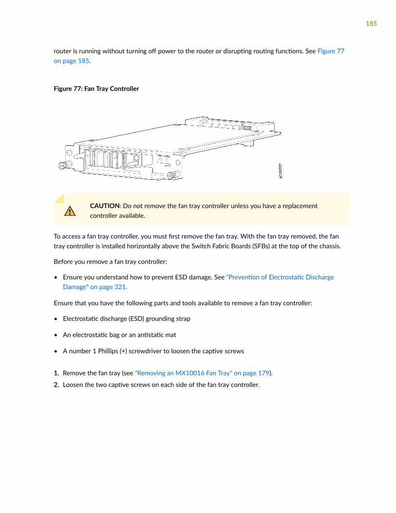
router is running without turning off power to the router or disrupting routing functions. See Figure 77on page 185.
Figure 77: Fan Tray Controller
CAUTION: Do not remove the fan tray controller unless you have a replacementcontroller available.
To access a fan tray controller, you must first remove the fan tray. With the fan tray removed, the fantray controller is installed horizontally above the Switch Fabric Boards (SFBs) at the top of the chassis.
Before you remove a fan tray controller:
• Ensure you understand how to prevent ESD damage. See "Prevention of Electrostatic DischargeDamage" on page 321.
Ensure that you have the following parts and tools available to remove a fan tray controller:
• Electrostatic discharge (ESD) grounding strap
• An electrostatic bag or an antistatic mat
• A number 1 Phillips (+) screwdriver to loosen the captive screws
1. Remove the fan tray (see "Removing an MX10016 Fan Tray" on page 179).
2. Loosen the two captive screws on each side of the fan tray controller.
185

3. Grasp the fan tray controller, and pull it straight out of the slot (see Figure 78 on page 186).
Figure 78: Removing an MX10016 Fan Tray Controller
4. Place the fan tray controller in an electrostatic bag or on an antistatic mat.
Installing an MX10016 Fan Tray Controller
Each fan tray of an MX10016 has a fan tray controller (see Figure 79 on page 186). Each controller is ahot-removable and hot-insertable field-replaceable unit (FRU). You can remove and replace one fan traycontroller while the router is running without turning off power to the router or disrupting routingfunctions.
Figure 79: Fan Tray Controller
186

CAUTION: Do not remove a fan tray controller unless you have a replacement fan traycontroller available.
To access a fan tray controller, you must first remove the associated fan tray. With the fan tray removed,the fan tray controller is installed horizontally above the Switch Fabric Boards (SFBs) at the top of thechassis.
Before you replace a fan tray controller:
• Ensure you understand how to prevent ESD damage. See "Prevention of Electrostatic DischargeDamage" on page 321.
• You must have removed the associated fan tray. See "Removing an MX10016 Fan Tray" on page 179.
Ensure that you have the following parts and tools available to install a fan tray controller:
• Electrostatic discharge (ESD) grounding strap
• A number 1 Phillips (+) screwdriver to tighten the captive screws.
• Replacement fan controller
To install a fan tray controller:
1. Remove the replacement fan tray controller from the electrostatic bag.
2. Carefully slide the fan tray controller into the fan tray controller slot until it is flush with themounting holes (see Figure 80 on page 187).
Figure 80: Replacing an MX10016 Fan Tray Controller
187

3. Using a Phillips screwdriver, tighten the captive screws for the fan tray controller.
4. Replace the fan tray. See "Installing an MX10016 Fan Tray" on page 182.
Removing and Installing MX10016 Power SystemComponents
IN THIS SECTION
How to Remove a JNP10K-PWR-AC Power Supply | 188
How to Install a JNP10K-PWR-AC Power Supply | 191
How to Remove a JNP10K-PWR-AC2 Power Supply | 196
How to Install a JNP10K-PWR-AC2 Power Supply | 200
How to Remove a JNP10K-PWR-DC Power Supply | 204
How to Install a JNP10K-PWR-DC Power Supply | 207
How to Remove a JNP10K-PWR-DC2 Power Supply | 216
How to Install a JNP10K-PWR-DC2 Power Supply | 219
How to Remove a JNP10K-PWR-AC Power Supply
Before you remove an AC power supply from the chassis:
• Ensure you understand how to prevent ESD damage. See "Prevention of Electrostatic DischargeDamage" on page 321.
Ensure that you have the following parts and tools available to remove an AC power supply from anMX10016 router:
• Electrostatic discharge (ESD) grounding strap
• Phillips (+) screwdriver, number 1
• Replacement power supply or a cover panel for the power supply slot
188
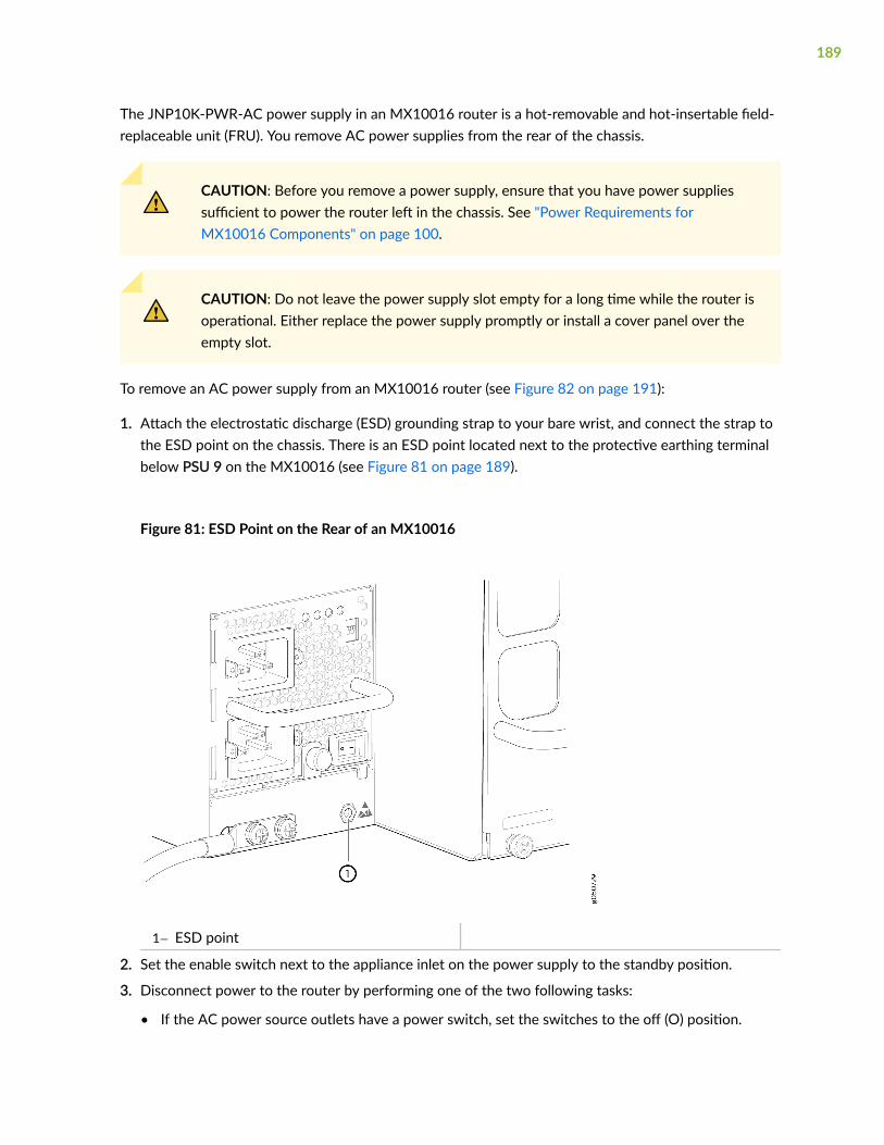
The JNP10K-PWR-AC power supply in an MX10016 router is a hot-removable and hot-insertable field-replaceable unit (FRU). You remove AC power supplies from the rear of the chassis.
CAUTION: Before you remove a power supply, ensure that you have power suppliessufficient to power the router left in the chassis. See "Power Requirements forMX10016 Components" on page 100.
CAUTION: Do not leave the power supply slot empty for a long time while the router isoperational. Either replace the power supply promptly or install a cover panel over theempty slot.
To remove an AC power supply from an MX10016 router (see Figure 82 on page 191):
1. Attach the electrostatic discharge (ESD) grounding strap to your bare wrist, and connect the strap tothe ESD point on the chassis. There is an ESD point located next to the protective earthing terminalbelow PSU 9 on the MX10016 (see Figure 81 on page 189).
Figure 81: ESD Point on the Rear of an MX10016
1— ESD point
2. Set the enable switch next to the appliance inlet on the power supply to the standby position.
3. Disconnect power to the router by performing one of the two following tasks:
• If the AC power source outlets have a power switch, set the switches to the off (Ο) position.
189
• If the AC power source outlets do not have a power switch, gently pull the plug end of the powercords out of the power source outlets.
4. Turn the adjustment nut of the power cord retainers counterclockwise until you can see the powercord. Pull the power cord out of the slot in the adjustment nut.
5. Remove the power cords from the AC inlet on the AC power supply faceplate.
6. Unscrew the captive screw counterclockwise by using the number 1 Phillips (+) screwdriver (seeFigure 82 on page 191).
7. Rotate the captive screw away from the faceplate of the power supply to release the latch.
8. Taking care not to touch the power supply output connections, pins, leads, or solder connections,place one hand under the power supply to support it. Grasp the power supply handle with your otherhand, and pull the power supply completely out of the chassis.
CAUTION: Do not strike the output connections of the power supply against anyobject. If the connection hits a solid object, it could damage the power supply.
CAUTION: See the heat symbol
. The power supply surfaces are hot. Allow a few minutes for the power supply to coolby pulling the power supply halfway out of the chassis, or wear protective, heat-resistant gloves while removing the power supply.
190

9. If you are not replacing the power supply, install the cover panel over the slot.
Figure 82: Removing a JNP10K-PWR-AC Power Supply from an MX10016
How to Install a JNP10K-PWR-AC Power Supply
Before you install an AC power supply in the router:
• Ensure you understand how to prevent ESD damage. See "Prevention of Electrostatic DischargeDamage" on page 321.
• If the AC power source outlets have a power switch, set them to the off (O) position.
Ensure that you have the following parts and tools available to install an AC power supply:
• Electrostatic discharge (ESD) grounding strap
• A number 1 Phillips (+) screwdriver
• Power cords appropriate for your geographical location. See "MX10016 Power Cord Specifications"on page 110.
• Power cord retainer clips
191

• Replacement power supply or a cover panel for the power supply slot
The JNP10K-PWR-AC power supply in an MX10016 chassis is a hot-insertable and hot-removable field-replaceable unit (FRU). You can install up to 10 power supplies in an MX10016 router chassis. All ACpower supplies install in the rear of the chassis in the slots provided along the left side.
CAUTION: Do not mix AC and DC power supplies in the same chassis.
NOTE: See the heat symbol
. Wear heat-resistant hand gloves while accessing the fan tray and power supply.
To install an AC power supply in an MX10016:
1. Attach the electrostatic discharge (ESD) grounding strap to your bare wrist, and connect the strapto the ESD point on the chassis.
192
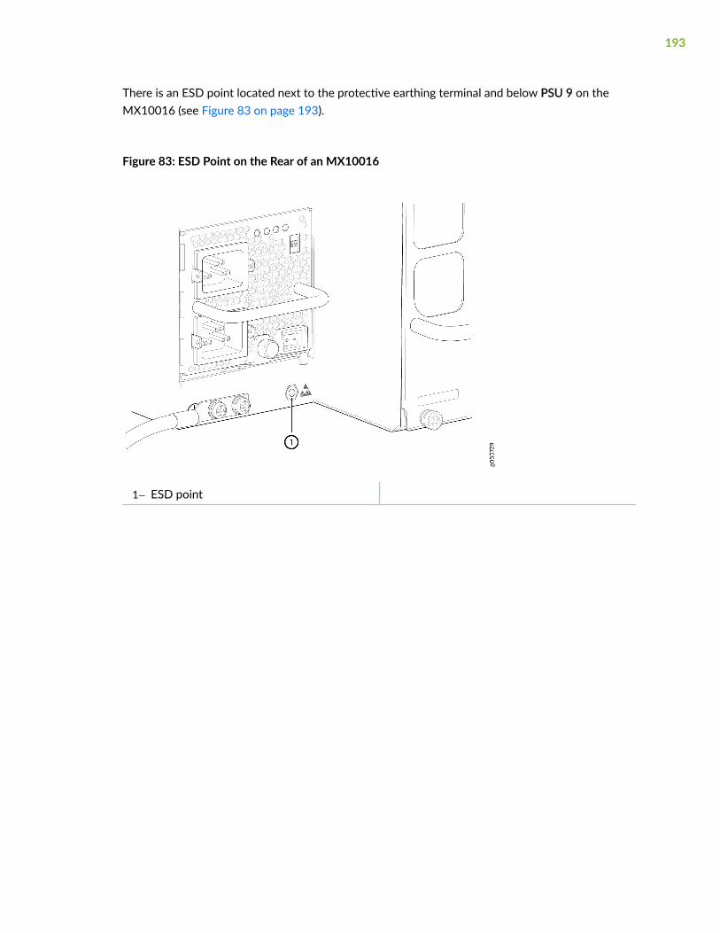
There is an ESD point located next to the protective earthing terminal and below PSU 9 on theMX10016 (see Figure 83 on page 193).
Figure 83: ESD Point on the Rear of an MX10016
1— ESD point
193

2. If the power supply slot has a cover panel on it, insert your thumb and forefinger into the fingerholes, and then squeeze and pull the cover panel out of the slot. Save the cover panel for later use(see Figure 84 on page 194 for removal on an MX10016).
Figure 84: Removing the PSU Cover Panel of a Power Supply on an MX10016
3. Taking care not to touch the power supply connections, remove the power supply from its bag.
4. Peel back and remove the protective plastic wrap that covers all four sides of the power supply.
5. Ensure the power switch on the power supply is set to the standby (O) position. This switch turnsoff the output voltage; it does not interrupt AC supply.
6. Unscrew the captive screw by turning it counterclockwise by using the number 1Phillips (+) screwdriver.
7. Rotate the captive screw away from the faceplate of the power supply to release the latch. You caninstall a power supply in any slot labeled PSU 0 through PSU 9 on an MX10016.
8. Using both hands, place the power supply in the power supply slot on the rear of the chassis.
9. Slide the power supply straight into the chassis until the power supply is fully seated in the slot.Ensure that the power supply faceplate is flush with any adjacent power supply faceplates or powersupply cover panels (see Figure 85 on page 195).
10. Push the captive screw into the power supply faceplate. Ensure that the screw is seated inside thecorresponding hole on the faceplate.
194
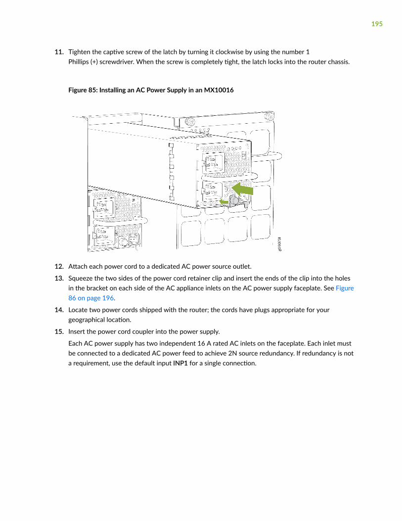
11. Tighten the captive screw of the latch by turning it clockwise by using the number 1Phillips (+) screwdriver. When the screw is completely tight, the latch locks into the router chassis.
Figure 85: Installing an AC Power Supply in an MX10016
12. Attach each power cord to a dedicated AC power source outlet.
13. Squeeze the two sides of the power cord retainer clip and insert the ends of the clip into the holesin the bracket on each side of the AC appliance inlets on the AC power supply faceplate. See Figure86 on page 196.
14. Locate two power cords shipped with the router; the cords have plugs appropriate for yourgeographical location.
15. Insert the power cord coupler into the power supply.
Each AC power supply has two independent 16 A rated AC inlets on the faceplate. Each inlet mustbe connected to a dedicated AC power feed to achieve 2N source redundancy. If redundancy is nota requirement, use the default input INP1 for a single connection.
195
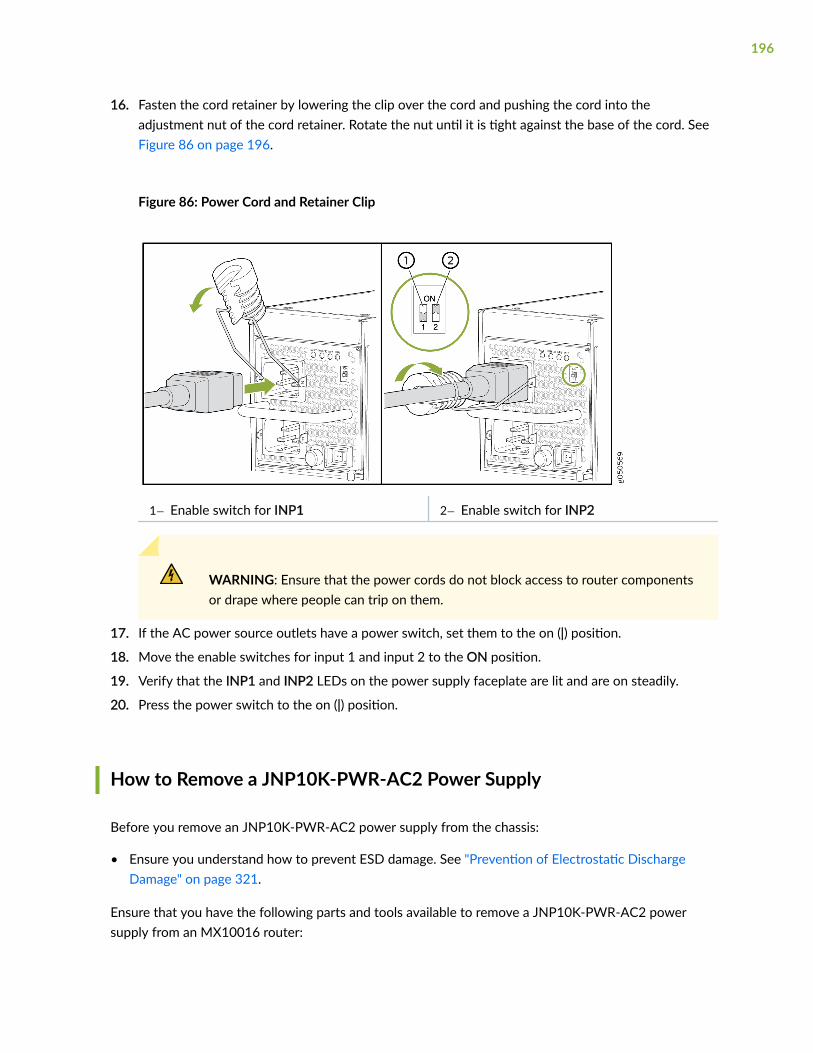
16. Fasten the cord retainer by lowering the clip over the cord and pushing the cord into theadjustment nut of the cord retainer. Rotate the nut until it is tight against the base of the cord. SeeFigure 86 on page 196.
Figure 86: Power Cord and Retainer Clip
1— Enable switch for INP1 2— Enable switch for INP2
WARNING: Ensure that the power cords do not block access to router componentsor drape where people can trip on them.
17. If the AC power source outlets have a power switch, set them to the on (|) position.
18. Move the enable switches for input 1 and input 2 to the ON position.
19. Verify that the INP1 and INP2 LEDs on the power supply faceplate are lit and are on steadily.
20. Press the power switch to the on (|) position.
How to Remove a JNP10K-PWR-AC2 Power Supply
Before you remove an JNP10K-PWR-AC2 power supply from the chassis:
• Ensure you understand how to prevent ESD damage. See "Prevention of Electrostatic DischargeDamage" on page 321.
Ensure that you have the following parts and tools available to remove a JNP10K-PWR-AC2 powersupply from an MX10016 router:
196

• Heat protective gloves able to withstand temperatures of 158°F (70°C)
• Electrostatic discharge (ESD) grounding strap
• Phillips (+) screwdriver, number 1
• Replacement power supply or a cover panel for the power supply slot
The JNP10K-PWR-AC2 power supply in an MX10016 chassis is a hot-removable and hot-insertablefield-replaceable unit (FRU). You remove all power supplies from the rear of the chassis.
WARNING: Protect yourself from severe burns by wearing heat-protective gloves whenremoving a working JNP10K-PWR-AC2 power supply from the chassis. These powersupplies can reach 158°F (70°C ).
CAUTION: Before you remove a power supply, ensure that you have power suppliessufficient to power the router left in the chassis. See "Power Requirements forMX10016 Components" on page 100.
CAUTION: Do not leave the power supply slot empty for a long time while the router isoperational. Either replace the power supply promptly or install a cover panel over theempty slot.
To remove a JNP10K-PWR-AC2 power supply from an MX10016 router:
197
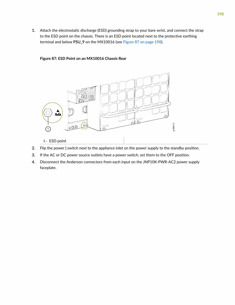
1. Attach the electrostatic discharge (ESD) grounding strap to your bare wrist, and connect the strapto the ESD point on the chassis. There is an ESD point located next to the protective earthingterminal and below PSU_9 on the MX10016 (see Figure 87 on page 198).
Figure 87: ESD Point on an MX10016 Chassis Rear
1— ESD point
2. Flip the power | switch next to the appliance inlet on the power supply to the standby position.
3. If the AC or DC power source outlets have a power switch, set them to the OFF position.
4. Disconnect the Anderson connectors from each input on the JNP10K-PWR-AC2 power supplyfaceplate.
198

5. Unscrew the captive screw counterclockwise by using the Phillips (+) screwdriver, number 1. SeeFigure 88 on page 199.
Figure 88: Removing a JNP10K-PWR-AC2 from an MX10016 Chassis
6. Rotate the captive screw away from the faceplate of the power supply to release the latch.
7. Put on your heat protective gloves before removing the power supply from the chassis.
8. Taking care not to touch the power supply output connections, pins, leads, or solder connections,place one hand under the power supply to support it. Grasp the power supply handle with yourother hand and pull the power supply completely out of the chassis.
CAUTION: Do not bump the output connections. If the connection hits a solidobject, it could damage the power supply.
9. Place the JNP10K-PWR-on an antistatic surface to completely cool before placing the powersupply in an antistatic bag for storage.
10. If you are not replacing the power supply, install the cover panel over the slot by inserting yourthumb and forefinger into the finger holes, squeezing and pulling the cover out of the slot. Do notrun the chassis without a power supply or cover panel in place.
199

How to Install a JNP10K-PWR-AC2 Power Supply
The JNP10K-PWR-AC2 power supply in an MX10016 chassis is a hot-insertable and hot-removablefield-replaceable unit (FRU). You can install up to 10 power supplies in a MX10016 router chassis. Allpower supplies install in the rear of the chassis in the slots provided along the left side.
CAUTION: Do not mix JNP10K-PWR-AC2 and JNP10K-PWR-DC2 power supplies inthe same running chassis.
WARNING: Protect yourself from severe burns by wearing heat-protective gloves whenremoving a running JNP10K-PWR-AC2 power supply from the chassis. The powersupply can reach 158°F (70°C).
Before you install a JNP10K-PWR-AC2 power supply in the chassis:
Ensure that you have followed all safety warnings and cautions:
• Ensure you understand how to prevent ESD damage. See "Prevention of Electrostatic DischargeDamage" on page 321.
• If the AC or DC power source outlets have a power switch, set them to the off (O) position.
Ensure that you have the following parts and tools available to install an JNP10K-PWR-AC2 powersupply:
• Electrostatic discharge (ESD) grounding strap
• Phillips (+) screwdriver, number 1
• Power cables appropriate for your geographical location (for low-voltage installations) or inputamperage (for high-voltage installations). See "MX10016 Power Cord Specifications" on page 110.HVAC and HVDC connectors and lugs must be installed by a qualified electrician before installation.
To install a JNP10K-PWR-AC2 power supply in an MX10016:
200
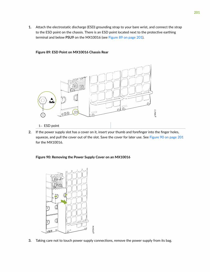
1. Attach the electrostatic discharge (ESD) grounding strap to your bare wrist, and connect the strapto the ESD point on the chassis. There is an ESD point located next to the protective earthingterminal and below PSU9 on the MX10016 (see Figure 89 on page 201).
Figure 89: ESD Point on MX10016 Chassis Rear
1— ESD point
2. If the power supply slot has a cover on it, insert your thumb and forefinger into the finger holes,squeeze, and pull the cover out of the slot. Save the cover for later use. See Figure 90 on page 201for the MX10016.
Figure 90: Removing the Power Supply Cover on an MX10016
3. Taking care not to touch power supply connections, remove the power supply from its bag.
201
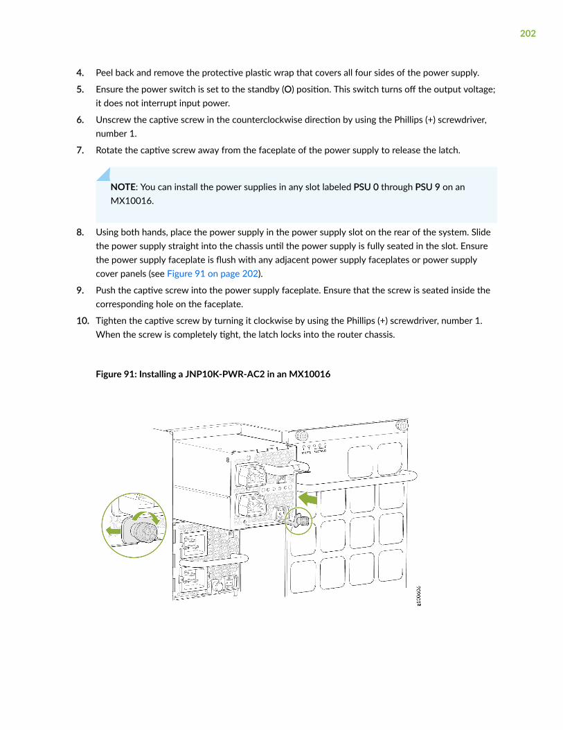
4. Peel back and remove the protective plastic wrap that covers all four sides of the power supply.
5. Ensure the power switch is set to the standby (O) position. This switch turns off the output voltage;it does not interrupt input power.
6. Unscrew the captive screw in the counterclockwise direction by using the Phillips (+) screwdriver,number 1.
7. Rotate the captive screw away from the faceplate of the power supply to release the latch.
NOTE: You can install the power supplies in any slot labeled PSU 0 through PSU 9 on anMX10016.
8. Using both hands, place the power supply in the power supply slot on the rear of the system. Slidethe power supply straight into the chassis until the power supply is fully seated in the slot. Ensurethe power supply faceplate is flush with any adjacent power supply faceplates or power supplycover panels (see Figure 91 on page 202).
9. Push the captive screw into the power supply faceplate. Ensure that the screw is seated inside thecorresponding hole on the faceplate.
10. Tighten the captive screw by turning it clockwise by using the Phillips (+) screwdriver, number 1.When the screw is completely tight, the latch locks into the router chassis.
Figure 91: Installing a JNP10K-PWR-AC2 in an MX10016
202
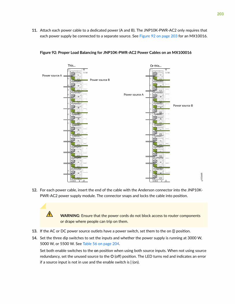
11. Attach each power cable to a dedicated power (A and B). The JNP10K-PWR-AC2 only requires thateach power supply be connected to a separate source. See Figure 92 on page 203 for an MX10016.
Figure 92: Proper Load Balancing for JNP10K-PWR-AC2 Power Cables on an MX100016
12. For each power cable, insert the end of the cable with the Anderson connector into the JNP10K-PWR-AC2 power supply module. The connector snaps and locks the cable into position.
WARNING: Ensure that the power cords do not block access to router componentsor drape where people can trip on them.
13. If the AC or DC power source outlets have a power switch, set them to the on (|) position.
14. Set the three dip switches to set the inputs and whether the power supply is running at 3000 W,5000 W, or 5500 W. See Table 56 on page 204.
Set both enable switches to the on position when using both source inputs. When not using sourceredundancy, set the unused source to the O (off) position. The LED turns red and indicates an errorif a source input is not in use and the enable switch is | (on).
203

Table 56: Setting the JNP10K-PWR-AC2 Dip Switches
Switch State Field
1 On IP0 is present
Off IP0 is not present
2 On IP1 is present
Off IP1 is not present
3 On Enabled for 30 A feed; 5500-W for a single feed, 5000-W for dualfeeds
Off Enabled for 20 A feed; power supply capacity is 3000-W
15. Verify that the INP1 and INP2 LEDs on the power supply faceplate are lit and are on steadily.
16. Press the power switch to the on (|) position.
How to Remove a JNP10K-PWR-DC Power Supply
Before you remove a DC power supply from the router:
• Ensure you understand how to prevent ESD damage (see "Prevention of Electrostatic DischargeDamage" on page 321).
Ensure that you have the following parts and tools available to remove a DC power supply:
• Electrostatic discharge (ESD) grounding strap
• Phillips (+) screwdriver, numbers 1 and 2
• 13/32 in. (10 mm) nut driver or socket wrench
• Replacement power supply or a cover panel for the power supply slot
The JNP10K-PWR-DC power supply in an MX10016 chassis is a hot-removable and hot-insertable field-replaceable unit (FRU). You remove DC power supplies from the rear of the chassis.
204
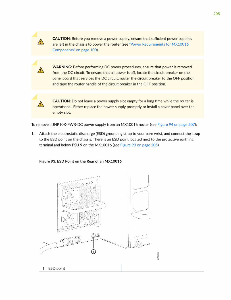
CAUTION: Before you remove a power supply, ensure that sufficient power suppliesare left in the chassis to power the router (see "Power Requirements for MX10016Components" on page 100).
WARNING: Before performing DC power procedures, ensure that power is removedfrom the DC circuit. To ensure that all power is off, locate the circuit breaker on thepanel board that services the DC circuit, router the circuit breaker to the OFF position,and tape the router handle of the circuit breaker in the OFF position.
CAUTION: Do not leave a power supply slot empty for a long time while the router isoperational. Either replace the power supply promptly or install a cover panel over theempty slot.
To remove a JNP10K-PWR-DC power supply from an MX10016 router (see Figure 94 on page 207):
1. Attach the electrostatic discharge (ESD) grounding strap to your bare wrist, and connect the strapto the ESD point on the chassis. There is an ESD point located next to the protective earthingterminal and below PSU 9 on the MX10016 (see Figure 93 on page 205).
Figure 93: ESD Point on the Rear of an MX10016
1— ESD point
205

2. Ensure that the voltage across the DC power source cable leads is 0 V, and that there is no chancethat the cable leads might become active during the removal process.
3. Ensure that the power supply output switch, to the right of the captive screw, is set to the standbyposition.
4. Unscrew the captive screw of the latch counterclockwise by using the number 1Phillips (+) screwdriver.
5. Rotate the captive screw away from the faceplate of the power supply to release the latch (seeFigure 94 on page 207).
6. Taking care not to touch the power supply components, pins, leads, or solder connections, placeone hand under the power supply to support it. Grasp the power supply handle with your otherhand, and pull the power supply completely out of the chassis.
CAUTION: See the heat symbol
. The power supply surfaces are hot. Allow a few minutes for the power supply tocool by pulling the power supply halfway out of the chassis, or wear heat-resistantgloves while removing the power supply.
7. If you are not replacing the power supply, install the cover panel over the slot.
a. Insert your thumb and forefinger into the finger holes of the cover panel.
b. Squeeze and place the cover panel in the slot and release your fingers and the cover remains inthe slot.
8. Remove the plastic cable cover that shields the DC power input terminal studs counterclockwise byusing the number 2 Phillips (+) screwdriver.
9. Unscrew the nuts counterclockwise from each DC power input terminal by using the 13/32 in.(10 mm) nut driver or socket wrench.
206

10. Remove the cable lugs from the DC power input terminal studs.
Figure 94: Removing a JNP10K-PWR-DC Power Supply from an MX10016
How to Install a JNP10K-PWR-DC Power Supply
Before you install a JNP10K-PWR-DC power supply in the chassis, ensure that you have followed allsafety warnings and cautions:
WARNING: Before performing DC power procedures, ensure that power is removedfrom the DC circuit. To ensure that all power is off, locate the circuit breaker on thepanel board that services the DC circuit, switch the circuit breaker to the OFF position,and secure the handle of the circuit breaker in the OFF position using tape.
CAUTION: Before you connect power to the router, a licensed electrician must attach acable lug to the grounding cable and power cables that you supply. A cable with anincorrectly attached lug can damage the router (for example, by causing a short circuit).
207

CAUTION: Do not mix AC and DC power supplies in the same chassis.
CAUTION: To meet safety and electromagnetic interference (EMI) requirements and toensure proper operation, you must connect MX10016 routers to earth ground beforeyou connect them to power. For installations that require a separate groundingconductor to the chassis, use the protective earthing terminal on the router chassis toconnect to earth ground. For instructions on connecting an MX10016 router to groundusing a separate grounding conductor, see "Connect an MX10016 to Earth Ground" onpage 159.
NOTE: Each battery return of the JNP10K-PWR-DC power supply must be connected as anisolated DC return (DC-I).
• Ensure you understand how to prevent ESD damage (see "Prevention of Electrostatic DischargeDamage" on page 321).
• Ensure that you have the following parts and tools available to install a JNP10K-PWR-DC powersupply:
• Electrostatic discharge (ESD) grounding strap
• DC power source cables (not provided) with the cable lugs (provided) attached
The provided terminal lugs in an MX10016 are sized for 4 AWG (21.1 mm2) power source cables.The DC power source cables that you provide must be 4 AWG (21.1 mm2), minimum 70° C wire.We recommend that you install heat-shrink tubing insulation around the crimped section of thepower cables and lugs.
NOTE: See the heat symbol
. Wear heat-resistant gloves while accessing the fan tray and power supply.
• 13/32 in. (10 mm) nut driver or socket wrench
208

• Phillips (+) screwdrivers, numbers 1 and 2
• Multimeter
You can install a power supply in any slot labeled PSU 0 through PSU 9 on an MX10016.
The JNP10K-PWR-DC power supply in an MX10016 chassis is a hot-removable and hot-insertable field-replaceable unit (FRU). You can install up to 10 JNP10K-PWR-DC power supplies in an MX10016 routerchassis. All DC power supplies install in the rear of the chassis in the slots along the left side of thechassis.
To install a JNP10K-PWR-DC power supply in an MX10016 (see Figure 99 on page 215):
1. Attach the electrostatic discharge (ESD) grounding strap to your bare wrist, and connect the strapto the ESD point on the chassis. There is an ESD point located next to the protective earthingterminal and below PSU 9 on the MX10016 rear panel (see Figure 95 on page 209).
Figure 95: ESD Point on the Rear of an MX10016 Chassis
1— ESD point
2. Taking care not to touch the power supply components, pins, leads, or solder connections, removethe power supply from its bag.
209
CAUTION: See the heat symbol
. The power supply surfaces are hot. Allow a few minutes for the power supply tocool by pulling the power supply halfway out of the chassis, or wear heat-resistantgloves while removing the power supply.
3. Peel back and remove the protective plastic wrap that covers all four sides of the power supply.
4. Ensure the power switch of the power supply is set to the standby (O) position. This switch turnsoff the output voltage; it does not interrupt DC power supply.
210

5. Remove the plastic cable cover from the DC power input terminals by using the number 2Phillips (+) screwdriver, to loosen the screws (see Figure 96 on page 211).
Figure 96: Removing the Plastic Cable Cover
6. Remove the nuts from each DC power supply input terminal, using the 13/32 in. (10 mm) nut driveror socket wrench to loosen the nuts.
7. Ensure that the power source circuit breaker is open so that the voltage across the DC powersource cable leads is 0 V, and that the cable leads do not become active while you are connectingDC power supply.
8. Verify that the DC power cables are correctly labeled before connecting them to the power supply.
In a typical power distribution scheme where the return is connected to chassis ground at thebattery plant, you can use a multimeter to verify the resistance of the –48V and RTN DC cables tochassis ground:
211

• The cable with very high resistance (indicating an open circuit) to chassis ground is negative (–)and must be connected to the –48V (input) DC power input terminal.
• The cable with very low resistance (indicating a closed circuit) to chassis ground is positive (+)and must be connected to the RTN (return) DC power input terminal.
CAUTION: You must ensure that power connections maintain the proper polarity.The power source cables might be labeled (+) and (–) to indicate their polarity.There is no standard color coding for DC power cables.
9. Install each power cable lug on the DC power input terminal, securing the lug with a nut (see Figure97 on page 213). Apply between 24 in.-lb (2.7 Nm) and 25 in.-lb (2.8 Nm) of torque to each nut.(Use the 13/32 in. [10 mm] nut driver or socket wrench.)
a. Secure each positive (+) DC source power cable lug to the RTN (return) DC power inputterminal.
212

b. Secure each negative (–) DC source power cable lug to the –48V (input) DC power inputterminal.
Figure 97: Connecting DC Power Supply Cables to an MX10016
Each power supply has two independent sets of DC power input terminals (INPUT 1: RTN –48V/–60V and INPUT 2: RTN –48V/–60V). For feed redundancy, each power supply must be powered bydedicated power feeds derived from feed INPUT 1 and feed INPUT 2. This configuration providesthe commonly deployed INPUT 1 / INPUT 2 feed redundancy for the router. There is basicinsulation between the inputs and the chassis ground, and also, there is basic insulation betweenthe RTN input feeds.
10. Install the plastic cable cover over each set of power cables by using the number 2Phillips (+) screwdriver, to tighten the screw.
213
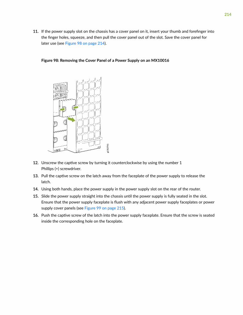
11. If the power supply slot on the chassis has a cover panel on it, insert your thumb and forefinger intothe finger holes, squeeze, and then pull the cover panel out of the slot. Save the cover panel forlater use (see Figure 98 on page 214).
Figure 98: Removing the Cover Panel of a Power Supply on an MX10016
12. Unscrew the captive screw by turning it counterclockwise by using the number 1Phillips (+) screwdriver.
13. Pull the captive screw on the latch away from the faceplate of the power supply to release thelatch.
14. Using both hands, place the power supply in the power supply slot on the rear of the router.
15. Slide the power supply straight into the chassis until the power supply is fully seated in the slot.Ensure that the power supply faceplate is flush with any adjacent power supply faceplates or powersupply cover panels (see Figure 99 on page 215).
16. Push the captive screw of the latch into the power supply faceplate. Ensure that the screw is seatedinside the corresponding hole on the faceplate.
214

17. Tighten the captive screw by turning it clockwise by using the number 1 Phillips (+) screwdriver.When the screw is completely tight, the latch locks into the router chassis.
Figure 99: Installing a JNP10K-PWR-DC Power Supply in an MX10016
WARNING: Ensure that the power cords do not block access to router componentsor drape where people can trip on them.
18. Set the enable switches for input 1 and input 2 (see Figure 100 on page 216).
Set both enable switches to the | (on) position when using both source inputs. When not usingsource redundancy, set the enable switch of the unused source to the O (off) position. The FAULT
215

LED on the power supply turns red to indicate an error if a source input is not in use and thecorresponding enable switch is set to the on (|) position.
Figure 100: Setting the Enable Switches for the Power Source
1— Enable switch for source input 1 2— Enable switch for source input 2
19. Verify that the input 1 and input 2 LEDs on the power supply faceplate are lit and are on steadily.
20. Set the power switch on the power supply to the on (|) position.
How to Remove a JNP10K-PWR-DC2 Power Supply
Before you remove a DC power supply from the router:
• Ensure you understand how to prevent ESD damage. See "Prevention of Electrostatic DischargeDamage" on page 321.
Ensure that you have the following parts and tools available to remove a DC power supply:
• Heat protective gloves able to withstand temperatures of 158°F (70°C)
• Electrostatic discharge (ESD) grounding strap
• Phillips (+) screwdriver, numbers 1 and 2
• 13/32 in. (10 mm) nut driver or socket wrench
• Replacement power supply or a cover panel for the power supply slot
216

The JNP10K-PWR-DC2 power supply in an MX10000 chassis is a hot-removable and hot-insertablefield-replaceable unit (FRU). You remove power supplies from the rear of the chassis.
CAUTION: A working JNP10K-PWR-DC2 power supply can reach temperatures of158°F (70°C); In order to avoid injury, do not touch a running power supply with yourbare hands.
CAUTION: Before you remove a power supply, ensure that you have power suppliessufficient to power the router left in the chassis. See"MX10016 Power Planning" onpage 100 and "Power Requirements for MX10016 Components" on page 100.
CAUTION: Do not leave the power supply slot empty for a long time while the router isoperational. Either replace the power supply promptly or install a cover panel over theempty slot.
To remove a JNP10K-PWR-DC2 power supply from an MX10016 router:
1. Attach the electrostatic discharge (ESD) grounding strap to your bare wrist, and connect the strapto the ESD point on the chassis. There is an ESD point located next to the protective earthingterminal and below PSU_9 on the MX10016 (see Figure 101 on page 217).
Figure 101: ESD Point on an MX10016 Chassis Rear
1— ESD point
2. Make sure that the voltage across the DC power source cables leads is 0 V and that there is nochance that the cables might become active during the removal process.
217
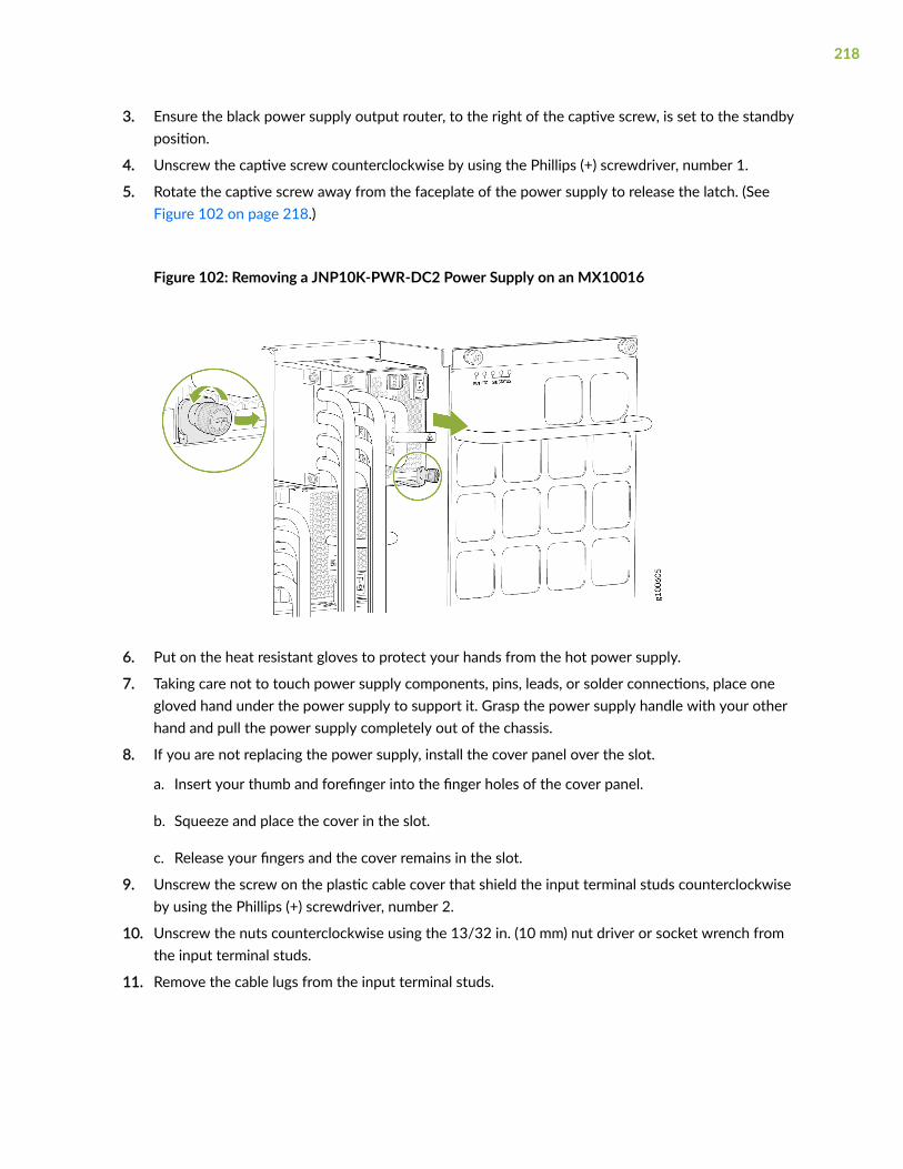
3. Ensure the black power supply output router, to the right of the captive screw, is set to the standbyposition.
4. Unscrew the captive screw counterclockwise by using the Phillips (+) screwdriver, number 1.
5. Rotate the captive screw away from the faceplate of the power supply to release the latch. (SeeFigure 102 on page 218.)
Figure 102: Removing a JNP10K-PWR-DC2 Power Supply on an MX10016
6. Put on the heat resistant gloves to protect your hands from the hot power supply.
7. Taking care not to touch power supply components, pins, leads, or solder connections, place onegloved hand under the power supply to support it. Grasp the power supply handle with your otherhand and pull the power supply completely out of the chassis.
8. If you are not replacing the power supply, install the cover panel over the slot.
a. Insert your thumb and forefinger into the finger holes of the cover panel.
b. Squeeze and place the cover in the slot.
c. Release your fingers and the cover remains in the slot.
9. Unscrew the screw on the plastic cable cover that shield the input terminal studs counterclockwiseby using the Phillips (+) screwdriver, number 2.
10. Unscrew the nuts counterclockwise using the 13/32 in. (10 mm) nut driver or socket wrench fromthe input terminal studs.
11. Remove the cable lugs from the input terminal studs.
218

How to Install a JNP10K-PWR-DC2 Power Supply
Before you install an HVDC power supply in the chassis, ensure that you have followed all safetywarnings and cautions:
WARNING: Before performing DC power procedures, ensure that power is removedfrom the DC circuit. To ensure that all power is off, locate the circuit breaker on thepanel board that services the DC circuit, router the circuit breaker to the OFF position,and tape the router handle of the circuit breaker in the OFF position.
WARNING: Protect yourself from severe burns by wearing heat-protective gloves whenremoving a working HVDC power supply from the chassis. HVDC power supplies canreach 158°F(70°C).
CAUTION: Before you connect power to the router, a licensed electrician must attach acable lug to the grounding and power cables that you supply. A cable with an incorrectlyattached lug can damage the router (for example, by causing a short circuit).
CAUTION: Do not mix AC, DC, or HVDC power supplies in the same running chassis.You can mix DC and HVDC power supplies while swapping out one type for anotherduring installation.
CAUTION: To meet safety and electromagnetic interference (EMI) requirements and toensure proper operation, you must connect MX10016 router to earth ground beforeyou connect them to power. For installations that require a separate groundingconductor to the chassis, use the protective earthing terminal on the router chassis toconnect to earth ground. For instructions on connecting an MX10016 router to groundusing a separate grounding conductor, see "Connect an MX10016 to Earth Ground" onpage 159.
NOTE: The battery returns of the JNP10K-PWR-DC2 power supply must be connected as anisolated DC return (DC-I).
• Ensure you understand how to prevent ESD damage. See "Prevention of Electrostatic DischargeDamage" on page 321.
219

• Ensure that you have the following parts and tools available to install a DC power supply:
• Electrostatic discharge (ESD) grounding strap
• Use high current cable assembly, CBL-PWR2-BARE (not provided) with the cable lugs (provided)attached
The provided terminal lugs for the JNP10K-PWR-DC2 are Panduit LCD4-14A-L, or equivalent,and sized for 4 AWG (21.1 mm2) power source cables. We recommend that you install heat-shrinktubing insulation around the crimped section of the power cables and lugs.
• 13/32 in. (10 mm) nut driver or socket wrench
• Phillips (+) screwdrivers, numbers 1 and 2
• Multimeter
The JNP10K-PWR-DC2 power supply in an MX10016 chassis is a hot-removable and hot-insertablefield-replaceable unit (FRU). You can install up to 10 power supplies in an MX10016 router chassis. AllHVDC power supplies install in the rear of the chassis in the slots along the left side of the chassis.
To install a JNP10K-PWR-DC2 power supply in an MX10016 :
1. Attach the electrostatic discharge (ESD) grounding strap to your bare wrist, and connect the strapto the ESD point on the chassis. There is an ESD point located next to the protective earthingterminal and below PSU_9 on the MX10016 (see Figure 103 on page 220).
Figure 103: ESD Point on an MX10016 Chassis Rear
1— ESD point
2. Taking care not to touch power supply components, pins, leads, or solder connections, remove thepower supply from its bag.
220
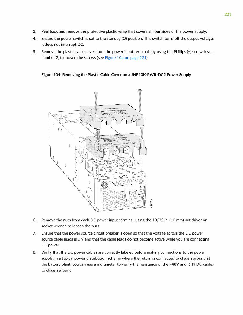
3. Peel back and remove the protective plastic wrap that covers all four sides of the power supply.
4. Ensure the power switch is set to the standby (O) position. This switch turns off the output voltage;it does not interrupt DC.
5. Remove the plastic cable cover from the power input terminals by using the Phillips (+) screwdriver,number 2, to loosen the screws (see Figure 104 on page 221).
Figure 104: Removing the Plastic Cable Cover on a JNP10K-PWR-DC2 Power Supply
6. Remove the nuts from each DC power input terminal, using the 13/32 in. (10 mm) nut driver orsocket wrench to loosen the nuts.
7. Ensure that the power source circuit breaker is open so that the voltage across the DC powersource cable leads is 0 V and that the cable leads do not become active while you are connectingDC power.
8. Verify that the DC power cables are correctly labeled before making connections to the powersupply. In a typical power distribution scheme where the return is connected to chassis ground atthe battery plant, you can use a multimeter to verify the resistance of the –48V and RTN DC cablesto chassis ground:
221

• The cable with very high resistance (indicating an open circuit) to chassis ground is negative (–)and will be installed on the –48V (input) DC power input terminal.
• The cable with very low resistance (indicating a closed circuit) to chassis ground is positive (+)and will be installed on the RTN (return) DC power input terminal.
CAUTION: You must ensure that power connections maintain the proper polarity.The power source cables might be labeled (+) and (–) to indicate their polarity.There is no standard color coding for DC power cables.
9. Install each power cable lug on the DC power input terminal, securing it with the nut (see Figure105 on page 223). Apply between 24 in.-lb (2.7 N-m) and 25 in.-lb (2.8 N-m) of torque to each nut.(Use the 13/32 in. [10 mm] nut driver or socket wrench.)
a. Secure each positive (+) DC source power cable lug to the RTN (return) DC power inputterminal.
b. Secure each negative (–) DC source power cable lug to the –48V (input) DC power inputterminal.
Each power supply has two independent sets of DC power input terminals (INPUT 1: RTN –48V/–60V: and INPUT 2: : RTN –48V/–60V). For feed redundancy, each power supply must be poweredby dedicated power feeds derived from feed INPUT 1 and feed INPUT 2. This configurationprovides the commonly deployed INPUT 1 / INPUT 2 feed redundancy for the router. There is basic
222
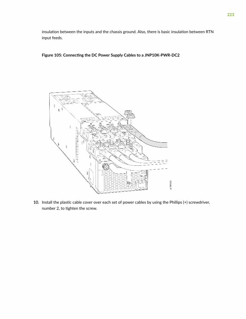
insulation between the inputs and the chassis ground. Also, there is basic insulation between RTNinput feeds.
Figure 105: Connecting the DC Power Supply Cables to a JNP10K-PWR-DC2
10. Install the plastic cable cover over each set of power cables by using the Phillips (+) screwdriver,number 2, to tighten the screw.
223

11. If the power supply slot on the chassis has a cover panel on it, insert your thumb and forefinger intothe finger holes, squeeze, and pull the cover out of the slot. Save the cover panel for later use (seeFigure 106 on page 224).
Figure 106: Removing the Power Supply Cover Panel on an MX10016
12. Unscrew the captive screw in the counterclockwise direction by using the Phillips (+) screwdriver,number 1.
13. Rotate the captive screw away from the faceplate of the power supply to release the latch.
14. Using both hands, place the power supply in the power supply slot on the rear of the router. Slidethe power supply straight into the chassis until the power supply is fully seated in the slot. Thepower supply will protrude from the chassis about 2 in. (5 cm) (see Figure 107 on page 225).
15. Push the captive screw into the power supply faceplate. Ensure that the screw is seated inside thecorresponding hole on the faceplate.
224
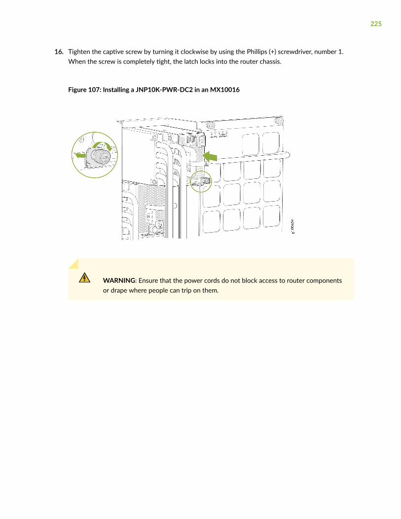
16. Tighten the captive screw by turning it clockwise by using the Phillips (+) screwdriver, number 1.When the screw is completely tight, the latch locks into the router chassis.
Figure 107: Installing a JNP10K-PWR-DC2 in an MX10016
WARNING: Ensure that the power cords do not block access to router componentsor drape where people can trip on them.
225
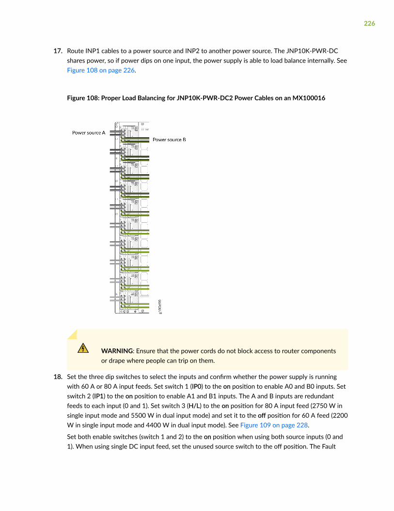
17. Route INP1 cables to a power source and INP2 to another power source. The JNP10K-PWR-DCshares power, so if power dips on one input, the power supply is able to load balance internally. SeeFigure 108 on page 226.
Figure 108: Proper Load Balancing for JNP10K-PWR-DC2 Power Cables on an MX100016
WARNING: Ensure that the power cords do not block access to router componentsor drape where people can trip on them.
18. Set the three dip switches to select the inputs and confirm whether the power supply is runningwith 60 A or 80 A input feeds. Set switch 1 (IP0) to the on position to enable A0 and B0 inputs. Setswitch 2 (IP1) to the on position to enable A1 and B1 inputs. The A and B inputs are redundantfeeds to each input (0 and 1). Set switch 3 (H/L) to the on position for 80 A input feed (2750 W insingle input mode and 5500 W in dual input mode) and set it to the off position for 60 A feed (2200W in single input mode and 4400 W in dual input mode). See Figure 109 on page 228.
Set both enable switches (switch 1 and 2) to the on position when using both source inputs (0 and1). When using single DC input feed, set the unused source switch to the off position. The Fault
226
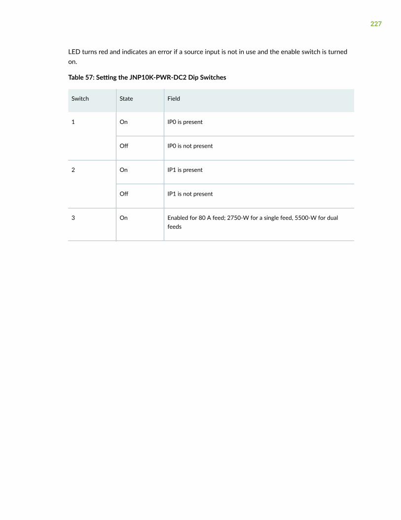
LED turns red and indicates an error if a source input is not in use and the enable switch is turnedon.
Table 57: Setting the JNP10K-PWR-DC2 Dip Switches
Switch State Field
1 On IP0 is present
Off IP0 is not present
2 On IP1 is present
Off IP1 is not present
3 On Enabled for 80 A feed; 2750-W for a single feed, 5500-W for dualfeeds
227
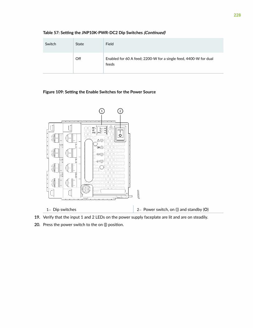
Table 57: Setting the JNP10K-PWR-DC2 Dip Switches (Continued)
Switch State Field
Off Enabled for 60 A feed; 2200-W for a single feed, 4400-W for dualfeeds
Figure 109: Setting the Enable Switches for the Power Source
1— Dip switches 2— Power switch, on (|) and standby (O)
19. Verify that the input 1 and 2 LEDs on the power supply faceplate are lit and are on steadily.
20. Press the power switch to the on (|) position.
228

Removing and Installing MX10016 Switch FabricBoards
IN THIS SECTION
How to Handle and Store an MX10016 Switch Fabric Board | 229
Removing an MX10016 Switch Fabric Board | 231
Installing an MX10016 Switch Fabric Board | 236
How to Handle and Store an MX10016 Switch Fabric Board
IN THIS SECTION
Handling Switch Fabric Boards | 230
Storing Switch Fabric Boards | 231
The MX10016 chassis has several field-replaceable units (FRUs) that have fragile components. To avoiddamaging the Switch Fabric Boards (SFBs), you must follow safe handling practices.
229
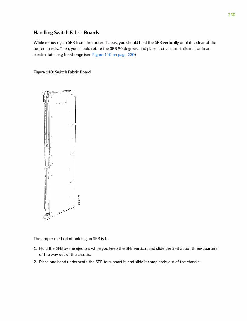
Handling Switch Fabric Boards
While removing an SFB from the router chassis, you should hold the SFB vertically until it is clear of therouter chassis. Then, you should rotate the SFB 90 degrees, and place it on an antistatic mat or in anelectrostatic bag for storage (see Figure 110 on page 230).
Figure 110: Switch Fabric Board
The proper method of holding an SFB is to:
1. Hold the SFB by the ejectors while you keep the SFB vertical, and slide the SFB about three-quartersof the way out of the chassis.
2. Place one hand underneath the SFB to support it, and slide it completely out of the chassis.
230

CAUTION: Never hold an SFB by the connector edge. The connectors are fragile. Youcannot align and seat an SFB properly if the connectors are damaged.
CAUTION: Do not stack SFBs on top of one another or on top of any othercomponent.
Storing Switch Fabric Boards
You must store SFBs either in the chassis or in a spare shipping container, horizontally and sheet-metalside down. Do not stack these units on top of one another or on top of any other component. Placeeach unit in an individual electrostatic bag or separately on an antistatic mat placed on a flat, stablesurface.
NOTE: Because these line cards are heavy, and because electrotatic bags are fragile, inserting aline card into the bag is best done by two people.
To insert an SFB into an electrostatic bag with the help of another person:
1. Hold the unit horizontally with the faceplate toward you.
2. Have the second person slide the opening of the electrostatic bag over the connector edge and thenpull the bag to cover the unit.
To insert an SFB into a bag by yourself:
1. Lay the unit horizontally on an antistatic mat that is on a flat, stable surface, with the sheet-metalside of the unit facing down.
2. Orient the unit with the faceplate toward you.
3. Carefully insert the connector edge into the opening of the bag, and then pull the bag toward you tocover the unit.
Removing an MX10016 Switch Fabric Board
An MX10016 has six Switch Fabric Boards (SFBs) that are located in the middle of the chassis behind thefan trays. SIB 0 through SIB 2 are located behind the left fan tray, and SIB 3 through SIB 5 are located
231

behind the right fan tray. You must remove the appropriate fan tray to access a failing SFB (see"Removing an MX10016 Fan Tray" on page 179).
Ensure you have the following equipment on hand before replacing an SFB:
• Electrostatic bag or antistatic mat
• Electrostatic discharge (ESD) grounding strap
To remove an SFB (see Figure 113 on page 235):
1. Set the fans to full speed by using the test chassis fan tray speed 0 full and test chassis fan tray speed 1full commands and wait for ten minutes.
2. Take the SFB offline using the request chassis sib slot slot number offline command.
NOTE: If you suspect the SFB is faulty and want to ensure that packets do not flow throughthe SFB, power down the SFB instead of taking the SFB offline. To power down the SFB, usethe set chassis sib power-off slot slot number command. To bring up a new SFB in the slot, youmust delete the old configuration using the delete chassis sib power-off slot slot numbercommand.
3. Place an electrostatic bag or an antistatic mat on a flat, stable surface.
4. Remove the appropriate fan tray (see "Removing an MX10016 Fan Tray" on page 179).
232
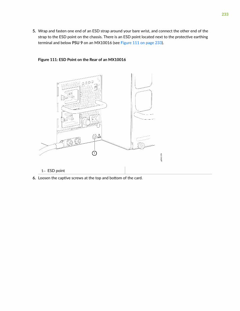
5. Wrap and fasten one end of an ESD strap around your bare wrist, and connect the other end of thestrap to the ESD point on the chassis. There is an ESD point located next to the protective earthingterminal and below PSU 9 on an MX10016 (see Figure 111 on page 233).
Figure 111: ESD Point on the Rear of an MX10016
1— ESD point
6. Loosen the captive screws at the top and bottom of the card.
233

7. Grasp both handles and and spread the handles apart, and then slide the SFB about a quarter of theway out of the slot (see Figure 112 on page 234).
Figure 112: Loosening Captive Screws and Spreading Ejector Handles of an SFB
8. Grasp the handle with one hand and place your other hand under the SFB for support as you slidethe SFB fully out of the slot (see Figure 113 on page 235).
234
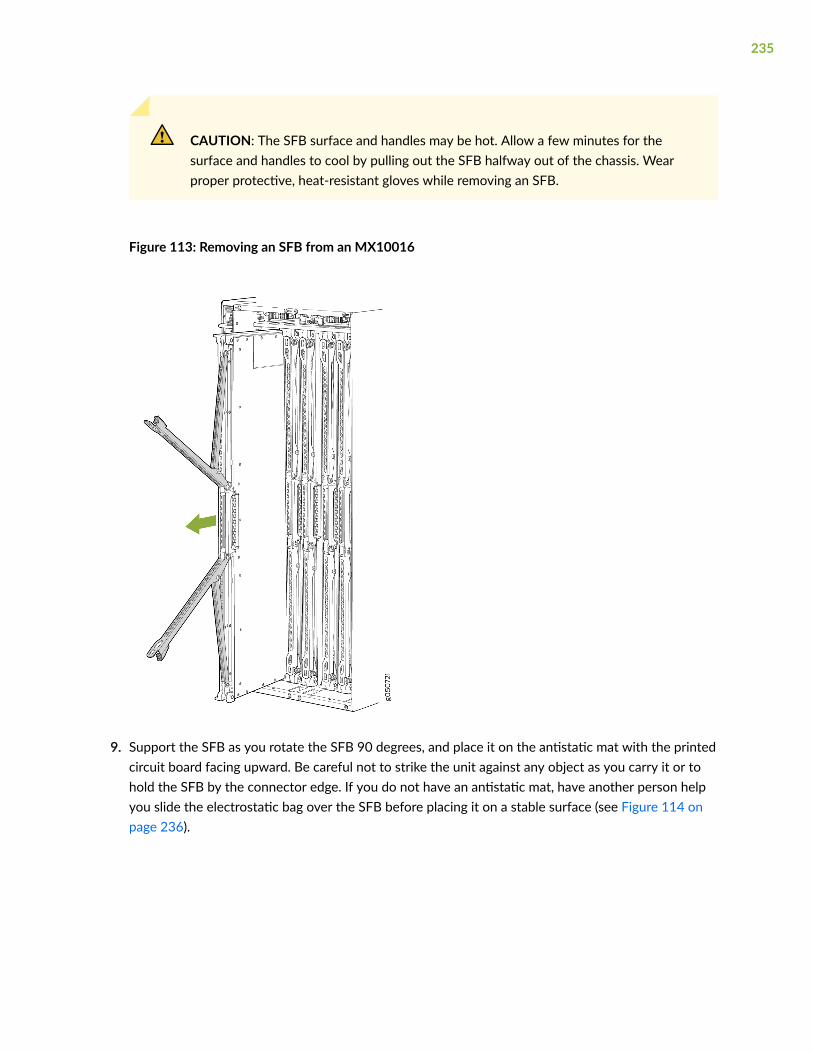
CAUTION: The SFB surface and handles may be hot. Allow a few minutes for thesurface and handles to cool by pulling out the SFB halfway out of the chassis. Wearproper protective, heat-resistant gloves while removing an SFB.
Figure 113: Removing an SFB from an MX10016
9. Support the SFB as you rotate the SFB 90 degrees, and place it on the antistatic mat with the printedcircuit board facing upward. Be careful not to strike the unit against any object as you carry it or tohold the SFB by the connector edge. If you do not have an antistatic mat, have another person helpyou slide the electrostatic bag over the SFB before placing it on a stable surface (see Figure 114 onpage 236).
235

CAUTION: Do not stack hardware components on top of one another after youremove them. Place each component separately on an antistatic mat that is placed on astable, flat surface.
Figure 114: An Extracted Switch Fabric Board
1— Connectors 2— Printed circuit board
Installing an MX10016 Switch Fabric Board
An MX10016router has six Switch Fabric Boards (SFBs) that are located in the middle of the chassisbehind the fan trays. SFB 0 through SFB 2 are located behind the left fan tray, and SFB 3 through SFB 5are located behind the right fan tray. You must remove the appropriate fan tray to install a SFB. SeeFigure 74 on page 181. Fan trays must be replaced within the duration mentioned in Table 58 on page236.
Table 58: Replacement Duration for the Fan Tray of an MX10016
Chassis Ambient Temperature Duration
27°C 3 minutes
35°C 2 minutes 46 seconds
40°C 2 minutes
236

NOTE: When replacing the fans or SIBs at 40°C chassis ambient temperature, ensure that thefans run at 100% fan speed for at least 10 minutes before replacing the fans or SIBs.
Use the test chassis fan tray 0 speed full-speed and test chassis fan tray 1 speed full-speedcommands to set the chassis fans to 100% speed.
Ensure you have the following equipment on hand before installing an SFB:
• Electrostatic bag or antistatic mat
• Electrostatic discharge (ESD) grounding strap
• Replacement SFB
To install an SFB:
1. Place an electrostatic bag or an antistatic mat on a flat, stable surface.
2. Wrap and fasten one end of an ESD strap around your bare wrist, and connect the other end of thestrap to the ESD point on the chassis. There is an ESD point located next to the protective earthingterminal and below PSU 9 on the MX10016 rear panel (see Figure 115 on page 237).
Figure 115: ESD Point on the Rear of an MX10016
1— ESD point
237
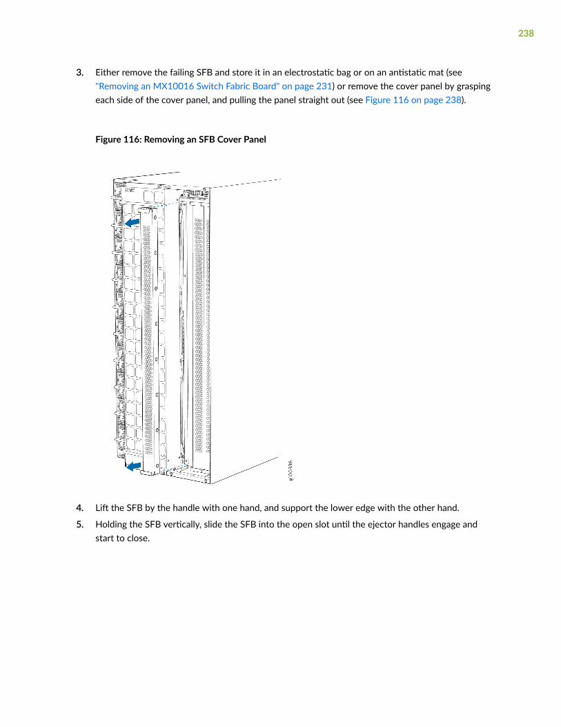
3. Either remove the failing SFB and store it in an electrostatic bag or on an antistatic mat (see"Removing an MX10016 Switch Fabric Board" on page 231) or remove the cover panel by graspingeach side of the cover panel, and pulling the panel straight out (see Figure 116 on page 238).
Figure 116: Removing an SFB Cover Panel
4. Lift the SFB by the handle with one hand, and support the lower edge with the other hand.
5. Holding the SFB vertically, slide the SFB into the open slot until the ejector handles engage andstart to close.
238

6. Grasp the two ejector handles and fold them inward until they latch so that the SFB is fully seated(see Figure 117 on page 239).
Figure 117: Installing an MX10016 SFB
7. Tighten the captive screws by using your thumb and forefinger.
8. Install the appropriate fan tray (see Figure 76 on page 184).
9. Set the fans to normal speed by using the test chassis fan tray speed 0 normal and test chassis fan trayspeed 1 normal command.
239

10. Bring the SFB online by using the request chassis sib slot slot numberonline command. You can checkthe status of the SFB by using the show chassis sfb and the show chassis fabric plane-locationcommands.
root> show chassis sfb
Slot State Uptime 0 Online 20 hours, 31 minutes, 24 seconds 1 Online 20 hours, 30 minutes, 40 seconds 2 Online 20 hours, 29 minutes, 55 seconds 3 Online 20 hours, 29 minutes, 8 seconds 4 Online 20 hours, 28 minutes, 14 seconds 5 Online 20 hours, 27 minutes, 20 seconds
root> show chassis fabric plane-location------------Fabric Plane Locations-------------Plane 0 Switch Fabric Board 0Plane 1 Switch Fabric Board 0Plane 2 Switch Fabric Board 0Plane 3 Switch Fabric Board 0Plane 4 Switch Fabric Board 1Plane 5 Switch Fabric Board 1Plane 6 Switch Fabric Board 1Plane 7 Switch Fabric Board 1Plane 8 Switch Fabric Board 2Plane 9 Switch Fabric Board 2Plane 10 Switch Fabric Board 2Plane 11 Switch Fabric Board 2Plane 12 Switch Fabric Board 3Plane 13 Switch Fabric Board 3Plane 14 Switch Fabric Board 3Plane 15 Switch Fabric Board 3Plane 16 Switch Fabric Board 4Plane 17 Switch Fabric Board 4Plane 18 Switch Fabric Board 4Plane 19 Switch Fabric Board 4Plane 20 Switch Fabric Board 5Plane 21 Switch Fabric Board 5Plane 22 Switch Fabric Board 5Plane 23 Switch Fabric Board 5
240

NOTE: If you completely powered off the SFB using the set chassis sib power-off slot slotcommand, you must delete the existing configuration in order to bring the SFB online. Todelete the existing configuration and bring a replacement SFB online, use the delete chassissib power-off slot slot number command.
Removing and Installing MX10016 MPCComponents
IN THIS SECTION
How to Handle and Store an MX10016 MPC | 241
Install an MPC in an MX10016 | 243
Remove an MPC | 247
Install the Cable Management System | 250
An MX10016 Modular Port Concentrator (MPC) is a field-replaceable unit (FRU) that you can install inany of the line card slots on the front of the chassis. An MPC is hot-insertable and hot-removable; youcan remove and replace them without powering off the router or disrupting router functions.
How to Handle and Store an MX10016 MPC
IN THIS SECTION
Handling MPCs | 242
Storing MPCs | 243
241

Handling MPCs
Pay proper attention to how you are handling MPCs. Because MPCs are installed horizontally, werecommend that you hold them by the sides of the units when they are not in the chassis. A runningMPC can be hot, use heat protective gloves, and allow the unit to cool half way out of the chassis beforeremoving.
To handle e an MPC properly:
1. Orient the MPC so that the faceplate of the unit is toward you.
2. Grasp each side of the unit firmly as you slide the unit out of the chassis.
3. Take care not to strike the unit against any object as you carry it.
CAUTION: Never hold an MPC by the connector edge. The connectors are fragile. Youcannot seat an MPC properly if the connectors are damaged (see Figure 118 on page242).
Figure 118: Connector Edge of an MPC
1— Connectors
4. If you must rest an MPC on an edge, place a cushion between the connector edge and the surface.
CAUTION: Do not stack MPCs on top of one another or on top of any othercomponent.
5. Place each MPC in an individual antistatic bag or separately on an antistatic mat that is placed on aflat, stable surface.
242

Storing MPCs
You must store MPCs either in the chassis or in a spare shipping container, horizontally and sheet-metalside down. Do not stack these units on top of one another or on top of any other component. Placeeach unit in an individual electrostatic bag or separately on an antistatic mat placed on a flat, stablesurface.
NOTE: Because these MPCs are heavy, and because antistatic bags are fragile, inserting an MPCinto the bag is best done by two people.
To insert an MPC into an antistatic bag with the help of another person:
1. Hold the unit horizontally with the faceplate toward you.
2. Have the second person slide the opening of the antistatic bag over the connector edge and thenpull the bag to cover the unit.
To insert an into a bag by yourself:
1. Lay the unit horizontally on an antistatic mat that is on a flat, stable surface, with the sheet-metalside of the unit facing down.
2. Orient the unit with the faceplate toward you.
3. Carefully insert the connector edge into the opening of the bag, and then pull the bag toward you tocover the unit.
Install an MPC in an MX10016
Before you install an MPC in the router chassis:
• Ensure that you have taken the necessary precautions to prevent electrostatic discharge (ESD)damage. See "Prevention of Electrostatic Discharge Damage" on page 321.
• Inspect the connector edge of the MPC for physical damage. Installing a damaged MPC mightdamage the router.
• Ensure that you know how to handle and store the line card (see
• Ensure that the router has sufficient power to power the line card while maintaining its n+1 powerredundancy. To determine whether the router has enough power available for the MPC, use the showchassis power-budget-statistics command.
243

• In addition to the MPC, ensure that you have the following parts and tools available to install an MPCin the router:
• ESD grounding strap
• An antistatic bag or an antistatic mat
To install an MPC in the router chassis:
1. Wrap and fasten one end of the ESD grounding strap around your bare wrist and connect the otherend of the strap to one of the ESD points on the chassis. An ESD point is located above the statusLED panel on the front of the router chassis. See Figure 119 on page 244.
Figure 119: ESD Point for MX10016 Chassis Front
1— ESD point
2. Remove the MPC cover by grasping the handles and pulling straight out to expose the slot for theMPC. See Figure 120 on page 244.
Figure 120: Remove the MPC Cover
244

3. Remove the MPC from the antistatic bag and place on the antistatic mat. Inspect it for any damagebefore installing it into the chassis.
CAUTION: Do not lift the MPC by holding the edge connectors or the handles on thefaceplate. Neither the handles nor the edge connectors can support the weight of theMPC. Lifting the MPC by the handles or edge connectors might bend them, whichwould prevent the line cards from being properly seated in the chassis. See Figure 121on page 245.
Figure 121: MPC Connectors
1— Connectors
4. With the faceplate towards you, grasp and lift the MPC by the sides. An MPC can weigh up to31.57 lb (14.32 kg). Be prepared to accept the full weight of the MPC as you lift the MPC.
245
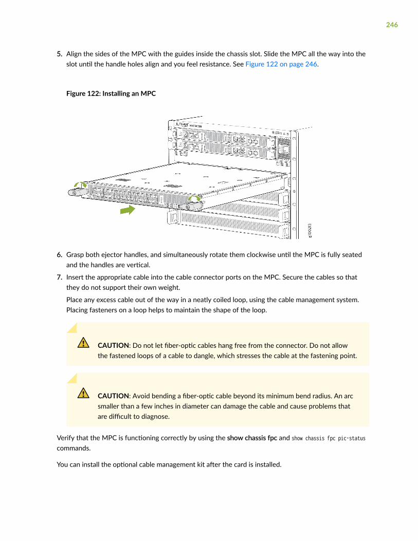
5. Align the sides of the MPC with the guides inside the chassis slot. Slide the MPC all the way into theslot until the handle holes align and you feel resistance. See Figure 122 on page 246.
Figure 122: Installing an MPC
6. Grasp both ejector handles, and simultaneously rotate them clockwise until the MPC is fully seatedand the handles are vertical.
7. Insert the appropriate cable into the cable connector ports on the MPC. Secure the cables so thatthey do not support their own weight.
Place any excess cable out of the way in a neatly coiled loop, using the cable management system.Placing fasteners on a loop helps to maintain the shape of the loop.
CAUTION: Do not let fiber-optic cables hang free from the connector. Do not allowthe fastened loops of a cable to dangle, which stresses the cable at the fastening point.
CAUTION: Avoid bending a fiber-optic cable beyond its minimum bend radius. An arcsmaller than a few inches in diameter can damage the cable and cause problems thatare difficult to diagnose.
Verify that the MPC is functioning correctly by using the show chassis fpc and show chassis fpc pic-statuscommands.
You can install the optional cable management kit after the card is installed.
246

Remove an MPC
If you have the optional cable management system, it is not necessary to remove the cable managementsystem before removing the MPC. However, we recommend that you take the MPCs offline beforeremoving them.
Before you remove an MPC from the router chassis:
• Ensure that you have taken the necessary precautions to prevent electrostatic discharge (ESD)damage (see "Prevention of Electrostatic Discharge Damage" on page 321).
• Ensure that you know how to handle and store the MPC (see "How to Handle and Store anMX10016 MPC" on page 241).
• Ensure that you have the following parts and tools available to remove an MPC from an MX10016chassis:
• ESD grounding strap
• An antistatic bag or an antistatic mat
NOTE: Placing an MPC in an antistatic bag might require a second person to assist withsliding the MPC into the bag.
• Replacement MPC or a cover for the empty slot
• Heat resistant gloves
When you remove an MPC, the router continues to function, although the interfaces that are installedon the MPC that is being removed no longer function.
To remove an MPC from an MX10016 router chassis:
1. Place the antistatic bag or antistatic mat on a flat, stable surface.
247
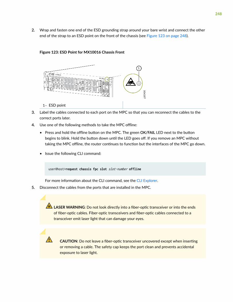
2. Wrap and fasten one end of the ESD grounding strap around your bare wrist and connect the otherend of the strap to an ESD point on the front of the chassis (see Figure 123 on page 248).
Figure 123: ESD Point for MX10016 Chassis Front
1— ESD point
3. Label the cables connected to each port on the MPC so that you can reconnect the cables to thecorrect ports later.
4. Use one of the following methods to take the MPC offline:
• Press and hold the offline button on the MPC. The green OK/FAIL LED next to the buttonbegins to blink. Hold the button down until the LED goes off. If you remove an MPC withouttaking the MPC offline, the router continues to function but the interfaces of the MPC go down.
• Issue the following CLI command:
user@host>request chassis fpc slot slot-number offline
For more information about the CLI command, see the CLI Explorer.
5. Disconnect the cables from the ports that are installed in the MPC.
LASER WARNING: Do not look directly into a fiber-optic transceiver or into the endsof fiber-optic cables. Fiber-optic transceivers and fiber-optic cables connected to atransceiver emit laser light that can damage your eyes.
CAUTION: Do not leave a fiber-optic transceiver uncovered except when insertingor removing a cable. The safety cap keeps the port clean and prevents accidentalexposure to laser light.
248

CAUTION: Avoid bending a fiber-optic cable beyond its minimum bend radius. Anarc smaller than a few inches in diameter can damage the cable and cause problemsthat are difficult to diagnose.
6. Arrange the disconnected cables in the cable manager to prevent the cables from developing stresspoints.
7. Simultaneously turn both the handles of the MPC counterclockwise to unseat the MPC. See Figure124 on page 249.
Figure 124: Removing an MPC
8. Put on the heat resistant gloves.
9. Grasp the handles, and holding the MPC straight, slide it halfway out of the card slot.
CAUTION: The MPC and the handles might be hot. Allow a few minutes for theMPC and handles to cool before removing the MPC from the chassis.
10. Grasp both sides of the MPC at the midpoint, and remove the MPC from the chassis. Slide the MPCcompletely out of the chassis, and place the MPC on the antistatic mat or in the antistatic bag.
249

CAUTION: The weight of the MPC is concentrated in the back end. Be prepared toaccept the full weight of the MPC—up to 31.57 lb. (14.32 kg)—as you slide the MPCout of the chassis.
When the MPC is out of the chassis, do not hold it by the ejector handles, bus bars,or edge connectors. They cannot support the weight of the MPC.
Do not stack MPCs on top of one another after removal. Place each MPCindividually in an antistatic bag or on its own antistatic mat on a flat, stable surface.
11. If you are not installing another MPC into the empty card slot within a short time, install an MPCcover over the slot to maintain proper airflow in the chassis.
CAUTION: After removing an MPC from the chassis, wait at least 30 secondsbefore replacing it with another MPC, or inserting an MPC into a different slot.
Install the Cable Management System
The cable management system is an optional kit that can be ordered to organize and protect opticalcabling attached to the line cards. After a card is installed, you can still remove the line card withoutneeding to remove the cable management system.
Ensure that you have the following parts and tools available to install the cable management system on aline card:
• Phillips (+) screwdriver, number 2
• The cable management system
To install the cable management system (see Figure 125 on page 251):
1. Open the shipping carton of the cable management system and check that you have:
• Two handle extensions
250
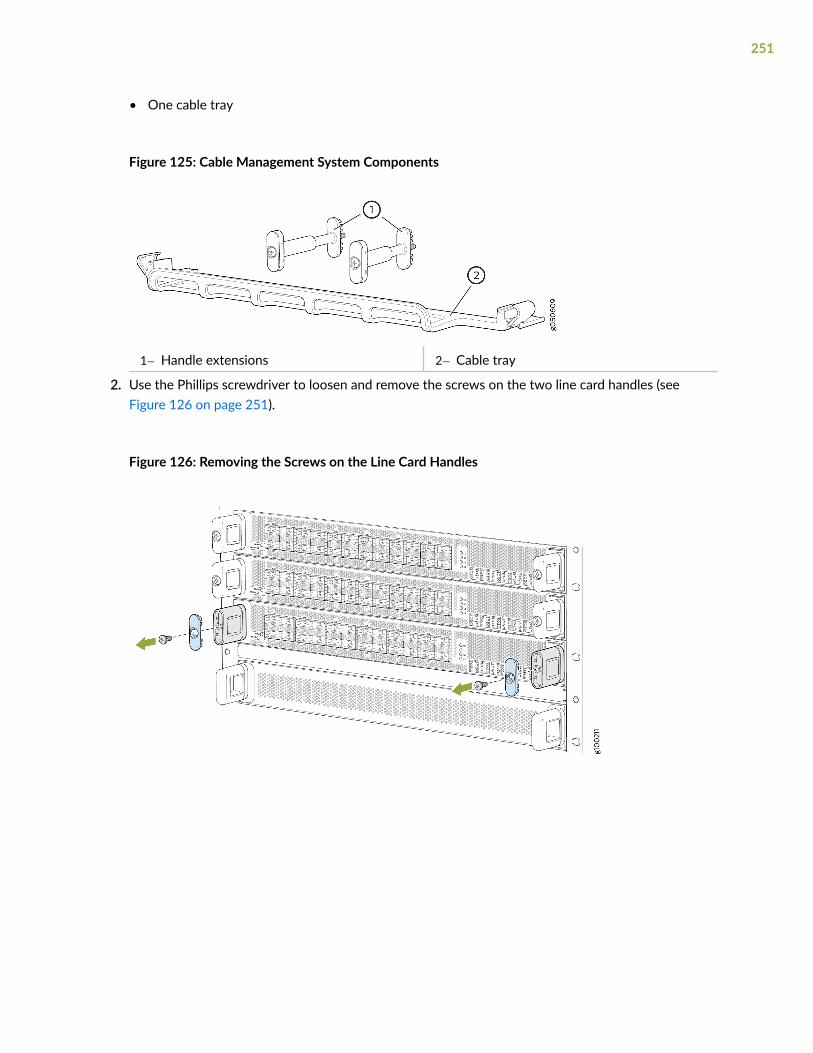
• One cable tray
Figure 125: Cable Management System Components
1— Handle extensions 2— Cable tray
2. Use the Phillips screwdriver to loosen and remove the screws on the two line card handles (seeFigure 126 on page 251).
Figure 126: Removing the Screws on the Line Card Handles
251

3. Replace the blue cap on each line card handle with the two handle extensions (see Figure 127 onpage 252).
Figure 127: Adding Handle Extensions
4. Tighten the screws into the handle extensions.
5. Snap open the blue clips on the ends of the cable tray with your hands.
6. Place the cable tray across the front of the line card so that the two ends of the cable tray are underthe handle extensions.
252

7. Snap close the blue clips of the cable tray around the handle extensions (see Figure 128 on page253).
Figure 128: Adding the Cable Tray
8. Drape the optical cables using one of the following methods:
• Drape and tie the optical cables to the side (see Figure 129 on page 254).
253

• Drape some of the cables under the handle extension and some cables over the handle extension.
Figure 129: Completed Cable Management System
RELATED DOCUMENTATION
MX10016 Optional Equipment | 30
Removing and Installing Transceivers and Fiber-Optic Cables
IN THIS SECTION
Remove a Transceiver | 255
Install a Transceiver | 257
254
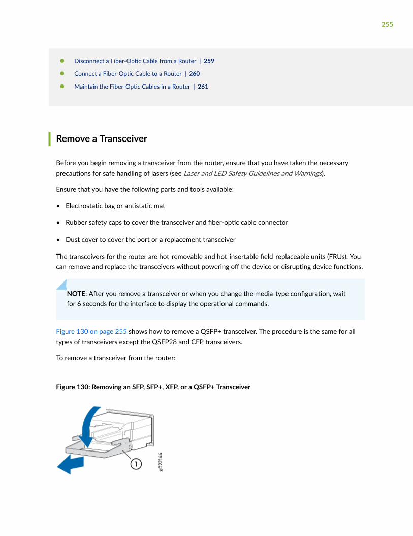
Disconnect a Fiber-Optic Cable from a Router | 259
Connect a Fiber-Optic Cable to a Router | 260
Maintain the Fiber-Optic Cables in a Router | 261
Remove a Transceiver
Before you begin removing a transceiver from the router, ensure that you have taken the necessaryprecautions for safe handling of lasers (see Laser and LED Safety Guidelines and Warnings).
Ensure that you have the following parts and tools available:
• Electrostatic bag or antistatic mat
• Rubber safety caps to cover the transceiver and fiber-optic cable connector
• Dust cover to cover the port or a replacement transceiver
The transceivers for the router are hot-removable and hot-insertable field-replaceable units (FRUs). Youcan remove and replace the transceivers without powering off the device or disrupting device functions.
NOTE: After you remove a transceiver or when you change the media-type configuration, waitfor 6 seconds for the interface to display the operational commands.
Figure 130 on page 255 shows how to remove a QSFP+ transceiver. The procedure is the same for alltypes of transceivers except the QSFP28 and CFP transceivers.
To remove a transceiver from the router:
Figure 130: Removing an SFP, SFP+, XFP, or a QSFP+ Transceiver
255
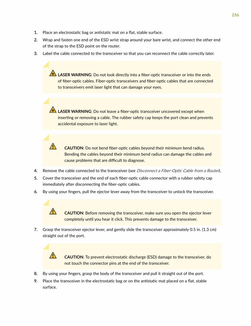
1. Place an electrostatic bag or antistatic mat on a flat, stable surface.
2. Wrap and fasten one end of the ESD wrist strap around your bare wrist, and connect the other endof the strap to the ESD point on the router.
3. Label the cable connected to the transceiver so that you can reconnect the cable correctly later.
LASER WARNING: Do not look directly into a fiber-optic transceiver or into the endsof fiber-optic cables. Fiber-optic transceivers and fiber-optic cables that are connectedto transceivers emit laser light that can damage your eyes.
LASER WARNING: Do not leave a fiber-optic transceiver uncovered except wheninserting or removing a cable. The rubber safety cap keeps the port clean and preventsaccidental exposure to laser light.
CAUTION: Do not bend fiber-optic cables beyond their minimum bend radius.Bending the cables beyond their minimum bend radius can damage the cables andcause problems that are difficult to diagnose.
4. Remove the cable connected to the transceiver (see Disconnect a Fiber-Optic Cable from a Router).
5. Cover the transceiver and the end of each fiber-optic cable connector with a rubber safety capimmediately after disconnecting the fiber-optic cables.
6. By using your fingers, pull the ejector lever away from the transceiver to unlock the transceiver.
CAUTION: Before removing the transceiver, make sure you open the ejector levercompletely until you hear it click. This prevents damage to the transceiver.
7. Grasp the transceiver ejector lever, and gently slide the transceiver approximately 0.5 in. (1.3 cm)straight out of the port.
CAUTION: To prevent electrostatic discharge (ESD) damage to the transceiver, donot touch the connector pins at the end of the transceiver.
8. By using your fingers, grasp the body of the transceiver and pull it straight out of the port.
9. Place the transceiver in the electrostatic bag or on the antistatic mat placed on a flat, stablesurface.
256
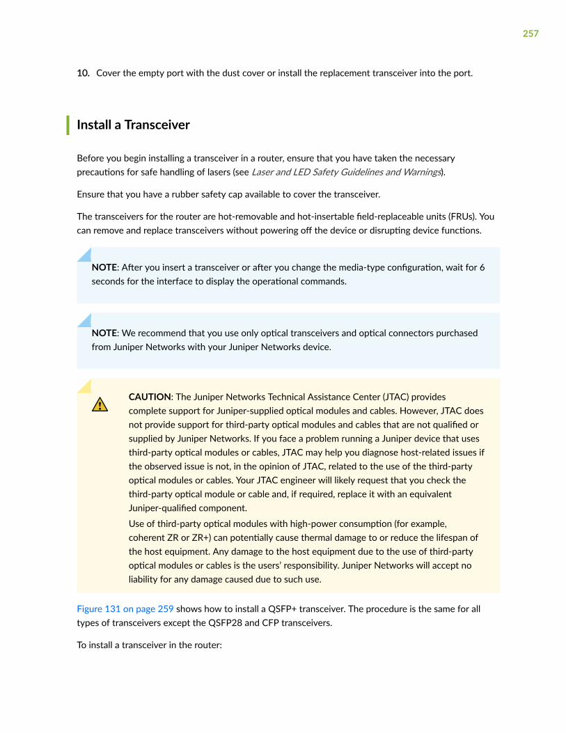
10. Cover the empty port with the dust cover or install the replacement transceiver into the port.
Install a Transceiver
Before you begin installing a transceiver in a router, ensure that you have taken the necessaryprecautions for safe handling of lasers (see Laser and LED Safety Guidelines and Warnings).
Ensure that you have a rubber safety cap available to cover the transceiver.
The transceivers for the router are hot-removable and hot-insertable field-replaceable units (FRUs). Youcan remove and replace transceivers without powering off the device or disrupting device functions.
NOTE: After you insert a transceiver or after you change the media-type configuration, wait for 6seconds for the interface to display the operational commands.
NOTE: We recommend that you use only optical transceivers and optical connectors purchasedfrom Juniper Networks with your Juniper Networks device.
CAUTION: The Juniper Networks Technical Assistance Center (JTAC) providescomplete support for Juniper-supplied optical modules and cables. However, JTAC doesnot provide support for third-party optical modules and cables that are not qualified orsupplied by Juniper Networks. If you face a problem running a Juniper device that usesthird-party optical modules or cables, JTAC may help you diagnose host-related issues ifthe observed issue is not, in the opinion of JTAC, related to the use of the third-partyoptical modules or cables. Your JTAC engineer will likely request that you check thethird-party optical module or cable and, if required, replace it with an equivalentJuniper-qualified component.
Use of third-party optical modules with high-power consumption (for example,coherent ZR or ZR+) can potentially cause thermal damage to or reduce the lifespan ofthe host equipment. Any damage to the host equipment due to the use of third-partyoptical modules or cables is the users’ responsibility. Juniper Networks will accept noliability for any damage caused due to such use.
Figure 131 on page 259 shows how to install a QSFP+ transceiver. The procedure is the same for alltypes of transceivers except the QSFP28 and CFP transceivers.
To install a transceiver in the router:
257

CAUTION: To avoid electrostatic discharge (ESD) damage to the transceiver, do nottouch the connector pins at the end of the transceiver.
1. Wrap and fasten one end of the ESD wrist strap around your bare wrist, and connect the other endof the strap to the ESD point on the router.
2. Remove the transceiver from its bag.
3. Check whether the transceiver is covered with a rubber safety cap. If it is not, cover the transceiverwith a rubber safety cap.
LASER WARNING: Do not leave a fiber-optic transceiver uncovered except when insertingor removing a cable. The rubber safety cap keeps the port clean and prevents accidentalexposure to laser light.
4. If the port in which you want to install the transceiver is covered with a dust cover, remove the dustcover, and save the cover in case you need to cover the port later. If you are hot-swapping atransceiver, wait for at least 10 seconds after removing the transceiver from the port before installinga new transceiver.
5. Using both hands, carefully place the transceiver in the empty port. The connectors must face thedevice chassis.
CAUTION: Before you slide the transceiver into the port, ensure that the transceiver isaligned correctly. Misalignment of the transceiver might cause the pins to bend, makingthe transceiver unusable.
6. Slide the transceiver in gently until it is fully seated. See Figure 131 on page 259 for an example ofinserting a QSFP transceiver.
7. Remove the rubber safety cap when you are ready to connect the cable to the transceiver.
258

LASER WARNING: Do not look directly into a fiber-optic transceiver or into the ends offiber-optic cables. Fiber-optic transceivers and fiber-optic cables that are connected totransceivers emit laser light that can damage your eyes.
Figure 131: Installing a Transceiver
1— Ejector lever
Disconnect a Fiber-Optic Cable from a Router
Before you disconnect a fiber-optic cable from an optical transceiver installed in the router, ensure thatyou have taken the necessary precautions for safe handling of lasers (see Laser and LED SafetyGuidelines and Warnings).
Ensure that you have the following parts and tools available:
• Rubber safety cap to cover the transceiver
• Rubber safety cap to cover the fiber-optic cable connector
The router has field-replaceable optical transceivers to which you can connect fiber-optic cables.
To disconnect a fiber-optic cable from an optical transceiver installed in the router:
1. (Recommended) Disable the port in which the transceiver is installed by using the disable statementat the [edit interfaces] hierarchy level for the specific interface.
259

LASER WARNING: Do not look directly into a fiber-optic transceiver or into the ends offiber-optic cables. Fiber-optic transceivers and fiber-optic cables connected to transceiversemit laser light that can damage your eyes.
LASER WARNING: Do not stare into the laser beam emitted by an interface or view itdirectly with optical instruments even if the interface has been disabled.
2. Carefully unplug the fiber-optic cable connector from the transceiver.
3. Cover the transceiver with a rubber safety cap.
LASER WARNING: Do not leave a fiber-optic transceiver uncovered except when insertingor removing a cable. The rubber safety cap keeps the port clean and prevents accidentalexposure to laser light.
4. Cover the fiber-optic cable connector with the rubber safety cap.
Connect a Fiber-Optic Cable to a Router
Before you connect a fiber-optic cable to an optical transceiver installed in the router, ensure that youhave taken the necessary precautions for safe handling of lasers (see Laser and LED Safety Guidelinesand Warnings).
The router has field-replaceable unit (FRU) optical transceivers to which you can connect fiber-opticcables. You can remove and replace the cables without powering off the device or disrupting the routingfunctions.
To connect a fiber-optic cable to an optical transceiver installed in the router:
LASER WARNING: Do not look directly into a fiber-optic transceiver or into the ends offiber-optic cables. Fiber-optic transceivers and fiber-optic cables connected to transceiversemit laser light that can damage your eyes.
LASER WARNING: Do not stare into the laser beam emitted by an interface or view itdirectly with optical instruments even if the interface has been disabled.
260

1. If the fiber-optic cable connector is covered by a rubber safety cap, remove the cap. Save the cap.
2. If the optical transceiver is covered by a rubber safety cap, remove the cap. Save the cap.
3. Insert the cable connector into the optical transceiver.
4. Secure the cables so that they are not supporting their own weight. Place excess cable out of theway in a neatly coiled loop. Placing fasteners on a loop helps cables maintain their shape.
CAUTION: Do not bend fiber-optic cables beyond their minimum bend radius. Bendingthe cables beyond their minimum bend radius can damage the cables and causeproblems that are difficult to diagnose.
CAUTION: Do not let fiber-optic cables hang free from the connector. Do not allowfastened loops of cables to dangle, which stresses the cables at the fastening point.
Maintain the Fiber-Optic Cables in a Router
To maintain fiber-optic cables:
• When you unplug a fiber-optic cable from a transceiver, place rubber safety caps over the transceiverand on the end of the cable.
• Anchor fiber-optic cable to avoid stress on the connectors. When attaching a fiber-optic cable to atransceiver, be sure to secure the fiber-optic cable so that the cable is not supporting its own weightas it hangs to the floor. Never let a fiber-optic cable hang free from the connector.
• Do not bend fiber-optic cables beyond their minimum bend radius. Bending the cables beyond theirminimum bend radius can damage the cables and cause problems that are difficult to diagnose.
• Frequent plugging and unplugging of fiber-optic cables in and out of optical instruments can damagethe instruments, which are expensive to repair. Attach a short fiber extension to the opticalequipment. Any wear and tear due to frequent plugging and unplugging is then absorbed by theshort fiber extension, which is easier and less expensive to replace than the instruments.
• Keep fiber-optic cable connections clean. Microscopic deposits of oil and dust in the canal of thetransceiver or cable connector can cause loss of light, reduction in signal power, and possiblyintermittent problems with the optical connection.
To clean the transceiver canal, use an appropriate fiber-cleaning device such as RIFOCS Fiber OpticAdaptor Cleaning Wands (part number 946). Follow the directions in the cleaning kit you use.
261
After cleaning the transceiver, make sure that the connector tip of the fiber-optic cable is clean. Useonly an approved alcohol-free fiber-optic cable cleaning kit such as the Cletop-S® Fiber Cleaner.Follow the directions in the cleaning kit you use.
Removing an MX10016 Router
IN THIS SECTION
Powering Off an MX10016 Router | 262
Removing an MX10016 Router From a Four-Post Rack Using a Mechanical Lift | 265
Before you remove an MX10016, you must first poweroff the router, and then follow the procedure toremove the router from the rack.
Powering Off an MX10016 Router
Before you power off an MX10016:
• Ensure that you have taken the necessary precautions to prevent electrostatic discharge (ESD)damage see "Prevention of Electrostatic Discharge Damage" on page 321).
• Ensure that you do not need to forward traffic through the router.
Ensure that you have the following parts and tools available to power off the router:
• An ESD grounding strap
• An external management device such as a PC
• An RJ-45 to DB-9 rollover cable to connect the external management device to the console port onone of the RCBs
To power off an MX10016:
1. Connect to the router using one of the following methods:
262

• Connect a management device to the console (CON) port on an RCB by following the instructionsin "Connecting an MX10016 Router to a Management Console" on page 164.
• Connect a management device to one of the two management (MGMT) ports on the RCB byfollowing the instructions in "Connecting an MX10016 to a Network for Out-of-BandManagement" on page 163.
2. Shut down Junos OS from the external management device by using the request vmhost haltoperational mode CLI command.
This command shuts down the router gracefully and preserves system state information. A messageappears on the console, confirming that the operating system has halted.
You see the following output (or something similar, depending on the hardware being shut down)after entering the command:
Shutdown NOW!System going down IMMEDIATELY
TerminatedPoweroff for hypervisor to respawnOct 25 10:35:05 init: event-processing (PID 1114) exited with status=1Oct 25 10:35:05 init: packet-forwarding-engine (PID 1424) exited with status=8.Waiting (max 60 seconds) for system process `vnlru_mem' to stop...doneWaiting (max 60 seconds) for system process `vnlru' to stop...doneWaiting (max 60 seconds) for system process `bufdaemon' to stop...doneWaiting (max 60 seconds) for system process `syncer' to stop...Syncing disks, vnodes remaining...0 0 0 0 done
syncing disks... All buffers synced.Uptime: 11h0m30sNormal shutdown (no dump device defined)unloading fpga driverunloading fx-scpldPowering system off using ACPIkvm: 28646: cpu0 disabled perfctr wrmsr: 0xc1 data 0xabcdpci-stub 0000:01:00.2: transaction is not cleared; proceeding with reset anywaypci-stub 0000:01:00.1: transaction is not cleared; proceeding with reset anywayhub 1-1:1.0: over-current change on port 1Stopping crond: [ OK ]Stopping libvirtd daemon: [ OK ]Shutting down ntpd: [ OK ]
263
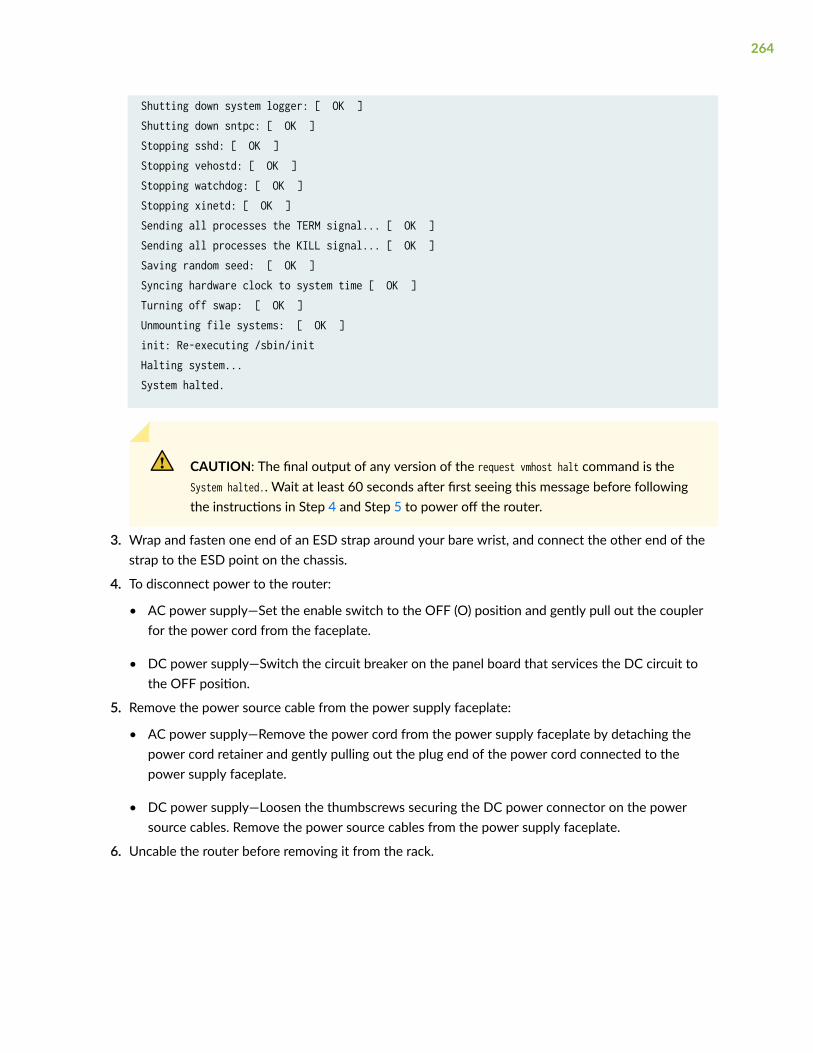
Shutting down system logger: [ OK ]Shutting down sntpc: [ OK ]Stopping sshd: [ OK ]Stopping vehostd: [ OK ]Stopping watchdog: [ OK ]Stopping xinetd: [ OK ]Sending all processes the TERM signal... [ OK ]Sending all processes the KILL signal... [ OK ]Saving random seed: [ OK ]Syncing hardware clock to system time [ OK ]Turning off swap: [ OK ]Unmounting file systems: [ OK ]init: Re-executing /sbin/initHalting system...System halted.
CAUTION: The final output of any version of the request vmhost halt command is theSystem halted.. Wait at least 60 seconds after first seeing this message before followingthe instructions in Step 4 and Step 5 to power off the router.
3. Wrap and fasten one end of an ESD strap around your bare wrist, and connect the other end of thestrap to the ESD point on the chassis.
4. To disconnect power to the router:
• AC power supply—Set the enable switch to the OFF (O) position and gently pull out the couplerfor the power cord from the faceplate.
• DC power supply—Switch the circuit breaker on the panel board that services the DC circuit tothe OFF position.
5. Remove the power source cable from the power supply faceplate:
• AC power supply—Remove the power cord from the power supply faceplate by detaching thepower cord retainer and gently pulling out the plug end of the power cord connected to thepower supply faceplate.
• DC power supply—Loosen the thumbscrews securing the DC power connector on the powersource cables. Remove the power source cables from the power supply faceplate.
6. Uncable the router before removing it from the rack.
264

Removing an MX10016 Router From a Four-Post Rack Using aMechanical Lift
Before you remove the router using a lift:
• Ensure that the rack is stable and secured to the building.
• Ensure there is enough space to place the uninstalled router in its new location and along the path tothe new location (see "Depth Clearance Requirements for Airflow and Hardware Maintenance for anMX10016" on page 98).
• Review "General Safety Guidelines and Warnings" on page 296.
• Review the chassis lifting guidelines described in "MX10016 Chassis Lifting Guidelines" on page 302.
• Ensure that the router has been safely powered off (see "Powering Off an MX10016 Router" on page262).
CAUTION: When removing more than one router chassis from a rack, remove therouters in order from top to bottom.
Ensure that you have the following parts and tools available to remove the router:
• A mechanical lift rated for 500 lbs. (226.8 kg)
• A Phillips (+) screwdriver, number 2 or number 3, depending on the size of your rack-mountingscrews
Because of the size and weight of the router, we strongly recommend using a mechanical lift to removethe MX10016.
To removethe router using a mechanical lift (see Figure 132 on page 266):
1. Use the appropriate Phillips (+) screwdriver to remove the 14 mounting screws that attach thechassis flange to the rack.
2. Move the lift to the rack and position the lift so that its platform is centered about 0.5 in. (1.27 cm)below the bottom of the router chassis and as close to the chassis as possible.
3. Carefully slide the router from the adjustable base brackets attached to the rack onto the lift.
4. Move the lift away from the rack and lower the lift.
265

5. Use the lift to transport the router to its new location.
Figure 132: Moving the MX10016 Using a Mechanical Lift
266

5CHAPTER
Troubleshooting Hardware
Restoring Junos OS | 268
Alarm Messages | 272

Restoring Junos OS
IN THIS SECTION
Creating an Emergency Boot Device | 268
Performing a Recovery Installation Using an Emergency Boot Device | 270
Creating an Emergency Boot Device
Before you begin, you need to download the installation media image for your device and Junos OSrelease from https://www.juniper.net/customers/support/ .
If Junos OS on the device is damaged in some way that prevents the software from loading properly, youcan use an emergency boot device to repartition the primary disk and load a fresh installation of JunosOS. Use the following procedure to create an emergency boot device.
NOTE: You can create the emergency boot device on another Juniper Networks router or router,or any PC or laptop that supports Linux. The steps you take to create the emergency boot devicevary, depending on the device.
To create an emergency boot device:
1. Use FTP to copy the installation media image into the /var/tmp directory on the device.
2. Insert a USB device into the USB port.
3. From the Junos OS command-line interface (CLI), start the shell:
user@device> start shell%
4. Switch to the root account using the su command:
% suPassword: password
268

NOTE: The password is the root password for the device. If you logged in to the device asroot, you do not need to perform this step.
5. Enter the following command on the device:
root@device% dd if=/var/tmp/filename of=/dev/da1 bs=16k
The device writes the installation media image to the USB device:
root@device% dd if=install-media-qfx-5e-15.1X53-D30.5-domestic.img of=/dev/da0 bs=1m1399+0 records in1399+0 records out1466957824 bytes transferred in 394.081902 secs (3722469 bytes/sec)
6. Enter the following command:
root@device% dd if=/var/tmp/filename of=/dev/da0 bs=1048576
The device writes the installation media image to the USB device:
root@device% dd if=/var/tmp/jinstall-vjunos-usb-13.2.img of=/dev/da0 bs=104857611006+1 records in11006+1 records out180332544 bytes transferred in 71.764266 secs (2512846 bytes/sec)
NOTE: The device automatically create a recovery Junos OS image.
The “Select a recovery image” menu appears on the console when one of these routers isbooted and unable to load a version of Junos OS. You can follow the instructions in the“Select a recovery image” menu to load the Junos OS image for one of these routers.
7. Log out of the shell:
root@device% exit% exituser@device>
269

Performing a Recovery Installation Using an Emergency Boot Device
If Junos OS on your device is damaged in some way that prevents the software from loading correctly,you might need to perform a recovery installation using an emergency boot device (for example, a USBflash drive) to restore the default factory installation. After you have recovered the software, you needto restore the device configuration. You can either create a new configuration as you did when thedevice was shipped from the factory, or if you saved the previous configuration, you can simply restorethat file to the device.
We recommend that you perform the following steps before you perform the recovery installation:
1. Ensure that you have an emergency boot device to use during the installation. See Creating anEmergency Boot Device for information about how to create an emergency boot device.
2. Copy the existing configuration in the file /config/juniper.conf.gz from the device to a remotesystem, such as a server, or to an emergency boot device. For extra safety, you can also copy thebackup configurations (the files named /config/juniper.conf.n, where n is a number from 0 through 9)to a remote system or to an emergency boot device.
You can use the system snapshot feature to complete this step. The system snapshot feature takes a“snapshot” of the files currently used to run the MX10008 router—the complete contents of the /config and /var directories, which include the running Juniper Networks Junos OS, the activeconfiguration, and the rescue configuration—and copies all of these files into a memory source.
WARNING: The recovery installation process completely overwrites the entirecontents of the internal flash storage.
3. Copy any other stored files to a remote system as desired.
To reinstall Junos OS:
1. Insert the emergency boot device into the router.
2. Power cycle the router.
The emergency boot device is detected. At this time, you can load Junos OS from the emergencyboot device onto the internal flash storage.
3. Install Junos OS by choosing one of the following options:
270

• If you have a snapshot saved on the emergency boot device, the system prompts you with thefollowing option.
Junos Snapshot Installer - (c) Juniper Networks 2013 Reboot Install Junos Snapshot [14.1X53-D11_vjunos.61] Boot to host shell [debug] │
Select Install Junos Snapshot to install the snapshot.
• If Junos OS is installed at the factory on the emergency boot device, the system prompts you withthe following option.
Juniper Linux Installer - (c) Juniper Networks 2014 Reboot Install Juniper Linux Platform Boot to host shell [debug]
Select Install Juniper Linux Platform to install the Junos OS software from the emergency bootdevice.
The device copies the software from the emergency boot device, occasionally displaying statusmessages. Copying the software can take up to 12 minutes.
4. After the software is copied from the emergency device to the device, the device reboots from theinternal flash storage on which the software was just installed. When the reboot is complete, thedevice displays the Junos OS login prompt:
root@router#
5. Create a new configuration as you did when the device was shipped from the factory, or restore thepreviously saved configuration file to the device.
6. Remove the emergency boot device.
271
Alarm Messages
IN THIS SECTION
Understanding Alarms | 272
Interface Alarm Messages | 274
Understanding Alarms
The MX10008 router supports different alarm types and severity levels. Table 59 on page 272 providesa list of alarm terms and definitions that can help you in monitoring the device.
Table 59: Alarm Terms and Definitions
Term Definition
Alarm Signal alerting you to conditions that might prevent normal operation. On the device, alarmindicators might include the LCD panel and LEDs on the device. The LCD panel (if present on thedevice) displays the chassis alarm message count. Blinking yellow LEDs indicate minor alarmconditions for chassis components.
Alarmcondition
Failure event that triggers an alarm.
272
Table 59: Alarm Terms and Definitions (Continued)
Term Definition
Alarmseveritylevels
Seriousness of the alarm. The level of severity can be either major (red) or minor (yellow).
• Major (red)—Indicates a critical situation on the device that has resulted from one of thefollowing conditions.
A red alarm condition requires immediate action.
• One or more hardware components have failed.
• One or more hardware components have exceeded temperature thresholds.
• An alarm condition configured on an interface has triggered a critical warning.
• Minor (yellow or amber)—Indicates a noncritical condition on the device that, if left ignored orunaddressed, might cause an interruption in service or degradation in performance.
A yellow alarm condition requires monitoring or maintenance. For example, a missing rescueconfiguration generates a yellow system alarm.
Alarm types Alarms include the following types:
• Chassis alarm—Predefined alarm triggered by a physical condition on the device such as apower supply failure or excessive component temperature.
• Interface alarm—Alarm you configure to alert you when an interface link is down. Applies toethernet, fibre-channel, and management-ethernet interfaces. You can configure a red (major) oryellow (minor) alarm for the link-down condition, or have the condition ignored.
• System alarm—Predefined alarm that might be triggered by a missing rescue configuration,failure to install a license for a licensed software feature, or high disk usage.
SEE ALSO
show chassis alarms
show system alarms
273

Interface Alarm Messages
You configure interface alarms to alert you when an interface is down.
To configure an interface link-down condition to trigger a red or yellow alarm, or to configure the link-down condition to be ignored, use the alarm statement at the [edit chassis] hierarchy level. You canspecify the ethernet, fibre-channel, or management-ethernet interface type.
By default, major alarms are configured for interface link-down conditions on the control plane andmanagement network interfaces in an MX10008 router. The link-down alarms indicate that connectivityto the control plane network is down. You can configure these alarms to be ignored using the alarmstatement at the [edit chassis] hierarchy level.
274

6CHAPTER
Contacting Customer Support andReturning the Chassis or Components
Contact Customer Support | 276
Returning the MX10016 Chassis or Components | 277

Contact Customer Support
You can contact Juniper Networks Technical Assistance Center (JTAC) 24 hours a day, 7 days a week inone of the following ways:
• On the Web, using the Service Request Manager link at:
https://support.juniper.net/support/
• By telephone:
• From the US and Canada: 1-888-314-JTAC
• From all other locations: 1-408-745-9500
NOTE: If contacting JTAC by telephone, enter your 12-digit service request numberfollowed by the pound (#) key if this is an existing case, or press the star (*) key to berouted to the next available support engineer.
When requesting support from JTAC by telephone, be prepared to provide the following information:
• Your existing service request number, if you have one
• Details of the failure or problem
• Type of activity being performed on the device when the problem occurred
• Configuration data displayed by one or more show commands
• Your name, organization name, telephone number, fax number, and shipping address
The support representative validates your request and issues an RMA number for return of thecomponent.
276

Returning the MX10016 Chassis or Components
IN THIS SECTION
Returning an MX10016 Router or Component for Repair or Replacement | 277
Locating the Serial Number on an MX10016 Router or Component | 278
Contacting Customer Support to Obtain a Return Materials Authorization for an MX10016 Router orComponent | 287
Packing an MX10016 Router or Component for Shipping | 289
Returning an MX10016 Router or Component for Repair or Replacement
If you need to return an MX10016 router, or a component to Juniper Networks for repair orreplacement, follow this procedure:
1. Determine the serial number of the component. For instructions, see "Locating the Serial Number onan MX10016 Router or Component" on page 278.
2. Obtain a Return Materials Authorization (RMA) number from the Juniper Technical Assistance Center(JTAC), as described in "Contacting Customer Support to Obtain a Return Materials Authorization foran MX10016 Router or Component" on page 287.
NOTE: Do not return any component to Juniper Networks unless you have first obtained anRMA number. Juniper Networks reserves the right to refuse shipments that do not have anRMA number. Refused shipments are returned to the customer through collect freight.
3. Pack the router or component for shipping, as described in "Packing an MX10016 Router orComponent for Shipping" on page 289.
For more information about return and repair policies, see the customer support page at https://www.juniper.net/support/guidelines.html.
SEE ALSO
MX10016 System Overview | 2
277

Locating the Serial Number on an MX10016 Router or Component
IN THIS SECTION
Listing the Chassis and Component Details Using the CLI | 278
Locating the Chassis Serial Number ID Label on an MX10016 | 282
Locating the Serial Number ID Labels on the Power Supplies | 282
Locating the Serial Number ID Labels on Fan Trays and Fan Tray Controllers | 284
Locating the Serial Number ID Labels on Routing and Control Boards | 286
Locating the Serial Number ID Labels on a Line Card | 287
Locating the Serial Number ID Labels on a Switch Fabric Board (SFB) | 287
If you are returning a router or component to Juniper Networks for repair or replacement, you mustlocate the serial number of the router or component. You must provide the serial number to the JuniperNetworks Technical Assistance Center (JTAC) when you contact them to obtain a Return MaterialsAuthorization (RMA). See "Contacting Customer Support to Obtain a Return Materials Authorization foran MX10016 Router or Component" on page 287.
If the router is operational and you can access the command-line interface (CLI), you can list serialnumbers for the router and for some components with a CLI command. If you do not have access to theCLI or if the serial number for the component does not appear in the command output, you can locatethe serial number ID label on the router or component.
NOTE: If you want to find the serial number ID label on a component, you need to remove thecomponent from the router chassis, for which you must have the required parts and toolsavailable.
Listing the Chassis and Component Details Using the CLI
To list the MX10016 chassis and the components and their serial numbers, use the show chassis hardwareCLI operational mode command.
278
user@device> show chassis hardware
Hardware inventory:Item Version Part number Serial number DescriptionChassis DL590 JNP10016 [MX10016]Midplane REV 24 750-077138 ACPR5157 Midplane 16Routing Engine 0 BUILTIN BUILTIN RE X10 128Routing Engine 1 BUILTIN BUILTIN RE X10 128CB 0 REV 05 711-065897 CAJD3802 Control BoardCB 1 REV 03 750-079562 CAJS5144 Control BoardFPC 0 REV 12 750-073174 CAJK0259 JNP10K-LC2101 CPU FPC 2 REV 12 750-073174 CAJL9973 JNP10K-LC2101 CPU FPC 8 REV 05 750-084779 CAKT4166 JNP10K-LC2101 CPU REV 05 750-073391 CAKV2243 LC 2101 PMB PIC 0 BUILTIN BUILTIN 4xQSFP28 SYNCE Xcvr 0 REV 01 740-058734 1ACQ132700G QSFP-100GBASE-SR4 PIC 1 BUILTIN BUILTIN 4xQSFP28 SYNCE Xcvr 0 REV 01 740-058734 1ACQ132700F QSFP-100GBASE-SR4 PIC 2 BUILTIN BUILTIN 4xQSFP28 SYNCE Xcvr 0 REV 01 740-054053 QI27039L QSFP+-4X10G-SR PIC 3 BUILTIN BUILTIN 4xQSFP28 SYNCE PIC 4 BUILTIN BUILTIN 4xQSFP28 SYNCE Xcvr 0 REV 01 740-054053 QF4605YH QSFP+-4X10G-SR PIC 5 BUILTIN BUILTIN 4xQSFP28 SYNCE Xcvr 3 REV 01 740-058734 1ACQ132702J QSFP-100GBASE-SR4FPC 9 REV 05 750-084779 CAKT4167 JNP10K-LC2101 CPU REV 05 750-073391 CAKV2277 LC 2101 PMB PIC 0 BUILTIN BUILTIN 4xQSFP28 SYNCE Xcvr 0 REV 01 740-058734 1ECQ131903X QSFP-100GBASE-SR4 Xcvr 1 REV 01 740-058734 1ACQ132702F QSFP-100GBASE-SR4 Xcvr 2 REV 01 740-058734 1ECQ1319061 QSFP-100GBASE-SR4 Xcvr 3 REV 01 740-058734 1ACQ132700U QSFP-100GBASE-SR4 PIC 1 BUILTIN BUILTIN 4xQSFP28 SYNCE Xcvr 0 REV 01 740-058734 1ACQ132702T QSFP-100GBASE-SR4 Xcvr 1 REV 01 740-058734 1ECQ1319087 QSFP-100GBASE-SR4 Xcvr 2 REV 01 740-058734 1ACQ132803Z QSFP-100GBASE-SR4 Xcvr 3 REV 01 740-058734 1ACQ132803M QSFP-100GBASE-SR4
279
PIC 2 BUILTIN BUILTIN 4xQSFP28 SYNCE Xcvr 0 REV 01 740-058734 1ACQ132803Y QSFP-100GBASE-SR4 Xcvr 1 REV 01 740-058734 1ECQ131908P QSFP-100GBASE-SR4 Xcvr 2 REV 01 740-058734 1ACQ132402L QSFP-100GBASE-SR4 Xcvr 3 REV 01 740-058734 1ACQ132801C QSFP-100GBASE-SR4 PIC 3 BUILTIN BUILTIN 4xQSFP28 SYNCE Xcvr 0 REV 01 740-058734 1ACQ132402G QSFP-100GBASE-SR4 Xcvr 1 REV 01 740-058734 1ACQ104102D QSFP-100GBASE-SR4 Xcvr 2 REV 01 740-058734 1ECQ131906J QSFP-100GBASE-SR4 Xcvr 3 REV 01 740-058734 1ECQ12300CZ QSFP-100GBASE-SR4 PIC 4 BUILTIN BUILTIN 4xQSFP28 SYNCE Xcvr 0 REV 01 740-058734 1ACQ1327002 QSFP-100GBASE-SR4 PIC 5 BUILTIN BUILTIN 4xQSFP28 SYNCE Xcvr 0 REV 01 740-058734 1ACQ1134059 QSFP-100GBASE-SR4 Xcvr 1 REV 01 740-058734 1ECQ112305J QSFP-100GBASE-SR4 Xcvr 2 REV 01 740-058734 1ACQ1327010 QSFP-100GBASE-SR4 Xcvr 3 REV 01 740-058734 1ACQ132700V QSFP-100GBASE-SR4FPC 11 REV 05 750-084779 CAKT4171 JNP10K-LC2101 CPU REV 05 750-073391 CAKV2283 LC 2101 PMB PIC 0 BUILTIN BUILTIN 4xQSFP28 SYNCE Xcvr 2 REV 01 740-067443 XV20U93 QSFP+-40G-SR4 Xcvr 3 REV 01 740-067442 XX401T0 QSFP+-40G-SR4 PIC 1 BUILTIN BUILTIN 4xQSFP28 SYNCE Xcvr 2 REV 01 740-067442 XX401SV QSFP+-40G-SR4 Xcvr 3 REV 01 740-067442 XX401SR QSFP+-40G-SR4 PIC 2 BUILTIN BUILTIN 4xQSFP28 SYNCE Xcvr 0 REV 01 740-067442 XX401S9 QSFP+-40G-SR4 Xcvr 1 REV 01 740-067443 XW40EAT QSFP+-40G-SR4 Xcvr 2 REV 01 740-067442 XX401TD QSFP+-40G-SR4 Xcvr 3 REV 01 740-067442 XX401TK QSFP+-40G-SR4 PIC 3 BUILTIN BUILTIN 4xQSFP28 SYNCE Xcvr 0 REV 01 740-067442 XX401S6 QSFP+-40G-SR4 Xcvr 1 REV 01 740-067442 XX401UD QSFP+-40G-SR4 Xcvr 2 REV 01 740-067442 XX401UG QSFP+-40G-SR4 PIC 4 BUILTIN BUILTIN 4xQSFP28 SYNCE Xcvr 0 REV 01 740-054053 QF400C78 QSFP+-4X10G-SR Xcvr 1 REV 01 740-067442 XX401U6 QSFP+-40G-SR4 Xcvr 2 REV 01 740-067443 XWS029M QSFP+-40G-SR4 PIC 5 BUILTIN BUILTIN 4xQSFP28 SYNCE Xcvr 0 REV 01 740-058734 1ACQ1118007 QSFP-100GBASE-SR4 Xcvr 1 REV 01 740-045627 QH08037D 40GBASE eSR4 Xcvr 3 REV 01 740-045627 QH08036N 40GBASE eSR4FPD Board REV 07 711-054687 ACPS8855 Front Panel Display
280
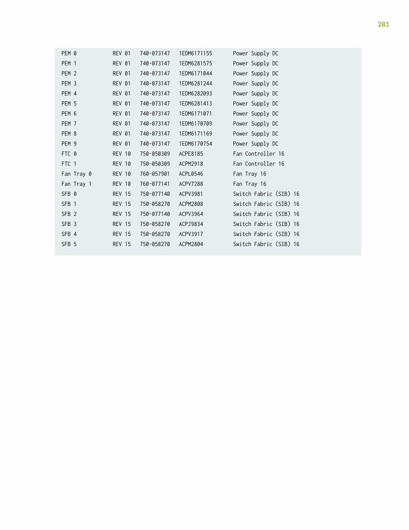
PEM 0 REV 01 740-073147 1EDM6171155 Power Supply DCPEM 1 REV 01 740-073147 1EDM6281575 Power Supply DCPEM 2 REV 01 740-073147 1EDM6171044 Power Supply DCPEM 3 REV 01 740-073147 1EDM6281244 Power Supply DCPEM 4 REV 01 740-073147 1EDM6282093 Power Supply DCPEM 5 REV 01 740-073147 1EDM6281413 Power Supply DCPEM 6 REV 01 740-073147 1EDM6171071 Power Supply DCPEM 7 REV 01 740-073147 1EDM6170709 Power Supply DCPEM 8 REV 01 740-073147 1EDM6171169 Power Supply DCPEM 9 REV 01 740-073147 1EDM6170754 Power Supply DCFTC 0 REV 10 750-050309 ACPE8185 Fan Controller 16FTC 1 REV 10 750-050309 ACPM2918 Fan Controller 16Fan Tray 0 REV 10 760-057901 ACPL0546 Fan Tray 16Fan Tray 1 REV 10 760-077141 ACPV7288 Fan Tray 16SFB 0 REV 15 750-077140 ACPV3981 Switch Fabric (SIB) 16SFB 1 REV 15 750-058270 ACPM2808 Switch Fabric (SIB) 16SFB 2 REV 15 750-077140 ACPV3964 Switch Fabric (SIB) 16SFB 3 REV 15 750-058270 ACPJ9834 Switch Fabric (SIB) 16SFB 4 REV 15 750-058270 ACPV3917 Switch Fabric (SIB) 16SFB 5 REV 15 750-058270 ACPM2804 Switch Fabric (SIB) 16
281

Locating the Chassis Serial Number ID Label on an MX10016
The serial number ID label is located on a label on the right side of the chassis. See Figure 133 on page282 for the location on an MX10016.
Figure 133: MX10016 Serial Number Label
Locating the Serial Number ID Labels on the Power Supplies
The power supplies installed in an MX10016 are field-replaceable units (FRUs). For each FRU, you mustremove the FRU from the router chassis to see the FRU serial number ID label.
282

• AC power supply—The serial number ID label is on the right side of the AC power supply. See Figure134 on page 283.
Figure 134: AC Power Supply Serial Number Location
283
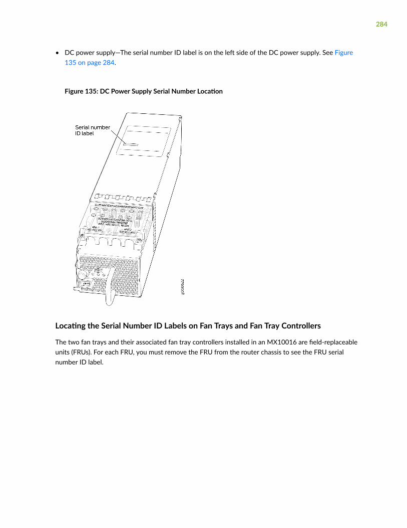
• DC power supply—The serial number ID label is on the left side of the DC power supply. See Figure135 on page 284.
Figure 135: DC Power Supply Serial Number Location
Locating the Serial Number ID Labels on Fan Trays and Fan Tray Controllers
The two fan trays and their associated fan tray controllers installed in an MX10016 are field-replaceableunits (FRUs). For each FRU, you must remove the FRU from the router chassis to see the FRU serialnumber ID label.
284
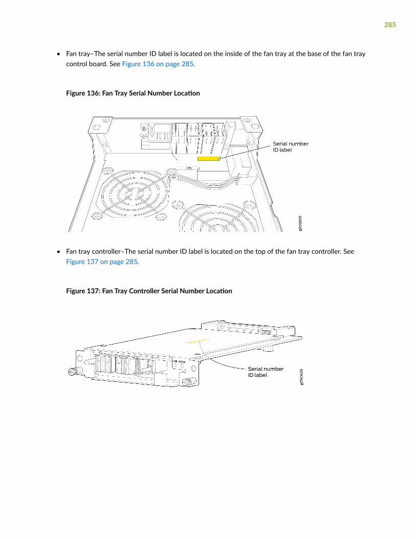
• Fan tray–The serial number ID label is located on the inside of the fan tray at the base of the fan traycontrol board. See Figure 136 on page 285.
Figure 136: Fan Tray Serial Number Location
• Fan tray controller–The serial number ID label is located on the top of the fan tray controller. SeeFigure 137 on page 285.
Figure 137: Fan Tray Controller Serial Number Location
285
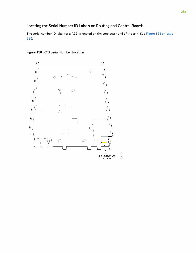
Locating the Serial Number ID Labels on Routing and Control Boards
The serial number ID label for a RCB is located on the connector end of the unit. See Figure 138 on page286.
Figure 138: RCB Serial Number Location
286

Locating the Serial Number ID Labels on a Line Card
The serial number ID label for a line card is located on the connector end of the card. See Figure 139 onpage 287.
Figure 139: Line Card Serial Number Location
Locating the Serial Number ID Labels on a Switch Fabric Board (SFB)
The serial number ID label for a SFB is located on the PC board. See Figure 140 on page 287.
Figure 140: SFB Serial Number Location
Contacting Customer Support to Obtain a Return Materials Authorizationfor an MX10016 Router or Component
If you are returning an MX10016 router or component to Juniper Networks for repair or replacement,you must first obtain a Return Materials Authorization (RMA) from the Juniper Networks TechnicalAssistance Center (JTAC).
287

After locating the serial number of the device or component you want to return, open a service requestwith Juniper Networks Technical Assistance Center (JTAC) on the Web or by telephone.
For instructions on locating the serial number of the device or component you want to return, see thefollowing device instructions:
• "Locating the Serial Number on an MX10016 Router or Component" on page 278
Before you request an RMA from JTAC, be prepared to provide the following information:
• Your existing service request number, if you have one
• Serial number of the component
• Your name, organization name, telephone number, fax number, and shipping address
• Details of the failure or problem
• Type of activity being performed on the device when the problem occurred
• Configuration data displayed by one or more show commands
You can contact JTAC 24 hours a day, seven days a week on the Web or by telephone:
• Service Request Manager: https://support.juniper.net/
• Telephone: +1-888-314-JTAC (+1-888-314-5822), toll-free in the USA, Canada, and Mexico
NOTE: For international or direct-dial options in countries without toll-free numbers, see https://www.juniper.net/support/requesting-support.html.
If you are contacting JTAC by telephone, enter your 12-digit service request number followed by thepound (#) key for an existing case, or press the star (*) key to be routed to the next available supportengineer.
The support representative validates your request and issues an RMA number for return of thecomponent.
288

Packing an MX10016 Router or Component for Shipping
IN THIS SECTION
Packing an MX10016 Chassis for Shipping | 289
Packing MX10016 Components for Shipping | 292
Follow this procedure if you are returning an MX10016 chassis or component to Juniper Networks forrepair or replacement.
Before you pack an MX10016 or component:
• Ensure that you have taken the necessary precautions to prevent electrostatic discharge (ESD)damage. See "Prevention of Electrostatic Discharge Damage" on page 321.
• Pack your chassis or component using one of these materials:
• Use the packing material from the replacement chassis or component.
• Retrieve the original shipping carton and packing materials.
Contact your JTAC representative if you do not have these materials, to learn about approved packingmaterials. See "Contacting Customer Support to Obtain a Return Materials Authorization for anMX10016 Router or Component" on page 287.
Ensure that you have the following parts and tools available:
• ESD grounding strap
• Electrostatic bag, one for each component
• If you are returning the chassis:
• A 13/32-in. or 10-mm open-end or socket wrench to install the bracket bolts on the chassis andshipping pallet
• An appropriate screwdriver for the mounting screws used on your rack
This topic covers:
Packing an MX10016 Chassis for Shipping
The MX10016 is shipped in a cardboard box that has a two-layer wooden pallet base with foamcushioning between the layers. The router chassis is bolted to the pallet base with four pallet fasteners,
289

two on each side of the chassis. See Figure 141 on page 290 for the stacking configuration of theMX10016.
Figure 141: Stacking Configuration for Packing the MX10016 Chassis
To pack an MX10016 for shipping:
1. Power down the chassis and remove the power cables. See "Powering Off an MX10016 Router" onpage 262.
2. Remove the cables that connect the MX10016 to all external devices.
290

3. Remove all line cards and pack them in their original shipping containers. See "Packing MX10016Components for Shipping" on page 292.
4. Install cover panels over blank slots.
Leave components that came installed in the chassis in the chassis, such as the RCBs or powersupplies.
5. Move the wooden pallet and packing material to a staging area as close to the router as possible.Make sure there is enough space to move the chassis from the rack to the wooden pallet.
6. Position a mechanical lift under the device. If a mechanical lift is not available, have three peoplesupport the weight of the router while another person uses the screwdriver to remove the front-mounting screws that attach the chassis-mounting brackets to the rack. To remove the router formthe rack, see "MX10016 Chassis Lifting Guidelines" on page 302 and "Removing an MX10016Router From a Four-Post Rack Using a Mechanical Lift" on page 265.
7. Remove the router from the rack (see ) and place the router on the shipping pallet. Position therouter on the pallet so that the front of the router is facing the silkscreened FRONT mark on thepallet. The pallet also has crop marks to guide you in positioning the chassis
8. Use the 13/32-in. or 10-mm open-end or socket wrench to install the four sets of brackets andbolts that secure the chassis to the wooden pallet.
9. Slide the plastic cover over the router chassis. The plastic cover is part of the router’s originalpacking materials.
10. Place the packing foam on top of and around the router.
11. Place the power cords in the box.
12. Remove the adjustable mounting brackets from the rack and place them and their connectingscrews in the accessory box.
13. If you are returning accessories or FRUs with the router, pack them as instructed in "PackingMX10016 Components for Shipping" on page 292.
14. Verify that all accessories are present. See "Comparing the MX10016 Order to the Packing List" onpage 138.
15. Slide the cardboard box over the chassis, making sure that the arrows on the box point up and thepallet fasteners to secure the cardboard box to the wooden pallet are near the bottom.
291
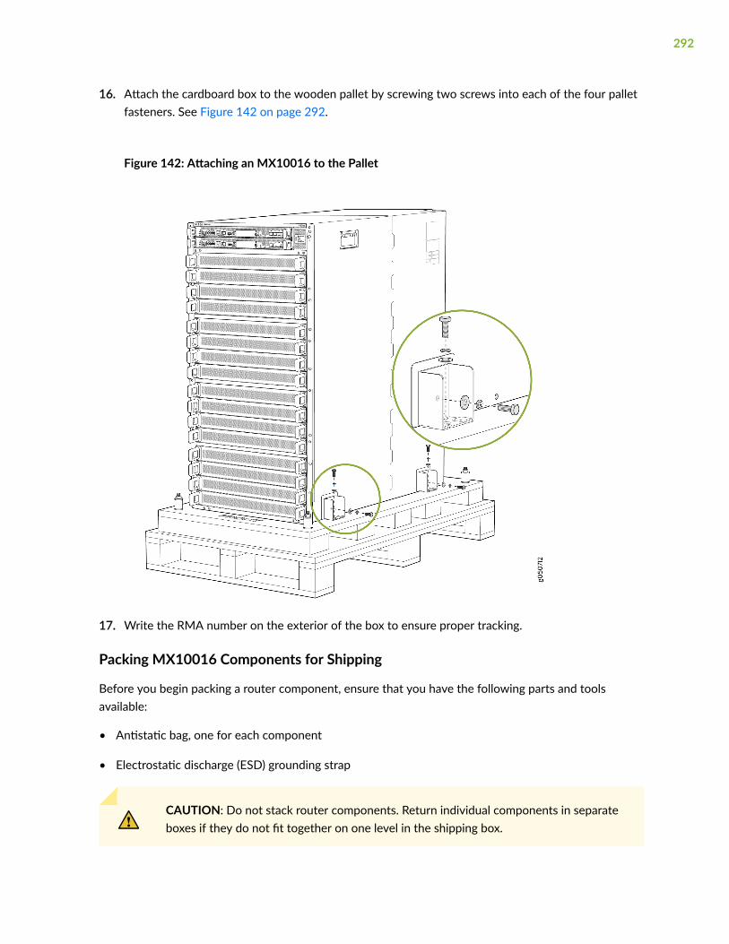
16. Attach the cardboard box to the wooden pallet by screwing two screws into each of the four palletfasteners. See Figure 142 on page 292.
Figure 142: Attaching an MX10016 to the Pallet
17. Write the RMA number on the exterior of the box to ensure proper tracking.
Packing MX10016 Components for Shipping
Before you begin packing a router component, ensure that you have the following parts and toolsavailable:
• Antistatic bag, one for each component
• Electrostatic discharge (ESD) grounding strap
CAUTION: Do not stack router components. Return individual components in separateboxes if they do not fit together on one level in the shipping box.
292

To pack and ship MX10016 components:
1. Place individual FRUs in antistatic bags.
2. Use the original packing materials if they are available. If the original packing materials are notavailable, ensure the component is adequately packed to prevent damage during transit. The packingmaterial you use must be able to support the weight of the component.
3. Ensure that the components are adequately protected with packing materials and packed so that thepieces are prevented from moving around inside the carton.
4. Close the top of the cardboard shipping box and seal it with packing tape.
5. Write the RMA number on the exterior of the box to ensure proper tracking.
293

7CHAPTER
Safety and Compliance Information
General Safety Guidelines and Warnings | 296
Definitions of Safety Warning Levels | 297
Qualified Personnel Warning | 299
Warning Statement for Norway and Sweden | 299
Fire Safety Requirements | 300
Installation Instructions Warning | 301
MX10016 Chassis Lifting Guidelines | 302
Restricted Access Warning | 302
Ramp Warning | 304
Rack-Mounting and Cabinet-Mounting Warnings | 304
Grounded Equipment Warning | 308
Radiation from Open Port Apertures Warning | 309
Laser and LED Safety Guidelines and Warnings | 310
Maintenance and Operational Safety Guidelines and Warnings | 313
General Electrical Safety Guidelines and Warnings | 319
Action to Take After an Electrical Accident | 320
Prevention of Electrostatic Discharge Damage | 321
AC Power Electrical Safety Guidelines | 322
AC Power Disconnection Warning | 323
DC Power Electrical Safety Guidelines for MX10016 Router | 324

DC Power Disconnection Warning | 325
DC Power Grounding Requirements and Warning | 327
DC Power Wiring Sequence Warning | 328
DC Power Wiring Terminations Warning | 329
Multiple Power Supplies Disconnection Warning | 330
TN Power Warning | 331
Agency Approvals and Compliance Statements | 332

General Safety Guidelines and Warnings
The following guidelines help ensure your safety and protect the device from damage. The list ofguidelines might not address all potentially hazardous situations in your working environment, so bealert and exercise good judgment at all times.
• Perform only the procedures explicitly described in the hardware documentation for this device.Make sure that only authorized service personnel perform other system services.
• Keep the area around the device clear and free from dust before, during, and after installation.
• Keep tools away from areas where people could trip over them while walking.
• Do not wear loose clothing or jewelry, such as rings, bracelets, or chains, which could become caughtin the device.
• Wear safety glasses if you are working under any conditions that could be hazardous to your eyes.
• Do not perform any actions that create a potential hazard to people or make the equipment unsafe.
• Never attempt to lift an object that is too heavy for one person to handle.
• Never install or manipulate wiring during electrical storms.
• Never install electrical jacks in wet locations unless the jacks are specifically designed for wetenvironments.
• Operate the device only when it is properly grounded.
• Follow the instructions in this guide to properly ground the device to earth.
• Replace fuses only with fuses of the same type and rating.
• Do not open or remove chassis covers or sheet-metal parts unless instructions are provided in thehardware documentation for this device. Such an action could cause severe electrical shock.
• Do not push or force any objects through any opening in the chassis frame. Such an action couldresult in electrical shock or fire.
• Avoid spilling liquid onto the chassis or onto any device component. Such an action could causeelectrical shock or damage the device.
• Avoid touching uninsulated electrical wires or terminals that have not been disconnected from theirpower source. Such an action could cause electrical shock.
296
• Some parts of the chassis, including AC and DC power supply surfaces, power supply unit handles,SFB card handles, and fan tray handles might become hot. The following label provides the warningof the hot surfaces on the chassis:
• Always ensure that all modules, power supplies, and cover panels are fully inserted and that theinstallation screws are fully tightened.
Definitions of Safety Warning Levels
The documentation uses the following levels of safety warnings (there are two Warning formats):
NOTE: You might find this information helpful in a particular situation, or you might overlook thisimportant information if it was not highlighted in a Note.
CAUTION: You need to observe the specified guidelines to prevent minor injury ordiscomfort to you or severe damage to the device.
Attention Veillez à respecter les consignes indiquées pour éviter toute incommodité oublessure légère, voire des dégâts graves pour l’appareil.
LASER WARNING: This symbol alerts you to the risk of personal injury from a laser.
Avertissement Ce symbole signale un risque de blessure provoquée par rayon laser.
WARNING: This symbol means danger. You are in a situation that could cause bodilyinjury. Before you work on any equipment, be aware of the hazards involved withelectrical circuitry and be familiar with standard practices for preventing accidents.
Waarschuwing Dit waarschuwingssymbool betekent gevaar. U verkeert in een situatiedie lichamelijk letsel kan veroorzaken. Voordat u aan enige apparatuur gaat werken,
297

dient u zich bewust te zijn van de bij elektrische schakelingen betrokken risico's en dientu op de hoogte te zijn van standaard maatregelen om ongelukken te voorkomen.
Varoitus Tämä varoitusmerkki merkitsee vaaraa. Olet tilanteessa, joka voi johtaaruumiinvammaan. Ennen kuin työskentelet minkään laitteiston parissa, ota selvääsähkökytkentöihin liittyvistä vaaroista ja tavanomaisista onnettomuuksienehkäisykeinoista.
Avertissement Ce symbole d'avertissement indique un danger. Vous vous trouvez dansune situation pouvant causer des blessures ou des dommages corporels. Avant detravailler sur un équipement, soyez conscient des dangers posés par les circuitsélectriques et familiarisez-vous avec les procédures couramment utilisées pour éviterles accidents.
Warnung Dieses Warnsymbol bedeutet Gefahr. Sie befinden sich in einer Situation, diezu einer Körperverletzung führen könnte. Bevor Sie mit der Arbeit an irgendeinemGerät beginnen, seien Sie sich der mit elektrischen Stromkreisen verbundenen Gefahrenund der Standardpraktiken zur Vermeidung von Unfällen bewußt.
Avvertenza Questo simbolo di avvertenza indica un pericolo. La situazione potrebbecausare infortuni alle persone. Prima di lavorare su qualsiasi apparecchiatura, occorreconoscere i pericoli relativi ai circuiti elettrici ed essere al corrente delle pratichestandard per la prevenzione di incidenti.
Advarsel Dette varselsymbolet betyr fare. Du befinner deg i en situasjon som kan føretil personskade. Før du utfører arbeid på utstyr, må du vare oppmerksom på defaremomentene som elektriske kretser innebærer, samt gjøre deg kjent med vanligpraksis når det gjelder å unngå ulykker.
Aviso Este símbolo de aviso indica perigo. Encontra-se numa situação que lhe poderácausar danos físicos. Antes de começar a trabalhar com qualquer equipamento,familiarize-se com os perigos relacionados com circuitos eléctricos, e com quaisquerpráticas comuns que possam prevenir possíveis acidentes.
¡Atención! Este símbolo de aviso significa peligro. Existe riesgo para su integridad física.Antes de manipular cualquier equipo, considerar los riesgos que entraña la corrienteeléctrica y familiarizarse con los procedimientos estándar de prevención de accidentes.
Varning! Denna varningssymbol signalerar fara. Du befinner dig i en situation som kanleda till personskada. Innan du utför arbete på någon utrustning måste du varamedveten om farorna med elkretsar och känna till vanligt förfarande för att förebyggaskador.
298

Qualified Personnel Warning
WARNING: Only trained and qualified personnel should install or replace the device.
Waarschuwing Installatie en reparaties mogen uitsluitend door getraind en bevoegdpersoneel uitgevoerd worden.
Varoitus Ainoastaan koulutettu ja pätevä henkilökunta saa asentaa tai vaihtaa tämänlaitteen.
Avertissement Tout installation ou remplacement de l'appareil doit être réalisé par dupersonnel qualifié et compétent.
Warnung Gerät nur von geschultem, qualifiziertem Personal installieren oderauswechseln lassen.
Avvertenza Solo personale addestrato e qualificato deve essere autorizzato ad installareo sostituire questo apparecchio.
Advarsel Kun kvalifisert personell med riktig opplæring bør montere eller bytte ut detteutstyret.
Aviso Este equipamento deverá ser instalado ou substituído apenas por pessoaldevidamente treinado e qualificado.
¡Atención! Estos equipos deben ser instalados y reemplazados exclusivamente porpersonal técnico adecuadamente preparado y capacitado.
Varning! Denna utrustning ska endast installeras och bytas ut av utbildad ochkvalificerad personal.
Warning Statement for Norway and Sweden
WARNING: The equipment must be connected to an earthed mains socket-outlet.
Advarsel Apparatet skal kobles til en jordet stikkontakt.
Varning! Apparaten skall anslutas till jordat nätuttag.
299

Fire Safety Requirements
IN THIS SECTION
Fire Suppression | 300
Fire Suppression Equipment | 300
In the event of a fire emergency, the safety of people is the primary concern. You should establishprocedures for protecting people in the event of a fire emergency, provide safety training, and properlyprovision fire-control equipment and fire extinguishers.
In addition, you should establish procedures to protect your equipment in the event of a fire emergency.Juniper Networks products should be installed in an environment suitable for electronic equipment. Werecommend that fire suppression equipment be available in the event of a fire in the vicinity of theequipment and that all local fire, safety, and electrical codes and ordinances be observed when youinstall and operate your equipment.
Fire Suppression
In the event of an electrical hazard or an electrical fire, you should first turn power off to the equipmentat the source. Then use a Type C fire extinguisher, which uses noncorrosive fire retardants, to extinguishthe fire.
Fire Suppression Equipment
Type C fire extinguishers, which use noncorrosive fire retardants such as carbon dioxide and Halotron™,are most effective for suppressing electrical fires. Type C fire extinguishers displace oxygen from thepoint of combustion to eliminate the fire. For extinguishing fire on or around equipment that draws airfrom the environment for cooling, you should use this type of inert oxygen displacement extinguisherinstead of an extinguisher that leaves residues on equipment.
Do not use multipurpose Type ABC chemical fire extinguishers (dry chemical fire extinguishers). Theprimary ingredient in these fire extinguishers is monoammonium phosphate, which is very sticky and
300
difficult to clean. In addition, in the presence of minute amounts of moisture, monoammoniumphosphate can become highly corrosive and corrodes most metals.
Any equipment in a room in which a chemical fire extinguisher has been discharged is subject topremature failure and unreliable operation. The equipment is considered to be irreparably damaged.
NOTE: To keep warranties effective, do not use a dry chemical fire extinguisher to control a fireat or near a Juniper Networks device. If a dry chemical fire extinguisher is used, the unit is nolonger eligible for coverage under a service agreement.
We recommend that you dispose of any irreparably damaged equipment in an environmentallyresponsible manner.
Installation Instructions Warning
WARNING: Read the installation instructions before you connect the device to a powersource.
Waarschuwing Raadpleeg de installatie-aanwijzingen voordat u het systeem met devoeding verbindt.
Varoitus Lue asennusohjeet ennen järjestelmän yhdistämistä virtalähteeseen.
Avertissement Avant de brancher le système sur la source d'alimentation, consulter lesdirectives d'installation.
Warnung Lesen Sie die Installationsanweisungen, bevor Sie das System an dieStromquelle anschließen.
Avvertenza Consultare le istruzioni di installazione prima di collegare il sistemaall'alimentatore.
Advarsel Les installasjonsinstruksjonene før systemet kobles til strømkilden.
Aviso Leia as instruções de instalação antes de ligar o sistema à sua fonte de energia.
¡Atención! Ver las instrucciones de instalación antes de conectar el sistema a la red dealimentación.
Varning! Läs installationsanvisningarna innan du kopplar systemet till dessströmförsörjningsenhet.
301

MX10016 Chassis Lifting Guidelines
The weight of a fully loaded MX10016 base AC configuration is approximately 522 lb (336.8 kg) and596 lb (270.34 kg) for the redundant AC configuration. Similarly, the weight of a redundant DCconfiguration is 591 lb (268.1 kg). Observe the following guidelines for lifting and moving a MX10016:
CAUTION: To avoid serious injury, do not attempt to move the MX10016 without amechanical lift.
• Before installing a MX10016, read the guidelines in "MX10016 Site Preparation Overview" on page91 to verify that the intended site meets the specified power, environmental, and clearancerequirements.
• Before moving the MX10016, disconnect all external cables.
• When raising the MX10016 into the rack using a mechanical life, have one person lift and align therouter with the rack while another person secures the router to the rack.
Restricted Access Warning
WARNING: This unit is intended for installation in restricted access areas. A restrictedaccess area is an area to which access can be gained only by service personnel throughthe use of a special tool, lock and key, or other means of security, and which iscontrolled by the authority responsible for the location.
Waarschuwing Dit toestel is bedoeld voor installatie op plaatsen met beperkte toegang.Een plaats met beperkte toegang is een plaats waar toegang slechts doorservicepersoneel verkregen kan worden door middel van een speciaal instrument, eenslot en sleutel, of een ander veiligheidsmiddel, en welke beheerd wordt door deoverheidsinstantie die verantwoordelijk is voor de locatie.
Varoitus Tämä laite on tarkoitettu asennettavaksi paikkaan, johon pääsy on rajoitettua.Paikka, johon pääsy on rajoitettua, tarkoittaa paikkaa, johon vain huoltohenkilöstöpääsee jonkin erikoistyökalun, lukkoon sopivan avaimen tai jonkin muun turvalaitteenavulla ja joka on paikasta vastuussa olevien toimivaltaisten henkilöiden valvoma.
302

Avertissement Cet appareil est à installer dans des zones d'accès réservé. Ces dernièressont des zones auxquelles seul le personnel de service peut accéder en utilisant un outilspécial, un mécanisme de verrouillage et une clé, ou tout autre moyen de sécurité.L'accès aux zones de sécurité est sous le contrôle de l'autorité responsable del'emplacement.
Warnung Diese Einheit ist zur Installation in Bereichen mit beschränktem Zutrittvorgesehen. Ein Bereich mit beschränktem Zutritt ist ein Bereich, zu dem nurWartungspersonal mit einem Spezialwerkzeugs, Schloß und Schlüssel oder andererSicherheitsvorkehrungen Zugang hat, und der von dem für die Anlage zuständigenGremium kontrolliert wird.
Avvertenza Questa unità deve essere installata in un'area ad accesso limitato. Un'areaad accesso limitato è un'area accessibile solo a personale di assistenza tramiteun'attrezzo speciale, lucchetto, o altri dispositivi di sicurezza, ed è controllatadall'autorità responsabile della zona.
Advarsel Denne enheten er laget for installasjon i områder med begrenset adgang. Etområde med begrenset adgang gir kun adgang til servicepersonale som bruker etspesielt verktøy, lås og nøkkel, eller en annen sikkerhetsanordning, og det kontrolleresav den autoriteten som er ansvarlig for området.
Aviso Esta unidade foi concebida para instalação em áreas de acesso restrito. Uma áreade acesso restrito é uma área à qual apenas tem acesso o pessoal de serviço autorizado,que possua uma ferramenta, chave e fechadura especial, ou qualquer outra forma desegurança. Esta área é controlada pela autoridade responsável pelo local.
¡Atención! Esta unidad ha sido diseñada para instalarse en áreas de acceso restringido.Área de acceso restringido significa un área a la que solamente tiene acceso el personalde servicio mediante la utilización de una herramienta especial, cerradura con llave, oalgún otro medio de seguridad, y que está bajo el control de la autoridad responsabledel local.
Varning! Denna enhet är avsedd för installation i områden med begränsat tillträde. Ettområde med begränsat tillträde får endast tillträdas av servicepersonal med ett specielltverktyg, lås och nyckel, eller annan säkerhetsanordning, och kontrolleras av denauktoritet som ansvarar för området.
303
Ramp Warning
WARNING: When installing the device, do not use a ramp inclined at more than 10degrees.
Waarschuwing Gebruik een oprijplaat niet onder een hoek van meer dan 10 graden.
Varoitus Älä käytä sellaista kaltevaa pintaa, jonka kaltevuus ylittää 10 astetta.
Avertissement Ne pas utiliser une rampe dont l'inclinaison est supérieure à 10 degrés.
Warnung Keine Rampen mit einer Neigung von mehr als 10 Grad verwenden.
Avvertenza Non usare una rampa con pendenza superiore a 10 gradi.
Advarsel Bruk aldri en rampe som heller mer enn 10 grader.
Aviso Não utilize uma rampa com uma inclinação superior a 10 graus.
¡Atención! No usar una rampa inclinada más de 10 grados.
Varning! Använd inte ramp med en lutning på mer än 10 grader.
Rack-Mounting and Cabinet-Mounting Warnings
Ensure that the rack or cabinet in which the device is installed is evenly and securely supported. Unevenmechanical loading could lead to a hazardous condition.
WARNING: To prevent bodily injury when mounting or servicing the device in a rack,take the following precautions to ensure that the system remains stable. The followingdirectives help maintain your safety:
• The device must be installed in a rack that is secured to the building structure.
• The device should be mounted at the bottom of the rack if it is the only unit in therack.
• When mounting the device on a partially filled rack, load the rack from the bottomto the top with the heaviest component at the bottom of the rack.
304

• If the rack is provided with stabilizing equipment, install the stabilizers beforemounting or servicing the device in the rack.
Waarschuwing Om lichamelijk letsel te voorkomen wanneer u dit toestel in een rekmonteert of het daar een servicebeurt geeft, moet u speciale voorzorgsmaatregelennemen om ervoor te zorgen dat het toestel stabiel blijft. De onderstaande richtlijnenworden verstrekt om uw veiligheid te verzekeren:
• De Juniper Networks switch moet in een stellage worden geïnstalleerd die aan eenbouwsel is verankerd.
• Dit toestel dient onderaan in het rek gemonteerd te worden als het toestel het enigein het rek is.
• Wanneer u dit toestel in een gedeeltelijk gevuld rek monteert, dient u het rek vanonderen naar boven te laden met het zwaarste onderdeel onderaan in het rek.
• Als het rek voorzien is van stabiliseringshulpmiddelen, dient u de stabilisatoren temonteren voordat u het toestel in het rek monteert of het daar een servicebeurtgeeft.
Varoitus Kun laite asetetaan telineeseen tai huolletaan sen ollessa telineessä, onnoudatettava erityisiä varotoimia järjestelmän vakavuuden säilyttämiseksi, jottavältytään loukkaantumiselta. Noudata seuraavia turvallisuusohjeita:
• Juniper Networks switch on asennettava telineeseen, joka on kiinnitettyrakennukseen.
• Jos telineessä ei ole muita laitteita, aseta laite telineen alaosaan.
• Jos laite asetetaan osaksi täytettyyn telineeseen, aloita kuormittaminen senalaosasta kaikkein raskaimmalla esineellä ja siirry sitten sen yläosaan.
• Jos telinettä varten on vakaimet, asenna ne ennen laitteen asettamista telineeseentai sen huoltamista siinä.
Avertissement Pour éviter toute blessure corporelle pendant les opérations de montageou de réparation de cette unité en casier, il convient de prendre des précautionsspéciales afin de maintenir la stabilité du système. Les directives ci-dessous sontdestinées à assurer la protection du personnel:
• Le rack sur lequel est monté le Juniper Networks switch doit être fixé à la structuredu bâtiment.
305

• Si cette unité constitue la seule unité montée en casier, elle doit être placée dans lebas.
• Si cette unité est montée dans un casier partiellement rempli, charger le casier debas en haut en plaçant l'élément le plus lourd dans le bas.
• Si le casier est équipé de dispositifs stabilisateurs, installer les stabilisateurs avant demonter ou de réparer l'unité en casier.
Warnung Zur Vermeidung von Körperverletzung beim Anbringen oder Warten dieserEinheit in einem Gestell müssen Sie besondere Vorkehrungen treffen, umsicherzustellen, daß das System stabil bleibt. Die folgenden Richtlinien sollen zurGewährleistung Ihrer Sicherheit dienen:
• Der Juniper Networks switch muß in einem Gestell installiert werden, das in derGebäudestruktur verankert ist.
• Wenn diese Einheit die einzige im Gestell ist, sollte sie unten im Gestell angebrachtwerden.
• Bei Anbringung dieser Einheit in einem zum Teil gefüllten Gestell ist das Gestell vonunten nach oben zu laden, wobei das schwerste Bauteil unten im Gestellanzubringen ist.
• Wird das Gestell mit Stabilisierungszubehör geliefert, sind zuerst die Stabilisatorenzu installieren, bevor Sie die Einheit im Gestell anbringen oder sie warten.
Avvertenza Per evitare infortuni fisici durante il montaggio o la manutenzione di questaunità in un supporto, occorre osservare speciali precauzioni per garantire che il sistemarimanga stabile. Le seguenti direttive vengono fornite per garantire la sicurezzapersonale:
• Il Juniper Networks switch deve essere installato in un telaio, il quale deve esserefissato alla struttura dell'edificio.
• Questa unità deve venire montata sul fondo del supporto, se si tratta dell'unica unitàda montare nel supporto.
• Quando questa unità viene montata in un supporto parzialmente pieno, caricare ilsupporto dal basso all'alto, con il componente più pesante sistemato sul fondo delsupporto.
• Se il supporto è dotato di dispositivi stabilizzanti, installare tali dispositivi prima dimontare o di procedere alla manutenzione dell'unità nel supporto.
306

Advarsel Unngå fysiske skader under montering eller reparasjonsarbeid på denneenheten når den befinner seg i et kabinett. Vær nøye med at systemet er stabilt.Følgende retningslinjer er gitt for å verne om sikkerheten:
• Juniper Networks switch må installeres i et stativ som er forankret tilbygningsstrukturen.
• Denne enheten bør monteres nederst i kabinettet hvis dette er den eneste enheten ikabinettet.
• Ved montering av denne enheten i et kabinett som er delvis fylt, skal kabinettetlastes fra bunnen og opp med den tyngste komponenten nederst i kabinettet.
• Hvis kabinettet er utstyrt med stabiliseringsutstyr, skal stabilisatorene installeres førmontering eller utføring av reparasjonsarbeid på enheten i kabinettet.
Aviso Para se prevenir contra danos corporais ao montar ou reparar esta unidade numaestante, deverá tomar precauções especiais para se certificar de que o sistema possuium suporte estável. As seguintes directrizes ajudá-lo-ão a efectuar o seu trabalho comsegurança:
• O Juniper Networks switch deverá ser instalado numa prateleira fixa à estrutura doedificio.
• Esta unidade deverá ser montada na parte inferior da estante, caso seja esta a únicaunidade a ser montada.
• Ao montar esta unidade numa estante parcialmente ocupada, coloque os itens maispesados na parte inferior da estante, arrumando-os de baixo para cima.
• Se a estante possuir um dispositivo de estabilização, instale-o antes de montar oureparar a unidade.
¡Atención! Para evitar lesiones durante el montaje de este equipo sobre un bastidor,oeriormente durante su mantenimiento, se debe poner mucho cuidado en que elsistema quede bien estable. Para garantizar su seguridad, proceda según las siguientesinstrucciones:
• El Juniper Networks switch debe instalarse en un bastidor fijado a la estructura deledificio.
• Colocar el equipo en la parte inferior del bastidor, cuando sea la única unidad en elmismo.
307
• Cuando este equipo se vaya a instalar en un bastidor parcialmente ocupado,comenzar la instalación desde la parte inferior hacia la superior colocando el equipomás pesado en la parte inferior.
• Si el bastidor dispone de dispositivos estabilizadores, instalar éstos antes de montaro proceder al mantenimiento del equipo instalado en el bastidor.
Varning! För att undvika kroppsskada när du installerar eller utför underhållsarbete pådenna enhet på en ställning måste du vidta särskilda försiktighetsåtgärder för attförsäkra dig om att systemet står stadigt. Följande riktlinjer ges för att trygga dinsäkerhet:
• Juniper Networks switch måste installeras i en ställning som är förankrad ibyggnadens struktur.
• Om denna enhet är den enda enheten på ställningen skall den installeras längst nedpå ställningen.
• Om denna enhet installeras på en delvis fylld ställning skall ställningen fyllas nedifrånoch upp, med de tyngsta enheterna längst ned på ställningen.
• Om ställningen är försedd med stabiliseringsdon skall dessa monteras fast innanenheten installeras eller underhålls på ställningen.
Grounded Equipment Warning
WARNING: This device must be properly grounded at all times. Follow the instructionsin this guide to properly ground the device to earth.
Waarschuwing Dit apparaat moet altijd goed geaard zijn. Volg de instructies in dezegids om het apparaat goed te aarden.
Varoitus Laitteen on oltava pysyvästi maadoitettu. Maadoita laite asianmukaisestinoudattamalla tämän oppaan ohjeita.
Avertissement L’appareil doit être correctement mis à la terre à tout moment. Suivez lesinstructions de ce guide pour correctement mettre l’appareil à la terre.
Warnung Das Gerät muss immer ordnungsgemäß geerdet sein. Befolgen Sie dieAnweisungen in dieser Anleitung, um das Gerät ordnungsgemäß zu erden.
308

Avvertenza Questo dispositivo deve sempre disporre di una connessione a massa.Seguire le istruzioni indicate in questa guida per connettere correttamente il dispositivoa massa.
Advarsel Denne enheten på jordes skikkelig hele tiden. Følg instruksjonene i denneveiledningen for å jorde enheten.
Aviso Este equipamento deverá estar ligado à terra. Siga las instrucciones en esta guíapara conectar correctamente este dispositivo a tierra.
¡Atención! Este dispositivo debe estar correctamente conectado a tierra en todomomento. Siga las instrucciones en esta guía para conectar correctamente estedispositivo a tierra.
Varning! Den här enheten måste vara ordentligt jordad. Följ instruktionerna i den härguiden för att jorda enheten ordentligt.
Radiation from Open Port Apertures Warning
LASER WARNING: Because invisible radiation might be emitted from the aperture of theport when no fiber cable is connected, avoid exposure to radiation and do not stare intoopen apertures.
Waarschuwing Aangezien onzichtbare straling vanuit de opening van de poort kan komenals er geen fiberkabel aangesloten is, dient blootstelling aan straling en het kijken in openopeningen vermeden te worden.
Varoitus Koska portin aukosta voi emittoitua näkymätöntä säteilyä, kun kuitukaapelia ei olekytkettynä, vältä säteilylle altistumista äläkä katso avoimiin aukkoihin.
Avertissement Des radiations invisibles à l'il nu pouvant traverser l'ouverture du portlorsqu'aucun câble en fibre optique n'y est connecté, il est recommandé de ne pas regarderfixement l'intérieur de ces ouvertures.
Warnung Aus der Port-Öffnung können unsichtbare Strahlen emittieren, wenn keinGlasfaserkabel angeschlossen ist. Vermeiden Sie es, sich den Strahlungen auszusetzen, undstarren Sie nicht in die Öffnungen!
309

Avvertenza Quando i cavi in fibra non sono inseriti, radiazioni invisibili possono essereemesse attraverso l'apertura della porta. Evitate di esporvi alle radiazioni e non guardatedirettamente nelle aperture.
Advarsel Unngå utsettelse for stråling, og stirr ikke inn i åpninger som er åpne, fordi usynligstråling kan emiteres fra portens åpning når det ikke er tilkoblet en fiberkabel.
Aviso Dada a possibilidade de emissão de radiação invisível através do orifício da via deacesso, quando esta não tiver nenhum cabo de fibra conectado, deverá evitar an EXposiçãoà radiação e não deverá olhar fixamente para orifícios que se encontrarem a descoberto.
¡Atención! Debido a que la apertura del puerto puede emitir radiación invisible cuando noexiste un cable de fibra conectado, evite mirar directamente a las aperturas para noexponerse a la radiación.
Varning! Osynlig strålning kan avges från en portöppning utan ansluten fiberkabel och dubör därför undvika att bli utsatt för strålning genom att inte stirra in i oskyddade öppningar.
Laser and LED Safety Guidelines and Warnings
IN THIS SECTION
General Laser Safety Guidelines | 311
Class 1 Laser Product Warning | 311
Class 1 LED Product Warning | 312
Laser Beam Warning | 312
Juniper Networks devices are equipped with laser transmitters, which are considered a Class 1 LaserProduct by the U.S. Food and Drug Administration and are evaluated as a Class 1 Laser Product per EN60825-1 requirements.
Observe the following guidelines and warnings:
310

General Laser Safety Guidelines
When working around ports that support optical transceivers, observe the following safety guidelines toprevent eye injury:
• Do not look into unterminated ports or at fibers that connect to unknown sources.
• Do not examine unterminated optical ports with optical instruments.
• Avoid direct exposure to the beam.
LASER WARNING: Unterminated optical connectors can emit invisible laser radiation. Thelens in the human eye focuses all the laser power on the retina, so focusing the eyedirectly on a laser source—even a low-power laser—could permanently damage the eye.
Avertissement Les connecteurs à fibre optique sans terminaison peuvent émettre unrayonnement laser invisible. Le cristallin de l’œil humain faisant converger toute lapuissance du laser sur la rétine, toute focalisation directe de l’œil sur une source laser, —même de faible puissance—, peut entraîner des lésions oculaires irréversibles.
Class 1 Laser Product Warning
LASER WARNING: Class 1 laser product.
Waarschuwing Klasse-1 laser produkt.
Varoitus Luokan 1 lasertuote.
Avertissement Produit laser de classe I.
Warnung Laserprodukt der Klasse 1.
Avvertenza Prodotto laser di Classe 1.
Advarsel Laserprodukt av klasse 1.
Aviso Produto laser de classe 1.
¡Atención! Producto láser Clase I.
Varning! Laserprodukt av klass 1.
311

Class 1 LED Product Warning
LASER WARNING: Class 1 LED product.
Waarschuwing Klasse 1 LED-product.
Varoitus Luokan 1 valodiodituote.
Avertissement Alarme de produit LED Class I.
Warnung Class 1 LED-Produktwarnung.
Avvertenza Avvertenza prodotto LED di Classe 1.
Advarsel LED-produkt i klasse 1.
Aviso Produto de classe 1 com LED.
¡Atención! Aviso sobre producto LED de Clase 1.
Varning! Lysdiodprodukt av klass 1.
Laser Beam Warning
LASER WARNING: Do not stare into the laser beam or view it directly with opticalinstruments.
Waarschuwing Niet in de straal staren of hem rechtstreeks bekijken met optischeinstrumenten.
Varoitus Älä katso säteeseen äläkä tarkastele sitä suoraan optisen laitteen avulla.
Avertissement Ne pas fixer le faisceau des yeux, ni l'observer directement à l'aided'instruments optiques.
Warnung Nicht direkt in den Strahl blicken und ihn nicht direkt mit optischen Gerätenprüfen.
Avvertenza Non fissare il raggio con gli occhi né usare strumenti ottici per osservarlodirettamente.
Advarsel Stirr eller se ikke direkte p strlen med optiske instrumenter.
312

Aviso Não olhe fixamente para o raio, nem olhe para ele directamente com instrumentosópticos.
¡Atención! No mirar fijamente el haz ni observarlo directamente con instrumentos ópticos.
Varning! Rikta inte blicken in mot strålen och titta inte direkt på den genom optiskainstrument.
Maintenance and Operational Safety Guidelines andWarnings
IN THIS SECTION
Battery Handling Warning | 313
Jewelry Removal Warning | 314
Lightning Activity Warning | 316
Operating Temperature Warning | 317
Product Disposal Warning | 318
While performing the maintenance activities for devices, observe the following guidelines and warnings:
Battery Handling Warning
WARNING: Replacing a battery incorrectly might result in an explosion. Replace abattery only with the same or equivalent type recommended by the manufacturer.Dispose of used batteries according to the manufacturer's instructions.
Waarschuwing Er is ontploffingsgevaar als de batterij verkeerd vervangen wordt.Vervang de batterij slechts met hetzelfde of een equivalent type dat door de fabrikant
313

aanbevolen is. Gebruikte batterijen dienen overeenkomstig fabrieksvoorschriftenweggeworpen te worden.
Varoitus Räjähdyksen vaara, jos akku on vaihdettu väärään akkuun. Käytä vaihtamiseenainoastaan saman- tai vastaavantyyppistä akkua, joka on valmistajan suosittelema.Hävitä käytetyt akut valmistajan ohjeiden mukaan.
Avertissement Danger d'explosion si la pile n'est pas remplacée correctement. Ne laremplacer que par une pile de type semblable ou équivalent, recommandée par lefabricant. Jeter les piles usagées conformément aux instructions du fabricant.
Warnung Bei Einsetzen einer falschen Batterie besteht Explosionsgefahr. Ersetzen Siedie Batterie nur durch den gleichen oder vom Hersteller empfohlenen Batterietyp.Entsorgen Sie die benutzten Batterien nach den Anweisungen des Herstellers.
Advarsel Det kan være fare for eksplosjon hvis batteriet skiftes på feil måte. Skift kunmed samme eller tilsvarende type som er anbefalt av produsenten. Kasser bruktebatterier i henhold til produsentens instruksjoner.
Avvertenza Pericolo di esplosione se la batteria non è installata correttamente.Sostituire solo con una di tipo uguale o equivalente, consigliata dal produttore. Eliminarele batterie usate secondo le istruzioni del produttore.
Aviso Existe perigo de explosão se a bateria for substituída incorrectamente. Substituaa bateria por uma bateria igual ou de um tipo equivalente recomendado pelo fabricante.Destrua as baterias usadas conforme as instruções do fabricante.
¡Atención! Existe peligro de explosión si la batería se reemplaza de manera incorrecta.Reemplazar la baterían EXclusivamente con el mismo tipo o el equivalenterecomendado por el fabricante. Desechar las baterías gastadas según las instruccionesdel fabricante.
Varning! Explosionsfara vid felaktigt batteribyte. Ersätt endast batteriet med sammabatterityp som rekommenderas av tillverkaren eller motsvarande. Följ tillverkarensanvisningar vid kassering av använda batterier.
Jewelry Removal Warning
WARNING: Before working on equipment that is connected to power lines, removejewelry, including rings, necklaces, and watches. Metal objects heat up when connectedto power and ground and can cause serious burns or can be welded to the terminals.
314

Waarschuwing Alvorens aan apparatuur te werken die met elektrische leidingen isverbonden, sieraden (inclusief ringen, kettingen en horloges) verwijderen. Metalenvoorwerpen worden warm wanneer ze met stroom en aarde zijn verbonden, en kunnenernstige brandwonden veroorzaken of het metalen voorwerp aan de aansluitklemmenlassen.
Varoitus Ennen kuin työskentelet voimavirtajohtoihin kytkettyjen laitteiden parissa, otapois kaikki korut (sormukset, kaulakorut ja kellot mukaan lukien). Metalliesineetkuumenevat, kun ne ovat yhteydessä sähkövirran ja maan kanssa, ja ne voivat aiheuttaavakavia palovammoja tai hitsata metalliesineet kiinni liitäntänapoihin.
Avertissement Avant d'accéder à cet équipement connecté aux lignes électriques, ôtertout bijou (anneaux, colliers et montres compris). Lorsqu'ils sont branchés àl'alimentation et reliés à la terre, les objets métalliques chauffent, ce qui peut provoquerdes blessures graves ou souder l'objet métallique aux bornes.
Warnung Vor der Arbeit an Geräten, die an das Netz angeschlossen sind, jeglichenSchmuck (einschließlich Ringe, Ketten und Uhren) abnehmen. Metallgegenständeerhitzen sich, wenn sie an das Netz und die Erde angeschlossen werden, und könnenschwere Verbrennungen verursachen oder an die Anschlußklemmen angeschweißtwerden.
Avvertenza Prima di intervenire su apparecchiature collegate alle linee di alimentazione,togliersi qualsiasi monile (inclusi anelli, collane, braccialetti ed orologi). Gli oggettimetallici si riscaldano quando sono collegati tra punti di alimentazione e massa: possonocausare ustioni gravi oppure il metallo può saldarsi ai terminali.
Advarsel Fjern alle smykker (inkludert ringer, halskjeder og klokker) før du skal arbeidepå utstyr som er koblet til kraftledninger. Metallgjenstander som er koblet tilkraftledninger og jord blir svært varme og kan forårsake alvorlige brannskader ellersmelte fast til polene.
Aviso Antes de trabalhar em equipamento que esteja ligado a linhas de corrente, retiretodas as jóias que estiver a usar (incluindo anéis, fios e relógios). Os objectos metálicosaquecerão em contacto com a corrente e em contacto com a ligação à terra, podendocausar queimaduras graves ou ficarem soldados aos terminais.
¡Atención! Antes de operar sobre equipos conectados a líneas de alimentación, quitarselas joyas (incluidos anillos, collares y relojes). Los objetos de metal se calientan cuandose conectan a la alimentación y a tierra, lo que puede ocasionar quemaduras graves oque los objetos metálicos queden soldados a los bornes.
315
Varning! Tag av alla smycken (inklusive ringar, halsband och armbandsur) innan duarbetar på utrustning som är kopplad till kraftledningar. Metallobjekt hettas upp när dekopplas ihop med ström och jord och kan förorsaka allvarliga brännskador; metallobjektkan också sammansvetsas med kontakterna.
Lightning Activity Warning
WARNING: Do not work on the system or connect or disconnect cables during periodsof lightning activity.
Waarschuwing Tijdens onweer dat gepaard gaat met bliksem, dient u niet aan hetsysteem te werken of kabels aan te sluiten of te ontkoppelen.
Varoitus Älä työskentele järjestelmän parissa äläkä yhdistä tai irrota kaapeleitaukkosilmalla.
Avertissement Ne pas travailler sur le système ni brancher ou débrancher les câblespendant un orage.
Warnung Arbeiten Sie nicht am System und schließen Sie keine Kabel an bzw. trennenSie keine ab, wenn es gewittert.
Avvertenza Non lavorare sul sistema o collegare oppure scollegare i cavi durante untemporale con fulmini.
Advarsel Utfør aldri arbeid på systemet, eller koble kabler til eller fra systemet når dettordner eller lyner.
Aviso Não trabalhe no sistema ou ligue e desligue cabos durante períodos de mautempo (trovoada).
¡Atención! No operar el sistema ni conectar o desconectar cables durante el transcursode descargas eléctricas en la atmósfera.
Varning! Vid åska skall du aldrig utföra arbete på systemet eller ansluta eller koppla losskablar.
316

Operating Temperature Warning
WARNING: To prevent the device from overheating, do not operate it in an area thatexceeds the maximum recommended ambient temperature. To prevent airflowrestriction, allow at least 6 in. (15.2 cm) of clearance around the ventilation openings.
Waarschuwing Om te voorkomen dat welke switch van de Juniper Networks router danook oververhit raakt, dient u deze niet te bedienen op een plaats waar de maximaleaanbevolen omgevingstemperatuur van 40° C wordt overschreden. Om te voorkomendat de luchtstroom wordt beperkt, dient er minstens 15,2 cm speling rond de ventilatie-openingen te zijn.
Varoitus Ettei Juniper Networks switch-sarjan reititin ylikuumentuisi, sitä ei saa käyttäätilassa, jonka lämpötila ylittää korkeimman suositellun ympäristölämpötilan 40° C. Etteiilmanvaihto estyisi, tuuletusaukkojen ympärille on jätettävä ainakin 15,2 cm tilaa.
Avertissement Pour éviter toute surchauffe des routeurs de la gamme JuniperNetworks switch, ne l'utilisez pas dans une zone où la température ambiante estsupérieure à 40° C. Pour permettre un flot d'air constant, dégagez un espace d'au moins15,2 cm autour des ouvertures de ventilations.
Warnung Um einen Router der switch vor Überhitzung zu schützen, darf dieser nicht ineiner Gegend betrieben werden, in der die Umgebungstemperatur das empfohleneMaximum von 40° C überschreitet. Um Lüftungsverschluß zu verhindern, achten Siedarauf, daß mindestens 15,2 cm lichter Raum um die Lüftungsöffnungen herum freibleibt.
Avvertenza Per evitare il surriscaldamento dei switch, non adoperateli in un locale cheecceda la temperatura ambientale massima di 40° C. Per evitare che la circolazionedell'aria sia impedita, lasciate uno spazio di almeno 15.2 cm di fronte alle aperture delleventole.
Advarsel Unngå overoppheting av eventuelle rutere i Juniper Networks switch Disseskal ikke brukes på steder der den anbefalte maksimale omgivelsestemperaturenoverstiger 40° C (104° F). Sørg for at klaringen rundt lufteåpningene er minst 15,2 cm(6 tommer) for å forhindre nedsatt luftsirkulasjon.
Aviso Para evitar o sobreaquecimento do encaminhador Juniper Networks switch, nãoutilize este equipamento numa área que exceda a temperatura máxima recomendada de40° C. Para evitar a restrição à circulação de ar, deixe pelo menos um espaço de 15,2 cmà volta das aberturas de ventilação.
317

¡Atención! Para impedir que un encaminador de la serie Juniper Networks switch serecaliente, no lo haga funcionar en un área en la que se supere la temperatura ambientemáxima recomendada de 40° C. Para impedir la restricción de la entrada de aire, deje unespacio mínimo de 15,2 cm alrededor de las aperturas para ventilación.
Varning! Förhindra att en Juniper Networks switch överhettas genom att inte användaden i ett område där den maximalt rekommenderade omgivningstemperaturen på 40° Cöverskrids. Förhindra att luftcirkulationen inskränks genom att se till att det finns frittutrymme på minst 15,2 cm omkring ventilationsöppningarna.
Product Disposal Warning
WARNING: Disposal of this device must be handled according to all national laws andregulations.
Waarschuwing Dit produkt dient volgens alle landelijke wetten en voorschriften teworden afgedankt.
Varoitus Tämän tuotteen lopullisesta hävittämisestä tulee huolehtia kaikkiavaltakunnallisia lakeja ja säännöksiä noudattaen.
Avertissement La mise au rebut définitive de ce produit doit être effectuéeconformément à toutes les lois et réglementations en vigueur.
Warnung Dieses Produkt muß den geltenden Gesetzen und Vorschriften entsprechendentsorgt werden.
Avvertenza L'eliminazione finale di questo prodotto deve essere eseguita osservando lenormative italiane vigenti in materia
Advarsel Endelig disponering av dette produktet må skje i henhold til nasjonale lover ogforskrifter.
Aviso A descartagem final deste produto deverá ser efectuada de acordo com osregulamentos e a legislação nacional.
¡Atención! El desecho final de este producto debe realizarse según todas las leyes yregulaciones nacionales
Varning! Slutlig kassering av denna produkt bör skötas i enlighet med landets alla lagaroch föreskrifter.
318

General Electrical Safety Guidelines and Warnings
WARNING: Certain ports on the device are designed for use as intrabuilding (within-the-building) interfaces only (Type 2 or Type 4 ports as described in GR-1089-CORE)and require isolation from the exposed outside plant (OSP) cabling. To comply withNEBS requirements and protect against lightning surges and commercial powerdisturbances, the intrabuilding ports must not be metallically connected to interfacesthat connect to the OSP or its wiring. The intrabuilding ports on the device are suitablefor connection to intrabuilding or unexposed wiring or cabling only. The addition ofprimary protectors is not sufficient protection for connecting these interfacesmetallically to OSP wiring.
Avertissement Certains ports de l’appareil sont destinés à un usage en intérieuruniquement (ports Type 2 ou Type 4 tels que décrits dans le document GR-1089-CORE)et doivent être isolés du câblage de l’installation extérieure exposée. Pour respecter lesexigences NEBS et assurer une protection contre la foudre et les perturbations detension secteur, les ports pour intérieur ne doivent pas être raccordés physiquementaux interfaces prévues pour la connexion à l’installation extérieure ou à son câblage. Lesports pour intérieur de l’appareil sont réservés au raccordement de câbles pour intérieurou non exposés uniquement. L’ajout de protections ne constitue pas une précautionsuffisante pour raccorder physiquement ces interfaces au câblage de l’installationextérieure.
CAUTION: Before removing or installing components of a device, connect anelectrostatic discharge (ESD) grounding strap to an ESD point and wrap and fasten theother end of the strap around your bare wrist. Failure to use an ESD grounding strapcould result in damage to the device.
Attention Avant de retirer ou d’installer des composants d’un appareil, raccordez unbracelet antistatique à un point de décharge électrostatique et fixez le bracelet à votrepoignet nu. L’absence de port d’un bracelet antistatique pourrait provoquer des dégâtssur l’appareil.
• Install the device in compliance with the following local, national, and international electrical codes:
• United States—National Fire Protection Association (NFPA 70), United States National ElectricalCode.
• Other countries—International Electromechanical Commission (IEC) 60364, Part 1 through Part 7.
• Evaluated to the TN power system.
319

• Canada—Canadian Electrical Code, Part 1, CSA C22.1.
• Suitable for installation in Information Technology Rooms in accordance with Article 645 of theNational Electrical Code and NFPA 75.
Peut être installé dans des salles de matériel de traitement de l’information conformément àl’article 645 du National Electrical Code et à la NFPA 75.
• Locate the emergency power-off switch for the room in which you are working so that if an electricalaccident occurs, you can quickly turn off the power.
• Make sure that grounding surfaces are cleaned and brought to a bright finish before groundingconnections are made.
• Do not work alone if potentially hazardous conditions exist anywhere in your workspace.
• Never assume that power is disconnected from a circuit. Always check the circuit before starting towork.
• Carefully look for possible hazards in your work area, such as moist floors, ungrounded powerextension cords, and missing safety grounds.
• Operate the device within marked electrical ratings and product usage instructions.
• To ensure that the device and peripheral equipment function safely and correctly, use the cables andconnectors specified for the attached peripheral equipment, and make certain they are in goodcondition.
You can remove and replace many device components without powering off or disconnecting power tothe device, as detailed elsewhere in the hardware documentation for this device. Never installequipment that appears to be damaged.
Action to Take After an Electrical Accident
If an electrical accident results in an injury, take the following actions in this order:
1. Use caution. Be aware of potentially hazardous conditions that could cause further injury.
2. Disconnect power from the device.
3. If possible, send another person to get medical aid. Otherwise, assess the condition of the victim,then call for help.
320

Prevention of Electrostatic Discharge Damage
Device components that are shipped in antistatic bags are sensitive to damage from static electricity.Some components can be impaired by voltages as low as 30 V. You can easily generate potentiallydamaging static voltages whenever you handle plastic or foam packing material or if you movecomponents across plastic or carpets. Observe the following guidelines to minimize the potential forelectrostatic discharge (ESD) damage, which can cause intermittent or complete component failures:
• Always use an ESD wrist strap when you are handling components that are subject to ESD damage,and make sure that it is in direct contact with your skin.
If a grounding strap is not available, hold the component in its antistatic bag (see Figure 143 on page322) in one hand and touch the exposed, bare metal of the device with the other hand immediatelybefore inserting the component into the device.
WARNING: For safety, periodically check the resistance value of the ESD groundingstrap. The measurement must be in the range 1 through 10 Mohms.
Avertissement Par mesure de sécurité, vérifiez régulièrement la résistance du braceletantistatique. Cette valeur doit être comprise entre 1 et 10 mégohms (Mohms).
• When handling any component that is subject to ESD damage and that is removed from the device,make sure the equipment end of your ESD wrist strap is attached to the ESD point on the chassis.
If no grounding strap is available, touch the exposed, bare metal of the device to ground yourselfbefore handling the component.
• Avoid contact between the component that is subject to ESD damage and your clothing. ESDvoltages emitted from clothing can damage components.
321

• When removing or installing a component that is subject to ESD damage, always place it component-side up on an antistatic surface, in an antistatic card rack, or in an antistatic bag (see Figure 143 onpage 322). If you are returning a component, place it in an antistatic bag before packing it.
Figure 143: Placing a Component into an Antistatic Bag
CAUTION: ANSI/TIA/EIA-568 cables such as Category 5e and Category 6 can getelectrostatically charged. To dissipate this charge, always ground the cables to a suitableand safe earth ground before connecting them to the system.
Attention Les câbles ANSI/TIA/EIA-568, par exemple Cat 5e et Cat 6, peuventemmagasiner des charges électrostatiques. Pour évacuer ces charges, reliez toujours lescâbles à une prise de terre adaptée avant de les raccorder au système.
AC Power Electrical Safety Guidelines
The following electrical safety guidelines apply to AC-powered devices:
• Note the following warnings printed on the device:
“CAUTION: THIS UNIT HAS MORE THAN ONE POWER SUPPLY CORD. DISCONNECT ALLPOWER SUPPLY CORDS BEFORE SERVICING TO AVOID ELECTRIC SHOCK.”
322
“ATTENTION: CET APPAREIL COMPORTE PLUS D'UN CORDON D'ALIMENTATION. AFIN DEPRÉVENIR LES CHOCS ÉLECTRIQUES, DÉBRANCHER TOUT CORDON D'ALIMENTATION AVANTDE FAIRE LE DÉPANNAGE.”
• AC-powered devices are shipped with a three-wire electrical cord with a grounding-type plug thatfits only a grounding-type power outlet. Do not circumvent this safety feature. Equipment groundingmust comply with local and national electrical codes.
• You must provide an external certified circuit breaker (2-pole circuit breaker or 4-pole circuit breakerbased on your device) rated minimum 20 A in the building installation.
• The power cord serves as the main disconnecting device for the AC-powered device. The socketoutlet must be near the AC-powered device and be easily accessible.
• For devices that have more than one power supply connection, you must ensure that all powerconnections are fully disconnected so that power to the device is completely removed to preventelectric shock. To disconnect power, unplug all power cords (one for each power supply).
Power Cable Warning (Japanese)
WARNING: The attached power cable is only for this product. Do not use the cable for another product.
AC Power Disconnection Warning
WARNING: Before working on the device or near power supplies, unplug all the powercords from an AC-powered device.
Waarschuwing Voordat u aan een frame of in de nabijheid van voedingen werkt, dient ubij wisselstroom toestellen de stekker van het netsnoer uit het stopcontact te halen.
Varoitus Kytke irti vaihtovirtalaitteiden virtajohto, ennen kuin teet mitäänasennuspohjalle tai työskentelet virtalähteiden läheisyydessä.
323

Avertissement Avant de travailler sur un châssis ou à proximité d'une alimentationélectrique, débrancher le cordon d'alimentation des unités en courant alternatif.
Warnung Bevor Sie an einem Chassis oder in der Nähe von Netzgeräten arbeiten,ziehen Sie bei Wechselstromeinheiten das Netzkabel ab bzw.
Avvertenza Prima di lavorare su un telaio o intorno ad alimentatori, scollegare il cavo dialimentazione sulle unità CA.
Advarsel Før det utføres arbeid på kabinettet eller det arbeides i nærheten avstrømforsyningsenheter, skal strømledningen trekkes ut på vekselstrømsenheter.
Aviso Antes de trabalhar num chassis, ou antes de trabalhar perto de unidades defornecimento de energia, desligue o cabo de alimentação nas unidades de correntealternada.
¡Atención! Antes de manipular el chasis de un equipo o trabajar cerca de una fuente dealimentación, desenchufar el cable de alimentación en los equipos de corriente alterna(CA).
Varning! Innan du arbetar med ett chassi eller nära strömförsörjningsenheter skall du förväxelströmsenheter dra ur nätsladden.
DC Power Electrical Safety Guidelines for MX10016Router
This topic applies to hardware devices in the MX10016 router.
• A DC-powered device is equipped with a DC terminal block that is rated for the power requirementsof a maximally configured device.
NOTE: To supply sufficient power, terminate the DC input wiring on a facility DC source thatis capable of supplying:
• Minimum of 60 A at –48 VDC for MX10016 routers
Incorporate an easily accessible disconnect device into the facility wiring. Be sure to connect theground wire or conduit to a solid office earth ground. A closed loop ring is recommended forterminating the ground conductor at the ground stud.
324
• Run two wires from the circuit breaker box to a source of 48 VDC.
• A DC-powered device that is equipped with a DC terminal block is intended only for installation in arestricted-access location. In the United States, a restricted-access area is one in accordance withArticles 110-16, 110-17, and 110-18 of the National Electrical Code ANSI/NFPA 70.
NOTE: Primary overcurrent protection is provided by the building circuit breaker. This breakermust protect against excess currents, short circuits, and earth grounding faults in accordancewith NEC ANSI/NFPA 70.
• Ensure that the polarity of the DC input wiring is correct. Under certain conditions, connections withreversed polarity might trip the primary circuit breaker or damage the equipment.
• For personal safety, connect the green and yellow wire to safety (earth) ground at both the deviceand the supply side of the DC wiring.
• The marked input voltage of –48 VDC for a DC-powered device is the nominal voltage associatedwith the battery circuit, and any higher voltages are only to be associated with float voltages for thecharging function.
• Because the device is a positive ground system, you must connect the positive lead to the terminallabeled RTN, the negative lead to the terminal labeled –48 VDC, and the earth ground to the devicegrounding points.
DC Power Disconnection Warning
WARNING: Before performing any of the DC power procedures, ensure that power isremoved from the DC circuit. To ensure that all power is off, locate the circuit breakeron the panel board that services the DC circuit, switch the circuit breaker to the OFFposition, and tape the device handle of the circuit breaker in the OFF position.
Waarschuwing Voordat u een van de onderstaande procedures uitvoert, dient u tecontroleren of de stroom naar het gelijkstroom circuit uitgeschakeld is. Om u ervan teverzekeren dat alle stroom UIT is geschakeld, kiest u op het schakelbord destroomverbreker die het gelijkstroom circuit bedient, draait de stroomverbreker naar deUIT positie en plakt de schakelaarhendel van de stroomverbreker met plakband in deUIT positie vast.
325

Varoitus Varmista, että tasavirtapiirissä ei ole virtaa ennen seuraavien toimenpiteidensuorittamista. Varmistaaksesi, että virta on KATKAISTU täysin, paikanna tasavirrastahuolehtivassa kojetaulussa sijaitseva suojakytkin, käännä suojakytkin KATKAISTU-asentoon ja teippaa suojakytkimen varsi niin, että se pysyy KATKAISTU-asennossa.
Avertissement Avant de pratiquer l'une quelconque des procédures ci-dessous, vérifierque le circuit en courant continu n'est plus sous tension. Pour en être sûr, localiser ledisjoncteur situé sur le panneau de service du circuit en courant continu, placer ledisjoncteur en position fermée (OFF) et, à l'aide d'un ruban adhésif, bloquer la poignéedu disjoncteur en position OFF.
Warnung Vor Ausführung der folgenden Vorgänge ist sicherzustellen, daß dieGleichstromschaltung keinen Strom erhält. Um sicherzustellen, daß sämtlicher Stromabgestellt ist, machen Sie auf der Schalttafel den Unterbrecher für dieGleichstromschaltung ausfindig, stellen Sie den Unterbrecher auf AUS, und kleben Sieden Schaltergriff des Unterbrechers mit Klebeband in der AUS-Stellung fest.
Avvertenza Prima di svolgere una qualsiasi delle procedure seguenti, verificare che ilcircuito CC non sia alimentato. Per verificare che tutta l'alimentazione sia scollegata(OFF), individuare l'interruttore automatico sul quadro strumenti che alimenta il circuitoCC, mettere l'interruttore in posizione OFF e fissarlo con nastro adesivo in taleposizione.
Advarsel Før noen av disse prosedyrene utføres, kontroller at strømmen er frakobletlikestrømkretsen. Sørg for at all strøm er slått AV. Dette gjøres ved å lokaliserestrømbryteren på brytertavlen som betjener likestrømkretsen, slå strømbryteren AV ogteipe bryterhåndtaket på strømbryteren i AV-stilling.
Aviso Antes de executar um dos seguintes procedimentos, certifique-se que desligou afonte de alimentação de energia do circuito de corrente contínua. Para se assegurar quetoda a corrente foi DESLIGADA, localize o disjuntor no painel que serve o circuito decorrente contínua e coloque-o na posição OFF (Desligado), segurando nessa posição amanivela do interruptor do disjuntor com fita isoladora.
¡Atención! Antes de proceder con los siguientes pasos, comprobar que la alimentacióndel circuito de corriente continua (CC) esté cortada (OFF). Para asegurarse de que todala alimentación esté cortada (OFF), localizar el interruptor automático en el panel quealimenta al circuito de corriente continua, cambiar el interruptor automático a laposición de Apagado (OFF), y sujetar con cinta la palanca del interruptor automático enposición de Apagado (OFF).
Varning! Innan du utför någon av följande procedurer måste du kontrollera attströmförsörjningen till likströmskretsen är bruten. Kontrollera att all strömförsörjning är
326
BRUTEN genom att slå AV det överspänningsskydd som skyddar likströmskretsen ochtejpa fast överspänningsskyddets omkopplare i FRÅN-läget.
DC Power Grounding Requirements and Warning
An insulated grounding conductor that is identical in size to the grounded and ungrounded branchcircuit supply conductors but is identifiable by green and yellow stripes is installed as part of the branchcircuit that supplies the device. The grounding conductor is a separately derived system at the supplytransformer or motor generator set.
WARNING: When you install the device, the ground connection must always be madefirst and disconnected last.
Waarschuwing Bij de installatie van het toestel moet de aardverbinding altijd het eersteworden gemaakt en het laatste worden losgemaakt.
Varoitus Laitetta asennettaessa on maahan yhdistäminen aina tehtävä ensiksi jamaadoituksen irti kytkeminen viimeiseksi.
Avertissement Lors de l'installation de l'appareil, la mise à la terre doit toujours êtreconnectée en premier et déconnectée en dernier.
Warnung Der Erdanschluß muß bei der Installation der Einheit immer zuerst hergestelltund zuletzt abgetrennt werden.
Avvertenza In fase di installazione dell'unità, eseguire sempre per primo il collegamentoa massa e disconnetterlo per ultimo.
Advarsel Når enheten installeres, må jordledningen alltid tilkobles først og frakobles sist.
Aviso Ao instalar a unidade, a ligação à terra deverá ser sempre a primeira a ser ligada, ea última a ser desligada.
¡Atención! Al instalar el equipo, conectar la tierra la primera y desconectarla la última.
Varning! Vid installation av enheten måste jordledningen alltid anslutas först ochkopplas bort sist.
327

DC Power Wiring Sequence Warning
WARNING: Wire the DC power supply using the appropriate lugs. When connectingpower, the proper wiring sequence is ground to ground, +RTN to +RTN, then –48 V to –48 V. When disconnecting power, the proper wiring sequence is –48 V to –48 V, +RTNto +RTN, then ground to ground. Note that the ground wire must always be connectedfirst and disconnected last.
Waarschuwing De juiste bedradingsvolgorde verbonden is aarde naar aarde, +RTN naar+RTN, en –48 V naar – 48 V. De juiste bedradingsvolgorde losgemaakt is en –48 naar –48 V, +RTN naar +RTN, aarde naar aarde.
Varoitus Oikea yhdistettava kytkentajarjestys on maajohto maajohtoon, +RTN varten+RTN, –48 V varten – 48 V. Oikea irrotettava kytkentajarjestys on –48 V varten – 48 V,+RTN varten +RTN, maajohto maajohtoon.
Avertissement Câblez l'approvisionnement d'alimentation CC En utilisant les crochetsappropriés à l'extrémité de câblage. En reliant la puissance, l'ordre approprié de câblageest rectifié pour rectifier, +RTN à +RTN, puis –48 V à –48 V. En débranchant lapuissance, l'ordre approprié de câblage est –48 V à –48 V, +RTN à +RTN, a alors rectifiépour rectifier. Notez que le fil de masse devrait toujours être relié d'abord et débranchépour la dernière fois. Notez que le fil de masse devrait toujours être relié d'abord etdébranché pour la dernière fois.
Warnung Die Stromzufuhr ist nur mit geeigneten Ringösen an das DC Netzteilanzuschliessen. Die richtige Anschlusssequenz ist: Erdanschluss zu Erdanschluss, +RTNzu +RTN und dann -48V zu -48V. Die richtige Sequenz zum Abtrennen derStromversorgung ist -48V zu -48V, +RTN zu +RTN und dann Erdanschluss zuErdanschluss. Es ist zu beachten dass der Erdanschluss immer zuerst angeschlossen undals letztes abgetrennt wird.
Avvertenza Mostra la morsettiera dell alimentatore CC. Cablare l'alimentatore CCusando i connettori adatti all'estremità del cablaggio, come illustrato. La correttasequenza di cablaggio è da massa a massa, da positivo a positivo (da linea ad L) e danegativo a negativo (da neutro a N). Tenere presente che il filo di massa deve semprevenire collegato per primo e scollegato per ultimo.
Advarsel Riktig tilkoples tilkoplingssekvens er jord til jord, +RTN til +RTN, –48 V til –48 V. Riktig frakoples tilkoplingssekvens er –48 V til – 48 V, +RTN til +RTN, jord til jord.
Aviso Ate con alambre la fuente de potencia cc Usando los terminales apropiados en elextremo del cableado. Al conectar potencia, la secuencia apropiada del cableado se
328
muele para moler, +RTN a +RTN, entonces –48 V a –48 V. Al desconectar potencia, lasecuencia apropiada del cableado es –48 V a –48 V, +RTN a +RTN, entonces molió paramoler. Observe que el alambre de tierra se debe conectar siempre primero ydesconectar por último. Observe que el alambre de tierra se debe conectar siempreprimero y desconectar por último.
¡Atención! Wire a fonte de alimentação de DC Usando os talões apropriados nanEXtremidade da fiação. Ao conectar a potência, a seqüência apropriada da fiação émoída para moer, +RTN a +RTN, então –48 V a –48 V. Ao desconectar a potência, aseqüência apropriada da fiação é –48 V a –48 V, +RTN a +RTN, moeu então para moer.Anote que o fio à terra deve sempre ser conectado primeiramente e desconectado porúltimo. Anote que o fio à terra deve sempre ser conectado primeiramente edesconectado por último.
Varning! Korrekt kopplingssekvens ar jord till jord, +RTN till +RTN, –48 V till –48 V.Korrekt kopplas kopplingssekvens ar –48 V till –48 V, +RTN till +RTN, jord till jord.
DC Power Wiring Terminations Warning
WARNING: When stranded wiring is required, use approved wiring terminations, suchas closed-loop or spade-type with upturned lugs. These terminations must be theappropriate size for the wires and must clamp both the insulation and conductor.
Waarschuwing Wanneer geslagen bedrading vereist is, dient u bedrading te gebruikendie voorzien is van goedgekeurde aansluitingspunten, zoals het gesloten-lus type of hetgrijperschop type waarbij de aansluitpunten omhoog wijzen. Deze aansluitpuntendienen de juiste maat voor de draden te hebben en dienen zowel de isolatie als degeleider vast te klemmen.
Varoitus Jos säikeellinen johdin on tarpeen, käytä hyväksyttyä johdinliitäntää,esimerkiksi suljettua silmukkaa tai kourumaista liitäntää, jossa on ylöspäin käännetytkiinnityskorvat. Tällaisten liitäntöjen tulee olla kooltaan johtimiin sopivia ja niiden tuleepuristaa yhteen sekä eristeen että johdinosan.
Avertissement Quand des fils torsadés sont nécessaires, utiliser des douilles terminaleshomologuées telles que celles à circuit fermé ou du type à plage ouverte avec cossesrebroussées. Ces douilles terminales doivent être de la taille qui convient aux fils etdoivent être refermées sur la gaine isolante et sur le conducteur.
329

Warnung Wenn Litzenverdrahtung erforderlich ist, sind zugelasseneVerdrahtungsabschlüsse, z.B. für einen geschlossenen Regelkreis oder gabelförmig, mitnach oben gerichteten Kabelschuhen zu verwenden. Diese Abschlüsse sollten dieangemessene Größe für die Drähte haben und sowohl die Isolierung als auch den Leiterfestklemmen.
Avvertenza Quando occorre usare trecce, usare connettori omologati, come quelli aocchiello o a forcella con linguette rivolte verso l'alto. I connettori devono avere lamisura adatta per il cablaggio e devono serrare sia l'isolante che il conduttore.
Advarsel Hvis det er nødvendig med flertrådede ledninger, brukes godkjenteledningsavslutninger, som for eksempel lukket sløyfe eller spadetype medoppoverbøyde kabelsko. Disse avslutningene skal ha riktig størrelse i forhold tilledningene, og skal klemme sammen både isolasjonen og lederen.
Aviso Quando forem requeridas montagens de instalação eléctrica de cabo torcido, useterminações de cabo aprovadas, tais como, terminações de cabo em circuito fechado eplanas com terminais de orelha voltados para cima. Estas terminações de cabo deverãoser do tamanho apropriado para os respectivos cabos, e deverão prendersimultaneamente o isolamento e o fio condutor.
¡Atención! Cuando se necesite hilo trenzado, utilizar terminales para cableshomologados, tales como las de tipo "bucle cerrado" o "espada", con las lengüetas deconexión vueltas hacia arriba. Estos terminales deberán ser del tamaño apropiado paralos cables que se utilicen, y tendrán que sujetar tanto el aislante como el conductor.
Varning! När flertrådiga ledningar krävs måste godkända ledningskontakter användas,t.ex. kabelsko av sluten eller öppen typ med uppåtvänd tapp. Storleken på dessakontakter måste vara avpassad till ledningarna och måste kunna hålla både isoleringenoch ledaren fastklämda.
Multiple Power Supplies Disconnection Warning
WARNING: The network device has more than one power supply connection. Allconnections must be removed completely to remove power from the unit completely.
Waarschuwing Deze eenheid heeft meer dan één stroomtoevoerverbinding; alleverbindingen moeten volledig worden verwijderd om de stroom van deze eenheidvolledig te verwijderen.
330
Varoitus Tässä laitteessa on useampia virtalähdekytkentöjä. Kaikki kytkennät onirrotettava kokonaan, jotta virta poistettaisiin täysin laitteesta.
Avertissement Cette unité est équipée de plusieurs raccordements d'alimentation. Poursupprimer tout courant électrique de l'unité, tous les cordons d'alimentation doiventêtre débranchés.
Warnung Diese Einheit verfügt über mehr als einen Stromanschluß; um Strom gänzlichvon der Einheit fernzuhalten, müssen alle Stromzufuhren abgetrennt sein.
Avvertenza Questa unità ha più di una connessione per alimentatore elettrico; tutte leconnessioni devono essere completamente rimosse per togliere l'elettricità dall'unità.
Advarsel Denne enheten har mer enn én strømtilkobling. Alle tilkoblinger må kobles heltfra for å eliminere strøm fra enheten.
Aviso Este dispositivo possui mais do que uma conexão de fonte de alimentação deenergia; para poder remover a fonte de alimentação de energia, deverão serdesconectadas todas as conexões existentes.
¡Atención! Esta unidad tiene más de una conexión de suministros de alimentación; paraeliminar la alimentación por completo, deben desconectarse completamente todas lasconexiones.
Varning! Denna enhet har mer än en strömförsörjningsanslutning; alla anslutningarmåste vara helt avlägsnade innan strömtillförseln till enheten är fullständigt bruten.
TN Power Warning
WARNING: The device is designed to work with a TN power system.
Waarschuwing Het apparaat is ontworpen om te functioneren met TNenergiesystemen.
Varoitus Koje on suunniteltu toimimaan TN-sähkövoimajärjestelmien yhteydessä.
Avertissement Ce dispositif a été conçu pour fonctionner avec des systèmesd'alimentation TN.
Warnung Das Gerät ist für die Verwendung mit TN-Stromsystemen ausgelegt.
331

Avvertenza Il dispositivo è stato progettato per l'uso con sistemi di alimentazione TN.
Advarsel Utstyret er utfomet til bruk med TN-strømsystemer.
Aviso O dispositivo foi criado para operar com sistemas de corrente TN.
¡Atención! El equipo está diseñado para trabajar con sistemas de alimentación tipo TN.
Varning! Enheten är konstruerad för användning tillsammans med elkraftssystem av TN-typ.
Agency Approvals and Compliance Statements
IN THIS SECTION
Agency Approvals for the Router | 332
Compliance Statements for EMC Requirements for the Router | 333
Compliance Statements for Environmental Requirements | 337
Agency Approvals for the Router
IN THIS SECTION
Compliance Statement for Argentina | 333
The JNP Series complies with the following standards:
• Safety
• CAN/CSA-C22.2 No. 60950-1 Information Technology Equipment - Safety
• EN 60950-1 Information Technology Equipment - Safety
332

• IEC 60825-1
• IEC 60950-1 Information Technology Equipment - Safety CB Scheme report
• UL 60950-1 Information Technology Equipment - Safety
• EMC
• EN 55022, Class A
• CISPR 22, Class A
• Australian Communications and Media Authority (ACMA) AS/NZS CISPR 22: Class A
• FCC Part 15, Subpart B, for Class A digital devices
• Industry Canada ICES 003, Class A
• VCCI Regulations for Voluntary Control Measures of Radio Interference Generated by InformationTechnology Equipment, (Class A).
• EN 300 386, Class A
• EN 61000-3-2 Power Line Harmonics
• EN 61000-3-3 Voltage Fluctuations and Flicker
• EN 55024
• CISPR 24
Compliance Statement for Argentina
EQUIPO DE USO IDÓNEO.
Compliance Statements for EMC Requirements for the Router
IN THIS SECTION
Canada | 334
European Community | 335
Israel | 335
333

Japan | 335
Korea | 335
United States | 336
Nonregulatory Environmental Standards | 336
Compliance Statement for Argentina | 336
This topic describes the EMC requirements for the router:
Canada
This Class A digital apparatus complies with Canadian ICES-003.
Cet appareil numérique de la classe A est conforme à la norme NMB-003 du Canada.
The Industry Canada label identifies certified equipment. This certification means that the equipmentmeets certain telecommunications network protective, operational, and safety requirements. IndustryCanada does not guarantee the equipment will operate to the users’ satisfaction.
Before installing this equipment, users should ensure that it is permissible to connect the equipment tothe facilities of the local telecommunications company. The equipment must also be installed using anacceptable method of connection. In some cases, the inside wiring associated with a single lineindividual service may be extended by means of a certified connector assembly. The customer should beaware that compliance with the above conditions may not prevent degradation of service in somesituations.
Repairs to certified equipment should be made by an authorized Canadian maintenance facilitydesignated by the supplier. Any repairs or alterations made by the user to this equipment, or equipmentmalfunctions, may give the telecommunications company cause to request the user to disconnect theequipment.
CAUTION: Users should not attempt to make electrical ground connections bythemselves, but should contact the appropriate inspection authority or an electrician, asappropriate.
Users should ensure for their own protection that the electrical ground connections of the power utility,telephone lines, and internal metallic water pipe system, if present, are connected together. Thisprecaution may be particularly important in rural areas.
334

European Community
This is a Class A product. In a domestic environment this product may cause radio interference in whichcase the user may be required to take adequate measures.
Israel
Translation from Hebrew–Warning: This product is Class A. In residential environments, the product maycause radio interference, and in such a situation, the user may be required to take adequate measures.
Japan
The preceding translates as follows:
This is a Class A product. In a domestic environment this product may cause radio interference in whichcase the user may be required to take adequate measures.
VCCI-A
Korea
335

The preceding translates as follows:
This equipment is Industrial (Class A) electromagnetic wave suitability equipment and seller or usershould take notice of it, and this equipment is to be used in the places except for home.
United States
The JNP router has been tested and found to comply with the limits for a Class A digital device,pursuant to Part 15 of the FCC Rules. These limits are designed to provide reasonable protection againstharmful interference when the equipment is operated in a commercial environment. This equipmentgenerates, uses, and can radiate radio frequency energy and, if not installed and used in accordance withthe instruction manual, may cause harmful interference to radio communications. Operation of thisequipment in a residential area is likely to cause harmful interference in which case the user will berequired to correct the interference at his own expense.
Nonregulatory Environmental Standards
These MX Series product SKUs are designed to be Network Equipment Building System (NEBS)compliant:
• MX10008
• MX10016
Those device product SKUs are designed to meet the following NEBS compliance standards:
• SR-3580 NEBS Criteria Levels (Level 3 Compliance)
• GR-1089-CORE, Issue 6: EMC and Electrical Safety—Generic Criteria for NetworkTelecommunications Equipment
• The equipment is suitable for installation in locations where the National Electrical Code (NEC)applies.
• The battery return connection is to be treated as an Isolated DC return (DC-I), as defined inGR-1089-CORE.
• GR-63-CORE: NEBS, Physical Protection
• The equipment is suitable for installation as part of the Common Bonding Network (CBN).
• The equipment is suitable for installation in a central office (CO).
Compliance Statement for Argentina
EQUIPO DE USO IDÓNEO.
336

Compliance Statements for Environmental Requirements
IN THIS SECTION
MX10008 Compliance Statements for Acoustic Noise | 337
MX10016 Compliance Statements for Acoustic Noise | 337
MX10008 Compliance Statements for Acoustic Noise
Maschinenlärminformations-Verordnung - 3. GPSGV, der höchste Schalldruckpegel beträgt 96.1 dB(A)oder weniger gemäss GR63 CORE
Translation:
The emitted sound pressure is below 96.1 dB(A) per GR63 CORE.
MX10016 Compliance Statements for Acoustic Noise
Maschinenlärminformations-Verordnung - 3. GPSGV, der höchste Schalldruckpegel beträgt 92. dB(A)oder weniger gemäss GR63 CORE
Translation:
The emitted sound pressure is below 92 dB(A) per GR63 CORE.
337
Copyright © 2022 FDOKUMEN