ICM/Modbus Guide - MP Filtri
28
ICM- MODBUS Inline Contamination Monitor Modbus Guide 200.061-EN www.mpfiltri.co.uk
-
Upload
khangminh22 -
Category
Documents
-
view
1 -
download
0
Transcript of ICM/Modbus Guide - MP Filtri

ICM-MODBUSInline ContaminationMonitor
ModbusGuide
200.061-EN
www.mpfiltri.co.uk
Document Revision 0.32
Covers Model Numbers
ICM-WMKR
SAFETY WARNING
Hydraulic systems contain dangerous fluids at high pressures and tempera-tures. Installation, servicing and adjustment is only to be performed by qual-ified personnel.Do not tamper with this device.
Introduction 3
1 Introduction
1.1 Summary
• Optionally configure the ICM using LPA-View software.1
• Connect the ICM to RS485 port on your Modbus controller (PC or PLC).
• Connect 24V DC power supply. See Figure 1.
• Configure your controller as a Modbus RTU master, addressing slave address204.
• The most recent measurements will be available in the result registers 56-63,in the form of ISO or NAS codes. See Table 2.
1.2 Overview
The ICM measures and quantifies the numbers of solid contaminants in Hydraulic,Lubrication and Transmission applications. The ICM is designed to be an accu-rate instrument for permanently installed applications utilising mineral oil as theoperating fluid.
The unit can operate using any of the international standard formats ISO 4406:1999,NAS 1638, AS 4059E and ISO 11218.
The ICM incorporates a serial data connection using the Modbus protocol for com-prehensive remote control and monitoring. The Windows based LPA-View soft-ware package is provided as a ready-made, dedicated solution.
However an alternative is to directly implement Modbus in the customers’ ownapplication. The Modbus controller can be a PLC or PC, allowing the ICM to befully integrated into the machine control system.
Modbus is a simple, popular, open and freely available protocol for industrial com-munication.
1 For example configure it to test continuously and to automatically start testing on power-up. This canconveniently be done before installation using a PC and the optional USBi interface product.
4 Introduction
The duties of a customer implementation can be as simple as continuously readingthe current contamination class from a Modbus ``register’’.
1.3 Use PC Software for Configuration
The free LPA-View software package can act as is a ready-made Modbus controllerfor the ICM. Even if a customer intends to implement their own Modbus system,we suggest that LPA-View is used initially to check the ICM configuration and toverify correct operation.
The ICM was designed to be as flexible as possible. There are large number of op-tions for setting operating modes, test result formats, alarm settings, downloadingstored data etc.
Where possible, the easiest approach is to use LPA-View to configure the test pa-rameters and result format. Then the customer application only has to read theresults, and optionally perhaps signal the test start.
Electrical Connection 5
2 Electrical Connection
This user guide assumes a Modbus network consisting of a Controller (PC or PLC)connected to a single ICM. It is also possible to share the network with other ICMunits or other devices, providing these are allocated separate node addresses. Moredetails can be provided on request.
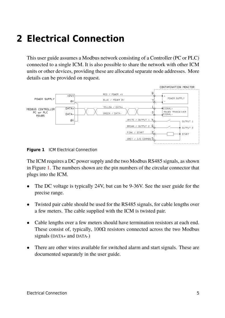
Figure 1 ICM Electrical Connection
The ICM requires a DC power supply and the two Modbus RS485 signals, as shownin Figure 1. The numbers shown are the pin numbers of the circular connector thatplugs into the ICM.
• The DC voltage is typically 24V, but can be 9-36V. See the user guide for theprecise range.
• Twisted pair cable should be used for the RS485 signals, for cable lengths overa few meters. The cable supplied with the ICM is twisted pair.
• Cable lengths over a few meters should have termination resistors at each end.These consist of, typically, 100Ω resistors connected across the two Modbussignals (DATA+ and DATA-)
• There are other wires available for switched alarm and start signals. These aredocumented separately in the user guide.
6 Modbus Operations
3 Modbus Operations
3.1 Modbus Settings
Protocol type RTU (not ASCII)Data Bits 8Stop Bits 1Parity Required, EvenBaud Auto-sensing 1200-115200Signalling RS485Node Address 17 (or user set)
3.2 Communications Check
You should be able to read the product ID code from register 0 (from Modbusnode address 204). The product ID code is the value 54237 (decimal) or 0xD3DD(hexadecimal)
3.3 Result Format
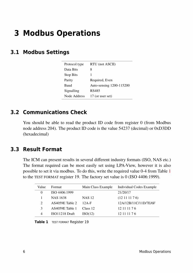
The ICM can present results in several different industry formats (ISO, NAS etc.)The format required can be most easily set using LPA-View, however it is alsopossible to set it via modbus. To do this, write the required value 0-4 from Table 1to the TEST FORMAT register 19. The factory set value is 0 (ISO 4406:1999).
Value Format Main Class Example Individual Codes Example0 ISO 4406:1999 21/20/171 NAS 1638 NAS 12 (12 11 11 7 6)2 AS4059E Table 2 12A-F 12A/12B/11C/11D/7E/6F3 AS4059E Table 1 Class 12 12 11 11 7 64 ISO11218 Draft ISO(12) 12 11 11 7 6
Table 1 TEST FORMAT Register 19
Modbus Operations 7
3.4 Result Codes
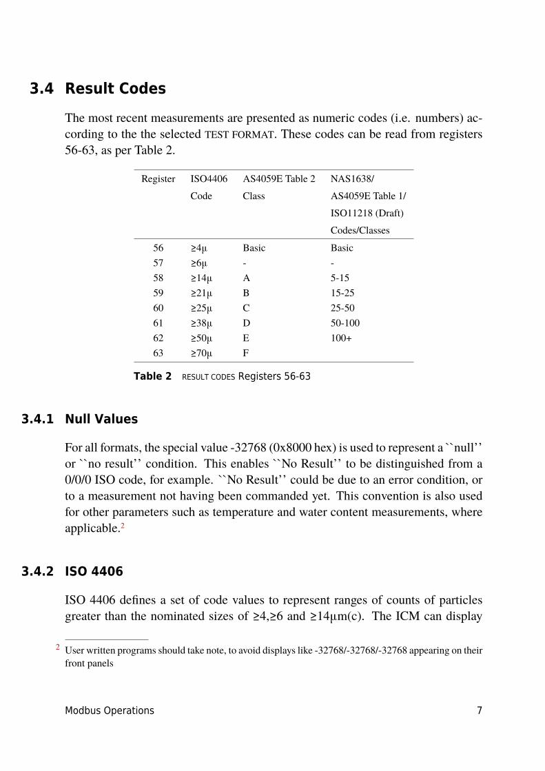
The most recent measurements are presented as numeric codes (i.e. numbers) ac-cording to the the selected TEST FORMAT. These codes can be read from registers56-63, as per Table 2.
Register ISO4406 AS4059E Table 2 NAS1638/
Code Class AS4059E Table 1/
ISO11218 (Draft)
Codes/Classes
56 ≥4μ Basic Basic57 ≥6μ - -58 ≥14μ A 5-1559 ≥21μ B 15-2560 ≥25μ C 25-5061 ≥38μ D 50-10062 ≥50μ E 100+63 ≥70μ F
Table 2 RESULT CODES Registers 56-63
3.4.1 Null Values
For all formats, the special value -32768 (0x8000 hex) is used to represent a ``null’’or ``no result’’ condition. This enables ``No Result’’ to be distinguished from a0/0/0 ISO code, for example. ``No Result’’ could be due to an error condition, orto a measurement not having been commanded yet. This convention is also usedfor other parameters such as temperature and water content measurements, whereapplicable.2
3.4.2 ISO 4406
ISO 4406 defines a set of code values to represent ranges of counts of particlesgreater than the nominated sizes of ≥4,≥6 and ≥14μm(c). The ICM can display
2 User written programs should take note, to avoid displays like -32768/-32768/-32768 appearing on theirfront panels

8 Modbus Operations
codes from 0 to 24. The three-part code is available in the first 3 RESULT CODES.We additionally make available equivalent codes for the other sizes from 21 to68μm(c), as per Table 2.
3.4.3 NAS1638 / AS4059E-1 / ISO11218
These assign code numbers for the particle counts in each size range shown in thetable. The ``basic’’ class is then the highest of these individual codes. The basicclass is in the first register, with the individual classes made available in the registersshown.
For these standards there is a complication in that they all define an additionalclass ``00’’. This is an extra ``cleaner than class 0’’ class. We distinguish thisfrom 0 using the numeric value -1. Negative numbers are represented in a Modbusregister using the ``twos complement’’ notation. If the user program interprets thisas a positive number it will appear as 65535 (0xFFFF hex).
Classes range from 00(-1) to 12.
3.4.4 AS4059E-2
AS4059E Table 2 also has some similarities to NAS1638. In terms of the represen-tation in Modbus registers, the main differences are an extra 4-6μm(c) size rangeand the addition of an extra ``000’’ class. This is represented using the number-2. If the user program interprets this as a positive number it will appear as 65534(0xFFFE hex).
3.5 Temperature and Water Content Measurements
These are contained in the TEMPERATURE register 33 and the RH (relative humid-ity) register 34. These are scaled by a factor of 100, so that values of 12.34°C and56.78% RH would be represented by values of 1234 and 5678 respectively. Thetemperature can go negative, in which case the usual ``twos complement’’ rep-resentation is used. Most controllers should have a facility for reading ``signedintegers’’ encoded in this way.3
3 These will appear as large positive numbers if interpreted instead as positive numbers, for example65535.
Modbus Operations 9
The special value -32768 (0x8000 hex) is again used to indicate ``No result’’, asper the contamination result codes. This could be due to a sensor failure or to theunit still in the process of powering up.
3.6 Commanding Test Start
If the ICM is monitoring a single machine, it will normally be configured to testcontinuously and automatically, so that the contamination measurement can be readout at any time as described above. However some applications need a defined teststart and test end, for example end-of-line production testing, where each resultrelates to a separate item being tested.
These applications can simply use a push button (or relay) wired to the ICM startsignal, or the front panel push button, or can be commanded programmatically viaModbus.
To start or restart a test, write the value 1 to the command register 21. The testduration can be set using LPA-View before installation, or alternatively write therequired test time (in seconds) to the TEST DURATION register 18.
3.7 Test Status
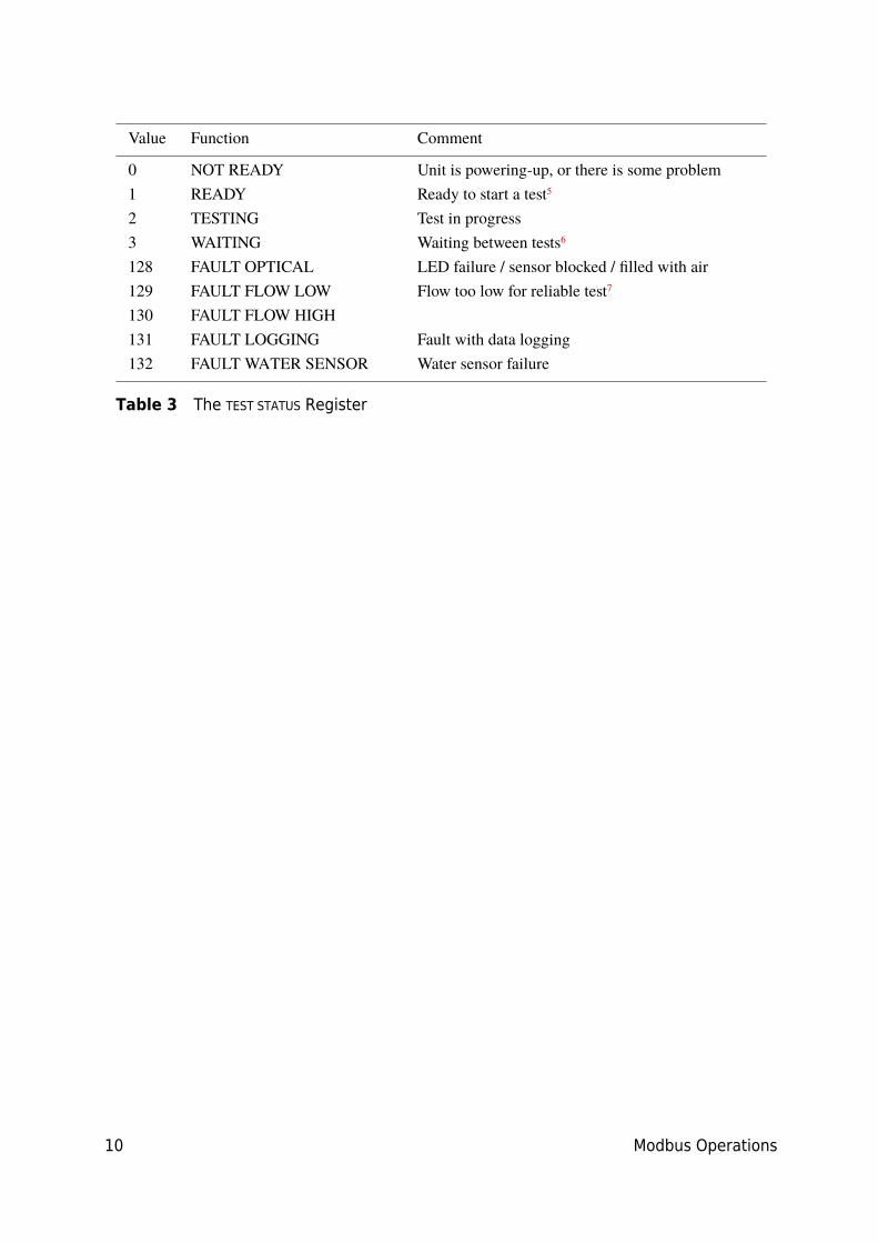
A test status code is available in register 30. This contains a number indicatingthe current state of the ICM, according to Table 3. This allows a system to remotelymonitor the ICM operation, if desired, allowing more specific diagnostics.4
4 However the fault conditions are also indicated on the front panel LED, while ``No Result’’ in the caseof a fault is indicated using special result values as previously described.
5 User has not set tests to occur automatically.6 User has set a non-zero test interval.7 Or fluid is totally clean (no particle counts). Flow alarm can be turned off by user if this is a problem,
for example cleaning rigs.
10 Modbus Operations
Value Function Comment
0 NOT READY Unit is powering-up, or there is some problem1 READY Ready to start a test5
2 TESTING Test in progress3 WAITING Waiting between tests6
128 FAULT OPTICAL LED failure / sensor blocked / filled with air129 FAULT FLOW LOW Flow too low for reliable test7
130 FAULT FLOW HIGH131 FAULT LOGGING Fault with data logging132 FAULT WATER SENSOR Water sensor failure
Table 3 The TEST STATUS Register
Modbus Operations 11
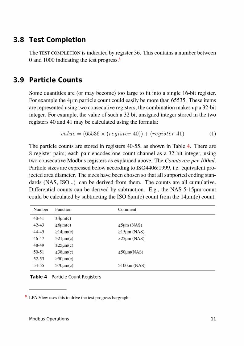
3.8 Test Completion
The TEST COMPLETION is indicated by register 36. This contains a number between0 and 1000 indicating the test progress.8
3.9 Particle Counts
Some quantities are (or may become) too large to fit into a single 16-bit register.For example the 4μm particle count could easily be more than 65535. These itemsare represented using two consecutive registers; the combination makes up a 32-bitinteger. For example, the value of such a 32 bit unsigned integer stored in the tworegisters 40 and 41 may be calculated using the formula:
𝑣𝑎𝑙𝑢𝑒 = (65536 × (𝑟𝑒𝑔𝑖𝑠𝑡𝑒𝑟 40)) + (𝑟𝑒𝑔𝑖𝑠𝑡𝑒𝑟 41) (1)
The particle counts are stored in registers 40-55, as shown in Table 4. There are8 register pairs; each pair encodes one count channel as a 32 bit integer, usingtwo consecutive Modbus registers as explained above. The Counts are per 100ml.Particle sizes are expressed below according to ISO4406:1999, i.e. equivalent pro-jected area diameter. The sizes have been chosen so that all supported coding stan-dards (NAS, ISO...) can be derived from them. The counts are all cumulative.Differential counts can be derived by subtraction. E.g., the NAS 5-15µm countcould be calculated by subtracting the ISO 6µm(c) count from the 14µm(c) count.
Number Function Comment
40-41 ≥4µm(c)42-43 ≥6µm(c) ≥5µm (NAS)44-45 ≥14µm(c) ≥15µm (NAS)46-47 ≥21µm(c) >25µm (NAS)48-49 ≥25µm(c)50-51 ≥38µm(c) ≥50µm(NAS)52-53 ≥50µm(c)54-55 ≥70µm(c) ≥100µm(NAS)
Table 4 Particle Count Registers
8 LPA-View uses this to drive the test progress bargraph.

12 Modbus Operations

Appendix A
Reference 13
Reference
Modbus Node Addressing
Modbus requests are sent to the configured ICM node address. If there is only oneICM on network segment, then the ``Permanent Address’’ of 204 can be used.IX Ifthere is more than one, then unique node addresses must be configured for each.
Modbus Settings
Protocol type RTU (not ASCII)Baud Auto-sensing 1200-115200Parity EvenSignalling RS485Node Address Factory set to 17. User settable 1-254.Permanent Address 204
General Description
The ICM is a Modbus Slave. That is, it responds only to commands sent to it by theModbus controller (the Modbus Master). The controller can be a program runningon a PC, or a PLC.
The Master periodically sends a Modbus command ``frame’’ to the ICM node ad-dress. The ICM acknowledges each request with a response frame.
Modbus Registers
The Modbus protocol defines many types of information interchange commands(``function codes’’). However in order to simplify implementation the ICM only
IX This is not part of the Modbus specification (and in fact violates it). The ICM will always respondon node address 204, in addition to the other set value. This was done so that LPA-View can connectdirectly without configuration or scanning of the network.

Appendix A
14 Reference
uses one type - the Modbus ``Register’’. Conceptually the ICM appears as a collec-tion of Modbus Registers. Each register is numbered - the ICM has 125 registers.Each register holds a number representing some quantity. For example, registernumber 2 holds a number indicating the ICM software revision.
Modbus Register Numbering
Addresses shown here are those appearing ``on the wire’’. Unfortunately someModbus controllers may translate these addresses to different ones. For examplefor some controllers the user will need to use ``addresses’’ starting at 40000 insteadof 0.
The ICM uses the registers from 0-124.X. Registers can be divided into classes asfollows.
Status Registers
These are ``read-only’’ registers that indicate test results and ICM status. They canbe read freely at any time (although test results are only valid after a successfultest).
Setting Registers
These are read-write registers used to hold the ICM settings. Take care not toinadvertently write to any of these registers since the ICM settings will be altered!
Some ``Setting’’ registers also change by themselves, for example the test numberregister can be set, but will also automatically increment after each test.
Calibration Registers
Some registers, not documented here, are protected settings that can only be alteredduring factory calibration.
X This allows all registers to fit in a single Modbus frame
Appendix A
Reference 15
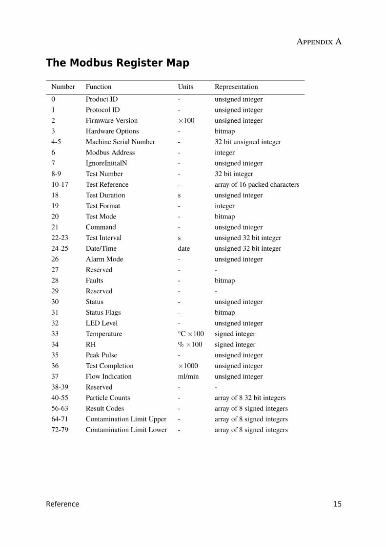
The Modbus Register Map
Number Function Units Representation
0 Product ID - unsigned integer1 Protocol ID - unsigned integer2 Firmware Version ×100 unsigned integer3 Hardware Options - bitmap4-5 Machine Serial Number - 32 bit unsigned integer6 Modbus Address - integer7 IgnoreInitialN - unsigned integer8-9 Test Number - 32 bit integer10-17 Test Reference - array of 16 packed characters18 Test Duration s unsigned integer19 Test Format - integer20 Test Mode - bitmap21 Command - unsigned integer22-23 Test Interval s unsigned 32 bit integer24-25 Date/Time date unsigned 32 bit integer26 Alarm Mode - unsigned integer27 Reserved - -28 Faults - bitmap29 Reserved - -30 Status - unsigned integer31 Status Flags - bitmap32 LED Level - unsigned integer33 Temperature °C ×100 signed integer34 RH % ×100 signed integer35 Peak Pulse - unsigned integer36 Test Completion ×1000 unsigned integer37 Flow Indication ml/min unsigned integer38-39 Reserved - -40-55 Particle Counts - array of 8 32 bit integers56-63 Result Codes - array of 8 signed integers64-71 Contamination Limit Upper - array of 8 signed integers72-79 Contamination Limit Lower - array of 8 signed integers
Appendix A
16 Reference
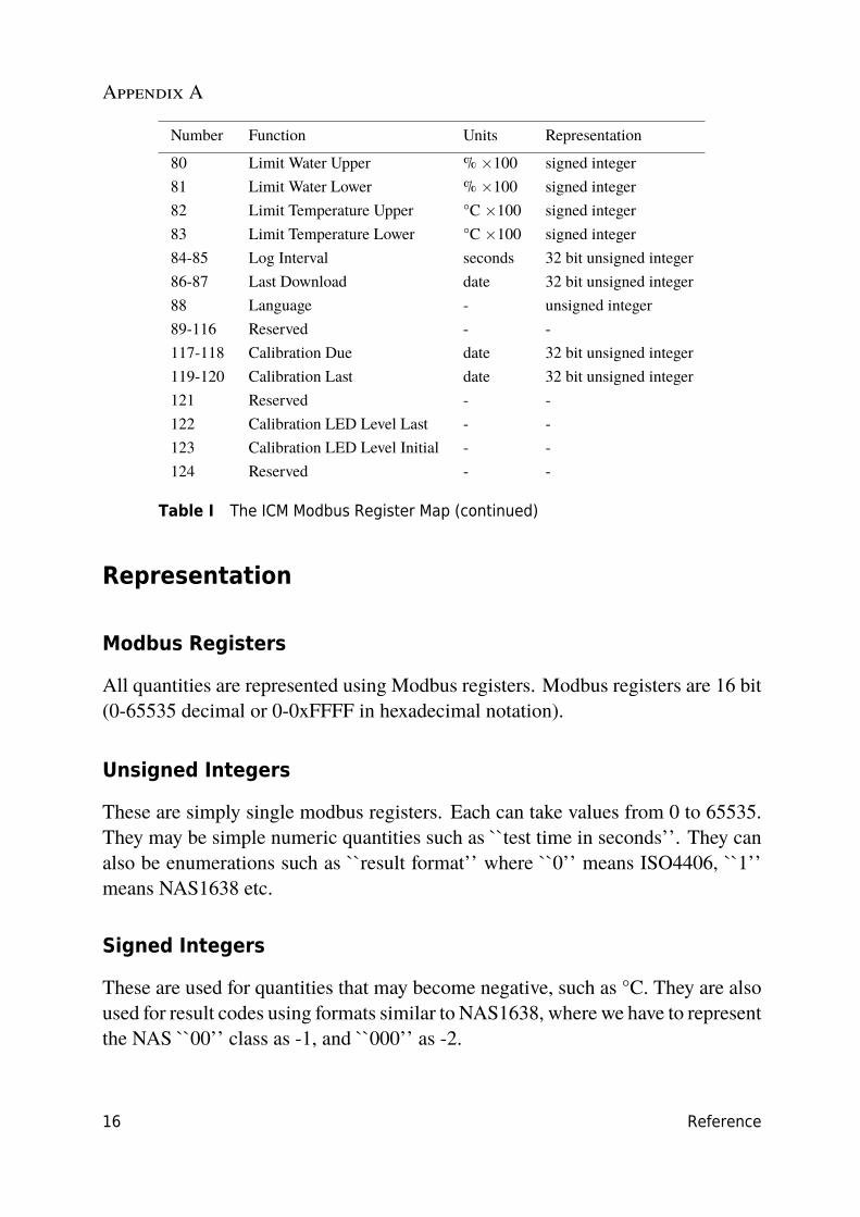
Number Function Units Representation
80 Limit Water Upper % ×100 signed integer81 Limit Water Lower % ×100 signed integer82 Limit Temperature Upper °C ×100 signed integer83 Limit Temperature Lower °C ×100 signed integer84-85 Log Interval seconds 32 bit unsigned integer86-87 Last Download date 32 bit unsigned integer88 Language - unsigned integer89-116 Reserved - -117-118 Calibration Due date 32 bit unsigned integer119-120 Calibration Last date 32 bit unsigned integer121 Reserved - -122 Calibration LED Level Last - -123 Calibration LED Level Initial - -124 Reserved - -
Table I The ICM Modbus Register Map (continued)
Representation
Modbus Registers
All quantities are represented using Modbus registers. Modbus registers are 16 bit(0-65535 decimal or 0-0xFFFF in hexadecimal notation).
Unsigned Integers
These are simply single modbus registers. Each can take values from 0 to 65535.They may be simple numeric quantities such as ``test time in seconds’’. They canalso be enumerations such as ``result format’’ where ``0’’ means ISO4406, ``1’’means NAS1638 etc.
Signed Integers
These are used for quantities that may become negative, such as °C. They are alsoused for result codes using formats similar to NAS1638, where we have to representthe NAS ``00’’ class as -1, and ``000’’ as -2.

Appendix A
Reference 17
Signed integers are represented in single modbus registers using the ``twos com-plement’’ standard, as usual in computing. If a user-written program incorrectlyinterprets a signed integer as unsigned, then positive numbers will still be inter-preted correctly. However small negative numbers will appear as large positiveones. In particular, -1 appears as 65535 and -2 as 65534. These might be seenwhen interpreting the NAS codes mentioned above. Take care when writing soft-ware dealing with NAS codes or Temperature measurements.
32 Bit Unsigned Integers
Some quantities are (or may become) too large to fit into a single 16-bit register. Forexample the Test Number could eventually increment to more than 65535. Theseitems are represented using two consecutive registers; the combination makes upa 32-bit integer. For example, the value of such a 32 bit unsigned integer stored inregisters 8-9 may be calculated using the formula:
𝑣𝑎𝑙𝑢𝑒 = (65536 × (𝑟𝑒𝑔𝑖𝑠𝑡𝑒𝑟 8)) + (𝑟𝑒𝑔𝑖𝑠𝑡𝑒𝑟 9) (1)
Bitmaps
Bitmaps are again single 16-bit Modbus registers, but they have a special inter-pretation. Each ``bit’’ in the register has a separate function. The most importantexample is the ``status flags’’ register (31). Each register bit encodes a separatefunction, for example ``result valid’’, ``new result’’, ``over temperature alarm’’etc. In this document bits are numbered starting with bit 0 = least significant bit.
A user programming environment such as a PLC programming system or a highlevel computer language will normally have functions that allow easy access ofindividual bit values in a register.
Arrays
An Array is simply a sequence of objects packed in consecutive registers. Forexample the ``result codes’’ are in an array of 8 registers. Code[0] is in register 56,code[1] is in register 57 etc.
Appendix A
18 Reference
In the case of an array of 32-bit integers, each element itself takes up 2 registers,so there are are twice as many registers used as elements in the array. In the caseof the particle counts array, there are 8 particle sizes counted so these are stored in8 × 2 = 16 registers.
Packed Characters
These are used to encode the user-settable ``test reference’’ string, used to labeleach test. Characters are packed two per Modbus register. This will probably notbe used in a user-written Modbus program, but in principle the test reference couldbe set to a different value for each test. The test reference string consists of of 16characters packed into an array of 8 consecutive registers.
Date/Time
A ``Date’’ represents a calendar date and time as a 32 bit unsigned integer (it isthe number of seconds since Jan 1 1970). User programs will not generally have todeal with this, but in principle they could e.g. read or set the real time clock fromregisters 24-25. It can be useful during development to be able to read the clockand see a continuously incrementing value of seconds.
Register Functions
Test Mode
Factory set value: 0
This is the "test mode", each bit represents an option corresponding to a tickbox onthe ICM settings screen (see our LPA-View software and in the ICM manual).
Each bit of the register encodes one tickbox.
The factory set mode is 0 for all bits, so all the tickboxes are turned off. You maywant to turn on bit 8 (disable low flow alarm when clean) if you have a very cleansystem.
Here are the bit definitions:
Appendix A
Reference 19
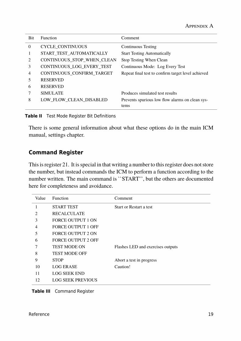
Bit Function Comment
0 CYCLE_CONTINUOUS Continuous Testing1 START_TEST_AUTOMATICALLY Start Testing Automatically2 CONTINUOUS_STOP_WHEN_CLEAN Stop Testing When Clean3 CONTINUOUS_LOG_EVERY_TEST Continuous Mode: Log Every Test4 CONTINUOUS_CONFIRM_TARGET Repeat final test to confirm target level achieved5 RESERVED6 RESERVED7 SIMULATE Produces simulated test results8 LOW_FLOW_CLEAN_DISABLED Prevents spurious low flow alarms on clean sys-
tems
Table II Test Mode Register Bit Definitions
There is some general information about what these options do in the main ICMmanual, settings chapter.
Command Register
This is register 21. It is special in that writing a number to this register does not storethe number, but instead commands the ICM to perform a function according to thenumber written. The main command is ``START’’, but the others are documentedhere for completeness and avoidance.
Value Function Comment
1 START TEST Start or Restart a test2 RECALCULATE3 FORCE OUTPUT 1 ON4 FORCE OUTPUT 1 OFF5 FORCE OUTPUT 2 ON6 FORCE OUTPUT 2 OFF7 TEST MODE ON Flashes LED and exercises outputs8 TEST MODE OFF9 STOP Abort a test in progress10 LOG ERASE Caution!11 LOG SEEK END12 LOG SEEK PREVIOUS
Table III Command Register
Appendix A
20 Reference
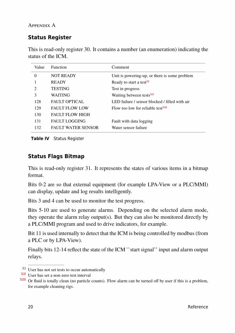
Status Register
This is read-only register 30. It contains a number (an enumeration) indicating thestatus of the ICM.
Value Function Comment
0 NOT READY Unit is powering-up, or there is some problem1 READY Ready to start a testXI
2 TESTING Test in progress3 WAITING Waiting between testsXII
128 FAULT OPTICAL LED failure / sensor blocked / filled with air129 FAULT FLOW LOW Flow too low for reliable testXIII
130 FAULT FLOW HIGH131 FAULT LOGGING Fault with data logging132 FAULT WATER SENSOR Water sensor failure
Table IV Status Register
Status Flags Bitmap
This is read-only register 31. It represents the states of various items in a bitmapformat.
Bits 0-2 are so that external equipment (for example LPA-View or a PLC/MMI)can display, update and log results intelligently.
Bits 3 and 4 can be used to monitor the test progress.
Bits 5-10 are used to generate alarms. Depending on the selected alarm mode,they operate the alarm relay output(s). But they can also be monitored directly bya PLC/MMI program and used to drive indicators, for example.
Bit 11 is used internally to detect that the ICM is being controlled by modbus (froma PLC or by LPA-View).
Finally bits 12-14 reflect the state of the ICM ``start signal’’ input and alarm outputrelays.
XI User has not set tests to occur automaticallyXII User has set a non-zero test interval
XIII Or fluid is totally clean (no particle counts). Flow alarm can be turned off by user if this is a problem,for example cleaning rigs.
Appendix A
Reference 21
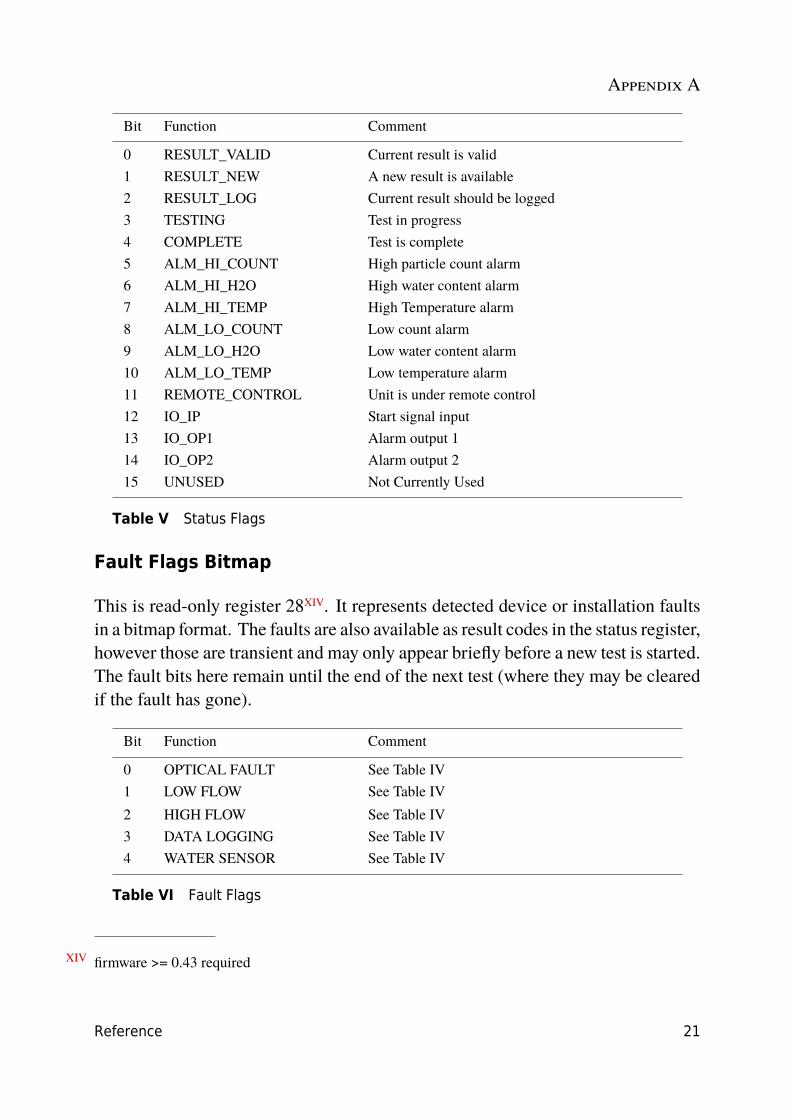
Bit Function Comment
0 RESULT_VALID Current result is valid1 RESULT_NEW A new result is available2 RESULT_LOG Current result should be logged3 TESTING Test in progress4 COMPLETE Test is complete5 ALM_HI_COUNT High particle count alarm6 ALM_HI_H2O High water content alarm7 ALM_HI_TEMP High Temperature alarm8 ALM_LO_COUNT Low count alarm9 ALM_LO_H2O Low water content alarm10 ALM_LO_TEMP Low temperature alarm11 REMOTE_CONTROL Unit is under remote control12 IO_IP Start signal input13 IO_OP1 Alarm output 114 IO_OP2 Alarm output 215 UNUSED Not Currently Used
Table V Status Flags
Fault Flags Bitmap
This is read-only register 28XIV. It represents detected device or installation faultsin a bitmap format. The faults are also available as result codes in the status register,however those are transient and may only appear briefly before a new test is started.The fault bits here remain until the end of the next test (where they may be clearedif the fault has gone).
Bit Function Comment
0 OPTICAL FAULT See Table IV1 LOW FLOW See Table IV2 HIGH FLOW See Table IV3 DATA LOGGING See Table IV4 WATER SENSOR See Table IV
Table VI Fault Flags
XIV firmware >= 0.43 required

Appendix A
22 Reference
Particle Counts
These use registers 40-55. There are 8 register pairs; each pair encodes one countchannel as a 32 bit integer. Counts are per 100ml. Particle sizes are expressed be-low according to ISO4406:1999, i.e. equivalent projected area diameter. The sizeshave been chosen so that all supported coding standards (NAS, ISO...) can be de-rived from them. The counts are all cumulative. Differential counts can be derivedby subtraction. E.g., the NAS 5-15µm count could be calculated by subtracting the``ISO’’ 6µm(c) count from the 14µm(c) count.
Number Function Comment
40-41 ≥4µm(c)42-43 ≥6µm(c) ≥5µm (NAS)44-45 ≥14µm(c) ≥15µm (NAS)46-47 ≥21µm(c) >25µm (NAS)48-49 ≥25µm(c)50-51 ≥38µm(c) ≥50µm(NAS)52-53 ≥50µm(c)54-55 ≥70µm(c) ≥100µm(NAS)
Table VII Particle Counts
Result Format
The ICM supports all major standards for the coding of particulate contamination.The coding standard is selected by writing to register 19 ``Test Format’’. This isa number (enumeration) indicating the format required. It can be set by the userfrom LPA-View or programmatically over Modbus.
The selected format does not affect the particle count values, but does completelychange the interpretation of the result codes and set limits, if used.
Note: If the format is changed, then any set alarm limits must be changed too sincethese will refer to the old format. E.g. a limit of ``NAS 11’’ cannot be directlyexpressed using the ISO4406 standard.
Appendix A
Reference 23
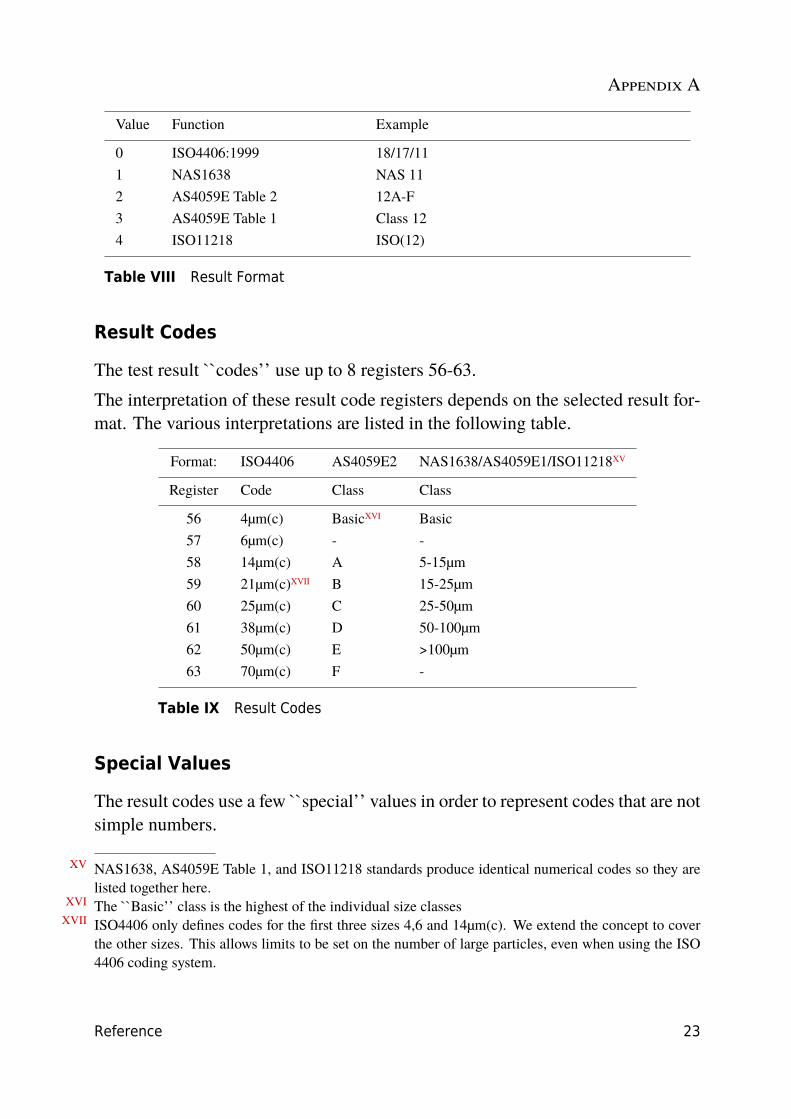
Value Function Example
0 ISO4406:1999 18/17/111 NAS1638 NAS 112 AS4059E Table 2 12A-F3 AS4059E Table 1 Class 124 ISO11218 ISO(12)
Table VIII Result Format
Result Codes
The test result ``codes’’ use up to 8 registers 56-63.The interpretation of these result code registers depends on the selected result for-mat. The various interpretations are listed in the following table.
Format: ISO4406 AS4059E2 NAS1638/AS4059E1/ISO11218XV
Register Code Class Class
56 4µm(c) BasicXVI Basic57 6µm(c) - -58 14µm(c) A 5-15µm59 21µm(c)XVII B 15-25µm60 25µm(c) C 25-50µm61 38µm(c) D 50-100µm62 50µm(c) E >100µm63 70µm(c) F -
Table IX Result Codes
Special Values
The result codes use a few ``special’’ values in order to represent codes that are notsimple numbers.
XV NAS1638, AS4059E Table 1, and ISO11218 standards produce identical numerical codes so they arelisted together here.
XVI The ``Basic’’ class is the highest of the individual size classesXVII ISO4406 only defines codes for the first three sizes 4,6 and 14µm(c). We extend the concept to cover
the other sizes. This allows limits to be set on the number of large particles, even when using the ISO4406 coding system.
Appendix A
24 Reference
The NAS1638 standard defines classes ``00’’ and ``000’’, these are classes ``cleaner’’than class 0. We represent these using signed integers of value -1 and -2 respec-tively.XVIII
Alarm Mode
The ICM includes two relay outputs that can optionally be used for signaling thestate of the unit. These are normally used in ``stand-alone’’ applications where themodbus interface is not used (since a modbus controller / PLC already has all theexact results available in digital form and can work with these directly.)
There are a number of preset ``modes’’ that determine the exact function of therelays. Refer to the ICM-R user guide for more details (in the section Settings /Alarms / Alarm Mode).
These modes are normally set at installation time using our PC software packageLPA-View. But it is also possible to use modbus to set the operating mode of theserelays, by writing the corresponding integer to the alarm mode register 26.
Alarm Limits
Settable Upper and Lower limits for particulate contamination are provided.
These are two groups of 8 registers representing the ``Upper Limit’’ and ``LowerLimit’’ for particulate contamination. These are 64-71 and 72-79 respectively.
These are expressed in terms of the result codes using the same format as in 3.4. Anadditional special value of 0x8000 (hexadecimal representation) is used to signifya ``don’t care’’ setting for that limit code.
XVIII These will appear as 65535 and 63334 if read as unsigned integers as discussed in
Appendix B
Implementing Modbus 25
Implementing Modbus
This section is for advanced users who wish to do their own programming to im-plement the modbus controller. It is not needed if the users control system alreadyhas direct support for being a modbus master. The following describes a minimalsystem capable of periodically reading data from the ICM, it is not intended as ageneral purpose modbus implementation.
For a background to this section the implementor can review the modbus sourcedocuments:
http://www.modbus.org/docs/Modbus_over_serial_line_V1.pdf
http://www.modbus.org/docs/Modbus_Application_Protocol_V1_1b.pdf
In order to collect data from the ICM, the users control system needs to be ableto send a modbus command frame and receive a response frame via the RS485signals.
A frame consists of a sequence of bytes, transmitted back-to-back over the RS485interface.
A command frame can be generated corresponding to a modbus ``read registers’’command. Using hexadecimal notation, the sequence required to return all regis-ters would be a sequence of 8 bytes:
<0xCC> <0x04> <0x00> <0x00> <0x00> <0x7D> <0x20> <0x36>
This sequence is decoded by the ICM as:
<0xCC> = <slave address><0x04> = <function code:read registers><0x00> <0x00> = <start register high> <start register low> (2 bytes)<0x00> <0x7D> = <number of registers high> <number of registers low> (2 bytes)<0x20> <0x36> = <checksum high> <checksum low> (2 bytes)
The ICM will then return a 255 byte long response frame containing the requestedregister contents.
This 255 byte response frame looks like:
<0xCC> <0x04> <0xfa> <250 bytes of data> <2 bytes of checksum>

Appendix B
26 Implementing Modbus
The <250 bytes of data> contains the contents of the 125 registers requested. Each16 bit register is encoded in two sequential bytes, in high-low (``big-endian’’) order.
The simplest method is then to read the required registers directly out of the dataarea of this response frame. For example, the ICM product ID code appears inmodbus register 0. This would therefore appear in the first two bytes of the dataarea above, or at the 4th and 5th bytes counting from the start of the frame. In aprogramming language like ``C’’ the product ID could be extracted from an arraycontaining the frame using a statement like:
unsigned product_id = 256*buf[3+0] + buf[3+1];
Users of PLCs or other programming languages will hopefully be able to translateusing the information provided here.
The ICM product ID is 0xD3DD (hexadecimal) or 54237 (decimal). This fact canbe used as a check when attempting the above implementation.
Finally we come to extracting the test result. Referring to the ICM modbus registermap, the test result codes appear in registers 56-63. In the case of NAS1638, theoverall NAS code is in register 56. So a program can extract the overall NAS codefrom the result frame using logic equivalent to the ``C’’ language expression:
unsigned NAS = 256*buf[3 + 56*2 + 0] + buf[3 + 56*2 + 1]
This is a statement in the ``C’’ programming language that reads the 116th and117th bytes of the response frame, and forms a 16 bit number from these two 8 bitbytes. This reads modbus register 56, the NAS code.
Similar expressions can be used to read the other registers according to the datarequired.
For PLC users the details will be dependent on their own programming environ-ment and facilities. But hopefully the above can be used as a guide for their ownimplementation,

Produced by MP Filtri UK
Revision 0.32
As a policy of continual improvement, MP Filtri UK reserve the right to alter specificationswithout prior notice.
Except as permitted by such licence, no part of this publication may be reproduced, stored inretrieval system or transmitted, in any form or any means, electronic, mechanical, recording, orotherwise, without prior written permission of MP Filtri UK.

![u[sonic] Modbus - Lambrecht meteo](https://static.fdokumen.com/doc/165x107/6334bd04a6138719eb0b33dc/usonic-modbus-lambrecht-meteo.jpg)