FCR015 modbus - NET
18
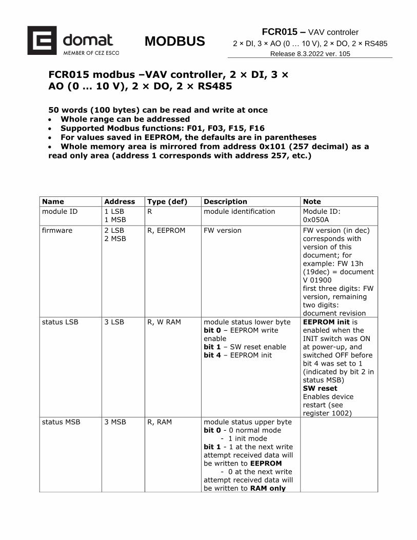
MODBUS FCR015 – VAV controler 2 × DI, 3 × AO (0 … 10 V), 2 × DO, 2 × RS485 Release 8.3.2022 ver. 105 FCR015 modbus –VAV controller, 2 × DI, 3 × AO (0 … 10 V), 2 × DO, 2 × RS485 50 words (100 bytes) can be read and write at once • Whole range can be addressed • Supported Modbus functions: F01, F03, F15, F16 • For values saved in EEPROM, the defaults are in parentheses • Whole memory area is mirrored from address 0x101 (257 decimal) as a read only area (address 1 corresponds with address 257, etc.) Name Address Type (def) Description Note module ID 1 LSB 1 MSB R module identification Module ID: 0x050A firmware 2 LSB 2 MSB R, EEPROM FW version FW version (in dec) corresponds with version of this document; for example: FW 13h (19dec) = document V 01900 first three digits: FW version, remaining two digits: document revision status LSB 3 LSB R, W RAM module status lower byte bit 0 – EEPROM write enable bit 1 – SW reset enable bit 4 – EEPROM init EEPROM init is enabled when the INIT switch was ON at power-up, and switched OFF before bit 4 was set to 1 (indicated by bit 2 in status MSB) SW reset Enables device restart (see register 1002) status MSB 3 MSB R, RAM module status upper byte bit 0 - 0 normal mode - 1 init mode bit 1 - 1 at the next write attempt received data will be written to EEPROM - 0 at the next write attempt received data will be written to RAM only
-
Upload
khangminh22 -
Category
Documents
-
view
0 -
download
0
Transcript of FCR015 modbus - NET
MODBUS FCR015 – VAV controler
2 × DI, 3 × AO (0 … 10 V), 2 × DO, 2 × RS485
Release 8.3.2022 ver. 105
FCR015 modbus –VAV controller, 2 × DI, 3 × AO (0 … 10 V), 2 × DO, 2 × RS485 50 words (100 bytes) can be read and write at once
• Whole range can be addressed • Supported Modbus functions: F01, F03, F15, F16 • For values saved in EEPROM, the defaults are in parentheses
• Whole memory area is mirrored from address 0x101 (257 decimal) as a read only area (address 1 corresponds with address 257, etc.)
Name Address Type (def) Description Note
module ID 1 LSB
1 MSB
R module identification Module ID:
0x050A
firmware 2 LSB
2 MSB
R, EEPROM FW version FW version (in dec)
corresponds with
version of this
document; for
example: FW 13h
(19dec) = document
V 01900
first three digits: FW
version, remaining
two digits:
document revision
status LSB 3 LSB R, W RAM module status lower byte
bit 0 – EEPROM write
enable
bit 1 – SW reset enable
bit 4 – EEPROM init
EEPROM init is
enabled when the
INIT switch was ON
at power-up, and
switched OFF before
bit 4 was set to 1
(indicated by bit 2 in
status MSB)
SW reset
Enables device
restart (see
register 1002)
status MSB 3 MSB R, RAM module status upper byte
bit 0 - 0 normal mode
- 1 init mode
bit 1 - 1 at the next write
attempt received data will
be written to EEPROM
- 0 at the next write
attempt received data will
be written to RAM only

MODBUS FCR015 – VAV controler
2 × DI, 3 × AO (0 … 10 V), 2 × DO, 2 × RS485
Release 8.3.2022 ver. 105
bit 2 – 1 EEPROM
initialised
bit 3 – not used
bit 4 – 0
bit 5 – SW reset enable
bit 6 – 0
bit 7 – commision mode
(1)
address 4 LSB R, W EEPROM
(0x01)
module address
(for even distribution of
load, fans and
outputs will enable after
time equal to address
mod 10)
!!! The changes will
become active only
after module restart
(the register is
written immediately,
but the new address
is effective after
restart)
baud rate 4 MSB R, W EEPROM
(9600 bps, 13
dec)
communication, no parity
10dec … 1 200bps
11dec … 2 400bps
12dec … 4 800bps
13dec … 9 600bps
14dec … 19 200bps
15dec … 38 400bps
16dec … 57 600bps
17dec … 115 200bps
!!! The changes will
become active only
after module restart
(the register is
written immediately,
but the new baud
rate is effective after
restart)
serial port
setting
5 LSB R, W EEPROM
(no parity,
one stopbit,
0x00)
serial port settings
bit 0-1 – parity
- 00 – no parity
- 01 – even,
- 10 – odd
bit 2 … number of stopbits
- 0 … one
- 1 … two
!!! The changes will
become active only
after module restart
5 MSB reserved
eeprom writes 6 LSB
6 MSB
R, EEPROM number of EEPROM writes no overflow,
EEPROM init not
reset this register
relay 7 LSB R, RAM state of relay outputs
(D01, D02)
bit 0 … relay 1
bit 1 … relay 2
inputs 7 MSB R, RAM digital inputs status (DI1
... presence, DI2 ...
window contact) and
heating/cooling demands;
DI1 and DI2 state – logical
(active/inactive) or
physical state (voltage
on/voltage off) - takes into
accout settings from
inputs settings register,
bit 0 … input DI1
bit 1 … input DI2
bit 2 … heating
demand (PID output
HEAT > 5%)
bit 3 … cooling
demand (PID output
COOL > 5%)

MODBUS FCR015 – VAV controler
2 × DI, 3 × AO (0 … 10 V), 2 × DO, 2 × RS485
Release 8.3.2022 ver. 105
if system includes slave
modules, they are already
included in that register.
The master controller
inputs must be enabled
(see inputs settings) to
include slave module
inputs.
Pid output HEAT 8 LSB R, RAM controller heating output
(PID output)
range 0 … 100 %
Pid output COOL 8 MSB R, RAM controller cooling output
(PID output, icl. manual
control value, incl. change-
over C/O mode)
range 0 … 100 %
P output VAV 9 LSB R, RAM output of P CO2 regulation
for VAV box, if in manual
control value is 30-70-100
% according to chosen fan
speed
range 0 … 100 %
UC
communication
state
9 MSB R, RAM state of communication
with UC010
(timeout = 3 secs)
0 … comm ok
1 … timeout
2 … MB exception
3 … MB error
Manual control 10 LSB R, W RAM manual output control and
changeover (C/O, for
changeover delay switch
see reg. 43MSB), if
corresponding bit is set to
1, then output value is set
from manual values (see
manual fan speed,
manual heat output,
manual cool output),
otherwise controller values
are taken;
for other DO output
settings see reg. 141;
C/O -> output of cooling
sequence will be used for
heating output
bit 0 … AO3 VAV
bit 1 … AO1 heat
output
bit 2 … AO2 cool
output
bit 3 … DO1 state
(if bit 0 of register
141 = 0)
bit 4 … DO2 state
(if bit 1 of register
141 = 0)
bit 5 … C/O (1 - ON)
Manual VAV
(AO3)
10 MSB R, W RAM manual settings of fan
speed AO3 (only if
corresponding bit is set in
reg. manual control); AO
may include also output
min/max transformation
range 0 … 100 %
Manual heat
output (AO1)
11 LSB R, W RAM manual settings of heating
output AO1 (only if
corresponding bit is set in
reg. manual control); AO
range 0 … 100 %
MODBUS FCR015 – VAV controler
2 × DI, 3 × AO (0 … 10 V), 2 × DO, 2 × RS485
Release 8.3.2022 ver. 105
may include also output
min/max transformation
Manual cool
output (AO2)
11 MSB R, W RAM manual settings of cooling
output AO2 (only if
corresponding bit is set in
reg. manual control); AO
may include also output
min/max transformation
range 0 … 100 %
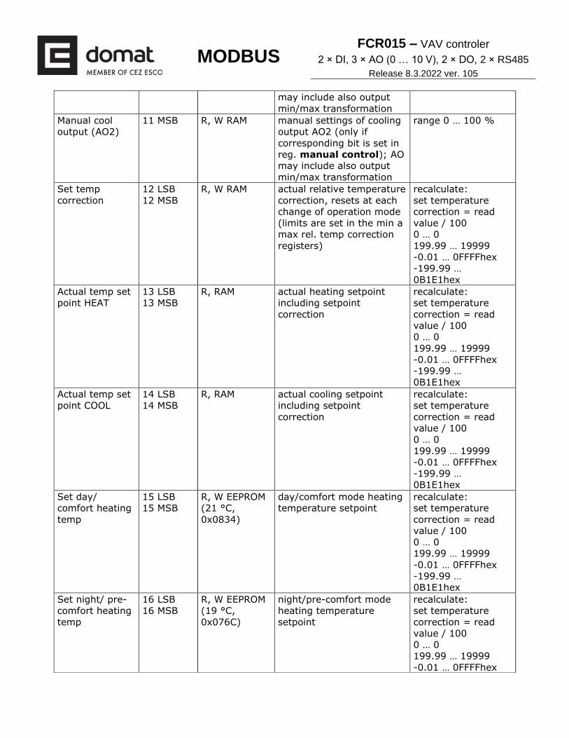
Set temp
correction
12 LSB
12 MSB
R, W RAM actual relative temperature
correction, resets at each
change of operation mode
(limits are set in the min a
max rel. temp correction
registers)
recalculate:
set temperature
correction = read
value / 100
0 … 0
199.99 … 19999
-0.01 … 0FFFFhex
-199.99 …
0B1E1hex
Actual temp set
point HEAT
13 LSB
13 MSB
R, RAM actual heating setpoint
including setpoint
correction
recalculate:
set temperature
correction = read
value / 100
0 … 0
199.99 … 19999
-0.01 … 0FFFFhex
-199.99 …
0B1E1hex
Actual temp set
point COOL
14 LSB
14 MSB
R, RAM actual cooling setpoint
including setpoint
correction
recalculate:
set temperature
correction = read
value / 100
0 … 0
199.99 … 19999
-0.01 … 0FFFFhex
-199.99 …
0B1E1hex
Set day/
comfort heating
temp
15 LSB
15 MSB
R, W EEPROM
(21 °C,
0x0834)
day/comfort mode heating
temperature setpoint
recalculate:
set temperature
correction = read
value / 100
0 … 0
199.99 … 19999
-0.01 … 0FFFFhex
-199.99 …
0B1E1hex
Set night/ pre-
comfort heating
temp
16 LSB
16 MSB
R, W EEPROM
(19 °C,
0x076C)
night/pre-comfort mode
heating temperature
setpoint
recalculate:
set temperature
correction = read
value / 100
0 … 0
199.99 … 19999
-0.01 … 0FFFFhex

MODBUS FCR015 – VAV controler
2 × DI, 3 × AO (0 … 10 V), 2 × DO, 2 × RS485
Release 8.3.2022 ver. 105
-199.99 …
0B1E1hex
Set depression/
economy
heating temp
17 LSB
17 MSB
R, W EEPROM
(12 °C,
0x04B0)
depression/economy mode
heating temperature
setpoint
recalculate:
set temperature
correction = read
value / 100
0 … 0
199.99 … 19999
-0.01 … 0FFFFhex
-199.99 …
0B1E1hex
Set day/
comfort cooling
temp
18 LSB
18 MSB
R, W EEPROM
(24 °C,
0x0960)
day/comfort mode cooling
temperature setpoints
recalculate:
set temperature
correction = read
value / 100
0 … 0
199.99 … 19999
-0.01 … 0FFFFhex
-199.99 …
0B1E1hex
Set night/ pre-
comfort cooling
temp
19 LSB
19 MSB
R, W EEPROM
(26 °C,
0x0A28)
night/pre-comfort mode
cooling temperature
setpoint
recalculate:
set temperature
correction = read
value / 100
0 … 0
199.99 … 19999
-0.01 … 0FFFFhex
-199.99 …
0B1E1hex
Set depression/
economy
cooling temp
20 LSB
20 MSB
R, W EEPROM
(35 °C,
0x0DAC)
depression/economy mode
heating temperature
setpoint
recalculate:
set temperature
correction = read
value / 100
0 … 0
199.99 … 19999
-0.01 … 0FFFFhex
-199.99 …
0B1E1hex
Actual temp 21 LSB
21 MSB
R, W RAM actual measured
temperature, incl.
temperature correction
(see temp sensor corr)
recalculate:
actual temperature
= (read value
+correction)/ 100
0 … 0
199.99 … 19999
-0.01 … 0FFFFhex
-199.99 …
0B1E1hex
Actual outside
temp
22 LSB
22 MSB
R, W RAM actual outside temperature recalculate:
actual temperature
= (read value
+correction)/ 100
MODBUS FCR015 – VAV controler
2 × DI, 3 × AO (0 … 10 V), 2 × DO, 2 × RS485
Release 8.3.2022 ver. 105
0 … 0
199.99 … 19999
-0.01 … 0FFFFhex
-199.99 …
0B1E1hex
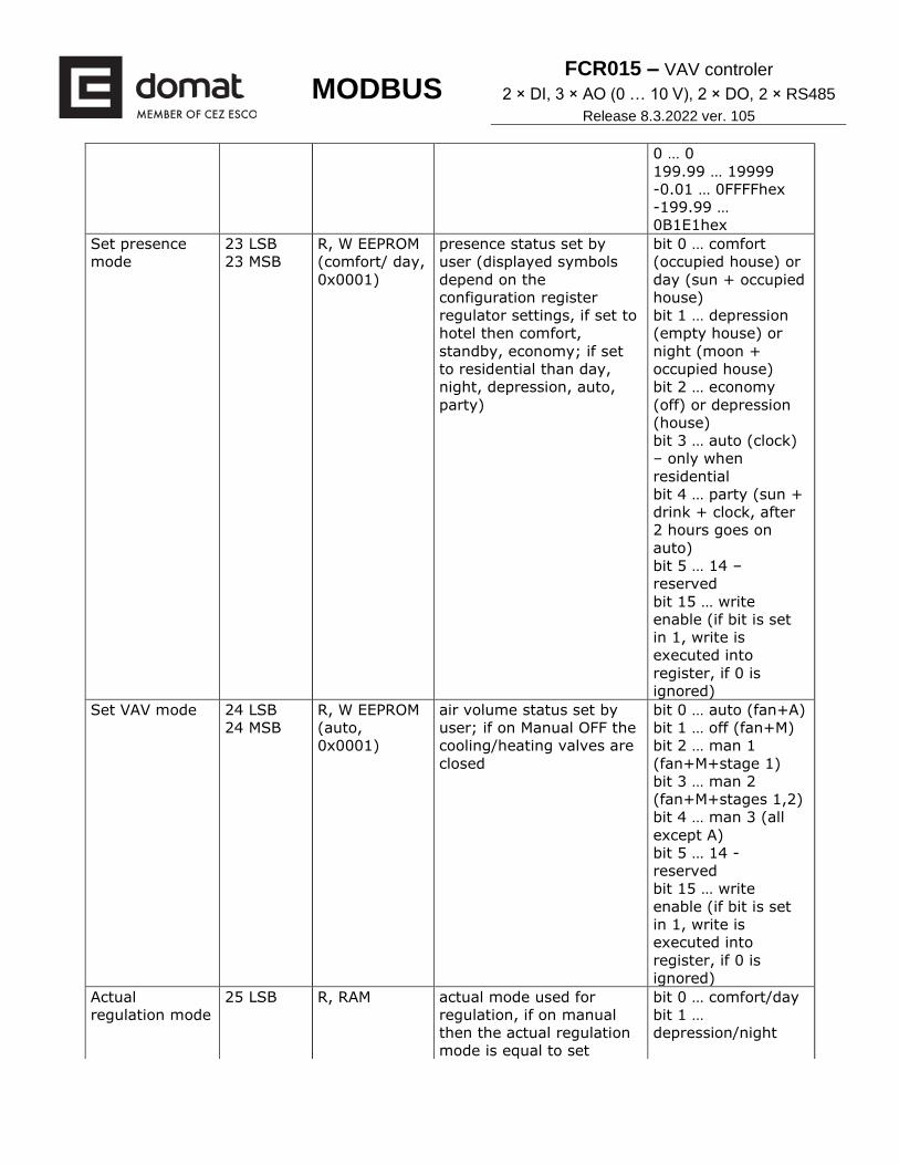
Set presence
mode
23 LSB
23 MSB
R, W EEPROM
(comfort/ day,
0x0001)
presence status set by
user (displayed symbols
depend on the
configuration register
regulator settings, if set to
hotel then comfort,
standby, economy; if set
to residential than day,
night, depression, auto,
party)
bit 0 … comfort
(occupied house) or
day (sun + occupied
house)
bit 1 … depression
(empty house) or
night (moon +
occupied house)
bit 2 … economy
(off) or depression
(house)
bit 3 … auto (clock)
– only when
residential
bit 4 … party (sun +
drink + clock, after
2 hours goes on
auto)
bit 5 … 14 –
reserved
bit 15 … write
enable (if bit is set
in 1, write is
executed into
register, if 0 is
ignored)
Set VAV mode 24 LSB
24 MSB
R, W EEPROM
(auto,
0x0001)
air volume status set by
user; if on Manual OFF the
cooling/heating valves are
closed
bit 0 … auto (fan+A)
bit 1 … off (fan+M)
bit 2 … man 1
(fan+M+stage 1)
bit 3 … man 2
(fan+M+stages 1,2)
bit 4 … man 3 (all
except A)
bit 5 … 14 -
reserved
bit 15 … write
enable (if bit is set
in 1, write is
executed into
register, if 0 is
ignored)
Actual
regulation mode
25 LSB R, RAM actual mode used for
regulation, if on manual
then the actual regulation
mode is equal to set
bit 0 … comfort/day
bit 1 …
depression/night
MODBUS FCR015 – VAV controler
2 × DI, 3 × AO (0 … 10 V), 2 × DO, 2 × RS485
Release 8.3.2022 ver. 105
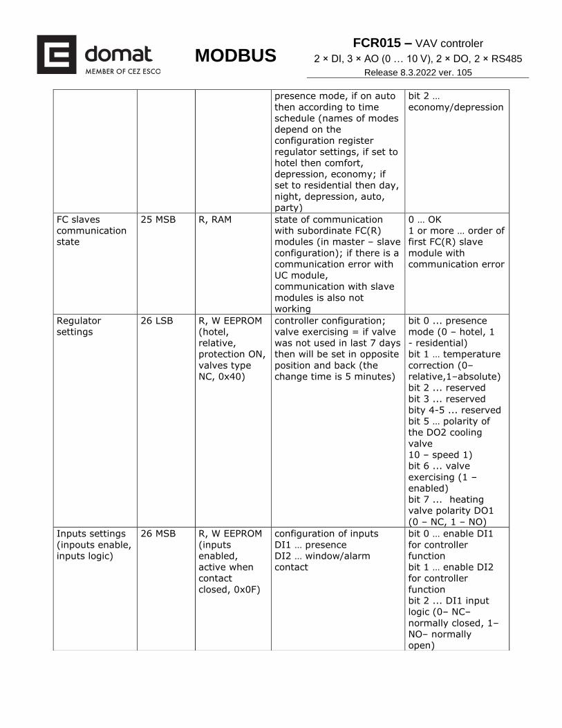
presence mode, if on auto
then according to time
schedule (names of modes
depend on the
configuration register
regulator settings, if set to
hotel then comfort,
depression, economy; if
set to residential then day,
night, depression, auto,
party)
bit 2 …
economy/depression
FC slaves
communication
state
25 MSB R, RAM state of communication
with subordinate FC(R)
modules (in master – slave
configuration); if there is a
communication error with
UC module,
communication with slave
modules is also not
working
0 … OK
1 or more … order of
first FC(R) slave
module with
communication error
Regulator
settings
26 LSB R, W EEPROM
(hotel,
relative,
protection ON,
valves type
NC, 0x40)
controller configuration;
valve exercising = if valve
was not used in last 7 days
then will be set in opposite
position and back (the
change time is 5 minutes)
bit 0 ... presence
mode (0 – hotel, 1
- residential)
bit 1 … temperature
correction (0–
relative,1–absolute)
bit 2 ... reserved
bit 3 ... reserved
bity 4-5 ... reserved
bit 5 … polarity of
the DO2 cooling
valve
10 – speed 1)
bit 6 ... valve
exercising (1 –
enabled)
bit 7 ... heating
valve polarity DO1
(0 – NC, 1 – NO)
Inputs settings
(inpouts enable,
inputs logic)
26 MSB R, W EEPROM
(inputs
enabled,
active when
contact
closed, 0x0F)
configuration of inputs
DI1 … presence
DI2 … window/alarm
contact
bit 0 … enable DI1
for controller
function
bit 1 … enable DI2
for controller
function
bit 2 ... DI1 input
logic (0– NC–
normally closed, 1–
NO– normally
open)

MODBUS FCR015 – VAV controler
2 × DI, 3 × AO (0 … 10 V), 2 × DO, 2 × RS485
Release 8.3.2022 ver. 105
bit 3 ... DI2 input
logic (0– NC –
normally closed, 1–
NO–normally
open)
P band / on-off
hysteresis
27 LSB
27 MSB
R, W EEPROM
(2 K, 0x0014)
Heating/cooling controller
P-band for PI control, or
hysteresis for ON-OFF
control
[in 0,1 K]
I const 28 LSB
28 MSB
R, W EEPROM
(15 min,
0x0384)
I constant of controller. If
out of bounds, a new
recalculated value is set
after restart
[in seconds]
if set to 0 =
disabled, P control
only
Regulator
settings 2
29 LSB R, W EEPROM
(fan speed
reset, slave
function
disabled, DI2
= window
contact,
correction
reset, PI
regulation,
autocalibration
enabled, 4-
pipe, 0xC9)
Controller configuration 2
Autocalibration – it is
presumed that during
measured period (7 days
with uninterupted power
supply) CO2 concentration
will drop to zero level
(outside concentration
400ppm). This will not
work with permanently
occupied rooms and it is
necesary to turn it off.
bit 0 ... fan speed
reset into AUTO
mode if presence
mode changes (TPG
change, user,
modbus)
bit 1 ... enable slave
mode (will not
actively
communicate with
UC010 – change
will be effective
after restart)
bit 2 ... DI2 as
alarm input (rather
than window
contact), switches
off all outputs when
active
bit 3 ... temperature
correction reset
when presence
mode changes
bit 4 ... control
mode (0 – PI, 1 –
On-Off)
bit 5 ... polarity of
the DO2 cooling
valve (0 – NC, 1 –
NO)
bit 6 ... internal CO2
auto-calibration
enable (loads only
after module power-
up)
bit 7 ... fancoil type

MODBUS FCR015 – VAV controler
2 × DI, 3 × AO (0 … 10 V), 2 × DO, 2 × RS485
Release 8.3.2022 ver. 105
(0...2-pipes, 1...4-
pipes)
Multi-slave
number
29 MSB R, W EEPROM
(multi-slave
off, 0x00)
number of slave FC(R)010
modules (connected on the
bus as UC010, from
modbus address 10), the
module with non-zero
multi-slave number serves
as master (The change
will become active only
after module restart)
0 … multi-slave
function OFF
1 or more … number
of slave FC(R)
modules
Actual primary
CO2 ppm
30 LSB
30 MSB
R, RAM actual value of CO2
sensor, in ppm with
correction (see register
40); readout period 16 s
[in ppm]
Latch enable 31 LSB R, W RAM Latch enable function for
individual inputs:
By writing 1 into the
register the particular bit
in the latched value
register is set to 0 and is
kept until the required
value is catched.
After reset the whole
register is set to 0
resetting of the
individual catched
bits in the latched
value register:
change the
particular bit from
log. 0 to log.1
(disable and enable
the latch function for
individual bits)
31 MSB reserved
Latched values 32 LSB R RAM latched values
0 – since latch enable
there was no change on
the bit
1 – since latch enable the
bit value has changed its
state
bit 0 is input 1
bit 1 is input 2;
to reset the bits,
disable and enable
latch, see latch
enable
32 MSB reserved
Min. rel. temp
correction
33 LSB
33 MSB
R, W EEPROM
(-5 °C,
0x01F4)
minimum relative
temperature correction set
by user, a positive value is
saved and taken as
negative one
recalculate: max
correction =
(read value/100);
10.00 … 1000
Max. rel. temp
correction
34 LSB
34 MSB
R, W EEPROM
(-5 °C,
0x01F4)
maximum relative
temperature correction set
by user
recalculate: max
correction =
(read value/100);
10.00 … 1000
Min day, night,
depression
temp
35 LSB
35 MSB
R, W EEPROM
(10 °C,
0x03E8)
minimum temperature
which user can set as
setpoint for day, night
and off modes
199.99 to 199.99
recalculate: min.
temperature= read
value / 100
0 … 0
199.99 … 19999
-0.01 … 0FFFFhex
MODBUS FCR015 – VAV controler
2 × DI, 3 × AO (0 … 10 V), 2 × DO, 2 × RS485
Release 8.3.2022 ver. 105
-199.99 …
0B1E1hex
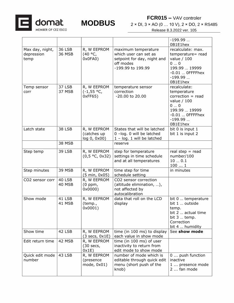
Max day, night,
depression
temp
36 LSB
36 MSB
R, W EEPROM
(40 °C,
0x0FA0)
maximum temperature
which user can set as
setpoint for day, night and
off modes
-199.99 to 199.99
recalculate: max.
temperature= read
value / 100
0 … 0
199.99 … 19999
-0.01 … 0FFFFhex
-199.99 …
0B1E1hex
Temp sensor
corr
37 LSB
37 MSB
R, W EEPROM
(-1,55 °C,
0xFF65)
temperature sensor
correction
-20.00 to 20.00
recalculate:
temperature
correction = read
value / 100
0 … 0
199.99 … 19999
-0.01 … 0FFFFhex
-199.99 …
0B1E1hex
Latch state 38 LSB R, W EEPROM
(catches up
log 0, 0x00)
States that will be latched
0 –log. 0 will be latched
1 – log. 1 will be latched
bit 0 is input 1
bit 1 is input 2
38 MSB reserve
Step temp 39 LSB R, W EEPROM
(0,5 °C, 0x32)
step for temperature
settings in time schedule
and at all temperatures
real step = read
number/100
10 … 0.1
100 ... 1 Step minutes 39 MSB R, W EEPROM
(5 min, 0x05)
time step for time
schedule setting
in minutes
CO2 sensor corr 40 LSB
40 MSB
R, W EEPROM
(0 ppm,
0x0000)
CO2 sensor correction
(altitude elimination, …),
not affected by
autocalibration
Show mode 41 LSB
41 MSB
R, W EEPROM
(temp.,
0x0001)
data that roll on the LCD
display
bit 0 … temperature
bit 1 … outside
temp.
bit 2 … actual time
bit 3 … temp.
Correction
bit 4 … humidity
Show time 42 LSB R, W EEPROM
(3 secs, 0x1E)
time (in 100 ms) to display
each value in show mode
See show mode
Edit return time 42 MSB R, W EEPROM
(30 secs,
0x1E)
time (in 100 ms) of user
inactivity to return from
edit mode to show mode
Quick edit mode
number
43 LSB R, W EEPROM
(presence
mode, 0x01)
number of mode which is
editable through quick edit
menu (short push of the
knob)
0 ... push function
inactive
1 ... presence mode
2 ... fan mode

MODBUS FCR015 – VAV controler
2 × DI, 3 × AO (0 … 10 V), 2 × DO, 2 × RS485
Release 8.3.2022 ver. 105
Changeover
delay switch
43 MSB R, W EEPROM
(30 mins,
0x3C)
time delay between switch
of heating/cooling
(protection of heat
exchanger)
Range [1-255 min]
Long push time 44 LSB R, W EEPROM
(1,5 secs,
0x0F)
time (in 100 ms)
evaluated as long push
for editing of the
presence or fan
mode
range [0,1 – 25,5 s]
Super long push
time
44 MSB R, W EEPROM
(5 secs, 0x32)
time (in 100 ms)
evaluated as superlong
push (go to settings menu
edit of RTC and
temperature
range [0,1 – 25,5 s]
Allowed
operation
modes
45 LSB
45 MSB
R, W EEPROM
(temp. corr.,
presence
mode, 0x101)
settings that is user
allowed to set
0 … disabled
1 … enabled
bit 0 … temp
corr.
bit 1 … day temp
bit 2 … night
temp bit 3 … depression temp
bit 4 … cooling day temp bit 5 … cooling night
temp
bit 6 … cooling
depression temp
bit 7 … RTC time
bit 8 … presence
mode
bit 9 … fan mode bit
10 … time
programme
Presence mode
edit mask
46 LSB
46 MSB
R, W EEPROM
(day / night,
0x0003)
states of presence mode
that user is able to switch
between
bit 0 … day (sun +
occupied house)
bit 1 … night (moon
+ occupied house)
bit 2 … depression
(empty house)
bit 3 … auto (clock)
bit 4 … party (sun +
drink + clock, after
2h goes to auto)
Fan mode edit
mask
47 LSB
47 MSB
R, W EEPROM
(all is editable,
0x001F)
states of fan mode that
user is able to set
bit 0 … auto (fan +
A)
bit 1 … off (fan +M)
bit 2 … man 1 (fan
+ M + stage 1)
bit 3 … man 2 (fan
+ M + stage 1 and
2)
bit 4 ... man 3 (all
except A)
MODBUS FCR015 – VAV controler
2 × DI, 3 × AO (0 … 10 V), 2 × DO, 2 × RS485
Release 8.3.2022 ver. 105
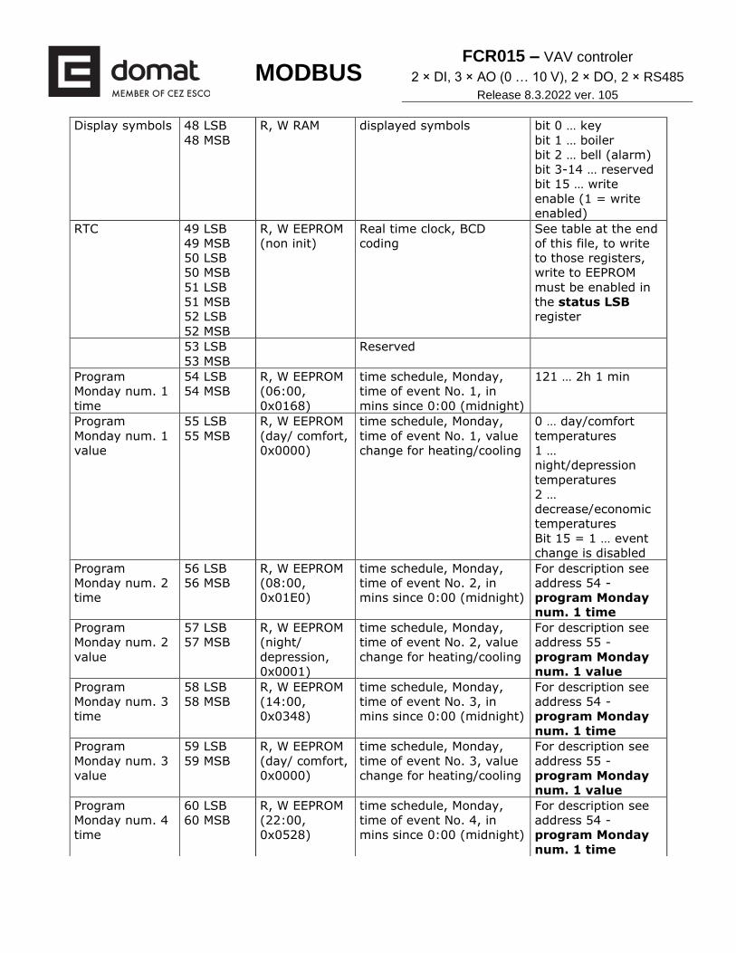
Display symbols 48 LSB
48 MSB
R, W RAM displayed symbols bit 0 … key
bit 1 … boiler
bit 2 … bell (alarm)
bit 3-14 … reserved
bit 15 … write
enable (1 = write
enabled)
RTC 49 LSB
49 MSB
50 LSB
50 MSB
51 LSB
51 MSB
52 LSB
52 MSB
R, W EEPROM
(non init)
Real time clock, BCD
coding
See table at the end
of this file, to write
to those registers,
write to EEPROM
must be enabled in
the status LSB
register
53 LSB
53 MSB
Reserved
Program
Monday num. 1
time
54 LSB
54 MSB
R, W EEPROM
(06:00,
0x0168)
time schedule, Monday,
time of event No. 1, in
mins since 0:00 (midnight)
121 … 2h 1 min
Program
Monday num. 1
value
55 LSB
55 MSB
R, W EEPROM
(day/ comfort,
0x0000)
time schedule, Monday,
time of event No. 1, value
change for heating/cooling
0 … day/comfort
temperatures
1 …
night/depression
temperatures
2 …
decrease/economic
temperatures
Bit 15 = 1 … event
change is disabled
Program
Monday num. 2
time
56 LSB
56 MSB
R, W EEPROM
(08:00,
0x01E0)
time schedule, Monday,
time of event No. 2, in
mins since 0:00 (midnight)
For description see
address 54 -
program Monday
num. 1 time
Program
Monday num. 2
value
57 LSB
57 MSB
R, W EEPROM
(night/
depression,
0x0001)
time schedule, Monday,
time of event No. 2, value
change for heating/cooling
For description see
address 55 -
program Monday
num. 1 value
Program
Monday num. 3
time
58 LSB
58 MSB
R, W EEPROM
(14:00,
0x0348)
time schedule, Monday,
time of event No. 3, in
mins since 0:00 (midnight)
For description see
address 54 -
program Monday
num. 1 time
Program
Monday num. 3
value
59 LSB
59 MSB
R, W EEPROM
(day/ comfort,
0x0000)
time schedule, Monday,
time of event No. 3, value
change for heating/cooling
For description see
address 55 -
program Monday
num. 1 value
Program
Monday num. 4
time
60 LSB
60 MSB
R, W EEPROM
(22:00,
0x0528)
time schedule, Monday,
time of event No. 4, in
mins since 0:00 (midnight)
For description see
address 54 -
program Monday
num. 1 time
MODBUS FCR015 – VAV controler
2 × DI, 3 × AO (0 … 10 V), 2 × DO, 2 × RS485
Release 8.3.2022 ver. 105
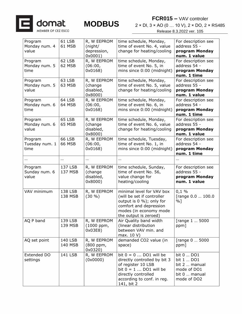
Program
Monday num. 4
value
61 LSB
61 MSB
R, W EEPROM
(night/
depression,
0x0001)
time schedule, Monday,
time of event No. 4, value
change for heating/cooling
For description see
address 55 -
program Monday
num. 1 value
Program
Monday num. 5
time
62 LSB
62 MSB
R, W EEPROM
(06:00,
0x0168)
time schedule, Monday,
time of event No. 5, in
mins since 0:00 (midnight)
For description see
address 54 -
program Monday
num. 1 time
Program
Monday num. 5
value
63 LSB
63 MSB
R, W EEPROM
(change
disabled,
0x8000)
time schedule, Monday,
time of event No. 5, value
change for heating/cooling
For description see
address 55 -
program Monday
num. 1 value
Program
Monday num. 6
time
64 LSB
64 MSB
R, W EEPROM
(06:00,
0x0168)
time schedule, Monday,
time of event No. 6, in
mins since 0:00 (midnight)
For description see
address 54 -
program Monday
num. 1 time
Program
Monday num. 6
value
65 LSB
65 MSB
R, W EEPROM
(change
disabled,
0x8000)
time schedule, Monday,
time of event No. 6, value
change for heating/cooling
For description see
address 55 -
program Monday
num. 1 value
Program
Tuesday num. 1
time
66 LSB
66 MSB
R, W EEPROM
(06:00,
0x0168)
time schedule, Tuesday,
time of event No. 1, in
mins since 0:00 (midnight)
For description see
address 54 -
program Monday
num. 1 time
… … … … …
Program
Sunday num. 6
value
137 LSB
137 MSB
R, W EEPROM
(change
disabled,
0x8000)
time schedule, Sunday,
time of event No. 56,
value change for
heating/cooling
For description see
address 55 -
program Monday
num. 1 value
VAV minimum 138 LSB
138 MSB
R, W EEPROM
(30 %)
minimal level for VAV box
(will be set if controller
output is 0 %); only for
comfort and depression
modes (in economy mode
the output is zeroed)
0,1 %
[range 0.0 … 100.0
%]
AQ P band 139 LSB
139 MSB
R, W EEPROM
(1000 ppm,
0x03E8)
Air Quality band width
(linear distribution
between VAV min. and
max. 10 V)
[range 1 … 5000
ppm]
AQ set point 140 LSB
140 MSB
R, W EEPROM
(800 ppm,
0x0320)
demanded CO2 value (in
space)
[range 0 … 5000
ppm]
Extended DO
settings
141 LSB R, W EEPROM
(0x0000)
bit 0 = 0 ... DO1 will be
directly controlled by bit 3
of register 10 LSB
bit 0 = 1 ... DO1 will be
directly controlled
according to conf. in reg.
141, bit 2
bit 0 … DO1
bit 1 … DO1
bit 2 … manual
mode of DO1
bit 0 … manual
mode of DO2

MODBUS FCR015 – VAV controler
2 × DI, 3 × AO (0 … 10 V), 2 × DO, 2 × RS485
Release 8.3.2022 ver. 105
bit 1 = 0 ... will be directly
controlled by bit 4 register
10 LSB
bit 1 = 1 ... DO2 will be
controlled according to
conf. in reg. 141 bit 3
bit 2 = 0 ... DO1 mirrors
AO1 at output (always as
PWM sequence)
bit 3 = 0 ... DO2 mirrors
AO2 at output (always as
PWM sequence)
bit 2 = 1 ... DO1 has PWM
sequence at output,
according to value of
register 142 LSB
bit 3 = 1 ... DO2 PWM
sequence at output,
according to value of
register 142 MSB (if set as
slave then this register is
set from master module)
141 MSB reserved
Manual heat
digital output
142 LSB R, W RAM manual control of output
DO1 (only if enabled in
reg. 141)
in %, range 0 … 100
%
Manual cool
digital output
142 MSB R, W RAM manual control of output
DO2 (only if enabled in
reg. 141)
in %, range 0 … 100
%
DO1 output 143 LSB
R, RAM state of output DO1 in % PWM (20 s
period) range 0 ...
100 %
DO2 output 143 MSB R, RAM state of output DO2 in % PWM (20 s
period) range 0 ...
100 %
144 LSB
144 MSB
R, RAM reserved
Actual rh 145 LSB
145 MSB
R, RAM Actual measured relative
humidity with incl. sensor
correction (see rh sensor
corr)
signed 16bit register
[0,01 %]
146 LSB
146 MSB
R, RAM reserved
rh sensor corr 147 LSB
147 MSB
R, W EEPROM
(+3,80 %)
Relative humidity sensor
correction
Signed 16bit
register
[0,01 %]
Backlight config 148 LSB
148 MSB
R, W EEPROM
(0x0009)
configuration of LCD and
knob backlight function.
bit 0 ... central enable of backlight functions (0 – off)

MODBUS FCR015 – VAV controler
2 × DI, 3 × AO (0 … 10 V), 2 × DO, 2 × RS485
Release 8.3.2022 ver. 105
If the bit 0 is centrally
disabled by 0, all backlight
functions are turned off.
If the bit 3 is enabled
(afterglow function) the
first user action
(press/turn button) switch
on backlight and the
second user action
(press/turn button) is
according defined user
function.
bit 1 … manual LCD
backlight (1 –
permanently switch
on backlight on level
LCD backlight
intensity high, this
function has higher
priority than
afterglow function,
0 – switch on backlight on level LCD backlight intensity low, afterglow function could change this level)
bit 2 … manual knob
backlight
(1 – permanently
switch on backlight
on level knob
backlight intensity
high, this function
has higher priority
than afterglow
function,
0 – switch on
backlight on level
knob backlight
intensity low,
afterglow function
could change this
level)
bit 3 … enable
afterglow
(1 – first user
activity, press or
turn button, set
backlight to high
intensity (see
registers LCD and
knob backlight int.
h.), after defined
time from the last
user activity (LCD
and knob b.
afterglow) set
backlight back to
low level;
0 – no response on
user activity)

MODBUS FCR015 – VAV controler
2 × DI, 3 × AO (0 … 10 V), 2 × DO, 2 × RS485
Release 8.3.2022 ver. 105
LCD backlight
intensity high
149 LSB R, W EEPROM
(100 %)
LCD backlight intensity –
higher intensity
[0 ... 100 %]
LCD backlight
intensity low
149 MSB R, W EEPROM
(0 %)
LCD backlight intensity –
lower intensity
[0 ... 100 %]
knob backlight
intensity high
150 LSB R, W EEPROM
(100 %)
knob backlight intensity –
higher intensity
[0 ... 100 %]
knob backlight
intensity low
150 MSB R, W EEPROM
(0 %)
knob backlight intensity –
lower intensity
[0 ... 100 %]
LCD backlight
afterglow
151 LSB R, W EEPROM
(3 secs)
time of LCD backlight after
last user activity
(turn/push knob) or after
end of edit (return to
scrolling mode), if value is
0 then no response on
user activity, if non-zero
value then it must be
bigger than register long
push time
[1 sec]
Knob backlight
afterglow
151 MSB R, W EEPROM
(3 secs)
time of knob backlight
after last user activity
(turn/push knob) or after
end of edit (return to
scrolling mode), if value is
0 then no response on
user activity, if non-zero
value then must be bigger
than register long push
time
[1 sec]
UC FW version 152 LSB
152 MSB
R, RAM FW version read from UC
module
AO1
configuration
154 LSB R, W EEPROM
(heating
sequence,
0x01)
Configuration of A01
output, in case of multiple
bits setting, the larger
output is selected; if bit 4
is set to 1 (CO2
sequence), then VAVmin
offset (reg. 138) is added
to the output; if bit 4 is set
to 1 (CO2 sequence) and
at the same time presence
mode is in third regulation
mode (depression), then
corresponding output is
set to zero (0V). If bit 4 is
set to 1 then bit 7 is
internally turned on.
bit 0 ... heating
sequence output +
C/O (0...100%)
bit 1 ... cooling
sequence output +
C/O (0...100%)
bit 2 ... heating
demand + C/O > 5
% => „DID Volume
Setpoint“, otherwise
0 %
bit 3 ... cooling
demand > 5 % =>
„DID Volume
Setpoint“, otherwise
0 %
bit 4 ... CO2
sequence output,
0...100%, subject of
manual control even
if not set in bit 7

MODBUS FCR015 – VAV controler
2 × DI, 3 × AO (0 … 10 V), 2 × DO, 2 × RS485
Release 8.3.2022 ver. 105
bit 5, 6 ... reserved
bit 7 ... output
manual control from
knob 0-1-2-3 (30-
70-100, automatic
mode not counted),
only for fan_mode
AO2
configuration
154 MSB R, W EEPROM
(cooling
sequence,
0x02)
configuration of A02
output
See reg. 154 LSB
AO3
configuration
155 LSB R, W EEPROM
(CO2 + knob,
0x90)
configuration of A03
output
See reg. 154 LSB
DID Volume
Setpoint
155 MSB R, W EEPROM
(100 %)
DID unit setting (Active
Chilled Beam)
[0 ... 100 %]
AO1 output 156 LSB R, RAM state of A01 output [0 ... 100 %]
AO3 output 156 MSB R, RAM state of A02 output [0 ... 100 %]
AO3 output 157 LSB R, RAM state of A03 output [0 ... 100 %]
157 MSB R, RAM reserved
AO1 min 158 LSB R, W EEPROM
(0 V)
minimal output AO1 value,
output transformation is
last sequence
in 0.1 V
[0.0 … 10.0 V]
AO1 max 158 MSB R, W EEPROM
(10 V, 100)
maximal output AO1
value, output
transformation is last
sequence
in 0.1 V
[0.0 … 10.0 V]
AO2 min 159 LSB R, W EEPROM
(0 V)
minimal output AO2 value,
output transformation is
last sequence
in 0.1 V
[0.0 … 10.0 V]
AO2 max 159 MSB R, W EEPROM
(10 V, 100)
maximal output AO2
value, output
transformation is last
sequence
in 0.1 V
[0.0 … 10.0 V]
AO3 min 160 LSB R, W EEPROM
(0 V)
minimal output AO3 value,
output transformation is
last sequence
in 0.1 V
[0.0 … 10.0 V]
AO3 max 160 MSB R, W EEPROM
(10 V, 100)
maximal output AO3
value, output
transformation is last
sequence
in 0.1 V
[0.0 … 10.0 V]
161 LSB
161 MSB
reserved – internal use
uptime 1000 LSB
1000 MSB
1001 LSB
1001 MSB
R uptime [secs]

MODBUS FCR015 – VAV controler
2 × DI, 3 × AO (0 … 10 V), 2 × DO, 2 × RS485
Release 8.3.2022 ver. 105
Address bit7 bit6 bit5 bit4 bit3 bit2 bit1 bit0 Function Range
49 LSB 10xSeconds Seconds Seconds 00-59
MSB 0 10xMinutes Minutes Minutes 00-59
LSB 0 10xHour
10xHour Hours Hours 00-23
MSB 0 0 0 0 0 Day Day 01-07
LSB 0 0 10xDate Date Date 01-31
MSB 0 0 10xMonth Month Month 01-12
LSB 10xYear Year Year 01-99
52 MSB 0 0 0 0 0 0 0 0 not used 00
Revision:
24. 06. 2019 ver. 103
20. 05. 2020 ver. 103_2 01. 05. 2021 ver. 104
14. 01. 2022 ver. 104 – stylistic adjustments, change logo
08. 01. 2022 ver. 104 – add 26 LSB bit 7, 29 LSB bit 5
SW reset 1002 LSB
1002 MSB
R, W RAM writing of non-zero value
executes module restart
(function must be enabled
in Status LSB bit 1).