MODBUS-RTU-AND-TCP-FOR-MODULYS ...
28
INSTALLATION AND OPERATING MANUAL www.socomec.com MODBUS RTU / MODBUS TCP For MODULYS XL UPS range EN
-
Upload
khangminh22 -
Category
Documents
-
view
4 -
download
0
Transcript of MODBUS-RTU-AND-TCP-FOR-MODULYS ...

INSTALLATION
AND
OPERATING
MANUAL
www.socomec.com
MODBUS RTU / MODBUS TCP
For MODULYS XL UPS range
EN


3ENEN_MODULYS XL Modbus RTU and TCP Manual_20_B
CONTENTS1. FOREWORD . . . . . . . . . . . . . . . . . . . . . . . . . . . . . . . . . . . . . . . . . . . . . . . . . . . . . . . . . . . . . . . . . . . 5
2. GENERAL AIM . . . . . . . . . . . . . . . . . . . . . . . . . . . . . . . . . . . . . . . . . . . . . . . . . . . . . . . . . . . . . . . . . . 5
3. MODBUS RTU – RS485 INTERFACE (ADC+SL CARD). . . . . . . . . . . . . . . . . . . . . . . . . . . . . . . . . . 6
3.1 InstallatIon of the RtU caRd . . . . . . . . . . . . . . . . . . . . . . . . . . . . . . . . . . . . . . . . . . . . . . . . . . . 6
4. MODBUS TCP – IDA INTERFACE (MODBUS TCP CARD) . . . . . . . . . . . . . . . . . . . . . . . . . . . . . . . 7
4.1 InstallatIon of the ModBUs tcP caRd . . . . . . . . . . . . . . . . . . . . . . . . . . . . . . . . . . . . . . . . . . . 7
4.2 seRIal connectIon defaUlt settIng . . . . . . . . . . . . . . . . . . . . . . . . . . . . . . . . . . . . . . . . . . . . . . . . 7
4.3 featURes and led descRIPtIon . . . . . . . . . . . . . . . . . . . . . . . . . . . . . . . . . . . . . . . . . . . . . . . . . . . 7
5. MODBUS UPS DATA ACCESS . . . . . . . . . . . . . . . . . . . . . . . . . . . . . . . . . . . . . . . . . . . . . . . . . . . . . 8
5.1 ModBUs gloBal taBle . . . . . . . . . . . . . . . . . . . . . . . . . . . . . . . . . . . . . . . . . . . . . . . . . . . . . . . 8
5.2 detaIl of data tyPe . . . . . . . . . . . . . . . . . . . . . . . . . . . . . . . . . . . . . . . . . . . . . . . . . . . . . . . . . . . 8
5.3 ModBUs addRess access level . . . . . . . . . . . . . . . . . . . . . . . . . . . . . . . . . . . . . . . . . . . . . . . . . 9
6. MODBUS TABLE FOR MODULYS XL . . . . . . . . . . . . . . . . . . . . . . . . . . . . . . . . . . . . . . . . . . . . . . 10
6.1 ModUlys Xl UnIt . . . . . . . . . . . . . . . . . . . . . . . . . . . . . . . . . . . . . . . . . . . . . . . . . . . . . . . . . 10
6.2 ModUlys Xl PaRallel systeM . . . . . . . . . . . . . . . . . . . . . . . . . . . . . . . . . . . . . . . . . . . . . . . . 11
6.3 UPs confIgURatIon ModBUs taBle . . . . . . . . . . . . . . . . . . . . . . . . . . . . . . . . . . . . . . . . . . . . . 12
6.4 UPS StatUS MODBUS taBle � � � � � � � � � � � � � � � � � � � � � � � � � � � � � � � � � � � � � � � � � � � � � � � � � � 13
6.5 UnIts oR ModUles synthesIs taBle . . . . . . . . . . . . . . . . . . . . . . . . . . . . . . . . . . . . . . . . . . . . . . 15
6.6 UPs alaRMs ModBUs taBle . . . . . . . . . . . . . . . . . . . . . . . . . . . . . . . . . . . . . . . . . . . . . . . . . . 16
6.7 UnIts oR ModUles synthesIs taBle . . . . . . . . . . . . . . . . . . . . . . . . . . . . . . . . . . . . . . . . . . . . . . 18
6.8 MeasUReMents taBle . . . . . . . . . . . . . . . . . . . . . . . . . . . . . . . . . . . . . . . . . . . . . . . . . . . . . . . . . 19
6.9 BatteRIes data access . . . . . . . . . . . . . . . . . . . . . . . . . . . . . . . . . . . . . . . . . . . . . . . . . . . . . . . . 21
6.10 UPs contRols ModBUs taBle . . . . . . . . . . . . . . . . . . . . . . . . . . . . . . . . . . . . . . . . . . . . . . . 22
6.11 UPs date and tIMe ModBUs taBle . . . . . . . . . . . . . . . . . . . . . . . . . . . . . . . . . . . . . . . . . . . . 23
6.12 eXteRnal BatteRy MonItoRIng RePoRt (lI-Ion BatteRy BMs connectIon) . . . . . . . . . . . . . . . . . . 23
7. MODBUS PROTOCOL . . . . . . . . . . . . . . . . . . . . . . . . . . . . . . . . . . . . . . . . . . . . . . . . . . . . . . . . . . 24
7.1 fUnctIons Used . . . . . . . . . . . . . . . . . . . . . . . . . . . . . . . . . . . . . . . . . . . . . . . . . . . . . . . . . . . . . 24
7.2 sUMMaRy of ModBUs fRaMe foRMat . . . . . . . . . . . . . . . . . . . . . . . . . . . . . . . . . . . . . . . . . . . . 24
8. MODBUS TCP IDA SPECIFICATION . . . . . . . . . . . . . . . . . . . . . . . . . . . . . . . . . . . . . . . . . . . . . . . 25
9. MODBUS TCP AGILIPLUG FINDER TOOL . . . . . . . . . . . . . . . . . . . . . . . . . . . . . . . . . . . . . . . . . . 25
10. APPENDIX 1: AGILIPUG INTERFACE . . . . . . . . . . . . . . . . . . . . . . . . . . . . . . . . . . . . . . . . . . . . . 26
11. APPENDIX 2: DIGI CONNECT ME INTERFACE. . . . . . . . . . . . . . . . . . . . . . . . . . . . . . . . . . . . . . 27

5ENEN_MODULYS XL Modbus RTU and TCP Manual_20_B
1. FOREWORD
Thank you for choosing a SOCOMEC product.
SOCOMEC reserves the right to modify their specifications at any time as far as this contributes to technical progress.
Conditions of use
Read these operating instructions carefully before using the MODBUS interface.
Repairs must only be carried out by suitably qualified, authorized staff.
It is advisable to keep the UPS environment below manufacturer-specified values for optimum operation.
UPS Operating Reference Standard
Comply with safety requirements.
Read the UPS operating instructions carefully.
2. GENERAL AIM
This document provides information on the MODBUS protocol serial link or Ethernet network for:
• MODULYS XL
Before connecting monitoring equipment or a BMS system (building management system) to the UPS, it is necessary to install and set up the serial interface or network configurations in the case of a network connection.
SOCOMEC retains the full and exclusive ownership rights over this document. Only a personal right to use the document for the application indicated by SOCOMEC is granted to the recipient of such document. The reproduc-tion, modification and distribution of this document, partially or in its entirety and in any way, is expressly prohibited except upon Socomec’s express prior written consent.
This document is not a specification. SOCOMEC reserves the right to make any changes to its content without prior notice.

6 EN EN_MODULYS XL Modbus RTU and TCP Manual_20_B
3. MODBUS RTU – RS485 INTERFACE (ADC+SL card)
3.1 Installation of the RTU cardThe interface must first be installed in the appropriate slot and fastened to the com slots using 2 screws.
USING ADC+SL OPTION
This board includes RS485 insulated serial link and advanced dry input and output contacts.
Installation
• Slot 1 or slot 2
• Screws for fixing
Cabling:
• RTX+ / RTX- connector
• Terminal resistor
MODBUS RTU serial setting via HMI:
• Slave number
• Baud rate (2400 / 9600 / 19200)
• Parity (none, even, odd)
• N bit (8)
• Stop bit set to 1 by default
NOTE!
Refers to ADC+SL quick start document.
IN1- IN1+IN2+
IN2-
IN1- IN1+IN3+
IN3-C2 NO2
NO4C4
C1 NO1C3 NO3
NC1

7ENEN_MODULYS XL Modbus RTU and TCP Manual_20_B
4. MODBUS TCP – IDA interface (MODBUS TCP card)
4.1 Installation of the MODBUS TCP cardThe interface must first be installed in the appropriate slot and fastened to the com slots using 2 screws.
4.2 Serial connection default settingSerial connection parameters are set by an auto baud rate procedure with a timeout of 40 seconds.
The Interface is operating when the LED TX is flashing every 10s, if no MODBUS TCP communication is engaged.
4.3 Features and LED descriptionStandard supported:
IEEE 802.3
Mode supported:
10/100Base-T
10/100Mbps (auto sensing)
Half-duplex & Full-duplex mode (auto sensing)
Connector type:
RJ-45
LED type Color Meaning
RJ45
Yellow Line detected
Yellow flashing Searching line
Off No Ethernet line
RJ45
Green ON
Green flashing MODBUS TCP Traffic
Off No traffic
Interface LED TX ON Green When transmitting data
Interface LED RX ON Green When receiving data
5V ISO

8 EN EN_MODULYS XL Modbus RTU and TCP Manual_20_B
5. MODBUS UPS DATA ACCESS
5.1 MODBUS global table
Address Table Data Type Description Length in word Acronym Access
0x0001 UPS Configuration integer bit field List of configurations 15 T001 – T015 Read
0x0010 Serial Number char String 10 R000 Read
0x001A Socomec ref char Socomec range name 10 R001 Read
0x0024 User device ref char Custom reference 6 R002 Read
0x002A User device location char Customer location 6 R003 Read
0x0030 Status bit Bits field8 for Unit
6 for ModuleS000-S127 Read
0x0038 Alarms bit Bits field8 for Unit
6 for ModuleA000-A127 Read
0x0040 Measurementssigned int
unsigned intList of values 80 M000-M079 Read
0x00C0Measurements Control
Managementbit
Bits field:
1 = measure available7 D000-D006 Read
0x00C7 Permissions bitBits field:
1 = this control is enabled2 P000-P031 Read
0x00C9 UPS Controls bitBits field:
1 bit = 1 control2 C000-C031 Write
0x00CB UPS clock integer Msb/lsb format 5 K000-K004 R / W
5.2 Detail of data type
Word - unsigned or signed integer format
b15 b14 b13 b12 b11 b10 b09 b08 b07 b06 b05 b04 b03 b02 b01 b00
16bits value
0 … 65535
-32768 … 32768
Word - ASCII format
b15 b14 b13 b12 b11 b10 b09 b08 b07 b06 b05 b04 b03 b02 b01 b00
MSB lsb
Char 1 Char 2
Word - 16 bits field
b15 b14 b13 b12 b11 b10 b09 b08 b07 b06 b05 b04 b03 b02 b01 b00
A015 Alarms bit A000
S015 Status bit S000

9ENEN_MODULYS XL Modbus RTU and TCP Manual_20_B
5.3 MODBUS address access level
The MODBUS address is composed of one MSB (Most Significant Byte) and one lsb (Lowest Significant Byte).
The MSB defines the level of device (System, Unit and subunit), and the lsb the UPS data.
MODBUS Address MSB + lsb
MSB = Device access level lsb = MODBUS table
0x00 = UPS System
0xu0 = Unit (u = unit number)
0xum = Module access (m = module number)
0x01 = Configurations
0x30 = Status
0x38 = Alarms
0x40 = measurements
0xC0 = measure control table
MODBUS tables accessible only at SYSTEM level
0x00 = UPS System
0xCB = UPS Date and time (read/write)
0xC7 = UPS control permission (read)
0xC9 = UPS system control (write)
Restrictions: the units and modules controls are not available from MODBUS interface.

10 EN EN_MODULYS XL Modbus RTU and TCP Manual_20_B
6. MODBUS TABLE FOR MODULYS XL
6.1 MODULYS XL Unit
Power Module Power Module Power Module Power Hub Power Module Power Module Power Module
1 2 3 Unit 4 5 6
1 2 3 4 5 6
XC6
XC7
XC5HP698
XC6
XC7
XC5HP698
XC6
XC7
XC5HP698
XC6
XC7
XC5HP698
XC6
XC7
XC5HP698
XC6
XC7
XC5HP698
Com-Slot location in Power HUB
The Power Module number is defined during commissioning. It could be that the numbering does not follow this example.
6.1.1 MODBUS address table for MODULYS XL UnitThe MODBUS interface allows reading data of the MODULYS XL Unit and of all Power MODULE connected.
The MODBUS access selection for Unit or Modules access is defined by the MSB of the MODBUS address.
Access levelMODBUS Address MSB
Defines the levelMODBUS Address lsb
Defined the MODBUS table
MODULYS XL Unit 0x00 or 0x10
for example:
0x30 = status
0x38 = alarms
0x40 = measurements
Power MODULE 1 0x11
Power MODULE 2 0x12
Power MODULE 3 0x13
Power MODULE 4 0x14
Power MODULE 5 0x15
Power MODULE 6 0x16
Example:
To read status of module 2: address = 0x1230
To read alarms of module 4: address = 0x1438

11ENEN_MODULYS XL Modbus RTU and TCP Manual_20_B
6.2 MODULYS XL Parallel System
In case of MODULYS XL parallel system the MODBUS interface is installed on unit 1 by default. This MODBUS inter-
face allows reading the data of all units and modules of the system.
6.2.1 MODBUS address table for MODULYS XL system
The MODBUS interface allows reading data of the MODULYS XL System, Units and of all Power Modules connected.
The MODBUS access selection for Units or Modules access is defined by the MSB of the MODBUS address.
Access levelMODBUS Address MSB
Defines the levelMODBUS Address lsb
Defined the MODBUS table
SYSTEM 0x00
for example:
0x30 = status
0x38 = alarms
0x40 = measurements
Unit 1 0x10
Unit 2 0x20
Unit 3 0x30
Unit 4 0x40
u = Unit number
Power MODULE 1 0xu1
Power MODULE 2 0xu2
Power MODULE 3 0xu3
Power MODULE 4 0xu4
Power MODULE 5 0xu5
Power MODULE 6 0xu6
Example:
To read status of Unit 1 - module 2: address = 0x1230
To read alarms of Unit 2 - module 4: address = 0x2438
NOTE: the data at System level is a combination of data coming from all units. This level has to be seen as 'Con-
centrator' of the all data of the UPS. The combination from Units level to System level is mostly done with an 'OR'
combination, except specific status or alarms linked to redundancy management.

12 EN EN_MODULYS XL Modbus RTU and TCP Manual_20_B
6.3 UPS configuration MODBUS table6.3.1 System configuration (0x0001 – 15 words)
ADD ACRON Description MSB: UPS installation Code LSB: Device type
0x0001 T001 UPS ID Code 6 Modular Parallel System 9 Modular UNIT
0x0002 T002 Number of units 1 to 4
0x0003 T003 Position of Unitsb15 b14 … b11 … b05 b04 b03 b02 b01 b00
Unit presence
0x0004 T004 Device number Unit number where the interface is connected
0x0005 T005 Nominal kVA *10 if 0x000E = 1
0x0006 T006 Nominal kW *10 if 0x000E = 1
0x0007 T007 Phases number Input phases 1 – 3 Output phases 1 - 3
0x0008 T008 Function
b00 = 1 if eco mode functioning is enabled
b01 = 1 if energy saver function is enabled
b02 = 1 if Line-Interactive mode enabled
0x0009 T009 Reserved
0x000A T010 UPS Backup
b00 = 1 if battery present
b03 = 1 for battery Li-ion
b15 = 1 if the battery is shared0x000B T011 Reserved
0x000C T012 UPS Backup ID cf unit configuration
0x000D T013 Reserved
0x000E T014 Measurements factor 0 = no factor / 1 = factor * 10
0x000F T015 Device reference code 0x81A0 MODULYS XL
6.3.2 Unit configuration (0xu001 – 15 words)
ADD ACRON Description MSB: UPS installation Code LSB: Device type
0xu001 T001 UPS ID Code 9 Modular Unit 1 UPS / Unit
0xu002 T002 Number of devices1 to 15
This number includes number of Modules + Bypass + additional devices
0xu003 T003 Position of devices presentb15 b14 … b11 … b05 b04 b03 b02 b01 b00
MP 6 PM 5 PM 4 PM 3 PM 2 PM 1bypass device Power Module presence
0xu004 T004 Device number Unit number
0xu005 T005 Nominal kVA *10 if 0x000E = 1
0xu006 T006 Nominal kW *10 if 0x000E = 1
0xu007 T007 Phases number Input phases 1 – 3 Output phases 1 - 3
0xu008 T008 Function cf system table
0xu009 T009 Reserved
0xu00A T010 UPS Backup
b00 = 1 if battery present
b03 = 1 for battery Li-ion
b15 = 1 if the battery is shared
0xu00B T011 Reserved
0xu00C T012 UPS Backup ID number of batteries
0xu00D T013 Reserved
0xu00E T014 Measurements factor 0 = no factor / 1 = factor * 10

13ENEN_MODULYS XL Modbus RTU and TCP Manual_20_B
6.4 UPS status MODBUS table: (MSB)(0x30) – 6 words
How to read the table:
The lsb has to be added to the MSB to build the MODBUS address according the level and the table to read.
MODBUS address = level + table = MSB + lsb
MODBUS TABLE MSB of MODBUS Address
Grouplsb of MODBUS Address
Bits Acronym Description
SystemUnit 1 to 4
Mod. 1 to 6
u = unit number
0x000x01
to0x04
0xu1to
0xu6
0x30
b00 S000 Load protected by Inverter X X X
OUTPUT
STATUS
b01 S001 b02 S002 Load supplied by automatic Bypass X X b03 S003 Load supplied by Maintenance Bypass X X b04 S004 Load OFF X X Xb05 S005 b06 S006 In eco mode (**) X X
FUNCTIONING
MODE
b07 S007 energy saver (**) X X b08 S008 b09 S009 In Service mode X X Xb10 S010 Line-Interactive mode (**) X X b11 S011 Operating X X X
DEVICE STATUSb12 S012 Available X X Xb13 S013 On Standby X X Xb14 S014 Isolated X X b15 S015 Maintenance Alert X X
0x31
b00 S016 Output Breaker closed X X
DEVICE
ENVIRONMENT
b01 S017 Maintenance Bypass closed X X b02 S018 External Maintenance Bypass closed (*) b03 S019 External Output Breaker closed (*) b04 S020 b05 S021 Rectifier Input Breaker (*) b06 S022 Bypass Input Breaker (*) b07 S023 Gen set ON (*) b08 S024 b09 S025 b10 S026 Automatic Start in progress X X
PROCEDURES
b11 S027 Maint. Bypass procedure in progress X X b12 S028 b13 S029 b14 S030 Auto-test Procedure in progress X b15 S031 Alarm Ack. request X X

14 EN EN_MODULYS XL Modbus RTU and TCP Manual_20_B
lsb bits Acronym DescriptionsSystem0x00
Unit0xu0
Module0xum
Group
0x32
b00 S032 Battery OK X X
BATTERY
b01 S033 Battery charged X X b02 S034 Battery Test in progress X X b03 S035 Battery Test programmed X X b04 S036 Battery charging X X b05 S037 Battery Test interrupted X X b06 S038 b07 S039 Battery discharge to Input (**) X X b08 S040 UPS Backup connected (*)
DC STORAGEb09 S041 UPS Backup charged / ready (*) b10 S042 UPS Backup charging (*) b11 S043 b12 S044 b13 S045 b14 S046 b15 S047
0x33
b00 S048 Rectifier Input Supply present X X X
RECTIFIERb01 S049 Rectifier ON X X Xb02 S050 Charger ON X X Xb03 S051 b04 S052 Inverter ON X X X
INVERTERb05 S053 Inverter Switch ON X X Xb06 S054 b07 S055 Bypass output breaker closed X X b08 S056 Bypass Input Supply present X X
BYPASSb09 S057 Bypass Static Switch closed X X b10 S058 Bypass Input & Inverter synchronized X X b11 S059 ACS external synchronization (*) X X b12 S060 b13 S061 b14 S062 b15 S063
0x34
b00 S064 Card in Slot 1 present (*) X X
OPTIONS
b01 S065 Card in Slot 2 present (*) X X b02 S066 Card in Slot 1-Ext present (*) X X b03 S067 Card in Slot 2-Ext present (*) X X b04 S068 Card in Slot 3/SYST present X X b05 S069 b06 S070 Profile login 1(**) b07 S071 Profile login 2 (**) b08 S072 Programmable S072 (*) X X
ADC Card
IN/OUT
b09 S073 Programmable S073 (*) X X b10 S074 Programmable S074 (*) X X b11 S075 Programmable S075 (*) X X b12 S076 Programmable S076 (*) X X b13 S077 Programmable S077 (*) X X b14 S078 Programmable S078 (*) X X b15 S079 Programmable S079 (*) X X

15ENEN_MODULYS XL Modbus RTU and TCP Manual_20_B
0x35
b00 S080
MISC.
b01 S081 b02 S082 b03 S083 b04 S084 Backfeed protection open (*) X X b05 S085 b06 S086 b07 S087 b08 S088 b09 S089 b10 S090 b11 S091 b12 S092 b13 S093 b14 S094 b15 S095
(*) available if the option is present or linked to additional info coming from ADC+SL Option card.
(**) available if the function is enabled.
6.5 Units or Modules Synthesis Table: (MSB)(0x36) – 2 Wordslsb bits Acronym Descriptions System 0x00 Unit 0xu0 Group
0x36
b00 S096 1 Operating Unit 1 Module 1
UNITS or
MODULES
SYNTHESIS
b01 S097 2 Operating Unit 2 Module 2b02 S098 3 Operating Unit 3 Module 3b03 S099 4 Operating Unit 4 Module 4b04 S100 5 Operating Module 5b05 S101 6 Operating Module 6b06 S102b07 S103b08 S104b09 S105b10 S106 b11 S107 b12 S108 b13 S109 Bypass Operating Xb14 S110 b15 S111
0x37
b00 S112 1 Available Unit 1 Module 1
UNITS or
MODULES
SYNTHESIS
b01 S113 2 Available Unit 2 Module 2b02 S114 3 Available Unit 3 Module 3b03 S115 4 Available Unit 4 Module 4b04 S116 5 Available Module 5b05 S117 6 Available Module 6b06 S118b07 S119b08 S120b09 S121b10 S122 b11 S123 b12 S124 b13 S125 Bypass Available Xb14 S126 b15 S127

16 EN EN_MODULYS XL Modbus RTU and TCP Manual_20_B
6.6 UPS alarms MODBUS table: (MSB)(0x38) – 6 words
MODBUS TABLE MSB of MODBUS Address
Grouplsb
of MODBUSAddress
Bits Acronym Description
System Unit 1 to 4Mod. 1 to 6
u = unitnumber
0x000x01
to0x04
0xu1to
0xu6
0x38
b00 A000 Imminent Stop X X X
LOAD
b01 A001 Overload X X Xb02 A002 Ambient Temperature Alarm X X Xb03 A003 Transfer locked X X b04 A004 Transfer impossible X X b05 A005 Insufficient Resources X X b06 A006 Redundancy loss X X b07 A007 b08 A008 eco mode disabled by UPS X X
MODEb09 A009 energy saver disabled by UPS X X b10 A010 On bypass for 1 hour X X b11 A011 Wrong password entered(**) b12 A012 Maintenance Alarm X X
SERVICEb13 A013 Remote Service Alarm X X b14 A014 Remote Service Preventive Alarm X X b15 A015 General Alarm X X X
0x39
b00 A016 Battery disconnected X X
BATTERY
b01 A017 Battery discharged X X b02 A018 End of Backup Time - Battery Low X X b03 A019 Battery discharging X X b04 A020 Battery Temperature Alarm (*) X X b05 A021 Battery Room Alarm (*) X X b06 A022 Battery Test failed X X b07 A023 b08 A024 b09 A025 b10 A026 Insulation fault X X b11 A027 Battery Alarm X X b12 A028 battery preventive alarm (***) b13 A029 UPS Backup critical Alarm (*)
DC BACKUPb14 A030 UPS Backup preventive alarm (*) b15 A031 UPS Backup not OK (*)

17ENEN_MODULYS XL Modbus RTU and TCP Manual_20_B
lsb bits Acronym Descriptions System 0x00
Unit0xu0
Module0xum Group
0x3A
b00 A032 Rectifier Critical Alarm X X
RECTIFIER
b01 A033 Rectifier Preventive Alarm X Xb02 A034b03 A035 Rectifier Input Supply not OK X Xb04 A036b05 A037 Charger Critical Alarm X Xb06 A038 Charger Preventive Alarm X Xb07 A039 Battery discharge interrupted Xb08 A040 Inverter Critical Alarm X X
INVERTER
b09 A041 Inverter Preventive Alarm X Xb10 A042b11 A043 Imminent redundancy lost Xb12 A044 Consumable alarm Xb13 A045b14 A046b15 A047
0x3B
b00 A048 Bypass Critical Alarm X X
BYPASS
b01 A049 Bypass Preventive Alarm X X b02 A050 Bypass Input Supply not OK X X b03 A051 Phase Rotation fault X X b04 A052 Bypass Backfeed detection X X b05 A053 b06 A054 Fan Failure X X b07 A055 ACS Alarm (**) X X b08 A056 Maintenance Bypass Alarm X X b09 A057 Internal Backfeed detection X X b10 A058 Battery Monitoring Alarm(**)
OPTION
b11 A059 UPS Power OFF X X b12 A060 Wrong Configuration X X b13 A061 Internal / Communication failure X X b14 A062 Option Board Alarm (*) X X b15 A063 Spare part not compatible X X
0x3C
b00 A064 Programmable A064 (*) X X
ADC Card
IN/OUT
b01 A065 Programmable A065(*) X X b02 A066 Programmable A066 (*) X X b03 A067 Programmable A067 (*) X X b04 A068 Programmable A068 (*) X X b05 A069 Programmable A069 (*) X X b06 A070 Programmable A070 (*) X X b07 A071 Programmable A071 (*) X X b08 A072 Line-Interactive mode disabled by UPS X b09 A073 b10 A074 b11 A075 b12 A076 b13 A077 b14 A078 b15 A079
(*) available if the option is present or linked to additional info coming from ADC+SL Option card.
(**) available if the function is enabled.
(***) info updated from Battery management system in case of Li-ion batteries for example

18 EN EN_MODULYS XL Modbus RTU and TCP Manual_20_B
lsb bits Acronym Descriptions 0x000x01
to0x04
0xu1to
0xu6Group
0x3D
b00 A080 Customer Installation Overload
MISC.
b01 A081 b02 A082 b03 A083 b04 A084 b05 A085 b06 A086 b07 A087 b08 A088 b09 A089 b10 A090 b11 A091 b12 A092 b13 A093 b14 A094 b15 A095
6.7 Units or Modules Synthesis Table (MSB) (0x3E – 2 words)
lsb Bits Acronym Descriptions 0x000x01
to0x04
0xu1to
0xu6Group
0x3E
b00 A096 1 General Alarm Unit 1 Module 1
Units or
Modules
SYNTHESIS
b01 A097 2 General Alarm Unit 2 Module 2b02 A098 3 General Alarm Unit 3 Module 3b03 A099 4 General Alarm Unit 4 Module 4b04 A100 5 General Alarm Module 5b05 A101 6 General Alarm Module 6b06 A102 b07 A103 b08 A104 b09 A105 b10 A106 b11 A107 b12 A108 b13 A109 Bypass General Alarm b14 A110 b15 A111
0x3F
b00 A112 1 Imminent STOP Unit 1 Module 1
Units or
Modules
SYNTHESIS
b01 A113 2 Imminent STOP Unit 2 Module 2b02 A114 3 Imminent STOP Unit 3 Module 3b03 A115 4 Imminent STOP Unit 4 Module 4b04 A116 5 Imminent STOP Module 5b05 A117 6 Imminent STOP Module 6b06 A118b07 A119b08 A120b09 A121b10 A122 b11 A123 b12 A124 b13 A125 Bypass Imminent STOPb14 A126 b15 A127

19ENEN_MODULYS XL Modbus RTU and TCP Manual_20_B
6.8 Measurements table (MSB) (0x40 – 80 words)
The MSB of the MODBUS address is managed in the same manner as for other tables. For System the MSB=0x00,
for Unit the MSB=0xu0 (u=Unit number) and for Module the MSB=0xum (m=module number)
ACRON. lsb MEASUREMENTSFORMAT0x000E=0
FORMAT0x000E=1
MCMT1 SystemUnit
Module
M000 0x40 Output load rate % ### ### 0xC0b00 X X
M001 0x41 Output load rate L1 % ### ### 0xC0b01 X X
M002 0x42 Output load rate L2 % ### ### 0xC0b02 X X
M003 0x43 Output load rate L3 % ### ### 0xC0b03 X X
M004 0x44 Output kVA ## ### # ###.# 0xC0b04 X X
M005 0x45 Output kW ## ### # ###.# 0xC0b05 X X
M006 0x46 Output current L1 A ## ### # ###.# 0xC0b06 X X
M007 0x47 Output current L2 A ## ### # ###.# 0xC0b07 X X
M008 0x48 Output current L3 A ## ### # ###.# 0xC0b08 X X
M009 0x49
M010 0x4A Output voltage L1 V ### ### 0xC0b10 X X
M011 0x4B Output voltage L2 V ### ### 0xC0b11 X X
M012 0x4C Output voltage L3 V ### ### 0xC0b12 X X
M013 0x4D Output frequency x10Hz ##.# ##.# 0xC0b13 X X
M014 0x4E Output crest factor
M015 0x4F Ambient T° °C ##.# ##.# 0xC0b15 X X
M016 0x50 Battery voltage V (*) # ### ###.# 0xC1b00 X
M017 0x51
M018 0x52 Battery current A (*) ## ### # ###.# 0xC1b02 X
M019 0x53
M020 0x54
M021 0x55 (Min States Of Health % *) ### ### 0xC1b05
M022 0x56Battery capacity % (States Of Charge % *)
### ### 0xC1b06 X
M023 0x57 Battery capacity Ah (*) ## ### # ###.# 0xC1b07 X
M024 0x58 Bat. remaining backup time mn (*) ### ### 0xC1b08 X
M025 0x59 Time on battery s (*) ### ### 0xC1b09 X
M026 0x5A Battery temperature (*) ##.# ##.# 0xC1b10 X
M027 0x5B Battery temperature average ##.# ##.# 0xC1b11 X
M028 0x5C
M029 0x5D
M030 0x5E
M031 0x5F
M032 0x60 Rect. input supply volt. L1 V ### ### 0xC2b00 X X
M033 0x61 Rect. input supply volt. L2 V ### ### 0xC2b01 X X
M034 0x62 Rect. input supply volt. L3 V ### ### 0xC2b02 X X
M035 0x63 Rect. input supply freq. x10Hz ##.# ##.# 0xC2b03 X X
M036 0x64 Rect. input supply volt. U12 V ### ### 0xC2b04 X X
M037 0x65 Rect. input supply volt. U23 V ### ### 0xC2b05 X X

20 EN EN_MODULYS XL Modbus RTU and TCP Manual_20_B
ACRON. lsb MEASUREMENTSFORMAT0x000E=0
FORMAT0x000E=1
MCMT1 SystemUnit
Module
M038 0x66 Rect. input supply volt. U31 V ### ### 0xC2b06 X X
M039 0x67 Bypass input supply voltage L1 ### ### 0xC2b07 X
M040 0x68 Bypass input supply voltage L2 ### ### 0xC2b08 X
M041 0x69 Bypass input supply voltage L3 ### ### 0xC2b09 X
M042 0x6A Bypass input supply freq x10Hz ##.# ##.# 0xC2b10 X
M043 0x6B Bypass input supply volt U12 V ### ### 0xC2b11 X
M044 0x6C Bypass input supply volt U23 V ### ### 0xC2b12 X
M045 0x6D Bypass input supply volt U31 V ### ### 0xC2b13 X
M046 0x6E
M047 0x6F
M048 0x70 Output Apparent P. L1 KVA ## ### # ###.# 0xC3b00 X X
M049 0x71 Output Apparent P. L2 KVA ## ### # ###.# 0xC3b01 X X
M050 0x72 Output Apparent P. L3 KVA ## ### # ###.# 0xC3b02 X X
M051 0x73 Output Active Power L1 KW ## ### # ###.# 0xC3b03 X X
M052 0x74 Output Active Power L2 KW ## ### # ###.# 0xC3b04 X X
M053 0x75 Output Active Power L3 KW ## ### # ###.# 0xC3b05 X X
M054 0x76 Output voltage U12 V ### ### 0xC3b06 X X
M055 0x77 Output voltage U23 V ### ### 0xC3b07 X X
M056 0x78 Output voltage U31 V ### ### 0xC3b08 X X
M057 0x79 Output Power factor L1 #.## #.## 0xC3b09 X
M058 0x7A Output Power factor L2 #.## #.## 0xC3b10 X
M059 0x7B Output Power factor L3 #.## #.## 0xC3b11 X
M060 0x7C
M061 0x7D
M062 0x7E
M063 0x7F
M064 0x80 Rect. Input Current L1 A ## ### # ###.# 0xC4b00 X X
M065 0x81 Rect. Input Current L2 A ## ### # ###.# 0xC4b01 X X
M066 0x82 Rect. Input Current L3 A ## ### # ###.# 0xC4b02 X X
M067 0x83 Rect. Active Power L1 KW +/-## ### +/-# ###.# 0xC4b03 X X
M068 0x84 Rect. Active Power L2 KW +/-## ### +/-# ###.# 0xC4b04 X X
M069 0x85 Rect. Active Power L3 KW +/-## ### +/-# ###.# 0xC4b05 X X
M070 0x86 Bypass Input Current L1 A ## ### # ###.# 0xC4b06 X
M071 0x87 Bypass Input Current L2 A ## ### # ###.# 0xC4b07 X
M072 0x88 Bypass Input Current L3 A ## ### # ###.# 0xC4b08 X
M073 0x89 Bypass Power L1 KW ## ### # ###.# 0xC4b09 X
M074 0x8A Bypass Power L2 KW ## ### # ###.# 0xC4b10 X
M075 0x8B Bypass Power L3 KW ## ### # ###.# 0xC4b11 X
M076-79 Reserved
(*) measurements updated from Battery management system in case of Li-ion batteries for example1 Measurements Control Management Table
21ENEN_MODULYS XL Modbus RTU and TCP Manual_20_B
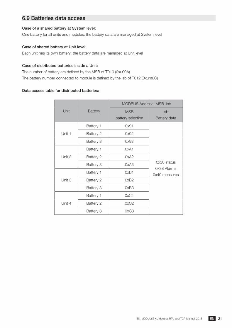
6.9 Batteries data access
Case of a shared battery at System level:
One battery for all units and modules: the battery data are managed at System level
Case of shared battery at Unit level:
Each unit has its own battery: the battery data are managed at Unit level
Case of distributed batteries inside a Unit:
The number of battery are defined by the MSB of T010 (0xu00A)
The battery number connected to module is defined by the lsb of T012 (0xum0C)
Data access table for distributed batteries:
Unit Battery
MODBUS Address: MSB+lsb
MSB
battery selection
lsb
Battery data
Unit 1
Battery 1 0x91
0x30 status
0x38 Alarms
0x40 measures
Battery 2 0x92
Battery 3 0x93
Unit 2
Battery 1 0xA1
Battery 2 0xA2
Battery 3 0xA3
Unit 3
Battery 1 0xB1
Battery 2 0xB2
Battery 3 0xB3
Unit 4
Battery 1 0xC1
Battery 2 0xC2
Battery 3 0xC3
22 EN EN_MODULYS XL Modbus RTU and TCP Manual_20_B
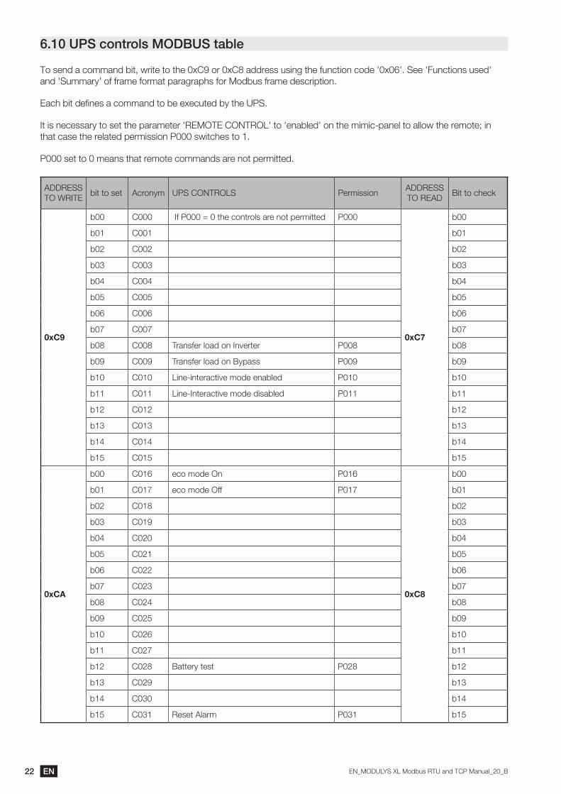
6.10 UPS controls MODBUS table
To send a command bit, write to the 0xC9 or 0xC8 address using the function code '0x06'. See 'Functions used' and 'Summary’ of frame format paragraphs for Modbus frame description.
Each bit defines a command to be executed by the UPS.
It is necessary to set the parameter 'REMOTE CONTROL' to 'enabled' on the mimic-panel to allow the remote; in that case the related permission P000 switches to 1.
P000 set to 0 means that remote commands are not permitted.
ADDRESS TO WRITE
bit to set Acronym UPS CONTROLS PermissionADDRESS TO READ
Bit to check
0xC9
b00 C000 If P000 = 0 the controls are not permitted P000
0xC7
b00
b01 C001 b01
b02 C002 b02
b03 C003 b03
b04 C004 b04
b05 C005 b05
b06 C006 b06
b07 C007 b07
b08 C008 Transfer load on Inverter P008 b08
b09 C009 Transfer load on Bypass P009 b09
b10 C010 Line-interactive mode enabled P010 b10
b11 C011 Line-Interactive mode disabled P011 b11
b12 C012 b12
b13 C013 b13
b14 C014 b14
b15 C015 b15
0xCA
b00 C016 eco mode On P016
0xC8
b00
b01 C017 eco mode Off P017 b01
b02 C018 b02
b03 C019 b03
b04 C020 b04
b05 C021 b05
b06 C022 b06
b07 C023 b07
b08 C024 b08
b09 C025 b09
b10 C026 b10
b11 C027 b11
b12 C028 Battery test P028 b12
b13 C029 b13
b14 C030 b14
b15 C031 Reset Alarm P031 b15

23ENEN_MODULYS XL Modbus RTU and TCP Manual_20_B
6.11 UPS date and time MODBUS table (0x00CB – 4 Words)
To update UPS date and time, write to addresses 0x00CB to 0x00CE using as a 'Function' the code '0x10'.
See 'Functions used' and 'Summary’ of frame format' paragraphs for Modbus frame description.
Address DescriptionValue
RemarksMSB LSB
0x00CB Minutes & Seconds Minute: 0 - 59 Seconds: 0 - 59 read / write
0x00CC Day & hours Day: 1 - 31 Hours: 0-23 read / write
0x00CD Month & day of the week Month: 1 - 12 1= Monday --- 7=Sunday read / write
0x00CE Year Year = value + 2000 read / write
Date and hours frame detail:
0x00CB 0x00CC 0x00CD 0x00CE
Minutes Second Day Hours Month Day/week Year + 2000
6.12 External battery monitoring report (Li-ION battery BMS connection)
ACRON. lsb of address DATA FORMAT
B000 0xB0 (MSB) = nb of strings / (lsb) = battery string selection READ
B000 0xB0 Set battery string number to read WRITE
The battery access level defines the MSB of the address:
- For shared battery at system level the access level MSB address is 0x00
- For shared battery at unit level the access level MSB address is 0xu0 (u = Unit number)
- For distributed batteries between modules the access level MSB address is: 0x(8+u)n with n=battery number to
read the data. Cf Battery data access table.
Sequence to access to Battery String data:
1. Write the battery string number to read 0xB0
2. The UPS populates the Battery table with the data of the string number requested
3. Read the battery string data starting at address 0xB1.
ACRON. lsb address DATA for battery strings (>= 1) DATA for Battery (string nb = 0)
B001 0xB1
General String status
0 = good
1 = weak
2 = failed
General Battery status
0 = good
1 = weak
2 = failed
B002 0xB2 String Voltage Battery voltage
B003 0xB3 String Impedance or SOH if Li-Ion battery
B004 0xB4 String Current Battery current
B005 0xB5 (MSB) = Max tem. / (lsb) = min tem.
B006 0xB6 Number of battery blocks OK Number of battery strings OK
B007 0xB7 Number of battery blocks WEAK Number of battery strings
B008 0xB8 Number of battery blocks FAILED Number of battery strings

24 EN EN_MODULYS XL Modbus RTU and TCP Manual_20_B
7. MODBUS PROTOCOL
7.1 Functions used
0x03 READ data
0x06 WRITE command or one word
0x10 Set UPS Clock – write several words
7.2 Summary of MODBUS frame formatFunction 0x03: bytes frame description
Slave Function Address Length CRC
10x03
MSB lsb MSB lsb MSB lsb
By default Address Number of words Compute
UPS slave answer
Slave Function Nb bytes Data Word0 Word1 … CRC
1 0x032 * nb of words
MSB lsb MSB lsb
Values …. Compute
Function 0x06: bytes frame description
Slave Function Address Data CRC
10x06
MSB lsb MSB lsb MSB lsb
By default Address Value to write Compute
UPS slave answer
Slave Function Address Data CRC
1 0x06MSB lsb MSB lsb MSB lsb
Address Value written Compute
Function 0x10: bytes frame description
Slave Function Address Length word Length Data CRC
10x10
MSB lsb MSB lsb MSB lsb MSB lsb
By default AddressNumber of words
to writeNumber of
bytesValues to write Compute
UPS slave answer
Slave Function Address Length CRC
1 0x10MSB lsb MSB lsb MSB lsb
Address Nb of words written Compute

25ENEN_MODULYS XL Modbus RTU and TCP Manual_20_B
8. MODBUS TCP IDA SPECIFICATION The frames below are only examples:
REQUEST FROM MASTER MODBUS TCP
Original frame: 01 03 1034 0003 40C5Encapsulated frame: 0046 0000 0006 01 03 1034 0003
Where:
0046 corresponds to the transaction number
0000 corresponds to the protocol identifier
0006 corresponds to the number of bytes (length of the message)
Note: the CRC is removed in the encapsulated MODBUS frame. REPLY FROM THE UPS MODBUS TCP:
Original frame: 01 03 06 0002 0184 0000 1960Encapsulated frame: 0046 0000 0009 01 03 06 0002 0184 0000
Where:
0046 corresponds to the transaction number
0000 corresponds to the protocol identifier
0006 corresponds to the number of bytes (length of the message)
Note: the CRC is removed in the encapsulated MODBUS frame.
9. MODBUS TCP AGILIPLUG FINDER TOOLHow to get the IP address of MODBUS TCP interface:
1. Download the tool from SOCOMEC’s WEB site
2. Unzip and copy the folder computer under Windows
3. Execute AGILIPLUG Finder executable file.
All MODBUS TCP Interface connected to network are listed in the application.
Check MAC address and open user interface using web browser and right IP address.
The device name in the tool indicates the type of interface: Digi Connect ME or AGILIPLUG
26 EN EN_MODULYS XL Modbus RTU and TCP Manual_20_B
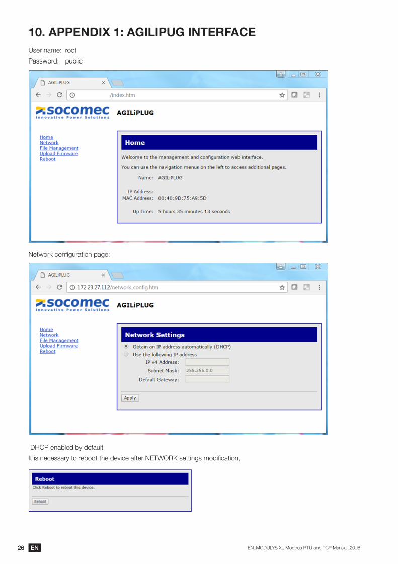
10. APPENDIX 1: AGILIPUG INTERFACEUser name: root
Password: public
Network configuration page:
DHCP enabled by default
It is necessary to reboot the device after NETWORK settings modification,
27ENEN_MODULYS XL Modbus RTU and TCP Manual_20_B
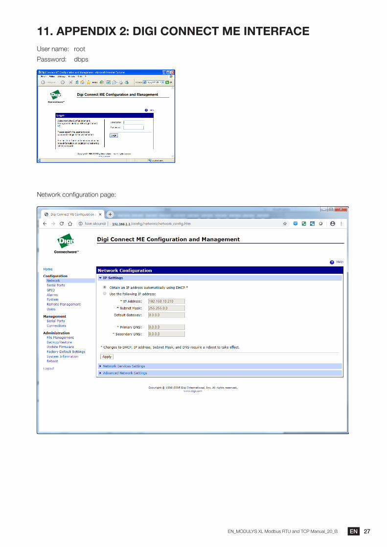
11. APPENDIX 2: DIGI CONNECT ME INTERFACEUser name: root
Password: dbps
Network configuration page:

Non
con
trac
tual
doc
umen
t. ©
202
1, S
ocom
ec S
AS
. All
right
s re
serv
ed. -
Doc
umen
t prin
ted
on p
aper
from
sus
tain
ably
man
aged
fore
sts.
Socomec: our innovations supporting your energy performance
The specialist for critical applications
Your power management expert
10 % of sales revenue dedicated to R&D
• Energy quality• Energy availability• Energy storage
400 experts dedicated to service provision
• Prevention and repairs• Measurement and analysis• Optimisation• Consultancy, commissioning
and training
1 independent manufacturer
• Control, command of LV facilities
• Safety of persons and assets
3,600 employees worldwide
• Measurement of electrical parameters
• Energy management
A worldwide presence
80 countries where our brand is distributed
12 production sites• France (x3)• Italy (x2)• Tunisia• India• China (x2)• USA (x3)
28 subsidiaries and commercial locations• Algeria • Australia • Belgium • China • Canada • Dubai (United Arab Emirates) • France • Germany • India • Indonesia • Italy • Ivory Coast • Netherlands • Poland • Portugal • Romania • Serbia • Singapore • Slovenia • South Africa • Spain • Switzerland • Thailand • Tunisia • Turkey • UK • USA
POWERCONVERSION
POWERMONITORING
POWERSWITCHING
EXPERTSERVICES
HEAD OFFICE
SOCOMEC GROUPSAS SOCOMEC capital 10 749 940 €R.C.S. Strasbourg B 548 500 149 B.P. 60010 - 1, rue de Westhouse F-67235 Benfeld CedexTel. +33 3 88 57 41 41 - Fax +33 3 88 57 78 [email protected]
YOUR DISTRIBUTOR / PARTNER
www.socomec.com