
DLMS MODBUS GATEWAY CONFIGURATION SOFTWARE
24
DLMS MODBUS GATEWAY CONFIGURATION SOFTWARE • MDC100E/G/W DLMS MODBUS GATEWAY 08 / 2021 MIKRODEV_SM_MDC100_EN_v1.0
-
Upload
khangminh22 -
Category
Documents
-
view
0 -
download
0
Transcript of DLMS MODBUS GATEWAY CONFIGURATION SOFTWARE

DLMS MODBUS GATEWAY
CONFIGURATION SOFTWARE
• MDC100E/G/W
DLMS MODBUS GATEWAY
08 / 2021
MIKRODEV_SM_MDC100_EN_v1.0

1
DLMS MODBUS GATEWAY- CONFIGURATION SOFTWARE
CONTENT
1 MODE C GATEWAY CONFIGURATION SOFTWARE ................................................. 6
1.1 General Information .................................................................................. 6
1.2 Device Connection ..................................................................................... 7
1.2.1 USB Serial Connection .................................................................................................... 7
1.2.2 TCP Connection – Device Discovery Mode ..................................................................... 8
1.2.3 TCP Connection – Manual ............................................................................................... 9
1.2.4 Port Numbering ............................................................................................................ 10
1.3 Offline Settings ........................................................................................11
2 MODE C GATEWAY Settings .............................................................................12
2.1 Status Tab ...............................................................................................12
2.2 Basic Settings ..........................................................................................13
2.3 Gateway General Settings .........................................................................14
2.4 Loading Settings to Device ........................................................................15
3 MODE C GATEWAY PARAMETER SETTINGS ........................................................17
3.1 Adding Meters ..........................................................................................17
3.2 Adding OBIS Codes ..................................................................................19
3.3 Adding OBIS Codes with Special Commands ................................................20
3.4 MODBUS Adress Table ..............................................................................21
3.5 Terminal .................................................................................................23

2
DLMS MODBUS GATEWAY- CONFIGURATION SOFTWARE
FIGURES
Figure 1 USB Connection ........................................................................................ 7
Figure 2 TCP Device Discovery ................................................................................ 8
Figure 3 TCP Connection ......................................................................................... 9
Figure 4 Version Query ..........................................................................................10
Figure 5 Response of Version Query ........................................................................10
Figure 6 Offline Device Selection ............................................................................11
Figure 7 Status Screen ..........................................................................................12
Figure 8 Basic Settings ..........................................................................................13
Figure 9 Gateway General Settings .........................................................................14
Figure 10 Load Settings .........................................................................................15
Figure 11 Loading Finished ....................................................................................15
Figure 12 Serial Connection Reset ..........................................................................16
Figure 13 TCP Connection Reset .............................................................................16
Figure 14 Protocol Flow Diagram ............................................................................18
Figure 15 Adding Obis Code ...................................................................................19
Figure 16 Adding Special Command ........................................................................20
Figure 17 MODE C Adress Table..............................................................................21
Figure 18 Modbus Address List Figure .....................................................................22
Figure 19 Terminal Command Window ....................................................................23

3
DLMS MODBUS GATEWAY- CONFIGURATION SOFTWARE
Preface
Mikrodev DLMS Modbus Gateway, creates a gateway between meters with IEC
62056-21 MOD-C and Modbus networks.
It can work as Client or Server (Client / Server) in TCP / IP Connection, without depending on
socket type specified in Modbus protocol. At this point, it is possible to provide access to the
devices over the internet when port routing is not possible. It also provides multiple
connection support for TCP socket connections and can serve up to 4 different TCP Master
devices over the same port.
The Mikrodev MDC100 Series converter is programmed using the Assistant Program.
Please follow our site www.mikrodev.com for the current version of the document.

4
DLMS MODBUS GATEWAY- CONFIGURATION SOFTWARE
About Mikrodev
Since 2006, MIKRODEV has been developing and manufacturing industrial control and
communication products. MIKRODEV serves the system integrators in the public and
private sector, OEM and end users.
Our products are manufactured complying with the quality standards required by the
industrial automation industry and the quality of our products are proved on the field for
many years
MIKRODEV is one of the few companies in the world that has its own designed IEC
61131-3 compliant library for its programmable logic control devices. In addition, the
open, flexible, programmable SCADA solution developed by MIKRODEV is also available
to customers.
MIKRODEV products' performance and wide range of applications make them possible for
customers to achieve faster, simplified and cost-effective results.

5
DLMS MODBUS GATEWAY- CONFIGURATION SOFTWARE
Warning!
✓ Use the programming editor only for Mikrodev Certifed devices
✓ When you change your physical hardware configuration, update your development
to the appropriate version.
✓ The developed program should be tested separately before taking to field service
and should be shipped to the field after the tests are successfully completed.
✓ Take all accident prevention measures and safety measures identified by local law
Failure to comply with these rules may result in death, serious injury or
property damage

6
DLMS MODBUS GATEWAY- CONFIGURATION SOFTWARE
1 MODE C GATEWAY CONFIGURATION SOFTWARE
1.1 General Information
The Assistant software is used to make all necessary settings for the Mikrodev Gateway
devices. Thanks to the software, device settings can be made online and/or offline. The
settings that are loaded on the device can easily be downloaded and the previously saved
settings can easilly be uploaded into the device by the program.
The connection between the program and the device can be established in various ways
such as USB, Ethernet, GSM, Wi-Fi. For Ethernet supported devices; there is also the ability
to search the network and list details with connection information.
1

7
DLMS MODBUS GATEWAY- CONFIGURATION SOFTWARE
1.2 Device Connection
1.2.1 USB Serial Connection
One of the methods for establishing communication between PC and Mikrodev device in
device configuration is USB serial connection. In order to perform USB connection
between PC and device, you need to install USB driver for PCs with Windows 7/8 / 8.1
operating systems. There is no need to install the USB driver for Windows 10 operating
systems. For serial connection over USB, “Connect over USB" box in the Connect and
Configure Your Device section of the Assistant software is selected. In the USB Port
Selection section, you should select the port and click "Connect". USB connection will be
established after that. (Figure 1)
Figure 1 USB Connection

8
DLMS MODBUS GATEWAY- CONFIGURATION SOFTWARE
1.2.2 TCP Connection – Device Discovery Mode
"Network Discovery" option is used to detect and connect IP addresses of Mikrodev
devices which are active in the local network. The "Network Discovery " box will be
highlighted after the "Connect via TCP" box is checked in the Connect and Configure to
Device section of the Assistant software. After clicking "Scan Network for Mikrodev
Devices", the serial number, IP address, listening port and software versions of all
Mikrodev devices which are active in the network are listed on the screen. (Fig. 2) You
can connect the device on the list by double clicking on the device name on the screen.
Figure 2 TCP Device Discovery

9
DLMS MODBUS GATEWAY- CONFIGURATION SOFTWARE
1.2.3 TCP Connection – Manual
When manually entering the ip address and port number of the device that is active in
the local network, "Manual" option is used. The "Manual" box is checked after the
"Connect over TCP" checkbox is checked in the Connect and Configure Device section
from the Assistant software. The IP address of the device to be connected is entered into
the "Device IP" section, the port number is entered into the "Port" section and "Connect"
is clicked. (Figure 3) Assistan software connects to the Mikrodev device with specified ip
address and port number.
Figure 3 TCP Connection
10
DLMS MODBUS GATEWAY- CONFIGURATION SOFTWARE
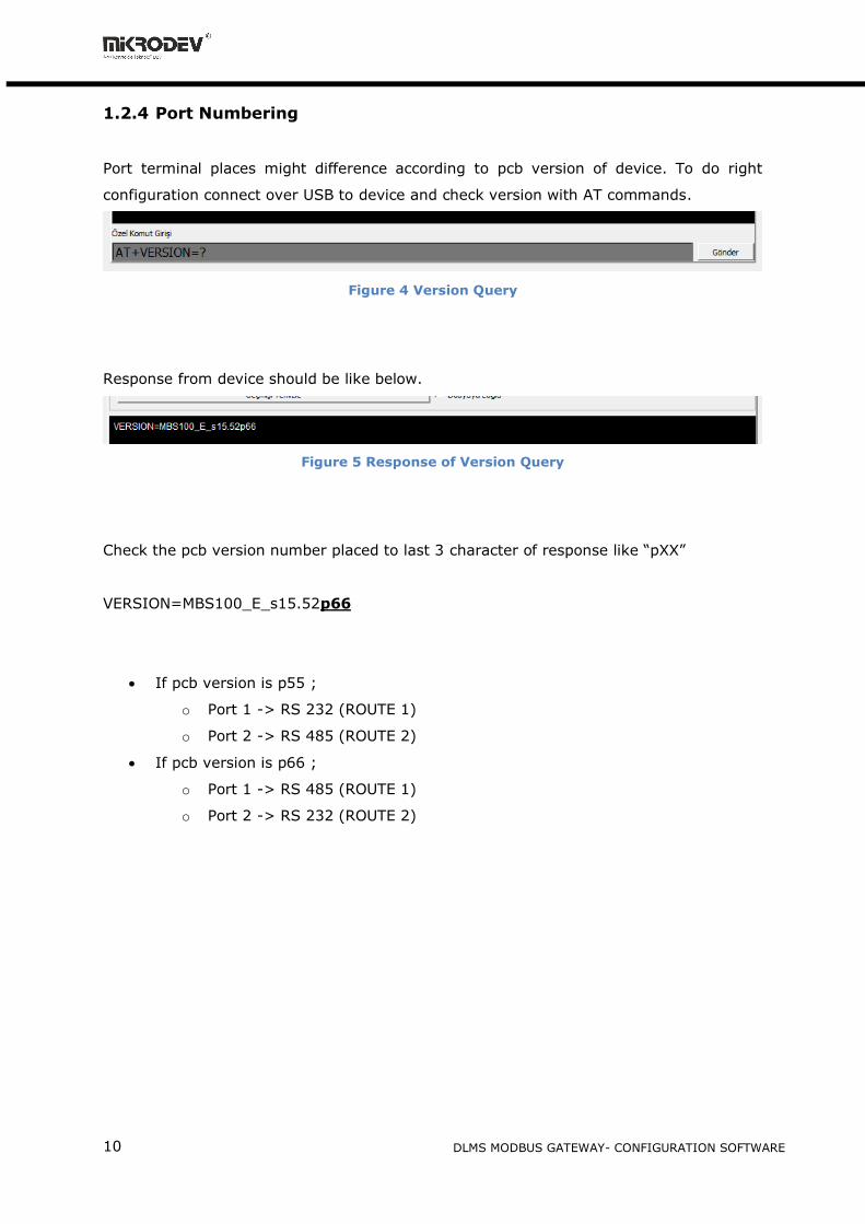
1.2.4 Port Numbering
Port terminal places might difference according to pcb version of device. To do right
configuration connect over USB to device and check version with AT commands.
Figure 4 Version Query
Response from device should be like below.
Figure 5 Response of Version Query
Check the pcb version number placed to last 3 character of response like “pXX”
VERSION=MBS100_E_s15.52p66
• If pcb version is p55 ;
o Port 1 -> RS 232 (ROUTE 1)
o Port 2 -> RS 485 (ROUTE 2)
• If pcb version is p66 ;
o Port 1 -> RS 485 (ROUTE 1)
o Port 2 -> RS 232 (ROUTE 2)

11
DLMS MODBUS GATEWAY- CONFIGURATION SOFTWARE
1.3 Offline Settings
Offline mode is used when parameter settings are made and saved without connecting to
the device. Click on "Click here for offline configuration" on the Assistant main screen
when you want to make the offline parameter settings. The device is selected in the
screen that appears, and then "Select this device" is clicked. (Fig. 6) Offline parameter
settings of the selected device can be made. In addition, using the "Load from
configuration file" option on the same page, previously saved configuration values can
also be loaded to the program.
Figure 6 Offline Device Selection

12
DLMS MODBUS GATEWAY- CONFIGURATION SOFTWARE
2 MODE C GATEWAY Settings
2.1 Status Tab
It is the status information screen which shows related information to the connected
Mikrodev device. This screen contains the device's manufacturing information, Ip settings
and serial connection settings (RS-485, RS-232). (Fig. 7) You can access the web
interface of the device from this screen as well. Select "Click here to access the web
interface of the device" to access the web interface.
Figure 7 Status Screen
2

13
DLMS MODBUS GATEWAY- CONFIGURATION SOFTWARE
2.2 Basic Settings
In the basic settings section, parameter set values are entered according to
communication types. For Ethernet connection enter the local ip, gateway ip, subnet and
for GSM connection enter the APN, user name, user password. SSID (Modem user name)
and password are entered when wifi connection is requested. In addition; the password
definition for access control to the Mikrodev device is performed on this page. In
addition, device connection follow-up duration, auto reset duration, and configuration
port can be entered. You can send ID after connection by checking the "Send ID after
connection" checkbox. (Figure 8)
Figure 8 Basic Settings

14
DLMS MODBUS GATEWAY- CONFIGURATION SOFTWARE
2.3 Gateway General Settings
In the Gateway General Settings section, the Modbus communication settings of the
Mikrodev device are made. In case of connection via Modbus TCP, server or client selection
of the connection type is made and port settings are defined. And also, Modbus Slave ID
settings are defined.
Figure 9 Gateway General Settings

15
DLMS MODBUS GATEWAY- CONFIGURATION SOFTWARE
2.4 Loading Settings to Device
Click "Device Management" on the Assistant software to send the configuration settings
to the device. Then click "Send Configuration" option. (Figure 10)
Figure 10 Load Settings
After completing the configuration, the device must be rebooted in order to register the
settings. (Figure 11)
Figure 11 Loading Finished

16
DLMS MODBUS GATEWAY- CONFIGURATION SOFTWARE
Restart the device by clicking "Restart Device" under "Device Management" on the main
screen of the Assistant program. When the device is rebooted, you may need to remove
and reinsert the USB cable to reconnect with the serial port. (Figure 12)
Figure 12 Serial Connection Reset
The TCP connection between the device and the PC will be established automatically after
the device is rebooted, after waiting approximately 20 seconds to reconnect to the device
through the TCP connection. (Figure 13)
Figure 13 TCP Connection Reset

17
DLMS MODBUS GATEWAY- CONFIGURATION SOFTWARE
3 MODE C GATEWAY PARAMETER SETTINGS
3.1 Adding Meters
MODE C Gateway support addressing mode or non-adressing boardcasting mode. If you
want to read meter without addressing, you should give 0 into Meter Serial No. if not you
should give serial number for addressing.
Meter Serial Prefix
For Example;
serial no: KLM51230012, prefix is
KLM
Meter Serial No
For Example;
serial no: KLM51230012, serial no is
51230012
when write 0 into this area, Gateway
work as boardcast addressing.
Starting Baudrate:
Look at Hata! Başvuru kaynağı
bulunamadı.
MODE C Baudrate:
Look at Hata! Başvuru kaynağı
bulunamadı.
SeriPort Mux:
Gateway has 1 RS485 port and 1
RS232 port. You can add meters over
both interfaces.
Data Bit:
Serial Communication Parameter
Parity Bit:
Serial Communication Parameter
Stop Bit:
Serial Communication Parameter
3

18
DLMS MODBUS GATEWAY- CONFIGURATION SOFTWARE
After all settings are made, click "Add Meter". If you want to add more than one meter, click
"Add and Continue Meter" option. Here you can add new meters in succession.
Starting
Baudrate
Protocol
MODE C
Baudrate
Figure 14 Protocol Flow Diagram

19
DLMS MODBUS GATEWAY- CONFIGURATION SOFTWARE
3.2 Adding OBIS Codes
To define the OBIS codes to be read out from the electricity meters, first click on the meter
from the list of defined meters. Then click "Add OBIS Code to Selected Meter " on the MODE
C Settings page. The OBIS value to be read is entered in the "OBIS Name" section in the
opened page. (Eg 0.0.0, 1.8.0, ...) In the "Code 1 Type" section, the variable type of the value
from the relevant OBIS code is selected. If more than one value is read from an OBIS code
to be defined, the variable type of the second value to be read is selected in the "Code 2
Type" section. (Figure 15)
Figure 15 Adding Obis Code
After all settings are made, click "Add OBIS". If more than one OBIS code is to be defined,
the "Add and Continue OBIS" option is clicked. Here you can add new OBIS codes in
succession.
If you want to modify the OBIS codes created in the MODE C OBIS Codes list, you can click
on the parameter to be modified and make changes.

20
DLMS MODBUS GATEWAY- CONFIGURATION SOFTWARE
3.3 Adding OBIS Codes with Special Commands
Special instructions may be required to read certain information on the electricity meters. In
such cases, the specific command information must be requested from the electricity meter's
manufacturer. In order to add OBIS code with special command, click "Add Programming
Mode Command to Selected Meter" option on the MODE C Settings page. In the incoming
screen, special command input is entered in the "Command" section. (Figure 16)
Figure 16 Adding Special Command
After all settings are made, click "Add Command". If more than one custom command will be
added, the "Add Command and Continue" option is clicked. You can add successive OBIS
codes in this way.
MODE C If you want to change the special commands created in the Meter Programming
Mode Commands list, you can click on the parameter to be changed and make changes.

21
DLMS MODBUS GATEWAY- CONFIGURATION SOFTWARE
3.4 MODBUS Adress Table
MODBUS address table shows the type of OBIS codes defined earlier and corresponding
modbus addresses. (Figure 17)
Figure 17 MODE C Adress Table
Addresses in the Modbus Address Table start at 10,000. The first two addresses of each
counter added to the table represent error counter and rx counter values.

22
DLMS MODBUS GATEWAY- CONFIGURATION SOFTWARE
When adding new OBIS code definitions it should be noted that; when multiple meters are
defined on the system, if a new OBIS code value is defined on the first meter, the modbus
addresses of the latter meters also change. For this reason, it is necessary to go through the
next meter after defining all the parameters of the previous meters completely. (Figure 18)
Figure 18 Modbus Address List Figure

23
DLMS MODBUS GATEWAY- CONFIGURATION SOFTWARE
3.5 Terminal
Terminal window is the section where the commands for the MMS100 series converters are
entered. In this section, information coming from the device is displayed on the screen. In the
"Custom Command Input" section, type the command to be queried (eg AT + VERSION =?)
And click "Send" to send the query to the device. The query answer appears on the screen.
(Figure 19) Click on "Clear History" in the "Console Window" section to clear the queries that
are displayed on the screen.
Figure 19 Terminal Command Window


![u[sonic] Modbus - Lambrecht meteo](https://static.fdokumen.com/doc/165x107/6334bd04a6138719eb0b33dc/usonic-modbus-lambrecht-meteo.jpg)


