model usb-dio-48 usb 48 channel digital input/output module ...

UnderstandingI2C, Firewire and USB
protocolGroup 1:
Dat Nguyen TienTan Tran NgocPhap Hoang VanTung Le Van
Bach Khoa Ha Noi 24/05/131
OutlineI2C protocol.Firewire protocol.USB protocol.Conclusion.
2

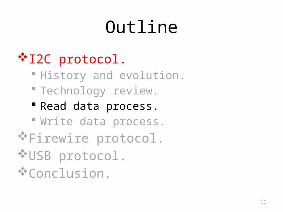
OutlineI2C protocol.
History and evolution. Technology review. Read data process. Write data process.
Firewire protocol.USB protocol.Conclusion.
3

OutlineI2C protocol.
History and evolution. Technology review. Read data process. Write data process.
Firewire protocol.USB protocol.Conclusion.
4

History and evolution.I²C: Inter-Integrated Circuit.Developed and patented by Philips for connecting low speed peripherals to a motherboard, embedded system or cell phone.
Version: Version Date FeatureOriginal 1982 Standard mode:
Speed: 100 kHz7-bit addressing.
V 1.0 1992 Add Fast-mode:Speed: 400 kHz
10-bit addressingV 2.0 1998 Add High-speed mode:
3.4 MHzV 3.0 2007 Add Fast-mode +: 1 MHzV 4.0 2012 Add Ultra Fast-mode: 5
MHz5

OutlineI2C protocol.
History and evolution. Technology review. Read data process. Write data process.
Firewire protocol.USB protocol.Conclusion.
6

Technology review - Characteristic.
Synchronous serial.Half-duplex.7-bits and 10-bits addressing mode.6 mode:
Low-speed mode: 10 kbps. Standard-mode: 100 kbps. Fast-mode: 400 kbps. Fast-mode+: 1 Mbps. High-speed mode: 3,4 Mbps. Ultra Fast-mode: 5 Mbps.
The bus is a multi-master bus.7

Technology review - System overview.
8

Technology review - System overview.
2 roles for nodes: master and slave. Master node generates the clock and initiates communication with slaves.
Slave node receives the clock and responds when addressed by the master.
9

Technology review - System overview.
3 modes: One master – one slave. One master – multi-slave. Multi-master – multi-slave.
There are two potential operation: master transmit – slave receive. master receive – slave transmit.
10
OutlineI2C protocol.
History and evolution. Technology review. Read data process. Write data process.
Firewire protocol.USB protocol.Conclusion.
11

Read data process – Read 1 byte.
12

Read data process – Read multi bytes.
13

OutlineI2C protocol.
History and evolution. Technology review. Read data process. Write data process.
Firewire protocol.USB protocol.Conclusion.
14

Write data process – 1 byte.
15

Write data process – multi byte.
16

OutlineI2C protocol.Firewire protocol.
What is Firewire. Feature. Catergory.
USB protocol.Conclusion.
17
What is Firewire?FireWire is the high speed serial communication standard for bus computer.
It’s also has name is IEEE-1394.It was developed by Apple and Texas Instruments mainly for use with video and audio demands in both Macs and PCs.
18

Feature.Support Plug and Play.It has the capability of "hot plugging" .
Peer – to – peer connection.Maximum of number devices on the bus is 63.
19

Catergory.Firewire 400 (IEEE1394 – 1995).Enhancements (IEEE1394a – 2000).
Firewire800 (IEEE1394b – 2002).FireWire S1600 and S3200.Firewire S800T (IEEE1394c – 2006).
20

Firewire 400 (IEEE1394 – 1995).
It can transfer data between devices at 100, 200, or 400 Mbit/s half-duplex data rates.
Cable length is limited to 4.5 m with 6-conductor connector.
21

Enhancements (IEEE1394a – 2000).
Improved the original specification.
It added support for asynchronous streaming, quicker bus reconfiguration, packet concatenation, and a power-saving suspend mode.
Standardized the 4-conductor connector that is fully data-compatible with 6-conductor. 22

Firewire800 (IEEE1394b – 2002)
It can transfer data between devices at 800 Mbit/s half-duplex data rates, support data rates up to 3,2Gbps.
Cable length is limited to 100 m with 9-conductor connector
23

FireWire S1600 and S3200
Support data rates up to 1,6Gbps with S1600 and 3,2Gbps with S3200.
Use the same 9-conductor beta connectors as the existing FireWire 800 and are fully compatible with existing S400 and S800 devices.
It competes with USB 3.0.24

Firewire S800T (IEEE1394c – 2006)
Provides 800 Mbps over the same Ethernet connectors with Category 5e cable.
25

OutlineI2C protocol.Firewire protocol.USB protocol.
History and evolution. Technology review. USB system overview. USB communication flow. USB Protocol.
Conclusion.26

OutlineI2C protocol.Firewire protocol.USB protocol.
History and evolution. Technology review. USB system overview. USB communication flow. USB Protocol.
Conclusion.27

History and evolution.Why we create USB?
We want to use one interface for many devices.
We want plug and play without rebooting.
USB protocol was developed: USB—Universal Serial Bus. Invented and standardized by a group of computer and peripherals manufactures in 1995.
Compete with IEEE1394. 28

History and evolution.Versions of USB
Release version
date speed
USB 1.1 Aug 1998 1,5 Mbps (Low-speed)
12 Mbps (Full-speed)
USB 2.0 Apr 2000 1,5 Mbps (Low-speed)
12 Mbps (Full-speed)
480 Mbps (High-speed)
USB 3.0 Nov 2008 4,8 Gbps (Super-speed)
USB 3.1 July 2013 10 Gbps (Super-speed+)
29

OutlineI2C protocol.Firewire protocol.USB protocol.
History and evolution. Technology review. USB system overview. USB communication flow. USB Protocol.
Conclusion.30

Technology reviewCharacteristic:
Asynchronous serial. Half-duplex. Maximum number of devices: 127. Maximum distance: 5m (up to 30m with 5 hubs).
Speed: support 4 kinds 1,5 Mbps, 12 Mbps, 480 Mbps, 4,8 Gbps.
Backwards-compatible.31

Technology review
32

Technology reviewAdvantages:
Ease of use:•One interface for many devices.•Automatic configuration: OS detects a device that is plugged in and tries to load device drivers for the device.
•Hot pluggable: peripheral devices can be plugged in and unplugged while the computer is running.
•Easy to connect.•No power supply required (sometimes): support 5V-500mA.
Fast and reliable data transfer:•USB 3.0 support speed up to 4,8 Gbps.•Designed for minimize data errors.
Low-cost. Low Power Consumption: automatically power down USB peripherals when not use.
Disadvantages: USB is more complex than earlier protocols.
33

OutlineI2C protocol.Firewire protocol.USB protocol.
History and evolution. Technology review. USB system overview. USB communication flow. USB Protocol.
Conclusion.34

USB system overview.USB physical topology: USB uses a tiered topology.
USB supports up to seven tiers, including a root tier and five non-root hubs.
3 kind devices: host (one), hub (option) and End Device (many).
35

USB system overview.USB logical topology: USB uses a star topology.
Hub and End Device are logical device.
36

USB system overview - Host.
Host: include Client SW, USB System SW (USB Driver, Host Controller Driver, host SW) and USB Host Controller.
The USB host is the coordinating entity for the USB. It controls all access to the USB. Therefore, a USB device gains access to the bus only through the host.
The USB host is also responsible for monitoring USB topology.
37

USB system overview - Hub.
Hub: one or more. It is optional in USB system. Like the hubs used for computer network.
Enables many devices to connect to a single USB port.
38

USB system overview - Device.
Device: Everything in the USB system, which is not a host, is a device ( include hubs). Has an unique address. Each device report information to assist the host in identification and configuration. 39

USB system overview - Cable.
Cable:pin Name Descryption1 Vcc +5 Vdc2 D- Data-3 D+ Data+4 GND Ground
40

OutlineI2C protocol.Firewire protocol.USB protocol.
History and evolution. Technology review. USB system overview. USB communication flow. USB Protocol.
Conclusion.41

USB communication flow.Three layer:
Physical layer.
Protocol Engine Layer.
Application Layer.
42

USB communication flow – Physical layer.
The layer of Host and Device communicate with each other through wire.
In Host, the layer include Host Controller block and SIE block. In Device, the layer only include SIE block.
43

USB communication flow – Physical layer.
USB wire: Logic level:
•Logic 1: D_ low & D+ high.•Logic 0: D_ high & D+ low.
Line code: NRZI (Non Return to Zero Inverted).•Want to transmit data = 1: not changing level of signal.
•Want to transmit data = 0: flip the value of the differential pair.
44

USB communication flow – Physical layer.
Host Controller: Ensure that everything which is transmitted on the bus is correct.
SIE: Serial Interface Engine. Serialization and Deserialization. Encoding and Decoding. Generate (for out) and Verify (for in) CRC.
Detect PID (Packet Identifier field).
45

USB communication flow – Protocol Engine Layer.
Translating the data between NO USB format and the USB format.
In Host, the layer include USB system SW. In Device, the layer include USB logical Device.
USB system SW communicate with USB logical Device through pipe.
46

USB communication flow – Protocol Engine Layer.
USB system SW: Compose of The Host Controller Driver and The USB Driver.
Responsible for bandwidth allocation and bus power management.
USB logical Device: Compose of a collection of independent endpoint.
Each endpoint has an unique Endpoint Number and is unidirectional (except endpoint zero and has two type: In/Out).
Default pipe is associated with endpoint zero.
47

USB communication flow – Protocol Engine Layer.
Pipe: Logic communication between Client SW on the Host and the Function on the Device (in Application layer).
Associate between a specific endpoint on the Device and the System SW on the Host (in Protocol Engine Layer).
48

USB communication flow – Application Layer.
In the Host, the layer include Client SW. Manages device interface by transferring data from its buffers to the endpoint with the appropriate interface.
In the Device, the layer include Function. Composed of interfaces and controls the functionality of the device.
49

OutlineI2C protocol.Firewire protocol.USB protocol.
History and evolution. Technology review. USB system overview. USB communication flow. USB Protocol.
Conclusion.50

USB Protocol.There are 4 transfer types.
Control Transfer. Isochronous Transfer. Bulk Transfer Interrupt Transfer
Each transfer type contains some USB transactions.USB transactions are done through phase (packets).Each transaction contains a token phase and may contain a data phase and/or handshake phase. Token phase: host initiates token indicating the future transfer type.
Data phase: actual data transmitted Handshake phase: indicate the success or failure of the transaction.
51
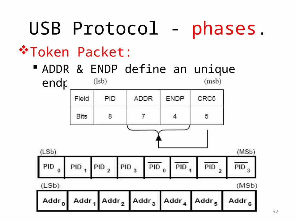
USB Protocol - phases.Token Packet:
ADDR & ENDP define an unique endpoint.
52

USB Protocol - phases.Data Packet:
53

USB Protocol - phases.Handshake Packet:
54

USB Protocol - phases.
55

USB Protocol - Control Transfer.
56

USB Protocol - Control Transfer.
Used to configure a device (enumeration) Compose of 3 transactions (setup, data, status).
57

USB Protocol - Isochronous Transfer.
58

USB Protocol - Isochronous Transfer.
Used for multimedia devices. It is guarantee the required bandwidth.
There 2 kinds transaction: IN or OUT. Each transaction hasn’t handshake phase.
59

USB Protocol - Bulk Transfer
60

USB Protocol - Bulk Transfer
Used for large burst data. Guarantee of delivery , no guarantee of bandwidth or minimum latency.
There 2 kinds transaction: IN or OUT. Each transaction has 3 phases.
61

USB Protocol - Interrupt.
62

USB Protocol - Interrupt. If there is a pending interrupt , the function will send details to host after host poll it.
There 2 kinds transaction: IN or OUT. Each transaction has 3 phases.
63
Copyright © 2022 FDOKUMEN