enCoRe™ II USB Bootloader - Infineon Technologies
18
www.infineon.com Please note that Cypress is an Infineon Technologies Company. The document following this cover page is marked as “Cypress” document as this is the company that originally developed the product. Please note that Infineon will continue to offer the product to new and existing customers as part of the Infineon product portfolio. Continuity of document content The fact that Infineon offers the following product as part of the Infineon product portfolio does not lead to any changes to this document. Future revisions will occur when appropriate, and any changes will be set out on the document history page. Continuity of ordering part numbers Infineon continues to support existing part numbers. Please continue to use the ordering part numbers listed in the datasheet for ordering.
-
Upload
khangminh22 -
Category
Documents
-
view
1 -
download
0
Transcript of enCoRe™ II USB Bootloader - Infineon Technologies

www.infineon.com
Please note that Cypress is an Infineon Technologies Company.The document following this cover page is marked as “Cypress” document as this is the company that originally developed the product. Please note that Infineon will continue to offer the product to new and existing customers as part of the Infineon product portfolio.
Continuity of document contentThe fact that Infineon offers the following product as part of the Infineon product portfolio does not lead to any changes to this document. Future revisions will occur when appropriate, and any changes will be set out on the document history page.
Continuity of ordering part numbersInfineon continues to support existing part numbers. Please continue to use the ordering part numbers listed in the datasheet for ordering.

THIS SPEC IS OBSOLETE
Spec No: 001-17190
Spec Title: AN6075 - ENCORE(TM) II USBBOOTLOADER
Sunset Owner: Madhura Tapse (MVTA)
Replaced By: None

www.cypress.com Document No. 001-17190 Rev. *E 1
AN6075
Encore™ II USB Bootloader
Author: Anandhakumar C
Associated Project: Yes
Associated Part Family: USB Low-Speed Peripherals – CY7C638xx, CY7C633xx
Software Version: PSoC® Designer™ 5.1 SP1
Related Application Notes: None
To get the latest version of this application note, or the associated project file, please visit http://www.cypress.com/go/AN6075.
Allowing end users to upgrade their products for bug fixes or feature enhancements is a desirable feature from both a
marketing and engineering perspective. enCoRe™ II, as a Flash-based microcontroller, has the potential to allow
firmware upgrades in the field via the USB protocol. However, firmware assistance is required to manage the download
of the new code from the USB host, re-program the Flash, and re-start operation under the new code. This application
note describes a bootloader for the low-speed USB enCoRe II device to implement this capability.
Contents
1 Introduction ............................................................... 1 2 Bootloader Operation ............................................... 2 3 Memory Map............................................................. 3 4 Bootloader Descriptors ............................................. 4 5 Application Descriptors ............................................. 4 6 USB Interrupt Vectors ............................................... 4 7 Sequence of Operation ............................................. 4
7.1 10-Byte Bootloader Key ................................... 5 7.2 64-Byte Data Packet ........................................ 6 7.3 Error Code Register ......................................... 6 7.4 Important Functions ......................................... 7
8 Flow Charts .............................................................. 7 8.1 Reset Operation ............................................... 8 8.2 bootLoaderStart ............................................... 9 8.3 bootLoader..................................................... 10
8.4 bootProcessFlashPage.................................. 11 9 Allocation of RAM and Location of USB APIs ......... 12 10 USB Interface ......................................................... 12 11 Creating a Project with USB Bootloader ................. 12 12 Program Flow for Host Device to Download Data to User Module .................................................................... 13 13 USB Downloader GUI Application .......................... 13 14 Summary ................................................................ 14 Document History ............................................................ 15 Worldwide Sales and Design Support ............................. 16 Products .......................................................................... 16 PSoC® Solutions ............................................................. 16 Cypress Developer Community....................................... 16 Technical Support ........................................................... 16
1 Introduction
It is convenient to change the running code in a device on site without physically replacing the device. To do this, bootloader code is programmed in a protected memory space in the enCoRe II and through this bootloader program, the user code is downloaded to the device. The bootloader uses USB to communicate with the downloading master.
All the routines required for the bootloader, the USB user module, the bootloader code, bootloader descriptors, and the flash block programming are contained in a protected area to prevent any data corruption and failure of the bootloader.

enCoRe™ II USB Bootloader
www.cypress.com Document No. 001-17190 Rev.*E 2
2 Bootloader Operation
The bootloader is located from 1200h. This memory space is write-protected to prevent any accidental modification or corruption. The reset vector is modified so that when the processor is reset, the bootloader executes first.
The bootloader carries out the following operations:
Upon reset, the bootloader calculates checksum for the user code and verifies it with a checksum written to the last two bytes of the Flash. If the two checksums match, it means that the previous bootloading attempt was successful and the bootloader branches to the beginning of the user code and the user code can execute.
If the checksums do not match, the bootloader executes a customizable user code to perform system critical tasks, such as turning on a fan and so forth, and then enters the bootloading mode.
It starts the bootloader USB device and waits until the PC enumerates. The device has an interrupt IN endpoint of 8 bytes and an interrupt OUT endpoint of 8 bytes. When enumeration is complete, the bootloader waits for a 64-byte packet containing a 10-byte bootloader key from the host.
If, due to some reason such as power transient, the previous bootloading failed, then the checksum verification fails and the program enters the bootloading mode.
Upon receiving a valid bootloader key from the host, the bootloader responds with a status byte informing the host that it is ready to receive the FLASH image.
The host sends the user code in 64-byte packets with some encoding bytes (explained in a later section).
The bootloader writes the user code to the Flash. When all the Flash pages are written successfully, it performs a Flash verify operation and then performs a software reset to start the user code.
The bootloader can also be entered from the user code. For this, the application has a command that is sent to the USB device while the application is running. Upon receiving this command over the application USB interface, the main application must stop all the resources, stop the USB, and then call the EnterBootLoader function. When the bootloader is entered, the bootloader device enumerates and the bootloading operation listed above is performed. The bootloader can also be entered by checking for some hardware status such as a switch. Upon sensing the switch press, the EnterBootLoader function is called. This bootloader function can also be called upon the reception of certain requests
from the host.

enCoRe™ II USB Bootloader
www.cypress.com Document No. 001-17190 Rev.*E 3
3 Memory Map
The memory map is shown in Figure 1.
The bootloader resides at Flash location 1200h. This is so the development of user code can be done with minimum modifications to the project settings.
The flashsecurity.txt file needs the following modifications:
All Flash blocks from 72 to 126 that contain the bootloader are write protected and have a setting of W.
The first two blocks that contain the reset vector and the USB vectors are also write protected with W. This protects the reset vector and the USB vectors from corruption.
Block 127 contains the Flash checksum of the user code in the last two bytes (1FFEh and 1FFFh). This block is set to field upgrade mode, R.
The protection level for all the other blocks is set to field upgrade, R, so that the user code can be written to them.
As the first two blocks are write protected, the interrupt vectors in these blocks are to be mapped to another unprotected location. The interrupt vectors are relocated to 80h. In the boot.tpl file, ljmp instructions are placed to branch to the
corresponding relocated vector. In the relocated vector, the command such as @INTERRUPT_25 is placed so that the application build process automatically places the name of the respective ISRs at the relocated address.
Following the relocated vectors at 100h, there are two blocks reserved for the application USB descriptors. These blocks are located at this fixed location so that the bootloader finds them when a new image is written to Flash. The allocated memory for the descriptors is changed by adjusting the following line in custom.lkp: -busb_desc:0x100.0x2FF. You must then change the ORG point for the following area called start from
300h to a new value to enlarge the descriptor area. Reducing the area conserves memory if the descriptors are reduced in size.
The address of __Start follows the descriptor table in the area called start.
Figure 1. Bootloader Memory Map
Modified Reset Vector and ISR
0000h
0080h
1200h
1FC0h 1FFFh
User Code
Bootloader Code
Checksum Page

enCoRe™ II USB Bootloader
www.cypress.com Document No. 001-17190 Rev.*E 4
4 Bootloader Descriptors
The file bl_descr.asm contains the descriptors for the bootloader. Before releasing the initial enCoRe II image, the bootloader descriptors are modified to contain the proper VID or PID to meet the customer’s needs. There are a few extra bytes in the bootloader section of memory for these descriptors to expand for different string lengths. Once the code is released, these descriptors cannot be updated via the bootloader protocol.
5 Application Descriptors
The application descriptors are updated using the USB Setup Wizard. This is done by right clicking on the USB user module in the Device Editor. When code generation is executed, the descriptors are generated and placed at 100h during linker execution.
6 USB Interrupt Vectors
As the USB interrupt vectors are shared by the bootloader and the application, there needs to be some mechanism by which the currently running configuration is checked and the proper ISR executed. For this, the bootloader contains the interrupt vectors for the USB interrupts. boot.tpl is modified to redirect some of the USB interrupts to USB handlers in bootloader. The USB handlers check for a 2-byte bootloader signature. This signature is stored in RAM. If the sequence of values in these locations matches the signature sequence defined in the bl_loader.inc file, then the interrupt is redirected to the bootloader ISR. If there is no signature found, it means that the user application is running and so control is transferred back to the newly relocated user code vector in boot.asm.
The signature sequence is modified by changing the SIGNATURE0 to SIGNATURE1 constants in bl_loader.inc.
The signature locations in the RAM are updated with the signature whenever the bootloader is entered either after a flash verification failure or from the user code.
7 Sequence of Operation
The sequence of operation is as follows:
1. Upon reset, RAM is checked for presence of a bootloader signature. This determines if the bootLoaderVerify has been reached after a power on reset or after the user code has generated a reset to enter bootloader. If the bootloader has to be invoked from the user code, the user code calls a function that programs the signature and generates a reset.
2. If RAM does not contain the signature, the checksum of the entire user code is compared with the checksum stored in 1FFEh and 1FFFh. If the checksums match, then the previous bootloading operation was successful and the program branches to __Start, from where the user code executes.
3. If the checksums do not match, then there is no user code present, or the previous bootloading operation failed. In this condition, the program writes the bootloader signature to RAM and enters the bootload mode, where the bootloader USB interface is started. The bootloader then waits for the host to enumerate and the program waits for a 10-byte bootloader key from the host.
4. Upon receiving a valid 10-byte bootloader key, the program waits for a 64-byte data packet from the host. During this wait, a timeout variable is decremented. When the host does not send a data packet within this timeout period, the program resets and again waits for the bootloader key. The timeout can be modified by changing the BOOT_TIMEOUT constant in bl_loader.inc. The sleep timer is used for timing. It is configured to run at 8 Hz. So for a timeout of 1 second, the value of BOOT_TIMEOUT is 8. For a BOOT_TIMEOUT value of 255, a timeout of 32 seconds is achieved.
5. When a 64-byte packet is received from the host, the bootVerifyPacketChecksum function is called to verify if the packet was received without error. If there is no packet checksum error, the operation indicated by the bootloader command (byte 2 of the 64-byte packet) is performed on the data. The host can send the following commands: Flash Write, Flash Verify, and Bootloader Exit. When the operation completes, a status byte is constructed to let the host know the status of the operation. The host waits for the status byte to be available in the IN endpoint before sending further data. If the host issued a Bootloader Exit command, then the user code checksum is verified and if valid, the BOOTLOAD_DONE flag is set.
enCoRe™ II USB Bootloader
www.cypress.com Document No. 001-17190 Rev.*E 5
6. The program then waits for the host to read the status byte. If the host does not read the status within the timeout period, the wait is timed such that a reset is performed.
7. After the host reads the status, the program checks the status byte to see if there was any error in the previous operation. If any error is detected (such as flash write error or packet checksum error), the program generates a reset.
8. Then the program checks if the BOOTLOAD_DONE flag is set in the status register. This flag indicates successful completion of the bootloading operation. If the flag is set, the program branches to __Start, from where the user code executes.
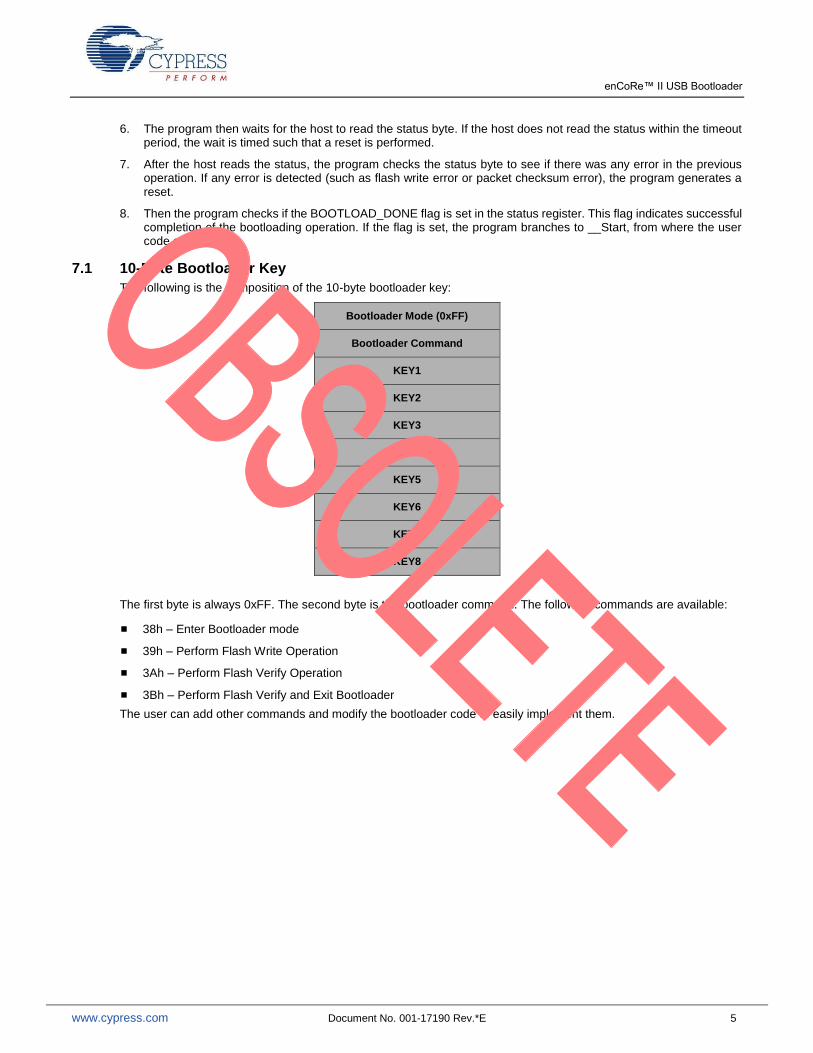
7.1 10-Byte Bootloader Key
The following is the composition of the 10-byte bootloader key:
Bootloader Mode (0xFF)
Bootloader Command
KEY1
KEY2
KEY3
KEY4
KEY5
KEY6
KEY7
KEY8
The first byte is always 0xFF. The second byte is the bootloader command. The following commands are available:
38h – Enter Bootloader mode
39h – Perform Flash Write Operation
3Ah – Perform Flash Verify Operation
3Bh – Perform Flash Verify and Exit Bootloader
The user can add other commands and modify the bootloader code to easily implement them.
enCoRe™ II USB Bootloader
www.cypress.com Document No. 001-17190 Rev.*E 6
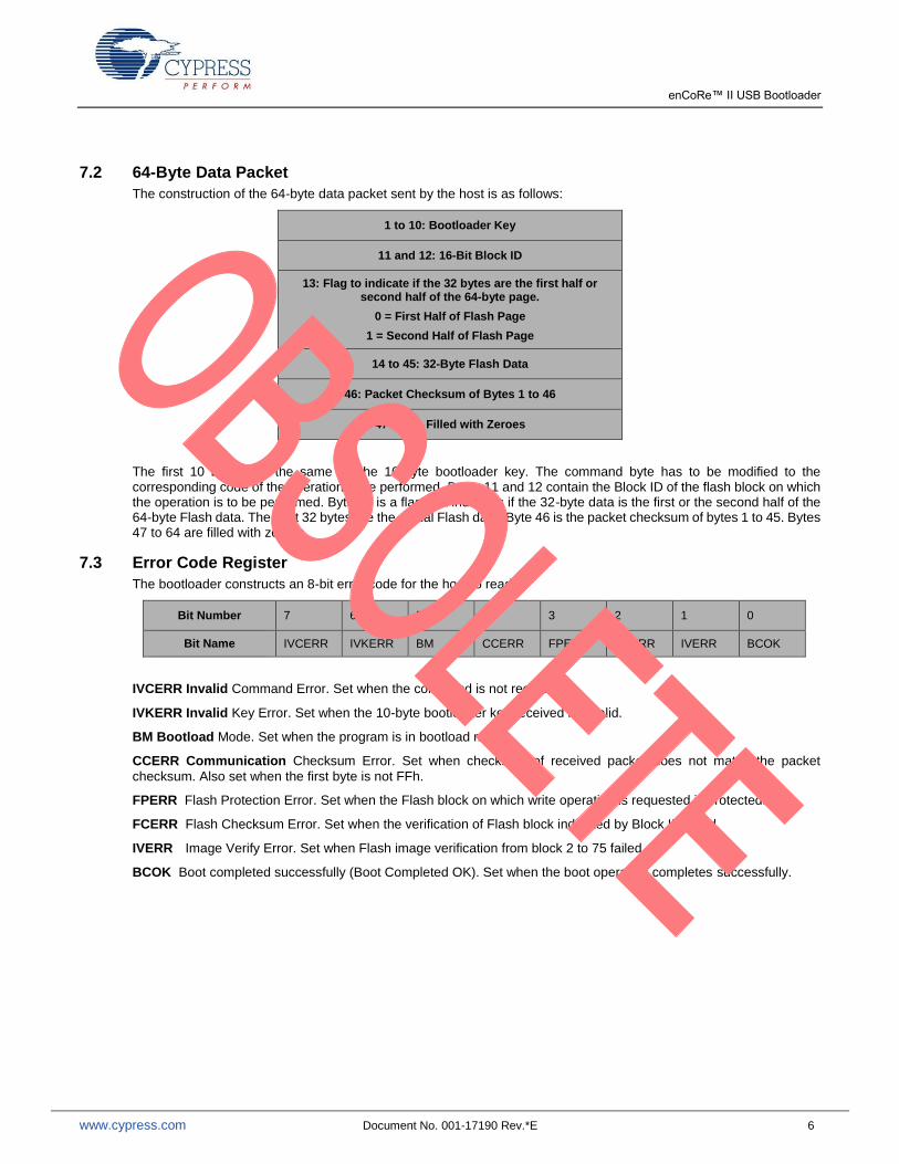
7.2 64-Byte Data Packet
The construction of the 64-byte data packet sent by the host is as follows:
1 to 10: Bootloader Key
11 and 12: 16-Bit Block ID
13: Flag to indicate if the 32 bytes are the first half or second half of the 64-byte page.
0 = First Half of Flash Page
1 = Second Half of Flash Page
14 to 45: 32-Byte Flash Data
46: Packet Checksum of Bytes 1 to 46
47 to 64: Filled with Zeroes
The first 10 bytes are the same as the 10-byte bootloader key. The command byte has to be modified to the corresponding code of the operation to be performed. Bytes 11 and 12 contain the Block ID of the flash block on which the operation is to be performed. Byte 13 is a flag that indicates if the 32-byte data is the first or the second half of the 64-byte Flash data. The next 32 bytes are the actual Flash data. Byte 46 is the packet checksum of bytes 1 to 45. Bytes 47 to 64 are filled with zeroes.
7.3 Error Code Register
The bootloader constructs an 8-bit error code for the host to read.
Bit Number 7 6 5 4 3 2 1 0
Bit Name IVCERR IVKERR BM CCERR FPERR FCERR IVERR BCOK
IVCERR Invalid Command Error. Set when the command is not recognized.
IVKERR Invalid Key Error. Set when the 10-byte bootloader key received is invalid.
BM Bootload Mode. Set when the program is in bootload mode.
CCERR Communication Checksum Error. Set when checksum of received packet does not match the packet
checksum. Also set when the first byte is not FFh.
FPERR Flash Protection Error. Set when the Flash block on which write operation is requested is protected.
FCERR Flash Checksum Error. Set when the verification of Flash block indicated by Block ID failed.
IVERR Image Verify Error. Set when Flash image verification from block 2 to 75 failed.
BCOK Boot completed successfully (Boot Completed OK). Set when the boot operation completes successfully.

enCoRe™ II USB Bootloader
www.cypress.com Document No. 001-17190 Rev.*E 7
7.4 Important Functions
The bootloader code is written in modules so that modification is easy. Functions are also written that perform specific tasks and modify specific bits in the Error Code register. The main bootloader calls these functions and tests the bits in error code to determine the status.
bootLoaderVerify: This is the entry point of the bootloader. The program first checks if RAM has the Bootloader signature. If a valid signature is found, the program directly branches to bootloaderStart. If there is no valid signature, the bootVerifyFlashChecksum function is called to verify the Flash image. Then the program checks the status register to find if the Flash checksum was successful. If successful, it branches to __Start for the user code to execute, or it calls the bootUserCode function where custom code performs the system critical tasks. Then it branches to bootLoaderStart where the bootloader operation starts.
bootUserCode: This function can be modified by the user to implement system critical tasks such as turning on a
fan or tripping relays in case of boot failure.
bootProcessFlashPage: This function processes the 64-byte packet received from the host. First it calls the bootVerifyBootLoaderKey to check the first 10 bytes for a valid bootloader key. If the key is valid, it performs the corresponding operation indicated by the command byte. Then it checks if the Flash packet is the first or the second half of the block. If the data is in the first half of the Flash page, it stores these 32 bytes in a buffer. If the data is in the second half of the Flash page, it stores the data in the buffer and then performs the operation requested by the command byte.
bootVerifyBootLoaderKey: This function checks the KEY1 to KEY8 bytes of the 10-byte bootloader key with a
predetermined pattern. If the patterns match, the IVKERR bit in the Error Code register is cleared. If the patterns do not match, the IVKERR bit is set.
bootVerifyPacketChecksum: This function calculates the checksum of the received packet from bytes 1 to 45.
Then it compares this calculated packet checksum with the packet sent by the host in byte 46. If the checksums match, the CCERR bit of the Error Code register is cleared. If the checksums do not match, the CCERR bit is set.
bootVerifyFlashChecksum: This routine calculates a two-byte checksum for the user code. The starting address of the user code is defined by the START_ADDRESS constant. The number of blocks of user code is defined by the NUMBER_OF_BLOCKS constant defined in bl_loader.inc. Then it compares this checksum with the checksum stored in locations 1FFEh and 1FFFh. If the checksums match, the IVERR bit in the Error Code register is cleared. If the checksums do not match, the IVERR bit is set.
8 Flow Charts
The following flow charts for key code modules provide additional information about the operation of the bootloader.
enCoRe™ II USB Bootloader
www.cypress.com Document No. 001-17190 Rev.*E 8
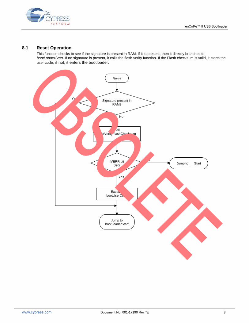
8.1 Reset Operation
This function checks to see if the signature is present in RAM. If it is present, then it directly branches to bootLoaderStart. If no signature is present, it calls the flash verify function. If the Flash checksum is valid, it starts the
user code; if not, it enters the bootloader.
Reset
Call bootVerifyFlashChecksum
IVERR bit Set?
Jump to __Start
Execute bootUserCode
Jump to bootLoaderStart
Yes
No
Signature present in RAM?
No
Yes

enCoRe™ II USB Bootloader
www.cypress.com Document No. 001-17190 Rev.*E 9
8.2 bootLoaderStart
This function initializes resources. It starts the USB and waits for enumeration to complete. It then waits for the 10-byte bootloader key. Upon receiving a valid bootloader key, it sets the Bootload Mode flag in status register and enters bootloader.
bootLoaderStart
Clear bootErrorCode Initialize CPU hardware
Reset
Yes
To bootLoader
TimeOut? Set IVCERR bit in Error Code
register
Command = Enter
Bootload?
Enable USB interface Wait for enumeration to complete
10-byte key Received?
byte #1 = FFh?
Verify Boot Loader key
IVKERR = 1?
Set CCERR bit in Error Code
register
Has Master
read the error
code?
Yes
Yes
Yes
No
No
No
No
No
No
Yes
Yes

enCoRe™ II USB Bootloader
www.cypress.com Document No. 001-17190 Rev.*E 10
8.3 bootLoader
This function performs the bootloader process.
A
Bootload Successful: Disable USB Disable Interrupts Clear the signature bytes Generate Reset
Boatload Successful
No
No
No
No
No
No
bootLoader
Write Signature to RAM
Time out?
Has host read the error
code?
64 bytes received and processed?
Time out?
Has host read error
Time out?
Any Errors?
BCOK = 1?
Execute Error Handler Code
Reset A
No
No
Yes
Yes
Yes
Yes
Yes
Yes
Yes
Yes

enCoRe™ II USB Bootloader
www.cypress.com Document No. 001-17190 Rev.*E 11
8.4 bootProcessFlashPage
This function processes the 64-byte data packet received from the master.
bootProcessFlashPagee
Yes
Read Command from packet Read Block ID from packet
Bootloader Key Ok?
Command = Bootload
Done?
Flash Verify Ok?
Set BCOK flag
Return
Packet Checksum
Ok?
Command = Flash Write?
Write data to Flash Verify written data Update Error Code
Command = Flash Verify?
Verify Flash block indicated by
blockId and update Error code
Return Set ICERR flag in
Error Code Register Return
Yes
No
Yes
No Yes
No
No
Yes
No
Yes
No
First half of Flash Data?
Store the first half of Flash data to a buffer
Return Store the second half of
Flash data to a buffer
Yes
No

enCoRe™ II USB Bootloader
www.cypress.com Document No. 001-17190 Rev.*E 12
9 Allocation of RAM and Location of USB APIs
The allocation of RAM and location of USB APIs is as follows:
1. The relocatable code start address in the Linker tab of the Project >> Settings menu is set to 345h to accommodate the new ISR table and application descriptors. This changes if the application descriptors grow significantly.
2. All the variables necessary to perform the Flash verify operation and the bootloader operations are allocated in RAM, overlapping with user RAM. The allocations are done with absolute address so as not to cross with the variable allocation of USB user module. The address location is set in the custom.lkp file with the following line: -
bBootloader_RAM:0x2F. The RAM address comes at the end of USB RAM. Consult the <output>.mp file after
a build and look for __usbRAM_end to identify this address. When the bootloader is running, the user code is not functional so the memory space may be shared.
10 USB Interface
The USB interface used for the bootloader is a vendor-specific class. It has two endpoints - one INT IN endpoint that is 8 bytes and one INT OUT endpoint that is 8 bytes. The IN endpoint reads the status of the bootloader and the OUT endpoint writes the Flash data to the bootloader. The bootloader waits for multiple packets on the bus to build the 10-byte key and 64-byte buffers.
11 Creating a Project with USB Bootloader
The steps to create a project with the USB bootloader are as follows:
1. The associated project Bootloader_Template has all the bootloader code and the USB code necessary for the bootloader.
2. The end application can be built on this template.
3. Make a backup copy of the USB user module in a directory such as <PSoC Designer Installation directory>/Common/CypressSemiDeviceEditor/data/enCoRe/USB. Replace the USB user module with the USB user module provided in the Bootloader_Template. It is necessary to ensure that USB data is linked at address zero, so following line has been added to the local.mk file:
DATARAM=-busbRAM:0.0xFF
The ReadMe file provided with the Bootloader_Template files provides similar instructions.
4. To create a new bootloader project, go to New Project > Clone. Select the Bootloader_Template project as the
source. Make sure that you select the option that keeps the original boot.tpl and do not update it.
5. Develop the application using PSoC Designer.
6. During the development phase, set the constant DEBUG in the bl_loader.inc file to 1. This bypasses the Flash checksum verification and the subsequent bootloader entry and directly branches to __Start. When the application
code is verified, set this constant to 0 to implement the bootloader operation.
7. In main code, add a mechanism to enter the bootloader. You can do this either by receiving a command over the application USB interface or by some other hardware implementation such as a switch press.
8. After the Enter Bootloader command is received, stop all user modules in the application, stop the USB, disable the interrupts, and call the EnterBootloader function. This function writes the boot signature to RAM and executes
an ljmp to 0x0000. The first instruction at 0x0000 is the ljmp BootLoaderVerify. In the BootLoaderVerify function
RAM is checked for the bootloader signature. If the signature matches, then the user code has requested the bootloader operation. So, the flash verifies operation is skipped and the bootloader is entered directly. If the reset is due to a POR or XRES event, then RAM does not have a valid bootloader signature so the normal operation of Flash verification and user code execution (if Flash verification is successful) and so on takes place. The EnterBootloader function is in the EnterBootloader.asm file that is present in the Bootloader_Template.
9. When all the above steps are complete, compile the code and load the device with the program.
10. When the program is downloaded to the device for the first time, the locations 0x1FFE and 0x1FFF do not contain the checksum. So the user code does not execute. When the user code is downloaded using the bootloader, the proper checksum is written to locations 0x1FFE and 0x1FFF and the user code starts executing.

enCoRe™ II USB Bootloader
www.cypress.com Document No. 001-17190 Rev.*E 13
11. If you want the program to run the very first time without the process of bootloading, the checksum of the user code is calculated and hard coded to 0x1FFE and 0x1FFF in the project. For this, there is a utility called HexFileChecksum that is used. After the project development is complete and the project is verified and finalized, copy this application to the output directory and run. The application asks for the hex file name. Specify the output hex file of the project. Then enter Start Block as 2 and End Block as 75. The application calculates and displays the checksum.
12. Now, modify the following code in bl_bootloader.h.
#pragma abs_address 0x1FFE
const int Checksum = 0xCCCC;
#pragma end_abs_address
CCCC is the checksum displayed by the HexFileChecksum utility.
13. This places the checksum in locations 0x1FFE and 0x1FFF and the user code starts executing the first time.
12 Program Flow for Host Device to Download Data to User Module
1. Send a 10-byte bootloader key to the bootloader.
2. Read the Error Code register from the bootloader. The Error Code register indicates the status of the bootloader.
3. Check if the BM flag is set.
4. Start sending the 64-byte Flash image data.
5. Read back the Error Code register to find the status of the completed operation.
6. Repeat steps 4 and 5, until all the Flash image data and Flash checksum data are sent.
7. Send the Bootload Complete command.
8. Read Error Code Register and check if BCOK flag is set.
If BCOK flag is set, it means that the bootloader has completed successfully. The bootloader then resets and the user code starts.
13 USB Downloader GUI Application
A USB downloader is provided along with this application note. It allows user to download firmware from PC host to bootloader device. The way to specify the bootloader device is through VID and PID.
Once the bootloader device is detected, user can choose firmware to be downloaded by click “Download Configuration to Device” button. Firmware must in “Intel Hex File” format. The USB downloader will download firmware in blocks base on flashsecurity.txt. It will skip any blocks that are write-protected. The downloader expects “flashsecurity.txt” in a fixed location which is one directory above the firmware file selected.

enCoRe™ II USB Bootloader
www.cypress.com Document No. 001-17190 Rev.*E 14
14 Summary
This application note serves as a guide to implement bootloader functionality for the enCoRe II, thus allowing end users to easily field upgrade their products via the USB protocol.
About the Author Name: Anandhakumar C.
Title: Applications Engineer Sr

enCoRe™ II USB Bootloader
www.cypress.com Document No. 001-17190 Rev.*E 15
Document History
Document Title: AN6075 - enCoRe™ II USB Bootloader
Document Number: 001-17190
Revision ECN Orig. of Change
Submission Date
Description of Change
** 1317223 BOO 07/25/2007 New Spec.
*A 1770869 NXZ 11/26/2007 Updated to new template.
*B 3047178 NXZ 10/04/2010 Updated to new template.
*C 3148905 NXZ 01/20/2011 Updated firmware project to support PD5.1 SP1.
Updated Bootloader Operation (Changed Bootloader base address from 1300h to 1200h in description).
Updated Memory Map (Changed Bootloader base address from 1300h to 1200h in description and Figure 1).
Added USB Downloader GUI Application.
Added HexFileChecksum application in Associated Project.
*D 3780212 ANKC 10/15/2012 Updated Allocation of RAM and Location of USB APIs (Replaced 340h with 345h).
Replaced bootloader.inc with bl_loader.inc across the document.
Replaced custom.lnk with custom.lkp across the document.
Added Summary.
Updated to new template.
*E 4963094 RAJV 11/05/2015 Obsolete document.
Completing Sunset Review.
enCoRe™ II USB Bootloader
www.cypress.com Document No. 001-17190 Rev.*E 16
Worldwide Sales and Design Support
Cypress maintains a worldwide network of offices, solution centers, manufacturer’s representatives, and distributors. To find the office closest to you, visit us at Cypress Locations.
Products
Automotive cypress.com/go/automotive
Clocks & Buffers cypress.com/go/clocks
Interface cypress.com/go/interface
Lighting & Power Control cypress.com/go/powerpsoc
Memory cypress.com/go/memory
PSoC cypress.com/go/psoc
Touch Sensing cypress.com/go/touch
USB Controllers cypress.com/go/usb
Wireless/RF cypress.com/go/wireless
PSoC® Solutions
psoc.cypress.com/solutions
PSoC 1 | PSoC 3 | PSoC 4 | PSoC 5LP
Cypress Developer Community
Community | Forums | Blogs | Video | Training
Technical Support
cypress.com/go/support
enCoRe is a registered trademark and PSoC Designer is a trademark of Cypress Semiconductor Corp. All other trademarks or registered trademarks referenced herein are the property of their respective owners.
Cypress Semiconductor 198 Champion Court San Jose, CA 95134-1709
Phone : 408-943-2600 Fax : 408-943-4730 Website : www.cypress.com
© Cypress Semiconductor Corporation, 2007-2015. The information contained herein is subject to change without notice. Cypress Semiconductor Corporation assumes no responsibility for the use of any circuitry other than circuitry embodied in a Cypress product. Nor does it convey or imply any license under patent or other rights. Cypress products are not warranted nor intended to be used for medical, life support, life saving, critical control or safety applications, unless pursuant to an express written agreement with Cypress. Furthermore, Cypress does not authorize its products for use as critical components in life-support systems where a malfunction or failure may reasonably be expected to result in significant injury to the user. The inclusion of Cypress products in life-support systems application implies that the manufacturer assumes all risk of such use and in doing so indemnifies Cypress against all charges. This Source Code (software and/or firmware) is owned by Cypress Semiconductor Corporation (Cypress) and is protected by and subject to worldwide patent protection (United States and foreign), United States copyright laws and international treaty provisions. Cypress hereby grants to licensee a personal, non-exclusive, non-transferable license to copy, use, modify, create derivative works of, and compile the Cypress Source Code and derivative works for the sole purpose of creating custom software and or firmware in support of licensee product to be used only in conjunction with a Cypress integrated circuit as specified in the applicable agreement. Any reproduction, modification, translation, compilation, or representation of this Source Code except as specified above is prohibited without the express written permission of Cypress. Disclaimer: CYPRESS MAKES NO WARRANTY OF ANY KIND, EXPRESS OR IMPLIED, WITH REGARD TO THIS MATERIAL, INCLUDING, BUT NOT LIMITED TO, THE IMPLIED WARRANTIES OF MERCHANTABILITY AND FITNESS FOR A PARTICULAR PURPOSE. Cypress reserves the right to make changes without further notice to the materials described herein. Cypress does not assume any liability arising out of the application or use of any product or circuit described herein. Cypress does not authorize its products for use as critical components in life-support systems where a malfunction or failure may reasonably be expected to result in significant injury to the user. The inclusion of Cypress’ product in a life-support systems application implies that the manufacturer assumes all risk of such use and in doing so indemnifies Cypress against all charges. Use may be limited by and subject to the applicable Cypress software license agreement.