Implementing Vehicle Control System Using I2c Protocol
6
International Journal of Advanced Research Trends in Engineering and Technology (IJARTET) Vol. 1, Issue 2, October 2014 All Rights Reserved © 2014 IJARTET 57 Implementing Vehicle Control System Using I 2 c Protocol K.M.Sivakumar 1 , B.Gopalakrishnan 2 PG Scholar, Embedded System Technologies, Angel College of Engineering & Technology, Tirupur, Tamil Nadu 1 Asst. Professor, Department of EEE, Angel College of Engineering & Technology, Tirupur, Tamil Nadu 2 Abstract: Currently, Automobiles are been get developed using various control parts for effective conditional operation. Normally, a vehicle is been built with a driver and vehicle interface to control over the features of pressure, temperature, speed, motion, LDR, etc., In many embedded based applications the communication fetches the important factor for sending the data’s. It includes USB, USART, SPI, CAN, and I2C. This paper reveals I 2 C provides ease of communication without data losing comparing to others. It is simple in nature, cost effective and accurate than other serial communications. Here, their communications been carried over through the serial data (SDA) and serial clock (SCL). So the given method describes how the data been shared between the controllers using Proteus Software and can be implemented using Raspberry Pi and Beagle Bone developer board. Keywords: I 2 C Protocol, data losing, SDA, SCL I. INTRODUCTION The term embedded system is quite a complex one. Simply it is a combination of hardware and software that forms the component of a larger system; this in turn is programmed to perform a range of dedicated functions usually with a minimal operator intervention. In embedded systems the hardware is normally unique to a given application; computer chips are embedded into the control electronics to manage the products functionality. Embedded systems are rapidly becoming a catalyst for change in computing data communications, telecommunications, industrial control and entertainment sectors. Serial interface allow processors to communicate without the need for shared memory and the problems they can create. There are Serial communication protocols like UART, CAN, USB, SPI, and Inter IC. USB, SPI and UARTS are all just one type to point type protocol. USB uses multiplexer to communicate with the other devices. Only I2C and CAN protocol uses software addressing. But only I2C is very simple to design and easy to maintain. II. OVERVIEW The I2C allows connection of up to 128 individually addressable devices using only two bi- directional lines: clock (SCL) and data (SDA). The only additional hardware required is a pull-up resistor for each of the lines. Each of the connected devices can be either a master or slave device. Only master devices are allowed to drive the clock line. At the physical layer both SCL and SCA lines are in open-drain, hence the pull-up resistors. Increasing the number of devices on the I2C bus will also increase the line capacitance and thus reduce the slew-rate. The slew-rate can be controlled by changing the drive strength in the GPIO module for the I2C pins. The size of the pull-up resistors can be calculated as a function of the maximum rise time allowed for the given bus speed and the estimated bus capacitance. Multi-master, two wire bus, up to 100 kbits/sec. One data line (SDA) One clock line (SCL) Master controls clock for slaves. Each connected slave has a unique 7-bit address. Fig. 1 Basic Block Diagram for I 2 C Originally, the I2C bus was designed to link a small number of devices on a single card, such as to manage the
-
Upload
independent -
Category
Documents
-
view
2 -
download
0
Transcript of Implementing Vehicle Control System Using I2c Protocol

International Journal of Advanced Research Trends in Engineering and Technology (IJARTET) Vol. 1, Issue 2, October 2014
All Rights Reserved © 2014 IJARTET 57
Implementing Vehicle Control System Using I2c Protocol
K.M.Sivakumar1, B.Gopalakrishnan2 PG Scholar, Embedded System Technologies, Angel College of Engineering & Technology, Tirupur, Tamil Nadu 1
Asst. Professor, Department of EEE, Angel College of Engineering & Technology, Tirupur, Tamil Nadu2
Abstract: Currently, Automobiles are been get developed using various control parts for effective conditional operation. Normally, a vehicle is been built with a driver and vehicle interface to control over the features of pressure, temperature, speed, motion, LDR, etc., In many embedded based applications the communication fetches the important factor for sending the data’s. It includes USB, USART, SPI, CAN, and I2C. This paper reveals I2C provides ease of communication without data losing comparing to others. It is simple in nature, cost effective and accurate than other serial communications. Here, their communications been carried over through the serial data (SDA) and serial clock (SCL). So the given method describes how the data been shared between the controllers using Proteus Software and can be implemented using Raspberry Pi and Beagle Bone developer board. Keywords: I2C Protocol, data losing, SDA, SCL
I. INTRODUCTION
The term embedded system is quite a complex one. Simply it is a combination of hardware and software that forms the component of a larger system; this in turn is programmed to perform a range of dedicated functions usually with a minimal operator intervention. In embedded systems the hardware is normally unique to a given application; computer chips are embedded into the control electronics to manage the products functionality. Embedded systems are rapidly becoming a catalyst for change in computing data communications, telecommunications, industrial control and entertainment sectors.
Serial interface allow processors to communicate without the need for shared memory and the problems they can create. There are Serial communication protocols like UART, CAN, USB, SPI, and Inter IC. USB, SPI and UARTS are all just one type to point type protocol. USB uses multiplexer to communicate with the other devices. Only I2C and CAN protocol uses software addressing. But only I2C is very simple to design and easy to maintain.
II. OVERVIEW
The I2C allows connection of up to 128 individually addressable devices using only two bi-directional lines: clock (SCL) and data (SDA). The only additional hardware required is a pull-up resistor for each of the lines. Each of the connected devices can be either a master or slave device. Only master devices are allowed to drive the clock line.
At the physical layer both SCL and SCA lines are in open-drain, hence the pull-up resistors. Increasing the number of devices on the I2C bus will also increase the line capacitance and thus reduce the slew-rate. The slew-rate can be controlled by changing the drive strength in the GPIO module for the I2C pins. The size of the pull-up resistors can be calculated as a function of the maximum rise time allowed for the given bus speed and the estimated bus capacitance.
Multi-master, two wire bus, up to 100 kbits/sec. One data line (SDA) One clock line (SCL) Master controls clock for slaves. Each connected slave has a unique 7-bit address.
Fig. 1 Basic Block Diagram for I2C
Originally, the I2C bus was designed to link a small
number of devices on a single card, such as to manage the
International Journal of Advanced Research Trends in Engineering and Technology (IJARTET) Vol. 1, Issue 2, October 2014
All Rights Reserved © 2014 IJARTET 58
tuning of a car radio or TV. The maximum allowable capacitance was set at 400 pF to allow proper rise and fall times for optimum clock and data signal integrity with a top speed of 100 kbps. All I2C devices are designed to be able to communicate together on the same two-wire bus and system functional architecture is limited only by the imagination of the designer.
But while its application to bus lengths within the confines of consumer products such as PCs, cellular phones, car radios or TV sets grew quickly, only a few system integrators were using it to span a room or a building. The I2C bus is now being increasingly used in multiple card systems, such as a blade servers, where the I2C bus to each card needs to be isolatable to allow for card insertion and removal while the rest of the system is in operation, or in systems where many more devices need to be located onto the same card, where the total device and trace capacitance would have exceeded 400 pF.
New bus extension & control devices help expand the I2C bus beyond the 400 pF limit of about 20 devices and allow control of more devices, even those with the same address.
These new devices are popular with designers as they continue to expand and increase the range of use of I2C devices in maintenance and control applications.
I2C Features: Only two bus lines are required: a serial data line
(SDA) and a serial clock line (SCL). Each device connected to the bus is software
addressable by a unique address and simple master/slave relationships exist at all times; masters can operate as master Tx (or) Rx.
It’s a true multi-master bus including collision detection and arbitration to prevent data corruption if two or more masters simultaneously initiate data transfer.
Serial, 8-bit oriented, bi-directional data transfers can be made at up to 100 Kbit/s in the Standard-mode, up to 400 Kbit/s in the Fast-mode, or up to 3.4 Mbit/s in the High-speed mode.
On-chip filtering (50 ns) rejects spikes on the bus data line to preserve data integrity.
The number of ICs that can be connected to the same bus segment is limited only by the maximum bus capacitive loading of 400 pF.
I2C terminology:
Transmitter- This is the device which is been used to transmits data to the bus.
Receiver- This is the device that receives data from the bus.
Master- This is the device that generates clock, starts communication, sends I2C commands and stops communication.
Slave- This is the device that listens to the bus and is addressed by the master.
Multi-master- I2C can have more than one master and each can send commands.
Arbitration- A process to determine which of the masters on the bus can use it when more masters need to use the bus.
Synchronization- A process to synchronize clocks of two or more devices.
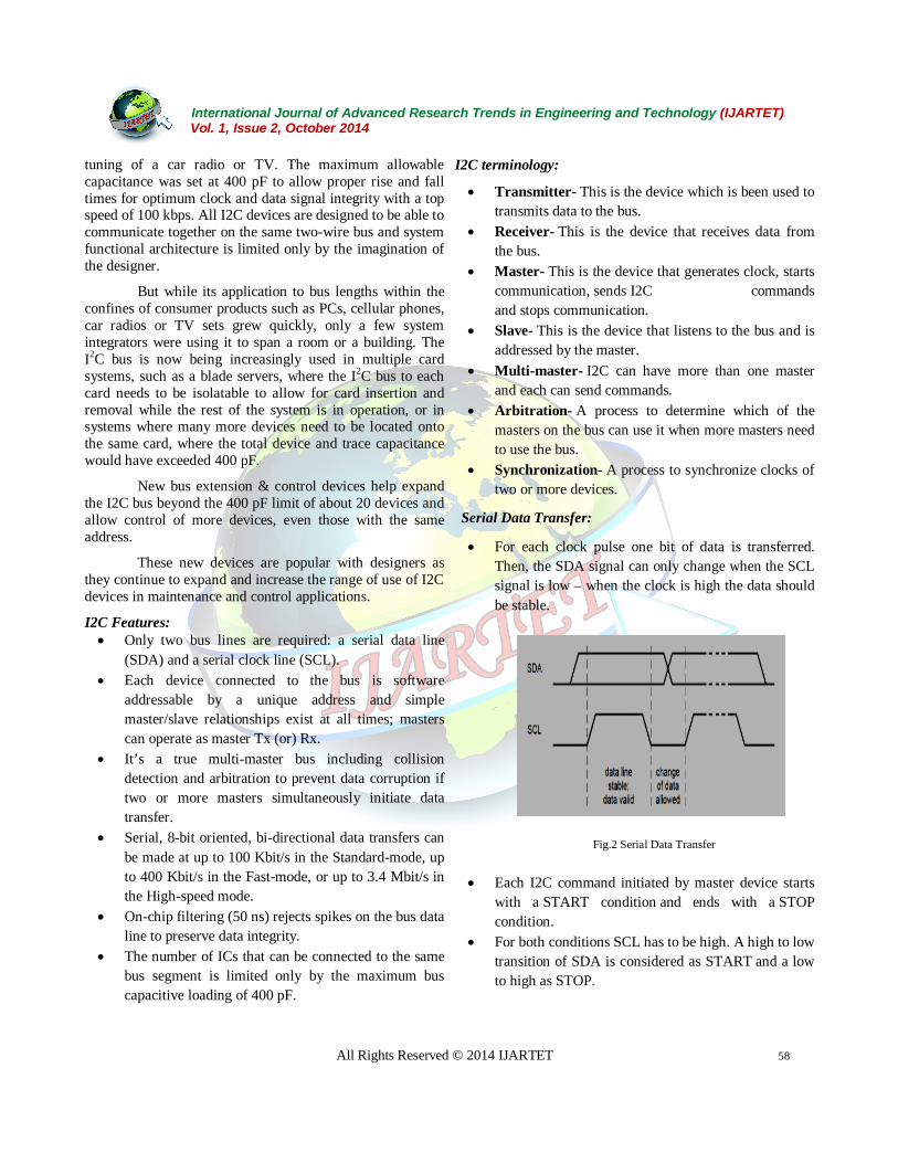
Serial Data Transfer:
For each clock pulse one bit of data is transferred. Then, the SDA signal can only change when the SCL signal is low – when the clock is high the data should be stable.
Fig.2 Serial Data Transfer
Each I2C command initiated by master device starts with a START condition and ends with a STOP condition.
For both conditions SCL has to be high. A high to low transition of SDA is considered as START and a low to high as STOP.

International Journal of Advanced Research Trends in Engineering and Technology (IJARTET) Vol. 1, Issue 2, October 2014
All Rights Reserved © 2014 IJARTET 59
I2C is a synchronous protocol, and hence, SCL is used to synchronize all the devices and the data transfer together.
Fig. 3 Start and Stop Conditions
After the Start condition the bus is considered as busy and can be used by another master only after a Stop condition is detected. After the Start condition the master can generate a repeated Start. This is equivalent to a normal Start and is usually followed by the slave I2C address. Microcontrollers that have dedicated I2C hardware can easily detect bus changes and behave also as I2C slave devices. However, if the I2C communication is implemented in software, the bus signals must be sampled at least two times per clock cycle in order to detect necessary changes.
I2C Data Transfer:
Fig4: I2C Data Transfer
Data on the I2C bus is transferred in 8-bit packets (bytes). There is no limitation on the number of bytes, however, each byte must be followed by an Acknowledge bit. This bit signals whether the device is ready to proceed with the next byte. For all data bits including the
Acknowledge bit, the master must generate clock pulses. If the slave device does not acknowledge transfer this means that there is no more data or the device is not ready for the transfer yet. The master device must either generate Stop or Repeated Start condition.
Fig.5 Data Output Transfer
Synchronization: Each master must generate its own clock signal and the data can change only when the clock is low. For successful bus arbitration a synchronized clock is needed. Once a master pulls the clock low it stays low until all masters put the clock into high state. Similarly, the clock is in the high state until the first master pulls it low. This way by observing the SCL signal, master devices can synchronize their clocks.
Arbitration:
For normal data transfer on the I2C bus only one master can be active. If for some reason two masters initiate I2C command at the same time, the arbitration procedure determines which master wins and can continue with the command. Arbitration is performed on the SDA signal while the SCL signal is high.
Each master checks if the SDA signal on the bus corresponds to the generated SDA signal. If the SDA signal on the bus is low but it should be high, then this master has lost arbitration. Master I2C device that has lost arbitration can generate SCL pulses until the byte ends and must then release the bus and go into slave mode. The arbitration procedure can continue until all the data is transferred. This means that in multi-master system each I2C master must monitor the I2C bus for collisions and act accordingly. Clock Synchronization and Handshaking:
Slave devices that need some time to process received byte or are not ready yet to send the next byte can pull the clock low to signal to the master that it should wait. Once the clock is released the master can proceed with the next byte.
International Journal of Advanced Research Trends in Engineering and Technology (IJARTET) Vol. 1, Issue 2, October 2014
All Rights Reserved © 2014 IJARTET 60
I2C Bus Transaction:
Alright, now that we are familiar with the I2C bus interface, let’s look into how the data transfer actually takes place through that interface. I2C supports unidirectional as well as bidirectional data transfer as mentioned below.
Acknowledge Scheme:
As mentioned earlier, I2C transfers 8 bits (1 byte) of data at a time. After the transfer of each byte is complete, the receiver must acknowledge it. To acknowledge, the receiver sends an ACK bit back to the transmitter.
The transmitter is the one, (could be either Master or Slave) transmits 1 byte of data (MSB first) to the receiver during 8 clock pulses of SCL, after which it releases the SDA line i.e. the SDA line becomes HIGH for the ACK clock pulse.
The receiver which is the one which (could be either Master or Slave, it depends) is obliged to generate an acknowledge after each byte sent by the transmitter by pulling the SDA line LOW for the ACK clock pulse (9th clock pulse) of SCL.
So overall, there are 9 SCL clock pulses required to transmit a byte of data. This is shown in the diagram below with the assumption that Masteries’ the transmitter. Case 1: Slave is at the receiver’s end Even in this case, there are two possible cases:
Case 1a:
The Slave-receiver which does not acknowledge the Slave address. In that case, it simply leaves the SDA line HIGH. Now the Master-transmitter either generates a Stop sequence or attempts a repeated Start sequence.
Case1b:
The Slave-receiver acknowledges only the Slave address, but after some time it is unable to receive any data and leaves the SDA line HIGH during the ACK pulse. Even in this case, usage of the Master-transmitter does the same – either generate a Stop sequence, or attempt a repeated Start sequence.
Case 2: Master is at the receiver’s end
Case 2a:
In this case, the Master is the one generating ACK, as well as responsible for generating Start/Stop sequence. This carries over for the data transmission.
Case 2b:
In this case, in order to signal the Slave-transmitter the end of data, the Master-receiver does NOT generate any ACK on the last byte clocked out of the Slave-transmitter.
In this case, the Slave-transmitter must let go of the SDA line to allow the Master to generate a Stop condition.
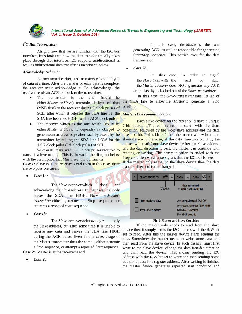
Master slave communication:
Each slave device on the bus should have a unique 7-bit address. The communication starts with the Start condition, followed by the 7-bit slave address and the data direction bit. If this bit is 0 then the master will write to the slave device. Otherwise, if the data direction bit is 1, the master will read from slave device. After the slave address and the data direction is sent, the master can continue with reading or writing. The communication is ended with the Stop condition which also signals that the I2C bus is free. If the master only writes to the slave device then the data transfer direction is not changed.
Fig. 5 Master and Slave Condition If the master only needs to read from the slave
device then it simply sends the I2C address with the R/W bit set to read. After this the master device starts reading the data. Sometimes the master needs to write some data and then read from the slave device. In such cases it must first write to the slave device, change the data transfer direction and then read the device. This means sending the I2C address with the R/W bit set to write and then sending some additional data like register address. After writing is finished the master device generates repeated start condition and
International Journal of Advanced Research Trends in Engineering and Technology (IJARTET) Vol. 1, Issue 2, October 2014
All Rights Reserved © 2014 IJARTET 61
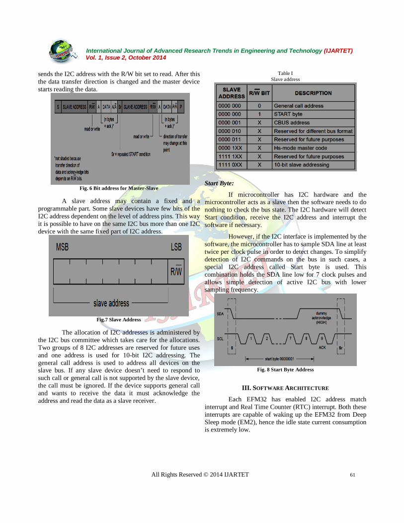
sends the I2C address with the R/W bit set to read. After this the data transfer direction is changed and the master device starts reading the data.
Fig. 6 Bit address for Master-Slave
A slave address may contain a fixed and a
programmable part. Some slave devices have few bits of the I2C address dependent on the level of address pins. This way it is possible to have on the same I2C bus more than one I2C device with the same fixed part of I2C address.
Fig.7 Slave Address
The allocation of I2C addresses is administered by
the I2C bus committee which takes care for the allocations. Two groups of 8 I2C addresses are reserved for future uses and one address is used for 10-bit I2C addressing. The general call address is used to address all devices on the slave bus. If any slave device doesn’t need to respond to such call or general call is not supported by the slave device, the call must be ignored. If the device supports general call and wants to receive the data it must acknowledge the address and read the data as a slave receiver.
Table I Slave address
Start Byte:
If microcontroller has I2C hardware and the microcontroller acts as a slave then the software needs to do nothing to check the bus state. The I2C hardware will detect Start condition, receive the I2C address and interrupt the software if necessary.
However, if the I2C interface is implemented by the software, the microcontroller has to sample SDA line at least twice per clock pulse in order to detect changes. To simplify detection of I2C commands on the bus in such cases, a special I2C address called Start byte is used. This combination holds the SDA line low for 7 clock pulses and allows simple detection of active I2C bus with lower sampling frequency.
Fig. 8 Start Byte Address
III. SOFTWARE ARCHITECTURE
Each EFM32 has enabled I2C address match interrupt and Real Time Counter (RTC) interrupt. Both these interrupts are capable of waking up the EFM32 from Deep Sleep mode (EM2), hence the idle state current consumption is extremely low.

International Journal of Advanced Research Trends in Engineering and Technology (IJARTET) Vol. 1, Issue 2, October 2014
All Rights Reserved © 2014 IJARTET 62
Fig. 9 Software Architecture of I2C
The I2C is continuously monitoring the I2C line. If a start condition followed by the I2Cs defined address, an address match interrupt is issued and data is received until a stop condition is detected. The Real Time Counter (RTC) is set to wake up the EFM32 regularly. If a reception is not in progress at the time of wake-up, a master transmission is initiated. The address match interrupt is disabled during the transmission and re-enabled afterwards.
IV. CONCLUSION With the heights of the technology autonomous car is no more a myth. It’s a reality! We would like to present that there must be further developments in this technology to make autonomous car more common all over the world. This can be happened by making the autonomous easy to operate for the user and the designers should concentrate more in producing autonomous cars, which should not cost a lot, they should in the vicinity of customers’ budget. With this type of vehicles there will be great advantages in the coming feature. Due to I2C technique, accident free driving is possible and fuel savage is also made possible by the technique, which will make the car to travel through shortest path. In the near future, autonomous car become more common all over the world. Indian efforts in the embedded technology can assure that these autonomous cars will become cheaper and may evolve with many more
advantages. So that we could find ourselves using these autonomous cars in the near feature.
ACKNOWLEDGEMENT
The authors would have like to thank the reviewers for their useful and constructive comments.
REFERENCES [1]. Arvind Sahu, Ravi Shankar Mishra, Puran Gour, “Design and
Interfacing of High speed model of FPGAS using I2C” IEEE 2010.
[2]. Shoaib.Shah Sobhan, Sudipta. Das and Iqbalur.Rahman, “Implementation of I2C using System Verilog and FPGA”, ICAEPE’2011.
[3]. P.Venkateswaran, A. Saynal, S. Das, S.K Proc. Research in Computing Science: Special Issues – Advances in Computer Science &Eng., ISSN 1870 – 406, pub .National Polytechnic Institute, Mexico, Vol.23, pp 191 -198 , Nov. 21-24,2006.
[4]. Xavier Righetti Xavier Righetti “Proposition of a Modular I2C-Based Wearable Architecture”IEEE-2010.
[5]. Jan O. Borchers, Wolfgang Samminger, Max M¨uhlh¨auser “Personal Orchestra: Conducting Audio/Video Music Recordings” IEEE-2009.
[6]. A.R.M. Khan, A.P.Thakare, S.M.Gulhane “FPGA-Based Design of Controller for Sound Fetching from Codec Using Altera DE2 Board” International Journal of Scientific & Engineering Research.
[7]. A.K. Oudjida, M.L. Berrandjia, R. Tiar, A. Liacha, K.Tahraou „FPGA Implementation of I2C & SPI Protocols”a Comparative Study IEEE 2009.
[8]. J.M .Irazabel & S.Blozis, Philips Semiconductors, “I2CManual, Application Note, ref. AN10216-0” March 24, 2012.
[9]. F. Leens, “An Introduction to I2C and SPI Protocols,” IEEE Instrumentation & Measurement Magazine, pp. 8-13, February 2009.
[10]. L. Bacciarelli et al, “Design, Testing and Prototyping of a Software Programmable I2C/SPI IP on AMBA Bus,” Conference on Ph.D. Research in Microelectronics and Electronics (PRIME'2006), pp. 373-376, ISBN: 1-4244-0157-7, Ortanto, Italy, June 2006.