
Implementing NTP - Cisco
6
Implementing NTP Network Time Protocol (NTP) is a protocol designed to time-synchronize devices within a network. Cisco IOS XR software implements NTPv4. NTPv4 retains backwards compatibility with the older versions of NTP, including NTPv3 and NTPv2 but excluding NTPv1, which has been discontinued due to security vulnerabilities. • Information About Implementing NTP, on page 1 • Configuring NTP, on page 2 Information About Implementing NTP NTP synchronizes timekeeping among a set of distributed time servers and clients. This synchronization allows events to be correlated when system logs are created and other time-specific events occur. NTP uses the User Datagram Protocol (UDP) as its transport protocol. All NTP communication uses Coordinated Universal Time (UTC). An NTP network usually receives its time from an authoritative time source, such as a radio clock or an atomic clock attached to a time server. NTP distributes this time across the network. NTP is extremely efficient; no more than one packet per minute is necessary to synchronize two machines to within a millisecond of each other. NTP uses the concept of a “stratum” to describe how many NTP “hops” away a machine is from an authoritative time source. A “stratum 1” time server typically has an authoritative time source (such as a radio or atomic clock, or a GPS time source) directly attached, a “stratum 2” time server receives its time via NTP from a “stratum 1” time server, and so on. NTP avoids synchronizing to a machine whose time may not be accurate, in two ways. First, NTP never synchronizes to a machine that is not synchronized itself. Second, NTP compares the time reported by several machines and does not synchronize to a machine whose time is significantly different than the others, even if its stratum is lower. This strategy effectively builds a self-organizing tree of NTP servers. The Cisco implementation of NTP does not support stratum 1 service; in other words, it is not possible to connect to a radio or atomic clock (for some specific platforms, however, you can connect a GPS time-source device). We recommend that time service for your network be derived from the public NTP servers available in the IP Internet. If the network is isolated from the Internet, the Cisco implementation of NTP allows a machine to be configured so that it acts as though it is synchronized via NTP, when in fact it has determined the time using other means. Other machines can then synchronize to that machine via NTP. Several manufacturers include NTP software for their host systems, and a publicly available version for systems running UNIX and its various derivatives is also available. This software also allows UNIX-derivative Implementing NTP 1
-
Upload
khangminh22 -
Category
Documents
-
view
4 -
download
0
Transcript of Implementing NTP - Cisco

Implementing NTP
Network Time Protocol (NTP) is a protocol designed to time-synchronize devices within a network. CiscoIOSXR software implements NTPv4. NTPv4 retains backwards compatibility with the older versions of NTP,includingNTPv3 andNTPv2 but excludingNTPv1, which has been discontinued due to security vulnerabilities.
• Information About Implementing NTP, on page 1• Configuring NTP, on page 2
Information About Implementing NTPNTP synchronizes timekeeping among a set of distributed time servers and clients. This synchronizationallows events to be correlated when system logs are created and other time-specific events occur.
NTP uses the User Datagram Protocol (UDP) as its transport protocol. All NTP communication usesCoordinated Universal Time (UTC). An NTP network usually receives its time from an authoritative timesource, such as a radio clock or an atomic clock attached to a time server. NTP distributes this time acrossthe network. NTP is extremely efficient; no more than one packet per minute is necessary to synchronize twomachines to within a millisecond of each other.
NTP uses the concept of a “stratum” to describe howmanyNTP “hops” away amachine is from an authoritativetime source. A “stratum 1” time server typically has an authoritative time source (such as a radio or atomicclock, or a GPS time source) directly attached, a “stratum 2” time server receives its time via NTP from a“stratum 1” time server, and so on.
NTP avoids synchronizing to a machine whose time may not be accurate, in two ways. First, NTP neversynchronizes to a machine that is not synchronized itself. Second, NTP compares the time reported by severalmachines and does not synchronize to a machine whose time is significantly different than the others, evenif its stratum is lower. This strategy effectively builds a self-organizing tree of NTP servers.
The Cisco implementation of NTP does not support stratum 1 service; in other words, it is not possible toconnect to a radio or atomic clock (for some specific platforms, however, you can connect a GPS time-sourcedevice). We recommend that time service for your network be derived from the public NTP servers availablein the IP Internet.
If the network is isolated from the Internet, the Cisco implementation of NTP allows amachine to be configuredso that it acts as though it is synchronized via NTP, when in fact it has determined the time using other means.Other machines can then synchronize to that machine via NTP.
Several manufacturers include NTP software for their host systems, and a publicly available version forsystems running UNIX and its various derivatives is also available. This software also allows UNIX-derivative
Implementing NTP1

servers to acquire the time directly from an atomic clock, which would subsequently propagate time informationalong to Cisco routers.
The communications betweenmachines running NTP (known as associations) are usually statically configured;each machine is given the IP address of all machines with which it should form associations. Accuratetimekeeping is made possible by exchanging NTPmessages between each pair of machines with an association.
The Cisco implementation of NTP supports twoways that a networking device can obtain NTP time informationon a network:
• By polling host servers
• By listening to NTP broadcasts
In a LAN environment, NTP can be configured to use IP broadcast messages. As compared to polling, IPbroadcast messages reduce configuration complexity, because each machine can simply be configured to sendor receive broadcast or multicast messages. However, the accuracy of timekeeping is marginally reducedbecause the information flow is one-way only.
An NTP broadcast client listens for broadcast messages sent by an NTP broadcast server at a designated IPv4address. The client synchronizes the local clock using the first received broadcast message.
The time kept on a machine is a critical resource, so we strongly recommend that you use the security featuresof NTP to avoid the accidental or malicious setting of incorrect time. Twomechanisms are available: an accesslist-based restriction scheme and an encrypted authentication mechanism.
When multiple sources of time (VINES, hardware clock, manual configuration) are available, NTP is alwaysconsidered to be more authoritative. NTP time overrides the time set by any other method.
Configuring NTP
Configuring Poll-Based AssociationsThe following example shows an NTP configuration in which the router’s system clock is configured to forma peer association with the time server host at IP address 192.168.22.33, and to allow the system clock to besynchronized by time server hosts at IP address 10.0.2.1 and 172.19.69.1:ntpserver 10.0.2.1 minpoll 5 maxpoll 7peer 192.168.22.33server 172.19.69.1
Configuring Broadcast-Based AssociationsThe following example shows an NTP client configuration in which interface 0/2/0/0 is configured to receiveNTP broadcast packets, and the estimated round-trip delay between an NTP client and an NTP broadcastserver is set to 2 microseconds:ntpinterface tengige 0/2/0/0broadcast clientexit
broadcastdelay 2
Implementing NTP2
Implementing NTPConfiguring NTP
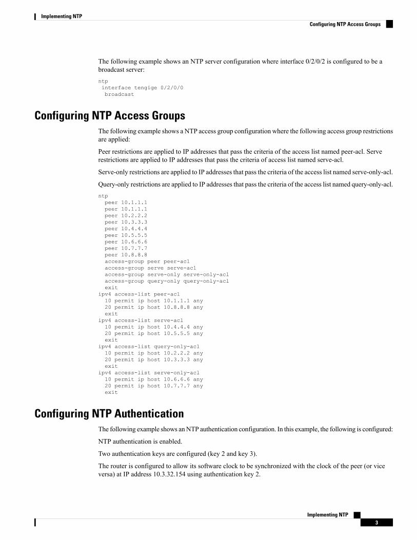
The following example shows an NTP server configuration where interface 0/2/0/2 is configured to be abroadcast server:ntpinterface tengige 0/2/0/0broadcast
Configuring NTP Access GroupsThe following example shows a NTP access group configuration where the following access group restrictionsare applied:
Peer restrictions are applied to IP addresses that pass the criteria of the access list named peer-acl. Serverestrictions are applied to IP addresses that pass the criteria of access list named serve-acl.
Serve-only restrictions are applied to IP addresses that pass the criteria of the access list named serve-only-acl.
Query-only restrictions are applied to IP addresses that pass the criteria of the access list named query-only-acl.ntppeer 10.1.1.1peer 10.1.1.1peer 10.2.2.2peer 10.3.3.3peer 10.4.4.4peer 10.5.5.5peer 10.6.6.6peer 10.7.7.7peer 10.8.8.8access-group peer peer-aclaccess-group serve serve-aclaccess-group serve-only serve-only-aclaccess-group query-only query-only-aclexit
ipv4 access-list peer-acl10 permit ip host 10.1.1.1 any20 permit ip host 10.8.8.8 anyexit
ipv4 access-list serve-acl10 permit ip host 10.4.4.4 any20 permit ip host 10.5.5.5 anyexit
ipv4 access-list query-only-acl10 permit ip host 10.2.2.2 any20 permit ip host 10.3.3.3 anyexit
ipv4 access-list serve-only-acl10 permit ip host 10.6.6.6 any20 permit ip host 10.7.7.7 anyexit
Configuring NTP AuthenticationThe following example shows anNTP authentication configuration. In this example, the following is configured:
NTP authentication is enabled.
Two authentication keys are configured (key 2 and key 3).
The router is configured to allow its software clock to be synchronized with the clock of the peer (or viceversa) at IP address 10.3.32.154 using authentication key 2.
Implementing NTP3
Implementing NTPConfiguring NTP Access Groups

The router is configured to allow its software clock to be synchronized with the clock by the device at IPaddress 10.32.154.145 using authentication key 3.
The router is configured to synchronize only to systems providing authentication key 3 in their NTP packets.ntpauthenticateauthentication-key 2 md5 encrypted 06120A2D40031D1008124authentication-key 3 md5 encrypted 1311121E074110232621trusted-key 3server 10.3.32.154 key 3peer 10.32.154.145 key 2
Disabling NTP on an InterfaceThe following example shows an NTP configuration in which 0/2/0/0 interface is disabled:
ntpinterface tengige 0/2/0/0disableexit
authentication-key 2 md5 encrypted 06120A2D40031D1008124authentication-key 3 md5 encrypted 1311121E074110232621authenticatetrusted-key 3server 10.3.32.154 key 3peer 10.32.154.145 key 2
Configuring the System as an Authoritative NTP ServerThe following example shows a NTP configuration in which the router is configured to use its own NTPserver clock to synchronize with peers when an external NTP source becomes unavailable:ntpmaster 6
Updating the Hardware ClockThe following example shows an NTP configuration in which the router is configured to update its hardwareclock from the software clock at periodic intervals:ntpserver 10.3.32.154update-calendar
Configuring NTP Server Inside VRF Interface
No specific command enables NTP; the first NTP configuration command that you issue enables NTP.Note
RP/0/RP0/CPU0:router# configureRP/0/RP0/CPU0:router(config)# ntpRP/0/RP0/CPU0:router(config)# ntp vrf Customer_ARP/0/RP0/CPU0:router(config)# ntp vrf Customer_A source bvi 70RP/0/RP0/CPU0:router(config-ntp)# end
Implementing NTP4
Implementing NTPDisabling NTP on an Interface

orRP/0/RP0/CPU0:router(config-ntp)# commit
Implementing NTP5
Implementing NTPConfiguring NTP Server Inside VRF Interface

Implementing NTP6
Implementing NTPConfiguring NTP Server Inside VRF Interface