Hole detection, gripping and I2C communication of a climbing ...
48
University of Maribor Faculty of Electrical Engineering and Computer Science Public University of Navarre School of Industrial Engineers and Telecommunications HOLE DETECTION, GRIPPING AND I2C COMMUNICATION OF A CLIMBING ROBOT DIPLOMA WORK STUDENT: CARLOS JUAN DE DIOS URSÚA STUDY PROGRAM: ELECTRICAL AND ELECTRONIC ENGINEERING MENTOR: SUZANA URAN Maribor, July 2016
-
Upload
khangminh22 -
Category
Documents
-
view
0 -
download
0
Transcript of Hole detection, gripping and I2C communication of a climbing ...

University of Maribor
Faculty of Electrical Engineering and Computer Science
Public University of Navarre
School of Industrial Engineers and Telecommunications
HOLE DETECTION, GRIPPING AND I2C COMMUNICATION
OF A CLIMBING ROBOT
DIPLOMA WORK
STUDENT: CARLOS JUAN DE DIOS URSÚA
STUDY PROGRAM: ELECTRICAL AND ELECTRONIC ENGINEERING
MENTOR: SUZANA URAN
Maribor, July 2016

Hole detection, gripping and I2C communication of a climbing robot Carlos Juan de Dios Ursúa
1
INDEX 1.- INTRODUCTION ........................................................................................................................................ 2
2.- MICROCHIP............................................................................................................................................... 4
2.1.- OPTIONS AND CHOICE ...................................................................................................................... 4
2.1.1.- dsPIC33FJ64MC802 .................................................................................................................... 4
2.1.2.- PIC18F25K22 .............................................................................................................................. 4
2.1.3.- Choice ......................................................................................................................................... 5
2.2.- THE CHOSEN PIC. PIC18F25K22 ........................................................................................................ 6
3.- HOLE DETECTION ..................................................................................................................................... 9
3.1.- SHARP SENSOR GP2Y0A21YK0F ........................................................................................................ 9
3.2.- PROCESS AND PROBLEMS FOUND .................................................................................................. 10
3.3.- HOLE DETECTION PROGRAM .......................................................................................................... 16
3.4.- GRIPPER INCLINATION PROGRAM .................................................................................................. 18
4.- GRIPPER .................................................................................................................................................. 20
5.- COMUNICATION BETWEEN PICS ............................................................................................................ 24
5.1.- OBJECTIVE AND SELECTION ............................................................................................................ 24
5.2.- I2C PROTOCOL ................................................................................................................................. 24
5.3.- PROGRAMMING I2C ........................................................................................................................ 26
6.- FINAL PROGRAM .................................................................................................................................... 31
7.- OTHER USEFUL PROGRAMS ................................................................................................................... 42
7.1.- COORDINATES OF ANY POINT ......................................................................................................... 42
7.2.- DIAMETER OF A CIRCLE ................................................................................................................... 43
8.- CONCLUSION .......................................................................................................................................... 45
8.1.- FUTURE DEVELOPMENTS ................................................................................................................ 45
9.- REFERENCES ........................................................................................................................................... 47

Hole detection, gripping and I2C communication of a climbing robot Carlos Juan de Dios Ursúa
2
1.- INTRODUCTION Throughout history, bridges have been one of the most important structures and they are still
nowadays, to cross rivers, roads or even whole valleys. In the past, the materials most used to build them
were wood and stone, but nowadays almost all of them are built in iron or concrete. The iron has been
used since the last years of the XVIII century and one hundred years later, approximately, appeared the
first concrete bridges.
The iron structures are durable and really strong and resistant, but their maintenance cost is high
and is necessary to protect them against the fire because, although they can be incombustible, they are
really good heat conductors. On the other hand, the concrete bridges are also durable, with high
resistance to the compression, bending and tractive forces and, as a difference, to the fire too and they
require low maintenance. However, some inspections are needed, for example, to detect some cracks on
it. With the objective to climb the legs of the concrete bridges and inspect them to find those cracks or
any problem on them, the University of Maribor is developing a Climbing Robot, of which this project
takes part in.
The Črni Kal viaduct, which can be seen in the first picture of the Image 0, was the main objective
when the idea of the robot climbing came. To climb the legs of the bridges, the robot has been designed
to grip on the small holes that reinforced concrete blocks have on their sides and in the second picture of
the Image 0 can be seen the holes in the leg of a bridge.
Image 0. Crni kal viaduct [9] and holes in the leg of a bridge
The small part of the whole structure that the robot has to grip on the wall is going to be called
gripper in the report. The robot has been designed to have two arms and three grippers, two of them at
the end of the arms and the other one in the middle. It will move the arms along the wall until they detect
a hole and, then, they will grip on it. A photo of the structure of the robot can be seen in the Image 1.

Hole detection, gripping and I2C communication of a climbing robot Carlos Juan de Dios Ursúa
3
Image 1. Climbing Robot
This project will consist in programming a part of the entire climbing robot programming. In the
Image 2 is shown a scheme of the different programs that the robot is going to have. First of all, the gripper
program is the one that is going to be develop in this project, then, there will be also needed a program
for controlling the servos, another one to control the central microchip, which will be the I2C master and,
finally, one extern program for a Raspberry Pi to communicate with the central microchip using Bluetooth.
Image 2. Scheme of robot communication
The aims of this project, as a part of the robot climbing to program the gripper, are mainly three.
The first is detecting the holes on the wall with a distance sensor, the second one, controlling the motor
that lets the robot grip on the wall and the third one communicate the pic with other pics of the robot
using I2C protocol.
The gripper, which is the final element of the robot, is in which the sensors and the mechanism
to grip are held and, as consequence, is the only structure that has been used to develop this project.
For this project, have been needed two sharp sensors GP2Y0A21YK0F, the gripper, and a printed
board with the microchip. After this little introduction to have an idea of how the project is organized and
its objectives, the different parts of the project will be carefully explained.

Hole detection, gripping and I2C communication of a climbing robot Carlos Juan de Dios Ursúa
4
2.- MICROCHIP The microchip is the brain of this project execution. It must be programmed to control every input
and output necessary to ensure that the robot behaves in the correct way. It must receive the value from
the sensors, analyze them, move the gripper to grip when necessary and send the appropriate data to
other part of the robot in the right moment. That is why the microchip is a really important part of the
project and the choice of it must be made carefully.
2.1.- OPTIONS AND CHOICE There are a lot of different microchips, so the choice can be a really laborious task. Fortunately,
the university offered two microchips that they had and they are used to, so they could be studied to
choose the best one for the purpose or, at least, discard them but with a clear idea of the characteristics
that the chosen pic must have.
2.1.1.- dsPIC33FJ64MC802 The characteristics of the first microchip, the dsPIC33FJ64MC802, can be seen on the microchip
webpage, where can be found a table with all the data. In the Image 3, the table with the data about the
dsPIC33FJ64MC802 is shown.
Image 3. dsPIC33FJ64MC802 [2]
Looking at the characteristics of the dsPIC33FJ64MC802 and taking into account the needs for
this project, the analysis about this microchip can be done. First of all, the size of the microchip is an
important factor to consider, to avoid buying a microchip much bigger or smaller than needed. Knowing
that, initially, there will be needed six pins, two for the sensors, two for the motor and two for the I2C
communication, so this pic with 28 pins is oversized for this purpose. Moreover, for the programs that will
be used, the RAM is also excessive.
Apart from that initial impression, there are some characteristics that the pic should have. First of
them, for the sensors, it will be necessary two analog channels, for the communication one I2C port and
for the gripper it would be advisable to use two pwm ports. Additionally, one UART would be
recommendable to send data to visualize on the computer and, also, few timers. As can be seen, the
microchip contains all of these requirements, with six analog channels, twelve pwm outputs, one I2C port,
two UART and seven timers. In conclusion, this microchip can be used for this project but is a bit excessive
for the purpose needed.
2.1.2.- PIC18F25K22 The other option is the PIC18F25K22, which characteristics are shown in the table of the website
that can be seen in the Image 4.

Hole detection, gripping and I2C communication of a climbing robot Carlos Juan de Dios Ursúa
5
Image 4. PIC18F25K22 [3]
This microchip has less RAM, but enough for this project, and also 28 pins. About the specified
necessities, this microchip has seventeen analog channels, two I2C ports, two UART and seven timers, and
five CCP modules, which can be configured to use the pwm. Finally, one advantage of using this microchip
is that in the university there is a printed board with a circuit prepared for this microchip. This board
connects the microchip with some elements that facilitate the task to connect inputs, outputs, source
voltage and ground, and the programming wires.
2.1.3.- Choice Comparing both microchip it is possible to find out that both are enough for the purpose, but the
first one is most expensive and, moreover, the second pic has a printed board already prepared to
program and work with it. So, as the second pic has the advantage of being simpler and more basic,
cheaper, and it has his own printed board, the second microchip was chosen.

Hole detection, gripping and I2C communication of a climbing robot Carlos Juan de Dios Ursúa
6
2.2.- THE CHOSEN PIC. PIC18F25K22 The PIC18F25K22 has been used for this project on a printed board to make easier its use and
connections. The schematics of the board, the drawing of the printed connections and the real board,
with the microchip in the middle, can be seen in the Image 5.

Hole detection, gripping and I2C communication of a climbing robot Carlos Juan de Dios Ursúa
7
Image 5. Schematics, drawing of printed connections and real Board with the PIC18F25K22
With the board of the Image 5 the programs were tested, but it is big to include the board in the
robot’s structure, so another board was designed with the same microchip. The new board smaller and
designed specifically for this purpose by Blaž Berden [8] can be seen in the Image 6, also with the drawing
of the printed connections. Anyway, the board exposed above was used as the master for the I2C
communication, because the board of the Image 6 is an I2C slave.
Current Sensor
H bridge
PIC
Motor connectors
I2C connectors
Sensors connectors

Hole detection, gripping and I2C communication of a climbing robot Carlos Juan de Dios Ursúa
8
Image 6. New schematic, drawing of printed connections and board
The characteristics of the microchip have been explained before, so now it won’t be repeated.
However, to program the pic and connect the different inputs and outputs in their respective pins, in the
Image 7 is shown a scheme of the pic with the characteristics of each pin that will be important for this
project.
LEGEND:
- MCLR: Master clear (external
reset)
- Vpp, Vdd, Vss: Voltage supply
- AN: Analog pins
- SOSCx, TxCKI, TxG: Timer
associated with pin
- CCP: Compare / capture / pwm
- SCLx: Clock pin I2C
- SDAx: Data pin I2C
- INTx, IOC: Interruption
- RXx, TXx: Programming
- PGC, PGD: Serial Programming
In the scheme only have been written the options of each pin that is needed in this project. On
the right column of the Image 7 is a little legend with the meaning of the different properties of each pin.
Image 7. PIC18F25K22

Hole detection, gripping and I2C communication of a climbing robot Carlos Juan de Dios Ursúa
9
3.- HOLE DETECTION The first objective of the project was detecting the holes on the wall with a distance sensor. The
program must detect when a hole is under each sensor and send the information whether there is a hole
or not to other microchips of the robot. The sensor used for this purpose is a laser distance sensor, Sharp
GP2Y0A21YK0F.
3.1.- SHARP SENSOR GP2Y0A21YK0F The Sharp sensor GP2Y0A21YK0F [10], which can be seen in the Image 8, is a laser distance sensor
that can find an object in a distance up to 80cm.
Image 8. Sharp sensor GP2Y0A21YK0F
This sensor has two diodes, the one on the left of the Image 8 is the transmitter and the one on
the right is the receiver. The first one sends the laser signal that is received by the second one after
reflecting in the object found. The sensor then calculates the distance of the object and sends a voltage
related to the distance, as it can be seen on the graphic shown in the Image 9.
Image 9. Voltage - Distance graphic of the sensor

Hole detection, gripping and I2C communication of a climbing robot Carlos Juan de Dios Ursúa
10
As the graphic shows, it has a maximum value slightly higher than 3V on objects at a distance of
6cm approximately, and a minimum value lower than 0.5V on objects nearer than 1cm and farer than
60cm. Once known how the sensor works and which is the voltage as a function of the distance, is time
to work with it and program the microchip to get the data.
3.2.- PROCESS AND PROBLEMS FOUND Despite the clarity of the objective and the simplicity of the issue as it is just detecting a hole with
the sensors, the process to get the expected results was hard and long as a consequence of the several
problems that appeared. First of all, having a look at the graphic of the Image 9, it can be seen that there
is an ambiguity because there are two possible distances for the same output in volts. For example, if the
sensor output is 2’5V, it is impossible to know whether the distance between the object and the sensor is
4 or 9 cm, and if the sensor output is 1V, the distance could be 2 or 28cm. To solve this ambiguity, the
sensors were located on the gripper with a distance higher than 5 cm to the floor, so that it is not possible
to be on the left side of the curve. The first gripper design to hold the sensors can be seen in the Image
10 and was designed with the enough height to avoid the problem recently explained.
Image 10. First Gripper with the sensors
To start with the procedure, the sensors were connected to the analog ports RA0 and RA1, as can
be seen in the Image 11, and the first program was done as a first contact with the program (mikroC), the
microchip and the sensors.
Image 11. Sensors connection

Hole detection, gripping and I2C communication of a climbing robot Carlos Juan de Dios Ursúa
11
The code of the first program is shown in the Image 12 and, then, it will be explained the general
purpose and way of procedure of the program, although in the comments are written almost every
indication needed to understand the program.
Image 12. Code of the first program commented

Hole detection, gripping and I2C communication of a climbing robot Carlos Juan de Dios Ursúa
12
This program waits until the user inserts a command from the UART window. When the user
inserts an ‘A’, the leds connected to the PORT B are switched on and when the user insets a ‘S’, they are
switched off. When the user inserts a ’D’, the program gets the value of the first sensor and prints it on
the screen and when a ‘F’ is inserted, the program gets the value of the second sensor and is printed on
the screen.
With this program, the basics of the program ‘MikroC’ were learnt as well as the UART
communication and the sensors were tested, obtaining different values when putting an object with
different distances. One example of the program working can be seen in the Image 13, where an object is
separated 20 cm from the sensors.
Image 13. Picture of UART example of Program 1
Now the sensors worked and it was possible to measure the distance with them, so it was time to
start with the objective to detect the holes. That is why the next program was done with this objective.
This program uses the ‘timer 2’ with interruptions to get the value from the sensors each same time, it
prints them on the screen and inserts them into two arrays, one for each sensor. In the Image 14 is the
program commented.

Hole detection, gripping and I2C communication of a climbing robot Carlos Juan de Dios Ursúa
13

Hole detection, gripping and I2C communication of a climbing robot Carlos Juan de Dios Ursúa
14
Image 14. Program for getting sensor values
This program waits 1ms, then, it is interrupted, and the value of the sensors are saved into the
arrays s1 and s2 respectively. When the arrays are full, the program stops. If the size of the arrays is 100,
the program will take 100 values of each sensor, one every 1ms, so it will finish in 100ms. Then, it is
possible to look at the values and see whether a hole was detected or not. However, for testing, the value
of count of the ‘if’ in the line 111 is written bigger so that is possible to see the values of the sensors at
the same time that they measure. For example, if the value were 1000, the sensor would measure each 1
second, what would let the user read the value and move the sensors to read a new value the next second.
To set the Timer 2 so that it interrupts with every 1ms, is necessary to calculate the value of PR2,
according to the next equation:
𝑇𝑖𝑚𝑒 = 𝑃𝑟𝑒𝑑𝑖𝑣𝑖𝑠𝑜𝑟 ∗ 𝑃𝑜𝑠𝑡𝑑𝑖𝑣𝑖𝑠𝑜𝑟 ∗ (𝑃𝑅 + 1) ∗4
𝐹𝑜𝑠𝑐
Having defined the pre-divisor and the post-divisor as 16 both of them, and with the frequency of
the oscillator equal to 32MHz, the value of PR is calculated:
1 ∗ 10−3 = 16 ∗ 16 ∗ (𝑃𝑅 + 1) ∗4
32 ∗ 106 →
𝑃𝑅 =1 ∗ 10−3
16 ∗ 16∗
32 ∗ 106
4− 1 = 30.25 → 𝑃𝑅 = 30
With this program it was possible to test if the hole detection was correct. It was done by trying
to measure different holes in several ways and seen how the detection was. As it has been said before, to
do that, in the line 111 of the program the value was set to 1.000 to have time enough to move the gripper
with the sensors and look at the value before moving again. While testing, two main problems appeared.
The first problem came out when small holes were about to be measured. It could be seen that
there were difficulties to detect little holes, so several different hole sizes were tested to detect where
was the limit. This test showed that the holes should have, at least, 1cm of diameter. The second problem
appeared because the holes were not detected depending on the position of the sensor above them,
concretely, when the hole was under the half part of the sensor where the receptor is, it was not detected
and when it was under the transmitter, it detected without problems.

Hole detection, gripping and I2C communication of a climbing robot Carlos Juan de Dios Ursúa
15
Once the solution of the problems was found and the program was able to detect the holes, the
gripper structure was changed so that it could contain the sensors, the motor and could be fixed on the
robot structure. The new gripper, that can be seen in the Image 15, is longer and, as consequence, the
sensors are farer from the surface.
Image 15. New Gripper
When the new gripper was tested it was found that there were errors in the measurements, and
it was not possible to guess when the gripper was above a hole looking at the values of the sensors. The
first hypothesis was that, as the space between the end of the gripper and the sensor is very long and
narrow, the sensors might be detecting the walls. Moreover, one sensor was removed from the gripper
and fixed out of it with the same distance from the end, and it detected without problems. To solve the
problem, the wall of one sensor was cut with one raw, and the new gripper can be seen in the second
picture of the Image 15 and in the Image 16.
Image 16. Gripper cut
After cutting the gripper, the results of the sensor measurements were still wrong, even,
sometimes, it was possible to appreciate when the sensors detected a hole, but instead of decreasing the
value with the distance, it increased, so the behavior of the sensor was unexpected and wrong. It

Hole detection, gripping and I2C communication of a climbing robot Carlos Juan de Dios Ursúa
16
demonstrated that the problem wasn’t solved by cutting the wall. Then, the second hypothesis arose. The
sensors weren’t well fixed on the gripper and they moved easily, so they were fixed with a tape adhesive
on both sides. Then, the sensors measured as expected and it was possible to detect when a hole was
under any sensor.
After all this process, the objective to detect the holes with the distance sensor was fulfilled, so
the next thing to do was a program that prepare to send the information, without mistakes, of the hole
presence or not under the sensors.
3.3.- HOLE DETECTION PROGRAM Using the program that gets the value of the sensors each millisecond, with this new program,
the data is adapted and prepared to send each 100 milliseconds if there is a hole under the sensors or
not. The central pic of the robot must know the information of the sensors updated each 100 ms to move
the robot in the correct way, so that is why this program is prepared. The program can be seen in the
Image 17 with comments and, then, it will be explained how it works.

Hole detection, gripping and I2C communication of a climbing robot Carlos Juan de Dios Ursúa
17
Image 17. Hole detection program

Hole detection, gripping and I2C communication of a climbing robot Carlos Juan de Dios Ursúa
18
This program will work as the previous one. It will take the values of the sensors each millisecond
but, in this case, the way of proceed with the data is different. First of all, it will be defined the variable
‘holeLimit’ that, according to tests done with the previous program, will be the number that separate the
values of a hole detection and the values of not detecting a hole, it means, if the value measured from
one sensor is lower than ‘holeLimit’, it has detected a hole, otherwise, not. Finally, it must be said that, as
the information must be sent each 100ms, the hole detection or not, will be a result of 100 measurements.
Each millisecond, the program gets the value from each sensor and if it is lower than ‘holeLimit’,
if it has detected a hole, the number ‘hole1’ (or ‘hole2’, depending on the sensor that has detected) is
increased. In case that the value from the sensor is higher, it means that it has not detected a hole, the
respective variable is decreased. After 100ms, the value of hole1 and hole2 are printed and their values
will be between 100 (all the time detected a hole) and -100 (didn’t detect a hole in any measurement).
Then, the process starts again.
Once this program is completed, the next necessity is to make sure that the gripper is aligned with
the wall, that it is not inclined.
3.4.- GRIPPER INCLINATION PROGRAM This program, as has been said, is necessary when the motor is going to grip on the wall to make
sure that it will get into the hole the more perpendicular way possible. It will be prepared so that each 2
seconds, the program checks if the gripper is aligned and print in the screen if the gripper is leveled, if the
sensor 1 is lower or if the sensor 2 is lower, depending on the inclination. The program commented can
be seen in the Image 18 and, then, it will be explained.

Hole detection, gripping and I2C communication of a climbing robot Carlos Juan de Dios Ursúa
19
Image 18. Gripper inclination program
First of all, the value s1Lim and s2Lim are, approximately, the values of each sensor when the
gripper is close to the wall and by comparing them is set the difference between the two sensors when
the gripper is leveled. This difference is the variable ‘dif1’, and is used to calculate the variable ‘differhole’,
that shows if the gripper is leveled or not. To calculate ‘differhole’, the value of each sensor is introduced
into valor1 and valor2, respectively, and are subtracted, subtracting also the value of ‘dif1’ as an offset to
compare the level. Then, with an if structure, which values can be changed to calibrate the system, is
deduced if the robot is leveled or not and, in this case, if the sensor 1 is lower or is the sensor 2.
3.5.- RESULTS After studying the hole detection of the sensors, the results obtained are going to be described
here. First of all, it has been seen that the sensors have high precision, it means that rarely detect a hole
when it isn’t and the other way around, rarely doesn’t detect a hole when it should. It allows reduce the
size of the arrays from 100 to reduce the time when the hole detection is refreshed from 100 ms. Another
result found was that the holes to be measured should have, at least, 1 cm of diameter and it didn’t matter
if the hole were a bit inclined.
The results from the inclination detection are that it also works pretty well and it can detect an
inclination in any direction.

Hole detection, gripping and I2C communication of a climbing robot Carlos Juan de Dios Ursúa
20
4.- GRIPPER The gripper, as has been explained before, is the final structure of the robot and can be seen in
the previous images 15 and 16. This structure contains the sensors and the motor that allows the robot
to grip on the wall. In this section, it will be explained the program developed to control the motor. This
motor was prepared by Tadej Peršak in his diploma work [1] and he prepared it so that when it has +5V
as input, the final part goes out and becomes bigger to grip on the holes and when it has -5V as input, the
final part does the opposite movement. The two extreme positions can be seen in the Image 19.
Image 19. Extreme position of the gripper
Now, it is prepared a program that moves the motor from one extreme position to the other.
Moreover, the current that goes into the motor is measured to stop if it gets really high. To know that the
motor has reached one extreme position, if the current increases drastically, then the motor is gripped on
a hole or already into the gripper. In the Image 20, it is shown the program commented that moves the
gripper in one direction until the current becomes high and, then, the other way around.

Hole detection, gripping and I2C communication of a climbing robot Carlos Juan de Dios Ursúa
21
Image 20. Gripper in and out program
This program interrupts every millisecond, gets the value from the current sensor in the
equivalent voltage value, and convert it into the current value. After 150 ms, the program makes the
average of the 150 previous measurements and print the value of the average current in the screen.
In the main program, knowing that every 150ms the value of the average current will be
refreshed, are checked four options. The first of them is that the current value is greater than 200mA and
the direction is 1 and, in this case, the direction is changed to 2. If the current is over 200mA but, in this
case, the direction is 2, the direction is changed to 1. In case that the current is lower than 200mA, the
motor continues in the same direction.

Hole detection, gripping and I2C communication of a climbing robot Carlos Juan de Dios Ursúa
22
This program has been used to calibrate the conversion of the output of the current sensor, to
determine the value of the current when the direction must be changed and see the behavior of the
motor, but in the real situation the motor will never be programmed to work as in this program is done.
To try the gripper in the way that will be used in the final program is written the program that can be seen
in the Image 21 and is based in the previous one.

Hole detection, gripping and I2C communication of a climbing robot Carlos Juan de Dios Ursúa
23
Image 21. Grip control program
In this program, as in the previous one, each millisecond is measured the value of the current and
every 150ms the average value of the current is obtained. The difference is in the main program. In this
case, the motor is stopped until a letter is sent from the keyboard to the UART port. If the letter is ‘A’, the
motor will move in one direction until the current increase because it has gripped in a hole or because the
grip is already inside of the gripper. The same happens when the letter ‘S’ is introduced, but in this case
the motor moves in the other direction. It is also possible to stop the program not only when it is gripped
or inside the gripper, but also when the letter ‘M’ is introduced.
With this program the gripper is controlled, so the next step of the project is communicating the
microchip of the gripper with the central microchip of the robot using the I2C protocol. This procedure
will be explained in the next section.

Hole detection, gripping and I2C communication of a climbing robot Carlos Juan de Dios Ursúa
24
5.- COMUNICATION BETWEEN PICS Throughout the whole project it has been worked with a microchip that will control every part of
the gripper, so it will be located there. However, the robot will have several different pics, each one
located near the part that controls and it will have a central microchip that communicates with the rest
and controls the movements of the robot. With this configuration, it is clear the necessity to use a protocol
of communication between each microchip and the central one. In this section is explained how this issue
was tackled.
5.1.- OBJECTIVE AND SELECTION There are several communication protocols that could have been used to communicate the
microchip, but it was chosen I2C because of the advantages that it presents for this situation. First of all,
the disadvantages of I2C protocol must be analyzed to make sure that there won’t be problems with it.
For instance, the I2C communication speed is quite low, about 100kb/s, but for this application is
not needed a really high communication speed, so it is more than enough. Other disadvantage of the I2C
protocol is that it is not advisable for long distances, but it is not a problem because every microchip will
be on the robot structure. Moreover, I2C communication is half-duplex instead of full-duplex, what does
not allow send and receive data at the same time but, as in the previous disadvantages, it is not a problem
because, for this application, the communication is not very exigent in that way. The last important
disadvantage of I2C protocol is that the number of slaves is not as high as in other protocols. Anyway, it
is enough for the number of slaves that the robot will have.
Once that the main disadvantages of I2C protocol are analyzed and has been seen that they are
not a problem for this application, the advantages are considered to see that it is the most advisable for
the climbing robot.
The first advantage, and really advisable for a structure with several joints and possible
movements, is that it only uses two wires, one to send the data and the other one the clock signal.
Moreover, if necessary, it is easy to add new slaves to the bus and it is possible to have more than one
master, just in case.
After considering the pros and cons of I2C protocol, it was finally chosen to communicate the
central microchip (master) with the rest of microchips (slaves).
5.2.- I2C PROTOCOL To understand the I2C protocol for programming is necessary to learn the basics of this protocol,
so a brief explanation is now given. First of all, I2C is designed as a master-slave bus. The data transfer is
always started by the master and the slave just react to the master requirements. There can be more than
one master and, in this case, to communicate between two masters, one of them will behave as a slave.
Anyway, in this project is only used one master, so that situation is irrelevant for this purpose.
To communicate with I2C, only two wires are needed, the clock signal and the data line. Both
wires need pull-up resistances and the connection scheme can be seen in the Image 22.

Hole detection, gripping and I2C communication of a climbing robot Carlos Juan de Dios Ursúa
25
Image 22. I2C connection scheme [4]
The data communication is serial, with address to slaves, and half-duplex. The half-duplex means
that is used the same wire to send and to receive data, so both actions cannot be done at the same time.
One clear example of a half-duplex system is the communication between humans, because when one is
talking the other one is listening and the other way around, but it is not possible to talk and listen at the
same time. By contrast, full-duplex systems use two different communication ways and they can send and
receive data at the same time. The difference between half-duplex and full-duplex can also be clearly seen
in the Image 23.
Image 23. Differences between half-duplex and full-duplex [5]
To start the communication between the master and one slave, the master send the starting
signal followed by one byte. The first seven bits of this byte are the address of the slave with which is
going to communicate, and the last bit tells the slave if the master is sending data or is going to receive it.
The ACK (acknowledge) is sent from the slave when writing and from the master when reading. The last
read byte is recognized by the master as a NACK (not acknowledge), to indicate the end of the
transmission.
While the line is empty, it means that nothing is been sent, the clock and the data signals are high.
When the master sends the starting signal, the clock signal starts and, then, the bits of the communication
data are changed when the clock signal is low, until the stop bit, that is sent when the clock signal is high.
This relation between the data sent and the clock signal is shown in the Image 24.
Image 24. Data and clock waves [6]

Hole detection, gripping and I2C communication of a climbing robot Carlos Juan de Dios Ursúa
26
5.3.- PROGRAMMING I2C To test the I2C communication between two pics, according to the information provide by
microchip [11], the program shown in the Images 25 and 27 was done. In this program when a number is
introduced form the UART port to the master, it is sent to the slave and each second reads data from the
slave. The slave will send every second to the master the same number that the master sent to the slave
the last time. The master code is shown in the Image 25.
Image 25. I2C communication - Master code

Hole detection, gripping and I2C communication of a climbing robot Carlos Juan de Dios Ursúa
27
For the master code is necessary to initialize the I2C port, and set the speed to 100kb/s. Then, in
the infinite loop, the program checks if any new number has been introduced from the keyboard. Only in
that case, the program will send the number introduced to the slave and wait for one second. Then, the
program will ask the slave to receive data from it and will wait for another second. Before going to send
or to receive data, the I2C communication must be started, the direction of the slave sent and, after
sending or receiving the data, stopped.
As can be seen in the program, when asking to send data, the address of the slave is different
than the address of it when asking to receive data. In this case, the address of the slave is 8, but when the
master was going to send data it wrote as address 16 (10 in hexadecimal) and when it was going to receive
data, it wrote as address 17 (11 in hexadecimal). The reason of it can be seen in the Image 26 and is that
the first 7 bits of the byte are the address of the slave and the last bit indicate if it is going to send or
receive data.
SENDING DATA FROM MASTER: RECEIVING DATA FROM MASTER
ADDRESS BYTE:
0 0 0 1 0 0 0 0 = 16
Address = 8 Sending (bit = 0)
0 0 0 1 0 0 0 1 = 17
Address = 8 Receiving (bit = 1)
Image 26. Address byte
The code of the slave will be design so that when the master sends data, the slave reads it and
saves it in a variable and, then, when the master ask the slave for data, it sends the value of the last
number received from the master, it means, the value of that variable. The program of the slave is shown
in the Image 27.

Hole detection, gripping and I2C communication of a climbing robot Carlos Juan de Dios Ursúa
28

Hole detection, gripping and I2C communication of a climbing robot Carlos Juan de Dios Ursúa
29

Hole detection, gripping and I2C communication of a climbing robot Carlos Juan de Dios Ursúa
30
Image 27. I2C communication - Slave code
The differences between the slave and the master programs can be clearly seen comparing the
two codes. First of all, in the slave the I2C communication is not initialized and the pins of the data and
the clock lines are defined as inputs, whereas in the master they are declared as outputs. Finally, the
master program in the main program has the commands and orders for the communication, it means that
this program is all the time controlling the functions of the I2C communication, while the slave code has
the main program empty and just communicate after being interrupted by a master request. With this, it
can be understood that the master is controlling the communication and the slave is just waiting and
answering depending on the master’s request. Anyway, if the slave needs to communicate with the
master to send data at a critical moment, not waiting to be requested from the master, it is possible to
connect one output of the slave to an input with interruption enabled, so that when this input interrupt
the master it means that it must request data to the slave.
After explaining the differences between the master and the slave programs, the slave code is
going to be described. The program waits in the infinite loop until it is interrupted because the master
wants to communicate with it. When the interruption occurs because of that, is necessary to distinguish
if the master is sending data or is requesting it, what can be known with the value from one bit of the I2C
status (SSP1STAT.R_W). Then, if the master is sending data, first of all, it will send the slave address and,
after that, the data byte. It is also possible to know it the byte received is the address or the data with
another bit from the I2C status (SSP1STAT.D_A). So, this program, if the master is sending a data byte,
saves it into one variable and subtracts 48 to convert the ASCII code to the number value. If the master is
sending the address of the slave, this value is saved into a different variable. Finally, if the master is asking
the slave for data, the slave introduces in the buffer the value of the last number received from the
master, adding 48 to convert it to ASCII code. As there were problems sending the value directly from the
variable, it was necessary to use the switch structure.
With this programs that allow the communication between a master and a slave using the I2C
protocol, is finished the last objective of this project, so the last part would be linking all the programs
developed into one that allows the master get the information and send orders to the slave. This final
program is exposed in the next section.

Hole detection, gripping and I2C communication of a climbing robot Carlos Juan de Dios Ursúa
31
6.- FINAL PROGRAM The final program includes the ones previously explained. The idea of this program is to be a slave
that communicates with the master that is the central microchip of the robot. The slave program will get
the values from the sensors all the time, and when the data is requested from the master, it will send the
most recent value. Then, depending on the data received from the master, the slave will tell the master
whether there is a hole under any sensor or not, will move the gripper in one direction or the other or will
tell the master if the gripper is aligned with the wall or not. Before explaining the slave program, the
master program is shown in the Image 28. In this case, the master will just send to the slave the action to
do according to the data entered from the keyboard.
Image 28. Master final program

Hole detection, gripping and I2C communication of a climbing robot Carlos Juan de Dios Ursúa
32
The master program is really similar to the one used in the I2C communication example, but in
this case the master will do nothing until a number is introduced form the keyboard. Then, the master will
send the number to the slave and after that will ask the slave for data.
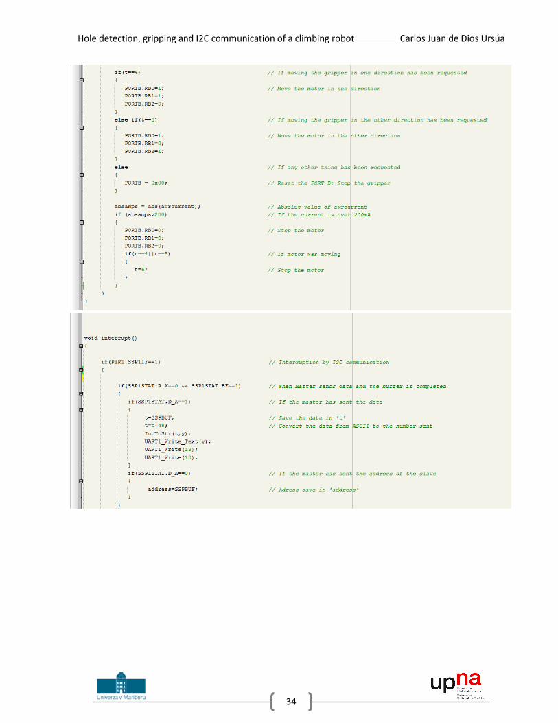
The code of the slave, which is the code of the gripper’s microchip, is much longer because will
join all the previous programs of the project and will prepare to actuate according to the number sent
from the master. For this program, there are going to be two different interruptions, and it is going to be
necessary to define the priority to set the I2C interruption as a High Priority interruption and the Timer2
interruption as a Low Priority Interruption. The code is shown in the Image 29 and then it will be well
explained.

Hole detection, gripping and I2C communication of a climbing robot Carlos Juan de Dios Ursúa
33
Hole detection, gripping and I2C communication of a climbing robot Carlos Juan de Dios Ursúa
34

Hole detection, gripping and I2C communication of a climbing robot Carlos Juan de Dios Ursúa
35

Hole detection, gripping and I2C communication of a climbing robot Carlos Juan de Dios Ursúa
36
Image 29. Slave final program
As this code is much longer and complex than the previous ones, in the Images 30, 31 and 32 are
flow charts that allow to make an idea of how the entire program works. Then, the different parts of the
program will be carefully analyzed using the flow charts and showing the respective code.
First of all, in the Image 30 can be seen the flow chart of the algorithm realized when an
interruption of the Timer 2 occurs (each 1ms).
Image 30. Timer 2 Interruptions Flow Chart

Hole detection, gripping and I2C communication of a climbing robot Carlos Juan de Dios Ursúa
37
The timer 2 interrupts every 1ms and the counters ‘count’ and ‘counter’ are increased and the
current is measured:
Then, when the value of ‘counter’ is 150 (it means each 150 ms), the average of the last 150
current measurements is done:
And when the value of ‘count’ is 1 (each 1 ms), the values of the two distance sensors are
obtained:
The variable ‘interr’ is used to continue with the code in the main program instead of in the
interruptions. It means that also each millisecond, after getting the values from the sensors, the
inclination of the gripper is calculated:
Then, if there are less than 100 measurements (the size of the array), the values obtained are
saved into the arrays s1 and s2 and the variables ‘hole1’ and ‘hole2’ increases if a hole has been detected
and decreases if not:

Hole detection, gripping and I2C communication of a climbing robot Carlos Juan de Dios Ursúa
38
Finally, after 100 measurements (if the size of the arrays is 100), the variables ‘detect1’ and
‘detect2’ determine if there has been a hole under the sensors or not.
The second part of the program comes when the I2C communication interrupts. The algorithm of
the code in that case is resumed in the Image 31 and, then, it will be carefully explained using code
fragments.
Image 31. I2C Interruptions Flow Chart
When the I2C interruption occurs is because the master wants to communicate with the slave and
there are two options. The first one is that the master is sending data to the slave and, in this case, is

Hole detection, gripping and I2C communication of a climbing robot Carlos Juan de Dios Ursúa
39
necessary to distinguish if it has been sent the address of the slave or a data byte. If the address has been
sent, the value is saved into the variable ‘address’ and if a data byte has been sent, the value is saved into
the variable ‘t’ and then is subtracted 48 to convert from the ASCII code to the equivalent number:
The second option is that the master is requesting for data. In this case, the data sent to the
master will depend on the last value received from it. If the last value received was a ‘1’, the slave would
send to the master a ‘0’ if the sensor 1 didn’t detected a hole and a ‘1’ if the sensor 1 detected it. In case
that the last value received from the master was a ‘2’, the same data is sent but related to the sensor 2
instead of the sensor 1. If that value were a ‘3’, the slave would send a ‘0’ if the gripper is leveled, a ‘1’ if
the sensor 1 is nearer to the wall and a ‘2’ if the sensor 2 is nearer than the sensor 1 to the wall. Finally, if
the last value received from the master were different, the slave would send a ‘9’, just to check:

Hole detection, gripping and I2C communication of a climbing robot Carlos Juan de Dios Ursúa
40
Finally, the algorithm of the part of the main program that is in the infinite loop and, as
consequence, is repeated not depending on the interruptions can be seen in the flow chart of the Image
32.
Image 32. Main program Flow Chart
This part of the main program consists just in four ‘if’ structures related to the movement of the
gripper’s motor depending on the last value received from the master and the value of the current. If the
last value received from the master is a 4, the motor will move in one direction:
If that value is a 5, the motor will move in the other direction:

Hole detection, gripping and I2C communication of a climbing robot Carlos Juan de Dios Ursúa
41
If the value is any other, different from a 4 and a 5, the motor will stop:
Finally, when the value of the current increases because the motor has gripped on the hole or
because it has gone completely inside of the gripper structure, the motor is also stopped:

Hole detection, gripping and I2C communication of a climbing robot Carlos Juan de Dios Ursúa
42
7.- OTHER USEFUL PROGRAMS With the previous programs, the objectives of the project are completed, but throughout the
project development, several programs apart from the previously explained have been written. Some of
them were just trials, other are useless but two of them can be interesting for future applications or checks
and they are going to be briefly explained in this section.
Both programs have to see with geometry and calculations from the sensor values. The first of
them will obtain the relative position of any point from the center of the robot, and the second one will
calculate the diameter of the hole.
7.1.- COORDINATES OF ANY POINT Assuming that the robot arm structure is the one shown in the Image 33, where the gripper with
the distance sensor will be in the extreme of the arm and between them and the center of the robot are
two links and two motors, the coordinates of the final point of the arm referred to the center of the robot
are calculated.
Image 33. Robot arm structure
Now that the robot arm is assumed to be as the one exposed in the Image 33, the coordinates of
the gripper referred to the robot center are calculated knowing the angles of the robot and the length of
the links obtaining the next result:
𝑑 = 𝑐 ∗ cos(180 − 𝛼 − 𝛽) = (𝑙 −𝑙 ∗ sin(𝛼)
sin(180 − 𝛼 − 𝛽)) ∗ cos (180 − 𝛼 − 𝛽)

Hole detection, gripping and I2C communication of a climbing robot Carlos Juan de Dios Ursúa
43
𝑦 = 𝑐 ∗ sin(180 − 𝛼 − 𝛽) = (𝑙 −𝑙 ∗ sin(𝛼)
sin(180 − 𝛼 − 𝛽)) ∗ sin (180 − 𝛼 − 𝛽)
𝑥 = 𝑏 + 𝑑 =𝑙 ∗ sin(𝛽)
sin(180 − 𝛼 − 𝛽)+ (𝑙 −
𝑙 ∗ sin(𝛼)
sin(180 − 𝛼 − 𝛽)) ∗ cos (180 − 𝛼 − 𝛽)
With this equations, the coordinates x and y are calculated. It is important to take into account
that these equations could work no matter which coordinate system is taken as a reference, but if some
points are going to be compared, it is important to make sure that all of them are referred to the same
coordinate system. If, for future applications, it is considered important to include this program, it can be
done easily just adding these equations to the algorithm.
7.2.- DIAMETER OF A CIRCLE If there were any situations in which the robot should climb a structure with unknown hole
diameters, it would be interesting to have an algorithm that could measure them. There are two main
ways to measure the diameter using the hole detection and, for both, it will be necessary to detect with
the sensors some points in the border of the hole. The first one is calculating the distance knowing the
time between two borders of a hole and the speed of the movements. The second one is calculating
geometrically knowing the coordinates of some border points referred to the same coordinate system.
However, the first method was discarded because of the difficulty to know the speed of the motors
because there can be some acceleration and nor the speed neither the acceleration have always the same
values. Moreover, it will only be obtained the real value of the diameter if the two border points are
opposite in the circle.
For the second method it would be necessary to use the previous program, to get the coordinates
of every point referred to the same coordinate system. Once the coordinates are obtained, there are two
methods to get the value of the diameter. The first one is calculating the distance between two points
with the next equation, but there is the same problem as the one explained previously, that the points
must be opposite to get the real value of diameter:
𝑑 = √(𝑦1 − 𝑦2)2 + (𝑥1 − 𝑥2)2
Because of the problem explained, the most advisable way to get the value of the diameter is
using three border points, all of them referred to the same coordinate system. Having the three points
(x1,y1), (x2,y2), (x3,y3), the diameter can be calculated in two ways. The first one, geometrically, finding the
intersection of two perpendicular lines to the union between border points, the center of the hole can be
found. With the coordinates of the center and any border point, the radio can be obtained with the
equation above. The drawing of the situation, where the center is found geometrically from three border
holes, is shown in the Image 34, but it won’t be analyzed because the other method will be used.

Hole detection, gripping and I2C communication of a climbing robot Carlos Juan de Dios Ursúa
44
Image 34. Center geometrically found
The other way to find out the diameter of the circle is using the mathematical equation of the
circle. This are the equations of the three points, where xc and yc are the coordinates of the center and R
is the value of the radio:
(𝑥1 − 𝑥𝑐)2 + (𝑦1 − 𝑦𝑐)2 = 𝑅2
(𝑥2 − 𝑥𝑐)2 + (𝑦2 − 𝑦𝑐)2 = 𝑅2
(𝑥3 − 𝑥𝑐)2 + (𝑦3 − 𝑦𝑐)2 = 𝑅2
Now, from these equations xc and yc are cleared, resulting this final expressions:
𝑥𝑐 =(𝑥1
2 − 𝑥32 + 𝑦1
2 − 𝑦32) ∗ (𝑦2 − 𝑦3) − (𝑥2
2 − 𝑥32 + 𝑦2
2 − 𝑦32) ∗ (𝑦1 − 𝑦3)
2 ∗ (𝑥1 − 𝑥3) ∗ (𝑦2 − 𝑦3) − 2 ∗ (𝑥2 − 𝑥3) ∗ (𝑦1 − 𝑦3)
𝑦𝑐 =(𝑥2
2 − 𝑥32 + 𝑦2
2 − 𝑦32) ∗ (𝑥1 − 𝑥3) − (𝑥1
2 − 𝑥32 + 𝑦1
2 − 𝑦32) ∗ (𝑥2 − 𝑥3)
2 ∗ (𝑥1 − 𝑥3) ∗ (𝑦2 − 𝑦3) − 2 ∗ (𝑥2 − 𝑥3) ∗ (𝑦1 − 𝑦3)
With the coordinates of the center and any other point of the border, the radio can be defined
with the equation previously shown that gets the distance between two points.
This is how the diameter of a hole can be calculated from points on the border of the circle than
can be detected with the sensor. With these two programs that can be implemented, if necessary, in
future developments of the robot, this project has reached its end meeting the requirements defined at
the beginning of it.

Hole detection, gripping and I2C communication of a climbing robot Carlos Juan de Dios Ursúa
45
8.- CONCLUSION As conclusion to the project, it must be highlighted that the objectives fixed at the beginning of it
have been successfully achieved, but this is only the beginning of the robot programming because there
are still left various improvements and programs to complete this part of the climbing robot.
8.1.- FUTURE DEVELOPMENTS After this project, the program of the gripper’s microchip is completed, so it is possible to get from
it the information from the sensors and control the gripper’s motor. To get the information from the
sensors, from the gripper’s microchip the information if a hole has been detected by any sensor and if the
gripper is parallel to the wall, is provided to the central microchip using I2C protocol, and the gripper’s
motor can be also controlled from the central microchip.
Now, as has been just commented, the next step will consist in programming the central
microchip that will control the robot movements and will communicate with the grippers’ microchips. The
master algorithm to control the robot movements could be implemented assuming that the robot will
never have more than one arm not gripped on the wall. In this way, the robot will be fixed moving the
only arm possible to find the next grip to fix. To move the robot arms to the next hole is necessary the
program developed by Javier Maquirriain in his Diploma Work [7], which detect the coordinates and the
position of the robot in the wall, as well as the coordinates of the next hole where the not fixed arm of
the robot must grip. To move the robot to that position, is necessary to implement an inverse kinematic
program to obtain the value of the servos’ angles to reach the new position of the robot, where the not
fixed arm is already located in the coordinates of the next hole. Once the not fixed arm is near the new
hole, the robot must locate the gripper in front of the hole to grip on it properly.
During this process, the master will communicate with the not fixed gripper’s microchip and will
ask for information about the hole detection of the sensors. When the gripper is finally in front of the
hole, before gripping, the master will ask the slave to check that the gripper is parallel to the wall, and if
it is not, move it until the inclination is completely reduced. Then, the gripper’s motor is actioned until the
arm is fixed and, then, the process is restarted with another arm.
The last thing to take into account in the future developments of the robot is designing the robot
movements since one sensor detects a hole until the gripper is well located in front of it. The simplest way
to do that, would be saving the relative coordinates when each sensor detects the hole, both referred to
the same coordinate system, and move the robot to the middle to align the hole with the gripper, but it
is not possible to ensure if the gripper will be well located or not. To solve this problem, one option could
be detecting three points in the edge of the hole with each sensor, then the center of both circles would
be calculated as previously explained and, in this case, the point in the middle of the two centers would
be a better and more precise option to locate the gripper.
After using the program from Javier Maquirriain [7], the robot will be located in a point near to
the hole. To find the hole, the robot can move with spiral movements or doing ‘S’, but taking into account
that the distance between line movements must be smaller than the radio of the holes and the speed
enough to detect the holes knowing the time needed to refresh the value of the hole detection.

Hole detection, gripping and I2C communication of a climbing robot Carlos Juan de Dios Ursúa
46
After this brief conclusion and few ideas of future developments of the climbing robot, this project
is concluded.

Hole detection, gripping and I2C communication of a climbing robot Carlos Juan de Dios Ursúa
47
9.- REFERENCES [1] ‘Prijemalo za plezajočega robota’ (Diploma Work) – Tadej Peršak (February 2016)
[2] Microchip web page. 16-bit microcontrollers, dsPIC33F family (July 2016)
http://www.microchip.com/design-centers/16-bit/products/dspic33f-e
[3] Microchip web page. 8-bit microcontrollers, PIC18 family (July 2016)
http://www.microchip.com/ParamChartSearch/chart.aspx?branchID=1004&mid=10&lang=en&
pageId=74
[4] Electroensaimada, I2C (July 2016) http://www.electroensaimada.com/i2c.html
[5] Hinditechy, simple, half and full duplex (July 2016)
http://hinditechy.com/what-is-simplex-half-duplex-and-fu/
[6] I2C info, bus specification (July 2016) http://i2c.info/i2c-bus-specification
[7] ‘Design of programs for localization, direct and inverse kinematic for a climbing robot’ (Diploma
Work) – Javier Maquirriain (July 2016)
[8] ‘Controlling part of a climbing robot for bridge inspection and maintenance’ – Blaž Berden (To
appear in August 2016)
[9] Ponting, Crni Kal viaduct (July 2016) http://www.ponting.si/en/references/bridges-and-
viaducts/viaduct-crni-kal
[10] Sharp sensor GP2Y0A21YK0F (July 2016) http://www.sharpsma.com/webfm_send/1489
[11] Microchip, I2C (July 2016) http://ww1.microchip.com/downloads/en/DeviceDoc/70000195f.pdf