Uncertainty of Temperature measured by Thermocouple
9
Journal of Advanced Research in Fluid Mechanics and Thermal Sciences 68, Issue 1 (2020) 54-62 54 Journal of Advanced Research in Fluid Mechanics and Thermal Sciences Journal homepage: www.akademiabaru.com/arfmts.html ISSN: 2289-7879 Uncertainty of Temperature measured by Thermocouple Yoong Yen Kee 1 , Yutaka Asako 1,* , Tan Lit Ken 1 , Nor Azwadi Che Sidik 1 1 Department of Mechanical Precision Engineering, Malaysia-Japan International Institute of Technology, Universiti Teknologi Malaysia Kuala Lumpur, 54100 Kuala Lumpur, Malaysia ARTICLE INFO ABSTRACT Article history: Received 23 October 2019 Received in revised form 2 January 2020 Accepted 7 January 2020 Available online 25 March 2020 Reliability of data is important for researchers to verify their research result. For temperature measurement involving thermocouple, uncertainty needs to be determined before deciding the reliability of data. In this research, four error sources were proposed to have contributed in the uncertainty of temperature measured by a thermocouple which were resolution limit of data acquisition device, error in temperature measurement based on voltage measurement, reference junction compensation error and data fluctuation. Experiments were carried out to obtain reference junction compensation error and data fluctuation using HIOKI data logger (LR8400-20). The procedure to obtain the uncertainty of the measured temperature including the reference junction compensation uncertainty is proposed. The uncertainty was obtained by combining all the error values with root-sum-square equation. The uncertainty for K thermocouple obtained from this research was 0.42 C. Keywords: Uncertainty; thermocouple; reference junction compensation Copyright © 2020 PENERBIT AKADEMIA BARU - All rights reserved 1. Introduction A thermocouple is a widely used temperature sensor consists of two different electrical conducting wires which shares two connecting junctions. The connecting junctions are known as reference junction (cold junction) and measuring junction (hot junction). Typical connections of a thermocouple are shown in Figure 1. The working principle of a thermocouple is based on Seebeck effect which is a phenomenon where the thermo-electromotive force (EMF) is induced when there is a temperature difference between two junctions [1]. The difference of the electrical potential produced by a thermocouple depends on the difference of the junction temperatures. Therefore, the reference junction temperature should be known to determine the measuring junction temperature. The reference junction used to be placed in an ice-water bath of 0 C as shown in Figure 1(a). However, it is inconvenient to keep the temperature of the ice-water bath 0 C for a long * Corresponding author. E-mail address: [email protected] (Yutaka Asako) https://doi.org/10.37934/arfmts.68.1.5462 Open Access
-
Upload
khangminh22 -
Category
Documents
-
view
0 -
download
0
Transcript of Uncertainty of Temperature measured by Thermocouple

Journal of Advanced Research in Fluid Mechanics and Thermal Sciences 68, Issue 1 (2020) 54-62
54
Journal of Advanced Research in Fluid
Mechanics and Thermal Sciences
Journal homepage: www.akademiabaru.com/arfmts.html ISSN: 2289-7879
Uncertainty of Temperature measured by Thermocouple
Yoong Yen Kee1, Yutaka Asako1,*, Tan Lit Ken1, Nor Azwadi Che Sidik1
1 Department of Mechanical Precision Engineering, Malaysia-Japan International Institute of Technology, Universiti Teknologi Malaysia Kuala
Lumpur, 54100 Kuala Lumpur, Malaysia
ARTICLE INFO ABSTRACT
Article history: Received 23 October 2019 Received in revised form 2 January 2020 Accepted 7 January 2020 Available online 25 March 2020
Reliability of data is important for researchers to verify their research result. For temperature measurement involving thermocouple, uncertainty needs to be determined before deciding the reliability of data. In this research, four error sources were proposed to have contributed in the uncertainty of temperature measured by a thermocouple which were resolution limit of data acquisition device, error in temperature measurement based on voltage measurement, reference junction compensation error and data fluctuation. Experiments were carried out to obtain reference junction compensation error and data fluctuation using HIOKI data logger (LR8400-20). The procedure to obtain the uncertainty of the measured temperature including the reference junction compensation uncertainty is proposed. The uncertainty was obtained by combining all the error values with root-sum-square equation. The uncertainty for K thermocouple obtained from this research was
0.42 C. Keywords: Uncertainty; thermocouple; reference junction compensation Copyright © 2020 PENERBIT AKADEMIA BARU - All rights reserved
1. Introduction
A thermocouple is a widely used temperature sensor consists of two different electrical conducting wires which shares two connecting junctions. The connecting junctions are known as reference junction (cold junction) and measuring junction (hot junction). Typical connections of a thermocouple are shown in Figure 1. The working principle of a thermocouple is based on Seebeck effect which is a phenomenon where the thermo-electromotive force (EMF) is induced when there is a temperature difference between two junctions [1]. The difference of the electrical potential produced by a thermocouple depends on the difference of the junction temperatures. Therefore, the reference junction temperature should be known to determine the measuring junction
temperature. The reference junction used to be placed in an ice-water bath of 0 C as shown in
Figure 1(a). However, it is inconvenient to keep the temperature of the ice-water bath 0 C for a long
* Corresponding author. E-mail address: [email protected] (Yutaka Asako) https://doi.org/10.37934/arfmts.68.1.5462
Open
Access

Journal of Advanced Research in Fluid Mechanics and Thermal Sciences
Volume 68, Issue 1 (2020) 54-62
55
time. Therefore, a data logger has been developed in which the reference junction compensation (RJC) is automatically conducted measuring the terminal temperature in a data logger as shown in Figure 1(b).
(a)
(b)
Fig. 1. Conceptual connection for thermocouple and data logger [2]
The accuracy of the temperature measurement by a thermocouple is provided in a product
specification sheet of a data logger. Examples of manufacturers’ reported accuracy of the temperature measurement with a type T thermocouple are tabulated in Table 1. The resolution is known as the least unit of data that can be obtained by a device and value smaller than that will not be able to record. The EMF of a thermocouple is measured by a voltage measurement unit and the measured voltage is interpreted to the temperature using the inverse polynomials. Therefore, the accuracy of the temperature measurement depends on the accuracy of the voltage measurement. When thermocouple wires are directly connected to the terminal of a data logger, the terminal becomes the reference junction. Therefore, it is necessary to measure the terminal temperature for the RJC. However, as shown in Table 1, the accuracy of the RJC is relatively low.
Table 1 Examples of accuracy of the temperature measurement (T thermocouple)
Accuracy of voltage measurement
Re-solution
Accuracy of temperature measurement
Accuracy of RJC
Total accuracy Ref.
O 20V - 0.1% of rdg 0.5C (0.1% of rdg+0.5C) [3]
K 10V 0.01C - 0.5C - [4]
H 10V 0.01C 0.6C 0.5C 1.1C [5]
E (0.02% of rdg+6V) 0.1C (0.02% of rdg+0.2C) 0.3C (0.02% of rdg+0.5C) [6]
An uncertainty analysis of experimentally measured value is necessary for results to be used to
their fullest value. In the temperature measurement with a thermocouple, a few factors contribute in the uncertainty of the measured temperature. Four factors are considered in this research which are the resolution of a data logger, the accuracy of temperature measurement caused by the accuracy of the voltage measurement, the accuracy of the RJC and the fluctuation of data [2]. The uncertainty based on the resolution and the accuracy of the temperature measurement caused by the voltage measurement is the instrument uncertainty. The uncertainty based on the RJC is the RJC
copper
copper
wire 1
wire 2
data loggeror
volt meter
T2
ice-water
bath, 0C
T1
wire 1
wire 2
data loggerT1
compensation
Journal of Advanced Research in Fluid Mechanics and Thermal Sciences
Volume 68, Issue 1 (2020) 54-62
56
uncertainty. The uncertainty based on the data fluctuation is the random uncertainty. As mentioned
earlier, the accuracy of the RJC listed in Table 1 ranges from 0.3 to 0.5 C and is low comparing with other accuracy. Therefore, measuring the terminal temperatures and the internal terminal temperature, which is used for the RJC, the accuracy of the RJC is assessed. Also, the procedure to obtain the uncertainty of the measured temperature including the RJC uncertainty has not been reported yet. Therefore, in this paper, the procedure to obtain the uncertainty of the measured temperature including the RJC uncertainty is proposed. 2. Experimental Setup
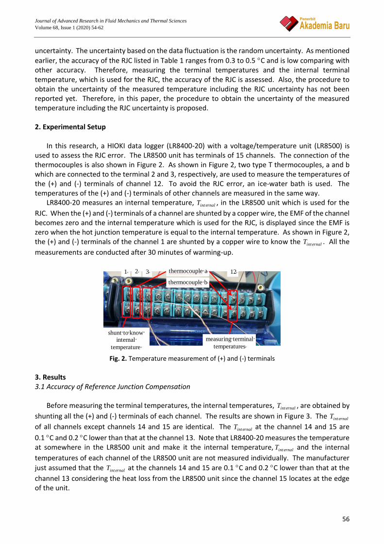
In this research, a HIOKI data logger (LR8400-20) with a voltage/temperature unit (LR8500) is
used to assess the RJC error. The LR8500 unit has terminals of 15 channels. The connection of the thermocouples is also shown in Figure 2. As shown in Figure 2, two type T thermocouples, a and b which are connected to the terminal 2 and 3, respectively, are used to measure the temperatures of the (+) and (-) terminals of channel 12. To avoid the RJC error, an ice-water bath is used. The temperatures of the (+) and (-) terminals of other channels are measured in the same way.
LR8400-20 measures an internal temperature, ernalintT , in the LR8500 unit which is used for the
RJC. When the (+) and (-) terminals of a channel are shunted by a copper wire, the EMF of the channel becomes zero and the internal temperature which is used for the RJC, is displayed since the EMF is zero when the hot junction temperature is equal to the internal temperature. As shown in Figure 2, the (+) and (-) terminals of the channel 1 are shunted by a copper wire to know the ernalintT . All the
measurements are conducted after 30 minutes of warming-up.
Fig. 2. Temperature measurement of (+) and (-) terminals
3. Results 3.1 Accuracy of Reference Junction Compensation
Before measuring the terminal temperatures, the internal temperatures, ernalintT , are obtained by
shunting all the (+) and (-) terminals of each channel. The results are shown in Figure 3. The ernalintT
of all channels except channels 14 and 15 are identical. The ernalintT at the channel 14 and 15 are
0.1 C and 0.2 C lower than that at the channel 13. Note that LR8400-20 measures the temperature at somewhere in the LR8500 unit and make it the internal temperature, ernalintT and the internal
temperatures of each channel of the LR8500 unit are not measured individually. The manufacturer
just assumed that the ernalintT at the channels 14 and 15 are 0.1 C and 0.2 C lower than that at the
channel 13 considering the heat loss from the LR8500 unit since the channel 15 locates at the edge of the unit.
shunt to knowinternal
temperature
measuring terminal
temperatures
thermocouple a
thermocouple b
1 2 3 12

Journal of Advanced Research in Fluid Mechanics and Thermal Sciences
Volume 68, Issue 1 (2020) 54-62
57
Measurements on temperatures at the (+) terminal and the (-) terminal, T and T , and the
internal temperature, ernalintT , were repeated few times. The measured temperatures are plotted in
Figure 4. Temperature differences among the T , T and the terminal temperatures, ernalintT are
observed and also there is the temperature difference between the T and T . However, the
maximum difference between the T and T is less than 0.3 C as seen in Figure 4. Note that the
internal temperatures in Figure 3 are obtained at the same time, however, the terminal temperatures and the internal temperature of each channel in Figure 4 are obtained at different times. Therefore, the internal temperature at each channel is different in Figure 4.
Fig. 3. Internal temperatures at each channel
Fig. 4. Terminal temperatures and internal temperatures
Here we consider a case where the T is higher than the T as shown in Figure 5(a). In such a
case, the EMF is expressed as Recktenwald [7]
T
T
T
TdTSdTSE
H
112 (1)
1 2 3 4 5 6 7 8 9 10 11 12 13 14 1527
27.2
27.4
27.6
27.8
28
channel
Tin
tern
al (
°C)
1 2 3 4 5 6 7 8 9 10 11 12 13 14 15
27
28
channel
Te
mp
. (
°C)
Internal temp. (+) terminal (-) terminal

Journal of Advanced Research in Fluid Mechanics and Thermal Sciences
Volume 68, Issue 1 (2020) 54-62
58
where 12S and 1S are the relative Seebeck coefficient of the thermocouple and absolute Seebeck
coefficient of the wire 1, respectively. Since the maximum difference between the T and T is less
than 0.3 C, we assume that the 1S between the T and T is constant. Then, Eq. (1) can be
rewritten as
TTSdTSEHT
T112 (2)
The rT in Figure 5(b) is the reference temperature under a situation that the EMF is equal to the
EMF calculated from Eq. (2). In such a case, the EMF of the thermocouple is expressed as
r
T
T
T
T
T
TTTSdTSdTSdTSE
H
r
H
12121212 (3)
Substituting Eq. (3) into Eq. (2), the following equation is obtained.
TTS
STTr
12
1 (4)
Note that the values of 12S and 1S depend on the materials of the thermocouple, therefore, the rT
also depends on the type of the thermocouple. Values of 12S and 1S of the K and T thermocouples
at a room temperature are listed in Table 2 [8-9].
(a) (b)
Fig. 5. Conceptual diagram to calculate EMF
Table 2
Relative and absolute Seebeck coefficients of thermocouple K and T [8-9]
Thermocouple 12S (V/K) 1S (V/K)
K 40.5 22.2 T 40.2 1.9
The temperature difference, ernalintr TT , expresses the error of the RJC. The temperature
difference, ernalintr TT , is plotted in Figure 6. The ernalintr TT ranges from -0.31 to 0.21 C for the T
thermocouple and from -0.34 to 0.20 C for the K thermocouple. Therefore, the accuracy of the RJC
T-
T+
Tr
THTHT

Journal of Advanced Research in Fluid Mechanics and Thermal Sciences
Volume 68, Issue 1 (2020) 54-62
59
is 0.31 C for the T thermocouple and 0.34 C for the K thermocouple. The accuracy of the RJC
provided by the manufacturer is 0.5 C. The measured accuracy of the RJC are in the range of the
accuracy provided by the manufacturer. Note that Eq. (4) is also available in the case that the T is
higher than the T .
Fig. 6. Temperature difference between reference and internal temperatures
3.2 Uncertainty of Measured Temperature
Four factors are considered for the uncertainty of measured temperature which are the resolution of a data logger, the accuracy of temperature measurement caused by the accuracy of the voltage measurement, the accuracy of the RJC and the fluctuation of data. 3.2.1 Uncertainty of instrument
The uncertainty of the instrument consists of the resolution of a data logger, the accuracy of
temperature measurement caused by the accuracy of the voltage measurement. Since the HIOKI’s
resolution is 0.01 C based on the specification of the LR8400-20, the uncertainty of the resolution is
0.005 C. The EMF produced by a thermocouple is measured by the voltage measuring unit and the measured voltage is interpreted to the temperature using the inverse polynomials. The accuracy of the voltage measurement is ±10μV based on the specification of the LR8400-20. The inverse polynomials are almost the linear function. Therefore, the conversion coefficients are 0.0251 for the K thermocouple and 0.0259 for the T thermocouple [10]. The uncertainty of temperature measurement is tabulated in Table 3. The uncertainty of the resolution is much smaller than the uncertainty of temperature measurement. Therefore, the uncertainty of the instrument is equal to the uncertainty of temperature measurement.
Table 3 Uncertainty of temperature measurement caused by accuracy of voltage measurement
Accuracy of voltage measurement Thermocouple K Thermocouple T
10 V 0.25 C 0.26 C
1 2 3 4 5 6 7 8 9 10 11 12 13 14 15
-0.4
-0.2
0
0.2
0.4
channel
Tr -
Tin
tern
al (
°C)
T thermocouple K thermocouple

Journal of Advanced Research in Fluid Mechanics and Thermal Sciences
Volume 68, Issue 1 (2020) 54-62
60
3.2.2 Uncertainty of fluctuation The uncertainty of fluctuation was obtained by measuring temperature of a metal block under
controlled surrounding temperature. The 50/60 Hz cut-off filter setting is selected. The measured temperature was plotted in Figure 7. Although the room temperature is controlled, the metal block temperature slightly increases or decreases with time like a temperature drift. Therefore, the temperature drift is expressed by a linear function (a red dashed line in Figure 7) and the temperature fluctuation, 'T , is calculated from the following equation. The linear equation of the temperature
drift is obtained by a curve fitting.
driftmeasured TT'T (5)
Fig. 7. Temperature of a metal block
The temperature fluctuation is plotted in Figure 8 as a function of time. The range of the
uncertainty of the resolution is also plotted in Figure 8. The uncertainty of the resolution is smaller than the fluctuation. The temperature measurements were repeated on different days. The standard deviation of the fluctuation, , is calculated and 2 is chosen for the uncertainty due to the fluctuation and the result is tabulated in Table 4. The uncertainty of random fluctuation is not constant. However, it is much smaller than the uncertainty of the instrument and the uncertainty of the reference junction compensation. This is because the 50/60 Hz cut-off filter setting is selected.
Fig. 8. Graph showing fluctuating data and temperature gap of thermocouple data
0 100 200 30027.1
27.15
27.2
27.25
27.3
t (s)
T (°
C)
Tdrift = 27.24367-2.317703x10⁻⁴
t
0 100 200 300-0.04
-0.02
0
0.02
0.04
time (s)
T '
(°C
)
±2 = ±0.014 °C
uncertainty of resolution

Journal of Advanced Research in Fluid Mechanics and Thermal Sciences
Volume 68, Issue 1 (2020) 54-62
61
Table 4 Uncertainty of random fluctuation obtained on different day
Date 2 (C) Thermocouple K Thermocouple T
25/4/2019 0.0150 0.0286 6/5/2019 0.0137 0.0148 7/5/2019 0.0129 0.0149 9/5/2019 0.0122 0.0156
3.2.3 Overall uncertainty of measured temperature
Overall uncertainties obtained with root-sum-square, Eq. (6), are listed in Table 5. The overall
uncertainties for the K thermocouple and the T thermocouple are ±0.42 C and ±0.40 C, respectively. Random error is too small, and it does not affect overall uncertainty value. The uncertainty of the reference junction compensation is relatively large, the usage of the ice-water bath is recommended in an academic purpose.
222randRJCinsttotal uuuu (6)
Table 5 Overall uncertainty
Thermocouple instu C RJCu C randu C totalu C
K ±0.25 ±0.34 ±0.012 ~ ±0.015 ±0.42 T ±0.26 ±0.31 ±0.015 ~ ±0.029 ±0.40
4. Conclusion
i. Uncertainty of measured temperature by the HIOKI data logger (LR8400-20) is 0.42 C for the
thermocouple K and 0.40 C for the thermocouple T when the RJC is used. This value is much
less than 1.1 C which is reported by the manufacturer and data logger is reliable. ii. The uncertainty of the reference junction compensation is relatively large, the usage of the
ice-water bath is recommended in an academic purpose. Acknowledgement The authors would like to express their appreciation to Takasago Thermal Engineering Co. Ltd., Japan, for providing financial support for this work through Takasago education and research grant (Vote No: 4B365). References [1] Bajzek, Thomas J. "Thermocouples: a sensor for measuring temperature." IEEE Instrumentation & Measurement
Magazine 8, no. 1 (2005): 35-40. https://doi.org/10.1109/MIM.2005.1405922
[2] Recktenwald, Gerald. "Uncertainty estimation and calculation." Dept. of Mechanical Engineering, Portland State Univ., Portland, OR (2006).
[3] Omron, "Datalogger ZR-RX45, " Industrial Automation, Dec 24, 2015. [4] Keyence, "Temperature measurement unit TR-TH08." [5] Hioki, "Memory Hilogger LR8400, LR8401, LR8402 catalog, "
https://www.hioki.com/en/products/detail/?product_key=5613 [6] Etodenki, CADAC21 user's manual, 2010.

Journal of Advanced Research in Fluid Mechanics and Thermal Sciences
Volume 68, Issue 1 (2020) 54-62
62
[7] Recktenwald, Gerald. "Conversion of thermocouple voltage to temperature." Mechanical and Materials Engineering Department, Portland State University, Portland, Oregon (2010).
[8] Bentley, Robin E., ed. Handbook of Temperature Measurement Vol. 3: The Theory and Practice of Thermoelectric Thermometry. Vol. 3. Springer Science & Business Media, 1998.
[9] Auparay, Novela. "Room temperature Seebeck coefficient measurement of metals and semiconductors." Oregon State University 11 (2013): 8-9.
[10] ASTM. A manual on the use of thermocouples in temperature measurement, ASTM Philadelphia, New York, 4thed., 1993.