Type-safe oop with prototypes: the concept of omega
25
GEAR DESIGN STEP 1 INPUT: Blank diameter is 135mm OPERATION : TURNING The Centre Lathe is used to manufacture cylindrical shapes from a range of materials including; steels and plastics. Many of the components that go together to make an engine work have been manufactured using lathes. This type of lathe is controlled by a person turning the various handles on the top slide and cross slide in order to make a product / part.
-
Upload
independent -
Category
Documents
-
view
1 -
download
0
Transcript of Type-safe oop with prototypes: the concept of omega
GEAR DESIGN
STEP 1INPUT:
Blank diameter is 135mm
OPERATION: TURNINGThe Centre Lathe is used to manufacture cylindricalshapes from a range of materials including; steelsand plastics. Many of the components that gotogether to make an engine work have beenmanufactured using lathes. This type of lathe iscontrolled by a person turning the various handleson the top slide and cross slide in order to make aproduct / part.
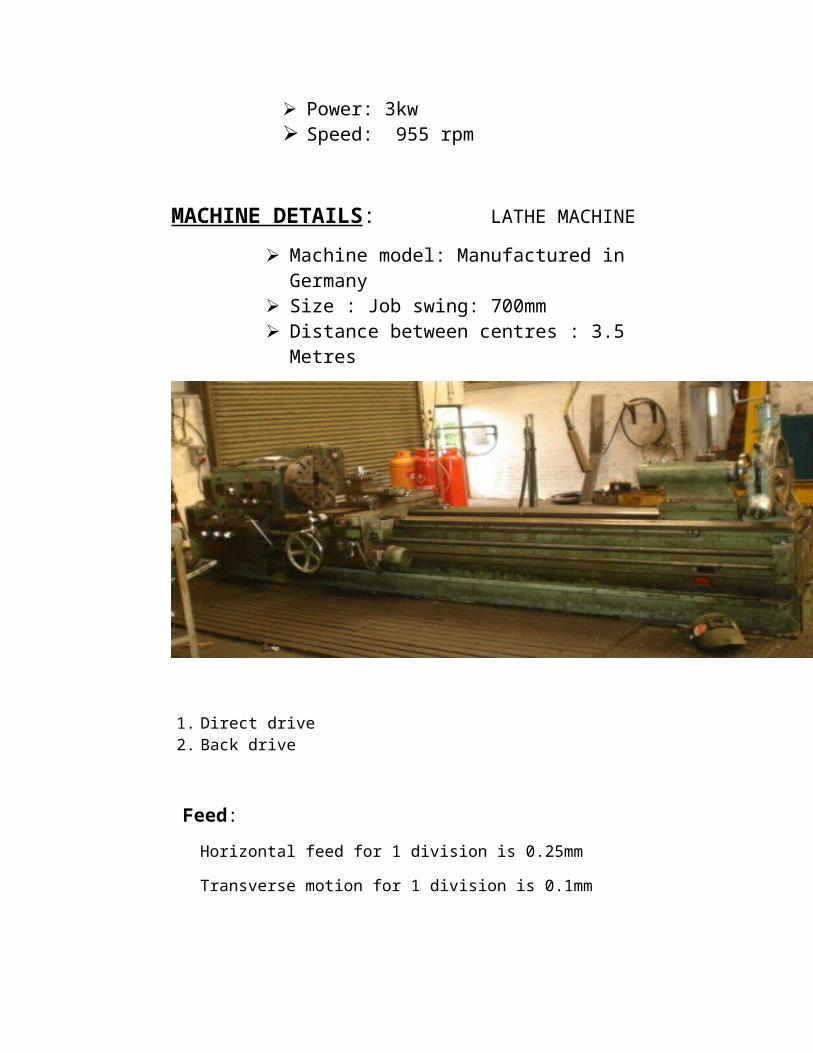
Power: 3kw Speed: 955 rpm
MACHINE DETAILS: LATHE MACHINE Machine model: Manufactured in
Germany Size : Job swing: 700mm Distance between centres : 3.5
Metres
1. Direct drive 2. Back drive
Feed: Horizontal feed for 1 division is 0.25mm
Transverse motion for 1 division is 0.1mm
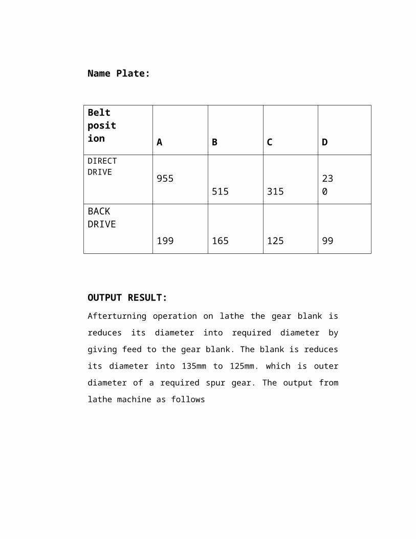
Name Plate:
Belt position
A
B
C
D
DIRECTDRIVE 955
515 315
230
BACK DRIVE
199 165
125
99
OUTPUT RESULT:Afterturning operation on lathe the gear blank is
reduces its diameter into required diameter by
giving feed to the gear blank. The blank is reduces
its diameter into 135mm to 125mm. which is outer
diameter of a required spur gear. The output from
lathe machine as follows
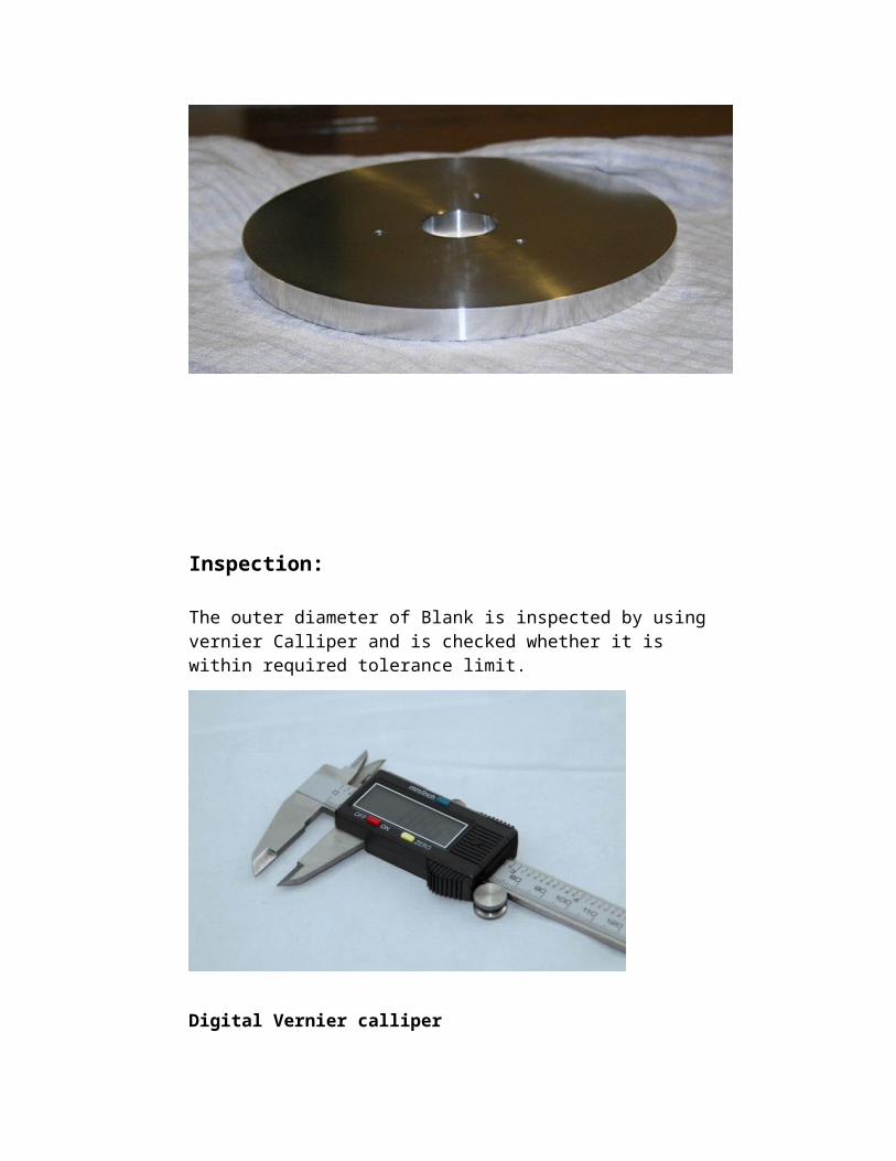
Inspection:
The outer diameter of Blank is inspected by using vernier Calliper and is checked whether it is within required tolerance limit.
Digital Vernier calliper
STEP 2
OPERATION: DRILLING
In this step
drilling can be done.
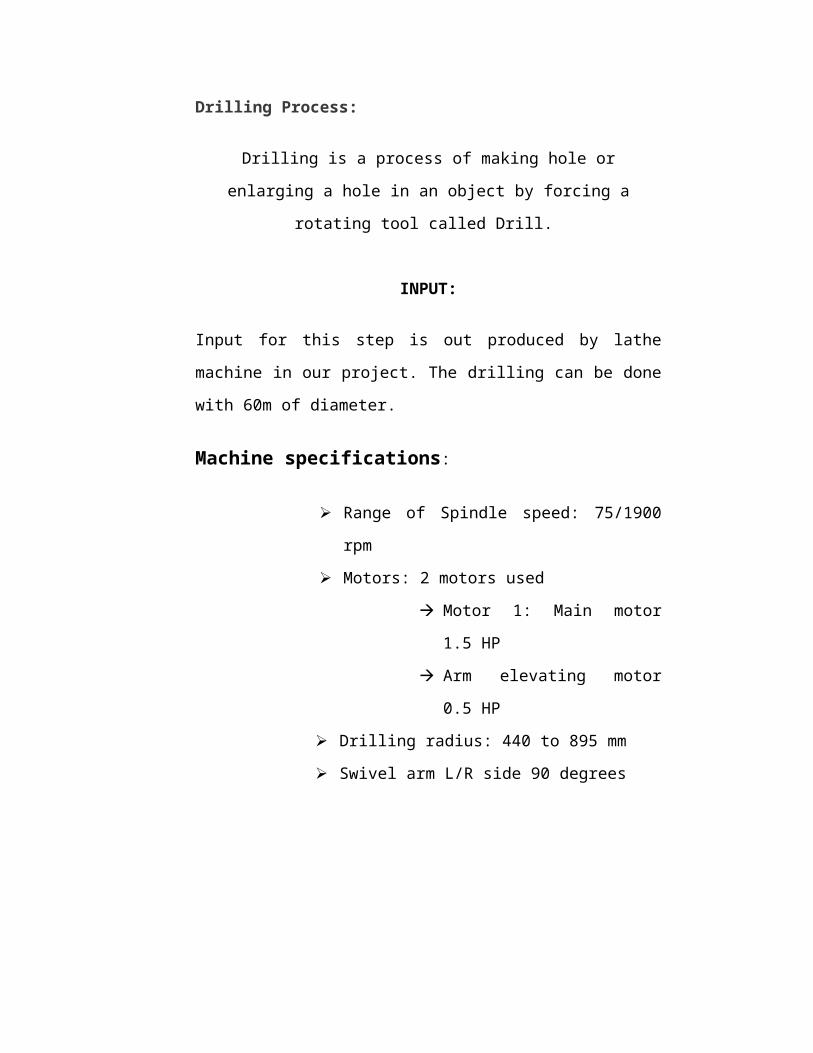
Drilling Process:
Drilling is a process of making hole or
enlarging a hole in an object by forcing a
rotating tool called Drill.
INPUT:
Input for this step is out produced by lathe
machine in our project. The drilling can be done
with 60m of diameter.
Machine specifications:
Range of Spindle speed: 75/1900
rpm
Motors: 2 motors used
Motor 1: Main motor
1.5 HP
Arm elevating motor
0.5 HP
Drilling radius: 440 to 895 mm
Swivel arm L/R side 90 degrees
DRILLING MACHINE
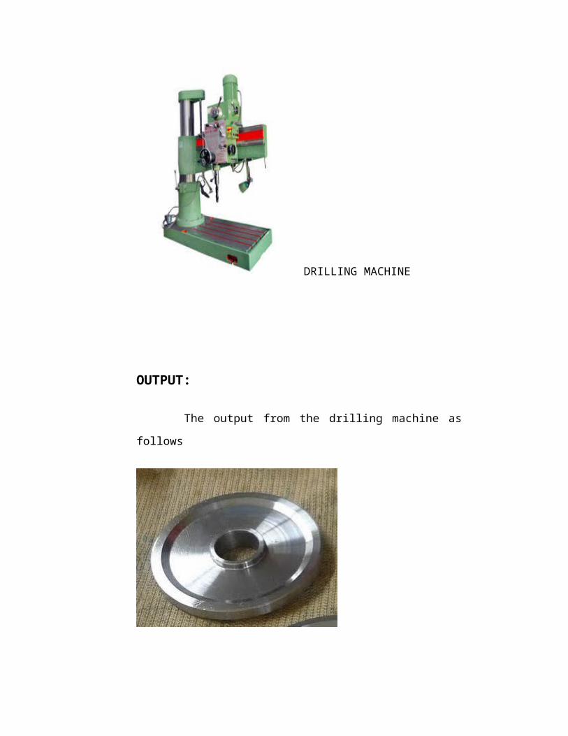
OUTPUT:
The output from the drilling machine as
follows
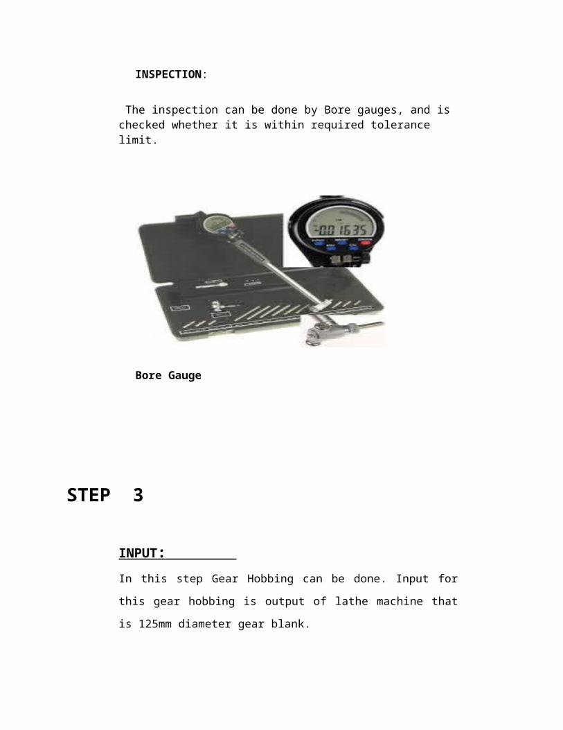
INSPECTION:
The inspection can be done by Bore gauges, and is checked whether it is within required tolerance limit.
Bore Gauge
STEP 3
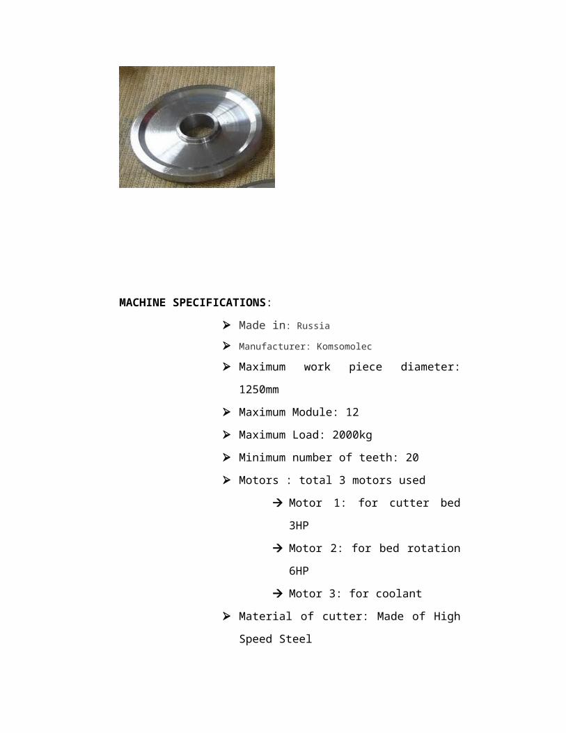
INPUT : In this step Gear Hobbing can be done. Input for
this gear hobbing is output of lathe machine that
is 125mm diameter gear blank.
MACHINE SPECIFICATIONS:
Made in: Russia Manufacturer: Komsomolec
Maximum work piece diameter:
1250mm
Maximum Module: 12
Maximum Load: 2000kg
Minimum number of teeth: 20
Motors : total 3 motors used
Motor 1: for cutter bed
3HP
Motor 2: for bed rotation
6HP
Motor 3: for coolant
Material of cutter: Made of High
Speed Steel
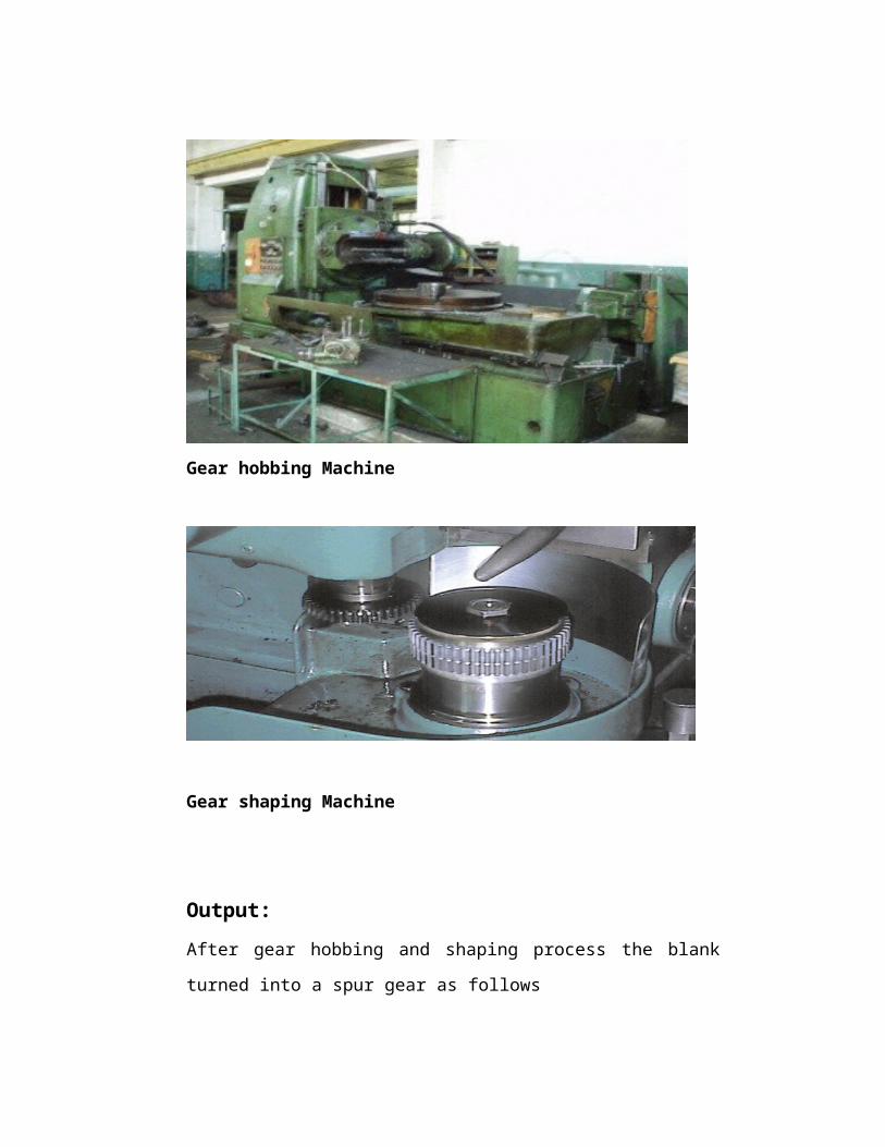
Gear hobbing Machine
Gear shaping Machine
Output:After gear hobbing and shaping process the blank
turned into a spur gear as follows
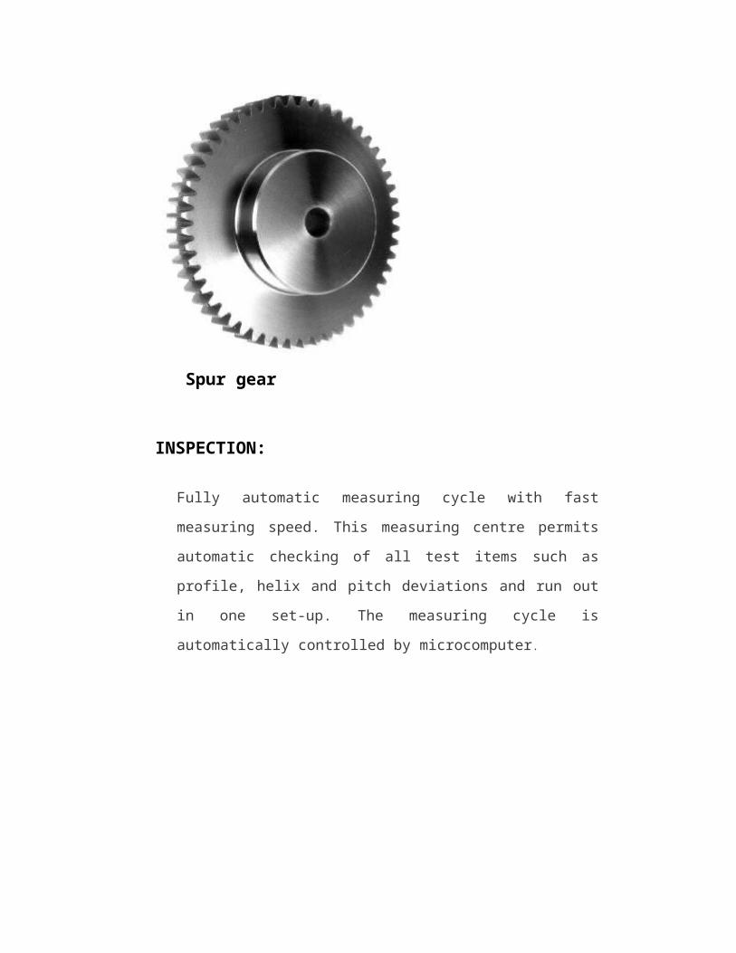
Spur gear
INSPECTION:
Fully automatic measuring cycle with fast
measuring speed. This measuring centre permits
automatic checking of all test items such as
profile, helix and pitch deviations and run out
in one set-up. The measuring cycle is
automatically controlled by microcomputer.
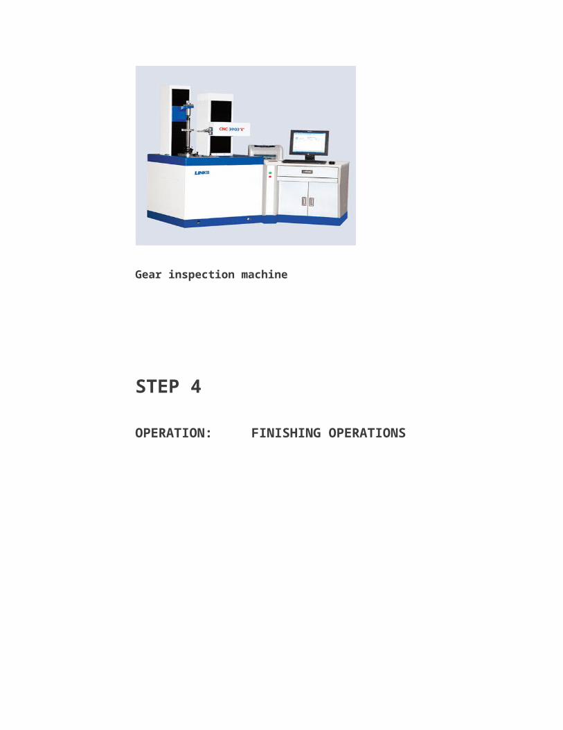
Gear inspection machine
STEP 4
OPERATION: FINISHING OPERATIONS
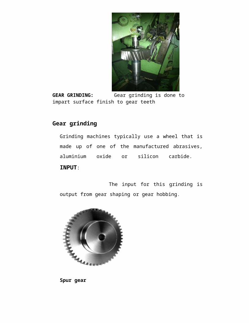
GEAR GRINDING: Gear grinding is done to impart surface finish to gear teeth
Gear grinding
Grinding machines typically use a wheel that is
made up of one of the manufactured abrasives,
aluminium oxide or silicon carbide.
INPUT:
The input for this grinding is
output from gear shaping or gear hobbing.
Spur gear
MACHINE SPECIFICATIONS:
Machine name: HOFLER H 500 Gear
Grinding Machine
Maximum Diameter of Gear: 500
diameter Mm
Gear Width: 250 mm
Max. Module: 10
Min. Module: 2
Table Diameter: 500 mm
OUTPUT: The output from the gear
grinding is final product which customer requires,
and as per the customer requirements. The final
product is packed and dispatched to the customer.
DESIGN OFGEARSGEARS: As the number of teeth on each
gear is also determined, module and facewidth of
each gear pair is to be determined.
The following requirements must be met in the
design of a gear.
The gear teeth have sufficient strength so
that they will not fail under static load or
dynamic load during normal running conditions.
The gear teeth should have wear
characteristics so that their life is
satisfactory.
The use of space and material should be
economical.
The alignment of gears and deflections of the
shafts must be considered because they effect
on the performance of the gears.
The lubrication of gears must be satisfactory.
Gear tooth strength based on Lewis equation
which is most widely used equation to
calculate tooth bending strength. And the wear
strength of a gear based on Buckingham
equation.
Generally with the help of Lewis equation , module
and face width of a gear are kept as variables in
terms of module and substituting all other terms in
the equation , module is obtained by trail and
error method such that the gear can transmit the
required load.
Equations are available to calculate the static
strength, dynamic load and wear strength of gear
tooth. The static strength of the gear should be
greater than the1.25 to 1.5 times the dynamic
strength based on the type of load and the wear
strength should be greater than the dynamic loads.
If the gear with the calculated module and face
width passes these checks, then it is considered to
be safe.
In any spur or helical pair made of same
material, the smaller gear or the pinion is the
weaker of the two. Hence design should be based on
the pinion
The design Equations for spur gear are as follows
Lewis Equation
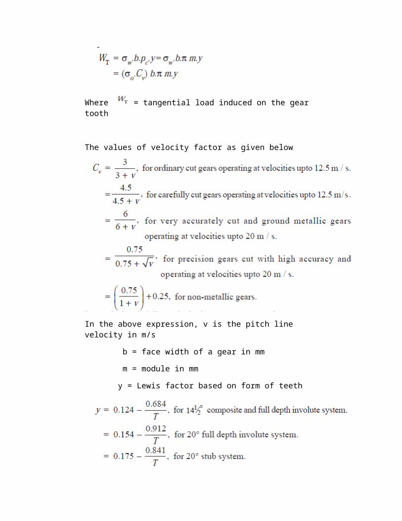
Where = tangential load induced on the gear tooth
The values of velocity factor as given below
In the above expression, v is the pitch line velocity in m/s
b = face width of a gear in mm
m = module in mm
y = Lewis factor based on form of teeth
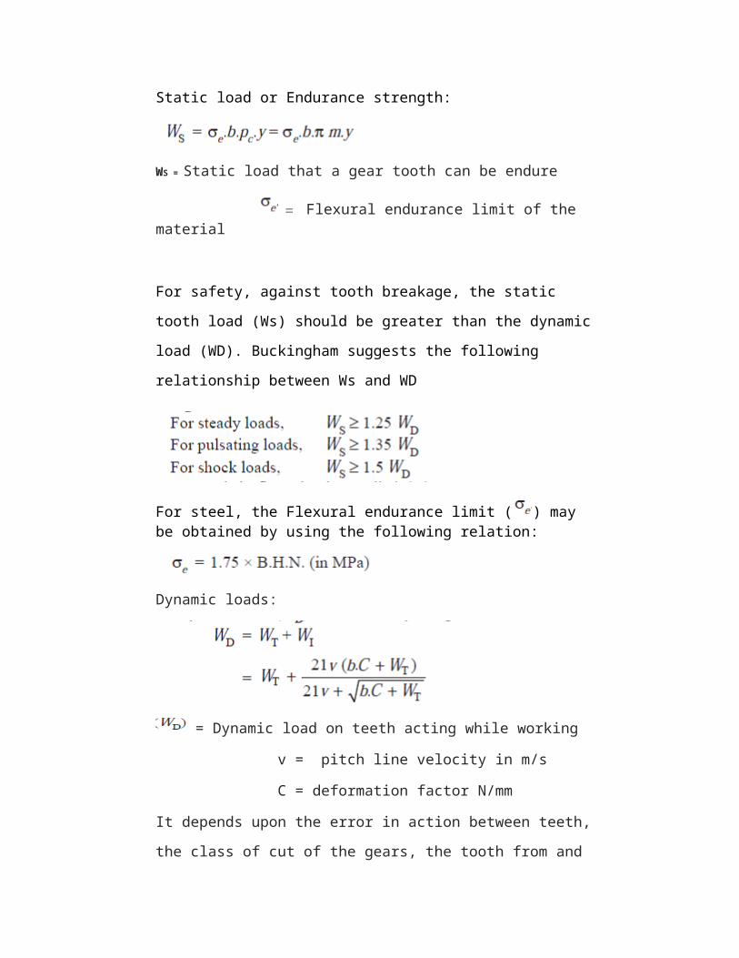
Static load or Endurance strength:
WS = Static load that a gear tooth can be endure
Flexural endurance limit of the material
For safety, against tooth breakage, the static
tooth load (Ws) should be greater than the dynamic
load (WD). Buckingham suggests the following
relationship between Ws and WD
For steel, the Flexural endurance limit ( ) may be obtained by using the following relation:
Dynamic loads:
= Dynamic load on teeth acting while working
v = pitch line velocity in m/s
C = deformation factor N/mm
It depends upon the error in action between teeth,
the class of cut of the gears, the tooth from and
the material of gears, the following table shows
the values of deformation factor ( C ) for checking
the dynamic load on gears.
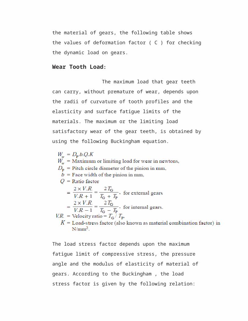
Wear Tooth Load:
The maximum load that gear teeth
can carry, without premature of wear, depends upon
the radii of curvature of tooth profiles and the
elasticity and surface fatigue limits of the
materials. The maximum or the limiting load
satisfactory wear of the gear teeth, is obtained by
using the following Buckingham equation.
The load stress factor depends upon the maximum
fatigue limit of compressive stress, the pressure
angle and the modulus of elasticity of material of
gears. According to the Buckingham , the load
stress factor is given by the following relation:
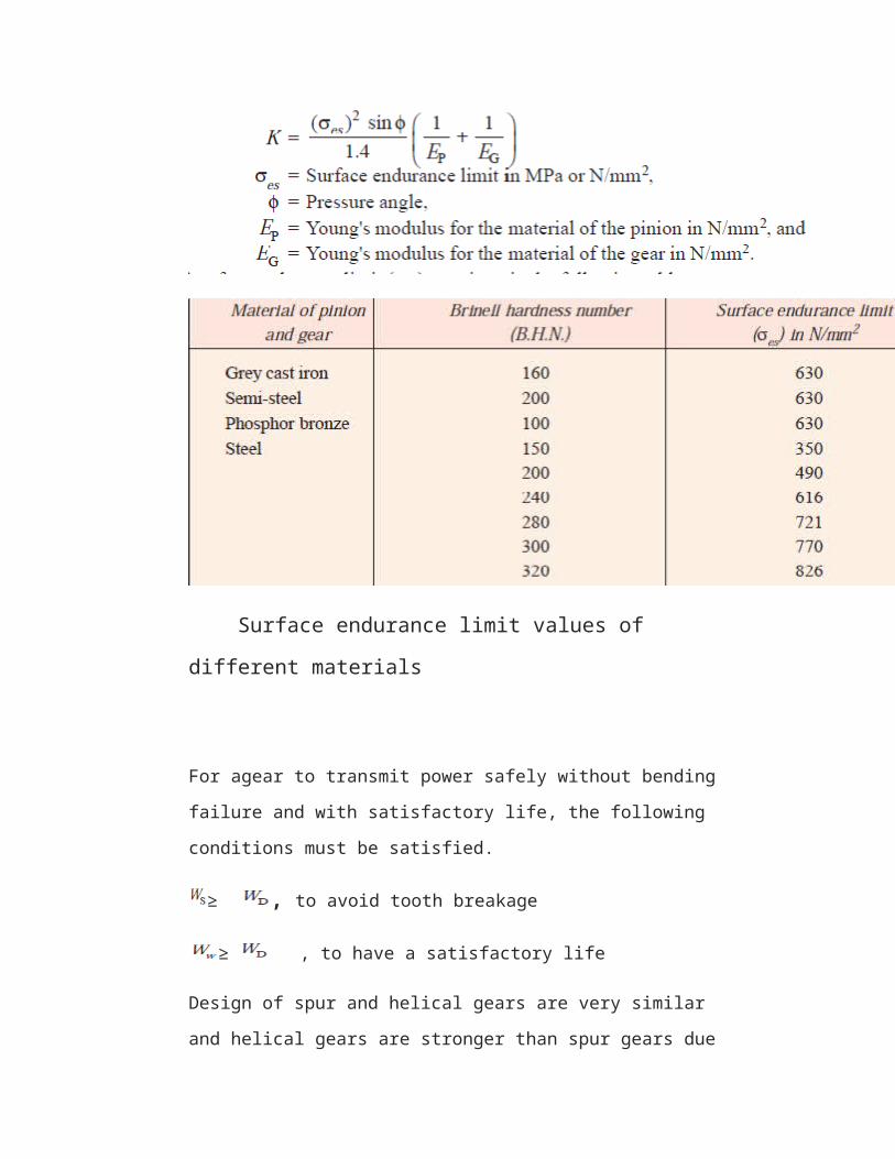
Surface endurance limit values of
different materials
For agear to transmit power safely without bending
failure and with satisfactory life, the following
conditions must be satisfied.
≥ , to avoid tooth breakage
≥ , to have a satisfactory life
Design of spur and helical gears are very similar
and helical gears are stronger than spur gears due
to the fact that the teeth are inclined more than
on tooth are in contact at any given instant.
SPUR GEAR DESIGN
The design calculations for the selected spur gear
system are given below
Input data is
Power to be transmitted P = 50 KW
Hardness of material = 320 BHN
Flexural Endurance strength ( ) = 560 M Pa
Allowable bending stress ( ) =
350 M Pa
Surface Endurance Limit ( ) = 826
M Pa
Velocity ratio is 2
Centre distance L = 600 mm
Pinion rpm = 400 r.p.m
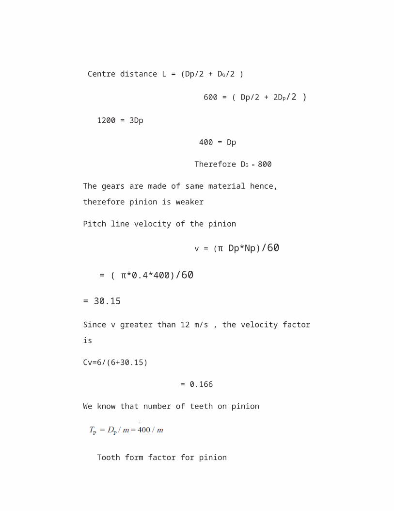
Centre distance L = (Dp/2 + DG/2 )
600 = ( Dp/2 + 2Dp/2 )
1200 = 3Dp
400 = Dp
Therefore DG = 800
The gears are made of same material hence,
therefore pinion is weaker
Pitch line velocity of the pinion
v = (π Dp*Np)/60
= ( π*0.4*400)/60
= 30.15
Since v greater than 12 m/s , the velocity factor
is
Cv=6/(6+30.15)
= 0.166
We know that number of teeth on pinion
Tooth form factor for pinion
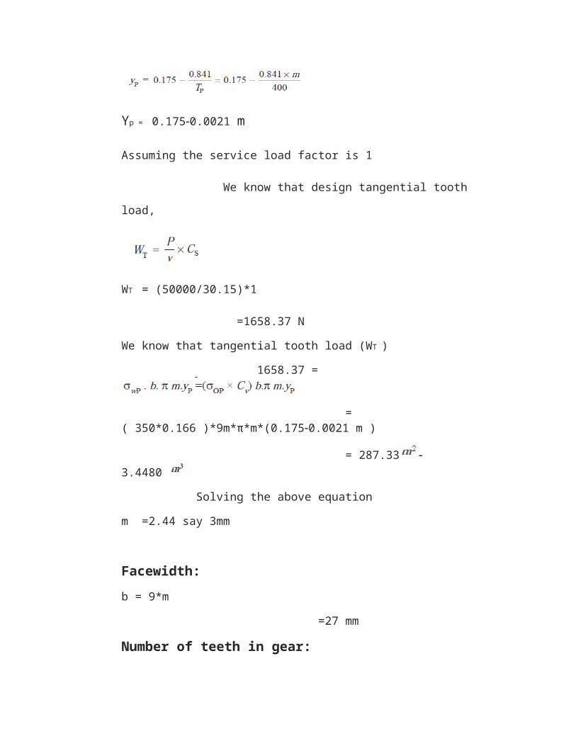
Yp = 0.1750.0021 m
Assuming the service load factor is 1
We know that design tangential tooth
load,
WT = (50000/30.15)*1
=1658.37 N
We know that tangential tooth load (WT )
1658.37 =
= ( 350*0.166 )*9m*π*m*(0.1750.0021 m )
= 287.33 3.4480
Solving the above equation
m =2.44 say 3mm
Facewidth:b = 9*m
=27 mm
Number of teeth in gear:
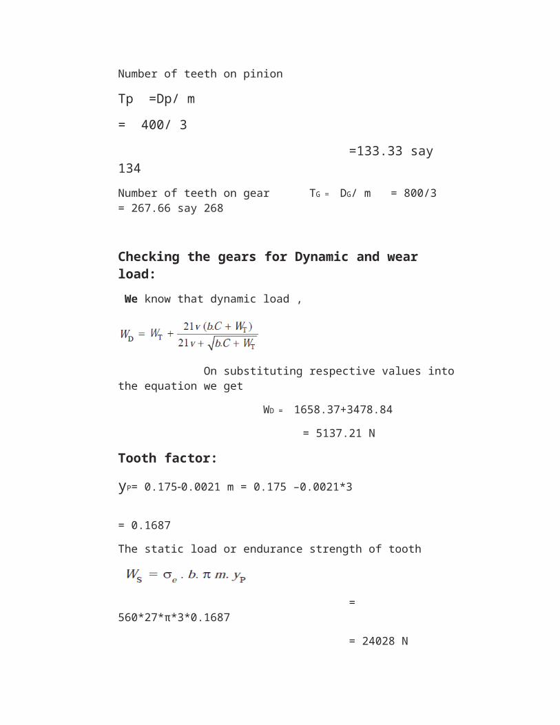
Number of teeth on pinion
Tp =Dp/ m
= 400/ 3
=133.33 say 134Number of teeth on gear TG = DG/ m = 800/3 = 267.66 say 268
Checking the gears for Dynamic and wear load: We know that dynamic load ,
On substituting respective values intothe equation we get
WD = 1658.37+3478.84
= 5137.21 N
Tooth factor:
yP= 0.1750.0021 m = 0.175 –0.0021*3
= 0.1687
The static load or endurance strength of tooth
= 560*27*π*3*0.1687
= 24028 N
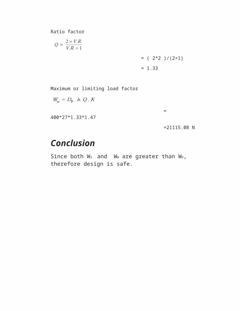
Ratio factor
= ( 2*2 )/(2+1)
= 1.33
Maximum or limiting load factor
= 400*27*1.33*1.47
=21115.08 N
ConclusionSince both WS and WW are greater than WD, therefore design is safe.