Vauxhall/Opel Omega Service and Repair Manual
340
3510 Vauxhall/Opel Omega Vauxhall/Opel Omega Service and Repair Manual Mark Coombs and Spencer Drayton Models covered Vauxhall Omega Saloon and Estate models with petrol engines, including special/limited editions 1998 cc, 2498 cc & 2969 cc petrol engines Does not cover diesel engine or bi-fuel (LPG) models (3510 - 352) ABCDE FGHIJ KLMNO PQRST 1 2 3 © Haynes Publishing 1999 A book in the Haynes Service and Repair Manual Series All rights reserved. No part of this book may be reproduced or transmitted in any form or by any means, electronic or mechanical, including photocopying, recording or by any information storage or retrieval system, without permission in writing from the copyright holder. ISBN 1 850960 510 9 British Library Cataloguing in Publication Data A catalogue record for this book is available from the British Library. Printed by J H Haynes & Co. Ltd, Sparkford, Nr Yeovil, Somerset BA22 7JJ Haynes Publishing Sparkford, Nr Yeovil, Somerset BA22 7JJ, England Haynes North America, Inc 861 Lawrence Drive, Newbury Park, California 91320, USA Editions Haynes S.A. Tour Aurore - La Défense 2, 18 Place des Reflets, 92975 PARIS LA DEFENSE Cedex France Haynes Publishing Nordiska AB Box 1504, 751 45 UPPSALA, Sverige
-
Upload
khangminh22 -
Category
Documents
-
view
0 -
download
0
Transcript of Vauxhall/Opel Omega Service and Repair Manual
3510 Vauxhall/Opel Omega
Vauxhall/Opel OmegaService and Repair ManualMark Coombs and Spencer Drayton
Models covered
Vauxhall Omega Saloon and Estate models with petrol engines, including special/limited editions1998 cc, 2498 cc & 2969 cc petrol engines
Does not cover diesel engine or bi-fuel (LPG) models
(3510 - 352)
ABCDEFGHIJKLMNOPQRST1 2 3
© Haynes Publishing 1999
A book in the Haynes Service and Repair Manual Series
All rights reserved. No part of this book may be reproduced or transmittedin any form or by any means, electronic or mechanical, includingphotocopying, recording or by any information storage or retrieval system,without permission in writing from the copyright holder.
ISBN 1 850960 510 9
British Library Cataloguing in Publication DataA catalogue record for this book is available from the British Library.
Printed by J H Haynes & Co. Ltd, Sparkford, Nr Yeovil, Somerset BA22 7JJ
Haynes PublishingSparkford, Nr Yeovil, Somerset BA22 7JJ, England
Haynes North America, Inc861 Lawrence Drive, Newbury Park, California 91320, USA
Editions Haynes S.A.Tour Aurore - La Défense 2, 18 Place des Reflets, 92975 PARIS LA DEFENSE Cedex France
Haynes Publishing Nordiska ABBox 1504, 751 45 UPPSALA, Sverige

3510 Vauxhall/Opel Omega
ContentsLIVING WITH YOUR VAUXHALL OMEGAIntroduction Page 0•4
Safety First! Page 0•5
Roadside RepairsIntroduction Page 0•6
If your car won’t start Page 0•6
Jump starting Page 0•7
Wheel changing Page 0•8
Identifying leaks Page 0•9
Towing Page 0•9
Weekly ChecksIntroduction Page 0•10
Underbonnet check points Page 0•10
Engine oil level Page 0•11
Coolant level Page 0•11
Brake (and clutch) fluid level Page 0•12
Power steering fluid level Page 0•12
Battery Page 0•13
Electrical systems Page 0•13
Tyre condition and pressure Page 0•14
Tyre tread wear patterns Page 0•14
Washer fluid level Page 0•15
Wiper blades Page 0•15
Lubricants and fluids Page 0•16
Tyre pressures Page 0•17
MAINTENANCE
Routine Maintenance and ServicingServicing specifications Page 1•2
Maintenance schedule Page 1•3
Maintenance procedures Page 1•6

3510 Vauxhall/Opel Omega
ContentsREPAIRS & OVERHAUL
Engine and Associated Systems2.0 litre SOHC engine in-car repair procedures Page 2A•1
2.0 litre DOHC engine in-car repair procedures Page 2B•1
2.5 and 3.0 litre engine in-car repair procedures Page 2C•1
General engine overhaul procedures Page 2D•1
Cooling, heating and ventilation systems Page 3•1
Fuel and exhaust systems Page 4A•1
Emission control systems Page 4B•1
Starting and charging systems Page 5A•1
Ignition system Page 5B•1
TransmissionClutch Page 6•1
Manual transmission Page 7A•1
Automatic transmission Page 7B•1
Final drive, driveshafts and propeller shaft Page 8•1
Brakes and SuspensionBraking system Page 9•1
Suspension and steering Page 10•1
Body equipmentBodywork and fittings Page 11•1
Body electrical system Page 12•1
Wiring Diagrams Page 12•23
REFERENCEDimensions and weights Page REF•1
Conversion Factors Page REF•2
Buying Spare Parts and Vehicle Identification Page REF•3
General Repair Procedures Page REF•4
Jacking and vehicle support Page REF•5
Radio/cassette unit anti-theft system precaution Page REF•5
Tools and working facilities Page REF•6
MOT Test Checks Page REF•8
Fault Finding Page REF•12
Glossary of Technical Terms Page REF•20
Index Page REF•24

0•4 Introduction
3510 Vauxhall/Opel Omega
The Vauxhall Omega was introduced into the UK in April of 1994 as areplacement for the Vauxhall Carlton and Senator. At its launch, theOmega was available in both Saloon and Estate body styles with achoice of either 2.0 litre (1998 cc) or a 2.5 litre (2498 cc) petrol engineboth available with either a 5-speed manual transmission unit or a 4-speed automatic transmission unit. Shortly afterwards a 3.0 (2968 cc)litre petrol engine was also introduced. A 2.5 litre Diesel engine (notcovered in this manual) was also available. The petrol engines are allwell-proven units which are used in many other Vauxhall vehicles; theengine is mounted at the front of vehicle with the transmissionmounted on its rear.
Two versions of the four-cylinder 2.0 litre engine were used; lowspecification vehicles were fitted with a single overhead camshaft(SOHC) 8-valve engine were as all other vehicles were fitted with the
double overhead camshaft (DOHC) 16-valve engine often referred to asthe ECOTEC engine. The 2.5 and 3.0 litre engines are both V6, doubleoverhead camshaft (DOHC) units which are also often referred asECOTEC engines.
All models have fully-independent front and rear suspension and areequipped with front and rear disc brakes.
A wide range of standard and optional equipment is available withinthe range to suit most tastes, including central locking, electricwindows and an electric sunroof. An air conditioning system wasavailable as an option on certain models.
Provided that regular servicing is carried out in accordance with themanufacturer’s recommendations, the vehicle should prove reliableand very economical. The engine compartment is well-designed, andmost of the items requiring frequent attention are easily accessible.
Vauxhall Omega 2.0 16V SelectVauxhall Omega Estate CD
Your Vauxhall Omega manualThe aim of this manual is to help you get the best value from your
vehicle. It can do so in several ways. It can help you decide what workmust be done (even should you choose to get it done by a garage). Itwill also provide information on routine maintenance and servicing, andgive a logical course of action and diagnosis when random faultsoccur. However, it is hoped that you will use the manual by tackling thework yourself. On simpler jobs it may even be quicker than booking thecar into a garage and going there twice, to leave and collect it. Perhapsmost important, a lot of money can be saved by avoiding the costs agarage must charge to cover its labour and overheads.
The manual has drawings and descriptions to show the function ofthe various components so that their layout can be understood. Tasksare described and photographed in a clear step-by-step sequence.
References to the ‘left’ and ‘right’ are in the sense of a person in thedriver’s seat, facing forwards.
AcknowledgementsThanks are due to Champion Spark Plug, who supplied the
illustrations showing spark plug conditions. Certain illustrations are thecopyright of Vauxhall Motors Limited, and are used with theirpermission. Thanks are also due to Draper Tools Limited, whoprovided some of the workshop tools, and to all those people atSparkford who helped in the production of this manual.
We take great pride in the accuracy of information given in thismanual, but vehicle manufacturers make alterations and designchanges during the production run of a particular vehicle of whichthey do not inform us. No liability can be accepted by the authorsor publishers for loss, damage or injury caused by any errors in, oromissions from, the information given.
The Vauxhall Omega Team
Haynes manuals are produced by dedicated andenthusiastic people working in close co-operation. Theteam responsible for the creation of this book included:
Authors Marc CoombsSpencer Drayton
Sub-editor Ian Barnes
Editor & Page Make-up Steve Churchill
Workshop manager Paul Buckland
Photo Scans Steve TanswellJohn Martin
Cover illustration & Line Art Roger Healing
Wiring diagrams Matthew Marke
We hope the book will help you to get the maximumenjoyment from your car. By carrying out routinemaintenance as described you will ensure your car’sreliability and preserve its resale value.

Safety first! 0•5
3510 Vauxhall/Opel Omega
Working on your car can be dangerous.This page shows just some of the potentialrisks and hazards, with the aim of creating asafety-conscious attitude.
General hazardsScalding• Don’t remove the radiator or expansiontank cap while the engine is hot.• Engine oil, automatic transmission fluid orpower steering fluid may also be dangerouslyhot if the engine has recently been running.
Burning• Beware of burns from the exhaust systemand from any part of the engine. Brake discsand drums can also be extremely hotimmediately after use.
Crushing• When working under or neara raised vehicle,alwayssupplement thejack with axlestands, or usedrive-onramps.Neverventureunder a car whichis only supported by a jack.• Take care if loosening or tightening high-torque nuts when the vehicle is on stands.Initial loosening and final tightening should bedone with the wheels on the ground.
Fire• Fuel is highly flammable; fuel vapour isexplosive. • Don’t let fuel spill onto a hot engine. • Do not smoke or allow naked lights(including pilot lights) anywhere near avehicle being worked on. Also beware ofcreating sparks (electrically or by use of tools).• Fuel vapour is heavier than air, so don’twork on the fuel system with the vehicle overan inspection pit.• Another cause of fire is an electricaloverload or short-circuit. Take care whenrepairing or modifying the vehicle wiring.• Keep a fire extinguisher handy, of a typesuitable for use on fuel and electrical fires.
Electric shock• Ignition HTvoltage can bedangerous,especially topeople with heartproblems or apacemaker. Don’twork on or near theignition system withthe engine running orthe ignition switched on.
• Mains voltage is also dangerous. Makesure that any mains-operated equipment iscorrectly earthed. Mains power points shouldbe protected by a residual current device(RCD) circuit breaker.
Fume or gas intoxication • Exhaust fumes arepoisonous; they oftencontain carbonmonoxide, which israpidly fatal if inhaled.Never run theengine in aconfined spacesuch as a garagewith the doors shut.• Fuel vapour is alsopoisonous, as are the vapours from somecleaning solvents and paint thinners.
Poisonous or irritant substances• Avoid skin contact with battery acid andwith any fuel, fluid or lubricant, especiallyantifreeze, brake hydraulic fluid and Dieselfuel. Don’t syphon them by mouth. If such asubstance is swallowed or gets into the eyes,seek medical advice.• Prolonged contact with used engine oil cancause skin cancer. Wear gloves or use abarrier cream if necessary. Change out of oil-soaked clothes and do not keep oily rags inyour pocket.• Air conditioning refrigerant forms apoisonous gas if exposed to a naked flame(including a cigarette). It can also cause skinburns on contact.
Asbestos• Asbestos dust can cause cancer if inhaledor swallowed. Asbestos may be found ingaskets and in brake and clutch linings.When dealing with such components it issafest to assume that they contain asbestos.
Special hazardsHydrofluoric acid• This extremely corrosive acid is formedwhen certain types of synthetic rubber, foundin some O-rings, oil seals, fuel hoses etc, areexposed to temperatures above 4000C. Therubber changes into a charred or stickysubstance containing the acid. Once formed,the acid remains dangerous for years. If itgets onto the skin, it may be necessary toamputate the limb concerned.• When dealing with a vehicle which hassuffered a fire, or with components salvagedfrom such a vehicle, wear protective glovesand discard them after use.
The battery• Batteries contain sulphuric acid, whichattacks clothing, eyes and skin. Take carewhen topping-up or carrying the battery.• The hydrogen gas given off by the batteryis highly explosive. Never cause a spark orallow a naked light nearby. Be careful whenconnecting and disconnecting batterychargers or jump leads.
Air bags• Air bags can cause injury if they go offaccidentally. Take care when removing thesteering wheel and/or facia. Special storageinstructions may apply.
Diesel injection equipment• Diesel injection pumps supply fuel at veryhigh pressure. Take care when working onthe fuel injectors and fuel pipes.
Warning: Never expose the hands,face or any other part of the bodyto injector spray; the fuel can
penetrate the skin with potentially fatalresults.
Remember...DO• Do use eye protection when using powertools, and when working under the vehicle.
• Do wear gloves or use barrier cream toprotect your hands when necessary.
• Do get someone to check periodicallythat all is well when working alone on thevehicle.
• Do keep loose clothing and long hair wellout of the way of moving mechanical parts.
• Do remove rings, wristwatch etc, beforeworking on the vehicle – especially theelectrical system.
• Do ensure that any lifting or jackingequipment has a safe working load ratingadequate for the job.
DON’T• Don’t attempt to lift a heavy componentwhich may be beyond your capability – getassistance.
• Don’t rush to finish a job, or takeunverified short cuts.
• Don’t use ill-fitting tools which may slipand cause injury.
• Don’t leave tools or parts lying aroundwhere someone can trip over them. Mopup oil and fuel spills at once.
• Don’t allow children or pets to play in ornear a vehicle being worked on.
0•6 Roadside repairs
3510 Vauxhall/Opel Omega
The following pages are intended to help in dealing withcommon roadside emergencies and breakdowns. You will findmore detailed fault finding information at the back of themanual, and repair information in the main chapters.
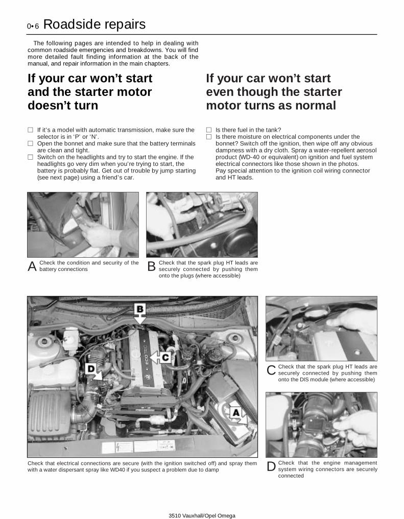
If your car won’t start and the starter motordoesn’t turn
M If it’s a model with automatic transmission, make sure theselector is in ‘P’ or ‘N’.
M Open the bonnet and make sure that the battery terminalsare clean and tight.
M Switch on the headlights and try to start the engine. If theheadlights go very dim when you’re trying to start, thebattery is probably flat. Get out of trouble by jump starting(see next page) using a friend’s car.
If your car won’t start even though the startermotor turns as normal
M Is there fuel in the tank?M Is there moisture on electrical components under the
bonnet? Switch off the ignition, then wipe off any obviousdampness with a dry cloth. Spray a water-repellent aerosolproduct (WD-40 or equivalent) on ignition and fuel systemelectrical connectors like those shown in the photos. Pay special attention to the ignition coil wiring connectorand HT leads.
Check the condition and security of thebattery connectionsA Check that the spark plug HT leads are
securely connected by pushing themonto the plugs (where accessible)
B
Check that the spark plug HT leads aresecurely connected by pushing themonto the DIS module (where accessible)
C
Check that the engine managementsystem wiring connectors are securelyconnected
DCheck that electrical connections are secure (with the ignition switched off) and spray themwith a water dispersant spray like WD40 if you suspect a problem due to damp

Roadside repairs 0•7
3510 Vauxhall/Opel Omega
Jump starting will get you outof trouble, but you must correctwhatever made the battery goflat in the first place. There are three possibilities:
1 The battery has been drained byrepeated attempts to start, or by
leaving the lights on.
2 The charging system is not workingproperly (alternator drivebelt slack
or broken, alternator wiring fault oralternator itself faulty).
3 The battery itself is at fault(electrolyte low, or battery worn out).
Connect one end of the red jump lead tothe positive (+) terminal of the flatbattery
Connect the other end of the red lead tothe positive (+) terminal of the boosterbattery.
Connect one end of the black jump leadto the negative (-) terminal of the boosterbattery
Connect the other end of the black jumplead to a bolt or bracket on the engineblock, well away from the battery, on thevehicle to be started.
1 2 3
4
Make sure that the jump leads will notcome into contact with the fan, drive-belts or other moving parts of theengine.
5
Start the engine using the boosterbattery and run it at idle speed. Switchon the lights, rear window demister andheater blower motor, then disconnectthe jump leads in the reverse order ofconnection. Turn off the lights etc.
6
When jump-starting a car using abooster battery, observe the followingprecautions:
4 Before connecting the boosterbattery, make sure that the ignition isswitched off.
4 Ensure that all electrical equipment(lights, heater, wipers, etc) isswitched off.
4 Take note of any special precautionsprinted on the battery case.
4 Make sure that the booster battery isthe same voltage as the dischargedone in the vehicle.
4 If the battery is being jump-startedfrom the battery in another vehicle,the two vehicles MUST NOT TOUCHeach other.
4 Make sure that the transmission is inneutral (or PARK, in the case ofautomatic transmission).
Jump starting

0•8 Roadside repairs
3510 Vauxhall/Opel Omega
Wheel changingSome of the details shown here will varyaccording to model.
Warning: Do not change a wheel in a situation where you risk being hit byanother vehicle. On busy roads, try to stop in a lay-by or a gateway. Be wary ofpassing traffic while changing the wheel - it is easy to become distracted bythe job in hand.
PreparationM When a puncture occurs, stop as soon as
it is safe to do so.M Park on firm level ground, if possible,
and well out of the way of other traffic.M Use hazard warning lights if necessary.
M If you have one, use a warning triangle toalert other drivers of your presence.
M Apply the handbrake and engage first orreverse gear (or Park on models withautomatic transmission.
M Chock the wheel diagonally opposite theone being removed – a couple of largestones will do for this.
M If the ground is soft, use a flat piece ofwood to spread the load under the jack.
Changing the wheel
On Saloon models unclip the luggagecompartment left-hand trim panel thenrelease the retaining strap and remove
the spare wheel . . .
On Estate models lift up the luggagecompartment floor panel and remove thetools from the centre of the spare wheel.
Undo the retaining nut and remove the sparewheel . . .
. . . The tools and jack are stored in thesmaller compartment on the right-handside of the luggage compartment. Remove
the cover (where fitted) then unscrew the boltand remove the jack and wheelbrace.
1 2 3
. . . then unscrew the retaining bolt andremove the jack from behind the wheel.
On models with steel wheels, use theremoval tool supplied to pull off the wheeltrim and on models with alloy wheels, use
the tool supplied to unscrew the anti-theft boltand remove the hub cap. Slacken each wheelbolt by half a turn.
Unclip the access cover from the sill trimpanel then make sure the jack is locatedon firm ground and engage the jack head
correctly with the lifting point on the sill. Makesure that the lug on the jack head is correctlylocated in the sill seam cutout and the base ofthe jack is directly underneath the sill seam.
4 5
Raise the jack until the wheel is raisedclear of the ground. Unscrew the wheelbolts and remove the wheel. Fit the spare
wheel and screw on the bolts. Lightly tightenthe bolts with the wheelbrace then lower thevehicle to the ground.
Securely tighten the wheel bolts in adiagonal sequence then refit the hubcap/wheel trim (as applicable). Note that
the wheel bolts should be slackened andretightened to the specified torque at theearliest possible opportunity.
7 8
6
Finally...
M Remove the wheel chocks.
M Stow the punctured wheel, jack and toolsin the correct locations in the car.
M Check the tyre pressure on the wheel justfitted. If it is low, or if you don’t have apressure gauge with you, drive slowly tothe nearest garage and inflate the tyre tothe right pressure.
M Have the damaged tyre or wheel repairedas soon as possible.

Roadside repairs 0•9
3510 Vauxhall/Opel Omega
Puddles on the garage floor or drive, orobvious wetness under the bonnet or underneath the car, suggest a leak that needsinvestigating. It can sometimes be difficult todecide where the leak is coming from,especially if the engine bay is very dirtyalready. Leaking oil or fluid can also be blownrearwards by the passage of air under the car,giving a false impression of where theproblem lies.
Warning: Most automotive oilsand fluids are poisonous. Washthem off skin, and change outof contaminated clothing,without delay.
Identifying leaksThe smell of a fluid leakingfrom the car may provide aclue to what’s leaking. Somefluids are distictively coloured.
It may help to clean the car carefullyand to park it over some clean paperovernight as an aid to locating thesource of the leak.Remember that some leaks may onlyoccur while the engine is running.
Sump oil Gearbox oil
Brake fluid Power steering fluid
Oil from filter
Antifreeze
Engine oil may leak from the drain plug... ...or from the base of the oil filter.
Leaking antifreeze often leaves a crystallinedeposit like this.
Gearbox oil can leak from the seals at theinboard ends of the driveshafts.
A leak occurring at a wheel is almostcertainly brake fluid.
Power steering fluid may leak from the pipeconnectors on the steering rack.
When all else fails, you may find yourselfhaving to get a tow home – or of course youmay be helping somebody else. Long-distancerecovery should only be done by a garage orbreakdown service. For shorter distances, DIYtowing using another car is easy enough, butobserve the following points:
M Use a proper tow-rope – they are notexpensive. The vehicle being towed mustdisplay an ‘ON TOW’ sign in its rear window.M Always turn the ignition key to the ‘on’position when the vehicle is being towed, so
that the steering lock is released, and that thedirection indicator and brake lights will work.M Both front and rear towing eyes areprovided. They are located behind the accesscovers on the front and rear bumper.M Before being towed, release the handbrakeand select neutral on the transmission.M Note that greater-than-usual pedalpressure will be required to operate thebrakes, since the vacuum servo unit is onlyoperational with the engine running.M On models with power steering, greater-
than-usual steering effort will also be required.M The driver of the car being towed mustkeep the tow-rope taut at all times to avoidsnatching.M Make sure that both drivers know the routebefore setting off.M Only drive at moderate speeds and keepthe distance towed to a minimum. Drivesmoothly and allow plenty of time for slowingdown at junctions.M On models with automatic transmission,special precautions apply. If in doubt, do nottow, or transmission damage may result.
Towing

0•10 Weekly checks
3510 Vauxhall/Opel Omega
There are some very simple checks whichneed only take a few minutes to carry out, butwhich could save you a lot of inconvenienceand expense.
These "Weekly checks" require no great skillor special tools, and the small amount of timethey take to perform could prove to be verywell spent, for example;
M Keeping an eye on tyre condition andpressures, will not only help to stop themwearing out prematurely, but could also saveyour life.
M Many breakdowns are caused by electricalproblems. Battery-related faults are particularlycommon, and a quick check on a regular basiswill often prevent the majority of these.
M If your car develops a brake fluid leak, thefirst time you might know about it is whenyour brakes don't work properly. Checkingthe level regularly will give advance warning ofthis kind of problem.
M If the oil or coolant levels run low, the costof repairing any engine damage will be fargreater than fixing the leak, for example.
Introduction
§ 2.0 litre DOHCengine
A Engine oil level dipstick
B Engine oil filler cap
C Coolant expansion tank
D Brake (and clutch) fluid
reservoir
E Battery
F Power steering fluid reservoir
Underbonnet check points
§ 2.5 and 3.0 litre engine
A Engine oil level dipstick
B Engine oil filler cap
C Coolant expansion tank
D Brake (and clutch) fluid
reservoir
E Battery
F Power steering fluid reservoir
G Screen washer fluid reservoir
Weekly checks 0•11
3510 Vauxhall/Opel Omega
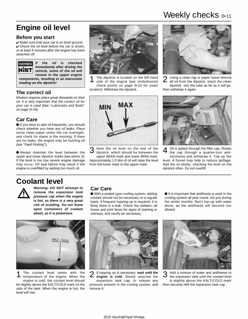
Engine oil levelBefore you start4 Make sure that your car is on level ground.4 Check the oil level before the car is driven,or at least 5 minutes after the engine has beenswitched off.
The correct oilModern engines place great demands on theiroil. It is very important that the correct oil foryour car is used (See “Lubricants and fluids”on page 0•16).
Car Carel If you have to add oil frequently, you shouldcheck whether you have any oil leaks. Placesome clean paper under the car overnight,and check for stains in the morning. If thereare no leaks, the engine may be burning oil(see “Fault Finding”).
l Always maintain the level between theupper and lower dipstick marks (see photo 3).If the level is too low severe engine damagemay occur. Oil seal failure may result if theengine is overfilled by adding too much oil.
If the oil is checkedimmediately after driving thevehicle, some of the oil willremain in the upper engine
components, resulting in an inaccuratereading on the dipstick!
The dipstick is located on the left-handside of the engine (see Underbonnetcheck points on page 0•10 for exact
location). Withdraw the dipstick.
Using a clean rag or paper towel removeall oil from the dipstick. Insert the cleandipstick into the tube as far as it will go,
then withdraw it again.
Note the oil level on the end of thedipstick, which should be between theupper (MAX) mark and lower (MIN) mark.
Approximately 1.0 litre of oil will raise the levelfrom the lower mark to the upper mark.
Oil is added through the filler cap. Rotatethe cap through a quarter-turn anti-clockwise and withdraw it. Top-up the
level. A funnel may help to reduce spillage.Add the oil slowly, checking the level on thedipstick often. Do not overfill.
1 2
3 4
Warning: DO NOT attempt toremove the expansion tankpressure cap when the engineis hot, as there is a very greatrisk of scalding. Do not leaveopen containers of coolantabout, as it is poisonous.
Car Carel With a sealed-type cooling system, addingcoolant should not be necessary on a regularbasis. If frequent topping-up is required, it islikely there is a leak. Check the radiator, allhoses and joint faces for signs of staining orwetness, and rectify as necessary.
l It is important that antifreeze is used in thecooling system all year round, not just duringthe winter months. Don’t top-up with wateralone, as the antifreeze will become toodiluted.
Coolant level
The coolant level varies with thetemperature of the engine. When theengine is cold, the coolant level should
be slightly above the KALT/COLD mark on theside of the tank. When the engine is hot, thelevel will rise.
If topping up is necessary, wait until theengine is cold. Slowly unscrew theexpansion tank cap, to release any
pressure present in the cooling system, andremove it.
Add a mixture of water and antifreeze tothe expansion tank until the coolant levelis slightly above the KALT/COLD mark
then securely refit the expansion tank cap.
1 2 3
0•12 Weekly checks
3510 Vauxhall/Opel Omega
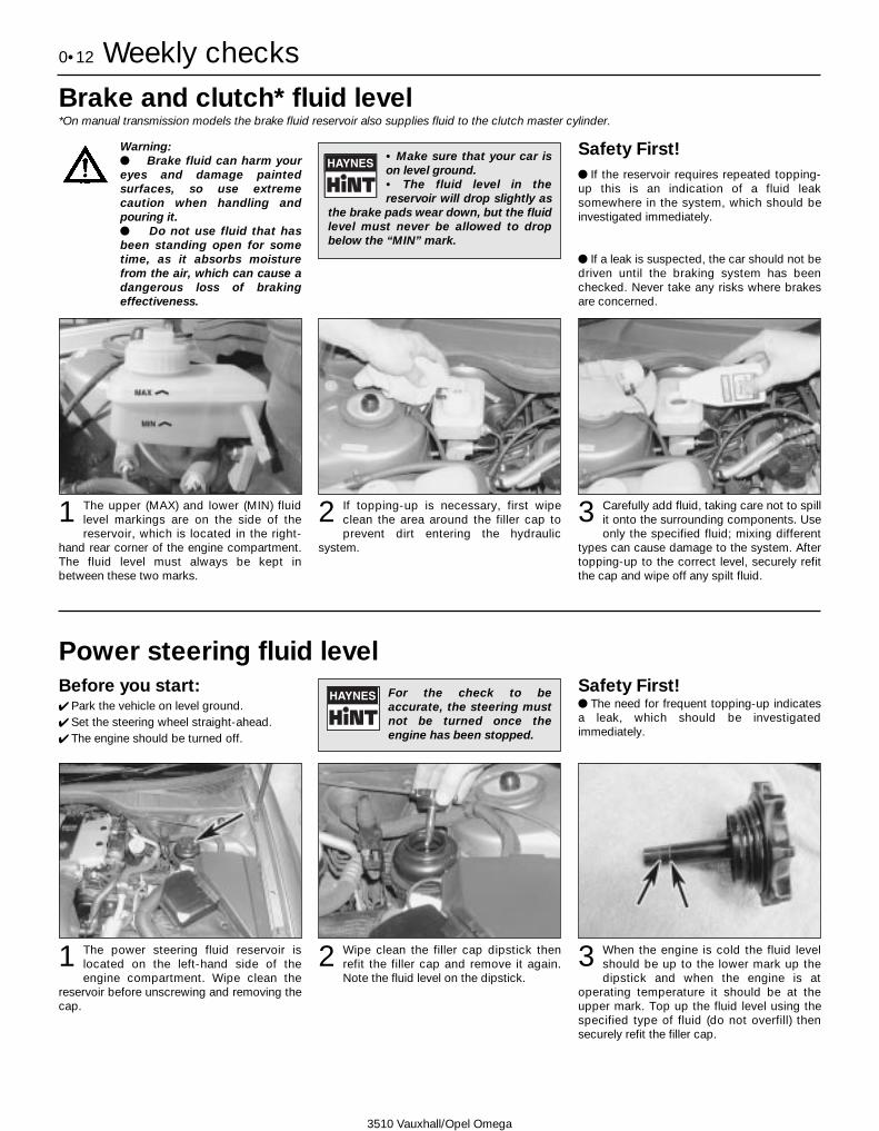
Brake and clutch* fluid level*On manual transmission models the brake fluid reservoir also supplies fluid to the clutch master cylinder.
Warning:l Brake fluid can harm youreyes and damage paintedsurfaces, so use extremecaution when handling andpouring it.l Do not use fluid that hasbeen standing open for sometime, as it absorbs moisturefrom the air, which can cause adangerous loss of brakingeffectiveness.
Safety First!l If the reservoir requires repeated topping-up this is an indication of a fluid leaksomewhere in the system, which should beinvestigated immediately.
l If a leak is suspected, the car should not bedriven until the braking system has beenchecked. Never take any risks where brakesare concerned.
• Make sure that your car ison level ground.• The fluid level in thereservoir will drop slightly as
the brake pads wear down, but the fluidlevel must never be allowed to dropbelow the “MIN” mark.
The upper (MAX) and lower (MIN) fluidlevel markings are on the side of thereservoir, which is located in the right-
hand rear corner of the engine compartment.The fluid level must always be kept inbetween these two marks.
1 If topping-up is necessary, first wipeclean the area around the filler cap toprevent dirt entering the hydraulic
system.
2 Carefully add fluid, taking care not to spillit onto the surrounding components. Useonly the specified fluid; mixing different
types can cause damage to the system. Aftertopping-up to the correct level, securely refitthe cap and wipe off any spilt fluid.
3
Power steering fluid levelBefore you start:4 Park the vehicle on level ground.4 Set the steering wheel straight-ahead.4 The engine should be turned off.
Safety First! l The need for frequent topping-up indicatesa leak, which should be investigatedimmediately.
For the check to beaccurate, the steering mustnot be turned once theengine has been stopped.
The power steering fluid reservoir islocated on the left-hand side of theengine compartment. Wipe clean the
reservoir before unscrewing and removing thecap.
1 Wipe clean the filler cap dipstick thenrefit the filler cap and remove it again.Note the fluid level on the dipstick.
2 When the engine is cold the fluid levelshould be up to the lower mark up thedipstick and when the engine is at
operating temperature it should be at theupper mark. Top up the fluid level using thespecified type of fluid (do not overfill) thensecurely refit the filler cap.
3

Weekly checks 0•13
3510 Vauxhall/Opel Omega
BatteryCaution: Before carrying out any work on thevehicle battery, read the precautions given in"Safety first" at the start of this manual.4 Make sure that the battery tray is in goodcondition, and that the clamp is tight.Corrosion on the tray, retaining clamp and thebattery itself can be removed with a solutionof water and baking soda. Thoroughly rinse allcleaned areas with water. Any metal partsdamaged by corrosion should be coveredwith a zinc-based primer, then painted.4 Periodically (approximately every threemonths), check the charge condition of thebattery as described in Chapter 5A.4 If the battery is flat, and you need to jumpstart your vehicle, see Roadside Repairs.
The battery is located at the front left-hand corner of the engine compartment.If necessary, unclip the fusible link
housing (where fitted) from side of the relaybox then open up the insulating cover to gainaccess to the battery.
1 The exterior of the battery should beinspected periodically for damage suchas a cracked case or cover. Check the
battery lead clamps for tightness to ensuregood electrical connections and check theleads for signs of damage.
2
Battery corrosion can be kept to aminimum by applying a layer ofpetroleum jelly to the clamps andterminals after they are reconnected.
If corrosion (white, fluffy deposits) isevident, remove the cables from thebattery terminals, clean them with a small
wire brush, then refit them. Automotive storessell a tool for cleaning the battery post . . .
3 . . . as well as the battery cable clamps4
Electrical systems4 Check all external lights and the horn. Referto the appropriate Sections of Chapter 12 fordetails if any of the circuits are found to beinoperative.
4 Visually check all accessible wiringconnectors, harnesses and retaining clips forsecurity, and for signs of chafing or damage.
If you need to check yourbrake lights and indicatorsunaided, back up to a wall orgarage door and operate the
lights. The reflected light should show ifthey are working properly.
If a single indicator light, stop-light orheadlight has failed, it is likely that a bulbhas blown and will need to be replaced.
Refer to Chapter 12 for details. If both stoplights have failed, it is possible that the switchhas failed (see Chapter 12, Section 4).
If more than one indicator light or tail lighthas failed it is likely that either a fuse hasblown or that there is a fault in the circuit
(see Chapter 12). Most fuses are located behindin the fusebox, behind the cover on the driver’sside of the facia; depress the locking button andremove the cover to gain access. Additionalfuses can be found in the engine compartmentrelay box and fusible link housing.
2 To replace a blown fuse, remove it, whereapplicable, using the plastic toolprovided. Fit a new fuse of the same
rating, available from car accessory shops. Itis important that you find the reason that thefuse blew (see Electrical fault finding inChapter 12).
31

0•14 Weekly checks
3510 Vauxhall/Opel Omega
Tyre condition and pressureIt is very important that tyres are in goodcondition, and at the correct pressure - havinga tyre failure at any speed is highly dangerous.Tyre wear is influenced by driving style - harshbraking and acceleration, or fast cornering,will all produce more rapid tyre wear. As ageneral rule, the front tyres wear out fasterthan the rears. Interchanging the tyres fromfront to rear ("rotating" the tyres) may result inmore even wear. However, if this iscompletely effective, you may have theexpense of replacing all four tyres at once!Remove any nails or stones embedded in thetread before they penetrate the tyre to causedeflation. If removal of a nail does reveal that
the tyre has been punctured, refit the nail sothat its point of penetration is marked. Thenimmediately change the wheel, and have thetyre repaired by a tyre dealer.Regularly check the tyres for damage in theform of cuts or bulges, especially in thesidewalls. Periodically remove the wheels,and clean any dirt or mud from the inside andoutside surfaces. Examine the wheel rims forsigns of rusting, corrosion or other damage.Light alloy wheels are easily damaged by"kerbing" whilst parking; steel wheels mayalso become dented or buckled. A new wheelis very often the only way to overcome severedamage.
New tyres should be balanced when they arefitted, but it may become necessary to re-balance them as they wear, or if the balanceweights fitted to the wheel rim should fall off.Unbalanced tyres will wear more quickly, aswill the steering and suspension components.Wheel imbalance is normally signified byvibration, particularly at a certain speed(typically around 50 mph). If this vibration isfelt only through the steering, then it is likelythat just the front wheels need balancing. If,however, the vibration is felt through thewhole car, the rear wheels could be out ofbalance. Wheel balancing should be carriedout by a tyre dealer or garage.
Tread Depth - visual checkThe original tyres have tread wear safety
bands (B), which will appear when the treaddepth reaches approximately 1.6 mm. Theband positions are indicated by a triangularmark on the tyre sidewall (A).
1 Tread Depth - manual checkAlternatively, tread wear can be
monitored with a simple, inexpensive deviceknown as a tread depth indicator gauge.
2 Tyre Pressure CheckCheck the tyre pressures regularly with
the tyres cold. Do not adjust the tyrepressures immediately after the vehicle hasbeen used, or an inaccurate setting will result.Tyre pressures are shown on page 0•17.
3
Tyre tread wear patterns
Shoulder Wear
Underinflation (wear on both sides)Under-inflation will cause overheating of thetyre, because the tyre will flex too much, andthe tread will not sit correctly on the roadsurface. This will cause a loss of grip andexcessive wear, not to mention the danger ofsudden tyre failure due to heat build-up.Check and adjust pressuresIncorrect wheel camber (wear on one side)Repair or renew suspension partsHard corneringReduce speed!
Centre Wear
OverinflationOver-inflation will cause rapid wear of thecentre part of the tyre tread, coupled withreduced grip, harsher ride, and the danger ofshock damage occurring in the tyre casing.Check and adjust pressures
If you sometimes have to inflate your car’styres to the higher pressures specified formaximum load or sustained high speed, don’tforget to reduce the pressures to normalafterwards.
Uneven Wear
Front tyres may wear unevenly as a result ofwheel misalignment. Most tyre dealers andgarages can check and adjust the wheelalignment (or "tracking") for a modest charge.Incorrect camber or castorRepair or renew suspension partsMalfunctioning suspensionRepair or renew suspension partsUnbalanced wheelBalance tyresIncorrect toe settingAdjust front wheel alignmentNote: The feathered edge of the tread whichtypifies toe wear is best checked by feel.
Weekly checks 0•15
3510 Vauxhall/Opel Omega
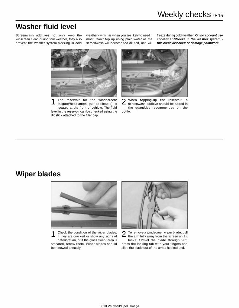
Wiper blades
Check the condition of the wiper blades;if they are cracked or show any signs ofdeterioration, or if the glass swept area is
smeared, renew them. Wiper blades shouldbe renewed annually.
1 To remove a windscreen wiper blade, pullthe arm fully away from the screen until itlocks. Swivel the blade through 90°,
press the locking tab with your fingers andslide the blade out of the arm’s hooked end.
2
Screenwash additives not only keep thewinscreen clean during foul weather, they alsoprevent the washer system freezing in cold
weather - which is when you are likely to need itmost. Don’t top up using plain water as thescreenwash will become too diluted, and will
freeze during cold weather. On no account usecoolant antifreeze in the washer system -this could discolour or damage paintwork.
Washer fluid level
When topping-up the reservoir, ascreenwash additive should be added inthe quantities recommended on the
bottle.
2The reservoir for the windscreen/tailgate/headlamps (as applicable) islocated at the front of vehicle. The fluid
level in the reservoir can be checked using thedipstick attached to the filler cap.
1

0•16 Lubricants and fluids
3510 Vauxhall/Opel Omega
Lubricants and fluidsEngine . . . . . . . . . . . . . . . . . . . . . . . . . . . . . . . . . . . . . . . . . . . . Multigrade engine oil, viscosity SAE 10W/40 to 15W/50 to API
SG/CD or SH/CD(Duckhams QXR Premium Petrol Engine Oil or Duckhams Hypergrade Petrol Engine Oil)
Cooling system . . . . . . . . . . . . . . . . . . . . . . . . . . . . . . . . . . . . . Ethylene glycol based antifreeze(Duckhams Antifreeze and Summer Coolant)
Manual transmission:Early (pre 1999) vehicles:
Up to number JP3097A01361659* . . . . . . . . . . . . . . . . . . . Vauxhall transmission oil 19 40 704From number JP3097A01361659* . . . . . . . . . . . . . . . . . . . Vauxhall transmission oil 19 40 764
Later (1999 onwards) vehicles . . . . . . . . . . . . . . . . . . . . . . . . Vauxhall transmission oil 19 40 768
Automatic transmission . . . . . . . . . . . . . . . . . . . . . . . . . . . . . . Vauxhall transmission fluid 19 40 763 (Duckhams ATF Autotrans III)
Final drive unit . . . . . . . . . . . . . . . . . . . . . . . . . . . . . . . . . . . . . See Chapter 8 specifications
Braking and clutch system . . . . . . . . . . . . . . . . . . . . . . . . . . . Hydraulic fluid DOT 4(Duckhams Universal Brake and Clutch Fluid)
Power steering . . . . . . . . . . . . . . . . . . . . . . . . . . . . . . . . . . . . . Vauxhall transmission fluid 19 40 700(Duckhams ATF Autotrans III)
*The identification number is stamped on the transmission housing. Note: There have been three different types of oil used in thetransmission by Vauxhall. The different types of oil should never be mixed, and it is essential that the transmission is refilled eitherwith the same type of oil as that drained, or the latest oil used in production from 1999 model year. If it is not known what type ofoil has been drained, the transmission unit should be flushed before filling with the latest specification oil. To do this, refer toChapter 7A, Section 2.
Engines need oil, not only to lubricate movingparts and minimise wear, but also to maximisepower output and to improve fuel economy.By introducing a simplified and improvedrange of engine oils, Duckhams has takenaway the confusion and made it easier for youto choose the right oil for your engine.
HOW ENGINE OIL WORKS
• Beating frictionWithout oil, the moving surfaces inside yourengine will rub together, heat up and melt,quickly causing the engine to seize. Engine oilcreates a film which separates these movingparts, preventing wear and heat build-up.
• Cooling hot-spotsTemperatures inside the engine can exceed1000º C. The engine oil circulates and acts asa coolant, transferring heat from the hot-spotsto the sump.
• Cleaning the engine internallyGood quality engine oils clean the inside ofyour engine, collecting and dispersingcombustion deposits and controlling themuntil they are trapped by the oil filter or flushedout at oil change.
OIL CARE - FOLLOW THE CODETo handle and dispose of used engine oilsafely, always:
• Avoid skin contactwith used engine oil.Repeated or prolongedcontact can be harmful.• Dispose of used oiland empty packs in aresponsible manner in anauthorised disposal site.Call 0800 663366 to findthe one nearest to you.Never tip oil down drainsor onto the ground.
Choosing your engine oilDUCKHAMS ENGINE OILSFor the driver who demands a premiumquality oil for complete reassurance, werecommend synthetic formula DuckhamsQXR Premium Engine Oils.For the driver who requires a straight-forward quality engine oil, we recommendDuckhams Hypergrade Engine Oils.
For further information and advice, call theDuckhams UK Helpline on 0800 212988.
Tyre pressures 0•17
3510 Vauxhall/Opel Omega
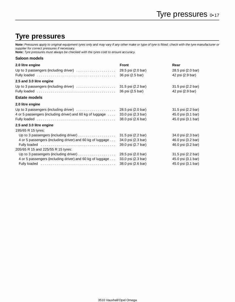
Tyre pressuresNote: Pressures apply to original-equipment tyres only and may vary if any other make or type of tyre is fitted; check with the tyre manufacturer orsupplier for correct pressures if necessary.Note: Tyre pressures must always be checked with the tyres cold to ensure accuracy.
Saloon models
2.0 litre engine Front RearUp to 3 passengers (including driver) . . . . . . . . . . . . . . . . . . . . 28.5 psi (2.0 bar) 28.5 psi (2.0 bar)Fully loaded . . . . . . . . . . . . . . . . . . . . . . . . . . . . . . . . . . . . . . . . 36 psi (2.5 bar) 42 psi (2.9 bar)
2.5 and 3.0 litre engineUp to 3 passengers (including driver) . . . . . . . . . . . . . . . . . . . . 31.5 psi (2.2 bar) 31.5 psi (2.2 bar)Fully loaded . . . . . . . . . . . . . . . . . . . . . . . . . . . . . . . . . . . . . . . . 36 psi (2.5 bar) 42 psi (2.9 bar)
Estate models
2.0 litre engineUp to 3 passengers (including driver) . . . . . . . . . . . . . . . . . . . . 28.5 psi (2.0 bar) 31.5 psi (2.2 bar)4 or 5 passengers (including driver) and 60 kg of luggage . . . . 33.0 psi (2.3 bar) 45.0 psi (3.1 bar)Fully loaded . . . . . . . . . . . . . . . . . . . . . . . . . . . . . . . . . . . . . . . . 38.0 psi (2.6 bar) 45.0 psi (3.1 bar)
2.5 and 3.0 litre engine195/65 R 15 tyres:
Up to 3 passengers (including driver) . . . . . . . . . . . . . . . . . . . 31.5 psi (2.2 bar) 34.0 psi (2.3 bar)4 or 5 passengers (including driver) and 60 kg of luggage . . . 34.0 psi (2.3 bar) 46.0 psi (3.2 bar)Fully loaded . . . . . . . . . . . . . . . . . . . . . . . . . . . . . . . . . . . . . . 39.0 psi (2.7 bar) 46.0 psi (3.2 bar)
205/65 R 15 and 225/55 R 15 tyres:Up to 3 passengers (including driver) . . . . . . . . . . . . . . . . . . . 28.5 psi (2.0 bar) 31.5 psi (2.2 bar)4 or 5 passengers (including driver) and 60 kg of luggage . . . 33.0 psi (2.3 bar) 45.0 psi (3.1 bar)Fully loaded . . . . . . . . . . . . . . . . . . . . . . . . . . . . . . . . . . . . . . 38.0 psi (2.6 bar) 45.0 psi (3.1 bar)

1•1
1
3510 Vauxhall/Opel Omega
Chapter 1Routine maintenance and servicing
Air filter element - renewal . . . . . . . . . . . . . . . . . . . . . . . . . . . . . . . . . 16Automatic transmission fluid - renewal . . . . . . . . . . . . . . . . . . . . . . . 25Automatic transmission fluid level - check . . . . . . . . . . . . . . . . . . . . 19Auxiliary drivebelt - check and renewal . . . . . . . . . . . . . . . . . . . . . . . 6Bodywork/underbody corrosion protection - check . . . . . . . . . . . . . 8Brake fluid - renewal . . . . . . . . . . . . . . . . . . . . . . . . . . . . . . . . . . . . . 26Coolant - renewal . . . . . . . . . . . . . . . . . . . . . . . . . . . . . . . . . . . . . . . 28Driveshaft gaiter condition - check . . . . . . . . . . . . . . . . . . . . . . . . . . 21Engine oil and filter - renewal . . . . . . . . . . . . . . . . . . . . . . . . . . . . . . 3Exhaust system - check . . . . . . . . . . . . . . . . . . . . . . . . . . . . . . . . . . 15Front and rear disc brakes - pad wear check . . . . . . . . . . . . . . . . . . 5Fuel filter - renewal . . . . . . . . . . . . . . . . . . . . . . . . . . . . . . . . . . . . . . 23General information . . . . . . . . . . . . . . . . . . . . . . . . . . . . . . . . . . . . . . 1Handbrake - shoe condition check . . . . . . . . . . . . . . . . . . . . . . . . . . 20
Handbrake operation - check and adjustment . . . . . . . . . . . . . . . . . 9Headlight and auxiliary driving light beam alignment - check . . . . . . 12Lock and hinge lubrication . . . . . . . . . . . . . . . . . . . . . . . . . . . . . . . . 18Monitoring, lighting and signalling equipment - check . . . . . . . . . . . 4Pollen filter - renewal . . . . . . . . . . . . . . . . . . . . . . . . . . . . . . . . . . . . . 17Regular maintenance . . . . . . . . . . . . . . . . . . . . . . . . . . . . . . . . . . . . . 2Remote control keyfob battery - renewal . . . . . . . . . . . . . . . . . . . . . 27Road test . . . . . . . . . . . . . . . . . . . . . . . . . . . . . . . . . . . . . . . . . . . . . . 13Spark plugs - renewal . . . . . . . . . . . . . . . . . . . . . . . . . . . . . . . . . . . . 22Suspension and steering condition and operation - check . . . . . . . . 10Timing belt - renewal . . . . . . . . . . . . . . . . . . . . . . . . . . . . . . . . . . . . . 24Underbonnet/underbody hose and fluid leak - check . . . . . . . . . . . . 7Wheel alignment - check . . . . . . . . . . . . . . . . . . . . . . . . . . . . . . . . . . 14Wheel bolt torque - check and adjustment . . . . . . . . . . . . . . . . . . . . 11
Contents
Easy, suitable fornovice with littleexperience
Fairly easy, suitablefor beginner withsome experience
Fairly difficult,suitable for competentDIY mechanic
Difficult, suitable forexperienced DIYmechanic
Very difficult,suitable for expert DIYor professional
Degrees of difficulty
54321

Lubricants and fluids . . . . . . . . . . . . . . . . . . . . . . . . . . . . . . . . . . Refer to end of Weekly checks on page 0•16
CapacitiesEngine oil
2.0 litre engine:SOHC engine . . . . . . . . . . . . . . . . . . . . . . . . . . . . . . . . . . . . . . . . . 4.5 litresDOHC engine:
Engines with a one-piece sump . . . . . . . . . . . . . . . . . . . . . . . . . 4.5 litresEngines with a two-piece sump . . . . . . . . . . . . . . . . . . . . . . . . . 5.0 litres
2.5 and 3.0 litre engine . . . . . . . . . . . . . . . . . . . . . . . . . . . . . . . . . . . . 5.75 litresDifference between MIN and MAX on dipstick (all engines) . . . . . . . . . . 1.0 litre
Cooling system Manual transmission Automatic transmission2.0 litre engine:
SOHC engine . . . . . . . . . . . . . . . . . . . . . . . . . . . . . . . . . . . . . . . . . . . 9.0 litres 8.8 litresDOHC engine . . . . . . . . . . . . . . . . . . . . . . . . . . . . . . . . . . . . . . . . . . . 8.8 litres 8.6 litres
2.5 and 3.0 litre engine . . . . . . . . . . . . . . . . . . . . . . . . . . . . . . . . . . . . . . 9.7 litres 9.5 litres
TransmissionManual transmission (approximate) . . . . . . . . . . . . . . . . . . . . . . . . . . . . 1.2 litresAutomatic transmission (approximate):
From dry . . . . . . . . . . . . . . . . . . . . . . . . . . . . . . . . . . . . . . . . . . . . . . . 8.4 litresAfter removing main sump . . . . . . . . . . . . . . . . . . . . . . . . . . . . . . . . . 4.4 litres
Final drive . . . . . . . . . . . . . . . . . . . . . . . . . . . . . . . . . . . . . . . . . . . . . . . . 1.0 litre**On models with limited-slip differential, observe the notes in Chapter 8 regarding the correct mixture of oil and additive to be used when refillingthe final drive unit.
Washer fluid reservoirWithout headlight washers . . . . . . . . . . . . . . . . . . . . . . . . . . . . . . . . . . . 3.0 litresWith headlight washers . . . . . . . . . . . . . . . . . . . . . . . . . . . . . . . . . . . . . 6.4 litres
Fuel tankAll models . . . . . . . . . . . . . . . . . . . . . . . . . . . . . . . . . . . . . . . . . . . . . . . . 75 litres
EngineOil filter . . . . . . . . . . . . . . . . . . . . . . . . . . . . . . . . . . . . . . . . . . . . . . . . . . Champion G102
Cooling systemAntifreeze mixture:
50% antifreeze . . . . . . . . . . . . . . . . . . . . . . . . . . . . . . . . . . . . . . . . . . Protection down to -37ºC55% antifreeze . . . . . . . . . . . . . . . . . . . . . . . . . . . . . . . . . . . . . . . . . . Protection down to -45ºC
Note: Refer to antifreeze manufacturer for latest recommendations.
Fuel systemAir filter element:
2.0 litre engine . . . . . . . . . . . . . . . . . . . . . . . . . . . . . . . . . . . . . . . . . . Champion U5952.5 and 3.0 litre engine . . . . . . . . . . . . . . . . . . . . . . . . . . . . . . . . . . . . Champion U601
Fuel filter . . . . . . . . . . . . . . . . . . . . . . . . . . . . . . . . . . . . . . . . . . . . . . . . . Champion L225
Ignition systemSpark plugs (gap not adjustable - see text) . . . . . . . . . . . . . . . . . . . . . . Champion RC10DMC
BrakesFriction material minimum thickness:
Front brake pads . . . . . . . . . . . . . . . . . . . . . . . . . . . . . . . . . . . . . . . . . 8.0 mm including backing plateRear brake pads . . . . . . . . . . . . . . . . . . . . . . . . . . . . . . . . . . . . . . . . . 6.0 mm including backing plateHandbrake shoes . . . . . . . . . . . . . . . . . . . . . . . . . . . . . . . . . . . . . . . . 1.0 mm excluding backing plate
Torque wrench settings Nm lbf ftAutomatic transmission fluid level plug . . . . . . . . . . . . . . . . . . . . . . . . . 33 24Oil filter . . . . . . . . . . . . . . . . . . . . . . . . . . . . . . . . . . . . . . . . . . . . . . . . . . 15 11Roadwheel bolts . . . . . . . . . . . . . . . . . . . . . . . . . . . . . . . . . . . . . . . . . . . 110 81Spark plugs . . . . . . . . . . . . . . . . . . . . . . . . . . . . . . . . . . . . . . . . . . . . . . . 25 18Sump drain plug:
2.0 litre SOHC engine . . . . . . . . . . . . . . . . . . . . . . . . . . . . . . . . . . . . . 55 412.0 litre DOHC engine:
Hex-head bolt . . . . . . . . . . . . . . . . . . . . . . . . . . . . . . . . . . . . . . . . . 45 33Torx-head bolt . . . . . . . . . . . . . . . . . . . . . . . . . . . . . . . . . . . . . . . . . 10 7
2.5 and 3.0 litre engine:Hex-head bolt . . . . . . . . . . . . . . . . . . . . . . . . . . . . . . . . . . . . . . . . . 55 41Torx-head bolt . . . . . . . . . . . . . . . . . . . . . . . . . . . . . . . . . . . . . . . . . 10 7
1•2 Servicing specifications
3510 Vauxhall/Opel Omega

The maintenance intervals in this manualare provided with the assumption that you,not the dealer, will be carrying out the work.These are the minimum maintenance intervalsrecommended by us for vehicles driven daily.If you wish to keep your vehicle in peakcondition at all times, you may wish to
perform some of these procedures moreoften. We encourage frequent maintenance,because it enhances the efficiency,performance and resale value of your vehicle.
If the vehicle is driven in dusty areas, usedto tow a trailer, or driven frequently at slowspeeds (idling in traffic) or on short journeys,
more frequent maintenance intervals arerecommended.
When the vehicle is new, and/or still withinits warranty period, it should be serviced by afactory-authorised dealer service department,in order to preserve the factory warranty.
Maintenance schedule 1•3
1
3510 Vauxhall/Opel Omega
Every 5000 miles (7500 km) or 6 months, whichever comes firstmm Engine oil and filter - renewal (Section 3)Note: Vauxhall recommend that the engine oil and filter are changedevery 10 000 miles or 12 months. However, oil and filter changes aregood for the engine and we recommend that the oil and filter arerenewed more frequently, especially if the vehicle is used on a lot ofshort journeys.
Every 40 000 miles (60 000 km) or 4 years, whichever comes firstCarry out all the operations listed for the 15,000 km/12 month and the30,000 km/2 year intervals, plus the following additional operations:mm Spark plugs - renewal (Section 22)*mm Fuel filter - renewal (Section 23)mm Timing belt - renewal (Section 24)**
* Note: On pre-1999 model year vehicles, renew the spark plugsevery 40 000 miles (60 000 km) regardless of the time elapsed.
**Note: Since the introduction of the Omega in 1994, Vauxhall havegradually increased the specified interval for timing belt renewal asfollows:
1994 model year vehicle,36 000 miles or 4 years, whichever comes first.
1995 and 1996 model year vehicles,40 000 miles or 4 years, whichever comes first.
1997 model year vehicles onwards,80 000 miles or 8 years, whichever comes first.
However, if the vehicle is used mainly for short journeys or a lot ofstop-start driving, or if the vehicle’s history is unknown, it isrecommended that the earlier (1994 model year) recommendation isadhered to. The actual belt renewal interval is very much up to theindividual owner but, bearing in mind that severe engine damage willresult if the belt breaks in use, we recommend you err on the side ofcaution.
Every 10 000 miles (15 000 km) or12 months, whichever comes firstmm Monitoring, lighting and signalling equipment -
check (Section 4)mm Front and rear brakes - pad and disc wear check
(Section 5)mm Auxiliary drivebelt condition and tension - check
and adjust (Section 6)*mm Underbonnet/underbody hose and fluid leak -
check (Section 7)* mm Bodywork/underbody corrosion protection - check
(Section 8)*mm Handbrake operation - check and adjustment
(Section 9)*mm Suspension and steering condition and operation -
check (Section 10)*mm Wheel bolt torque - check and adjustment
(Section 11)mm Headlight and auxiliary driving light beam
alignment - check (Section 12)*mm Road test (Section 13)mm Wheel alignment - check (Section 14)mm Exhaust system - check (Section 15)** Note: On vehicles covering a high mileage (more than 20 000miles/30 000 km annually) carry out the items marked with an asteriskat the 12 month interval; carry out the items not marked with anasterisk every 10 000 miles/15 000 km, regardless of elapsed time.
Every 70 000 miles (105 000 km) or7 years whichever comes firstmm Automatic transmission fluid - renewal (Section 25)*Note: This operation applies only to vehicles covering a high mileage(more than 20 000 miles/30 000 km annually)
Every 20 000 miles (30 000 km) or 2 years, whichever comes firstCarry out all the operations listed for the 15,000 km/12 monthinterval, plus the following additional operations:mm Air filter element - renewal (Section 16)mm Pollen filter - renewal (Section 17)mm Lock and hinge lubrication (Section 18)mm Automatic transmission fluid level check (Section 19)mm Handbrake - shoe condition check (Section 20)mm Driveshaft gaiter condition - check (Section 21)
Every 2 years, regardless of mileagemm Brake fluid - renewal (Section 26)mm Remote control keyfob battery - renewal
(Section 27)mm Coolant - renewal (Section 28)
1•4 Maintenance - component location
3510 Vauxhall/Opel Omega
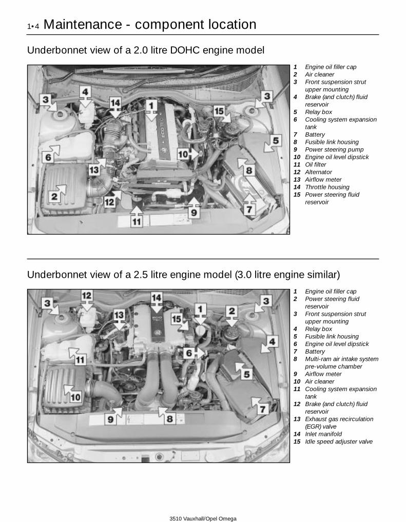
Underbonnet view of a 2.0 litre DOHC engine model
1 Engine oil filler cap2 Air cleaner3 Front suspension strut
upper mounting4 Brake (and clutch) fluid
reservoir5 Relay box6 Cooling system expansion
tank7 Battery8 Fusible link housing9 Power steering pump10 Engine oil level dipstick11 Oil filter12 Alternator13 Airflow meter14 Throttle housing15 Power steering fluid
reservoir
Underbonnet view of a 2.5 litre engine model (3.0 litre engine similar)
1 Engine oil filler cap2 Power steering fluid
reservoir3 Front suspension strut
upper mounting4 Relay box5 Fusible link housing6 Engine oil level dipstick7 Battery8 Multi-ram air intake system
pre-volume chamber9 Airflow meter10 Air cleaner11 Cooling system expansion
tank12 Brake (and clutch) fluid
reservoir13 Exhaust gas recirculation
(EGR) valve14 Inlet manifold15 Idle speed adjuster valve
Maintenance - component location 1•5
1
3510 Vauxhall/Opel Omega
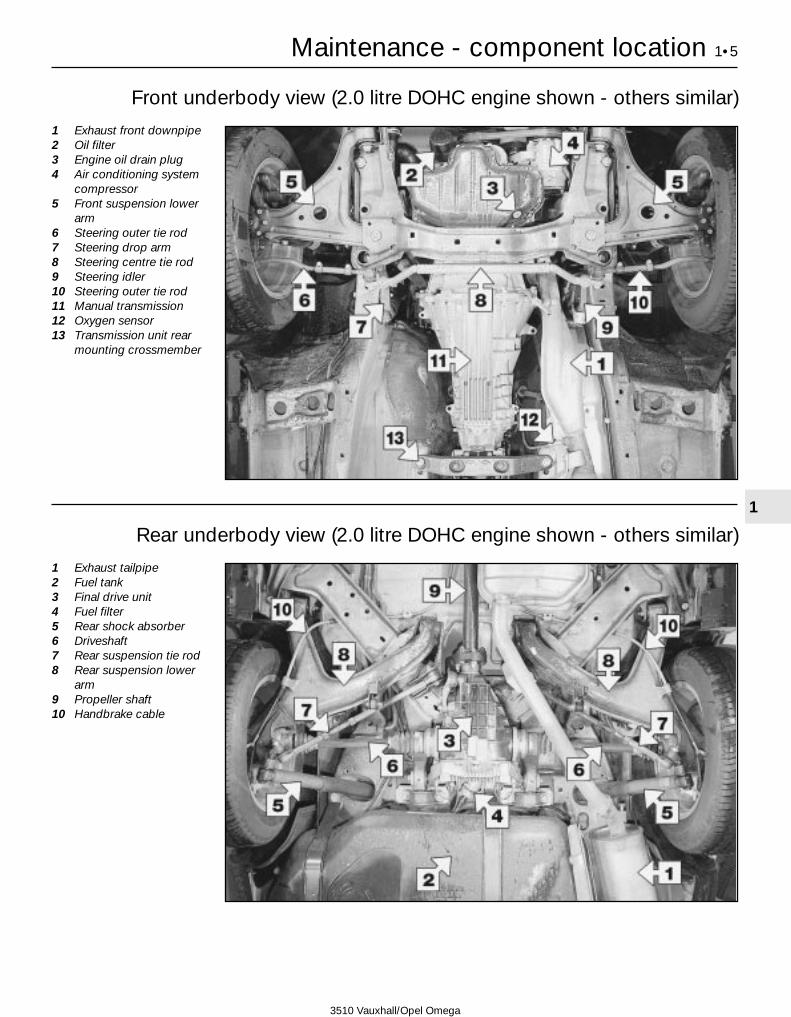
Front underbody view (2.0 litre DOHC engine shown - others similar)
1 Exhaust front downpipe2 Oil filter3 Engine oil drain plug4 Air conditioning system
compressor5 Front suspension lower
arm6 Steering outer tie rod7 Steering drop arm8 Steering centre tie rod9 Steering idler10 Steering outer tie rod11 Manual transmission12 Oxygen sensor13 Transmission unit rear
mounting crossmember
Rear underbody view (2.0 litre DOHC engine shown - others similar)
1 Exhaust tailpipe2 Fuel tank3 Final drive unit4 Fuel filter5 Rear shock absorber6 Driveshaft7 Rear suspension tie rod8 Rear suspension lower
arm9 Propeller shaft10 Handbrake cable

1 General information
1 This Chapter is designed to help the homemechanic maintain his/her vehicle for safety,economy, long life and peak performance.2 The Chapter contains a mastermaintenance schedule, followed by Sectionsdealing specifically with each task in theschedule. Visual checks, adjustments,component renewal and other helpful itemsare included. Refer to the accompanyingillustrations of the engine compartment andthe underside of the vehicle for the locationsof the various components.3 Servicing your vehicle in accordance with themileage/time maintenance schedule and thefollowing Sections will provide a plannedmaintenance programme, which should resultin a long and reliable service life. This is acomprehensive plan, so maintaining someitems but not others at the specified serviceintervals, will not produce the same results.4 As you service your vehicle, you willdiscover that many of the procedures can -and should - be grouped together, because ofthe particular procedure being performed, orbecause of the proximity of two otherwise-unrelated components to one another. Forexample, if the vehicle is raised for any reason,the exhaust can be inspected at the same timeas the suspension and steering components.5 The first step in this maintenance pro-
gramme is to prepare yourself before the actualwork begins. Read through all the Sectionsrelevant to the work to be carried out, thenmake a list and gather all the parts and toolsrequired. If a problem is encountered, seekadvice from a parts specialist, or a dealerservice department.
2 Regular maintenance
1 If, from the time the vehicle is new, theroutine maintenance schedule is followedclosely, and frequent checks are made of fluidlevels and high-wear items, as suggestedthroughout this manual, the engine will bekept in relatively good running condition, andthe need for additional work will be minimised.2 It is possible that there will be times whenthe engine is running poorly due to the lack ofregular maintenance. This is even more likelyif a used vehicle, which has not receivedregular and frequent maintenance checks, ispurchased. In such cases, additional workmay need to be carried out, outside of theregular maintenance intervals.3 If engine wear is suspected, a compressiontest (refer to Chapter 2A, 2B or 2C, asapplicable) will provide valuable informationregarding the overall performance of the maininternal components. Such a test can be usedas a basis to decide on the extent of the workto be carried out. If, for example, a
compression test indicates serious internalengine wear, conventional maintenance asdescribed in this Chapter will not greatlyimprove the performance of the engine, andmay prove a waste of time and money, unlessextensive overhaul work is carried out first.4 The following series of operations are thosemost often required to improve the perfor-mance of a generally poor-running engine:
Primary operationsa) Clean, inspect and test the battery (refer
to Weekly checks).b) Check all the engine-related fluids (refer
to Weekly checks).c) Check the condition and tension of the
auxiliary drivebelt (Section 6).d) Renew the spark plugs (Section 22).e) Check the condition of the air filter, and
renew if necessary (Section 16).f) Renew the fuel filter (Section 23).g) Check the condition of all hoses, and
check for fluid leak.5 If the above operations do not prove fullyeffective, carry out the following secondaryoperations:
Secondary operationsAll items listed under Primary operations, plusthe following:a) Check the charging system (refer to
Chapter 5A). b) Check the ignition system (refer to
Chapter 5B).c) Check the fuel system (refer to Chapter 4A).
3 Engine oil and filter - renewal 2
1 Frequent oil and filter changes are the mostimportant preventative maintenanceprocedures which can be undertaken by theDIY owner. As engine oil ages, it becomesdiluted and contaminated, which leads topremature engine wear.2 Before starting this procedure, gathertogether all the necessary tools and materials.
Also make sure that you have plenty of cleanrags and newspapers handy, to mop up anyspills. Ideally, the engine oil should be warm,as it will drain more easily, and more built-upsludge will be removed with it. Take care notto touch the exhaust or any other hot parts ofthe engine when working under the vehicle.To avoid any possibility of scalding, and toprotect yourself from possible skin irritantsand other harmful contaminants in usedengine oils, it is advisable to wear gloveswhen carrying out this work.3 Firmly apply the handbrake then jack up thefront of the vehicle and support it on axlestands (see Jacking and Vehicle Support).Undo the retaining screws and remove theundercover from beneath the engine unit.4 Remove the oil filler cap.5 Using a spanner, or preferably a suitablesocket and bar, slacken the drain plug abouthalf a turn (see illustration). Position thedraining container under the drain plug, thenremove the plug completely (see HaynesHint).6 Allow some time for the oil to drain, notingthat it may be necessary to reposition thecontainer as the oil flow slows to a trickle.7 After all the oil has drained, wipe the drainplug and the sealing washer with a clean rag.
Examine the condition of the sealing washer,and renew it if it shows signs of scoring orother damage which may prevent an oil-tightseal. Clean the area around the drain plugopening, and refit the plug complete with thewasher and tighten it to the specified torque.8 Move the container into position under theoil filter. On 2.0 litre engines the filter islocated on the front end of the engine, where
1•6 Maintenance procedures
3.5 Removing the sump drain plug
3510 Vauxhall/Opel Omega
Every 5000 miles or 6 months
As the drain plug releases from thethreads, move it quickly away so thatthe stream of oil running out of thesump goes into the container and notover your arm

it is screwed onto the oil pump housing, andon 2.5 and 3.0 litre engines it is screwed ontothe left-hand side of the cylinder block (seeillustration).9 Use an oil filter removal tool to slacken thefilter initially, then unscrew it by hand the restof the way. Empty the oil from the old filterinto the container.10 Use a clean rag to remove all oil, dirt andsludge from the filter sealing area on theengine.11 Apply a light coating of clean engine oilto the sealing ring on the new filter, thenscrew the filter into position on the engine.Tighten the filter firmly by hand only - do notuse any tools (see illustrations). If a genuinefilter is being fitted and the special oil filter
tool (Tool no. KM-726A - a socket which fitsover the end of the filter) is available, tightenthe filter to the specified torque.12 Refit the undercover, tightening itsretaining screws securely, then remove theold oil and all tools from under the vehiclebefore lowering the vehicle to the ground.13 Fill the engine through the filler hole, usingthe correct grade and type of oil (refer toWeekly Checks for details of topping-up).Pour in half the specified quantity of oil first,then wait a few minutes for the oil to drain intothe sump. Continue to add oil, a smallquantity at a time, until the level is up to thelower mark on the dipstick. Addingapproximately a further 1.0 litre will bring thelevel up to the upper mark on the dipstick.
14 Start the engine and run it for a fewminutes, while checking for leaks around theoil filter seal and the sump drain plug. Notethat there may be a delay of a few secondsbefore the low oil pressure warning light goesout when the engine is first started, as the oilcirculates through the new oil filter and theengine oil galleries before the pressure buildsup.15 Stop the engine, and wait a few minutesfor the oil to settle in the sump once more.With the new oil circulated and the filter nowcompletely full, recheck the level on thedipstick, and add more oil as necessary.16 Dispose of the used engine oil safely withreference to General repair procedures.
Every 5000 miles 1•7
1
3.8 Oil filter location - 2.0 litre engine 3.11a Lubricate the sealing ring of the newfilter with a smear of engine oil . . .
3.11b . . . then screw the filter on by handonly (2.5 litre engine shown)
3510 Vauxhall/Opel Omega
4 Monitoring, lighting andsignalling equipment - check
11 Turn the ignition switch to the secondposition and check that the instrument panelCHECK lamp lights up and then extinguishesafter 4 approximately seconds. If the lampfails to extinguish, observe the faultdescription message(s) displayed and rectifythe cause.2 Start the engine and check that all tell-talesystem operation/fault lamps extinguish. Notethat some lamps (such as the automatictransmission sport programme, or tractioncontrol system lamps) may remain lit,depending on the driving mode selected;consult your drivers handbook for the exactmeaning of each lamp.3 Release handbrake, depress the brakepedal and check that the brake lights faultdisplay extinguishes. 4 Switch on all interior and exterior lights inturn and check their operation. Pay particularattention to the tail lamps, fog lamps, brakelamps, main and dipped beam headlamps,position lamps and front and rear directionindicators. Renew any blown bulbs withreference to Chapter 12.5 Finally, check the operation of the horn.
5 Front and rear brakes - pad and disc wear check 2
Front brakes1 Firmly apply the handbrake, select first gearor P, then jack up the front of the vehicle andsupport it securely on axle stands (seeJacking and Vehicle Support). Remove thefront roadwheels.2 For a quick check, the pad thickness can
be carried out via the inspection hole on thefront surface of each caliper (see illustration).Using a steel rule, measure the thickness ofeach pad lining, including the backing plate.This must not be less than that indicated inthe Specifications.3 The view through the caliper inspectionhole gives only a rough indication of thestate of the brake pads. For a comprehensivecheck, the brake pads should be removedand cleaned. The operation of the caliper canthen also be checked, and the condition of thebrake disc itself can be fully examined on bothsides. Chapter 9 contains a detaileddescription of how the brake discs should bechecked for wear and/or damage.4 If any pad’s friction material is worn to thespecified thickness or less, all four pads mustbe renewed as an axle set; for example - if thepads in the left hand caliper are found to beworn, those in the right hand caliper must alsobe renewed, regardless of their condition.Refer to Chapter 9 for details.5 On completion, refit the roadwheels andlower the vehicle to the ground.
Rear brakes6 Chock the front wheels, then jack up therear of the vehicle and support it securely onaxle stands (see Jacking and VehicleSupport). Remove the rear roadwheels.
Every 10 000 miles or 12 months
5.2 The brake pad wear can be assessedby observing the thickness of the frictionmaterial, visible through the inspection
aperture at the front of the brake caliper

7 Proceed as described in paragraphs 2 to 4inclusive, noting that the inspection apertureis at the rear of the caliper.8 On completion, refit the rear roadwheelsand lower the vehicle to the ground.
6 Auxiliary drivebelt - check and renewal 3
Check1 Although the drivebelt tension isautomatically adjusted by the spring-loadedtensioner, the belt itself should still beregularly checked for damage or deterioration.2 With the engine stopped, inspect the fulllength of the drivebelt for cracks andseparation of the belt plies. It will benecessary to turn the engine (using a spanneror socket and bar on the crankshaft pulleybolt) in order to move the belt from the pulleysso that the belt can be inspected thoroughly.Twist the belt between the pulleys so thatboth sides can be viewed. Also check forfraying, and glazing which gives the belt a
shiny appearance. Check the pulleys fornicks, cracks, distortion and corrosion.3 Check the position of the drivebelttensioner assembly arm in relation to thebackplate. On 2.0 litre engines the armindicator should be in between the stops onthe backplate and should be free to move. On2.5 and 3.0 litre engines the stop on thetensioner mounting plate should bepositioned between the lugs on the arm andthe arm should be free to move (seeillustrations).4 If the belt shows signs of wear or damage,or the tensioner arm is against the stop, thebelt must be renewed.
Renewal
2.0 litre engine5 Prior to removal make a note of the correctrouting of the belt around the various pulleys.If the belt is to be reused, also mark thedirection of rotation on the belt to ensure thebelt is refitted the same way around.6 Using a suitable spanner or socket fitted tothe tensioner pulley centre bolt, lever thetensioner away from the belt until there issufficient slack to enable the belt to beslipped off from the pulleys. Carefully releasethe tensioner pulley until it is against its stopthen remove the belt from the vehicle. Ifnecessary, the tensioner can be locked in thereleased position by aligning the arm hole withthe hole in the backplate and inserting asuitable tool/pin.7 Manoeuvre the belt into position, routing itcorrectly around the pulleys; if the original beltis being fitted use the marks made prior toremoval to ensure it is fitted the correct wayaround.8 Lever the tensioner roller back against isspring, and seat the belt on the pulleys.Ensure the belt is centrally located on allpulleys then slowly release the tensioner
pulley until the belt is correctly tensioned. Donot allow the tensioner to spring back andstress the belt.9 Check the tensioner arm is correctlypositioned in relation to the backplate (seeparagraph 3).
2.5 and 3.0 litre engine10 Remove the multi-ram air intake systempre-volume chamber and the secondary airinjection system front connecting pipe asdescribed in the relevant Parts of Chapter 4.11 Prior to removal make a note of thecorrect routing of the belt around the variouspulleys. If the belt is to be reused, also markthe direction of rotation on the belt to ensurethe belt is refitted the same way around.12 Using a suitable spanner or socket fittedto the tensioner pulley centre bolt, lever thetensioner away from the belt until there issufficient slack to enable the belt to beslipped off from the pulleys (see illustration).Carefully release the tensioner pulley until it isagainst its stop then remove the belt from thevehicle.13 Manoeuvre the belt into position, routing itcorrectly around the pulleys; if the original beltis being fitted use the marks made prior toremoval to ensure it is fitted the correct wayaround.14 Lever the tensioner roller back against isspring, and seat the belt on the pulleys.Ensure the belt is centrally located on allpulleys then slowly release the tensionerpulley until the belt is correctly tensioned. Donot allow the tensioner to spring back andstress the belt.15 Check the tensioner arm is correctlypositioned in relation to the backplate (seeparagraph 3) then refit the secondary airinjection system connecting pipe and themulti-ram air intake system pre-volumechamber as described in the relevant part ofChapter 4.
1•8 Every 10 000 miles
6.12 Lever the tensioner away from thebelt then slip the belt off from its pulleys
(2.5 litre engine shown)
3510 Vauxhall/Opel Omega
6.3a On 2.0 litre engines check that the drivebelt tensioner armindicator (2) is correctly positioned between the stops (1 and 3) on
the backplate
6.3b On 2.5 and 3.0 litre engines ensure the stop (1) on thedrivebelt tensioner mounting plate is in between the lugs (2) on
the arm

7 Underbonnet/underbodyhose and fluid leak - check
2Cooling system
Warning: Refer to the safetyinformation given in Safety Firstand Chapter 3 before disturbing
any of the cooling system components.1 Carefully check the radiator and heatercoolant hoses along their entire length. Renewany hose which is cracked, swollen or whichshows signs of deterioration. Cracks will showup better if the hose is squeezed. Pay closeattention to the clips that secure the hoses tothe cooling system components. Hose clipsthat have been over-tightened can pinch andpuncture hoses, resulting in cooling systemleaks (see illustration).2 Inspect all the cooling system components(hoses, joint faces, etc) for leaks. Where anyproblems of this nature are found on systemcomponents, renew the component or gasketwith reference to Chapter 3.
Fuel systemWarning: Refer to the safetyinformation given in Safety Firstand Chapter 4A before disturbing
any of the fuel system components.3 Petrol leaks can be difficult to pinpoint,unless the leakage is significant and henceeasily visible. Fuel tends to evaporate quicklyonce it comes into contact with air, especiallyin a hot engine bay. Small drips can disappearbefore you get a chance to identify the pointof leakage. If you suspect that there is a fuelleak from the area of the engine bay, leave thevehicle overnight then start the engine fromcold, with the bonnet open. Metalcomponents tend to shrink when they arecold, and rubber seals and hoses tend toharden, so any leaks will be more apparentwhilst the engine is warming up from a coldstart.4 Check all fuel lines at their connections tothe fuel rail, fuel pressure regulator and fuelfilter (petrol models), Examine each rubberfuel hose along its length for splits or cracks.Check for leakage from the crimped jointsbetween rubber and metal fuel lines. Examinethe unions between the metal fuel lines andthe fuel filter housing. Also check the areaaround the fuel injectors for signs of O-ringleakage.5 To identify fuel leaks between the fuel tankand the engine bay, the vehicle should raisedand securely supported on axle stands.
Inspect the petrol tank and filler neck forpunctures, cracks and other damage. Theconnection between the filler neck and tank isespecially critical. Sometimes a rubber fillerneck or connecting hose will leak due to looseretaining clamps or deteriorated rubber.6 Carefully check all rubber hoses and metalfuel lines leading away from the petrol tank.Check for loose connections, deterioratedhoses, kinked lines, and other damage. Payparticular attention to the vent pipes andhoses, which often loop up around the fillerneck and can become blocked or kinked,making tank filling difficult. Follow the fuelsupply and return lines to the front of thevehicle, carefully inspecting them all the wayfor signs of damage or corrosion. Renewdamaged sections as necessary.
Engine oil7 Inspect the area around the camshaftcover, cylinder head, oil filter and sump jointfaces. Bear in mind that, over a period of time,some very slight seepage from these areas isto be expected - what you are really lookingfor is any indication of a serious leak causedby gasket failure. Engine oil seeping from thebase of the timing belt cover or thetransmission bellhousing may be an indicationof crankshaft or transmission input shaft oilseal failure. Should a leak be found, renew thefailed gasket or oil seal by referring to theappropriate Chapters in this manual.
Automatic transmission fluid8 Check the hoses leading to thetransmission fluid cooler for leakage. Look fordeterioration caused by corrosion anddamage from grounding, or debris thrown upfrom the road surface. Automatic transmissionfluid is a thin oil and is usually red in colour.Check the area around the propeller shaft sealat the rear of the transmission for signs of fluidleakage. Should a leak be found, check thefluid level as described in Section 19 thenrectify the cause of leakage as soon aspossible.
Power assisted steering (PAS)fluid9 Examine the hose running between the fluidreservoir and the power steering pump, andthe return hose running from the steering rackto the fluid reservoir. Also examine the highpressure supply hose between the pump andthe steering rack.10 Check the condition of each hosecarefully. Look for deterioration caused bycorrosion and damage from grounding, ordebris thrown up from the road surface.11 Pay particular attention to crimpedunions, and the area surrounding the hosesthat are secured with adjustable worm driveclips. Like automatic transmission fluid, PASfluid is a thin oil, and is usually red or lightbrown in colour.
Every 10 000 miles 1•9
1
3510 Vauxhall/Opel Omega
7.1 Possible causes of coolant hose failure
A leak in the cooling systemwill usually manifest itself aswhite or rust-coloured,crusty deposits on the area
adjacent to the leak

Air conditioning refrigerantWarning: Refer to the safetyinformation given in Safety Firstand Chapter 3, regarding the
dangers of disturbing any of the airconditioning system components.12 The air conditioning system is filled with aliquid refrigerant, which is retained under highpressure. If the air conditioning system isopened and depressurised without the aid ofspecialised equipment, the refrigerant willimmediately turn into gas and escape into theatmosphere. If the liquid comes into contactwith your skin, it can cause severe frostbite. Inaddition, the refrigerant contains substanceswhich are environmentally damaging; for thisreason, it should not be allowed to escapeinto the atmosphere in an uncontrolledfashion.13 Any suspected air conditioning systemleaks should be immediately referred to aVauxhall dealer or air conditioning specialist.Leakage will be shown up as a steady drop inthe level of refrigerant in the system.14 Note that water may drip from thecondenser drain pipe, underneath the car,immediately after the air conditioning systemhas been in use. This is normal, and shouldnot be cause for concern.
Brake fluidWarning: Refer to the safetyinformation given in Safety Firstand Chapter 9, regarding the
dangers of handling brake fluid.15 Examine the area surrounding the brakepipe unions at the master cylinder for signs ofleakage. Check the area around the base offluid reservoir, for signs of leakage caused byseal failure. Also examine the brake pipeunions at the ABS hydraulic unit.16 If fluid loss is evident, but the leak cannotbe pinpointed in the engine bay, the brakecalipers and underbody brake lines should becarefully checked with the vehicle raised andsupported on axle stands (see illustration).Leakage of fluid from the braking system is aserious fault that must be rectifiedimmediately.17 Brake/clutch hydraulic fluid is a toxicsubstance with a watery consistency. Newfluid is almost colourless, but it becomesdarker with age and use.
Manual transmission fluid18 Check the area around the propeller shaftseal at the rear of the transmission for signs offluid leakage. Should a leak be found, checkthe transmission fluid level as described inChapter 7A then rectify the cause of leakageas soon as possible.
Final drive unit differential fluid 19 Check the area around the driveshaft andpropeller shaft seals, and the flange seal onthe rear of the final drive unit for signs of fluid
leakage. Should a leak be found, check thedifferential fluid level as described in Chapter 8then rectify the cause of leakage as soon aspossible.
Unidentified fluid leaks20 If there are signs that a fluid of somedescription is leaking from the vehicle, butyou cannot identify the type of fluid or itsexact origin, park the vehicle overnight andslide a large piece of card underneath it.Providing that the card is positioned inroughly the right location, even the smallestleak will show up on the card. Not only willthis help you to pinpoint the exact location ofthe leak, it should be easier to identify the fluidfrom its colour. Bear in mind, though, that theleak may only be occurring when the engine isrunning!
Vacuum hoses21 Although the braking system ishydraulically-operated, the brake servo unitamplifies the effort applied at the brake pedal,by making use of the vacuum in the inletmanifold, generated by the engine. Vacuum isported to the servo by means of a large-borehose. Any leaks that develop in this hose willreduce the effectiveness of the brakingsystem, and may affect the running of theengine.22 In addition, a number of the underbonnetcomponents, particularly the emission controlcomponents, are driven by vacuum suppliedfrom the inlet manifold via narrow-bore rubber
and plastic hoses. A leak in a vacuum hosemeans that air is being drawn into the hose(rather than escaping from it) and this makesleakage very difficult to detect. One method isto use an old length of vacuum hose as a kindof stethoscope - hold one end close to (butnot in!) your ear and use the other end toprobe the area around the suspected leak.When the end of the hose is directly over avacuum leak, a hissing sound will be heardclearly through the hose. Care must be takento avoid contacting hot or movingcomponents, as the engine must be running,when testing in this manner. Renew anyvacuum hoses that are found to be defective.
8 Bodywork/underbodycorrosion protection - check
51 This work should be carried out by aVauxhall/Opel dealer in order to validate thevehicle warranty. The work includes athorough inspection of the vehicle paintworkand underbody for damage and corrosion
9 Handbrake operation - check and adjustment 2
1 Chock the front wheels, then jack up therear of the vehicle and support it securely onaxle stands (see Jacking and VehicleSupport). Remove the rear roadwheels.2 Fully release the handbrake lever, thenapply it to the third notch. Check that bothrear wheels can still rotate by attempting toturn them by hand (ensure that thetransmission is in neutral). Release thehandbrake lever.3 Fully apply the handbrake lever, so that therear wheels are locked, counting how manynotches the lever passes through. If thehandbrake lever passes through more thanseven notches before the rear wheels lock,adjustment is required.4 If adjustment is necessary, first fully releasethe handbrake, then pull it up to the thirdnotch.5 Working underneath the vehicle, unbolt theexhaust system heat shields from thefloorpan. Locate the handbrake cableadjustment nut, at the cable compensationbar, above the propeller shaft. Fully slackenthe adjustment nut so that there is a smallamount of clearance between it and thecompensation bar (see illustration).6 Working on one brake disc at a time,position the hole in the disc over the serratedadjustment nut on the adjuster at the top ofthe backplate. Using a screwdriver insertedthrough the hole, turn the nut until the brakedisc locks, then turn the nut in oppositedirection until the disc is just free (seeillustration). Repeat the adjustment on theremaining rear brake.
1•10 Every 10 000 miles
7.16 Inspecting the flexible hoseconnection to a front brake caliper
9.5 Handbrake cable adjustment nut(arrowed)
3510 Vauxhall/Opel Omega

7 Check that the handbrake lever is stillpositioned on the third notch, then workingunderneath the vehicle, tighten the handbrakecable adjustment nut against thecompensation bar, until the handbrake shoesjust start to take effect - test for this by turningthe brake discs by hand.8 Refit the rear wheels, then carry out a finalcheck of the handbrake adjustment; the rearwheels should turn freely with the leverapplied to the third notch and should be fullylocked before passing through the seventhnotch. Tighten the wheel bolts to the specifiedtorque then lower the car the ground. Checkthe operation of the handbrake before usingthe vehicle on the road.9 After fitting new handbrake shoes, theshoes should be bedded-in by driving a shortdistance (approximately 300 metres) at lowspeed with the handbrake lever lightlyapplied. Check, and if necessary adjust thehandbrake again after completing thebedding-in.
10 Suspension and steeringcondition and operation -check
2Front suspension and steeringcheck1 Raise the front of the vehicle, and securelysupport it on axle stands (see Jacking andVehicle Support).2 Visually inspect the balljoint dust coversand the steering rack-and-pinion gaiters forsplits, chafing or deterioration. Any wear ofthese components will cause loss of lubricant,together with dirt and water entry, resulting inrapid deterioration of the balljoints or steeringgear.3 Check the power steering fluid hoses forchafing or deterioration, and the pipe andhose unions for fluid leaks. Also check forsigns of fluid leakage under pressure from thesteering gear rubber gaiters, which wouldindicate failed fluid seals within the steeringgear.4 Grasp the roadwheel at the 12 o’clock and6 o’clock positions, and try to rock it (seeillustration). Very slight free play may be felt,but if the movement is appreciable, furtherinvestigation is necessary to determine thesource. Continue rocking the wheel while anassistant depresses the footbrake. If themovement is now eliminated or significantlyreduced, it is likely that the hub bearings areat fault. If the free play is still evident with thefootbrake depressed, then there is wear in thesuspension joints or mountings.5 Now grasp the wheel at the 9 o’clock and 3o’clock positions, and try to rock it as before.Any movement felt now may again be causedby wear in the hub bearings or the steeringtrack-rod balljoints. If the outer balljoint isworn, the visual movement will be obvious. Ifthe inner joint is suspect, it can be felt by
placing a hand over the rack-and-pinionrubber gaiter and gripping the track-rod. If thewheel is now rocked, movement will be felt atthe inner joint if wear has taken place.6 Using a large screwdriver or flat bar, checkfor wear in the suspension mounting bushesby levering between the relevant suspensioncomponent and its attachment point. Somemovement is to be expected, as themountings are made of rubber, but excessivewear should be obvious. Also check thecondition of any visible rubber bushes,looking for splits, cracks or contamination ofthe rubber.7 With the car standing on its wheels, have anassistant turn the steering wheel back-and-forth, about an eighth of a turn each way.There should be very little, if any, lostmovement between the steering wheel androadwheels. If this is not the case, closelyobserve the joints and mountings previouslydescribed. In addition, check the steeringcolumn universal joints for wear, and alsocheck the rack-and-pinion steering gear itself.
Rear suspension check8 Chock the front wheels, then jack up therear of the vehicle and support securely onaxle stands (see Jacking and VehicleSupport).9 Working as described previously for thefront suspension, check the rear hubbearings, the suspension bushes and the strutor shock absorber mountings (as applicable)for wear.
Shock absorber check10 Check for any signs of fluid leakagearound the shock absorber body, or from therubber gaiter around the piston rod. Shouldany fluid be noticed, the shock absorber isdefective internally, and should be renewed.Note: Shock absorbers should always berenewed in pairs on the same axle.11 The efficiency of the shock absorber maybe checked by bouncing the vehicle at eachcorner. Generally speaking, the body willreturn to its normal position and stop afterbeing depressed. If it rises and returns on arebound, the shock absorber is probablysuspect. Also examine the shock absorberupper and lower mountings for any signs ofwear.
11 Wheel bolt torque - check and adjustment 2
Note: As well as being potentially damagingto the vehicle’s roadwheels, over-tightenedwheel bolts may cause problems if youhave to change a wheel by the side of theroad. By ensuring that the wheel bolts aretightened to the correct torque, you couldsave yourself a lot of time and trouble in anemergency situation.1 Slacken the front wheel securing boltsslightly, then apply the handbrake firmly, raisethe front of the vehicle, and securely supportit on axle stands (see Jacking and VehicleSupport).2 Fully slacken the each of the wheel bolts inturn and clear any dirt of debris from thethreads. Re-insert the wheel bolts and tightenthem to the specified torque setting using agood quality torque wrench.3 Repeat the operation at the opposite wheel,then lower the car the ground.4 Chock the front wheels, then jack up therear of the vehicle and support securely onaxle stands (see Jacking and VehicleSupport). Repeat the operations described inparagraphs 2 and 3.
12 Headlight and auxiliarydriving light beam alignment- check
51 Badly adjusted headlights and/or foglightscause poor visibility and can dazzle other roadusers. Accurate adjustment of the headlightand auxiliary driving light beams is onlypossible using optical beam-settingequipment, and this work should therefore becarried out by a Vauxhall/Opel dealer orsuitably-equipped workshop. 2 For reference, the headlights can beadjusted using the adjuster assemblies fittedto the front upper outer mounting and to therear inner mounting. The inner screw is forhorizontal adjustment and the outer one for
Every 10 000 miles 1•11
1
9.6 Adjusting the handbrake screws usinga screwdriver through the hole in the
disc/hub flange
10.4 To check for play in the wheel bearing,grasp the roadwheel at the 12 o’clock and
6 o’clock positions, and try to rock it
3510 Vauxhall/Opel Omega

vertical adjustment. When adjusting theheadlight aim, ensure that the facia -mountedrange adjustment switch is set to position 0(see paragraph 3).3 All models have an electric headlight beamadjustment range system, controlled via arotary switch in the facia*. The recommendedsettings are as follows.
0 Front seat(s) occupied1 All seats occupied2 All seats occupied, and load in luggage
compartment3 Driver’s seat occupied and load in the
luggage compartment
*On models built from 1998 onwards withXenon headlights, an automatic headlamprange adjustment system is fitted, to whichno manual adjustment can be made; seeChapter 12 for details.
13 Road test 1Instruments and electrical equipment1 Check the operation of all instruments andelectrical equipment.2 Make sure that all instruments read correctly,and switch on all electrical equipment in turn, tocheck that it functions properly.
Steering and suspension3 Check for any abnormalities in the steering,suspension, handling or road feel.4 Drive the vehicle, and check that there areno unusual vibrations or noises.5 Check that the steering feels positive, withno excessive sloppiness, or roughness, andcheck for any suspension noises whencornering and driving over bumps.
Drivetrain6 Check the performance of the engine,clutch, transmission and driveshafts.
7 Listen for any unusual noises from theengine, clutch and transmission.8 Make sure that the engine runs smoothlywhen idling, and that there is no hesitationwhen accelerating.9 Check that, where applicable, the clutchaction is smooth and progressive, that thedrive is taken up smoothly, and that the pedaltravel is not excessive. Also listen for anynoises when the clutch pedal is depressed.10 Check that all gears can be engagedsmoothly without noise, and that the gearlever action is not abnormally vague ornotchy.11 On automatic transmission models, makesure that all gearchanges occur smoothly,without snatching, and without an increase inengine speed between changes. Check thatall of the gear positions can be selected withthe vehicle at rest. If any problems are found,they should be referred to a Vauxhall/Opeldealer.
Check the operation andperformance of the brakingsystem12 Make sure that the vehicle does not pull toone side when braking, and that the wheelsdo not lock prematurely when braking hard.13 Check that there is no vibration throughthe steering when braking.14 Check that the handbrake operatescorrectly, without excessive movement of thelever, and that it holds the vehicle stationaryon a slope.15 Test the operation of the brake servo unitas follows. Depress the footbrake four or fivetimes to exhaust the vacuum, then start theengine. As the engine starts, there should be anoticeable give in the brake pedal as vacuumbuilds up. Allow the engine to run for at leasttwo minutes, and then switch it off. If thebrake pedal is now depressed again, it shouldbe possible to detect a hiss from the servo asthe pedal is depressed. After about four or fiveapplications, no further hissing should beheard, and the pedal should feel considerablyharder.
14 Wheel alignment - check 5
1 Accurate wheel alignment is essential forpositive, accurate steering, stable roadholding and to prevent abnormal tyre wear.Wheel alignment checking is carried out withthe car loaded to its kerbside weight, and withthe tyre pressures correctly adjusted.2 The front toe setting, front camber angle,rear toe setting and rear camber angle are alladjustable, but can only be checked usingspecialised equipment; work of this natureshould therefore be entrusted to a garage orsuitably-equipped tyre specialist.
15 Exhaust system - check 2
1 Park the vehicle on a level surface andswitch off the engine. Chock the front wheels,then raise the rear of the vehicle and supportit securely on axle stands - refer to Jackingand vehicle support in Reference.2 With the engine cold (wait at least an hourafter switching off the engine), check thecomplete exhaust system from the engine tothe end of the tailpipe.3 Check the exhaust pipes and connectionsfor evidence of leaks, severe corrosion anddamage. Make sure that all brackets andmountings are in good condition, and that allrelevant nuts and bolts are tight. Leakage atany of the joints or in other parts of the systemwill usually show up as a black, sooty stain inthe vicinity of the leak. 4 Rattles and vibrations can often be tracedto the exhaust system. Tap the silencer unitswith a soft mallet and listen for noises causedby corroded or displaced baffle material. Donot strike the catalytic converter, as this maydamage the ceramic block inside.5 Carefully rock the pipes and silencers fromside to side on their mountings. If thecomponents are able to come into contactwith the body or suspension parts, look forbroken or worn rubber mountings.
1•12 Every 10 000 miles
3510 Vauxhall/Opel Omega
16 Air filter element - renewal 1
1 The air cleaner is located in the front right-hand corner of the engine compartment.2 Release the retaining clip and disconnectthe intake duct from the air cleaner housing.3 Release the retaining clips then lift the aircleaner cover and filter element out of position.4 Wipe out the casing and the cover.5 Fit the new filter, noting that the rubberlocating flange should be uppermost, andsecure the cover with the clips.
6 Reconnect the intake duct to the air cleanerhousing and secure it in position with theretaining clip.
17 Pollen filter - renewal 2
1 Open the bonnet and support it in theupright position.2 Carefully peel the rubber beading awayfrom the bulkhead seam, at the rear of theengine compartment, on the drivers side ofthe car (see illustration).
Every 20 000 miles or 2 years
17.2 Carefully peel the rubber beadingaway from the bulkhead seam

3 Hinge the grille panel upwards to exposethe pollen filter housing (see illustration).4 Release the clips at either side of thehousing, then withdraw the pollen filterelement (see illustrations).5 Slide the new filter element into the housingand secure it in position with the clips.6 Hinge the grille panel down over thehousing and press the rubber beading intoposition on the bulkhead seam.
18 Lock and hinge lubrication 11 Work around the vehicle and lubricate thehinges of the bonnet, doors and tailgate/bootlid with a light machine oil.
2 Lightly lubricate the bonnet releasemechanism and exposed section of innercable with a smear of grease.3 Check the security and operation of allhinges, latches and locks, adjusting themwhere required. Check the operation of thecentral locking system.4 Check the condition and operation of thetailgate/boot lid struts, renewing them both ifeither is leaking or no longer able to supportthe tailgate/boot lid securely when raised.
19 Automatic transmission fluid level - check
31 The transmission fluid level must bechecked with the engine warm. For the checkto be accurate, Vauxhall state that thetransmission fluid temperature should ideallybe 60ºC but can be anywhere in the range of45 to 85ºC (113 to 185ºF).2 Take the vehicle on a short run to warm theengine and transmission unit up to operatingtemperature. On your return position thevehicle over an inspection pit, on vehicleramps, or jack it up, but make sure that it islevel.3 Start the engine and allow it to idle. Wipeclean the area around the level plug which isfitted to the right-hand side of thetransmission main sump (see illustration).
Unscrew the plug and clean it.4 The oil level should reach the lower edge ofthe level plug hole. If topping up is necessary,add the specified type of oil through the levelplug hole until oil begins to trickle out.5 Allow the excess oil to drain out then fit anew sealing washer to the level plug and refitit to the sump, tightening it to the specifiedtorque.
20 Handbrake - shoe condition check
1 Refer to the information given in Chapter 9for details.
21 Driveshaft gaiter condition -check 2
1 Chock the front wheels, then jack up the rearof the vehicle and support it on axle stands.2 With the handbrake released turn eachwheel separately and check the driveshaftrubber gaiters for splits and damage. Checkthat the securing clips are in good conditionand shows no signs of damage or corrosion.Driveshaft grease sprayed in a line along theunderside of the car, above the joint is a signthat the gaiter has failed and requires renewal.
Every 20 000 miles 1•13
1
17.3 Hinge the grille panel upwards 17.4a Release the clips . . . 17.4b . . . then withdraw the pollen filterelement
19.3 Removing the automatictransmission unit fluid level plug
3510 Vauxhall/Opel Omega
22 Spark plugs - renewal 3
1 The correct functioning of the spark plugs isvital for the correct running and efficiency ofthe engine. It is essential that the plugs fittedare appropriate for the engine; suitable typesare specified at the beginning of this Chapter,or in the vehicle’s Owner’s Handbook. If thecorrect type is used and the engine is in goodcondition, the spark plugs should not needattention between scheduled replacementintervals. Spark plug cleaning is rarely
necessary, and should not be attempted unlessspecialised equipment is available, as damagecan easily be caused to the firing ends.2 On 2.0 litre DOHC engines, undo theretaining screws and lift off the spark plugcover from the top of the camshaft cover (seeillustration).3 On 2.5 and 3.0 litre engines, carry out thefollowing operations referring to Chapter 4Afor further information.a) Remove the idle speed control valve.b) On models with air conditioning, undo the
retaining bolt and remove the airconditioning pipe retaining clip from theleft-hand cylinder head.
Every 40 000 miles or 4 years
22.2 On 2.0 litre DOHC engine remove thespark plug cover to gain access to the plugs

c) Undo the bolts securing the wiringharness cover to the inlet manifold andposition the harness clear of the left-handcylinder head spark plugs.
d) Unscrew the union nut and disconnectthe braking system servo unit vacuumhose from the manifold.
e) To improve access to the plugs on theright-hand cylinder head, unclip theaccelerator cable from its mountingbracket then unbolt and remove themounting bracket from the inlet manifold.
4 On all engines, if the marks on the original-equipment spark plug (HT) leads cannot beseen, mark the leads to correspond to thecylinder the lead serves. Pull the leads fromthe plugs by gripping the end fitting, not thelead, otherwise the lead connection may befractured. On 2.0 litre DOHC engines and all2.5 and 3.0 litre engines use the tool clippedto one of the plug leads to pull the HT leadsfrom the plugs (see illustrations).5 It is advisable to remove the dirt from thespark plug recesses using a clean brush,vacuum cleaner or compressed air beforeremoving the plugs, to prevent dirt droppinginto the cylinders.6 Unscrew the plugs from the cylinder headusing a spark plug spanner, suitable boxspanner or a deep socket and extension bar.Keep the socket aligned with the spark plug -if it is forcibly moved to one side, the ceramicinsulator may be broken off. As each plug isremoved, examine it as follows.7 Examination of the spark plugs will give agood indication of the condition of the engine.
If the insulator nose of the spark plug is cleanand white, with no deposits, this is indicativeof a weak mixture or too hot a plug (a hot plugtransfers heat away from the electrode slowly,a cold plug transfers heat away quickly).8 If the tip and insulator nose are coveredwith hard black-looking deposits, then this isindicative that the mixture is too rich. Shouldthe plug be black and oily, then it is likely thatthe engine is fairly worn, as well as the mixturebeing too rich.9 If the insulator nose is covered with light tanto greyish-brown deposits, then the mixture iscorrect and it is likely that the engine is ingood condition.10 All engines are fitted with multi-electrodeplugs as standard by Vauxhall (seeillustration). On these plugs, the electrodegaps are all preset and no attempt should bemade to bend the electrodes.11 If non-standard single electrode plugs areto be installed (this is not recommended), thespark plug electrode gap is of considerableimportance. If the gap is too large or toosmall, the size of the spark and its efficiencywill be seriously impaired and it will notperform correctly under all engine speed andload conditions. The gap should be set to thevalue specified by the manufacturer.12 To set the gap on a single electrode plug,measure it with a feeler blade or spark pluggap gauge and then carefully bend the outerplug electrode until the correct gap isachieved. The centre electrode should neverbe bent, as this may crack the insulator andcause plug failure, if nothing worse. If using
feeler blades, the gap is correct when theappropriate-size blade is a firm sliding fit (seeillustrations).13 Special spark plug electrode gapadjusting tools are available from most motoraccessory shops, or from some spark plugmanufacturers (see illustration).14 Before fitting the spark plugs, check thatthe threaded connector sleeves are tight, andthat the plug exterior surfaces and threads areclean.
1•14 Every 40 000 miles
22.4a Unclip the tool (arrowed) . . . 22.4b . . . and use it to pull the HT leads offfrom the plugs (2.5 litre engine shown)
22.10 The multi-electrode plugs fitted asstandard should not be adjusted
22.12a If single electrode plugs are beingfitted, check the electrode gap using a
feeler gauge . . .22.12b . . . or a wire gauge . . . 22.13 . . . and if necessary adjust the gap
by bending the electrode
3510 Vauxhall/Opel Omega
It is very often difficult to insert sparkplugs into their holes without cross-threading them. To avoid this possibility,fit a short length of 5⁄16 inch internaldiameter rubber hose over the end ofthe spark plug. The flexible hose acts asa universal joint to help align the plugwith the plug hole. Should the plugbegin to cross-thread, the hose will slipon the spark plug, preventing threaddamage to the aluminium cylinder head

15 Remove the rubber hose (if used), andtighten the plug to the specified torque usingthe spark plug socket and a torque wrench.Refit the remaining spark plugs in the samemanner.16 Securely reconnect the HT leads in theircorrect order.17 On 2.0 litre DOHC engines refit the sparkplug cover and securely tighten its retainingscrews (see illustration).18 On 2.5 and 3.0 litre engines carry out thefollowing operations, referring to Chapter 4Afor further information.a) Refit the accelerator cable bracket to the
manifold and adjust the accelerator cable.b) Reconnect the servo unit vacuum hose to
the manifold and tighten to the specifiedtorque.
c) Refit the wiring cover bolts and (where
necessary) the air conditioning pipebracket.
d) Refit the idle speed control valve.
23 Fuel filter - renewal 3
1 The fuel filter is located under the rear of thevehicle, just in front of the fuel tank.2 Depressurise the fuel system as describedin Chapter 4A.3 Chock the front wheels, then jack up therear of the vehicle and support on axle stands(see Jacking and Vehicle Support).4 Release the retaining clip holding the filterto the underbody. Before removing the filter,note the orientation of the fuel flow directionarrow (see illustration).5 Position a suitable container below the fuelfilter, to catch spilt fuel.6 Release the connectors and disconnect thefuel hoses from the fuel filter, noting theirlocations to ensure correct refitting (seeillustration). A Vauxhall/Opel special tool isavailable to disconnect the hose connectors,but provided care it taken, the connectionscan be released using a pair of pliers or ascrewdriver. Be prepared for fuel spillage, andtake adequate fire precautions.7 Withdraw the filter from under the vehicle.8 Fit the quick-release fitting clips to the newfilter offer up the filter making sure the flow
direction arrow on the filter body pointing inthe direction of fuel flow (see illustration).9 Securely clip both hoses onto the filter thensecure the filter in position with the retainingclip.10 Start the engine and check the filter hoseunions for signs of leaks. If leakage is evident,stop the engine immediately and rectify theproblem without delay.11 If all is well, stop the engine and lower thevehicle to the ground.
24 Timing belt - renewal
1 Refer to the information given in Chap-ter 2A, 2B or 2C (as applicable).
Every 40 000 miles 1•15
1
22.17 On 2.0 litre DOHC engines refit thespark plug cover and securely tighten its
retaining screws23.4 Release the retaining clip and free
the fuel filter from the body
23.6 Depress the quick-release fitting tabs and detach the hosesfrom the fuel filter
23.8 On refitting ensure the arrow (1) on the filter is pointing inthe direction of fuel flow and the quick-release fitting clips (2) are
correctly fitted
3510 Vauxhall/Opel Omega
25 Automatic transmission fluid- renewal
1 Renew the transmission fluid and filterassembly as described in Section 2 ofChapter 7B.
Every 70 000 miles or 7 years

26 Brake fluid - renewal 3
Warning: Brake hydraulic fluidcan harm your eyes and damagepainted surfaces, so use extreme
caution when handling and pouring it. Donot use fluid that has been standing openfor some time, as it absorbs moisture fromthe air. Excess moisture can cause adangerous loss of braking effectiveness.1 The procedure is similar to that for thebleeding of the hydraulic system as describedin Chapter 9.2 Working as described in Chapter 9, openthe first bleed screw in the sequence, andpump the brake pedal gently until nearly allthe old fluid has been emptied from themaster cylinder reservoir. Top-up to the MAXlevel with new fluid, and continue pumpinguntil only the new fluid remains in thereservoir, and new fluid can be seenemerging from the bleed screw. Tighten thescrew, and top the reservoir level up to theMAX level line.
3 Work through all the remaining bleed screwsin the sequence until new fluid can be seen atall of them. Be careful to keep the mastercylinder reservoir topped-up to above the MINlevel at all times, or air may enter the systemand greatly increase the length of the task.4 When the operation is complete, check thatall bleed screws are securely tightened, andthat their dust caps are refitted. Wash off alltraces of spilt fluid, and recheck the mastercylinder reservoir fluid level.5 Check the operation of the brakes beforetaking the car on the road.
27 Remote control keyfobbattery - renewal
1Caution: The following procedure must becompleted within 3 minutes, otherwise theremote control unit will have to be re-programmed.1 Using a small flat-bladed screwdriver, prisethe battery cover from the remote control unit.2 Note how the battery is fitted, then carefullyremove it from the contacts.3 Fit the new battery and refit the covermaking sure that it clips fully onto the base.
28 Coolant - renewal 3
Cooling system drainingWarning: Wait until the engine iscold before starting thisprocedure. Do not allow antifreezeto come in contact with your skin,
or with the painted surfaces of the vehicle.Rinse off spills immediately with plenty ofwater. Never leave antifreeze lying aroundin an open container, or in a puddle in thedriveway or on the garage floor. Childrenand pets are attracted by its sweet smell,but antifreeze can be fatal if ingested.1 With the engine completely cold, removethe expansion tank filler cap. Turn the capanti-clockwise, wait until any pressureremaining in the system is released, thenunscrew it and lift it off.2 Where applicable, remove the engineundershield, then position a suitable containerbeneath the left hand side of the radiator.3 Open the drain plug at the base of theradiator, and allow the coolant to drain intothe container (see illustration).4 When the flow of coolant stops, close thedrain plug securely.
5 If the coolant has been drained for a reasonother than renewal, then provided it is cleanand less than two years old, it can be re-used,though this is not recommended.
Cooling system flushing6 If coolant renewal has been neglected, or ifthe antifreeze mixture has become diluted, thenin time, the cooling system may gradually loseefficiency, as the coolant passages becomerestricted due to rust, scale deposits, and othersediment. The cooling system efficiency can berestored by flushing the system clean.7 The radiator should be flushedindependently of the engine, to avoidunnecessary contamination.
Radiator flushing8 Disconnect the top and bottom hoses andany other relevant hoses from the radiator,with reference to Chapter 3.9 Insert a garden hose into the radiator topinlet. Direct a flow of clean water through theradiator, and continue flushing until cleanwater emerges from the radiator bottom outlet.10 If after a reasonable period, the water stilldoes not run clear, the radiator can be flushedwith a good proprietary cleaning agent. It isimportant that the manufacturer’s instructionsare followed carefully. If the contamination isparticularly bad, remove the radiator, insertthe hose in the radiator bottom outlet, andreverse-flush the radiator.
Engine flushing11 Remove the thermostat as described inChapter 3 then, if the radiator top hose hasbeen disconnected from the engine, temporarilyreconnect the hose.12 With the top and bottom hosesdisconnected from the radiator, insert agarden hose into the radiator top hose. Directa clean flow of water through the engine, andcontinue flushing until clean water emergesfrom the radiator bottom hose.13 On completion of flushing, refit thethermostat and reconnect the hoses withreference to Chapter 3.
Cooling system filling14 Before attempting to fill the coolingsystem, make sure that all hoses and clips arein good condition, and that the clips are tight.Note that an antifreeze mixture must be usedall year round, to prevent corrosion of theengine components.15 Remove the expansion tank filler cap, andtop the level up to the KALT/COLD mark.
6-cylinder engine models16 Disconnect the heater supply (upper) hosefrom the bulkhead connection (see Chapter 3).17 Pour coolant into the disconnected heaterhose with the aid of a funnel, until no morecoolant will flow in, then reconnect the heaterhose to the bulkhead connection and tightenthe clip securely.
1•16 Every 2 years
28.3 Open the drain plug at the base of theradiator (arrowed)
28.18 Slowly fill the system via theexpansion tank filler neck, until the coolantlevel again reaches the KALT/COLD mark
on the side of the expansion tank
3510 Vauxhall/Opel Omega
Every 2 years, regardless of mileage
Old hydraulic fluid isinvariably much darker incolour than the new, makingit easy to distinguish thetwo.
18 Slowly fill the system via the expansiontank filler neck, until the coolant level againreaches the KALT/COLD mark on the side ofthe expansion tank (see illustration).
All models19 Refit and tighten the expansion tank fillercap.20 Start the engine, and allow it to run until itreaches normal operating temperature (untilthe cooling fan cuts in and out). The coolingsystem will bleed automatically as the enginewarms up.21 Stop the engine, and allow it to cool, thenre-check the coolant level with reference toWeekly checks. Top-up the level if necessary
and refit the expansion tank filler cap. Whereapplicable, refit the engine undershield.
Antifreeze mixture22 The antifreeze should always be renewedat the specified intervals. This is necessarynot only to maintain the antifreeze properties,but also to prevent corrosion which wouldotherwise occur as the corrosion inhibitorsbecome progressively less effective.23 Always use an ethylene-glycol basedantifreeze which is suitable for use in mixed-metal cooling systems. The quantity ofantifreeze and levels of protection are given inthe Specifications.
24 Before adding antifreeze, the coolingsystem should be completely drained,preferably flushed, and all hoses checked forcondition and security.25 After filling with antifreeze, a label shouldbe attached to the expansion tank, stating thetype and concentration of antifreeze used,and the date installed. Any subsequenttopping-up should be made with the sametype and concentration of antifreeze.26 Do not use engine antifreeze in the wind-screen/tailgate washer system, as it will causedamage to the vehicle paintwork. A screen-wash additive should be added to the washersystem in the quantities stated on the bottle.
Every 2 years 1•17
1
3510 Vauxhall/Opel Omega

3510 Vauxhall/Opel Omega
2A•1
2A
Chapter 2 Part A:2.0 litre SOHC engine in-car repair procedures
GeneralEngine type . . . . . . . . . . . . . . . . . . . . . . . . . . . . . . . . . . . . . . . . . . . . . . . Four-cylinder, in-line, water-cooled. Single overhead camshaft, belt-
driven, acting on hydraulic tappetsManufacturer’s engine code:
Models with a catalytic converter . . . . . . . . . . . . . . . . . . . . . . . . . . . . X20SEModels not fitted with a catalytic converter* . . . . . . . . . . . . . . . . . . . 20SE
Bore . . . . . . . . . . . . . . . . . . . . . . . . . . . . . . . . . . . . . . . . . . . . . . . . . . . . 86 mmStroke . . . . . . . . . . . . . . . . . . . . . . . . . . . . . . . . . . . . . . . . . . . . . . . . . . . 86 mmCapacity . . . . . . . . . . . . . . . . . . . . . . . . . . . . . . . . . . . . . . . . . . . . . . . . . 1998 ccFiring order . . . . . . . . . . . . . . . . . . . . . . . . . . . . . . . . . . . . . . . . . . . . . . . 1-3-4-2 (No 1 cylinder at timing belt end)Direction of crankshaft rotation . . . . . . . . . . . . . . . . . . . . . . . . . . . . . . . Clockwise (viewed from timing belt end of engine)Compression ratio . . . . . . . . . . . . . . . . . . . . . . . . . . . . . . . . . . . . . . . . . 10:1Maximum power . . . . . . . . . . . . . . . . . . . . . . . . . . . . . . . . . . . . . . . . . . . 85 kW at 5400 rpmMaximum torque . . . . . . . . . . . . . . . . . . . . . . . . . . . . . . . . . . . . . . . . . . . 178 Nm at 2800 rpm*This model was never available in the UK
Compression pressuresStandard . . . . . . . . . . . . . . . . . . . . . . . . . . . . . . . . . . . . . . . . . . . . . . . . . 12 to 15 bar (174 to 218 psi)Maximum difference between any two cylinders . . . . . . . . . . . . . . . . . . 1 bar (15 psi)
CamshaftEndfloat . . . . . . . . . . . . . . . . . . . . . . . . . . . . . . . . . . . . . . . . . . . . . . . . . . 0.09 to 0.21 mmMaximum permissible radial run-out . . . . . . . . . . . . . . . . . . . . . . . . . . . 0.04 mm
Lubrication systemOil pump type . . . . . . . . . . . . . . . . . . . . . . . . . . . . . . . . . . . . . . . . . . . . . Gear type, driven directly from crankshaftMinimum permissible oil pressure at idle speed, with engine
at operating temperature (oil temperature of at least 80°C) . . . . . . . . 1.5 bar (22 psi)Oil pump clearances:
Gear teeth clearance . . . . . . . . . . . . . . . . . . . . . . . . . . . . . . . . . . . . . . 0.08 to 0.15 mmGear endfloat . . . . . . . . . . . . . . . . . . . . . . . . . . . . . . . . . . . . . . . . . . . 0.03 to 0.10 mm
Camshaft cover - removal and refitting . . . . . . . . . . . . . . . . . . . . . . . 4Camshaft followers and hydraulic tappets - removal, inspection and
refitting . . . . . . . . . . . . . . . . . . . . . . . . . . . . . . . . . . . . . . . . . . . . . . 11Camshaft housing and camshaft - removal, inspection and refitting 10Camshaft oil seal - renewal . . . . . . . . . . . . . . . . . . . . . . . . . . . . . . . . 9Compression test - description and interpretation . . . . . . . . . . . . . . 2Crankshaft oil seals - renewal . . . . . . . . . . . . . . . . . . . . . . . . . . . . . . 16Crankshaft pulley - removal and refitting . . . . . . . . . . . . . . . . . . . . . . 5Cylinder head - removal and refitting . . . . . . . . . . . . . . . . . . . . . . . . 12Engine oil and filter - renewal . . . . . . . . . . . . . . . . . . . . .See Chapter 1
Engine oil level check . . . . . . . . . . . . . . . . . . . . . . .See Weekly checksEngine/transmission mountings - inspection and renewal . . . . . . . . 17Flywheel/driveplate - removal, inspection and refitting . . . . . . . . . . . 15General information . . . . . . . . . . . . . . . . . . . . . . . . . . . . . . . . . . . . . . 1Oil pump - removal, overhaul and refitting . . . . . . . . . . . . . . . . . . . . 14Sump - removal and refitting . . . . . . . . . . . . . . . . . . . . . . . . . . . . . . . 13Timing belt - removal and refitting . . . . . . . . . . . . . . . . . . . . . . . . . . . 7Timing belt covers - removal and refitting . . . . . . . . . . . . . . . . . . . . . 6Timing belt tensioner and sprockets - removal and refitting . . . . . . . 8Top dead centre (TDC) for No 1 piston - locating . . . . . . . . . . . . . . . 3
Specifications
Contents
Easy, suitable fornovice with littleexperience
Fairly easy, suitablefor beginner withsome experience
Fairly difficult,suitable for competentDIY mechanic
Difficult, suitable forexperienced DIYmechanic
Very difficult,suitable for expert DIYor professional
Degrees of difficulty
54321

Torque wrench settings Nm lbf ftCamshaft cover bolts . . . . . . . . . . . . . . . . . . . . . . . . . . . . . . . . . . . . . . . 8 6Camshaft sprocket bolt . . . . . . . . . . . . . . . . . . . . . . . . . . . . . . . . . . . . . 45 33Camshaft thrustplate bolts . . . . . . . . . . . . . . . . . . . . . . . . . . . . . . . . . . . 8 6Camshaft housing end cover bolts . . . . . . . . . . . . . . . . . . . . . . . . . . . . . 8 6Connecting rod big-end bearing cap bolt:
Stage 1 . . . . . . . . . . . . . . . . . . . . . . . . . . . . . . . . . . . . . . . . . . . . . . . . 35 26Stage 2 . . . . . . . . . . . . . . . . . . . . . . . . . . . . . . . . . . . . . . . . . . . . . . . . Angle-tighten a further 45°Stage 3 . . . . . . . . . . . . . . . . . . . . . . . . . . . . . . . . . . . . . . . . . . . . . . . . Angle-tighten a further 15°
Coolant pump bolts . . . . . . . . . . . . . . . . . . . . . . . . . . . . . . . . . . . . . . . . 25 18Crankcase breather tube bolts . . . . . . . . . . . . . . . . . . . . . . . . . . . . . . . . 25 18Crankshaft pulley bolts . . . . . . . . . . . . . . . . . . . . . . . . . . . . . . . . . . . . . . 20 15Crankshaft sensor rotor bolts . . . . . . . . . . . . . . . . . . . . . . . . . . . . . . . . . 13 10Crankshaft sprocket bolt:
Stage 1 . . . . . . . . . . . . . . . . . . . . . . . . . . . . . . . . . . . . . . . . . . . . . . . . 130 96Stage 2 . . . . . . . . . . . . . . . . . . . . . . . . . . . . . . . . . . . . . . . . . . . . . . . . Angle-tighten a further 40 to 50°
Cylinder head bolts:Stage 1 . . . . . . . . . . . . . . . . . . . . . . . . . . . . . . . . . . . . . . . . . . . . . . . . 25 18Stage 2 . . . . . . . . . . . . . . . . . . . . . . . . . . . . . . . . . . . . . . . . . . . . . . . . Angle-tighten a further 90°Stage 3 . . . . . . . . . . . . . . . . . . . . . . . . . . . . . . . . . . . . . . . . . . . . . . . . Angle-tighten a further 90°Stage 4 . . . . . . . . . . . . . . . . . . . . . . . . . . . . . . . . . . . . . . . . . . . . . . . . Angle-tighten a further 90°
Driveplate bolts:Stage 1 . . . . . . . . . . . . . . . . . . . . . . . . . . . . . . . . . . . . . . . . . . . . . . . . 55 41Stage 2 . . . . . . . . . . . . . . . . . . . . . . . . . . . . . . . . . . . . . . . . . . . . . . . . Angle-tighten a further 30°Stage 3 . . . . . . . . . . . . . . . . . . . . . . . . . . . . . . . . . . . . . . . . . . . . . . . . Angle-tighten a further 15°
Engine/transmission mountings:Left- and right-hand mountings:
Mounting-to-subframe nut . . . . . . . . . . . . . . . . . . . . . . . . . . . . . . . 55 41Mounting-to-mounting bracket nut . . . . . . . . . . . . . . . . . . . . . . . . . 40 30Mounting bracket-to-cylinder block bolts . . . . . . . . . . . . . . . . . . . . 60 44
Rear mounting:Mounting-to-transmission bolts . . . . . . . . . . . . . . . . . . . . . . . . . . . 40 30Mounting-to-crossmember nuts . . . . . . . . . . . . . . . . . . . . . . . . . . . 20 15Crossmember-to-body bolts . . . . . . . . . . . . . . . . . . . . . . . . . . . . . 45 33
Engine to transmission support bracket bolts:Bracket-to-engine bolt . . . . . . . . . . . . . . . . . . . . . . . . . . . . . . . . . . . . 40 30Bracket-to-transmission bolts . . . . . . . . . . . . . . . . . . . . . . . . . . . . . . 22 16
Engine-to-transmission unit bolts . . . . . . . . . . . . . . . . . . . . . . . . . . . . . . 60 44Flywheel bolts:
Stage 1 . . . . . . . . . . . . . . . . . . . . . . . . . . . . . . . . . . . . . . . . . . . . . . . . 65 48Stage 2 . . . . . . . . . . . . . . . . . . . . . . . . . . . . . . . . . . . . . . . . . . . . . . . . Angle-tighten a further 30°Stage 3 . . . . . . . . . . . . . . . . . . . . . . . . . . . . . . . . . . . . . . . . . . . . . . . . Angle-tighten a further 15°
Main bearing cap bolts:Stage 1 . . . . . . . . . . . . . . . . . . . . . . . . . . . . . . . . . . . . . . . . . . . . . . . . 50 37Stage 2 . . . . . . . . . . . . . . . . . . . . . . . . . . . . . . . . . . . . . . . . . . . . . . . . Angle-tighten a further 45°Stage 3 . . . . . . . . . . . . . . . . . . . . . . . . . . . . . . . . . . . . . . . . . . . . . . . . Angle-tighten a further 15°
Oil filter . . . . . . . . . . . . . . . . . . . . . . . . . . . . . . . . . . . . . . . . . . . . . . . . . . 15 11Oil pump:
Retaining bolts . . . . . . . . . . . . . . . . . . . . . . . . . . . . . . . . . . . . . . . . . . 8 6Pump cover screws . . . . . . . . . . . . . . . . . . . . . . . . . . . . . . . . . . . . . . 6 4Oil pressure relief valve bolt . . . . . . . . . . . . . . . . . . . . . . . . . . . . . . . . 50 37
Oil pump pick-up/strainer bolts . . . . . . . . . . . . . . . . . . . . . . . . . . . . . . . 8 6Spark plug heatshields . . . . . . . . . . . . . . . . . . . . . . . . . . . . . . . . . . . . . . 25 18Sump bolts:
Retaining bolts . . . . . . . . . . . . . . . . . . . . . . . . . . . . . . . . . . . . . . . . . . 8 6Drain plug . . . . . . . . . . . . . . . . . . . . . . . . . . . . . . . . . . . . . . . . . . . . . . 55 41
Timing belt cover bolts:Outer cover . . . . . . . . . . . . . . . . . . . . . . . . . . . . . . . . . . . . . . . . . . . . . 4 3Rear cover . . . . . . . . . . . . . . . . . . . . . . . . . . . . . . . . . . . . . . . . . . . . . . 6 4
Timing belt tensioner bolt . . . . . . . . . . . . . . . . . . . . . . . . . . . . . . . . . . . . 20 15
2A•2 2.0 litre SOHC engine in-car repair procedures
3510 Vauxhall/Opel Omega

1 General information
How to use this Chapter1 This Part of Chapter 2 is devoted to in-carrepair procedures for the engine. Allprocedures concerning engine removal andrefitting, and engine block/cylinder headoverhaul can be found in Chapter 2D.2 Most of the operations included in this Partare based on the assumption that the engineis still installed in the car. Therefore, if thisinformation is being used during a completeengine overhaul, with the engine alreadyremoved, many of the steps included here willnot apply.
Engine description3 The engine is a single overhead camshaft,four-cylinder, in-line unit, mounted at the frontof the car with the clutch/transmission (asapplicable) on its rear.4 The cylinder block is of the dry-liner type.The crankshaft is supported within thecylinder block on five shell-type mainbearings. Thrustwashers are fitted to number3 main bearing, to control crankshaft endfloat.5 The connecting rods are attached to thecrankshaft by horizontally split shell-type big-end bearings, and to the pistons byinterference-fit gudgeon pins. The aluminiumalloy pistons are of the slipper type, and arefitted with three piston rings, comprising twocompression rings and a scraper-type oilcontrol ring.6 The camshaft runs directly in the camshafthousing, which is mounted on top of thecylinder head, and driven by the crankshaftvia a toothed rubber timing belt (which alsodrives the coolant pump). The camshaftoperates each valve via a follower. Eachfollower pivots on a hydraulic self-adjustingvalve lifter (tappet) which automaticallyadjusts the valve clearance.7 Lubrication is by pressure-feed from agear-type oil pump, which is mounted on thefront end of the crankshaft. It draws oilthrough a strainer located in the sump, andthen forces it through an externally mountedfull-flow cartridge-type filter. The oil flows intogalleries in the main bearing cap bridgearrangement and cylinder block/crankcase,from where it is distributed to the crankshaft(main bearings) and camshaft. The big-endbearings are supplied with oil via internaldrillings in the crankshaft, while the camshaftbearings also receive a pressurised supply.The camshaft lobes and valves are lubricatedby splash, as are all other enginecomponents.8 A semi-closed crankcase ventilation systemis employed; crankcase fumes are drawn fromcylinder head cover, and passed via a hose tothe inlet manifold.
Repair operations possible withthe engine in the car9 The following operations can be carried outwithout having to remove the engine from thevehicle:
a) Removal and refitting of the cylinderhead.
b) Removal and refitting of the timing beltand sprockets.
c) Renewal of the camshaft oil seal.d) Removal and refitting of the camshaft
housing and camshaft.e) Removal and refitting of the sump.f) Removal and refitting of the connecting
rods and pistons*.g) Removal and refitting of the oil pump.h) Renewal of the crankshaft oil seals.i) Renewal of the engine mountings.j) Removal and refitting of the
flywheel/driveplate.
* Although the operation marked with anasterisk can be carried out with the engine inthe car after removal of the sump, it is betterfor the engine to be removed, in the interestsof cleanliness and improved access. For thisreason, the procedure is described inChapter 2D.
2 Compression test -description and interpretation 3
1 When engine performance is down, or ifmisfiring occurs which cannot be attributed tothe ignition or fuel systems, a compressiontest can provide diagnostic clues as to theengine’s condition. If the test is performedregularly, it can give warning of trouble beforeany other symptoms become apparent.2 The engine must be fully warmed-up tonormal operating temperature, the batterymust be fully charged, and the spark plugsmust be removed (see Chapter 1). The aid ofan assistant will also be required.3 Ensure the ignition is switched off thendisable the ignition system by disconnectingthe wiring connector from the DIS module(see Chapter 5B) and the fuel system byremoving the fuel pump relay from the enginecompartment relay box (see Chapter 4A,Section 13).4 Fit a compression tester to the number 1cylinder spark plug hole the type of testerwhich screws into the plug thread is to bepreferred.5 Have the assistant hold the throttle wideopen and crank the engine on the startermotor; after one or two revolutions, thecompression pressure should build up to amaximum figure, and then stabilise. Recordthe highest reading obtained.6 Repeat the test on the remaining cylinders,recording the pressure in each.7 All cylinders should produce very similarpressures; any difference greater than that
specified indicates the existence of a fault.Note that the compression should build upquickly in a healthy engine; low compressionon the first stroke, followed by gradually-increasing pressure on successive strokes,indicates worn piston rings. A lowcompression reading on the first stroke, whichdoes not build up during successive strokes,indicates leaking valves or a blown headgasket (a cracked head could also be thecause). Deposits on the undersides of thevalve heads can also cause low compression.8 If the pressure in any cylinder is reduced tothe specified minimum or less, carry out thefollowing test to isolate the cause. Introduce ateaspoonful of clean oil into that cylinderthrough its spark plug hole, and repeat thetest.9 If the addition of oil temporarily improvesthe compression pressure, this indicates thatbore or piston wear is responsible for thepressure loss. No improvement suggests thatleaking or burnt valves, or a blown headgasket, may be to blame.10 A low reading from two adjacent cylindersis almost certainly due to the head gaskethaving blown between them; the presence ofcoolant in the engine oil will confirm this.11 If one cylinder is about 20 per cent lowerthan the others, and the engine has a slightlyrough idle, a worn camshaft lobe could be thecause.12 If the compression reading is unusuallyhigh, the combustion chambers are probablycoated with carbon deposits. If this is thecase, the cylinder head should be removedand decarbonised.13 On completion of the test, refit the sparkplugs (see Chapter 1), refit the fuel pump relayand reconnect the wiring connector to the DISmodule.
3 Top dead centre (TDC) for No 1 piston -locating
31 In its travel up and down its cylinder bore,Top Dead Centre (TDC) is the highest pointthat each piston reaches as the crankshaftrotates. While each piston reaches TDC bothat the top of the compression stroke andagain at the top of the exhaust stroke, for thepurpose of timing the engine, TDC refers tothe piston position (usually number 1) at thetop of its compression stroke.2 Number 1 piston (and cylinder) is at thefront (timing belt) end of the engine, and itsTDC position is located as follows. Note thatthe crankshaft rotates clockwise when viewedfrom the front of the vehicle.3 Disconnect the battery negative terminal. Ifnecessary, remove all the spark plugs asdescribed in Chapter 1 to enable the engine tobe easily turned over.4 To gain access to the camshaft sprockettiming mark, remove the timing belt outercover as described in Section 6.
2.0 litre SOHC engine in-car repair procedures 2A•3
2A
3510 Vauxhall/Opel Omega

5 Using a socket and extension bar on thecrankshaft sprocket bolt, turn the crankshaftwhilst keeping an eye on the camshaftsprocket. Rotate the crankshaft until thetiming mark on the camshaft sprocket iscorrectly aligned with the cutout on the top ofthe timing belt rear cover and the mark on thecrankshaft sprocket rim is correctly alignedwith the cutout on the oil pump housing (seeillustration).6 With the crankshaft pulley and camshaftsprocket timing marks positioned asdescribed, the engine is positioned with No1piston at TDC on its compression stroke.
4 Camshaft cover - removal and refitting 2
Removal1 Release the retaining clip and disconnectthe breather hose from the camshaft cover.2 Slacken and remove the retaining bolts,noting the correct fitted location of any clipsor brackets retained by the bolts (asapplicable) then lift the camshaft cover fromthe camshaft housing. If the cover is stuck, do
not lever between the cover and camshafthousing mating surfaces - if necessary, gentlytap the cover sideways to free it. Recover thegasket; if it shows signs of damage ordeterioration it must be renewed.
Refitting3 Prior to refitting, examine the inside of thecover for a build-up of oil sludge or any othercontamination, and if necessary clean thecover with paraffin, or a water-soluble solvent.Examine the condition of the crankcaseventilation filter inside the camshaft cover,and clean as described for the inside of thecover if clogging is evident (if desired, the filtercan be removed from the cover, afterremoving the securing bolts). Dry the coverthoroughly before refitting.4 Ensure the cover is clean and dry and seatthe gasket in the cover recess then refit thecover to the camshaft housing, ensuring thegasket remains correctly seated.5 Refit the retaining bolts, ensuring all relevantclips/brackets are correctly positioned, andtighten them to the specified torque working ina diagonal sequence.6 Reconnect the breather hose securely tothe cover.
5 Crankshaft pulley - removal and refitting 2
Removal1 Remove the auxiliary drivebelt as describedin Chapter 1. Prior to removal, mark thedirection of rotation on the belt to ensure thebelt is refitted the same way around.2 Slacken and remove the small retainingbolts securing the pulley to the crankshaftsprocket and remove the pulley from theengine. If necessary, prevent crankshaftrotation by holding the sprocket retaining boltwith a suitable socket.
Refitting3 Seat the crankshaft pulley on the sprocketand tighten its retaining bolts to the specifiedtorque.4 Refit the auxiliary drivebelt as described inChapter 1 using the mark made prior to removalto ensure the belt is fitted the correct wayaround.
6 Timing belt covers - removal and refitting 3
Outer coverRemoval1 Remove the crankshaft pulley as describedin Section 5.2 Undo the retaining bolt and free the wiringharness guide from the top of the timing beltcover.
2A•4 2.0 litre SOHC engine in-car repair procedures
3510 Vauxhall/Opel Omega
3.5 Align the camshaft sprocket timing mark with the cutout on the timing belt cover (1)and align the crankshaft sprocket mark with the cutout on the oil pump housing (2) to
position No1 piston at TDC on its compression stroke

3 Undo the remaining retaining bolts thenunclip the timing belt outer cover and removeit from the engine.
Refitting4 Refitting is the reverse of removal, ensuringthe auxiliary drivebelt is fitted the same wayaround as it was prior removal.
Rear cover
Removal5 Remove the camshaft and crankshafttiming belt sprockets and the timing belttensioner as described in Section 8.6 Free the crankshaft sensor wiring from thebase of the timing belt rear cover, noting itscorrect routing.7 Slacken and remove the bolts securing therear cover to the camshaft housing and oilpump housing and remove the cover from theengine.
Refitting8 Refitting is the reverse of removal,tightening the cover retaining bolts to thespecified torque. Ensure the crankshaftsensor wiring is correctly routed beforerefitting the timing belt components.
7 Timing belt - removal and refitting 3
Note: The timing belt must be removed andrefitted with the engine cold.
Removal1 Disconnect the battery negative terminalthen remove the timing belt outer cover asdescribed in Section 6. Note: On models witha Vauxhall anti-theft warning system (ATWS),the battery negative terminal must bedisconnected within 15 seconds of theignition being switched off to prevent thealarm system being triggered.
2 Position No 1 cylinder at TDC on itscompression stroke as described in Section 3.3 Slacken the timing belt tensioner bolt.Using an Allen key, rotate the tensioner armclockwise to its stop, to relieve the tension inthe timing belt, and hold it in position bysecurely tighten the retaining bolt (seeillustration).4 Slide the timing belt off from its sprocketsand remove it from the engine. If the belt is tobe re-used, use white paint or similar to markthe direction of rotation on the belt. Do notrotate the crankshaft or camshaft until thetiming belt has been refitted.5 Check the timing belt carefully for any signsof uneven wear, splitting or oil contamination,and renew it if there is the slightest doubtabout its condition. If the engine is undergoingan overhaul and has covered 40 000 miles orit was more than 4 years since the original beltwas fitted, renew the belt as a matter ofcourse, regardless of its apparent condition(from 1997 onwards the belt renewal intervalwas increased to 80 000 miles or 8 years). Ifsigns of oil contamination are found, trace thesource of the oil leak and rectify it, then washdown the engine timing belt area and allrelated components to remove all traces of oil.
Refitting6 On reassembly, thoroughly clean the timingbelt sprockets then check that the camshaftsprocket timing mark is still correctly alignedwith the rear cover cutout and the crankshaftsprocket mark is still aligned with the mark onthe oil pump housing.7 Fit the timing belt over the crankshaft andcamshaft sprockets, ensuring that the beltleft-hand run is taut (ie, all slack is on thetensioner pulley side of the belt), then fit thebelt over the coolant pump sprocket andtensioner pulley. Do not twist the belt sharplywhile refitting it. Ensure that the belt teeth arecorrectly seated centrally in the sprockets,and that the timing marks remain in alignment.If a used belt is being refitted, ensure that the
arrow mark made on removal points in thenormal direction of rotation, as before.8 Slacken the timing belt tensioner bolt torelease the tensioner spring. Rotate thetensioner arm anti-clockwise until thetensioner pointer is fully over against its stop,without exerting any excess strain on the belt(see illustration). Hold the tensioner inposition and securely tighten its retaining bolt.9 Check the sprocket timing marks are stillcorrectly aligned. If adjustment is necessary,release the tensioner again then disengagethe belt from the sprockets and make anynecessary adjustments.10 Using a socket on the crankshaft sprocketbolt, rotate the crankshaft smoothly throughtwo complete turns (720º) in the normaldirection of rotation to settle the timing belt inposition.11 Check that both the camshaft andcrankshaft sprocket timing marks arecorrectly realigned then slacken the tensionerbolt again.12 If a new timing belt is being fitted, adjustthe tensioner so that the pointer is alignedwith either the cutout or NEW marking(depending on type of tensioner fitted) on thebackplate (see illustration). Hold thetensioner in the correct position and tightenits retaining bolt to the specified torque.Rotate the crankshaft smoothly throughanother two complete turns in the normaldirection of rotation, to bring the sprockettiming marks back into alignment. Check thatthe tensioner pointer is still aligned with thebackplate cutout/marking (as applicable).13 If the original belt is being refitted, adjustthe tensioner so that the pointer is eitherpositioned 4 mm to the left of the cutout or isaligned with the USED marking (depending onthe type of tensioner fitted) on the backplate(see illustration 7.12). Hold the tensioner inthe correct position and tighten its retainingbolt to the specified torque. Rotate thecrankshaft smoothly through another twocomplete turns in the normal direction of
2.0 litre SOHC engine in-car repair procedures 2A•5
2A
3510 Vauxhall/Opel Omega
7.3 Slacken the timing belt tensioner bolt (1) and rotate thetensioner clockwise using an Allen key in the arm cutout (2)
7.8 Tension the belt by rotating the tensioner arm fully anti-clockwise until the pointer is positioned as shown

rotation, to bring the sprocket timing marksback into alignment. Check that the tensionerpointer is still correctly positioned in relation tothe backplate cutout/marking (as applicable).14 If the tensioner pointer is not correctlypositioned in relation to the backplate, repeatthe procedure in paragraph 12 (new belt) or 13(original belt) (as applicable).15 Once the tensioner arm and backplateremain correctly aligned, refit the timing beltcover and crankshaft pulley as described inSections 5 and 6.
8 Timing belt tensioner and sprockets - removal and refitting
3Camshaft sprocketRemoval1 Remove the timing belt as described inSection 7.2 The camshaft must be prevented fromturning as the sprocket bolt is unscrewed, and
this can be achieved in one of two ways asfollows.a) Make up a sprocket-holding tool using
two lengths of steel strip (one long, theother short), and three nuts and bolts; onenut and bolt forms the pivot of a forkedtool, with the remaining two nuts andbolts at the tips of the ‘forks’ to engagewith the sprocket spokes as shown (seeillustration).
b) Remove the camshaft cover as describedin Section 4 and hold the camshaft withan open-ended spanner on the flatsprovided.
3 Unscrew the retaining bolt and washer andremove the sprocket from the end of thecamshaft.
Refitting4 Prior to refitting check the oil seal for signsof damage or leakage, if necessary, renewingit as described in Section 9.5 Refit the sprocket to the end of thecamshaft, aligning its cutout with thecamshaft locating pin, then refit the retainingbolt and washer (see illustration).6 Tighten the sprocket retaining bolt to thespecified torque whilst prevent rotation usingthe method employed on removal.7 Refit the timing belt as described in Section7 then (where necessary) refit the camshaftcover as described in Section 4.
Crankshaft sprocketNote: A new crankshaft sprocket retainingbolt will be required on refitting.
Removal8 Remove the timing belt as described inSection 7.9 The crankshaft must be prevented fromturning as the sprocket bolt is unscrewed (thebolt is very tight), and this can be achieved inanyone of the following ways.a) Use the holding tool described in
paragraph 2 securing the tool to thesprocket with two bolts screwed intoopposite pulley retaining bolt holes.
b) On manual transmission models have anassistant select top gear and apply thebrakes firmly.
c) If the engine is removed from the vehicleor the transmission unit has beenremoved the flywheel/driveplate can belocked as described in Section 15.
10 Unscrew the retaining bolt and washerand remove the crankshaft sprocket from theend of the crankshaft. Discard the bolt; a newone must be used on refitting. If necessary,remove the sprocket Woodruff key from thecrankshaft end and slide off the spacer.
Refitting11 Slide the spacer (where removed) onto thecrankshaft then refit the Woodruff key to thecrankshaft slot.12 Align the sprocket with the key and slide itinto position, ensuring the sprocket flange isfacing outwards. Fit the washer and newretaining bolt.
2A•6 2.0 litre SOHC engine in-car repair procedures
8.5 Refit the camshaft sprocket makingsure the locating pin (1) engages with the
sprocket hole (2)
8.2 Using a home-made sprocket holdingtool to retain the camshaft sprocket whilst
the bolt is slackened
3510 Vauxhall/Opel Omega
7.12 Ensure the timing belt tensioner arm (1) is correctly positioned in relation to thebackplate cutout/marking (2) as described in text
A Correct position for new belt - engineswith an unmarked tensioner
B Correct position for new belt - engineswith a marked tensioner
C Correct position for used belt - engineswith an unmarked tensioner
D Correct position for used belt - engineswith a marked tensioner

13 Lock the crankshaft by the method usedon removal, and tighten the sprocket retainingbolt to the specified stage 1 torque settingthen angle-tighten the bolt through thespecified stage 2 angle, using a socket andextension bar. It is recommended that anangle-measuring gauge is used during thefinal stages of the tightening, to ensureaccuracy. If a gauge is not available, use whitepaint to make alignment marks between thebolt head and sprocket prior to tightening; themarks can then be used to check that the bolthas been rotated through the correct angle.14 Refit the timing belt as described inSection 7.
Tensioner assembly
Removal15 Remove the timing belt as described inSection 7.16 Slacken and remove the retaining bolt andremove the tensioner assembly from theengine.
Refitting17 Fit the tensioner to the engine, makingsure that the lug on the backplate is correctlylocated in the oil pump housing hole. Ensurethe tensioner is correctly seated then refit theretaining bolt. Using an Allen key, rotate thetensioner arm clockwise to its stop thensecurely tighten the retaining bolt.18 Refit the timing belt as described inSection 7.
9 Camshaft oil seal - renewal 3
1 Remove the camshaft sprocket asdescribed in Section 8.2 Carefully punch or drill two small holesopposite each other in the oil seal. Screw aself-tapping screw into each, and pull on thescrews with pliers to extract the seal (seeillustration).3 Clean the seal housing, and polish off anyburrs or raised edges which may have causedthe seal to fail in the first place.4 Lubricate the lips of the new seal with clean
engine oil, and press it into position using asuitable tubular drift (such as a socket) whichbears only on the hard outer edge of the seal(see illustration). Take care not to damagethe seal lips during fitting; note that the seallips should face inwards.5 Refit the camshaft sprocket as described inSection 8.
10 Camshaft housing andcamshaft - removal,inspection and refitting
4Removal1 The camshaft can only be removed oncethe camshaft housing has been removed fromthe engine. Since the camshaft housing issecured in position by the cylinder head bolts,it is not possible to remove the camshaftwithout removing the cylinder head (seeSection 12). Note: In theory it is possible toremove the camshaft housing once thecylinder head bolts have been removed, andleave the head in position. However, thisprocedure carries a high risk of disturbing thehead gasket, resulting in the head gasketblowing once the camshaft and housing arerefitted. If you wish to attempt this, proceed asdescribed in Section 12, noting that it will notbe necessary to remove the manifolds, etc. Bewarned though that after refitting, you mayfind the head gasket will need renewing,meaning that the cylinder head will have to beremoved after all. The decision is yours as to
whether this is a chance worth taking.2 With the camshaft housing removed, undothe retaining bolts and remove the end coverand gasket from the rear of the housing.Discard the gasket, a new one should be usedon refitting.3 Measure the camshaft endfloat by insertingfeeler gauges between the thrustplate and thecamshaft; if the endfloat is not within the limitsgiven in the Specifications then the thrustplatewill need to be renewed. Unscrew the tworetaining bolts then slide out the camshaftthrustplate, noting which way round it is fitted(see illustrations).4 Carefully withdraw the camshaft from therear of the housing, taking care not to damagethe bearing journals (see illustration).
Inspection5 With the camshaft removed, examine thebearings in the camshaft housing for signs ofobvious wear or pitting. If evident, a newcamshaft housing will probably be required.Also check that the oil supply holes in thecamshaft housing are free from obstructions.6 The camshaft itself should show no marksor scoring on the journal or cam lobesurfaces. If evident, renew the camshaft. If thecamshaft lobes show signs of wear alsoexamine the followers (see Section 11). Checkthe camshaft thrustplate for signs of wear orgrooves, and renew if necessary.
Refitting7 Carefully prise the old seal out of from thecamshaft housing, using a suitable
2.0 litre SOHC engine in-car repair procedures 2A•7
2A
9.2 Removing the camshaft oil seal 9.4 Fitting a new camshaft oil seal
10.3a Undo the retaining bolts (arrowed) . . .
10.3b . . . then remove the thrustplate . . . 10.4 . . . and slide the camshaft out fromthe housing
3510 Vauxhall/Opel Omega

screwdriver. Ensure the housing is clean thenpress the in new seal, ensuring its sealing lipis facing inwards, until it is flush with thehousing.8 Liberally lubricate the camshaft andhousing bearings and the oil seal lip with freshengine oil.9 Carefully insert the camshaft into thehousing, taking care not to mark the bearingsurfaces or damage the oil seal lip.10 Slide the thrustplate into position, engag-ing it with the camshaft slot, and tighten itsretaining bolts to the specified torque. Checkthe camshaft endfloat (see paragraph 3).11 Ensure the mating surfaces are clean anddry and fit a new gasket to the rear of thehousing. Refit the cover and tighten itsretaining bolts to the specified torque.12 Refit the camshaft housing as describedin Section 12.
11 Camshaft followers andhydraulic tappets - removal,inspection and refitting
4Using Vauxhall service tool (tool no. KM-565)1 If access to the special tool (KM-565) or asuitable equivalent can be gained, the camfollowers and tappets can be removed asfollows, without disturbing the camshaft.2 Remove the camshaft cover as described inSection 4.3 Using a socket and extension bar, rotate thecrankshaft in the normal direction of rotationuntil the camshaft lobe of the first follower/tappet to be removed is pointing straightupwards. Remove the spark plug from thecorresponding cylinder (see Chapter 1).4 Fit the service tool to the top of thecamshaft housing, making sure the tool end iscorrectly engaged with the top of the valve.Screw the tool stud into one of the housingbolt holes until the valve is sufficientlydepressed to allow the follower to be slid outfrom underneath the camshaft. The hydraulictappet can then also be removed as can thethrust pad from the top of the valve. Inspectthe components (see paragraphs 10 and 11)and renew if worn or damaged.
5 Lubricate the tappet and follower with freshengine oil then slide the tappet into its bore inthe cylinder head. Manoeuvre the follower intoposition, ensuring it is correctly engaged withthe tappet and valve stem, then carefullyremove the service tool.6 Repeat the operation on the remainingfollowers and tappets then refit the sparkplug(s) (see Chapter 1).
Without special tool
Removal7 Without the use of the special tool, it will benecessary to remove the camshaft housing toallow the followers and tappets to be removed(see Section 10, paragraph 1).8 With the housing removed, obtain eightsmall, clean plastic containers, and numberthem 1 to 8; alternatively, divide a largercontainer into eight compartments. Lift outeach follower, thrust pad and hydraulic tappetin turn, and place them in their respectivecontainer (see illustrations). Do notinterchange the cam followers, or the rate ofwear will be much-increased.
Inspection9 Examine the cam follower bearing surfaceswhich contact the camshaft lobes for wearridges and scoring. Renew any follower onwhich these conditions are apparent. If a
follower bearing surface is badly scored, alsoexamine the corresponding lobe on thecamshaft for wear, as it is likely that both willbe worn. Also check the thrust pad for signsof wear or damage. Renew worn componentsas necessary.10 If the hydraulic tappets are thought to befaulty they should be renewed; testing of thetappets is not possible.
Refitting11 Lubricate the hydraulic tappets and theircylinder head bores with clean engine oil.Refit the tappets to the cylinder head, makingsure they are fitted in their original locations.12 Fit each thrust pad to the top of itsrespective valve.13 Lubricate the followers with clean engineoil. Fit each follower, making sure it iscorrectly located with both the tappet andthrust pad, then refit the camshaft housing(see Section 10).
12 Cylinder head - removal and refitting 4
RemovalNote: The engine must be cold whenremoving the cylinder head. New cylinderhead bolts must be used on refitting.1 Disconnect the battery negative lead. Note:On models with a Vauxhall anti-theft warningsystem (ATWS), the battery negative terminalmust be disconnected within 15 seconds ofthe ignition being switched off to prevent thealarm system being triggered.2 Drain the cooling system and remove thespark plugs and auxiliary drivebelt asdescribed in Chapter 1.3 Remove the timing belt as described inSection 7. Prior to releasing the timing belttension and removing the belt, rotate thecrankshaft backwards by approximately 60º(4 teeth of movement); this will position thecamshaft so that the valve spring pressure isevenly exerted along its the complete length,preventing the shaft turning and reducing therisk of the valves contacting the pistons (seeillustration).
2A•8 2.0 litre SOHC engine in-car repair procedures
11.8a Remove each follower . . . 11.8b . . . thrust pad . . . 11.8c . . . and hydraulic tappet from thecylinder head
12.3 Prior to removing the timing belt,rotate the crankshaft 60º backwards to
ensure the camshaft and pistons are safelypositioned
3510 Vauxhall/Opel Omega
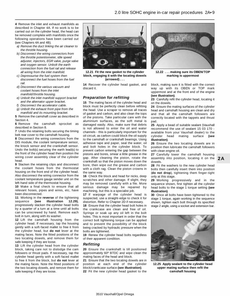
4 Remove the inlet and exhaust manifolds asdescribed in Chapter 4A. If no work is to becarried out on the cylinder head, the head canbe removed complete with manifolds once thefollowing operations have been carried out(see Chapters 4A and 4B).a) Remove the duct linking the air cleaner to
the throttle housing.b) Disconnect the wiring connectors from
the throttle potentiometer, idle speedadjuster, injectors, EGR valve, purge valveand oxygen sensor. Unbolt the earthconnection from the fuel rail and releaseall wiring from the inlet manifold.
c) Depressurise the fuel system thendisconnect the fuel hoses from the fuelrail.
d) Disconnect the various vacuum andcoolant hoses from the inletmanifold/throttle housing.
e) Unbolt the inlet manifold support bracketand the alternator upper bracket.
f) Disconnect the accelerator cable.g) Unbolt the exhaust front pipe from the
manifold and its mounting bracket.5 Remove the camshaft cover as described inSection 4.6 Remove the camshaft sprocket asdescribed in Section 8.7 Undo the retaining bolts securing the timingbelt rear cover to the camshaft housing.8 Disconnect the wiring connectors from theDIS module, the coolant temperature sensor,the knock sensor and the crankshaft sensor.Undo the bolt(s) securing the earth lead(s) tothe front of the cylinder head then position thewiring cover assembly clear of the cylinderhead.9 Slacken the retaining clips and disconnectthe coolant hoses from the thermostathousing on the front end of the cylinder head.Also disconnect the wiring connector from thecoolant temperature gauge sender unit on theleft-hand side of the thermostat housing.10 Make a final check to ensure that allrelevant hoses, pipes and wires, etc, havebeen disconnected.11 Working in the reverse of the tighteningsequence (see illustration 12.29),progressively slacken the cylinder head boltsby a quarter of a turn at a time until all boltscan be unscrewed by hand. Remove eachbolt in turn, along with its washer.12 Lift the camshaft housing from thecylinder head. If necessary, tap the housinggently with a soft-faced mallet to free it fromthe cylinder head, but do not lever at themating faces. Note the fitted positions of thetwo locating dowels, and remove them forsafe keeping if they are loose.13 Lift the cylinder head from the cylinderblock, taking care not to dislodge the camfollowers or thrust pads. If necessary, tap thecylinder head gently with a soft-faced malletto free it from the block, but do not lever atthe mating faces. Note the fitted positions ofthe two locating dowels, and remove them forsafe keeping if they are loose.
14 Recover the cylinder head gasket, anddiscard it.
Preparation for refitting15 The mating faces of the cylinder head andblock must be perfectly clean before refittingthe head. Use a scraper to remove all tracesof gasket and carbon, and also clean the topsof the pistons. Take particular care with thealuminium surfaces, as the soft metal isdamaged easily. Also, make sure that debrisis not allowed to enter the oil and waterchannels - this is particularly important for theoil circuit, as carbon could block the oil supplyto the camshaft or crankshaft bearings. Usingadhesive tape and paper, seal the water, oiland bolt holes in the cylinder block. Toprevent carbon entering the gap between thepistons and bores, smear a little grease in thegap. After cleaning the piston, rotate thecrankshaft so that the piston moves down thebore, then wipe out the grease and carbonwith a cloth rag. Clean the piston crowns inthe same way.16 Check the block and head for nicks, deepscratches and other damage. If slight, theymay be removed carefully with a file. Moreserious damage may be repaired bymachining, but this is a specialist job.17 If warpage of the cylinder head issuspected, use a straight-edge to check it fordistortion. Refer to Chapter 2D if necessary.18 Ensure that the cylinder head bolt holes inthe crankcase are clean and free of oil.Syringe or soak up any oil left in the boltholes. This is most important in order that thecorrect bolt tightening torque can be appliedand to prevent the possibility of the blockbeing cracked by hydraulic pressure when thebolts are tightened.19 Renew the cylinder head bolts regardlessof their apparent condition.
Refitting20 Ensure the crankshaft is till positionedapproximately 60º BTDC and wipe clean themating faces of the head and block.21 Ensure that the two locating dowels are inposition at each end of the cylinderblock/crankcase surface (see illustration).22 Fit the new cylinder head gasket to the
block, making sure it is fitted with the correctway up with its OBEN or TOP markuppermost and at the front end of the engine(see illustration).23 Carefully refit the cylinder head, locating iton the dowels.24 Ensure the mating surfaces of the cylinderhead and camshaft housing are clean and dryand that all the camshaft followers arecorrectly located with the tappets and thrustpad.25 Apply a bead of suitable sealant (Vauxhallrecommend the use of sealant 15 03 170 -available from your Vauxhall dealer) to thecylinder head mating surface (seeillustration).26 Ensure the two locating dowels are inposition then lubricate the camshaft followerswith clean engine oil.27 Carefully lower the camshaft housingassembly into position, locating it on thedowels.28 Fit the washers to the new cylinder headbolts then carefully insert them into position(do not drop), tightening them finger-tightonly at this stage.29 Working progressively and in thesequence shown, first tighten all the cylinderhead bolts to the stage 1 torque setting (seeillustration).30 Once all bolts have been tightened to thestage 1 torque, again working in the sequenceshown, tighten each bolt through its specifiedstage 2 angle, using a socket and extension bar.
2.0 litre SOHC engine in-car repair procedures 2A•9
2A
12.21 Fit the new gasket to the cylinderblock, engaging it with the locating dowels
(arrowed) . . .
12.22 . . . making sure its OBEN/TOPmarking is uppermost
12.25 Apply sealant to the cylinder headupper mating surface then refit the
camshaft housing
3510 Vauxhall/Opel Omega
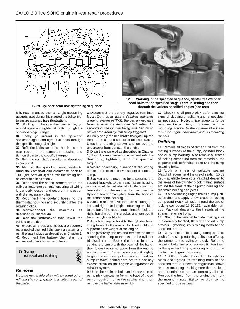
It is recommended that an angle-measuringgauge is used during this stage of the tightening,to ensure accuracy (see illustration).31 Working in the specified sequence, goaround again and tighten all bolts through thespecified stage 3 angle.32 Finally go around in the specifiedsequence again and tighten all bolts throughthe specified stage 4 angle.33 Refit the bolts securing the timing beltrear cover to the camshaft housing andtighten them to the specified torque.34 Refit the camshaft sprocket as describedin Section 8.35 Align all the sprocket timing marks tobring the camshaft and crankshaft back toTDC (see Section 3) then refit the timing beltas described in Section 7.36 Reconnect the wiring connectors to thecylinder head components, ensuring all wiringis correctly routed, and secure it in positionwith the necessary clips.37 Reconnect the coolant hoses to thethermostat housings and securely tighten theretaining clips.38 Refit/reconnect the manifolds asdescribed in Chapter 4A.39 Refit the undercover then lower thevehicle to the floor.40 Ensure all pipes and hoses are securelyreconnected then refill the cooling system andrefit the spark plugs as described in Chapter 1.41 Reconnect the battery then start theengine and check for signs of leaks.
13 Sump - removal and refitting 3
RemovalNote: A new baffle plate will be required onrefitting (the sump gasket is an integral part ofthe plate).
1 Disconnect the battery negative terminal.Note: On models with a Vauxhall anti-theftwarning system (ATWS), the battery negativeterminal must be disconnected within 15seconds of the ignition being switched off toprevent the alarm system being triggered.2 Firmly apply the handbrake then jack up thefront of the car and support it on axle stands.Undo the retaining screws and remove theundercover from beneath the engine.3 Drain the engine oil as described in Chapter1, then fit a new sealing washer and refit thedrain plug, tightening it to the specifiedtorque.4 Where necessary, disconnect the wiringconnector from the oil level sender unit on thesump.5 Slacken and remove the bolts securing thesupport brackets to the transmission housingand sides of the cylinder block. Remove bothbrackets from the engine then remove theflywheel lower cover plate from the base ofthe transmission housing.6 Slacken and remove the nuts securing theleft- and right-hand engine mounting bracketsto the top of the rubber mountings. Unbolt theright-hand mounting bracket and remove itfrom the cylinder block.7 Attach an engine hoist to the cylinder headlifting brackets then raise the hoist until it issupporting the weight of the engine.8 Progressively slacken and remove the boltssecuring the sump to the base of the cylinderblock/oil pump. Break the sump joint bystriking the sump with the palm of the hand,then lower the sump away from the engineand withdraw it. Raise the engine unit slightlyto gain the necessary clearance required forsump removal, taking care not to place anyexcess strain on the engine wiring/hoses orexhaust system.9 Undo the retaining bolts and remove the oilpump pick-up/strainer from the base of the oilpump housing, noting the sealing ring, thenremove the baffle plate assembly.
10 Check the oil pump pick-up/strainer forsigns of clogging or splitting and renew/cleanas necessary. Note: If the sump is to beremoved for any length of time, refit themounting bracket to the cylinder block andlower the engine back down onto its mountingrubbers.
Refitting11 Remove all traces of dirt and oil from themating surfaces of the sump, cylinder blockand oil pump housing. Also remove all tracesof locking compound from the threads of theoil pump pick-up/strainer bolts and the sumpretaining bolts.12 Apply a smear of suitable sealant(Vauxhall recommend the use of sealant 15 03295 - available from your Vauxhall dealer) tothe areas of the cylinder block mating surfacearound the areas of the oil pump housing andrear main bearing cap joints.13 Fit a new sealing ring to the oil pump pick-up/strainer and apply a few drops of lockingcompound (Vauxhall recommend the use oflocking compound 15 10 181 - available fromyour Vauxhall dealer) to the threads of thestrainer retaining bolts.14 Offer up the new baffle plate, making sureit is correctly located, then refit the oil pumpstrainer tightening its retaining bolts to thespecified torque.15 Apply a drop of locking compound toeach of the sump retaining bolts then offer upthe sump to the cylinder block. Refit theretaining bolts and progressively tighten themto the specified torque, working out from thecentre in a diagonal sequence.16 Refit the mounting bracket to the cylinderblock and tighten its retaining bolts to thespecified torque. Lower the engine back downonto its mountings making sure the bracketsand mounting rubbers are correctly aligned.Remove the hoist from the engine then refitthe mounting nuts, tightening them to thespecified torque setting.
2A•10 2.0 litre SOHC engine in-car repair procedures
3510 Vauxhall/Opel Omega
12.29 Cylinder head bolt tightening sequence
12.30 Working in the specified sequence, tighten the cylinderhead bolts to the specified stage 1 torque setting and then
through the various specified angles (see text)
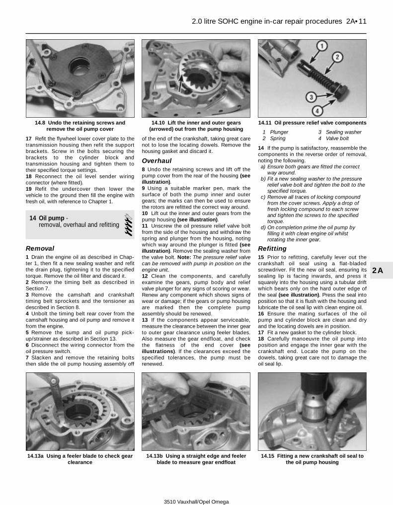
17 Refit the flywheel lower cover plate to thetransmission housing then refit the supportbrackets. Screw in the bolts securing thebrackets to the cylinder block andtransmission housing and tighten them totheir specified torque settings.18 Reconnect the oil level sender wiringconnector (where fitted).19 Refit the undercover then lower thevehicle to the ground then fill the engine withfresh oil, with reference to Chapter 1.
14 Oil pump - removal, overhaul and refitting 4
Removal1 Drain the engine oil as described in Chap-ter 1, then fit a new sealing washer and refitthe drain plug, tightening it to the specifiedtorque. Remove the oil filter and discard it.2 Remove the timing belt as described inSection 7.3 Remove the camshaft and crankshafttiming belt sprockets and the tensioner asdescribed in Section 8.4 Unbolt the timing belt rear cover from thecamshaft housing and oil pump and remove itfrom the engine.5 Remove the sump and oil pump pick-up/strainer as described in Section 13.6 Disconnect the wiring connector from theoil pressure switch.7 Slacken and remove the retaining boltsthen slide the oil pump housing assembly off
of the end of the crankshaft, taking great carenot to lose the locating dowels. Remove thehousing gasket and discard it.
Overhaul8 Undo the retaining screws and lift off thepump cover from the rear of the housing (seeillustration).9 Using a suitable marker pen, mark thesurface of both the pump inner and outergears; the marks can then be used to ensurethe rotors are refitted the correct way around.10 Lift out the inner and outer gears from thepump housing (see illustration).11 Unscrew the oil pressure relief valve boltfrom the side of the housing and withdraw thespring and plunger from the housing, notingwhich way around the plunger is fitted (seeillustration). Remove the sealing washer fromthe valve bolt. Note: The pressure relief valvecan be removed with pump in position on theengine unit.12 Clean the components, and carefullyexamine the gears, pump body and reliefvalve plunger for any signs of scoring or wear.Renew any component which shows signs ofwear or damage; if the gears or pump housingare marked then the complete pumpassembly should be renewed.13 If the components appear serviceable,measure the clearance between the inner gearto outer gear clearance using feeler blades.Also measure the gear endfloat, and checkthe flatness of the end cover (seeillustrations). If the clearances exceed thespecified tolerances, the pump must berenewed.
14 If the pump is satisfactory, reassemble thecomponents in the reverse order of removal,noting the following.a) Ensure both gears are fitted the correct
way around.b) Fit a new sealing washer to the pressure
relief valve bolt and tighten the bolt to thespecified torque.
c) Remove all traces of locking compoundfrom the cover screws. Apply a drop offresh locking compound to each screwand tighten the screws to the specifiedtorque.
d) On completion prime the oil pump byfilling it with clean engine oil whilstrotating the inner gear.
Refitting15 Prior to refitting, carefully lever out thecrankshaft oil seal using a flat-bladedscrewdriver. Fit the new oil seal, ensuring itssealing lip is facing inwards, and press itsquarely into the housing using a tubular driftwhich bears only on the hard outer edge ofthe seal (see illustration). Press the seal intoposition so that it is flush with the housing andlubricate the oil seal lip with clean engine oil.16 Ensure the mating surfaces of the oilpump and cylinder block are clean and dryand the locating dowels are in position.17 Fit a new gasket to the cylinder block.18 Carefully manoeuvre the oil pump intoposition and engage the inner gear with thecrankshaft end. Locate the pump on thedowels, taking great care not to damage theoil seal lip.
2.0 litre SOHC engine in-car repair procedures 2A•11
2A
14.8 Undo the retaining screws andremove the oil pump cover
14.10 Lift the inner and outer gears(arrowed) out from the pump housing
14.11 Oil pressure relief valve components
1 Plunger2 Spring
3 Sealing washer4 Valve bolt
14.13a Using a feeler blade to check gearclearance
14.13b Using a straight edge and feelerblade to measure gear endfloat
14.15 Fitting a new crankshaft oil seal tothe oil pump housing
3510 Vauxhall/Opel Omega

19 Refit the pump housing retaining bolts intheir original locations and tighten them to thespecified torque.20 Reconnect the oil pressure sensor wiringconnector.21 Refit the oil pump pick-up/strainer andsump as described in Section 13.22 Refit the rear timing belt cover to theengine, tightening its retaining bolts to thespecified torque.23 Refit the timing belt sprockets andtensioner then refit the belt as described inSections 7 and 8.24 On completion fit a new oil filter and fill theengine with clean oil as described in Chapter 1.
15 Flywheel/driveplate -removal, inspection and refitting 4
Note: New flywheel/driveplate retaining boltswill be required on refitting.
Removal
Manual transmission models1 Remove the transmission as described inChapter 7A then remove the clutch assemblyas described in Chapter 6.2 Prevent the flywheel from turning by lockingthe ring gear teeth with a similar arrangementto that shown (see illustration). Alternatively,bolt a strap between the flywheel and thecylinder block/crankcase. Make alignmentmarks between the flywheel and crankshaftusing paint or a suitable marker pen.3 Slacken and remove the retaining bolts andremove the flywheel. Do not drop it, as it isvery heavy.
Automatic transmission models4 Remove the transmission as described inChapter 7B.5 Lock the driveplate as described inparagraph 2 then slacken the driveplateretaining bolts.6 Unscrew the retaining bolts and remove theretaining plate, centering ring and driveplatefrom the end of the crankshaft, noting eachcomponents correct fitted location.
Inspection7 On manual transmission models, examinethe flywheel for scoring of the clutch face. Ifthe clutch face is scored, the flywheel may besurface-ground, but renewal is preferable.Check for wear or chipping of the ring gearteeth. Renewal of the ring gear is possible onmodels with a normal flywheel but is not atask for the home mechanic; renewal requiresthe new ring gear to be heated (up to 180º to230ºC) to allow it to be fitted. On dual-massflywheels ring gear renewal is not possible.8 On automatic transmission models closelyexamine the driveplate for ring gear teeth forsigns of wear or damage and check thedriveplate surface for any signs of cracks.9 If there is any doubt about the condition ofthe flywheel/driveplate, seek the advice of aVauxhall dealer or engine reconditioningspecialist. They will be able to advise if it ispossible to recondition it or whether renewalis necessary.
Refitting
Manual transmission models10 Clean the mating surfaces of the flywheeland crankshaft and remove all traces oflocking compound from the flywheel retainingbolt threads in the crankshaft.11 Offer up the flywheel and fit the newretaining bolts. If the original is being refittedalign the marks made prior to removal.12 Lock the flywheel by the method used onremoval, and tighten the retaining bolts to thespecified stage 1 torque setting then angle-tighten the bolts through the specified stage 2angle, using a socket and extension bar, andfinally through the specified stage 3 angle. It isrecommended that an angle-measuringgauge is used during the final stages of thetightening, to ensure accuracy (seeillustrations). If a gauge is not available, usewhite paint to make alignment marks betweenthe bolt head and flywheel prior to tightening;the marks can then be used to check that thebolt has been rotated through the correctangle.13 Refit the clutch as described in Chapter 6then remove the locking tool, and refit thetransmission as described in Chapter 7A.
Automatic transmission models14 Clean the mating surfaces of the driveplateand crankshaft and remove all traces oflocking compound from the driveplateretaining bolt threads in the crankshaft.15 Offer up the driveplate complete with thecentering ring and retaining plate, makingsure all components are fitted the correct wayaround, then screw in the new retaining bolts.16 Tighten the retaining bolts through thespecified torque and angles as described inparagraph 12 then remove the locking tooland refit the transmission as described inChapter 7B.
16 Crankshaft oil seals - renewal 4
Front (timing belt end) oil seal1 Remove the crankshaft sprocket asdescribed in Section 8.2 Carefully punch or drill two small holesopposite each other in the oil seal. Screw aself-tapping screw into each and pull on thescrews with pliers to extract the seal (seeillustration). Alternatively carefully lever theseal out of position.Caution: Great care must be taken to avoiddamage to the oil pump3 Clean the seal housing and polish off anyburrs or raised edges which may have causedthe seal to fail in the first place.
2A•12 2.0 litre SOHC engine in-car repair procedures
15.2 Lock the flywheel/driveplate ring gearwith a tool similar to that shown
15.12a On manual transmission models,tighten the flywheel bolts to the specified
stage 1 torque setting . . .
15.12b . . . then tighten them through thespecified stage 2 and 3 angles
16.2 Removing the crankshaft front oilseal
3510 Vauxhall/Opel Omega

4 Lubricate the lips of the new seal with cleanengine oil and ease it into position on the endof the shaft. Press the seal squarely intoposition until it is flush with the housing. Ifnecessary, a suitable tubular drift, such as asocket, which bears only on the hard outeredge of the seal can be used to tap the sealinto position (see illustration). Take greatcare not to damage the seal lips during fittingand ensure that the seal lips face inwards.5 Wash off any traces of oil, then refit thecrankshaft sprocket as described in Section 8.
Rear (flywheel/driveplate end)oil seal6 Remove the flywheel/driveplate asdescribed in Section 15.7 Renew the seal as described in paragraphs 2to 4.8 Refit the flywheel/driveplate as described inSection 15.
17 Engine/transmissionmountings - inspection and renewal
3Inspection1 If improved access is required, raise thefront of the car and support it securely on axlestands. Undo the retaining bolts and removethe undercover from beneath the engine unit.
2 Check the mounting rubber to see if it iscracked, hardened or separated from themetal at any point; renew the mounting if anysuch damage or deterioration is evident.3 Check that all the mounting’s fasteners aresecurely tightened; use a torque wrench tocheck if possible.4 Using a large screwdriver or a pry bar,check for wear in the mounting by carefullylevering against it to check for free play;where this is not possible, enlist the aid of anassistant to move the engine/transmissionunit back and forth, or from side to side, whileyou watch the mounting. While some free playis to be expected even from newcomponents, excessive wear should beobvious. If excessive free play is found, checkfirst that the fasteners are correctly secured,then renew any worn components asdescribed below.
Renewal
Left- and right-hand engine mountingsNote: It is recommended that the enginemountings are replaced as a matched pair.5 Firmly apply the handbrake then jack up thefront of the vehicle and support it on axlestands. Undo the retaining screws and removethe undercover from beneath the engine.6 Support the weight of the engine/transmission using a trolley jack with a blockof wood placed on its head. Alternativelyattach an engine hoist to the lifting bracketson the cylinder head and use the hoist tosupport the engine.7 Unscrew the upper and lower nuts securingthe relevant engine mounting to the cylinderblock bracket and subframe then raise theengine unit slightly and manoeuvre themounting out of position. If necessary themounting bracket can be unbolted andremoved from the cylinder block. Note: Takegreat care not to place any excess stress onany engine wiring/hoses or the exhaustsystem or when raising the engine.8 Check all components for signs of wear ordamage, and renew as necessary.9 On refitting, refit the mounting to the
subframe aligning its locating lug with thesubframe slot then refit the lower nut andtighten to the specified torque.10 Refit the mounting bracket (whereremoved) to the cylinder block and tighten itsretaining bolts to the specified torque.11 Lower the engine unit back down onto themounting, making sure it is correctly located,then remove the jack/hoist (as applicable). Fitthe upper retaining nut to the mounting andtighten it to the specified torque.12 Refit the undercover then lower thevehicle to the ground.
Transmission unit rear mounting13 Firmly apply the handbrake then jack upthe front of the vehicle and support it on axlestands.14 Place a jack with a block of wood beneaththe transmission, and raise the jack to takethe weight of the transmission.15 With the transmission securely supported,slacken and remove the bolts securing thetransmission unit rear mounting crossmemberto the vehicle body. Unscrew the nutssecuring the crossmember to the mountingand remove it from the vehicle.16 Slacken and remove the bolts and removethe mounting from the base of thetransmission unit.17 Check all components for signs of wear ordamage, and renew as necessary. Remove alltraces of locking compound from thecrossmember to body bolt threads.18 Fit the mounting to the transmission unitand tighten its retaining bolts to the specifiedtorque.19 Refit the crossmember to the mountingand lightly tighten its retaining nuts.20 Apply a few drops of thread lockingcompound (Vauxhall recommend the use oflocking compound 15 10 181 - available fromyour Vauxhall dealer) to the threads of eachcrossmember to body bolt then refit bothbolts and tighten them to the specified torque.21 Remove the jack from underneath thetransmission unit then tighten the mounting tocrossmember nuts to the specified torquebefore lowering the vehicle to the ground.
2.0 litre SOHC engine in-car repair procedures 2A•13
2A
16.4 Fitting a new crankshaft front oil seal
3510 Vauxhall/Opel Omega

3510 Vauxhall/Opel Omega
2B•1
2B
Chapter 2 Part B:2.0 litre DOHC engine in-car repair procedures
GeneralEngine type . . . . . . . . . . . . . . . . . . . . . . . . . . . . . . . . . . . . . . . . . . . . . . . Four-cylinder, in-line, water-cooled. Double overhead camshaft, belt-
drivenManufacturer’s engine code . . . . . . . . . . . . . . . . . . . . . . . . . . . . . . . . . . X20XEVBore . . . . . . . . . . . . . . . . . . . . . . . . . . . . . . . . . . . . . . . . . . . . . . . . . . . . 86.0 mmStroke . . . . . . . . . . . . . . . . . . . . . . . . . . . . . . . . . . . . . . . . . . . . . . . . . . . 86.0 mmCapacity . . . . . . . . . . . . . . . . . . . . . . . . . . . . . . . . . . . . . . . . . . . . . . . . . 1998 ccFiring order . . . . . . . . . . . . . . . . . . . . . . . . . . . . . . . . . . . . . . . . . . . . . . . 1-3-4-2 (No 1 cylinder at timing belt end)Direction of crankshaft rotation . . . . . . . . . . . . . . . . . . . . . . . . . . . . . . . Clockwise (viewed from timing belt end of engine)Compression ratio . . . . . . . . . . . . . . . . . . . . . . . . . . . . . . . . . . . . . . . . . 10.8:1Maximum power . . . . . . . . . . . . . . . . . . . . . . . . . . . . . . . . . . . . . . . . . . . 100 kW at 5600 rpmMaximum torque . . . . . . . . . . . . . . . . . . . . . . . . . . . . . . . . . . . . . . . . . . . 185 Nm at 4000 rpm
Compression pressuresStandard . . . . . . . . . . . . . . . . . . . . . . . . . . . . . . . . . . . . . . . . . . . . . . . . . 12 to 15 bar (174 to 218 psi)Maximum difference between any two cylinders . . . . . . . . . . . . . . . . . . 1 bar (15 psi)
CamshaftCam lift . . . . . . . . . . . . . . . . . . . . . . . . . . . . . . . . . . . . . . . . . . . . . . . . . . 9.2 mm
Lubrication systemOil pump type . . . . . . . . . . . . . . . . . . . . . . . . . . . . . . . . . . . . . . . . . . . . . Gear-type, driven directly from crankshaftMinimum permissible oil pressure at idle speed, with engine
at operating temperature (oil temperature of at least 80°C) . . . . . . . . 1.5 bar (22 psi)Oil pump clearances:
Gear teeth clearance . . . . . . . . . . . . . . . . . . . . . . . . . . . . . . . . . . . . . . 0.08 to 0.15 mmGear endfloat . . . . . . . . . . . . . . . . . . . . . . . . . . . . . . . . . . . . . . . . . . . 0.03 to 0.10 mm
Camshafts and followers - removal, inspection and refitting . . . . . . 10Camshaft cover - removal and refitting . . . . . . . . . . . . . . . . . . . . . . . 4Camshaft oil seals - renewal . . . . . . . . . . . . . . . . . . . . . . . . . . . . . . . 9Compression test - description and interpretation . . . . . . . . . . . . . . 2Crankshaft balancer unit (1998 model year onwards) - removal,
refitting and adjustment . . . . . . . . . . . . . . . . . . . . . . . . . . . . . . . . . 14Crankshaft oil seals - renewal . . . . . . . . . . . . . . . . . . . . . . . . . . . . . . 16Crankshaft pulley - removal and refitting . . . . . . . . . . . . . . . . . . . . . . 5Cylinder head - removal and refitting . . . . . . . . . . . . . . . . . . . . . . . . 11Engine oil and filter - renewal . . . . . . . . . . . . . . . . . . . . .See Chapter 1Engine oil level check . . . . . . . . . . . . . . . . . . . . . . .See Weekly checks
Engine/transmission mountings - inspection and renewal . . . . . . . . 17Flywheel/driveplate - removal, inspection and refitting . . . . . . . . . . . 15General information . . . . . . . . . . . . . . . . . . . . . . . . . . . . . . . . . . . . . . 1Oil pump - removal, overhaul and refitting . . . . . . . . . . . . . . . . . . . . 13Sump - removal and refitting . . . . . . . . . . . . . . . . . . . . . . . . . . . . . . . 12Timing belt - removal and refitting . . . . . . . . . . . . . . . . . . . . . . . . . . . 7Timing belt covers - removal and refitting . . . . . . . . . . . . . . . . . . . . . 6Timing belt sprockets, tensioner and idler pulleys - removal and
refitting . . . . . . . . . . . . . . . . . . . . . . . . . . . . . . . . . . . . . . . . . . . . . . 8Top dead centre (TDC) for No 1 piston - locating . . . . . . . . . . . . . . . 3
Specifications
Contents
Easy, suitable fornovice with littleexperience
Fairly easy, suitablefor beginner withsome experience
Fairly difficult,suitable for competentDIY mechanic
Difficult, suitable forexperienced DIYmechanic
Very difficult,suitable for expert DIYor professional
Degrees of difficulty
54321
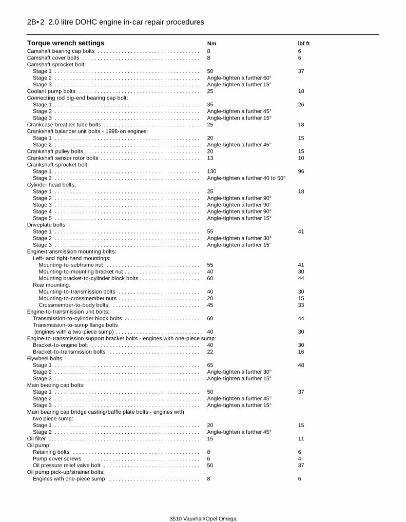
Torque wrench settings Nm lbf ftCamshaft bearing cap bolts . . . . . . . . . . . . . . . . . . . . . . . . . . . . . . . . . . 8 6Camshaft cover bolts . . . . . . . . . . . . . . . . . . . . . . . . . . . . . . . . . . . . . . . 8 6Camshaft sprocket bolt:
Stage 1 . . . . . . . . . . . . . . . . . . . . . . . . . . . . . . . . . . . . . . . . . . . . . . . . 50 37Stage 2 . . . . . . . . . . . . . . . . . . . . . . . . . . . . . . . . . . . . . . . . . . . . . . . . Angle-tighten a further 60°Stage 3 . . . . . . . . . . . . . . . . . . . . . . . . . . . . . . . . . . . . . . . . . . . . . . . . Angle-tighten a further 15°
Coolant pump bolts . . . . . . . . . . . . . . . . . . . . . . . . . . . . . . . . . . . . . . . . 25 18Connecting rod big-end bearing cap bolt:
Stage 1 . . . . . . . . . . . . . . . . . . . . . . . . . . . . . . . . . . . . . . . . . . . . . . . . 35 26Stage 2 . . . . . . . . . . . . . . . . . . . . . . . . . . . . . . . . . . . . . . . . . . . . . . . . Angle-tighten a further 45°Stage 3 . . . . . . . . . . . . . . . . . . . . . . . . . . . . . . . . . . . . . . . . . . . . . . . . Angle-tighten a further 15°
Crankcase breather tube bolts . . . . . . . . . . . . . . . . . . . . . . . . . . . . . . . . 25 18Crankshaft balancer unit bolts - 1998-on engines:
Stage 1 . . . . . . . . . . . . . . . . . . . . . . . . . . . . . . . . . . . . . . . . . . . . . . . . 20 15Stage 2 . . . . . . . . . . . . . . . . . . . . . . . . . . . . . . . . . . . . . . . . . . . . . . . . Angle-tighten a further 45°
Crankshaft pulley bolts . . . . . . . . . . . . . . . . . . . . . . . . . . . . . . . . . . . . . . 20 15Crankshaft sensor rotor bolts . . . . . . . . . . . . . . . . . . . . . . . . . . . . . . . . . 13 10Crankshaft sprocket bolt:
Stage 1 . . . . . . . . . . . . . . . . . . . . . . . . . . . . . . . . . . . . . . . . . . . . . . . . 130 96Stage 2 . . . . . . . . . . . . . . . . . . . . . . . . . . . . . . . . . . . . . . . . . . . . . . . . Angle-tighten a further 40 to 50°
Cylinder head bolts:Stage 1 . . . . . . . . . . . . . . . . . . . . . . . . . . . . . . . . . . . . . . . . . . . . . . . . 25 18Stage 2 . . . . . . . . . . . . . . . . . . . . . . . . . . . . . . . . . . . . . . . . . . . . . . . . Angle-tighten a further 90°Stage 3 . . . . . . . . . . . . . . . . . . . . . . . . . . . . . . . . . . . . . . . . . . . . . . . . Angle-tighten a further 90°Stage 4 . . . . . . . . . . . . . . . . . . . . . . . . . . . . . . . . . . . . . . . . . . . . . . . . Angle-tighten a further 90°Stage 5 . . . . . . . . . . . . . . . . . . . . . . . . . . . . . . . . . . . . . . . . . . . . . . . . Angle-tighten a further 15°
Driveplate bolts:Stage 1 . . . . . . . . . . . . . . . . . . . . . . . . . . . . . . . . . . . . . . . . . . . . . . . . 55 41Stage 2 . . . . . . . . . . . . . . . . . . . . . . . . . . . . . . . . . . . . . . . . . . . . . . . . Angle-tighten a further 30°Stage 3 . . . . . . . . . . . . . . . . . . . . . . . . . . . . . . . . . . . . . . . . . . . . . . . . Angle-tighten a further 15°
Engine/transmission mounting bolts:Left- and right-hand mountings:
Mounting-to-subframe nut . . . . . . . . . . . . . . . . . . . . . . . . . . . . . . . 55 41Mounting-to-mounting bracket nut . . . . . . . . . . . . . . . . . . . . . . . . . 40 30Mounting bracket-to-cylinder block bolts . . . . . . . . . . . . . . . . . . . . 60 44
Rear mounting:Mounting-to-transmission bolts . . . . . . . . . . . . . . . . . . . . . . . . . . . 40 30Mounting-to-crossmember nuts . . . . . . . . . . . . . . . . . . . . . . . . . . . 20 15Crossmember-to-body bolts . . . . . . . . . . . . . . . . . . . . . . . . . . . . . 45 33
Engine-to-transmission unit bolts:Transmission-to-cylinder block bolts . . . . . . . . . . . . . . . . . . . . . . . . . 60 44Transmission-to-sump flange bolts(engines with a two-piece sump) . . . . . . . . . . . . . . . . . . . . . . . . . . . . 40 30
Engine-to-transmission support bracket bolts - engines with one-piece sump:Bracket-to-engine bolt . . . . . . . . . . . . . . . . . . . . . . . . . . . . . . . . . . . . 40 30Bracket-to-transmission bolts . . . . . . . . . . . . . . . . . . . . . . . . . . . . . . 22 16
Flywheel bolts:Stage 1 . . . . . . . . . . . . . . . . . . . . . . . . . . . . . . . . . . . . . . . . . . . . . . . . 65 48Stage 2 . . . . . . . . . . . . . . . . . . . . . . . . . . . . . . . . . . . . . . . . . . . . . . . . Angle-tighten a further 30°Stage 3 . . . . . . . . . . . . . . . . . . . . . . . . . . . . . . . . . . . . . . . . . . . . . . . . Angle-tighten a further 15°
Main bearing cap bolts:Stage 1 . . . . . . . . . . . . . . . . . . . . . . . . . . . . . . . . . . . . . . . . . . . . . . . . 50 37Stage 2 . . . . . . . . . . . . . . . . . . . . . . . . . . . . . . . . . . . . . . . . . . . . . . . . Angle-tighten a further 45°Stage 3 . . . . . . . . . . . . . . . . . . . . . . . . . . . . . . . . . . . . . . . . . . . . . . . . Angle-tighten a further 15°
Main bearing cap bridge casting/baffle plate bolts - engines with two piece sump:Stage 1 . . . . . . . . . . . . . . . . . . . . . . . . . . . . . . . . . . . . . . . . . . . . . . . . 20 15Stage 2 . . . . . . . . . . . . . . . . . . . . . . . . . . . . . . . . . . . . . . . . . . . . . . . . Angle-tighten a further 45°
Oil filter . . . . . . . . . . . . . . . . . . . . . . . . . . . . . . . . . . . . . . . . . . . . . . . . . . 15 11Oil pump:
Retaining bolts . . . . . . . . . . . . . . . . . . . . . . . . . . . . . . . . . . . . . . . . . . 8 6Pump cover screws . . . . . . . . . . . . . . . . . . . . . . . . . . . . . . . . . . . . . . 6 4Oil pressure relief valve bolt . . . . . . . . . . . . . . . . . . . . . . . . . . . . . . . . 50 37
Oil pump pick-up/strainer bolts:Engines with one-piece sump . . . . . . . . . . . . . . . . . . . . . . . . . . . . . . 8 6
2B•2 2.0 litre DOHC engine in-car repair procedures
3510 Vauxhall/Opel Omega

Torque wrench settings (continued) Nm lbf ftOil pump pick-up/strainer bolts (continued):
Engines with two piece sump:Pick-up-to-oil pump housing bolts . . . . . . . . . . . . . . . . . . . . . . . . . 8 6Pick-up-to-casting/balancer unit bolts:
M6 bolts . . . . . . . . . . . . . . . . . . . . . . . . . . . . . . . . . . . . . . . . . . . 10 7M8 bolts . . . . . . . . . . . . . . . . . . . . . . . . . . . . . . . . . . . . . . . . . . . 20 15
Sump bolts:One-piece sump . . . . . . . . . . . . . . . . . . . . . . . . . . . . . . . . . . . . . . . . . 15 11Two-piece sump:
Sump pan bolts:Stage 1 . . . . . . . . . . . . . . . . . . . . . . . . . . . . . . . . . . . . . . . . . . . . 8 6Stage 2 . . . . . . . . . . . . . . . . . . . . . . . . . . . . . . . . . . . . . . . . . . . . Angle-tighten a further 30°
Main casting bolts:Casting-to-cylinder block/oil pump bolts . . . . . . . . . . . . . . . . . . 20 15Casting flange-to-transmission bolts . . . . . . . . . . . . . . . . . . . . . 40 30
Sump drain plug:Hex-head bolt . . . . . . . . . . . . . . . . . . . . . . . . . . . . . . . . . . . . . . . . . . . 45 33Torx-head bolt . . . . . . . . . . . . . . . . . . . . . . . . . . . . . . . . . . . . . . . . . . 10 7
Timing belt cover bolts:Outer cover . . . . . . . . . . . . . . . . . . . . . . . . . . . . . . . . . . . . . . . . . . . . . 6 4Rear cover . . . . . . . . . . . . . . . . . . . . . . . . . . . . . . . . . . . . . . . . . . . . . . 8 6
Timing belt idler pulley:Pulley bolt . . . . . . . . . . . . . . . . . . . . . . . . . . . . . . . . . . . . . . . . . . . . . . 25 18Mounting bracket bolts . . . . . . . . . . . . . . . . . . . . . . . . . . . . . . . . . . . . 25 18
Timing belt tensioner bolt . . . . . . . . . . . . . . . . . . . . . . . . . . . . . . . . . . . . 20 15
2.0 litre DOHC engine in-car repair procedures 2B•3
2B
3510 Vauxhall/Opel Omega
1 General information
How to use this Chapter1 This Part of Chapter 2 is devoted to in-carrepair procedures for the engine. Allprocedures concerning engine removal andrefitting, and engine block/cylinder headoverhaul can be found in Chapter 2D.2 Most of the operations included in this Partare based on the assumption that the engineis still installed in the car. Therefore, if thisinformation is being used during a completeengine overhaul, with the engine alreadyremoved, many of the steps included here willnot apply.
Engine description3 The engine is a double overhead camshaft,four-cylinder, in-line unit, mounted at the frontof the car with the transmission on its rear.This engine is often referred to as the 2.0 litreECOTEC engine (Emission ConsumptionOptimized TEChnology).4 The cylinder block is of the dry-liner type.The crankshaft is supported within thecylinder block on five shell-type mainbearings. Thrustwashers are fitted to number3 main bearing, to control crankshaft endfloat.5 The connecting rods are attached to thecrankshaft by horizontally split shell-type big-end bearings, and to the pistons byinterference-fit gudgeon pins. The aluminiumalloy pistons are of the slipper type, and arefitted with three piston rings, comprising two
compression rings and a scraper-type oilcontrol ring.6 The camshafts run directly in the cylinderhead, and are driven by the crankshaft via atoothed rubber timing belt (which also drivesthe coolant pump). The camshafts operateeach valve via a follower. Each followerincorporates a hydraulic self-adjusting valvewhich automatically adjust the valveclearances.7 Lubrication is by pressure-feed from agear-type oil pump, which is mounted on thefront end of the crankshaft. It draws oilthrough a strainer located in the sump, andthen forces it through an externally mountedfull-flow cartridge-type filter. The oil flows intogalleries in the main bearing cap bridgearrangement and cylinder block/crankcase,from where it is distributed to the crankshaft(main bearings) and camshafts. The big-endbearings are supplied with oil via internaldrillings in the crankshaft, while the camshaftbearings also receive a pressurised supply.The camshaft lobes and valves are lubricatedby splash, as are all other enginecomponents.8 On later (1998 model year onwards)engines, a crankshaft balancer unit is fitted tothe engine to smooth out the forces whichoccur during normal crankshaft/pistonmovement. The balancer unit houses twobalance shafts and is bolted onto the base ofthe cylinder block, directly beneath number 2cylinder. The balancer shaft gears are meshedtogether and the gear of the first shaft isdriven by the crankshaft via a gear whichforms the third web of the crankshaft. Thecrankshaft gear has twice as many teeth as
the balance shaft gears and so drives thebalance shaft at twice the speed of thecrankshaft, the first balance shaft rotates inthe opposite direction to the crankshaft andthe second in the same direction.9 A semi-closed crankcase ventilation systemis employed; crankcase fumes are drawn fromcylinder head cover, and passed via a hose tothe inlet manifold.
Repair operations possible withthe engine in the car10 The following operations can be carriedout without having to remove the engine fromthe vehicle.a) Removal and refitting of the cylinder
head.b) Removal and refitting of the timing belt
and sprockets.c) Renewal of the camshaft oil seals.d) Removal and refitting of the camshafts
and followers.e) Removal and refitting of the sump.f) Removal and refitting of the connecting
rods and pistons*.g) Removal and refitting of the oil pump.h) Renewal of the crankshaft balancer unit -
1998 on engines.i) Renewal of the crankshaft oil seals.j) Renewal of the engine mountings.k) Removal and refitting of the
flywheel/driveplate.* Although the operation marked with an asteriskcan be carried out with the engine in the car afterremoval of the sump, it is better for the engine tobe removed, in the interests of cleanliness andimproved access. For this reason, the procedureis described in Chapter 2D.
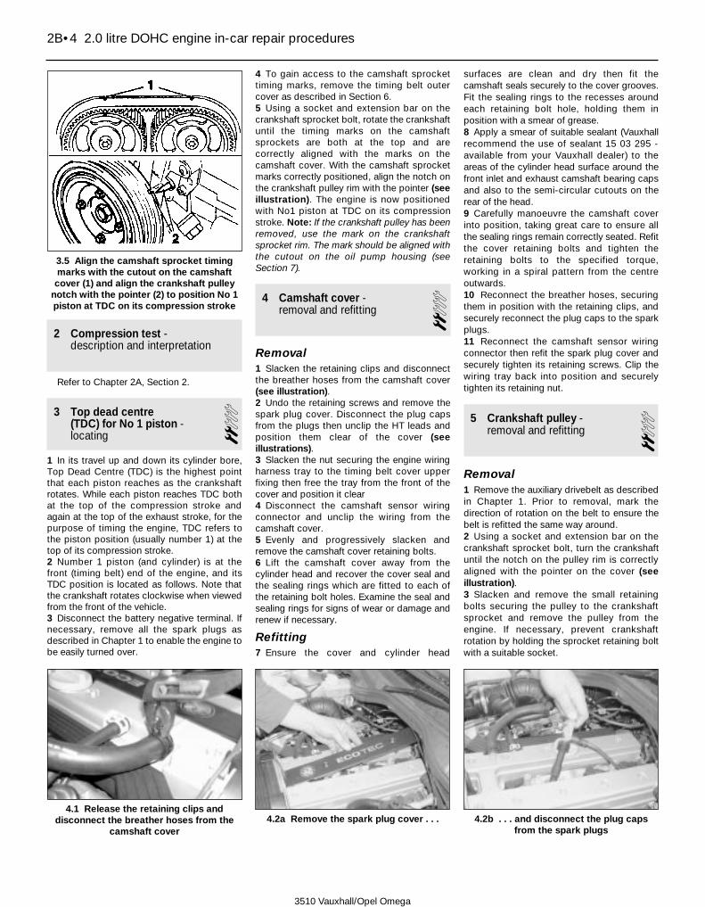
2 Compression test -description and interpretation
Refer to Chapter 2A, Section 2.
3 Top dead centre (TDC) for No 1 piston -locating
21 In its travel up and down its cylinder bore,Top Dead Centre (TDC) is the highest pointthat each piston reaches as the crankshaftrotates. While each piston reaches TDC bothat the top of the compression stroke andagain at the top of the exhaust stroke, for thepurpose of timing the engine, TDC refers tothe piston position (usually number 1) at thetop of its compression stroke.2 Number 1 piston (and cylinder) is at thefront (timing belt) end of the engine, and itsTDC position is located as follows. Note thatthe crankshaft rotates clockwise when viewedfrom the front of the vehicle.3 Disconnect the battery negative terminal. Ifnecessary, remove all the spark plugs asdescribed in Chapter 1 to enable the engine tobe easily turned over.
4 To gain access to the camshaft sprockettiming marks, remove the timing belt outercover as described in Section 6.5 Using a socket and extension bar on thecrankshaft sprocket bolt, rotate the crankshaftuntil the timing marks on the camshaftsprockets are both at the top and arecorrectly aligned with the marks on thecamshaft cover. With the camshaft sprocketmarks correctly positioned, align the notch onthe crankshaft pulley rim with the pointer (seeillustration). The engine is now positionedwith No1 piston at TDC on its compressionstroke. Note: If the crankshaft pulley has beenremoved, use the mark on the crankshaftsprocket rim. The mark should be aligned withthe cutout on the oil pump housing (seeSection 7).
4 Camshaft cover - removal and refitting 2
Removal1 Slacken the retaining clips and disconnectthe breather hoses from the camshaft cover(see illustration).2 Undo the retaining screws and remove thespark plug cover. Disconnect the plug capsfrom the plugs then unclip the HT leads andposition them clear of the cover (seeillustrations).3 Slacken the nut securing the engine wiringharness tray to the timing belt cover upperfixing then free the tray from the front of thecover and position it clear4 Disconnect the camshaft sensor wiringconnector and unclip the wiring from thecamshaft cover.5 Evenly and progressively slacken andremove the camshaft cover retaining bolts.6 Lift the camshaft cover away from thecylinder head and recover the cover seal andthe sealing rings which are fitted to each ofthe retaining bolt holes. Examine the seal andsealing rings for signs of wear or damage andrenew if necessary.
Refitting7 Ensure the cover and cylinder head
surfaces are clean and dry then fit thecamshaft seals securely to the cover grooves.Fit the sealing rings to the recesses aroundeach retaining bolt hole, holding them inposition with a smear of grease.8 Apply a smear of suitable sealant (Vauxhallrecommend the use of sealant 15 03 295 -available from your Vauxhall dealer) to theareas of the cylinder head surface around thefront inlet and exhaust camshaft bearing capsand also to the semi-circular cutouts on therear of the head.9 Carefully manoeuvre the camshaft coverinto position, taking great care to ensure allthe sealing rings remain correctly seated. Refitthe cover retaining bolts and tighten theretaining bolts to the specified torque,working in a spiral pattern from the centreoutwards.10 Reconnect the breather hoses, securingthem in position with the retaining clips, andsecurely reconnect the plug caps to the sparkplugs.11 Reconnect the camshaft sensor wiringconnector then refit the spark plug cover andsecurely tighten its retaining screws. Clip thewiring tray back into position and securelytighten its retaining nut.
5 Crankshaft pulley - removal and refitting 2
Removal1 Remove the auxiliary drivebelt as describedin Chapter 1. Prior to removal, mark thedirection of rotation on the belt to ensure thebelt is refitted the same way around.2 Using a socket and extension bar on thecrankshaft sprocket bolt, turn the crankshaftuntil the notch on the pulley rim is correctlyaligned with the pointer on the cover (seeillustration).3 Slacken and remove the small retainingbolts securing the pulley to the crankshaftsprocket and remove the pulley from theengine. If necessary, prevent crankshaftrotation by holding the sprocket retaining boltwith a suitable socket.
2B•4 2.0 litre DOHC engine in-car repair procedures
3.5 Align the camshaft sprocket timingmarks with the cutout on the camshaftcover (1) and align the crankshaft pulley
notch with the pointer (2) to position No 1piston at TDC on its compression stroke
4.1 Release the retaining clips anddisconnect the breather hoses from the
camshaft cover4.2a Remove the spark plug cover . . . 4.2b . . . and disconnect the plug caps
from the spark plugs
3510 Vauxhall/Opel Omega

Refitting4 Check that the crankshaft sprocket mark isstill aligned with the mark on the oil pumphousing then manoeuvre the crankshaft pulley
into position. Align the notch on the pulley rimwith the pointer then seat the pulley on thesprocket and tighten its retaining bolts to thespecified torque.5 Refit the auxiliary drivebelt as described inChapter 1 using the mark made prior toremoval to ensure the belt is fitted the correctway around.
6 Timing belt covers - removal and refitting 3
Outer cover
Removal1 Remove the auxiliary drivebelt as describedin Chapter 1. Prior to removal, mark thedirection of rotation on the belt to ensure thebelt is refitted the same way around.2 Slacken and remove the nut securing theengine wiring harness tray to the outer coverupper mounting and free the tray assemblyfrom the timing belt cover. Unclip the coverfrom the tray then free the wiring harness andcoolant hose and remove the tray from theengine compartment (see illustrations).3 Slacken and remove the retaining bolts,along with their washers and outer rubberspacers, then remove the outer cover from theengine unit along with its seal. Once the coverhas been removed, recover inner rubberspacers from the mountings (seeillustrations).
Refitting4 Ensure the inner rubber spacers arecorrectly fitted to each of the mountings thenmanoeuvre the cover into position (seeillustration).5 Fit the washers and outer rubber spacers tothe mounting bolts then refit the bolts in theiroriginal locations and tighten them to thespecified torque (see illustration).6 Seat the wiring harness correctly in the traythen refit the tray cover. Clip the tray securelyonto the timing belt cover and securely tightenits retaining nut.7 Refit the auxiliary drivebelt as described inChapter 1 using the mark made prior toremoval to ensure the belt is fitted the correctway around.
Rear cover
Removal8 Remove the timing belt as described inSection 7.9 Remove the camshaft sprockets,crankshaft sprocket, the timing belt tensionerand the idler pulley assembly as described inSection 8.10 Unbolt the camshaft sensor from thecylinder head.11 Undo the retaining bolts, noting theircorrect fitted locations, and remove the rearcover from the engine unit.
Refitting12 Refitting is the reverse of removal,tightening all bolts to the specified torque.
2.0 litre DOHC engine in-car repair procedures 2B•5
2B
5.2 Align the crankshaft pulley notch withthe pointer on the cover (arrowed - shown
with timing belt outer cover removed)
6.2b . . . then unclip the cover . . .6.2c . . . and free the wiring and coolant
hose and remove the tray from the enginecompartment
6.3a Slacken and remove the coverretaining bolts (upper bolt shown) andrecover the outer rubber spacers . . .
6.4 Ensure the inner rubber spacers arecorrectly fitted to the mountings before
installing the outer cover . . .
6.5 . . . and ensure the outer spacers arecorrectly positioned before refitting the
retaining bolts
6.2a Undo the retaining nut and free thewiring tray from the outer cover . . .
6.3b . . . then remove the outer cover fromthe engine
3510 Vauxhall/Opel Omega

7 Timing belt - removal and refitting 3
Note: The timing belt must be removed andrefitted with the engine cold.
Removal1 Disconnect the battery negative terminalthen position No1 cylinder at TDC on itscompression stroke as described in Section 3.Note: On models with a Vauxhall anti-theftwarning system (ATWS), the battery negativeterminal must be disconnected within 15seconds of the ignition being switched off toprevent the alarm system being triggered.2 Remove the crankshaft pulley as describedin Section 5.3 Check the camshaft sprocket timing marksare correctly aligned with the camshaft covermarks and the crankshaft sprocket timingmark is aligned with the cutout on the oilpump housing.4 Slacken the timing belt tensioner bolt (see
illustration). Using an Allen key, rotate thetensioner arm clockwise to its stop, to relievethe tension in the timing belt, and hold it inposition by and securely tighten the retainingbolt.5 Slide the timing belt off from its sprocketsand remove it from the engine. If the belt is tobe re-used, use white paint or similar to markthe direction of rotation on the belt. Do notrotate the crankshaft or camshafts until thetiming belt has been refitted.6 Check the timing belt carefully for any signsof uneven wear, splitting or oil contamination,and renew it if there is the slightest doubtabout its condition. If the engine is undergoingan overhaul and has covered 40 000 miles orit was more than 4 years since the original beltwas fitted, renew the belt as a matter ofcourse, regardless of its apparent condition(from 1997 onwards the belt renewal intervalwas increased to 80 000 miles or 8 years). Ifsigns of oil contamination are found, trace thesource of the oil leak and rectify it, then washdown the engine timing belt area and allrelated components to remove all traces of oil.
Refitting7 On reassembly, thoroughly clean the timingbelt sprockets and tensioner/idler pulleys.8 Check that the crankshaft sprocket timingmark is still aligned with the cutout on the oilpump housing and the camshaft sprocketmarks are aligned with the marks on thecamshaft cover. If the camshaft cover hasbeen removed, align the sprocket marks withthe lugs on the top of the camshaft frontbearing caps (see illustration).9 Fit the timing belt over the crankshaft andcamshaft sprockets and around the idlerpulleys, ensuring that the belt left-hand run istaut (ie, all slack is on the tensioner side of thebelt), then fit the belt over the coolant pumpsprocket and tensioner pulley. Do not twistthe belt sharply while refitting it. Ensure thatthe belt teeth are correctly seated centrally inthe sprockets, and that the timing marksremain in alignment. If a used belt is beingrefitted, ensure that the arrow mark made onremoval points in the normal direction ofrotation, as before.10 Slacken the timing belt tensioner bolt torelease the tensioner spring. Rotate thetensioner arm anti-clockwise until thetensioner pointer is fully over against its stop,without exerting any excess strain on the belt(see illustration). Hold the tensioner inposition and securely tighten its retaining bolt.
2B•6 2.0 litre DOHC engine in-car repair procedures
7.4 Slacken the timing belt tensioner bolt(1) and rotate the tensioner clockwiseusing an Allen key in the arm cutout (2)
7.10 Tension the belt by rotating thetensioner arm fully anti-clockwise until the
pointer is positioned as shown
3510 Vauxhall/Opel Omega
7.8 Align the camshaft sprocket marks (1) with the marks on the bearing caps (2) orcover and ensure the crankshaft sprocket timing mark is correctly aligned with the oil
pump cutout (3)
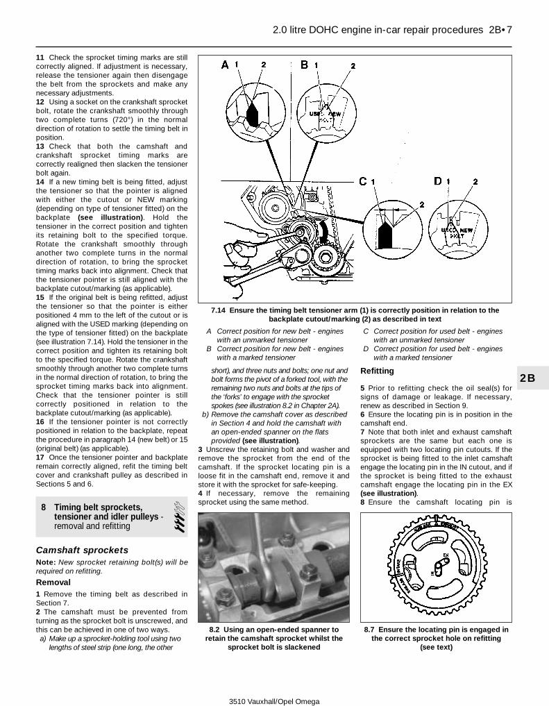
11 Check the sprocket timing marks are stillcorrectly aligned. If adjustment is necessary,release the tensioner again then disengagethe belt from the sprockets and make anynecessary adjustments.12 Using a socket on the crankshaft sprocketbolt, rotate the crankshaft smoothly throughtwo complete turns (720°) in the normaldirection of rotation to settle the timing belt inposition.13 Check that both the camshaft andcrankshaft sprocket timing marks arecorrectly realigned then slacken the tensionerbolt again.14 If a new timing belt is being fitted, adjustthe tensioner so that the pointer is alignedwith either the cutout or NEW marking(depending on type of tensioner fitted) on thebackplate (see illustration). Hold thetensioner in the correct position and tightenits retaining bolt to the specified torque.Rotate the crankshaft smoothly throughanother two complete turns in the normaldirection of rotation, to bring the sprockettiming marks back into alignment. Check thatthe tensioner pointer is still aligned with thebackplate cutout/marking (as applicable).15 If the original belt is being refitted, adjustthe tensioner so that the pointer is eitherpositioned 4 mm to the left of the cutout or isaligned with the USED marking (depending onthe type of tensioner fitted) on the backplate(see illustration 7.14). Hold the tensioner in thecorrect position and tighten its retaining boltto the specified torque. Rotate the crankshaftsmoothly through another two complete turnsin the normal direction of rotation, to bring thesprocket timing marks back into alignment.Check that the tensioner pointer is stillcorrectly positioned in relation to thebackplate cutout/marking (as applicable).16 If the tensioner pointer is not correctlypositioned in relation to the backplate, repeatthe procedure in paragraph 14 (new belt) or 15(original belt) (as applicable).17 Once the tensioner pointer and backplateremain correctly aligned, refit the timing beltcover and crankshaft pulley as described inSections 5 and 6.
8 Timing belt sprockets,tensioner and idler pulleys -removal and refitting
3Camshaft sprocketsNote: New sprocket retaining bolt(s) will berequired on refitting.
Removal1 Remove the timing belt as described inSection 7.2 The camshaft must be prevented fromturning as the sprocket bolt is unscrewed, andthis can be achieved in one of two ways.a) Make up a sprocket-holding tool using two
lengths of steel strip (one long, the other
short), and three nuts and bolts; one nut andbolt forms the pivot of a forked tool, with theremaining two nuts and bolts at the tips ofthe ‘forks’ to engage with the sprocketspokes (see illustration 8.2 in Chapter 2A).
b) Remove the camshaft cover as describedin Section 4 and hold the camshaft withan open-ended spanner on the flatsprovided (see illustration).
3 Unscrew the retaining bolt and washer andremove the sprocket from the end of thecamshaft. If the sprocket locating pin is aloose fit in the camshaft end, remove it andstore it with the sprocket for safe-keeping.4 If necessary, remove the remainingsprocket using the same method.
Refitting
5 Prior to refitting check the oil seal(s) forsigns of damage or leakage. If necessary,renew as described in Section 9.6 Ensure the locating pin is in position in thecamshaft end.7 Note that both inlet and exhaust camshaftsprockets are the same but each one isequipped with two locating pin cutouts. If thesprocket is being fitted to the inlet camshaftengage the locating pin in the IN cutout, and ifthe sprocket is being fitted to the exhaustcamshaft engage the locating pin in the EX(see illustration).8 Ensure the camshaft locating pin is
2.0 litre DOHC engine in-car repair procedures 2B•7
2B
8.2 Using an open-ended spanner toretain the camshaft sprocket whilst the
sprocket bolt is slackened
8.7 Ensure the locating pin is engaged inthe correct sprocket hole on refitting
(see text)
3510 Vauxhall/Opel Omega
7.14 Ensure the timing belt tensioner arm (1) is correctly position in relation to thebackplate cutout/marking (2) as described in text
A Correct position for new belt - engineswith an unmarked tensioner
B Correct position for new belt - engineswith a marked tensioner
C Correct position for used belt - engineswith an unmarked tensioner
D Correct position for used belt - engineswith a marked tensioner

engaged in the correct sprocket cutout thenfit the washer and new retaining bolt.9 Retain the sprocket by the method used onremoval, and tighten the sprocket retainingbolt to the specified stage 1 torque settingthen angle-tighten the bolt through thespecified stage 2 angle, using a socket andextension bar, and finally through thespecified stage 3 angle. It is recommendedthat an angle-measuring gauge is used duringthe final stages of the tightening, to ensureaccuracy. If a gauge is not available, use whitepaint to make alignment marks between thebolt head and sprocket prior to tightening; themarks can then be used to check that the bolthas been rotated through the correct angle.10 Refit the timing belt as described inSection 7 then (where necessary) refit thecamshaft cover as described in Section 4.
Crankshaft sprocketNote: A new crankshaft sprocket retainingbolt will be required on refitting.
Removal11 Remove the timing belt as described inSection 7.12 The crankshaft must be prevented fromturning as the sprocket bolt is unscrewed (thebolt is very tight), and this can be achieved inanyone of the following ways.a) Use the holding tool described in
paragraph 2 securing the tool to thesprocket with two bolts screwed intoopposite pulley retaining bolt holes.
b) On manual transmission models have anassistant select top gear and apply thebrakes firmly.
c) If the engine is removed from the vehicleor the transmission unit has beenremoved the flywheel/driveplate can belocked (see Chapter 2A, Section 15).
13 Unscrew the retaining bolt and washerand remove the crankshaft sprocket from theend of the crankshaft. Discard the bolt; a newone must be used on refitting. If necessary,remove the sprocket Woodruff key from thecrankshaft end and slide off the spacer.
Refitting14 Slide the spacer (where removed) onto thecrankshaft then refit the Woodruff key to thecrankshaft slot.15 Align the sprocket with the key and slide itinto position, ensuring the sprocket flange isfacing outwards. Fit the washer and newretaining bolt.16 Lock the crankshaft by the method usedon removal, and tighten the sprocket retainingbolt to the specified stage 1 torque settingthen angle-tighten the bolt through thespecified stage 2 angle, using a socket andextension bar. It is recommended that anangle-measuring gauge is used during thefinal stages of the tightening, to ensureaccuracy. If a gauge is not available, use whitepaint to make alignment marks between thebolt head and sprocket prior to tightening; themarks can then be used to check that the bolt
has been rotated through the correct angle.17 Refit the timing belt as described inSection 7.
Tensioner assembly
Removal18 Remove the timing belt as described inSection 7.19 Slacken and remove the retaining bolt andremove the tensioner assembly from theengine.
Refitting20 Fit the tensioner to the engine, makingsure that the lug on the backplate is correctlylocated in the oil pump housing hole. Ensurethe tensioner is correctly seated then refit theretaining bolt. Using an Allen key, rotate thetensioner arm clockwise to its stop thensecurely tighten the retaining bolt.21 Refit the timing belt as described inSection 7.
Idler pulleys
Removal22 Remove the timing belt as described inSection 7.23 Slacken and remove the retaining bolt(s)and remove the idler pulley(s) from the engine.If necessary, unbolt the pulley mountingbracket and remove it from the cylinder block.
Refitting24 Refit the pulley mounting bracket (whereremoved) to the cylinder block and tighten itsretaining bolts to the specified torque.25 Refit the idler pulley(s) and tighten theretaining bolt(s) to the specified torque.26 Refit the timing belt as described inSection 7.
9 Camshaft oil seals - renewal 3
1 Remove the relevant camshaft sprocket asdescribed in Section 8.2 Carefully punch or drill two small holesopposite each other in the oil seal. Screw aself-tapping screw into each, and pull on thescrews with pliers to extract the seal.Alternatively carefully lever the oil seal out ofposition.3 Clean the seal housing, and polish off anyburrs or raised edges which may have causedthe seal to fail in the first place.4 Lubricate the lips of the new seal with cleanengine oil, and press it into position using asuitable tubular drift (such as a socket) whichbears only on the hard outer edge of the seal.Take care not to damage the seal lips duringfitting; note that the seal lips should faceinwards.5 Refit the camshaft sprocket as described inSection 8.
10 Camshafts and followers -removal, inspection andrefitting
4Removal1 Remove the timing belt as described inSection 7. Prior to releasing the timing belttension and removing the belt, rotate thecrankshaft backwards by approximately 60°(4 teeth of movement); this will position thecamshafts so that the valve spring pressure isevenly exerted along the complete length ofthe shaft, reducing the risk of the bearingcaps being damaged on removal/refitting (seeillustration).2 Remove the camshaft sprockets asdescribed in Section 8.3 Starting on the inlet camshaft, working in aspiral pattern from the outside inwards,slacken the camshaft bearing cap retainingbolts by half-a-turn at a time, to relieve thepressure of the valve springs on the bearingcaps gradually and evenly. Once the valvespring pressure has been relieved, the boltscan be fully unscrewed and removed alongwith the caps; the bearing caps and thecylinder head locations are numbered toensure the caps are correctly positioned onrefitting (see illustration). Take care not toloose the locating dowels (where fitted).
2B•8 2.0 litre DOHC engine in-car repair procedures
10.1 Prior to removing the timing belt,rotate the crankshaft 60º backwards to
ensure the camshaft and pistons are safelypositioned
10.3 Removing a camshaft bearing cap
3510 Vauxhall/Opel Omega

Caution: If the bearing cap bolts arecarelessly slackened, the bearing capsmight break. If any bearing cap breaksthen the complete cylinder head assemblymust be renewed; the bearing caps arematched to the head and are not availableseparately.4 Lift the camshaft out of the cylinder headand slide off the oil seal.5 Repeat the operations described in para-graphs 3 and 4 and remove the exhaustcamshaft.6 Obtain sixteen small, clean plasticcontainers, and label them for identification.Alternatively, divide a larger container intocompartments. Lift the followers out from thetop of the cylinder head and store each one inits respective fitted position (see illustration).Note: Store all the followers the correct wayup to prevent the oil draining from thehydraulic valve adjustment mechanisms.
Inspection7 Examine the camshaft bearing surfaces andcam lobes for signs of wear ridges and scoring.Renew the camshaft if any of these conditionsare apparent. Examine the condition of thebearing surfaces both on the camshaft journalsand in the cylinder head. If the head bearingsurfaces are worn excessively, the cylinderhead will need to be renewed.
8 Examine the follower bearing surfaceswhich contact the camshaft lobes for wearridges and scoring. Check the followers andtheir bores in the cylinder head for signs ofwear or damage. If any follower is thought tobe faulty or is visibly worn it should berenewed.
Refitting9 Where removed, lubricate the followers withclean engine oil and carefully insert each oneinto its original location in the cylinder head.10 Lubricate the camshaft followers withclean engine oil then lay the camshafts inposition. Ensure the crankshaft is stillpositioned approximately 60° BTDC andposition each camshaft so that the lobes ofNo1 cylinder are pointing upwards.Temporarily refit the sprockets to thecamshafts and position each one so that itssprocket timing mark is approximately 4 teethbefore its TDC alignment position.11 Ensure the mating surfaces of the bearingcaps and cylinder head are clean and dry andlubricate the camshaft journals and lobes withclean engine oil.12 Apply a smear of sealant (Vauxhallrecommend the use of sealant 15 03 170 -available from your Vauxhall dealer) to theareas of the cylinder head mating surfacearound the sides of the inlet and exhaustcamshaft front bearing cap oil seal apertures(see illustration).13 Ensure the locating dowels (where fitted)are in position then refit the camshaft bearingcaps and the retaining bolts in their originallocations on the cylinder head. The caps arenumbered from front to rear and thecorresponding numbers are marked on thecylinder head upper surface.14 Working on the inlet camshaft, tighten thebearing cap bolts by hand only then, workingin a spiral pattern from the centre outwards,tighten the bolts by half-a-turn at a time togradually impose the pressure of the valvesprings on the bearing caps (see illustration).
Repeat this sequence until all bearing capsare in contact with the cylinder head then goaround and tighten the camshaft retainingbolts to the specified torque.Caution: If the bearing cap bolts arecarelessly tightened, the bearing capsmight break. If any bearing cap breaks thenthe complete cylinder head assembly mustbe renewed; the bearing caps are matchedto the head and are not available separately.15 Tighten the exhaust camshaft bearing capbolts as described in paragraph 14.16 Fit new camshaft oil seals as described inSection 9.17 Refit the camshaft sprockets as describedin Section 8.18 Align all the sprocket timing marks tobring the camshafts and crankshaft back toTDC then refit the timing belt as described inSection 7.19 Refit the camshaft cover and timing beltcover as described in Sections 4 and 6.
11 Cylinder head - removal and refitting 4
RemovalNote: The engine must be cold whenremoving the cylinder head. New cylinderhead bolts must be used on refitting.1 Disconnect the battery negative lead. Note:On models with a Vauxhall anti-theft warningsystem (ATWS), the battery negative terminalmust be disconnected within 15 seconds ofthe ignition being switched off to prevent thealarm system being triggered.2 Drain the cooling system and remove thespark plugs as described in Chapter 1.3 Remove the inlet and exhaust manifolds asdescribed in Chapter 4A. If no work is to becarried out on the cylinder head, the head canbe removed complete with manifolds once thefollowing operations have been carried out(see Chapter 4A).
2.0 litre DOHC engine in-car repair procedures 2B•9
2B
10.6 Using a rubber sucker to remove acamshaft follower
3510 Vauxhall/Opel Omega
10.12 Apply sealant to the shaded areas (arrowed) on each sideof the inlet and exhaust camshaft oil seal apertures
10.14 Camshaft bearing cap tightening sequence (exhaust camshaft shown - inlet the same)

a) Remove the intake duct connecting theair cleaner to the throttle housing.
b) Disconnect the wiring connectors fromthe throttle potentiometer, idle speedadjuster, EGR valve, purge valve, coolanttemperature sensor, oxygen sensor andDIS module. Unbolt the earth connectionfrom the fuel rail and release the wiringharness from its retaining clips. Lift thewiring cover squarely off of the injectorsthen disconnect the knock sensor andcrankshaft sensor wiring connectorsbefore positioning the wiringcover/harness clear of the cylinder head.
c) Depressurise the fuel system thendisconnect the fuel hoses from the fuel rail.
d) Disconnect the various vacuum andcoolant hoses from the inletmanifold/throttle housing.
e) Unbolt the inlet manifold support bracketand the alternator upper brackets.
f) Disconnect the accelerator cable.g) Remove the exhaust system front pipe.h) Disconnect the air hose from the
secondary air injection system non-returnvalve on the exhaust manifold.
4 Remove the timing belt as described inSection 7. Prior to releasing the timing belttension and removing the belt, rotate thecrankshaft backwards by approximately 60°
(4 teeth of movement); this will position thecamshafts so that the valve spring pressure isevenly exerted along the complete length ofthe shafts, preventing the shafts turning andreducing the risk of the valves contacting thepistons (see illustration 10.1).5 Remove the camshafts as described inSection 10.6 Undo the retaining bolts securing the timingbelt rear cover to the cylinder head.7 Release the retaining clips and disconnectthe various coolant hoses from the cylinderhead/thermostat housing, noting each onescorrect fitted location.8 Unbolt the crankcase breather tube andremove it from the left-hand side of thecylinder block. Discard the gasket, a new oneshould be used on refitting.9 Make a final check to ensure that allrelevant hoses, pipes and wires, etc, havebeen disconnected.10 Working in the reverse of the tighteningsequence (see illustration 11.23), progressivelyslacken the cylinder head bolts by a quarter ofa turn at a time until all bolts can be unscrewedby hand. Remove each bolt in turn, along withits washer.11 Lift the cylinder head from the cylinderblock. If necessary, tap the cylinder headgently with a soft-faced mallet to free it from
the block, but do not lever at the matingfaces. Note the fitted positions of the twolocating dowels, and remove them for safekeeping if they are loose.12 Recover the cylinder head gasket, anddiscard it.
Preparation for refitting13 The mating faces of the cylinder head andblock must be perfectly clean before refittingthe head. Use a scraper to remove all tracesof gasket and carbon, and also clean the topsof the pistons. Take particular care with thealuminium surfaces, as the soft metal isdamaged easily. Also, make sure that debrisis not allowed to enter the oil and waterchannels - this is particularly important for theoil circuit, as carbon could block the oil supplyto the camshaft or crankshaft bearings. Usingadhesive tape and paper, seal the water, oiland bolt holes in the cylinder block. Toprevent carbon entering the gap between thepistons and bores, smear a little grease in thegap. After cleaning the piston, rotate thecrankshaft so that the piston moves down thebore, then wipe out the grease and carbonwith a cloth rag. Clean the piston crowns inthe same way.14 Check the block and head for nicks, deepscratches and other damage. If slight, theymay be removed carefully with a file. Moreserious damage may be repaired bymachining, but this is a specialist job.15 If warpage of the cylinder head issuspected, use a straight-edge to check it fordistortion. Refer to Chapter 2D if necessary.16 Ensure that the cylinder head bolt holes inthe crankcase are clean and free of oil.Syringe or soak up any oil left in the boltholes. This is most important in order that thecorrect bolt tightening torque can be appliedand to prevent the possibility of the blockbeing cracked by hydraulic pressure when thebolts are tightened.17 Renew the cylinder head bolts regardlessof their apparent condition.
Refitting18 Ensure the crankshaft is till positionedapproximately 60° BTDC and wipe clean themating faces of the head and block.19 Ensure that the two locating dowels are inposition at each end of the cylinderblock/crankcase surface (see illustration).20 Fit the new cylinder head gasket to theblock, making sure it is fitted with the correctway up with its OBEN or TOP mark uppermostand at the front end of the engine (seeillustration).21 Carefully refit the cylinder head, locating iton the dowels.22 Fit the washers to the new cylinder headbolts then carefully insert them into position(do not drop), tightening them finger-tightonly at this stage.23 Working progressively and in the sequenceshown, first tighten all the cylinder head boltsto the stage 1 torque setting (see illustration).
2B•10 2.0 litre DOHC engine in-car repair procedures
11.19 Fit the new gasket to the cylinderblock, engaging it with the locating dowels
(arrowed) . . .11.20 . . . making sure its OBEN/TOP
marking is uppermost
3510 Vauxhall/Opel Omega
11.23 Cylinder head bolt tightening sequence

24 Once all bolts have been tightened to thestage 1 torque, again working in the sequenceshown, tighten each bolt through its specifiedstage 2 angle, using a socket and extensionbar. It is recommended that an angle-measuring gauge is used during this stage ofthe tightening, to ensure accuracy.25 Working in the specified sequence, goaround again and tighten all bolts through thespecified stage 3 angle.26 Working again in the specified sequence,go around and tighten all bolts through thespecified stage 4 angle.27 Finally go around in the specifiedsequence again and tighten all bolts throughthe specified stage 5 angle.28 Ensure the mating surfaces are clean anddry then refit the breather tube to the cylinderblock and tighten its retaining bolts to thespecified torque.29 Reconnect the coolant hoses, securingthem in position with the retaining clips.30 Refit the timing belt rear cover retainingbolts and tighten them to the specified torque.31 Refit the camshafts as described inSection 10.32 Align all the sprocket timing marks tobring the camshafts and crankshaft back toTDC then refit the timing belt as described inSection 7.33 Refit the camshaft cover and timing beltcover(s) as described in Sections 4 and 5.34 Refit/reconnect the inlet and exhaustmanifolds (see Chapter 4A).35 Ensure all pipes and hoses are securelyreconnected then refill the cooling system andrefit the spark plugs as described in Chapter 1.36 Reconnect the battery then start theengine and check for signs of leaks.
12 Sump - removal and refitting 4
Note: There are two possible types of sumpfitted to these engines; early models had a one-piece sump made of pressed steel and latermodels had a two-piece sump arrangementwith a small pressed steel sump pan beingfitted to the base of the main sump castingwhich is made of aluminium alloy. Proceed asdescribed under the relevant heading
One-piece sumpNote: A new baffle plate will be required onrefitting (the sump gasket is an integral part ofthe plate).
Removal1 Disconnect the battery negative terminal.Note: On models with a Vauxhall anti-theftwarning system (ATWS), the battery negativeterminal must be disconnected within 15seconds of the ignition being switched off toprevent the alarm system being triggered.2 Firmly apply the handbrake then jack up thefront of the car and support it on axle stands.
Undo the retaining screws and remove theundercover from beneath the engine.3 Drain the engine oil as described in Chap-ter 1, then fit a new sealing washer and refitthe drain plug, tightening it to the specifiedtorque.4 Where necessary, disconnect the wiringconnector from the oil level sender unit on thesump.5 Slacken and remove the bolts securing thesupport brackets to the transmission housingand sides of the cylinder block. Remove bothbrackets from the engine then remove theflywheel lower cover plate from the base ofthe transmission housing.6 Slacken and remove the nuts securing theleft- and right-hand engine mounting bracketsto the top of the rubber mountings. Unbolt theright-hand mounting bracket and remove itfrom the cylinder block.7 Attach an engine hoist to the cylinder headlifting brackets then raise the hoist until it issupporting the weight of the engine.8 Progressively slacken and remove the boltssecuring the sump to the base of the cylinderblock/oil pump. Break the sump joint bystriking the sump with the palm of the hand,then lower the sump away from the engineand withdraw it. Raise the engine unit slightlyto gain the necessary clearance required forsump removal, taking care not to place anyexcess strain on the engine wiring/hoses orexhaust system.9 Undo the retaining bolts and remove the oilpump pick-up/strainer from the base of the oilpump housing, noting the sealing ring, thenremove the baffle plate assembly.10 Check the oil pump pick-up/strainer forsigns of clogging or splitting and renew/cleanas necessary. Note: If the sump is to beremoved for any length of time, refit themounting bracket to the cylinder block andlower the engine back down onto its mountingrubbers.
Refitting11 Remove all traces of dirt and oil from themating surfaces of the sump, cylinder blockand oil pump housing. Also remove all tracesof locking compound from the threads of theoil pump pick-up/strainer bolts and the sumpretaining bolts.12 Apply a smear of suitable sealant(Vauxhall recommend the use of sealant 15 03295 - available from your Vauxhall dealer) tothe areas of the cylinder block mating surfacearound the areas of the oil pump housing andrear main bearing cap joints.13 Fit a new sealing ring to the oil pump pick-up/strainer and apply a few drops of lockingcompound (Vauxhall recommend the use oflocking compound 15 10 181 - available fromyour Vauxhall dealer) to the threads of thestrainer retaining bolts.14 Offer up the new baffle plate, making sureit is correctly located, then refit the oil pumpstrainer tightening its retaining bolts to thespecified torque.
15 Apply a drop of the locking compound toeach of the sump retaining bolts then offer upthe sump to the cylinder block. Refit theretaining bolts and progressively tighten themto the specified torque, working out from thecentre in a diagonal sequence.16 Refit the mounting bracket to the cylinderblock and tighten its retaining bolts to thespecified torque. Lower the engine back downonto its mountings making sure the bracketsand mounting rubbers are correctly aligned.Remove the hoist from the engine then refitthe mounting nuts, tightening them to thespecified torque setting.17 Refit the flywheel lower cover plate to thetransmission housing then refit the supportbrackets. Screw in the bolts securing thebrackets to the cylinder block andtransmission housing and tighten them totheir specified torque settings.18 Reconnect the oil level sender wiringconnector (where fitted).19 Refit the undercover then lower thevehicle to the ground then fill the engine withfresh oil, with reference to Chapter 1.
Two-piece sumpNote: New sump pan retaining bolts and frontsuspension subframe mounting bolts will berequired on refitting. New retaining nuts forthe centre tie rod will also be required.
Removal20 Carry out the operations described inparagraphs 1 to 3.21 Referring to Chapter 12, on models withXenon headlights, disconnect the wiringconnector from the headlight system frontvehicle level control sensor then unclip thelink rod from the sensor arm balljoint.22 Remove the steering linkage centre tie rodas described in Chapter 10, Section 25.23 Slacken and remove the nuts securing theengine left- and right-hand mountings to thesubframe.24 Attach an engine hoist to the cylinderhead lifting brackets then raise the hoist untilit is supporting the weight of the engine.Alternatively use an engine support bar totake the weight of the engine.25 Referring to Chapter 10, unscrew the frontsuspension subframe front mounting bolts byapproximately 4 turns. Support the rear of thesubframe with a jack then slacken and removethe rear mounting bolts. Lower the rear of thesubframe approximately 10 cm to gain accessto the sump pan.26 If an oil level sensor is fitted, disconnectthe wiring connector from the sensorconnector on the left-hand side of the maincasting then slide off the retaining clip andpush the connector into the sump.27 Slacken and remove the bolts securingthe sump pan to the main casting then freethe pan and remove it along with its gasket.On models with an oil level sensor, take carenot to damage the sensor wiring as the pan isremoved.
2.0 litre DOHC engine in-car repair procedures 2B•11
2B
3510 Vauxhall/Opel Omega

28 To remove the main casting from theengine, disconnect the wiring connector fromthe oil temperature sensor (where fitted) thenslacken and remove the bolts securing theexhaust front pipe mounting bracket inposition.29 Unscrew the bolts securing the maincasting flange to the transmission housingthen progressively slacken and remove thebolts securing the casting to the base of thecylinder block/oil pump. Break the joint bystriking the casting with the palm of the hand,then lower it away from the engine andwithdraw it. Remove the gasket and discard it.Note: If the sump pan/main casting are to beremoved for any length of time, raise thesubframe back up into position and refit itsmounting bolts then lower the engine backdown onto the subframe.30 While the sump is removed, take theopportunity to check the oil pump pick-up/strainer for signs of clogging or splitting. Ifnecessary, unbolt the pick-up/strainer andremove it from the base of the oil pumphousing along with its sealing ring. Thestrainer can then be cleaned easily in solventor renewed.
Refitting31 Remove all traces of dirt and oil from themating surfaces of the sump pan, maincasting and cylinder block and (if necessary)the pick-up/strainer and oil pump housing.Also remove all traces of locking compoundfrom the main casting bolts and (whereremoved) the pick-up/strainer bolts.
32 Where necessary, position a new sealingring on top of the oil pump pick-up/strainerand fit the strainer. Apply locking compound(Vauxhall recommend the use of lockingcompound 15 10 181 - available from yourVauxhall dealer) to the threads of the retainingbolts then fit the bolts and tighten to thespecified torque.33 Apply a smear of suitable sealant(Vauxhall recommend the use of sealant 15 03295 - available from your Vauxhall dealer) tothe areas of the cylinder block mating surfacearound the areas of the oil pump housing andrear main bearing cap joints.34 Fit a new gasket to the main casting thenapply a drop of locking compound to thethreads of the casting to cylinder block/oilpump bolts. Manoeuvre the casting intoposition, ensuring the gasket is correctlypositioned, then loosely refit all the retainingbolts and the exhaust front pipe mountingbracket.35 Working out from the centre in a diagonalsequence, progressively tighten the boltssecuring the main casting to the cylinderblock/oil pump to their specified torquesetting.36 Tighten the bolts securing the maincasting flange to the transmission housing totheir specified torque settings then securelytighten the exhaust bracket bolts. Wherenecessary, reconnect the oil temperaturesensor.37 Ensure the sump pan and main castingsurfaces are clean and dry, place a newgasket on the top of the pan and offer it up tothe main casting. On models with an oil levelsensor, fit a new sealing ring to the wiringconnector and seat the wiring connector inthe main casting, securing it in position withthe retaining clip, prior to seating the sumppan on the main casting.38 Fit the new sump pan retaining bolts thengo around in a diagonal sequence and tightenthem to the specified stage 1 torque setting.Once all bolts have been tightened go aroundagain and angle-tighten them through thespecified stage 2 angle. It is recommendedthat an angle-measuring gauge is used duringthis stage of the tightening, to ensureaccuracy.39 Reconnect the oil level sender wiringconnector (where necessary).
40 Raise the subframe back up into positionmaking sure the engine mounting lugs engagecorrectly with the subframe cutouts. Fit the fournew rear retaining bolts then remove thesubframe front retaining bolts and fit the newones. Tighten the subframe mounting bolts totheir specified torque setting and then throughthe specified angles as described in Chapter 10.41 Remove the hoist from the engine thenrefit the nuts securing the engine mountingsto the subframe, tightening them to thespecified torque.42 Refit the steering linkage centre tie rod asdescribed in Chapter 1043 On models with Xenon headlights clip thelink rod balljoint back onto the vehicle levelcontrol sensor and reconnect the wiringconnector (see Chapter 12).44 Refit the undercover then lower thevehicle to the ground then fill the engine withfresh oil, with reference to Chapter 1.
13 Oil pump - removal, overhaul and refitting 4
Removal1 Drain the engine oil as described in Chap-ter 1, then fit a new sealing washer and refitthe drain plug, tightening it to the specifiedtorque. Remove the oil filter and discard it.2 Remove the timing belt as described inSection 7.3 Remove the rear timing belt cover asdescribed in Section 6.4 Remove the sump and oil pump pick-up/strainer as described in Section 12.5 Disconnect the wiring connector from theoil pressure switch.6 Slacken and remove the retaining boltsthen slide the oil pump housing assembly offof the end of the crankshaft, taking great carenot to lose the locating dowels. Remove thehousing gasket and discard it.
Overhaul7 Undo the retaining screws and lift off thepump cover from the rear of the housing (seeillustration).8 Using a suitable marker pen, mark thesurface of both the pump inner and outergears; the marks can then be used to ensurethe gears are refitted the correct way around.9 Lift out the inner and outer gears from thepump housing (see illustration).10 Unscrew the oil pressure relief valve boltfrom the front of the housing and withdraw thespring and plunger from the housing, notingwhich way around the plunger is fitted (seeillustration). Remove the sealing washer fromthe valve bolt. Note: The pressure relief valvecan be removed with pump in position on theengine unit. On models with air conditioning itwill be necessary to unbolt the compressormounting bracket assembly from the block toallow the valve to be removed.
2B•12 2.0 litre DOHC engine in-car repair procedures
13.7 Undo the retaining screws andremove the oil pump cover
13.9 Lift the inner and outer gears(arrowed) out from the pump housing
13.10 Oil pressure relief valve components
1 Plunger2 Spring
3 Sealing washer4 Valve bolt
3510 Vauxhall/Opel Omega

11 Clean the components, and carefullyexamine the gears, pump body and reliefvalve plunger for any signs of scoring or wear.Renew any component which shows signs ofwear or damage; if the gears or pump housingare marked then the complete pumpassembly should be renewed.12 If the components appear serviceable,measure the clearance between the inner andouter gears using feeler blades. Also measurethe gear endfloat, and check the flatness ofthe end cover (see illustrations). If theclearances exceed the specified tolerances,the pump must be renewed.13 If the pump is satisfactory, reassemble thecomponents in the reverse order of removal,noting the following.a) Ensure both gears are fitted the correct
way around.b) Fit a new sealing ring to the pressure
relief valve bolt and tighten the bolt to thespecified torque.
c) Tighten the pump cover screws to thespecified torque.
d) On completion prime the oil pump byfilling it with clean engine oil whilstrotating the inner gear.
Refitting14 Prior to refitting, carefully lever out thecrankshaft oil seal using a flat-bladedscrewdriver. Fit the new oil seal, ensuring itssealing lip is facing inwards, and press itsquarely into the housing using a tubular driftwhich bears only on the hard outer edge ofthe seal (see illustration). Press the seal intoposition so that it is flush with the housing andlubricate the oil seal lip with clean engine oil.15 Ensure the mating surfaces of the oilpump and cylinder block are clean and dryand the locating dowels are in position.16 Fit a new gasket to the cylinder block.17 Carefully manoeuvre the oil pump intoposition and engage the inner gear with thecrankshaft end. Locate the pump on thedowels, taking great care not damage the oilseal lip.18 Refit the pump housing retaining bolts intheir original locations and tighten them to thespecified torque.19 Reconnect the oil pressure sensor wiringconnector.
20 Refit the oil pump pick-up/strainer andsump as described in Section 12.21 Refit the rear timing belt cover to theengine, tightening its retaining bolts to thespecified torque.22 Refit the timing belt sprockets, idlerpulleys and tensioner then refit the belt asdescribed in Sections 7 and 8.23 On completion, fit a new oil filter and fillthe engine with clean oil as described inChapter 1.
14 Crankshaft balancer unit(1998 model year onwards) -removal, refitting and adjustment
4Note: New balancer unit retaining bolts will berequired on refitting.
Removal1 Remove the sump and oil pump pick-up/strainer pipe as described in Section 12.2 Using a socket on the crankshaft sprocketbolt, rotate the crankshaft in the normaldirection of rotation until the notch on thepulley rim is correctly aligned with the pointeron the timing belt cover. This positions
number 1 cylinder at TDC. With number 1piston at TDC the flats on the end of eachbalancer shaft should be correctly aligned(see paragraph 5).3 Evenly and progressively slacken andremove the retaining bolts then remove thebalancer unit from the base of the cylinderblock along with the spacer plate which isfitted between the unit and block. The spacerplate is used to adjust the balancer unit gearteeth backlash (see paragraph 10).
Refitting4 If any work has been carried out on thecrankshaft or a new balancer is beinginstalled, it will be necessary to adjust thegear teeth backlash prior to refitting. If theoriginal balancer unit is to be refitted and nowork has being carried out on the crankshaftit is permissible to refit the unit with theoriginal spacer plate without checking thegear backlash.5 Ensure the crankshaft pulley notch is stillcorrectly aligned with the pointer on the rearcover then rotate the balancer unit gears untilthe flats on the gear shaft ends are facingdownwards and are in line with each other(see illustration).
2.0 litre DOHC engine in-car repair procedures 2B•13
2B
13.12a Using a feeler blade to check gearclearance
13.12b Using a straight edge and feelerblade to measure gear endfloat
13.14 Fitting a new crankshaft oil seal tothe oil pump housing
14.5 With number 1 cylinder at TDC the balancer unit gear shaft flats should be correctlyaligned as shown
3510 Vauxhall/Opel Omega
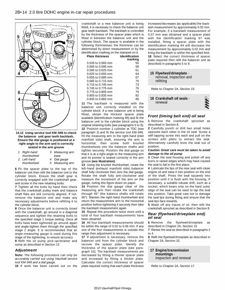
6 Fit the spacer plate to the top of thebalancer unit then refit the balancer unit to thecylinder block. Ensure the shaft gear iscorrectly engaged with the crankshaft gear,and screw in the new retaining bolts.7 Tighten all the bolts by hand then checkthat the crankshaft pulley mark and balanceshaft flats are still correctly aligned. If not,remove the balancer unit and make anynecessary adjustments before refitting it tothe cylinder block.8 Once the balancer unit is correctly timedwith the crankshaft, go around in a diagonalsequence and tighten the retaining bolts tothe specified stage 1 torque setting. Once allbolts have been tightened go around againand angle-tighten them through the specifiedstage 2 angle. It is recommended that anangle-measuring gauge is used during thisstage of the tightening, to ensure accuracy.9 Refit the oil pump pick-up/strainer andsump as described in Section 12.
AdjustmentNote: The following procedure can only beaccurately carried out using Vauxhall servicetool KM-949 and a dial gauge.10 If work has been carried out on the
crankshaft or a new balancer unit is beingfitted, it is necessary to check the balancer unitgear teeth backlash. The backlash is controlledby the thickness of the spacer plate which isfitted in between the balancer unit and thecylinder block. The spacer is available in thefollowing thicknesses; the thickness can bedetermined by direct measurement or by theidentification marking on the stamped on it.
Plate thickness Identificationmarking
0.535 to 0.565 mm 550.565 to 0.595 mm 580.595 to 0.625 mm 610.625 to 0.655 mm 640.655 to 0.685 mm 670.685 to 0.715 mm 700.715 to 0.745 mm 730.745 to 0.775 mm 760.775 to 0.805 mm 790.805 to 0.835 mm 820.835 to 0.865 mm 85
11 The backlash is measured with thebalancer unit correctly installed on thecylinder block. If a new balancer unit is beingfitted, obtain the thickest spacer plateavailable (identification marking 85) and fit thebalancer unit to the cylinder block using theoriginal retaining bolts (see paragraphs 5 to 8).12 Position number 1 cylinder at TDC (seeparagraph 2) and fit the service tool KM-949.Fit the measuring arm to the right-hand (inletmanifold side) shaft, ensuring the arm ishorizontal, then screw both knurledthumbwheels into the balancer shafts andtighten securely. Position the dial gauge sothat it is at a right-angle to the measuring armand its pointer is seated correctly in the armgroove (see illustration).13 Using the knurled thumbwheel, rotate theleft-hand (exhaust manifold side) balancershaft fully clockwise then zero the dial gauge.Rotate the shaft fully anti-clockwise andmeasure the movement of the arm on thegauge, noting this figure down on paper.14 Position the dial gauge clear of themeasuring arm then rotate the crankshaftthrough 45° (the balance shafts will rotate90°). Slacken the right-hand thumbwheel andreturn the measurement arm to the horizontalposition before tightening it securely then takethe backlash measurement again.15 Repeat this procedure twice more until atotal of four backlash measurements havebeen obtained.16 All four backlash measurements shouldbe within the range of 0.02 to 0.06 mm. If anyone of the four measurements is outside thisrange then adjustment is necessary.17 If adjustment is necessary, remove thebalancer unit from the cylinder block andrecover the spacer plate. Identify thethickness of the spacer plate (see para-graph 10). The backlash measurements aredecreased by fitting a thinner spacer plateand increased by fitting a thicker plate.Calculate the correct thickness of spacerplate required noting that each plate thickness
increases/decreases (as applicable) the back-lash measurement by approximately 0.02 mm.For example, if a backlash measurement of0.07 mm was obtained and a spacer platewith the identification marking 67 wasinstalled, fitting a spacer plate with theidentification marking 64 will decrease themeasurement by approximately 0.02 mm andbring the backlash to within the specified limit.18 Select the correct thickness of spacerplate required then refit the balancer unit asdescribed in paragraphs 5 to 9.
15 Flywheel/driveplate -removal, inspection andrefitting
Refer to Chapter 2A, Section 15.
16 Crankshaft oil seals - renewal 4
Front (timing belt end) oil seal1 Remove the crankshaft sprocket asdescribed in Section 8.2 Carefully punch or drill two small holesopposite each other in the oil seal. Screw aself-tapping screw into each and pull on thescrews with pliers to extract the seal.Alternatively carefully lever the seal out ofposition.Caution: Great care must be taken to avoiddamage to the oil pump3 Clean the seal housing and polish off anyburrs or raised edges which may have causedthe seal to fail in the first place.4 Lubricate the lips of the new seal with cleanengine oil and ease it into position on the endof the shaft. Press the seal squarely intoposition until it is flush with the housing. Ifnecessary, a suitable tubular drift, such as asocket, which bears only on the hard outeredge of the seal can be used to tap the sealinto position. Take great care not to damagethe seal lips during fitting and ensure that theseal lips face inwards.5 Wash off any traces of oil, then refit thecrankshaft sprocket as described in Section 8.
Rear (flywheel/driveplate end)oil seal6 Remove the flywheel/driveplate asdescribed in Chapter 2A, Section 15.7 Renew the seal as described in paragraphs 2to 4.8 Refit the flywheel/driveplate as described inChapter 2A, Section 15.
17 Engine/transmissionmountings - inspection and renewal
Refer to Chapter 2A, Section 17.
2B•14 2.0 litre DOHC engine in-car repair procedures
14.12 Using service tool KM-949 to checkthe balancer unit gear teeth backlash.Ensure the dial gauge is positioned at aright-angle to the arm and is correctly
seated in the arm groove
1 Right-handthumbwheel
2 Left-handthumbwheel
3 Measuring armbase
4 Dial gauge5 Measuring arm
3510 Vauxhall/Opel Omega
3510 Vauxhall/Opel Omega
2C•1
2C
Chapter 2 Part C:2.5 and 3.0 litre engine in-car repair procedures
GeneralEngine type . . . . . . . . . . . . . . . . . . . . . . . . . . . . . . . . . . . . . . . . . . . . . . . V6 water-cooled. Double overhead camshaft, belt-driven
2.5 litre engine 3.0 litre engineManufacturer’s engine code . . . . . . . . . . . . . . . . . . . . . . . . . . . . . . . . . . X25XE X30XEBore . . . . . . . . . . . . . . . . . . . . . . . . . . . . . . . . . . . . . . . . . . . . . . . . . . . . 81.6 mm 86.0 mmStroke . . . . . . . . . . . . . . . . . . . . . . . . . . . . . . . . . . . . . . . . . . . . . . . . . . . 79.6 mm 85.0 mmCapacity . . . . . . . . . . . . . . . . . . . . . . . . . . . . . . . . . . . . . . . . . . . . . . . . . 2498 cc 2969 ccMaximum power . . . . . . . . . . . . . . . . . . . . . . . . . . . . . . . . . . . . . . . . . . . 125 kW at 6000 rpm 155 kW at 6200 rpmMaximum torque . . . . . . . . . . . . . . . . . . . . . . . . . . . . . . . . . . . . . . . . . . . 227 Nm at 3200 rpm 270 Nm at 3600 rpmFiring order . . . . . . . . . . . . . . . . . . . . . . . . . . . . . . . . . . . . . . . . . . . . . . . 1-2-3-4-5-6 (No 1 cylinder at timing belt end of right-hand cylinder bank)Direction of crankshaft rotation . . . . . . . . . . . . . . . . . . . . . . . . . . . . . . . Clockwise (viewed from timing belt end of engine)Compression ratio . . . . . . . . . . . . . . . . . . . . . . . . . . . . . . . . . . . . . . . . . 10.8:1
Compression pressuresStandard . . . . . . . . . . . . . . . . . . . . . . . . . . . . . . . . . . . . . . . . . . . . . . . . . 12 to 15 bar (174 to 218 psi)Maximum difference between any two cylinders . . . . . . . . . . . . . . . . . . 1 bar (15 psi)
CamshaftCam lift:
2.5 litre engine . . . . . . . . . . . . . . . . . . . . . . . . . . . . . . . . . . . . . . . . . . 9.2 mm3.0 litre engine . . . . . . . . . . . . . . . . . . . . . . . . . . . . . . . . . . . . . . . . . . 10.0 mm
Lubrication systemOil pump type . . . . . . . . . . . . . . . . . . . . . . . . . . . . . . . . . . . . . . . . . . . . . Rotor-type, driven directly from crankshaftMinimum permissible oil pressure at idle speed, with engine
at operating temperature (oil temperature of at least 80°C) . . . . . . . . 1.5 bar (22 psi)Oil pump rotor endfloat:
Inner rotor . . . . . . . . . . . . . . . . . . . . . . . . . . . . . . . . . . . . . . . . . . . . . . Less than 0.08 mmOuter rotor . . . . . . . . . . . . . . . . . . . . . . . . . . . . . . . . . . . . . . . . . . . . . Less than 0.10 mm
Camshaft covers - removal and refitting . . . . . . . . . . . . . . . . . . . . . . 4Camshaft oil seals - renewal . . . . . . . . . . . . . . . . . . . . . . . . . . . . . . . 9Camshafts and followers - removal, inspection and refitting . . . . . . 10Compression test - description and interpretation . . . . . . . . . . . . . . 2Crankshaft oil seals - renewal . . . . . . . . . . . . . . . . . . . . . . . . . . . . . . 16Crankshaft pulley - removal and refitting . . . . . . . . . . . . . . . . . . . . . . 5Cylinder heads - removal and refitting . . . . . . . . . . . . . . . . . . . . . . . 11Engine oil and filter - renewal . . . . . . . . . . . . . . . . . . . . .See Chapter 1Engine oil level check . . . . . . . . . . . . . . . . . . . . . . .See Weekly checksEngine/transmission mountings - inspection and renewal . . . . . . . . 17
Flywheel/driveplate - removal, inspection and refitting . . . . . . . . . . . 15General information . . . . . . . . . . . . . . . . . . . . . . . . . . . . . . . . . . . . . . 1Oil cooler - removal and refitting . . . . . . . . . . . . . . . . . . . . . . . . . . . . 14Oil pump - removal, overhaul and refitting . . . . . . . . . . . . . . . . . . . . 13Sump - removal and refitting . . . . . . . . . . . . . . . . . . . . . . . . . . . . . . . 12Timing belt - removal and refitting . . . . . . . . . . . . . . . . . . . . . . . . . . . 7Timing belt covers - removal and refitting . . . . . . . . . . . . . . . . . . . . . 6Timing belt sprockets, tensioner and guide pulleys - removal and
refitting . . . . . . . . . . . . . . . . . . . . . . . . . . . . . . . . . . . . . . . . . . . . . . 8Top dead centre (TDC) for No 1 piston - locating . . . . . . . . . . . . . . . 3
Specifications
Contents
Easy, suitable fornovice with littleexperience
Fairly easy, suitablefor beginner withsome experience
Fairly difficult,suitable for competentDIY mechanic
Difficult, suitable forexperienced DIYmechanic
Very difficult,suitable for expert DIYor professional
Degrees of difficulty
54321

Torque wrench settings Nm lbf ftAuxiliary drivebelt tensioner bolts . . . . . . . . . . . . . . . . . . . . . . . . . . . . . . 35 26Baffle plate bolts . . . . . . . . . . . . . . . . . . . . . . . . . . . . . . . . . . . . . . . . . . . 8 6Camshaft bearing cap bolts . . . . . . . . . . . . . . . . . . . . . . . . . . . . . . . . . . 8 6Camshaft cover bolts . . . . . . . . . . . . . . . . . . . . . . . . . . . . . . . . . . . . . . . 8 6Camshaft sensor bolt . . . . . . . . . . . . . . . . . . . . . . . . . . . . . . . . . . . . . . . 8 6Camshaft sprocket bolt:
Stage 1 . . . . . . . . . . . . . . . . . . . . . . . . . . . . . . . . . . . . . . . . . . . . . . . . 50 37Stage 2 . . . . . . . . . . . . . . . . . . . . . . . . . . . . . . . . . . . . . . . . . . . . . . . . Angle-tighten a further 60°Stage 3 . . . . . . . . . . . . . . . . . . . . . . . . . . . . . . . . . . . . . . . . . . . . . . . . Angle-tighten a further 15°
Connecting rod big-end bearing cap bolt:Stage 1 . . . . . . . . . . . . . . . . . . . . . . . . . . . . . . . . . . . . . . . . . . . . . . . . 35 26Stage 2 . . . . . . . . . . . . . . . . . . . . . . . . . . . . . . . . . . . . . . . . . . . . . . . . Angle-tighten a further 45°Stage 3 . . . . . . . . . . . . . . . . . . . . . . . . . . . . . . . . . . . . . . . . . . . . . . . . Angle-tighten a further 15°
Coolant pipe (right-hand)-to-cylinder block bolts . . . . . . . . . . . . . . . . . 20 15Coolant pipe/dipstick tube/engine lifting bracket bolt . . . . . . . . . . . . . . 25 18Coolant pump bolts . . . . . . . . . . . . . . . . . . . . . . . . . . . . . . . . . . . . . . . . 25 18Coolant pump pulley bolts:
Stage 1 . . . . . . . . . . . . . . . . . . . . . . . . . . . . . . . . . . . . . . . . . . . . . . . . 8 6Stage 2 . . . . . . . . . . . . . . . . . . . . . . . . . . . . . . . . . . . . . . . . . . . . . . . . Angle-tighten a further 30°Stage 3 . . . . . . . . . . . . . . . . . . . . . . . . . . . . . . . . . . . . . . . . . . . . . . . . Angle-tighten a further 30°
Crankcase breather housing bolts . . . . . . . . . . . . . . . . . . . . . . . . . . . . . 8 6Crankshaft pulley bolts . . . . . . . . . . . . . . . . . . . . . . . . . . . . . . . . . . . . . . 20 15Crankshaft sensor rotor bolts . . . . . . . . . . . . . . . . . . . . . . . . . . . . . . . . . 15 11Crankshaft sprocket bolt:
Stage 1 . . . . . . . . . . . . . . . . . . . . . . . . . . . . . . . . . . . . . . . . . . . . . . . . 250 185Stage 2 . . . . . . . . . . . . . . . . . . . . . . . . . . . . . . . . . . . . . . . . . . . . . . . . Angle-tighten a further 45°Stage 3 . . . . . . . . . . . . . . . . . . . . . . . . . . . . . . . . . . . . . . . . . . . . . . . . Angle-tighten a further 15°
Cylinder head bolts:Stage 1 . . . . . . . . . . . . . . . . . . . . . . . . . . . . . . . . . . . . . . . . . . . . . . . . 25 18Stage 2 . . . . . . . . . . . . . . . . . . . . . . . . . . . . . . . . . . . . . . . . . . . . . . . . Angle-tighten a further 90°Stage 3 . . . . . . . . . . . . . . . . . . . . . . . . . . . . . . . . . . . . . . . . . . . . . . . . Angle-tighten a further 90°Stage 4 . . . . . . . . . . . . . . . . . . . . . . . . . . . . . . . . . . . . . . . . . . . . . . . . Angle-tighten a further 90°Stage 5 . . . . . . . . . . . . . . . . . . . . . . . . . . . . . . . . . . . . . . . . . . . . . . . . Angle-tighten a further 15°
Cylinder head coolant outlet bolts . . . . . . . . . . . . . . . . . . . . . . . . . . . . . 30 22Driveplate bolts:
Stage 1 . . . . . . . . . . . . . . . . . . . . . . . . . . . . . . . . . . . . . . . . . . . . . . . . 65 48Stage 2 . . . . . . . . . . . . . . . . . . . . . . . . . . . . . . . . . . . . . . . . . . . . . . . . Angle-tighten a further 30°Stage 3 . . . . . . . . . . . . . . . . . . . . . . . . . . . . . . . . . . . . . . . . . . . . . . . . Angle-tighten a further 15°
Engine/transmission mounting bolts:Left- and right-hand mountings:
Mounting-to-subframe nut . . . . . . . . . . . . . . . . . . . . . . . . . . . . . . . 55 41Mounting-to-mounting bracket nut . . . . . . . . . . . . . . . . . . . . . . . . . 40 30Mounting bracket-to-cylinder block bolts . . . . . . . . . . . . . . . . . . . . 60 44Vibration damper bolts . . . . . . . . . . . . . . . . . . . . . . . . . . . . . . . . . . 40 30
Rear mounting:Mounting-to-transmission bolts . . . . . . . . . . . . . . . . . . . . . . . . . . . 40 30Mounting-to-crossmember nuts . . . . . . . . . . . . . . . . . . . . . . . . . . . 20 15Crossmember-to-body bolts . . . . . . . . . . . . . . . . . . . . . . . . . . . . . 45 33
Engine-to-transmission unit bolts:Transmission-to-cylinder block bolts . . . . . . . . . . . . . . . . . . . . . . . . . 60 44Transmission-to-sump flange bolts . . . . . . . . . . . . . . . . . . . . . . . . . . 40 30
Flywheel bolts:Stage 1 . . . . . . . . . . . . . . . . . . . . . . . . . . . . . . . . . . . . . . . . . . . . . . . . 65 48Stage 2 . . . . . . . . . . . . . . . . . . . . . . . . . . . . . . . . . . . . . . . . . . . . . . . . Angle-tighten a further 30°Stage 3 . . . . . . . . . . . . . . . . . . . . . . . . . . . . . . . . . . . . . . . . . . . . . . . . Angle-tighten a further 15°
Main bearing cap/bridge casting:Main bearing cap bolts:
Stage 1 . . . . . . . . . . . . . . . . . . . . . . . . . . . . . . . . . . . . . . . . . . . . . . 50 37Stage 2 . . . . . . . . . . . . . . . . . . . . . . . . . . . . . . . . . . . . . . . . . . . . . . Angle-tighten a further 60°Stage 3 . . . . . . . . . . . . . . . . . . . . . . . . . . . . . . . . . . . . . . . . . . . . . . Angle-tighten a further 15°
Casting threaded sleeves . . . . . . . . . . . . . . . . . . . . . . . . . . . . . . . . . . 8 6Casting-to-cylinder block (M8) bolts . . . . . . . . . . . . . . . . . . . . . . . . . 20 15
Oil cooler:Cover bolts . . . . . . . . . . . . . . . . . . . . . . . . . . . . . . . . . . . . . . . . . . . . . 20 15Cover nuts . . . . . . . . . . . . . . . . . . . . . . . . . . . . . . . . . . . . . . . . . . . . . . 30 22
Oil cooler pipe union nuts and bolts . . . . . . . . . . . . . . . . . . . . . . . . . . . . 30 22
2C•2 2.5 and 3.0 litre engine in-car repair procedures
3510 Vauxhall/Opel Omega

1 General information
How to use this Chapter1 This Part of Chapter 2 is devoted to in-carrepair procedures for the engine. Allprocedures concerning engine removal andrefitting, and engine block/cylinder headoverhaul can be found in Chapter 2D.2 Most of the operations included in this Partare based on the assumption that the engineis still installed in the car. Therefore, if thisinformation is being used during a completeengine overhaul, with the engine alreadyremoved, many of the steps included here willnot apply.
Engine description3 The engine is a double overhead camshaft,V6 unit, mounted at the front of the car withthe transmission on its rear. The cylinderbanks are arranged at a 54° angle to keep theengine as compact as possible. This engine isoften referred to as the V6 ECOTEC engine(Emission Consumption OptimizedTEChnology).
4 The cylinder block is of the dry-liner type.The crankshaft is supported within the cylinderblock on four shell-type main bearings. Thrust-washers are fitted to number 4 (flywheel/driveplate end) main bearing, to control crank-shaft endfloat.5 The aluminium alloy pistons are of theslipper type, and are fitted with three pistonrings, comprising two compression rings anda scraper-type oil control ring. The pistons arejoined to the connecting rods by gudgeonpins; on 2.5 litre engines the pins are aninterference-fit and on 3.0 litre engines thepins are secured in position with circlips. Onall engines, the connecting rods are attachedto the crankshaft by horizontally split shell-type big-end bearings.6 The camshafts run directly in the cylinderheads, and are driven by the crankshaft via atoothed rubber timing belt. The camshaftsoperate each valve via a follower. Eachfollower incorporates a hydraulic self-adjusting valve which automatically adjust thevalve clearances.7 Lubrication is by pressure-feed from arotor-type oil pump, which is mounted on thefront end of the crankshaft. It draws oilthrough a strainer located in the sump, andthen forces it through an externally mounted
full-flow cartridge-type filter. The oil flows intogalleries in the main bearing cap bridgearrangement and cylinder block/crankcase,from where it is distributed to the crankshaft(main bearings) and camshafts. The big-endbearings are supplied with oil via internaldrillings in the crankshaft, while the camshaftbearings also receive a pressurised supply.The camshaft lobes and valves are lubricatedby splash, as are all other enginecomponents. An oil cooler is fitted to helpkeep the oil temperature stable under arduousoperating temperatures; the cooler is fitted tothe top of the cylinder block where it islocated in between the cylinder banks.8 A semi-closed crankcase ventilation systemis employed; crankcase fumes are drawn fromcylinder head cover, and passed via a hose tothe inlet manifold.
Repair operations possible withthe engine in the car9 The following operations can be carried outwithout having to remove the engine from thevehicle.a) Removal and refitting of the cylinder
heads.b) Removal and refitting of the timing belt
and sprockets.
2.5 and 3.0 litre engine in-car repair procedures 2C•3
2C
3510 Vauxhall/Opel Omega
Torque wrench settings (continued) Nm lbf ftOil filter . . . . . . . . . . . . . . . . . . . . . . . . . . . . . . . . . . . . . . . . . . . . . . . . . . 15 11Oil pump cover screws . . . . . . . . . . . . . . . . . . . . . . . . . . . . . . . . . . . . . . 8 6Oil pump retaining bolts - see text for details:
M6 bolts with original timing belt rear cover:Initial torque . . . . . . . . . . . . . . . . . . . . . . . . . . . . . . . . . . . . . . . . . . 8 6Final torque . . . . . . . . . . . . . . . . . . . . . . . . . . . . . . . . . . . . . . . . . . . 10 7
M6 bolts with modified timing belt rear cover . . . . . . . . . . . . . . . . . . 10 7M8 bolts:
Stage 1 . . . . . . . . . . . . . . . . . . . . . . . . . . . . . . . . . . . . . . . . . . . . . . 12 9Stage 2 . . . . . . . . . . . . . . . . . . . . . . . . . . . . . . . . . . . . . . . . . . . . . . 20 15
Oil pump pick-up/strainer bolts . . . . . . . . . . . . . . . . . . . . . . . . . . . . . . . 8 6Power steering pump pulley bolts:
Stage 1 . . . . . . . . . . . . . . . . . . . . . . . . . . . . . . . . . . . . . . . . . . . . . . . . 20 15Stage 2 . . . . . . . . . . . . . . . . . . . . . . . . . . . . . . . . . . . . . . . . . . . . . . . . Angle-tighten a further 30°Stage 3 . . . . . . . . . . . . . . . . . . . . . . . . . . . . . . . . . . . . . . . . . . . . . . . . Angle-tighten a further 15°
Sump bolts:Sump pan bolts:
Stage 1 . . . . . . . . . . . . . . . . . . . . . . . . . . . . . . . . . . . . . . . . . . . . . . 8 6Stage 2 . . . . . . . . . . . . . . . . . . . . . . . . . . . . . . . . . . . . . . . . . . . . . . Angle-tighten a further 30°
Main casting bolts:Casting-to-cylinder block/oil pump bolts . . . . . . . . . . . . . . . . . . . . 15 11Casting flange-to-transmission bolts . . . . . . . . . . . . . . . . . . . . . . . 40 30
Sump drain plug:Hex-head bolt . . . . . . . . . . . . . . . . . . . . . . . . . . . . . . . . . . . . . . . . . . . 55 41Torx-head bolt . . . . . . . . . . . . . . . . . . . . . . . . . . . . . . . . . . . . . . . . . . 10 7
Timing belt cover bolts:Outer cover . . . . . . . . . . . . . . . . . . . . . . . . . . . . . . . . . . . . . . . . . . . . . 8 6Rear cover:
M6 bolts . . . . . . . . . . . . . . . . . . . . . . . . . . . . . . . . . . . . . . . . . . . . . 8 6M8 threaded stud . . . . . . . . . . . . . . . . . . . . . . . . . . . . . . . . . . . . . . 10 7
Timing belt lower guide pulley bolt . . . . . . . . . . . . . . . . . . . . . . . . . . . . . 40 30Timing belt tensioner pulley/upper guide pulley assembly:
Backplate-to-cylinder head bolts . . . . . . . . . . . . . . . . . . . . . . . . . . . . 40 30Tensioner pulley nut . . . . . . . . . . . . . . . . . . . . . . . . . . . . . . . . . . . . . . 20 15Guide pulley bolt . . . . . . . . . . . . . . . . . . . . . . . . . . . . . . . . . . . . . . . . . 40 30

c) Renewal of the camshaft oil seals.d) Removal and refitting of the camshafts
and followers.e) Removal and refitting of the sump.f) Removal and refitting of the connecting
rods and pistons*.g) Removal and refitting of the oil pump.h) Renewal of the crankshaft oil seals.i) Renewal of the engine mountings.j) Removal and refitting of the
flywheel/driveplate.* Although the operation marked with an ast-erisk can be carried out with the engine in thecar after removal of the sump, it is better for theengine to be removed, in the interests of clean-liness and improved access. For this reason,the procedure is described in Chapter 2D.
2 Compression test -description and interpretation
Refer to Chapter 2A, Section 2.
3 Top dead centre (TDC) for No 1 piston -locating
31 In its travel up and down its cylinder bore,Top Dead Centre (TDC) is the highest pointthat each piston reaches as the crankshaftrotates. While each piston reaches TDC bothat the top of the compression stroke andagain at the top of the exhaust stroke, for thepurpose of timing the engine, TDC refers tothe piston position (usually number 1) at thetop of its compression stroke.2 Number 1 piston (and cylinder) is at thefront (timing belt) end of the right-handcylinder bank, and its TDC position is locatedas follows. Note that the crankshaft rotatesclockwise when viewed from the front of thevehicle.
3 Disconnect the battery negative terminal. Ifnecessary, remove all the spark plugs asdescribed in Chapter 1 to enable the engine tobe easily turned over.4 Remove the timing belt outer cover to gainaccess to the camshaft sprocket timing marks(see Section 6).5 Using a socket and extension bar on thecrankshaft sprocket bolt, rotate the crankshaftuntil the relevant timing marks on thecamshaft sprockets are all at the top and arecorrectly aligned with the marks on the timingbelt rear cover. Each sprocket has two timingmarks the correct mark to use is as follows(see illustrations).
Camshaft Timing mark to be usedRight-hand cylinder head exhaust 1Right-hand cylinder head inlet 2Left-hand cylinder head inlet 3Left-hand cylinder head exhaust 4
6 With the camshaft sprocket marks correctlypositioned, align the notch on the crankshaftpulley rim with the pointer on the oil pumphousing (see illustration). The engine is nowpositioned with No1 piston at TDC on itscompression stroke. Note: If the crankshaft
pulley has been removed, use the mark on thecrankshaft sprocket rim. The mark should bealigned with the cutout on the base of the oilpump housing (see Section 7).
4 Camshaft covers - removal and refitting 3
Removal1 Remove the inlet manifold as described inChapter 4A.
Right-hand cover2 Disconnect the plug caps from the plugsthen unclip the HT leads and position themclear of the cover.3 Evenly and progressively slacken andremove the camshaft cover retaining bolts.4 Lift the camshaft cover away from thecylinder head and recover the cover seals andthe sealing rings which are fitted to each ofthe retaining bolt holes. Examine the seal andsealing rings for signs of wear or damage andrenew if necessary.
Left-hand cover5 To improve access, remove the windscreenwiper arms and the water deflector panel (seeChapter 12, Sections 15 and 16). Access canbe further improved by disconnecting theengine wiring harness as described inparagraphs 14 to 16 of Section 11 andpositioning it clear of the cover.6 On models with air conditioning, unbolt theair conditioning pipe/hose bracket from thefront of the cylinder head and position thehose/pipe to one side.7 Lift the oil filler neck retaining tab then twistthe neck anti-clockwise and remove it fromthe top of the cover (see illustrations).Recover the neck sealing ring and discard it; anew one should be used on refitting.
2C•4 2.5 and 3.0 litre engine in-car repair procedures
3.6 . . . and the crankshaft pulley notchwith the pointer on the oil pump housing
(arrowed) to position No1 piston at TDC onits compression stroke
3510 Vauxhall/Opel Omega
3.5a Align the relevant camshaft sprockets timing marks with thecutouts on the timing belt rear cover (arrowed) on both the right-
hand . . .
3.5b . . . and left-hand cylinder heads (arrowed) . . .
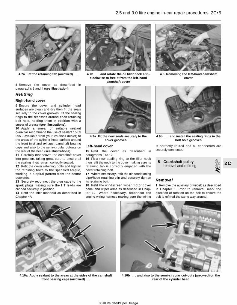
8 Remove the cover as described inparagraphs 3 and 4 (see illustration).
Refitting
Right-hand cover9 Ensure the cover and cylinder headsurfaces are clean and dry then fit the sealssecurely to the cover grooves. Fit the sealingrings to the recesses around each retainingbolt hole, holding them in position with asmear of grease (see illustrations).10 Apply a smear of suitable sealant(Vauxhall recommend the use of sealant 15 03295 - available from your Vauxhall dealer) tothe areas of the cylinder head surface aroundthe front inlet and exhaust camshaft bearingcaps and also to the semi-circular cutouts onthe rear of the head (see illustrations).11 Carefully manoeuvre the camshaft coverinto position, taking great care to ensure allthe sealing rings remain correctly seated.12 Refit the cover retaining bolts and tightenthe retaining bolts to the specified torque,working in a spiral pattern from the centreoutwards.13 Securely reconnect the plug caps to thespark plugs making sure the HT leads areclipped securely in position.14 Refit the inlet manifold as described inChapter 4A.
Left-hand cover15 Refit the cover as described inparagraphs 9 to 12.16 Fit a new sealing ring to the filler neckthen refit the neck to the cover making sure itsretaining tab is correctly engaged with thecover retaining bolt.17 Where necessary, refit the air conditioningpipe/hose retaining clip and securely tightenits retaining bolt.18 Refit the windscreen wiper motor coverpanel and wiper arms as described in Chap-ter 12. Where necessary, reconnect theengine wiring harness making sure the wiring
is correctly routed and all connectors aresecurely connected.
5 Crankshaft pulley - removal and refitting 2
Removal1 Remove the auxiliary drivebelt as describedin Chapter 1. Prior to removal, mark thedirection of rotation on the belt to ensure thebelt is refitted the same way around.
2.5 and 3.0 litre engine in-car repair procedures 2C•5
2C
4.7a Lift the retaining tab (arrowed) . . . 4.7b . . . and rotate the oil filler neck anti-clockwise to free it from the left-hand
camshaft cover
4.8 Removing the left-hand camshaftcover
4.9b . . . and install the sealing rings in thebolt hole grooves
4.9a Fit the new seals securely to thecover grooves . . .
3510 Vauxhall/Opel Omega
4.10a Apply sealant to the areas at the sides of the camshaftfront bearing caps (arrowed) . . .
4.10b . . . and also to the semi-circular cut-outs (arrowed) on therear of the cylinder head

2 Using a socket and extension bar on thecrankshaft sprocket bolt, turn the crankshaftuntil the notch on the pulley rim is correctlyaligned with the pointer on the cover.3 Slacken and remove the small retainingbolts securing the pulley to the crankshaftsprocket and remove the pulley from theengine. If necessary, prevent crankshaftrotation by holding the sprocket retaining boltwith a suitable socket.
Refitting4 Check that the crankshaft sprocket mark isstill aligned with the mark on the oil pumphousing then manoeuvre the crankshaft pulleyinto position. Align the notch on the pulley rimwith the pointer then seat the pulley on thesprocket and tighten its retaining bolts to thespecified torque.
5 Refit the auxiliary drivebelt as described inChapter 1 using the mark made prior toremoval to ensure the belt is fitted the correctway around.
6 Timing belt covers - removal and refitting 4
Outer coverNote: New coolant pump and power steeringpump pulley bolts will be required on refitting.
Removal1 Remove the multi-ram air intake systempre-volume chamber assembly as describedin Chapter 4A.
2 Remove the secondary air injection systemfront connecting pipe as described in Chap-ter 4B.3 Remove the auxiliary drivebelt as describedin Chapter 1. Prior to removal, mark thedirection of rotation on the belt to ensure thebelt is refitted the same way around.4 Slacken and remove the coolant pumpdrivebelt pulley retaining bolts whilst retainingthe pump shaft with an open-ended spanner.Remove the pulley and discard the bolts; newones must be used on refitting (seeillustrations).5 Insert a socket and extension bar in throughthe one of the power steering pump pulleyholes and locate it on a pump mounting boltto prevent rotation. Slacken and remove thepulley retaining bolts and remove the pulley,noting which way around it is fitted (seeillustrations). Discard the bolts; new onesmust be used on refitting.6 Disconnect the right-hand cylinder bankknock sensor wiring connector and unclip itfrom the front of the timing belt cover.7 Unclip the covers from the front and right-hand end of the wiring harness tray whichruns across the front of the timing belt cover.Disconnect the wiring connector from theEGR valve and position the wiring harnessclear of the timing belt cover then undo theretaining bolts and remove the tray from thebelt cover (see illustrations).8 Slacken and remove the retaining bolts andremove the auxiliary drivebelt tensionerassembly from the right-hand cylinder head(see illustration).
2C•6 2.5 and 3.0 litre engine in-car repair procedures
6.4a Retain the coolant pump shaft withan open-ended spanner then undo the
retaining bolts . . .
6.4b . . . and remove the pulley from theengine
6.5a Insert a socket and extension barthrough the power steering pump pulley
then undo the retaining bolts . . .
6.7b . . . and right-hand covers andposition the wiring harness clear of the
tray
6.7c Undo the retaining bolts and removethe tray from the timing belt cover
6.5b . . . and remove the pulley from thepump
6.7a Unclip the front . . .
6.8 Undo the retaining bolts and removethe auxiliary drivebelt tensioner
3510 Vauxhall/Opel Omega
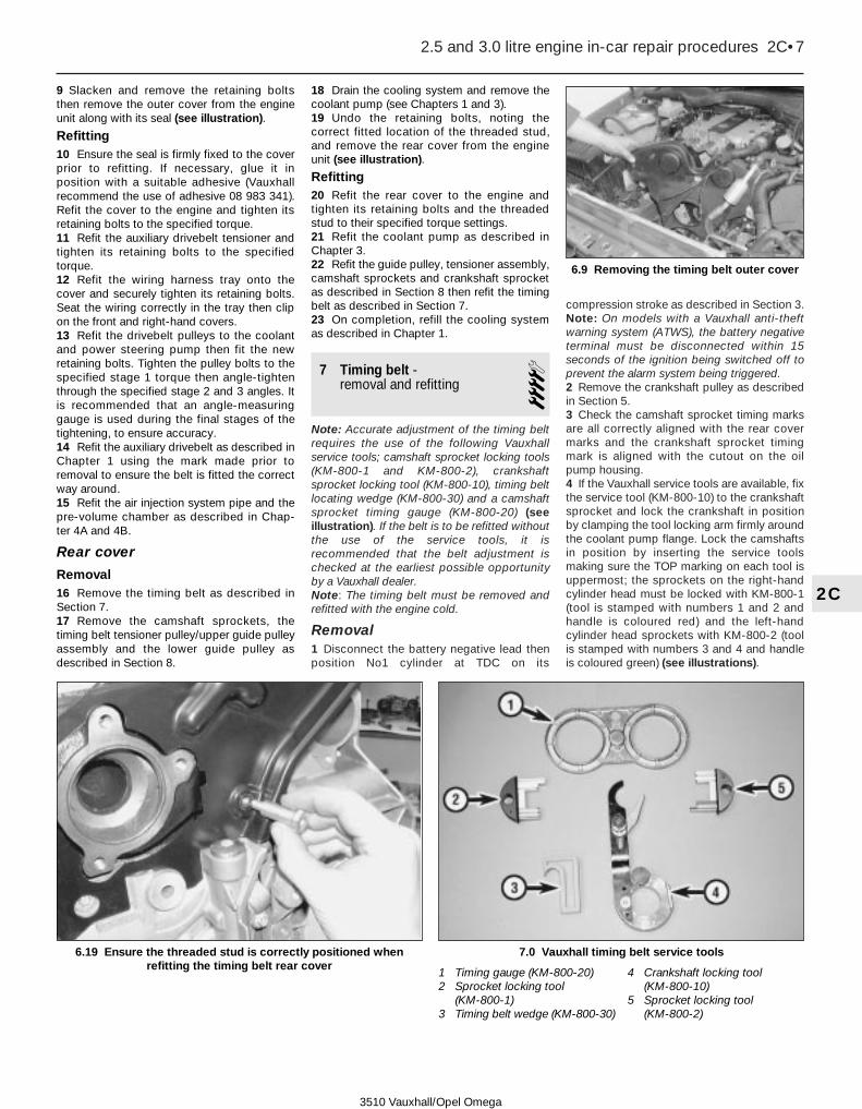
9 Slacken and remove the retaining boltsthen remove the outer cover from the engineunit along with its seal (see illustration).
Refitting10 Ensure the seal is firmly fixed to the coverprior to refitting. If necessary, glue it inposition with a suitable adhesive (Vauxhallrecommend the use of adhesive 08 983 341).Refit the cover to the engine and tighten itsretaining bolts to the specified torque.11 Refit the auxiliary drivebelt tensioner andtighten its retaining bolts to the specifiedtorque.12 Refit the wiring harness tray onto thecover and securely tighten its retaining bolts.Seat the wiring correctly in the tray then clipon the front and right-hand covers.13 Refit the drivebelt pulleys to the coolantand power steering pump then fit the newretaining bolts. Tighten the pulley bolts to thespecified stage 1 torque then angle-tightenthrough the specified stage 2 and 3 angles. Itis recommended that an angle-measuringgauge is used during the final stages of thetightening, to ensure accuracy.14 Refit the auxiliary drivebelt as described inChapter 1 using the mark made prior toremoval to ensure the belt is fitted the correctway around.15 Refit the air injection system pipe and thepre-volume chamber as described in Chap-ter 4A and 4B.
Rear cover
Removal16 Remove the timing belt as described inSection 7.17 Remove the camshaft sprockets, thetiming belt tensioner pulley/upper guide pulleyassembly and the lower guide pulley asdescribed in Section 8.
18 Drain the cooling system and remove thecoolant pump (see Chapters 1 and 3).19 Undo the retaining bolts, noting thecorrect fitted location of the threaded stud,and remove the rear cover from the engineunit (see illustration).
Refitting20 Refit the rear cover to the engine andtighten its retaining bolts and the threadedstud to their specified torque settings.21 Refit the coolant pump as described inChapter 3.22 Refit the guide pulley, tensioner assembly,camshaft sprockets and crankshaft sprocketas described in Section 8 then refit the timingbelt as described in Section 7.23 On completion, refill the cooling systemas described in Chapter 1.
7 Timing belt - removal and refitting 4
Note: Accurate adjustment of the timing beltrequires the use of the following Vauxhallservice tools; camshaft sprocket locking tools(KM-800-1 and KM-800-2), crankshaftsprocket locking tool (KM-800-10), timing beltlocating wedge (KM-800-30) and a camshaftsprocket timing gauge (KM-800-20) (seeillustration). If the belt is to be refitted withoutthe use of the service tools, it isrecommended that the belt adjustment ischecked at the earliest possible opportunityby a Vauxhall dealer.Note: The timing belt must be removed andrefitted with the engine cold.
Removal1 Disconnect the battery negative lead thenposition No1 cylinder at TDC on its
compression stroke as described in Section 3.Note: On models with a Vauxhall anti-theftwarning system (ATWS), the battery negativeterminal must be disconnected within 15seconds of the ignition being switched off toprevent the alarm system being triggered.2 Remove the crankshaft pulley as describedin Section 5.3 Check the camshaft sprocket timing marksare all correctly aligned with the rear covermarks and the crankshaft sprocket timingmark is aligned with the cutout on the oilpump housing.4 If the Vauxhall service tools are available, fixthe service tool (KM-800-10) to the crankshaftsprocket and lock the crankshaft in positionby clamping the tool locking arm firmly aroundthe coolant pump flange. Lock the camshaftsin position by inserting the service toolsmaking sure the TOP marking on each tool isuppermost; the sprockets on the right-handcylinder head must be locked with KM-800-1(tool is stamped with numbers 1 and 2 andhandle is coloured red) and the left-handcylinder head sprockets with KM-800-2 (toolis stamped with numbers 3 and 4 and handleis coloured green) (see illustrations).
2.5 and 3.0 litre engine in-car repair procedures 2C•7
2C
6.9 Removing the timing belt outer cover
3510 Vauxhall/Opel Omega
7.0 Vauxhall timing belt service tools
1 Timing gauge (KM-800-20)2 Sprocket locking tool
(KM-800-1)3 Timing belt wedge (KM-800-30)
4 Crankshaft locking tool (KM-800-10)
5 Sprocket locking tool (KM-800-2)
6.19 Ensure the threaded stud is correctly positioned whenrefitting the timing belt rear cover
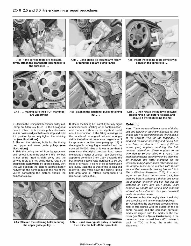
5 Slacken the timing belt tensioner pulley nut.Using an Allen key fitted to the hexagonalcutout, rotate the tensioner pulley clockwiseso it is positioned just before its stop and holdit in position by securely tighten the retainingnut (see illustrations).6 Slacken the retaining bolts for the timingbelt upper and lower guide pulleys (seeillustrations).7 Slide the timing belt off from its sprocketsand remove it from the engine. If the new beltis not being fitted straight away and theservice tools are not being used, rotate thecrankshaft backwards by approximately 60°;this will position the pistons approximatelyhalfway up the bores reducing the risk of thevalves contacting the pistons should thecamshafts move.
8 Check the timing belt carefully for any signsof uneven wear, splitting or oil contamination,and renew it if there is the slightest doubtabout its condition. If the fitting markings onthe outside of the original belt are no longervisible the belt must be renewed regardless ofits apparent condition (see paragraph 12). Ifthe engine is undergoing an overhaul and hascovered 40 000 miles or it was more than 4years since the original belt was fitted, renewthe belt as a matter of course, regardless of itsapparent condition (from 1997 onwards thebelt renewal interval was increased to 80 000miles or 8 years). If signs of oil contaminationare found, trace the source of the oil leak andrectify it, then wash down the engine timingbelt area and all related components toremove all traces of oil.
RefittingNote: There are two different types of timingbelt and tensioner assembly available for thisengine and it is essential that the timing belt isof the correct type for the tensioner. Amodified tensioner assembly and timing beltwere fitted as standard to later (1997 onmodel year) engines, enabling the beltrenewal interval on these engines to beextended to 80 000 miles or 8 years. Themodified tensioner assembly can be identifiedby checking the letter stamped on thetensioner pulley/upper guide roller backplate;the original tensioner is marked with D andthe modified assembly marking has an E in it(EA or EB) (see illustration 7.15). It is mostimportant to check the tensioner backplatemarking before ordering a timing belt sincethe modified tensioner and belt can also beinstalled on early (pre 1997 model year)engines to enable the timing belt renewalinterval to be extended. See your Vauxhalldealer for further details.9 On reassembly, thoroughly clean the timingbelt sprockets and tensioner/guide pulleys.10 Check that the crankshaft sprocket timingmark is still aligned with the cutout on the oilpump housing and the camshaft sprocketmarks are aligned with the marks on the rearcover (see Section 3) (see illustrations). If thecrankshaft was moved back 60°, rotate itback to TDC to bring the marks intoalignment.
2C•8 2.5 and 3.0 litre engine in-car repair procedures
7.4a If the service tools are available,firmly attach the crankshaft locking tool to
the sprocket . . .
7.4b . . . and clamp its locking arm firmlyaround the coolant pump flange
7.4c Insert the locking tools correctly inbetween the sprockets . . .
7.6a Slacken the retaining bolts securingthe upper guide pulley . . .
7.6b . . . and lower guide pulley in positionthen slide the belt off the sprockets
7.4d . . . making sure their TOP markingsare uppermost
7.5a Slacken the tensioner pulley retainingnut . . .
7.5b . . . then rotate the pulley clockwise,positioning it just before its stop, and
secure it by retightening the nut
3510 Vauxhall/Opel Omega

11 If the special tools are available lock thecamshaft sprockets and crankshaft sprocketin position as described in paragraph 4.12 Examine the fitting marks on the outerface of the timing belt. The arrows on the beltmust point in the direction of rotation and thedouble line on the belt should be aligned withthe crankshaft sprocket mark. The four singlelines on the belt will then align with thecamshaft sprocket timing marks if the belt iscorrectly installed.13 Ensure the arrows on the belt are pointingin the correct direction of rotation then alignthe double line on the belt with the crankshaftsprocket timing mark and engage the beltwith the sprocket. If the locating wedge (KM-800-30) is available secure the belt in positionby inserting the wedge in between the right-hand side of the belt and the rear cover (seeillustrations).14 Check the identification marking stampedonto the tensioner pulley/upper guide pulleybackplate (see Note at the start of the refittingprocedure).15 On early engines with the originaltensioner (marked with a D - see illustration),fit the timing belt over the lower guide pulleythen around the left-hand cylinder head
camshaft sprockets making sure the beltfitting marks are correctly aligned with thesprocket marks. Fit the belt around the upperguide pulley then over the right-hand cylindercamshaft, again making sure the fitting marksare correctly aligned and tensioner pulley. Donot twist the belt sharply while refitting it.16 On all engines fitted with the modifiedtensioner (marked with an E - see illustration7.15), fit the belt behind the tensioner pulley
and then over the right-hand cylinder headcamshaft sprockets ensuring that the fittingmarks are both correctly aligned with thesprocket marks. Fit the belt around the upperguide pulley then over the left-hand cylindercamshaft sprockets, again making sure thefitting marks are correctly aligned, and finallyover the lower guide pulley (seeillustrations). Do not twist the belt sharplywhile refitting it.
2.5 and 3.0 litre engine in-car repair procedures 2C•9
2C7.10c . . . and the crankshaft sprockettiming mark is correctly aligned with the oil
pump housing cutout (arrowed)
7.13a Align the double line on the timingbelt with the crankshaft sprocket
timing mark
7.13b If the service tool is available securethe belt in position with the wedge
7.15 Checking the marking (locationarrowed) on the tensioner/upper guide
pulley backplate to identify which type oftensioner assembly is fitted to your engine
- see text
7.16a On engines with a modifiedtensioner, work around in a clockwise
direction and engage the belt first with theright-hand cylinder head sprockets . . .
3510 Vauxhall/Opel Omega
7.10a Ensure the right-hand cylinder head camshaft sprocketmarkings (1 and 2) . . .
7.10b . . . and the left-hand cylinder head camshaft markings (3 and 4) are all correctly aligned with the rear cover cutouts
(arrowed) . . .

17 On all engines, ensure that the belt teethare correctly seated centrally in the sprocketsand the sprocket timing marks/belt fittingmarks are correctly aligned. If adjustment isnecessary, disengage the belt from thesprockets and make any necessaryadjustments.
18 Slacken the lower guide pulley retainingbolt. Rotate the pulley anti-clockwise toremove all slack from the left-hand run of thebelt without placing any excess strain on thebelt. Ensure that all the sprocket timing marksremain in alignment as the pulley is moved; ifthe service tools are available, remove thelocking tools and use the timing gauge (KM-800-20) to check the sprocket mark positions.Once the pulley is correctly positioned, hold itstationary and tighten its retaining bolt to thespecified torque (see illustrations).19 Slacken the upper guide pulley retainingbolt. Rotate the pulley anti-clockwise toremove all slack from the top run of the beltwithout placing any excess strain on the belt.Ensure that all the sprocket timing marksremain in alignment as the pulley is moved.Once the pulley is correctly positioned, hold itstationary and tighten its retaining bolt to thespecified torque (see illustration).20 Slacken the timing belt tensioner pulleynut then, using an Allen key, rotate thetensioner arm anti-clockwise until the gap
between the tensioner plate and its stop is 0.5to 1.5 mm (see illustration). Hold thetensioner pulley in this position and securelytighten its retaining nut.21 Remove all the service tools (where fitted)then using a socket on the crankshaftsprocket bolt, rotate the crankshaft smoothlythrough two complete turns (720°) in thenormal direction of rotation to settle the timingbelt in position.22 Check that all the camshaft andcrankshaft sprocket timing marks arecorrectly realigned then slacken the tensionernut again. Note: The belt fitting lines will notbe realigned with the sprocket marks; theyserve no purpose once the belt has beeninstalled.23 Using an Allen key, position the tensionerpulley so that the index mark on the tensionerplate is positioned 3 to 4 mm above the markon the backplate stop (see illustration). Holdthe tensioner correctly in position and tightenits retaining nut to the specified torque.24 Rotate the crankshaft smoothly through
2C•10 2.5 and 3.0 litre engine in-car repair procedures
7.18b . . . then hold the pulley stationaryand tighten its retaining bolt to the
specified torque
7.18a Remove all slack from the left-handrun of the belt by rotating the lower guide
pulley whilst making sure the sprockettiming marks remain in alignment (timing
gauge shown) . . .
7.19 Remove all slack from the top run ofthe belt then hold the upper pulley
stationary and tighten its retaining bolt tothe specified torque
7.20 Rotate the tensioner pulley anti-clockwise until the gap (arrowed) is 0.5 to1.5 mm then securely tighten its retaining
nut
3510 Vauxhall/Opel Omega
7.16b . . . and then the left-hand head sprockets (directionalfitting arrows arrowed), making sure the fitting lines are all
correctly aligned with the sprockets . . .
7.16c . . . and finally over the lower guide pulley

another two complete turns (720°) in thenormal direction of rotation to bring thesprocket timing marks back into alignment.25 If the service tools are available, lock thecrankshaft in position (KM-800-10) and checkthe camshaft sprocket timing marks arecorrectly positioned using the timing gauge(KM-800-20).26 If the service tools are not available,ensure the crankshaft sprocket timing mark iscorrectly aligned with the cutout on the oilpump housing and all the camshaft sprockettiming marks are exactly aligned with thecutouts on the rear cover.27 If adjustment is necessary repeat theoperations described in paragraphs 18 to 26.28 Once the timing marks are all correctlyaligned, refit the timing belt cover andcrankshaft pulley as described in Sections 5and 6. Note: If refitting has been carried outwithout the use of the service tools, it isadvisable to have the belt adjustment checkedby a Vauxhall dealer at the earliest possibleopportunity.
8 Timing belt sprockets,tensioner and guide pulleys -removal and refitting
4Camshaft sprocketsNote: New sprocket retaining bolt(s) will berequired on refitting.
Removal1 Remove the timing belt as described inSection 7. Once the belt has been removed,rotate the crankshaft backwards byapproximately 60°; this will position thepistons approximately halfway up the boresreducing the risk of the valves contacting thepistons.2 The camshaft must be prevented fromturning as the sprocket bolt is unscrewed, andthis can be achieved in one of two ways.a) Make up a sprocket-holding tool using
two lengths of steel strip (one long, theother short), and three nuts and bolts; one
nut and bolt forms the pivot of a forkedtool, with the remaining two nuts andbolts at the tips of the ‘forks’ to engagewith the sprocket spokes (seeillustration).
b) Remove the camshaft cover as describedin Section 4 and hold the camshaft withan open-ended spanner on the flatsprovided (see illustration).
3 Unscrew the retaining bolt and washer andremove the sprocket from the end of thecamshaft (see illustrations). If the sprocketlocating pin is a loose fit in the camshaft end,remove it and store it with the sprocket forsafe-keeping.4 If necessary, remove the remainingsprocket(s) using the same method.
Refitting5 Prior to refitting check the oil seal(s) forsigns of damage or leakage. If necessary,renew as described in Section 9.6 Ensure the locating pin is in position in thecamshaft end.
2.5 and 3.0 litre engine in-car repair procedures 2C•11
2C
8.2b If the camshaft cover has beenremoved, the camshaft can be held with anopen-ended spanner on the flats provided
8.3a Unscrew the retaining bolt andwasher . . .
8.3b . . . and remove the sprocket from thecamshaft
3510 Vauxhall/Opel Omega
7.23 Adjust the tensioner pulley so that its index mark (A) ispositioned 3 to 4 mm above backplate mark (B) then tighten its
retaining nut to the specified torque
8.2a Using a home-made tool to prevent rotation as the camshaftsprocket bolt is slackened

7 Note that there are two pairs of camshaftsprockets, one for the right-hand cylinderhead and the other for the left-hand cylinderhead; the right-hand cylinder head sprocketscarry the identification marks 1 and 2 and theleft-hand cylinder head sprockets the marks 3and 4. The inlet and exhaust camshaft
sprockets on each head are the same buteach one is equipped with two locating pincutouts and two timing marks. On refitting isvital that the sprocket locating pin is engagedin the correct sprocket slot as follows and thecorrect timing mark is used (seeillustrations).
Camshaft Sprocket slot/timingmark number to be used
Right-hand cylinder head exhaust 1Right-hand cylinder head inlet 2Left-hand cylinder head inlet 3Left-hand cylinder head exhaust 4
8 Ensure the camshaft locating pin is engagedin the correct sprocket cutout then fit the washerand new retaining bolt (see illustrations).9 Retain the sprocket by the method used onremoval, and tighten the sprocket retaining boltto the specified stage 1 torque setting thenangle-tighten the bolt through the specifiedstage 2 angle, using a socket and extensionbar, and finally through the specified stage 3angle (see illustrations). It is recommendedthat an angle-measuring gauge is used duringthe final stages of the tightening, to ensureaccuracy. If a gauge is not available, use whitepaint to make alignment marks between thebolt head and sprocket prior to tightening; themarks can then be used to check that the bolthas been rotated through the correct angle.
2C•12 2.5 and 3.0 litre engine in-car repair procedures
8.9b . . . and then through the specifiedstage 2 and 3 angles
8.9a Retaining the sprocket/camshaft thentighten the retaining bolt first to the stage
1 torque . . .
3510 Vauxhall/Opel Omega
8.7a Right-hand cylinder head camshaft sprocket. Ensure timingmark and slot 1 are used on the exhaust camshaft and 2 on the
inlet camshaft
8.7b Left-hand cylinder head camshaft sprocket. Ensure timingmark and slot 3 are used on the inlet camshaft and 4 on the
exhaust camshaft
8.8a Ensure the locating pins are engaged in the correct sprocketslots (arrowed) . . .
8.8b . . . and the relevant sprocket timing marks are correctlyaligned with the rear cover cutouts (arrowed)

10 Ensure the relevant camshaft sprockettiming marks are all correctly aligned with thecutouts on the rear cover then carefully rotatethe crankshaft in the normal direction ofrotation until the sprocket mark is correctlyrealigned with the notch on the oil pumphousing.11 Refit the timing belt as described inSection 7 then (where necessary) refit thecamshaft cover as described in Section 4.
Crankshaft sprocketNote: A new crankshaft sprocket retainingbolt will be required on refitting.
Removal12 Remove the timing belt as described inSection 7.13 The crankshaft must be prevented fromturning as the sprocket bolt is unscrewed (thebolt is very tight), and this can be achieved inanyone of the following ways.a) Use the holding tool described in
paragraph 2 securing the tool to thesprocket with two bolts screwed intoopposite pulley retaining bolt holes (seeillustration).
b) On manual transmission models have anassistant select top gear and apply thebrakes firmly.
c) If the engine is removed from the vehicleor the transmission unit has beenremoved the flywheel/driveplate can belocked (see Section 15).
14 Unscrew the retaining bolt and removethe crankshaft sprocket from the end of the
crankshaft. Discard the bolt; a new one mustbe used on refitting. If necessary, slide thespacer out from the oil seal and remove itfrom the crankshaft; if the outer surface of thespacer is damaged it should be renewed (seeillustrations).
Refitting15 Prior to refitting, examine the oil seal forsigns of damage or deterioration and renew ifnecessary (see Section 16).16 Slide the spacer (where removed) onto thecrankshaft and into position taking care not todamage the oil seal lip.17 Align the sprocket with the crankshaft slotand slide it into position, ensuring thesprocket flange is facing outwards. Fit thenew retaining bolt.18 Lock the crankshaft by the method usedon removal, and tighten the sprocket retainingbolt to the specified stage 1 torque settingthen angle-tighten the bolt through thespecified stage 2 angle, using a socket andextension bar, and finally through thespecified stage 3 angle. It is recommendedthat an angle-measuring gauge is used duringthe final stages of the tightening, to ensureaccuracy (see illustrations). If a gauge is notavailable, use white paint to make alignmentmarks between the bolt head and sprocketprior to tightening; the marks can then beused to check that the bolt has been rotatedthrough the correct angle.19 Refit the timing belt as described inSection 7.
Tensioner pulley/upper guide pulley assemblyNote: The tensioner pulley/upper guide pulleyassembly must be renewed as a completeunit. It is not possible to renew the individualcomponents of the assembly separately.
Removal20 Remove the timing belt as described inSection 7.21 Slacken and remove the retaining boltssecuring the backplate to the cylinder headand remove the assembly from the engine(see illustrations).
Refitting22 Fit the tensioner pulley/upper guide pulleyassembly to the cylinder head and tighten itsretaining bolts to the specified torque.
2.5 and 3.0 litre engine in-car repair procedures 2C•13
2C
8.13 Home-made tool for preventingcrankshaft rotation as the sprocket bolt is
slackened
8.14a Unscrew the retaining bolt . . . 8.14b . . . then slide off the crankshaftsprocket . . .
8.18a Tighten the crankshaft sprocket boltto the specified stage 1 torque setting . . .
8.18b . . . then tighten it through thespecified stage 2 and 3 angles
8.14c . . . and, if necessary, withdraw thespacer from the oil seal
8.21a Undo the retaining bolts (arrowed) . . .
3510 Vauxhall/Opel Omega

23 Refit the timing belt as described inSection 7. If a new tensioner assembly hasbeen fitted, fit a new timing belt ensuring it isof the correct type for the tensioner.
Lower guide pulley
Removal24 Remove the timing belt as described inSection 7.25 Slacken and remove the retaining bolt andremove the lower guide pulley and its spacerfrom the engine (see illustration).
Refitting26 Position the spacer behind the guidepulley then refit the pulley retaining bolt,tightening it lightly only at this stage.27 Refit the timing belt as described inSection 7.
9 Camshaft oil seals - renewal 4
1 Remove the relevant camshaft sprocket asdescribed in Section 8.2 Carefully punch or drill two small holesopposite each other in the oil seal. Screw aself-tapping screw into each, and pull on thescrews with pliers to extract the seal (seeillustrations). Alternatively carefully lever theoil seal out of position.3 Clean the seal housing, and polish off anyburrs or raised edges which may have causedthe seal to fail in the first place.4 Lubricate the lips of the new seal with cleanengine oil, and press it into position using asuitable tubular drift (such as a socket) whichbears only on the hard outer edge of the seal(see illustration). Take care not to damagethe seal lips during fitting; note that the seallips should face inwards.5 Refit the camshaft sprocket as described inSection 8.
10 Camshafts and followers -removal, inspection andrefitting
4Removal1 Remove the camshaft cover as described inSection 4.
2 Remove the camshaft sprockets asdescribed in Section 8. If the right-handcylinder head camshafts are to be removed,rotate both the inlet and exhaust camshaftbackwards approximately 60°; this willminimise the valve spring pressure beingexerted on the bearing caps and so lessen therisk of damage as the caps are removed. Theleft-hand cylinder head camshafts are bestleft positioned at TDC.3 Starting on the inlet camshaft, working in aspiral pattern from the outside inwards,slacken the camshaft bearing cap retainingbolts by half-a-turn at a time, to relieve thepressure of the valve springs on the bearingcaps gradually and evenly. Once the valvespring pressure has been relieved, the boltscan be fully unscrewed and removed alongwith the caps. The bearing caps and thecylinder head locations are numbered toensure the caps are correctly positioned onrefitting; an identification letter is alsostamped on each cap (see illustration).Caution: If the bearing cap bolts arecarelessly slackened, the bearing capsmight break. If any bearing cap breaksthen the complete cylinder head assemblymust be renewed; the bearing caps arematched to the head and are not availableseparately.4 Lift the camshaft out of the cylinder headand slide off the oil seal. Using a dab of paintor a suitable marker pen, make anidentification mark on the inlet camshaft toavoid getting the camshafts mixed up onrefitting; the inlet and exhaust camshafts arethe same but it is important they are notinterchanged as this will increase the rate ofwear.5 Repeat the operations described inparagraphs 3 and 4 and remove the exhaustcamshaft. If the work is being carried out onthe left-hand cylinder head, prior to removingthe bearing caps, unbolt the camshaft sensor(see Chapter 4A, Section 14) and position itclear of the front bearing cap and free theknock sensor wiring.6 Obtain twelve small, clean plasticcontainers, and label them for identification.Alternatively, divide a larger container intocompartments. Lift the followers out from the
2C•14 2.5 and 3.0 litre engine in-car repair procedures
9.2a Carefully drill/punch holes in the oilseal . . .
9.4 Tap the new seal into position using asocket which bears only on the seal outer
edge as a drift
9.2b . . . then screw in a self-tappingscrew and pull out the oil seal with
pliers/grips
10.3 Prior to removal note theidentification markings on the camshaft
caps and cylinder head (arrowed)
8.21b . . . and remove the tensionerpulley/upper guide pulley assembly from
the cylinder head
8.25 Unscrew the retaining bolt andremove the lower guide pulley and its
spacer (arrowed) from the engine
3510 Vauxhall/Opel Omega

top of the cylinder head and store each one inits respective fitted position (see illustration).Note: Store all the followers the correct wayup to prevent the oil draining from thehydraulic valve adjustment mechanisms.7 If necessary, repeat the operationsdescribed in paragraphs 1 to 6 and removethe camshafts and followers from the othercylinder head. If all the camshafts are to beremoved at the same time, make identificationmarks on the shafts to ensure they are refittedin their original locations, and note thecamshaft bearing caps identification letterlocations to ensure the caps are refitted to thecorrect cylinder head.
Inspection8 Examine the camshaft bearing surfaces andcam lobes for signs of wear ridges and scoring.Renew the camshaft if any of these conditionsare apparent. Examine the condition of thebearing surfaces both on the camshaft journalsand in the cylinder head. If the head bearingsurfaces are worn excessively, the cylinderhead will need to be renewed.9 Examine the follower bearing surfaceswhich contact the camshaft lobes for wearridges and scoring. Check the followers andtheir bores in the cylinder head for signs ofwear or damage. If any follower is thought tobe faulty or is visibly worn it should berenewed.
Refitting10 Where removed, lubricate the followerswith clean engine oil and carefully insert each
one into its original location in the cylinderhead.11 Lubricate the camshaft followers withclean engine oil then lay the camshafts inposition. Ensure the crankshaft is stillpositioned approximately 60° BTDC thentemporarily refit the sprockets (see Section 8for details) to the camshafts (seeillustrations). On the left-hand cylinder headposition each shaft so that its sprocket timingmark is aligned with cutouts on the rear coverand on the right-hand cylinder head positioneach shaft so that its sprocket timing mark isapproximately 60∞ before the rear covercutouts. This will position each camshaft sothat the valve spring pressure will be equallyexerted along its length as the bearing capsare tightened.12 Ensure the mating surfaces of the bearingcaps and cylinder head are clean and dry andlubricate the camshaft journals and lobes withclean engine oil.13 Apply a smear of sealant (Vauxhallrecommend the use of sealant 15 03 170 -available from your Vauxhall dealer) tocylinder mating surfaces on each side of thecamshaft oil seal apertures (see illustration).14 Refit the camshaft bearing caps and theretaining bolts in their original locations on thecylinder head. The exhaust camshaft caps arenumbered 1 to 4 from front to rear and theinlet camshaft caps 5 to 8 from front to rearwith the corresponding numbers beingmarked on the cylinder head upper surface(see illustration).15 Working on the exhaust camshaft, tighten
the bearing cap bolts by hand only then,working in a spiral pattern from the centreoutwards, tighten the bolts by half-a-turn at atime to gradually impose the pressure of thevalve springs on the bearing caps. Repeat thissequence until all bearing caps are in contactwith the cylinder head then go around andtighten the camshaft retaining bolts to thespecified torque (see illustration).Caution: If the bearing cap bolts arecarelessly tightened, the bearing capsmight break. If any bearing cap breaksthen the complete cylinder head assemblymust be renewed; the bearing caps arematched to the head and are not availableseparately.16 Tighten the inlet camshaft bearing capbolts as described in paragraph 15.17 If necessary, repeat the operations inparagraphs 10 to 15 and refit the camshafts tothe opposite cylinder head.18 Fit new camshaft oil seals as described inSection 9.19 Refit the camshaft sprockets as describedin Section 8.20 Ensure the camshaft sprocket timingmarks are all correctly aligned with thecutouts on the rear cover then carefully rotatethe crankshaft in the normal direction ofrotation until the sprocket mark is correctlyrealigned with the notch on the oil pumphousing.21 Refit the timing belt as described inSection 7.22 Refit the camshaft cover(s) and timing beltcover as described in Sections 4 and 6.
2.5 and 3.0 litre engine in-car repair procedures 2C•15
2C
10.6 Removing a camshaft follower 10.11a Lay the camshafts in position . . .10.11b . . . then temporarily refit the
sprockets to position the shafts correctly(see text)
10.13 Apply sealant to the cylinder headsurface on each side of the camshaft oil
seal apertures (arrowed)
10.14 Use the identification markings(arrowed) to ensure that the bearing caps
are refitted in their original locations
10.15 Carefully tighten the camshaftbearing cap bolts as described in text
3510 Vauxhall/Opel Omega
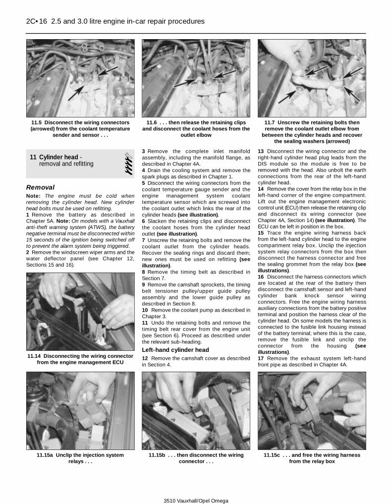
11 Cylinder head - removal and refitting 4
RemovalNote: The engine must be cold whenremoving the cylinder head. New cylinderhead bolts must be used on refitting.1 Remove the battery as described inChapter 5A. Note: On models with a Vauxhallanti-theft warning system (ATWS), the batterynegative terminal must be disconnected within15 seconds of the ignition being switched offto prevent the alarm system being triggered.2 Remove the windscreen wiper arms and thewater deflector panel (see Chapter 12,Sections 15 and 16).
3 Remove the complete inlet manifoldassembly, including the manifold flange, asdescribed in Chapter 4A.4 Drain the cooling system and remove thespark plugs as described in Chapter 1.5 Disconnect the wiring connectors from thecoolant temperature gauge sender and theengine management system coolanttemperature sensor which are screwed intothe coolant outlet which links the rear of thecylinder heads (see illustration).6 Slacken the retaining clips and disconnectthe coolant hoses from the cylinder headoutlet (see illustration).7 Unscrew the retaining bolts and remove thecoolant outlet from the cylinder heads.Recover the sealing rings and discard them;new ones must be used on refitting (seeillustration).8 Remove the timing belt as described inSection 7.9 Remove the camshaft sprockets, the timingbelt tensioner pulley/upper guide pulleyassembly and the lower guide pulley asdescribed in Section 8.10 Remove the coolant pump as described inChapter 3.11 Undo the retaining bolts and remove thetiming belt rear cover from the engine unit(see Section 6). Proceed as described underthe relevant sub-heading.
Left-hand cylinder head12 Remove the camshaft cover as describedin Section 4.
13 Disconnect the wiring connector and theright-hand cylinder head plug leads from theDIS module so the module is free to beremoved with the head. Also unbolt the earthconnections from the rear of the left-handcylinder head.14 Remove the cover from the relay box in theleft-hand corner of the engine compartment.Lift out the engine management electroniccontrol unit (ECU) then release the retaining clipand disconnect its wiring connector (seeChapter 4A, Section 14) (see illustration). TheECU can be left in position in the box.15 Trace the engine wiring harness backfrom the left-hand cylinder head to the enginecompartment relay box. Unclip the injectionsystem relay connectors from the box thendisconnect the harness connector and freethe sealing grommet from the relay box (seeillustrations).16 Disconnect the harness connectors whichare located at the rear of the battery thendisconnect the camshaft sensor and left-handcylinder bank knock sensor wiringconnectors. Free the engine wiring harnessauxiliary connections from the battery positiveterminal and position the harness clear of thecylinder head. On some models the harness isconnected to the fusible link housing insteadof the battery terminal; where this is the case,remove the fusible link and unclip theconnector from the housing (seeillustrations).17 Remove the exhaust system left-handfront pipe as described in Chapter 4A.
2C•16 2.5 and 3.0 litre engine in-car repair procedures
11.5 Disconnect the wiring connectors(arrowed) from the coolant temperature
sender and sensor . . .
11.6 . . . then release the retaining clipsand disconnect the coolant hoses from the
outlet elbow
11.7 Unscrew the retaining bolts thenremove the coolant outlet elbow from
between the cylinder heads and recoverthe sealing washers (arrowed)
11.15a Unclip the injection system relays . . .
11.14 Disconnecting the wiring connectorfrom the engine management ECU
11.15b . . . then disconnect the wiringconnector . . .
11.15c . . . and free the wiring harnessfrom the relay box
3510 Vauxhall/Opel Omega

18 Remove the power steering pump asdescribed in Chapter 10.19 Slacken the retaining clip and disconnectthe radiator upper coolant hose from the pipeat the front of the left-hand cylinder head.20 Unscrew the bolt and spacer securing thecoolant pipe and engine lifting bracket to thecylinder head and remove the lifting bracket.Move the coolant pipe to the left to free it fromthe thermostat housing then manoeuvre it outof position (see illustrations). Remove thesealing rings from the inner end of the pipeand discard them; new ones must be used onrefitting.21 Remove the dipstick then free the dipsticktube from the cylinder block and remove itfrom the engine. Discard the tube sealingrings; new ones should be used on refitting.22 Remove the exhaust camshaft asdescribed in Section 10.
23 Working in the reverse of the tighteningsequence (see illustration 11.41a),progressively slacken the cylinder head boltsby a quarter of a turn at a time until all boltscan be unscrewed by hand (see illustration).Remove each bolt in turn, along with itswasher.24 Lift the cylinder head from the cylinderblock (see illustration). If necessary, tap thecylinder head gently with a soft-faced malletto free it from the block, but do not lever atthe mating faces. Note the fitted positions ofthe two locating dowels, and remove them forsafe keeping if they are loose.25 Recover the cylinder head gasket, anddiscard it.
Right-hand cylinder head26 Position a suitable container beneath theoil filter. Unscrew the filter using an oil filter
removal tool if necessary, and drain the oilinto the container. If the oil filter is damaged ordistorted during removal, it must be renewed.Given the low cost of a new oil filter relative tothe cost of repairing the damage which couldresult if a re-used filter springs a leak, it isprobably a good idea to renew the filter in anycase.27 Unscrew the union nuts securing the oilcooler pipes to the cylinder block thenunscrew the union bolts securing the pipes tothe cooler. Recover the sealing washers fromeach side of the oil cooler unions and movethe pipes to the rear (see illustrations).28 Release the retaining clips and disconnectthe radiator bottom hose, expansion tankhose and heater hose from the coolant pipewhich runs along the right-hand side of theengine. Slacken and remove the retainingbolts then remove the pipe from the engine.
2.5 and 3.0 litre engine in-car repair procedures 2C•17
2C
11.16a Disconnect the harnessconnectors located at the rear of the
battery
11.16b Where the engine harness isconnected to the fusible link housing,
remove the fusible link . . .
11.16d Once all the wiring has beendisconnected, position the harness clear
of the cylinder head
11.16c . . . then unclip the connector fromthe housing
11.23 Evenly and progressively slackenand remove the cylinder head bolts . . .
11.20a Slacken and remove the retainingbolt and spacer . . .
11.20b . . . then remove the coolant pipefrom the thermostat housing (shown with
engine removed)
11.24 . . . then lift the cylinder head off the block
11.27a Unscrew the union nuts (arrowed)securing the oil pipes to the cylinder
block . . .
3510 Vauxhall/Opel Omega
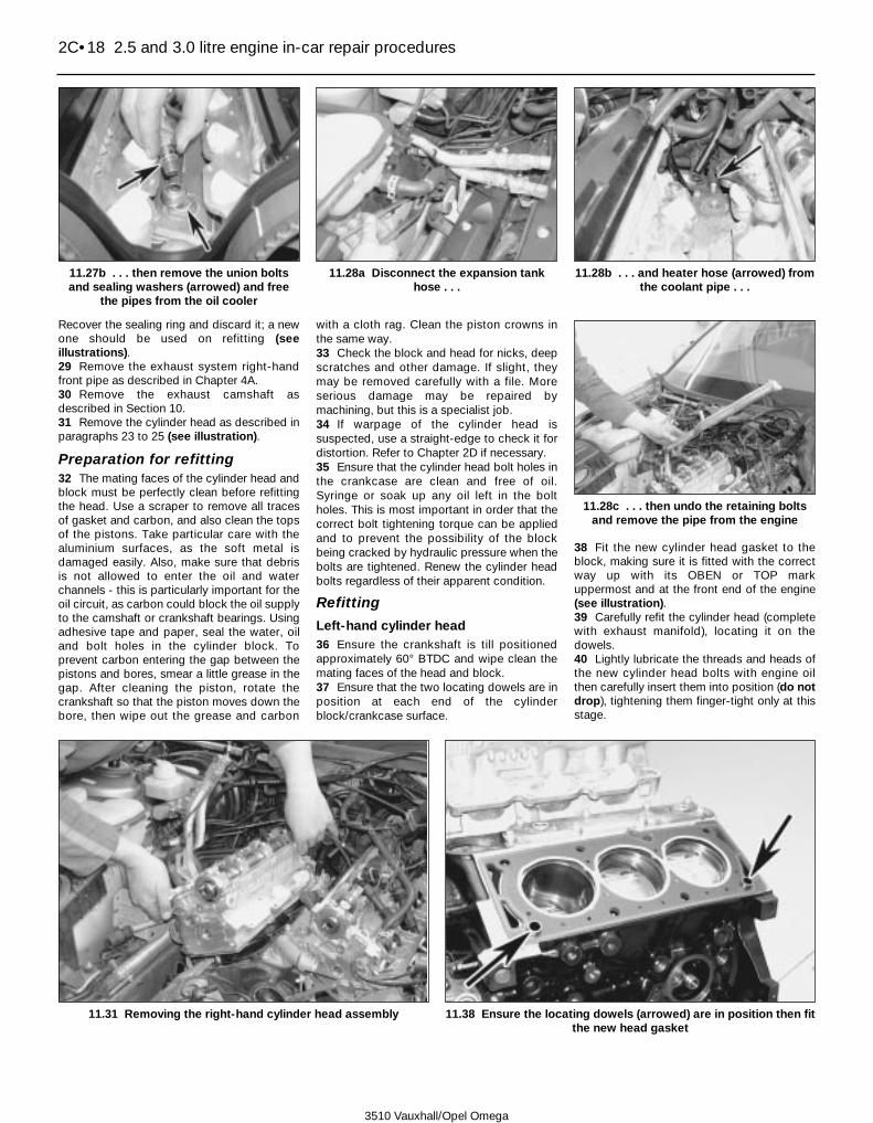
Recover the sealing ring and discard it; a newone should be used on refitting (seeillustrations).29 Remove the exhaust system right-handfront pipe as described in Chapter 4A.30 Remove the exhaust camshaft asdescribed in Section 10.31 Remove the cylinder head as described inparagraphs 23 to 25 (see illustration).
Preparation for refitting32 The mating faces of the cylinder head andblock must be perfectly clean before refittingthe head. Use a scraper to remove all tracesof gasket and carbon, and also clean the topsof the pistons. Take particular care with thealuminium surfaces, as the soft metal isdamaged easily. Also, make sure that debrisis not allowed to enter the oil and waterchannels - this is particularly important for theoil circuit, as carbon could block the oil supplyto the camshaft or crankshaft bearings. Usingadhesive tape and paper, seal the water, oiland bolt holes in the cylinder block. Toprevent carbon entering the gap between thepistons and bores, smear a little grease in thegap. After cleaning the piston, rotate thecrankshaft so that the piston moves down thebore, then wipe out the grease and carbon
with a cloth rag. Clean the piston crowns inthe same way.33 Check the block and head for nicks, deepscratches and other damage. If slight, theymay be removed carefully with a file. Moreserious damage may be repaired bymachining, but this is a specialist job.34 If warpage of the cylinder head issuspected, use a straight-edge to check it fordistortion. Refer to Chapter 2D if necessary.35 Ensure that the cylinder head bolt holes inthe crankcase are clean and free of oil.Syringe or soak up any oil left in the boltholes. This is most important in order that thecorrect bolt tightening torque can be appliedand to prevent the possibility of the blockbeing cracked by hydraulic pressure when thebolts are tightened. Renew the cylinder headbolts regardless of their apparent condition.
Refitting
Left-hand cylinder head36 Ensure the crankshaft is till positionedapproximately 60° BTDC and wipe clean themating faces of the head and block.37 Ensure that the two locating dowels are inposition at each end of the cylinderblock/crankcase surface.
38 Fit the new cylinder head gasket to theblock, making sure it is fitted with the correctway up with its OBEN or TOP markuppermost and at the front end of the engine(see illustration).39 Carefully refit the cylinder head (completewith exhaust manifold), locating it on thedowels.40 Lightly lubricate the threads and heads ofthe new cylinder head bolts with engine oilthen carefully insert them into position (do notdrop), tightening them finger-tight only at thisstage.
2C•18 2.5 and 3.0 litre engine in-car repair procedures
11.27b . . . then remove the union boltsand sealing washers (arrowed) and free
the pipes from the oil cooler
11.28a Disconnect the expansion tankhose . . .
11.28b . . . and heater hose (arrowed) fromthe coolant pipe . . .
11.38 Ensure the locating dowels (arrowed) are in position then fitthe new head gasket
11.28c . . . then undo the retaining boltsand remove the pipe from the engine
11.31 Removing the right-hand cylinder head assembly
3510 Vauxhall/Opel Omega

41 Working progressively and in thesequence shown, first tighten all the cylinderhead bolts to the stage 1 torque setting (seeillustrations).42 Once all bolts have been tightened to thestage 1 torque, again working in the sequenceshown, tighten each bolt through its specifiedstage 2 angle, using a socket and extensionbar. It is recommended that an angle-measuring gauge is used during this stage ofthe tightening, to ensure accuracy (seeillustration).43 Working in the specified sequence, goaround again and tighten all bolts through thespecified stage 3 angle.44 Working again in the specified sequence,go around and tighten all bolts through thespecified stage 4 angle.45 Finally go around in the specifiedsequence again and tighten all bolts throughthe specified stage 5 angle.46 The remainder of the refitting procedure isthe reverse of removal noting the followingpointsa) If the right-hand cylinder head has also
been removed, refit this to the blockbefore connecting any ancillaries.
b) Fit new sealing rings to the dipstick tubeand thermostat housing coolant pipe.Ensure the coolant pipe, dipstick tube andlifting bracket are correctly positionedbefore refitting the retaining bolt andspacer and tightening to the specifiedtorque.
c) Ensure the engine wiring harness iscorrectly routed and securely reconnectall the wiring connectors. Also make surethe earth lead retaining bolts are securelytightened.
d) Refit the camshaft, timing belt andassociated components as described inSections 6 to 10.
e) Use new sealing rings when refitting thecoolant outlet to the cylinder heads and
tighten the retaining bolts to the specifiedtorque.
f) Ensure all coolant hoses are correctlyreconnected and securely retained bytheir clips.
g) Refit the exhaust front pipe and inletmanifold as described in Chapter 4A.
h) On completion refill the cooling systemand power steering fluid reservoir (seeChapter 1 and Weekly checks).
Right-hand cylinder head47 Refit the cylinder head as described inparagraphs 36 to 45 noting that the cylinderhead gasket OBEN or TOP mark must beuppermost and at the rear end of the engine.48 The remainder of the refitting procedure isthe reverse of removal noting the followingpointsa) If the left-hand cylinder head has also
been removed, refit this to the blockbefore connecting any ancillaries.
b) Fit a new sealing ring to coolant pipe andsecurely tighten the pipe retaining bolts.
c) Fit new sealing washers to each side ofthe oil cooler pipe unions and tighten thepipe union nuts and bolts to the specifiedtorque.
d) Refit the camshaft, timing belt andassociated components as described inSections 6 to 10.
e) Use new sealing rings when refitting thecoolant outlet to the cylinder heads andtighten the retaining bolts to the specifiedtorque.
f) Ensure all coolant hoses are correctlyreconnected and securely retained bytheir clips.
g) Refit the exhaust front pipe and inletmanifold as described in Chapter 4A.
h) Fit a new oil filter and refill the coolingsystem as described in Chapter 1.
i) On completion, check the engine oil levelas described in Weekly checks.
12 Sump - removal and refitting 4
Removal
Sump panNote: New sump pan retaining bolts will berequired on refitting.1 Disconnect the battery negative terminal.Note: On models with a Vauxhall anti-theftwarning system (ATWS), the battery negativeterminal must be disconnected within 15seconds of the ignition being switched off toprevent the alarm system being triggered.2 Firmly apply the handbrake then jack up thefront of the car and support it on axle stands.Undo the retaining screws and remove theundercover from beneath the engine.3 Drain the engine oil as described in Chap-ter 1, then fit a new sealing washer and refitthe drain plug, tightening it to the specifiedtorque.4 Disconnect the wiring connector from theoil level sensor connector on the right-hand
2.5 and 3.0 litre engine in-car repair procedures 2C•19
2C
11.42 . . . and then through the specifiedstage 2 to 5 angles using an angle
measuring gauge for accuracy
3510 Vauxhall/Opel Omega
11.41a Cylinder head bolt tightening sequence (left-hand head shown)
11.41b Working in the specified sequence, tighten the cylinderhead bolts to the specified stage 1 torque . . .

side of the main casting then slide off theretaining clip and push the connector into thesump (see illustration).5 Slacken and remove the sump panretaining bolts then free it from the maincasting and remove it along with its gasket.Take care not to damage the oil level sensorwiring as the pan is removed.6 If necessary, undo the retaining bolts (oneis tricky to reach) and remove the oil pumppick-up/strainer from the base of the oil pumphousing along with its sealing ring. Check theoil pump pick-up/strainer for signs of cloggingor splitting and renew/clean as necessary.
Main castingNote: New front suspension subframemounting bolts will be required on refitting.New retaining nuts for the centre tie rod willalso be required.7 Remove the sump pan and oil pick-up/strainer as described in paragraphs 1 to 6.8 Referring to Chapter 12, on models withXenon headlights, disconnect the wiringconnector from the headlight system frontvehicle level control sensor then unclip thelink rod from the sensor arm balljoint.9 Remove the steering linkage centre tie rodas described in Chapter 10, Section 25.10 Slacken and remove the mounting boltsand remove the vibration dampers from theleft- and right-hand engine mountings11 Slacken and remove the nuts securing theengine left- and right-hand mountings to thesubframe.
12 Attach an engine hoist to the engine liftingbrackets then raise the hoist until it issupporting the weight of the engine.Alternatively use an engine support bar totake the weight of the engine.13 Referring to Chapter 10, unscrew the frontsuspension subframe front mounting bolts byapproximately 4 turns. Support the rear of thesubframe with a jack then slacken and removethe rear mounting bolts. Lower the rear of thesubframe approximately 10 cm to gain accessto the main casting.14 Unscrew the bolts securing the maincasting flange to the transmission housingthen progressively slacken and remove thebolts securing the main casting to the base ofthe cylinder block/oil pump. Break the joint bystriking the casting with the palm of the hand,then lower it away from the engine andwithdraw it. Remove the seal and discard it.Note: If the main casting is to be removed forany length of time, raise the subframe back upinto position and refit its mounting bolts thenlower the engine back down onto thesubframe.
Refitting
Sump pan15 Remove all traces of dirt and oil from themating surfaces of the sump pan, maincasting and (if necessary) the pick-up/strainerand oil pump housing.16 Where necessary, position a new sealingring on top of the oil pump pick-up/strainer
then refit the strainer, tightening its retainingbolts to the specified torque (see illustration).17 Ensure the sump pan and main castingsurfaces are clean and dry and fit a newsealing ring to the oil level sensor wiringconnector.18 Place a new gasket on the top of the panand offer it up to the main casting. Seat the oillevel sensor wiring connector in the maincasting, securing it in position with theretaining clip, then seat the sump pan on themain casting (see illustration).19 Fit the new sump pan retaining bolts thengo around in a diagonal sequence and tightenthem to the specified stage 1 torque setting.Once all bolts have been tightened go aroundagain and angle-tighten them through thespecified stage 2 angle. It is recommendedthat an angle-measuring gauge is used duringthis stage of the tightening, to ensureaccuracy.20 Reconnect the oil level sender wiringconnector then refit the undercover.21 Lower the vehicle to the ground then fillthe engine with fresh oil, with reference toChapter 1.
Main casting22 Remove all traces of dirt and oil from themating surfaces of the main casting andcylinder block.23 Ensure the main casting seal groove iscompletely dry then apply a bead of sealant(Vauxhall recommend the use of sealant 15 03298 - available from your Vauxhall dealer) tothe areas of the groove shown (seeillustration). Note: If the Vauxhall sealant isbeing used, the main casting must be boltedin position on the cylinder block within tenminutes of applying the sealant.24 Locate the new seal correctly in its groovethen apply a bead of the sealant,approximately 3mm in diameter, to the maincasting surface as shown (see illustrations).The sealant should go around the outside ofthe seal around the front of the casting andthe inside at the rear, making sure the sealantoverlaps at the points shown.25 Apply a smear of suitable sealant (Vauxhallrecommend the use of sealant 15 03 295 -available from your Vauxhall dealer) to theareas of the cylinder block mating surface
2C•20 2.5 and 3.0 litre engine in-car repair procedures
12.4 Slide off the retaining clip and pushthe oil level sensor wiring connector into
the sump
12.16 Fit a new sealing ring to the oilpump pick-up/strainer before refitting
12.18 On refitting, locate the oil levelsensor wiring connector in the main casting
before bolting the sump pan in position
12.23 Apply a bead of sealant (arrowed) tothe main casting seal groove in between
the lines shown . . .
12.24a . . . then locate the new seal in thecasting groove
3510 Vauxhall/Opel Omega
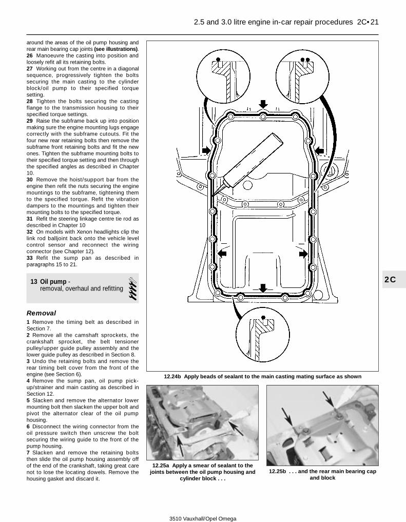
around the areas of the oil pump housing andrear main bearing cap joints (see illustrations).26 Manoeuvre the casting into position andloosely refit all its retaining bolts.27 Working out from the centre in a diagonalsequence, progressively tighten the boltssecuring the main casting to the cylinderblock/oil pump to their specified torquesetting.28 Tighten the bolts securing the castingflange to the transmission housing to theirspecified torque settings.29 Raise the subframe back up into positionmaking sure the engine mounting lugs engagecorrectly with the subframe cutouts. Fit thefour new rear retaining bolts then remove thesubframe front retaining bolts and fit the newones. Tighten the subframe mounting bolts totheir specified torque setting and then throughthe specified angles as described in Chapter10.30 Remove the hoist/support bar from theengine then refit the nuts securing the enginemountings to the subframe, tightening themto the specified torque. Refit the vibrationdampers to the mountings and tighten theirmounting bolts to the specified torque.31 Refit the steering linkage centre tie rod asdescribed in Chapter 1032 On models with Xenon headlights clip thelink rod balljoint back onto the vehicle levelcontrol sensor and reconnect the wiringconnector (see Chapter 12).33 Refit the sump pan as described inparagraphs 15 to 21.
13 Oil pump - removal, overhaul and refitting 4
Removal1 Remove the timing belt as described inSection 7.2 Remove all the camshaft sprockets, thecrankshaft sprocket, the belt tensionerpulley/upper guide pulley assembly and thelower guide pulley as described in Section 8.3 Undo the retaining bolts and remove therear timing belt cover from the front of theengine (see Section 6).4 Remove the sump pan, oil pump pick-up/strainer and main casting as described inSection 12.5 Slacken and remove the alternator lowermounting bolt then slacken the upper bolt andpivot the alternator clear of the oil pumphousing.6 Disconnect the wiring connector from theoil pressure switch then unscrew the boltsecuring the wiring guide to the front of thepump housing.7 Slacken and remove the retaining boltsthen slide the oil pump housing assembly offof the end of the crankshaft, taking great carenot to lose the locating dowels. Remove thehousing gasket and discard it.
2.5 and 3.0 litre engine in-car repair procedures 2C•21
2C
12.25a Apply a smear of sealant to thejoints between the oil pump housing and
cylinder block . . .12.25b . . . and the rear main bearing cap
and block
3510 Vauxhall/Opel Omega
12.24b Apply beads of sealant to the main casting mating surface as shown

Overhaul8 Undo the retaining screws and lift off thepump cover from the rear of the housing (seeillustration).
9 Using a suitable marker pen, mark thesurface of both the pump inner and outerrotors; the marks can then be used to ensurethe rotors are refitted the correct way around.On some pump identification marks mayalready exist on the rotors (see illustration).10 Lift out the inner and outer rotors from thepump housing (see illustration).11 Unscrew the oil pressure relief valve andthe safety valve bolts from the top of thehousing and withdraw the valve springs andplungers from the housing, noting which wayaround the plungers are fitted. Remove thesealing washers from the valve bolts (seeillustrations). Note: The pressure relief valvecan be removed with pump in position on theengine unit once the timing belt front coverhas been removed.12 Clean the components, and carefullyexamine the rotors, pump body and valve
plungers for any signs of scoring or wear.Renew any component which shows signs ofwear or damage; if the rotors or pumphousing are marked then the complete pumpassembly should be renewed.13 If the components appear serviceable,measure the rotor endfloat, and check theflatness of the end cover. If the clearancesexceed the specified tolerances, the pumpmust be renewed.14 If the pump is satisfactory, reassemble thecomponents in the reverse order of removal,noting the following.a) Ensure both rotors are fitted the correct
way around.b) Tighten the pump cover screws to the
specified torque.c) Fit new sealing rings to the valve bolts and
ensure the plungers and springs are fittedthe correct way around (see illustrations).
2C•22 2.5 and 3.0 litre engine in-car repair procedures
13.8 Undo the retaining screws andremove the cover from the oil pump
13.9 Note the identification markings(where present) on the pump rotors . . .
13.10 . . . then lift both rotors out of thehousing
13.11a Slacken and remove the oilpressure relief valve bolt and sealing
washer . . .13.11b . . . then remove the valve plunger
and spring from the pump13.11c Slacken and remove the safety
valve bolt and sealing washer . . .
13.11d . . . and withdraw the spring andplunger from the pump
3510 Vauxhall/Opel Omega
13.14a Oil pressure relief valve components
1 Spring2 Plunger
3 Sealing washer4 Valve bolt
13.14b Safety valve components
1 Plunger2 Spring
3 Sealing washer4 Valve bolt

d) On completion prime the oil pump byfilling it with clean engine oil whilstrotating the inner rotor.
Refitting15 Prior to refitting it is necessary to determinewhich of the three possible types of oil pumpassembly is fitted to your engine. The first stepis to check the diameter of the oil pumpretaining bolts; during the 1999 model year thepump retaining bolt diameter was increasedfrom M6 to M8. If M6 retaining bolts are used, itwill then be necessary to determine whetherthe engine is fitted with an original oil pumpand timing belt rear cover arrangement or themodified arrangement (see illustration). Themodified cover has an additional hole throughwhich the oil pump upper bolt (number 6 in thetightening sequence) can be reached and thisaffects the refitting procedure. Proceed asdescribed under the relevant sub-heading.
Oil pump with M6 retaining bolts andthe original timing belt rear cover16 Prior to refitting, carefully lever out thecrankshaft oil seal using a flat-bladedscrewdriver. Fit the new oil seal, ensuring itssealing lip is facing inwards, and press itsquarely into the housing using a tubular driftwhich bears only on the hard outer edge ofthe seal (see illustrations). Press the seal intoposition so that it is flush with the housing andlubricate the oil seal lip with clean engine oil.17 Ensure the mating surfaces of the oilpump and cylinder block are clean and dryand the locating dowels are in position.18 Apply a thin coat of sealant (Vauxhallrecommend the use of sealant 15 03 170 -available from your Vauxhall dealer),approximately 0.2 mm thick, to the shadedareas of the oil pump side of the new pumpgasket as shown (see illustration).19 Fit the gasket to the cylinder block thencarefully manoeuvre the oil pump into positionand engage the inner rotor with the crankshaftend. Locate the pump on the dowels, takinggreat care not damage the oil seal lip (seeillustrations).20 Refit the pump housing retaining bolts intheir original locations and tighten them to theinitial specified torque in the order shown (seeillustration).
2.5 and 3.0 litre engine in-car repair procedures 2C•23
2C
13.18 Apply sealant (see text) to theshaded areas of the oil pump side of the
new gasket
13.16a Lever out the oil seal out from thepump with a large flat-bladed
screwdriver . . .
13.16b . . . and tap the new seal squarelyinto position, using a socket which bears
only on the seal outer edge
13.19a Locate the pump gasket on thedowels . . .
13.19b . . . then refit the oil pumpassembly
3510 Vauxhall/Opel Omega
13.15 Oil pump and timing belt rear cover identification details (pump retained by M6 bolts)
A Original pump and timing belt coverB Modified pump and timing belt cover (shaded areas show differences) which allow
access to the bolt shown with the cover in position

21 Fit the timing belt lower guide pulley to thepump and tighten its retaining bolt to thespecified torque.22 Refit the alternator lower mounting boltand tighten to the specified torque (seeChapter 5A).23 Wait approximately 10 minutes to allowthe sealant on the pump gasket to cure thengo around again in the specified sequenceand tighten them to the final specified torquesetting.24 Remove the lower guide pulley from theoil pump and refit the timing belt rear cover(see Section 6), tightening its retaining bolts tothe specified torque.25 Reconnect the oil pressure sensor wiringconnector and secure the wiring guide inposition with the bolt.26 Refit the sump main casting, oil pumppick-up/strainer and sump pan as describedin Section 12.27 Refit the timing belt sprockets, guidepulleys and tensioner then refit the belt asdescribed in Sections 7 and 8.28 On completion, fit a new oil filter and fillthe engine with clean oil as described inChapter 1.
Oil pump with M6 retaining bolts andthe modified timing belt rear cover29 Carry out the operations described inparagraphs 16 to 19.30 Refit the pump housing retaining bolts intheir original locations and tighten them to thespecified torque in the order shown (seeillustration 13.20).31 Refit the alternator lower mounting boltand tighten to the specified torque (seeChapter 5A).32 Refit the timing belt rear cover (seeSection 6) and tighten its retaining bolts to thespecified torque.33 Reconnect the oil pressure sensor wiringconnector and secure the wiring guide in
position with the retaining bolt.34 Refit the sump main casting, oil pumppick-up/strainer and sump pan as describedin Section 12.35 Refit the timing belt sprockets, guidepulleys and tensioner then refit the belt asdescribed in Sections 7 and 8. Prior torefitting the timing belt outer cover, go aroundin the specified sequence (see illustration13.20) and retighten all the oil pump retainingbolts to the specified torque.36 On completion, fit a new oil filter and fillthe engine with clean oil as described inChapter 1.
Oil pump with M8 retaining bolts37 Remove all traces of locking compoundfrom the oil pump retaining bolt threads.38 Carry out the operations described inparagraphs 16 to 19.39 Apply a drop of locking compound(Vauxhall recommend the use of lockingcompound 15 10 181 - available from yourVauxhall dealer) to the thread of each pumpretaining bolt then refit the bolts in theiroriginal locations, tightening them by handonly.
40 Go around in the specified sequence andtighten all the pump retaining bolts to thespecified stage 1 torque setting (seeillustration).41 Refit the alternator lower mounting boltand tighten to the specified torque (seeChapter 5A).42 Go around again in the specifiedsequence and tighten all the pump retainingbolts to the specified stage 2 torque setting.43 Reconnect the oil pressure sensor wiringconnector and secure the wiring guide inposition with the retaining bolt.44 Refit the timing belt rear cover (seeSection 6) and tighten its retaining bolts to thespecified torque.45 Refit the sump main casting, oil pumppick-up/strainer and sump pan as describedin Section 12.46 Refit the timing belt sprockets, guidepulleys and tensioner then refit the belt asdescribed in Sections 7 and 8.47 On completion, fit a new oil filter and fillthe engine with clean oil as described inChapter 1.
14 Oil cooler - removal and refitting 4
Removal1 Drain the cooling system as described inChapter 1.2 Remove the complete inlet manifold,including the manifold flange, as described inChapter 4A.3 Disconnect the wiring connectors from thecoolant temperature gauge sender and theengine management system coolanttemperature sensor which are screwed intothe coolant outlet which links the rear of thecylinder heads (see illustration).
2C•24 2.5 and 3.0 litre engine in-car repair procedures
14.3 Disconnect the wiring connectors(arrowed) from the coolant temperature
sender and sensor . . .
3510 Vauxhall/Opel Omega
13.20 Oil pump bolt tightening sequence - pump with M6 retaining bolts
13.40 Oil pump bolt tightening sequence - pump with M8 retaining bolts

4 Slacken the retaining clips and disconnectthe coolant hoses from the cylinder headoutlet (see illustration).5 Unscrew the retaining bolts and remove thecoolant outlet from the cylinder heads.Recover the sealing rings and discard them;new ones must be used on refitting (seeillustration).6 Undo the retaining bolts and remove theupper heatshield from the left-hand cylinderbank exhaust manifold. If necessary, toimprove access to the rear bolt remove the
exhaust system front pipe as described inChapter 4A.7 Position a suitable container beneath the oilfilter. Unscrew the filter using an oil filterremoval tool if necessary, and drain the oilinto the container. If the oil filter is damaged ordistorted during removal, it must be renewed.Given the low cost of a new oil filter relative tothe cost of repairing the damage which couldresult if a re-used filter springs a leak, it isprobably a good idea to renew the filter in anycase.
8 Unscrew the union nuts securing the oilcooler pipes to the cylinder block then unscrewthe union bolts securing the pipes to thecooler. Recover the sealing washers from eachside of the oil cooler unions and position thepipes clear of the oil cooler (see illustrations).9 Unscrew the large nuts securing the oilcooler unions to the cover then undo theretaining bolts and remove the cover from thetop of the cylinder block (see illustrations).Recover the gasket (where fitted) and discardit; sealant will be needed to replace the gasketon refitting.10 Lift out the oil cooler and remove it fromthe engine, keeping it upright to prevent oilspillage (see illustration). Recover the sealingrings from the cooler unions and discardthem; new ones must be used on refitting.11 If the oil cooler shows signs of damage itmust be renewed.
Refitting12 Ensure the mating surfaces of the oilcooler, cover and cylinder block are clean anddry.13 Fit new sealing rings to the oil coolerunions then refit the cover and screw on thelarge nuts, tightening them by hand only atthis stage.
2.5 and 3.0 litre engine in-car repair procedures 2C•25
2C
14.9a Unscrew the large nuts from thecooler unions . . .
14.9b . . . then undo the retaining boltsand lift off the oil cooler cover
14.8a Slacken the union nuts (arrowed)securing the oil pipes to the block . . .
14.8b . . . then remove the union bolts andsealing washers (arrowed) and free the
pipes from the oil cooler
14.10 Removing the oil cooler from thecylinder block
3510 Vauxhall/Opel Omega
14.4 . . . then release the retaining clips and disconnect thecoolant hoses from the outlet elbow
14.5 Unscrew the retaining bolts then remove the coolant outletelbow from between the cylinder heads and recover the sealing
washers (arrowed)

14 Apply a bead of suitable sealant (Vauxhallrecommend the use of sealant 15 03 296 -available from your Vauxhall dealer), approx-imately 2 mm in diameter, to the groove on theoil cooler cover (see illustration).15 Refit the cooler assembly to the cylinderblock and refit the cover retaining bolts,tightening them evenly and progressively totheir specified torque. Once the cover boltsare correctly tightened, tighten the cooler nutsto their specified torque (see illustration).16 Manoeuvre the oil cooler pipes intoposition and screw their union nuts into thecylinder block by a few turns each. Position anew sealing washer on each side of the pipeunions then refit the union bolts. Tighten theunion bolts to the specified torque thentighten the pipe union nuts to the specifiedtorque.17 Fit new sealing rings to each side of thecoolant outlet then refit it to the cylinderheads, tightening its retaining bolts to thespecified torque. Reconnect the hoses to theoutlet, securing them in position with theretaining clips, and the temperature sensorwiring connectors.18 Refit the inlet manifold as described inChapter 4A and install the exhaust manifoldheatshield and (where necessary) front pipe.
19 Fit a new oil filter and refill the coolingsystem as described in Chapter 1.20 On completion, check the engine oil levelas described in Weekly checks.
15 Flywheel/driveplate -removal, inspection andrefitting 4
Note: New flywheel/driveplate retaining boltswill be required on refitting.
Removal
Manual transmission models1 Remove the transmission as described inChapter 7A then remove the clutch assemblyas described in Chapter 6.2 Prevent the flywheel from turning by lockingthe ring gear teeth with a similar arrangementto that shown (see illustration). Alternatively,bolt a strap between the flywheel and thecylinder block/crankcase. Make alignmentmarks between the flywheel and crankshaftusing paint or a suitable marker pen.3 Slacken and remove the retaining bolts andremove the flywheel. Do not drop it, as it isvery heavy.
Automatic transmission models4 Remove the transmission as described inChapter 7B.5 Lock the driveplate as described inparagraph 2 then slacken the driveplateretaining bolts.6 Unscrew the retaining bolts and remove theretaining plate, centering ring and driveplatefrom the end of the crankshaft, noting eachcomponents correct fitted location.
Inspection7 On manual transmission models, examinethe flywheel for scoring of the clutch face. Ifthe clutch face is scored, the flywheel may besurface-ground, but renewal is preferable.
Check for wear or chipping of the ring gearteeth, if the teeth are damaged the flywheelmust be renewed (ring gear renewal is notpossible).8 On automatic transmission models closelyexamine the driveplate for ring gear teeth forsigns of wear or damage and check thedriveplate surface for any signs of cracks.9 If there is any doubt about the condition ofthe flywheel/driveplate, seek the advice of aVauxhall dealer or engine reconditioningspecialist. They will be able to advise if it ispossible to recondition it or whether renewalis necessary.
Refitting
Manual transmission models10 Clean the mating surfaces of the flywheeland crankshaft and remove all traces oflocking compound from the flywheel retainingbolt threads in the crankshaft.11 Offer up the flywheel and fit the newretaining bolts. If the original is being refittedalign the marks made prior to removal.12 Lock the flywheel by the method used onremoval, and tighten the retaining bolts to thespecified stage 1 torque setting then angle-tighten the bolts through the specified stage 2angle, using a socket and extension bar, andfinally through the specified stage 3 angle. It isrecommended that an angle-measuringgauge is used during the final stages of thetightening, to ensure accuracy. If a gauge isnot available, use white paint to makealignment marks between the bolt head andflywheel prior to tightening; the marks canthen be used to check that the bolt has beenrotated through the correct angle.13 Refit the clutch as described in Chapter 6then remove the locking tool, and refit thetransmission as described in Chapter 7A.
Automatic transmission models14 Clean the mating surfaces of thedriveplate and crankshaft and remove all
2C•26 2.5 and 3.0 litre engine in-car repair procedures
15.2 Lock the flywheel/driveplate ring gearwith a tool similar to that shown
3510 Vauxhall/Opel Omega
14.14 Apply a bead of sealant to the groove in the oil cooler cover 14.15 Tighten the cover retaining bolts to the specified torquethen tighten the cooler nuts to their specified torque

traces of locking compound from thedriveplate retaining bolt threads in thecrankshaft.15 Offer up the driveplate complete with thecentering ring and retaining plate, makingsure all components are fitted the correct wayaround, then screw in the new retaining bolts.16 Tighten the retaining bolts through thespecified torque and angles as described inparagraph 12 then remove the locking tooland refit the transmission as described inChapter 7B.
16 Crankshaft oil seals - renewal 4
Front (timing belt end) oil seal1 Remove the crankshaft sprocket andspacer as described in Section 8.2 Carefully punch or drill two small holesopposite each other in the oil seal. Screw aself-tapping screw into each and pull on thescrews with pliers to extract the seal.Alternatively carefully lever the seal out ofposition.Caution: Great care must be taken to avoiddamage to the oil pump3 Clean the seal housing and polish off anyburrs or raised edges which may have causedthe seal to fail in the first place.4 Lubricate the lips of the new seal with cleanengine oil and ease it into position on the endof the shaft. Press the seal squarely intoposition until it is flush with the housing. Ifnecessary, a suitable tubular drift, such as asocket, which bears only on the hard outeredge of the seal can be used to tap the sealinto position. Take great care not to damagethe seal lips during fitting and ensure that theseal lips face inwards.5 Wash off any traces of oil, then refit thespacer and crankshaft sprocket as describedin Section 8.
Rear (flywheel/driveplate end)oil seal6 Remove the flywheel/driveplate asdescribed in Section 15.7 Renew the seal as described in paragraphs 2to 4 (see illustration).8 Refit the flywheel/driveplate as described inSection 15.
17 Engine/transmissionmountings - inspection and renewal
3Inspection1 If improved access is required, raise thefront of the car and support it securely on axlestands. Undo the retaining bolts and removethe undercover from beneath the engine unit.2 Check the mounting rubber to see if it iscracked, hardened or separated from themetal at any point; renew the mounting if anysuch damage or deterioration is evident.3 Check that all the mounting’s fasteners aresecurely tightened; use a torque wrench tocheck if possible.4 Using a large screwdriver or a pry bar,check for wear in the mounting by carefully
levering against it to check for free play;where this is not possible, enlist the aid of anassistant to move the engine/transmissionunit back and forth, or from side to side, whileyou watch the mounting. While some free playis to be expected even from newcomponents, excessive wear should beobvious. If excessive free play is found, checkfirst that the fasteners are correctly secured,then renew any worn components asdescribed below.
Renewal
Left- and right-hand enginemountingsNote: It is recommended that the enginemountings are replaced as a matched pair.5 Firmly apply the handbrake then jack up thefront of the vehicle and support it on axlestands. If necessary, to improve access undothe retaining screws and remove theundercover from beneath the engine unit.6 Support the weight of theengine/transmission using a trolley jack with ablock of wood placed on its head.Alternatively attach an engine hoist/supportbar to the lifting brackets on the cylinder headand use this to support the engine.7 Slacken and remove the mounting boltsand remove the vibration damper (wherefitted) from the mounting assembly.8 Unscrew the upper and lower nuts securingthe relevant engine mounting to the cylinderblock bracket and subframe then raise theengine unit slightly and manoeuvre themounting out of position (see illustrations). Ifnecessary the mounting bracket can beunbolted and removed from the cylinderblock. Note: Take great care not to place anyexcess stress on any engine wiring/hoses orthe exhaust system or when raising theengine.9 Check all components for signs of wear ordamage, and renew as necessary.
2.5 and 3.0 litre engine in-car repair procedures 2C•27
2C
16.7 Fitting a new crankshaft rear oil seal
3510 Vauxhall/Opel Omega
17.8a Slacken and remove the upper and lower nuts . . . 17.8b . . . then lift the engine slightly until there is sufficientclearance to manoeuvre the mounting out of position

10 On refitting, refit the mounting to thesubframe aligning its locating lug with thesubframe slot then refit the lower nut andtighten to the specified torque.11 Refit the mounting bracket (whereremoved) to the cylinder block and tighten itsretaining bolts to the specified torque.12 Lower the engine unit back down onto themounting then refit the upper retaining nut tothe mounting, tightening it to the specifiedtorque.13 Where necessary, refit the vibrationdamper to the mounting bracket andsubframe and tighten its mounting bolts to thespecified torque.14 Refit the undercover (where removed)then lower the vehicle to the ground.
Transmission unit rear mounting15 Firmly apply the handbrake then jack upthe front of the vehicle and support it on axlestands.16 Place a jack with a block of wood beneaththe transmission, and raise the jack to takethe weight of the transmission.17 With the transmission securely supported,slacken and remove the bolts securing thetransmission unit rear mounting crossmemberto the vehicle body. Unscrew the nutssecuring the crossmember to the mountingand remove it from the vehicle.18 Slacken and remove the bolts and removethe mounting from the base of thetransmission unit.19 Check all components for signs of wear or
damage, and renew as necessary. Remove alltraces of locking compound from thecrossmember to body bolt threads.20 Fit the mounting to the transmission unitand tighten its retaining bolts to the specifiedtorque.21 Refit the crossmember to the mountingand lightly tighten its retaining nuts.22 Apply a few drops of thread lockingcompound (Vauxhall recommend the use oflocking compound 15 10 181 - available fromyour Vauxhall dealer) to the threads of eachcrossmember to body bolt then refit bothbolts and tighten them to the specified torque.23 Remove the jack from underneath thetransmission unit then tighten the mounting tocrossmember nuts to the specified torquebefore lowering the vehicle to the ground.
2C•28 2.5 and 3.0 litre engine in-car repair procedures
3510 Vauxhall/Opel Omega

3510 Vauxhall/Opel Omega
2D•1
2D
Chapter 2 Part D:General engine overhaul procedures
Cylinder head2.0 litre engineMaximum gasket face distortion . . . . . . . . . . . . . . . . . . . . . . . . . . . . . . 0.05 mmCylinder head height:
SOHC engine . . . . . . . . . . . . . . . . . . . . . . . . . . . . . . . . . . . . . . . . . . . 95.75 to 96.25 mmDOHC engine . . . . . . . . . . . . . . . . . . . . . . . . . . . . . . . . . . . . . . . . . . . 134 mm
Valve seat width:SOHC engine:
Inlet . . . . . . . . . . . . . . . . . . . . . . . . . . . . . . . . . . . . . . . . . . . . . . . . . 1.0 to 1.5 mmExhaust . . . . . . . . . . . . . . . . . . . . . . . . . . . . . . . . . . . . . . . . . . . . . . 1.7 to 2.2 mm
DOHC engine:Inlet . . . . . . . . . . . . . . . . . . . . . . . . . . . . . . . . . . . . . . . . . . . . . . . . . 1.0 to 1.4 mmExhaust . . . . . . . . . . . . . . . . . . . . . . . . . . . . . . . . . . . . . . . . . . . . . . 1.4 to 1.8 mm
Valve guide height in cylinder head:SOHC engine . . . . . . . . . . . . . . . . . . . . . . . . . . . . . . . . . . . . . . . . . . . 83.25 to 84.05 mmDOHC engine . . . . . . . . . . . . . . . . . . . . . . . . . . . . . . . . . . . . . . . . . . . 13.70 to 14.00 mm
2.5 and 3.0 litre engineMaximum gasket face distortion . . . . . . . . . . . . . . . . . . . . . . . . . . . . . . 0.05 mmCylinder head height . . . . . . . . . . . . . . . . . . . . . . . . . . . . . . . . . . . . . . . . 134 mmValve seat width:
Inlet . . . . . . . . . . . . . . . . . . . . . . . . . . . . . . . . . . . . . . . . . . . . . . . . . . . 1.0 to 1.4 mmExhaust . . . . . . . . . . . . . . . . . . . . . . . . . . . . . . . . . . . . . . . . . . . . . . . . 1.4 to 1.8 mm
Valve guide height in cylinder head . . . . . . . . . . . . . . . . . . . . . . . . . . . . 13.7 to 14.0 mm
Crankshaft - inspection . . . . . . . . . . . . . . . . . . . . . . . . . . . . . . . . . . . 13Crankshaft - refitting and main bearing running clearance check . . . 17Crankshaft - removal . . . . . . . . . . . . . . . . . . . . . . . . . . . . . . . . . . . . . 10Cylinder block - cleaning and inspection . . . . . . . . . . . . . . . . . . . . . 11Cylinder head - dismantling . . . . . . . . . . . . . . . . . . . . . . . . . . . . . . . . 6Cylinder head - reassembly . . . . . . . . . . . . . . . . . . . . . . . . . . . . . . . . 8Cylinder head and valves - cleaning and inspection . . . . . . . . . . . . . 7Engine - initial start up after overhaul . . . . . . . . . . . . . . . . . . . . . . . . 19Engine - removal and refitting . . . . . . . . . . . . . . . . . . . . . . . . . . . . . . 4Engine overhaul - dismantling sequence . . . . . . . . . . . . . . . . . . . . . . 5
Engine overhaul - general information . . . . . . . . . . . . . . . . . . . . . . . . 2Engine overhaul - reassembly sequence . . . . . . . . . . . . . . . . . . . . . . 15Engine removal - methods and precautions . . . . . . . . . . . . . . . . . . . 3General information . . . . . . . . . . . . . . . . . . . . . . . . . . . . . . . . . . . . . . 1Main and big-end bearings - inspection . . . . . . . . . . . . . . . . . . . . . . 14Piston rings - refitting . . . . . . . . . . . . . . . . . . . . . . . . . . . . . . . . . . . . 16Piston/connecting rod assembly - inspection . . . . . . . . . . . . . . . . . . 12Piston/connecting rod assembly - refitting and big-end running
clearance check . . . . . . . . . . . . . . . . . . . . . . . . . . . . . . . . . . . . . . . 18Piston/connecting rod assembly - removal . . . . . . . . . . . . . . . . . . . . 9
Specifications
Contents
Easy, suitable fornovice with littleexperience
Fairly easy, suitablefor beginner withsome experience
Fairly difficult,suitable for competentDIY mechanic
Difficult, suitable forexperienced DIYmechanic
Very difficult,suitable for expert DIYor professional
Degrees of difficulty
54321

Valves and guides2.0 litre engineValve stem diameter*:
SOHC engine:Inlet:
Standard (GM) . . . . . . . . . . . . . . . . . . . . . . . . . . . . . . . . . . . . . . . 6.998 to 7.012 mm1st oversize (0.075 mm - GM K1) . . . . . . . . . . . . . . . . . . . . . . . . 7.073 to 7.087 mm2nd oversize (0.150 mm - GM K2) . . . . . . . . . . . . . . . . . . . . . . . 7.148 to 7.162 mm3rd oversize (0.250 mm - A) . . . . . . . . . . . . . . . . . . . . . . . . . . . . 7.248 to 7.262 mm
Exhaust:Standard (GM) . . . . . . . . . . . . . . . . . . . . . . . . . . . . . . . . . . . . . . . 6.978 to 6.992 mm1st oversize (0.075 mm - GM K1) . . . . . . . . . . . . . . . . . . . . . . . . 7.053 to 7.067 mm2nd oversize (0.150 mm - GM K2) . . . . . . . . . . . . . . . . . . . . . . . 7.128 to 7.142 mm3rd oversize (0.250 mm - A) . . . . . . . . . . . . . . . . . . . . . . . . . . . . 7.228 to 7.262 mm
DOHC engine:Inlet:
Standard (GM) . . . . . . . . . . . . . . . . . . . . . . . . . . . . . . . . . . . . . . . 5.955 to 5.970 mm1st oversize (0.075 mm - GM K1) . . . . . . . . . . . . . . . . . . . . . . . . 6.030 to 6.045 mm2nd oversize (0.150 mm - GM K2) . . . . . . . . . . . . . . . . . . . . . . . 6.105 to 6.120 mm
Exhaust:Standard (GM) . . . . . . . . . . . . . . . . . . . . . . . . . . . . . . . . . . . . . . . 5.945 to 5.960 mm1st oversize (0.075 mm - GM K1) . . . . . . . . . . . . . . . . . . . . . . . . 6.020 to 6.035 mm2nd oversize (0.0150 mm - GM K2) . . . . . . . . . . . . . . . . . . . . . . 6.095 to 6.110 mm
Valve stem runout . . . . . . . . . . . . . . . . . . . . . . . . . . . . . . . . . . . . . . . . . . Less than 0.03 mmValve guide bore diameter:
SOHC engine:Standard . . . . . . . . . . . . . . . . . . . . . . . . . . . . . . . . . . . . . . . . . . . . . 7.030 to 7.050 mm1st oversize (0.075 mm) . . . . . . . . . . . . . . . . . . . . . . . . . . . . . . . . . 7.105 to 7.125 mm2nd oversize (0.150 mm) . . . . . . . . . . . . . . . . . . . . . . . . . . . . . . . . . 7.180 to 7.200 mm3rd oversize (0.250 mm) . . . . . . . . . . . . . . . . . . . . . . . . . . . . . . . . . 7.280 to 7.300 mm
DOHC engine:Standard . . . . . . . . . . . . . . . . . . . . . . . . . . . . . . . . . . . . . . . . . . . . . 6.000 to 6.012 mm1st oversize (0.075 mm) . . . . . . . . . . . . . . . . . . . . . . . . . . . . . . . . . 6.075 to 6.090 mm2nd oversize (0.150 mm) . . . . . . . . . . . . . . . . . . . . . . . . . . . . . . . . . 6.150 to 6.165 mm
Stem-to-guide clearance:SOHC engine:
Inlet . . . . . . . . . . . . . . . . . . . . . . . . . . . . . . . . . . . . . . . . . . . . . . . . . 0.018 to 0.052 mmExhaust . . . . . . . . . . . . . . . . . . . . . . . . . . . . . . . . . . . . . . . . . . . . . . 0.038 to 0.072 mm
DOHC engine:Inlet . . . . . . . . . . . . . . . . . . . . . . . . . . . . . . . . . . . . . . . . . . . . . . . . . 0.030 to 0.057 mmExhaust . . . . . . . . . . . . . . . . . . . . . . . . . . . . . . . . . . . . . . . . . . . . . . 0.040 to 0.067 mm
Valve length:SOHC engine:
Inlet:Standard valve . . . . . . . . . . . . . . . . . . . . . . . . . . . . . . . . . . . . . . 104.0 to 104.4 mmOversize valve . . . . . . . . . . . . . . . . . . . . . . . . . . . . . . . . . . . . . . . 103.6 to 104.0 mm
Exhaust:Standard valve . . . . . . . . . . . . . . . . . . . . . . . . . . . . . . . . . . . . . . 103.75 to 104.25 mmOversize valve . . . . . . . . . . . . . . . . . . . . . . . . . . . . . . . . . . . . . . . 103.35 to 103.85 mm
DOHC engine:Inlet:
Standard valve . . . . . . . . . . . . . . . . . . . . . . . . . . . . . . . . . . . . . . 101.9 to 102.3 mmOversize valve . . . . . . . . . . . . . . . . . . . . . . . . . . . . . . . . . . . . . . . 101.5 to 101.9 mm
Exhaust:Standard valve . . . . . . . . . . . . . . . . . . . . . . . . . . . . . . . . . . . . . . 92.05 to 92.45 mmOversize valve . . . . . . . . . . . . . . . . . . . . . . . . . . . . . . . . . . . . . . . 91.65 to 92.05 mm
Valve stem fitted height:SOHC engine . . . . . . . . . . . . . . . . . . . . . . . . . . . . . . . . . . . . . . . . . . . 17.85 to 18.25 mmDOHC engine:
Standard valve . . . . . . . . . . . . . . . . . . . . . . . . . . . . . . . . . . . . . . . . 39.6 to 40.2 mmOversize valve . . . . . . . . . . . . . . . . . . . . . . . . . . . . . . . . . . . . . . . . . 39.2 to 39.8 mm
Valve head diameter:SOHC engine:
Inlet . . . . . . . . . . . . . . . . . . . . . . . . . . . . . . . . . . . . . . . . . . . . . . . . . 41.8 mmExhaust . . . . . . . . . . . . . . . . . . . . . . . . . . . . . . . . . . . . . . . . . . . . . . 36.5 mm
DOHC engine:Inlet . . . . . . . . . . . . . . . . . . . . . . . . . . . . . . . . . . . . . . . . . . . . . . . . . 31.9 to 32.1 mmExhaust . . . . . . . . . . . . . . . . . . . . . . . . . . . . . . . . . . . . . . . . . . . . . . 28.9 to 29.1 mm
2D•2 General engine overhaul procedures
3510 Vauxhall/Opel Omega

Valves and guides (continued)
2.5 and 3.0 litre engineValve stem diameter*:
Inlet:Standard (GM) . . . . . . . . . . . . . . . . . . . . . . . . . . . . . . . . . . . . . . . . . 5.955 to 5.970 mm1st oversize (0.075 mm - GM K1) . . . . . . . . . . . . . . . . . . . . . . . . . . 6.030 to 6.045 mm2nd oversize (0.150 mm - GM K2) . . . . . . . . . . . . . . . . . . . . . . . . . 6.105 to 6.120 mm
Exhaust:Standard (GM) . . . . . . . . . . . . . . . . . . . . . . . . . . . . . . . . . . . . . . . . . 5.945 to 5.960 mm1st oversize (0.075 mm - GM K1) . . . . . . . . . . . . . . . . . . . . . . . . . . 6.020 to 6.035 mm2nd oversize (0.0150 mm - GM K2) . . . . . . . . . . . . . . . . . . . . . . . . 6.095 to 6.110 mm
Valve stem runout . . . . . . . . . . . . . . . . . . . . . . . . . . . . . . . . . . . . . . . . . . Less than 0.03 mmValve guide bore diameter:
Standard . . . . . . . . . . . . . . . . . . . . . . . . . . . . . . . . . . . . . . . . . . . . . . . 6.000 to 6.012 mm1st oversize (0.075 mm) . . . . . . . . . . . . . . . . . . . . . . . . . . . . . . . . . . . 6.075 to 6.090 mm2nd oversize (0.150 mm) . . . . . . . . . . . . . . . . . . . . . . . . . . . . . . . . . . . 6.150 to 6.165 mm
Stem-to-guide clearance:Inlet . . . . . . . . . . . . . . . . . . . . . . . . . . . . . . . . . . . . . . . . . . . . . . . . . . . 0.030 to 0.057 mmExhaust . . . . . . . . . . . . . . . . . . . . . . . . . . . . . . . . . . . . . . . . . . . . . . . . 0.040 to 0.067 mm
Valve length:Inlet:
Standard valve . . . . . . . . . . . . . . . . . . . . . . . . . . . . . . . . . . . . . . . . 101.9 to 102.3 mmOversize valve . . . . . . . . . . . . . . . . . . . . . . . . . . . . . . . . . . . . . . . . . 101.5 to 101.9 mm
Exhaust:Standard valve . . . . . . . . . . . . . . . . . . . . . . . . . . . . . . . . . . . . . . . . 92.05 to 92.45 mmOversize valve . . . . . . . . . . . . . . . . . . . . . . . . . . . . . . . . . . . . . . . . . 91.65 to 92.05 mm
Valve head diameter:Inlet . . . . . . . . . . . . . . . . . . . . . . . . . . . . . . . . . . . . . . . . . . . . . . . . . . . 31.9 to 32.1 mmExhaust . . . . . . . . . . . . . . . . . . . . . . . . . . . . . . . . . . . . . . . . . . . . . . . . 28.9 to 29.1 mm
*Identification marking in brackets
Cylinder block
2.0 litre engineMaximum gasket face distortion . . . . . . . . . . . . . . . . . . . . . . . . . . . . . . 0.05 mmCylinder bore diameter:
Standard:Size group 8 . . . . . . . . . . . . . . . . . . . . . . . . . . . . . . . . . . . . . . . . . . 85.975 to 85.985 mmSize group 99 . . . . . . . . . . . . . . . . . . . . . . . . . . . . . . . . . . . . . . . . . 85.985 to 85.995 mmSize group 00 . . . . . . . . . . . . . . . . . . . . . . . . . . . . . . . . . . . . . . . . . 85.995 to 86.005 mmSize group 01 . . . . . . . . . . . . . . . . . . . . . . . . . . . . . . . . . . . . . . . . . 86.005 to 86.015 mmSize group 02 . . . . . . . . . . . . . . . . . . . . . . . . . . . . . . . . . . . . . . . . . 86.015 to 86.025 mm
Oversize (0.5 mm) . . . . . . . . . . . . . . . . . . . . . . . . . . . . . . . . . . . . . . . . 86.465 to 86.475 mmMaximum cylinder bore ovality . . . . . . . . . . . . . . . . . . . . . . . . . . . . . . . . 0.013 mmMaximum cylinder bore taper . . . . . . . . . . . . . . . . . . . . . . . . . . . . . . . . . 0.013 mm
2.5 and 3.0 litre engineMaximum gasket face distortion . . . . . . . . . . . . . . . . . . . . . . . . . . . . . . 0.05 mmCylinder bore diameter:
2.5 litre engine:Standard:
Size group 8 . . . . . . . . . . . . . . . . . . . . . . . . . . . . . . . . . . . . . . . . 81.575 to 81.585 mmSize group 99 . . . . . . . . . . . . . . . . . . . . . . . . . . . . . . . . . . . . . . . 81.585 to 81.595 mmSize group 00 . . . . . . . . . . . . . . . . . . . . . . . . . . . . . . . . . . . . . . . 81.595 to 81.605 mmSize group 01 . . . . . . . . . . . . . . . . . . . . . . . . . . . . . . . . . . . . . . . 81.605 to 81.615 mmSize group 02 . . . . . . . . . . . . . . . . . . . . . . . . . . . . . . . . . . . . . . . 81.615 to 81.625 mm
Oversize (0.5 mm) . . . . . . . . . . . . . . . . . . . . . . . . . . . . . . . . . . . . . . 82.065 to 82.075 mm3.0 litre engine:
Standard:Size group 8 . . . . . . . . . . . . . . . . . . . . . . . . . . . . . . . . . . . . . . . . 85.975 to 85.985 mmSize group 99 . . . . . . . . . . . . . . . . . . . . . . . . . . . . . . . . . . . . . . . 85.985 to 85.995 mmSize group 00 . . . . . . . . . . . . . . . . . . . . . . . . . . . . . . . . . . . . . . . 85.995 to 86.005 mmSize group 01 . . . . . . . . . . . . . . . . . . . . . . . . . . . . . . . . . . . . . . . 86.005 to 86.015 mmSize group 02 . . . . . . . . . . . . . . . . . . . . . . . . . . . . . . . . . . . . . . . 86.015 to 86.025 mm
Oversize (0.5 mm) . . . . . . . . . . . . . . . . . . . . . . . . . . . . . . . . . . . . . . 86.465 to 86.475 mmMaximum cylinder bore ovality . . . . . . . . . . . . . . . . . . . . . . . . . . . . . . . . 0.013 mmMaximum cylinder bore taper . . . . . . . . . . . . . . . . . . . . . . . . . . . . . . . . . 0.013 mm
General engine overhaul procedures 2D•3
2D
3510 Vauxhall/Opel Omega

Pistons and rings
2.0 litre enginePiston diameter:
Standard:Size group 8 . . . . . . . . . . . . . . . . . . . . . . . . . . . . . . . . . . . . . . . . . . 85.945 to 85.955 mmSize group 99 . . . . . . . . . . . . . . . . . . . . . . . . . . . . . . . . . . . . . . . . . 85.955 to 85.965 mmSize group 00 . . . . . . . . . . . . . . . . . . . . . . . . . . . . . . . . . . . . . . . . . 85.965 to 85.975 mmSize group 01 . . . . . . . . . . . . . . . . . . . . . . . . . . . . . . . . . . . . . . . . . 85.975 to 85.985 mmSize group 02 . . . . . . . . . . . . . . . . . . . . . . . . . . . . . . . . . . . . . . . . . 85.985 to 85.995 mm
Oversize (0.5 mm) - size group 7 + 0.5 . . . . . . . . . . . . . . . . . . . . . . . . 86.435 to 86.445 mmPiston-to-bore clearance . . . . . . . . . . . . . . . . . . . . . . . . . . . . . . . . . . . . 0.02 to 0.04 mmPiston ring end gaps (fitted in bore):
Top and second compression rings . . . . . . . . . . . . . . . . . . . . . . . . . . 0.3 to 0.5 mmOil control ring . . . . . . . . . . . . . . . . . . . . . . . . . . . . . . . . . . . . . . . . . . 0.4 to 1.4 mm
Piston ring thickness:Top and second compression ring . . . . . . . . . . . . . . . . . . . . . . . . . . . 1.5 mmOil control ring . . . . . . . . . . . . . . . . . . . . . . . . . . . . . . . . . . . . . . . . . . 3.0 mm
Piston ring-to-groove clearance:Top and second compression ring . . . . . . . . . . . . . . . . . . . . . . . . . . . 0.02 to 0.04 mmOil control ring . . . . . . . . . . . . . . . . . . . . . . . . . . . . . . . . . . . . . . . . . . 0.01 to 0.03 mm
2.5 and 3.0 litre enginePiston diameter:
2.5 litre engine:Standard:
Size group 8 . . . . . . . . . . . . . . . . . . . . . . . . . . . . . . . . . . . . . . . . 81.540 to 81.550 mmSize group 99 . . . . . . . . . . . . . . . . . . . . . . . . . . . . . . . . . . . . . . . 81.550 to 81.560 mmSize group 00 . . . . . . . . . . . . . . . . . . . . . . . . . . . . . . . . . . . . . . . 81.560 to 81.570 mmSize group 01 . . . . . . . . . . . . . . . . . . . . . . . . . . . . . . . . . . . . . . . 81.570 to 81.580 mmSize group 02 . . . . . . . . . . . . . . . . . . . . . . . . . . . . . . . . . . . . . . . 81.580 to 81.590 mm
Oversize (0.5 mm) . . . . . . . . . . . . . . . . . . . . . . . . . . . . . . . . . . . . . . 82.030 to 82.040 mm3.0 litre engine:
Standard:Size group 8 . . . . . . . . . . . . . . . . . . . . . . . . . . . . . . . . . . . . . . . . 85.940 to 85.950 mmSize group 99 . . . . . . . . . . . . . . . . . . . . . . . . . . . . . . . . . . . . . . . 85.950 to 85.960 mmSize group 00 . . . . . . . . . . . . . . . . . . . . . . . . . . . . . . . . . . . . . . . 85.960 to 85.970 mmSize group 01 . . . . . . . . . . . . . . . . . . . . . . . . . . . . . . . . . . . . . . . 85.970 to 85.980 mmSize group 02 . . . . . . . . . . . . . . . . . . . . . . . . . . . . . . . . . . . . . . . 85.980 to 85.990 mm
Oversize (0.5 mm) . . . . . . . . . . . . . . . . . . . . . . . . . . . . . . . . . . . . . . 86.430 to 86.440 mmPiston-to-bore clearance . . . . . . . . . . . . . . . . . . . . . . . . . . . . . . . . . . . . 0.025 to 0.045 mmPiston ring end gaps (fitted in bore):
Top and second compression rings . . . . . . . . . . . . . . . . . . . . . . . . . . 0.3 to 0.5 mmOil control ring . . . . . . . . . . . . . . . . . . . . . . . . . . . . . . . . . . . . . . . . . . 0.4 to 1.4 mm
Piston ring thickness:Top and second compression ring . . . . . . . . . . . . . . . . . . . . . . . . . . . 1.5 mmOil control ring . . . . . . . . . . . . . . . . . . . . . . . . . . . . . . . . . . . . . . . . . . 3.0 mm
Piston ring-to-groove clearance:Top and second compression ring . . . . . . . . . . . . . . . . . . . . . . . . . . . 0.02 to 0.04 mmOil control ring . . . . . . . . . . . . . . . . . . . . . . . . . . . . . . . . . . . . . . . . . . 0.01 to 0.03 mm
Gudgeon pins
2.0 litre engineDiameter . . . . . . . . . . . . . . . . . . . . . . . . . . . . . . . . . . . . . . . . . . . . . . . . . 20.990 to 21.000 mmLength . . . . . . . . . . . . . . . . . . . . . . . . . . . . . . . . . . . . . . . . . . . . . . . . . . . 61.2 to 61.8 mmGudgeon pin-to-piston clearance . . . . . . . . . . . . . . . . . . . . . . . . . . . . . 0.011 to 0.014 mm
2.5 and 3.0 litre engineDiameter . . . . . . . . . . . . . . . . . . . . . . . . . . . . . . . . . . . . . . . . . . . . . . . . . 20.990 to 21.000 mmLength:
2.5 litre engine . . . . . . . . . . . . . . . . . . . . . . . . . . . . . . . . . . . . . . . . . . 55.7 to 56.0 mm3.0 litre engine . . . . . . . . . . . . . . . . . . . . . . . . . . . . . . . . . . . . . . . . . . 57.7 to 58.0 mm
Gudgeon pin-to-piston clearance:2.5 litre engine . . . . . . . . . . . . . . . . . . . . . . . . . . . . . . . . . . . . . . . . . . 0.011 to 0.014 mm3.0 litre engine . . . . . . . . . . . . . . . . . . . . . . . . . . . . . . . . . . . . . . . . . . 0.001 to 0.015 mm
Gudgeon pin-to-connecting rod clearance:2.5 litre engine . . . . . . . . . . . . . . . . . . . . . . . . . . . . . . . . . . . . . . . . . . Interference-fit3.0 litre engine . . . . . . . . . . . . . . . . . . . . . . . . . . . . . . . . . . . . . . . . . . 0.014 to 0.030 mm
2D•4 General engine overhaul procedures
3510 Vauxhall/Opel Omega

Crankshaft2.0 litre engineEndfloat . . . . . . . . . . . . . . . . . . . . . . . . . . . . . . . . . . . . . . . . . . . . . . . . . . 0.05 to 0.15 mmMain bearing journal diameter:
Standard:1st size group (white) . . . . . . . . . . . . . . . . . . . . . . . . . . . . . . . . . . . 57.974 to 57.981 mm2nd size group (green) . . . . . . . . . . . . . . . . . . . . . . . . . . . . . . . . . . 57.981 to 57.988 mm3rd size group (brown) . . . . . . . . . . . . . . . . . . . . . . . . . . . . . . . . . . 57.988 to 57.995 mm
1st (0.25 mm) undersize . . . . . . . . . . . . . . . . . . . . . . . . . . . . . . . . . . . 57.732 to 57.745 mm2nd (0.50 mm) undersize . . . . . . . . . . . . . . . . . . . . . . . . . . . . . . . . . . 57.482 to 57.495 mm
Big-end bearing journal (crankpin) diameter:Standard . . . . . . . . . . . . . . . . . . . . . . . . . . . . . . . . . . . . . . . . . . . . . . . 48.970 to 48.988 mm1st (0.25 mm) undersize . . . . . . . . . . . . . . . . . . . . . . . . . . . . . . . . . . . 48.720 to 48.738 mm2nd (0.50 mm) undersize . . . . . . . . . . . . . . . . . . . . . . . . . . . . . . . . . . 48.470 to 48.488 mm
Journal out-of round . . . . . . . . . . . . . . . . . . . . . . . . . . . . . . . . . . . . . . . . 0.04 mmJournal taper . . . . . . . . . . . . . . . . . . . . . . . . . . . . . . . . . . . . . . . . . . . . . . 0.04 mmCrankshaft runout . . . . . . . . . . . . . . . . . . . . . . . . . . . . . . . . . . . . . . . . . . Less than 0.03 mmMain bearing running clearance . . . . . . . . . . . . . . . . . . . . . . . . . . . . . . . 0.015 to 0.043 mmBig-end bearing (crankpin) running clearance . . . . . . . . . . . . . . . . . . . . 0.006 to 0.031 mm
2.5 and 3.0 litre engineEndfloat . . . . . . . . . . . . . . . . . . . . . . . . . . . . . . . . . . . . . . . . . . . . . . . . . . 0.01 to 0.76 mmMain bearing journal diameter:
Standard . . . . . . . . . . . . . . . . . . . . . . . . . . . . . . . . . . . . . . . . . . . . . . . 67.980 to 67.996 mm1st (0.25 mm) undersize . . . . . . . . . . . . . . . . . . . . . . . . . . . . . . . . . . . 67.730 to 67.746 mm2nd (0.50 mm) undersize . . . . . . . . . . . . . . . . . . . . . . . . . . . . . . . . . . 67.480 to 67.496 mm
Big-end bearing journal (crankpin) diameter:2.5 litre engine:
Standard . . . . . . . . . . . . . . . . . . . . . . . . . . . . . . . . . . . . . . . . . . . . . 48.971 to 48.990 mm1st (0.25 mm) undersize . . . . . . . . . . . . . . . . . . . . . . . . . . . . . . . . . 48.721 to 48.740 mm2nd (0.50 mm) undersize . . . . . . . . . . . . . . . . . . . . . . . . . . . . . . . . . 48.471 to 48.490 mm
3.0 litre engine:Standard . . . . . . . . . . . . . . . . . . . . . . . . . . . . . . . . . . . . . . . . . . . . . 53.971 to 53.990 mm1st (0.25 mm) undersize . . . . . . . . . . . . . . . . . . . . . . . . . . . . . . . . . 53.721 to 53.740 mm2nd (0.50 mm) undersize . . . . . . . . . . . . . . . . . . . . . . . . . . . . . . . . . 53.471 to 53.490 mm
Journal out-of round . . . . . . . . . . . . . . . . . . . . . . . . . . . . . . . . . . . . . . . . 0.04 mmJournal taper . . . . . . . . . . . . . . . . . . . . . . . . . . . . . . . . . . . . . . . . . . . . . . 0.04 mmCrankshaft runout . . . . . . . . . . . . . . . . . . . . . . . . . . . . . . . . . . . . . . . . . . Less than 0.03 mmMain bearing running clearance . . . . . . . . . . . . . . . . . . . . . . . . . . . . . . . 0.014 to 0.043 mmBig-end bearing (crankpin) running clearance . . . . . . . . . . . . . . . . . . . . 0.010 to 0.061 mm
Torque wrench settings2.0 litre engineSOHC engine - Refer to Chapter 2A SpecificationsDOHC engine - Refer to Chapter 2B Specifications
2.5 and 3.0 litre engineRefer to Chapter 2C Specifications
1 General information
1 Included in this Part of Chapter 2 are detailsof removing the engine from the vehicle andgeneral overhaul procedures for the cylinderhead, cylinder block and all other engineinternal components.2 The information given ranges from adviceconcerning preparation for an overhaul andthe purchase of replacement parts, to detailedstep-by-step procedures covering removal,inspection, renovation and refitting of engineinternal components.3 After Section 5, all instructions are based
on the assumption that the engine has beenremoved from the car. For informationconcerning in-car engine repair, as well as theremoval and refitting of those externalcomponents necessary for full overhaul, referto the relevant in-car repair procedure section(Chapter 2A to 2C) of this Chapter and toSection 7. Ignore any preliminary dismantlingoperations described in the relevant in-carrepair sections that are no longer relevantonce the engine has been removed from thecar.4 Apart from torque wrench settings, whichare given at the beginning of the relevant in-car repair procedure Chapter (2A to 2C), allspecifications relating to engine overhaul areat the beginning of this Part of Chapter 2.
2 Engine overhaul - general information
1 It is not always easy to determine when, orif, an engine should be completelyoverhauled, as a number of factors must beconsidered.2 High mileage is not necessarily anindication that an overhaul is needed, whilelow mileage does not preclude the need for anoverhaul. Frequency of servicing is probablythe most important consideration. An enginewhich has had regular and frequent oil andfilter changes, as well as other requiredmaintenance, should give many thousands of
General engine overhaul procedures 2D•5
2D
3510 Vauxhall/Opel Omega

miles of reliable service. Conversely, aneglected engine may require an overhaulvery early in its life.3 Excessive oil consumption is an indicationthat piston rings, valve seals and/or valveguides are in need of attention. Make surethat oil leaks are not responsible beforedeciding that the rings and/or guides areworn. Perform a compression test, asdescribed in Part A of this Chapter, todetermine the likely cause of the problem.4 Check the oil pressure with a gauge fitted inplace of the oil pressure switch, and compareit with that specified. If it is extremely low, themain and big-end bearings, and/or the oilpump, are probably worn out.5 Loss of power, rough running, knocking ormetallic engine noises, excessive valve gearnoise, and high fuel consumption may alsopoint to the need for an overhaul, especially ifthey are all present at the same time. If acomplete service does not remedy thesituation, major mechanical work is the onlysolution.6 An engine overhaul involves restoring allinternal parts to the specification of a newengine. During an overhaul, the pistons andthe piston rings are renewed. New main andbig-end bearings are generally fitted; ifnecessary, the crankshaft may bereground/renewed, to restore the journals.The valves are also serviced as well, sincethey are usually in less-than-perfectcondition at this point. While the engine isbeing overhauled, other components, suchas the starter and alternator, can beoverhauled as well. The end result should bean as-new engine that will give many trouble-free miles. Note: Critical cooling systemcomponents such as the hoses, thermostatand coolant pump should be renewed whenan engine is overhauled. The radiator shouldbe checked carefully, to ensure that it is notclogged or leaking. Also, it is a good idea torenew the oil pump whenever the engine isoverhauled.7 Before beginning the engine overhaul, readthrough the entire procedure, to familiariseyourself with the scope and requirements ofthe job. Overhauling an engine is not difficultif you follow carefully all of the instructions,have the necessary tools and equipment, andpay close attention to all specifications. Itcan, however, be time-consuming. Plan onthe car being off the road for a minimum oftwo weeks, especially if parts must be takento an engineering works for repair orreconditioning. Check on the availability ofparts and make sure that any necessaryspecial tools and equipment are obtained inadvance. Most work can be done with typicalhand tools, although a number of precisionmeasuring tools are required for inspectingparts to determine if they must be renewed.Often the engineering works will handle theinspection of parts and offer adviceconcerning reconditioning and renewal.Note: Always wait until the engine has been
completely dismantled, and until allcomponents (especially the cylinder blockand the crankshaft) have been inspected,before deciding what service and repairoperations must be performed by anengineering works. The condition of thesecomponents will be the major factor toconsider when determining whether tooverhaul the original engine, or to buy areconditioned unit. Do not, therefore,purchase parts or have overhaul work doneon other components until they have beenthoroughly inspected. As a general rule, timeis the primary cost of an overhaul, so it doesnot pay to fit worn or sub-standard parts.8 As a final note, to ensure maximum life andminimum trouble from a reconditioned engine,everything must be assembled with care, in aspotlessly-clean environment.
3 Engine removal - methods and precautions
1 If you have decided that the engine must beremoved for overhaul or major repair work,several preliminary steps should be taken.2 Locating a suitable place to work isextremely important. Adequate work space,along with storage space for the car, will beneeded. If a workshop or garage is notavailable, at the very least, a flat, level, cleanwork surface is required.3 Cleaning the engine compartment andengine/transmission before beginning theremoval procedure will help keep tools cleanand organised.4 An engine hoist or A-frame will also benecessary. Make sure the equipment is ratedin excess of the weight of the engine. Safety isof primary importance, considering thepotential hazards involved in lifting the engineout of the car.5 If this is the first time you have removed anengine, an assistant should ideally beavailable. Advice and aid from someone moreexperienced would also be helpful. There aremany instances when one person cannotsimultaneously perform all of the operationsrequired when lifting the engine out of thevehicle.6 Plan the operation ahead of time. Beforestarting work, arrange for the hire of or obtainall of the tools and equipment you will need.Some of the equipment necessary to performengine removal and installation safely andwith relative ease (in addition to an enginehoist) is as follows: a heavy duty trolley jack,complete sets of spanners and sockets asdescribed in the front of this manual, woodenblocks, and plenty of rags and cleaningsolvent for mopping up spilled oil, coolant andfuel. If the hoist must be hired, make sure thatyou arrange for it in advance, and perform allof the operations possible without itbeforehand. This will save you money andtime.
7 Plan for the car to be out of use for quite awhile. An engineering works will be requiredto perform some of the work which the do-it-yourselfer cannot accomplish without specialequipment. These places often have a busyschedule, so it would be a good idea toconsult them before removing the engine, inorder to accurately estimate the amount oftime required to rebuild or repair componentsthat may need work.8 Always be extremely careful when removingand refitting the engine. Serious injury canresult from careless actions. Plan ahead andtake your time, and a job of this nature,although major, can be accomplishedsuccessfully.
4 Engine - removal and refitting 4
Note: On 2.5 and 3.0 litre engine models withair conditioning, it will be necessary todisconnect the refrigerant lines in order toremove the engine unit from the vehicle (seeWarnings in Chapter 3). Have the refrigerantdischarged by an air conditioning specialistbefore starting work and have ready somecaps/plugs to plug the hose/pipe end fittingswhilst the engine is removed. On completion itwill be necessary to have the systemrecharged by an air conditioning specialist. Donot operate the air conditioning system whilstit is discharged.
Removal1 Park the vehicle on firm, level ground thenremove the bonnet as described in Chap-ter 11.2 Remove the battery as described inChapter 5A.3 Chock the rear wheels, then firmly apply thehandbrake. Apply the handbrake, then jack upthe front of the vehicle. Securely support it onaxle stands then undo the retaining screwsand remove the undercover from beneath theengine unit.4 Drain the cooling system as described inChapter 1. If the engine is to be dismantled,also drain the engine oil and remove the oilfilter.5 Working as described in Chapter 4A,depressurise the fuel system then remove theengine management electronic control unit(ECU).6 Remove the lid from the enginecompartment relay box and trace the enginewiring harness into the box. Unclip theinjection system relay connectors from thebox then disconnect the harness connector(s)(see illustrations). Free the sealing grommetand position the harness clear of the relaybox.7 Disconnect the engine wiring harnessconnectors which are located at the rear ofthe battery (see illustration).
2D•6 General engine overhaul procedures
3510 Vauxhall/Opel Omega

8 Free the engine wiring harness auxiliaryconnections connector from the battery positiveterminal so the harness is free to be removedwith the engine and (where necessary) unboltthe earth lead from the front of the engine. Onsome models the harness is connected to thefusible link housing instead of the batteryterminal; where this is the case, remove thefusible link and unclip the connector from thehousing (see illustrations). Proceed asdescribed under the relevant sub-heading.
2.0 litre SOHC engine9 Referring to Chapter 4A, carry out thefollowing procedures.a) Remove the air cleaner housing and
intake ducts.b) Remove the exhaust front pipe.c) Disconnect the fuel feed and return hoses
from the fuel rail.d) Disconnect the accelerator cable and
(where necessary) cruise control cablefrom the throttle linkage then unbolt thecable mounting bracket and position itclear of the engine.
e) Disconnect the brake servo hose andvarious vacuum hoses and from the inletmanifold, noting each hoses correct fittedlocation. Also disconnect the coolanthose from the throttle housing.
10 Remove the DIS module as described inChapter 5B. Once the module has beenremoved, refit the lifting bracket to the cylinderhead and securely tighten the retaining bolt.11 Disconnect the engine coolant hose fromthe rear of the coolant pipe on the right-handside of the engine compartment. Also
disconnect the radiator top hose from thecylinder head.12 Remove the cooling fan from the rear ofthe radiator as described in Chapter 3.13 Referring to Chapter 10, unbolt the powersteering pump and position it clear of theengine unit with its hoses still attached.14 On models with air conditioning, unbolt thecompressor and position it clear of the enginewith its pipes/hoses still attached. Do not openthe refrigerant system (see Chapter 3).15 Attach the hoist to the engine liftingbrackets then remove the transmission unit asdescribed in Chapter 7A or 7B, as applicable.16 Make a final check that any componentswhich would prevent the removal of theengine from the car have been removed ordisconnected. Ensure all wiring/hoses aresecured so that they cannot be damaged onremoval.17 Slacken and remove the nuts securing theleft- and right-hand engine mounting bracketsto the top of the mountings18 With the aid of assistant, lift the engineuntil the brackets are clear of the mountingsthen carefully move the engine forwardssufficiently to allow it to be lifted cleanly out ofposition and clear of the vehicle. Great caremust be taken to ensure that no componentsare trapped and damaged during the removalprocedure.19 Lower the engine onto a suitable workarea and detach the hoist.
2.0 litre DOHC engine20 Referring to Chapter 4A, carry out thefollowing procedures.
a) Remove the air cleaner housing andintake ducts.
b) Remove the throttle housing.c) Remove the exhaust front pipe.d) Disconnect the fuel feed and return hoses
from the fuel rail.e) Disconnect the brake servo hose and
various vacuum hoses and from the inletmanifold, noting each hoses correct fittedlocation. Also disconnect the hose fromthe secondary air injection valve on theexhaust manifold.
21 Disconnect the engine coolant hose fromthe rear of the coolant pipe on the right-handside of the engine compartment. Alsodisconnect the radiator top hose from thecylinder head and the hose from the DISmodule mounting bracket on the rear of thecylinder head.22 Remove the engine as described inparagraphs 12 to 19.
2.5 and 3.0 litre engine23 Remove the windscreen wiper motor asdescribed in Chapter 12.24 Remove the radiator as described inChapter 3.25 Slacken the retaining clip and disconnectthe radiator top hose from the coolant pipe onthe left-hand cylinder head.26 Wipe clean the area around the hose/pipeunions on the power steering pump (seeillustration). Slacken the retaining clip thendisconnect the fluid supply hose from thepump and drain the reservoir contents into asuitable container. Unscrew the union nut and
General engine overhaul procedures 2D•7
2D
4.6a Unclip the injection system relays . . . 4.6b . . . and disconnect the engine wiringharness connector from the relay box
4.7 Disconnect the engine wiring harnessconnectors which are located at the rear
of the battery
4.8a Where necessary, remove the fusiblelink . . .
4.8b . . . and unclip the engine harnessconnector from the fusible link housing
4.26 On 2.5 and 3.0 litre engines,disconnect the fluid supply hose (A) and thefeed pipe (B) from the power steering pump
3510 Vauxhall/Opel Omega

disconnect the feed pipe from the pump thenplug the hose and pump unions to minimisefluid loss and prevent the entry of dirt into thesystem.27 Referring to Chapter 4A, carry out thefollowing procedures.a) Remove the air cleaner housing and
intake ducts.b) Disconnect the accelerator cable and
(where necessary) cruise control cablefrom the throttle linkage and free themfrom the mounting bracket.
c) Remove the exhaust front pipes.d) Disconnect the fuel feed and return hoses
from the fuel rail (see illustration).e) Disconnect the brake servo hose from the
inlet manifold then disconnect thebreather hoses from the rear of themanifold and position the servo hoseclear of the engine.
f) Disconnect the air hose from thesecondary air injection non-return valve atthe front of the engine (see illustration).
g) Disconnect the carbon canister hose fromthe purge valve and multi-ram intakesystem vacuum hoses from the servo unitvacuum pipe (see illustration).
28 Release the retaining clips and disconnectthe engine coolant hoses from the expansiontank. Remove the retaining clip and slide thetank out of the engine compartment,disconnecting the wiring connector from thelevel sender as it becomes accessible (seeillustrations).29 Locate the heater matrix coolant hoseunions on the bulkhead. Pull back on thequick-release fitting collars and detach bothhoses from their unions. Disconnect thevacuum hose from the heater cut-off valve(see illustrations).
30 On models with air conditioning,disconnect the wiring connector from thecompressor. Referring to Chapter 3, havinghad the refrigerant discharged by a specialist,disconnect the compressor refrigerant pipesat their unions on the receiver/drier damperand directly above the left-hand cylinderhead. On models with quick-release fittings,separate the unions by sliding back the dustseal and releasing the locking collar tabs byinserting a collar (special tools KM-917-1 andKM-917-2 are designed for this task) into thefitting and on models with screw-type fittings,unscrew the union nuts then disconnect thepipes and recover the union sealing rings.Immediately fit the closure cap/plugs to thepipe/union ends to keep moisture out of thesystem. Unscrew the mounting clamp boltsand position the damper clear of the engineunit (see illustrations).
2D•8 General engine overhaul procedures
4.27a Slacken the union nuts anddisconnect the fuel hoses from the fuel rail
4.27b Disconnecting the hose from thesecondary air injection non-return valve
4.27c Disconnect the multi-ram intakesystem vacuum hoses from the servo unit
pipe
4.29a Pull back on the locking collars anddetach the heater matrix coolant hosesfrom their unions on the bulkhead . . .
4.28c Free the expansion tank from itsmountings and remove it, disconnecting
the wiring connector from the level sender
4.29b . . . then disconnect the vacuumhose from the heater cut-off valve
4.28a Disconnect the engine coolanthoses from the expansion tank . . .
4.28b . . . and remove the tank retainingclip
4.30a On models with air conditioningdisconnect the wiring connector from the
compressor . . .
3510 Vauxhall/Opel Omega

31 Attach the hoist to the engine liftingbrackets then remove the transmission unit asdescribed in Chapter 7A or 7B, as applicable(see illustration).32 Make a final check that any componentswhich would prevent the removal of theengine from the car have been removed ordisconnected. Ensure all wiring/hoses aresecured so that they cannot be damaged onremoval.33 Unscrew the mounting bolts and removethe vibration dampers (where fitted) from theleft- and right-hand engine mountings.34 Slacken and remove the nuts securing theleft- and right-hand engine mountings to thesubframe and engine brackets.35 With the aid of assistant, lift the engineuntil the brackets are clear of the mountingsthen remove both mountings from the vehicle.Carefully move the engine forwardssufficiently to allow it to be lifted cleanly out ofposition and clear of the vehicle (seeillustration). Great care must be taken toensure that no components are trapped anddamaged during the removal procedure.36 Lower the engine onto a suitable workarea and detach the hoist.
Refitting37 Reconnect the hoist to the engine liftingbrackets and, with the aid of an assistant,carefully lift the assembly into position theengine compartment taking great care not totrap any components.38 Align the engine mounting brackets withthe left- and right-hand mountings and lower
the engine onto its mounting rubbers. Ensurethe brackets are correctly engaged with themountings then refit the mounting nuts andtighten to the specified torque setting.39 The remainder of the refitting procedure isa direct reversal of removal, noting thefollowing.
a) Refit the transmission unit as described inChapter 7A or 7B, as applicable.
b) On 2.5 and 3.0 litre models with airconditioning, fit new sealing rings to thecompressor pipe unions and securelytighten the union nuts (screw-type fittings)or ensure the pipes are pushed securelytogether until an audible click is emitted(quick-release fittings). On completionhave the refrigerant system recharged byan air conditioning specialist before usingthe vehicle.
c) Ensure that all wiring is correctly routedand retained by all the relevant retainingclips and that all connectors are correctlyand securely reconnected.
d) Ensure that all disturbed hoses arecorrectly reconnected, and securelyretained by their retaining clips. Ensure allthe cooling system quick-release fittingsare securely retained by their collars.
e) Adjust the accelerator cable as describedin the Chapter 4A.
f) Fit a new oil filter (where necessary) andrefill the engine with fresh oil as describedin Chapter 1.
g) Refill the cooling system as described inChapter 1.
5 Engine overhaul - dismantling sequence
1 It is much easier to dismantle and work onthe engine if it is mounted on a portable enginestand. These stands can often be hired from atool hire shop. Before the engine is mountedon a stand, the flywheel/driveplate should beremoved, so that the stand bolts can betightened into the end of the cylinder block.2 If a stand is not available, it is possible todismantle the engine with it blocked up on asturdy workbench, or on the floor. Be extra-careful not to tip or drop the engine whenworking without a stand.3 If you are going to obtain a reconditionedengine, all the external components must beremoved first, to be transferred to thereplacement engine (just as they will if you aredoing a complete engine overhaul yourself).These components include the following:a) Inlet and exhaust manifolds (Chapter 4A).b) Alternator/power steering pump/air
conditioning compressor bracket(s) (asapplicable).
c) Coolant pump (Chapter 3).d) Fuel system components (Chapter 4A).e) Wiring harness and all electrical switches
and sensors.f) Oil filter (Chapter 1).g) Flywheel/driveplate (relevant part of this
Chapter).Note: When removing the externalcomponents from the engine, pay closeattention to details that may be helpful orimportant during refitting. Note the fittedposition of gaskets, seals, spacers, pins,washers, bolts, and other small items.4 If you are obtaining a ‘short’ engine (whichconsists of the engine cylinder block, crank-shaft, pistons and connecting rods allassembled), then the cylinder head(s), sump,oil pump, and timing belt will have to beremoved also.5 If you are planning a complete overhaul, theengine can be dismantled, and the internalcomponents removed, in the order givenbelow, referring to the relevant part of thisChapter unless otherwise stated.
General engine overhaul procedures 2D•9
2D
4.30b . . . and separate the air refrigerantpipes at the unions above the left-hand
cylinder head . . .
4.30c . . . and at the front of the engine(quick-release fitting pipes shown)
4.30d Release the receiver/drier dampermounting bracket and position the damper
clear of the engine
4.31 Remove the covers from the enginelifting brackets and attach the hoist
4.35 Lifting the engine unit out of position
3510 Vauxhall/Opel Omega

a) Inlet and exhaust manifolds (Chapter 4A).b) Timing belt, sprockets and tensioner.c) Cylinder head(s).d) Flywheel/driveplate.e) Sump.f) Oil pump.g) Piston/connecting rod assemblies.h) Crankshaft.
6 Before beginning the dismantling andoverhaul procedures, make sure that you haveall of the correct tools necessary. Refer to theTools and working facilities Section of thismanual for further information.
6 Cylinder head - dismantling 4
Note: New and reconditioned cylinder headsare available from the manufacturer, and fromengine overhaul specialists. Be aware thatsome specialist tools are required for thedismantling and inspection procedures, andnew components may not be readily available.It may therefore be more practical andeconomical for the home mechanic topurchase a reconditioned head, rather thandismantle, inspect and recondition the originalhead.
1 On 2.0 litre SOHC engines, referring to Part Aof this Chapter, remove the cylinder head fromthe engine then lift the camshaft followers,thrust pads and hydraulic tappets out from thecylinder head.2 On 2.0 litre DOHC engines remove the cam-shafts and followers as described in Part B ofthis Chapter then remove the cylinder headfrom the engine.3 On 2.5 and 3.0 litre engines remove the cam-shafts and followers as described in Part C ofthis Chapter then remove the cylinder head(s)from the engine.4 On all models, using a valve springcompressor, compress each valve spring inturn until the split collets can be removed.Release the compressor, and lift off the springretainer and spring. Using a pair of pliers,carefully extract the valve stem seal from thetop of the guide then slide off the spring seat(see illustrations).5 If, when the valve spring compressor isscrewed down, the spring retainer refuses tofree and expose the split collets, gently tapthe top of the tool, directly over the retainer,with a light hammer. This will free the retainer.6 Withdraw the valve through the combustionchamber (see illustration). It is essential thateach valve is stored together with its collets,retainer, spring, and spring seat. The valvesshould also be kept in their correct sequence,unless they are so badly worn that they are tobe renewed (see Haynes hint).
7 Cylinder head and valves -cleaning and inspection 4
1 Thorough cleaning of the cylinder head andvalve components, followed by a detailedinspection, will enable you to decide howmuch valve service work must be carried outduring the engine overhaul. Note: If theengine has been severely overheated, it is bestto assume that the cylinder head is warped -check carefully for signs of this.
Cleaning2 Scrape away all traces of old gasketmaterial from the cylinder head.3 Scrape away the carbon from the
combustion chambers and ports, then washthe cylinder head thoroughly with paraffin or asuitable solvent. Scrape off any heavy carbondeposits that may have formed on the valves,then use a power-operated wire brush toremove deposits from the valve heads andstems.4 Ensure the cylinder head oilways are cleanand free of obstructions. If you have access tocompressed air, use it to blow out the oilwaysand galleries. To ensure a thorough job isdone, remove all oil gallery plugs prior tocleaning. Once the galleries are clean, applysuitable sealant to the oil gallery plugs andrefit them to the cylinder head, tighteningthem securely.
Warning: Wear eye protectionwhen using compressed air!
InspectionNote: Be sure to perform all the followinginspection procedures before concluding thatthe services of a machine shop or engineoverhaul specialist are required. Make a list ofall items that require attention.
Cylinder head5 Inspect the head very carefully for cracks,evidence of coolant leakage, and otherdamage. If cracks are found, a new cylinderhead should be obtained.6 Use a straight-edge and feeler blade tocheck that the cylinder head surface is notdistorted (see illustration). If it is, it may bepossible to resurface it, provided that thecylinder head is not reduced to less than theminimum specified height.
2D•10 General engine overhaul procedures
6.4a Using a valve spring compressor 6.4b Pull off the valve stem seals using apair of pliers
6.6 Removing a valve
7.6 Checking the cylinder head surface fordistortion
3510 Vauxhall/Opel Omega
If the components are to be refitted,place each valve and its associatedcomponents in a labelled polythene bagor similar small container. Mark thebag/container with the relevant valvenumber to ensure that it is refitted in itsoriginal location

7 Examine the valve seats in each of thecombustion chambers. If they are severelypitted, cracked or burned, then they will needto be renewed (if possible) or recut by anengine overhaul specialist. If they are onlyslightly pitted, this can be removed bygrinding-in the valve heads and seats with finevalve-grinding compound, as described below.8 If the valve guides are worn (indicated by aside-to-side motion of the valve, andaccompanied by excessive blue smoke in theexhaust when running) new guides must befitted. Measure the diameter of the existingvalve stems (see below) and the bore of theguides, then calculate the clearance andcompare the result with the specified value. Ifthe clearance is not within the specified limits,renew the valves and/or guides as necessary.9 The renewal of valve guides is best carriedout by an engine overhaul specialist. If thework is to be carried out at home, however,use a stepped, double-diameter drift to driveout the worn guide towards the combustionchamber. On fitting the new guide, place itfirst in a deep-freeze for one hour, then drive itinto its cylinder head bore from the camshaftside until it projects the specified amountabove the cylinder head surface.10 If the valve seats are to be re-cut thismust be done only after the guides have beenrenewed.
ValvesCaution: On 3.0 litre engines, the exhaustvalves are filled with sodium and musttherefore be disposed of carefully. Wearingprotective goggles, gloves and someoveralls, cut the exhaust valves in half thenimmerse them in water noting that thesodium will react violently as soon as itcontacts the water. When the reactionbetween the sodium and water hasfinished, the valves can then be disposedof normally. Dispose of the water bearingin mind that it will contain sodiumhydroxide (caustic soda) which is highlycorrosive.11 Examine the head of each valve forpitting, burning, cracks and general wear, andcheck the valve stem for scoring and wearridges. Rotate the valve, and check for anyobvious indication that it is bent. Look forpitting and excessive wear on the tip of eachvalve stem. Renew any valve that shows anysuch signs of wear or damage.12 If the valve appears satisfactory at thisstage, measure the valve stem diameter atseveral points using a micrometer (seeillustration). Any significant difference in thereadings obtained indicates wear of the valvestem. Should any of these conditions beapparent, the valve(s) must be renewed.13 If the valves are in satisfactory condition,they should be ground (lapped) into theirrespective seats, to ensure a smooth gas-tight seal. If the seat is only lightly pitted, or ifit has been re-cut, fine grinding compoundonly should be used to produce the required
finish. Coarse valve-grinding compoundshould not be used unless a seat is badlyburned or deeply pitted; if this is the case, thecylinder head and valves should be inspectedby an expert to decide whether seat re-cutting, or even the renewal of the valve orseat insert, is required.14 Valve grinding is carried out as follows.Place the cylinder head upside-down on abench.15 Smear a trace of the appropriate grade ofvalve-grinding compound on the seat face,and press a suction grinding tool onto thevalve head. With a semi-rotary action, grindthe valve head to its seat, lifting the valveoccasionally to redistribute the grindingcompound (see illustration). A light springplaced under the valve head will greatly easethis operation.16 If coarse grinding compound is beingused, work only until a dull, matt even surfaceis produced on both the valve seat and thevalve, then wipe off the used compound andrepeat the process with fine compound. Whena smooth unbroken ring of light grey mattfinish is produced on both the valve and seat,the grinding operation is complete. Do notgrind in the valves any further than absolutelynecessary, or the seat will be prematurelysunk into the cylinder head.17 When all the valves have been ground-in,carefully wash off all traces of grindingcompound using paraffin or a suitable solventbefore reassembly of the cylinder head.
Valve components18 Examine the valve springs for signs ofdamage and discoloration; if possible; alsocompare the existing spring free length withnew components.19 Stand each spring on a flat surface, andcheck it for squareness. If any of the springsare damaged, distorted or have lost theirtension, obtain a complete new set of springs.
8 Cylinder head - reassembly 4
1 Lubricate the stems of the valves, andinsert them into their original locations (seeillustration). If new valves are being fitted,insert them into the locations to which theyhave been ground.2 Working on the first valve, refit the springseat. Dip the new valve stem seal in freshengine oil, then carefully locate it over thevalve and onto the guide. Take care not todamage the seal as it is passed over the valvestem. Use a suitable socket or metal tube topress the seal firmly onto the guide (seeillustrations). Note: If genuine seals are beingfitted there maybe an oil seal protectorsupplied with the seals; the protector fits overthe valve stem and prevents the oil seal lipbeing damaged on the valve.3 Locate the spring on the seat and fit thespring retainer (see illustration).
General engine overhaul procedures 2D•11
2D
7.12 Using a micrometer to measure valvestem diameter
7.15 Grinding in a valve
8.1 Lubricate the valve stem with engineoil and insert it into the correct guide
8.2a Fit the spring seat . . .
3510 Vauxhall/Opel Omega
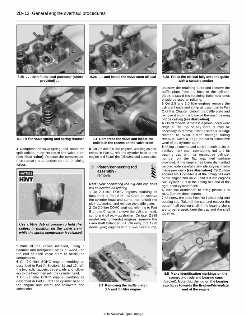
4 Compress the valve spring, and locate thesplit collets in the recess in the valve stem(see illustration). Release the compressor,then repeat the procedure on the remainingvalves.
5 With all the valves installed, using ahammer and interposed block of wood, tapthe end of each valve stem to settle thecomponents.6 On 2.0 litre SOHC engine, working asdescribed in Part A, Sections 11 and 12, refitthe hydraulic tappets, thrust pads and follow-ers to the head then refit the cylinder head.7 On 2.0 litre DOHC engine, working asdescribed in Part B, refit the cylinder head tothe engine and install the followers andcamshafts.
8 On 2.5 and 3.0 litre engines, working as des-cribed in Part C, refit the cylinder head to theengine and install the followers and camshafts.
9 Piston/connecting rodassembly - removal
4Note: New connecting rod big-end cap boltswill be needed on refitting1 On 2.0 litre SOHC engines, working asdescribed in Part A of this Chapter, removethe cylinder head and sump then unbolt thepick-up/strainer and remove the baffle plate.2 On 2.0 litre DOHC engines, referring to PartB of this Chapter, remove the cylinder head,sump and oil pick-up/strainer. On later (1998model year onwards) engines, remove thecrankshaft balancer unit. On early (pre 1998model year) engines with a two-piece sump,
unscrew the retaining bolts and remove thebaffle plate from the base of the cylinderblock; discard the retaining bolts new onesshould be used on refitting.3 On 2.5 and 3.0 litre engines remove thecylinder heads and sump as described in PartC of this Chapter. Unbolt the baffle plate andremove it from the base of the main bearingbridge casting (see illustration).4 On all models, if there is a pronounced wearridge at the top of any bore, it may benecessary to remove it with a scraper or ridgereamer, to avoid piston damage duringremoval. Such a ridge indicates excessivewear of the cylinder bore.5 Using a hammer and centre-punch, paint orsimilar, mark each connecting rod and itsbearing cap with its respective cylindernumber on the flat machined surfaceprovided; if the engine has been dismantledbefore, note carefully any identifying marksmade previously (see illustration). On 2.0 litreengines No 1 cylinder is at the timing belt endof the engine and on 2.5 and 3.0 litre enginesNo1 cylinder it is at the timing belt end of theright-hand cylinder bank.6 Turn the crankshaft to bring piston 1 toBDC (bottom dead centre).7 Unscrew the bolts from No 1 piston big-endbearing cap. Take off the cap and recover thebottom half bearing shell. If the bearing shellsare to be re-used, tape the cap and the shelltogether.
2D•12 General engine overhaul procedures
8.2b . . . then fit the seal protector (whereprovided) . . .
8.2c . . . and install the valve stem oil seal 8.2d Press the oil seal fully onto the guidewith a suitable socket
8.3 Fit the valve spring and spring retainer 8.4 Compress the valve and locate thecollets in the recess on the valve stem
9.3 Removing the baffle plate - 2.5 and 3.0 litre engine
9.5 Make identification markings on theconnecting rods and bearing caps
(circled). Note that the lug on the bearingcap faces towards the flywheel/driveplate
end of the engine
3510 Vauxhall/Opel Omega
Use a little dab of grease to hold thecollets in position on the valve stemwhile the spring compressor is released

Caution: On some engines, the connectingrod/bearing cap mating surfaces are notmachined flat; the big-end bearing capsare ‘cracked’ off from the rod duringproduction and left untouched to ensurethe cap and rod mate perfectly. Where thistype of connecting rod is fitted, great caremust be taken to ensure the matingsurfaces of the cap and rod are not markedor damaged in anyway. Any damage to themating surfaces will adversely affect thestrength of the connecting rod and couldlead to premature failure.8 Using a hammer handle, push the piston upthrough the bore, and remove it from the topof the cylinder block. Recover the bearingshell, and tape it to the connecting rod forsafe-keeping.9 Loosely refit the big-end cap to theconnecting rod, and secure with the bolts -this will help to keep the components in theircorrect order.10 On 2.0 litre engines, remove No 4 pistonassembly in the same way then turn thecrankshaft through 180° to bring pistons 2and 3 to BDC (bottom dead centre), andremove them in the same way.11 On 2.5 and 3.0 litre engines, remove theremaining five piston assemblies in the sameway, positioning the crankshaft as necessaryto gain access to the bearing cap bolts.
10 Crankshaft - removal 4
2.0 litre engineNote: New main bearing cap bolts will berequired on refitting.1 Remove the oil pump andflywheel/driveplate. Refer to Part A forinformation on SOHC engine and Part B forinformation on the DOHC engine.2 Remove the piston and connecting rodassemblies as described in Section 9. If nowork is to be done on the pistons andconnecting rods, unbolt the caps and pushthe pistons far enough up the bores that theconnecting rods are positioned clear of thecrankshaft journals.3 On earlier DOHC engines with a two-piecesump, evenly and progressively slacken theremaining bolts and remove the main bearingladder casting from the base of the block.Discard the retaining bolts; new ones must beused on refitting.4 Check the crankshaft endfloat as describedin Section 13, then proceed as follows.5 The main bearing caps should benumbered 1 to 5 from the timing belt end ofthe engine (see illustration). Note: On someengines the flywheel/driveplate end (number5) bearing cap may not be numbered but iseasily identified anyway. If the bearing capsare not marked, using a hammer and punch
or a suitable marker pen, number the capsfrom 1 to 5 from the timing belt end of theengine and mark each cap to indicate itscorrect fitted direction to avoid confusion onrefitting.6 Working in a diagonal sequence, evenlyand progressively slacken the ten mainbearing cap retaining bolts by half a turn at atime until all bolts are loose. Remove all bolts.7 Carefully remove each cap from thecylinder block, ensuring that the lower mainbearing shell remains in position in the cap(see illustration).8 Carefully lift out the crankshaft, taking carenot to displace the upper main bearing shells(see illustration). Remove the flywheel/driveplate end oil seal and discard it.9 Recover the upper bearing shells from thecylinder block, and tape them to theirrespective caps for safe-keeping (seeillustration).
2.5 and 3.0 litre enginesNote: New main bearing cap/bridge bolts willbe required on refitting.10 Remove the oil pump and flywheel/driveplate as described in Part C of thisChapter.11 Remove the piston and connecting rodassemblies as described in Section 9. If nowork is to be done on the pistons andconnecting rods, unbolt the caps and pushthe pistons far enough up the bores that theconnecting rods are positioned clear of thecrankshaft journals.
12 Check the crankshaft endfloat asdescribed in Section 13, then proceed asfollows.13 Prior to removal, check the main bearingbridge casting fitting mark is clearly visible.There should be an arrow on the castingwhich points towards the timing belt end ofthe engine.14 With the cylinder block upside down,slacken and remove the four bolts securingthe main bearing bridge casting to thecylinder block.15 Working in a diagonal sequence, evenlyand progressively slacken the eight mainbearing cap/bridge retaining bolts by half aturn at a time until all bolts are loose. Removethe bolts then lift off the bridge casting fromthe cylinder block.16 The main bearing caps should benumbered 1 to 3 from the timing belt end ofthe engine; the flywheel/driveplate endbearing cap is not numbered but is easilyidentified anyway. If the bearing caps are notmarked, using a hammer and punch or asuitable marker pen, number the caps from 1to 3 from the timing belt end of the engine andmark each cap to indicate its correct fitteddirection to avoid confusion on refitting.17 Carefully remove each cap from thecylinder block, ensuring that the lower mainbearing shell remains in position in the cap. Ifthe rear cap is a tight-fit, screw two M8 boltsinto the threaded holes and use the bolts topull the cap out (see illustration).18 Carefully lift out the crankshaft, takingcare not to displace the upper main bearing
General engine overhaul procedures 2D•13
2D
10.5 The main bearing caps should benumbered (No 1 cap shown)
10.7 Removing the centre (No 3) mainbearing cap. Note the thrust flangesincorporated into the bearing shell
10.8 Remove the crankshaft . . . 10.9 . . . and lift out the upper mainbearing shells from the cylinder block
3510 Vauxhall/Opel Omega

shells (see illustration). Remove theflywheel/driveplate end oil seal and discard it.19 Recover the upper bearing shells from thecylinder block, and tape them to theirrespective caps for safe-keeping.
11 Cylinder block - cleaning and inspection 4
Cleaning1 Remove all external components andelectrical switches/sensors from the block.For complete cleaning, the core plugs shouldideally be removed. On 2.0 litre engines thecore plugs are a press-fit; to remove a plug,drill a small hole then insert a self-tappingscrew into the hole and pull out the plug either
with a pair of grips or a slide hammer. On 2.5and 3.0 litre engines the core plugs arescrewed in position.2 Scrape all traces of gasket from the cylinderblock taking care not to damage thegasket/sealing surfaces.3 Remove all oil gallery plugs (where fitted).The plugs are usually very tight - they may haveto be drilled out, and the holes re-tapped. Usenew plugs when the engine is reassembled. On2.5 and 3.0 litre engines, it is recommendedthat the oil bypass valve is also removed; thevalve is located behind the oil filter (a new onewill be needed on refitting). To remove thebypass valve, cut a thread into the centre of thevalve bore with an M10 tap; use the finishing(blunt-ended) tap to ensure the valve isthreaded right up to the ball. Draw the valve outfrom the block using an M10 bolt and washersand a socket as a spacer (see illustrations).4 If any of the castings are extremely dirty, allshould be steam-cleaned.5 After the castings are returned, clean all oilholes and oil galleries one more time. Flush allinternal passages with warm water until thewater runs clear. Dry thoroughly, and apply alight film of oil to all mating surfaces, toprevent rusting. Also oil the cylinder bores. Ifyou have access to compressed air, use it tospeed up the drying process, and to blow outall the oil holes and galleries (see illustration).
Warning: Wear eye protectionwhen using compressed air!
6 If the castings are not very dirty, you can doan adequate cleaning job with hot (as hot as
you can stand!), soapy water and a stiff brush.Take plenty of time, and do a thorough job.Regardless of the cleaning method used, besure to clean all oil holes and galleries verythoroughly, and to dry all components well.Protect the cylinder bores as describedabove, to prevent rusting.7 All threaded holes must be clean, to ensureaccurate torque readings during reassembly.To clean the threads, run the correct-size tapinto each of the holes to remove rust,corrosion, thread sealant or sludge, and torestore damaged threads. If possible, usecompressed air to clear the holes of debrisproduced by this operation. A goodalternative is to inject aerosol-applied water-dispersant lubricant into each hole, using thelong spout usually supplied.
Warning: Wear eye protectionwhen cleaning out these holes inthis way!
8 Apply suitable sealant to the new oil galleryplugs, and insert them into the holes in theblock. Tighten them securely.9 If the engine is not going to be reassembledright away, cover it with a large plastic bag tokeep it clean; protect all mating surfaces andthe cylinder bores as described above, toprevent rusting.
Inspection10 Visually check the castings for cracks andcorrosion. Look for stripped threads in thethreaded holes. If there has been any historyof internal water leakage, it may be worthwhilehaving an engine overhaul specialist checkthe cylinder block/crankcase with specialequipment. If defects are found, have themrepaired if possible, or renew the assembly.11 Check the bore of each cylinder forscuffing and scoring.12 Measure the diameter of each cylinderbore at the top (just below the wear ridge),centre and bottom of the bore, both parallel tothe crankshaft axis and at right angles to it, sothat a total of six measurements are taken.Note that there are various size groups ofstandard bore diameter to allow formanufacturing tolerances; the size groupmarkings are stamped on the cylinder blockupper surface.13 Compare the results with theSpecifications at the beginning of this
2D•14 General engine overhaul procedures
10.17 If the rear cap is tight, screw two M8bolts into the cap and use them to work
the cap free
10.18 Removing the crankshaft - 2.5 and 3.0 litre engine
11.3a On 2.5 and 3.0 litre engines cut anM10 thread into the oil bypass valve . . .
11.3b . . . then use an M10 bolt and washerand a suitable socket . . .
11.3c . . . to draw the valve assembly outfrom the cylinder block
11.5 Use compressed air to blow out allthe cylinder block internal drillings and
oilways
3510 Vauxhall/Opel Omega

Chapter; if any measurement exceeds theservice limit specified, the cylinder block mustbe rebored if possible, or renewed and newpiston assemblies fitted.14 If the cylinder bores are badly scuffed orscored, or if they are excessively worn, out-of-round or tapered, or if the piston-to-boreclearances is excessive (see Section 12), thecylinder block must be rebored (if possible) orrenewed and new pistons fitted. Oversize (0.5mm) pistons are available for all engines.15 If the bores are in reasonably goodcondition and not worn to the specified limits,then the piston rings should be renewed. Ifthis is the case, the bores should be honed toallow the new rings to bed in correctly andprovide the best possible seal. Theconventional type of hone has spring-loadedstones, and is used with a power drill. You willalso need some paraffin (or honing oil) andrags. The hone should be moved up anddown the bore to produce a crosshatchpattern, and plenty of honing oil should beused. Ideally, the crosshatch lines shouldintersect at approximately a 60° angle. Do nottake off more material than is necessary toproduce the required finish. If new pistons arebeing fitted, the piston manufacturers mayspecify a finish with a different angle, so theirinstructions should be followed. Do notwithdraw the hone from the bore while it is stillbeing turned – stop it first. After honing abore, wipe out all traces of the honing oil. Ifequipment of this type is not available, or ifyou are not sure whether you are competentto undertake the task yourself, an engineoverhaul specialist will carry out the work atmoderate cost.16 On 2.5 and 3.0 litre engines, oncompletion fit a new oil bypass valve to thecylinder block and tap it fully into positionusing a hammer and tubular drift (a 15 mmsocket is ideal) (see illustrations).
12 Piston/connecting rodassembly - inspection
41 Before the inspection process can begin,the piston/connecting rod assemblies mustbe cleaned, and the original piston ringsremoved from the pistons.2 Carefully expand the old rings over the topof the pistons (see illustration). The use oftwo or three old feeler blades will be helpful inpreventing the rings dropping into emptygrooves. Be careful not to scratch the pistonwith the ends of the ring. The rings are brittle,and will snap if they are spread too far.They’re also very sharp - protect your handsand fingers. Note that the third (oil control)ring consists of a spacer and two side rails.Always remove the rings from the top of thepiston. Keep each set of rings with its piston ifthe old rings are to be re-used.3 Scrape away all traces of carbon from thetop of the piston. A hand-held wire brush (or a
piece of fine emery cloth) can be used, oncethe majority of the deposits have beenscraped away. The piston identificationmarkings should now be visible.4 Remove the carbon from the ring groovesin the piston, using an old ring. Break the ringin half to do this (be careful not to cut yourfingers - piston rings are sharp). Be careful toremove only the carbon deposits - do notremove any metal, and do not nick or scratchthe sides of the ring grooves.5 Once the deposits have been removed,clean the piston/connecting rod assemblywith paraffin or a suitable solvent, and drythoroughly. Make sure that the oil return holesin the ring grooves are clear.6 If the cylinder bores are not damaged orworn excessively, and if the cylinder blockdoes not need to be rebored (see Section 11),check the pistons as follows.7 Carefully inspect each piston for cracksaround the skirt, around the gudgeon pinholes, and at the piston ring ‘lands’ (betweenthe ring grooves).8 Look for scoring and scuffing on the pistonskirt, holes in the piston crown, and burnedareas at the edge of the crown. If the skirt isscored or scuffed, the engine may have beensuffering from overheating, and/or abnormalcombustion which caused excessively highoperating temperatures. The cooling andlubrication systems should be checkedthoroughly. Scorch marks on the sides of thepistons show that blow-by has occurred. Ahole in the piston crown, or burned areas atthe edge of the piston crown, indicates thatabnormal combustion (pre-ignition,knocking, or detonation) has been occurring.If any of the above problems exist, thecauses must be investigated and corrected,or the damage will occur again. The causesmay include incorrect ignition timing or afaulty injector.9 Corrosion of the piston, in the form ofpitting, indicates that coolant has beenleaking into the combustion chamber and/orthe crankcase. Again, the cause must becorrected, or the problem may persist in therebuilt engine.10 Measure the piston diameter at rightangles to the gudgeon pin axis; compare theresults with the Specifications at the
beginning of this Chapter. Note that there arevarious size groups of standard pistondiameter to allow for manufacturingtolerances; the size group markings arestamped on the piston crown.11 To measure the piston-to-bore clearance,either measure the bore (see Section 11) andpiston skirt as described and subtract the skirtdiameter from the bore measurement, orinsert each piston into its original bore, thenselect a feeler gauge blade and slip it into thebore along with the piston. The piston mustbe aligned exactly in its normal attitude, andthe feeler gauge blade must be between thepiston and bore, on one of the thrust faces,just up from the bottom of the bore. If theclearance is excessive, a new piston will berequired. If the piston binds at the lower endof the bore and is loose towards the top, thebore is tapered. If tight spots are encounteredas the piston/feeler gauge blade is rotated inthe bore, the bore is out-of-round.12 Repeat this procedure for the remainingpistons and cylinder bores. Any piston whichis worn beyond the specified limits must berenewed.13 Examine each connecting rod carefully forsigns of damage, such as cracks around thebig-end and small-end bearings. Check thatthe rod is not bent or distorted. Damage ishighly unlikely, unless the engine has beenseized or badly overheated. Detailed checkingof the connecting rod assembly can only becarried out by a Vauxhall dealer or enginerepair specialist with the necessaryequipment.
General engine overhaul procedures 2D•15
2D
11.16a On 2.5 and 3.0 litre engines, insertthe new bypass valve into the cylinder
block . . .
11.16b . . . and tap it fully into positionusing a hammer and socket
12.2 Using a feeler blade to remove apiston ring
3510 Vauxhall/Opel Omega

14 On 2.0 and 2.5 litre engines, the gudgeonpins are an interference fit in the connectingrod small-end bearing. Therefore, pistonand/or connecting rod renewal should beentrusted to a Vauxhall dealer or engine repairspecialist, who will have the necessary toolingto remove and install the gudgeon pins. If newpistons are to be fitted, ensure that thecorrect size group pistons are fitted to eachbore (see Section 12). Note: Vauxhall statethat the piston/connecting rod assembliesshould not be disassembled. If anycomponents requires renewal, then thecomplete assembly must be renewed. Do notfit a new piston to an old connecting rod orvice versa.15 On 3.0 litre engines, the gudgeon pins areof the floating type, secured in position by twocirclips. On these engines, the pistons andconnecting rods can be separated as follows.16 Using a small flat-bladed screwdriver,prise out the circlips, and push out thegudgeon pin. Hand pressure should besufficient to remove the pin. Identify the pistonand rod to ensure correct reassembly.Discard the circlips - new ones must be usedon refitting.17 Examine the gudgeon pin and connectingrod small-end bearing for signs of wear ordamage. Wear will require the renewal of boththe pin and connecting rod.18 The connecting rods themselves shouldnot be in need of renewal, unless seizure orsome other major mechanical failure hasoccurred. Check the alignment of the
connecting rods visually, and if the rods arenot straight, take them to an engine overhaulspecialist for a more detailed check.19 Examine all components, and obtain anynew parts from your Vauxhall dealer. If newpistons are purchased, they will be suppliedcomplete with gudgeon pins and circlips.Circlips can also be purchased individually.20 Assemble the piston and connecting rodso that the arrow on the piston crown ispointing away from the assembly mark whichis cast onto one side of the connecting rod, onthe top of the big-end bore (see illustrations).21 Apply a smear of clean engine oil to thegudgeon pin. Slide it into the piston andthrough the connecting rod small-end. Checkthat the piston pivots freely on the rod, thensecure the gudgeon pin in position with twonew circlips, ensuring that each circlip iscorrectly located in its groove in the piston.
13 Crankshaft - inspection 4
Checking crankshaft endfloat1 If the crankshaft endfloat is to be checked,this must be done when the crankshaft is stillinstalled in the cylinder block, but is free tomove (see Section 10).2 Check the endfloat using a dial gauge incontact with the end of the crankshaft (seeillustration). Push the crankshaft fully one way,and then zero the gauge. Push the crankshaftfully the other way, and check the endfloat. The
result can be compared with the specifiedamount, and will give an indication as towhether new main bearing shells are required.3 If a dial gauge is not available, feelergauges can be used (see illustration). Firstpush the crankshaft fully towards theflywheel/driveplate end of the engine, thenuse feeler gauges to measure the gapbetween the web of the crankpin and the sideof thrustwasher which is incorporated intonumber 3 main bearing shells on 2.0 litreengines and number 4 shell on 2.5 and 3.0litre engines.
Inspection4 Clean the crankshaft using paraffin or asuitable solvent, and dry it, preferably withcompressed air if available. Be sure to cleanthe oil holes with a pipe cleaner or similarprobe, to ensure that they are not obstructed.
Warning: Wear eye protectionwhen using compressed air.
5 Check the main and big-end bearingjournals for uneven wear, scoring, pitting andcracking.6 Big-end bearing wear is accompanied bydistinct metallic knocking when the engine isrunning (particularly noticeable when theengine is pulling from low speed) and someloss of oil pressure.7 Main bearing wear is accompanied bysevere engine vibration and rumble - gettingprogressively worse as engine speedincreases - and again by loss of oil pressure.8 Check the bearing journal for roughness byrunning a finger lightly over the bearingsurface. Any roughness (which will beaccompanied by obvious bearing wear)indicates that the crankshaft requiresregrinding (where possible) or renewal.9 Check for burrs around the crankshaft oilholes (the holes are usually chamfered, soburrs should not be a problem unlessregrinding has been carried out carelessly).Remove any burrs with a fine file or scraper,and thoroughly clean the oil holes asdescribed previously.10 Using a micrometer, measure the diameterof the main and big-end bearing journals, andcompare the results with the Specifications(see illustration). By measuring the diameter
2D•16 General engine overhaul procedures
12.20a Ensure the piston and connectingrod are assembled so the arrow on thepiston crown (circled) is pointing away
from . . .
12.20b . . . the assembly mark (circled) onthe side of the connecting rod
13.2 Checking crankshaft endfloat with adial gauge
13.3 Using a feeler blade to measurecrankshaft endfloat (2.0 litre engine shown)
13.10 Using a micrometer to measure amain bearing journal
3510 Vauxhall/Opel Omega
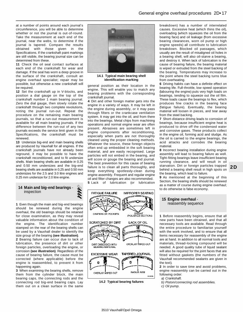
at a number of points around each journal’scircumference, you will be able to determinewhether or not the journal is out-of-round.Take the measurement at each end of thejournal, near the webs, to determine if thejournal is tapered. Compare the resultsobtained with those given in theSpecifications. If the crankshaft paint markingsare still visible, the bearing journal size can bedetermined from these.11 Check the oil seal contact surfaces ateach end of the crankshaft for wear anddamage. If the seal has worn a deep groove inthe surface of the crankshaft, consult anengine overhaul specialist; repair may bepossible, but otherwise a new crankshaft willbe required.12 Set the crankshaft up in V-blocks, andposition a dial gauge on the top of thecrankshaft number 1 main bearing journal.Zero the dial gauge, then slowly rotate thecrankshaft through two complete revolutions,noting the journal run-out. Repeat theprocedure on the remaining main bearingjournals, so that a run-out measurement isavailable for all main bearing journals. If thedifference between the run-out of any twojournals exceeds the service limit given in theSpecifications, the crankshaft must berenewed.13 Undersize big-end and main bearing shellsare produced by Vauxhall for all engines. If thecrankshaft journals have not already beenreground, it may be possible to have thecrankshaft reconditioned, and to fit undersizeshells. Main bearing shells are available in 0.25and 0.50 mm undersizes and the big-endbearing shells are available in 0.25 and 0.50 mmundersizes for the 2.5 and 3.0 litre engines and0.25 mm undersize for 2.0 litre engine.
14 Main and big-end bearings -inspection 4
1 Even though the main and big-end bearingsshould be renewed during the engineoverhaul, the old bearings should be retainedfor close examination, as they may revealvaluable information about the condition ofthe engine. The identification numberstamped on the rear of the bearing shells canbe used by a Vauxhall dealer to identify thesize group of the bearing (see illustration).2 Bearing failure can occur due to lack oflubrication, the presence of dirt or otherforeign particles, overloading the engine, orcorrosion (see illustration). Regardless of thecause of bearing failure, the cause must becorrected (where applicable) before theengine is reassembled, to prevent it fromhappening again.3 When examining the bearing shells, removethem from the cylinder block, the mainbearing caps, the connecting rods and theconnecting rod big-end bearing caps. Laythem out on a clean surface in the same
general position as their location in theengine. This will enable you to match anybearing problems with the correspondingcrankshaft journal.4 Dirt and other foreign matter gets into theengine in a variety of ways. It may be left inthe engine during assembly, or it may passthrough filters or the crankcase ventilationsystem. It may get into the oil, and from thereinto the bearings. Metal chips from machiningoperations and normal engine wear are oftenpresent. Abrasives are sometimes left inengine components after reconditioning,especially when parts are not thoroughlycleaned using the proper cleaning methods.Whatever the source, these foreign objectsoften end up embedded in the soft bearingmaterial, and are easily recognised. Largeparticles will not embed in the bearing, andwill score or gouge the bearing and journal.The best prevention for this cause of bearingfailure is to clean all parts thoroughly, andkeep everything spotlessly-clean duringengine assembly. Frequent and regular engineoil and filter changes are also recommended.5 Lack of lubrication (or lubrication
breakdown) has a number of interrelatedcauses. Excessive heat (which thins the oil),overloading (which squeezes the oil from thebearing face) and oil leakage (from excessivebearing clearances, worn oil pump or highengine speeds) all contribute to lubricationbreakdown. Blocked oil passages, whichusually are the result of misaligned oil holes ina bearing shell, will also oil-starve a bearing,and destroy it. When lack of lubrication is thecause of bearing failure, the bearing materialis wiped or extruded from the steel backing ofthe bearing. Temperatures may increase tothe point where the steel backing turns bluefrom overheating.6 Driving habits can have a definite effect onbearing life. Full-throttle, low-speed operation(labouring the engine) puts very high loads onbearings, tending to squeeze out the oil film.These loads cause the bearings to flex, whichproduces fine cracks in the bearing face(fatigue failure). Eventually, the bearingmaterial will loosen in pieces, and tear awayfrom the steel backing.7 Short-distance driving leads to corrosion ofbearings, because insufficient engine heat isproduced to drive off the condensed waterand corrosive gases. These products collectin the engine oil, forming acid and sludge. Asthe oil is carried to the engine bearings, theacid attacks and corrodes the bearingmaterial.8 Incorrect bearing installation during engineassembly will lead to bearing failure as well.Tight-fitting bearings leave insufficient bearingrunning clearance, and will result in oilstarvation. Dirt or foreign particles trappedbehind a bearing shell result in high spots onthe bearing, which lead to failure.9 As mentioned at the beginning of thisSection, the bearing shells should be renewedas a matter of course during engine overhaul;to do otherwise is false economy.
15 Engine overhaul - reassembly sequence
1 Before reassembly begins, ensure that allnew parts have been obtained, and that allnecessary tools are available. Read throughthe entire procedure to familiarise yourselfwith the work involved, and to ensure that allitems necessary for reassembly of the engineare at hand. In addition to all normal tools andmaterials, thread-locking compound will beneeded. A good quality tube of liquid sealantwill also be required for the joint faces that arefitted without gaskets (the numbers of theVauxhall recommended sealants are given inthe text).2 In order to save time and avoid problems,engine reassembly can be carried out in thefollowing order:a) Crankshaft.b) Piston/connecting rod assemblies.c) Oil pump.
General engine overhaul procedures 2D•17
2D
14.1 Typical main bearing shellidentification marking
14.2 Typical bearing failures
3510 Vauxhall/Opel Omega

d) Sump.e) Flywheel/driveplate.f) Cylinder head(s).g) Timing belt tensioner and sprockets, and
belts.h) Inlet and exhaust manifolds (Chapter 4A).i) Engine external components.
3 At this stage, all engine components shouldbe absolutely clean and dry, with all faultsrepaired. The components should be laid out(or in individual containers) on a completelyclean work surface.
16 Piston rings - refitting 4
1 Before fitting new piston rings, the ring endgaps must be checked as follows.2 Lay out the piston/connecting rodassemblies and the new piston ring sets, sothat the ring sets will be matched with thesame piston and cylinder during the end gapmeasurement and subsequent enginereassembly.3 Insert the top ring into the first cylinder, andpush it down the bore using the top of thepiston. This will ensure that the ring remainssquare with the cylinder walls. Push the ring
down into the bore until it is positioned 15 to20 mm down from the top edge of the bore,then withdraw the piston.4 Measure the end gap using feeler gauges,and compare the measurements with thefigures given in the Specifications (seeillustration).5 If the gap is too small (unlikely if genuineVauxhall parts are used), it must be enlarged,or the ring ends may contact each otherduring engine operation, causing seriousdamage. Ideally, new piston rings providingthe correct end gap should be fitted. As a lastresort, the end gap can be increased by filingthe ring ends very carefully with a fine file.Mount the file in a vice with soft jaws, slip thering over the file with the ends contacting thefile face, and slowly move the ring to removematerial from the ends. Take care, as pistonrings are sharp, and are easily broken.6 With new piston rings, it is unlikely that theend gap will be too large. If the gaps are toolarge, check that you have the correct ringsfor your engine and for the particular cylinderbore size.7 Repeat the checking procedure for eachring in the first cylinder, and then for the ringsin the remaining cylinders. Remember to keeprings, pistons and cylinders matched up.8 Once the ring end gaps have been checkedand if necessary corrected, the rings can befitted to the pistons.9 Fit the piston rings using the sametechnique as for removal. Fit the bottom (oilcontrol) spacer first then install both the siderails, noting that both the spacer and side railscan be installed either way up.10 The second and top compression ringsare different and can be identified by theircross-sections; the top ring is square whilstthe second ring is tapered. Fit the second andtop compression rings ensuring that each ringis fitted the correct way up with itsidentification (TOP) mark uppermost. Note:Always follow any instructions supplied withthe new piston ring sets - differentmanufacturers may specify differentprocedures. Do not mix up the top andsecond compression rings. On some enginesthe top ring will not have an identificationmarking and can be fitted either way up.11 With the piston rings correctly installed,check that each ring is free to rotate easily in
its groove. Check the ring-to-grooveclearance of each ring using feeler gaugesand check that the clearance is within thespecified range then position the ring endgaps as shown (see illustrations).
17 Crankshaft - refitting and main bearingrunning clearance check
4Note: It is recommended that new mainbearing shells are fitted regardless of thecondition of the original ones.
Selection of bearing shells1 Although the original bearing shells fitted atthe factory maybe of various grades, allreplacement bearing shells sold are of thesame grade. Vauxhall supply both standardsize bearing shells and undersize shells foruse when the crankshaft has been reground.The required size of shell required can bedetermined by measuring the crankshaftjournals (see Section 13).
Main bearing running clearancecheck2 Clean the backs of the bearing shells andthe bearing locations in both the cylinderblock and the main bearing caps.3 Press the bearing shells into their locations,ensuring that the tab on each shell engages inthe notch in the cylinder block or main bearingcap (see illustration). If the original bearingshells are being used for the check ensurethey are refitted in their original locations.When fitting new shells on 2.5 and 3.0 litreengines, note that No1 bearing is wider thanNo2 and 3 and that the grooved shell of No2and 3 bearing should be fitted in the upperlocation. The clearance can be checked ineither of two ways.4 One method (which will be difficult toachieve without a range of internalmicrometers or internal/external expandingcalipers) is to refit the main bearing caps tothe cylinder block, with bearing shells inplace. With the cap retaining bolts correctlytightened (use the original bolts for the check,not the new ones), measure the internaldiameter of each assembled pair of bearing
2D•18 General engine overhaul procedures
16.4 Measuring a piston ring end gapusing a feeler gauge
16.11a Checking the piston ring-to-grooveclearance using a feeler gauge
16.11b Piston ring end gap positions
I Top and second compression ringsII Oil control ring side rails
17.3 Fit each main bearing shell makingsure its tab is correctly seated in the notch
(arrowed)
3510 Vauxhall/Opel Omega
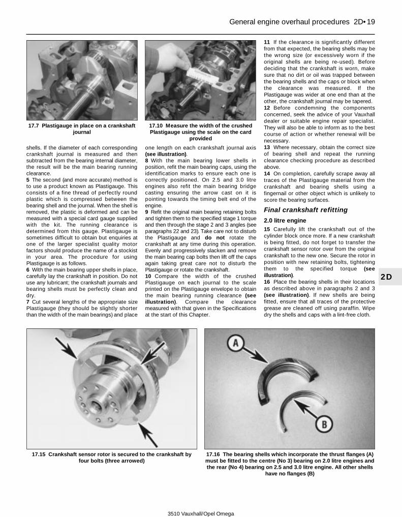
shells. If the diameter of each correspondingcrankshaft journal is measured and thensubtracted from the bearing internal diameter,the result will be the main bearing runningclearance.5 The second (and more accurate) method isto use a product known as Plastigauge. Thisconsists of a fine thread of perfectly roundplastic which is compressed between thebearing shell and the journal. When the shell isremoved, the plastic is deformed and can bemeasured with a special card gauge suppliedwith the kit. The running clearance isdetermined from this gauge. Plastigauge issometimes difficult to obtain but enquiries atone of the larger specialist quality motorfactors should produce the name of a stockistin your area. The procedure for usingPlastigauge is as follows.6 With the main bearing upper shells in place,carefully lay the crankshaft in position. Do notuse any lubricant; the crankshaft journals andbearing shells must be perfectly clean anddry.7 Cut several lengths of the appropriate sizePlastigauge (they should be slightly shorterthan the width of the main bearings) and place
one length on each crankshaft journal axis(see illustration).8 With the main bearing lower shells inposition, refit the main bearing caps, using theidentification marks to ensure each one iscorrectly positioned. On 2.5 and 3.0 litreengines also refit the main bearing bridgecasting ensuring the arrow cast on it ispointing towards the timing belt end of theengine.9 Refit the original main bearing retaining boltsand tighten them to the specified stage 1 torqueand then through the stage 2 and 3 angles (seeparagraphs 22 and 23). Take care not to disturbthe Plastigauge and do not rotate thecrankshaft at any time during this operation.Evenly and progressively slacken and removethe main bearing cap bolts then lift off the capsagain taking great care not to disturb thePlastigauge or rotate the crankshaft.10 Compare the width of the crushedPlastigauge on each journal to the scaleprinted on the Plastigauge envelope to obtainthe main bearing running clearance (seeillustration). Compare the clearancemeasured with that given in the Specificationsat the start of this Chapter.
11 If the clearance is significantly differentfrom that expected, the bearing shells may bethe wrong size (or excessively worn if theoriginal shells are being re-used). Beforedeciding that the crankshaft is worn, makesure that no dirt or oil was trapped betweenthe bearing shells and the caps or block whenthe clearance was measured. If thePlastigauge was wider at one end than at theother, the crankshaft journal may be tapered.12 Before condemning the componentsconcerned, seek the advice of your Vauxhalldealer or suitable engine repair specialist.They will also be able to inform as to the bestcourse of action or whether renewal will benecessary.13 Where necessary, obtain the correct sizeof bearing shell and repeat the runningclearance checking procedure as describedabove.14 On completion, carefully scrape away alltraces of the Plastigauge material from thecrankshaft and bearing shells using afingernail or other object which is unlikely toscore the bearing surfaces.
Final crankshaft refitting
2.0 litre engine15 Carefully lift the crankshaft out of thecylinder block once more. If a new crankshaftis being fitted, do not forget to transfer thecrankshaft sensor rotor over from the originalcrankshaft to the new one. Secure the rotor inposition with new retaining bolts, tighteningthem to the specified torque (seeillustration).16 Place the bearing shells in their locationsas described above in paragraphs 2 and 3(see illustration). If new shells are beingfitted, ensure that all traces of the protectivegrease are cleaned off using paraffin. Wipedry the shells and caps with a lint-free cloth.
General engine overhaul procedures 2D•19
2D
17.7 Plastigauge in place on a crankshaftjournal
17.10 Measure the width of the crushedPlastigauge using the scale on the card
provided
3510 Vauxhall/Opel Omega
17.15 Crankshaft sensor rotor is secured to the crankshaft byfour bolts (three arrowed)
17.16 The bearing shells which incorporate the thrust flanges (A)must be fitted to the centre (No 3) bearing on 2.0 litre engines andthe rear (No 4) bearing on 2.5 and 3.0 litre engine. All other shells
have no flanges (B)
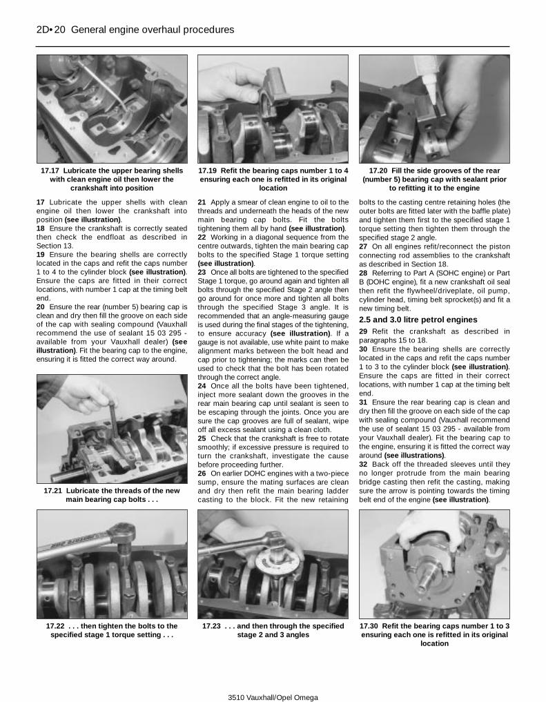
17 Lubricate the upper shells with cleanengine oil then lower the crankshaft intoposition (see illustration).18 Ensure the crankshaft is correctly seatedthen check the endfloat as described inSection 13.19 Ensure the bearing shells are correctlylocated in the caps and refit the caps number1 to 4 to the cylinder block (see illustration).Ensure the caps are fitted in their correctlocations, with number 1 cap at the timing beltend.20 Ensure the rear (number 5) bearing cap isclean and dry then fill the groove on each sideof the cap with sealing compound (Vauxhallrecommend the use of sealant 15 03 295 -available from your Vauxhall dealer) (seeillustration). Fit the bearing cap to the engine,ensuring it is fitted the correct way around.
21 Apply a smear of clean engine to oil to thethreads and underneath the heads of the newmain bearing cap bolts. Fit the boltstightening them all by hand (see illustration).22 Working in a diagonal sequence from thecentre outwards, tighten the main bearing capbolts to the specified Stage 1 torque setting(see illustration).23 Once all bolts are tightened to the specifiedStage 1 torque, go around again and tighten allbolts through the specified Stage 2 angle thengo around for once more and tighten all boltsthrough the specified Stage 3 angle. It isrecommended that an angle-measuring gaugeis used during the final stages of the tightening,to ensure accuracy (see illustration). If agauge is not available, use white paint to makealignment marks between the bolt head andcap prior to tightening; the marks can then beused to check that the bolt has been rotatedthrough the correct angle.24 Once all the bolts have been tightened,inject more sealant down the grooves in therear main bearing cap until sealant is seen tobe escaping through the joints. Once you aresure the cap grooves are full of sealant, wipeoff all excess sealant using a clean cloth.25 Check that the crankshaft is free to rotatesmoothly; if excessive pressure is required toturn the crankshaft, investigate the causebefore proceeding further.26 On earlier DOHC engines with a two-piecesump, ensure the mating surfaces are cleanand dry then refit the main bearing laddercasting to the block. Fit the new retaining
bolts to the casting centre retaining holes (theouter bolts are fitted later with the baffle plate)and tighten them first to the specified stage 1torque setting then tighten them through thespecified stage 2 angle.27 On all engines refit/reconnect the pistonconnecting rod assemblies to the crankshaftas described in Section 18.28 Referring to Part A (SOHC engine) or PartB (DOHC engine), fit a new crankshaft oil sealthen refit the flywheel/driveplate, oil pump,cylinder head, timing belt sprocket(s) and fit anew timing belt.
2.5 and 3.0 litre petrol engines29 Refit the crankshaft as described inparagraphs 15 to 18.30 Ensure the bearing shells are correctlylocated in the caps and refit the caps number1 to 3 to the cylinder block (see illustration).Ensure the caps are fitted in their correctlocations, with number 1 cap at the timing beltend.31 Ensure the rear bearing cap is clean anddry then fill the groove on each side of the capwith sealing compound (Vauxhall recommendthe use of sealant 15 03 295 - available fromyour Vauxhall dealer). Fit the bearing cap tothe engine, ensuring it is fitted the correct wayaround (see illustrations).32 Back off the threaded sleeves until theyno longer protrude from the main bearingbridge casting then refit the casting, makingsure the arrow is pointing towards the timingbelt end of the engine (see illustration).
2D•20 General engine overhaul procedures
17.17 Lubricate the upper bearing shellswith clean engine oil then lower the
crankshaft into position
17.19 Refit the bearing caps number 1 to 4ensuring each one is refitted in its original
location
17.20 Fill the side grooves of the rear(number 5) bearing cap with sealant prior
to refitting it to the engine
17.21 Lubricate the threads of the newmain bearing cap bolts . . .
17.30 Refit the bearing caps number 1 to 3ensuring each one is refitted in its original
location
17.22 . . . then tighten the bolts to thespecified stage 1 torque setting . . .
17.23 . . . and then through the specifiedstage 2 and 3 angles
3510 Vauxhall/Opel Omega
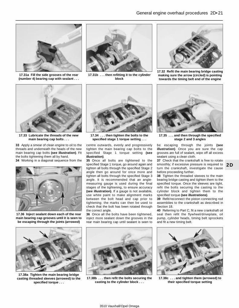
33 Apply a smear of clean engine to oil to thethreads and underneath the heads of the newmain bearing cap bolts (see illustration). Fitthe bolts tightening them all by hand.34 Working in a diagonal sequence from the
centre outwards, evenly and progressivelytighten the main bearing cap bolts to thespecified Stage 1 torque setting (seeillustration).35 Once all bolts are tightened to thespecified Stage 1 torque, go around again andtighten all bolts through the specified Stage 2angle then go around for once more andtighten all bolts through the specified Stage 3angle. It is recommended that an angle-measuring gauge is used during the finalstages of the tightening, to ensure accuracy(see illustration). If a gauge is not available,use white paint to make alignment marksbetween the bolt head and cap prior totightening; the marks can then be used tocheck that the bolt has been rotated throughthe correct angle.36 Once all the bolts have been tightened,inject more sealant down the grooves in therear main bearing cap until sealant is seen to
be escaping through the joints (seeillustration). Once you are sure the capgrooves are full of sealant, wipe off all excesssealant using a clean cloth.37 Check that the crankshaft is free to rotatesmoothly; if excessive pressure is required toturn the crankshaft, investigate the causebefore proceeding further.38 Tighten the threaded sleeves to the mainbearing bridge casting and tighten them to thespecified torque. Once the sleeves are tight,refit the bolts securing the casting to thecylinder block and tighten them to thespecified torque (see illustrations).39 Refit/reconnect the piston connecting rodassemblies to the crankshaft as described inSection 18.40 Referring to Part C, fit a new crankshaft oilseal then refit the flywheel/driveplate, oilpump, cylinder heads, timing belt sprocketsand fit a new timing belt.
General engine overhaul procedures 2D•21
2D
17.31a Fill the side grooves of the rear(number 4) bearing cap with sealant . . .
17.31b . . . then refitting it to the cylinderblock
17.32 Refit the main bearing bridge castingmaking sure the arrow (circled) is pointingtowards the timing belt end of the engine
17.38a Tighten the main bearing bridgecasting threaded sleeves (arrowed) to the
specified torque . . .
17.36 Inject sealant down each of the rearmain bearing cap grooves until it is seen to
be escaping through the joints (arrowed)
17.38b . . . then refit the bolts securing thecasting to the cylinder block . . .
17.38c . . . and tighten them (arrowed) totheir specified torque setting
17.33 Lubricate the threads of the newmain bearing cap bolts . . .
17.34 . . . then tighten the bolts to thespecified stage 1 torque setting . . .
17.35 . . . and then through the specifiedstage 2 and 3 angles
3510 Vauxhall/Opel Omega

18 Piston/connecting rodassembly - refitting and big-end running clearance check
4Note: It is recommended that new piston ringsand big-end bearing shells are fittedregardless of the condition of the originalones.
Selection of bearing shells1 Although the original bearing shells fitted atthe factory maybe of various grades, allreplacement bearing shells sold are of thesame grade. Vauxhall supply both standardsize bearing shells and undersize shells foruse when the crankshaft has been reground.The required size of shell required can bedetermined by measuring the crankshaftjournals (see Section 13).
Big-end bearing runningclearance check2 Clean the backs of the bearing shells andthe bearing locations in both the connectingrod and bearing cap.3 Press the bearing shells into their locations,ensuring that the tab on each shell engages inthe notch in the connecting rod and cap (see
illustration). If the original bearing shells arebeing used for the check ensure they arerefitted in their original locations. The clearancecan be checked in either of two ways.4 One method is to refit the big-end bearingcap to the connecting rod, with bearing shellsin place. With the cap retaining bolts (use theoriginal bolts for the check) correctly tightened,use an internal micrometer or vernier caliper tomeasure the internal diameter of eachassembled pair of bearing shells. If thediameter of each corresponding crankshaftjournal is measured and then subtracted fromthe bearing internal diameter, the result will bethe big-end bearing running clearance.5 The second method is to use Plastigaugeas described in Section 17, paragraphs 5 to14. Place a strand of Plastigauge on each(cleaned) crankpin journal and refit the (clean)piston/connecting rod assemblies, shells andbig-end bearing caps. Tighten the bolts (seeparagraphs 13 - use the original bolts for thecheck) correctly taking care not to disturb thePlastigauge. Dismantle the assemblieswithout rotating the crankshaft and use thescale printed on the Plastigauge envelope toobtain the big-end bearing running clearance.On completion of the measurement, carefullyscrape off all traces of Plastigauge from thejournal and shells using a fingernail or otherobject which will not score the components.
Final piston/connecting rodassembly refitting6 Ensure the bearing shells are correctlyrefitted as described above in paragraphs 2and 3. If new shells are being fitted, ensurethat all traces of the protective grease arecleaned off using paraffin. Wipe dry the shellsand connecting rods with a lint-free cloth.7 Lubricate the bores, the pistons and pistonrings then lay out each piston/connecting rodassembly in its respective position.8 Starting with assembly number 1, makesure that the piston rings are still spaced asdescribed in Section 16, then clamp them in
position with a piston ring compressor (seeillustration).9 Insert the piston/connecting rod assemblyinto the top of cylinder No 1, ensuring that thearrow marking on the piston crown is pointingtowards the timing belt end of the engine.Using a block of wood or hammer handleagainst the piston crown, tap the assemblygently (do not force it) into the cylinder untilthe piston crown is flush with the top of thecylinder (see illustration). As the piston isfitted make sure the connecting rod lower endremains correctly aligned with the crankshaftto avoid damage.10 Taking care not to mark the cylinder bore,liberally lubricate the crankpin and bothbearing shells, then pull the piston/connectingrod assembly down the bore and onto thecrankpin.11 Ensure the connecting rod and bearingcap mating surfaces are completely clean anddry; this is most important on engines wherethe bearing caps are ‘cracked’ off of the rod.12 Refit the big-end bearing cap, using themarkings to ensure it is fitted the correct wayaround (the lug on the bearing cap baseshould be facing the flywheel/driveplate endof the engine), then screw in the new retainingbolts (see illustrations).
2D•22 General engine overhaul procedures
18.9 Insert the piston into the correctbore, tapping it gently into position with
the handle of a hammer
18.12a Refit the bearing cap making surethe lug is facing towards the
flywheel/driveplate end of the engine . . .
3510 Vauxhall/Opel Omega
18.3 Fit the bearing shells to the connecting rod and cap makingsure their tabs are correctly seated in the cutouts
18.8 Ensure the piston ring end gaps are correctly positionedthen clamp them in position with a ring compressor

13 Tighten both bearing cap bolts to thespecified Stage 1 torque setting then tightenthem through the specified Stage 2 angle, andfinally through the specified Stage 3 angle. Itis recommended that an angle-measuringgauge is used during the final stages of thetightening, to ensure accuracy (seeillustrations). If a gauge is not available, usewhite paint to make alignment marks betweenthe bolt head and cap prior to tightening; themarks can then be used to check that the bolthas been rotated through the correct angle.14 Refit the remaining piston and connectingrod assemblies in the same way.15 Rotate the crankshaft, and check that itturns freely, with no signs of binding or tightspots.16 On 2.0 litre SOHC engines, working asdescribed in Part A of this Chapter, fit thebaffle plate, oil pump pick-up/strainer andsump to the cylinder block then refit thecylinder head.17 On 2.0 litre DOHC engines carry out thefollowing:a) On early (pre 1998 model year) engines
with a two-piece sump, refit the baffleplate to the main bearing ladder castingand screw in the new retaining bolts.Working in a diagonal sequence from thecentre outwards, tighten the bolts first tothe specified stage 1 torque and thentighten them through the specified stage2 angle.
b) On later engines refit the crankshaftbalancer unit as described in Part B.
c) On all engines refit the oil pump pick-up/strainer and sump then refit thecylinder head as described in Part B.
18 On 2.5 and 3.0 litre engines refit the baffleplate to the base of the main bearing bridgecasting and tighten its retaining bolts to thespecified torque (see illustration). Working asdescribed in Part C of this Chapter, refit thesump then install the cylinder heads.
19 Engine - initial start up after overhaul
1 With the engine refitted in the vehicle,double-check the engine oil and coolantlevels. Make a final check that everything hasbeen reconnected, and that there are no toolsor rags left in the engine compartment.2 Ensure the ignition is switched off thendisable the ignition system by disconnectingthe wiring connector from the DIS module(see Chapter 5A) and the fuel system byremoving the fuel pump relay from the enginecompartment relay box (see Chapter 4A,Section 13).3 Turn the engine on the starter until the oilpressure warning light goes out then stop.Ensure the ignition is switched off thensecurely refit the relay and reconnect thewiring connector.4 Start the engine as normal noting that thismay take a little longer than usual, due to the fuelsystem components having been disturbed.
5 While the engine is idling, check for fuel,water and oil leaks. Don’t be alarmed if thereare some odd smells and smoke from partsgetting hot and burning off oil deposits.6 Assuming all is well, keep the engine idlinguntil hot water is felt circulating through thetop hose, then switch off the engine.7 Allow the engine to cool then recheck theoil and coolant levels as described in Weeklychecks, and top-up as necessary.8 If new pistons, rings or crankshaft bearingshave been fitted, the engine must be treatedas new, and run-in for the first 500 miles (800km). Do not operate the engine at full-throttle,or allow it to labour at low engine speeds inany gear. It is recommended that the oil andfilter be changed at the end of this period.
General engine overhaul procedures 2D•23
2D
18.12b . . . and screw in the new retainingbolts
18.13a Tighten both bolts to the specifiedstage 1 torque setting . . .
18.13b . . . then tighten them through thespecified stage 2 and 3 angles
18.18 On 2.5 and 3.0 litre engines, refit thebaffle plate and tighten its retaining bolts
to the specified torque
3510 Vauxhall/Opel Omega
3510 Vauxhall/Opel Omega
3•1
3
Chapter 3Cooling, heating and ventilation systems
System typeAll models . . . . . . . . . . . . . . . . . . . . . . . . . . . . . . . . . . . . . . . . . . . . . . . . Pressurised, with cross-flow radiator, centrifugal water pump driven
by timing belt, bypass thermostat, and remote expansion tank.Thermostatically controlled electric main cooling fan, with one or twoauxiliary electric cooling fans, depending on specification.
ThermostatOpening commences . . . . . . . . . . . . . . . . . . . . . . . . . . . . . . . . . . . . . . . 92ºC (198ºF)Fully open . . . . . . . . . . . . . . . . . . . . . . . . . . . . . . . . . . . . . . . . . . . . . . . . 107ºC (225ºF)
CoolantType . . . . . . . . . . . . . . . . . . . . . . . . . . . . . . . . . . . . . . . . . . . . . . . . . . . . Refer to Weekly checksCapacity . . . . . . . . . . . . . . . . . . . . . . . . . . . . . . . . . . . . . . . . . . . . . . . . . Refer to Chapter 1
Air conditioning system - description and precautions . . . . . . . . . . . 11Air conditioning system components - removal and refitting . . . . . . 12Antifreeze mixture - general . . . . . . . . . . . . . . . . . . .See Weekly checksBlower motor and series resistor - removal and refitting . . . . . . . . . 10Coolant pump - removal and refitting . . . . . . . . . . . . . . . . . . . . . . . . 5Cooling system - draining, flushing and refilling . . . . . . .see Chapter 1Electric cooling fans - removal and refitting . . . . . . . . . . . . . . . . . . . 3Electronic Climate Control (ECC) components - removal and
refitting . . . . . . . . . . . . . . . . . . . . . . . . . . . . . . . . . . . . . . . . . . . . . . 13
Expansion tank - removal and refitting . . . . . . . . . . . . . . . . . . . . . . . 6General description . . . . . . . . . . . . . . . . . . . . . . . . . . . . . . . . . . . . . . 1Heater control system components - removal and refitting . . . . . . . 8Heater matrix - removal and refitting . . . . . . . . . . . . . . . . . . . . . . . . . 9Pollen filter - renewal . . . . . . . . . . . . . . . . . . . . . . . . . . . .see Chapter 1Radiator - removal and refitting . . . . . . . . . . . . . . . . . . . . . . . . . . . . . 2Temperature gauge sender unit - removal and refitting . . . . . . . . . . 7Thermostat - removal, testing and refitting . . . . . . . . . . . . . . . . . . . . 4
Specifications
Contents
Easy, suitable fornovice with littleexperience
Fairly easy, suitablefor beginner withsome experience
Fairly difficult,suitable for competentDIY mechanic
Difficult, suitable forexperienced DIYmechanic
Very difficult,suitable for expert DIYor professional
Degrees of difficulty
54321

1 General description
1 The cooling system comprises a radiator,timing belt driven coolant pump (dependingon engine), a waxstat-type bypassthermostat, and a remotely-mounted plasticexpansion tank. A thermostatically-controlledelectric cooling fan is fitted to all models,between the front of the engine and theradiator. An auxiliary cooling fan is also fitted,in front of the radiator. Models with airconditioning also have a second electricauxiliary cooling fan, to cope with the extrademand of cooling the refrigerant condenser.2 Cold water from the coolant pump is forcedaround the cylinder block, cylinder head andheater matrix during the warm up cycle. When
the engine reaches a predeterminedtemperature, the thermostat starts to openand the coolant then circulates through theradiator via a transfer pipe, to provide extracooling. The main cooling fan is controlled bythe temperature of air behind the radiator.
2 Radiator -removal and refitting 3
Removal
Models with 6-cylinder engines1 Ensure that the engine has cooledcompletely before starting work. Drain thecooling system as described in Chapter 1.2 Remove the screws and lift out the radiatorupper cover panel (see illustration).
3 Disconnect the negative and positive cablesfrom the battery terminals, then remove thebattery as described in Chapter 5A.4 Refer to Chapter 4A and remove multi-ramair intake pre-volume chamber.5 Disconnect the wiring from cooling fanthermo-switches, secondary air-cut-off valve,and auxiliary coolant pump (as applicable)(see illustrations). Label each connectorcarefully, to aid correct refitting.6 Disconnect all coolant hoses from theradiator; these include the expansion tankhose, the radiator top and bottom hoses, andthe auxiliary coolant pump hose (whereapplicable) (see illustrations).7 Release the securing clips and disconnectthe air hoses from secondary air cut-off valve.8 On models with air conditioning, unscrew thesecuring bolts and disconnect the refrigerantcondenser from radiator (see illustration).
Torque wrench settings Nm lbf ft
All modelsAir conditioning compressor:
Front mounting bracket bolts . . . . . . . . . . . . . . . . . . . . . . . . . . . . . . . 35 26Rear mounting bracket bolts . . . . . . . . . . . . . . . . . . . . . . . . . . . . . . . 20 15
Air conditioning refrigerant lines unions:To bulkhead flange . . . . . . . . . . . . . . . . . . . . . . . . . . . . . . . . . . . . . . . 20 15To compressor (M10) . . . . . . . . . . . . . . . . . . . . . . . . . . . . . . . . . . . . . 40 30To condenser . . . . . . . . . . . . . . . . . . . . . . . . . . . . . . . . . . . . . . . . . . . 20 15To expansion valve . . . . . . . . . . . . . . . . . . . . . . . . . . . . . . . . . . . . . . . 9 7To pulsation damper . . . . . . . . . . . . . . . . . . . . . . . . . . . . . . . . . . . . . . 27 20To receiver/dryer . . . . . . . . . . . . . . . . . . . . . . . . . . . . . . . . . . . . . . . . . 20 15
Air conditioning tri-switch . . . . . . . . . . . . . . . . . . . . . . . . . . . . . . . . . . . . 7 5Coolant pump . . . . . . . . . . . . . . . . . . . . . . . . . . . . . . . . . . . . . . . . . . . . . 25 28Steering column bracing strut:
To steering column . . . . . . . . . . . . . . . . . . . . . . . . . . . . . . . . . . . . . . . 22 16To floorpan . . . . . . . . . . . . . . . . . . . . . . . . . . . . . . . . . . . . . . . . . . . . . 22 16
4-cylinder modelsCoolant pipe to thermostat cover . . . . . . . . . . . . . . . . . . . . . . . . . . . . . . 8 6Temperature gauge sender unit . . . . . . . . . . . . . . . . . . . . . . . . . . . . . . . 11 8Thermostat housing cover . . . . . . . . . . . . . . . . . . . . . . . . . . . . . . . . . . . 15 11
6-cylinder modelsCoolant bridge to cylinder head . . . . . . . . . . . . . . . . . . . . . . . . . . . . . . . 30 22Coolant intake pipe to cylinder block . . . . . . . . . . . . . . . . . . . . . . . . . . . 20 15Coolant intake pipe to exhaust manifold . . . . . . . . . . . . . . . . . . . . . . . . 6 4Coolant pipe to cylinder head . . . . . . . . . . . . . . . . . . . . . . . . . . . . . . . . 25 18Temperature gauge sender unit . . . . . . . . . . . . . . . . . . . . . . . . . . . . . . . 18 13Thermostat housing cover . . . . . . . . . . . . . . . . . . . . . . . . . . . . . . . . . . . 20 15
3•2 Cooling, heating and ventilation systems
2.5b . . . secondary air-cut-off valve . . .2.2 Lift out the radiator upper cover panel 2.5a Disconnect the wiring from coolingfan thermo-switches . . .
3510 Vauxhall/Opel Omega

9 On models with automatic transmission,release the hose clips and disconnect thenarrow bore hoses from the transmission fluidcooler (see illustration). Plug the pipes toprevent excessive fluid loss and the ingress ofdebris.10 Release the spring clips at the top of theradiator, then withdraw radiator complete withthe cooling fan from engine compartment(see illustrations).
Models with 4-cylinder engines11 Ensure that the engine has cooledcompletely before starting work. Drain thecooling system as described in Chapter 1.12 Disconnect the negative cable from thebattery and position it away from the terminal.13 Disconnect the wiring from main coolingfans and is associated thermo-switch. Labelthe connector(s), to aid correct refitting.
14 Disconnect all coolant hoses from theradiator, including the expansion tank hose,and the radiator top and bottom hoses.15 On models with air conditioning, undo thescrews and disconnect the refrigerant heatexchanger from radiator.16 On models with automatic transmission,release the hose clips and disconnect thenarrow bore pipes from the transmission fluidcooler. Plug the pipes to prevent excessivefluid loss and the ingress of debris.17 Release the spring clips at the top of theradiator, then withdraw radiator complete withthe cooling fan from engine compartment.
Refitting18 Refitting is a reversal of the removalprocedure, noting the following points:.a) Ensure that all coolant hose clips are
securely tightened.
b) On models with automatic transmission,use new union seals when reconnectingthe automatic transmission fluid coolerpipes.
c) On models with air conditioning, securethe heat exchanger to the base of theradiator and tighten the retaining boltssecurely.
d) Refill the cooling system as described inChapter 1.
e) Where applicable, top up the level ofautomatic transmission fluid as describedin Chapter 1.
3 Electric cooling fan(s) -removal and refitting 2
Main cooling fan
Removal -Models with 4-cylinder engines1 Disconnect the battery negative cable andposition it away from the terminal.2 Unplug the wiring from the rear of the fanmotor, at the connector.3 Remove the two screws that secure thefan/cowling assembly to the rear of theradiator.4 Disengage the fan housing from its lowermounting, then lift the fan and housing from ofthe engine bay, taking care not to damage thecooling fins of the radiator (and air-conditioning heat exchanger, where fitted).5 The fan motor can be separated from the
Cooling, heating and ventilation systems 3•3
3
2.5c . . . and auxiliary coolant pump 2.6a Disconnect the top hose from theradiator
2.6b Disconnect the bottom hose from theengine coolant transfer pipe
2.10a Release the spring clips at the top ofthe radiator . . .
2.10b . . . then withdraw radiator completewith the cooling fan from engine
compartment
2.6c Disconnect the coolant expansiontank hose from the radiator
2.8 Unscrew the securing bolts anddisconnect the air conditioning refrigerant
condenser from radiator
2.9 Disconnect the narrow boretransmission fluid cooler hoses from the
radiator
3510 Vauxhall/Opel Omega

housing by slackening and removing the threesecuring nuts.
Removal -Models with 6-cylinder engines6 Disconnect the negative and positive cablesfrom the battery terminals, then remove thebattery as described in Chapter 5A.7 Release the mounting bracket and detachsecondary air cut-off valve from the fanhousing.8 Remove the screws and lift off the radiatorupper cover panel.9 Refer to Chapter 4A and remove multi-ramair intake pre-volume chamber.10 Disconnect the wiring from the rear of thefan motor. Label each connector carefully, toaid correct refitting.11 Release the mounting bracket and detachthe auxiliary coolant pump from the side ofthe fan housing (where applicable).
12 Remove the three screws that secure thefan/cowling assembly to the rear of theradiator (see illustration).13 Disengage the fan housing from its lowermounting, then lift the fan and housing from ofthe engine bay, taking care not to damage thecooling fins of the radiator (and air-conditioning heat exchanger, where fitted)(see illustration).14 The fan motor can be separated from thehousing by slackening and removing the threesecuring nuts (see illustration).
Refitting (all models)15 Refit the cooling fan by following theremoval procedure in reverse.
Auxiliary cooling fan(s)
Refitting16 Disconnect the battery negative cable andposition it away from the terminal.
17 With reference to Chapter 11, remove theradiator grille, then unbolt and remove thecross-member from the front of the enginecompartment.18 Undo the securing screws and detach theair intake duct from the crossmember (seeillustration).19 Unclip the cover panel then unplug thewiring harness from the auxiliary fan at themulti-way connector. Release the harnessfrom the cable ties (see illustrations).20 To improve access, unclip the wiringharness conduit from the bodywork (seeillustration).21 Slacken and remove the securing screwsthen withdraw the fan and motor from itshousing (see illustrations).
Refitting22 Refitting is a reversal of removal.
3•4 Cooling, heating and ventilation systems
3.12 Slacken and remove the securingscrews . . .
3.13 . . . and remove the cooling fantogether with its housing from the radiator(shown with radiator removed for clarity)
3.14 Fan motor securing nuts (arrowed)
3.20 Unclip the wiring harness conduitfrom the bodywork
3.21a Slacken and remove the securingscrews . . .
3.21b . . . then withdraw the fan and motorfrom its housing
3.18 Undo the securing screws and detachthe air intake duct from the crossmember
3.19a Unclip the cover panel . . .3.19b . . . then unplug the wiring harness
from the auxiliary fan at the multi-wayconnector
3510 Vauxhall/Opel Omega

4 Thermostat -removal, testing and refitting 3
Models with 4-cylinder engines
Removal1 Drain the cooling system as described inChapter 1.2 Loosen the clip and disconnect the coolanthose from the thermostat housing cover.3 Unscrew the bolts and remove the cover.Note that the thermostat is integral with thecover.4 Carefully clean the mating surface of thethermostat housing.
Refitting5 Refitting is a reversal of the removalprocedure. Use a new thermostat housingcover sealing ring and ensure that thesecuring screws are tightened to the specifiedtorque. On completion, refill the coolingsystem as described in Chapter 1.
Models with 6-cylinder engines
Removal6 Drain the cooling system as described inChapter 1.7 Release the clip and disconnect theradiator top hose from the engine coolanttransfer pipe.8 Slacken and remove the bolt securing thecoolant transfer pipe to the cylinder head.Note that this bolt also secures one of theengine lifting eyelets and the dipstick tube.9 Carefully pull the coolant transfer pipe fromthe thermostat housing, using just enougheffort to disengage the O-ring seals (seeillustrations).10 Remove the upper half of the inletmanifold, with reference to Chapter 4A.11 Unscrew the bolts and remove the cover.Note that the thermostat is integral with thecover (see illustration).
Refitting12 Refitting is a reversal of the removalprocedure, noting the following points (seeillustration):.a) Fit a new sealing ring to the thermostat
cover.b) Ensure that the thermostat cover securing
screws are tightened to the specifiedtorque.
c) Use new O-ring seals when refitting thecoolant transfer pipe to the thermostathousing.
d) On completion, refill the cooling systemas described in Chapter 1.
Thermostat testing13 A rough test of the thermostat may bemade by suspending it on the end of a pieceof string in a saucepan full of water. Bring thewater to the boil and check that the
thermostat begins to open. If a suitablygraduated thermometer is available, thetemperature at which the thermostat begins toopen may be determined and then comparedwith the figure given in the Specifications.Note that as tap water begins to boil as itstemperature approaches 100º, it will not bepossible to test the thermostat in its fully openposition. Using additives to raise the boilingpoint of the water may adversely affect theoperation of thermostat, hence this is notrecommended.14 A thermostat which fails to close as thewater cools must also be considered faultyand should be renewed.
5 Coolant pump -removal and refitting 4
Models with 4-cylinder engines
Removal1 Drain the cooling system as described inChapter 1.2 Remove the camshaft timing belt tensionerpulley, as described in Chapter 2A/B.3 Release the crankshaft sensor wiring fromthe timing belt cover, noting its routing ensurecorrect refitting.4 Progressively slacken and remove thewater pump retaining bolts. Note that thebolts are of different lengths; make a note of
the fitted position of each bolt to ensurecorrect refitting.5 Lift the coolant pump away from the engineand recover the seal.
Refitting6 Refit the coolant pump by following theremoval procedure in reverse, noting thesepoints:.a) Use a new coolant pump sealing ring.b) Coat the new sealing ring and the pump
mating surface with silicon grease beforefitting.
c) The lug on the side of the coolant pumpflange must be aligned with thecorresponding recess in the cylinderblock.
d) Tighten the coolant pump securing boltsto the specified torque.
e) Refit the timing belt tensioner pulley,according to the information given inChapter 2A/B (as applicable).
f) On completion, refill the cooling systemwith the specified quantity of correctly-mixed coolant.
Models with 6-cylinder engines
Removal7 Drain the cooling system as described inChapter 1.8 Remove the camshaft timing belt frontcover, as described in Chapter 2C. Note thatthis entails the removal of the auxiliarydrivebelt (see Chapter 1) and the coolantpump pulley.
Cooling, heating and ventilation systems 3•5
3
4.11 Unscrew the bolts, then remove thecover and integral thermostat
4.9a Carefully pull the coolant transfer pipefrom the thermostat housing . . .
4.9b . . . using just enough effort todisengage the O-ring seals
4.12 Fit a new sealing ring to thethermostat cover
3510 Vauxhall/Opel Omega
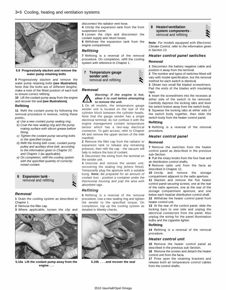
9 Progressively slacken and remove thewater pump retaining bolts (see illustration).Note that the bolts are of different lengths;make a note of the fitted position of each boltto ensure correct refitting.10 Lift the coolant pump away from the engineand recover the seal (see illustrations).
Refitting11 Refit the coolant pump by following theremoval procedure in reverse, noting thesepoints:.a) Use a new coolant pump sealing ring..b) Coat the new sealing ring and the pump
mating surface with silicon grease beforefitting.
c) Tighten the coolant pump securing boltsto the specified torque.
d) Refit the timing belt cover, coolant pumppulley and auxiliary drive belt, accordingto the information given in Chapter 2Cand Chapter 1 (as applicable).
e) On completion, refill the cooling systemwith the specified quantity of correctly-mixed coolant.
6 Expansion tank -removal and refitting 2
Removal1 Drain the cooling system as described inChapter 1.2 Remove the filler cap.3 Where applicable, loosen the clip and
disconnect the radiator vent hose.4 Unclip the expansion tank from the frontsuspension turret.5 Loosen the clips and disconnect thecoolant supply and return hoses.6 Withdraw the expansion tank from theengine compartment.
Refitting7 Refitting is a reversal of the removalprocedure. On completion, refill the coolingsystem with reference to Chapter 1 .
7 Temperature gauge sender unit -removal and refitting
2Removal
Warning: If the engine is hot,allow it to cool before attemptingto remove the unit.
1 On all models, the temperature gaugesender unit is located on the rear of thecylinder block between the cylinder heads.Note that the gauge sender has a singleelectrical terminal; do not confuse it with theengine management coolant temperaturesensor which has a two-way electricalconnector. To gain access, refer to Chapter4A and remove the upper section of the inletmanifold.2 Remove the filler cap from the radiator orexpansion tank to release any remainingpressure, then refit the cap - the vacuum willhelp to reduce the loss of coolant.3 Disconnect the wiring from the terminal onthe sender unit.4 Unscrew and remove the sender unit,recovering the sealing ring (where fitted).Temporarily plug the aperture with a suitablebung. Note: Be prepared for an amount ofcoolant loss - position a container under thethermostat housing and pad the area withabsorbent rags .
Refitting5 Refitting is a reversal of the removalprocedure. Use a new sealing ring and tightenthe sender to the specified torque. Oncompletion, top up the cooling system asdetailed in Weekly checks.
8 Heater/ventilation system components -removal and refitting
3Note: For models equipped with ElectronicClimate Control, refer to the information givenin Section 13.
Heater control panel switches
Removal1 Disconnect the battery negative cable andposition it away from the terminal.2 The number and types of switches fitted willvary with model specification, but the removalmethod for each switch is identical.3 Obtain two small flat bladed screwdrivers.Pad the ends of the blades with insulatingtape.4 Insert the screwdrivers into the recesses ateither side of the switch to be removed.Carefully depress the locking tabs and leverthe switch button away from the switch body.5 Squeeze the locking tabs at either side ofthe switch body together, then slide theswitch body from the heater control panel.
Refitting6 Refitting is a reversal of the removalprocedure.
Heater control panel
Removal7 Remove the switches from the heatercontrol panel as described in the previoussub-Section.8 Pull the rotary knobs from the four heat andair distribution control shafts.9 Remove radio unit from the facia asdescribed in Chapter 12.10 Unclip and remove the storagecompartment adjacent to the radio aperture.11 Slacken and remove the five heatercontrol panel securing screws; one at the rearof the radio aperture, one at the rear of thestorage compartment aperture, and onebelow each heat/air distribution control shaft.12 Withdraw the heater control panel fromheater control unit.13 At the rear of the control panel, slide thelocking bars to one side and unplug theelectrical connectors from the panel. Alsounplug the wiring for the panel illuminationbulbs and the cigarette lighter.
Refitting14 Refitting is a reversal of the removalprocedure.
Heater control unit15 Remove the heater control panel asdescribed in the previous sub-Section.16 Remove the screws and detach the heatercontrol unit from the facia.17 Prise open the retaining brackets andrelease both air temperature control cablesfrom the control shafts.
3•6 Cooling, heating and ventilation systems
5.9 Progressively slacken and remove thewater pump retaining bolts
5.10a Lift the coolant pump away from theengine . . .
5.10b . . . and recover the seal
3510 Vauxhall/Opel Omega
18 Unplug the wiring connector from the rearof the fan control switch.19 Disconnect the vacuum control hosemanifold from the rear of the control panel.20 Remove the control panel from thevehicle.
Refitting21 Refitting is a reversal of the removalprocedure.
Air distribution unitNote: On models with air conditioning, thisprocedure involves having the refrigerantcircuit discharged by a Vauxhall dealer or anair conditioning specialist.
Removal22 Drain the coolant as described in Chapter 1.23 Remove the facia as described in Chap-ter 11.24 On models with air conditioning, therefrigerant circuit must be now be dischargedby an air conditioning specialist or a Vauxhalldealer, to allow the air conditioning lines to bedisconnected from the engine compartmentbulkhead. Refer to the precautions given inSection 11 before proceeding.25 Unclip and remove the duct for the facelevel air vent on the drivers side of the vehicle.26 With reference to Chapter 10, unbolt andremove the steering column bracing strut,from the steering column and the floorpan.27 Undo the bolt and release the earth cablefrom the bulkhead.28 Unplug the wiring connector from theblower motor resistor pack, at the connector.29 Place a suitable container beneath thepoint where the heater matrix coolant pipesenter the air distribution unit.30 Unscrew the bolt to release the piperetaining plate, then disconnect the coolantpipes from the heater matrix, at the right handside of the air distribution unit. Allow theescaping coolant to drain into the container.Press the coolant pipes back towards theengine compartment, clear of the airdistribution unit.31 On models with air conditioning,disconnect the black vacuum hose from thecoolant cut-off valve.32 Unplug the wiring connector from therecirculation valve solenoid.33 On models without electronic climatecontrol, disconnect the yellow vacuum hosefrom the air distribution unit.34 Undo the securing screws and detach therear passenger compartment footwell ductsfrom the distribution unit.35 Disconnect the blue vacuum hose fromthe recirculation valve vacuum unit.36 On models with automatic transmission,release the cable ties and separate theselector cable from the recirculation valvesolenoid.37 Working in the engine compartment,slacken and withdraw the two distribution unitsecuring bolts, located near the upper edge ofthe bulkhead.
38 Working inside the car, unscrew andremove the last distribution unit securing bolt.39 Pull the unit up and away from the facia,the lift it over the facia wiring harness andremove it from the vehicle.
Refitting40 Refitting is a reversal of the removalprocedure, noting the following points:.a) Use new O-ring seals when reconnecting
the heater matrix coolant pipes.b) Use new O-ring seals when reconnecting
the air conditioning refrigerant pipes tothe bulkhead.
c) Observe the correct tightening torqueswhen reconnecting the steering columnbracing strut (see Chapter 10).
d) On model with air conditioning, have therefrigerant circuit evacuated andrecharged by an air conditioning specialistor a Vauxhall dealer.
e) Ensure that all vacuum and electricalconnections are securely re-made
f) On completion, refill the cooling systemas described in Chapter 1.
Heater matrix41 See Section 9.
Blower motor and fan42 See Section 10.
Heater control cable - driver’s side
Removal43 Release the facia from the bulkhead, withreference to Chapter 11. Pull it away from thebulkhead just far enough to gain access to therear of the air distribution unit.44 Prise open the retaining clip and thendisconnect the cable inner from the operatinglever on the air distributor unit.45 Remove the heater control panel asdescribed earlier in this Section.46 Prise open the retaining clip and thendisconnect the cable inner from the quadrantat the end of the control shaft.47 Remove the cable from the vehicle.
Refitting48 Refitting is a reversal of the removalprocedure. Set the operating lever on the airdistributor unit in the vertical position beforereconnecting the control cable inner.
Heater control cable -passenger side49 Proceed as described for the driver’s sidecontrol cable, in the previous sub-Section,noting that the air duct for the passengerfootwell vent must be removed to gain accessto the cable.
Recirculation air valve solenoid
Removal50 Disconnect the battery negative cable andposition it away from the terminal.
51 On right hand drive models, remove theglove compartment from the facia, asdescribed in Chapter 11, then unclip andremove the air duct for the passenger footwellvent.52 On left hand drive models, remove thelower trim panel from the drivers side of thefacia, then unclip and remove the air duct forthe drivers footwell vent.53 The solenoid is mounted on the left handside of the air distributor unit. Note theconnection order of each of the vacuumhoses, then disconnect them from thesolenoid valve ports.54 Unplug the wiring connector from thesolenoid valve.55 Slacken and withdraw the securing screwthen remove the solenoid valve from thevehicle.
Refitting56 Refitting is a reversal of the removalprocedure. Ensure that the valve sits squarelyin its guide slots, and that the vacuum hosesare correctly reconnected according to thenotes made during removal.
Recirculation air valve vacuumunit
Removal57 Remove the glove compartment from thefacia, as described in Chapter 11.58 Release the cable ties, then depress thelocking tabs and disengage the wiringharness support from the facia. Unclip andremove the air ducting.59 The recirculation air valve vacuum unit islocated on the left hand side of the blowermotor housing, and is distinguished by theblue vacuum hose leading to it.60 Disconnect the vacuum hose from theside of the vacuum unit.61 Lever the unit from its mounting boss.Disconnect the actuator arm from the lever atthe base of the vacuum unit, then remove thevacuum unit from the vehicle.
Refitting62 Refitting is a reversal of the removalprocedure.
Defroster valve vacuum unit63 Proceed as described for the recirculationvalve vacuum unit, in the previous sub-Section. The defroster valve vacuum unit islocated on the right hand side of the airdistributor unit and is distinguished by thebrown vacuum hose leading to it.
Footwell valve vacuum unit64 Proceed as described for the recirculationvalve vacuum unit, in the previous sub-Section. The footwell valve vacuum unit islocated on the right hand side of the airdistributor unit and is distinguished by thegreen vacuum hose leading to it.
Cooling, heating and ventilation systems 3•7
3
3510 Vauxhall/Opel Omega

Vacuum control circuit
General information65 The heating and ventilation system iscontrolled by a series of valves which directair through the required air ducts, accordingto the position of the control knobs on theheater control panel. The valves are actuatedby vacuum supplied engine inlet manifold.The following diagram is provided to show theorder of vacuum hose and vacuum unitconnection (see illustration).
9 Heater matrix -removal and refitting 4
Removal1 Disconnect the battery negative cable andposition it away from the terminal.2 Drain the coolant as described in Chapter 1.3 Refer to Chapter 11 and remove the facia.4 With reference to Chapter 10, unbolt thelower end of the steering column bracing strutand pivot it upwards away from the floorpan.5 Remove the securing screw and unclip theair duct for the drivers footwell vent from theside of the air distributor unit.6 Detach the drivers side control cable fromthe air distributor unit, as described in theprevious Section.7 Place a suitable container beneath the pointwhere the heater matrix coolant pipes enterthe air distribution unit.8 Unscrew the bolt to release the piperetaining plate, then disconnect the coolantpipes from the heater matrix, at the right handside of the air distribution unit, and recoverthe O-ring seals. Allow the escaping coolantto drain into the container. Press the coolantpipes back towards the engine compartment,clear of the air distribution unit.9 Slacken and remove the securing screwsthen withdraw the heater matrix from the sideof the air distribution unit, recover the rubberseal (see illustration). If a new heater matrixis to be fitted, extract the captive nut (for thecoolant pipe retaining plate) from the plasticcasing of the old matrix and transfer it to thenew one.
Refitting10 Refitting is a reversal of the removalprocedure, noting the following points:.a) Use new O-ring seals when reconnecting
the heater matrix coolant pipes.b) Observe the correct tightening torques
when reconnecting the steering columnbracing strut (see Chapter 10).
c) On completion, refill the cooling systemas described in Chapter 1.
10 Blower motor and series resistor -removal and refitting
3Blower motor
Removal1 Disconnect the battery negative cable andposition it away from the terminal.2 Remove the glove compartment from thefacia as described in Chapter 11.3 Release the cable ties, then depress thelocking tabs and disengage the wiringharness support from the facia. Unclip andremove the air ducting.
4 Disconnect the vacuum hose from the sideof the air recirculation valve vacuum unit thenremove the unit from its mounting bracket(see Section 8).5 Unplug the wiring harness leading to theblower motor series resistor.6 Slacken and remove the securing screws,then withdraw the blower motor and fanassembly from its housing (see illustrations).
Refitting7 Refitting is a reversal of the removalprocedure.
3•8 Cooling, heating and ventilation systems
10.6a Slacken and remove the securingscrews . . .
9.9 Heater matrix securing screw (A) andcoolant pipe retaining plate bolt (B)
3510 Vauxhall/Opel Omega
8.65 Heating/ventilation system vacuum control circuit
1 Vacuum reservoir2 Blue vacuum hose3 Vacuum unit, recirculating air valve4 Vacuum unit, defroster valve5 Brown vacuum hose6 Vacuum unit, footwell valve7 Green vacuum hose8 Connector, vacuum hoses
9 Heater controls10 Recirculating air switch11 Solenoid valve wiring, recirculating air valve12 Blue vacuum hose13 Solenoid valve, recirculating air valve14 Yellow vacuum hose15 Bulkhead16 Vacuum supply hose

Series resistor
Removal8 Proceed as described in paragraphs 1 to 3inclusive in the previous sub-Section.9 Unplug the wiring harness from the blowermotor series resistor at the connector (seeillustration).10 Depress the retaining tabs and withdrawthe resistor from the fan/motor housing (seeillustration).
Refitting11 Refitting is a reversal of removal.
11 Air conditioning system -description and precautions
General information1 An air conditioning system is available oncertain models. When activated, the airconditioning system allows air entering thepassenger to be cooled giving greater controlover the temperature inside the car andleading to increased comfort. The cooled air isalso dehumidified, enabling faster windscreendemisting.2 The cooling side of the system works in thesame way as a domestic refrigerator.Refrigerant gas, contained in a sealed networkof alloy pipes, is drawn into a belt-drivencompressor, and is forced through a condensermounted on the front of the radiator. Onentering the condenser, the refrigerant changesstate from gas to liquid and releases heat,which is absorbed by the air flowing into theengine compartment through the condenser.The liquid refrigerant passes through anexpansion valve to an evaporator, where itchanges from liquid under high pressure to gasunder low pressure. This change in state isaccompanied by a drop in temperature, whichcools the evaporator. Air passing through theevaporator is cooled before flowing into the airdistribution unit. The refrigerant then returns tothe compressor, and the cycle begins again.3 Cool air passes to the air distribution unit,where it is mixed with hot air blown throughthe heater matrix, to achieve the desired
temperature in the passenger compartment.On models with Electronic Climate control,the cabin temperature is regulatedautomatically by a system of air valvescontrolled by servo motors.4 The heating side of the system works in thesame way as on models without airconditioning (see Section 8).5 The operation of the system is controlled byan electronic control unit, which controls theelectric cooling fan, the compressor, and thefacia-mounted warning light. Any problemswith the system should be referred to aVauxhall dealer.
Precautions6 When an air conditioning system is fitted, itis necessary to observe special precautionswhenever dealing with any part of the system,or its associated components. If for anyreason the system must be disconnected, youmust entrust this task to a Vauxhall dealer oran air conditioning specialist. Similarly, thesystem can only be evacuated and rechargedby a dealer or air conditioning specialist.
Warning: The air conditioningsystem contains a pressurisedliquid refrigerant. If the system is
discharged in an uncontrolled mannerwithout the aid of specialist equipment, therefrigerant will boil as soon as it is exposedto the atmosphere, causing severefrostbite if it comes into contact withunprotected skin. In addition, certainrefrigerants, in the presence of a nakedflame (including a lit cigarette), will burn to
form a highly poisonous gas. It is thereforeextremely dangerous to disconnect anypart of the air conditioning system withoutspecialised knowledge and equipment. 7 Uncontrolled discharging of the refrigerantcan also be damaging to the environment, ascertain refrigerants contain CFCs.8 Do not operate the air conditioning systemif it is known to be short of refrigerant, as thiswill damage the compressor.
12 Air conditioning system components -removal and refitting
3Warning: Do not attempt todischarge the refrigerant circuityourself - refer to the precautions
given in Section 11. Have the airconditioning system discharged by aqualified engineer.On completion, have the refrigerantengineer fit new O-rings to the lineconnections and evacuate and re-chargethe system.
Auxiliary coolant pump
Removal1 Drain the coolant as described in Chapter 1.2 Remove the battery as described inChapter 5A.3 Remove the screws and lift the upper coverfrom the top of the radiator.4 Unplug the wiring from the auxiliary coolantpump at the connector.5 Release the securing clips and detach theauxiliary coolant pump from the radiator.
Refitting6 Refitting is a reversal of removal. Oncompletion, top up the cooling system asdescribed in Weekly checks.
Compressor
Removal -Models with 4-cylinder engines7 Have the air conditioning systemdischarged by a qualified engineer.8 Remove the battery as described in Chap-ter 5A.9 Remove the auxiliary drivebelt as describedin Chapter 1.10 Unbolt the refrigerant lines from thecompressor.11 Unplug the wiring connector from theclutch unit at the underside of the compressor.12 Unscrew the three securing bolts from thefront of the compressor.13 Unscrew the three securing bolts from therear of the compressor, then remove thecompressor from its mounting bracket.
Refitting -Models with 4-cylinder engines14 Refitting is a reversal of the removalprocedure; ensure that all fixings are tightenedto the specified torque, where given. On
Cooling, heating and ventilation systems 3•9
3
10.6b . . . then withdraw the blower motorand fan assembly from its housing
10.9 Unplug the wiring harness from theblower motor series resistor at the
connector
10.10 Withdraw the resistor from thefan/motor housing
3510 Vauxhall/Opel Omega

completion, have the refrigerant engineer fitnew O-rings to the line connections andevacuate and re-charge the refrigerant circuit.
Removal -Models with 6-cylinder engines15 Have the air conditioning systemdischarged by a qualified engineer.16 Remove the battery as described inChapter 5A.17 Remove the auxiliary drivebelt asdescribed in Chapter 1.18 Uncouple the low pressure refrigerantpipe at the service union. Work along thelength of the pipe that remains connected tothe compressor and release it from anyretaining brackets.19 Uncouple the high pressure refrigerantpipe at the pulsation damper unit. Work alongthe length of the pipe that remains connectedto the compressor and release it from anyretaining brackets.20 Unplug the wiring connector from theclutch unit at the underside of the compressor.21 Unscrew the three securing bolts from thefront of the compressor.22 Unscrew the two securing bolts from therear of the compressor.23 Rotate the compressor so that the fluidfiller bolt faces towards the engine sump, thenremove the compressor from its mountingbracket.
Refitting -Models with 6-cylinder engines24 Refitting is a reversal of the removalprocedure; ensure that all fixings aretightened to the specified torque, wheregiven. On completion, have the refrigerantengineer fill the compressor with lubricant, fitnew O-rings to the line connections and thenevacuate and re-charge the refrigerant circuit.
Expansion valve25 Have the air conditioning systemdischarged by a qualified engineer.26 Disconnect the battery negative cable andposition it away from the terminal.27 Refer to Chapter 11 and remove the glovecompartment.28 Refer to Section 10 and remove theblower motor.29 Disconnect the refrigerant lines at theengine compartment bulkhead.30 Unbolt the solenoid valves from the evapor-ator housing and position them to one side.31 Remove the six securing screws and liftthe evaporator cover from the air distributorunit.32 Unbolt the retainer plate, disconnect therefrigerant lines, then unbolt the expansionvalve from the evaporator.
Refitting33 Refitting is a reversal of removal. Ensurethat all fixings are tightened to the specifiedtorque, where given. On completion, have therefrigerant engineer fit new O-rings to the lineconnections and then evacuate and re-chargethe refrigerant circuit.
Evaporator
Removal34 Remove the expansion valve as describedin previous sub-Section, then withdraw theevaporator from the air distributor unit.
Refitting35 Refitting is a reversal of removal.
Condenser
Removal -Models with 4 cylinder engines36 Have the air conditioning systemdischarged by a qualified engineer.37 Disconnect the battery negative cable andposition it away from the terminal.38 Remove the radiator as described inSection 2.39 Slacken and separate the unions, then dis-connect the refrigerant lines from thecondenser and tape over or plug them.40 Carefully lift the condenser from its rubberguide and withdraw it from the vehicle.
Refitting41 Refitting is a reversal of removal. Have arefrigerant engineer fit new O-rings to the lineconnections and then evacuate and re-chargethe refrigerant circuit. On completion, refill thecooling system with reference to Chapter 1.
Removal -Models with 6 cylinder engines42 Have the air conditioning systemdischarged by a qualified engineer.43 Disconnect the battery negative cable andposition it away from the terminal.44 Remove the radiator as described inSection 2.45 Slacken and separate the unions, then dis-connect the refrigerant lines from thecondenser and tape over or plug them.46 Carefully lift the condenser from its rubberguide and tilt it backwards towards theengine.47 Slacken and separate the unions, then dis-connect the refrigerant lines from the receiver/dryer unit and tape over or plug them.48 Undo the screws and detach thereceiver/dryer unit mounting bracket from thecondenser.49 Carefully lift the condenser from its rubberguide and withdraw it from the vehicle,together with the receiver/dryer unit.
Refitting -Models with 6 cylinder engines50 Refitting is a reversal of removal. Have arefrigerant engineer fit new O-rings to the lineconnections and then evacuate and re-chargethe refrigerant circuit. On completion, refill thecooling system with reference to Chapter 1.
Receiver/dryer
Removal51 Have the air conditioning systemdischarged by a qualified engineer.
52 Disconnect the battery negative cable andposition it away from the terminal.53 Refer to Chapter 11 and remove theradiator grille.54 Detach the filler neck from the top of thewindscreen washer fluid reservoir. On modelswith 6-cylinder engines, unbolt and removethe crossmember from the front of the enginecompartment.55 Punch out the pre-stressed holes in thecooling fan casing to gain access to therefrigerant line unions, at the top of thereceiver/dryer unit.56 Slacken and separate the unions, then dis-connect the refrigerant lines from the receiver/dryer unit and tape over or plug them.57 Undo the screws and detach thereceiver/dryer unit mounting bracket from thefront of the vehicle. Remove the unit from theengine compartment, together with itsmounting bracket.
Refitting58 Refitting is a reversal of removal. Oncompletion, have a refrigerant engineer fit newO-rings to the line connections and thenevacuate and re-charge the refrigerant circuit.
Tri-switch
Removal59 The tri-switch is located beneathreceiver/dryer unit at the front left hand cornerof the engine compartment. Have the airconditioning system discharged by a qualifiedengineer.60 Disconnect the battery negative cable andposition it away from the terminal.61 Unplug the wiring from the tri-switch atthe multi-way connector.62 Counterhold the refrigerant line union andunscrew the tri-switch.
Refitting63 Refitting is a reversal of removal. Oncompletion, have a refrigerant engineer fit newO-rings to the line connections and thenevacuate and re-charge the refrigerant circuit.
Cooling fan thermo-switches
Main radiator fan64 The main radiator fan thermo-switch islocated at the lower edge of the radiator.65 Drain the cooling system as described inChapter 1.66 Disconnect the battery negative cable andposition it away from the terminal.67 Unplug the wiring from the switch at themulti-way connector.68 Unscrew the switch from the radiator.69 Refitting is a reversal of removal, but use anew switch sealing ring. On completion refillthe cooling system as described in Chapter 1.
Auxiliary fan70 The auxiliary radiator fan thermo-switch islocated at the left hand side of the radiator.71 Drain the cooling system as described inChapter 1.
3•10 Cooling, heating and ventilation systems
3510 Vauxhall/Opel Omega

72 Disconnect the battery negative cable andposition it away from the terminal.73 Unplug the wiring from the switch at themulti-way connector.74 Unscrew the switch from the radiator.75 Refitting is a reversal of removal, but use anew switch sealing ring. On completion refillthe cooling system as described in Chapter 1.
13 Electronic Climate Control(ECC) components - removal and refitting
3ECC control panel and switchesRemoval1 Disconnect the battery negative cable andposition it away from the terminal.2 Remove ashtray from the facia asdescribed in Chapter 11.3 Remove radio unit from the facia asdescribed in Chapter 12, then remove theradio mounting frame.4 Slacken and remove the securing screwsfrom the lower edge of the control panel (seeillustration).5 Reach through the radio aperture and pulldown on the aluminium locking bar at the rearof the upper edge of the control panel (seeillustrations).6 Remove the panel from the facia. At therear of the control panel, slide the locking barsto one side and unplug the electricalconnectors from the panel. Also unplug thewiring for the control panel and ashtrayillumination bulbs (see illustrations).7 If required, the ECC switch controls can bedetached from the control panel by removingthe relevant securing screws.
Refitting8 Refitting is a reversal of removal, noting thefollowing points:.a) Ensure that locking bar at the rear upper
edge of the control panel is correctlyengaged.
b) On completion, synchronise the air valveservo motors as follows: Switch theignition to the On position, then depressand hold the Auto and Off keys on theECC control panel for more than 5seconds.
Defroster air valve servo motorRemoval9 Disconnect the battery negative cable andposition it away from the terminal. Removethe lower trim panel from the drivers side ofthe facia, then unclip and remove the air ductfor the drivers footwell vent.10 The servo motor is mounted on the righthand side of the air distributor unit (seeillustration).11 Unplug the wiring harness from the servomotor at the multiway connector.12 Undo the securing screws and withdrawthe servo motor from the air distributor unit.13 Disengage the motor spindle arm from theactuator rod.
Refitting14 Refitting is a reversal of removal. Oncompletion, synchronise the air valve servo
motors as follows: turn the ignition switch tothe On position, then depress and hold theAuto and Off keys on the ECC control panelfor more than 5 seconds.
Footwell air valve servo motor
Removal15 Refer to the previous sub-Section andremove the defroster air valve servo motor.16 The servo motor is mounted on the righthand side of the air distributor unit, in front ofthe defroster air valve servo motor (seeillustration).17 Unplug the wiring harness from the servomotor at the multiway connector.18 Undo the securing screws and withdrawthe servo motor from the air distributor unit.
Cooling, heating and ventilation systems 3•11
3
13.4 Slacken and remove the securingscrews from the lower edge of the ECC
panel13.5a Reach through the radio aperture . . . 13.5b . . . and pull down on the aluminium
locking bar at the rear of the upper edge ofthe control panel (shown with panel
removed for clarity)
13.6b . . . and remove the ECC panel fromthe facia
13.6a Unplug the wiring harnessconnectors . . .
13.10 Location of the ECC defroster airvalve servo
13.16 Location of the ECC footwell airvalve servo
3510 Vauxhall/Opel Omega

Refitting19 Turn the servo motor spindle gear fullyclockwise to the end of its stop. Similarly, turnthe spindle gear air distributor housing fullyclockwise to the end of its stop.20 Refit the motor and tighten its securingscrews. Reconnect the wiring harness.21 Refit the defroster air valve servo motor asdescribed in the previous sub-Section. Refitall components removed for access.22 On completion, synchronise the air valveservo motors as follows: turn the ignitionswitch to the On position, then depress andhold the Auto and Off keys on the ECC controlpanel for more than 5 seconds.
Centre vent servo motor
Removal23 Disconnect the battery negative cable andposition it away from the terminal.24 Remove the lower trim panel from thedrivers side of the facia, then unclip and removethe air duct for the drivers footwell vent.25 The servo motor is mounted on the righthand side of the air distributor unit, above thedefroster air valve servo motor.26 Unplug the wiring harness from the servomotor at the multiway connector.27 Undo the securing screws and withdrawthe servo motor from the air distributor unit.28 Disengage the motor spindle arm from theactuator rod.
Refitting29 Refitting is a reversal of removal. Oncompletion, synchronise the air valve servomotors as follows: turn the ignition switch tothe On position, then depress and hold the
Auto and Off keys on the ECC control panelfor more than 5 seconds.
Right hand vent servo motor
Removal30 Disconnect the battery negative cable andposition it away from the terminal.31 Remove the lower trim panel from thedrivers side of the facia, then unclip and removethe air duct for the drivers footwell vent.32 Unclip the cover panel to expose theservo motor (see illustration).33 Unplug the wiring harness from the servomotor at the multiway connector.34 Undo the securing screws and withdrawthe servo motor from the air distributor unit.35 Disengage the motor spindle arm from theactuator rod and actuator lever.
Refitting36 Refitting is a reversal of removal. Oncompletion, synchronise the air valve servomotors as follows: turn the ignition switch tothe On position, then depress and hold theAuto and Off keys on the ECC control panelfor more than 5 seconds.
Left hand vent servo motor
Removal37 Disconnect the battery negative cable andposition it away from the terminal. Removethe glove compartment from the facia, asdescribed in Chapter 11.38 Release the cable ties, then depress thelocking tabs and disengage the wiringharness support from the facia. Unclip andremove the air ducting.39 Unclip the cover panel to expose theservo motor.40 Unplug the wiring harness from the servomotor at the multiway connector.41 Undo the securing screws and withdrawthe servo motor from the air distributor unit.42 Disengage the motor spindle arm from theactuator rod and actuator lever.
Refitting43 Refitting is a reversal of removal. Oncompletion, synchronise the air valve servomotors as follows: turn the ignition switch tothe On position, then depress and hold theAuto and Off keys on the ECC control panelfor more than 5 seconds.
Right hand vent temperature sensorRemoval44 Remove the footwell air valve servo motoras described earlier in this Section.45 Unplug the wiring from the sensor at theconnector.46 Carefully prise the sensor body away fromits mounting clip and withdraw the probe fromthe air ducting (see illustration).
Refitting47 Refitting is a reversal of removal. Oncompletion, refit the footwell air valve servomotor, then synchronise the air valve servomotors as follows: turn the ignition switch tothe On position, then depress and hold theAuto and Off keys on the ECC control panelfor more than 5 seconds.
Left hand vent temperature sensorRemoval48 Disconnect the battery negative cable andposition it away from the terminal. Removethe glove compartment from the facia, asdescribed in Chapter 11.49 Release the cable ties, then depress thelocking tabs and disengage the wiringharness support from the facia. Unclip andremove the air ducting.50 Note the direction that the wiringconnector is facing, then pull the sensor torelease it from the air distributor unit, thenrotate it clockwise through half a turn andunplug the wiring connector.51 Tilt the sensor to the left and withdraw itfrom its aperture.
Refitting52 Refitting is a reversal of removal. Ensurethat when the sensor is refitted, the wiringconnector faces the right hand side of thevehicle, as noted during removal.
Blower motor regulatorRemoval53 Disconnect the battery negative cable andposition it away from the terminal. Removethe glove compartment from the facia, asdescribed in Chapter 11.54 Depress the retaining lugs and withdrawthe regulator from the fan housing. Unplug thewiring from the regulator at the connector.
Refitting55 Refitting is a reversal of removal.
Sun sensorRemoval56 Carefully lever the sensor from the faciausing blunt soft bladed instrument (seeillustration).57 Secure a cable tie around the wiringharness to prevent it from falling back into thefacia, then disconnect it from the sensor.
Refitting58 Refitting is a reversal of removal.
3•12 Cooling, heating and ventilation systems
13.32 Unclip the cover panel to expose theright hand vent servo motor
13.46 Location of the ECC right hand venttemperature sensor
13.56 Carefully lever the sun sensor fromthe upper surface of the facia
3510 Vauxhall/Opel Omega

3510 Vauxhall/Opel Omega
4A•1
4A
Chapter 4 Part A:Fuel and exhaust systems
System type2.0 litre SOHC engine . . . . . . . . . . . . . . . . . . . . . . . . . . . . . . . . . . . . . . . Bosch Motronic M1.5.4*2.0 litre DOHC engine . . . . . . . . . . . . . . . . . . . . . . . . . . . . . . . . . . . . . . . Simtec 56.1 or 56.5*2.5 and 3.0 litre engine . . . . . . . . . . . . . . . . . . . . . . . . . . . . . . . . . . . . . . Bosch Motronic M2.8.1 or M2.8.3**See Section 6 for further information
Fuel system dataFuel pump type . . . . . . . . . . . . . . . . . . . . . . . . . . . . . . . . . . . . . . . . . . . . Electric, immersed in tankFuel pump regulated pressure (approximate) . . . . . . . . . . . . . . . . . . . . . 3.0 barSpecified idle speed . . . . . . . . . . . . . . . . . . . . . . . . . . . . . . . . . . . . . . . . Not adjustable - controlled by ECUIdle mixture CO content . . . . . . . . . . . . . . . . . . . . . . . . . . . . . . . . . . . . . Not adjustable - controlled by ECU
Recommended fuelMinimum octane rating . . . . . . . . . . . . . . . . . . . . . . . . . . . . . . . . . . . . . . 95 RON* unleaded (UK unleaded premium).
Leaded fuel must not be used*91 RON unleaded fuel can be used but a slight power loss maybe noticeable.
Accelerator cable - removal and refitting . . . . . . . . . . . . . . . . . . . . . 3Accelerator pedal - removal and refitting . . . . . . . . . . . . . . . . . . . . . 4Air cleaner assembly and intake ducts - removal and refitting . . . . . 2Air cleaner filter element renewal . . . . . . . . . . . . . . . . . .See Chapter 1Exhaust manifold - removal and refitting . . . . . . . . . . . . . . . . . . . . . . 16Exhaust system - general information, removal and refitting . . . . . . 18Exhaust system check . . . . . . . . . . . . . . . . . . . . . . . . . . .See Chapter 1Fuel filter renewal . . . . . . . . . . . . . . . . . . . . . . . . . . . . . . .See Chapter 1Fuel gauge sender unit - removal and refitting . . . . . . . . . . . . . . . . . 9Fuel injection system - depressurisation . . . . . . . . . . . . . . . . . . . . . . 7Fuel injection system - testing and adjustment . . . . . . . . . . . . . . . . . 12Fuel injection system components (2.0 litre engine) - removal and
refitting . . . . . . . . . . . . . . . . . . . . . . . . . . . . . . . . . . . . . . . . . . . . . . 13
Fuel injection system components (2.5 and 3.0 litre engines) - removaland refitting . . . . . . . . . . . . . . . . . . . . . . . . . . . . . . . . . . . . . . . . . . 14
Fuel injection systems - general information . . . . . . . . . . . . . . . . . . . 6Fuel pump - removal and refitting . . . . . . . . . . . . . . . . . . . . . . . . . . . 8Fuel tank - removal and refitting . . . . . . . . . . . . . . . . . . . . . . . . . . . . 10General information and precautions . . . . . . . . . . . . . . . . . . . . . . . . 1Inlet manifold - removal and refitting . . . . . . . . . . . . . . . . . . . . . . . . . 15Multi-ram air intake system - information and component removal
and refitting . . . . . . . . . . . . . . . . . . . . . . . . . . . . . . . . . . . . . . . . . . 17Throttle housing - removal and refitting . . . . . . . . . . . . . . . . . . . . . . 11Unleaded petrol - general information and usage . . . . . . . . . . . . . . . 5
Specifications
Contents
Easy, suitable fornovice with littleexperience
Fairly easy, suitablefor beginner withsome experience
Fairly difficult,suitable for competentDIY mechanic
Difficult, suitable forexperienced DIYmechanic
Very difficult,suitable for expert DIYor professional
Degrees of difficulty
54321

Torque wrench settings Nm Ibf ftAuxiliary drivebelt tensioner mounting bolts - 2.5 and 3.0 litre engines . 35 26Braking system vacuum hose union nut . . . . . . . . . . . . . . . . . . . . . . . . 20 15Camshaft sensor bolt:
2.0 litre DOHC engine . . . . . . . . . . . . . . . . . . . . . . . . . . . . . . . . . . . . . 6 42.5 and 3.0 litre engines . . . . . . . . . . . . . . . . . . . . . . . . . . . . . . . . . . . 8 6
Crankshaft sensor bolt . . . . . . . . . . . . . . . . . . . . . . . . . . . . . . . . . . . . . . 8 6EGR pipe union nuts - 2.5 and 3.0 litre engine . . . . . . . . . . . . . . . . . . . . 25 18Exhaust manifold heatshield bolts . . . . . . . . . . . . . . . . . . . . . . . . . . . . . 8 6Exhaust manifold nuts:
2.0 litre engine . . . . . . . . . . . . . . . . . . . . . . . . . . . . . . . . . . . . . . . . . . 22 162.5 and 3.0 litre engine . . . . . . . . . . . . . . . . . . . . . . . . . . . . . . . . . . . . 20 15
Exhaust system fasteners:Front pipe to manifold bolts:
2.0 litre engine . . . . . . . . . . . . . . . . . . . . . . . . . . . . . . . . . . . . . . . . . 25 182.5 and 3.0 litre engine . . . . . . . . . . . . . . . . . . . . . . . . . . . . . . . . . . 30 22
Front pipe to mounting bracket bolt . . . . . . . . . . . . . . . . . . . . . . . . . . 20 15Front pipe to intermediate pipe bolts . . . . . . . . . . . . . . . . . . . . . . . . . 18 13Intermediate pipe to tailpipe clamp . . . . . . . . . . . . . . . . . . . . . . . . . . 17 13
Fuel hose union nuts/bolts . . . . . . . . . . . . . . . . . . . . . . . . . . . . . . . . . . . 15 11Fuel pressure regulator clamp screw . . . . . . . . . . . . . . . . . . . . . . . . . . .Fuel rail bolts . . . . . . . . . . . . . . . . . . . . . . . . . . . . . . . . . . . . . . . . . . . . . 8 6Fuel tank retaining strap bolts . . . . . . . . . . . . . . . . . . . . . . . . . . . . . . . . 30 22Inlet manifold nuts and bolts:
2.0 litre engine . . . . . . . . . . . . . . . . . . . . . . . . . . . . . . . . . . . . . . . . . . 22 162.5 and 3.0 litre engines:
Flange to cylinder head bolts . . . . . . . . . . . . . . . . . . . . . . . . . . . . . 20 15Lower section:
Retaining bolts . . . . . . . . . . . . . . . . . . . . . . . . . . . . . . . . . . . . . . 20 15Fuel pipe adaptor mounting bolts . . . . . . . . . . . . . . . . . . . . . . . . 8 6
Upper section retaining bolts . . . . . . . . . . . . . . . . . . . . . . . . . . . . . 8 6Knock sensor bolt . . . . . . . . . . . . . . . . . . . . . . . . . . . . . . . . . . . . . . . . . . 20 15Oil cooler pipe union nuts and bolts - 2.5 and 3.0 litre engines . . . . . . . 30 22Spark plug heatshields - 2.0 litre SOHC engine . . . . . . . . . . . . . . . . . . . 25 18Throttle housing nuts/bolts:
2.0 litre engine . . . . . . . . . . . . . . . . . . . . . . . . . . . . . . . . . . . . . . . . . . 9 72.5 and 3.0 litre engine . . . . . . . . . . . . . . . . . . . . . . . . . . . . . . . . . . . . 8 6
1 General information andprecautions
1 The fuel system consists of a fuel tank(which is mounted under the rear of the car,with an electric fuel pump immersed in it), afuel filter and the fuel feed and return lines.The fuel pump supplies fuel to the fuel rail,which acts as a reservoir for the fuel injectors(one for each cylinder) which inject fuel intothe inlet tracts. In addition, there is anElectronic Control Unit (ECU) and varioussensors, electrical components and relatedwiring.2 Refer to Section 6 for further information onthe operation of each fuel injection system,and to Section 18 for information on theexhaust system.
Warning: Many of the proceduresin this Chapter require theremoval of fuel lines and
connections, which may result in some fuelspillage. Before carrying out any operation
on the fuel system, refer to the precautionsgiven in Safety first! at the beginning ofthis manual, and follow them implicitly.Petrol is a highly-dangerous and volatileliquid, and the precautions necessarywhen handling it cannot be overstressed.Note: Residual pressure will remain in the fuellines long after the vehicle was last used.Before disconnecting any fuel line, firstdepressurise the fuel system as described inSection 7.
2 Air cleaner assembly and intake ducts - removal and refitting 2
RemovalNote: On 2.5 and 3.0 litre engines, refer toSection 17 for information on the multi-ram airintake system.1 To remove the air cleaner housing slackenthe retaining clip and disconnect the ductfrom the outlet then unclip the housing from
its mounting rubbers. Free the housing fromthe intake duct and remove it from the enginecompartment.2 The various ducts can be disconnected andremoved once the retaining clips have beenslackened. In some cases it will be necessaryto disconnect breather hoses and wiringconnectors to allow the duct to be removed;some duct sections are also bolted to asupport bracket.
Refitting3 Refitting is the reverse of removal, notingthe following.a) Examine the housing mounting rubbers
for signs of damage or deterioration andrenew if necessary.
b) On refitting, remove the mounting rubbersfrom the body and fit them to the housingpins. Ease installation by lubricating themounting rubbers with a spray-basedsilicone lubricant.
c) Ensure all ducts are securely joined andretained by the necessary clips andscrews.
4A•2 Fuel and exhaust systems
3510 Vauxhall/Opel Omega

3 Accelerator cable - removal and refitting 3
Removal1 Working in the engine compartment, unclipthe inner cable retaining clip then slide the clipout of the end fitting and release the cablefrom the throttle cam (see illustration).2 Free the accelerator outer cable from itsmounting bracket, taking care not to lose theadjusting clip (see illustration). Work backalong the length of the cable, free it from anyretaining clips or ties, noting its correctrouting. On models with automatictransmission it will be necessary todisconnect the wiring from the kickdownswitch which is built into the cable.3 To improve access, remove the windscreenwiper arms and the water deflector panel fromthe base of the windscreen (see Chapter 12,Sections 15 and 16).4 From inside the vehicle, release theretaining clips (rotate them through 90º) thenremove the undercover panel from the drivers’side of the facia. Remove the fastener (priseout the centre pin then pull out the fastenerouter section) then unclip and remove theheater/ventilation duct to improve access tothe accelerator pedal (see illustrations).5 Reaching up behind the facia, unclip theaccelerator inner cable from the top of theaccelerator pedal (see illustration).
6 Return to the engine compartment then freethe cable sealing grommet from the bulkheadand remove the cable and grommet from thevehicle.7 Examine the cable for signs of wear ordamage and renew if necessary.
Refitting8 Feed the cable into position from theengine compartment and seat the outer cablegrommet in the bulkhead.9 From inside the vehicle, clip the inner cableend fitting into position in the pedal end andcheck to make sure the grommet is correctlylocated in the bulkhead. Check that the cableis securely retained, then refit theheater/ventilation duct and undercover to thefacia.10 From within the engine compartment,ensure the outer cable is correctly seated inthe bulkhead, then work along the cable,securing it in position with the retaining clipsand ties, and ensuring that the cable iscorrectly routed. On models with automatictransmission, reconnect the kickdown switchwiring connector making sure the wiring iscorrectly routed.11 Refit the water deflector panel and installboth wiper arms (see Chapter 12).12 Connect the inner cable to the throttlecam and secure it in position with theretaining clip. Clip the outer cable into itsmounting bracket and adjust the cable asdescribed below.
Adjustment13 Working in the engine compartment, slideoff the adjustment clip from accelerator outercable.14 With the clip removed, ensure that thethrottle cam is fully against its stop. Gentlypull the cable out of its grommet until all freeplay is removed from the inner cable.15 With the cable held in this position, refitthe spring clip to the last exposed outer cablegroove in front of the rubber grommet. Whenthe clip is refitted and the outer cable isreleased, there should be only a small amountof free play in the inner cable.16 Have an assistant depress the acceleratorpedal, and check that the throttle cam opensfully and returns smoothly to its stop.
4 Accelerator pedal - removal and refitting 3
Removal1 From inside the vehicle, release the retainingclips (rotate them through 90º) then remove theundercover panel from the drivers’ side of thefacia. Remove the fastener (prise out the centrepin then pull out the fastener outer section) thenunclip and remove the heater/ventilation duct toimprove access to the accelerator pedal (seeillustrations 3.4a to 3.4c).
Fuel and exhaust systems 4A•3
4A
3.4a Release the retaining clips andremove the undercover panel from the
driver’s side of the facia
3.1 Remove the retaining clip and detachthe inner cable from the throttle cam . . .
3.2 . . . then free the outer cable from themounting bracket
3.4b Prise out the centre pin then removethe fastener outer section . . .
3.4c . . . and unclip the heater/ventilationduct
3.5 Unhook the accelerator cable(arrowed) from the upper end of the pedal
3510 Vauxhall/Opel Omega

2 Reaching up behind the facia, unclip theaccelerator inner cable end fitting from the topof the accelerator pedal (see illustration 3.5).3 Unscrew the retaining nuts and remove thepedal assembly from the bulkhead (seeillustration).4 Inspect the pedal assembly for signs ofwear, paying particular attention to the pedalbushes, and renew as necessary. Todismantle the assembly, unhook the returnspring then slide off the retaining clip andseparate the pedal, mounting bracket, returnspring and pivot bushes.
Refitting5 If the assembly has been dismantled, applya smear of multi-purpose grease to the pedalpivot shaft and bushes. Fit the bushes andreturn spring to the mounting bracket andinsert the pedal, making sure it passesthrough the return spring bore. Secure thepedal in position with the retaining clip andhook the return spring back behind the pedal.6 Refit the pedal assembly and securelytighten its retaining nuts.7 Clip the accelerator cable end fitting intothe pedal then refit the heater/ventilation ductand undercover to the facia.8 On completion, adjust the accelerator cableas described in Section 3.
5 Unleaded petrol - general information and usage
Note: The information given in this Chapter iscorrect at the time of writing. If updatedinformation is thought to be required, checkwith a Vauxhall dealer. If travelling abroad,consult one of the motoring organisations (or asimilar authority) for advice on the fuelavailable.1 The fuel recommended by Vauxhall is givenin the Specifications Section of this Chapter,followed by the equivalent petrol currently onsale in the UK.2 All petrol models are designed to run onfuel with a minimum octane rating of 95(RON). Lower octane fuel, down to minimumof rating 91 (RON), can be safely used since
the engine management system automaticallyadjusts the ignition timing to suit (using theinformation supplied by the knock sensor).However, a slight power loss is likely if fuelwith a octane rating of less than 95 (RON) isused. Vauxhall state that if 91 octane fuel is tobe used, as a precautionary measure, it iswise to avoid placing the engine under severeloads for any length of time (eg. towing or fullthrottle driving).3 All UK models have a catalytic converter,and so must be run on unleaded fuel only.Under no circumstances should leaded fuel(UK 4-star) be used, as this may damage theconverter.4 Super unleaded petrol (98 octane) can alsobe used in all models if wished, though thereis no advantage in doing so.
6 Fuel injection systems -general information
2.0 litre SOHC engine models -Bosch Motronic M1.5.4 system1 All 2.0 litre SOHC engine models areequipped with a Bosch Motronic enginemanagement (fuel injection/ignition) system(see illustration). On UK models the systemincorporates a closed-loop catalyticconverter, an evaporative emission controlsystem and an exhaust gas recirculation(EGR) system and complies with the latestemission control standards. The fuel injectionside of the system operates as follows; referto Chapter 5B for information on the ignitionsystem.2 The fuel pump, immersed in the fuel tank,pumps fuel from the fuel tank to the fuel rail,via a filter mounted underneath the rear of thevehicle. Fuel supply pressure is controlled bythe pressure regulator which allows excessfuel to be returned to the tank.3 The electrical control system consists of theECU, along with the following sensors.a) Throttle potentiometer - informs the ECU
of the throttle position, and the rate ofthrottle opening or closing.
b) Coolant temperature sensor - informs theECU of engine temperature.
c) Airflow meter - informs the ECU of theamount of air entering the inlet manifold.
d) Intake air temperature sensor - informsthe ECU of the temperature of the airentering the manifold.
e) Crankshaft sensor - informs the ECU ofengine speed and crankshaft position.
f) Knock sensor - informs the ECU whenpre-ignition (pinking) is occurring.g) Oxygen sensor (UK models) -informs the ECU of the oxygen content ofthe exhaust gases (explained in greaterdetail in Part B of this Chapter).
h) ABS control unit - informs the ECU of thevehicle speed.
i) Air conditioning system compressorswitch (where fitted) - informs ECU whenthe air conditioning system is switchedon.
4 All the above information is analysed by theECU and, based on this, the ECU determinesthe appropriate ignition and fuellingrequirements for the engine. The ECUcontrols the fuel injector by varying its pulsewidth - the length of time the injector is heldopen - to provide a richer or weaker mixture,as appropriate. The mixture is constantlyvaried by the ECU, to provide the best settingfor cranking, starting (with either a hot or coldengine), warm-up, idle, cruising, andacceleration.5 The ECU also has full control over theengine idle speed, via the idle speed adjusterwhich is fitted to the throttle housing. Theadjuster controls the opening of an airpassage which bypasses the throttle valve.When the throttle valve is closed (acceleratorpedal released), the ECU uses the adjuster tovary the amount of air entering the engine andso controls the idle speed.6 The ECU also controls the exhaust andevaporative emission control systems, whichare described in detail in Part B of thisChapter.7 If there is an abnormality in any of thereadings obtained from any sensor, the ECUenters its back-up mode. In this event, theECU ignores the abnormal sensor signal, andassumes a pre-programmed value which willallow the engine to continue running (albeit atreduced efficiency). If the ECU enters thisback-up mode, the warning light on theinstrument panel will come on, and therelevant fault code will be stored in the ECUmemory.8 If the warning light comes on, the vehicleshould be taken to a Vauxhall dealer at theearliest opportunity. A complete test of theengine management system can then becarried out, using a special electronicdiagnostic test unit which is simply pluggedinto the system’s diagnostic connector. Theconnector is located behind the fuseboxcover panel on the drivers’ side of the facia.
2.0 litre DOHC engine models -Simtec 56.1 or 56.5 system9 All 2.0 litre DOHC engine models areequipped with a Simtec engine management(fuel injection/ignition) system (see illustrationoverleaf). The system is almost identical inoperation to the Motronic system fitted toSOHC engines (see paragraphs 1 to 8). Theonly major change to the system is that acamshaft sensor is also incorporated into thesystem. The camshaft sensor informs the ECUof the speed and position of the exhaustcamshaft.10 In order to reduce exhaust emissions evenfurther, a secondary air system is alsoincorporated. This is explained in greaterdetail in Part B of this Chapter.
4A•4 Fuel and exhaust systems
4.3 Undo the retaining nuts (arrowed) andremove the accelerator pedal from the
vehicle
3510 Vauxhall/Opel Omega

Fuel and exhaust systems 4A•5
4A
3510 Vauxhall/Opel Omega
6.1 Engine management system component locations - 2.0 litre SOHC engine
1 Idle speed adjuster valve2 Throttle potentiometer3 Evaporative emission system purge
valve4 Exhaust gas recirculation (EGR) valve
5 Fuel pressure regulator6 DIS module7 Fuel pump relay8 Injection system relay9 Electronic control unit (ECU)
10 Crankshaft sensor11 Coolant temperature sensor12 Knock sensor13 Intake air temperature sensor14 Airflow meter

2.5 and 3.0 litre engines - BoschMotronic M2.8.1 or 2.8.3 system
11 All 2.5 and 3.0 litre engine models areequipped with a Bosch Motronic enginemanagement (fuel injection/ignition) system
(see illustration). The system is almostidentical in operation to the Motronic systemfitted to 2.0 litre SOHC engine (see paragraphs1 to 8). The only major change to the system isthat a camshaft sensor is also incorporatedinto the system. The camshaft sensor is fitted
to the left-hand cylinder bank informs the ECUof the speed and position of the exhaustcamshaft. Due to the V6 layout of the enginethere are two knock sensors and two oxygensensors, one for each bank of cylinders.12 In order to reduce exhaust emissions even
4A•6 Fuel and exhaust systems
3510 Vauxhall/Opel Omega
6.9 Engine management system component locations - 2.0 litre DOHC engine
1 Exhaust gas recirculation (EGR) valve2 DIS module3 Evaporative emission system purge valve4 Coolant temperature sensor5 Electronic control unit (ECU)
6 Fuel pump relay7 Injection system relay8 Crankshaft sensor9 Camshaft sensor10 Knock sensor
11 Intake air temperature sensor12 Airflow meter13 Idle speed adjuster valve14 Throttle potentiometer15 Fuel pressure regulator

further, a secondary air system is alsoincorporated. This is explained in greaterdetail in Part B of this Chapter.13 The ECU also has full control over the multi-ram air intake system described in Section 17.
14 On some later models the original M2.8.1system was replaced with the later M2.8.3system. The M2.8.3 system is identical inoperation to the earlier system butincorporates an additional power steering
system sensor which informs the ECU whenload is being placed on the steering pump.Modifications to the injection/ignition settingswithin the ECU also result in more efficientengine operation.
Fuel and exhaust systems 4A•7
4A
3510 Vauxhall/Opel Omega
6.11 Engine management system component locations - 2.5 and 3.0 litre engine
1 Right-hand cylinder bank knock sensor2 Evaporative emission system purge valve3 Coolant temperature sensor4 DIS module5 Fuel pressure regulator6 Inlet manifold switchover valve solenoid valve
7 Inlet manifold switchover valve8 Idle speed adjuster valve9 Fuel pump relay10 Injection system relay11 Electronic control unit (ECU)12 Left-hand cylinder bank knock sensor
13 Camshaft sensor14 Intake duct switchover valve15 Intake duct switchover valve solenoid valve16 Airflow meter17 Intake air temperature sensor18 Exhaust gas recirculation (EGR) valve

7 Fuel injection system -depressurisation 2
Warning: Refer to the warningnote in Section 1 before pro-ceeding. The following procedure
will merely relieve the pressure in the fuelsystem - remember that fuel will still bepresent in the system components, andtake precautions accordingly beforedisconnecting any of them.1 The fuel system referred to in this Section isdefined as the tank-mounted fuel pump, thefuel filter, the fuel injectors and the pressureregulator, and the metal pipes and flexiblehoses of the fuel lines between thesecomponents. All these contain fuel which willbe under pressure while the engine is running,and/or while the ignition is switched on. The
pressure will remain for some time after theignition has been switched off, and it must berelieved in a controlled fashion when any ofthese components are disturbed for servicingwork.2 Locate the valve assembly which is fitted tothe fuel rail on the inlet manifold. On 2.0 litreengines it can be found on the top of the railand on 2.5 and 3.0 litre engines it is located atthe rear of the fuel rail, directly below thebreather hose connections on the rear of theinlet manifold upper section (see illustrations).3 Unscrew the cap from the valve andposition a container beneath the valve. Hold awad of rag over the valve and relieve thepressure in the fuel system by depressing thevalve core with a suitable screwdriver (seeillustration). Be prepared for the squirt of fuelas the valve core is depressed and catch itwith the rag. Hold the valve core down until nomore fuel is expelled from the valve.
4 Once all pressure is relieved, securely refitthe valve cap.
8 Fuel pump - removal and refitting 3
Warning: Refer to the warningnote in Section 1 before pro-ceeding.
Note: A new fuel pump cover sealing ring willbe required on refitting.
Removal1 Depressurise the fuel system as described inSection 7 then disconnect the battery negativelead. Note: On models with a Vauxhall anti-theft warning system (ATWS), the batterynegative terminal must be disconnected within15 seconds of the ignition being switched off toprevent the alarm system being triggered.2 On Saloon models lift up the luggagecompartment carpet/floor to reveal the fuelpump access cover.3 On Estate models lift up the luggagecompartment floor then undo the fastenersand lift up the right-hand side section of thecarpet to gain access to the fuel pump cover.If necessary, remove the CD autochanger asdescribed in Chapter 12, Section 19.4 Undo the retaining screws and remove theaccess cover from the floor to expose the fuelpump (see illustration). Recover the covergasket; it should be renewed if it is damaged.5 Disconnect the wiring connector from thefuel pump cover and tape the connector tothe vehicle body to prevent it disappearingbehind the tank (see illustration).6 Mark the fuel hoses for identificationpurposes. Release the retaining clips anddisconnect both hoses from the pump coverthen plug the hose ends to minimise fuel loss(see illustration). Where the hoses are fittedwith quick-release fittings, compress the clipslocated on each side of the fitting and easethe fitting off of its union.7 Unscrew the locking ring and remove itfrom the tank (see illustration). This is bestaccomplished by using a screwdriver on theraised ribs of the locking ring. Tap thescrewdriver to turn the ring anti-clockwiseuntil it can be unscrewed by hand.
4A•8 Fuel and exhaust systems
7.2a On 2.0 litre DOHC engines the fuelvalve is located on the top of the fuel rail
7.2b On 2.5 and 3.0 litre engines the fuelvalve (arrowed) is located at the rear of the
inlet manifold
7.3 Place a wad of rag around the valveand depress the valve with a screwdriverto relieve the pressure in the fuel system
8.5 . . . then disconnect the wiringconnector from the fuel pump cover
8.4 Undo the retaining screws (arrowed)and remove the access cover . . .
8.6 Release the retaining clips anddisconnect the fuel hoses from the pump
cover8.7 Unscrew and remove the locking
ring . . .
3510 Vauxhall/Opel Omega

8 Carefully lift the fuel pump cover away fromtank then make alignment marks between thecover and hoses/wiring. Release the retainingclips then disconnect both the hose andwiring connectors and remove the cover fromthe vehicle along with its sealing ring (seeillustrations). Discard the sealing ring; a newone must be used on refitting.9 Release the three retaining clips bypressing them inwards then lift the fuel pumphousing assembly out of the fuel tank using apiece of hooked welding rod engaged with thehole if the housing lug. As the pump isremoved take great care not to displace thefuel filter which is fitted to the pump base andalso try not to spill fuel onto the interior of thevehicle (see illustrations).10 Inspect the fuel filter for signs of damageor deterioration and renew if necessary.11 If necessary the pump housing assemblycan be dismantled and the pump removed,noting the wiring connectors correctlocations.
Refitting12 Where necessary, reassembly the pumpand housing components ensuring the wiringconnectors are correctly and securelyreconnected.13 Ensure the filter is securely fitted to thebase of the pump then carefully manoeuvrethe pump assembly into position, making sureit clips securely into position.14 Fit a new sealing ring to the tank.15 Reconnect the fuel hoses and wiringconnectors to the pump cover, using themarks made on removal to ensure they arecorrectly reconnected. Secure the hoses inposition with the retaining clips then seat thepump cover on the tank.16 Refit the locking ring to the fuel tank andtighten it securely.17 Reconnect the fuel hoses to the pumpcover, ensuring each fitting clicks securelyinto position, and reconnect the wiringconnector.18 Reconnect the battery then start theengine and check for fuel leaks. If all is well,refit the access cover and gasket then lay theluggage compartment carpet/floor back inposition.
9 Fuel gauge sender unit -removal and refitting 3
Warning: Refer to the warningnote in Section 1 before pro-ceeding.
Note: A new fuel pump cover sealing ring willbe required on refitting.
Removal1 Carry out the operations described inparagraphs 1 to 8 of Section 8 to remove thefuel pump cover.2 The fuel gauge sender unit is clipped to theside of the fuel pump mounting reservoir.Carefully release the retaining clip then slidethe sender unit upwards to release it from itsmounting.3 Manoeuvre the sender unit through the fueltank aperture, taking great care not damagethe float arm (see illustration).
Refitting4 Manoeuvre the sender unit carefully inthrough the tank aperture and slide it intoposition on the side of the fuel pumpreservoir.5 Ensure the sender unit is clipped securely inposition then refit the fuel pump cover asdescribed in paragraphs 14 to 18 of Section 8.
10 Fuel tank - removal and refitting 3
Warning: Refer to the warningnote in Section 1 before pro-ceeding.
Removal1 Depressurise the fuel system as describedin Section 7 then disconnect the batterynegative terminal. Note: On models with aVauxhall anti-theft warning system (ATWS),the battery negative terminal must bedisconnected within 15 seconds of theignition being switched off to prevent thealarm system being triggered.
2 Before removing the fuel tank, all fuel mustbe drained from the tank. Since a fuel tankdrain plug is not provided, it is thereforepreferable to carry out the removal operationwhen the tank is nearly empty. The remainingfuel can then be siphoned or hand-pumpedfrom the tank.3 Open up the fuel filler flap and remove therubber cover from around the filler neckaperture.4 Chock the front wheels then jack up therear of the vehicle and support it on axlestands. Remove the right-hand rearroadwheel.5 Remove the retaining screws and fastenersand remove the wheelarch liner from the rear,right-hand arch then proceed as describedunder the relevant sub-heading.
Fuel and exhaust systems 4A•9
4A
8.8a . . . then lift up pump cover anddisconnect the wiring connector . . .
8.8b . . . and fuel hoses and remove thecover from the vehicle
8.9a Release the retaining clips andwithdraw the pump housing assembly
from the tank with a piece of welding rod
8.9b Ensure the pump filter is clean andundamaged
9.3 Removing the fuel gauge sender unit
3510 Vauxhall/Opel Omega

Saloon models6 Locate the fuel pump/gauge sender unitwiring connector at the front of the fuel tank anddisconnect the connector (see illustration).7 Trace the filler neck vent hose back to itsconnection on the right-hand side of the tank.Slacken the retaining clip and disconnect thehose so that it is free to be removed with thetank.8 Trace the fuel feed and return hoses fromthe tank to their unions in front of the tankthen mark the fuel hoses for identificationpurposes. The hoses are equipped withquick-release fittings to ease removal. Todisconnect each hose, compress the clipslocated on each side of the fitting and easethe fitting off of its union. Disconnect bothhoses from the top of the pump, noting thecorrect fitted position of the sealing rings andplug the hose ends to minimise fuel loss.9 Place a trolley jack with an interposed blockof wood beneath the tank, then raise the jackuntil it is supporting the weight of the tank.10 Slacken and remove the retaining nut andbolts and remove the two retaining strapsfrom underneath the fuel tank.11 Slowly lower the fuel tank out of position,disconnecting any other relevant vent pipes asthey become accessible (where necessary),and remove the tank from underneath thevehicle.12 If the tank is contaminated with sediment orwater, remove the fuel pump cover (Section 8),and swill the tank out with clean fuel. The tank isinjection-moulded from a synthetic material - ifseriously damaged, it should be renewed.However, in certain cases, it may be possible tohave small leaks or minor damage repaired.Seek the advice of a specialist beforeattempting to repair the fuel tank.
Estate models13 Lift up the luggage compartment floorthen remove the fasteners and lift up the right-hand side section of the carpet to gain accessto the fuel pump access cover. Undo the
retaining screws and remove access coverfrom the floor to expose the fuel pump cover.Recover the cover gasket; it should berenewed if it is damaged.14 Disconnect the wiring connector from thefuel pump cover and tape the connector tothe vehicle body to prevent it disappearingbehind the tank.15 Release the retaining clip and disconnectthe vent hose from the rear of the fuel tank.16 Locate the vent hose T-piece on the front,left-hand corner of the fuel tank. Free the T-piece from its retaining clip then slacken theclips and detach both the tank hoses (seeillustration).17 Remove the fuel tank as described inparagraphs 7 to 13 (see illustration).
Refitting18 Refitting is the reverse of the removalprocedure, noting the following points:a) When lifting the tank back into position,
take care to ensure that none of the hosesbecome trapped between the tank andvehicle body. Refit the retaining strapsand tighten the nut and bolts to thespecified torque.
b) Ensure all pipes and hoses are correctlyrouted and all hoses unions are securelyjoined.
c) On completion, refill the tank with a smallamount of fuel, and check for signs ofleakage prior to taking the vehicle out onthe road.
11 Throttle housing - removal and refitting 4
2.0 litre SOHC engine models
Removal1 Disconnect the battery negative terminal.Note: On models with a Vauxhall anti-theftwarning system (ATWS), the battery negativeterminal must be disconnected within 15seconds of the ignition being switched off toprevent the alarm system being triggered.2 Disconnect the wiring connectors from theintake air temperature sensor and the airflowmeter.3 Slacken the retaining clips then disconnectthe intake duct from the air cleaner andthrottle housing and remove the ductassembly from the engine compartment.4 Remove the retaining clip and detach theaccelerator cable from the throttle camballjoint and unclip the cable from itsmounting bracket. On models with cruisecontrol it will also be necessary to remove thesecond retaining clip and detach the cruisecontrol cable.5 Undo the retaining bolts and free the cablemounting bracket from the manifold notingthe correct fitted location of the spring.6 Clamp the coolant hoses which areconnected to the rear of the throttle body thenrelease the retaining clips and disconnectboth hoses. Wipe away any spilt coolant.7 Disconnect the wiring connectors from thethrottle potentiometer and the idle speedadjuster.8 Disconnect the vacuum/breather hosesfrom the throttle body, noting their correct
4A•10 Fuel and exhaust systems
10.17 Fuel tank retaining bolt - Estate model
3510 Vauxhall/Opel Omega
10.6 On Saloon models disconnect the pump/gauge sender unitwiring connector (1) which is located at the front of the fuel tank
(2 is tank mounting bolt)10.16 On Estate models locate the vent hose T-piece (arrowed)
and disconnect the tank hoses

fitted locations, then undo the retaining nutsand remove the housing from the manifold.Remove the gasket and discard it, a new oneshould be used on refitting.
Refitting9 Refitting is the reverse of removal, bearingin mind the following points.a) Ensure the mating surfaces are clean and
dry then fit a new gasket and tighten thehousing nuts to the specified torque.
b) Ensure all hoses are correctly andsecurely reconnected.
c) On completion adjust the acceleratorcable as described in Section 3.
2.0 litre DOHC engine modelsWarning: Refer to the warningnote in Section 1 before pro-ceeding.
Removal10 Disconnect the battery negative terminalthen depressurise the fuel system asdescribed in Section 7. Note: On models witha Vauxhall anti-theft warning system (ATWS),the battery negative terminal must bedisconnected within 15 seconds of theignition being switched off to prevent thealarm system being triggered.
11 Disconnect the wiring connectors fromthe intake air temperature sensor and theairflow meter (see illustration).12 Slacken the retaining clip and disconnectthe intake duct breather hose from thecylinder head cover. Slacken the retainingclips then disconnect the intake duct from theair cleaner and throttle housing and removethe duct assembly from the enginecompartment (see illustrations).13 Remove the retaining clip and detach theaccelerator cable from the throttle camballjoint and unclip the cable from itsmounting bracket. On models with cruisecontrol it will also be necessary to remove thesecond retaining clip and detach the cruisecontrol cable.14 Unscrew the nut and disconnect the fuelfeed hose from its union on the rear of the fuelrail. As the union nut is slackened, retain thepipe end fitting with an open-ended spannerto prevent any excess strain being placed onthe pipe. Plug the hose and pipe ends tominimise fuel loss and prevent the entry of dirtthen undo the retaining bolt securing the fuelpipe to the throttle housing bracket (seeillustration).15 Clamp the coolant hoses which areconnected to the throttle housing then release
the retaining clips and disconnect both hoses(see illustration). Wipe away any spiltcoolant.16 Disconnect the wiring connectors fromthe throttle potentiometer and the idle speedadjuster.17 Disconnect the vacuum hose(s) from thethrottle body, noting their correct fittedlocations, then undo the retaining nuts andremove the housing from the manifold.Remove the gasket and discard it, a new oneshould be used on refitting.
Refitting18 Refitting is the reverse of removal, bearingin mind the following points.a) Ensure the mating surfaces are clean and
dry then fit a new gasket and tighten thehousing nuts to the specified torque.
b) Ensure all hoses are correctly andsecurely reconnected.
c) On completion adjust the acceleratorcable as described in Section 3.
2.5 and 3.0 litre engines
Removal19 Remove the inlet manifold upper sectionas described in Section 15.
Fuel and exhaust systems 4A•11
4A
11.11 Disconnect the wiring connectorsfrom the intake air temperature sensor and
the airflow meter (arrowed)
11.12a Disconnect the breather hose fromthe cylinder head cover . . .
11.12b . . . then release the retaining clipsand remove the intake duct assembly from
the engine compartment
3510 Vauxhall/Opel Omega
11.14 Unscrew the fuel feed pipe union nut (A) then undo the piperetaining bolt (B)
11.15 Release the retaining clips and disconnect the coolanthoses (arrowed) from the throttle housing
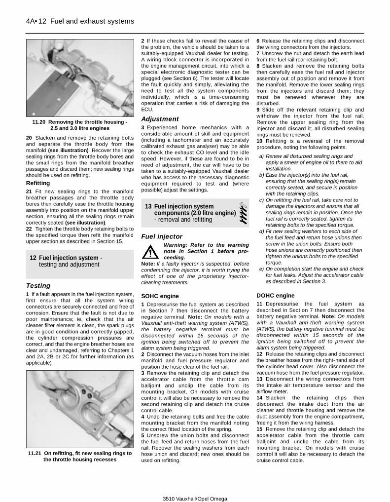
20 Slacken and remove the retaining boltsand separate the throttle body from themanifold (see illustration). Recover the largesealing rings from the throttle body bores andthe small rings from the manifold breatherpassages and discard them; new sealing ringsshould be used on refitting.
Refitting21 Fit new sealing rings to the manifoldbreather passages and the throttle bodybores then carefully ease the throttle housingassembly into position on the manifold uppersection, ensuring all the sealing rings remaincorrectly seated (see illustration).22 Tighten the throttle body retaining bolts tothe specified torque then refit the manifoldupper section as described in Section 15.
12 Fuel injection system -testing and adjustment
Testing1 If a fault appears in the fuel injection system,first ensure that all the system wiringconnectors are securely connected and free ofcorrosion. Ensure that the fault is not due topoor maintenance; ie, check that the aircleaner filter element is clean, the spark plugsare in good condition and correctly gapped,the cylinder compression pressures arecorrect, and that the engine breather hoses areclear and undamaged, referring to Chapters 1and 2A, 2B or 2C for further information (asapplicable).
2 If these checks fail to reveal the cause ofthe problem, the vehicle should be taken to asuitably-equipped Vauxhall dealer for testing.A wiring block connector is incorporated inthe engine management circuit, into which aspecial electronic diagnostic tester can beplugged (see Section 6). The tester will locatethe fault quickly and simply, alleviating theneed to test all the system componentsindividually, which is a time-consumingoperation that carries a risk of damaging theECU.
Adjustment3 Experienced home mechanics with aconsiderable amount of skill and equipment(including a tachometer and an accuratelycalibrated exhaust gas analyser) may be ableto check the exhaust CO level and the idlespeed. However, if these are found to be inneed of adjustment, the car will have to betaken to a suitably-equipped Vauxhall dealerwho has access to the necessary diagnosticequipment required to test and (wherepossible) adjust the settings.
13 Fuel injection systemcomponents (2.0 litre engine)- removal and refitting
4Fuel injector
Warning: Refer to the warningnote in Section 1 before pro-ceeding.
Note: If a faulty injector is suspected, beforecondemning the injector, it is worth trying theeffect of one of the proprietary injector-cleaning treatments.
SOHC engine1 Depressurise the fuel system as describedin Section 7 then disconnect the batterynegative terminal. Note: On models with aVauxhall anti-theft warning system (ATWS),the battery negative terminal must bedisconnected within 15 seconds of theignition being switched off to prevent thealarm system being triggered.2 Disconnect the vacuum hoses from the inletmanifold and fuel pressure regulator andposition the hose clear of the fuel rail.3 Remove the retaining clip and detach theaccelerator cable from the throttle camballjoint and unclip the cable from itsmounting bracket. On models with cruisecontrol it will also be necessary to remove thesecond retaining clip and detach the cruisecontrol cable.4 Undo the retaining bolts and free the cablemounting bracket from the manifold notingthe correct fitted location of the spring.5 Unscrew the union bolts and disconnectthe fuel feed and return hoses from the fuelrail. Recover the sealing washers from eachhose union and discard; new ones should beused on refitting.
6 Release the retaining clips and disconnectthe wiring connectors from the injectors.7 Unscrew the nut and detach the earth leadfrom the fuel rail rear retaining bolt.8 Slacken and remove the retaining boltsthen carefully ease the fuel rail and injectorassembly out of position and remove it fromthe manifold. Remove the lower sealing ringsfrom the injectors and discard them; theymust be renewed whenever they aredisturbed.9 Slide off the relevant retaining clip andwithdraw the injector from the fuel rail.Remove the upper sealing ring from theinjector and discard it; all disturbed sealingrings must be renewed.10 Refitting is a reversal of the removalprocedure, noting the following points.
a) Renew all disturbed sealing rings andapply a smear of engine oil to them to aidinstallation.
b) Ease the injector(s) into the fuel rail,ensuring that the sealing ring(s) remaincorrectly seated, and secure in positionwith the retaining clips.
c) On refitting the fuel rail, take care not todamage the injectors and ensure that allsealing rings remain in position. Once thefuel rail is correctly seated, tighten itsretaining bolts to the specified torque.
d) Fit new sealing washers to each side ofthe fuel feed and return hose unions thenscrew in the union bolts. Ensure bothhose unions are correctly positioned thentighten the unions bolts to the specifiedtorque.
e) On completion start the engine and checkfor fuel leaks. Adjust the accelerator cableas described in Section 3.
DOHC engine11 Depressurise the fuel system asdescribed in Section 7 then disconnect thebattery negative terminal. Note: On modelswith a Vauxhall anti-theft warning system(ATWS), the battery negative terminal must bedisconnected within 15 seconds of theignition being switched off to prevent thealarm system being triggered.12 Release the retaining clips and disconnectthe breather hoses from the right-hand side ofthe cylinder head cover. Also disconnect thevacuum hose from the fuel pressure regulator.13 Disconnect the wiring connectors fromthe intake air temperature sensor and theairflow meter.14 Slacken the retaining clips thendisconnect the intake duct from the aircleaner and throttle housing and remove theduct assembly from the engine compartment,freeing it from the wiring harness.15 Remove the retaining clip and detach theaccelerator cable from the throttle camballjoint and unclip the cable from itsmounting bracket. On models with cruisecontrol it will also be necessary to detach thecruise control cable.
4A•12 Fuel and exhaust systems
11.20 Removing the throttle housing - 2.5 and 3.0 litre engines
11.21 On refitting, fit new sealing rings tothe throttle housing recesses
3510 Vauxhall/Opel Omega

16 Unscrew the nuts and disconnect the fuelfeed hose from its union on the rear of the fuelrail and the return pipe from the front end ofthe fuel rail. As the union nuts are slackened,retain the pipe end fitting with an open-endedspanner to prevent any excess strain beingplaced on the pipe. Plug the hose and pipeends to minimise fuel loss and prevent theentry of dirt then undo the retaining boltsecuring the fuel feed rail pipe to the throttlehousing bracket (see illustrations).17 Disconnect the wiring connector from theidle control stepper motor then undo theretaining bolts and free the cable mountingbracket from the throttle housing, noting thecorrect fitted location of the spring.18 Unscrew the retaining nut and detach theearth lead from the fuel rail front retaining bolt.19 Carefully release the retaining clips and liftoff the injector wiring cover assembly squarelyaway from the top of the injectors; the wiringconnectors are an integral part of the cover.Disconnect the crankshaft sensor and knocksensor wiring connectors (where necessary)from the underside of the injector wiring coverthen position the cover assembly clear of thefuel rail.20 Slacken and remove the retaining boltsthen carefully ease the fuel rail and injectorassembly out of position and remove it fromthe manifold. Remove the lower sealing ringsfrom the injectors and discard them; theymust be renewed whenever they aredisturbed.21 Slide off the relevant retaining clip andwithdraw the injector from the fuel rail.Remove the upper sealing ring from theinjector and discard it; all disturbed sealingrings must be renewed.22 Refitting is a reversal of the removalprocedure, noting the following points.a) Renew all disturbed sealing rings and
apply a smear of engine oil to them to aidinstallation.
b) Ease the injector(s) into the fuel rail,ensuring that the sealing ring(s) remaincorrectly seated, and secure in positionwith the retaining clips. Ensure that theretaining clips are correctly positionedotherwise it will not be possible to refit thewiring cover assembly.
c) On refitting the fuel rail, take care not todamage the injectors and ensure that allsealing rings remain in position. Once thefuel rail is correctly seated, tighten itsretaining bolts to the specified torque.
d) On completion, adjust the acceleratorcable as described in Section 3 then startthe engine and check for fuel leaks.
Fuel pressure regulatorWarning: Refer to the warningnote in Section 1 before pro-ceeding.
23 Depressurise the fuel system asdescribed in Section 7 then disconnect thebattery negative terminal. Note: On modelswith a Vauxhall anti-theft warning system
(ATWS), the battery negative terminal must bedisconnected within 15 seconds of theignition being switched off to prevent thealarm system being triggered.24 Disconnect the vacuum hose from theregulator (see illustration).25 Slacken the retaining clamp then carefullyease the pressure regulator out from the topof the fuel rail. Remove the both sealing ringsfrom the regulator and discard them; newones must be used on refitting.26 Refitting is the reverse of removal, usingnew sealing rings and lubricating them with asmear of engine oil to ease installation. Ensurethe regulator is correctly positioned thentighten the retaining clamp screw to thespecified torque. On completion start theengine and check for signs of fuel leakage.
Idle speed adjuster valve27 On DOHC engines, disconnect the wiringconnectors from the intake air temperaturesensor and the airflow meter then slacken theretaining clips then disconnect the intake ductfrom the air cleaner and throttle housing.Position the duct assembly clear of thethrottle housing to improve access to theadjuster valve.28 On all engines, disconnect the wiringconnector then undo the retaining screws andremove the motor assembly from the side ofthe throttle housing. Remove the gasket anddiscard it; a new one should be used onrefitting.29 Refitting is the reverse of removal using anew gasket.
Throttle potentiometer30 Ensure the ignition is switched off thendisconnect the wiring connector from thethrottle potentiometer which is fitted to thethrottle housing.31 Slacken and remove the retaining screwsthen remove the potentiometer from thehousing (see illustration).32 Refitting is the reverse of removal makingsure the potentiometer is correctly engagedwith the throttle valve spindle.
Coolant temperature sensor
SOHC engine33 The coolant temperature sensor is screwedinto the front, right-hand end of the cylinderhead. Refer to Chapter 3, Section 7 for removaland refitting details noting that it maybenecessary to unbolt the upper mountingbrackets and pivot the alternator away from thecylinder block to gain the necessary clearancerequired to remove the sensor.
DOHC engine34 The coolant temperature sensor isscrewed into the rear of the cylinder headwhere it is located beneath the DIS module.Refer to Chapter 3, Section 7 for removal andrefitting details.
Intake air temperature sensor35 Ensure ignition is switched off then dis-connect the wiring connector from the sensor.36 Slacken the retaining clips then detachthe intake duct from the airflow meter and air
Fuel and exhaust systems 4A•13
4A
13.16a Unscrew the fuel feed pipe unionnut (A) and bolt (B) . . .
13.16b . . . and the fuel return pipe unionnut
13.24 Fuel pressure regulator vacuumhose (1) and retaining clamp (2)
13.31 Disconnect the wiring connector (1)then undo the retaining screws (2) and
remove the throttle potentiometer
3510 Vauxhall/Opel Omega
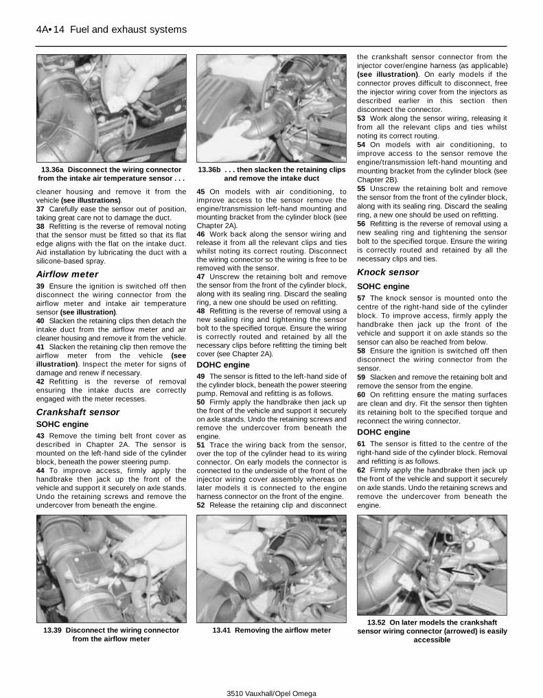
cleaner housing and remove it from thevehicle (see illustrations).37 Carefully ease the sensor out of position,taking great care not to damage the duct.38 Refitting is the reverse of removal notingthat the sensor must be fitted so that its flatedge aligns with the flat on the intake duct.Aid installation by lubricating the duct with asilicone-based spray.
Airflow meter39 Ensure the ignition is switched off thendisconnect the wiring connector from theairflow meter and intake air temperaturesensor (see illustration).40 Slacken the retaining clips then detach theintake duct from the airflow meter and aircleaner housing and remove it from the vehicle.41 Slacken the retaining clip then remove theairflow meter from the vehicle (seeillustration). Inspect the meter for signs ofdamage and renew if necessary.42 Refitting is the reverse of removalensuring the intake ducts are correctlyengaged with the meter recesses.
Crankshaft sensorSOHC engine43 Remove the timing belt front cover asdescribed in Chapter 2A. The sensor ismounted on the left-hand side of the cylinderblock, beneath the power steering pump.44 To improve access, firmly apply thehandbrake then jack up the front of thevehicle and support it securely on axle stands.Undo the retaining screws and remove theundercover from beneath the engine.
45 On models with air conditioning, toimprove access to the sensor remove theengine/transmission left-hand mounting andmounting bracket from the cylinder block (seeChapter 2A).46 Work back along the sensor wiring andrelease it from all the relevant clips and tieswhilst noting its correct routing. Disconnectthe wiring connector so the wiring is free to beremoved with the sensor.47 Unscrew the retaining bolt and removethe sensor from the front of the cylinder block,along with its sealing ring. Discard the sealingring, a new one should be used on refitting.48 Refitting is the reverse of removal using anew sealing ring and tightening the sensorbolt to the specified torque. Ensure the wiringis correctly routed and retained by all thenecessary clips before refitting the timing beltcover (see Chapter 2A).
DOHC engine49 The sensor is fitted to the left-hand side ofthe cylinder block, beneath the power steeringpump. Removal and refitting is as follows.50 Firmly apply the handbrake then jack upthe front of the vehicle and support it securelyon axle stands. Undo the retaining screws andremove the undercover from beneath theengine.51 Trace the wiring back from the sensor,over the top of the cylinder head to its wiringconnector. On early models the connector isconnected to the underside of the front of theinjector wiring cover assembly whereas onlater models it is connected to the engineharness connector on the front of the engine.52 Release the retaining clip and disconnect
the crankshaft sensor connector from theinjector cover/engine harness (as applicable)(see illustration). On early models if theconnector proves difficult to disconnect, freethe injector wiring cover from the injectors asdescribed earlier in this section thendisconnect the connector.53 Work along the sensor wiring, releasing itfrom all the relevant clips and ties whilstnoting its correct routing.54 On models with air conditioning, toimprove access to the sensor remove theengine/transmission left-hand mounting andmounting bracket from the cylinder block (seeChapter 2B).55 Unscrew the retaining bolt and removethe sensor from the front of the cylinder block,along with its sealing ring. Discard the sealingring, a new one should be used on refitting.56 Refitting is the reverse of removal using anew sealing ring and tightening the sensorbolt to the specified torque. Ensure the wiringis correctly routed and retained by all thenecessary clips and ties.
Knock sensor
SOHC engine57 The knock sensor is mounted onto thecentre of the right-hand side of the cylinderblock. To improve access, firmly apply thehandbrake then jack up the front of thevehicle and support it on axle stands so thesensor can also be reached from below.58 Ensure the ignition is switched off thendisconnect the wiring connector from thesensor.59 Slacken and remove the retaining bolt andremove the sensor from the engine.60 On refitting ensure the mating surfacesare clean and dry. Fit the sensor then tightenits retaining bolt to the specified torque andreconnect the wiring connector.
DOHC engine61 The sensor is fitted to the centre of theright-hand side of the cylinder block. Removaland refitting is as follows.62 Firmly apply the handbrake then jack upthe front of the vehicle and support it securelyon axle stands. Undo the retaining screws andremove the undercover from beneath theengine.
4A•14 Fuel and exhaust systems
13.36a Disconnect the wiring connectorfrom the intake air temperature sensor . . .
13.36b . . . then slacken the retaining clipsand remove the intake duct
13.39 Disconnect the wiring connectorfrom the airflow meter
13.41 Removing the airflow meter13.52 On later models the crankshaft
sensor wiring connector (arrowed) is easilyaccessible
3510 Vauxhall/Opel Omega

63 If necessary, to improve access, removethe starter motor as described in Chapter 5A.64 Trace the wiring back from the sensor toits wiring connector. On early models theconnector is connected to the underside ofthe injector wiring cover assembly (in betweennumber 3 and 4 injectors) whereas on latermodels it is connected to the engine harnessconnector located on the underside of theinlet manifold.65 Release the retaining clip and disconnectthe crankshaft sensor connector from theinjector cover/engine harness (as applicable).On early models if the connector provesdifficult to disconnect, free the injector wiringcover from the injectors as described earlier inthis section then disconnect the connector.66 Work along the sensor wiring, releasing itfrom all the relevant clips and ties whilstnoting its correct routing.67 Slacken and remove the retaining bolt andremove the sensor from the engine.68 On refitting ensure the mating surfacesare clean and dry then fit the sensor andtighten its retaining bolt to the specifiedtorque. Ensure the wiring is correctly routedand securely reconnected.
Camshaft sensor - DOHC engine69 Undo the retaining screws and removethe spark plug cover from the top of thecylinder head cover.70 Ensure the ignition is switched off thendisconnect the wiring connector from thecamshaft sensor.71 Remove the timing belt front cover asdescribed in Chapter 2B.
72 Unscrew the retaining bolt and removethe camshaft sensor from the top of thecylinder head.73 Refitting is the reverse of removaltightening the sensor retaining bolt to thespecified torque.
Electronic control unit (ECU)74 Disconnect the battery negative terminalthen unclip the lid from the enginecompartment relay box. Note: On modelswith a Vauxhall anti-theft warning system(ATWS), the battery negative terminal must bedisconnected within 15 seconds of theignition being switched off to prevent thealarm system being triggered.75 Slide the ECU out of position until accessto the wiring connector retaining clip can begained. Lift the retaining clip and carefullydisconnect the wiring connector then removethe ECU from the vehicle (see illustrations). Ifnecessary, undo the retaining nuts andseparate the ECU from its mounting plate.76 Refitting is the reverse of removal makingsure the wiring connector is correctlyreconnected. On later DOHC engines (withSimtec 56.5 system) if a new ECU has beenfitted it will be necessary to take the vehicle toa Vauxhall dealer to have the unit coded tomatch the performance of your engine.
Injection system relays77 The injection system relays are located inthe engine compartment relay box.78 Unclip the lid from the relay box. Theinjection system relays are the two relayssituated at the rear of the box; the fuel pump
relay is the right-hand (inner) relay of the twoand the injection system/protection relay isthe left-hand (outer) relay (see illustration).79 Ensure the ignition is switched off thenpull the relevant relay out of its socket andremove it from the vehicle (see illustration).80 Refitting is the reverse of removal.
Air conditioning system switch81 The air conditioning system switch isscrewed into one of the refrigerant pipes andcannot be removed without first dischargingthe refrigerant (see Chapter 3). Renewal of theswitch should therefore be entrusted to asuitably equipped garage.
14 Fuel injection system components(2.5 and 3.0 litre engines) -removal and refitting
4Fuel injector
Warning: Refer to the warningnote in Section 1 before pro-ceeding.
Note: If a faulty injector is suspected, beforecondemning the injector, it is worth trying theeffect of one of the proprietary injector-cleaning treatments.1 Remove the lower section of the inletmanifold as described in Section 15.2 Depress the retaining clips and disconnectthe wiring connectors from the six injectors.Unclip the wiring harness cover from the topof the fuel rail and remove it from the manifold(see illustrations).
Fuel and exhaust systems 4A•15
4A
13.75a Slide out the ECU then lift theretaining clip . . .
13.75b . . . and disconnect its wiringconnector
13.78 The fuel pump relay (1) and injectionsystem relay (2) are located in the engine
compartment relay box
13.79 Removing the fuel pump relay 14.2a Disconnect the wiring connectorsfrom the injectors . . .
14.2b . . . then unclip the cover assemblyfrom the fuel rail
3510 Vauxhall/Opel Omega

3 Slacken the union nuts securing the fuelpipes to the fuel rail whilst (where possible)retaining the fuel rail with an open-endedspanner. Unscrew the retaining bolts andremove the pipe assembly from the manifoldlower section (see illustrations).4 Slacken and remove the retaining boltsthen carefully ease the fuel rail and injectorassembly out from the manifold. Remove thelower sealing rings from the injectors anddiscard them. Slide off the relevant retainingclip and withdraw the injector from the fuelrail. Remove the upper sealing ring from theinjector and discard it. All disturbed sealingrings must be renewed (see illustrations).5 Refitting is a reversal of the removalprocedure, noting the following points.a) Renew all disturbed sealing rings and
apply a smear of engine oil to them to aidinstallation (see illustration).
b) Ease the injector(s) into the fuel rail,
ensuring that the sealing ring(s) remaincorrectly seated, and secure in positionwith the retaining clips.
c) On refitting the fuel rail, take care not todamage the injectors and ensure that allsealing rings remain in position. Once thefuel rail is correctly seated, tighten itsretaining bolts to the specified torque.
d) Tighten the fuel pipe union nuts andretaining bolts to the specified torquethen refit the wiring cover assemblymaking sure all the wiring connectors aresecurely reconnected.
e) Refit the manifold as described in Section15. On completion start the engine andcheck for fuel leaks.
Fuel pressure regulatorWarning: Refer to the warningnote in Section 1 before pro-ceeding.
6 Depressurise the fuel system as describedin Section 7 then disconnect the batterynegative terminal. Note: On models with aVauxhall anti-theft warning system (ATWS),the battery negative terminal must bedisconnected within 15 seconds of theignition being switched off to prevent thealarm system being triggered.7 To gain access to the pressure regulator,remove the windscreen wiper arms and thewater deflector panel from the base of thewindscreen (see Chapter 12, Sections 15and 16) (see illustration).8 Unclip the wiring connector holder from thelifting bracket on the rear of the cylinder headand position the wiring clear of the regulator.9 Disconnect the vacuum hose from the fuelpressure regulator.10 Slacken the retaining clamp then carefullyease the pressure regulator out from the fuelrail. Remove both sealing rings from the
4A•16 Fuel and exhaust systems
14.3a Slacken the union nuts . . . 14.3b . . . then undo the retaining bolts(arrowed) . . .
14.3c . . . and remove the fuel pipes fromthe manifold
14.4d . . . then ease the injector out fromthe fuel rail
14.5 On refitting be sure to renew allinjector sealing rings
14.7 The fuel pressure regulator is locatedat the rear of the inlet manifold (shown with engine removed)
14.4a Undo the retaining bolts (arrowed) . . .
14.4b . . . and ease the fuel rail andinjector assembly out of position
14.4c Slide off the relevant retaining clip . . .
3510 Vauxhall/Opel Omega

regulator and discard them; new ones mustbe used on refitting.11 Refitting is the reverse of removal, usingnew sealing rings and lubricating them with asmear of engine oil to ease installation. Ensurethe regulator is correctly positioned thensecurely tighten the retaining clamp screw.On completion start the engine and check forsigns of fuel leakage.
Idle speed adjuster valve12 Ensure the ignition is switched off thendisconnect the wiring connector from thevalve which is fitted to the left-hand side ofthe inlet manifold (see illustration).13 Slacken the retaining clip and disconnectthe hose from the valve then carefully easethe valve assembly out from the manifold (seeillustration). If necessary separate the valveand its mounting rubber. Inspect themounting rubber for signs of damage ordeterioration and renew if necessary.14 Refitting is the reverse of removal makingsure the mounting rubber grommet is correctlypositioned. Aid installation by lubricating thegrommet with a silicone-based spray.On completion start the engine and check forair leaks.
Throttle potentiometer15 Ensure the ignition is switched off thendisconnect the wiring connector from thethrottle potentiometer which is fitted to theleft-hand side of the throttle housing (seeillustration).
16 Slacken and remove the retaining screwsthen remove the potentiometer from thehousing.17 Refitting is the reverse of removal makingsure the potentiometer is correctly engagedwith the throttle valve spindle.
Coolant temperature sensor18 The coolant temperature sensor isscrewed into the coolant outlet which links therear of the cylinder heads. Refer to Chapter 3for removal and refitting details noting that itwill be necessary to remove the inlet manifoldto gain access to the sensor (seeillustration).
Intake air temperature sensor19 Ensure ignition is switched off thendisconnect the wiring connector from thesensor.20 Slacken the retaining clips then detachthe intake duct from the airflow meter and aircleaner housing and remove it from thevehicle (see illustration).21 Carefully ease the sensor out of positionand recover is sealing grommet. Inspect thegrommet for signs of damage or deteriorationand renew if necessary.22 Refitting is the reverse of removal makingsure the sensor and grommet are correctlyseated.
Airflow meter23 Ensure the ignition is switched off thendisconnect the wiring connectors from the
airflow meter and intake air temperaturesensor.24 Slacken the retaining clips then detachthe intake duct from the airflow meter and aircleaner housing and remove it from thevehicle.25 Slacken the retaining clip then remove theairflow meter from the vehicle. Inspect themeter for signs of damage and renew ifnecessary.26 Refitting is the reverse of removalensuring the intake ducts are correctlyengaged with the meter recesses.
Crankshaft sensor27 The sensor is mounted on the left-handside of the cylinder block, directly below theoil filter, and its wiring connector is clippedonto the holder on the rear of the left handcylinder head.28 To gain access to the wiring connector,remove the windscreen wiper arms and thewater deflector panel from the base of the wind-screen (see Chapter 12, Sections 15 and 16).29 Ensure the ignition is switched off thenunclip the sensor wiring connector from itsholder and disconnect it (see illustration).30 Firmly apply the handbrake then jack upthe front of the vehicle and support it on axlestands.31 Work back along the sensor wiring andrelease it from all the relevant clips and tieswhilst noting its correct routing.32 Unscrew the retaining bolt and removethe sensor from the cylinder block, along with
Fuel and exhaust systems 4A•17
4A
14.12 Disconnect the wiring connectorfrom the idle speed adjuster valve . . .
14.13 . . . then release the retaining clipand detach the air hose
14.15 Disconnecting the throttlepotentiometer wiring connector
14.18 The coolant temperature sensor isscrewed into the coolant outlet (shown
with inlet manifold removed)
14.20 Disconnect the wiring connectorfrom the intake air sensor then release theretaining clips (arrowed) and remove the
intake duct
14.29 The crankshaft sensor wiringconnector (arrowed) is clipped onto theengine rear lifting bracket (shown with
engine removed)
3510 Vauxhall/Opel Omega

its sealing ring. Discard the sealing ring, a newone should be used on refitting (seeillustration).33 Refitting is the reverse of removal using anew sealing ring and tightening the sensorbolt to the specified torque. Ensure the wiringis correctly routed and retained by all thenecessary clips so that it is in no danger ofcontacting the exhaust manifold.
Knock sensor - right-hand cylinder bank34 Remove the auxiliary drivebelt asdescribed in Chapter 1 then unbolt thedrivebelt tensioner pulley assembly from theside of the cylinder head.35 Remove the alternator upper mountingbolt then slacken the lower mounting andpivot the alternator away from the block (seeChapter 5A).36 Trace the wiring back from the sensor tothe front of the timing belt cover, releasing itfrom all the relevant clips and ties whilstnoting its correct routing. Ensure the ignitionis switched off then disconnect the sensorwiring connector.37 Slacken and remove the retaining bolt andremove the sensor from the engine (seeillustration).38 On refitting ensure the mating surfacesare clean and dry then fit the sensor andtighten its retaining bolt to the specifiedtorque. Ensure the wiring is correctly routedand securely retained by all the necessaryclips so that it is no danger of contacting theauxiliary drivebelt. Refit the alternator and
drivebelt tensioner, tightening their retainingbolts to the specified torque settings (seeChapter 5A) and refit the auxiliary drivebelt(see Chapter 1).
Knock sensor - left-hand cylinder bank39 The knock sensor is situated on the left-hand side of the cylinder block, just in front ofthe oil filter and is wiring connector isconnected to the wiring harness cover abovethe left-hand cylinder head. To gain access tothe sensor, firmly apply the handbrake thenjack up the front of the vehicle and support iton axle stands.40 On models with air conditioning, toimprove access to the sensor remove theengine/transmission left-hand mounting andmounting bracket from the cylinder block (seeChapter 2C).41 Trace the wiring back from the sensor,releasing it from all the relevant clips and tieswhilst noting its correct routing. Disconnectthe wiring connector and tie a length of stringto it; the string can then be used on refitting todraw the wiring connector up and intoposition.42 Slacken and remove the retaining bolt andremove the sensor from the engine. Untie thestring and leave in position for use on refitting.43 On refitting then use the string to draw thewiring connector up and into position. Ensurethe mating surfaces are clean and dry then fitthe sensor and tighten its retaining bolt to thespecified torque (see illustration). Ensure thewiring is correctly routed and securely
retained by all the necessary clips so that it isno danger of contacting the exhaust systemor auxiliary drivebelt. On models with airconditioning refit the engine mounting bracketand mounting as described in Chapter 2C.
Camshaft sensor44 The sensor is mounted onto the top of theleft-hand cylinder bank exhaust camshaftwhere it is directly behind the timing beltcover. On models with air conditioning, toimprove access to the sensor, unbolt the airconditioning pipe/hose bracket from thecylinder head and position the hose/pipe toone side.45 Ensure the ignition is switched off thendisconnect the wiring connector from thecamshaft sensor46 Unscrew the retaining bolt and removethe camshaft sensor from the camshaftbearing cap (see illustration).47 Refitting is the reverse of removaltightening the sensor retaining bolt to thespecified torque.
Electronic control unit (ECU)48 Refer to Section 13.
Injection system relays49 Refer to Section 13.
Air conditioning system switch50 The air conditioning system switch isscrewed into one of the refrigerant pipes andcannot be removed without first dischargingthe refrigerant (see Chapter 3). Renewal of theswitch should therefore be entrusted to asuitably equipped garage.
15 Inlet manifold - removal and refitting 4
Warning: Refer to the warningnote in Section 1 before pro-ceeding.
2.0 litre SOHC engine
Removal1 Depressurise the fuel system as describedin Section 7 then disconnect the batterynegative terminal. Note: On models with aVauxhall anti-theft warning system (ATWS),the battery negative terminal must bedisconnected within 15 seconds of theignition being switched off to prevent thealarm system being triggered.2 Remove the auxiliary drivebelt and drain thecooling system as described in Chapter 1.3 Disconnect the wiring connectors from theintake air temperature sensor and the airflowmeter.4 Slacken the retaining clips then disconnectthe intake duct from the air cleaner andthrottle housing and remove the ductassembly from the engine compartment.5 Remove the retaining clip and detach the
4A•18 Fuel and exhaust systems
14.32 Removing the crankshaft sensor(shown with oil filter removed)
14.37 Unscrew the retaining bolt andremove the knock sensor from the right-
hand side of the cylinder block
14.43 On refitting ensure the knock sensoris correctly positioned then tighten itsretaining bolt to the specified torque
14.46 Removing the camshaft sensor
3510 Vauxhall/Opel Omega
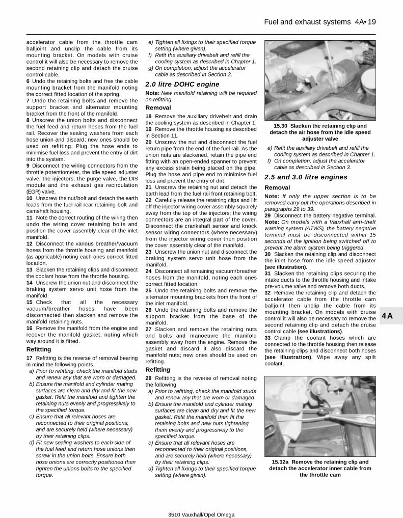
accelerator cable from the throttle camballjoint and unclip the cable from itsmounting bracket. On models with cruisecontrol it will also be necessary to remove thesecond retaining clip and detach the cruisecontrol cable.6 Undo the retaining bolts and free the cablemounting bracket from the manifold notingthe correct fitted location of the spring.7 Undo the retaining bolts and remove thesupport bracket and alternator mountingbracket from the front of the manifold.8 Unscrew the union bolts and disconnectthe fuel feed and return hoses from the fuelrail. Recover the sealing washers from eachhose union and discard; new ones should beused on refitting. Plug the hose ends tominimise fuel loss and prevent the entry of dirtinto the system.9 Disconnect the wiring connectors from thethrottle potentiometer, the idle speed adjustervalve, the injectors, the purge valve, the DISmodule and the exhaust gas recirculation(EGR) valve.10 Unscrew the nut/bolt and detach the earthleads from the fuel rail rear retaining bolt andcamshaft housing.11 Note the correct routing of the wiring thenundo the wiring cover retaining bolts andposition the cover assembly clear of the inletmanifold.12 Disconnect the various breather/vacuumhoses from the throttle housing and manifold(as applicable) noting each ones correct fittedlocation.13 Slacken the retaining clips and disconnectthe coolant hose from the throttle housing.14 Unscrew the union nut and disconnect thebraking system servo unit hose from themanifold.15 Check that all the necessaryvacuum/breather hoses have beendisconnected then slacken and remove themanifold retaining nuts.16 Remove the manifold from the engine andrecover the manifold gasket, noting whichway around it is fitted.
Refitting17 Refitting is the reverse of removal bearingin mind the following points.a) Prior to refitting, check the manifold studs
and renew any that are worn or damaged.b) Ensure the manifold and cylinder mating
surfaces are clean and dry and fit the newgasket. Refit the manifold and tighten theretaining nuts evenly and progressively tothe specified torque.
c) Ensure that all relevant hoses arereconnected to their original positions,and are securely held (where necessary)by their retaining clips.
d) Fit new sealing washers to each side ofthe fuel feed and return hose unions thenscrew in the union bolts. Ensure bothhose unions are correctly positioned thentighten the unions bolts to the specifiedtorque.
e) Tighten all fixings to their specified torquesetting (where given).
f) Refit the auxiliary drivebelt and refill thecooling system as described in Chapter 1.
g) On completion, adjust the acceleratorcable as described in Section 3.
2.0 litre DOHC engineNote: New manifold retaining will be requiredon refitting.
Removal18 Remove the auxiliary drivebelt and drainthe cooling system as described in Chapter 1.19 Remove the throttle housing as describedin Section 11.20 Unscrew the nut and disconnect the fuelreturn pipe from the end of the fuel rail. As theunion nuts are slackened, retain the pipe endfitting with an open-ended spanner to preventany excess strain being placed on the pipe.Plug the hose and pipe end to minimise fuelloss and prevent the entry of dirt.21 Unscrew the retaining nut and detach theearth lead from the fuel rail front retaining bolt.22 Carefully release the retaining clips and liftoff the injector wiring cover assembly squarelyaway from the top of the injectors; the wiringconnectors are an integral part of the cover.Disconnect the crankshaft sensor and knocksensor wiring connectors (where necessary)from the injector wiring cover then positionthe cover assembly clear of the manifold.23 Unscrew the union nut and disconnect thebraking system servo unit hose from themanifold.24 Disconnect all remaining vacuum/breatherhoses from the manifold, noting each onescorrect fitted location.25 Undo the retaining bolts and remove thealternator mounting brackets from the front ofthe inlet manifold.26 Undo the retaining bolts and remove thesupport bracket from the base of themanifold.27 Slacken and remove the retaining nutsand bolts and manoeuvre the manifoldassembly away from the engine. Remove thegasket and discard it also discard themanifold nuts; new ones should be used onrefitting.
Refitting28 Refitting is the reverse of removal notingthe following.a) Prior to refitting, check the manifold studs
and renew any that are worn or damaged.b) Ensure the manifold and cylinder mating
surfaces are clean and dry and fit the newgasket. Refit the manifold then fit theretaining bolts and new nuts tighteningthem evenly and progressively to thespecified torque.
c) Ensure that all relevant hoses arereconnected to their original positions,and are securely held (where necessary)by their retaining clips.
d) Tighten all fixings to their specified torquesetting (where given).
e) Refit the auxiliary drivebelt and refill thecooling system as described in Chapter 1.
f) On completion, adjust the acceleratorcable as described in Section 3.
2.5 and 3.0 litre engines
RemovalNote: If only the upper section is to beremoved carry out the operations described inparagraphs 29 to 39.29 Disconnect the battery negative terminal.Note: On models with a Vauxhall anti-theftwarning system (ATWS), the battery negativeterminal must be disconnected within 15seconds of the ignition being switched off toprevent the alarm system being triggered.30 Slacken the retaining clip and disconnectthe inlet hose from the idle speed adjuster(see illustration).31 Slacken the retaining clips securing theintake ducts to the throttle housing and intakepre-volume valve and remove both ducts.32 Remove the retaining clip and detach theaccelerator cable from the throttle camballjoint then unclip the cable from itsmounting bracket. On models with cruisecontrol it will also be necessary to remove thesecond retaining clip and detach the cruisecontrol cable (see illustrations).33 Clamp the coolant hoses which areconnected to the throttle housing then releasethe retaining clips and disconnect both hoses(see illustration). Wipe away any spiltcoolant.
Fuel and exhaust systems 4A•19
4A
15.30 Slacken the retaining clip anddetach the air hose from the idle speed
adjuster valve
15.32a Remove the retaining clip anddetach the accelerator inner cable from
the throttle cam
3510 Vauxhall/Opel Omega

34 Disconnect the wiring connectors fromthe throttle valve potentiometer, the idlespeed adjuster, the inlet manifold switchovervalve solenoid and the exhaust gasrecirculation (EGR) valve.
35 Unscrew the union nut and disconnect thepipe from the EGR valve then unscrew theretaining bolt and free the pipe bracket fromthe valve (see illustrations). Wherenecessary, disconnect the connector and freethe knock sensor wiring connector from theEGR valve bracket.36 Unscrew the union nut and disconnect thebraking system servo unit vacuum hose fromthe manifold upper section (see illustration).37 Make a note of the correct fitted locationsof the vacuum/breather hoses connected tothe rear of the manifold upper section thenrelease the retaining clips (where fitted) anddisconnect them (see illustration).38 Unscrew the retaining bolts and detachthe hose/wiring brackets from the corners ofthe manifold upper section (see illustration).39 Remove the caps from the top of themanifold then slacken and remove the upper
section retaining bolts. Lift off the manifoldupper section, disconnecting the vacuumhoses from the manifold switchover solenoidvalve as they become accessible (seeillustrations). Remove the sealing rings fromthe top of manifold lower section and discardthem; new ones should be used on refitting.Caution: Take great care not to allow anyforeign object to drop down into thecylinder head intake ports.40 Depressurise the fuel system (Section 7)then unscrew the nuts and disconnect the fuelfeed and return hoses from their unions on theright-hand side of the manifold. As each unionnut is slackened, retain the pipe end fittingwith an open-ended spanner to prevent anyexcess strain being placed on the pipes (seeillustration). Plug the hose and pipe ends tominimise fuel loss and prevent the entry ofdirt.
4A•20 Fuel and exhaust systems
15.32b On models with cruise controlprise off the second retaining clip . . .
15.32c . . . and free the cruise controlcable from the throttle cam and bracket
15.33 Release the retaining clips anddetach the coolant hoses (arrowed) from
the throttle housing
15.38 Undo the retaining bolts and free thehose/wiring brackets from the manifold
15.39a Remove the caps then unscrew theretaining bolts . . .
15.39b . . . and remove the manifold uppersection
15.35b . . . then remove the bracketretaining bolt
15.35a Unscrew the union nut and free theEGR pipe from the EGR valve
15.36 Unscrew the union nut anddisconnect the braking system servo unit
hose
15.37 Release the retaining clips anddisconnect the vacuum and breatherhoses from the rear of the manifold
3510 Vauxhall/Opel Omega

41 Disconnect the injector wiring harnessconnector and the vacuum hose from the fuelpressure regulator (see illustration).42 Slacken and remove the retaining boltsthen lift the manifold lower section away fromthe cylinder head. Remove the seals from themanifold flange recesses and discard them;new ones must be used on refitting (seeillustrations).43 If necessary, undo the retaining bolts andremove the intake manifold flange from thetop of the cylinder head (see illustration).Recover the flange seals and discard them;new ones must be used on refitting.
Refitting44 Refitting is the reverse of removal notingthe following.a) Ensure all the mating surfaces are clean
and dry and the new seals/sealing ringsare correctly seated in their recesses (seeillustration). Tighten all the manifoldretaining bolts evenly and progressively totheir specified torque settings.
b) Ensure that all relevant hoses arereconnected to their original positions,and are securely held (where necessary)by their retaining clips.
c) Tighten the fuel hose and vacuum servohose union nuts to their specified torquesettings.
d) Ensure the EGR valve and pipe matingsurfaces are clean and dry and apply asmear of high-temperature grease to thethreads of the union nut (Vauxhall recom-mend the use of assembly paste 19 48 569- available from your Vauxhall dealer).
Reconnect the pipe to the valve andtighten its union nut to the specifiedtorque.
e) On completion, adjust the acceleratorcable as described in Section 3.
16 Exhaust manifold - removal and refitting 4
Note: New manifold nuts will be required onrefitting.
2.0 litre SOHC engine
Removal1 Firmly apply the handbrake then jack up thefront of the vehicle and support it on axlestands. If necessary, to improve access undothe retaining bolts and remove the undercoverfrom beneath the engine.2 Slacken and remove the bolt(s) securing theexhaust system front pipe to its mountingbracket then unscrew the bolts securing thefront pipe to the manifold. Free the pipe fromthe manifold taking care not to place anystrain on the oxygen sensor wiring. Discardthe front pipe gasket; a new one should beused on refitting.3 Undo the retaining bolts and remove theheatshield from the exhaust manifold.4 Remove the engine oil dipstick and pull theplug caps off from the centre (No 2 and 3)spark plugs. Unscrew the centre spark plugheatshields and remove them from the
manifold (a special socket, number KM-834, isavailable to ease removal of the heatshields).5 Undo the retaining nuts securing themanifold to the head. Manoeuvre the manifoldout of the engine compartment, complete withthe gasket. Discard both the gasket andretaining nuts; new ones should be used onrefitting.
Refitting6 Examine all the exhaust manifold studs forsigns of damage and corrosion; remove alltraces of corrosion, and repair or renew anydamaged studs.7 Ensure that the manifold and cylinder headsealing faces are clean and flat, and fit thenew gasket.8 Refit the manifold then fit the new retainingnuts and tighten them to the specified torque.9 Apply a smear of high-temperature grease(Vauxhall recommend the use of assemblypaste 19 48 569 - available from your Vauxhalldealer) to the threads of the spark plugheatshields then refit the shields and tightenthem to the specified torque. Reconnect theplug caps and refit the dipstick.10 Apply the high-temperature grease to theheatshield bolts then refit the heatshield to themanifold and securely tighten the bolts.11 Fit a new gasket to the exhaust front pipejoint and lubricate the front pipe to manifoldbolts with the high-temperature grease. Refitthe bolts to the manifold, tightening them tothe specified torque, then securely tighten thebolt(s) securing the front pipe to its mountingbracket.
Fuel and exhaust systems 4A•21
4A
15.40 Unscrew the union nuts anddisconnect the fuel feed and return hoses
from the manifold
15.41 The injector wiring harnessconnector (arrowed) is clipped onto theengine rear lifting bracket (shown with
engine removed)
15.42a Remove the manifold lower section . . .
15.42b . . . and recover the seals (arrowed)from the flange
15.43 Removing the manifold flange 15.44 On refitting be sure to renew allmanifold seals and sealing rings
3510 Vauxhall/Opel Omega

2.0 litre DOHC engine
Removal12 Remove the secondary air injectionsystem air valve and connecting pipe asdescribed in Chapter 4B.13 Carry out the operations described inparagraphs 1 and 2.14 Undo the retaining nuts then remove theexhaust manifold and gasket from the cylinderhead. Discard both the gasket and retainingnuts; new ones should be used on refitting.
Refitting15 Refit the manifold as described inparagraphs 6 to 8.16 Fit a new gasket to the exhaust front pipejoint and lubricate the front pipe to manifoldbolts with high-temperature grease (Vauxhallrecommend the use of assembly paste 19 48569 - available from your Vauxhall dealer).
Refit the bolts to the manifold, tightening themto the specified torque, then securely tightenthe bolt(s) securing the front pipe to itsmounting bracket.17 Refit the secondary air injection systemconnecting pipe and air valve as described inChapter 4B.
2.5 and 3.0 litre engine
Right-hand cylinder bank18 Remove the inlet manifold and flange asdescribed in Section 15.19 Drain the cooling system as described inChapter 1.20 Disconnect the wiring connectors fromthe coolant temperature gauge sender andthe engine management system coolanttemperature sensor which are screwed intothe coolant outlet which links the rear of thecylinder heads (see illustration).
21 Slacken the retaining clips and disconnectthe coolant hoses from the cylinder headoutlet (see illustration).22 Unscrew the retaining bolts and removethe coolant outlet from the cylinder heads(see illustration). Recover the sealing ringsand discard them; new ones must be used onrefitting.23 Position a container beneath the oil filter.Unscrew the filter using an oil filter removal toolif necessary, and drain the oil into the container.If the oil filter is damaged or distorted duringremoval, it must be renewed. Given the low costof a new oil filter relative to the cost of repairingthe damage which could result if a re-used filtersprings a leak, it is probably a good idea torenew the filter in any case.24 Unscrew the union nuts securing the oilcooler pipes to the cylinder block thenunscrew the union bolts securing the pipes tothe cooler. Recover the sealing washers fromeach side of the oil cooler unions and movethe pipes to the rear (see illustrations).25 Release the retaining clips and disconnectthe radiator bottom hose, expansion tank hoseand heater hose from the coolant pipe on theright-hand side of the engine. Slacken andremove the retaining bolts then remove the pipefrom the engine (see illustration). Recover thesealing ring and discard it; a new one should beused on refitting. Note that it maybe necessaryto remove the camshaft cover from the right-hand cylinder head to gain the clearancerequired to remove the coolant pipe.26 Undo the retaining bolts and remove theheatshields from the exhaust manifold (seeillustrations).
4A•22 Fuel and exhaust systems
16.20 Disconnect the wiring connectorsfrom the coolant sensor and sender . . .
16.21 . . . then release the retaining clipsand disconnect the coolant hoses
16.22 Unscrew the retaining bolts andremove the coolant outlet from the engine
(sealing rings arrowed)
16.25 Removing the engine coolant pipe 16.26a Undo the retaining bolts andremove the lower . . .
16.24a Unscrew the union nuts securingthe oil pipes to the block . . .
16.24b . . . then unscrew the union boltsand detach the pipes from the oil cooler
(sealing washers arrowed)
16.26b . . . and upper heatshields from theright-hand exhaust manifold
3510 Vauxhall/Opel Omega

27 Slacken and remove the bolt securing theexhaust system right-hand front pipe to itsmounting bracket then unscrew the boltssecuring the pipe to the manifold. Free thepipe from the manifold taking care not toplace any strain on the oxygen sensor wiring,and recover the gasket. Discard the front pipegasket; a new one should be used on refitting.28 Unscrew the union nuts and remove thepipe connecting the exhaust gas recirculation(EGR) valve to the manifold.29 Slacken the clip securing the connectinghose to the right-hand cylinder banksecondary air injection system pipe thenunscrew the bolts securing the pipe to themanifold. Remove the pipe from the vehicleand discard its gaskets (see illustration).30 Undo the retaining nuts then remove theexhaust manifold and gasket from the cylinderhead. Discard both the gasket and retainingnuts; new ones should be used on refitting.31 Refitting is the reverse of removal, notingthe following points.a) Prior to refitting, check the manifold studs
and renew any that are worn or damaged.b) Ensure all mating surfaces are clean and
dry and use new gaskets, sealing ringsand washers.
c) Secure the manifold in position with newretaining nuts, tightening them evenly andprogressively to the specified torque.
d) Prior to refitting, lubricate the threads ofthe secondary air injection system pipebolts, the EGR valve pipe nuts, the frontpipe to manifold bolts and the heatshieldbolts with a smear of high-temperaturegrease (Vauxhall recommend the use ofassembly paste 19 48 569 - available fromyour Vauxhall dealer).
e) Tighten all fixings to their specified torquesetting (where given).
f) Ensure that all relevant hoses arereconnected to their original positions,and are securely held (where necessary)by their retaining clips.
g) Fit new sealing washers to each side ofthe oil cooler pipe unions and tighten thepipe union nuts and bolts to the specifiedtorque.
i) Fit a new oil filter and refill the coolingsystem as described in Chapter 1.
j) On completion, check the engine oil levelas described in Weekly checks.
Left-hand cylinder bank32 It is not possible to remove the exhaustmanifold from the left-hand cylinder bank withthe engine in the vehicle. This leaves twopossible options, the first is to remove theengine unit from the vehicle and the second isto remove the cylinder head assembly. Decideon the course of action which is best suitedthen proceed as follows.33 Working as described in Chapter 2C,either remove the engine unit from the vehicleor alternatively remove the cylinder headassembly from the engine.34 If the engine has been removed, unscrew
the bolt and spacer securing the coolant pipeand engine lifting bracket to the cylinder headand remove the lifting bracket. Free thecoolant pipe from the thermostat housingthen manoeuvre it out of position thenwithdraw the dipstick and ease the dipsticktube out from the cylinder block. Discard thecoolant pipe and dipstick tube sealing rings;new ones should be used on refitting.35 Undo the retaining bolts and remove theheatshields from the exhaust manifold.36 Unscrew the retaining bolts and removethe secondary air injection system pipe fromthe manifold. Recover the gaskets fittedbetween the pipe and manifold and discardthem.37 Undo the retaining nuts then remove theexhaust manifold and gasket from the cylinderhead. Discard both the gasket and retainingnuts; new ones should be used on refitting.38 Refitting is the reverse of removal, notingthe following points.a) Prior to refitting, check the manifold studs
and renew any that are worn or damaged.b) Ensure the manifold and cylinder head
mating surfaces are clean and dry then fitthe new gasket. Refit the manifold then fitthe new retaining nuts, tightening themevenly and progressively to the specifiedtorque.
c) Lubricate the threads of the secondary airinjection system pipe bolts with a smear ofhigh-temperature grease (Vauxhall recom-mend the use of assembly paste 19 48 569- available from your Vauxhall dealer). Fit
new gaskets to the pipe unions then refitthe pipe to the cylinder head and tightenthe retaining bolts to the specified torque(see Chapter 4B).
d) Lubricate the manifold heatshield boltswith the high-temperature grease beforeinstallation.
e) If the engine was removed, fit new sealingrings to the dipstick tube and thermostathousing coolant pipe. Ensure the coolantpipe, dipstick tube and lifting bracket arecorrectly positioned before refitting theretaining bolt and spacer and tighteningto the specified torque.
17 Multi-ram air intake system -information and componentremoval and refitting
3Information1 All 2.5 and 3.0 litre engines are fitted with amulti-ram air intake system to help increasetorque output at all engine speeds. Thesystem consists of the pre-volume chamber,which splits the air cleaner intake duct intotwo separate ducts, and two valves, onelinking the intake ducts in between the pre-volume chamber and throttle housing, and thesecond linking the left- and right-handchambers of the inlet manifold upper section.Each valve is controlled the enginemanagement ECU via a solenoid valve andvacuum diaphragm unit.2 There are four possible combinations ofvalve position, each of which is suited to aparticular engine speed range, they are asfollows.a) Idle speed - intake duct valve closed,
manifold valve openb) Full load at low engine speeds - intake
duct and manifold valves both closed.c) Full load at medium engine speeds -
intake duct valve open, manifold valveclosed.
d) Full load at high engine speeds - intakevalve and manifold valve both open.
3 Testing of the system can only be carriedout using the special electronic diagnostictest unit which is plugged into the system’sdiagnostic connector (see Section 6). Themulti-ram intake system components can beremoved and refitted as follows.
Component removal andrefitting
Intake duct switchover valve solenoidvalve4 The intake duct switchover valve solenoidvalve is mounted onto the rear of the pre-volume chamber (see illustration).5 Ensure the ignition is switched off thendisconnect the wiring connector from thevalve.6 Disconnect the vacuum pipes from thevalve, noting their correct fitted locations,
Fuel and exhaust systems 4A•23
4A
16.29 Undo the retaining bolts and removethe secondary air connecting pipe
17.4 The intake duct switchover valvesolenoid valve (arrowed) is mounted on the
rear of the pre-volume chamber (shownwith chamber removed)
3510 Vauxhall/Opel Omega
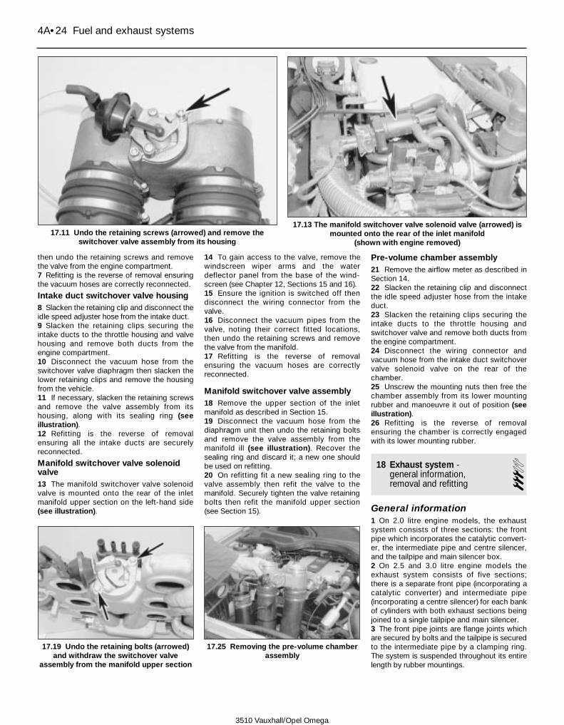
then undo the retaining screws and removethe valve from the engine compartment.7 Refitting is the reverse of removal ensuringthe vacuum hoses are correctly reconnected.
Intake duct switchover valve housing8 Slacken the retaining clip and disconnect theidle speed adjuster hose from the intake duct.9 Slacken the retaining clips securing theintake ducts to the throttle housing and valvehousing and remove both ducts from theengine compartment.10 Disconnect the vacuum hose from theswitchover valve diaphragm then slacken thelower retaining clips and remove the housingfrom the vehicle.11 If necessary, slacken the retaining screwsand remove the valve assembly from itshousing, along with its sealing ring (seeillustration).12 Refitting is the reverse of removalensuring all the intake ducts are securelyreconnected.
Manifold switchover valve solenoidvalve13 The manifold switchover valve solenoidvalve is mounted onto the rear of the inletmanifold upper section on the left-hand side(see illustration).
14 To gain access to the valve, remove thewindscreen wiper arms and the waterdeflector panel from the base of the wind-screen (see Chapter 12, Sections 15 and 16).15 Ensure the ignition is switched off thendisconnect the wiring connector from thevalve.16 Disconnect the vacuum pipes from thevalve, noting their correct fitted locations,then undo the retaining screws and removethe valve from the manifold.17 Refitting is the reverse of removalensuring the vacuum hoses are correctlyreconnected.
Manifold switchover valve assembly18 Remove the upper section of the inletmanifold as described in Section 15.19 Disconnect the vacuum hose from thediaphragm unit then undo the retaining boltsand remove the valve assembly from themanifold ill (see illustration). Recover thesealing ring and discard it; a new one shouldbe used on refitting.20 On refitting fit a new sealing ring to thevalve assembly then refit the valve to themanifold. Securely tighten the valve retainingbolts then refit the manifold upper section(see Section 15).
Pre-volume chamber assembly21 Remove the airflow meter as described inSection 14.22 Slacken the retaining clip and disconnectthe idle speed adjuster hose from the intakeduct.23 Slacken the retaining clips securing theintake ducts to the throttle housing andswitchover valve and remove both ducts fromthe engine compartment.24 Disconnect the wiring connector andvacuum hose from the intake duct switchovervalve solenoid valve on the rear of thechamber.25 Unscrew the mounting nuts then free thechamber assembly from its lower mountingrubber and manoeuvre it out of position (seeillustration).26 Refitting is the reverse of removalensuring the chamber is correctly engagedwith its lower mounting rubber.
18 Exhaust system - general information, removal and refitting
3General information1 On 2.0 litre engine models, the exhaustsystem consists of three sections: the frontpipe which incorporates the catalytic convert-er, the intermediate pipe and centre silencer,and the tailpipe and main silencer box.2 On 2.5 and 3.0 litre engine models theexhaust system consists of five sections;there is a separate front pipe (incorporating acatalytic converter) and intermediate pipe(incorporating a centre silencer) for each bankof cylinders with both exhaust sections beingjoined to a single tailpipe and main silencer.3 The front pipe joints are flange joints whichare secured by bolts and the tailpipe is securedto the intermediate pipe by a clamping ring.The system is suspended throughout its entirelength by rubber mountings.
4A•24 Fuel and exhaust systems
17.19 Undo the retaining bolts (arrowed)and withdraw the switchover valve
assembly from the manifold upper section
17.25 Removing the pre-volume chamberassembly
3510 Vauxhall/Opel Omega
17.11 Undo the retaining screws (arrowed) and remove theswitchover valve assembly from its housing
17.13 The manifold switchover valve solenoid valve (arrowed) ismounted onto the rear of the inlet manifold
(shown with engine removed)

Removal4 Each exhaust section can be removedindividually, or alternatively, the completesystem can be removed as a unit. Even if onlyone part of the system needs attention, it isoften easier to remove the whole system andseparate the sections on the bench.5 To remove the system or part of thesystem, first jack up the front or rear of the carand support it securely on axle stands.Alternatively, position the car over aninspection pit or on car ramps.
Front pipe6 Trace the wiring back from the oxygensensor, noting its correct routing, and dis-connect its wiring connector (see illustration).Free the wiring from any clips so the sensor isfree to be removed with the front pipe.7 Slacken and remove the bolts securing thefront pipe flange joint to the manifold.8 Unscrew the bolt(s) securing the front pipeto its mounting bracket(s) (see illustration).9 Slacken and remove the bolts securing thefront pipe to the intermediate pipe andremove the front pipe from the vehicle (seeillustration). Recover the gasket from thefront pipe to manifold joint.
Intermediate pipe10 Slacken and remove the bolts securingthe intermediate pipe to the front pipe. On 2.5and 3.0 litre engines also remove the boltssecuring the other intermediate pipe to itsfront pipe.11 Slacken the clamp securing the pipe tothe tailpipe then free the intermediate pipefrom its mounting rubbers. Ease theintermediate pipe out from the tailpipe andremove it from underneath the vehicle.
Tailpipe12 Slacken the clamp(s) securing the tailpipeto the intermediate pipe(s) (as applicable) (seeillustration).13 Free the tailpipe from its mounting rubbersthen disengage it from the intermediate pipe(s)and remove it from the underneath the vehicle.
Complete system14 Trace the wiring back from the oxygensensor(s), noting its correct routing, anddisconnect the wiring connector(s). Free thewiring from any clips so the sensor(s) is free tobe removed with the front pipe.15 Unscrew the bolts securing the frontpipe(s) to the mounting bracket.16 Slacken and remove the bolts securingthe front pipe flange joint(s) to the manifold(s)and recover the gasket(s).17 Free the exhaust system from all itsmounting rubbers and lower it fromunderneath the vehicle.
Heat shield(s)18 The heat shields are secured to theunderside of the body by various nuts andbolts. Each shield can be removed once therelevant exhaust section has been removed. Ifa shield is being removed to gain access to acomponent located behind it, it may provesufficient in some cases to remove theretaining nuts and/or bolts, and simply lowerthe shield, without disturbing the exhaustsystem.
Refitting19 Each section is refitted by reversing theremoval sequence, noting the followingpoints:
a) Ensure that all traces of corrosion havebeen removed from the flanges.
b) Inspect the rubber mountings for signs ofdamage or deterioration, and renew asnecessary.
c) Always renew the front pipe manifoldgasket whenever it is disturbed.
d) Where no gasket is fitted to a joint, applya smear of exhaust system jointing pasteto ensure a gas-tight seal.
e) Prior to refitting, lubricate the threads ofthe front pipe to manifold bolts with asmear of high-temperature grease(Vauxhall recommend the use of assemblypaste 19 48 569 - available from yourVauxhall dealer).
f) Prior to tightening the exhaust systemfasteners to the specified torque, ensurethat all rubber mountings are correctlylocated, and that there is adequateclearance between the exhaust systemand vehicle underbody.
Fuel and exhaust systems 4A•25
4A
18.6 The oxygen sensor wiring connector(arrowed) is clipped to the side of the
transmission unit
18.8 Front pipe-to-mounting bracket bolts- 2.0 litre DOHC engine
18.9 Front pipe-to-intermediate pipe bolts- 2.0 litre DOHC engine
18.12 Tailpipe-to-intermediate pipe clamp- 2.0 litre DOHC engine
3510 Vauxhall/Opel Omega

3510 Vauxhall/Opel Omega
4B•1
4B
Chapter 4 Part B:Emission control systems
Torque wrench settings Nm lbf ftEGR valve bolts . . . . . . . . . . . . . . . . . . . . . . . . . . . . . . . . . . . . . . . . . . . 20 15EGR pipe union nuts - 2.5 and 3.0 litre engine . . . . . . . . . . . . . . . . . . . . 25 18EGR valve adaptor bolts - 2.5 and 3.0 litre engine . . . . . . . . . . . . . . . . . 8 6Exhaust manifold shroud bolts . . . . . . . . . . . . . . . . . . . . . . . . . . . . . . . . 8 6Oxygen sensor . . . . . . . . . . . . . . . . . . . . . . . . . . . . . . . . . . . . . . . . . . . . 30 22Roadwheel bolts . . . . . . . . . . . . . . . . . . . . . . . . . . . . . . . . . . . . . . . . . . . 110 81Secondary air injection system:
Connecting pipe bolts:M6 bolt . . . . . . . . . . . . . . . . . . . . . . . . . . . . . . . . . . . . . . . . . . . . . . 8 6M8 bolt . . . . . . . . . . . . . . . . . . . . . . . . . . . . . . . . . . . . . . . . . . . . . . 20 15
Non-return valve . . . . . . . . . . . . . . . . . . . . . . . . . . . . . . . . . . . . . . . . . 30 22Pump assembly:
Pump/mounting rubber nuts/bolts . . . . . . . . . . . . . . . . . . . . . . . . . 10 7Mounting bracket-to-body nuts . . . . . . . . . . . . . . . . . . . . . . . . . . . 20 15Air filter retaining clamp nut . . . . . . . . . . . . . . . . . . . . . . . . . . . . . . 4 3
Catalytic converter - general information and precautions . . . . . . . . 7Emission control system testing - general information . . . . . . . . . . . 2Evaporative emission control system components - removal and
refitting . . . . . . . . . . . . . . . . . . . . . . . . . . . . . . . . . . . . . . . . . . . . . . 4Exhaust emission control system components - removal and
refitting . . . . . . . . . . . . . . . . . . . . . . . . . . . . . . . . . . . . . . . . . . . . . . 3
Exhaust gas recirculation (EGR) system components - removal andrefitting . . . . . . . . . . . . . . . . . . . . . . . . . . . . . . . . . . . . . . . . . . . . . . 5
General information . . . . . . . . . . . . . . . . . . . . . . . . . . . . . . . . . . . . . . 1Secondary air injection system components - removal and refitting . 6
Specifications
Contents
Easy, suitable fornovice with littleexperience
Fairly easy, suitablefor beginner withsome experience
Fairly difficult,suitable for competentDIY mechanic
Difficult, suitable forexperienced DIYmechanic
Very difficult,suitable for expert DIYor professional
Degrees of difficulty
54321
1 General information
1 All UK models use unleaded petrol and alsohave various other features built into the fuelsystem to help minimise harmful emissions.All models are equipped with a crankcaseemission-control system, a catalyticconverter, an exhaust gas recirculation (EGR)system and an evaporative emission controlsystem to keep fuel vapour/exhaust gasemissions down to a minimum. All modelsexcept those with a 2.0 litre SOHC engine arealso fitted with the secondary air injectionsystem to further improve the exhaust gasemissions during engine warm-up.
Crankcase emission control2 To reduce the emission of unburnedhydrocarbons from the crankcase into theatmosphere, the engine is sealed and theblow-by gases and oil vapour are drawn from
inside the crankcase, through a wire mesh oilseparator, into the inlet tract to be burned bythe engine during normal combustion.3 Under conditions of high manifolddepression (idling, deceleration) the gases willbe sucked positively out of the crankcase.Under conditions of low manifold depression(acceleration, full-throttle running) the gasesare forced out of the crankcase by the(relatively) higher crankcase pressure; if theengine is worn, the raised crankcase pressure(due to increased blow-by) will cause some ofthe flow to return under all manifoldconditions.
Exhaust emission controlNote: All 2.5 and 3.0 litre engines have twocatalytic converters and two oxygen sensors;one for each bank of cylinders.4 To minimise the amount of pollutants whichescape into the atmosphere, all models arefitted with a catalytic converter in the exhaustsystem. The system is of the closed-looptype, in which a oxygen sensor in the exhaust
system provides the engine management(fuel-injection/ignition) system ECU withconstant feedback, enabling the ECU toadjust the mixture to provide the best possibleconditions for the converter to operate.5 The oxygen sensor’s tip is sensitive tooxygen and sends the ECU a varying voltagedepending on the amount of oxygen in theexhaust gases; if the intake air/fuel mixture istoo rich, the exhaust gases are low in oxygenso the sensor sends a low-voltage signal, thevoltage rising as the mixture weakens and theamount of oxygen rises in the exhaust gases.Peak conversion efficiency of all majorpollutants occurs if the intake air/fuel mixtureis maintained at the chemically-correct ratiofor the complete combustion of petrol of 14.7parts (by weight) of air to 1 part of fuel (thestoichiometric ratio). The sensor outputvoltage alters in a large step at this point, theECU using the signal change as a referencepoint and correcting the intake air/fuel mixtureaccordingly by altering the fuel injector pulsewidth.
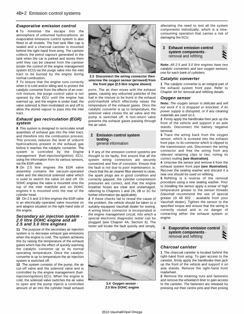
Evaporative emission control6 To minimise the escape into theatmosphere of unburned hydrocarbons, anevaporative emissions control system is alsofitted to all models. The fuel tank filler cap issealed and a charcoal canister is mountedbehind the right-hand front wing. The canistercollects the petrol vapours generated in thetank when the car is parked and stores themuntil they can be cleared from the canister(under the control of the engine managementsystem ECU) via the purge valve into the inlettract to be burned by the engine duringnormal combustion.7 To ensure that the engine runs correctlywhen it is cold and/or idling and to protect thecatalytic converter from the effects of an over-rich mixture, the purge control valve is notopened by the ECU until the engine haswarmed up, and the engine is under load; thevalve solenoid is then modulated on and off toallow the stored vapour to pass into the inlettract.
Exhaust gas recirculation (EGR)system8 This system is designed to recirculate smallquantities of exhaust gas into the inlet tract,and therefore into the combustion process.This process reduces the level of unburnthydrocarbons present in the exhaust gasbefore it reaches the catalytic converter. Thesystem is controlled by the Enginemanagement (fuel-injection/ignition) ECU,using the information from its various sensors,via the EGR valve.9 On 2.0 litre engines the EGR valveassembly contains the vacuum-operatedvalve and the electrical solenoid valve whichis used to switch the valve on and off. OnSOHC engines the valve is mounted onto thetop of the inlet manifold and on DOHCengines it is mounted onto the rear of thecylinder head.10 On 2.5 and 3.0 litre engines the EGR valveis an electrically-operated valve mounted onand adaptor situated on the right-hand side ofthe engine.
Secondary air injection system -2.0 litre DOHC engine and all2.5 and 3.0 litre engines11 The purpose of the secondary air injectionsystem is to decrease exhaust gas emissionswhen the engine is cold. The system achievesthis by raising the temperature of the exhaustgases which has the effect of quickly warmingthe catalytic converter up to its normaloperating temperature. Once the catalyticconverter is up to temperature the air injectionsystem is switched off.12 The system consists of the pump, the aircut-off valve and the solenoid valve and iscontrolled by the engine management (fuel-injection/ignition) ECU. When the engine iscold, the solenoid valve switches the air valveto open and the pump injects a controlledamount of air into the cylinder head exhaust
ports. The air then mixes with the exhaustgases, causing any unburned particles of thefuel in the mixture to be burnt in the exhaustport/manifold which effectively raises thetemperature of the exhaust gases. Once thecatalytic converter is up to temperature, thesolenoid valve closes the air valve and thepump is switched off. A non-return valveprevents the exhaust gases passing throughthe air valve.
2 Emission control systemtesting - general information
1 If any of the emission control systems arethought to be faulty, first ensure that all thesystem wiring connectors are securelyconnected and free of corrosion. Ensure thatthe fault is not due to poor maintenance; ie,check that the air cleaner filter element is clean,the spark plugs are in good condition andcorrectly gapped, the cylinder compressionpressures are correct, and that the enginebreather hoses are clear and undamaged,referring to Chapters 1 and 2A, 2B or 2C forfurther information (as applicable).2 If these checks fail to reveal the cause ofthe problem, the vehicle should be taken to asuitably-equipped Vauxhall dealer for testing.A wiring block connector is incorporated inthe engine management circuit, into which aspecial electronic diagnostic tester can beplugged (see Chapter 4A, Section 6). Thetester will locate the fault quickly and simply,
alleviating the need to test all the systemcomponents individually, which is a time-consuming operation that carries a risk ofdamaging the ECU.
3 Exhaust emission controlsystem components -removal and refitting
3Note: All 2.5 and 3.0 litre engines have twocatalytic converters and two oxygen sensors;one for each bank of cylinders.
Catalytic converter1 The catalytic converter is an integral part ofthe exhaust system front pipe. Refer toChapter 4A for removal and refitting details.
Oxygen sensorNote: The oxygen sensor is delicate and willnot work if it is dropped or knocked, if itspower supply is disrupted, or if any cleaningmaterials are used on it.2 Firmly apply the handbrake then jack up thefront of the vehicle and support it on axlestands. Disconnect the battery negativeterminal.3 Trace the wiring back from the oxygensensor, which is screwed into the exhaustfront pipe, to its connector which is clipped tothe transmission unit. Disconnect the wiringconnector and free the wiring from anyrelevant retaining clips or ties, noting itscorrect routing (see illustration).4 Unscrew the sensor and remove it from theexhaust system front pipe (see illustration).Recover the sealing washer and discard it anew one should be used on refitting.5 Refitting is a reverse of the removalprocedure using a new sealing washer. Priorto installing the sensor apply a smear of hightemperature grease to the sensor threads(Vauxhall recommend the use of specialgrease 19 48 602 - available from yourVauxhall dealer). Tighten the sensor to thespecified torque and ensure that the wiring iscorrectly routed and in no danger ofcontacting either the exhaust system orengine.
4 Evaporative emission controlsystem components -removal and refitting
3Charcoal canister1 The charcoal canister is located behind theright-hand front wing. To gain access to thecanister, firmly apply the handbrake then jackup the front of the vehicle and support it onaxle stands. Remove the right-hand frontroadwheel.2 Remove the retaining nuts and fastenersand remove the wheelarch liner to gain accessto the canister. The fasteners are released bypressing out their centre pins and then prising
4B•2 Emission control systems
3.4 Oxygen sensor - 2.0 litre DOHC engine
3.3 Disconnect the wiring connector thenunscrew the oxygen sensor (arrowed) from
the front pipe (2.5 litre engine shown)
3510 Vauxhall/Opel Omega

out the outer section; the centre pins must berecovered so they can be reused on refitting(see illustrations).3 Slacken and remove the retaining nut andfree the canister from its mounting. Mark thehoses for identification purposes thendisconnect them and remove the canisterfrom the vehicle (see illustrations).4 Refitting is a reverse of the removalprocedure ensuring the hoses are correctlyand securely reconnected.
Purge valve
2.0 litre SOHC engine5 The purge valve is mounted onto the top ofthe inlet manifold.6 Undo the bolts securing the wiring cover tothe camshaft housing and position the coverclear of the purge valve.7 To improve access to the valve, release theretaining clips and disconnect the breatherhoses from the camshaft housing.8 Ensure the ignition is switched off thendepress the retaining clip and disconnect thewiring connector from the valve.9 Slacken and remove the valve bracketupper screw then loosen the lower screw andfree the valve bracket from the engine.Disconnect the hoses from the valve, notingtheir correct fitted locations and remove thevalve from the engine. The valve and bracketcan then be separated.10 Refitting is a reversal of the removalprocedure ensuring the hoses are securelyconnected.
2.0 litre DOHC engine11 The purge valve is mounted on the rear ofthe cylinder head, on the right-hand side ofthe DIS module.12 Firmly apply the handbrake then jack upthe front of the vehicle and support it on axlestands. Access the valve can then be gainedfrom above and underneath.13 Ensure the ignition is switched off thendisconnect the wiring connector from thevalve.14 Release the retaining clip and free thewiring harness from the purge valve bracketthen undo the retaining screws and free thepurge valve bracket from the cylinder head.15 Disconnect the vacuum hoses, notingtheir correct fitted locations and remove thepurge valve and mounting bracket from thevehicle. The valve and bracket can then beseparated.16 Refitting is a reversal of the removalprocedure ensuring the hoses are securelyconnected.
2.5 and 3.0 litre engines17 The purge valve is located at the rear ofthe right-hand cylinder head.18 Remove the inlet manifold upper sectionas described in Chapter 4A. To furtherimprove access, remove the windscreenwiper arms and the water deflector panel fromthe base of the windscreen (see Chapter 12,Sections 15 and 16).19 Slacken and remove the valve bracketretaining bolt then, ensuring the ignition is
switched off, disconnect the wiring connectorfrom the valve (see illustration).20 Disconnect the vacuum hoses, notingtheir correct fitted locations and remove thepurge valve and mounting bracket from theengine. The valve and bracket can then beseparated.21 Refitting is a reversal of the removalprocedure ensuring the hoses are securelyconnected.
5 Exhaust gas recirculation(EGR) system components -removal and refitting
3EGR valve
2.0 litre SOHC engine1 On 2.0 litre SOHC engines, to improveaccess undo the bolts securing the wiringcover to the camshaft housing and positionthe cover clear of the EGR valve which ismounted onto the top of the inlet manifold.2 Ensure the ignition is switched off thendisconnect the wiring connector and vacuumhose from the valve.3 Undo the retaining screws and remove thevalve and its gasket, noting which way aroundthe valve is fitted.4 Refitting is the reverse of removal using anew gasket. Ensure the valve is fitted thecorrect way around and tighten its retainingbolts to the specified torque.
Emission control systems 4B•3
4B
4.2a Unscrew the retaining nuts thenpress out the centre pins . . .
4.2b . . . and remove the fastener outersections . . .
4.2c . . . and remove the right-hand frontwheelarch liner
4.3b . . . then free the charcoal canisterfrom its mounting and disconnect it from
its hoses
4.3a Unscrew the retaining nut . . .4.19 On 2.5 and 3.0 litre engines the purgevalve (arrowed) is mounted on the rear ofthe right-hand cylinder head (shown with
engine removed)
3510 Vauxhall/Opel Omega
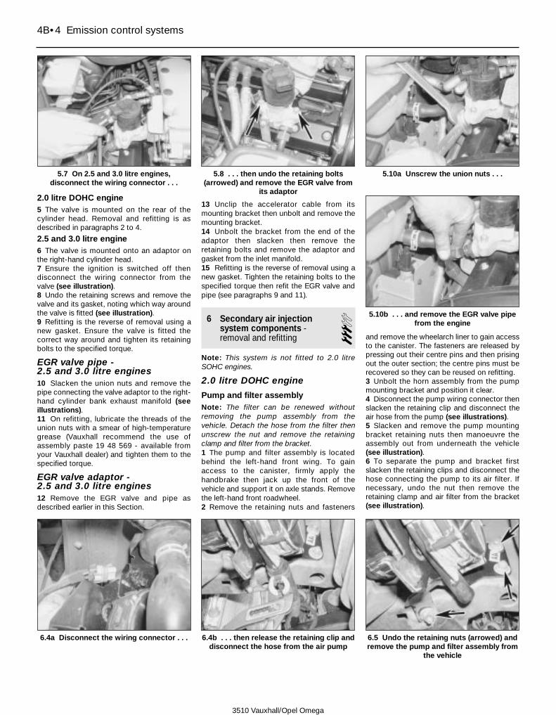
2.0 litre DOHC engine5 The valve is mounted on the rear of thecylinder head. Removal and refitting is asdescribed in paragraphs 2 to 4.
2.5 and 3.0 litre engine6 The valve is mounted onto an adaptor onthe right-hand cylinder head.7 Ensure the ignition is switched off thendisconnect the wiring connector from thevalve (see illustration).8 Undo the retaining screws and remove thevalve and its gasket, noting which way aroundthe valve is fitted (see illustration).9 Refitting is the reverse of removal using anew gasket. Ensure the valve is fitted thecorrect way around and tighten its retainingbolts to the specified torque.
EGR valve pipe - 2.5 and 3.0 litre engines10 Slacken the union nuts and remove thepipe connecting the valve adaptor to the right-hand cylinder bank exhaust manifold (seeillustrations).11 On refitting, lubricate the threads of theunion nuts with a smear of high-temperaturegrease (Vauxhall recommend the use ofassembly paste 19 48 569 - available fromyour Vauxhall dealer) and tighten them to thespecified torque.
EGR valve adaptor - 2.5 and 3.0 litre engines12 Remove the EGR valve and pipe asdescribed earlier in this Section.
13 Unclip the accelerator cable from itsmounting bracket then unbolt and remove themounting bracket.14 Unbolt the bracket from the end of theadaptor then slacken then remove theretaining bolts and remove the adaptor andgasket from the inlet manifold.15 Refitting is the reverse of removal using anew gasket. Tighten the retaining bolts to thespecified torque then refit the EGR valve andpipe (see paragraphs 9 and 11).
6 Secondary air injectionsystem components -removal and refitting 3
Note: This system is not fitted to 2.0 litreSOHC engines.
2.0 litre DOHC engine
Pump and filter assemblyNote: The filter can be renewed withoutremoving the pump assembly from thevehicle. Detach the hose from the filter thenunscrew the nut and remove the retainingclamp and filter from the bracket.1 The pump and filter assembly is locatedbehind the left-hand front wing. To gainaccess to the canister, firmly apply thehandbrake then jack up the front of thevehicle and support it on axle stands. Removethe left-hand front roadwheel.2 Remove the retaining nuts and fasteners
and remove the wheelarch liner to gain accessto the canister. The fasteners are released bypressing out their centre pins and then prisingout the outer section; the centre pins must berecovered so they can be reused on refitting.3 Unbolt the horn assembly from the pumpmounting bracket and position it clear.4 Disconnect the pump wiring connector thenslacken the retaining clip and disconnect theair hose from the pump (see illustrations).5 Slacken and remove the pump mountingbracket retaining nuts then manoeuvre theassembly out from underneath the vehicle(see illustration).6 To separate the pump and bracket firstslacken the retaining clips and disconnect thehose connecting the pump to its air filter. Ifnecessary, undo the nut then remove theretaining clamp and air filter from the bracket(see illustration).
4B•4 Emission control systems
5.7 On 2.5 and 3.0 litre engines,disconnect the wiring connector . . .
5.8 . . . then undo the retaining bolts(arrowed) and remove the EGR valve from
its adaptor
5.10a Unscrew the union nuts . . .
5.10b . . . and remove the EGR valve pipefrom the engine
6.4b . . . then release the retaining clip anddisconnect the hose from the air pump
6.4a Disconnect the wiring connector . . . 6.5 Undo the retaining nuts (arrowed) andremove the pump and filter assembly from
the vehicle
3510 Vauxhall/Opel Omega

7 Make alignment marks between the pump,bracket, mounting plate and rubber then freethe pump wiring connector from the bracket.8 Undo the retaining bolts and remove thepump from its mounting bracket. If necessary,unscrew the retaining nuts and remove the
mounting plate and rubber from the bracket(see illustrations).9 Refitting is the reverse of removal aligningthe marks made prior to removal and tightenthe mounting nuts and bolts to their specifiedtorque settings.
Cut-off valve10 The valve is located on the left-hand sideof the engine compartment. Disconnect thevacuum pipe from the valve then release theretaining clips and disconnect the air hoses(see illustration).11 Slacken and remove the retaining boltsand remove the valve from the vehicle, notingwhich way around it is fitted.12 Refitting is the reverse of removal makingsure the valve is fitted the correct way around;the arrow on the valve must point in thedirection of air flow (towards the engine).
Cut-off valve solenoid13 The solenoid valve is located next to thecut-off valve on the left-hand side of theengine compartment (see illustration).14 Ensure the ignition is switched off thendisconnect the wiring connector from thevalve and detach the vacuum hoses, notingeach ones correct fitted location.
Emission control systems 4B•5
4B
6.8c If necessary, undo the retaining nuts(arrowed) and remove the mounting plate
and rubber from the bracket
6.8b . . . and separate the pump from itsmounting bracket
3510 Vauxhall/Opel Omega
6.6 Release the retaining clip (A) and disconnect the hose thenundo the retaining nut (B) and remove the clamp and filter assembly
6.8a Undo the retaining bolts (arrowed) . . .
6.10 On 2.0 litre DOHC engines disconnect the vacuum hose (1)then release the retaining clips and free the air hoses (2) from the
cut-off valve
6.13 Disconnect the wiring connector (1) and vacuum hoses (2)from the cut-off valve solenoid

15 Undo the retaining screws and removethe valve from the engine compartment.16 Refitting is the reverse of removal ensuringthe vacuum hoses are correctly reconnected.
Non-return valve17 The non-return valve is located on the topof the exhaust manifold.18 Release the retaining clip and disconnectthe air hose from the pipe then unscrew thevalve and remove it from the connecting pipe(see illustration).19 On refitting, clean the valve threads andapply a smear of fresh sealing compound tothem (Vauxhall recommend the use of sealingcompound 15 03 295 - available from yourVauxhall dealer). Refit the valve to its pipe andtighten it to the specified torque beforesecurely reconnecting the air hose.
Connecting pipe20 Release the retaining clip and disconnectthe air hose from the connecting pipe non-return valve.21 Slacken and remove the retaining boltsand remove the bracket securing theconnecting pipe to the exhaust manifold.22 Undo the retaining bolts and remove theheatshield from the exhaust manifold.23 Slacken the retaining clip and disconnect
the breather hose from the left-hand side ofthe cylinder head cover.24 Undo the retaining bolts and remove theconnecting pipe from the cylinder head/manifold. Recover the gaskets which are fittedbetween the pipe unions and cylinder headand discard them.25 Refitting is the reverse of removal, notingthe following.a) Ensure the mating surfaces are clean and
dry and use new gaskets.b) Apply a smear of high-temperature grease
(Vauxhall recommend the use of assemblypaste 19 48 569 - available from yourVauxhall dealer) to the threads of the piperetaining bolts and heatshield bolts priorto refitting.
c) Tighten all bolts to their specified torquesettings (where given).
2.5 and 3.0 litre engines
Pump and filter assembly26 Refer to paragraphs 1 to 9.
Cut-off valve and solenoid valve27 The cut-off valve and its solenoid aremounted onto a bracket which is secured tothe rear of the radiator.28 Disconnect the vacuum pipe from the
solenoid valve then release the retaining clipsand disconnect the air hoses from the cut-offvalve (see illustrations).29 Slacken and remove the retaining boltssecuring the valve mounting bracket to theradiator and remove the bracket assemblyfrom the vehicle, disconnecting the valvewiring connector as it becomes accessible(see illustration).30 Undo the retaining bolts and remove thecut-off valve/solenoid valve (as applicable)from the bracket, noting which way around itis fitted (see illustration).31 Refitting is the reverse of removal. If thecut-off valve has been removed, make sure itis fitted the correct way around with the arrowpointing in the direction of air flow (towardsthe engine).
Non-return valve32 The non-return valve is screwed onto theleft-hand end of the front connecting pipe andis located just in front of the timing belt cover(see illustration). To improve access to thevalve unbolt the air conditioning pipe/hosebracket from the cylinder head and positionthe hose/pipe to one side.33 Release the retaining clip and disconnectthe air hose from the pipe then unscrew thevalve and remove it from its pipe.
4B•6 Emission control systems
6.18 Release the retaining clip anddisconnect the air hose from the non-
return valve (arrowed)
6.28a Disconnect the vacuum pipe fromthe solenoid valve . . .
6.28b . . . then release the retaining clipsand disconnect the hoses from the cut-off
valve
3510 Vauxhall/Opel Omega
6.29 Undo the retaining bolts and disconnect the wiringconnector (arrowed) then remove the bracket assembly from the
vehicle6.30 Air cut-off valve (A) and solenoid valve (B) can then be
unbolted from the bracket

34 On refitting, clean the valve threads andapply a smear of fresh sealing compound tothem (Vauxhall recommend the use of sealingcompound 15 03 295 - available from yourVauxhall dealer). Refit the valve to its pipe andtighten it to the specified torque beforesecurely reconnecting the air hose.
Front connecting pipe35 Remove the multi-ram air intake system pre-volume chamber as described in Chapter 4A.36 Release the retaining clip and disconnectthe air hose from the front connecting pipenon-return valve (see illustration).37 Unscrew the pipe retaining nuts thenrelease the retaining clips securing the pipeends to the hoses and remove the assemblyfrom the engine compartment. If necessary,slacken the alternator upper mounting nut andpivot the pipe bracket out of position to gainthe necessary clearance required for removal(see illustrations).38 Refitting is the reverse of removalensuring the hose are correctly and securelyreconnected.
Left-hand cylinder head connectingpipe39 Remove the exhaust system left-handfront pipe as described in Chapter 4A.40 On models with air conditioning, remove
the auxiliary drivebelt then unbolt thecompressor and position it clear of itsmounting bracket (see Chapters 1 and 3).
Warning: Do not disconnect anyof the refrigerant pipes/hoses
41 Slacken and remove the bolts securingthe upper and lower heatshields to the left-hand exhaust manifold. Remove the lowerheatshield and position the upper one clear ofthe manifold so access can be gained to theconnecting pipe bolts.42 Slacken and remove the retaining bolts
and free the connecting pipe from themanifold (see illustration). Release theretaining clip securing the rubber hose to thefront of the connecting pipe then disconnectthe pipe and manoeuvre it out fromunderneath the vehicle. Recover the gasketswhich are fitted between the pipe andmanifold and discard them.43 Refitting is the reverse of removal, notingthe following points.a) Ensure the mating surfaces are clean and
dry and use new gaskets (seeillustration).
Emission control systems 4B•7
4B
6.32 Non return valve location - 2.5 and 3.0 litre engines
6.36 Disconnect the air hose from the non-return valve on the front connecting pipe
6.37a Slacken and remove the left-hand . . .
6.42 Removing the left-hand connectingpipe from the manifold (shown with engine
removed)
6.43 On refitting, ensure the matingsurfaces are clean and dry and fit new
gaskets to the connecting pipe
3510 Vauxhall/Opel Omega
6.37b . . . and right-hand retaining nuts then (if necessary)slacken the alternator mounting nut and pivot the bracket
(arrowed) clear of the pipe . . .6.37c . . . to allow the front connecting pipe to be removed from
the engine

b) Apply a smear of high-temperature grease(Vauxhall recommend the use of assemblypaste 19 48 569 - available from yourVauxhall dealer) to the threads of the piperetaining bolts and the heatshield boltsprior to refitting.
c) Tighten all bolts to their specified torquesettings (where given).
Right-hand cylinder head connectingpipe44 Slacken and remove the bolt securing thecoolant pipe bracket to the right-handcylinder head.45 Slacken and remove the retaining boltsthen remove the lower and upper heatshieldsfrom the exhaust manifold (see illustrations).46 Taking care not to place excess strain onthe coolant pipe, slacken and remove theretaining bolts securing the connecting pipeto the manifold.47 Free the connecting pipe from themanifold then release the retaining clipsecuring the rubber hose to the front of theconnecting pipe then disconnect the pipe andmanoeuvre it out of position (see illustration).Recover the gaskets which are fitted betweenthe pipe and manifold and discard them.48 Refitting is the reverse of removal, notingthe following points.a) Ensure the mating surfaces are clean and
dry and use new gaskets.b) Apply a smear of high-temperature grease
(Vauxhall recommend the use of assemblypaste 19 48 569 - available from yourVauxhall dealer) to the threads of the piperetaining bolts and heatshield bolts priorto refitting.
c) Tighten all bolts to their specified torquesettings (where given).
7 Catalytic converter - general information and precautions
1 The catalytic converter is a reliable andsimple device which needs no maintenance initself, but there are some facts of which anowner should be aware if the converter is tofunction properly for its full service life.a) DO NOT use leaded petrol in a car
equipped with a catalytic converter - thelead will coat the precious metals,reducing their converting efficiency andwill eventually destroy the converter.
b) Always keep the ignition and fuel systemswell-maintained in accordance with themanufacturer’s schedule.
c) If the engine develops a misfire, do notdrive the car at all (or at least as little aspossible) until the fault is cured.
d) DO NOT push- or tow-start the car - thiswill soak the catalytic converter inunburned fuel, causing it to overheatwhen the engine does start.
e) DO NOT switch off the ignition at highengine speeds.
f) DO NOT use fuel or engine oil additives -these may contain substances harmful tothe catalytic converter.
g) DO NOT continue to use the car if theengine burns oil to the extent of leaving avisible trail of blue smoke.
h) Remember that the catalytic converteroperates at very high temperatures. DONOT, therefore, park the car in dryundergrowth, over long grass or piles ofdead leaves after a long run.
i) Remember that the catalytic converter isFRAGILE - do not strike it with toolsduring servicing work.
j) In some cases a sulphurous smell (likethat of rotten eggs) may be noticed fromthe exhaust. This is common to manycatalytic converter-equipped cars andonce the car has covered a few thousandmiles the problem should disappear.
k) The catalytic converter, used on a well-maintained and well-driven car, shouldlast indefinitely - if the converter is nolonger effective it must be renewed.
4B•8 Emission control systems
6.45a Undo the retaining bolts and removethe lower . . .
6.45b . . . and upper heatshields from theright-hand exhaust manifold (shown with
engine removed)
6.47 Removing the right-hand connectingpipe from the manifold
3510 Vauxhall/Opel Omega

3510 Vauxhall/Opel Omega
5A•1
5A
Chapter 5 Part A:Starting and charging systems
System type . . . . . . . . . . . . . . . . . . . . . . . . . . . . . . . . . . . . . . . . . . . 12-volt, negative earth
BatteryCharge condition:
Poor . . . . . . . . . . . . . . . . . . . . . . . . . . . . . . . . . . . . . . . . . . . . . . . . . . 12.5 voltsNormal . . . . . . . . . . . . . . . . . . . . . . . . . . . . . . . . . . . . . . . . . . . . . . . . 12.6 voltsGood . . . . . . . . . . . . . . . . . . . . . . . . . . . . . . . . . . . . . . . . . . . . . . . . . . 12.7 volts
Torque wrench settings Nm lbf ftAlternator mounting bolts:
2.0 litre engine:Lower bolt . . . . . . . . . . . . . . . . . . . . . . . . . . . . . . . . . . . . . . . . . . . . 35 26Upper bracket bolts:
SOHC engine . . . . . . . . . . . . . . . . . . . . . . . . . . . . . . . . . . . . . . . 18 13DOHC engine . . . . . . . . . . . . . . . . . . . . . . . . . . . . . . . . . . . . . . . 20 15
2.5 and 3.0 litre engine . . . . . . . . . . . . . . . . . . . . . . . . . . . . . . . . . . . . 35 26Oil level sensor bolts . . . . . . . . . . . . . . . . . . . . . . . . . . . . . . . . . . . . . . . . 8 6Oil pressure switch . . . . . . . . . . . . . . . . . . . . . . . . . . . . . . . . . . . . . . . . . 40 30Starter motor bolts:
2.0 litre engine:Lower bolt . . . . . . . . . . . . . . . . . . . . . . . . . . . . . . . . . . . . . . . . . . . . 45 33Rear mounting bracket to block bolt . . . . . . . . . . . . . . . . . . . . . . . 25 18Upper bolt . . . . . . . . . . . . . . . . . . . . . . . . . . . . . . . . . . . . . . . . . . . . 60 44
2.5 and 3.0 litre engine . . . . . . . . . . . . . . . . . . . . . . . . . . . . . . . . . . . . 40 30
Alternator - removal and refitting . . . . . . . . . . . . . . . . . . . . . . . . . . . . 7Alternator - testing and overhaul . . . . . . . . . . . . . . . . . . . . . . . . . . . . 8Alternator drivebelt - removal, refitting and tensioning . . . . . . . . . . . 6Battery - removal and refitting . . . . . . . . . . . . . . . . . . . . . . . . . . . . . . 4Battery - testing and charging . . . . . . . . . . . . . . . . . . . . . . . . . . . . . . 3Battery check . . . . . . . . . . . . . . . . . . . . . . . . . . . . . .See Weekly checksCharging system - testing . . . . . . . . . . . . . . . . . . . . . . . . . . . . . . . . . 5Electrical fault finding - general information . . . . . . . . . . . . . . . . . . . 2
General information and precautions . . . . . . . . . . . . . . . . . . . . . . . . 1Ignition switch - removal and refitting . . . . . . . . . . . . . . . . . . . . . . . . 12Oil level sensor - removal and refitting . . . . . . . . . . . . . . . . . . . . . . . 14Oil pressure warning light switch - removal and refitting . . . . . . . . . 13Starter motor - removal and refitting . . . . . . . . . . . . . . . . . . . . . . . . . 10Starter motor - testing and overhaul . . . . . . . . . . . . . . . . . . . . . . . . . 11Starting system - testing . . . . . . . . . . . . . . . . . . . . . . . . . . . . . . . . . . 9
Specifications
Contents
Easy, suitable fornovice with littleexperience
Fairly easy, suitablefor beginner withsome experience
Fairly difficult,suitable for competentDIY mechanic
Difficult, suitable forexperienced DIYmechanic
Very difficult,suitable for expert DIYor professional
Degrees of difficulty
54321
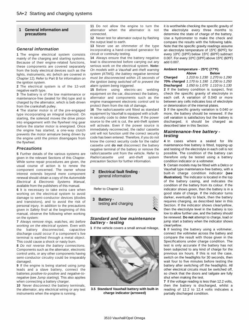
1 General information andprecautions
General information1 The engine electrical system consistsmainly of the charging and starting systems.Because of their engine-related functions,these components are covered separatelyfrom the body electrical devices such as thelights, instruments, etc (which are covered inChapter 12). Refer to Part B for information onthe ignition system.2 The electrical system is of the 12-voltnegative earth type.3 The battery is of the low maintenance ormaintenance-free (sealed for life) type and ischarged by the alternator, which is belt-drivenfrom the crankshaft pulley.4 The starter motor is of the pre-engagedtype incorporating an integral solenoid. Onstarting, the solenoid moves the drive pinioninto engagement with the flywheel ring gearbefore the starter motor is energised. Oncethe engine has started, a one-way clutchprevents the motor armature being driven bythe engine until the pinion disengages fromthe flywheel.
Precautions5 Further details of the various systems aregiven in the relevant Sections of this Chapter.While some repair procedures are given, theusual course of action is to renew thecomponent concerned. The owner whoseinterest extends beyond mere componentrenewal should obtain a copy of the AutomobileElectrical & Electronic Systems Manual,available from the publishers of this manual.6 It is necessary to take extra care whenworking on the electrical system to avoiddamage to semi-conductor devices (diodesand transistors), and to avoid the risk ofpersonal injury. In addition to the precautionsgiven in Safety first! at the beginning of thismanual, observe the following when workingon the system:7 Always remove rings, watches, etc beforeworking on the electrical system. Even withthe battery disconnected, capacitivedischarge could occur if a component’s liveterminal is earthed through a metal object.This could cause a shock or nasty burn.8 Do not reverse the battery connections.Components such as the alternator, electroniccontrol units, or any other components havingsemi-conductor circuitry could be irreparablydamaged.9 If the engine is being started using jumpleads and a slave battery, connect thebatteries positive-to-positive and negative-to-negative (see Jump starting). This also applieswhen connecting a battery charger.10 Never disconnect the battery terminals,the alternator, any electrical wiring or any testinstruments when the engine is running.
11 Do not allow the engine to turn thealternator when the alternator is notconnected.12 Never test for alternator output by flashingthe output lead to earth.13 Never use an ohmmeter of the typeincorporating a hand-cranked generator forcircuit or continuity testing.14 Always ensure that the battery negativelead is disconnected before carrying out anyserious work on the electrical system. Note:On models with a Vauxhall anti-theft warningsystem (ATWS), the battery negative terminalmust be disconnected within 15 seconds ofthe ignition being switched off to prevent thealarm system being triggered.15 Before using electric-arc weldingequipment on the car, disconnect the battery,alternator and components such as theengine management electronic control unit toprotect them from the risk of damage.16 The radio/cassette unit fitted as standardequipment by Vauxhall is equipped with a built-in security code to deter thieves. If the powersource to the unit is cut, the anti-theft systemwill activate. Even if the power source isimmediately reconnected, the radio/ cassetteunit will not function until the correct securitycode has been entered. Therefore, if you do notknow the correct security code for the radio/cassette unit do not disconnect the batterynegative terminal of the battery or remove theradio/cassette unit from the vehicle. Refer toRadio/cassette unit anti-theft systemprecaution Section for further information.
2 Electrical fault finding -general information
Refer to Chapter 12.
3 Battery - testing and charging 1
Standard and low maintenancebattery - testing1 If the vehicle covers a small annual mileage,
it is worthwhile checking the specific gravity ofthe electrolyte every three months todetermine the state of charge of the battery.Use a hydrometer to make the check andcompare the results with the following table.Note that the specific gravity readings assumean electrolyte temperature of 15ºC (60ºF); forevery 10ºC (18ºF) below 15ºC (60ºF) subtract0.007. For every 10ºC (18ºF) above 15ºC (60ºF)add 0.007.
Ambient temperature - 25ºC (77ºF)Above Below
Charged 1.210 to 1.230 1.270 to 1.29070% charged 1.170 to 1.190 1.230 to 1.250Discharged 1.050 to 1.070 1.110 to 1.1302 If the battery condition is suspect, firstcheck the specific gravity of electrolyte ineach cell. A variation of 0.040 or morebetween any cells indicates loss of electrolyteor deterioration of the internal plates.3 If the specific gravity variation is 0.040 ormore, the battery should be renewed. If thecell variation is satisfactory but the battery isdischarged, it should be charged asdescribed later in this Section.
Maintenance-free battery -testing4 In cases where a sealed for lifemaintenance-free battery is fitted, topping-upand testing of the electrolyte in each cell is notpossible. The condition of the battery cantherefore only be tested using a batterycondition indicator or a voltmeter.5 Certain models may be fitted with a Delco orVauxhall type maintenance-free battery, with abuilt-in charge condition indicator (seeillustration). The indicator is located in the topof the battery casing, and indicates thecondition of the battery from its colour. If theindicator shows green, then the battery is in agood state of charge. If the indicator turnsdarker, eventually to black, then the batteryrequires charging, as described later in thisSection. If the indicator shows clear/yellow,then the electrolyte level in the battery is toolow to allow further use, and the battery shouldbe renewed. Do not attempt to charge, load orjump start a battery when the indicator showsclear/yellow.6 If testing the battery using a voltmeter,connect the voltmeter across the battery andcompare the result with those given in theSpecifications under charge condition. Thetest is only accurate if the battery has notbeen subjected to any kind of charge for theprevious six hours. If this is not the case,switch on the headlights for 30 seconds, thenwait four to five minutes before testing thebattery after switching off the headlights. Allother electrical circuits must be switched off,so check that the doors and tailgate are fullyshut when making the test.7 If the voltage reading is less than 12.2 volts,then the battery is discharged, whilst areading of 12.2 to 12.4 volts indicates apartially discharged condition.
5A•2 Starting and charging systems
3.5 Standard Vauxhall battery with built-incharge indicator (arrowed)
3510 Vauxhall/Opel Omega

8 If the battery is to be charged, remove itfrom the vehicle (Section 4) and charge it asdescribed later in this Section.
Standard and low maintenancebattery - chargingNote: The following is intended as a guideonly. Always refer to the manufacturer’srecommendations (often printed on a labelattached to the battery) before charging abattery.9 Charge the battery at a rate of 3.5 to 4amps and continue to charge the battery atthis rate until no further rise in specific gravityis noted over a four hour period.10 Alternatively, a trickle charger charging atthe rate of 1.5 amps can safely be usedovernight.11 Specially rapid boost charges which areclaimed to restore the power of the battery in 1to 2 hours are not recommended, as they cancause serious damage to the battery platesthrough overheating.12 While charging the battery, note that thetemperature of the electrolyte should neverexceed 37.8ºC (100ºF).
Maintenance-free battery -chargingNote: The following is intended as a guideonly. Always refer to the manufacturer’srecommendations (often printed on a labelattached to the battery) before charging abattery.13 This battery type takes considerablylonger to fully recharge than the standardtype, the time taken being dependent on theextent of discharge, but it can take anythingup to three days.14 A constant voltage type charger isrequired, to be set, when connected, to 13.9to 14.9 volts with a charger current below 25amps. Using this method, the battery shouldbe usable within three hours, giving a voltagereading of 12.5 volts, but this is for a partiallydischarged battery and, as mentioned, fullcharging can take considerably longer.15 If the battery is to be charged from a fullydischarged state (condition reading less than12.2 volts), have it recharged by your Vauxhalldealer or local automotive electrician, as thecharge rate is higher and constant supervisionduring charging is necessary.
4 Battery - removal and refitting 1
Note: If a Vauxhall radio/cassette unit is fitted,refer to Radio/cassette unit anti-theft system -precaution.
Removal1 The battery is located on the left-hand sideof the engine compartment. On some modelsthe battery will be housed in a protectivecasing.
2 Unclip the cover (where fitted) then slackenthe clamp nut and disconnect the clamp fromthe battery negative (earth) terminal. Note: Onmodels with a Vauxhall anti-theft warningsystem (ATWS), the battery negative terminalmust be disconnected within 15 seconds ofthe ignition being switched off to prevent thealarm system being triggered.3 On models where a fusible link housing isclipped onto the engine compartment relaybox, unclip the housing and position it clear ofthe battery (see illustration).4 Lift the insulation cover and disconnect thepositive terminal lead in the same way.5 Unscrew the bolt and remove the batteryretaining clamp and lift the battery out of theengine compartment.
Refitting6 Refitting is a reversal of removal, but smearpetroleum jelly on the terminals when recon-necting the leads, and always reconnect thepositive lead first, and the negative lead last.
5 Charging system - testing 2
Note: Refer to the warnings given in Safetyfirst! and in Section 1 of this Chapter beforestarting work.1 If the ignition warning light fails to illuminatewhen the ignition is switched on, first check
the alternator wiring connections for security.If satisfactory, check that the warning lightbulb has not blown, and that the bulbholder issecure in its location in the instrument panel.If the light still fails to illuminate, check thecontinuity of the warning light feed wire fromthe alternator to the bulbholder. If all issatisfactory, the alternator is at fault andshould be renewed or taken to an auto-electrician for testing and repair.2 If the ignition warning light illuminates whenthe engine is running, stop the engine andcheck that the drivebelt is correctly tensioned(see Section 6) and that the alternatorconnections are secure. If all is so farsatisfactory, have the alternator checked byan auto-electrician for testing and repair.3 If the alternator output is suspect eventhough the warning light functions correctly,the regulated voltage may be checked asfollows.4 Connect a voltmeter across the batteryterminals and start the engine.5 Increase the engine speed until thevoltmeter reading remains steady; the readingshould be approximately 12 to 13 volts, andno more than 14 volts.6 Switch on as many electrical accessories(eg, the headlights, heated rear window andheater blower) as possible, and check that thealternator maintains the regulated voltage ataround 13 to 14 volts.7 If the regulated voltage is not as stated, thefault may be due to worn brushes, weak brushsprings, a faulty voltage regulator, a faultydiode, a severed phase winding or worn ordamaged slip rings. The alternator should berenewed or taken to an auto-electrician fortesting and repair.
6 Alternator drivebelt -removal, refitting andtensioning
1 Refer to the procedure given for theauxiliary drivebelt in Chapter 1.
7 Alternator - removal and refitting 3
Removal1 Disconnect the battery negative lead andproceed as described under the relevant sub-heading. Note: On models with a Vauxhallanti-theft warning system (ATWS), the batterynegative terminal must be disconnected within15 seconds of the ignition being switched offto prevent the alarm system being triggered.
2.0 litre engine2 Disconnect the wiring connectors from theintake air temperature sensor and the airflowmeter (see illustration).
Starting and charging systems 5A•3
5A
4.3 Where necessary, unclip the fusiblelink housing from the relay box and
position it clear of the battery
7.2 On 2.0 litre DOHC engines, disconnectthe wiring connector from the intake air
temperature sensor and airflow meter . . .
3510 Vauxhall/Opel Omega

3 Slacken the retaining clips then disconnectthe intake duct from the air cleaner andthrottle housing and remove the ductassembly from the engine compartment. OnDOHC engines it will be necessary todisconnect the breather hose in order to allowthe duct to be removed (see illustrations).4 Release the auxiliary drivebelt as describedin Chapter 1 and disengage it from thealternator pulley.5 Undo the bolts and remove the supportbrackets securing the alternator to the inletmanifold and cylinder head. Slacken the lowermounting bolt and pivot the alternator awayfrom the block to improve access to the wiringconnections.6 Remove the rubber covers (where fitted)from the alternator terminals, then unscrewthe retaining nuts and disconnect the wiringfrom the rear of the alternator.7 Unscrew the nut from the lower mountingbolt then withdraw the bolt and manoeuvrethe alternator out of position.
2.5 and 3.0 litre engines8 Firmly apply the handbrake then jack up thefront of the vehicle and support it on axlestands. Undo the retaining screws andremove the undercover from beneath theengine so access to the alternator can begained from below.9 Release the auxiliary drivebelt as describedin Chapter 1 and disengage it from thealternator pulley.10 Remove the rubber covers (where fitted)from the alternator terminals, then unscrewthe retaining nuts and disconnect the wiringfrom the rear of the alternator (seeillustration).11 Slacken and remove the upper and lowermounting nut and bolt then manoeuvre thealternator out of position.
Refitting12 Refitting is the reverse of removaltightening all mounting bolts to their specifiedtorque settings (where given). Ensure the
drivebelt is correctly refitted and tensioned asdescribed in Chapter 1.
8 Alternator - testing and overhaul 5
1 If the alternator is thought to be suspect, itshould be removed from the vehicle and takento an auto-electrician for testing. Most auto-electricians will be able to supply and fitbrushes at a reasonable cost. However, checkon the cost of repairs before proceeding as itmay prove more economical to obtain a newor exchange alternator.
9 Starting system - testing 3
Note: Refer to the precautions given in Safetyfirst! and in Section 1 of this Chapter beforestarting work.1 If the starter motor fails to operate when theignition key is turned to the appropriateposition, the following possible causes maybe to blame.
a) The battery is faulty.b) The electrical connections between the
switch, solenoid, battery and startermotor are somewhere failing to pass thenecessary current from the batterythrough the starter to earth.
c) The solenoid is faulty.d) The starter motor is mechanically or
electrically defective.2 To check the battery, switch on theheadlights. If they dim after a few seconds,this indicates that the battery is discharged -recharge (see Section 3) or renew the battery.If the headlights glow brightly, operate theignition switch and observe the lights. If theydim, then this indicates that current isreaching the starter motor, therefore the faultmust lie in the starter motor. If the lightscontinue to glow brightly (and no clickingsound can be heard from the starter motorsolenoid), this indicates that there is a fault inthe circuit or solenoid - see followingparagraphs. If the starter motor turns slowlywhen operated, but the battery is in goodcondition, then this indicates that either thestarter motor is faulty, or there is considerableresistance somewhere in the circuit.3 If a fault in the circuit is suspected,disconnect the battery leads (including theearth connection to the body), thestarter/solenoid wiring and theengine/transmission earth strap. Thoroughlyclean the connections, and reconnect theleads and wiring, then use a voltmeter or testlamp to check that full battery voltage isavailable at the battery positive leadconnection to the solenoid, and that the earthis sound. Smear petroleum jelly around thebattery terminals to prevent corrosion -corroded connections are amongst the mostfrequent causes of electrical system faults.4 If the battery and all connections are ingood condition, check the circuit bydisconnecting the wire from the solenoidblade terminal. Connect a voltmeter or testlamp between the wire end and a good earth
5A•4 Starting and charging systems
3510 Vauxhall/Opel Omega
7.3a . . . then disconnect the breather hose from the camshaftcover . . .
7.3b . . . before slackening the retaining clips and removing theintake duct assembly
7.10 Slacken the retaining nuts (arrowed)and disconnect the wiring from the rear of
the alternator (shown with engineremoved)

(such as the battery negative terminal), andcheck that the wire is live when the ignitionswitch is turned to the start position. If it is,then the circuit is sound - if not the circuitwiring can be checked as described inChapter 12, Section 2.5 The solenoid contacts can be checked byconnecting a voltmeter or test lamp betweenthe battery positive feed connection on thestarter side of the solenoid, and earth. When theignition switch is turned to the start position,there should be a reading or lighted bulb, asapplicable. If there is no reading or lighted bulb,the solenoid is faulty and should be renewed.6 If the circuit and solenoid are provedsound, the fault must lie in the starter motor.In this event, it may be possible to have thestarter motor overhauled by a specialist, butcheck on the cost of spares beforeproceeding, as it may prove more economicalto obtain a new or exchange motor.
10 Starter motor - removal and refitting 4
Removal1 Disconnect the battery negative lead thenfirmly apply the handbrake then jack up thefront of the vehicle and support it on axlestands. Undo the retaining screws andremove the undercover from beneath theengine then proceed as described under therelevant sub-heading. Note: On models with aVauxhall anti-theft warning system (ATWS),the battery negative terminal must bedisconnected within 15 seconds of theignition being switched off to prevent thealarm system being triggered.
2.0 litre engine2 Slacken and remove the two retaining nutsand disconnect the wiring from the startermotor solenoid. Recover the washers underthe nuts. On DOHC engine models, to improveaccess to the motor, undo the retaining boltsand remove the inlet manifold support bracket.3 Unscrew the retaining bolt securing thestarter motor rear bracket to the cylinderblock.4 Slacken and remove the upper and lowerretaining bolts, noting the bolts are differentlengths, and remove the starter motor fromthe vehicle. The upper bolt comes throughfrom behind and secures the transmission unitto the cylinder block.
2.5 and 3.0 litre engine5 Remove the right-hand engine mountingand bracket as described in Chapter 2C.6 Slacken and remove the two retaining nutsand disconnect the wiring from the startermotor solenoid. Recover the washers underthe nuts.7 Slacken and remove the upper and lowerretaining bolts and remove the starter motorfrom the vehicle.
Refitting8 Refitting is a reversal of removal tighteningthe retaining bolts to the specified torque.Ensure all wiring is correctly routed and itsretaining nuts are securely tightened.
11 Starter motor - testing and overhaul 5
1 If the starter motor is thought to be suspect,it should be removed from the vehicle andtaken to an auto-electrician for testing. Mostauto-electricians will be able to supply and fitbrushes at a reasonable cost. However, checkon the cost of repairs before proceeding as itmay prove more economical to obtain a newor exchange motor.
12 Ignition switch - removal and refitting
1 The ignition switch is integral with thesteering column lock, and can be removed asdescribed in Chapter 10.
13 Oil pressure warning light switch -removal and refitting 2
Removal1 The switch is screwed into the oil pumphousing which is located on the front of theengine, on the end of the crankshaft. On 2.0litre engines the switched is screwed into therear of the housing and on 2.5 and 3.0 litreengines it is screwed into the front of thehousing.2 To improve access to the switch, firmlyapply the handbrake then jacked up the frontof the vehicle and support it on axle stands.Undo the retaining bolts and remove theundercover from beneath the engine unit.3 Disconnect the wiring connector thenunscrew the switch and recover the sealingwasher. Be prepared for oil spillage, and if theswitch is to be left removed from the enginefor any length of time, plug the switchaperture.
Refitting4 Examine the sealing washer for signs ofdamage or deterioration and if necessaryrenew.5 Refit the switch and washer, tightening it tothe specified torque, and reconnect the wiringconnector.6 Refit the undercover then lower the vehicleto the ground. Check and, if necessary, topup the engine oil as described in Weeklychecks.
14 Oil level sensor - removal and refitting 3
2.0 litre SOHC engineRemoval1 The oil level sensor (where fitted) is locatedon the right-hand face of the engine sump.2 To gain access to the sensor, firmly applythe handbrake then jack up the front of thevehicle and support it on axle stands. Wherenecessary, undo the retaining screws andremove the undercover from beneath theengine unit.3 Drain the engine oil into a clean containerthen refit the drain plug and tighten it to thespecified torque setting (see Chapter 1).4 Disconnect the wiring connector from thesensor.5 Unscrew the retaining bolts then ease thesensor out from the sump and remove it alongwith its sealing ring. Discard the sealing ring, anew one should be used on refitting.
Refitting6 Refitting is the reverse of removal using anew sealing ring. On completion refill theengine with oil (see Chapter 1).
2.0 litre DOHC engineEngines with a one-piece sump7 Remove and refit the sensor as describedin paragraphs 1 to 6.
Engines with a two-piece sump8 Remove and refit the sensor as describedin paragraphs 9 to 11.
2.5 and 3.0 litre engineRemoval9 Remove the sump pan as described inChapter 2C.10 Unscrew the retaining bolts and removethe sensor from the sump pan, noting whichway around it is fitted (see illustration).
Refitting11 Ensure the sensor is correctly positionedthen tighten its retaining bolts to the specifiedtorque. Refit the sump pan as described inChapter 2C.
Starting and charging systems 5A•5
5A
3510 Vauxhall/Opel Omega
14.10 Removing the oil level sensor (2.5 litre engine shown)

3510 Vauxhall/Opel Omega
5B•1
5B
Chapter 5 Part B:Ignition system
System type . . . . . . . . . . . . . . . . . . . . . . . . . . . . . . . . . . . . . . . . . . . Distributorless ignition system controlled by engine management ECU
Firing order2.0 litre engine . . . . . . . . . . . . . . . . . . . . . . . . . . . . . . . . . . . . . . . . . . . . 1-3-4-2 (No 1 cylinder at timing belt end)2.5 and 3.0 litre engine . . . . . . . . . . . . . . . . . . . . . . . . . . . . . . . . . . . . . . 1-2-3-4-5-6 (No1 cylinder at timing belt end of right-hand cylinder bank)
Torque wrench settings Nm lbf ftDIS module bolts . . . . . . . . . . . . . . . . . . . . . . . . . . . . . . . . . . . . . . . . . . 8 6DIS module bracket bolts - 2.0 litre SOHC engine . . . . . . . . . . . . . . . . . 15 11
DIS module - removal and refitting . . . . . . . . . . . . . . . . . . . . . . . . . . 3Ignition system - general information . . . . . . . . . . . . . . . . . . . . . . . . 1Ignition system - testing . . . . . . . . . . . . . . . . . . . . . . . . . . . . . . . . . . 2
Ignition timing - checking and adjustment . . . . . . . . . . . . . . . . . . . . 4Spark plug renewal . . . . . . . . . . . . . . . . . . . . . . . . . . . . .See Chapter 1
Specifications
Contents
Easy, suitable fornovice with littleexperience
Fairly easy, suitablefor beginner withsome experience
Fairly difficult,suitable for competentDIY mechanic
Difficult, suitable forexperienced DIYmechanic
Very difficult,suitable for expert DIYor professional
Degrees of difficulty
54321
1 Ignition system - general information
Warning: Voltages produced by anelectronic ignition system areconsiderably higher than those
produced by conventional ignition systems.Extreme care must be taken when workingon the system with the ignition switchedon. Persons with surgically-implantedcardiac pacemaker devices should keepwell clear of the ignition circuits,components and test equipment.
2.0 litre engine1 The ignition system is integrated with thefuel injection system to form a combinedengine management system under the controlof one ECU (See Chapter 4A, Section 13 forfurther information). The ignition side of thesystem is of the distributorless type, andconsists of the DIS (distributorless ignitionsystem) module and the knock sensor.2 The DIS module is actually a four outputignition coil. The module actually consists oftwo separate HT coils which supply twocylinders each (one coil supplies cylinders 1and 4, and the other cylinders 2 and 3). Underthe control of the ECU, the module operateson the wasted spark principle, ie. each sparkplug sparks twice for every cycle of theengine, once on the compression stroke andonce on the exhaust stroke. The ECU uses its
inputs from the various sensors to calculatethe required ignition advance setting and coilcharging time.3 The knock sensor is mounted onto thecylinder block and informs the ECU when theengine is pinking under load. The sensor issensitive to vibration and detects theknocking which occurs when the engine startsto pink (pre-ignite). The knock sensor sendsan electrical signal to the ECU which in turnretards the ignition advance setting until thepinking ceases.
2.5 and 3.0 litre engine4 Refer to the information given in paragraphs 1to 3 noting that there are two knock sensors(one for the left-hand bank of cylinders and onefor the right-hand bank) and the DIS module is asix output coil consisting of three separate HTcoils which supply two cylinders each.
2 Ignition system - testing 5
1 If a fault appears in the engine management(fuel injection/ignition) system first ensure thatthe fault is not due to a poor electricalconnection or poor maintenance; ie, checkthat the air cleaner filter element is clean, thespark plugs are in good condition andcorrectly gapped, that the engine breatherhoses are clear and undamaged, referring toChapter 1 for further information. Also check
that the accelerator cable is correctly adjustedas described in Chapter 4A. If the engine isrunning very roughly, check the compressionpressures as described in Chapter 2A. Whilstchecking the spark plugs, also check the HTleads as follows.2 Check inside the HT lead end fitting forsigns of corrosion, which will look like a whitecrusty powder. Push the end fitting back ontothe spark plug, ensuring that it is a tight fit onthe plug. If not, remove the lead again and usepliers to carefully crimp the metal connectorinside the end fitting until it fits securely on theend of the spark plug.3 Using a clean rag, wipe the entire length ofthe lead to remove any built-up dirt andgrease. Once the lead is clean, check forburns, cracks and other damage. Do not bendthe lead excessively, nor pull the leadlengthwise - the conductor inside mightbreak.4 Disconnect the other end of the lead fromthe DIS module (see Section 3) and check forcorrosion and a tight fit in the same manner asthe spark plug end. Ensure that the leads arenumbered before removing them, to avoidconfusion when refitting. Pull the leads fromthe plugs by gripping the end fitting, not thelead, otherwise the lead connection may befractured. Refit the lead securely oncompletion.5 Check the remaining leads one at a time, inthe same way. If new spark plug (HT) leadsare required, purchase a set for your specificcar and engine.

6 If these checks fail to reveal the cause ofthe problem the vehicle should be taken to asuitably equipped Vauxhall dealer for testing.A wiring block connector is incorporated inthe engine management circuit into which aspecial electronic diagnostic tester can beplugged (see Chapter 4A, Section 6). Thetester will locate the fault quickly and simplyalleviating the need to test all the systemcomponents individually which is a timeconsuming operation that carries a high risk ofdamaging the ECU. If necessary, the systemwiring and wiring connectors can be checked,ensuring that the ECU wiring connector hasfirst been disconnected.
3 DIS module - removal and refitting 4
Removal
2.0 litre SOHC engine1 The DIS module is mounted onto the rear ofthe cylinder head. Firmly apply the handbrakethen jack up the front of the vehicle andsupport it on axle stands; access can then begained both from above and below.2 Ensure the ignition is switched off thendisconnect the wiring connector from the DISmodule.3 Slacken and remove the bolts securing theDIS module mounting bracket to the cylinderhead noting the correct fitted location of theengine lifting bracket. Free the wiring from thebracket then manoeuvre the module andbracket assembly out from behind thecylinder head.
4 Disconnect the HT leads from the DISmodule and remove the module from thevehicle. The module HT lead terminals arenumbered (the leads should also be numbered)with their respective cylinder number to avoidconfusion on refitting. If necessary, undo thebolts and separate the module and bracket.
2.0 litre DOHC engine5 Undo the retaining screws and remove thespark plug cover from the cylinder headcover.6 Ensure the ignition is switches off thendisconnect the wiring connector and HT leadsfrom the DIS module (see illustration). Themodule HT lead terminals are numbered (theleads should also be numbered) with theirrespective cylinder number to avoid confusionon refitting.7 Slacken and remove the retaining bolts andremove the DIS module from the rear of thecylinder head.
2.5 and 3.0 litre engine8 The DIS module is mounted onto the rear ofthe left-hand cylinder head (see illustration).To gain access to the module remove thewiper motor as described in Chapter 12. Themodule is very awkward to remove; accesscan by further improved by unclip the wiringconnector holder from the lifting bracket onthe rear of the cylinder head anddisconnecting the pipes/hoses which passover the module.9 Slacken and remove the retaining bolts andfree the module from cylinder head. On earlymodels the module is bolted directly onto thehead (as opposed to being mounted on abracket on later models), access to the lowerbolts may be easier from below once the
vehicle has been raised and supported.10 Disconnect the wiring connector and HTleads from the DIS module and remove themodule from the vehicle. The module HT leadterminals are numbered (the leads should alsobe numbered) with their respective cylindernumber to avoid confusion on refitting.
Refitting11 Refitting is the reverse of removal,ensuring each HT lead is securelyreconnected to its corresponding terminal onthe DIS module using the numbers on theleads and module. Tighten the retaining boltsto the specified torque and securelyreconnect the wiring connector.
4 Ignition timing - checking and adjustment 5
1 There are no timing marks on the flywheelor crankshaft pulley. The timing is constantlybeing monitored and adjusted by the enginemanagement ECU, and nominal valuescannot be given. Therefore, it is not possiblefor the home mechanic to check the ignitiontiming.2 The only way in which the ignition timingcan be checked and (where possible)adjusted is by using special electronic testequipment, connected to the enginemanagement system diagnostic connector(refer to Chapter 4A, Section 6 for furtherinformation). Refer to your Vauxhall dealer forfurther information.
5B•2 Ignition system
3510 Vauxhall/Opel Omega
3.6 DIS module wiring connector (1) and HT leads (2) from the DISmodule - 2.0 litre DOHC engine
3.8 On 2.5 and 3.0 litre engines the DIS module is mounted on therear of the left-hand cylinder head (later model shown with
engine removed)

3510 Vauxhall/Opel Omega
6•1
6
Chapter 6Clutch
Type . . . . . . . . . . . . . . . . . . . . . . . . . . . . . . . . . . . . . . . . . . . . . . . . . . . Single dry plate with diaphragm spring, hydraulically operated
Friction plateDiameter:
2.0 litre engine models . . . . . . . . . . . . . . . . . . . . . . . . . . . . . . . . . . . . 216 mm2.5 litre engine models . . . . . . . . . . . . . . . . . . . . . . . . . . . . . . . . . . . . 228 mm3.0 litre engine models . . . . . . . . . . . . . . . . . . . . . . . . . . . . . . . . . . . . 240 mm
Torque wrench settings Nm lbf ftBleed screw . . . . . . . . . . . . . . . . . . . . . . . . . . . . . . . . . . . . . . . . . . . . . . 9 7Hydraulic pipe union nut . . . . . . . . . . . . . . . . . . . . . . . . . . . . . . . . . . . . . 14 10Master cylinder retaining nuts . . . . . . . . . . . . . . . . . . . . . . . . . . . . . . . . 20 15Pedal:
Mounting bracket bolt . . . . . . . . . . . . . . . . . . . . . . . . . . . . . . . . . . . . . 18 13Pivot bolt nut . . . . . . . . . . . . . . . . . . . . . . . . . . . . . . . . . . . . . . . . . . . . 18 13
Pressure plate retaining bolts:M7 bolts . . . . . . . . . . . . . . . . . . . . . . . . . . . . . . . . . . . . . . . . . . . . . . . 15 11M8 bolts . . . . . . . . . . . . . . . . . . . . . . . . . . . . . . . . . . . . . . . . . . . . . . . 28 21
Release cylinder mounting bolts . . . . . . . . . . . . . . . . . . . . . . . . . . . . . . 22 16
Clutch assembly - removal, inspection and refitting . . . . . . . . . . . . . 6Clutch hydraulic system - bleeding . . . . . . . . . . . . . . . . . . . . . . . . . . 2Clutch pedal - removal and refitting . . . . . . . . . . . . . . . . . . . . . . . . . 5Fluid level check . . . . . . . . . . . . . . . . . . . . . . . . . . .See Weekly checks
General information . . . . . . . . . . . . . . . . . . . . . . . . . . . . . . . . . . . . . . 1Master cylinder - removal and refitting . . . . . . . . . . . . . . . . . . . . . . . 3Release cylinder - removal and refitting . . . . . . . . . . . . . . . . . . . . . . 4
Specifications
Contents
Easy, suitable fornovice with littleexperience
Fairly easy, suitablefor beginner withsome experience
Fairly difficult,suitable for competentDIY mechanic
Difficult, suitable forexperienced DIYmechanic
Very difficult,suitable for expert DIYor professional
Degrees of difficulty
54321
1 General information
1 The clutch consists of a friction plate, apressure plate assembly, and the hydraulicrelease cylinder and bearing; all of thesecomponents are contained in the large cast-aluminium alloy bellhousing, sandwichedbetween the engine and the transmission.2 The friction plate is fitted between the
engine flywheel and the clutch pressure plate,and is allowed to slide on the transmissioninput shaft splines.3 The pressure plate assembly is bolted tothe engine flywheel. When the engine isrunning, drive is transmitted from thecrankshaft, via the flywheel, to the frictionplate (these components being clampedsecurely together by the pressure plateassembly) and from the friction plate to thetransmission input shaft.4 To interrupt the drive, the spring pressure
must be relaxed. This is achieved using ahydraulic release mechanism which consists ofthe master cylinder, the release cylinder and thepipe/hose linking the two components.Depressing the pedal pushes on the mastercylinder pushrod which hydraulically forces therelease cylinder bearing against the pressureplate spring fingers. This causes the springs todeform and releases the clamping force on thefriction plate.5 The clutch is self-adjusting and requires nomanual adjustment.

2 Clutch hydraulic system -bleeding 3
Warning: Hydraulic fluid ispoisonous; wash off immediatelyand thoroughly in the case of skin
contact, and seek immediate medicaladvice if any fluid is swallowed or gets intothe eyes. Certain types of hydraulic fluidare flammable, and may ignite whenallowed into contact with hot components;when servicing any hydraulic system, it issafest to assume that the fluid isflammable, and to take precautionsagainst the risk of fire as though it is petrolthat is being handled. Hydraulic fluid isalso an effective paint stripper, and willattack plastics; if any is spilt, it should bewashed off immediately, using copiousquantities of fresh water. Finally, it ishygroscopic (it absorbs moisture from theair) - old fluid may be contaminated andunfit for further use. When topping-up orrenewing the fluid, always use therecommended type, and ensure that itcomes from a freshly opened sealedcontainer.1 The correct operation of any hydraulicsystem is only possible after removing all airfrom the components and circuit; this isachieved by bleeding the system.2 During the bleeding procedure, add onlyclean, unused hydraulic fluid of the recom-mended type; never re-use fluid that hasalready been bled from the system. Ensurethat sufficient fluid is available before startingwork.3 If there is any possibility of incorrect fluidbeing already in the system, the hydrauliccircuit must be flushed completely withuncontaminated, correct fluid.4 If hydraulic fluid has been lost from thesystem, or air has entered because of a leak,ensure that the fault is cured beforecontinuing further.5 The bleed screw is located on the right-hand side of the transmission bellhousing(see illustration). To gain access, firmly applythe handbrake then jack up the front of thevehicle and support it on axle stands so thatthe screw can be reached from below.6 Check that all pipes and hoses are secure,unions tight and the bleed screw is closed.Clean any dirt from around the bleed screw.7 Unscrew the master cylinder fluid reservoircap (the clutch shares the same fluid reservoiras the braking system), and top the mastercylinder reservoir up to the upper (MAX) levelline. Refit the cap loosely, and remember tomaintain the fluid level at least above thelower (MIN) level line throughout theprocedure, or there is a risk of further airentering the system.8 There are a number of one-man, do-it-yourself bleeding kits currently available frommotor accessory shops. It is recommended
that one of these kits is used wheneverpossible, as they greatly simplify the bleedingoperation, and reduce the risk of expelled airand fluid being drawn back into the system. Ifsuch a kit is not available, the basic (two-man)method must be used, which is described indetail below.9 If a kit is to be used, prepare the vehicle asdescribed previously, and follow the kitmanufacturer’s instructions, as the proceduremay vary slightly according to the type beingused; generally, they are as outlined below inthe relevant sub-section.
Bleeding - basic (two-man) method10 Collect a clean glass jar, a suitable lengthof plastic or rubber tubing which is a tight fitover the bleed screw, and a ring spanner to fitthe screw. The help of an assistant will also berequired.11 Remove the dust cap from the bleedscrew. Fit the spanner and tube to the screw,place the other end of the tube in the jar, andpour in sufficient fluid to cover the end of thetube.12 Ensure that the fluid level is maintained atleast above the lower level line in the reservoirthroughout the procedure.13 Have the assistant fully depress the clutchpedal several times to build up pressure, thenmaintain it on the final downstroke.14 While pedal pressure is maintained,unscrew the bleed screw (approximately oneturn) and allow the compressed fluid and air toflow into the jar. The assistant should maintainpedal pressure and should not release it untilinstructed to do so. When the flow stops,tighten the bleed screw again, have theassistant release the pedal slowly, andrecheck the reservoir fluid level.15 Repeat the steps given in paragraphs 13and 14 until the fluid emerging from the bleedscrew is free from air bubbles. If the mastercylinder has been drained and refilled allowapproximately five seconds between cyclesfor the master cylinder passages to refill.16 When no more air bubbles appear, tightenthe bleed screw to the specified torque,remove the tube and spanner, and refit thedust cap. Do not overtighten the bleed screw.
Bleeding - using a one-way valve kit17 As their name implies, these kits consistof a length of tubing with a one-way valvefitted, to prevent expelled air and fluid beingdrawn back into the system; some kits includea translucent container, which can bepositioned so that the air bubbles can bemore easily seen flowing from the end of thetube.18 The kit is connected to the bleed screw,which is then opened. The user returns to thedriver’s seat, depresses the clutch pedal witha smooth, steady stroke, and slowly releasesit; this is repeated until the expelled fluid isclear of air bubbles.19 Note that these kits simplify work somuch that it is easy to forget the clutch fluidreservoir level; ensure that this is maintainedat least above the lower level line at all times.
Bleeding - using a pressure-bleeding kit20 These kits are usually operated by thereservoir of pressurised air contained in thespare tyre. However, note that it will probablybe necessary to reduce the pressure to alower level than normal; refer to theinstructions supplied with the kit.21 By connecting a pressurised, fluid-filledcontainer to the clutch fluid reservoir,bleeding can be carried out simply by openingthe bleed screw and allowing the fluid to flowout until no more air bubbles can be seen inthe expelled fluid.22 This method has the advantage that thelarge reservoir of fluid provides an additionalsafeguard against air being drawn into thesystem during bleeding.
All methods23 When bleeding is complete, and correctpedal feel is restored, tighten the bleed screwto the specified torque and wash off any spiltfluid. Refit the dust cap to the bleed screw.24 Check the hydraulic fluid level in themaster cylinder reservoir, and top-up ifnecessary (see Weekly checks).25 Discard any hydraulic fluid that has beenbled from the system; it will not be fit for re-use.26 Check the operation of the clutch pedal. Ifthe clutch is still not operating correctly, airmust still be present in the system, and furtherbleeding is required. Failure to bleedsatisfactorily after a reasonable repetition ofthe bleeding procedure may be due to wornmaster cylinder/release cylinder seals.
3 Master cylinder - removal and refitting 3
Removal1 On 2.5 and 3.0 litre right-hand drive modelsand all left-hand drive models, to improveaccess to the master cylinder remove the
6•2 Clutch
2.5 Clutch bleed screw location (arrowed)
3510 Vauxhall/Opel Omega
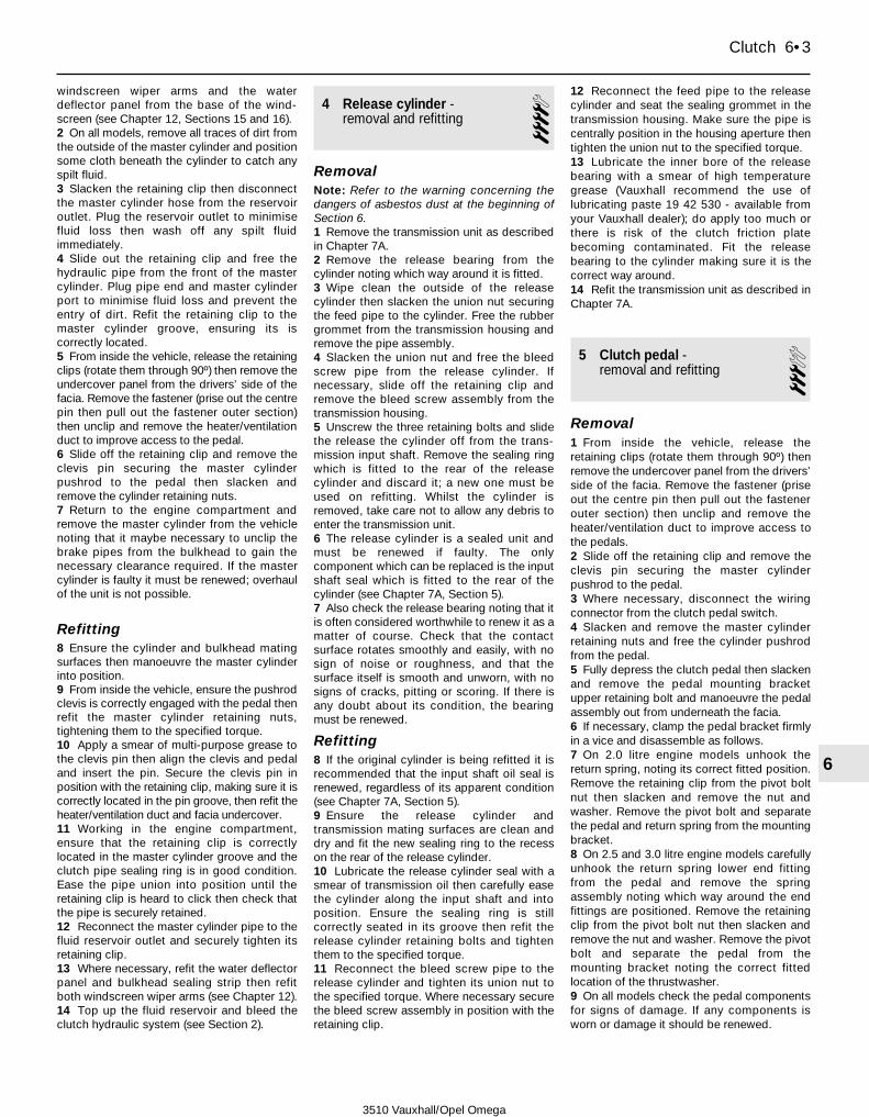
windscreen wiper arms and the waterdeflector panel from the base of the wind-screen (see Chapter 12, Sections 15 and 16).2 On all models, remove all traces of dirt fromthe outside of the master cylinder and positionsome cloth beneath the cylinder to catch anyspilt fluid.3 Slacken the retaining clip then disconnectthe master cylinder hose from the reservoiroutlet. Plug the reservoir outlet to minimisefluid loss then wash off any spilt fluidimmediately.4 Slide out the retaining clip and free thehydraulic pipe from the front of the mastercylinder. Plug pipe end and master cylinderport to minimise fluid loss and prevent theentry of dirt. Refit the retaining clip to themaster cylinder groove, ensuring its iscorrectly located.5 From inside the vehicle, release the retainingclips (rotate them through 90º) then remove theundercover panel from the drivers’ side of thefacia. Remove the fastener (prise out the centrepin then pull out the fastener outer section)then unclip and remove the heater/ventilationduct to improve access to the pedal.6 Slide off the retaining clip and remove theclevis pin securing the master cylinderpushrod to the pedal then slacken andremove the cylinder retaining nuts.7 Return to the engine compartment andremove the master cylinder from the vehiclenoting that it maybe necessary to unclip thebrake pipes from the bulkhead to gain thenecessary clearance required. If the mastercylinder is faulty it must be renewed; overhaulof the unit is not possible.
Refitting8 Ensure the cylinder and bulkhead matingsurfaces then manoeuvre the master cylinderinto position.9 From inside the vehicle, ensure the pushrodclevis is correctly engaged with the pedal thenrefit the master cylinder retaining nuts,tightening them to the specified torque.10 Apply a smear of multi-purpose grease tothe clevis pin then align the clevis and pedaland insert the pin. Secure the clevis pin inposition with the retaining clip, making sure it iscorrectly located in the pin groove, then refit theheater/ventilation duct and facia undercover.11 Working in the engine compartment,ensure that the retaining clip is correctlylocated in the master cylinder groove and theclutch pipe sealing ring is in good condition.Ease the pipe union into position until theretaining clip is heard to click then check thatthe pipe is securely retained.12 Reconnect the master cylinder pipe to thefluid reservoir outlet and securely tighten itsretaining clip.13 Where necessary, refit the water deflectorpanel and bulkhead sealing strip then refitboth windscreen wiper arms (see Chapter 12).14 Top up the fluid reservoir and bleed theclutch hydraulic system (see Section 2).
4 Release cylinder - removal and refitting 4
RemovalNote: Refer to the warning concerning thedangers of asbestos dust at the beginning ofSection 6.1 Remove the transmission unit as describedin Chapter 7A.2 Remove the release bearing from thecylinder noting which way around it is fitted.3 Wipe clean the outside of the releasecylinder then slacken the union nut securingthe feed pipe to the cylinder. Free the rubbergrommet from the transmission housing andremove the pipe assembly.4 Slacken the union nut and free the bleedscrew pipe from the release cylinder. Ifnecessary, slide off the retaining clip andremove the bleed screw assembly from thetransmission housing.5 Unscrew the three retaining bolts and slidethe release the cylinder off from the trans-mission input shaft. Remove the sealing ringwhich is fitted to the rear of the releasecylinder and discard it; a new one must beused on refitting. Whilst the cylinder isremoved, take care not to allow any debris toenter the transmission unit.6 The release cylinder is a sealed unit andmust be renewed if faulty. The onlycomponent which can be replaced is the inputshaft seal which is fitted to the rear of thecylinder (see Chapter 7A, Section 5).7 Also check the release bearing noting that itis often considered worthwhile to renew it as amatter of course. Check that the contactsurface rotates smoothly and easily, with nosign of noise or roughness, and that thesurface itself is smooth and unworn, with nosigns of cracks, pitting or scoring. If there isany doubt about its condition, the bearingmust be renewed.
Refitting8 If the original cylinder is being refitted it isrecommended that the input shaft oil seal isrenewed, regardless of its apparent condition(see Chapter 7A, Section 5).9 Ensure the release cylinder andtransmission mating surfaces are clean anddry and fit the new sealing ring to the recesson the rear of the release cylinder.10 Lubricate the release cylinder seal with asmear of transmission oil then carefully easethe cylinder along the input shaft and intoposition. Ensure the sealing ring is stillcorrectly seated in its groove then refit therelease cylinder retaining bolts and tightenthem to the specified torque.11 Reconnect the bleed screw pipe to therelease cylinder and tighten its union nut tothe specified torque. Where necessary securethe bleed screw assembly in position with theretaining clip.
12 Reconnect the feed pipe to the releasecylinder and seat the sealing grommet in thetransmission housing. Make sure the pipe iscentrally position in the housing aperture thentighten the union nut to the specified torque.13 Lubricate the inner bore of the releasebearing with a smear of high temperaturegrease (Vauxhall recommend the use oflubricating paste 19 42 530 - available fromyour Vauxhall dealer); do apply too much orthere is risk of the clutch friction platebecoming contaminated. Fit the releasebearing to the cylinder making sure it is thecorrect way around.14 Refit the transmission unit as described inChapter 7A.
5 Clutch pedal - removal and refitting 3
Removal1 From inside the vehicle, release theretaining clips (rotate them through 90º) thenremove the undercover panel from the drivers’side of the facia. Remove the fastener (priseout the centre pin then pull out the fastenerouter section) then unclip and remove theheater/ventilation duct to improve access tothe pedals.2 Slide off the retaining clip and remove theclevis pin securing the master cylinderpushrod to the pedal.3 Where necessary, disconnect the wiringconnector from the clutch pedal switch.4 Slacken and remove the master cylinderretaining nuts and free the cylinder pushrodfrom the pedal.5 Fully depress the clutch pedal then slackenand remove the pedal mounting bracketupper retaining bolt and manoeuvre the pedalassembly out from underneath the facia.6 If necessary, clamp the pedal bracket firmlyin a vice and disassemble as follows.7 On 2.0 litre engine models unhook thereturn spring, noting its correct fitted position.Remove the retaining clip from the pivot boltnut then slacken and remove the nut andwasher. Remove the pivot bolt and separatethe pedal and return spring from the mountingbracket.8 On 2.5 and 3.0 litre engine models carefullyunhook the return spring lower end fittingfrom the pedal and remove the springassembly noting which way around the endfittings are positioned. Remove the retainingclip from the pivot bolt nut then slacken andremove the nut and washer. Remove the pivotbolt and separate the pedal from themounting bracket noting the correct fittedlocation of the thrustwasher.9 On all models check the pedal componentsfor signs of damage. If any components isworn or damage it should be renewed.
Clutch 6•3
6
3510 Vauxhall/Opel Omega

Refitting10 If the pedal and bracket assembly hasbeen dismantled, apply a smear of multi-purpose grease to the pedal pivot bolt andbushes prior to reassembly.11 On 2.0 litre engine models, fit the returnspring to the pedal then refit the assembly tothe mounting bracket. Insert the pivot boltthen refit the washer and nut, tightening it tothe specified torque. Secure the pivot bolt nutin position with the retaining clip then hookthe return spring back into position.12 On 2.5 and 3.0 litre engine models refit thepedal to the mounting bracket then, makingsure the thrustwasher is correctly positioned,insert the pivot bolt. Refit the washer and nut tothe pivot bolt then tighten it to the specifiedtorque and secure in position with the retainingclip. Ensure the end fittings are correctly seatedon the return spring then refit the assembly tothe pedal and bracket making sure the smallerend fitting is positioned at the pedal end.13 On all models, manoeuvre the pedal andbracket assembly into position and refit theupper retaining bolt. Engage the mastercylinder pushrod with the pedal then refit themaster cylinder retaining nuts. Tighten boththe master cylinder nuts and the pedalbracket bolt to their specified torque settings.14 Apply a smear of multi-purpose grease tothe clevis pin then align the clevis and pedaland insert the pin. Secure the clevis pin in
position with the retaining clip, making sure itis correctly located in the pin groove15 Reconnect the wiring connector to theclutch pedal switch (where fitted) then refit theheater/ventilation duct and facia undercover.
6 Clutch assembly - removal, inspection and refitting
4Warning: Dust created by clutchwear and deposited on the clutchcomponents may contain
asbestos, which is a health hazard. DONOT blow it out with compressed air, orinhale any of it. DO NOT use petrol orpetroleum-based solvents to clean off thedust. Brake system cleaner or methylatedspirit should be used to flush the dust intoa suitable receptacle. After the clutchcomponents are wiped clean with rags,dispose of the contaminated rags andcleaner in a sealed, marked container.Note: Although some friction materials mayno longer contain asbestos, it is safest toassume that they do, and to take precautionsaccordingly.
Removal1 Remove the transmission as described inChapter 7A.2 Before disturbing the clutch, use chalk or amarker pen to mark the relationship of thepressure plate assembly to the flywheel.3 Working in a diagonal sequence, evenlyand progressively slacken the pressure platebolts by half a turn at a time, until springpressure is released and the bolts can beunscrewed by hand.Caution: To avoid the risk of distorting thepressure plate diaphragm spring it is mostimportant that the pressure plate bolts areevenly slackened. To avoid this, on modelswith a normal flywheel (it is not possible ifa dual-mass flywheel is fitted) Vauxhalldealers use a special tool to depress thediaphragm spring and then hold the springin its compressed state by fitting specialclips to the pressure plate assembly (seeillustration). Removal of the clips andfitting to a new pressure plate will then
require the use of a press. However,provided adequate care is taken tounscrew the pressure plate bolts evenly nodistortion should occur.4 Remove the pressure plate assembly andcollect the friction plate, noting which wayround the friction plate is fitted.
InspectionNote: Due to the amount of work necessary toremove and refit clutch components, it isusually considered good practice to renew theclutch friction plate, pressure plate assemblyand release bearing as a matched set, even ifonly one of these is actually worn enough torequire renewal. It is also worth consideringthe renewal of the clutch components on apreventive basis if the engine and/ortransmission have been removed for someother reason.5 Remove the clutch assembly.6 When cleaning clutch components, readfirst the warning at the beginning of thisSection; remove dust using a clean, dry cloth,and working in a well-ventilated atmosphere.7 Check the friction plate facings for signs ofwear, damage or oil contamination. If thefriction material is cracked, burnt, scored ordamaged, or if it is contaminated with oil orgrease (shown by shiny black patches), thefriction plate must be renewed.8 If the friction material is still serviceable,check that the centre boss splines areunworn, that the torsion springs are in goodcondition and securely fastened, and that allthe rivets are tight. If any wear or damage isfound, the friction plate must be renewed.9 If the friction material is fouled with oil, thismust be due to an oil leak from the crankshaftoil seal, from the sump-to-cylinder block joint,or from the release cylinder assembly (eitherthe input shaft seal or the sealing ring). Renewthe crankshaft oil seal or repair the sump jointas described in the relevant part of Chapter 2,before installing the new friction plate. Theclutch release cylinder is covered in Section 4.10 Check the pressure plate assembly forobvious signs of wear or damage; shake it tocheck for loose rivets or worn or damagedfulcrum rings, and check that the drive strapssecuring the pressure plate to the cover donot show signs (such as a deep yellow or bluediscoloration) of overheating. If the diaphragmspring is worn or damaged, or if its pressure isin any way suspect, the pressure plateassembly should be renewed.11 Examine the machined bearing surfacesof the pressure plate and of the flywheel; theyshould be clean, completely flat, and free fromscratches or scoring. If either is discolouredfrom excessive heat, or shows signs ofcracks, it should be renewed - although minordamage of this nature can sometimes bepolished away using emery paper.12 Also check that the release cylinderbearing rotates smoothly and easily, with nosign of noise or roughness. Also check thatthe surface itself is smooth and unworn, with
6•4 Clutch
6.3 Vauxhall service tool for depressingthe diaphragm spring on engines with a
normal flywheel
Arrows indicate where pressure plateretaining clips are fitted
6.14 Refit the friction plate making sure itsspring hub assembly faces away from the
flywheel6.17 Centralising the friction plate with an
aligning tool
3510 Vauxhall/Opel Omega

no signs of cracks, pitting or scoring. If thereis any doubt about its condition, the bearingshould be renewed (see Section 4).
Refitting13 On reassembly, ensure that the bearingsurfaces of the flywheel and pressure plateare completely clean, smooth, and free fromoil or grease. Use solvent to remove anyprotective grease from new components.14 Fit the friction plate so that its spring hubassembly faces away from the flywheel; theremay also be a marking showing which wayround the plate is to be refitted (see illustration).15 Refit the pressure plate assembly,aligning the marks made on dismantling (if theoriginal pressure plate is re-used). Fit the
pressure plate bolts, but tighten them onlyfinger-tight, so that the friction plate can stillbe moved.16 The friction plate must now becentralised, so that when the transmission isrefitted, its input shaft will pass through thesplines at the centre of the friction plate.17 Centralisation can be achieved by passinga screwdriver or other long bar through thefriction plate and into the hole in thecrankshaft; the friction plate can then bemoved around until it is centred on thecrankshaft hole. Alternatively, a clutch-aligning -tool can be used to eliminate theguesswork; these can be obtained from mostaccessory shops (see illustration). A home-made aligning tool can be fabricated from a
length of metal rod or wooden dowel whichfits closely inside the crankshaft hole, and hasinsulating tape wound around it to match thediameter of the friction plate splined hole.18 When the friction plate is centralised,tighten the pressure plate bolts evenly and ina diagonal sequence to the specified torquesetting. Once all the bolts have beentightened remove the alignment tool. Wherenecessary, use the service tool to remove theretaining clips from the pressure plate.Caution: To avoid the risk of distorting thepressure plate diaphragm spring it is mostimportant that the pressure plate bolts areevenly and progressively tightened.19 Refit the transmission as described inChapter 7A.
Clutch 6•5
6
3510 Vauxhall/Opel Omega

3510 Vauxhall/Opel Omega
7A•1
7A
Chapter 7 Part A:Manual transmission
GeneralType . . . . . . . . . . . . . . . . . . . . . . . . . . . . . . . . . . . . . . . . . . . . . . . . . . . . Manual, five forward speeds and reverse. Synchromesh on all forward
speedsIdentification code:
2.0 and 2.5 litre engines . . . . . . . . . . . . . . . . . . . . . . . . . . . . . . . . . . . R253.0 litre engines . . . . . . . . . . . . . . . . . . . . . . . . . . . . . . . . . . . . . . . . . . R28
Torque wrench settings Nm lbf ftDrain plug . . . . . . . . . . . . . . . . . . . . . . . . . . . . . . . . . . . . . . . . . . . . . . . . 30 22Engine to transmission support bracket bolts - 2.0 litre engines with one-piece sump:
Bracket-to-engine bolt . . . . . . . . . . . . . . . . . . . . . . . . . . . . . . . . . . . . 40 30Bracket-to-transmission bolts . . . . . . . . . . . . . . . . . . . . . . . . . . . . . . 22 16
Filler plug . . . . . . . . . . . . . . . . . . . . . . . . . . . . . . . . . . . . . . . . . . . . . . . . 30 22Gearchange lever retaining bolts . . . . . . . . . . . . . . . . . . . . . . . . . . . . . . 10 7Gearchange linkage rod clamp bolt:
Stage 1 . . . . . . . . . . . . . . . . . . . . . . . . . . . . . . . . . . . . . . . . . . . . . . . . 14 10Stage 2 . . . . . . . . . . . . . . . . . . . . . . . . . . . . . . . . . . . . . . . . . . . . . . . . Angle-tighten a further 135 to 180º
Propeller shaft flange nut . . . . . . . . . . . . . . . . . . . . . . . . . . . . . . . . . . . . 150 110Reversing light switch . . . . . . . . . . . . . . . . . . . . . . . . . . . . . . . . . . . . . . . 20 15Transmission unit mounting bolts:
Transmission-to-cylinder block bolts . . . . . . . . . . . . . . . . . . . . . . . . . 60 44Transmission-to-sump flange bolts (engines with a two-piece sump) . 40 30Rear upper mounting bracket bolts . . . . . . . . . . . . . . . . . . . . . . . . . . 22 16Rear mounting crossmember-to-body bolts . . . . . . . . . . . . . . . . . . . 45 33
Gearchange linkage - adjustment . . . . . . . . . . . . . . . . . . . . . . . . . . . 3Gearchange linkage - removal and refitting . . . . . . . . . . . . . . . . . . . 4General information . . . . . . . . . . . . . . . . . . . . . . . . . . . . . . . . . . . . . . 1Oil seals - renewal . . . . . . . . . . . . . . . . . . . . . . . . . . . . . . . . . . . . . . . 5
Reversing light switch - testing, removal and refitting . . . . . . . . . . . 6Transmission - removal and refitting . . . . . . . . . . . . . . . . . . . . . . . . . 7Transmission oil - draining, refilling and checking . . . . . . . . . . . . . . . 2Transmission overhaul - general information . . . . . . . . . . . . . . . . . . 8
Specifications
Contents
Easy, suitable fornovice with littleexperience
Fairly easy, suitablefor beginner withsome experience
Fairly difficult,suitable for competentDIY mechanic
Difficult, suitable forexperienced DIYmechanic
Very difficult,suitable for expert DIYor professional
Degrees of difficulty
54321
1 General information
1 The transmission is contained in a cast-aluminium alloy casing bolted to the rear ofthe engine. Drive is transmitted from thecrankshaft via the clutch to the transmissioninput shaft, which has a splined extension toaccept the clutch friction plate. Thetransmission input shaft transfers drive to theauxiliary shaft which is positioned directlybelow the main shaft, both shafts beingparallel to the crankshaft and propeller shaft.
2 Gear selection is via a floor-mounted leverand selector linkage mechanism. The selectorlinkage cause the appropriate selector fork tomove its respective synchro-sleeve along theshaft, to lock the gear pinion to the synchro-hub. Since the synchro-hubs are splined tothe main shaft, this locks the pinion to theshaft, so that drive can be transmitted. Toensure that gear-changing can be madequickly and quietly, a synchro-mesh system isfitted to all forward gears, consisting of baulkrings and spring-loaded fingers, as well as thegear pinions and synchro-hubs. The synchro-mesh cones are formed on the mating facesof the baulk rings and gear pinions.
2 Transmission oil - draining, refilling and checking 3
Note: There have been three different types ofoil used in the manual transmission unit byVauxhall (see Lubricants and fluids in Weeklychecks). Bearing in mind that the different typesof oil should never be mixed, it is essential thatthe transmission unit is refilled either with thesame type of oil as that which has been drainedor the very latest specification oil (used inproduction from 1999 model year onwards). If itis not known what type of oil has been drained,

the transmission unit should be flushed beforefilling with the latest specification oil. To do this,using the latest type of oil (part number 19 40768), refill the transmission unit so that the oillevel is right up to the base of the filler plugaperture then refit the plug. Take the vehicle ona journey of approximately 15 miles (20 km)then, on your return, drain the oil out again andrefill the transmission as normal with the latesttype of oil. If the flushing process has alreadybeen carried out an early (pre 1999 model year)vehicle, the drain plug will be marked with a dotof green paint.
Draining1 This operation is much quicker and moreefficient if the car is first taken on a journey ofsufficient length to warm the engine/trans-mission up to normal operating temperature.2 Park the car on level ground, switch off theignition and apply the handbrake firmly. Forimproved access, jack up the front of the carand support it securely on axle stands. Notethat the car must be lowered to the groundand level, to ensure accuracy, when refillingand checking the oil level.3 Remove all traces of dirt then unscrew thefiller plug from the right-hand side of thetransmission housing.4 Position a suitable container under thedrain plug situated on the base of thetransmission housing then unscrew the drainplug and allow the oil to drain completely intothe container (see illustration). Clean boththe filler and the drain plugs, being especiallycareful to wipe any metallic particles off themagnetic inserts.
Warning: If the oil is hot, takeprecautions against scalding.
5 When the oil has finished draining, cleanthe drain plug threads and those of thetransmission casing then refit the drain plugand tighten to the specified torque.
Refilling6 Refilling the transmission is an extremelyawkward operation. Above all, allow plenty oftime for the oil level to settle properly beforechecking it. Note that the car must be parkedon flat level ground when checking the oillevel.7 Refill the transmission with the exactamount of the specified type of oil then checkthe oil level as described in paragraphs 12and 13. When the level is correct, refit the fillerplug and tighten it to the specified torque.8 Take the vehicle on a short journey so thatthe new oil is distributed fully around thetransmission components.9 On your return, park the vehicle on levelground and recheck the transmission oil levelagain to ensure the level is correct.
CheckingNote: It is essential that the transmission unitis topped up with the same type of oil as thatwith which it is filled; there are three differenttypes of oil available and they must never bemixed. If it is not known which type of oil thetransmission is filled with, it is recommendedthat the unit is drained, flushed and thenrefilled with the latest type of oil (see Note atthe start of the Section).10 Position the vehicle over an inspection pit,on vehicle ramps, or jack it up, but make surethat it is level. The oil level must be checkedbefore the car is driven, or at least 5 minutesafter the engine has been switched off. If theoil is checked immediately after driving thecar, some of the oil will remain distributedaround the transmission components,resulting in an inaccurate level reading.11 Wipe clean the area around the filler plugwhich is located on the right-hand side of thetransmission housing. Unscrew the plug andclean it.12 To check the oil level, it will be necessaryto fabricate a dipstick. This can be made out
of a piece of welding rod with a right-angledbend in it. Insert the rod into the filler hole andcheck the oil level; the oil level should beapproximately 9 mm below the lower edge ofthe filler plug aperture.Caution: When checking the oil level, takegreat care not to drop the dipstick into thetransmission unit.13 If topping up is necessary, add the correcttype of oil through the filler hole until the oillevel is correct. Note: Do not overfill thetransmission as this will adversely affect thegearchange action. Any excess oil must beeither be siphoned or drained from thetransmission unit before the vehicle is used.14 Once the transmission oil level is correct,refit the filler plug and tighten it to thespecified torque.
3 Gearchange linkage -adjustment 3
Note: Vauxhall service tool KM-631A will berequired to carry out this procedure.1 Adjustment of the gearchange linkage is nota routine operation and should only beneeded if the mechanism has been removed.If the gearchange action is stiff or imprecise,check that it is correctly adjusted as follows.2 Position the gearchange lever in the neutralposition, firmly apply the handbrake then jackup the front of the vehicle and support it onaxle stands.3 Remove the retaining clips securing theprotective cover to the vehicle underbodythen fold the cover forwards to gain access tothe clamp bolt on the rear end of thegearchange linkage rod. Slacken the clampbolt so that the end fitting is free to moveeasily in the rod (see illustrations).4 From inside the vehicle, unclip thegearchange lever gaiter from the centreconsole and fold it back over the lever. Freethe rubber gaiter from the mounting plate andfold it back to gain access to the base of thegearchange lever.5 Lock the gearchange lever in position byfitting the service tool (KM-631A) into thegearchange lever housing whilst holding thelever over to the right.
7A•2 Manual transmission
2.4 Removing the transmission drain plug
3.3a Release the retaining clips (arrowed) . . .
3.3b . . . and peel back the protectivecover . . .
3.3c . . . to gain access to the gearchangelinkage clamp bolt (arrowed)
3510 Vauxhall/Opel Omega
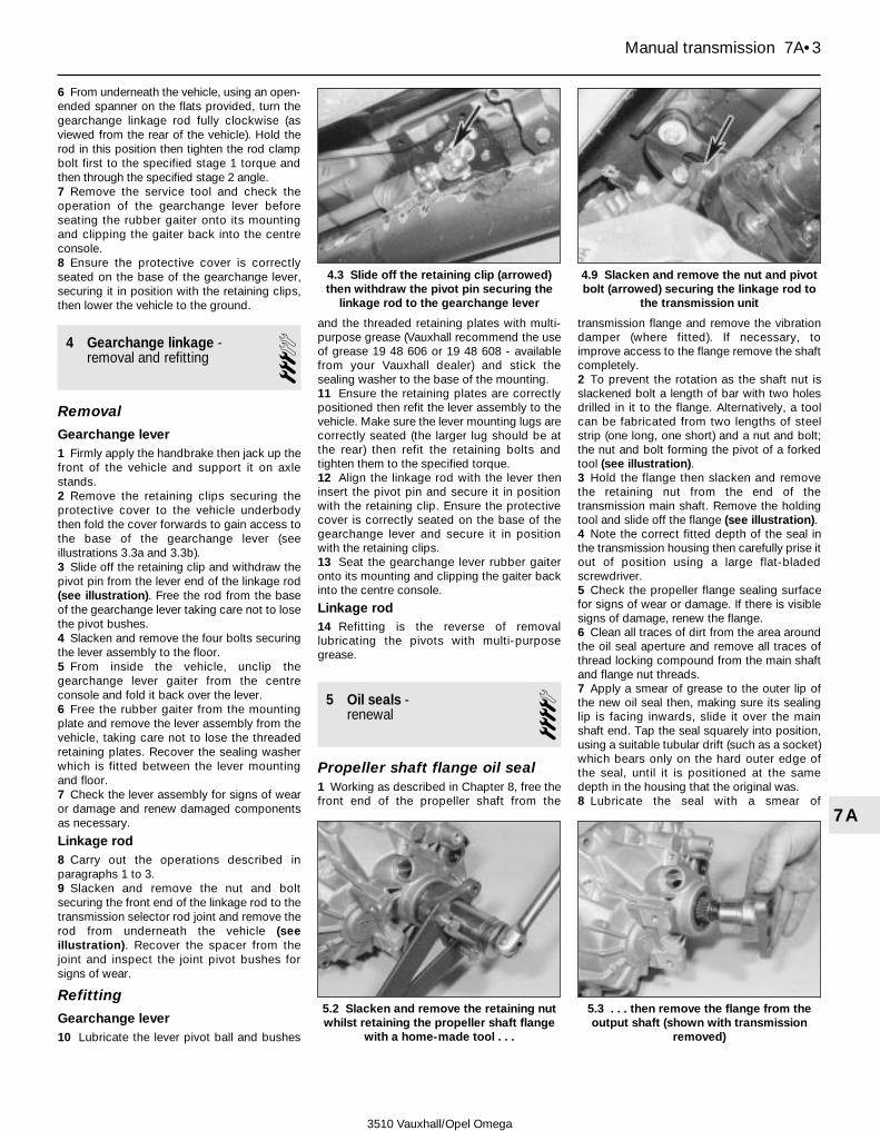
6 From underneath the vehicle, using an open-ended spanner on the flats provided, turn thegearchange linkage rod fully clockwise (asviewed from the rear of the vehicle). Hold therod in this position then tighten the rod clampbolt first to the specified stage 1 torque andthen through the specified stage 2 angle.7 Remove the service tool and check theoperation of the gearchange lever beforeseating the rubber gaiter onto its mountingand clipping the gaiter back into the centreconsole.8 Ensure the protective cover is correctlyseated on the base of the gearchange lever,securing it in position with the retaining clips,then lower the vehicle to the ground.
4 Gearchange linkage -removal and refitting 3
Removal
Gearchange lever1 Firmly apply the handbrake then jack up thefront of the vehicle and support it on axlestands.2 Remove the retaining clips securing theprotective cover to the vehicle underbodythen fold the cover forwards to gain access tothe base of the gearchange lever (seeillustrations 3.3a and 3.3b).3 Slide off the retaining clip and withdraw thepivot pin from the lever end of the linkage rod(see illustration). Free the rod from the baseof the gearchange lever taking care not to losethe pivot bushes.4 Slacken and remove the four bolts securingthe lever assembly to the floor.5 From inside the vehicle, unclip thegearchange lever gaiter from the centreconsole and fold it back over the lever.6 Free the rubber gaiter from the mountingplate and remove the lever assembly from thevehicle, taking care not to lose the threadedretaining plates. Recover the sealing washerwhich is fitted between the lever mountingand floor.7 Check the lever assembly for signs of wearor damage and renew damaged componentsas necessary.
Linkage rod8 Carry out the operations described inparagraphs 1 to 3.9 Slacken and remove the nut and boltsecuring the front end of the linkage rod to thetransmission selector rod joint and remove therod from underneath the vehicle (seeillustration). Recover the spacer from thejoint and inspect the joint pivot bushes forsigns of wear.
Refitting
Gearchange lever10 Lubricate the lever pivot ball and bushes
and the threaded retaining plates with multi-purpose grease (Vauxhall recommend the useof grease 19 48 606 or 19 48 608 - availablefrom your Vauxhall dealer) and stick thesealing washer to the base of the mounting.11 Ensure the retaining plates are correctlypositioned then refit the lever assembly to thevehicle. Make sure the lever mounting lugs arecorrectly seated (the larger lug should be atthe rear) then refit the retaining bolts andtighten them to the specified torque.12 Align the linkage rod with the lever theninsert the pivot pin and secure it in positionwith the retaining clip. Ensure the protectivecover is correctly seated on the base of thegearchange lever and secure it in positionwith the retaining clips.13 Seat the gearchange lever rubber gaiteronto its mounting and clipping the gaiter backinto the centre console.
Linkage rod14 Refitting is the reverse of removallubricating the pivots with multi-purposegrease.
5 Oil seals - renewal 4
Propeller shaft flange oil seal1 Working as described in Chapter 8, free thefront end of the propeller shaft from the
transmission flange and remove the vibrationdamper (where fitted). If necessary, toimprove access to the flange remove the shaftcompletely.2 To prevent the rotation as the shaft nut isslackened bolt a length of bar with two holesdrilled in it to the flange. Alternatively, a toolcan be fabricated from two lengths of steelstrip (one long, one short) and a nut and bolt;the nut and bolt forming the pivot of a forkedtool (see illustration).3 Hold the flange then slacken and removethe retaining nut from the end of thetransmission main shaft. Remove the holdingtool and slide off the flange (see illustration).4 Note the correct fitted depth of the seal inthe transmission housing then carefully prise itout of position using a large flat-bladedscrewdriver.5 Check the propeller flange sealing surfacefor signs of wear or damage. If there is visiblesigns of damage, renew the flange.6 Clean all traces of dirt from the area aroundthe oil seal aperture and remove all traces ofthread locking compound from the main shaftand flange nut threads.7 Apply a smear of grease to the outer lip ofthe new oil seal then, making sure its sealinglip is facing inwards, slide it over the mainshaft end. Tap the seal squarely into position,using a suitable tubular drift (such as a socket)which bears only on the hard outer edge ofthe seal, until it is positioned at the samedepth in the housing that the original was.8 Lubricate the seal with a smear of
Manual transmission 7A•3
7A
4.3 Slide off the retaining clip (arrowed)then withdraw the pivot pin securing the
linkage rod to the gearchange lever
4.9 Slacken and remove the nut and pivotbolt (arrowed) securing the linkage rod to
the transmission unit
5.2 Slacken and remove the retaining nutwhilst retaining the propeller shaft flange
with a home-made tool . . .
5.3 . . . then remove the flange from theoutput shaft (shown with transmission
removed)
3510 Vauxhall/Opel Omega

transmission oil then carefully slide thepropeller flange into position, taking care notto damage the seal lip.9 Apply a few drops of thread lockingcompound (Vauxhall recommend the use oflocking compound 15 10 181 - available fromyour Vauxhall dealer) to the threads of theflange retaining nut. Refit the nut and tighten itto the specified torque using the methodemployed on removal to prevent rotation.10 Reconnect/refit the propeller shaft asdescribed in Chapter 8 then check the trans-mission oil level as described in Section 2.
Input shaft oil sealNote: A leak around the transmission inputshaft can come either from the input shaft sealor from the clutch release cylinder sealingring. Whilst the cylinder is removed renewboth items regardless of their apparentcondition.11 Remove the clutch release cylinder asdescribed in Chapter 6.12 Note the correct fitted depth of the seal inthe release cylinder then carefully prise it out ofposition using a large flat-bladed screwdriver.13 Clean all traces of dirt from the areaaround the oil seal aperture and apply a smearof grease to the outer lip of the new oil seal.Making sure its sealing lip is facing outward(towards the transmission unit when thecylinder is fitted), seat the seal in the rear ofthe cylinder and press it squarely into positionuntil it is positioned at the same depth in thehousing that the original was. If necessary, tapthe seal into position, using a suitable tubulardrift (such as a socket) which bears only onthe hard outer edge of the seal.14 Fit a new sealing ring and refit the releasecylinder as described in Chapter 6.
6 Reversing light switch -testing, removal and refitting 2
Testing1 The reversing light circuit is controlled by aplunger-type switch that is screwed into therear of the transmission, above and to the leftof the propeller shaft. If a fault develops in thecircuit, first ensure that the circuit fuse has notblown.2 To test the switch, disconnect the wiringconnector. Use a multimeter (set to theresistance function) or a battery-and-bulb testcircuit to check that there is continuitybetween the switch terminals only whenreverse gear is selected. If this is not the case,and there are no obvious breaks or otherdamage to the wires, the switch is faulty, andmust be renewed.
Removal3 Firmly apply the handbrake then jack up thefront of the vehicle and support it on axlestands.
4 Disconnect the wiring connector, thenunscrew the switch and remove it from thetransmission casing along with its sealingwasher.
Refitting5 Fit a new sealing washer to the switch, thenscrew it back into position in the top of thetransmission housing and tighten it to thespecified torque. Reconnect the wiringconnector and test the operation of the circuitthen lower the vehicle to the ground.
7 Transmission - removal and refitting 4
Removal1 Disconnect the battery negative terminal.Note: On models with a Vauxhall anti-theftwarning system (ATWS), the battery negativeterminal must be disconnected within 15seconds of the ignition being switched off toprevent the alarm system being triggered.2 Chock the rear wheels, then firmly apply thehandbrake. Jack up the front of the vehicle,and securely support it on axle stands. Undothe retaining bolts and remove the undercoverfrom beneath the engine/transmission unit.3 Trace the clutch hydraulic hose/pipe backfrom the transmission unit to connector on theengine compartment bulkhead. Minimise fluidloss by clamping the fluid supply hose linkingthe fluid reservoir to the clutch master cylinderthen release the connector from the bulkhead.Slide out the retaining clip and separate thetwo halves of the pipe, plugging the pipe endsto minimise fluid loss and prevent the entry ofdirt. Refit the retaining clip to the connectorgroove, ensuring its is correctly located, thencheck the lower end of the pipe is free toremoved with the transmission unit.Caution: Do no depress the clutch pedalwhilst the hose is disconnected.4 Disconnect the wiring connector from thereversing light switch, which is located at therear of the transmission unit.5 Working as described in Chapter 8, unboltthe front end of the propeller shaft from thetransmission flange and remove the vibrationdamper (where fitted). Position the propellershaft to the right of the transmission unit andtie it to the vehicle underbody.6 Remove the gearchange linkage rod asdescribed in Section 4 and proceed asdescribed under the relevant sub-heading.
2.0 litre engines7 On SOHC engines, disconnect the wiringconnector from the DIS module. Slacken andremove the module mounting bracketretaining bolts, noting the correct fittedlocation of the engine lifting bracket, then freethe wiring harness and remove the DISmodule and bracket from the rear of the
cylinder head. Free the HT leads from theirretaining clips and position the assembly clearof the transmission unit.8 On all models unclip the oxygen sensorwiring connector from transmission unit anddisconnect it.9 Slacken and remove the exhaust systemfront pipe mounting bracket retaining boltsand remove the bracket. Also remove thebolts securing the front pipe to theintermediate pipe and separate the twoexhaust sections.10 On models with a one-piece engine sump,slacken and remove the bolts securing thesupport brackets to the transmission housingand sides of the cylinder block. Remove bothbrackets from the engine then remove theflywheel lower cover plate from the base ofthe transmission housing.11 On all models slacken and remove thetwo bolts securing the rear of the transmissionunit to the upper mounting bracket.12 Place a jack with a block of wood beneaththe transmission, and raise the jack to takethe weight of the transmission.13 With the transmission securely supported,slacken and remove the bolts securing thetransmission unit rear mounting crossmemberto the vehicle body.14 Lower the transmission unit slightly thenslacken and remove all the bolts securing thetransmission housing to the engine unit. Notethe correct fitted positions of each bolt, andthe necessary brackets, as they are removed,to use as a reference on refitting. Make a finalcheck that all components have beendisconnected, and are positioned clear of thetransmission so that they will not hinder theremoval procedure.15 With the bolts removed, move the trolleyjack and transmission to the rear, to free itfrom its locating dowels. Once thetransmission is free, lower the jack andmanoeuvre the unit out from under thevehicle. Remove the locating dowels from thetransmission or engine if they are loose, andkeep them in a safe place.16 With the transmission removed from thevehicle, slide off the clutch release bearingfrom the release cylinder and check it forwear. The bearing contact surface shouldrotate smoothly and easily, with no sign ofnoise or roughness, and that the surface itselfis smooth and unworn, with no signs ofcracks, pitting or scoring. If there is any doubtabout its condition, the bearing should berenewed.
2.5 and 3.0 litre engines17 Remove both exhaust system front pipesas described in Chapter 4A.18 Remove the transmission unit asdescribed in paragraphs 11 to 16.
Refitting19 The transmission is refitted by a reversalof the removal procedure, bearing in mind thefollowing points.
7A•4 Manual transmission
3510 Vauxhall/Opel Omega

a) Remove all traces of dirt and grease fromthe input shaft splines and the contactsurfaces of the clutch release bearing andrelease cylinder. Lubricate the inner boreof the release bearing with a smear ofhigh temperature grease (Vauxhallrecommend the use of lubricating paste19 42 530 - available from your Vauxhalldealer) and apply a thin smear of greaseto the input shaft splines; do apply toomuch or there is risk of the clutch frictionplate becoming contaminated. Fit therelease bearing to the cylinder makingsure it is the correct way around.
b) Ensure the locating dowels are correctlypositioned prior to refitting thetransmission to the engine. As thetransmission unit is fitted, take great carenot to allow the weight of the unit to hangon the input shaft.
c) Remove all traces of locking compoundfrom the transmission unit rear mountingcrossmember to body bolt threads. Applya few drops of thread locking compound(Vauxhall recommend the use of lockingcompound 15 10 181 - available fromyour Vauxhall dealer) to the threads ofeach bolt prior to refitting and tightenboth bolts to the specified torque.
d) Tighten all nuts and bolts to the specifiedtorque (where given).
e) Ensure the clutch hydraulic pipeconnector sealing ring is in goodcondition before clipping the hose/pipeend fitting into position. Ensure the endfitting is securely retained by its clip thenremove the clamp from the mastercylinder hose and bleed the hydraulicsystem as described in Chapter 6.
f) On completion check and, if necessary,top up the transmission oil level asdescribed in Section 2. If necessary, alsoadjust the gearchange linkage asdescribed in Section 3.
8 Transmission overhaul -general information 5
1 Overhauling a manual transmission unit is adifficult and involved job for the DIY homemechanic. In addition to dismantling andreassembling many small parts, clearancesmust be precisely measured and, if necessary,changed by selecting shims and spacers.Internal transmission components are alsooften difficult to obtain, and in many instances,
extremely expensive. Because of this, if thetransmission develops a fault or becomesnoisy, the best course of action is to have theunit overhauled by a specialist repairer, or toobtain an exchange reconditioned unit.2 Nevertheless, it is not impossible for themore experienced mechanic to overhaul thetransmission, provided the special tools areavailable, and the job is done in a deliberatestep-by-step manner, so that nothing isoverlooked.3 The tools necessary for an overhaul includeinternal and external circlip pliers, bearingpullers, a slide hammer, a set of pin punches,a dial test indicator, and possibly a hydraulicpress. In addition, a large, sturdy workbenchand a vice will be required.4 During dismantling of the transmission,make careful notes of how each component isfitted, to make reassembly easier and moreaccurate.5 Before dismantling the transmission, it willhelp if you have some idea what area ismalfunctioning. Certain problems can beclosely related to specific areas in thetransmission, which can make componentexamination and replacement easier. Refer tothe Fault finding Section of this manual formore information.
Manual transmission 7A•5
7A
3510 Vauxhall/Opel Omega

3510 Vauxhall/Opel Omega
7B•1
7B
Chapter 7 Part B:Automatic transmission
GeneralType . . . . . . . . . . . . . . . . . . . . . . . . . . . . . . . . . . . . . . . . . . . . . . . . . . . . Four-speed electronically-controlled automatic with three (normal,
sport and winter) driving modesIdentification code*:
2.0 and 2.5 litre models . . . . . . . . . . . . . . . . . . . . . . . . . . . . . . . . . . . AR253.0 litre models . . . . . . . . . . . . . . . . . . . . . . . . . . . . . . . . . . . . . . . . . . AR35
*The code is marked on the identification plate which is attached to the left-hand side of the transmission unit, behind the selector lever.
Torque wrench settings Nm Ibf ftEngine-to-transmission support bracket bolts - 2.0 litre engines with one-piece sump:
Bracket-to-engine bolt . . . . . . . . . . . . . . . . . . . . . . . . . . . . . . . . . . . . 40 30Bracket-to-transmission bolts . . . . . . . . . . . . . . . . . . . . . . . . . . . . . . 22 16
Fluid cooler pipe unions:Union bolts . . . . . . . . . . . . . . . . . . . . . . . . . . . . . . . . . . . . . . . . . . . . . 25 18Union nut . . . . . . . . . . . . . . . . . . . . . . . . . . . . . . . . . . . . . . . . . . . . . . 30 22
Fluid filter retaining bolts . . . . . . . . . . . . . . . . . . . . . . . . . . . . . . . . . . . . 20 15Fluid level plug . . . . . . . . . . . . . . . . . . . . . . . . . . . . . . . . . . . . . . . . . . . . 33 24Output speed sensor bolt . . . . . . . . . . . . . . . . . . . . . . . . . . . . . . . . . . . . 12 9Propeller shaft centre bearing bracket bolts . . . . . . . . . . . . . . . . . . . . . 20 15Propeller shaft flange nut . . . . . . . . . . . . . . . . . . . . . . . . . . . . . . . . . . . . 100 74Rear mounting crossmember-to-body bolts . . . . . . . . . . . . . . . . . . . . . 45 33Selector lever position switch bolts . . . . . . . . . . . . . . . . . . . . . . . . . . . . 13 10Selector linkage fixings:
Linkage rod clamp bolt . . . . . . . . . . . . . . . . . . . . . . . . . . . . . . . . . . . . 8 6Lever pivot shaft nut . . . . . . . . . . . . . . . . . . . . . . . . . . . . . . . . . . . . . . 28 21Lever to transmission selector shaft nut . . . . . . . . . . . . . . . . . . . . . . . 20 15
Sump retaining bolts . . . . . . . . . . . . . . . . . . . . . . . . . . . . . . . . . . . . . . . . 12 9Torque converter-to-driveplate bolts . . . . . . . . . . . . . . . . . . . . . . . . . . . 30 22Transmission unit mounting bolts:
Transmission-to-cylinder block bolts . . . . . . . . . . . . . . . . . . . . . . . . . 60 44Transmission-to-sump flange bolts (engines with a two-piece sump) . . . . . . . . . . . . . . . . . . . . . . . . . . . . 40 30
Automatic transmission - removal and refitting . . . . . . . . . . . . . . . . . 9Automatic transmission fluid level check . . . . . . . . . . . .See Chapter 1Automatic transmission overhaul - general information . . . . . . . . . . 10Fluid cooler - general information . . . . . . . . . . . . . . . . . . . . . . . . . . . 7General information . . . . . . . . . . . . . . . . . . . . . . . . . . . . . . . . . . . . . . 1Oil seals - renewal . . . . . . . . . . . . . . . . . . . . . . . . . . . . . . . . . . . . . . . 6
Selector lever assembly - removal and refitting . . . . . . . . . . . . . . . . 5Selector linkage - adjustment . . . . . . . . . . . . . . . . . . . . . . . . . . . . . . 3Selector linkage - removal and refitting . . . . . . . . . . . . . . . . . . . . . . . 4Transmission control system electrical components - removal and
refitting . . . . . . . . . . . . . . . . . . . . . . . . . . . . . . . . . . . . . . . . . . . . . . 8Transmission fluid - draining and refilling . . . . . . . . . . . . . . . . . . . . . 2
Specifications
Contents
Easy, suitable fornovice with littleexperience
Fairly easy, suitablefor beginner withsome experience
Fairly difficult,suitable for competentDIY mechanic
Difficult, suitable forexperienced DIYmechanic
Very difficult,suitable for expert DIYor professional
Degrees of difficulty
54321
1 General information
Note: On later models, if the battery isdisconnected with the selector lever in the Pposition, the lever will be locked in position. To
manually release the lever, carefully unclip theselector lever gaiter from the top of the centreconsole then, depress the yellow release leveron the left-hand side of the selector lever witha pen or screwdriver (see illustrations). Theselector lever can then be moved as normal.1 Most models covered in this manual wereoffered with the option of a four-speed,
electronically-controlled automatic trans-mission, consisting of a torque converter, anepicyclic geartrain, and hydraulically-operatedclutches and brakes. The unit is controlled bythe electronic control unit (ECU) viaelectrically-operated solenoid valves. Thetransmission unit has three driving modes;normal (economy), sport and winter modes.
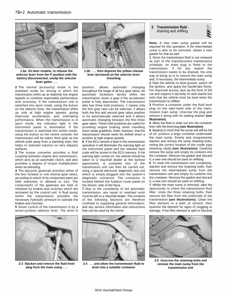
2 The normal (economy) mode is thestandard mode for driving in which thetransmission shifts up at relatively low enginespeeds to combine reasonable performancewith economy. If the transmission unit isswitched into sport mode, using the buttonon the selector lever, the transmission shiftsup only at high engine speeds, givingimproved acceleration and overtakingperformance. When the transmission is insport mode, the indicator light in theinstrument panel is illuminated. If thetransmission is switched into winter mode,using the button on the centre console, thetransmission will be select third gear as thevehicle pulls away from a standing start; thishelps to maintain traction on very slipperysurfaces.3 The torque converter provides a fluidcoupling between engine and transmission,which acts as an automatic clutch, and alsoprovides a degree of torque multiplicationwhen accelerating.4 The epicyclic geartrain provides either ofthe four forward or one reverse gear ratios,according to which of its component parts areheld stationary or allowed to turn. Thecomponents of the geartrain are held orreleased by brakes and clutches which areactivated by the control unit. A fluid pumpwithin the transmission provides thenecessary hydraulic pressure to operate thebrakes and clutches.5 Driver control of the transmission is by aseven-position selector lever. The drive D
position, allows automatic changingthroughout the range of all four gear ratios. Anautomatic kickdown facility shifts thetransmission down a gear if the acceleratorpedal is fully depressed. The transmissionalso has three hold positions, 1 means onlythe first gear ratio can be selected, 2 allowsboth the first and second gear ratios positionto be automatically selected and 3 allowsautomatic changing between the first threegear ratios. These hold positions are useful forproviding engine braking when travellingdown steep gradients. Note, however, that thetransmission should never be shifted down aposition at high engine speeds.6 If the ECU senses a fault in the transmissionoperation it will illuminate the warning light onthe instrument panel and the relevant faultcode will be stored in the ECU memory. If thewarning light comes on, the vehicle should betaken to a Vauxhall dealer at the earliestopportunity. A complete test of thetransmission unit can then be carried out,using a special electronic diagnostic test unitwhich is simply plugged into the system’sdiagnostic connector. The connector islocated behind the fusebox cover panel onthe drivers’ side of the facia.7 Due to the complexity of the automatictransmission, any repair or overhaul workmust be left to a Vauxhall dealer. The contentsof the following Sections are thereforeconfined to supplying general information,and any service information and instructionsthat can be used by the owner.
2 Transmission fluid - draining and refilling 3
Note: A new main sump gasket will berequired for this operation. If the intermediatesump is also to be removed, obtain a newgasket for that as well.1 Since the transmission fluid is not renewedas part of the manufacturers maintenanceschedule, no drain plug is fitted to thetransmission. If for any reason thetransmission needs to be drained, the onlyway of doing so is to remove the main sumpand, if necessary, the intermediate sump.2 Park the vehicle on level ground, switch offthe ignition, and apply the handbrake firmly.For improved access, jack up the front of thecar and support it securely on axle stands butnote that the vehicle must be level when thetransmission is refilled.3 Position a container under the fluid levelplug on the right-hand side of the trans-mission main sump. Unscrew the plug andremove it along with its sealing washer (seeillustration).4 Allow the fluid to drain out into the containerthen refit the level plug (see illustration).5 Bearing in mind that the sump will still be fullof oil, position a large container underneaththe main sump. Evenly and progressivelyslacken and remove the sump retaining bolts,noting the correct location of the cooler piperetaining clip(s) (see illustration). Carefullyremove the sump and empty its contents intothe container. Remove the gasket and discardit; a new one should be used on refitting.6 To drain the transmission unit completely,slacken and remove the retaining bolts, thenremove the intermediate sump from thetransmission unit and empty its contents intothe container. Remove the gasket and discardit; a new one should be used on refitting.7 Whilst the main sump is removed, take theopportunity to check the transmission fluidfilter. Undo the three retaining bolts, thenremove the filter from the underside of thetransmission (see illustrations). Clean thefilter element in a bath of solvent, thenexamine the element for signs of clogging ordamage. If the filter element is split or blocked
7B•2 Automatic transmission
1.0b . . . then depress the yellow releaselever (arrowed) on the selector lever
mounting
2.3 Slacken and remove the fluid levelplug from the main sump . . .
2.4 . . . and allow the transmission fluid todrain into a suitable container
3510 Vauxhall/Opel Omega
1.0a On later models, to release theselector lever from the P position with thebattery disconnected, unclip the selector
lever gaiter . . .
2.5 Unscrew the retaining bolts andremove the main sump from the
transmission unit
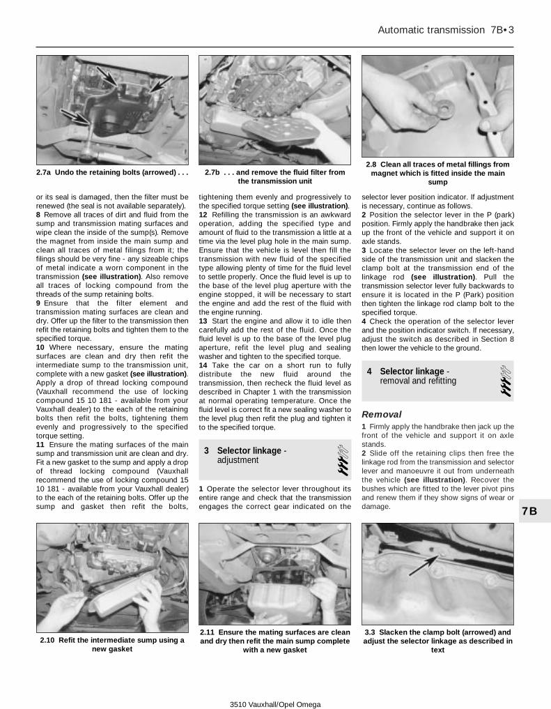
or its seal is damaged, then the filter must berenewed (the seal is not available separately).8 Remove all traces of dirt and fluid from thesump and transmission mating surfaces andwipe clean the inside of the sump(s). Removethe magnet from inside the main sump andclean all traces of metal filings from it; thefilings should be very fine - any sizeable chipsof metal indicate a worn component in thetransmission (see illustration). Also removeall traces of locking compound from thethreads of the sump retaining bolts.9 Ensure that the filter element andtransmission mating surfaces are clean anddry. Offer up the filter to the transmission thenrefit the retaining bolts and tighten them to thespecified torque.10 Where necessary, ensure the matingsurfaces are clean and dry then refit theintermediate sump to the transmission unit,complete with a new gasket (see illustration).Apply a drop of thread locking compound(Vauxhall recommend the use of lockingcompound 15 10 181 - available from yourVauxhall dealer) to the each of the retainingbolts then refit the bolts, tightening themevenly and progressively to the specifiedtorque setting.11 Ensure the mating surfaces of the mainsump and transmission unit are clean and dry.Fit a new gasket to the sump and apply a dropof thread locking compound (Vauxhallrecommend the use of locking compound 1510 181 - available from your Vauxhall dealer)to the each of the retaining bolts. Offer up thesump and gasket then refit the bolts,
tightening them evenly and progressively tothe specified torque setting (see illustration).12 Refilling the transmission is an awkwardoperation, adding the specified type andamount of fluid to the transmission a little at atime via the level plug hole in the main sump.Ensure that the vehicle is level then fill thetransmission with new fluid of the specifiedtype allowing plenty of time for the fluid levelto settle properly. Once the fluid level is up tothe base of the level plug aperture with theengine stopped, it will be necessary to startthe engine and add the rest of the fluid withthe engine running.13 Start the engine and allow it to idle thencarefully add the rest of the fluid. Once thefluid level is up to the base of the level plugaperture, refit the level plug and sealingwasher and tighten to the specified torque.14 Take the car on a short run to fullydistribute the new fluid around thetransmission, then recheck the fluid level asdescribed in Chapter 1 with the transmissionat normal operating temperature. Once thefluid level is correct fit a new sealing washer tothe level plug then refit the plug and tighten itto the specified torque.
3 Selector linkage - adjustment 3
1 Operate the selector lever throughout itsentire range and check that the transmissionengages the correct gear indicated on the
selector lever position indicator. If adjustmentis necessary, continue as follows.2 Position the selector lever in the P (park)position. Firmly apply the handbrake then jackup the front of the vehicle and support it onaxle stands.3 Locate the selector lever on the left-handside of the transmission unit and slacken theclamp bolt at the transmission end of thelinkage rod (see illustration). Pull thetransmission selector lever fully backwards toensure it is located in the P (Park) positionthen tighten the linkage rod clamp bolt to thespecified torque.4 Check the operation of the selector leverand the position indicator switch. If necessary,adjust the switch as described in Section 8then lower the vehicle to the ground.
4 Selector linkage - removal and refitting 3
Removal1 Firmly apply the handbrake then jack up thefront of the vehicle and support it on axlestands.2 Slide off the retaining clips then free thelinkage rod from the transmission and selectorlever and manoeuvre it out from underneaththe vehicle (see illustration). Recover thebushes which are fitted to the lever pivot pinsand renew them if they show signs of wear ordamage.
Automatic transmission 7B•3
7B
2.7a Undo the retaining bolts (arrowed) . . . 2.7b . . . and remove the fluid filter fromthe transmission unit
2.8 Clean all traces of metal fillings frommagnet which is fitted inside the main
sump
2.10 Refit the intermediate sump using anew gasket
2.11 Ensure the mating surfaces are cleanand dry then refit the main sump complete
with a new gasket
3.3 Slacken the clamp bolt (arrowed) andadjust the selector linkage as described in
text
3510 Vauxhall/Opel Omega

Refitting3 Apply a smear of multi-purpose grease tothe linkage rod pivot pins. Ensure the bushesare in position then refit the rod to thetransmission and selector lever and secure itin position with the retaining clips.4 Check the operation of the selector linkageand, if necessary, adjust as described inSection 3 before lower the vehicle to theground.
5 Selector lever assembly -removal and refitting 3
Note: Renewal of the lever switches iscovered in Section 8
RemovalNote: A pop rivet gun and new rivets will berequired on refitting.1 Remove the centre console as described inChapter 11 then position the selector lever inthe P (park) position.2 Firmly apply the handbrake then jack up thefront of the vehicle and support it on axlestands.3 Slide off the retaining clip and detach theselector linkage rod from the base of the lever.Take care not to lose the lever pivot bush.4 Slacken and remove the retaining nuts andbolt then remove the front and rear supportbrackets from the rear heater/ventilation duct.Unclip the duct and remove it from the aroundthe selector lever.5 Disconnect the wiring connector from theselector lever mode switch and unclip thewiring so that it is free to be removed with thelever. On later models were the lever is fittedwith a selector lever pawl, remove the pawlswitch and the ignition key release switch asdescribed in Section 8.6 Carefully drill off the heads from the rivetssecuring the lever mounting plate to the floorthen ease the selector lever out of position.Recover seal (where fitted) which is fittedbetween the housing and floor.7 Inspect the selector lever mechanism forsigns of wear or damage and renew worncomponents as necessary
Refitting8 Ensure the mating surfaces of the levermounting plate and body are clean and dry.Where a seal was fitted between the mountingplate and body ensure the seal is in goodcondition then position it on the body. Whereno seal was fitted apply and thin film ofsealant to the mating surface of the mountingplate to ensure a water-tight seal.9 Manoeuvre the lever assembly into positionand seat it on the body. Locate all the newpop rivets in the mounting plate holes toensure the lever is correct positioned thensecure all the rivets in position with a pop rivetgun.10 Ensure the lever mode switch wiring iscorrectly routed then reconnect its connector.Where necessary, refit the pawl switch andthe ignition key release switch as described inSection 8.11 Clip the rear heater/ventilation duct backinto position then refit the support brackets,tightening their retaining bolt/nuts securely.12 Refit the centre console as described inChapter 11.13 Ensure the pivot bush is correctlypositioned then reconnect the linkage rod tothe transmission selector lever and secure it inposition with the retaining clip.14 Check the operation of the selectorlinkage and, if necessary, adjust as describedin Section 3 before lower the vehicle to theground.
6 Oil seals - renewal 4
Propeller shaft flange oil sealNote: A new flange sealing ring and retainingnut will be required.1 Working as described in Chapter 8, free thefront end of the propeller shaft from thetransmission flange and remove the vibrationdamper (where fitted). If necessary, toimprove access to the flange remove the shaftcompletely.2 To prevent the rotation as the shaft nut isslackened bolt a length of bar with two holesdrilled in it to the flange. Alternatively, a toolcan be fabricated from two lengths of steelstrip (one long, one short) and a nut and bolt;the nut and bolt forming the pivot of a forkedtool.3 Hold the flange then slacken and removethe retaining nut from the end of thetransmission main shaft. Remove the holdingtool and slide off the flange complete with itssealing ring. Discard the nut and sealing ring;new ones should be used on refitting.4 Note the correct fitted depth of the seal inthe transmission housing then carefully prise itout of position using a large flat-bladedscrewdriver.5 Check the propeller flange sealing surface
for signs of wear or damage. If there is visiblesigns of damage, renew the flange.6 Clean all traces of dirt from the area aroundthe oil seal aperture then apply a smear ofgrease to the outer lip of the new oil seal.7 Making sure its sealing lip is facing inwards,slide the new seal over the main shaft end andtap it squarely into position, using a suitabletubular drift (such as a socket) which bearsonly on the hard outer edge of the seal.Ensure the seal is positioned at the samedepth in the housing that the original was.8 Fit the new sealing ring to the flange thenlubricate the seal with a smear of transmissionoil. Carefully slide the propeller flange intoposition, taking care not to damage the seallip. Fit the new nut and tighten it to thespecified torque using the method employedon removal to prevent rotation.9 Reconnect/refit the propeller shaft asdescribed in Chapter 8.10 Take the vehicle on a short run then checkthe transmission fluid level as described inChapter 1.
Selector shaft oil seal11 Remove the selector lever position switchas described in Section 8.12 Using a small flat-bladed screwdriver,carefully lever the oil seal out from the housingthen slide it off of the shaft.13 Clean all traces of dirt from the areaaround the oil seal aperture then apply asmear of grease to the outer edge and lip ofthe new oil seal.14 Making sure its sealing lip is facinginwards, slide the new seal along the selectorshaft and tap it squarely into position, using asuitable tubular drift (such as a socket) whichbears only on the hard outer edge of the seal.15 Refit the selector lever position switch asdescribed in Section 8.
7 Fluid cooler - general information
1 The transmission fluid cooler is an integralpart of the radiator assembly. Refer toChapter 3 for removal and refitting details, ifthe cooler is damaged the complete radiatorassembly must be renewed.
8 Transmission control systemelectrical components -removal and refitting
4Selector lever position switch1 The switch is a multi-function switch,performing the reversing light and starterinhibitor switch functions as well as operatingthe selector lever position indicator panel. If atany time the indicator panel or reversing lightoperation becomes faulty, or it is noted thatthe engine can be started with the selector
7B•4 Automatic transmission
4.2 Slide off the retaining clip (arrowed)and detach the selector linkage rod from
the selector lever
3510 Vauxhall/Opel Omega

lever in any position other than P (park) or N(neutral), then it is likely that the switch isfaulty. If adjustment fails to correct the faultthen the switch assembly must be renewed.
Removal2 Position the selector lever in the N (neutral)position. Firmly apply the handbrake then jackup the rear of the vehicle and support it onaxle stands.3 Referring to Chapter 4A, slacken andremove the bolts securing the front pipe/catalytic converter to the intermediate pipe andseparate the flange joint; on 2.5 and 3.0 litremodels disconnect both left- and right-handsides. Unbolt the heatshield(s) from the vehicleunderbody to gain access to the propeller shaftcentre bearing.4 Slacken and remove the two bolts securingthe propeller shaft centre bearing bracket tothe vehicle body (see Chapter 8). Recover anywashers (where fitted) which are positionedbetween the bracket and vehicle body.5 Trace the wiring back from the switch anddisconnect it at the wiring connector. Unclipthe wiring connector from the side of thetransmission housing so that it is free to beremoved with the switch. If the connectorretaining clip is broken on removal, obtain anew one for refitting.6 Unclip the protective cover from the switchthen unscrew the retaining nut and free theselector lever from the end of the transmissionshaft (see illustrations).7 Place a jack with a block of wood beneaththe transmission, and raise the jack to takethe weight of the transmission.8 With the transmission securely supported,slacken and remove the bolts securing thetransmission unit rear mounting crossmemberto the vehicle body.9 Lower the transmission slightly until accesscan be gained to the switch retaining bolts. Asthe transmission is lowered, take great care toensure excess strain is not placed on thepropeller shaft or any of the enginecomponents and enlist the help of anassistant to make sure nothing becomestrapped between the rear of the engine andbulkhead. Note: On 2.0 litre SOHC engines itmaybe necessary to remove the DIS moduleassembly to gain the necessary clearancerequired (see Chapter 5B).10 Slacken and remove the retaining boltsand slide the switch off of the selector shaft.Whilst the switch is removed check the shaftoil seal for signs of leakage and renew ifnecessary (see Section 6).
Refitting11 Prior to refitting, first make sure that thetransmission selector shaft is still in the N(neutral) position. If there is any doubt, engagethe selector lever with the transmission shaftand move the lever fully backwards (to the Pposition) then move it two notches forwards.12 If a new switch is being fitted, locate theswitch on the shaft then refit the retaining
bolts, tightening them to the specified torque.Note that it is not necessary to adjust theswitch since it is set at the factory and sealedin position; the seal will be broken the firsttime the selector lever is moved.13 If the original switch is being refitting,locate the switch on the transmission shaftthen refit the retaining bolts. Adjust the switchas described in paragraph 21 before tighteningthe retaining bolts to the specified torque.14 Reconnect the selector lever to thetransmission shaft then refit the retaining nut.Tighten the nut to the specified torque settingthen clip the protective cover back onto theswitch.15 Securely reconnect the wiring connectorthen clip the switch connector back onto thetransmission unit and raise the transmissionunit back up into position.16 Remove all traces of locking compoundfrom the transmission unit rear mountingcrossmember to body bolt threads. Apply a fewdrops of thread locking compound (Vauxhallrecommend the use of locking compound15 10 181 - available from your Vauxhall dealer)to the threads of each bolt then refit the boltsand tighten to the specified torque.17 Align the propeller shaft centre bearingbracket with the body making sure anynecessary washers (where fitted) arepositioned between the bracket and body.Refit the bracket retaining bolts and tighten tothe specified torque.18 Referring to Chapter 4A, refit the heat-shields and reconnect the exhaust systemflange joint(s) then lower the vehicle to theground.
AdjustmentNote: Before adjusting the switch first ensurethe selector linkage is correctly adjusted (seeSection 3). A short length of welding rod witha diameter of 2.0 to 2.3 mm will be requiredfor adjustment.19 Position the selector lever in the N(neutral) position. Firmly apply the handbrakethen jack up the rear of the vehicle andsupport it on axle stands.20 Unclip the protective cover from theswitch then unscrew the retaining nut and freethe selector lever from the end of thetransmission shaft.
21 With the transmission in neutral, the slot onthe switch body should be correctly alignedwith the slot on the switch inner ring. Check thisby inserting the welding rod (see illustration). Ifadjustment is necessary, slacken the switchretaining bolts and rotate the switch assemblyas necessary before retightening the bolts tothe specified torque setting.22 Refit the selector lever to the shaft andtighten its retaining nut to the specified torque.23 Clip the protective cover back onto theswitch then lower the vehicle to the ground.
Sport mode switchNote: A soldering iron and solder will berequired to renew the switch.
Removal24 Unclip the selector lever gaiter from thecentre console.25 Push the switch out of the top of theselector lever by inserting a length of weldingrod up through the selector lever bore.26 Make identification marks between theswitch and wires then carefully unsolder thewires from the switch terminals and removethe switch.
Refitting27 Solder the wires to the terminals of theswitch, using the marks made prior to removalto ensure they are correctly connected.
Automatic transmission 7B•5
7B
8.6a Unclip the protective cover from theposition switch . . .
8.6b . . . then slacken and remove theretaining nut (arrowed) and free the
selector lever from the shaft
8.21 Adjusting the selector lever positionswitch
1 Switch retainingbolts
2 Switch grooves3 Welding rod
3510 Vauxhall/Opel Omega
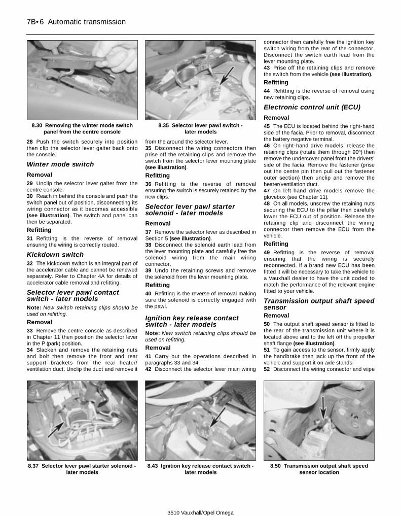
28 Push the switch securely into positionthen clip the selector lever gaiter back ontothe console.
Winter mode switch
Removal29 Unclip the selector lever gaiter from thecentre console.30 Reach in behind the console and push theswitch panel out of position, disconnecting itswiring connector as it becomes accessible(see illustration). The switch and panel canthen be separated.
Refitting31 Refitting is the reverse of removalensuring the wiring is correctly routed.
Kickdown switch32 The kickdown switch is an integral part ofthe accelerator cable and cannot be renewedseparately. Refer to Chapter 4A for details ofaccelerator cable removal and refitting.
Selector lever pawl contactswitch - later modelsNote: New switch retaining clips should beused on refitting.
Removal33 Remove the centre console as describedin Chapter 11 then position the selector leverin the P (park) position.34 Slacken and remove the retaining nutsand bolt then remove the front and rearsupport brackets from the rear heater/ventilation duct. Unclip the duct and remove it
from the around the selector lever.35 Disconnect the wiring connectors thenprise off the retaining clips and remove theswitch from the selector lever mounting plate(see illustration).
Refitting36 Refitting is the reverse of removalensuring the switch is securely retained by thenew clips.
Selector lever pawl startersolenoid - later models
Removal37 Remove the selector lever as described inSection 5 (see illustration).38 Disconnect the solenoid earth lead fromthe lever mounting plate and carefully free thesolenoid wiring from the main wiringconnector.39 Undo the retaining screws and removethe solenoid from the lever mounting plate.
Refitting40 Refitting is the reverse of removal makingsure the solenoid is correctly engaged withthe pawl.
Ignition key release contactswitch - later modelsNote: New switch retaining clips should beused on refitting.
Removal41 Carry out the operations described inparagraphs 33 and 34.42 Disconnect the selector lever main wiring
connector then carefully free the ignition keyswitch wiring from the rear of the connector.Disconnect the switch earth lead from thelever mounting plate.43 Prise off the retaining clips and removethe switch from the vehicle (see illustration).
Refitting44 Refitting is the reverse of removal usingnew retaining clips.
Electronic control unit (ECU)
Removal45 The ECU is located behind the right-handside of the facia. Prior to removal, disconnectthe battery negative terminal.46 On right-hand drive models, release theretaining clips (rotate them through 90º) thenremove the undercover panel from the drivers’side of the facia. Remove the fastener (priseout the centre pin then pull out the fastenerouter section) then unclip and remove theheater/ventilation duct.47 On left-hand drive models remove theglovebox (see Chapter 11).48 On all models, unscrew the retaining nutssecuring the ECU to the pillar then carefullylower the ECU out of position. Release theretaining clip and disconnect the wiringconnector then remove the ECU from thevehicle.
Refitting49 Refitting is the reverse of removalensuring that the wiring is securelyreconnected. If a brand new ECU has beenfitted it will be necessary to take the vehicle toa Vauxhall dealer to have the unit coded tomatch the performance of the relevant enginefitted to your vehicle.
Transmission output shaft speedsensorRemoval50 The output shaft speed sensor is fitted tothe rear of the transmission unit where it islocated above and to the left off the propellershaft flange (see illustration).51 To gain access to the sensor, firmly applythe handbrake then jack up the front of thevehicle and support it on axle stands.52 Disconnect the wiring connector and wipe
7B•6 Automatic transmission
8.30 Removing the winter mode switchpanel from the centre console
8.35 Selector lever pawl switch - later models
8.37 Selector lever pawl starter solenoid -later models
8.43 Ignition key release contact switch -later models
3510 Vauxhall/Opel Omega
8.50 Transmission output shaft speedsensor location

clean the area around the sensor.53 Undo the retaining bolt and remove thesensor from the transmission. Remove thesealing ring from the sensor and discard it, anew one should be used on refitting.
Refitting54 Fit the new sealing ring to the sensorgroove and lubricate it with a smear oftransmission fluid.55 Ease the sensor into position then refit theretaining bolt and tighten it to the specifiedtorque setting. Reconnect the wiringconnector then lower the vehicle to theground.
Transmission solenoid valves56 Removal and refitting of the varioussolenoid valves should be entrusted to aVauxhall dealer.
9 Automatic transmission -removal and refitting 4
Removal1 Chock the rear wheels, apply thehandbrake, and place the selector lever in theN (neutral) position. Jack up the front of thevehicle, and securely support it on axlestands. Undo the retaining screws andremove the undercover from beneath theengine unit. Disconnect the battery negativeterminal. Note: On models with a Vauxhallanti-theft warning system (ATWS), the batterynegative terminal must be disconnected within15 seconds of the ignition being switched offto prevent the alarm system being triggered.2 Working as described in Chapter 8, unboltthe front end of the propeller shaft from thetransmission flange and remove the vibrationdamper (where fitted). Position the propellershaft to the right of the transmission unit andtie it to the vehicle underbody.3 Slide off the retaining clips and detach theselector linkage rod from the transmission unitand selector lever and remove it from thevehicle (see illustration). Take care not tolose the lever pivot bushes.4 Trace the fluid cooler pipes back from thetransmission unit to their flexible hoses.
Remove all traces of dirt then slacken theretaining clips and disconnect both hoses.Minimise fluid loss by folding each hose backon itself and securely connecting it to itsadjacent pipe (see illustrations).5 Disconnect the wiring connector from theoutput shaft speed sensor (see illustration8.50), which is located at the rear of thetransmission unit, and free the wiring from thetransmission unit.
2.0 litre engines6 On SOHC engines, disconnect the wiringconnector from the DIS module (see Chap-ter 5B). Slacken and remove the modulemounting bracket retaining bolts, noting thecorrect fitted location of the engine liftingbracket, then free the wiring harness andremove the module and bracket from the rearof the cylinder head. Free the HT leads fromtheir retaining clips and position the assemblyclear of the transmission unit.7 On all models unclip the oxygen sensorwiring connector from transmission unit anddisconnect it.8 Slacken and remove the exhaust systemfront pipe mounting bracket bolt then removethe bolts securing the front pipe to theintermediate pipe and separate the twoexhaust sections.9 On models with a one-piece engine sump,slacken and remove the bolts securing thesupport brackets to the transmission housingand sides of the cylinder block. Remove bothbrackets from the engine then remove thetorque converter lower cover plate from thebase of the transmission housing.
10 On models with a two-piece engine sump,remove the cover from the sump flange togain access to the torque converter todriveplate bolts.11 Slacken and remove the visible bolt(s) then,using a socket and extension bar to rotate thecrankshaft pulley, undo the remaining boltssecuring the torque converter to the driveplateas they become accessible; there are six boltsin total. If necessary, to prevent rotation as thebolts are slackened, remove the cover from thebase of the torque converter housing and retainthe driveplate by inserting a large screwdriverin through the hole.12 Place a jack with a block of wood beneaththe transmission, and raise the jack to take theweight of the transmission (see illustration).13 With the transmission securely supported,slacken and remove the bolts securing thetransmission unit rear mounting crossmemberto the vehicle body (see illustration).14 Lower the transmission unit slightly anddisconnect the vent hose from the top of thetransmission housing.15 Trace the wiring back from the selectorlever position switch and disconnect it at thewiring connector. Unclip the wiring connectorand position it clear of the transmissionhousing; if the connector retaining clip isbroken on removal, obtain a new one forrefitting.16 Release the retaining clips and disconnectthe wiring connectors from the side of thetransmission main and intermediate housings(see illustration). Release all the wiring fromits retaining clips, noting its correct routing,and position it clear of the transmission unit.
Automatic transmission 7B•7
7B
9.3 Slide off the retaining clip and detachthe selector linkage rod from the
transmission9.4a Release the retaining clips anddisconnect the oil cooler pipes . . .
9.4b . . . then fold them back and connectthem as shown to minimise fluid loss
9.12 Securely support the transmissionunit with a suitable jack . . .
3510 Vauxhall/Opel Omega
9.13 . . . then slacken and remove thebolts securing the transmission unit
crossmember to the body

17 Slacken and remove all the bolts securingthe transmission housing to the engine. Notethe correct fitted positions of each bolt, andthe necessary brackets, as they are removed,to use as a reference on refitting. Make a finalcheck that all components have beendisconnected, and are positioned clear of thetransmission so that they will not hinder theremoval procedure.18 To ensure that the torque converter doesnot fall out as the transmission is removed,slide the converter along the shaft and fullyinto the transmission housing.19 Move the trolley jack and transmission tothe rear, to free it from its locating dowels.Once the transmission is free, carefully lowerthe jack and manoeuvre the unit out fromunder the vehicle. Remove the locatingdowels from the transmission or engine if theyare loose, and keep them in a safe place.
2.5 and 3.0 litre models20 Remove both the exhaust system frontpipes as described in Chapter 4A.21 Remove the cover from the sump flangeto gain access to the torque converterretaining bolts. Slacken and remove thevisible bolt then, using a socket and extensionbar to rotate the crankshaft pulley, undo theremaining bolts securing the torque converterto the driveplate as they become accessible;there are six bolts in total. If necessary, toprevent rotation as the bolts are slackened,remove the cover from the base of the torqueconverter housing and retain the driveplate byinserting a large screwdriver in through thehole (see illustrations).
22 Remove the transmission as described inparagraphs 12 to 19.
Refitting23 The transmission is refitted by a reversalof the removal procedure, bearing in mind thefollowing points.a) If a new transmission unit is being
installed, drain the fluid cooler and blowout the cooler lines using low-pressurecompressed air.
b) Check the torque converter centering pinand the crankshaft bush for signs of wearor damage. Remove all traces of dirt andrust then lubricate the bush a pin with athin smear of molybdenum disulphidegrease (Vauxhall recommend the use oflubricating grease 19 48 568 - availablefrom your Vauxhall dealer).
c) Prior to refitting, ensure that the torqueconverter is correctly engaged with thetransmission by measuring the distancefrom the converter driveplate bolt lugs tothe transmission mating surface. Thisshould be 15 mm (see illustration).
d) Ensure the locating dowels are correctlypositioned and take great care not toallow the weight of the unit to hang on thetorque converter as it is installed. Oncethe transmission and engine are correctlyjoined, refit the securing bolts, tighteningthem to the specified torque setting.
e) Align the torque converter with thedriveplate then refit the retaining boltstightening them lightly only to start thengo around and tighten them to thespecified torque setting in a diagonalsequence.
f) Ensure that the transmission wiring/hosesare correctly routed and retained by allthe necessary clips.
g) Remove all traces of locking compoundfrom the transmission unit rear mountingcrossmember to body bolt threads. Applya few drops of thread locking compound(Vauxhall recommend the use of lockingcompound 15 10 181 - available fromyour Vauxhall dealer) to the threads ofeach bolt prior to refitting and tightenboth bolts to the specified torque.
h) Tighten all nuts and bolts to the specifiedtorque (where given).
i) On completion, refill the transmission withthe specified type and quantity of fluid asdescribed in Section 2 and adjust theselector linkage as described in Section 3.
10 Automatic transmissionoverhaul - general information
51 Overhaul of an automatic transmission unitis beyond the scope of the home mechanicand should be entrusted to a transmissionspecialist.2 In the event of a fault occurring with thetransmission, the vehicle should be taken to asuitably-equipped Vauxhall dealer for testing.A wiring block connector is incorporated inthe electronic control circuit, into which aspecial electronic diagnostic tester can beplugged (see Section 1) and this should locatethe fault.3 Do not remove the transmission from thecar for possible repair before professionalfault diagnosis has been carried out, sincemost tests require the transmission to be inthe vehicle.
7B•8 Automatic transmission
9.16 Disconnect the wiring connectorsfrom the transmission unit and free the
wiring from its retaining clips9.21a Prise out the cover from the sump
flange . . .
9.21b . . . then slacken and remove thetorque converter to driveplate bolts as
described in text
9.21c If necessary, the driveplate can beretained by removing the cover and inserting
a large screwdriver in through the hole
9.23 Check the torque converter is fullyengaged by measuring the distance (X)
from the converter bolt lugs to thetransmission surface. This should be 15 mm
3510 Vauxhall/Opel Omega

3510 Vauxhall/Opel Omega
8•1
8
Chapter 8Final drive, driveshafts and propeller shaft
Final driveType . . . . . . . . . . . . . . . . . . . . . . . . . . . . . . . . . . . . . . . . . . . . . . . . . . . . Unsprung, attached to rear suspension crossmember and underbody.
Limited slip differential optional.Final drive ratio:
Up to 1998 model year:All 2.0 litre 4-cylinder models . . . . . . . . . . . . . . . . . . . . . . . . . . . . . 3.90 : 12.5 litre 6-cylinder models:
Manual transmission . . . . . . . . . . . . . . . . . . . . . . . . . . . . . . . . . . 3.70 : 1Automatic transmission . . . . . . . . . . . . . . . . . . . . . . . . . . . . . . . . 3.90 : 1
3.0 litre 6-cylinder models:Manual transmission . . . . . . . . . . . . . . . . . . . . . . . . . . . . . . . . . . 3.70 : 1Automatic transmission . . . . . . . . . . . . . . . . . . . . . . . . . . . . . . . . 3.70 : 1
From 1998 model year:All 2.0 litre 4-cylinder models . . . . . . . . . . . . . . . . . . . . . . . . . . . . . 3.90 : 12.5 litre 6-cylinder models:
Manual transmission . . . . . . . . . . . . . . . . . . . . . . . . . . . . . . . . . . 3.90 : 1Automatic transmission . . . . . . . . . . . . . . . . . . . . . . . . . . . . . . . . 4.22 : 1
3.0 litre 6-cylinder models:Manual transmission . . . . . . . . . . . . . . . . . . . . . . . . . . . . . . . . . . 3.70 : 1Automatic transmission . . . . . . . . . . . . . . . . . . . . . . . . . . . . . . . . 3.90 : 1
Limited slip differential lock-up value:Typical . . . . . . . . . . . . . . . . . . . . . . . . . . . . . . . . . . . . . . . . . . . . . . . . . 45 %Minimum . . . . . . . . . . . . . . . . . . . . . . . . . . . . . . . . . . . . . . . . . . . . . . . 25 %
DriveshaftType . . . . . . . . . . . . . . . . . . . . . . . . . . . . . . . . . . . . . . . . . . . . . . . . . . . . Maintenance-free double constant velocity joint
Propeller shaftType . . . . . . . . . . . . . . . . . . . . . . . . . . . . . . . . . . . . . . . . . . . . . . . . . . . . Two-piece tubular shaft with centre bearing, centre universal joint, and
flexible disc joint connections to transmission and differential
LubricationFinal drive lubricant capacity . . . . . . . . . . . . . . . . . . . . . . . . . . . . . . . . . 1.0 litreFinal drive lubricant type/specification:
Excluding limited-slip differential:Renewal . . . . . . . . . . . . . . . . . . . . . . . . . . . . . . . . . . . . . . . . . . . . . GM special lubricant 19 42 382 (9 293 688)Top-up . . . . . . . . . . . . . . . . . . . . . . . . . . . . . . . . . . . . . . . . . . . . . . Hypoid gear oil, viscosity SAE 90
Limited-slip differential:Renewal:
First 0.25 litres . . . . . . . . . . . . . . . . . . . . . . . . . . . . . . . . . . . . . . . GM special fluid additive 19 70 452 (90 004 033)Remaining 0.75 litres . . . . . . . . . . . . . . . . . . . . . . . . . . . . . . . . . . GM special lubricant 19 42 382 (9 293 688)
Top-up . . . . . . . . . . . . . . . . . . . . . . . . . . . . . . . . . . . . . . . . . . . . . . GM special lubricant 19 42 382 (9 293 688)Driveshaft CV joint grease type . . . . . . . . . . . . . . . . . . . . . . . . . . . . . . . GM special grease 19 41 522 (90 007 999)
Driveshaft - removal and refitting . . . . . . . . . . . . . . . . . . . . . . . . . . . 8Driveshaft rubber gaiters and outer constant velocity joint - renewal 9Final drive unit - oil level check . . . . . . . . . . . . . . . . . . . . . . . . . . . . . 3Final drive unit - removal and refitting . . . . . . . . . . . . . . . . . . . . . . . . 2Final drive unit damping bracket - renewal . . . . . . . . . . . . . . . . . . . . 4Final drive unit differential bearing oil seal - renewal . . . . . . . . . . . . . 7
Final drive unit pinion oil seal - renewal . . . . . . . . . . . . . . . . . . . . . . . 6Final drive unit rear cover gasket - renewal . . . . . . . . . . . . . . . . . . . . 5General description . . . . . . . . . . . . . . . . . . . . . . . . . . . . . . . . . . . . . . 1Propeller shaft - removal and refitting . . . . . . . . . . . . . . . . . . . . . . . . 10Propeller shaft centre bearing - renewal . . . . . . . . . . . . . . . . . . . . . . 11Propeller shaft disc joints - renewal . . . . . . . . . . . . . . . . . . . . . . . . . 12
Specifications
Contents
Easy, suitable fornovice with littleexperience
Fairly easy, suitablefor beginner withsome experience
Fairly difficult,suitable for competentDIY mechanic
Difficult, suitable forexperienced DIYmechanic
Very difficult,suitable for expert DIYor professional
Degrees of difficulty
54321

Torque wrench settings Nm lbf ftDamping bracket to final drive unit*:
Stage 1 . . . . . . . . . . . . . . . . . . . . . . . . . . . . . . . . . . . . . . . . . . . . . . . . 90 66Stage 2 . . . . . . . . . . . . . . . . . . . . . . . . . . . . . . . . . . . . . . . . . . . . . . . . Tighten a further 45ºStage 3 . . . . . . . . . . . . . . . . . . . . . . . . . . . . . . . . . . . . . . . . . . . . . . . . Tighten a further 15º
Disc joint to propeller shaft transmission or differential:Hexagon bolt . . . . . . . . . . . . . . . . . . . . . . . . . . . . . . . . . . . . . . . . . . . 95 70Torx bolt*:
Stage 1 . . . . . . . . . . . . . . . . . . . . . . . . . . . . . . . . . . . . . . . . . . . . . . 50 37Stage 2 . . . . . . . . . . . . . . . . . . . . . . . . . . . . . . . . . . . . . . . . . . . . . . Tighten a further 75ºStage 3 . . . . . . . . . . . . . . . . . . . . . . . . . . . . . . . . . . . . . . . . . . . . . . Tighten a further 15º
Driveshaft to hub:Stage 1 . . . . . . . . . . . . . . . . . . . . . . . . . . . . . . . . . . . . . . . . . . . . . . . . 50 37Stage 2 . . . . . . . . . . . . . . . . . . . . . . . . . . . . . . . . . . . . . . . . . . . . . . . . Tighten a further 60ºStage 3 . . . . . . . . . . . . . . . . . . . . . . . . . . . . . . . . . . . . . . . . . . . . . . . . Tighten a further 15º
Final drive oil level check plug:Stage 1 . . . . . . . . . . . . . . . . . . . . . . . . . . . . . . . . . . . . . . . . . . . . . . . . 22 16Stage 2 . . . . . . . . . . . . . . . . . . . . . . . . . . . . . . . . . . . . . . . . . . . . . . . . Tighten a further 90ºStage 3 . . . . . . . . . . . . . . . . . . . . . . . . . . . . . . . . . . . . . . . . . . . . . . . . Tighten a further 180º
Final drive unit damping bracket bush to rear crossmember*:Stage 1 . . . . . . . . . . . . . . . . . . . . . . . . . . . . . . . . . . . . . . . . . . . . . . . . 100 74Stage 2 . . . . . . . . . . . . . . . . . . . . . . . . . . . . . . . . . . . . . . . . . . . . . . . . Tighten a further 75ºStage 3 . . . . . . . . . . . . . . . . . . . . . . . . . . . . . . . . . . . . . . . . . . . . . . . . Tighten a further 15º
Final drive unit rear cover . . . . . . . . . . . . . . . . . . . . . . . . . . . . . . . . . . . . 60 44Final drive unit to crossmember*:
Stage 1 . . . . . . . . . . . . . . . . . . . . . . . . . . . . . . . . . . . . . . . . . . . . . . . . 90 66Stage 2 . . . . . . . . . . . . . . . . . . . . . . . . . . . . . . . . . . . . . . . . . . . . . . . . Tighten a further 30ºStage 3 . . . . . . . . . . . . . . . . . . . . . . . . . . . . . . . . . . . . . . . . . . . . . . . . Tighten a further 15º
Propeller shaft centre bearing bracket to underbody . . . . . . . . . . . . . . . 20 15Propeller shaft centre bearing to bracket . . . . . . . . . . . . . . . . . . . . . . . . 22 16Propeller shaft to flexible joint:
Hexagon bolt . . . . . . . . . . . . . . . . . . . . . . . . . . . . . . . . . . . . . . . . . . . 95 70Torx bolt*:
Stage 1 . . . . . . . . . . . . . . . . . . . . . . . . . . . . . . . . . . . . . . . . . . . . . . 50 37Stage 2 . . . . . . . . . . . . . . . . . . . . . . . . . . . . . . . . . . . . . . . . . . . . . . Tighten a further 45º Stage 3 . . . . . . . . . . . . . . . . . . . . . . . . . . . . . . . . . . . . . . . . . . . . . . Tighten a further 15º
Speed sensor to bracket (with ABS) . . . . . . . . . . . . . . . . . . . . . . . . . . . . 4 3*Indicates that a new bolt/nut must be used.
1 General description
1 The final drive unit houses the differentialgears and is bolted directly to the rearsuspension crossmember. The unit has a castaluminium casing which incorporates externalribs to improve structural rigidity and fluidcooling. A bracket with an integral rubberdamping block bolted between the final drivecasing and the suspension crossmembercontrols the movement of the final driveduring operation.2 A limited-slip differential may be fitted as anoption; this incorporates a clutch mechanismwhich controls the difference in speedbetween the left and right hand driveshafts.Under normal conditions, the clutch slipsallowing the driveshafts to rotate at differentspeeds, such as during cornering. When thespeed differential increases beyond a presetlimit, such as during wheelspin caused byrapid acceleration or poor road surfaces, theclutch locks thus preventing the differentialfrom supplying all available drive to thespinning wheel, and ensuring equaldistribution of drive to both rear wheels.
3 Two driveshafts, incorporating Rzeppa-typeconstant velocity joints, transmit drive from thefinal drive differential to the rear wheels. Theinner joints incorporates the Anti-lock BrakingSystem (ABS) rear wheel sensor reluctor discs- see Chapter 9 for details. Flexible rubbergaiters filled with grease encapsulate eachjoint, keeping the joint lubricated andpreventing the ingress of dirt and debris.4 A two-piece, tubular propeller shafttransmits drive from the transmission from tothe final drive unit. It incorporates a centre
bearing supported in a rubber insulator. Therear section of the shaft has a universal joint atits front end, and the front section has a sliderjoint at its rear end. The propeller shaft issecured to the transmission and differential byflexible disc joints.
Final drive identification5 The type of final drive unit fitted can bedetermined by examining the identificationplate affixed to the underside of the final driveunit (see illustration).
2 Final drive unit - removal and refitting 3
Removal1 Chock the front wheels securely. Jack upthe rear of the vehicle, support it on axlestands and remove both rear wheels.2 Remove both driveshafts with reference toSection 8.3 Unhook the exhaust system mountingrubbers and lower the rear of the systemapproximately 300 mm (12.0 in). Support ortie the system in this position.
8•2 Final drive, driveshafts and propeller shaft
3510 Vauxhall/Opel Omega
1.5 Final drive unit identification plate
1 Limited slip differential (0 = yes, 1 = no)
2 Final drive ratio

4 Unbolt the propeller shaft rear flange fromthe flexible drive joint and lever the propellershaft from the joint. Support the propellershaft on an axle stand - do not let it hang bythe universal joint.5 Position a trolley jack underneath the finaldrive unit, and raise it until it just comes intocontact with the underside of the casing.6 Unplug the wiring from both ABS wheelsensors at the connectors.7 Unscrew the bolt securing the dampingbracket at the front of the final drive casing tothe suspension crossmember.8 Unscrew and withdraw the bolt securingthe rear of the final drive casing to thesuspension crossmember.9 Lower the trolley jack and remove the finaldrive from the underside of the vehicle.
Refitting10 Refitting is a reversal of removal, notingthe following points:.a) Check that the distance between the two
final drive bushes on the suspensioncrossmember is between 300 and 302mm. If necessary, adjust this dimensionby altering the position of the bushes inthe crossmember, using a universal pulleror similar tool.
b) Ensure that the wiring for the ABS wheelsensors is securely reconnected.
c) Use new bolts/nuts where indicated (seeSpecifications) and tighten all fixings tothe specified torque.
d) Refit the driveshafts with reference toSection 8.
e) On completion, check the oil level in thefinal drive unit as described in Section 3.
3 Final drive unit - oil level check 2
Level check1 Jack up the front and rear of the vehicleand support it on axle stands so that thevehicle is level.2 Using a hexagon key, unscrew the fillerplug from the right-hand side of the final driveunit. On models with a limited slip differential,it will be necessary to prise the bung from thecentre of the plug first (see illustration).3 Check that the oil level is up to the loweredge of the filler plug aperture using a (clean)piece of bent wire as a dipstick.4 If necessary, top-up with the correct type ofoil as given in the Specifications.5 Refit and tighten the filler plug to thespecified torque, and wipe clean. Refit theplastic bung to the centre of the plug onmodels with a limited slip differential.6 Check the pinion final drive unit oil seal anddifferential bearing oil seals for leaks. Ifevident, renew them.7 Lower the car to the ground.
Complete refill8 Proceed as described for Level checknoting the following points:.a) On models without a limited slip
differential, GM special differential oilmust be used if the final drive is beingrefilled from empty, rather than justtopped-up (see Specifications).
b) On models with a limited slip differential, ifthe final drive is being refilled from empty,rather than just topped-up, the proceduremust be carried out in two stages:
1) Pour 0.25 litres of GM specialdifferential oil additive into the finaldrive
2) Pour approximately 0.75 litres of GMspecial differential oil into the finaldrive, until the level reaches thelower edge of the filler plug aperture(see Specifications).
4 Final drive unit damping bushes -renewal
3Front bush1 Chock the front wheels. Jack up the rear ofthe vehicle and support it on axle stands.2 Support the final drive unit on a trolley jack.3 Unplug the wiring from both ABS wheelsensors at the connectors.4 Slacken and withdraw the bolts securingthe rear of the final drive unit to thesuspension crossmember.5 Fully unscrew the bolt securing thedamping bush bracket to the front of the
suspension crossmember. Lower the finaldrive unit slightly, using the trolley jack.6 Slacken and withdraw the three boltssecuring the damping bracket to the finaldrive unit casing. Be prepared for some oilleakage - position a drip tray underneath thefinal drive casing to catch the oil.7 Detach the damping bush bracket from thefinal drive casing and remove it from thevehicle. Withdraw the securing bolt from thedamper bush.8 Press the old bush from the bracket using ahydraulic press, or drive it out using a suitabledrift. Drive or press the new bush intoposition, ensuring that the recessed section ofthe bush is correctly aligned with the bracketboss (see illustration).9 Commence refitting by inserting thesecuring bolt through the centre of thedamper bush.
Final drive, driveshafts and propeller shaft 8•3
8
3510 Vauxhall/Opel Omega
3.2 Final drive unit oil filler/level plug (A) and plastic bung (B)
4.8 Ensuring that the recessed section ofthe bush is aligned with the bracket boss
as shown

10 Offer the bracket, bush and securing boltup to the final drive casing. Insert the threebracket securing bolts and tighten them to thespecified torque.11 Raise the final drive casing up intoposition using the trolley jack, then tighten thedamper bush-to-suspension crossmemberbolt and tighten it to the specified torque.12 Refit the two rear final drive casing-to-suspension crossmember bolts and tightenthem to the specified torque.13 Reconnect the wiring for the ABS wheelsensors.14 On completion, top-up the differential oilwith reference to Section 3, then lower thevehicle to the ground.
Rear bushes15 Remove the final drive unit as described inSection 2.16 Unbolt the fuel filter from its mountingsand move to one side, with reference toChapter 1. There should be no need todisconnect the fuel lines from it.17 With reference to Chapter 4A, unhook theexhaust system intermediate silencer from itsmountings and support it on axle stand.18 Extract the bushes from the suspensioncrossmember using a universal puller orsimilar tool. The bushes are removed from theoutside of the crossmember.19 Press the new bushes into thecrossmember, ensuring that the distancemeasured between their inner edges isbetween 300 and 302 mm (see illustration).20 Refit the final drive unit as described inSection 2.21 Refit the fuel filter and exhaust systemsilencer as described in Chapters 1 and 4Arespectively.
5 Final drive unit rear cover gasket -renewal
31 Remove the final drive unit as described inSection 2.2 Place the final drive unit in a suitable driptray, then unbolt and remove the rear coverfrom the casing. Remove the gasket and allowthe oil to drain.3 Thoroughly clean the joint faces of the finaldrive casing and cover.4 Apply a coat of the recommended sealantto the mating surface of the final drive casing.5 Refit the cover, then insert and tighten thebolts progressively to the specified torque. Itis recommended that new bolts are used.6 Refit the final drive unit to the vehicle asdescribed in Section 2.7 Lower the vehicle to the ground. Oncompletion, refill the final drive unit with thespecified quantity and grade(s) of oil, asdescribed in Section 3.
6 Final drive unit pinion oil seal- renewal 3
Caution: The pinion bearing pre-load willbe affected by the renewal of the pinion oilseal and must be reset accuratelyfollowing repair work. The followingprocedure describes how to reset thebearing pre-load approximately, usingrudimentary tools, but we recommend thatthe pre-load is set accurately by a Vauxhalldealer, or an engineering workshop.1 Remove the final drive unit as described inSection 2.
2 Mount the unit in a vice.3 Measure the pinion bearing pre-load asfollows: fit a socket on the pinion nut, andusing an adjustable low-torque wrench,measure the torque which must be applied tocause pinion to just start to rotate - the figureshould be approximately 90 to 120 Ncm.Record this figure for later reference.4 Mark the drive flange nut in relation to thedrive flange and pinion.5 Hold the drive flange stationary by bolting alength of metal bar to it, then unscrew the nutnoting the exact number of turns necessary toremove it.6 Using a suitable puller, draw the driveflange from the pinion.7 Lever the oil seal from the final drive casingwith a screwdriver. Wipe clean the oil sealseating.8 Smear a little differential oil (seeSpecifications) on the sealing lip of the new oilseal, then drive it squarely into the casing untilflush with the outer face. Ideally use metaltubing to fit the oil seal, but alternatively ablock of wood may be used on each side ofthe pinion.9 Locate the drive flange on the pinion in itsoriginal position, then refit the nut to itsoriginal position, using the markings andnotes made during removal.10 The pinion drive bearing pre-load mustnow be reset to its original value. Measure thetorque required to turn the pinion, asdescribed in paragraph 3. Adjust the positionof the pinion nut until the measured value isthe same as that recorded earlier.11 Refit the final drive unit with reference toSection 2.
7 Final drive unit differential bearing oil seal -renewal
31 Chock the front wheels. Jack up the rear ofthe vehicle and support it on axle stands.Remove the appropriate rear wheel.2 Remove the appropriate driveshaft withreference to Section 8.3 Note the fitted depth of the oil seal in thefinal drive casing.4 Using a screwdriver or hooked instrument,lever out the oil seal (see illustration), taking
8•4 Final drive, driveshafts and propeller shaft
3510 Vauxhall/Opel Omega
4.19 Press the new bushes into the crossmember, ensuring that the distance measuredbetween their inner edges (I) is between 300 and 302 mm
7.4 Differential bearing oil seal

great care avoid damaging the surface of theseal housing. Wipe the oil from the oil sealhousing.5 Smear a little oil on the sealing lip of thenew oil seal. Using suitable metal tubing drivethe oil seal squarely into the casing to thepreviously noted position.6 Refit the driveshaft with reference toSection 8.7 Refit the wheel and lower the vehicle to theground.
8 Driveshaft -removal and refitting 3
Removal1 Chock the front wheels, then jack up therear of the vehicle and support it on axlestands.2 Unscrew the socket-head bolts securingthe driveshaft to the rear hub while holding therear wheel stationary. Recover the lock-washers.3 Lever the driveshaft from the rear hub andsupport it above the disc brake assembly.4 Remove the rear wheel.5 Position a container under the final driveunit to catch any spilled oil.6 Carefully lever the driveshaft from the finaldrive unit differential. On models withanti-lock braking take care not to damage thewheel speed sensor and reluctor wheel.7 Withdraw the driveshaft from the side of thevehicle.8 Check the circlip on the inner end of thedriveshaft and if necessary renew it.
Refitting9 Refitting is a reversal of removal, but makesure that the driveshaft is fully entered in thedifferential side gear with the circlip engagedin its groove. Tighten the mounting bolts inthree stages, as detailed in the Specifications(see illustrations). Check and if necessarytop up the oil level in the final drive unit, asdescribed in Section 3.
9 Driveshaft rubber gaitersand outer constant velocityjoint - renewal
31 Remove the driveshaft as described inSection 8 and mount it in a vice.2 Using a small drift, tap the metal cover fromthe outer joint.3 Loosen and remove both clips from therubber bellows.4 Using a sharp knife slice through the rubberbellows and remove them from the driveshaft.5 Scoop out the grease from the joint andwipe the driveshaft clean.6 Using circlip pliers, extract the circlip fromthe outer end of the driveshaft.7 Support the outer joint on a vice, then tapthe driveshaft down through it.8 Fill the inner joint with the specified type ofgrease using a wooden spatula.9 Fit the new inner bellows, check that it isnot twisted then fit and tighten the clips.10 Locate the outer bellows on the drive-shaft.11 Fit the outer joint, using a tubular metaldrift, with the driveshaft mounted in a vice.Make sure that the joint abuts the shoulder.12 Fit the circlip making sure that it fullyenters the groove.13 Using the wooden spatula fill the outerjoint with grease.14 Locate the outer bellows on the plate,check that it is not twisted then fit and tightenthe clips.
15 Locate the cover on the joint using twodriveshaft bolts to ensure correct alignment.Tap the cover on the joint with a soft-facedmallet.16 Extract the retaining circlip from the innerend of the driveshaft and fit a new one.17 Refit the driveshaft with reference toSection 8.
10 Propeller shaft -removal and refitting 3
Removal1 Chock the front wheels. Jack up the rear ofthe vehicle and support it on axle stands.2 On models equipped with a catalyticconverter, from underneath the vehicle, undothe retaining bolts and remove both the largeand small catalytic converter heatshields fromthe vehicle underbody (see illustration).3 At the sliding joint, mark the relationshipbetween the front and rear sections of thepropeller shaft. If the two halves of the shaftbecome separated during removal, reconnectthem using the alignment markings, topreserve the balance characteristics.4 Using a conventional, or Torx, socket asapplicable, unscrew the bolts securing thefront flexible disc joint to the transmissionoutput flange (see illustration).5 At the rear of the propeller shaft, unscrewthe bolts securing the rear disc joint to thedifferential flange (see illustration).
Final drive, driveshafts and propeller shaft 8•5
8
8.9a Tighten the driveshaft mounting boltsto the specified first stage torque . . .
8.9b . . . then angle tighten to the specifiedsecond and third stages
10.2 Remove the exhaust heat shieldsfrom the vehicle underbody
10.4 Unscrew the bolts (arrowed) securingthe front flexible disc joint to the
transmission output flange
10.5 Unscrew the bolts (arrowed) securingthe rear disc joint to the differential flange
3510 Vauxhall/Opel Omega

6 Support the centre of the propeller shaft onan axle stand, then unbolt the centre bearingsupport bracket from the underbody, notingthe location of any alignment shims (seeillustration).7 Push the front section rearwards along theslider joint splines until clear of thetransmission output flange.8 Withdraw the propeller shaft forwards,making sure that the front section remains onthe slider joint splines (see paragraph 3).9 Unbolt the centre support bracket from thecentre bearing, noting the location of anyalignment shims.10 Unbolt the front and rear disc joints fromthe propeller shaft. Note that on some modelsa vibration damper is fitted at the front of thepropeller shaft.
Refitting11 Refitting is a reversal of removal, notingthe following points:.a) Coat the inboard splines of the driveshaft
with differential oil before inserting theminto the final drive.
b) Tighten all nuts and bolts to the specifiedtorque.
11 Propeller shaft centre bearing -renewal
31 Remove the propeller shaft as described inSection 10.2 Mount the rear propeller shaft section in avice, using shaped blocks of wood to preventdamage.3 Mark the front and rear sections in relationto each other, then pull the front section fromthe splines.4 Slide off the rubber sleeve, then usingcirclip pliers, extract the circlip from thegroove in front of the centre bearing (seeillustration). Extract the dust seal washer.5 Unbolt the centre bearing from its mountingbracket.6 Support the centre bearing on a vice, andpress or drive the rear propeller shaft sectiondown through the bearing. Recover the dustseal washer.7 Similarly, press or drive the ball bearingfrom the centre bearing housing, and removethe dust cover.8 Clean the removed components and theend of the propeller shaft. Lightly grease thesplines.9 Press or drive the new ball bearing into thehousing, and align the dust washer.10 Support the rear section universal joint ona vice, and press or drive the centre bearingover the splines using a metal tube on theinner track. Make sure that the bearing makescontact with its seating shoulder.11 Bolt the mounting bracket to the centrebearing and tighten the bolts to the specifiedtorque.12 Mount the rear section in a vice, and fitthe front dust washer and the circlip, makingsure that it is correctly located in the groove.13 Locate the rubber sleeve over the splines.14 Fit the front section on the rear section
splines, making sure that the previously-mademarks are aligned, to preserve the balancecharacteristics. Note that a master spline isprovided to ensure correct assembly (seeillustration).15 Refit the propeller shaft as described inSection 10.
12 Propeller shaft disc joints -renewal 3
1 Chock the front wheels. Jack up the rear ofthe vehicle and support it on axle stands.2 Apply the handbrake, then whereapplicable, unbolt and remove the heatshieldsfrom the vehicle underbody to gain access tothe disc joints.3 If removing the rear disc joint, unbolt thepropeller shaft centre bearing mountingbracket from the underside of the vehicle andsupport the propeller shaft on an axle stand.4 Unbolt the propeller shaft flange(s) from theflexible disc joint(s).5 Unbolt the flexible disc joint from thetransmission and/or differential drive flange(s).6 Push the appropriate propeller shaft sectiontowards the centre bearing and remove thedisc joint(s). If necessary, use a lever to prisethe propeller shaft clear of the drive flange(s).7 Fit the new flexible disc joint(s) using areversal of the removal procedure, noting thefollowing points:.a) Bolt the disc joint to the propeller first, then
to the transmission/final drive flange. b) Tighten all nuts and bolts to the specified
torque (see Specifications).c) Where applicable, refit the propeller shaft
centre bearing mounting bracket to theunderside of the vehicle as described inSection 11.
d) Securely refit all heatshield panelsremoved for access.
8•6 Final drive, driveshafts and propeller shaft
10.6 Centre bearing support bracket bolts(arrowed)
3510 Vauxhall/Opel Omega
11.4 Extract the circlip from the groove in front of the centre bearing
11.14 Note that a master spline (arrowed) is provided to ensurecorrect assembly
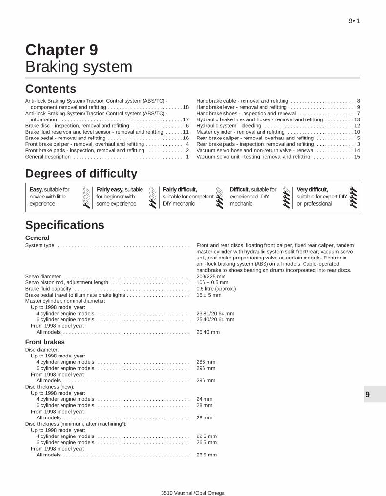
3510 Vauxhall/Opel Omega
9•1
9
Chapter 9Braking system
GeneralSystem type . . . . . . . . . . . . . . . . . . . . . . . . . . . . . . . . . . . . . . . . . . . . . . Front and rear discs, floating front caliper, fixed rear caliper, tandem
master cylinder with hydraulic system split front/rear, vacuum servounit, rear brake proportioning valve on certain models. Electronicanti-lock braking system (ABS) on all models. Cable-operatedhandbrake to shoes bearing on drums incorporated into rear discs.
Servo diameter . . . . . . . . . . . . . . . . . . . . . . . . . . . . . . . . . . . . . . . . . . . . 200/225 mmServo piston rod, adjustment length . . . . . . . . . . . . . . . . . . . . . . . . . . . 106 + 0.5 mmBrake fluid capacity . . . . . . . . . . . . . . . . . . . . . . . . . . . . . . . . . . . . . . . . 0.5 litre (approx.)Brake pedal travel to illuminate brake lights . . . . . . . . . . . . . . . . . . . . . . 15 ± 5 mmMaster cylinder, nominal diameter:
Up to 1998 model year:4 cylinder engine models . . . . . . . . . . . . . . . . . . . . . . . . . . . . . . . . 23.81/20.64 mm6 cylinder engine models . . . . . . . . . . . . . . . . . . . . . . . . . . . . . . . . 25.40/20.64 mm
From 1998 model year:All models . . . . . . . . . . . . . . . . . . . . . . . . . . . . . . . . . . . . . . . . . . . . 25.40 mm
Front brakesDisc diameter:
Up to 1998 model year:4 cylinder engine models . . . . . . . . . . . . . . . . . . . . . . . . . . . . . . . . 286 mm6 cylinder engine models . . . . . . . . . . . . . . . . . . . . . . . . . . . . . . . . 296 mm
From 1998 model year:All models . . . . . . . . . . . . . . . . . . . . . . . . . . . . . . . . . . . . . . . . . . . . 296 mm
Disc thickness (new):Up to 1998 model year:
4 cylinder engine models . . . . . . . . . . . . . . . . . . . . . . . . . . . . . . . . 24 mm6 cylinder engine models . . . . . . . . . . . . . . . . . . . . . . . . . . . . . . . . 28 mm
From 1998 model year:All models . . . . . . . . . . . . . . . . . . . . . . . . . . . . . . . . . . . . . . . . . . . . 28 mm
Disc thickness (minimum, after machining*):Up to 1998 model year:
4 cylinder engine models . . . . . . . . . . . . . . . . . . . . . . . . . . . . . . . . 22.5 mm6 cylinder engine models . . . . . . . . . . . . . . . . . . . . . . . . . . . . . . . . 26.5 mm
From 1998 model year:All models . . . . . . . . . . . . . . . . . . . . . . . . . . . . . . . . . . . . . . . . . . . . 26.5 mm
Anti-lock Braking System/Traction Control system (ABS/TC) -component removal and refitting . . . . . . . . . . . . . . . . . . . . . . . . . . 18
Anti-lock Braking System/Traction Control system (ABS/TC) -information . . . . . . . . . . . . . . . . . . . . . . . . . . . . . . . . . . . . . . . . . . . 17
Brake disc - inspection, removal and refitting . . . . . . . . . . . . . . . . . . 6Brake fluid reservoir and level sensor - removal and refitting . . . . . . 11Brake pedal - removal and refitting . . . . . . . . . . . . . . . . . . . . . . . . . . 16Front brake caliper - removal, overhaul and refitting . . . . . . . . . . . . . 4Front brake pads - inspection, removal and refitting . . . . . . . . . . . . 2General description . . . . . . . . . . . . . . . . . . . . . . . . . . . . . . . . . . . . . . 1
Handbrake cable - removal and refitting . . . . . . . . . . . . . . . . . . . . . . 8Handbrake lever - removal and refitting . . . . . . . . . . . . . . . . . . . . . . 9Handbrake shoes - inspection and renewal . . . . . . . . . . . . . . . . . . . 7Hydraulic brake lines and hoses - removal and refitting . . . . . . . . . . 13Hydraulic system - bleeding . . . . . . . . . . . . . . . . . . . . . . . . . . . . . . . 12Master cylinder - removal and refitting . . . . . . . . . . . . . . . . . . . . . . . 10Rear brake caliper - removal, overhaul and refitting . . . . . . . . . . . . . 5Rear brake pads - inspection, removal and refitting . . . . . . . . . . . . . 3Vacuum servo hose and non-return valve - renewal . . . . . . . . . . . . . 14Vacuum servo unit - testing, removal and refitting . . . . . . . . . . . . . . 15
Specifications
Contents
Easy, suitable fornovice with littleexperience
Fairly easy, suitablefor beginner withsome experience
Fairly difficult,suitable for competentDIY mechanic
Difficult, suitable forexperienced DIYmechanic
Very difficult,suitable for expert DIYor professional
Degrees of difficulty
54321

Front brakes (continued)Disc thickness (minimum, wear limit):
Up to 1998 model year:4 cylinder engine models . . . . . . . . . . . . . . . . . . . . . . . . . . . . . . . . 21 mm6 cylinder engine models . . . . . . . . . . . . . . . . . . . . . . . . . . . . . . . . 25 mm
From 1998 model year:All models . . . . . . . . . . . . . . . . . . . . . . . . . . . . . . . . . . . . . . . . . . . . 25 mm
Disc maximum thickness variation . . . . . . . . . . . . . . . . . . . . . . . . . . . . . 0.01 mmDisc maximum run-out . . . . . . . . . . . . . . . . . . . . . . . . . . . . . . . . . . . . . . 0.12 mmDisc maximum score depth . . . . . . . . . . . . . . . . . . . . . . . . . . . . . . . . . . 0.4 mmBrake pad thickness (including backplate):
New . . . . . . . . . . . . . . . . . . . . . . . . . . . . . . . . . . . . . . . . . . . . . . . . . . . 17.5 ± 0.6 mmMinimum . . . . . . . . . . . . . . . . . . . . . . . . . . . . . . . . . . . . . . . . . . . . . . . 8.0 mm
Caliper piston diameter:Up to 1998 model year:
4 cylinder engine models . . . . . . . . . . . . . . . . . . . . . . . . . . . . . . . . 54 mm6 cylinder engine models . . . . . . . . . . . . . . . . . . . . . . . . . . . . . . . . 54 mm
From 1998 model year:All models . . . . . . . . . . . . . . . . . . . . . . . . . . . . . . . . . . . . . . . . . . . . 57 mm
*After machining the disc surface, new brake pads must be fitted. Once these are worn, no more new pads may be used with the same discs -new discs must then be fitted.
Rear brakesDiscs diameter (new) . . . . . . . . . . . . . . . . . . . . . . . . . . . . . . . . . . . . . . . 286 mmDisc thickness:
New . . . . . . . . . . . . . . . . . . . . . . . . . . . . . . . . . . . . . . . . . . . . . . . . . . . 12.0 mmMinimum (after machining*) . . . . . . . . . . . . . . . . . . . . . . . . . . . . . . . . 11.0 mmMinimum (wear limit) . . . . . . . . . . . . . . . . . . . . . . . . . . . . . . . . . . . . . . 10.0 mmVariation (maximum) . . . . . . . . . . . . . . . . . . . . . . . . . . . . . . . . . . . . . . 0.01 mmRun-out (maximum) . . . . . . . . . . . . . . . . . . . . . . . . . . . . . . . . . . . . . . 0.12 mm
Caliper piston diameter . . . . . . . . . . . . . . . . . . . . . . . . . . . . . . . . . . . . . 40.0 mmBrake pad thickness (including backplate):
New . . . . . . . . . . . . . . . . . . . . . . . . . . . . . . . . . . . . . . . . . . . . . . . . . . . 17.0 mmMinimum . . . . . . . . . . . . . . . . . . . . . . . . . . . . . . . . . . . . . . . . . . . . . . . 6.0 mm
Handbrake shoe minimum thickness (lining only) . . . . . . . . . . . . . . . . . 1.0 mmHandbrake drum diameter:
New . . . . . . . . . . . . . . . . . . . . . . . . . . . . . . . . . . . . . . . . . . . . . . . . . . . 160.0 mmMaximum (wear limit**) . . . . . . . . . . . . . . . . . . . . . . . . . . . . . . . . . . . . 161.0 mm
*After machining the disc surface, new brake pads must be fitted. Once these are worn, no more new pads may be used with the same discs -new discs must then be fitted.**After machining the drum surface, new brake shoes must be fitted. Once these are worn, no more new shoes may be used with the same drums- new drums must then be fitted.
Torque wrench settings Nm lbf ftABS control unit bracket to modulator . . . . . . . . . . . . . . . . . . . . . . . . . . 8 6ABS modulator to bodywork . . . . . . . . . . . . . . . . . . . . . . . . . . . . . . . . . 10 7ABS modulator-to-bracket nuts . . . . . . . . . . . . . . . . . . . . . . . . . . . . . . . 8 6ABS wheel sensor securing screws . . . . . . . . . . . . . . . . . . . . . . . . . . . . 8 6Brake disc locking screw . . . . . . . . . . . . . . . . . . . . . . . . . . . . . . . . . . . . 4 3Brake line union nuts/bolts . . . . . . . . . . . . . . . . . . . . . . . . . . . . . . . . . . . 16 12Brake pedal bracket to bulkhead . . . . . . . . . . . . . . . . . . . . . . . . . . . . . . 20 15Brake pedal shaft to bracket . . . . . . . . . . . . . . . . . . . . . . . . . . . . . . . . . 18 13Caliper bleed screw . . . . . . . . . . . . . . . . . . . . . . . . . . . . . . . . . . . . . . . . 9 7Caliper brake hose union bolt . . . . . . . . . . . . . . . . . . . . . . . . . . . . . . . . . 40 30Caliper guide bolt . . . . . . . . . . . . . . . . . . . . . . . . . . . . . . . . . . . . . . . . . . 30 22Front caliper mounting bracket-to-steering knuckle bolts (all calipers)*:
Stage 1 . . . . . . . . . . . . . . . . . . . . . . . . . . . . . . . . . . . . . . . . . . . . . . . . 95 70Stage 2 . . . . . . . . . . . . . . . . . . . . . . . . . . . . . . . . . . . . . . . . . . . . . . . . Angle-tighten through 30º to 45º
Handbrake lever . . . . . . . . . . . . . . . . . . . . . . . . . . . . . . . . . . . . . . . . . . . 20 15Master cylinder front mounting . . . . . . . . . . . . . . . . . . . . . . . . . . . . . . . . 22 16Master cylinder to vacuum servo . . . . . . . . . . . . . . . . . . . . . . . . . . . . . . 22 16Rear caliper mounting bolts . . . . . . . . . . . . . . . . . . . . . . . . . . . . . . . . . . 80 59Road wheel bolts . . . . . . . . . . . . . . . . . . . . . . . . . . . . . . . . . . . . . . . . . . 110 81Vacuum servo . . . . . . . . . . . . . . . . . . . . . . . . . . . . . . . . . . . . . . . . . . . . . 21 15*Use new bolts.Note: The threads of all fasteners secured with locking compound must be thoroughly cleaned and, if necessary, re-cut to remove all traces of theold locking compound. Fresh locking compound should then be reapplied at reassembly.
9•2 Braking system
3510 Vauxhall/Opel Omega

1 General description
1 The braking system is of dual hydrauliccircuit type with front and rear discs. The frontand rear hydraulic circuits are operatedindependently, so that in the event of a failurein one circuit the remaining circuit stillfunctions. The floor-mounted handbrake leveroperates brake shoes by means of a cable.The handbrake shoes are mounted inside therear brake discs; the inner surface of each rearbrake disc incorporates a brake drum. Thedisc brakes are self-adjusting in use, howeverthe handbrake is adjusted manually.2 An Anti-lock Braking System (ABS) is fittedas standard equipment on all models. Pre-1998 models have 3-channnel ABS, withindependent hydraulic circuits for each frontbrake, and a shared hydraulic circuit for therear brakes. Later models have 4-channel ABS,with independent circuits for all four brakes.3 During braking, the ABS system adjusts thebraking system hydraulic pressure, to preventthe road wheels from locking, therebyreducing the likelihood of skidding in slipperyconditions and/or during heavy braking. Thesystem incorporates an electronic control unitwhich is supplied with signals from the wheelspeed sensors. The signals are compared witheach other and, if one wheel is found to bedecelerating more rapidly than the others, thehydraulic pressure to that wheel is reduceduntil its speed matches the other wheels. TheABS unit is fitted in the hydraulic lines leadingfrom the master cylinder to the brakes, thevacuum servo unit and master cylinder beingof similar type for both non-ABS and ABSmodels. The ABS control system alsomanages the operation of the Traction Control(TC) system fitted to models with 6-cylinderengines. For more details of the ABS/TCsystems, refer to Sections 17 and 18.4 Should the ABS develop a fault, it isrecommended that a complete system checkis carried out by a GM dealer or ABS specialist,who will have access to the specialistequipment necessary to make an accuratediagnosis of the problem.
2 Front brake pads -inspection, removal and refitting
3Warning: Renew both sets of frontbrake pads at the same time -never renew the pads on only one
wheel, as uneven braking may result. Notethat the dust created by wear of the padsmay contain asbestos, which is a healthhazard. Never blow it out with compressedair, and don’t inhale any of it. An approvedfiltering mask should be worn whenworking on the brakes. DO NOT usepetroleum-based solvents to clean brakeparts - use brake cleaner or methylatedspirit only.
Removal1 Apply the handbrake. Jack up the front ofthe vehicle and support it on axle stands.Remove the front wheels.2 Turn the steering to full right-hand lock andcheck the wear of the linings on theright-hand brake pads through the inspectionaperture at the front of the caliper body.Check that the thickness of the liningincluding the backing plate is as shown in theSpecifications using a steel rule or verniercalipers.3 Turn the steering to full left-hand lock andcheck the left-hand brake pads in the sameway.
4 If any brake pad is worn below theminimum thickness, renew all the front padsas a set together with new anti-rattle springs,as described in the following paragraphs.5 Using a small flat bladed screwdriver,unclip the pad wear sensor from the caliperaperture, and position it clear of the work area(see illustration).6 Slide out the metal retaining clip andrelease the brake hose from its supportbracket at the side of the suspension strut(see illustration).
4-cylinder engined models up to 19987 Remove the large spring clip from the sideof the brake caliper (see illustration). The clipis under relatively high tension and may fly offwith some force when released; to preventinjury, cover the spring with a large rag beforeprising it from the caliper with a stoutscrewdriver.8 Remove the dust caps from the caliperguide pin bolt holes, then slacken and removethe two guide pin bolts (see illustrations),and withdraw them from the caliper.9 Withdraw the caliper from its mountingbracket, then tie the caliper to the suspensionstrut, using a suitable piece of wire (seeillustration).
Warning: Take great care to avoidkinking or placing any strain onthe flexible brake hose.
10 Remove the outer pad from the calipermounting bracket.
Braking system 9•3
9
2.7 Remove the large spring clip from theside of the brake caliper
2.8a Remove the dust caps . . . 2.8b . . . then slacken and remove the twoguide pin bolts
2.5 Unclip the pad wear sensor from thecaliper aperture
2.6 Slide out the metal retaining clip andrelease the brake hose from the
suspension strut
3510 Vauxhall/Opel Omega

11 Carefully prise the inner pad from thecaliper piston, which is retained by metalspring clip attached to the rear of the padbacking plate (see illustration).
4-cylinder engined models from 1998and all 6-cylinder engined models12 Remove the dust caps from the caliperlower guide pin bolt hole, then slacken thelower guide pin bolt, and withdraw it from thecaliper. Counterhold the guide pin with asecond spanner (see illustrations).13 Pivot the caliper upwards (seeillustration), to expose the brake disc andpads. Suspend the caliper in the verticalposition, using a suitable piece of wire.
Warning: Take great care to avoidkinking or placing any strain onthe flexible brake hose.
14 Remove both brake pads from the caliperbracket (see illustrations).
Inspection15 First measure the thickness of each brakepad (friction material and backing plate) (seeillustration). If either pad is worn at any pointto the specified minimum thickness (seeSpecifications), all four front brake pads mustbe renewed, so that even braking balance ismaintained. The pads should also be renewedif any are fouled with oil or grease; there is nosatisfactory way of degreasing frictionmaterial, once it is contaminated. If any of thebrake pads are worn unevenly or fouled withoil or grease, trace and rectify the causebefore reassembly. If the pad wear sensor hasbeen in contact with the brake disc (causingthe brake pad warning light to illuminate), thatmust also be renewed.16 Inspect the brake disc with reference tothe information given in Section 6.17 If the brake pads are still serviceable,
carefully clean them using a clean, fine wirebrush or similar, paying particular attention tothe sides and back of the metal backing.Clean out the grooves in the friction material(where applicable), and pick out any largeembedded particles of dirt or debris. Carefullyclean the pad locations in the caliper bodyand mounting bracket. Check that the guidepins are free to slide easily in the calipermounting bushes. Brush the dust and dirtfrom the caliper and piston, but do not inhaleit, as it is injurious to health. Inspect the dustseal around the piston for damage, and thepiston for evidence of fluid leaks, corrosion ordamage. If attention to any of thesecomponents is necessary, refer to theinformation given in the following sub-section.18 If new brake pads are being fitted, thecaliper piston must be pushed back into thecylinder to make room for the greater depth offriction material. Either use a G-clamp orsimilar tool, or use suitable pieces of wood aslevers (see illustration). Provided that themaster cylinder reservoir has not beenoverfilled with hydraulic fluid, there should beno spillage, but keep a careful watch on thefluid level while retracting the piston. If thefluid level rises above the maximum levelmark, the surplus should be siphoned offusing a syringe, or ejected via a plastic tubeconnected to the bleed screw, to avoidoverflow, before retracting the piston anyfurther.19 Prior to fitting the pads, check that theguide bolts are a snug fit in the caliperbushes. Remove any remaining dust and dirt
9•4 Braking system
2.9 Remove the caliper from its mountingbrackets
2.11 Carefully prise the inner pad from thecaliper piston
2.12a Slacken the lower guide pin bolt,counterholding the guide pin with a
second spanner . . .
2.14a Remove the outer . . . 2.14b . . . and inner brake pads from thecaliper bracket
2.15 Measuring the thickness of a brake pad
2.12b . . . and withdraw the guide pin boltfrom the caliper
2.13 Pivot the caliper upwards to exposethe brake pads
3510 Vauxhall/Opel Omega

from the caliper, piston and caliper mountingbracket using a stiff brush and proprietarybrake component cleaning fluid - the use ofother solvents or cleaning agents may causedamage to the caliper rubber seals. Apply alittle high-melting-point copper brake greaseto the areas on the pad backing plates andcaliper mounting bracket which contact thecaliper and piston (see illustrations).Caution: Take great care to avoidcontaminating the pad friction materialand brake disc surface.Inspect the dust seal around the piston fordamage, and the piston for evidence of fluidleaks, corrosion or damage. If attention to anyof these components is necessary, refer tofront brake caliper overhaul information inSection 4.
Refitting
4-cylinder engined models up to 199820 Fit the inner brake pad to the caliper bypressing the spring clip on the pad backingplate into the piston. Check that the butterflyspring at the edge of the pad bears on theinside of the caliper and is not jammed in thecaliper inspection aperture.21 Place the outer pad in the calipermounting bracket, with the friction materialfacing the disc, and check that it slides freelyalong its guides towards the brake disc.22 Fit the brake caliper and outer pad overthe disc, ensuring that the outer edge of thecaliper bears squarely on the rear of the outerbrake pad’s backing plate. Check that thebutterfly spring at the edge of the pad bearson the inside of the caliper and is not jammedin the caliper inspection aperture.23 Thoroughly clean the threads of thecaliper guide pin bolts, fit them to the caliperand then tighten them to the specified torque.Refit the dust covers.24 Refit the caliper spring, ensuring that itsends are firmly pressed into the holes in theside of the caliper body (see illustration).
4-cylinder engined models from 1998and all 6-cylinder engined models25 Fit the inner and outer brake pads to thecaliper mounting bracket ensuring that thefriction material is facing the surface of the
brake disc. Check that the pads slide easilyalong their guides towards the brake disc.26 Pivot the caliper body down over thepads, ensuring that caliper piston bearsagainst the rear of the inner pad’s backingplate and that the outer edge of the caliperbears against the rear of the outer pad’sbacking plate. Check that the butterfly springsat the edge of the pad bear on the inside ofthe caliper and are not jammed in the caliperinspection aperture.27 Thoroughly clean the threads of thecaliper lower guide pin bolt, fit it to the caliperand then tighten it to the specified torque.Refit the dust cover.
All models28 Clip the pad wear sensor into position onthe inner brake pad. If a new sensor is beinginstalled, trace the wiring of the originalsensor back to the connector, thendisconnect it and remove the old sensor fromthe vehicle. Connect the wiring connector ofthe new sensor, ensuring that the wiring iscorrectly routed and retained by all thenecessary clips.29 Check that the caliper body slidessmoothly on its guide pins, then depress thebrake pedal repeatedly until the pads arepressed into firm contact with the brake disc,and normal (non-assisted) pedal pressure isrestored.30 Repeat the above procedure on theremaining front brake caliper.
31 Refit the roadwheels, then lower the car tothe ground and tighten the roadwheel bolts tothe specified torque setting.32 Check the hydraulic fluid level and top upif necessary.
3 Rear brake pads -inspection and renewal 3
Note: Before starting work, refer to the note atthe beginning of Section 2 concerning thedangers of hydraulic fluid, and asbestos dust.
Inspection1 Chock the front wheels then jack up therear of the vehicle and support it on axlestands. Release the handbrake. Remove therear wheels.2 Inspect the brake pad linings for wear.Using a steel rule or vernier calipers, checkthat the thickness of the lining including thebacking plate is as shown in theSpecifications.3 If any brake pad is worn below theminimum thickness, renew all the rear pads asa set together with new anti-rattle springs.
Removal4 Note how the anti-rattle spring is located,then drive out the upper pad securing pinusing a thin punch from the outside (seeillustration).
Braking system 9•5
9
2.18 Using a retraction tool to push thepiston back into the brake caliper
2.19a Apply a little high-melting-pointcopper brake grease to the brake pad
backing plates . . .
2.19b . . . and the brake pad contactpoints on the caliper mounting bracket
2.24 Refit the caliper spring, ensuring thatits ends are firmly pressed into the holes in
the side of the caliper body
3.4 Driving out the upper rear brake padpins using a thin punch
3510 Vauxhall/Opel Omega
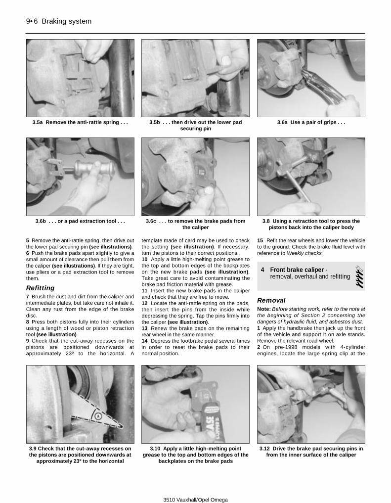
5 Remove the anti-rattle spring, then drive outthe lower pad securing pin (see illustrations).6 Push the brake pads apart slightly to give asmall amount of clearance then pull them fromthe caliper (see illustrations). If they are tight,use pliers or a pad extraction tool to removethem.
Refitting7 Brush the dust and dirt from the caliper andintermediate plates, but take care not inhale it.Clean any rust from the edge of the brakedisc.8 Press both pistons fully into their cylindersusing a length of wood or piston retractiontool (see illustration).9 Check that the cut-away recesses on thepistons are positioned downwards atapproximately 23º to the horizontal. A
template made of card may be used to checkthe setting (see illustration). If necessary,turn the pistons to their correct positions.10 Apply a little high-melting point grease tothe top and bottom edges of the backplateson the new brake pads (see illustration).Take great care to avoid contaminating thebrake pad friction material with grease.11 Insert the new brake pads in the caliperand check that they are free to move.12 Locate the anti-rattle spring on the pads,then insert the pins from the inside whiledepressing the spring. Tap the pins firmly intothe caliper (see illustration).13 Renew the brake pads on the remainingrear wheel in the same manner.14 Depress the footbrake pedal several timesin order to reset the brake pads to theirnormal position.
15 Refit the rear wheels and lower the vehicleto the ground. Check the brake fluid level withreference to Weekly checks.
4 Front brake caliper -removal, overhaul and refitting 4
RemovalNote: Before starting work, refer to the note atthe beginning of Section 2 concerning thedangers of hydraulic fluid, and asbestos dust.1 Apply the handbrake then jack up the frontof the vehicle and support it on axle stands.Remove the relevant road wheel.2 On pre-1998 models with 4-cylinderengines, locate the large spring clip at the
9•6 Braking system
3.5a Remove the anti-rattle spring . . . 3.5b . . . then drive out the lower padsecuring pin
3.6a Use a pair of grips . . .
3.9 Check that the cut-away recesses onthe pistons are positioned downwards at
approximately 23º to the horizontal
3.10 Apply a little high-melting pointgrease to the top and bottom edges of the
backplates on the brake pads
3.12 Drive the brake pad securing pins infrom the inner surface of the caliper
3.6b . . . or a pad extraction tool . . . 3.6c . . . to remove the brake pads fromthe caliper
3.8 Using a retraction tool to press thepistons back into the caliper body
3510 Vauxhall/Opel Omega

side of the brake caliper. The clip is underrelatively high tension and may fly off withsome force when released; to prevent injury,cover the spring with a large rag beforeprising it from the caliper with a stoutscrewdriver.3 Remove the dust caps from the caliperguide pin bolt holes, then slacken both guidepin bolts, and withdraw them from the caliper(see illustrations).4 Withdraw the caliper from its mountingbracket, then tie the caliper to the suspensionstrut, using a suitable piece of wire.
Warning: Take great care to avoidkinking or placing any strain onthe flexible brake hose.
5 On post-1998 models with 4-cylinderengines and all models with 6-cylinder engines,remove both brake pads from the calipermounting bracket.6 On pre-1998 models with 4-cyliner engines,remove the outer pad from the calipermounting bracket, then carefully prise theinner pad from the caliper piston, which isretained by metal spring attached to the rearof the pad backing plate.7 Fit a brake hose clamp to the flexible hoseleading to the brake caliper. Alternativelyremove the cap from the hydraulic fluidreservoir and refit it with a piece of polythenesheeting covering the opening to helpminimise the loss of brake fluid when thecaliper hose is disconnected.8 Clean the area around the union, then undo
the brake hose union bolt, and disconnect thehose from the caliper - be prepared for somebrake fluid leakage. Plug the end of the hoseand the caliper orifice, to prevent dirt enteringthe hydraulic system. Discard the sealingwashers; they must be renewed wheneverdisturbed.9 Slacken and remove the two securing bolts,then detach the caliper mounting bracketfrom the hub carrier (see illustrations).
Overhaul10 With the caliper on the bench, wipe awayall traces of dust and dirt using copiousquantities of brake cleaning fluid.
Warning: Avoid inhaling the brakedust, as it may contain asbestoswhich is injurious to health.
11 On post-1998 models with 4-cylinderengines and all models with 6-cylinder engines,prise open the three tangs and remove theprotective plate from the contact face of thepiston.12 Withdraw the piston from the caliperbody, and remove the dust seal. The pistoncan be withdrawn by hand, or can ifnecessary be pushed out by applyingcompressed air to the brake pipe union bolthole. Only low pressure should be required,such as that generated by a foot pump - placea block of hardwood between the end of thepiston and the caliper body to preventdamage to the piston as it exits from thecylinder.
Warning: Use eye protectionduring this procedure, as dropletsof brake fluid may be ejected as
the piston leaves the cylinder underpressure. Keep your hands away from theend of the piston as it will leave thecylinder with considerable force.13 Using a blunt, non-metallic instrument(such as an old plastic knife), extract thepiston hydraulic seal, taking great care not todamage the caliper bore.14 Press the rubber guide sleeves out of thecaliper body using a suitable socket (seeillustration).15 Thoroughly clean all components, usingonly clean brake fluid as a cleaning medium.Never use mineral-based solvents such aspetrol or paraffin, as they will attack thehydraulic system’s rubber components. Dry thecomponents immediately, using compressedair or a clean, lint-free cloth. Use compressedair to blow clear the fluid passages.
Warning: Wear eye protectionwhen using compressed air!
16 Check all components, and renew any thatare worn or damaged. Pay particular attentionto the cylinder bore and piston; these must berenewed if they are scratched, worn orcorroded in any way (see illustration).
Braking system 9•7
9
4.3a Slacken the upper guide pin bolt,counterholding the guide pin with a
second spanner . . .
4.3b . . . withdraw the guide pin bolt fromthe caliper . . .
4.3c . . . and remove the caliper from itsmounting bracket
4.9a Slacken and remove the two securingbolts . . .
4.9b . . . then detach the caliper mountingbracket from the hub carrier
4.14 Prise open the three tangs andremove the protective plate from the
contact face of the piston
3510 Vauxhall/Opel Omega

Warning: Do not use abrasives ortools to remove any material fromthe piston or cylinder in an attempt
to effect a repair or remove corrosion - thepiston and caliper body must be renewed asa complete assembly. 17 Where applicable, check the condition ofthe guide bolts/pins and their sleeves; bothguide bolts/pins should be undamaged and(when cleaned) a reasonably-tight sliding fit inthe sleeves. If there is any doubt about thecondition of any component, renew it.18 If the assembly is fit for further use, obtainnew piston and dust seals, and a tube ofbrake cylinder paste from a Vauxhall dealer.19 Smear a little brake cylinder paste ontothe surfaces of the caliper bore, piston andpiston seal.20 Install the piston seal in the caliper bore,using only your fingers to manipulate it into itsgroove - do not use tools that may damagethe new seal.21 Fit the new dust seal to the calipercylinder, ensuring that the inner edge seatscorrectly in the cylinder groove.22 Offer up the piston to the cylinder andease the lip at the outer edge of the dust sealover the end of the piston.23 Carefully press the piston to the caliperbore, using a twisting motion, ensuring that itenters the bore squarely.24 Press the piston fully into the bore, until
the outer edge of the dust seal drops into thegroove at the outer edge of the piston. Onpre-1998 models with 4-cyliner engines,rotate the piston so that the raised section ofthe piston contact surface is positionedhorizontally in relation to the caliper body (seeillustration).25 On post-1998 models with 4-cylinderengines and all models with 6-cylinderengines, fit the protective plate in position onthe piston contact surface and press the threetangs into their corresponding recesses.26 Lubricate the rubber caliper guide sleeveswith a little soapy water, then press them intoposition in the caliper body.27 Finally, clean the caliper mounting bracketto remove all traces of dust and corrosion,using a wire brush if necessary. Pay particularattention to the machined surfaces whichcome into contact with the brake pads.
Refitting28 Refit the caliper mounting bracket to thehub carrier, then fit new securing bolts andtighten them to the specified torque.29 Apply a little high-melting-point brakegrease to the areas on the pad backing platesand caliper mounting bracket which contactthe caliper and piston.Caution: Take great care to avoidcontaminating the pad friction materialand brake disc surface.
4-cylinder engined models up to 199830 Fit the inner brake pad to the caliper bypressing the spring clip on the pad backingplate into the piston. Check that the butterflyspring at the edge of the pad bears on theinside of the caliper and is not jammed in thecaliper inspection aperture.31 Place the outer pad in the calipermounting bracket, with the friction materialfacing the disc, and check that it slides freelyalong its guides towards the brake disc.32 Fit the brake caliper and outer pad overthe disc, ensuring that the outer edge of thecaliper bears squarely on the rear of the outerbrake pad’s backing plate. Check that thebutterfly spring at the edge of the pad bearson the inside of the caliper and is not jammedin the caliper inspection aperture.33 Thoroughly clean the threads of thecaliper guide pin bolts, fit them to the caliperand then tighten them to the specified torque.Refit the dust covers.34 Refit the caliper spring, ensuring that itsends are firmly pressed into the holes in theside of the caliper body.
4-cylinder engined models from 1998and all 6-cylinder engined models35 Fit the inner and outer brake pads to thecaliper mounting bracket ensuring that thefriction material is facing the surface of thebrake disc. Check that the pads slide easilyalong their guides towards the brake disc.36 Place the caliper body in position over thebrake pads, ensuring that caliper piston bearsagainst the rear of the inner pad’s backing
plate and that the outer edge of the caliperbears against the rear of the outer pad’sbacking plate. Check that the butterfly springsat the edge of the pad bear on the inside ofthe caliper and are not jammed in the caliperinspection aperture.37 Thoroughly clean the threads of thecaliper guide pin bolts, fit them to the caliperand then tighten them to the specified torque.Refit the dust covers.
All models38 Position a new sealing washer on eachside of the brake hose union, then pass thebolt through the union and thread it into thecaliper. Ensure that the brake hose union iscorrectly positioned against the lug on thecaliper, and tighten the union bolt to thespecified torque setting. Remove the brakehose clamp (where applicable).39 Clip the pad wear sensor into position onthe inner brake pad. If a new sensor is beinginstalled, trace the wiring of the originalsensor back to the connector, thendisconnect it and remove the old sensor fromthe vehicle. Connect the wiring plug of thenew sensor, ensuring that the wiring iscorrectly routed and retained by all thenecessary clips.40 Bleed the hydraulic system as describedin Section 12. Note that, providing the precau-tions described were taken to minimise brakefluid loss, it should only be necessary to bleedthe relevant caliper.41 Refit the roadwheel, then lower the car tothe ground and tighten the roadwheel bolts tothe specified torque.42 Thoroughly check the operation of thebraking system before bringing the vehicleback into service on the public highway.
5 Rear brake caliper -removal, overhaul and refitting 4
Removal1 Chock the front wheels then jack up therear of the vehicle and support it on axlestands. Remove the wheel.2 Fit a brake hose clamp to the flexible hoseleading to the brake caliper (see illustration).
9•8 Braking system
4.16 Extract the piston hydraulic sealusing a blunt, non-metallic instrument
4.24 Rotate the piston so that the raisedsection of the piston contact surface ispositioned horizontally in relation to the
caliper body5.2 Fit a brake hose clamp to the flexible
hose leading to the brake caliper
3510 Vauxhall/Opel Omega

Alternatively remove the cap from thehydraulic fluid reservoir and refit it with a pieceof polythene sheeting covering the opening tohelp prevent loss of brake fluid when thecaliper hose is disconnected.3 Remove the brake pads as described inSection 3.4 Unscrew the union nut securing the rigidbrake line to the caliper, and remove thebrake line (see illustrations).5 Unscrew the hexagon mounting bolts andwithdraw the caliper from the semi-trailingarm (see illustration).
Overhaul6 Clean the outer surfaces of the caliper.7 Note that no attempt must be made toseparate the two halves of the caliper.8 Prise the rings and dust covers from eachside of the caliper and pull the covers from thepiston grooves (see illustration).9 Position a thin piece of wood between thepistons, then using air pressure from an airline or foot pump through the fluid inlet,carefully force the pistons from the cylinders.If one piston exits before the other, removethe piston and then seal off the open cylinderto allow the remaining piston to be ejected.10 Prise the piston seals from the cylinders,taking care not to scratch the bore surfaces.11 Clean the pistons and cylinders with newbrake fluid and allow to dry. Examine thesurfaces of the pistons and cylinder bores forwear, damage and corrosion. If evident, renewthe caliper complete, however if the surfacesare good obtain a repair kit which includespiston seals and dust covers. Also obtain atube of brake cylinder paste.12 Apply a little brake cylinder paste to thepistons, cylinder bores and piston seals.13 Locate the piston seals in the cylindergrooves, then insert the pistons carefully untilthey enter the seals. It may be necessary torotate the pistons to prevent them jamming inthe seals. Do not press the pistons fully intothe cylinders at this stage as it will be difficultto fit the dust covers.14 Ease the dust covers into the pistongrooves then locate them on the caliperhousing. Press the retaining rings over thedust covers.15 Press the pistons into their cylinders, then
rotate them so that the cut-away recesses arepositioned downwards at an angle of ap-proximately 23º; this ensures that only theraised section of the piston contact face bearson the rear of the pad.
Refitting 16 To refit the caliper locate it on thesemi-trailing arm, insert the mounting boltsand tighten them to the specified torque (seeillustration).17 Locate the rigid brake line on the caliperand tighten the union nut to the specifiedtorque.18 Refit the brake pads with reference toSection 3.19 Remove the brake hose clamp orpolythene sheeting and bleed the hydraulicsystem as described in Section 12. Providedthat there has been no loss of brake fluid, itshould only be necessary to bleed the caliperwhich was removed, however if brake fluidhas been lost, then bleed the completesystem.20 Refit the wheel and lower the vehicle tothe ground. Check the operation of thebraking system before using the vehicle.
6 Brake disc -inspection, removal and refitting
3Inspection1 Jack up the front or rear of the vehicle asapplicable and support it on axle stands.Release the handbrake and chock the frontwheels if checking a rear disc. Remove theappropriate wheel.2 Check that the brake disc securing screw istight, then refit and tighten a wheel boltopposite the screw using a spacer washer ap-proximately 10.0 mm (0.4 in) thick.3 Rotate the brake disc and examine it fordeep scoring or grooving. Light scoring isnormal, but if excessive, the disc should beremoved and either renewed or machinedwithin limits by a suitable engineering works.
Braking system 9•9
9
5.4a Unscrew the union nut . . . 5.4b . . . and disconnect the rigid brakeline from the caliper
5.5a Unscrew the hexagon mounting bolts . . .
5.5b . . . and withdraw the caliper from thesemi-trailing arm
5.8 Removing the dust cover ring from therear brake caliper
5.16 Tighten the caliper mounting bolts tothe specified torque
3510 Vauxhall/Opel Omega
Make up a card template tocheck the setting.

It is worth mentioning that some garages maybe able to regrind the discs in situ, using aspecially adapted electric grinder.4 Using a dial gauge, or metal block andfeeler gauges, check that the disc run-outdoes not exceed the amount given inSpecifications, measured at a radius ofapproximately 10.0 mm from the outer edgeof the disc (see illustration). Check therun-out at several positions around the disc.5 If the run-out is excessive, remove the discand check that the disc-to-hub surfaces areperfectly clean. Refit the disc and check therun-out again.6 Check the thickness of the disc using amicrometer at several points across the areaswept by the brake pads (see illustration).Compare your measurement with the figureslisted in the Specifications. If either of thediscs has worn beyond its minimumpermissible thickness at any point, both discsmust be renewed as pair.
Removal7 To remove the brake disc, first remove thebrake pads as described in Section 2 (frontbrake pads) or Section 3 (rear brake pads). Onmodels with 6-cylinder engines and post-1998 models with 4-cylinder engines, unboltthe caliper body from its mounting bracket, asdescribed in Section 4.8 To remove a front disc, remove thesecuring screw then withdraw the disc fromthe hub, tilting it as necessary to clear thebrake caliper (see illustrations). On latermodels it may be necessary to unbolt the
caliper mounting bracket from the hub carrier,as described in Section 4.9 To remove a rear disc, unbolt the brakecaliper from the semi-trailing arm asdescribed in Section 5, and support it awayfrom the disc, taking care not to damage therigid brake line. Slacken the handbrakeadjustment screw via the access hole in brakedisc, as described in Chapter 1, Section 9 -this will retract the handbrake shoes from theinside of the disc. Remove the securing screwand withdraw the brake disc from the hub(see illustrations).
Refitting10 Refitting is a reversal of removal, but makesure that the mating faces of the disc and hubare perfectly clean, and before inserting thesecuring screw apply a little locking fluid to itsthreads. Refit the brake pads with reference to
Section 2 or 3 (as applicable). After refitting arear brake disc, adjust the handbrake asdescribed in Chapter 1, Section 9.
7 Handbrake shoes -inspection, removal and refitting 4
Note: Before starting work, refer to the note atthe beginning of Section 2 concerning thedangers of hydraulic fluid, and asbestos dust.
Inspection1 Remove the rear brake discs as describedin Section 6.2 Brush the dust and dirt from the shoes,backplate and from inside the disc drum.3 Check the thickness of the linings on theshoes and if less than shown in theSpecifications, renew the shoes at both rearbrakes as a complete axle set.4 Also check the surface inside the drums.These should not normally be worn unless thehandbrake has been binding; check thediameter of the inner surface and compare itwith the figure listed in Specifications.
Removal5 Unhook the return spring from the lever onthe rear of the brake backplate then unhookthe handbrake cable from it.6 Using a screwdriver through a hole in thehub flange, twist and remove the brake shoeanti-rattle springs and retaining pins (seeillustration).
9•10 Braking system
6.4 Checking the front brake disc runout 6.6 Checking the thickness of the frontbrake disc using a micrometer
6.8a Remove the securing screw . . .
7.6 Handbrake shoe anti-rattle spring(arrowed) - early model
6.8b . . . then withdraw the front brakedisc from the hub
6.9a Remove the securing screw . . . 6.9b . . . and withdraw the rear brake discfrom the hub
3510 Vauxhall/Opel Omega
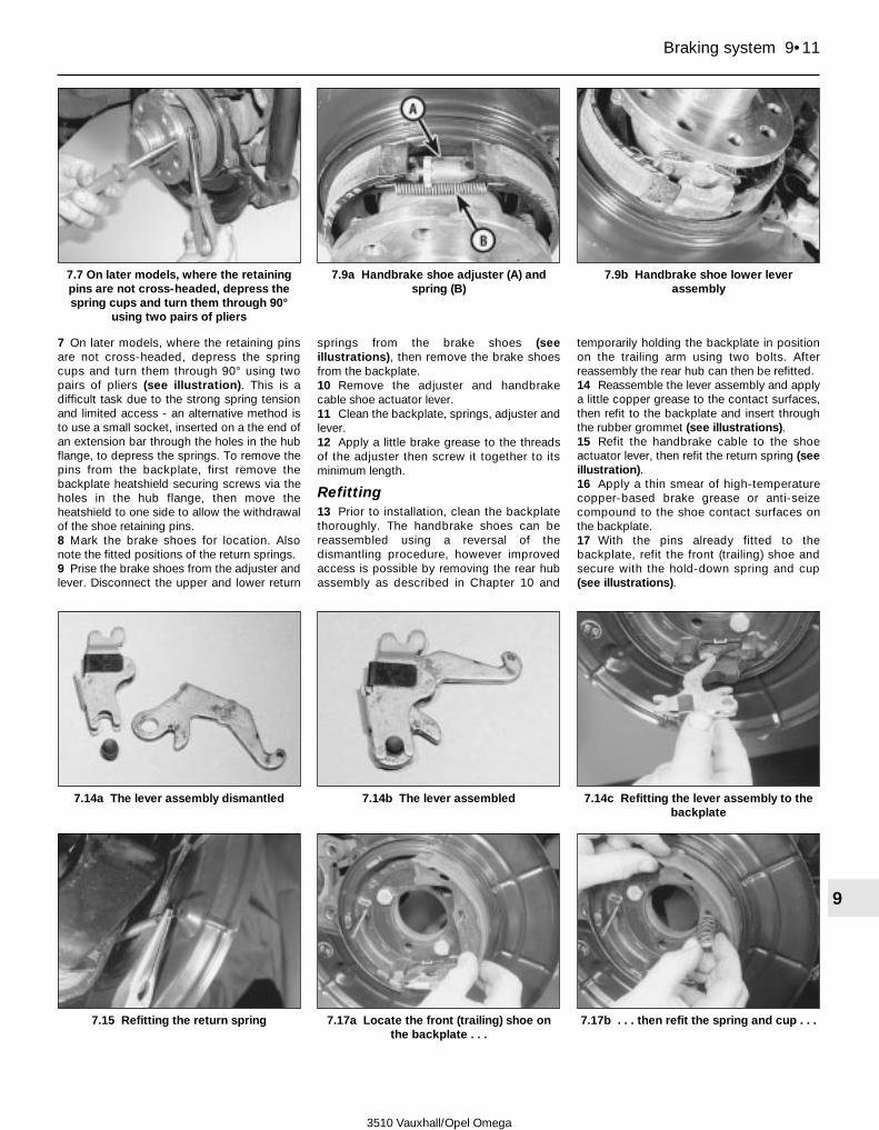
7 On later models, where the retaining pinsare not cross-headed, depress the springcups and turn them through 90° using twopairs of pliers (see illustration). This is adifficult task due to the strong spring tensionand limited access - an alternative method isto use a small socket, inserted on a the end ofan extension bar through the holes in the hubflange, to depress the springs. To remove thepins from the backplate, first remove thebackplate heatshield securing screws via theholes in the hub flange, then move theheatshield to one side to allow the withdrawalof the shoe retaining pins.8 Mark the brake shoes for location. Alsonote the fitted positions of the return springs.9 Prise the brake shoes from the adjuster andlever. Disconnect the upper and lower return
springs from the brake shoes (seeillustrations), then remove the brake shoesfrom the backplate.10 Remove the adjuster and handbrakecable shoe actuator lever.11 Clean the backplate, springs, adjuster andlever.12 Apply a little brake grease to the threadsof the adjuster then screw it together to itsminimum length.
Refitting13 Prior to installation, clean the backplatethoroughly. The handbrake shoes can bereassembled using a reversal of thedismantling procedure, however improvedaccess is possible by removing the rear hubassembly as described in Chapter 10 and
temporarily holding the backplate in positionon the trailing arm using two bolts. Afterreassembly the rear hub can then be refitted.14 Reassemble the lever assembly and applya little copper grease to the contact surfaces,then refit to the backplate and insert throughthe rubber grommet (see illustrations).15 Refit the handbrake cable to the shoeactuator lever, then refit the return spring (seeillustration).16 Apply a thin smear of high-temperaturecopper-based brake grease or anti-seizecompound to the shoe contact surfaces onthe backplate.17 With the pins already fitted to thebackplate, refit the front (trailing) shoe andsecure with the hold-down spring and cup(see illustrations).
Braking system 9•11
9
7.7 On later models, where the retainingpins are not cross-headed, depress thespring cups and turn them through 90°
using two pairs of pliers
7.9a Handbrake shoe adjuster (A) andspring (B)
7.9b Handbrake shoe lower leverassembly
7.15 Refitting the return spring 7.17a Locate the front (trailing) shoe onthe backplate . . .
7.17b . . . then refit the spring and cup . . .
7.14a The lever assembly dismantled 7.14b The lever assembled 7.14c Refitting the lever assembly to thebackplate
3510 Vauxhall/Opel Omega

18 Locate the rear (leading) shoe on the leverassembly and refit the lower return spring(see illustrations).19 Refit the hold-down spring and cup tosecure the leading shoe to the backplate (seeillustration).20 Refit the adjuster between the upper endsof the shoes (see illustration).21 Hook the upper return spring on the shoes(see illustration).22 Where removed the rear hub can now berefitted (see illustration).23 Temporarily refit the disc over the shoesto determine the adjustment, then ifnecessary use a screwdriver to turn theserrated adjuster nut until it is just possible torefit the disc over the shoes without thembinding (see illustration).24 Refit the brake disc with reference toSection 6.
25 Adjust the handbrake as described inChapter 1.26 Refit the roadwheels and lower the vehicleto the ground.
8 Handbrake cable -removal and refitting 3
Removal1 Chock the front wheel, then jack up the rearof the vehicle and support it on axle stands.Remove the rear wheels and release thehandbrake.2 On models with 4-cylinder engines, unhookthe rear and intermediate silencer rubbermountings from their floorpan mountings.Suspend the rear section of the exhaust
system on axle stands, or using lengths ofwire, so that access to the heat shields can begained. See Chapter 4A for details.3 On models with 6-cylinder engines, unboltthe rear section of the exhaust system at thejoints downstream of both catalytic converters.Remove the tailpipe and intermediate silencersfrom underneath the vehicle as a completeassembly. See Chapter 4A for details.4 Unscrew the securing bolts and lower theexhaust system heatshields away from theunderside of the vehicle (see illustration).5 Unscrew and remove the propeller shaftcentre bearing retaining bolts, with referenceto Chapter 8, Section 11. Support the centrebearing on an axle stand.6 Locate the compensator bar at the frontend of the handbrake cable (see illustration).Unscrew the adjustment nut from thethreaded handbrake lever rod, counting the
9•12 Braking system
7.17c . . . and use a pair of pliers todepress and turn the cup
7.18a Refit the rear (leading) shoe and thelower return spring
7.18b Engage the bottom of the shoe onthe lever . . .
7.22 The handbrake shoes assembledready for refitting of the rear hub
7.23 Using a screwdriver through the holein the drive flange to turn the serrated nut
on the adjuster
8.4 Unscrew the securing bolts and lowerthe exhaust system heatshields away from
the underside of the vehicle
7.19 . . . then refit the hold-down springand cup
7.20 Refit the adjuster between the upperends of the shoes
7.21 Hook the upper return spring on theshoes
3510 Vauxhall/Opel Omega

number of turns required to remove it; recordthe number for use later.7 Slide the compensator bar from thethreaded handbrake lever rod.8 Working at each rear brake caliper in turn,unhook the return spring from the lever on therear of the brake backplate, then unhook thehandbrake cable.9 Pull the rear of the outer cable from theguide on the semi-trailing arm on both sides.10 Pull the front ends of the outer cablesfrom the guides, and unhook the inner cables.Release the remainder of each cable from itsrespective retaining clips, then withdraw thecable assembly from under the vehicle.
Refitting11 Refitting is a reversal of removal, notingthe following points:.a) Use a new compensator bar adjustment
nut and screw it onto the threadedhandbrake lever rod by the number ofturns noted during removal.
b) Apply some molybdenum disulphidepaste to the plastic guides at the front ofthe inner cables.
c) Refit the exhaust system with reference toChapter 4A.
d) Refit the propeller shaft centre bearingwith reference to Chapter 8.
e) Finally, adjust the handbrake as describedin Chapter 1.
9 Handbrake lever -removal and refitting 3
Removal1 Chock the front wheels then jack up therear of the vehicle and support it on axlestands.2 Remove the screws and lower the metalheat shield away from the propeller shaftcentre bearing. Unbolt and withdraw thepropeller shaft centre bearing bolts asdescribed in Chapter 8. Support the centrebearing on an axle stand.3 At the front of the handbrake cable unscrewthe adjustment nut from the threadedhandbrake lever rod, and slide off thecompensator bar; see Section 8 for details.4 Prise the rubber gaiter from the underbodyand remove it from the handbrake lever rod.5 Remove the rear section of the centreconsole; see Chapter 11 Section 30 fordetails.6 Unclip and remove the handbrake leverfolding cover. Remove the securing nuts anddetach the air ducting from its supportbracket. Move the ducting to the left, awayfrom the work area.7 Unscrew the handbrake lever mountingsbolts, then disconnect the wiring from thewarning switch.8 Remove the handbrake lever from thevehicle.
Refitting9 Refitting is a reversal of removal, but oncompletion adjust the handbrake cable asdescribed in Chapter 1.
10 Master cylinder -removal and refitting 4
Removal1 Depress the footbrake pedal several timesto dissipate the vacuum in the servo unit.2 Remove the fluid reservoir from the mastercylinder, as described in Section 11.3 Locate a container beneath the mastercylinder to catch spilled brake fluid.4 Identify the brake lines for position, thenunscrew the union nuts and pull the lines fromthe master cylinder. Plug the open ports andbrake pipes to minimise fluid leakage andprevent the ingress of foreign material.5 Unscrew the mounting nuts and withdrawthe master cylinder from the studs on thevacuum servo unit (see illustration). Takecare not to drop any brake fluid on the bodypaintwork. If accidentally spilt, wash offimmediately with copious amounts of coldwater.6 Extract the O-ring seal from the mastercylinder sealing surface, and the rubbergrommets from the fluid reservoir ports, thendiscard them as new items must be fitted.
Refitting7 Fit a new O-ring seal to the master cylindermating surface, and new rubber grommets tothe fluid reservoir ports.8 Refit the master cylinder to the brake servo,then fit and tighten the mounting nuts to thespecified torque.9 Reconnect the brake pipes to the mastercylinder ports and tighten the unions to thespecified torque. A crow’s-foot adapter maybe required to apply torque to the union nuts.10 Refit the brake fluid reservoir as describedin Section 11.11 On completion, bleed the entire brakehydraulic system as described in Section 12.12 Check the master cylinder unions forsigns of leakage and test the operation of thebraking system thoroughly before using thevehicle on the road.
11 Brake fluid reservoir and level sensor -removal and refitting
2Reservoir
Removal1 Ensure that ignition key is turn to the Offposition, then unplug the wiring from the fluidreservoir level sensor at the connector.2 Unscrew the cap from the fluid reservoir,then remove as much of the brake fluid as ispossible; use an old poultry baster or similartool - do not siphon the fluid out as it ispoisonous. Discard the fluid as it will not be fitfor re-use.3 Slacken and separate the union, thendisconnect the clutch master cylinder supplypipe from the side of the fluid reservoir.4 Carefully prise the fluid reservoir from thebrake master cylinder ports. Extract therubber grommets from the brake mastercylinder and discard them. Clean the ports atthe base of the fluid reservoir.
Refitting5 Fit new rubber grommets to the brakemaster cylinder ports.6 Press the fluid reservoir into the brakemaster cylinder ensuring that the rubbergrommets do not become dislodged.7 Reconnect the clutch master cylindersupply pipe, then tighten the union securely.8 Fill the reservoir up the MAX marking withnew brake fluid of the specified grade.9 On completion, bleed the brake hydraulicsystem as described in Section 12. Check theoperation of the braking system before usingthe vehicle on the road.
Level sensor
Removal10 The sensor is integral with the brake fluidreservoir filler cap. Ensure that ignition key isturn to the Off position, then unplug the wiringfrom the sensor at the connector.
Braking system 9•13
9
8.6 Handbrake cable compensator baradjuster nut (arrowed)
10.5 Master cylinder mounting nuts(arrowed)
3510 Vauxhall/Opel Omega

11 Unscrew the cap from the reservoir andallow the excess fluid to drain off.
Refitting12 Refitting is a reversal of removal. Afterreconnecting the wiring, the operation of thesensor can be tested by suspending thereservoir cap above the reservoir, so that thefloat slides down to the end of its travel. Thefacia tell-tale warning lamp should illuminate.
12 Hydraulic system -bleeding 3
Warning: Hydraulic fluid ispoisonous; thoroughly wash offspills from bare skin without
delay. Seek immediate medical advice ifany fluid is swallowed or gets into the eyes.Certain types of hydraulic fluid areflammable and may ignite when broughtinto contact with hot components; whenservicing any hydraulic system, it is safestto assume that the fluid is inflammable andto take precautions against the risk of fireas though it were petrol that was beinghandled. Hydraulic fluid is an effectivepaint stripper and will also attack manyplastics. If spillage occurs onto paintedbodywork or fittings, it should be washedoff immediately, using copious quantitiesof fresh water. It is also hygroscopic i.e. itcan absorb moisture from the air, whichthen renders it useless. Old fluid may havesuffered contamination and should neverbe re-used. When topping-up or renewingthe fluid, always use the recommendedgrade, and ensure that it comes from anew, sealed container.
General information1 The correct operation of any hydraulicbraking system relies on the fact that the fluidused in it is incompressible, otherwise theeffort exerted at the brake pedal and mastercylinder will not be fully transmitted to thebrake calipers or wheel cylinders. Thepresence of contaminants (such as air) in thehydraulic system will result in a spongy feel tothe brakes and unpredictable performance, in
the form of brake fade or at worst brakefailure. In addition, brake fluid deteriorateswith age through oxidation and waterabsorption. This lowers its boiling point andmay cause vaporisation under hard braking,again affecting brake performance. For thisreason, old or contaminated brake fluid mustbe renewed regularly (see Chapter 1 for theservice interval) - this is achieved by bleedingthe entire system. Similarly, if you havedisturbed any part of the hydraulic systemduring repair or servicing, the system must bebled to remove the air that will have beenadmitted.2 When refilling the system, use only clean,new hydraulic fluid of the recommended typeand grade; never re-use fluid that has alreadybeen bled from the system. Ensure thatsufficient fluid is available before starting work.3 If there is any possibility of there beingincorrect fluid in the system already, the brakecomponents and circuits must be flushedcompletely with new fluid of the correct typeand grade and new seals should be fittedthroughout the system.4 If hydraulic fluid has been lost from thesystem, or air has entered because of a leak,ensure that the fault is corrected beforeproceeding further.5 Park the vehicle on level ground, switch offthe engine and select first or reverse gear(manual transmission) or Park (automatictransmission), then chock the wheels andrelease the handbrake.6 Check that all pipes and hoses are secure,unions tight and bleed screws closed.Remove the dust caps and clean off all dirtfrom around the bleed screws.7 Unscrew the master cylinder reservoir cap,and top the master cylinder reservoir up to theMAX level line; refit the cap loosely, andremember to maintain the fluid level at leastabove the MIN level line throughout theprocedure, otherwise there is a risk of furtherair entering the system, as the level drops.8 There are a number of one-man, do-it-yourself brake bleeding kits currently availablefrom motor accessory shops. It isrecommended that one of these kits is usedwhenever possible, as they greatly simplifythe bleeding operation, and also reduce therisk of expelled air and fluid being drawn back
into the system. If such a kit is not available,the basic (two-man) method must be used,which is described in detail below.9 If a kit is to be used, prepare the vehicle asdescribed previously, and follow the kitmanufacturer’s instructions, as the proceduremay vary slightly according to the type beingused. Generally, they are as outlined below inthe relevant sub-section.10 Whichever method is used, the samesequence must be followed to ensure theremoval of all air from the system.
Bleeding sequenceNote: It is possible to partially bleed thesystem, i.e. just one brake line and caliper at atime. Providing fluid loss is kept to a minimumand air is not drawn into the system, it will notbe necessary to bleed the other brake lines aswell.
Pre-1998 models with 3-channel ABS11 Bleed the system in the followingsequence:.
1 Front left hand brake2 Front right hand brake3 Rear left hand brake4 Rear right hand brake
Post-1998 models with 4-channel ABS12 Bleed the system in the followingsequence:.
1 Left-hand rear brake.2 Right-hand front brake.3 Right-hand rear brake.4 Left-hand front brake.
Bleeding - basic (two-man) method13 Obtain a clean glass jar, a suitable lengthof plastic or rubber tubing which is a tight fitover the bleed screw, and a ring spanner to fitthe screw. Alternatively, a proprietary brakebleeding kit can be obtained. Note: The helpof an assistant will also be required.14 Remove the dust cap from the firstcaliper’s bleed screw. Fit the spanner over thebleed screw and push the tube onto the bleedscrew nipple (see illustrations). Place theother end of the tube in the jar and pour insufficient fluid to cover the end of the tube.15 Throughout the procedure, keep an eyeon the reservoir fluid level and ensure that it ismaintained above the MIN level line as thebrakes are bled; top it up before starting ifnecessary.16 Have the assistant fully depress the brakepedal several times to build up pressure - thenon the final downstroke, keep it depressed.17 While pedal pressure is maintained,slacken the bleed screw (approximately oneturn) and allow the brake fluid to flow into thejar. Pedal pressure should be maintainedthroughout; follow the pedal down to the endof its travel if necessary, but do not release it.When the flow stops, tighten the bleed screwagain, then have your assistant release thepedal slowly. Re-check the reservoir fluid leveland top it up if necessary.
9•14 Braking system
12.14a Remove the dust cap from thecaliper bleed screw
12.14b Fit the spanner over the bleedscrew and push the tube onto the bleed
screw nipple
3510 Vauxhall/Opel Omega

18 If air is present in the brake lines, it willappear as bubbles in the expelled fluid.Repeat the steps given in the two previousparagraphs until the fluid emerging from thebleed screw is free from air bubbles. If themaster cylinder has been drained and refilledand air is being bled from the first brake line inthe sequence, allow several seconds betweencycles for the master cylinder passages torefill.19 When no more air bubbles appear, tightenthe bleed screw securely, remove the tubeand spanner then refit the dust cap.Caution: Do not overtighten the bleedscrew.20 Repeat the procedure on the remainingbrake lines to be bled, until all air is removedfrom the system and the brake pedal feelsfirm again.
Bleeding - using a one-way valve kit21 As their name implies, these kits consistof a length of tubing with a one-way valvefitted, to prevent expelled air and fluid beingdrawn back into the system; some kits includea translucent container, which can bepositioned so that the air bubbles can bemore easily seen flowing from the end of thetube.22 The kit is connected to the bleed screw,which is then opened. The user returns to thedriver’s seat, depresses the brake pedal witha smooth, steady stroke and slowly releasesit; this process is repeated until the expelledfluid is free of air bubbles .23 Note that the use of these kits cansimplify the bleed operation so much, that it iseasy to forget the reservoir fluid level. Ensurethat it is maintained at least above the MINlevel line at all times, or air may be drawn intothe system.
Bleeding - using a pressure-bleeding kit24 These kits are usually powered bypressurised air, such as that provided by thevehicle’s spare tyre. However, note that it willprobably be necessary to reduce the tyrepressure to a lower level than normal beforeconnecting to the bleeding kit; refer to themanufacturer’s instructions supplied with thekit.25 The method involves connecting apressurised, fluid-filled container to themaster cylinder reservoir. Bleeding can thenbe carried out simply by opening each bleedscrew in turn, and allowing the fluid to flowout under moderate pressure until no more airbubbles can be seen in the expelled fluid.26 This method has the advantage that thelarge reservoir of fluid provides an additionalsafeguard against air being drawn into thesystem during bleeding.27 Pressure-bleeding is particularly effectivewhen bleeding difficult systems, or whenbleeding the complete system at the time ofroutine fluid renewal.
All methods28 When bleeding is complete, and firmpedal feel is restored, wash off any spilt fluid,tighten the bleed screws securely, and refittheir dust caps (where applicable).29 Check the hydraulic fluid level in themaster cylinder reservoir; top it up ifnecessary (see Weekly checks).30 Dispose of any hydraulic fluid that hasbeen bled from the system; it must not be re-used.31 Check the feel of the brake pedal. If itfeels at all spongy, or has greater travel thanexpected, it is probable that air is still presentin the system; further bleeding will thereforebe required. If the bleeding procedure hasbeen repeated several times and brake feelhas still not been restored, the problem maybe caused by air trapped in ABS hydraulicmodulator. This can be dislodged byactuating the ABS return pump during thebleeding process, but note that this operationcan only be carried out by a Vauxhall dealerwith the necessary ABS diagnosticequipment.
13 Hydraulic brake lines and hoses -removal and refitting
31 Remove the cap from the brake fluidreservoir and refit it with a piece of polythenesheeting covering the opening to help preventsubsequent loss of brake fluid.2 Jack up the front or rear of the vehicle, asapplicable, and support it on axle stands.
Front flexible hose3 Remove the front wheel.4 Turn the steering on full lock. Unscrew thebolt securing the hose to the caliper andrecover the copper washers.5 Pull the locking plates from the mountingsand disconnect the hose from the retainingclips.6 Unscrew the rigid brake line union, andremove the hose.7 Refitting is a reversal of removal, but makesure that the hose is not twisted or kinked.Bleed the hydraulic system as described inSection 12 .
Rear flexible hose8 Pull the locking plates from the mountings.9 Unscrew the rigid brake line unions, andremove the hose.10 Refitting is a reversal of removal, butmake sure that the hose is not twisted orkinked. Bleed the hydraulic system asdescribed in Section12 .
Brake lines11 Some commonly-used brake lines can beobtained from GM parts stores alreadyformed complete with unions, however otherbrake lines must be prepared from brakepipes of the required diameter. Kits for making
the brake lines can be obtained from motoraccessory shops.12 To remove a brake line, unscrew theunions at each end and release it from theclips.13 Refitting is a reversal of removal. Bleed thehydraulic system as described in Section 12.
14 Vacuum servo hose and non-return valve -renewal
31 When new, the vacuum hose is shrunk ontothe non-return valve using a heat process,therefore when the valve is first renewed it isnecessary to fit a conventional vacuum hose,using hose clips to secure the valve.Thereafter the hose and valve may berenewed separately.2 Unscrew the hose union nut at the inletmanifold.3 Pull or prise the elbow connector out of theservo. Note that some models may beequipped with a quick-release fitting. Todisconnect the fitting, depress the catch atthe side of the fitting and separate the twohalves of the fitting.4 Release the hose from the plastic straps.Where applicable, unplug the narrow-borevacuum hose from the T-piece.5 Cut the hose off the non-return valve, theelbow and the inlet manifold union.6 Cut the new braided vacuum hoses tolength (it is sold in 5.0 metre lengths) andsecure to the non-return valve, elbow andunion using proprietary clips. Make sure thatthe arrows on the valve point towards the inletmanifold end.7 Press the elbow into the servo rubbergrommet (or reconnect the quick-releaseunion, as applicable) and tighten the union nuton the inlet manifold. Fit new plastic straps tosecure the hose in position. Reconnect thenarrow-bore vacuum hoses to the T-pieces.8 Check the operation of the vacuum servo(see Section 15), then entire braking system,before using the vehicle on the road.
15 Vacuum servo unit -testing, removal and refitting 3
Testing1 To establish whether or not the servo isoperating, proceed as follows.2 With the engine stopped, apply the brakepedal several times in order to dissipate thevacuum from the servo unit.3 Hold the brake pedal depressed, then startthe engine. The pedal should move a smalldistance towards the floor with the additionalassistance of the servo unit. If not, check thevacuum hose and non-return valve. If theseprove to be satisfactory, the servo unit itself isfaulty and should be renewed.
Braking system 9•15
9
3510 Vauxhall/Opel Omega

Removal4 Depress the footbrake pedal several timesto dissipate the vacuum in the servo unit.5 Disconnect the wiring for the brake fluidlevel warning lamp from the reservoir fillercap.6 With reference to Chapter 12, remove bothwindscreen wiper arms from their respectiveshafts.7 Carefully peel the rubber sealing strips fromthe rear edge of the engine compartmentbulkhead, then remove the securing screwsand withdraw the cowl panel from the loweredge of the windscreen.8 Unscrew the master cylinder mounting nutsand pull the unit from the studs on thevacuum servo unit sufficiently to allow roomfor removal of the servo unit. Leave the brakelines connected to the master cylinder, but donot exert excessive force on the brake lines asthis may cause them to fracture.9 Pull or prise out the vacuum hose elbowconnector, or unplug the quick-releaseconnector, as applicable. Move the bulkheadwiring harness to one side.10 Working inside the vehicle, in the driver’sfootwell, remove the screws and lower thecover panel away from the underside of thefacia. Unscrew the fixings and remove thefootwell air ducting.11 Unhook the return spring from the brakepedal. Remove the brake light switch from itsmounting bracket (see Chapter 12, Section 4).12 Extract the spring clip and pull out theclevis pin, to disconnect the servo pushrodfrom the brake pedal.
13 Unscrew the mounting nuts, then tilt theservo unit and remove it from the bulkheadinto the engine compartment. Recover thegasket. Note that the nuts double up as thebrake pedal bracket mounting nuts (seeSection 16).14 Loosen the locknut and unscrew theclevis fork from the pushrod. Unscrew thelocknut.15 Unscrew the nuts and remove the supportbracket and gaskets from the servo unit.
Refitting16 Commence refitting by placing thesupport bracket together with a new gasket inposition on the servo and tightening thesecuring nuts to the specified torque.17 Screw the locknut and clevis fork onto thepushrod. With the pushrod in its rest positionadjust the fork so that the distance betweenthe servo support bracket face and the clevispin centre line is 106.0 + 0.5 mm. Tighten thelocknut to secure the fork in this position.18 Refit the servo unit to the bulkhead usinga new gasket. Fit the mounting nuts andtighten them to the specified torque.19 Connect the pushrod to the brake pedalwith the clevis pin and spring clip.20 Reconnect the brake pedal return springs,then refit the brake light switch with referenceto Chapter 12, Section 4.21 Refit the footwell ventilation ducting andfacia lower cover panelling.22 Press the vacuum hose elbow connectorin the servo rubber grommet, or reconnect thequick release fitting, as applicable.
23 If necessary, renew the O-ring seal on themaster cylinder flange then locate the unit onthe servo studs and tighten the mounting nuts(see Section 10 for details).24 Press the brake pipes firmly into theirretaining clips on the engine compartmentbulkhead.25 Reconnect the level sensor wiring to thebrake fluid reservoir filler cap.26 Refit the cowl panel to the lower edge ofthe windscreen, and secure it in position withthe screws.27 Press the rubber sealing strips intoposition at the rear of the enginecompartment, then refit the windscreen wiperarms with reference to Chapter 12.28 Test the operation of the vacuum servo asdescribed at the beginning of this Section.Test the operation of the entire brakingsystem before using the vehicle on the road.
16 Brake pedal -removal and refitting 3
Removal1 Working inside the vehicle, in the driver’sfootwell, remove the screws and lower thecover panel away from the underside of thefacia. Unscrew the fixings and remove thefootwell air ducting.2 Disconnect the wiring from the brakestop-lamp switch, then unclip the switch fromthe pedal bracket, noting its fitted position.3 Unhook both the brake pedal returnsprings.4 Extract the spring clip and pull out theclevis pin securing the servo pushrod to thebrake pedal.5 Slacken and withdraw the uppermost pedalbracket securing bolt.6 Unscrew the nuts holding the pedal bracketto the bulkhead; note that these nuts doubleup as the servo mounting nuts (see Section15). Pull the servo away from the bulkheadslightly, to withdraw the servo studs frompedal bracket.7 Pivot the bracket downwards to release itfrom the upper servo studs then remove thebracket and pedal assembly from the vehicle.8 Remove the spring clip, the unscrew thenut from the end of the pedal shaft, andremove the washer.9 Remove the pedal location clips andcarefully drive the shaft from the bracket, untilthe brake pedal can be removed. Recover thethrust washers (where fitted) and the centrespring (see illustration).
Refitting10 Refitting is a reversal of removal, butlubricate the pedal shaft with grease. Tightenall fixings to the specified torque whereapplicable. Refer to the information given inChapter 12, Section 4 when refitting the brakelight switch.
9•16 Braking system
3510 Vauxhall/Opel Omega
16.9 Brake pedal and associated components
1 Pedal bracket2 Spring clip
3 Nut4 Washer
5 Return spring6 Pedal shaft
7 Pedal

17 Anti-lock Braking System/Traction Control system(ABS/TC) - information
4Information1 ABS is fitted as standard to all models.Traction control is fitted as standard tomodels with 6-cylinder engines.2 The ABS system comprises a hydraulicmodulator and electronic control unit togetherwith four roadwheel sensors. The hydraulicmodulator contains the electronic control unit(ECU), the hydraulic solenoid valves and theelectrically-driven return pump. The purposeof the system is to prevent the road wheel(s)locking during braking. This is achieved byautomatic adjustment of the hydraulicpressure applied to the brake on the wheel(s)that is/are about to skid. During normaloperation, the system functions in the sameway as a non-ABS braking system. In theevent of ABS failure, the braking systemreverts to conventional, non-ABS operation.3 The solenoid valves are controlled by theECU, which receives wheel rotation speedinformation from each of the four wheel speedsensors. By comparing these signals, the ECUcan determine the speed at which the vehicleis travelling. It can then use this speed todetermine when a wheel is decelerating at anabnormal rate, compared to the speed of thevehicle, and therefore predicts when a wheelis about to lock.4 If the ECU senses that a wheel is about tolock, it operates the relevant solenoid valve(s)in the hydraulic unit, which then isolates fromthe master cylinder the relevant brake(s) onthe wheel(s) which is/are about to lock,effectively sealing-in the hydraulic pressure.On models built before 1998 model year, thetwo front brakes are modulated separately,but the two rear brakes are modulatedtogether via a shared hydraulic circuit. Onlater models, the hydraulic pressure to eachcaliper is modulated individually.5 If the speed of rotation of the wheelcontinues to decrease at an abnormal rate,the ECU operates the electrically-driven pumpwhich pumps the hydraulic fluid back into themaster cylinder, releasing the brake. Once thespeed of rotation of the wheel returns to anacceptable rate, the pump stops, and thesolenoid valves switch again, allowing thehydraulic master cylinder pressure to return tothe caliper/wheel cylinder (as applicable),which then re-applies the brake. This cyclecan be carried out many times per second.6 The action of the solenoid valves and returnpump creates pulses in the hydraulic circuit.When the ABS system is functioning, thesepulses can be felt through the brake pedal andthe return pump can also be heard to operate.7 On models with 6-cylinder models, thehydraulic unit incorporates an additional set ofsolenoid valves which operate the TractionControl (TC) system. The system operates at
speeds up to approximately 30 mph (60 km/h)using the signals supplied by the wheel sensors.If the ECU senses that a driving wheel is about tolose traction, it prevents this by momentarilyapplying the relevant rear brake.8 The operation of the ABS and the tractioncontrol system is entirely dependent onelectrical signals. To prevent the systemresponding to any inaccurate signals, a built-in safety circuit monitors all signals receivedby the ECU. If an inaccurate signal or lowbattery voltage is detected, the system isautomatically shut down, and the warninglight on the instrument panel is illuminated, toinform the driver that the system is notoperational. Normal braking is still available,however.
Precautionsa) Do not disconnect the ABS/TC control
unit multiway harness plug with theignition switched on.
b) Do not use a battery booster to start theengine.
c) Unplug the multi-way wiring connectorfrom the ABS/TC control unit beforecarrying out any electrical welding on thecar.
d) Do not expose the unit to temperaturesexceeding 80ºC (e.g. during paint-ovenwork).
18 Anti-lock Braking System/Traction Control system -component removal and refitting
4Hydraulic modulator - early models with (3-channel)ABS 2-SH or 2-SH/TC
Removal1 Disconnect the battery negative cable andposition it away from the terminal.2 Remove the cap from the brake fluidreservoir and refit it with a piece of polythenesheeting covering the opening to help preventsubsequent loss of brake fluid.3 Unplug the wiring from the alarm systembonnet switch, then unscrew the bolt from thepower steering reservoir clamp and tie thereservoir to one side.4 Remove the ABS control unit as describedlater in this Section. Undo the securingscrews and remove the ABS control unitmounting bracket from the modulator.
4-cylinder engined models5 Identify all five brake lines on the modulatorfor location, then unscrew the union nuts andpull the brake lines just clear of the modulator.Be prepared for brake fluid leakage - place asuitable container underneath the unionsbefore disconnection. If possible, plug theends of the brake lines, or at least cover themto prevent excessive fluid brake fluid loss theingress of dust and dirt. Also cover thehydraulic modulator ports.
6 Slacken and remove the securing screws,then remove the heat shield from themodulator.
6-cylinder engined models7 Identify the three uppermost brake lines onthe modulator for location, then unscrew theunion nuts and pull the brake lines just clearof the modulator. Be prepared for brake fluidleakage - place a suitable containerunderneath the unions before disconnection.If possible, plug the ends of the brake lines,or at least cover them to prevent excessivefluid brake fluid loss the ingress of dust anddirt. Also cover the hydraulic modulatorports.8 Apply the handbrake, raise the front of thevehicle and rest it securely on axle stands.9 Remove the engine compartment lowercover panel to allow access to the undersideof the hydraulic modulator.10 Slacken and remove the securing screws,then remove the heat shield from themodulator.11 Identify the two lowermost brake lines onthe modulator for location, then unscrew theunion nuts and pull the brake lines just clear ofthe modulator. Again, be prepared for brakefluid leakage.
All models12 Unscrew the nut and disconnect the earthcable from the rear of the hydraulic modulator.13 Unscrew the securing nuts from thehydraulic modulator guide pins, then movethe brake lines carefully to one side and slidethe modulator from the guide pins.14 Remove the modulator from the enginecompartment taking care to prevent brakefluid from running out of the modulator ports.15 Check that the guide pin rubbermountings on the modulator are in goodcondition. No further dismantling of thehydraulic modulator is possible.
Refitting16 Refitting is a reversal of removal buttighten all nuts and bolts to the correct torque(where specified), and finally bleed thehydraulic system as described in Section 12.Check that the ABS warning light extinguishesat the first application of the brake pedal afterstarting the engine. On completion take thevehicle to a GM dealer and have the system’soperation verified with ABS test equipment.
Hydraulic modulator andABS/TC control unit - later models with (4-channel)ABS 5.3 or 5.3/TC
Removal17 Disconnect the battery negative cable andposition it away from the terminal.18 Apply the handbrake, raise the front of thevehicle and support it securely on axle stands.19 Undo the screws and lower the coverpanel away from the underside of the enginecompartment.
Braking system 9•17
9
3510 Vauxhall/Opel Omega

20 Unscrew the fixings and remove the heatshield from the side of the hydraulicmodulator.21 With reference to Chapter 10 Section 26disconnect the high pressure hydraulic fluiddelivery pipe from the power steering pump.Position a container underneath thedisconnected union to catch escapinghydraulic fluid.22 Unclip the cover from the enginecompartment auxiliary fusebox and detachthe fuseholder from the base of the fusebox.23 Unclip the cover from the enginecompartment relay box. Withdraw the enginemanagement system electronic control unit,then unplug the multiway connector from it;refer to Chapter 4A for details.24 Release the engine management systemrelay from the relay box, together with itsmounting bracket.25 Disconnect the three main wiring harnessplugs located at the rear of the main enginecompartment fusebox.26 Remove as much hydraulic fluid aspossible from the power steering fluidreservoir, using an old (but clean) poultrybaster or similar.27 Slacken the hose clips and disconnect thetwo fluid hoses from the base of the powersteering fluid reservoir. Place a suitablecontainer underneath the reservoir to catchthe hydraulic fluid that will run out.28 Remove the power steering fluid reservoirfrom its mounting bracket then unbolt thebracket from the bodywork and remove it.29 Undo the securing screw and unplug themultiway wiring harness connector from theABS/TC control unit.30 Remove as much hydraulic fluid aspossible from the brake fluid reservoir, usingan old (but clean) poultry baster or similar.31 With reference to Section 10, undo theunions and disconnect the brake pipes fromthe side of the master cylinder. Place asuitable container underneath the reservoir tocatch the brake fluid that will run out. Plug theends of the brake lines.32 Carefully label all six brake lines at thehydraulic modulator (to ensure that they arereconnected in correct order later) thenunscrew the union nuts and pull the brakelines just clear of the modulator. Be prepared
for brake fluid leakage - place a suitablecontainer underneath the unions beforedisconnection. If possible, plug the ends ofthe brake lines, or at least cover them toprevent excessive fluid brake fluid loss, andthe ingress of dust and dirt. Also cover thehydraulic modulator ports.33 Detach the hydraulic modulator from itsmounting bracket and remove it from theengine compartment, taking care to preventbrake fluid from running out of the modulatorports.
Refitting34 Refitting is a reversal of removal, notingthe following points:.a) Tighten all nuts and bolts to the correct
torque (where specified)b) Top up the power steering system with
the correct grade of fluid as described inWeekly checks.
c) Bleed the hydraulic system as describedin Section 12.
d) Check that the ABS warning lightextinguishes at the first application of thebrake pedal after starting the engine.
e) On completion take the vehicle to a GMdealer and have the system’s operationverified with ABS test equipment.
ABS/TC control unit - early models with (3-channel)ABS 2-SH or 2-SH/TC
Removal35 Disconnect the battery negative cable andposition it away from the terminal.36 Unscrew the securing bolt and removethe cover panel from the ABS/TC control unit.37 Unplug the three multiway wiring harnessconnectors from the ABS/TC control unit.38 Slacken and remove the securing boltsand then lift the ABS/TC control unit awayfrom the engine compartment.Refitting.39 Refitting is a reversal of removal. Oncompletion take the vehicle to a GM dealerand have the system’s operation verified withABS test equipment.
Traction Control switch
Removal40 Ensure that ignition key is turned to the
Off position, then carefully prise the switchfrom the facia panel, using a smallscrewdriver. Use card or cloth to preventdamage to the facia.41 Unplug the wiring connector from the rearof the switch.
Refitting42 Refitting is a reversal of removal.
Front wheel speed sensorsRemoval43 Disconnect the battery negative lead.44 Apply the handbrake, then jack up thefront of the vehicle and support it on axlestands (see Jacking and Vehicle Support).Remove the relevant front roadwheel.45 Disconnect the sensor wiring and releaseit from the clips on the front suspension strutand wheel arch. Do not confuse it with thebrake pad wear sensor wiring connector.46 Unscrew the mounting bolt using a Torxkey and withdraw the sensor from themounting bracket (see illustrations).
Refitting47 Refitting is a reversal of removal butsmear a little anti-seize grease on the sides ofthe sensor casing before inserting it. Oncompletion take the vehicle to a GM dealerand have the system’s operation verified withABS test equipment.
ABS rear wheel speed sensorsRemoval48 Disconnect the battery negative lead.49 Chock the front wheels, then jack up therear of the vehicle and support it on axlestands (see Jacking and Vehicle Support).Remove the relevant rear roadwheel.50 Disconnect the sensor wiring and releaseit from the clips on the underbody.51 Unscrew the mounting bolt using a Torxkey and withdraw the sensor from the finaldrive unit (see illustration).
Refitting52 Refitting is a reversal of removal butsmear a little anti-seize grease on the sides ofthe sensor casing before inserting it into thefinal drive unit. On completion take the vehicleto a GM dealer and have the system’soperation verified with ABS test equipment.
9•18 Braking system
18.46a Unscrew the mounting bolt . . . 18.46b . . . and withdraw the ABS sensor 18.51 ABS rear wheel speed sensors(arrowed)
3510 Vauxhall/Opel Omega

3510 Vauxhall/Opel Omega
10•1
10
Chapter 10Suspension and steering
Front suspensionType . . . . . . . . . . . . . . . . . . . . . . . . . . . . . . . . . . . . . . . . . . . . . . . . . . . . Independent MacPherson struts, coil springs and anti-roll bar,
double-acting telescopic shock absorbers. Adjustable camber.
Rear suspensionType . . . . . . . . . . . . . . . . . . . . . . . . . . . . . . . . . . . . . . . . . . . . . . . . . . . . Independent, semi-trailing arms and coil springs, anti-roll bar, double-
acting telescopic shock absorbers. Adjustable track control arms.
SteeringType . . . . . . . . . . . . . . . . . . . . . . . . . . . . . . . . . . . . . . . . . . . . . . . . . . . . Recirculating ball, worm shaft and nut with sector shaft and drop arm,
adjustable track control rods. Hydraulic power-assistance on all models,Servotronic speed-sensitive power assistance on 6-cylinder models.
Overall steering ratio . . . . . . . . . . . . . . . . . . . . . . . . . . . . . . . . . . . . . . . . 14.8:1Lubricant quantity . . . . . . . . . . . . . . . . . . . . . . . . . . . . . . . . . . . . . . . . . . 1.3 litresHydraulic fluid pressure:
At full lock . . . . . . . . . . . . . . . . . . . . . . . . . . . . . . . . . . . . . . . . . . . . . . 100 to 110 barAt rest in centre position . . . . . . . . . . . . . . . . . . . . . . . . . . . . . . . . . . . 2 to bar
Front suspensionCoil springs (typical): Colour code Spring length Compression rate
SOHC 4-cylinder engines up to 1998 . . . . . . . . . . . . . . . . . . . . . . . . . Blue/Brown 368 mm 21 N/mmDOHC 4-cylinder engines, with air conditioning from 1998 . . . . . . . . Blue/Orange 390 mm 21 N/mm6-cylinder engines, without air conditioning, up to 1998 . . . . . . . . . . Yellow/Lilac 362 mm 24 N/mm6-cylinder engines, with air conditioning, from 1998 . . . . . . . . . . . . . Brown/Brown 373 mm 24 N/mm
Front anti-roll bar - removal and refitting . . . . . . . . . . . . . . . . . . . . . . 6Front anti-roll bar drop link - removal and refitting . . . . . . . . . . . . . . 7Front hub and bearings - removal and refitting . . . . . . . . . . . . . . . . . 9Front lower suspension arm - removal and refitting . . . . . . . . . . . . . 4Front suspension subframe - removal and refitting . . . . . . . . . . . . . . 10Front suspension lower balljoint - renewal . . . . . . . . . . . . . . . . . . . . 5Front suspension strut - camber adjustment . . . . . . . . . . . . . . . . . . 3Front suspension strut - removal. overhaul and refitting . . . . . . . . . . 2General description . . . . . . . . . . . . . . . . . . . . . . . . . . . . . . . . . . . . . . 1Power steering pump - removal and refitting . . . . . . . . . . . . . . . . . . 27Rear anti-roll bar - removal and refitting . . . . . . . . . . . . . . . . . . . . . . 14Rear axle (complete assembly) - removal and refitting . . . . . . . . . . . 17Rear coil spring - removal and refitting . . . . . . . . . . . . . . . . . . . . . . . 13Rear hub and bearing - removal and refitting . . . . . . . . . . . . . . . . . . 20Rear semi-trailing arm - removal and refitting . . . . . . . . . . . . . . . . . . 12
Rear shock absorber - removal and refitting . . . . . . . . . . . . . . . . . . . 11Rear suspension level control system - component removal and
refitting . . . . . . . . . . . . . . . . . . . . . . . . . . . . . . . . . . . . . . . . . . . . . . 16Rear suspension subframe - removal and refitting . . . . . . . . . . . . . . 18Rear suspension subframe mountings - renewal . . . . . . . . . . . . . . . 19Rear suspension track control arm - removal and refitting . . . . . . . . 15Steering column - removal and refitting . . . . . . . . . . . . . . . . . . . . . . 22Steering column lock/ignition switch - removal and refitting . . . . . . 23Steering gear - removal and refitting . . . . . . . . . . . . . . . . . . . . . . . . . 24Steering idler - removal and refitting . . . . . . . . . . . . . . . . . . . . . . . . . 26Steering knuckle - removal and refitting . . . . . . . . . . . . . . . . . . . . . . 8Steering tie-rods - removal and refitting . . . . . . . . . . . . . . . . . . . . . . 25Steering wheel - removal and refitting . . . . . . . . . . . . . . . . . . . . . . . . 21Wheel alignment - checking and adjustment . . . . . . . . . . . . . . . . . . 28
Specifications
Contents
Easy, suitable fornovice with littleexperience
Fairly easy, suitablefor beginner withsome experience
Fairly difficult,suitable for competentDIY mechanic
Difficult, suitable forexperienced DIYmechanic
Very difficult,suitable for expert DIYor professional
Degrees of difficulty
54321

Front wheel alignment*Camber:
Saloon . . . . . . . . . . . . . . . . . . . . . . . . . . . . . . . . . . . . . . . . . . . . . . . . . -1º40’ ± 45’ Estate . . . . . . . . . . . . . . . . . . . . . . . . . . . . . . . . . . . . . . . . . . . . . . . . . -1º40’ ± 45’Maximum deviation, left to right wheel . . . . . . . . . . . . . . . . . . . . . . . . 1º
Castor:Saloon . . . . . . . . . . . . . . . . . . . . . . . . . . . . . . . . . . . . . . . . . . . . . . . . . 5º40’ ± 1ºEstate . . . . . . . . . . . . . . . . . . . . . . . . . . . . . . . . . . . . . . . . . . . . . . . . . 5º ± 1ºMaximum deviation, left to right wheel . . . . . . . . . . . . . . . . . . . . . . . . 1º
Toe-in:Saloon . . . . . . . . . . . . . . . . . . . . . . . . . . . . . . . . . . . . . . . . . . . . . . . . . 0º10’ ± 10’Estate . . . . . . . . . . . . . . . . . . . . . . . . . . . . . . . . . . . . . . . . . . . . . . . . . 0º10’ ± 10’Variation with inner wheel turned in at 20‡ . . . . . . . . . . . . . . . . . . . . . 1º40’ ± 45’
Rear wheel alignment*Camber:
Saloon . . . . . . . . . . . . . . . . . . . . . . . . . . . . . . . . . . . . . . . . . . . . . . . . . -1º50’ ± 40’ Estate . . . . . . . . . . . . . . . . . . . . . . . . . . . . . . . . . . . . . . . . . . . . . . . . . -1º40’ ± 40’Maximum deviation, left to right wheel . . . . . . . . . . . . . . . . . . . . . . . . 45’
Toe-in:Saloon . . . . . . . . . . . . . . . . . . . . . . . . . . . . . . . . . . . . . . . . . . . . . . . . . -0º20’ ± 10’Estate . . . . . . . . . . . . . . . . . . . . . . . . . . . . . . . . . . . . . . . . . . . . . . . . . -0º20’ ± 10’Maximum deviation, left to right wheel . . . . . . . . . . . . . . . . . . . . . . . . 25’
*Note: Measurements taken and adjustments made with all tyres inflated to their fully laden pressures and the vehicle laden, i.e. a 70kg load ineach front seat and a full tank of fuel.
WheelsType . . . . . . . . . . . . . . . . . . . . . . . . . . . . . . . . . . . . . . . . . . . . . . . . . . . . Pressed steel or alloySize . . . . . . . . . . . . . . . . . . . . . . . . . . . . . . . . . . . . . . . . . . . . . . . . . . . . . 6 1/2 J x 15, 7J x 15 or 7J x 16, depending on model and specification.
Tyres
SizesSaloon and estate models with 4-cylinder engines . . . . . . . . . . . . . . . . 195/65 R 15, 205/65 R 15 or 225/55 R 16Saloon and estate models with 6-cylinder engines . . . . . . . . . . . . . . . . 205/65 R 15 or 225/55 R 16* Refer to vehicle handbook or Vauxhall dealer for tyre speed ratings.
Pressures Refer to end of Weekly checks on page 0•17
Torque wrench settings Nm lbf ft
Front suspensionAnti-roll bar bearing bracket bolts:
Stage 1 . . . . . . . . . . . . . . . . . . . . . . . . . . . . . . . . . . . . . . . . . . . . . . . . 20 15Stage 2 . . . . . . . . . . . . . . . . . . . . . . . . . . . . . . . . . . . . . . . . . . . . . . . . angle tighten through 30ºStage 3 . . . . . . . . . . . . . . . . . . . . . . . . . . . . . . . . . . . . . . . . . . . . . . . . angle tighten through 15º
Anti-roll bar link rod to anti-roll bar . . . . . . . . . . . . . . . . . . . . . . . . . . . . . 65 48Anti-roll bar link rod to strut . . . . . . . . . . . . . . . . . . . . . . . . . . . . . . . . . . 65 48Front subframe*:
Front mounting bolts:Stage 1 . . . . . . . . . . . . . . . . . . . . . . . . . . . . . . . . . . . . . . . . . . . . . . 65 48Stage 2 . . . . . . . . . . . . . . . . . . . . . . . . . . . . . . . . . . . . . . . . . . . . . . angle tighten through 30ºStage 3 . . . . . . . . . . . . . . . . . . . . . . . . . . . . . . . . . . . . . . . . . . . . . . angle tighten through 15º
Centre mounting bolts:Stage 1 . . . . . . . . . . . . . . . . . . . . . . . . . . . . . . . . . . . . . . . . . . . . . . 150 112Stage 2 . . . . . . . . . . . . . . . . . . . . . . . . . . . . . . . . . . . . . . . . . . . . . . angle tighten through 30ºStage 3 . . . . . . . . . . . . . . . . . . . . . . . . . . . . . . . . . . . . . . . . . . . . . . angle tighten through 15º
Rear mounting bolts:Stage 1 . . . . . . . . . . . . . . . . . . . . . . . . . . . . . . . . . . . . . . . . . . . . . . 130 96Stage 2 . . . . . . . . . . . . . . . . . . . . . . . . . . . . . . . . . . . . . . . . . . . . . . angle tighten through 30ºStage 3 . . . . . . . . . . . . . . . . . . . . . . . . . . . . . . . . . . . . . . . . . . . . . . angle tighten through 15º
Hub nut* . . . . . . . . . . . . . . . . . . . . . . . . . . . . . . . . . . . . . . . . . . . . . . . . . 320 236Lower balljoint to arm . . . . . . . . . . . . . . . . . . . . . . . . . . . . . . . . . . . . . . . 35 26Lower balljoint to knuckle . . . . . . . . . . . . . . . . . . . . . . . . . . . . . . . . . . . . 100 74Lower suspension arm pivot bolt:*
Front:Stage 1 . . . . . . . . . . . . . . . . . . . . . . . . . . . . . . . . . . . . . . . . . . . . . . 120 89Stage 2 . . . . . . . . . . . . . . . . . . . . . . . . . . . . . . . . . . . . . . . . . . . . . . angle tighten through 30ºStage 3 . . . . . . . . . . . . . . . . . . . . . . . . . . . . . . . . . . . . . . . . . . . . . . angle tighten through 15º
10•2 Suspension and steering
3510 Vauxhall/Opel Omega

Torque wrench settings (continued) Nm lbf ft
Front suspension (continued)Lower suspension arm pivot bolt (continued):*
Rear:Stage 1 . . . . . . . . . . . . . . . . . . . . . . . . . . . . . . . . . . . . . . . . . . . . . . 120 89Stage 2 . . . . . . . . . . . . . . . . . . . . . . . . . . . . . . . . . . . . . . . . . . . . . . angle tighten through 30ºStage 3 . . . . . . . . . . . . . . . . . . . . . . . . . . . . . . . . . . . . . . . . . . . . . . angle tighten through 15º
Strut damper rod nut . . . . . . . . . . . . . . . . . . . . . . . . . . . . . . . . . . . . . . . 70 52Strut mounting nuts . . . . . . . . . . . . . . . . . . . . . . . . . . . . . . . . . . . . . . . . 55 41Strut to steering knuckle:*
Stage 1 . . . . . . . . . . . . . . . . . . . . . . . . . . . . . . . . . . . . . . . . . . . . . . . . 90 66Stage 2 . . . . . . . . . . . . . . . . . . . . . . . . . . . . . . . . . . . . . . . . . . . . . . . . angle tighten through 45ºStage 3 . . . . . . . . . . . . . . . . . . . . . . . . . . . . . . . . . . . . . . . . . . . . . . . . angle tighten through 15º
Rear suspensionAnti-roll bar drop link to semi-trailing arm . . . . . . . . . . . . . . . . . . . . . . . 20 15Anti-roll bar to subframe . . . . . . . . . . . . . . . . . . . . . . . . . . . . . . . . . . . . . 22 16Damping blocks to body . . . . . . . . . . . . . . . . . . . . . . . . . . . . . . . . . . . . 65 48Damping blocks to subframe:
Stage 1 . . . . . . . . . . . . . . . . . . . . . . . . . . . . . . . . . . . . . . . . . . . . . . . . 90 66Stage 2 . . . . . . . . . . . . . . . . . . . . . . . . . . . . . . . . . . . . . . . . . . . . . . . . angle tighten through 30ºStage 3 . . . . . . . . . . . . . . . . . . . . . . . . . . . . . . . . . . . . . . . . . . . . . . . . angle tighten through 15º
Driveshaft to rear hub:Stage 1 . . . . . . . . . . . . . . . . . . . . . . . . . . . . . . . . . . . . . . . . . . . . . . . . 50 37Stage 2 . . . . . . . . . . . . . . . . . . . . . . . . . . . . . . . . . . . . . . . . . . . . . . . . angle tighten through 60ºStage 3 . . . . . . . . . . . . . . . . . . . . . . . . . . . . . . . . . . . . . . . . . . . . . . . . angle tighten through 15º
Rear hub nut* . . . . . . . . . . . . . . . . . . . . . . . . . . . . . . . . . . . . . . . . . . . . . 300 221Semi-trailing arm pivot bolt . . . . . . . . . . . . . . . . . . . . . . . . . . . . . . . . . . 100 74Shock absorber lower mounting . . . . . . . . . . . . . . . . . . . . . . . . . . . . . . 110 81Shock absorber upper mounting . . . . . . . . . . . . . . . . . . . . . . . . . . . . . . 20 15Subframe to body . . . . . . . . . . . . . . . . . . . . . . . . . . . . . . . . . . . . . . . . . . 65 48Subframe to differential damping bush . . . . . . . . . . . . . . . . . . . . . . . . . 125 92Track control arm to semi-trailing arm . . . . . . . . . . . . . . . . . . . . . . . . . . 45 33Track control arm to subframe* . . . . . . . . . . . . . . . . . . . . . . . . . . . . . . . 90 66
SteeringAirbag unit to steering wheel . . . . . . . . . . . . . . . . . . . . . . . . . . . . . . . . . 8 6Centre tie rod to drop arm . . . . . . . . . . . . . . . . . . . . . . . . . . . . . . . . . . . 60 44Centre tie rod to idler . . . . . . . . . . . . . . . . . . . . . . . . . . . . . . . . . . . . . . . 60 44Drop arm . . . . . . . . . . . . . . . . . . . . . . . . . . . . . . . . . . . . . . . . . . . . . . . . . 160 118Fuel supply and return union nuts . . . . . . . . . . . . . . . . . . . . . . . . . . . . . 28 21Idler mounting . . . . . . . . . . . . . . . . . . . . . . . . . . . . . . . . . . . . . . . . . . . . . 60 44Outer tie-rod clamp bolt . . . . . . . . . . . . . . . . . . . . . . . . . . . . . . . . . . . . . 15 11Outer tie rods to centre tie rod . . . . . . . . . . . . . . . . . . . . . . . . . . . . . . . . 60 44Power steering pump:
4-cylinder engines . . . . . . . . . . . . . . . . . . . . . . . . . . . . . . . . . . . . . . . . 25 186-cylinder engines . . . . . . . . . . . . . . . . . . . . . . . . . . . . . . . . . . . . . . . . 20 15
Power steering pump hydraulic fluid union . . . . . . . . . . . . . . . . . . . . . . 28 21Power steering pump pulley . . . . . . . . . . . . . . . . . . . . . . . . . . . . . . . . . . 20 15Steering column . . . . . . . . . . . . . . . . . . . . . . . . . . . . . . . . . . . . . . . . . . . 22 16Steering column support bracket nut . . . . . . . . . . . . . . . . . . . . . . . . . . . 22 16Steering gear clamp bolt . . . . . . . . . . . . . . . . . . . . . . . . . . . . . . . . . . . . 22 16Steering gear heat shields . . . . . . . . . . . . . . . . . . . . . . . . . . . . . . . . . . . 15 11Steering gear mounting . . . . . . . . . . . . . . . . . . . . . . . . . . . . . . . . . . . . . 55 41Steering pump support brackets . . . . . . . . . . . . . . . . . . . . . . . . . . . . . . 20 15Steering shaft clamp bolt . . . . . . . . . . . . . . . . . . . . . . . . . . . . . . . . . . . . 22 16Steering wheel . . . . . . . . . . . . . . . . . . . . . . . . . . . . . . . . . . . . . . . . . . . . 20 15Tie-rod balljoint nut* . . . . . . . . . . . . . . . . . . . . . . . . . . . . . . . . . . . . . . . . 60 44
WheelsWheel bolts . . . . . . . . . . . . . . . . . . . . . . . . . . . . . . . . . . . . . . . . . . . . . . . 110 81*Use a new nut/boltNote 1: As a general rule, any fastener which has been angle-tightened should be renewed.Note 2: The threads of all fasteners secured with locking compound must be thoroughly cleaned and, if necessary, re-cut to remove all traces ofthe old locking compound. Fresh locking compound should then be reapplied at reassembly.
Suspension and steering 10•3
10
3510 Vauxhall/Opel Omega
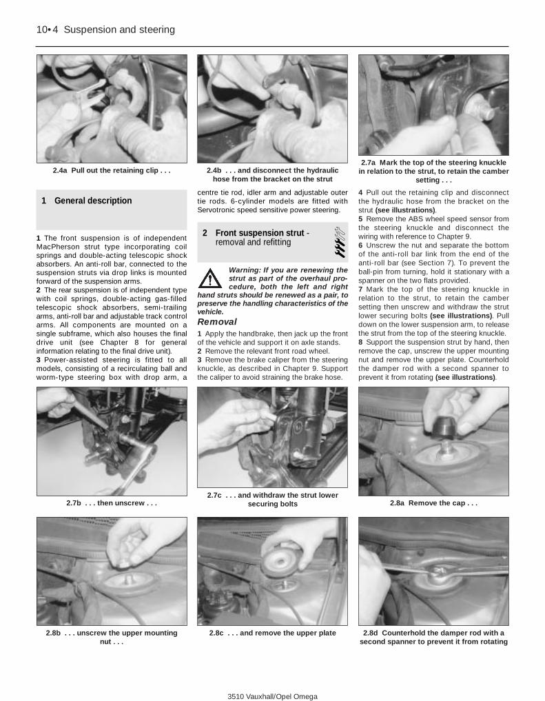
1 General description
1 The front suspension is of independentMacPherson strut type incorporating coilsprings and double-acting telescopic shockabsorbers. An anti-roll bar, connected to thesuspension struts via drop links is mountedforward of the suspension arms.2 The rear suspension is of independent typewith coil springs, double-acting gas-filledtelescopic shock absorbers, semi-trailingarms, anti-roll bar and adjustable track controlarms. All components are mounted on asingle subframe, which also houses the finaldrive unit (see Chapter 8 for generalinformation relating to the final drive unit).3 Power-assisted steering is fitted to allmodels, consisting of a recirculating ball andworm-type steering box with drop arm, a
centre tie rod, idler arm and adjustable outertie rods. 6-cylinder models are fitted withServotronic speed sensitive power steering.
2 Front suspension strut -removal and refitting 3
Warning: If you are renewing thestrut as part of the overhaul pro-cedure, both the left and right
hand struts should be renewed as a pair, topreserve the handling characteristics of thevehicle.Removal1 Apply the handbrake, then jack up the frontof the vehicle and support it on axle stands. 2 Remove the relevant front road wheel.3 Remove the brake caliper from the steeringknuckle, as described in Chapter 9. Supportthe caliper to avoid straining the brake hose.
4 Pull out the retaining clip and disconnectthe hydraulic hose from the bracket on thestrut (see illustrations).5 Remove the ABS wheel speed sensor fromthe steering knuckle and disconnect thewiring with reference to Chapter 9.6 Unscrew the nut and separate the bottomof the anti-roll bar link from the end of theanti-roll bar (see Section 7). To prevent theball-pin from turning, hold it stationary with aspanner on the two flats provided.7 Mark the top of the steering knuckle inrelation to the strut, to retain the cambersetting then unscrew and withdraw the strutlower securing bolts (see illustrations). Pulldown on the lower suspension arm, to releasethe strut from the top of the steering knuckle.8 Support the suspension strut by hand, thenremove the cap, unscrew the upper mountingnut and remove the upper plate. Counterholdthe damper rod with a second spanner toprevent it from rotating (see illustrations).
10•4 Suspension and steering
2.4a Pull out the retaining clip . . . 2.4b . . . and disconnect the hydraulichose from the bracket on the strut
2.7a Mark the top of the steering knucklein relation to the strut, to retain the camber
setting . . .
2.8b . . . unscrew the upper mounting nut . . .
2.8c . . . and remove the upper plate 2.8d Counterhold the damper rod with asecond spanner to prevent it from rotating
2.7b . . . then unscrew . . .2.7c . . . and withdraw the strut lower
securing bolts 2.8a Remove the cap . . .
3510 Vauxhall/Opel Omega

Warning: Do not unscrew thedamper rod nut (exposed by theremoval of the upper mounting
nut and plate) until spring compressorshave been fitted to the suspension strut.9 Pivot the lower end of the strut away fromthe wheel arch, then lower it away from theupper mounting and withdraw it from underthe vehicle (see illustration).
OverhaulNote: A purpose-made spring compressor isessential for this work. Use of makeshift orunsuitable tools may result in injury.10 Remove the strut as described in theprevious sub-Section. If required, mount it in avice with padded jaws.11 Fit the spring compressor and tighten itcompress the coil spring, unloading thepressure on the upper seat and mounting (seeillustration).12 Hold the piston rod stationary with anAllen key, then unscrew the damper rod nutand withdraw the washer (see illustrations).13 Remove the bearing and washer (notingits orientation), then slide off the upper springseat, upper rubber damper, bump stop rubberand dust cover from the damper rod and fromthe top of the coil spring. Extract the rubberdamper from the lower spring seat (seeillustrations).14 Lift off the coil spring together with thespring compressors.15 It is not possible to separate the shockabsorber from the strut body, so if the shockabsorber is faulty the strut assembly must be
renewed (in which case, the spring, uppermounting components, bushes, andassociated components can be transferred tothe new strut).16 With the strut assembly now dismantled,examine all the components for wear, damageor deformation. Check the rubbercomponents for deterioration. Renew any ofthe components as necessary.17 Examine the shock absorber for signs offluid leakage. Check the damper rod for signs ofwear or corrosion along its entire length, andcheck the strut body for signs of damage orcorrosion. While holding it in an upright position,test the operation of the strut by moving thedamper rod through a full stroke, and thenthrough short strokes of 50 to 100 mm. In bothcases, the resistance felt should be smooth andcontinuous. If the resistance is jerky, or uneven,or if there is any visible sign of wear or damageto the strut, renewal is necessary.
18 If any doubt exists about the condition ofthe coil spring, carefully release the springcompressors, and check the spring fordistortion and signs of cracking. Measure theunloaded height of the spring and compare itwith the figure listed in the Specifications.19 If a new shock absorber is being fitted,before reassembly push the damper rod fullyinto the shock absorber body, and thenextend the rod to end of its travel. Do thisthree or four times to ensure that the shockabsorber is fully primed.20 Refit the rubber damper to the lowerspring seat. Ensure that the coil spring iscompressed sufficiently to enable the uppermounting components to be fitted, then lowerthe coil spring (together with the springcompressors) onto the lower spring seat,ensuring that the lower end of the coil springabuts the stepped section of the rubberdamper (see illustrations).
Suspension and steering 10•5
10
2.9 Withdrawing the front suspension strutfrom the wheel arch
2.11 Fitting the spring compressor to thestrut coil spring
2.12a Hold the piston rod stationary withan Allen key . . .
2.13a Remove the bearing . . . 2.13b . . . and washer . . .
2.12b . . . then unscrew the damper rodnut . . .
2.12c . . . and withdraw the washer
2.13c . . . then slide off the upper springseat, upper rubber damper, bump stop
rubber and dust cover
3510 Vauxhall/Opel Omega

21 Locate the rubber damper in the upperspring seat, then slide the upper spring seat,bump stop rubber and dust cover over thedamper rod (see illustration).22 Ensure that the upper end of the coilspring abuts the stepped section of therubber damper.23 Fit the washer and strut bearing to thestrut damper rod and secure them in positionwith the washer and a new damper rod nut.Hold the damper rod stationary using an Allenkey and then tighten the nut to specifiedtorque. A crow’s foot adapter may be requiredto allow the damper rod to be held still as thenut is tightened.24 Slowly release the spring compressor andmake sure that the coil spring locatescorrectly on the damping rings.25 Refit the front suspension strut, asdescribed in the following sub-Section.
Refitting26 Commence refitting by inserting the strutup into the upper mounting. Refit the upperplate, then fit a new securing nut. Tighten thenut to the specified torque whilst holding thepiston rod stationary with an Allen key. Acrow’s foot adapter may be required to allowthe damper rod to be held still as the nut istightened.27 Fit the lower end of the strut to thesteering knuckle and insert a pair of newsecuring bolts, noting that the bolts areinserted from the front of the strut, so that theheads face front of the car. Ensure that thelower end of the strut is positioned according
to the markings made on the steering knuckleduring removal, to preserve the cambersetting, then fit the new nuts, and tightenthem to the specified torque.Note: If the original front wheel camber settinghas been lost, or if new struts are being fitted,the camber setting must be checked andadjusted, using a camber gauge, before thestrut lower nuts are tightened to their finaltorque setting; see Section 3 for details.28 Reconnect the drop link to the end of theanti-roll bar and tighten the nut to thespecified torque; see Section 7 for details.29 Refit the ABS wheel speed sensor andreconnect the cable, with reference toChapter 9.30 Press the brake hydraulic hose into thebracket on the strut and secure with the metalretaining clip. Refit the brake caliper withreference to Chapter 9.31 Refit the front wheel, then lower thevehicle to the ground and tighten the wheelbolts to the specified torque.32 Finally, have the front wheel toe-in adjust-ment checked and if necessary adjusted.
3 Front suspension camber -adjustment 5
1 After disturbing the front suspension strut orany of the front suspension components thathave an effect on wheel camber, the frontwheel camber setting must be checked, and ifnecessary adjusted, to preserve the vehicle’shandling characteristics and to prevent uneventyre wear. It is recommended that thisoperation is carried out by a Vauxhall dealer,who will have access to the necessarymeasuring equipment. However, the procedureis given here for reference.2 Apply the handbrake, select first gear orPark (as applicable) then jack up the front ofthe vehicle and support it on axle stands.3 Remove both front road wheels.4 Remove both brake calipers from thesteering knuckles, as described in Chapter 9.Support the calipers to avoid straining thebrake hoses.5 Working on one side of the vehicle, slackenand withdraw the front suspension strut lower
securing bolts. Fit two new securing bolts andnuts, noting that the bolts are fitted from thefront of the strut so that their heads face thefront of the car.6 Set the wheel to maximum positive camberby pressing the top of the brake disc inwards,towards the engine compartment. The strutlower mountings bolts will pivot on theirslotted mounting holes. Tighten the nuts toapproximately 20 Nm only, then refit the brakecaliper (see Chapter 9) and the road wheel.7 Repeat the operations in paragraphs 5 and6 on the opposite front wheel.8 Carefully lower the vehicle to the groundand tighten the road wheel bolts to thespecified torque.9 Load the vehicle to its specified adjustmentweight, as described in Specifications, Frontwheel alignment.10 Using a proprietary camber gauge, set thefront wheels to the specified camber angle.Adjustments are made by grasping the top ofthe road wheel and pivoting the steeringknuckle inwards or outwards to achieve thecorrect camber angle.11 When the correct camber angles areobtained, tighten the strut lower mounting nutsprogressively in two stages; first to 50 Nm,then to 90 Nm.12 Release the handbrake and select neutral,then rock the vehicle on its road wheels tosettle the suspension.13 Recheck the camber setting; if furtheradjustment is required, repeat the operationsdescribed in paragraphs 2 to 12 inclusive. Ifno further adjustment is required, tighten thestrut lower mounting nuts to their specifiedStage 1 and Stage 2 torque settings.
4 Front lower suspension arm- removal and refitting 3
Removal1 Apply the handbrake, then jack up the frontof the vehicle and support it on axle stands. 2 Remove the relevant front road wheel.3 Unscrew and remove the pinch-bolt, andpull down the lower suspension arm torelease the balljoint from the steering knuckle.4 Unscrew the vertical front mounting boltand the horizontal rear mounting bolt, discardthem, and withdraw the lower suspension armfrom under the vehicle. Note the horizontalbolt head faces towards the rear of the car.Note also that access to the front mountingbolt is via the top of the suspension subframeand access is very limited due to the proximityof the engine mounting bracket.5 Refer to Section 5 if renewing thesuspension balljoint. Examine the rubberbushes in the arm and if necessary renewthem using a hydraulic press. Note theorientation of the existing bushes in the lowerarm before pressing them out, and ensure thatthe new bushes are fitted in the same way.
10•6 Suspension and steering
2.20a Refit the rubber damper to the lowerspring seat
2.20b Lower the coil spring, together withthe spring compressors, onto the lower
spring seat
2.21 Locate the rubber damper in theupper spring seat
3510 Vauxhall/Opel Omega

Refitting6 Commence refitting by locating the arm onthe underbody and inserting the new mountingbolts. Do not re-use the old mounting bolts.Insert the front mounting bolt from back tofront, and insert the (shorter) rear mountingbolt from top to bottom.7 Hold the arm horizontally and tighten thesecuring nuts and bolts to the specifiedtorque.8 Insert the balljoint in the steering knuckleand fit a pinch-bolt, with its head facing therear of the vehicle. Fit a new nut and tighten tothe specified torque.9 Reconnect the links to the anti-roll bar andtighten the nuts.
10 Refit the front wheel and lower the vehicleto the ground.11 Finally, have the front wheel alignmentchecked and if necessary adjusted.
5 Front suspension lower balljoint -renewal
31 Remove the front lower suspension arm asdescribed in Section 4.2 The balljoint is riveted to the suspensionarm when new, with subsequent balljointsbolted on. Where necessary drill out the rivetsusing a 12.0 mm drill. One side of each rivethas a centre punch to facilitate accuratedrilling in order to prevent enlarging the holesin the arm (see illustration).3 Coat the newly-drilled holes with a suitablerust-preventing agent.4 Using only the special bolts supplied thenew balljoint, fit the balljoint and tighten thenuts to the specified torque. The nuts mustface downwards.5 Refit the front lower suspension arm withreference to Section 4.
6 Front anti-roll bar -removal and refitting 3
Removal1 Apply the handbrake, then jack up the frontof the vehicle and support it on axle stands.Remove the front wheels.2 Unscrew the nuts and separate the lowerends of the drop links from the ends of theanti-roll bar (see Section 7). Prevent the linkball-pins from turning by holding them with aspanner on the two flats provided.3 Refer to Section 10 and remove the frontsuspension subframe.4 From inside the engine compartmentunscrew the anti-roll bar mounting clampbolts, and unclip the clamps (seeillustration).5 Withdraw the anti-roll bar from under thevehicle.
Refitting6 Examine the mounting rubbers for wear anddeterioration and, if necessary, prise themfrom the bar. Coat the new rubbers with asilicone-based spray and fit them on the barwith their slits facing towards the rear of thevehicle.7 Insert the anti-roll bar from under the frontof the vehicle, and refit the clamps. Insert thebolts loosely.8 Reconnect the drop links to the ends of theanti-roll bar; use new securing nuts andtighten them to the specified torque.9 Tighten the anti-roll bar mounting clampbolts to the specified torque.10 Refit the front wheels and lower thevehicle to the ground.
7 Front anti-roll bar drop link -removal and refitting 2
Removal1 Apply the handbrake, then jack up the frontof the vehicle and support it on axle stands.Remove the appropriate front wheel.2 Note which way round the link is fitted thenunscrew the nuts while holding the ball-pinswith a spanner on the two flats provided (seeillustrations).3 Remove the link from the strut and anti-rollbar.
Suspension and steering 10•7
10
7.2b . . . and detach the drop link from thesuspension strut
7.2a Unscrew the upper nut . . .
6.4 Unscrew the anti-roll bar mountingclamp bolts (arrowed)
5.2 Drilling out the front suspension lowerballjoint rivets
7.2c Detach the drop link from the anti-rollbar
7.2d Counterhold the drop link stud usingthe flats provided
3510 Vauxhall/Opel Omega
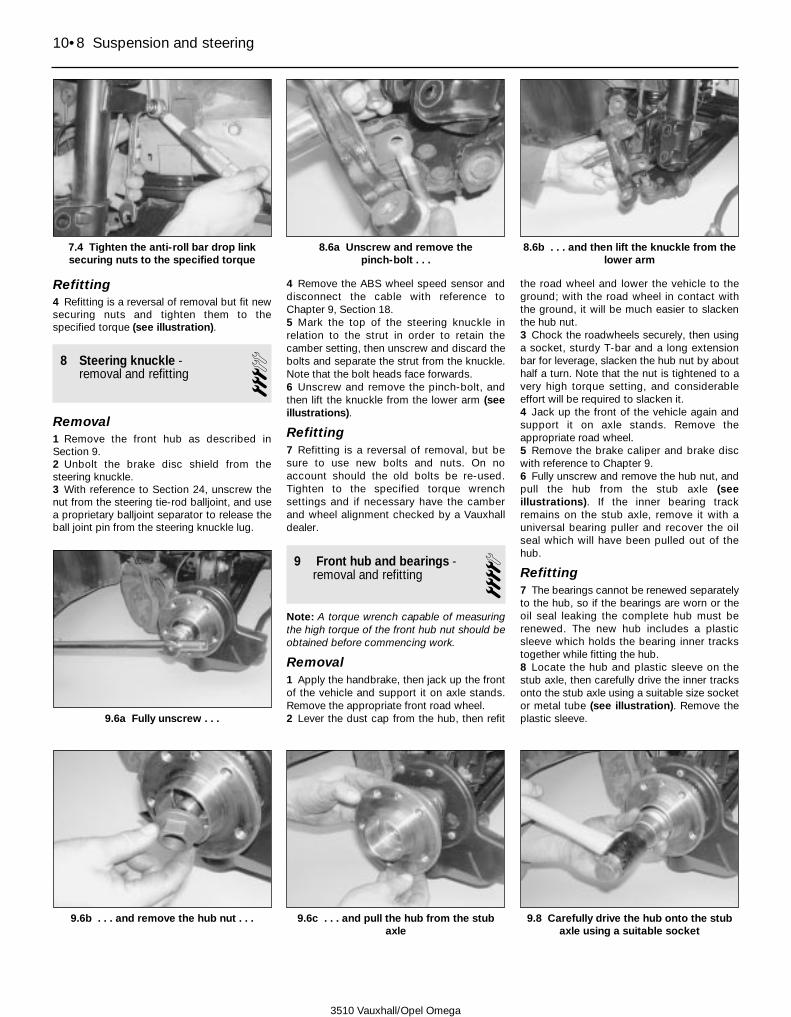
Refitting4 Refitting is a reversal of removal but fit newsecuring nuts and tighten them to thespecified torque (see illustration).
8 Steering knuckle -removal and refitting 3
Removal1 Remove the front hub as described inSection 9.2 Unbolt the brake disc shield from thesteering knuckle.3 With reference to Section 24, unscrew thenut from the steering tie-rod balljoint, and usea proprietary balljoint separator to release theball joint pin from the steering knuckle lug.
4 Remove the ABS wheel speed sensor anddisconnect the cable with reference toChapter 9, Section 18.5 Mark the top of the steering knuckle inrelation to the strut in order to retain thecamber setting, then unscrew and discard thebolts and separate the strut from the knuckle.Note that the bolt heads face forwards.6 Unscrew and remove the pinch-bolt, andthen lift the knuckle from the lower arm (seeillustrations).
Refitting7 Refitting is a reversal of removal, but besure to use new bolts and nuts. On noaccount should the old bolts be re-used.Tighten to the specified torque wrenchsettings and if necessary have the camberand wheel alignment checked by a Vauxhalldealer.
9 Front hub and bearings -removal and refitting 4
Note: A torque wrench capable of measuringthe high torque of the front hub nut should beobtained before commencing work.
Removal1 Apply the handbrake, then jack up the frontof the vehicle and support it on axle stands.Remove the appropriate front road wheel.2 Lever the dust cap from the hub, then refit
the road wheel and lower the vehicle to theground; with the road wheel in contact withthe ground, it will be much easier to slackenthe hub nut.3 Chock the roadwheels securely, then usinga socket, sturdy T-bar and a long extensionbar for leverage, slacken the hub nut by abouthalf a turn. Note that the nut is tightened to avery high torque setting, and considerableeffort will be required to slacken it.4 Jack up the front of the vehicle again andsupport it on axle stands. Remove theappropriate road wheel.5 Remove the brake caliper and brake discwith reference to Chapter 9.6 Fully unscrew and remove the hub nut, andpull the hub from the stub axle (seeillustrations). If the inner bearing trackremains on the stub axle, remove it with auniversal bearing puller and recover the oilseal which will have been pulled out of thehub.
Refitting7 The bearings cannot be renewed separatelyto the hub, so if the bearings are worn or theoil seal leaking the complete hub must berenewed. The new hub includes a plasticsleeve which holds the bearing inner trackstogether while fitting the hub.8 Locate the hub and plastic sleeve on thestub axle, then carefully drive the inner tracksonto the stub axle using a suitable size socketor metal tube (see illustration). Remove theplastic sleeve.
10•8 Suspension and steering
7.4 Tighten the anti-roll bar drop linksecuring nuts to the specified torque
8.6a Unscrew and remove the pinch-bolt . . .
8.6b . . . and then lift the knuckle from thelower arm
9.6b . . . and remove the hub nut . . .
9.6a Fully unscrew . . .
9.6c . . . and pull the hub from the stubaxle
9.8 Carefully drive the hub onto the stubaxle using a suitable socket
3510 Vauxhall/Opel Omega

Refitting9 Refit the components in the reverse orderto removal, noting the following points (seeillustration):a) Tighten all nuts and bolts to the specified
torque.b) Use a new hub nut and ensure that it
tightened to the specified torquec) Refit the brake disc and caliper as
described in Chapter 9.d) Fit a new hub dust cap.
10 Front suspension subframe -removal and refitting 3
Removal1 Apply the handbrake, then jack up the frontof the vehicle and support it securely on axlestands. Unscrew the fixings and lower thecover panel away from the underside of theengine compartment.2 On models with Xenon headlamps, unplugthe wiring from the front vehicle level sensor;refer to Chapter 12, Section 13 for details.3 Unbolt both lower suspension arm balljointsfrom the base of each steering knuckle, asdescribed in Section 4.4 Unbolt the anti-roll bar drop links from theends of the anti-roll bar, as described inSection 7.5 Unscrew the nuts securing both enginemountings to the subframe and enginebrackets, with reference to Chapter 2A. Whereapplicable, also unbolt the engine vibrationdamper strut from the subframe.6 Position an engine hoist or lifting beam overthe engine compartment. Attach the lifting jibto the engine lifting eyelets at the side of thecylinder head(s) and raise it to take the weightof the engine.7 Mark the relationship between thesubframe and underbody using a marker pento ensure correct alignment on refitting.8 Support the weight of the subframe using atrolley jack and a stout length of wood.9 Identify the six subframe mounting bolts forposition. Progressively slacken and removethe bolts, noting that they are of different
lengths and diameters, then lower thesubframe to the ground using the trolley jack.
Refitting10 Refitting is a reversal of removal, notingthe following points:a) Refit the subframe according to the
alignment markings made during removal.b) Fit new subframe securing bolts..c) Tighten all nuts and bolts to the correct
torque, where specified.d) On completion have the front wheel
alignment (see Section 27) and cambersetting (see Section 3) checked and ifnecessary corrected.
11 Rear shock absorber -removal and refitting 3
Note: Shock absorbers should always berenewed as a pair, to preserve the handlingcharacteristics of the vehicle.
Removal1 Chock the front wheels, then jack up therear of vehicle and support it securely on axlestands.2 Raise the relevant semi-trailing arm using atrolley jack to relieve the load on the shockabsorber.3 On Saloon models, remove the trim panelfrom the side of the boot space, then prise therubber cap from the top of the shock absorberupper mounting.
4 On Estate models, fold back the load spacecarpet, then remove the screws and lift off thecover to expose the shock absorber uppermountings.5 Unscrew the upper mounting nuts andremove the washer and rubber buffers (seeillustration).6 On models fitted with rear suspensionlevel control, reach in through the rear wheelarch and release the air pressure from thevalve on the side of the shock absorberbody. Release the clip and disconnect thepressure line from the shock absorber.7 Lower the semi-trailing arm using the trolleyjack, then unscrew the lower mounting boltand washer, then remove the shock absorber(see illustrations).8 With the shock absorber removed, examineit for wear, damage or deformation. Check therubber mounting components fordeterioration. Renew any of the componentsas necessary.9 Examine the shock absorber for signs offluid leakage. Check the damper rod for signsof wear or corrosion along its entire length,and check the strut body for signs of damageor corrosion. While holding it in an uprightposition, test the operation of the shockabsorber by moving the damper rod throughone or two full strokes, and then through shortstrokes of about 50 to 100 mm. In both cases,the resistance felt should be smooth andcontinuous. If the resistance is jerky, oruneven, or if there is any visible sign of wearor damage to the strut, renewal is necessary.10 If a new shock absorber is being fitted,before reassembly push the damper rod fullyinto the shock absorber body, and then pullthe rod out to end of its travel. Do this three orfour times to ensure that the shock absorberis fully primed.
Refitting11 Commence refitting by locating the shockabsorber on the semi trailing arm andinserting the bottom mounting bolt loosely.Ensure that the bush engages with the recessin the lower mounting.12 Raise the semi-trailing arm using a trolleyjack and guide the top of the shock absorberthrough its upper wheel arch mountings.
Suspension and steering 10•9
10
9.9 Fitting a new hub dust cap
11.5 Unscrew the rear shock absorberupper mounting nut
11.7a Unscrew the rear shock absorberlower mounting bolt and washer . . .
11.7b . . . then remove the shock absorberfrom the wheel arch
3510 Vauxhall/Opel Omega

13 On models with rear suspension levelcontrol, charge the shock absorber slightly withcompressed air. An exact initial pressure is notspecified by the manufacturer but carefullyinflate the shock absorber until it protrudesthrough the upper mountings. Refit the pressureline to the shock absorber valve and secure it inposition with the retaining clip. Ensure that thepressure line is positioned so that it does notfoul any suspension components.14 Refit the upper mounting rubber buffersand washer. Fit a new securing nut andtighten it to the specified torque.15 Tighten the lower shock absorbermounting bolt to the specified torque.16 On estate models, refit the cover paneland secure it position with the screws.17 On Saloon models, press the rubber caponto the top of the shock absorber.18 Refit the road wheels and lower thevehicle to the ground.19 Carry out a check of the rear suspensionlevel control system’s operation, whereapplicable.
12 Rear semi-trailing arm -removal and refitting 3
Removal1 Chock the front wheels, then jack up therear of the vehicle and support on axle standspositioned under the subframe mountings.2 With reference to Chapter 8, Section 8,unbolt the relevant driveshaft from the rearhub and support it to one side.3 Disconnect the hydraulic brake hose fromthe bracket on the semi-trailing arm.4 Remove the rear brake caliper and brakedisc as described in Chapter 9.5 Unhook the return spring and disconnectthe handbrake cable from the lever on thesemi-trailing arm. Disconnect the cable fromthe bracket.6 On models with rear suspension levelcontrol, unplug the wiring from the rearvehicle level sensor. Mark the relationshipbetween the level sensor actuator arm and theanti-roll bar drop link, to ensure correctalignment on refitting, then prise the link rodfrom the balljoint on the sensor actuator arm.7 Using a socket through the unthreadedholes in the hub unscrew the brake anchorplate bolts and remove the locking plate.8 Remove the rear hub with reference toSection 20, then withdraw the brake anchorplate and brake shoes as an assembly.9 Unbolt the track control arm from the semi-trailing arm, with reference to Section 15.10 With reference to Chapter 4A, disconnectthe mounting rubbers from the exhaustsystem intermediate and rear silencers, thenlower the exhaust system away from thefloorpan by approximately 30 cm. Support theexhaust in this position with wire or nyloncable ties.
11 Unbolt the rear anti-roll bar drop link fromthe semi-trailing arm. Pivot the link upwardsto keep it clear of the work area.12 Raise the semi-trailing arm slightly using atrolley jack, to relieve the load on the shockabsorber.13 On models fitted with rear suspensionlevel control, release the air pressure via theshock absorber valve by disconnecting thepressure line from the shock absorber (seeSection 11).14 Unscrew and withdraw the shockabsorber lower mounting bolt with referenceto Section 11.15 Lower the semi-trailing arm using thetrolley jack until the rear coil spring anddamping rubbers can be removed (seeSection 13).16 Position a trolley jack underneath the finaldrive unit, the raise the jack head until it is justsupport the weight of the unit.17 Remove the heat shield panels, then withreference to Chapter 8, unbolt the propellershaft centre bearing support bracket from theunderbody. Support the propeller shaft on anaxle stand.18 Slacken and remove the bolts securingthe leading edge of the rear subframe to thefloorpan. Lower the final drive unit andsubframe slightly, using the trolley jack, untilthe semi-trailing arm bolts are accessible.19 Slacken and withdraw the pivot bolts andremove the semi-trailing arm from the subframe.20 If the pivot bushes are worn, they may berenewed. Cut the shoulders from the oldbushes and press them from the semi-trailingarm using a hydraulic press. Fit the newbushes in a similar way, but dip them in soapywater first to assist fitting. Note that the plastic-coated bush, nearest the final drive unit, isfitted with its collar facing the final drive unit.
Refitting21 Refitting is a reversal of removal, notingthe following points.a) Tighten all nuts and bolts to the specified
torque.b) The semi-trailing arm pivot bolt must be
inserted such that their heads face awayfrom final drive unit.
c) On vehicles with rear suspension levelcontrol, refit the level sensor connectingrod with respect to the alignmentmarkings made during removal.
d) When reconnecting the pressure line tothe shock absorber on models with rearsuspension level control, ensure that theline cannot be fouled by any of thesuspension components.
e) On models with Xenon headlamps, recon-nect the wiring to the vehicle level sensor.
22 On completion adjust the handbrake withreference to Chapter 1, then have the rearwheel alignment checked and if necessaryadjusted by a Vauxhall dealer. On models withXenon headlamps, it is also recommendedthat the headlight beam alignment is checkedby a Vauxhall dealer.
13 Rear coil spring -removal and refitting 3
Note: Suspension coil springs should alwaysbe renewed as a matched pair, to preserve thehandling characteristics of the vehicle.
Removal1 Chock the front wheels, then jack up therear of the vehicle and support on axle stands.Remove the relevant rear wheel.2 Disconnect the hydraulic brake hose fromthe bracket on the semi-trailing arm by pullingout the locking plate.3 With reference to Chapter 4A, disconnectthe mounting rubbers from the exhaustsystem intermediate and rear silencers, thenlower the exhaust system away from thefloorpan by approximately 30 cm. Support theexhaust in this position with wire or nyloncable ties.4 On models with rear suspension levelcontrol, unplug the wiring from the rearvehicle level sensor. Mark the relationshipbetween the level sensor actuator arm and theanti-roll bar drop link, to ensure correctalignment on refitting, then prise the link rodfrom the balljoint on the sensor actuator arm.5 Using a trolley jack, slightly raise thesemi-trailing arm to relieve the load on theshock absorber.6 On models fitted with rear suspension levelcontrol, release the air pressure via the shockabsorber valve by disconnecting the pressureline from the shock absorber (see Section 11).7 Unbolt the lower end of the shock absorberwith reference to Section 11.8 Unclip the ABS rear wheel speed sensorcables from the underbody, then unplug thecables from the sensor at the connectors; seeChapter 9 for details.9 Using a trolley jack, support the final driveunit then unbolt the subframe rear dampingbrackets from the underbody (see Section 19).10 Lower the final drive unit, subframe andsemi-trailing arm until the rear coil spring anddamping rubbers can be removed. Note thatthe upper damping rubber incorporates abuffer.
Refitting11 Refitting is a reversal of removal, notingthe following points.
a) When refitting the coil spring, ensure thatthe end face of the top of the coil is facingthe rear of the vehicle.
b) Tighten all nuts and bolts to the specifiedtorques.
c) On vehicles with rear suspension levelcontrol, refit the level sensor connectingrod with respect to the alignmentmarkings made during removal.
d) Refit the ABS wheel speed sensors withreference to Chapter 9.
10•10 Suspension and steering
3510 Vauxhall/Opel Omega

14 Rear anti-roll bar -removal and refitting 3
Removal1 Chock the front wheels, then jack up therear of the vehicle and support securely onaxle stands.2 On models with rear suspension levelcontrol, mark the relationship between thelevel sensor actuator arm and the anti-roll bardrop link, to ensure correct alignment onrefitting, then prise the link rod from theballjoint on the sensor actuator arm.3 Disconnect the wiring from the ABS wheelspeed sensors, then release the wiring fromthe clips on the rear subframe.4 Unbolt the two anti-roll bar drop links fromthe ends semi-trailing arms, and remove therubber mountings (see illustration).5 Support the final drive unit on a trolley jack.Unbolt the subframe rear damping bracketsfrom the underbody, then lower the final driveunit slightly, until access to the anti-roll barmounting clamp bolts can be gained.6 Unscrew the clamp bolts from the top ofthe subframe and release the clamps from theanti-roll bar. Pass the anti-roll bar over therear of the subframe and withdraw it togetherwith its drop links from under the vehicle.7 Unbolt the drop links from the anti-roll bar.If necessary, the clamp mounting rubbersmay be pressed from the links and renewed,using a hydraulic press. Dip the new rubbersin soapy water to assist fitting them.
Refitting8 Refitting is a reversal of removal, but tightenall nuts and bolts to their correct torques,where specified.
15 Rear track control arm -removal and refitting 3
Removal1 Chock the front wheels, then jack up therear of the vehicle and support securely onaxle stands.2 Unscrew the nut securing the track controlarm to the semi-trailing arm (see illustration).Disconnect the rod from the arm using aproprietary ball joint separator.3 Unbolt the track control arm from thesubframe (see illustration), and remove thearm from the vehicle.4 If the track control arm is to be dismantled,first measure its overall length to obtain anapproximate rear wheel alignment settingafter refitting.
Refitting5 Refit the track control arm by following theremoval procedure in reverse, using new
nuts/bolts where indicated in the Specifications.Tighten all fixings to the specified torque. Oncompletion, have the rear wheel alignmentchecked and if necessary adjusted by aVauxhall dealer.
16 Rear suspension levelcontrol system - componentremoval and refitting
3Compressor
Removal1 The compressor is located in the right handfront wheel arch. To gain access, raise thefront of the vehicle and rest it securely on axlestands. Remove the right hand roadwheel, theunscrew the fixings and detach the liner fromthe right hand wheel arch.2 Unplug the wiring connector from thecompressor.3 Disconnect the air intake hose from thecavity behind the right hand headlight unit.4 Release the securing clip and detach the airpressure pipe from the top of the compressor.5 Slacken and withdraw the securing screwsthen remove the compressor together with itsmounting bracket from the bodywork.
Refitting6 Refitting is a reversal of removal. Oncompletion, check the operation of the levelcontrol system as described in the last sub-Section.
Pressure line
Removal7 Disconnect the pressure line from thecompressor as described in the previous sub-Section.8 Raise the rear of the vehicle and rest itsecurely on axle stands.9 Release the metal spring clip anddisconnect the pressure line from the valve onthe side of the first rear shock absorber.Disconnect the pressure pipe from theopposite shock absorber in a similar manner.10 Locate the pressure T-piece which ismounted on vehicle underbody. Release theclips and disconnect the pressure pipe fromthe T-piece.11 Work along the underside of the vehicle,releasing the pressure pipe from its securingclips, then remove the pipe from the vehicle.
Refitting12 Refitting is a reversal of removal. Whenrefitting the pressure pipes to the rear shockabsorbers, ensure that they are positionedsuch that they cannot be fouled by the rearsuspension components. On completion,check the operation of the level controlsystem as described in the last sub-Section.
Level sensor
Removal13 Disconnect the battery negative cable andposition it away from the terminal.14 Chock the front wheels, then raise the rearof the vehicle and support it securely on axlestands. Remove the rear road wheels.15 Unplug the wiring from the level sensor atthe multiway connector.16 Prise the connecting rod from the balljointon the sensor’s actuator arm.17 Undo the securing screws and remove thesensor together with its bracket from thesubframe.
Refitting18 Refitting is a reversal of removal. Oncompletion, check the operation of the levelcontrol system as described in the next sub-Section.
System operation check19 Park the vehicle (unloaded) on level
Suspension and steering 10•11
10
14.4 Rear anti-roll bar-to-drop link bolt
15.2 Track control arm-to-semi-trailingarm bolt
15.3 Track control arm-to-subframe bolt
3510 Vauxhall/Opel Omega
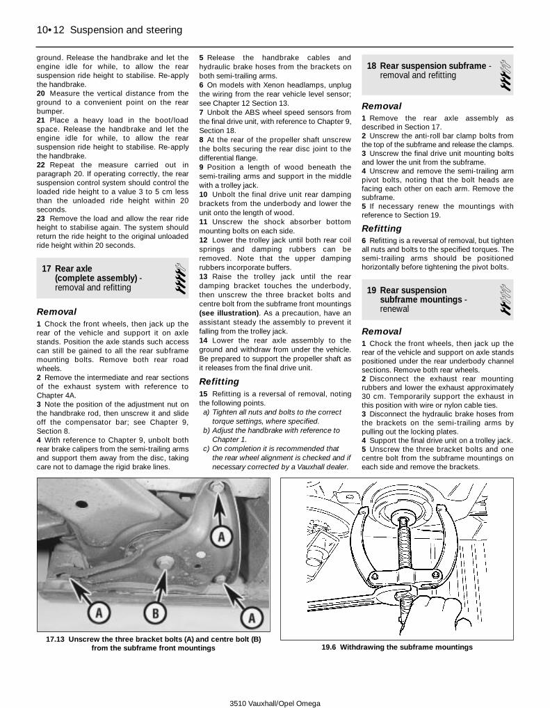
ground. Release the handbrake and let theengine idle for while, to allow the rearsuspension ride height to stabilise. Re-applythe handbrake.20 Measure the vertical distance from theground to a convenient point on the rearbumper.21 Place a heavy load in the boot/loadspace. Release the handbrake and let theengine idle for while, to allow the rearsuspension ride height to stabilise. Re-applythe handbrake.22 Repeat the measure carried out inparagraph 20. If operating correctly, the rearsuspension control system should control theloaded ride height to a value 3 to 5 cm lessthan the unloaded ride height within 20seconds.23 Remove the load and allow the rear rideheight to stabilise again. The system shouldreturn the ride height to the original unloadedride height within 20 seconds.
17 Rear axle (complete assembly) -removal and refitting
4Removal1 Chock the front wheels, then jack up therear of the vehicle and support it on axlestands. Position the axle stands such accesscan still be gained to all the rear subframemounting bolts. Remove both rear roadwheels.2 Remove the intermediate and rear sectionsof the exhaust system with reference toChapter 4A.3 Note the position of the adjustment nut onthe handbrake rod, then unscrew it and slideoff the compensator bar; see Chapter 9,Section 8.4 With reference to Chapter 9, unbolt bothrear brake calipers from the semi-trailing armsand support them away from the disc, takingcare not to damage the rigid brake lines.
5 Release the handbrake cables andhydraulic brake hoses from the brackets onboth semi-trailing arms.6 On models with Xenon headlamps, unplugthe wiring from the rear vehicle level sensor;see Chapter 12 Section 13.7 Unbolt the ABS wheel speed sensors fromthe final drive unit, with reference to Chapter 9,Section 18.8 At the rear of the propeller shaft unscrewthe bolts securing the rear disc joint to thedifferential flange.9 Position a length of wood beneath thesemi-trailing arms and support in the middlewith a trolley jack.10 Unbolt the final drive unit rear dampingbrackets from the underbody and lower theunit onto the length of wood.11 Unscrew the shock absorber bottommounting bolts on each side.12 Lower the trolley jack until both rear coilsprings and damping rubbers can beremoved. Note that the upper dampingrubbers incorporate buffers.13 Raise the trolley jack until the reardamping bracket touches the underbody,then unscrew the three bracket bolts andcentre bolt from the subframe front mountings(see illustration). As a precaution, have anassistant steady the assembly to prevent itfalling from the trolley jack.14 Lower the rear axle assembly to theground and withdraw from under the vehicle.Be prepared to support the propeller shaft asit releases from the final drive unit.
Refitting15 Refitting is a reversal of removal, notingthe following points.a) Tighten all nuts and bolts to the correct
torque settings, where specified.b) Adjust the handbrake with reference to
Chapter 1.c) On completion it is recommended that
the rear wheel alignment is checked and ifnecessary corrected by a Vauxhall dealer.
18 Rear suspension subframe -removal and refitting 3
Removal1 Remove the rear axle assembly asdescribed in Section 17.2 Unscrew the anti-roll bar clamp bolts fromthe top of the subframe and release the clamps.3 Unscrew the final drive unit mounting boltsand lower the unit from the subframe.4 Unscrew and remove the semi-trailing armpivot bolts, noting that the bolt heads arefacing each other on each arm. Remove thesubframe.5 If necessary renew the mountings withreference to Section 19.
Refitting6 Refitting is a reversal of removal, but tightenall nuts and bolts to the specified torques. Thesemi-trailing arms should be positionedhorizontally before tightening the pivot bolts.
19 Rear suspension subframe mountings -renewal
2Removal1 Chock the front wheels, then jack up therear of the vehicle and support on axle standspositioned under the rear underbody channelsections. Remove both rear wheels.2 Disconnect the exhaust rear mountingrubbers and lower the exhaust approximately30 cm. Temporarily support the exhaust inthis position with wire or nylon cable ties.3 Disconnect the hydraulic brake hoses fromthe brackets on the semi-trailing arms bypulling out the locking plates.4 Support the final drive unit on a trolley jack.5 Unscrew the three bracket bolts and onecentre bolt from the subframe mountings oneach side and remove the brackets.
10•12 Suspension and steering
3510 Vauxhall/Opel Omega
17.13 Unscrew the three bracket bolts (A) and centre bolt (B)from the subframe front mountings 19.6 Withdrawing the subframe mountings

6 The mountings must now be pulled from thesubframe. The Vauxhall tool for this task isshown in (see illustration). The subframe islowered slightly and the mounting bolt insertedfrom the top, then the puller is assembled asshown and the nut tightened to withdraw themounting. If a similar arrangement using aconventional puller is not possible, use metaltubing, a long bolt, and large washers or ametal plate to remove the mounting.7 The Vauxhall tool for inserting themountings is shown in (see illustration), andhere again a similar tool may be fabricatedfrom metal plate and a long bolt.
Refitting8 Refitting is a reversal of removal.
20 Rear hub and bearing -removal and refitting 4
Note: A torque wrench capable of measuringthe high torque of the rear hub nut should beobtained before commencing work. If such atorque wrench is not available, it isrecommended that the work is entrusted to aVauxhall dealer.
Removal1 Chock the front wheels, then jack up the rearof the vehicle and support it on axle stands.2 Unscrew the socket-head bolts securingthe driveshaft to the rear hub while holding therear wheel stationary. Recover the lock-washers.3 Lever the driveshaft from the rear hub andsupport it to one side.4 Remove the rear wheel.5 Disconnect the hydraulic brake hose fromthe bracket on the semi-trailing arm by pullingout the locking plate.6 Unbolt and remove the brake caliper andsupport it to one side without straining thehydraulic brake hose Unscrew the retainingscrew and remove the brake disc. Refer toChapter 9 for details of both operations.7 Refer to Chapter 10 and unbolt the shockabsorber lower mounting bolt from thesemi-trailing arm. Support the semi-trailingarm on the head of a trolley jack.8 Using an Allen key through an unthreadedhole in the hub drive flange, unscrew thebrake backplate mounting bolts. Note that theupper bolts are shorter and are fitted with alocking plate.9 Insert the wheel bolts and use a long bar tohold the hub stationary, then remove thelocking plate and unscrew the central hub-securing nut (exposed by the removal ofdriveshaft) from the rearward-facing surfaceof the hub (see illustration).10 Pull off the driveshaft flange using asuitable puller.11 Press the rear hub outwards from thebearing using a suitable puller bolted to thesemi-trailing arm.
12 Extract the circlip from the semi-trailingarm then press out the bearing, again using abearing puller bolted to the arm.13 If the inner bearing track has remained onthe hub remove it with a bearing puller.14 Clean all the components and examinethem for wear and damage. Obtain a newbearing.
Refitting15 Press the new bearing into thesemi-trailing arm using pressure on the outertrack. If necessary, a long bolt and a selectionof flat washers may be used to do this.16 Fit the bearing retaining circlip.17 Support the wheel bearing inner track onthe inside with a metal tube, then carefullydrive in the rear hub from the outside.18 Fit the driveshaft flange on the inside ofthe hub. If necessary, support the outside ofthe hub and drive the flange fully on from theinside.19 Refit the hub nut and tighten to thespecified torque while holding the hubstationary. Drive in the special locking plate tosecure the nut in position.20 The remainder of the refitting procedure isa reversal of removal, but note the followingpoints.a) Tighten all nuts and bolts to the specified
torque wrench settingsb) Adjust the handbrake with reference to
Chapter 1.
21 Steering wheel -removal and refitting 3
Models without driver’s airbag
Removal1 Disconnect the battery negative lead.2 Set the front wheels in the straight-aheadposition.3 Prise the horn pad from the centre of thesteering wheel and disconnect the two wires.4 With the ignition key inserted check that thesteering lock is disengaged.5 Bend back the locktab and unscrew theretaining nut. Remove the locktab.6 Mark the inner column and steering wheelin relation to each other then remove thesteering wheel by carefully rocking it from sideto side. Do not use a hammer or mallet toremove it.7 If necessary, unclip the horn contact ringfrom the steering wheel, noting that thedirection indicator return segment points tothe left.8 Check that the spring is located on theinner column, and lightly lubricate the horncontact finger with a copper-based grease.
Refitting9 Refitting is a reversal of removal, but tightenthe nut to the specified torque and bend upthe locktab to lock the nut in position.
Models with driver’s airbagWarning: Refer to theSupplementary Restraint System(SRS) precautions given inChapter 12 before disturbing thedriver’s airbag.
Removal10 Before removing the driver’s airbag, carryout the following operations: disconnect thenegative cable from the battery and position itclear of the terminal. Wait at least one minutebefore proceeding, to allow the SRS controlunit capacitor to discharge. Failure to observethese steps may result in accidentaldetonation of the airbag.11 Remove the driver’s airbag from thesteering wheel, as described in Chapter 12,Section 24: Supplementary Restraint System(SRS) components - removal and refitting.12 Set the steering wheel in the straightahead position, then remove the ignition keyand allow the steering column lock to engage.Ensure that the steering column remains inthis position throughout the entire procedure.13 Mark the relationship between thesteering wheel and column to ensure correctalignment on refitting.14 Unplug the horn button wiring at themultiway connector. Where applicable, alsounplug the audio remote control button wiring(see illustration).
Suspension and steering 10•13
10
19.7 Pressing in the subframe mountings
20.9 Driveshaft flange and rear hub nut
3510 Vauxhall/Opel Omega

15 Bend back the locktab and then unscrewthe steering wheel retaining nut. Remove thelocktab (see illustrations).16 Remove the steering wheel from thesteering column by carefully rocking it fromside to side. Do not use a hammer or mallet toremove it. Guide the horn and audio controlwiring through the aperture at the centre ofthe steering wheel (see illustrations).
Refitting17 Refitting is a reversal of removal, buttighten the nut to the specified torque andbend up the locktab to lock the nut inposition. Refit the driver’s airbag withreference to Chapter 12, Section 24:Supplementary Restraint System (SRS)components - removal and refitting.
22 Steering column -removal and refitting 4
Removal 1 Park the vehicle on level ground with thesteering wheel turned to the straight-aheadposition. Disconnect the battery negativelead.2 Working in the driver’s footwell, release theclip and screws and detach the lower trimpanel from underside of the facia. Mark theinner section of the steering column in relation
to the flexible joint, then unscrew and removethe upper clamp bolt, to separate the end ofthe inner section of the steering column fromthe flexible joint (see illustration).3 Remove the steering wheel as described inSection 21. On models fitted with a driver’sairbag, remove the airbag contact unit, withreference to Chapter 12, Section 24.
Warning: Refer to the precautionsgiven in Chapter 12 beforedisturbing the any of Supple-
mentary Restraint System (SRS) com-ponents.
4 Where applicable, unscrew the shaft fromsteering column height adjustment lever.5 Remove the screws and withdraw theupper and lower shroud panels from thesteering column.6 Remove the steering column lock cylinderwith reference to Section 23.7 Remove the ignition switch contact unitwith reference to Section 23.8 Depress the locking clips and remove thestalk switch units from the steering column;refer to Chapter 12, Section 4.9 At the lower edge of the facia, below thesteering column, release the securing clip andhinge the access panel downwards away fromthe fuse box and relay box. Remove thescrews, unhook the check strap and removethe lid from the facia.10 Slacken and withdraw the securingscrews, then release the fuse box and relaybox from the facia, leaving the wiringharnesses connected.
10•14 Suspension and steering
21.14 Unplug the horn button/audiocontrol wiring at the multiway connector(s)
21.15a Bend back the locktab . . . 21.15b . . . and then slacken . . .
21.16a Remove the steering wheel fromthe steering column
22.2 Unscrew and remove the upperclamp bolt (arrowed) to separate the inner
section of the steering column from theflexible joint
21.15c . . . and remove the steering wheelretaining nut . . .
21.15d . . . and remove the locktab
21.16b If necessary, use a proprietarysteering wheel puller to assist removal
3510 Vauxhall/Opel Omega

11 The upper column mounting consists of anut and a shear bolt (see illustration). Ideallya bolt extractor should be used to remove theshear bolt by first drilling a 3.2 mm hole thenusing the extractor to unscrew the bolt.Alternatively, drill off the head and use grips tounscrew the remainder of the bolt later.12 Unscrew the upper mounting nut andwithdraw the steering column rearwards fromthe flexible coupling. The column should behandled carefully to avoid damage to thelatticed safety outer column and special innercolumn.
Refitting13 Refitting is a reversal of removal buttighten all nuts and bolts to the specifiedtorque. Before tightening the shear bolt,check that the column is correctly alignedthen tighten the bolt until the head shears off.Check that, with the front wheels in thestraight-ahead position, the steering wheelspokes are centred. Before tightening theclamp bolt, check that the steering column isnot stressed, then tighten the bolt to thespecified torque. Make sure that the switchrubber grommets are correctly located in theupper shroud.
23 Steering columnlock/ignition switch - removal and refitting 3
Lock cylinder
Removal1 Remove the steering wheel as described inSection 21.2 Slacken and withdraw the screws, thendetach the upper lower sections of the shroudpanelling from the steering column.3 Unplug the wiring and slide the immobiliserreceiver from the lock cylinder housing (seeillustration).4 Insert the ignition key into the lock cylinderand turn it to position I.5 Depress the recessed locking button with asuitable tool and withdraw the lock cylinder,together with the key from, from the housing(see illustrations).
Refitting6 Before inserting the lock cylinder into itshousing, check that the steering lock bolt hasnot engaged; if this is the case, it will not be
possible to fully insert the lock cylinder into thehousing. Correct this condition by inserting aflat bladed screwdriver into the housing andpressing the locking button latch downwards,until the bolt disengages (see illustration).7 Slide the lock cylinder into its housing, untilthe locking bolt engages.8 Where applicable, slide the immobiliserreceiver into position over the lock cylinderhousing and reconnect the wiring.9 Refit the steering column shroud panellingand tighten the screws securely.10 Reconnect the battery negative cable.
Ignition switch contact unit
Removal11 Remove the lock cylinder as described inthe previous sub-Section.12 Unplug the multiway connector from therear of the switch contact unit. To release theconnector, depress the locking tab at thecentre of the connector body using a thin flatbladed screwdriver (see illustration).Carefully prise the connector from the contactunit by gently levering between them with ascrewdriver - take care to avoid damaging theconnector terminals.
Suspension and steering 10•15
10
23.5a Depress the recessed lockingbutton with a suitable tool . . .
23.5b . . . and withdraw the lock cylinder,together with the key from, from the
housing
23.6 If necessary, press the locking buttonlatch (arrowed) downwards, until the
steering lock bolt disengages
3510 Vauxhall/Opel Omega
22.11 Steering column upper mounting nut (A) and shear bolt (B) 23.3 Slide the immobiliser receiver from the lock cylinder housing

13 Depress the locking button using asuitable tool and withdraw the contact unitfrom the rear of the lock cylinder housing (seeillustrations).
Refitting14 Refitting is a reversal of removal.
24 Steering gear -removal and refitting 4
Models with 4-cylinder engines
Removal1 Park the vehicle on a level surface and setthe steering wheel in the straight aheadposition. On models with a driver’s airbag,remove the ignition key and engage thesteering column lock, to prevent rotation ofthe steering wheel.2 Disconnect the battery negative cable andposition it away from the terminal.3 Apply the handbrake, select first gear (orPark, as applicable), then jack up the front ofthe vehicle and support it securely on axlestands.4 Where applicable, remove the fixings andlower the undertray away from the engine bay.5 Mark the position of the steering drop armin relation to the steering gear arm. Unscrewthe nut securing the steering drop arm to thebottom of the steering gear, then use asuitable puller to pull the arm from the splineson the sector shaft.6 Working in the driver’s footwell, remove thesecuring clips/screws and detach the trimpanel from the lower side of the facia.7 Unscrew and remove the upper clamp boltfrom the steering column flexible coupling;refer to Section 22. Slacken and remove thelower clamp bolt, that secures the flexiblejoint to the top of the steering gear. Prise theflexible joint apart, to release it from thesteering gear, then slide it upwards onto thesteering column as far as it will go.8 Position a container beneath the steeringgear to catch any spilt hydraulic fluid.9 Identify the pressure and return lines forlocation then unscrew the union nuts and pullthe lines from the steering gear. Plug the line
ends and steering gear ports to reduceleakage and to prevent the ingress of debris.10 Unscrew the securing bolts and removethe metal heat shield from the steering gearcasing.11 Unscrew the mounting bolts and nuts andwithdraw the steering gear via the undersideof the vehicle. Recover any shims fitted andmake a note of their locations to aid correctrefitting.
RefittingNote: If you are fitting a new steering gearassembly to a pre- 1996 vehicle, it will benecessary to fit a modified steering gear-to-bulkhead rubber seal.12 Where applicable (see Note above), slidethe new rubber seal over the steering gear,such that the OBEN marking is aligned withthe identification plate on the steering gear.13 With the steering wheel centralised, lift thesteering gear into position and insert each ofthe securing bolts, together with any shimsrecovered during removal. Tighten the boltsprogressively to the specified torque, in aclockwise sequence, starting with the upperleft hand bolt, as viewed from the right handwheel arch.14 Ensure that the steering wheel and roadwheels are still in the straight ahead position,then reconnect the steering drop arm to thesteering gear sector shaft and tighten the nutto the specified torque. On models equippedwith a driver’s airbag, insert the ignition key torelease the steering column lock and observethe alignment markings made during removalwhen reconnecting the drop arm to thesteering gear.15 Fit the heat shield to the steering gearcasing, then insert and tighten the securingbolts to the specified torque.16 Working inside the vehicle, slide theflexible coupling down the inner section of thesteering column and engage it with the top ofthe steering gear. Insert the flexible couplingupper and lower clamp bolts and tighten themto the specified torque.17 Refit the lower trim panel to the undersideof the facia.18 Fit new O-ring seals to the hydraulicpressure and return lines. Remove the plugs,then reconnect the pressure and return linesto the steering gear ports and tighten the
union nuts to the specified torque.19 Refit the engine compartment undertrayand tighten the screws securely.20 Lower the vehicle to the ground, thenreconnect the battery negative cable.21 Check the fluid level in the power steeringfluid reservoir. Top up if necessary and refitthe cap.22 With the engine idling, turn the steeringfrom lock to lock several times in order to bleedtrapped air from the system, then recheck andtop-up the power steering fluid level.
Models with 6- cylinder engines
Removal23 Park the vehicle on a level surface and setthe steering wheel in the straight aheadposition.24 Disconnect the battery negative cable andposition it away from the terminal.25 Apply the handbrake, select first gear (orPark, as applicable), then jack up the front ofthe vehicle and support it securely on axlestands.26 Remove the fixings and lower theundertray away from the engine bay.27 Mark the position of the steering drop armin relation to the steering gear arm. Unscrewthe nut securing the steering drop arm to thebottom of the steering gear, then use asuitable puller to pull the arm from the splineson the sector shaft.28 Unscrew the securing bolts and removethe metal heat shield from the steering gearcasing.29 Unplug the wiring harness from the steeringgear transducer at the multiway connector.30 Unbolt the engine movement dampingstrut from the right hand side of the engine,then remove the nut securing the right handengine mounting block to the chassis bracket;see Chapter 2C, Section 17, for details.31 On models with a driver’s airbag, removethe ignition key and engage the steeringcolumn lock, to prevent rotation of thesteering wheel.32 Disconnect the vacuum hose from the brakeservo, with reference to Chapter 9, Section 15.33 Depressurise the fuel system asdescribed in Chapter 4A, then unscrew theunion nuts and disconnect the fuel supply andreturn lines from the manifold.
10•16 Suspension and steering
23.12 Depress the connector body lockingtab and unplug connector from the rear of
the ignition switch contact unit
23.13a Depress the locking button . . . 23.13b . . . and withdraw the contact unitfrom the rear of the lock cylinder housing
3510 Vauxhall/Opel Omega

34 Unbolt the coolant reservoir from thebodywork and position it to one side, leavingthe coolant hoses connected.35 Disconnect the fuel vapour hoses from thecharcoal canister ports, as described inChapter 4B, Section 4.36 Position a container beneath the steeringgear to catch any spilt hydraulic fluid.37 Identify the pressure and return lines forlocation then unscrew the union nuts and pullthe lines from the steering gear (seeillustration). Plug the line ends and steeringgear ports to reduce leakage and to preventthe ingress of debris.38 Working in the driver’s footwell, removethe securing clips/screws and detach the trimpanel from the lower side of the facia.Remove the securing screws and detach theventilation duct from the rear of the vent grilleassembly and the side of the air distributor.39 Unscrew and remove the upper clampbolt from the steering column flexiblecoupling; refer to Section 22. Slacken andremove the lower clamp bolt, that secures theflexible joint to the top of the steering gear.Prise the flexible joint apart, to release it fromthe steering gear, then slide it upwards ontothe steering column as far as it will go.40 Attach an engine lifting hoist or beam tothe engine lifting eyelets and raise the righthand side of the engine slightly - refer to theinformation given in Chapter 2C, Section 17.Raise the engine by about 3 cm to allowaccess to the steering gear.41 Remove the starter motor as described inChapter 5A.42 Unscrew the mounting bolts and nuts andwithdraw the steering gear via the undersideof the vehicle (see illustration). Recover anyshims fitted and make a note of their locationsto aid correct refitting.
RefittingNote: If you are fitting a new steering gearassembly to a pre- 1996 vehicle, it will benecessary to fit a modified steering gear-to-bulkhead rubber seal.43 Where applicable (see Note above), slidethe new rubber seal over the steering gear,such that the OBEN marking is aligned withthe identification plate on the steering gear.44 With the steering wheel centralised, lift thesteering gear into position and push the upper
shaft as far as possible into the flexible joint.Insert each of the steering gear securing bolts,together with any shims/spacers recoveredduring removal. Tighten the bolts progressivelyto the specified torque, in a clockwisesequence, starting with the upper left handbolt, as viewed from the right hand wheel arch.45 Reconnect the wiring to the steering geartransducer.46 Refit the starter motor as described inChapter 5A.47 Working inside the vehicle, slide theflexible coupling down the inner section of thesteering column and engage it with the top ofthe steering gear. Insert the flexible couplingupper and lower clamp bolts and tighten themto the specified torque.48 Refit the ventilation duct, then refit thelower trim panel to the underside of the facia.49 Lower the engine and remove the enginelifting equipment. Refit the engine mountingblock securing nuts and the engine movementdamper strut, as described in Chapter 2C,Section 17.50 Reconnect the vacuum hose to the brakeservo, with reference to Chapter 9, Section 15.51 Refit the coolant reservoir to thebodywork and tighten the bolts securely.52 Fit new O-ring seals to the hydraulicpressure and return lines. Remove the plugs,then reconnect the pressure and return linesto the steering gear ports and tighten theunion nuts to the specified torque.53 Reconnect the fuel supply and return linesto the manifold and tighten the union nuts tothe specified torque.54 Reconnect the fuel vapour hoses to the
charcoal canister ports, with reference toChapter 4B, Section 4.55 Ensure that the steering wheel and roadwheels are still in the straight ahead position,then reconnect the steering drop arm to thesteering gear sector shaft and tighten the nutto the specified torque. Observe the alignmentmarkings made during removal when recon-necting the drop arm to the steering gear.56 Fit the heat shield to the steering gearcasing, then insert and tighten the securingbolts to the specified torque.57 Refit the engine compartment undertrayand tighten the screws securely.58 Lower the vehicle to the ground, thenreconnect the battery negative cable.59 Check the fluid level in the power steeringfluid reservoir. Top up if necessary and refitthe cap.60 With the engine idling, turn the steeringfrom lock to lock several times in order to bleedtrapped air from the system, then recheck andtop-up the power steering fluid level.
25 Steering tie-rods -removal and refitting 3
Removal1 Apply the handbrake, jack up the front ofthe vehicle and support it on axle stands.Remove the front wheels.2 To remove a side tie-rod unscrew the nutsand use a proprietary balljoint removal toolto press out the ball-pins (see illustrations).
Suspension and steering 10•17
10
24.37 Power steering gear fluid pressureand return lines (arrowed)
24.42 Steering gear mounting bolts viewedvia right hand wheel arch
25.2b . . . and use a proprietary balljointremoval tool . . .
25.2a Unscrew the securing nut . . . 25.2c . . . to separate the tie rod from thesteering knuckle
3510 Vauxhall/Opel Omega
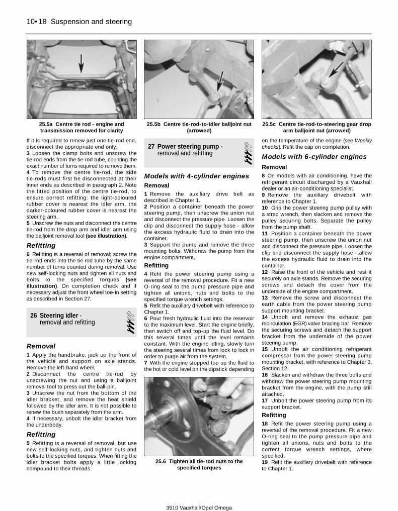
If it is required to renew just one tie-rod end,disconnect the appropriate end only.3 Loosen the clamp bolts and unscrew thetie-rod ends from the tie-rod tube, counting theexact number of turns required to remove them.4 To remove the centre tie-rod, the sidetie-rods must first be disconnected at theirinner ends as described in paragraph 2. Notethe fitted position of the centre tie-rod, toensure correct refitting: the light-colouredrubber cover is nearest the idler arm, thedarker-coloured rubber cover is nearest thesteering arm.5 Unscrew the nuts and disconnect the centretie-rod from the drop arm and idler arm usingthe balljoint removal tool (see illustration).
Refitting6 Refitting is a reversal of removal; screw thetie-rod ends into the tie rod tube by the samenumber of turns counted during removal. Usenew self-locking nuts and tighten all nuts andbolts to the specified torques (seeillustration). On completion check and ifnecessary adjust the front wheel toe-in settingas described in Section 27.
26 Steering idler -removal and refitting 3
Removal1 Apply the handbrake, jack up the front ofthe vehicle and support on axle stands.Remove the left-hand wheel.2 Disconnect the centre tie-rod byunscrewing the nut and using a balljointremoval tool to press out the ball-pin.3 Unscrew the nut from the bottom of theidler bracket, and remove the heat shieldfollowed by the idler arm. It is not possible torenew the bush separately from the arm.4 If necessary, unbolt the idler bracket fromthe underbody.
Refitting5 Refitting is a reversal of removal, but usenew self-locking nuts, and tighten nuts andbolts to the specified torques. When fitting theidler bracket bolts apply a little lockingcompound to their threads.
27 Power steering pump -removal and refitting 3
Models with 4-cylinder enginesRemoval1 Remove the auxiliary drive belt asdescribed in Chapter 1.2 Position a container beneath the powersteering pump, then unscrew the union nutand disconnect the pressure pipe. Loosen theclip and disconnect the supply hose - allowthe excess hydraulic fluid to drain into thecontainer.3 Support the pump and remove the threemounting bolts. Withdraw the pump from theengine compartment.
Refitting4 Refit the power steering pump using areversal of the removal procedure. Fit a newO-ring seal to the pump pressure pipe andtighten all unions, nuts and bolts to thespecified torque wrench settings.5 Refit the auxiliary drivebelt with reference toChapter 1.6 Pour fresh hydraulic fluid into the reservoirto the maximum level. Start the engine briefly,then switch off and top-up the fluid level. Dothis several times until the level remainsconstant. With the engine idling, slowly turnthe steering several times from lock to lock inorder to purge air from the system.7 With the engine stopped top up the fluid tothe hot or cold level on the dipstick depending
on the temperature of the engine (see Weeklychecks). Refit the cap on completion.
Models with 6-cylinder engines
Removal8 On models with air conditioning, have therefrigerant circuit discharged by a Vauxhalldealer or an air-conditioning specialist.9 Remove the auxiliary drivebelt withreference to Chapter 1.10 Grip the power steering pump pulley witha strap wrench, then slacken and remove thepulley securing bolts. Separate the pulleyfrom the pump shaft.11 Position a container beneath the powersteering pump, then unscrew the union nutand disconnect the pressure pipe. Loosen theclip and disconnect the supply hose - allowthe excess hydraulic fluid to drain into thecontainer.12 Raise the front of the vehicle and rest itsecurely on axle stands. Remove the securingscrews and detach the cover from theunderside of the engine compartment.13 Remove the screw and disconnect theearth cable from the power steering pumpsupport mounting bracket.14 Unbolt and remove the exhaust gasrecirculation (EGR) valve bracing bar. Removethe securing screws and detach the supportbracket from the underside of the powersteering pump.15 Unbolt the air conditioning refrigerantcompressor from the power steering pumpmounting bracket, with reference to Chapter 3,Section 12.16 Slacken and withdraw the three bolts andwithdraw the power steering pump mountingbracket from the engine, with the pump stillattached.17 Unbolt the power steering pump from itssupport bracket.
Refitting18 Refit the power steering pump using areversal of the removal procedure. Fit a newO-ring seal to the pump pressure pipe andtighten all unions, nuts and bolts to thecorrect torque wrench settings, wherespecified.19 Refit the auxiliary drivebelt with referenceto Chapter 1.
10•18 Suspension and steering
25.5a Centre tie rod - engine andtransmission removed for clarity
25.5b Centre tie-rod-to-idler balljoint nut(arrowed)
25.5c Centre tie-rod-to-steering gear droparm balljoint nut (arrowed)
25.6 Tighten all tie-rod nuts to thespecified torques
3510 Vauxhall/Opel Omega

20 Have the air conditioning systemrecharged by a Vauxhall dealer, or an airconditioning specialist.21 Pour fresh hydraulic fluid into the reservoirto the maximum level. Start the engine briefly,then switch off and top-up the fluid level. Dothis several times until the level remainsconstant. With the engine idling, slowly turnthe steering several times from lock to lock inorder to purge air from the system.22 With the engine stopped top up the fluid
to the hot or cold level on the dipstickdepending on the temperature of the engine(see Weekly checks). Refit the filler cap oncompletion.
28 Wheel alignment -checking and adjustment 5
1 Accurate wheel alignment is essential for
positive, accurate steering, stable roadholding and to prevent abnormal tyre wear.Wheel alignment checking is carried out withthe car loaded to its kerbside weight, and withthe tyre pressures correctly adjusted.2 The front toe setting, front camber angle,rear toe setting and rear camber angle are alladjustable, but can only be checked usingspecialised equipment; work of this natureshould therefore be entrusted to a Vauxhalldealer or suitably-equipped tyre specialist.
Suspension and steering 10•19
10
3510 Vauxhall/Opel Omega

3510 Vauxhall/Opel Omega
11•1
11
Chapter 11Bodywork and fittings
Torque wrench settings Nm lbf ftDriver’s airbag unit to steering wheel . . . . . . . . . . . . . . . . . . . . . . . . . . . 8 6Front seat to floorpan* . . . . . . . . . . . . . . . . . . . . . . . . . . . . . . . . . . . . . . 20 15Passenger airbag mounting bracket* . . . . . . . . . . . . . . . . . . . . . . . . . . . 20 15Passenger airbag unit to mounting bracket* . . . . . . . . . . . . . . . . . . . . . 8 6Seat belt anchor bolts . . . . . . . . . . . . . . . . . . . . . . . . . . . . . . . . . . . . . . 35 26Seat belt height adjustment bracket . . . . . . . . . . . . . . . . . . . . . . . . . . . . 20 15Seat belt inertia reel . . . . . . . . . . . . . . . . . . . . . . . . . . . . . . . . . . . . . . . . 35 26Steering wheel . . . . . . . . . . . . . . . . . . . . . . . . . . . . . . . . . . . . . . . . . . . . 20 15* Use a new nut/bolt/screw
Body exterior fittings - removal and refitting . . . . . . . . . . . . . . . . . . . 26Bonnet and support struts - removal, refitting and adjustment . . . . 8Bonnet lock spring - removal and refitting . . . . . . . . . . . . . . . . . . . . 10Bonnet release cable - removal and refitting . . . . . . . . . . . . . . . . . . . 9Bootlid - removal, refitting and adjustment . . . . . . . . . . . . . . . . . . . . 17Bootlid lock components - removal and refitting . . . . . . . . . . . . . . . 18Bumpers - removal and refitting . . . . . . . . . . . . . . . . . . . . . . . . . . . . 6Central locking system components - removal and refitting . . . . . . . 21Centre console - removal and refitting . . . . . . . . . . . . . . . . . . . . . . . 30Door - removal and refitting . . . . . . . . . . . . . . . . . . . . . . . . . . . . . . . . 11Door handles and lock components - removal and refitting . . . . . . . 13Door inner trim panel - removal and refitting . . . . . . . . . . . . . . . . . . . 12Door window regulator and glass - removal and refitting . . . . . . . . . 14Electric window components - removal and refitting . . . . . . . . . . . . 22Exterior mirrors and associated components - removal and refitting 23Facia assembly - removal and refitting . . . . . . . . . . . . . . . . . . . . . . . 32Fuel filler flap lock and release cable - removal and refitting . . . . . . 16
General information . . . . . . . . . . . . . . . . . . . . . . . . . . . . . . . . . . . . . . 1Glovebox - removal and refitting . . . . . . . . . . . . . . . . . . . . . . . . . . . . 31Interior trim - removal and refitting . . . . . . . . . . . . . . . . . . . . . . . . . . 29Lock and hinge lubrication . . . . . . . . . . . . . . . . . . . . . . . .see Chapter 1Maintenance - bodywork and underframe . . . . . . . . . . . . . . . . . . . . 2Maintenance - upholstery and carpets . . . . . . . . . . . . . . . . . . . . . . . 3Major body damage - repair . . . . . . . . . . . . . . . . . . . . . . . . . . . . . . . 5Minor body damage - repair . . . . . . . . . . . . . . . . . . . . . . . . . . . . . . . 4Radiator grille - removal and refitting . . . . . . . . . . . . . . . . . . . . . . . . 7Rear quarter window glass (estate models) - removal and refitting . 15Seat belt components - removal and refitting . . . . . . . . . . . . . . . . . . 28Seats - removal and refitting . . . . . . . . . . . . . . . . . . . . . . . . . . . . . . . 27Sunroof components - removal and refitting . . . . . . . . . . . . . . . . . . . 25Tailgate and support struts - removal, refitting and adjustment . . . . 19Tailgate lock components - removal and refitting . . . . . . . . . . . . . . . 20Windscreen and fixed window glass - general information . . . . . . . . 24
Specifications
Contents
Easy, suitable fornovice with littleexperience
Fairly easy, suitablefor beginner withsome experience
Fairly difficult,suitable for competentDIY mechanic
Difficult, suitable forexperienced DIYmechanic
Very difficult,suitable for expert DIYor professional
Degrees of difficulty
54321
1 General information
The bodyshell is of four-door Saloon, orfive-door Estate configuration, and is made ofhigh-strength low alloy sheet metal sections.The sections are alloy-galvanized on one orboth sides, depending on their position on thevehicle. Most components are weldedtogether, but some use is made of structuraladhesives. The front wings are bolted on.
The bonnet, doors and some othervulnerable panels are made of zinc-coatedmetal, and are further protected by beingcoated with an anti-chip primer prior to beingsprayed. The front and rear doors incorporatesafety bars as protection in the event of a sideimpact.
Electrically operated front windows arefitted to all models. Electrically operated rearwindows fitted as standard equipment on CD,CDX and Elite models and are optional onlower specification models.
Extensive use is made of plastic materials,mainly in the interior, but also in exteriorcomponents. The front and rear bumpers andthe front grille are injection-moulded from asynthetic material which is very strong, and yetlight. Plastic components such as wheel archliners are fitted to the underside of the vehicle,to improve the body’s resistance to corrosion.
2 Maintenance -bodywork and underframe 1
The general condition of a vehicle’sbodywork is the one thing that significantly
affects its value. Maintenance is easy, butneeds to be regular. Neglect, particularly afterminor damage, can lead quickly to furtherdeterioration and costly repair bills. It isimportant also to keep watch on those parts ofthe vehicle not immediately visible, for instancethe underside, inside all the wheel arches, andthe lower part of the engine compartment.
The basic maintenance routine for thebodywork is washing - preferably with a lot ofwater, from a hose. This will remove all theloose solids which may have stuck to thevehicle. It is important to flush these off insuch a way as to prevent grit from scratchingthe finish. The wheel arches and underframeneed washing in the same way, to remove anyaccumulated mud which will retain moistureand tend to encourage rust. Paradoxicallyenough, the best time to clean the underframeand wheel arches is in wet weather, when themud is thoroughly wet and soft. In very wet

weather, the underframe is usually cleaned oflarge accumulations automatically, and this isa good time for inspection.
Periodically, except on vehicles with a wax-based underbody protective coating, it is agood idea to have the whole of the underframeof the vehicle steam-cleaned, enginecompartment included, so that a thoroughinspection can be carried out to see whatminor repairs and renovations are necessary.Steam-cleaning is available at many garages,and is necessary for the removal of theaccumulation of oily grime, which sometimesis allowed to become thick in certain areas. Ifsteam-cleaning facilities are not available,there are one or two excellent grease solventsavailable, which can be brush-applied; the dirtcan then be simply hosed off. Note that thesemethods should not be used on vehicles withwax-based underbody protective coating, orthe coating will be removed. Such vehiclesshould be inspected annually, preferably justprior to Winter, when the underbody should bewashed down, and any damage to the waxcoating repaired. Ideally, a completely freshcoat should be applied. It would also be worthconsidering the use of such wax-basedprotection for injection into door panels, sills,box sections, etc, as an additional safeguardagainst rust damage, where such protection isnot provided by the vehicle manufacturer.
After washing paintwork, wipe off with achamois leather to give an unspotted clearfinish. A coat of clear protective wax polish willgive added protection against chemicalpollutants in the air. If the paintwork sheen hasdulled or oxidised, use a cleaner/polishercombination to restore the brilliance of theshine. This requires a little effort, but suchdulling is usually caused because regularwashing has been neglected. Care needs to betaken with metallic paintwork, as special non-abrasive cleaner/polisher is required to avoiddamage to the finish. Always check that thedoor and ventilator opening drain holes andpipes are completely clear, so that water canbe drained out. Brightwork should be treated inthe same way as paintwork. Windscreens andwindows can be kept clear of the smeary filmwhich often appears, by the use of proprietaryglass cleaner. Never use any form of wax orother body or chromium polish on glass.
3 Maintenance -upholstery and carpets 1
Mats and carpets should be brushed orvacuum-cleaned regularly, to keep them free ofgrit. If they are badly stained, remove themfrom the vehicle for scrubbing or sponging, andmake quite sure they are dry before refitting.Seats and interior trim panels can be keptclean by wiping with a damp cloth. If they dobecome stained (which can be more apparenton light-coloured upholstery), use a little liquiddetergent and a soft nail brush to scour the
grime out of the grain of the material. Do notforget to keep the headlining clean in the sameway as the upholstery. When using liquidcleaners inside the vehicle, do not over-wet thesurfaces being cleaned. Excessive damp couldget into the seams and padded interior,causing stains, offensive odours or even rot. Ifthe inside of the vehicle gets wet accidentally, itis worthwhile taking some trouble to dry it outproperly, particularly where carpets areinvolved. Do not leave oil or electric heatersinside the vehicle for this purpose.
4 Minor body damage -repair 2
Repairs of minor scratches inbodywork
If the scratch is very superficial, and doesnot penetrate to the metal of the bodywork,repair is very simple. Lightly rub the area ofthe scratch with a paintwork renovator, or avery fine cutting paste, to remove loose paintfrom the scratch, and to clear the surroundingbodywork of wax polish. Rinse the area withclean water.
Apply touch-up paint to the scratch using afine paint brush; continue to apply fine layersof paint until the surface of the paint in thescratch is level with the surroundingpaintwork. Allow the new paint at least twoweeks to harden, then blend it into thesurrounding paintwork by rubbing the scratcharea with a paintwork renovator or a very finecutting paste. Finally, apply wax polish.
Where the scratch has penetrated rightthrough to the metal of the bodywork, causingthe metal to rust, a different repair techniqueis required. Remove any loose rust from thebottom of the scratch with a penknife, thenapply rust-inhibiting paint, to prevent theformation of rust in the future. Using a rubberor nylon applicator, fill the scratch withbodystopper paste. If required, this paste canbe mixed with cellulose thinners, to provide avery thin paste which is ideal for filling narrowscratches. Before the stopper-paste in thescratch hardens, wrap a piece of smoothcotton rag around the top of a finger. Dip thefinger in cellulose thinners, and quickly sweepit across the surface of the stopper-paste inthe scratch; this will ensure that the surface ofthe stopper-paste is slightly hollowed. Thescratch can now be painted over as describedearlier in this Section.
Repairs of dents in bodyworkWhen deep denting of the vehicle’s
bodywork has taken place, the first task is topull the dent out, until the affected bodyworkalmost attains its original shape. There is littlepoint in trying to restore the original shapecompletely, as the metal in the damaged areawill have stretched on impact, and cannot bereshaped fully to its original contour. It is better
to bring the level of the dent up to a point whichis about 3 mm below the level of thesurrounding bodywork. In cases where thedent is very shallow anyway, it is not worthtrying to pull it out at all. If the underside of thedent is accessible, it can be hammered outgently from behind, using a mallet with awooden or plastic head. Whilst doing this, holda suitable block of wood firmly against theoutside of the panel, to absorb the impact fromthe hammer blows and thus prevent a largearea of the bodywork from being ‘belled-out’.
Should the dent be in a section of thebodywork which has a double skin, or someother factor making it inaccessible frombehind, a different technique is called for. Drillseveral small holes through the metal insidethe area - particularly in the deeper section.Then screw long self-tapping screws into theholes, just sufficiently for them to gain a goodpurchase in the metal. Now the dent can bepulled out by pulling on the protruding headsof the screws with a pair of pliers.
The next stage of the repair is the removal ofthe paint from the damaged area, and from aninch or so of the surrounding ‘sound’bodywork. This is accomplished most easily byusing a wire brush or abrasive pad on a powerdrill, although it can be done just as effectivelyby hand, using sheets of abrasive paper. Tocomplete the preparation for filling, score thesurface of the bare metal with a screwdriver orthe tang of a file, or alternatively, drill smallholes in the affected area. This will provide areally good ‘key’ for the filler paste.
To complete the repair, see the Section onfilling and respraying.
Repairs of rust holes or gashes in bodywork
Remove all paint from the affected area,and from an inch or so of the surrounding‘sound’ bodywork, using an abrasive pad or awire brush on a power drill. If these are notavailable, a few sheets of abrasive paper willdo the job most effectively. With the paintremoved, you will be able to judge the severityof the corrosion, and therefore decidewhether to renew the whole panel (if this ispossible) or to repair the affected area. Newbody panels are not as expensive as mostpeople think, and it is often quicker and moresatisfactory to fit a new panel than to attemptto repair large areas of corrosion.
Remove all fittings from the affected area,except those which will act as a guide to theoriginal shape of the damaged bodywork (egheadlamp shells etc). Then, using tin snips or ahacksaw blade, remove all loose metal and anyother metal badly affected by corrosion.Hammer the edges of the hole inwards, in orderto create a slight depression for the filler paste.
Wire-brush the affected area to remove thepowdery rust from the.surface of the remaining metal. Paint theaffected area with rust-inhibiting paint; if theback of the rusted area is accessible, treatthis also.
11•2 Bodywork and fittings
3510 Vauxhall/Opel Omega

Before filling can take place, it will benecessary to block the hole in some way. Thiscan be achieved by the use of aluminium orplastic mesh, or aluminium tape.
Aluminium or plastic mesh, or glass-fibrematting is probably the best material to use fora large hole. Cut a piece to the approximatesize and shape of the hole to be filled, thenposition it in the hole so that its edges arebelow the level of the surrounding bodywork. Itcan be retained in position by several blobs offiller paste around its periphery.
Aluminium tape should be used for small orvery narrow holes. Pull a piece off the roll, trimit to the approximate size and shape required,then pull off the backing paper (if used) andstick the tape over the hole; it can beoverlapped if the thickness of one piece isinsufficient. Burnish down the edges of thetape with the handle of a screwdriver orsimilar, to ensure that the tape is securelyattached to the metal underneath.
Bodywork repairs - filling and respraying
Before using this Section, see the Sectionson dent, deep scratch, rust holes and gashrepairs.
Many types of bodyfiller are available, butgenerally speaking, those proprietary kitswhich contain a tin of filler paste and a tube ofresin hardener are best for this type of repair. Awide, flexible plastic or nylon applicator will befound invaluable for imparting a smooth andwell-contoured finish to the surface of the filler.
Mix up a little filler on a clean piece of card orboard - measure the hardener carefully (followthe maker’s instructions on the pack),otherwise the filler will set too rapidly or tooslowly. Using the applicator, apply the fillerpaste to the prepared area; draw the applicatoracross the surface of the filler to achieve thecorrect contour and to level the surface. Assoon as a contour that approximates to thecorrect one is achieved, stop working the paste- if you carry on too long, the paste will becomesticky and begin to ‘pick-up’ on the applicator.Continue to add thin layers of filler paste at 20-minute intervals, until the level of the filler is justproud of the surrounding bodywork.
Once the filler has hardened, the excesscan be removed using a metal plane or file.From then on, progressively-finer grades ofabrasive paper should be used, starting with a40-grade production paper, and finishing witha 400-grade wet-and-dry paper. Always wrapthe abrasive paper around a flat rubber, cork,or wooden block - otherwise the surface ofthe filler will not be completely flat. During thesmoothing of the filler surface, the wet-and-dry paper should be periodically rinsed inwater. This will ensure that a very smoothfinish is imparted to the filler at the final stage.
At this stage, the ‘dent’ should besurrounded by a ring of bare metal, which inturn should be encircled by the finely‘feathered’ edge of the good paintwork. Rinsethe repair area with clean water, until all of the
dust produced by the rubbing-downoperation has gone.
Spray the whole area with a light coat of -this will show up any imperfections in thesurface of the filler. Repair these imperfectionswith fresh filler paste or bodystopper, andonce more smooth the surface with abrasivepaper. If bodystopper is used, it can be mixedwith cellulose thinners, to form a really thinpaste which is ideal for filling small holes.Repeat this spray-and-repair procedure untilyou are satisfied that the surface of the filler,and the feathered edge of the paintwork, areperfect. Clean the repair area with clean water,and allow to dry fully.
The repair area is now ready for finalspraying. Paint spraying must be carried outin a warm, dry, windless and dust-freeatmosphere. This condition can be createdartificially if you have access to a large indoorworking area, but if you are forced to work inthe open, you will have to pick your day verycarefully. If you are working indoors, dousingthe floor in the work area with water will helpto settle the dust which would otherwise be inthe atmosphere. If the repair area is confinedto one body panel, mask off the surroundingpanels; this will help to minimise the effects ofa slight mis-match in paint colours. Bodyworkfittings (eg chrome strips, door handles etc)will also need to be masked off. Use genuinemasking tape, and several thicknesses ofnewspaper, for the masking operations.
Before commencing to spray, agitate theaerosol can thoroughly, then spray a test area(an old tin, or similar) until the technique ismastered. Cover the repair area with a thick coatof primer; the thickness should be built up usingseveral thin layers of paint, rather than one thickone. Using 400 grade wet-and-dry paper, rubdown the surface of the primer until it is reallysmooth. While doing this, the work area shouldbe thoroughly doused with water, and the wet-and-dry paper periodically rinsed in water. Allowto dry before spraying on more paint.
Spray on the top coat, again building up thethickness by using several thin layers of paint.Start spraying in the centre of the repair area,and then, using a circular motion, workoutwards until the whole repair area andabout 2 inches of the surrounding originalpaintwork is covered. Remove all maskingmaterial 10 to 15 minutes after spraying onthe final coat of paint.
Allow the new paint at least two weeks toharden, then, using a paintwork renovator or avery fine cutting paste, blend the edges of thepaint into the existing paintwork. Finally, applywax polish.
Plastic componentsWith the use of more and more plastic body
components by the vehicle manufacturers (egbumpers. spoilers, and in some cases majorbody panels), rectification of more seriousdamage to such items has become a matter ofeither entrusting repair work to a specialist in thisfield, or renewing complete components. Repair
of such damage by the DIY owner is not reallyfeasible, owing to the cost of the equipment andmaterials required for effecting such repairs. Thebasic technique involves making a groove alongthe line of the crack in the plastic, using a rotaryburr in a power drill. The damaged part is thenwelded back together, using a hot air gun toheat up and fuse a plastic filler rod into thegroove. Any excess plastic is then removed, andthe area rubbed down to a smooth finish. It isimportant that a filler rod of the correct plastic isused, as body components can be made of avariety of different types (eg polycarbonate,ABS, polypropylene).
Damage of a less serious nature (abrasions,minor cracks etc) can be repaired by the DIYowner using a two-part epoxy filler repair.Once mixed in equal, this is used in similarfashion to the bodywork filler used on metalpanels. The filler is usually cured in twenty tothirty minutes, ready for sanding and painting.
If the owner is renewing a completecomponent himself, or if he has repaired itwith epoxy filler, he will be left with theproblem of finding a suitable paint for finishingwhich is compatible with the type of plasticused. At one time, the use of a universal paintwas not possible, owing to the complex rangeof plastics encountered in body componentapplications. Standard paints, generallyspeaking, will not bond to plastic or rubbersatisfactorily, but suitable paints to match anyplastic or rubber finish, can be obtained fromdealers. However, it is now possible to obtaina plastic body parts finishing kit whichconsists of a pre-primer treatment, a primerand coloured top coat. Full instructions arenormally supplied with a kit, but basically, themethod of use is to first apply the pre-primerto the component concerned, and allow it todry for up to 30 minutes. Then the primer isapplied, and left to dry for about an hourbefore finally applying the special-colouredtop coat. The result is a correctly-colouredcomponent, where the paint will flex with theplastic or rubber, a property that standardpaint does not normally possess.
5 Major body damage -repair 5
Where serious damage has occurred, orlarge areas need renewal due to neglect, itmeans that complete new panels will needwelding-in, and this is best left to professionals.If the damage is due to impact, it will also benecessary to check completely the alignmentof the bodyshell, and this can only be carriedout accurately by a Vauxhall/Opel dealer usingspecial jigs. If the body is left misaligned, it isprimarily dangerous, as the car will not handleproperly, and secondly, uneven stresses will beimposed on the steering, suspension andpossibly transmission, causing abnormal wear,or complete failure, particularly to such itemsas the tyres.
Bodywork and fittings 11•3
11
3510 Vauxhall/Opel Omega

6 Bumpers - removal and refitting 2
Front bumper
Removal1 Remove the radiator grille as described inSection 7. Remove the securing screws anddetach the trim panels from the lower edge ofeach headlamp unit (see illustrations).2 Remove the screws securing the loweredge of the front wheel arch liner in position,then unscrew and remove the two mountingscrews from the trailing edge of the bumpermoulding (see illustrations).3 Remove the plastic rivets securing thelower edge of the front bumper to the frontvalance. To do this, depress the centre pinsusing a screwdriver, then prise out the rivetbody (see illustrations).4 Unscrew and remove the upper mountingbolts, located next to the headlamp units,then carefully withdraw the front bumper fromthe front of the vehicle (see illustrations). Asthe wiring becomes accessible, unplug thewiring from the foglamps and ambient airtemperature sensor (where applicable).5 If required, slacken and withdraw thesecuring bolts and then withdraw the bumpercentre member from the front of the vehicle(see illustrations).
11•4 Bodywork and fittings
6.1a Remove the securing screws . . . 6.1b . . . and detach the trim panels fromthe lower edge of each headlamp unit
6.2b . . . and lower mounting screws fromthe trailing edge of the bumper moulding
6.4b . . . then carefully withdraw the frontbumper from the front of the vehicle
6.5a Slacken and withdraw the securingbolts . . .
6.5b . . . and then withdraw the bumpercentre member from the front of the
vehicle
6.3a Depress the centre pins using ascrewdriver . . .
6.2a Unscrew and remove the upper . . .
6.3b . . . then remove the plastic rivetssecuring the lower edge of the front
bumper to the front valance
6.4a Unscrew and remove the uppermounting bolts . . .
3510 Vauxhall/Opel Omega

Refitting6 Refitting is a reversal of removal, noting thefollowing points.a) Tighten all fixings to the correct torque,
where specified.b) When refitting the headlamp trim panels,
ensure that the locating lugs engagewhich their corresponding recesses.
c) Ensure that the ambient temperaturesensor wiring is securely reconnected,where applicable.
Rear bumper - Saloon models
Removal7 At the rear of each wheel arch, unscrew the
bolts (three each side) securing the upper andlower leading edge of the bumper moulding tothe bodywork (see illustration).8 Open the bootlid, then remove the screwsand withdraw the boot striker trim panel (seeillustration).9 Remove the plastic rivets securing thelower edge of the bumper to the rear valance.To do this, depress the centre pins using ascrewdriver, then prise out the rivet body (seeillustrations).10 Prise off the protective caps, thenunscrew the four screws securing the upperedge of the bumper moulding to thebodywork (see illustration).11 Carefully withdraw the rear bumper fromthe rear of the vehicle, disconnecting the
number plate lamp unit wiring as it becomesaccessible (see illustration).12 To remove the rear bumper centremember, slacken and withdraw the securingnuts, then detach the centre member from itsmounting bracket (see illustrations).
Refitting13 Refitting is a reversal of removal but tightenall fixings to the correct torque, where specified.
Rear bumper - Estate models
Removal14 Remove the securing screws and detachthe lower edges of the plastic liners from bothrear wheel arches (see illustration).
Bodywork and fittings 11•5
11
6.7 Unscrew the bolts securing the upperand lower leading edge of the bumper
moulding to the bodywork
6.8 Remove the screws and withdraw theboot striker trim panel
6.9a Depress the centre pins using ascrewdriver . . .
6.12a Slacken and withdraw the securingnuts . . .
6.12b . . . then detach the centre memberfrom its mounting bracket
6.14 Remove the securing screws anddetach the lower edges of the plastic liners
from both rear wheel arches
6.9b . . . then prise out the plastic rivetssecuring the lower edge of the bumper to
the rear valance
6.10 Prise off the protective caps andremove the screws securing the upper
edge of the bumper moulding to thebodywork
6.11 Carefully withdraw the rear bumperfrom the vehicle
3510 Vauxhall/Opel Omega
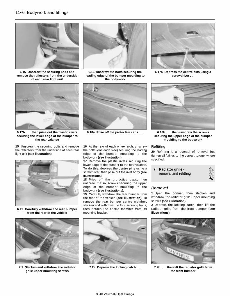
15 Unscrew the securing bolts and removethe reflectors from the underside of each rearlight unit (see illustration).
16 At the rear of each wheel arch, unscrewthe bolts (one each side) securing the leadingedge of the bumper moulding to thebodywork (see illustration).17 Remove the plastic rivets securing thelower edge of the bumper to the rear valance.To do this, depress the centre pins using ascrewdriver, then prise out the rivet body (seeillustrations).18 Prise off the protective caps, thenunscrew the six screws securing the upperedge of the bumper moulding to thebodywork (see illustrations).19 Carefully withdraw the rear bumper fromthe rear of the vehicle (see illustration). Toremove the rear bumper centre member,slacken and withdraw the four securing bolts,then detach the centre member from itsmounting bracket.
Refitting20 Refitting is a reversal of removal buttighten all fixings to the correct torque, wherespecified.
7 Radiator grille -removal and refitting 1
Removal1 Open the bonnet, then slacken andwithdraw the radiator grille upper mountingscrews (see illustration).2 Depress the locking catch, then lift theradiator grille from the front bumper (seeillustrations).
11•6 Bodywork and fittings
6.15 Unscrew the securing bolts andremove the reflectors from the underside
of each rear light unit
6.16 unscrew the bolts securing theleading edge of the bumper moulding to
the bodywork
6.17a Depress the centre pins using ascrewdriver . . .
6.17b . . . then prise out the plastic rivetssecuring the lower edge of the bumper to
the rear valance
6.18b . . . then unscrew the screwssecuring the upper edge of the bumper
moulding to the bodywork
6.18a Prise off the protective caps . . .
7.1 Slacken and withdraw the radiatorgrille upper mounting screws
6.19 Carefully withdraw the rear bumperfrom the rear of the vehicle
7.2a Depress the locking catch . . . 7.2b . . . then lift the radiator grille fromthe front bumper
3510 Vauxhall/Opel Omega

Refitting3 Refitting is a reversal of removal, ensuringthat the lugs on the lower edge of the grilleengage correctly with the correspondingrecesses in the upper edge of the bumper.
8 Bonnet and support struts -removal, refitting andadjustment
2Bonnet
Removal1 Open the bonnet, and have an assistantsupport it. Disconnect the support struts fromthe bonnet balljoints, as described in the nextsub-Section.2 Using a marker pen or paint, mark aroundthe hinge positions on the bonnet.3 Disconnect the windscreen washer fluidhose at the connector and support. Unplugthe wiring harness at the connector.4 With the aid of the assistant, unscrew thebolts securing the bonnet to the hinges onboth sides.5 Lift off the bonnet taking care not todamage the vehicle paintwork.
Refitting6 With the aid of the assistant, align themarks made on the bonnet before removalwith the hinges, then refit and tighten thebonnet securing bolts.7 Reconnect the windscreen washer fluidhose and wiring harness.8 Refit the support struts to the bonnet asdescribed in the next sub-Section, then checkthe bonnet adjustment as follows.
Adjustment9 Lower the bonnet slowly to its closedposition, ensuring that misalignment does notcause the edges of the bonnet to strike thewings. Check that there is an equal gapbetween the sides of the bonnet and the wingpanels, and between the front of the bonnetand the upper edges of the headlamp units.Check also that the bonnet sits flush inrelation to the surrounding body panels.10 The bonnet should close smoothly andpositively without excessive pressure. If this isnot the case, adjustment will be required.11 To adjust the bonnet alignment, loosenthe bonnet mounting bolts, and move thebonnet on the bolts as required (the bolt holesin the hinges are elongated to allowadjustment). To adjust the bonnet front heightin relation to the front wings, adjustablerubber bump stops are fitted to the frontcorners of the bonnet. These may be screwedin or out as necessary. After making anadjustment, the bonnet striker must beadjusted so that the lock spring holds thebonnet firmly against the rubber bump stops.Loosen the locknut and screw the striker in orout as necessary.
Support struts
Removal12 Open the bonnet, and have an assistantsupport it.13 Using a screwdriver prise out the retainingspring clips and disconnect the upper end ofthe strut from the balljoints on the bonnet.14 Unscrew the securing bolts and detachthe lower end of the strut from the bodywork.Note which way round the strut is fitted.
Refitting15 Refitting is a reversal of removal.
9 Bonnet release cable -removal and refitting 3
Removal1 Remove the lower trim panel from under thedriver’s side of the facia. Undo the screws andremove the plastic panel to the right of thedrivers footwell, to expose the release cablehandle mountings.2 Open the bonnet and remove the radiatorgrille as described in Section 7. Release thesecuring clips, undo the screws and removethe cover panel from above the radiator.3 Disconnect the front end of the releasecable from the bonnet lock spring, byreaching between the radiator and thebodywork. On models with air conditioning, itwill be necessary to remove the left handauxiliary cooling fan (see Chapter 3) from thecondenser to allow access to the underside ofthe bonnet lock.4 Unbolt the release lever and its mountingbracket from the bodywork at the right of thedriver’s footwell. Note that the release handleand cable are only available as a completeassembly.5 Release the cable from the support clips inthe engine compartment, then withdraw thecable through the rubber grommet andwithdraw into the engine compartment. Notethat the cable runs from the bonnet lockaround the left hand side of the enginecompartment behind the main fusebox, thenalong the bulkhead to the right hand side ofthe engine compartment before passingthrough the bulkhead and entering thepassenger compartment. As an aid torefitting, tie a length of string to the cablebefore removing it and leave the string inposition ready for refitting.
Refitting6 Refitting is a reversal of removal, but tie thestring to the release lever end of the cable,and use the string to pull the cable intoposition. Ensure that the cable is routed asnoted before removal, and make sure that thegrommet is correctly seated.
10 Bonnet lock spring -removal and refitting 2
Removal1 The bonnet is held in its locked position bymeans of a strong coil spring and a pin, whichengages with the striker plate on the frontedge of the bonnet. The release cable isconnected to the striker plate catch, which isheld in the locked position by a spring.2 The pin and its coil spring may be removedfrom the bonnet by unscrewing it from thelocknut, however measure its fitted length firstas a guide to refitting it.3 To remove the striker plate spring, firstremove the radiator grille (see Section 7) thendisconnect the bonnet release cable andunhook the spring from the frontcrossmember.
Refitting4 Refitting is a reversal of removal.
11 Door -removal and refitting 3
Front door
Removal1 The door hinges are welded onto the doorframe and the body pillar. Where necessary,adjustment is carried out using special toolsto bend the hinges.2 Open the door to gain access to the wiringconnector, which is fixed to the front insideedge of the door. Disconnect the wiringconnector from the front edge of the door. Todo this, unscrew the connector locking ring,then pull the connector away from the door(see illustration).3 Unscrew and remove the bolt securing thedoor check link to the vehicle body (seeillustration).
Bodywork and fittings 11•7
11
11.2 Location of the front door wiringconnector (arrowed)
3510 Vauxhall/Opel Omega

4 Remove the plastic covers from the doorhinge pins (see illustration). Have anassistant support the door, then drive bothhinge pins out of position using a hammer andsuitable punch. Note: Vauxhall/Opeltechnicians use a special hinge pin removaltool which acts like a slide hammer. Removethe door from the vehicle.5 Inspect the hinge pins for signs of wear ordamage, and renew if necessary.
Refitting6 Refitting is a reversal of removal, but checkthat when shut the door is positioned centrallywithin the body aperture. If the hinge pinshave been renewed and adjustment is stillrequired, the hinges will have to be re-alignedusing special tools. This work must be carriedout by a Vauxhall/Opel dealer, however minoradjustment may be possible by physically
lifting the door on its hinges. After adjustment,make sure that the door lock engagescorrectly with the striker on the body pillar. Ifnecessary loosen the striker retaining screwsusing a Torx key, then reposition the strikerand tighten the screws.
Rear door7 The removal and refitting procedure is thesame as that described for the front door,except that the wiring harness is locatedbehind a rubber grommet at the base of theB-pillar. To gain access to it, open the frontand rear door, prise the grommet from thebodywork and withdraw the connector fromthe B-pillar.
12 Door inner trim panel -removal and refitting 2
Front door
Removal1 Disconnect the battery negative (earth) lead(see Chapter 5A).2 On models with manually-adjustable doormirrors, carefully pull off the mirror adjustmenthandle, then prise off the triangular plasticcover taking care not to damage the retainingclips. Remove the foam padding. On modelswith electrically adjustable door mirrors,carefully prise off the triangular plastic coverpanel, remove the foam padding and unplugthe wiring from the tweeter unit (see Section 23
for details).3 Prise the plastic cover from the inside of theinterior door handle (see illustration).4 Carefully prise the grip from the undersideof the door pull handle (see illustration).5 Prise off the small plastic covers to exposethe heads of the door handle surroundsecuring screws. Undo the screws andremove the door pull handle. (seeillustrations).6 On base models, remove the windowregulator handle by first closing the windowand noting the fitted angle of the handle.Using a piece of cloth rag inserted behind thehandle, release the clip then withdraw thehandle from the splined shaft.7 Prise the clip from the door locking knob,then detach the knob from the locking rod.Undo the screw and remove the locking knobtrim panel (see illustrations).
11•8 Bodywork and fittings
11.3 Unscrew and remove the bolt(arrowed) securing the door check link to
the vehicle body
11.4 Remove the plastic covers from thedoor hinge pins
12.3 Prise the plastic cover from the insideof the interior door handle
12.4 Carefully prise the grip from theunderside of the door pull handle
12.5a Prise off the small plastic covers . . .
12.5b . . . undo the screws . . . 12.5c . . . and remove the door pull handle12.7a Prise the clip from the door lockingknob and then detach the knob from the
locking rod
3510 Vauxhall/Opel Omega

8 Prise off the protective caps (whereapplicable) then unscrew and remove thescrews from the lower and front edges of thetrim panel (see illustrations).9 Use a wide-bladed screwdriver or trimremoval tool to carefully prise the panel clipsfrom the door. Unhook the top of the paneland remove it from the door (see illustration).10 If necessary, carefully peel the protectiveplastic membrane from the door (seeillustration). Note that it will necessary to cutaround some of the panel securing clips torelease the membrane from the door.
Warning: On later models wherethe Supplementary RestraintSystem (SRS) includes side
airbags, the door side impact sensors are airpressure sensitive and will only operatecorrectly if the protective plastic doormembrane is refitted correctly; bear this inmind when removing the membrane from
the door. See Chapter 12 for more infor-mation on the Supplementary RestraintSystem.
Refitting11 Refitting is a reversal of removal. Onmodels fitted with side airbags, ensure thatthe plastic door membrane is securely refitted(see illustration). The sealing strip around theedge of the membrane must adhere to thedoor without gaps, to form an airtight seal. Ifthe membrane was cut or torn during itsremoval, ensure that the loose edges arestuck to the door using a suitableadhesive/sealant. If you are in doubt about theintegrity of the seal, it’s best to renew themembrane and sealing strip entirely.
Rear door
Removal12 Disconnect the battery negative (earth)
lead (see Chapter 5A).13 Use a small screwdriver to carefully priseoff the ashtray unit from the armrest (seeillustration).14 Unclip the trim panel from behind the doorlock release handle (see illustration).15 Carefully prise the grip from the undersideoff the door pull handle (see illustration).16 Prise the clip from the door locking knob,then detach the knob from the locking rod.Undo the screw and remove the locking knobtrim panel (see illustrations).17 Unscrew and remove the door pull handleretaining screws and then remove the pullhandle from the door. Where applicable,unplug the window switch wiring connector asit becomes accessible (see illustrations). Onmodels with rear door window demister fans,it will be necessary to lift the door pull handleassembly upwards, to detach it from the airducting.
Bodywork and fittings 11•9
11
12.7b Undo the screw . . . 12.7c . . . and remove the locking knobtrim panel
12.8a Prise off the protective caps . . .
12.8b . . . then remove the screws fromthe lower and front edges of the trim panel
12.9 Remove the trim panel from the door 12.10 If necessary, carefully peel theprotective plastic membrane from the door
12.11 On models fitted with side airbags, itis important that the sealing strip aroundthe edge of the membrane adheres to thedoor without gaps, to form an airtight seal
12.13 Use a small screwdriver to carefullyprise off the ashtray unit from the armrest
12.14 Unclip the trim panel from behind thedoor lock release handle
3510 Vauxhall/Opel Omega

18 Where a manual window regulator isfitted, fully close the window and note theposition of the regulator handle. The handlemust now be removed from the splined shaft.To do this, locate a cloth rag between the
handle and the trim panel and pull it to oneside to release the spring clip. The handle cannow be removed from the splined shaft andthe escutcheon removed.19 Prise the kerb lamp unit from the door trim
panel and disconnect the wiring from it (seeChapter 12, Section 6).20 Unscrew and remove the screws from therear and lower edges of the trim panel, thenuse a wide-bladed screwdriver or removal tool
11•10 Bodywork and fittings
12.15 Carefully prise the grip from theunderside of the door pull handle
12.16a Prise the clip from the door lockingknob . .
12.16b . . . then detach the knob from thelocking rod
12.20b . . . lift the panel upwards todisengage it from the door, then remove it
from the vehicle12.20c Unplug the speaker wiring as it
becomes accessible12.21 If necessary, carefully peel the
protective plastic membrane from the door
12.17b . . . and then remove the pullhandle from the door
12.17c Where applicable, unplug thewindow switch wiring connector
12.20a Unscrew and remove the screwsfrom the rear and lower edges of the trim
panel . . .
12.16c Undo the screw . . . 12.16d . . . and remove the locking knobtrim panel
12.17a Unscrew and remove the door pullhandle retaining screws . . .
3510 Vauxhall/Opel Omega

to carefully prise the inner trim panel clipsfrom the inside of the rear door. Lift the panelupwards to disengage it from the door, thenunplug the speaker wiring as it becomesaccessible. Remove the trim panel from thevehicle (see illustrations).21 If necessary, carefully peel the protectiveplastic membrane from the door (seeillustration). Note that it will necessary to cutaround some of the panel securing clips torelease the membrane from the door.
Refitting22 Refitting is a reversal of removal.
13 Door handles and lock components -removal and refitting 3
Door interior handle
Removal1 Remove the door inner trim panel and peelback the protective plastic membrane asdescribed in Section 12.2 Press the interior handle forwards torelease it from the elongated slots in the doorpanel (see illustration).3 Twist the handle anticlockwise to unhook itfrom the link rod (see illustration).
Refitting4 Refitting is a reversal of removal.
Front door exterior handle
Removal5 Remove the door inner trim panel, and peelback the protective plastic membrane asdescribed in Section 12.6 On models fitted with side air bags, removethe door side impact sensor together with itsmounting bracket; refer to Section 24 ofChapter 12.7 Unscrew the nuts from the rear of theexterior handle using a socket insertedthrough the aperture provided (seeillustration).8 Carefully withdraw the exterior handle fromthe door taking care not to damage thepaintwork. Unplug the wiring connector,where applicable - cable tie the wire to thehandle aperture, to prevent it dropping downinside the door.
9 Release the plastic clip, detach the doorlock mechanism link rod and withdraw thehandle from the door through handle aperture(see illustrations).
Refitting10 Refitting is a reversal of removal, butbefore refitting the inner trim panel, screwdown the knurled nut on the handle linkageuntil it is free of play.
Rear door exterior handle
Removal11 Remove the door inner trim panel, andpeel back the protective plastic membrane asdescribed in Section 12.12 Undo the securing screw and remove theplastic security panel from the door lockmechanism (see illustrations).
Bodywork and fittings 11•11
11
13.2 Press the interior handle forwards torelease it from the elongated slots in the
door panel
13.3 Twist the handle anticlockwise tounhook it from the link rod
13.7 Unscrew the nuts (arrowed) from therear of the exterior handle
13.9c . . . and withdraw the handle fromthe door through handle aperture
13.12a Undo the securing screw . . . 13.12b . . . and remove the plastic securitypanel from the door lock mechanism
13.9a Release the plastic clip . . . 13.9b . . . detach the door lock mechanismlink rod . . .
3510 Vauxhall/Opel Omega

13 Unscrew the nuts, using a socket insertedthrough the aperture provided, and removethe mounting plate from the rear of theexterior door handle (see illustrations).14 Disconnect the handle link rod from thedoor lock by prising open the plastic clips(see illustration).15 Withdraw the handle from the door takingcare not to damage the paintwork (seeillustration).
Refitting16 Refitting is a reversal of removal, butbefore refitting the inner trim panel, screwdown the knurled nut on the handle link roduntil it is free of play.
Front door lock cylinder -models with conventional lockcylinder
Removal17 Remove the exterior handle as describedpreviously in this Section.18 Insert the key in the lock cylinder and turnit to the right.19 Prise off the circlip and remove thecylinder from the rear of the handle assembly.
Refitting20 Refitting is a reversal of removal.
Front door lock cylinder -models with freewheeling lockcylinder
Removal21 Remove the exterior handle assembly asdescribed previously in this Section.
22 Note the orientation of the cylinderhousing, then drive out the roll pin using asuitable punch, and rotate the cylinderhousing to release it from the exterior handleassembly.23 Withdraw the lock cylinder from thehandle assembly.
Refitting24 Refitting is a reversal of removal. Aftersecuring the cylinder housing in position witha new roll pin, turn the handle assembly over
and splay out the end roll pin using the punch,to ensure that the pin cannot fall out (seeillustration).
Front door lock
Removal25 Remove the door inner trim panel, andpeel back the protective plastic membrane asdescribed in Section 12.26 On models fitted with side air bags,remove the door side impact sensor together
11•12 Bodywork and fittings
13.13a Unscrew the nuts, using a socketinserted through the aperture provided . . .
13.13b . . . and remove the mounting platefrom the rear of the exterior door handle
13.14 Disconnect the link rod from thedoor handle by prising open the plastic clip
13.15 Withdraw the handle from the door
3510 Vauxhall/Opel Omega
13.24 Exploded view of front door lock cylinder assembly - models with free-wheeling locks
1 Roll pin2 Housing3 Lock cylinder
4 Channel sleeve5 Ball6 Clutch
7 Bracket8 Washer9 Carrier and lever
10 Torsion spring11 Pressure spring

with its mounting bracket; refer to Section 24of Chapter 12.27 Remove the exterior door handle asdescribed previously in this Section.28 Where fitted, disconnect the centrallocking wiring from the lock by levering up theplastic retainer and separating the connector.29 Disconnect the link rods arms for theouter door handle, lock cylinder (whereapplicable) and inner door handle from thelock (see illustration).30 At the rear edge of the door, undo thethree retaining screws then withdraw the lockfrom inside the door while guiding the lockingknob link rod through the hole provided (seeillustration).
Refitting31 Refitting is a reversal of removal.
Rear door lock
Removal32 Remove the door inner trim panel, andpeel back the protective plastic membrane asdescribed in Section 12.33 Remove the rear door exterior handle asdescribed previously in this Section.34 Disconnect the locking knob and interiorhandle link rods from the lock by releasing theplastic clips (see illustration).35 Disconnect the central locking wiring bylevering up the plastic retainer and separatingthe connector (see illustration).36 Unscrew the lock mechanism mountingscrews and withdraw the lock mechanism
through the exterior handle door aperture (seeillustrations).
Refitting37 Refitting is a reversal of removal.
14 Door window regulator and glass -removal and refitting
3Window regulatorNote: New rivets will be required to secure theregulator mechanism to the door on refitting.
Removal1 Operate the window so that it is about threequarters open. Disconnect the battery negativecable and position it away from the terminal.
2 Remove the door inner trim panel, and peelback the protective plastic membrane asdescribed in Section 12.3 If working on a rear door, remove the interiordoor handle, as described in Section 13.4 On models fitted with side air bags, removethe door side impact sensor together with itsmounting bracket; refer to Section 24 ofChapter 12.5 On models with electric window regulators,unplug the winder motor wiring connector, bysqueezing the retaining tags (seeillustration).6 Mark the position of the regulator guide railmounting bolts in their in the elongated slots,then unscrew and remove the bolts (seeillustration).7 Have an assistant hold the window glass inposition, then drill out the rivets securing the
Bodywork and fittings 11•13
11
13.29 Disconnecting the inner door handlelink rod
13.30 Unscrew and remove the front doorlock retaining screws
13.34 Disconnect the locking knob andinterior handle link rods from the lock by
releasing the plastic clips
13.35 Disconnect the central lockingwiring at the connector
13.36a Unscrew the lock mechanismmounting screws (arrowed) . . .
13.36b . . . and withdraw the lockmechanism through the exterior handle
door aperture
14.6 Mark the position of the regulatorguide rail mounting bolts then unscrew
and remove the bolts
14.5 On models with electric windows,unplug the winder motor wiring at the
connector
3510 Vauxhall/Opel Omega

regulator to the door; there are four rivets onthe front door, six on rear doors with manualactuation and five on rear doors with electricactuation. Slide the arm extensions from thechannels at the bottom of the glass (seeillustrations).8 Manoeuvre the regulator mechanism outthrough the aperture in the door (seeillustration).
Refitting9 Refitting is a reversal of removal but usea pop-rivet gun to secure the regulator withnew pop rivets (see illustration). Beforerefitting the inner trim panel and protectiveplastic membrane, adjust the position of theregulator by inserting the guide rail mountingbolts hand-tight, then raising and lowering thewindow fully. Tighten the guide rail mounting
bolts and check that the window opens andcloses correctly. Finally refit the plasticmembrane and inner trim panel.10 After reconnecting the battery on modelswith electric window regulators the windermechanism control electronics must bereprogrammed as follows: fully close thewindow then keep the switch held down for afurther 5 seconds.
Window glass - front door sash window
Removal11 Remove the regulator as previouslydescribed in this Section.12 Remove the exterior door mirror, asdescribed in Section 23.13 Undo the securing screws and remove the
speaker from the door.14 Remove the sealing strips from the insideand outside of the lower edge of the doorwindow aperture (see illustration).15 Peel the weather strip from the front edgeof the door window aperture (see illustration).16 Remove the rubber seal from the windowguide channel (see illustration).17 Slacken the window guide channel upperand lower securing bolts (see illustrations).18 Slide the window glass to the top of thedoor, then tilt its upper corner forward todisengage it from the door and remove it (seeillustration).
Refitting19 Refitting is a reversal of removal. Ensurethat the leading edge of the window glassengages with the guide channel, and that the
11•14 Bodywork and fittings
14.7a Drill out the rivets securing theregulator to the door (arrowed - front door
shown)
14.7b Slide the arm extensions from thechannels at the bottom of the glass
14.8 Manoeuvre the regulator mechanismout through the aperture in the door
14.16 Remove the rubber seal from thewindow guide channel
14.17a Slacken the window guide channelupper . . .
14.17b . . . and lower securing bolts
14.9 Use a pop-rivet gun to secure theregulator with new pop rivets
14.14 Remove the sealing strips from theinside and outside of the lower edge of the
door window aperture
14.15 Peel the weather strip from the frontedge of the door window aperture
3510 Vauxhall/Opel Omega

channel at the trailing edge of the glassengages with the rear edge of the door (seeillustrations).
20 To adjust the height of the window glassin the closed position, slacken the windowglass stop bolt (see illustration) then windthe window up until its upper edge is flushwith the door weather strip. Tighten thewindow glass stop bolt.
Window glass - rear door sash window
Removal21 Remove the regulator as previouslydescribed in this Section.22 Remove the sealing strips from the insideand outside of the lower edge of the doorwindow aperture (see illustrations).23 Peel the weather strip from the rear edgeof the door window aperture (see illustration).24 Slacken and remove the window guidechannel upper, centre and lower securing
bolts (four bolts in total), then withdraw theguide channel from the door (see illustration).25 Slide the window glass to the top of thedoor, then tilt its upper corner forward todisengage it from the door and remove it (seeillustration).
Refitting26 Refitting is a reversal of removal. Ensurethat the trailing edge of the window glassengages with the guide channel, and that thechannel at the leading edge of the glassengages with the front edge of the door (seeillustrations).27 To adjust the height of the window glassin the closed position, slacken the windowglass front and rear stop bolts then wind thewindow up until its upper edge is flush withthe door weather strip (see illustrations).Tighten the window glass stop bolts.
Bodywork and fittings 11•15
11
14.18 Tilt the window glass upper cornerforward to disengage it, then remove it
from the door
14.19a Ensure that the channel (arrowed)at the trailing edge of the glass engages
with the rear edge of the door
14.19b Ensure that the leading edge of thewindow glass engages with the guide
channel (arrowed)
14.24a Slacken and remove the windowguide channel upper . . .
14.24b . . . centre and lower securing bolts(arrowed), then withdraw the guide
channel from the door
14.25 Slide the window glass to the top ofthe door, then tilt its upper corner forward
to disengage it from the door and remove it
14.22a Remove the sealing strips from theinside . . .
14.20 Location of front door sash windowstop bolt
14.22b . . . and outside of the lower edgeof the door window aperture
14.23 Peel the weather strip from the rearedge of the door window aperture
3510 Vauxhall/Opel Omega

Window glass - rear door fixed quarter window
Removal28 Remove the rear door sash window asdescribed previously in this Section.29 Carefully prise the rubber seal away fromthe window aperture, then slide the glasstowards the front of the door and remove it(see illustrations).
Refitting30 Refitting is a reversal of removal. Ensurethat the rubber seal is pressed firmly into thewindow aperture.
15 Rear quarter window glass(estate models) -removal and refitting 2
Removal1 Unclip and remove the load space coverpanel, then slacken and remove the screwsand detach the relevant cover panel sliderhousing bodywork.2 Unclip the cover panel and unbolt the rearseat belt upper anchor bracket from the C-pillar.3 Unbolt and remove the rear passenger grabhandle.4 Prise out the plastic caps, then remove theC-pillar upper and lower trim panel securingscrews. Release the clips using a blunt flatbladed tool and detach the upper and lower
trim panels from the C-pillar. Remove the B-and D-pillar trim panels in a similar manner.5 Unscrew the nuts (13 in total) and removethe window glass from the body. Whereapplicable, unplug the wiring from the alarmsystem glass break sensor.
Refitting6 Refitting is a reversal of removal. Ensurethat the rear passenger seat belt upper anchorbracket bolt is tightened to the specifiedtorque wrench setting.
16 Fuel filler flap lock and release cable -removal and refitting
2Note: Refer to Section 21 for details of fuelfiller flap locking servo removal and refitting.
Removal1 Open the fuel flap and remove the filler cap.2 Undo the two screws and withdraw the fuelfiller flap.
Refitting3 Refitting is a reversal of removal but usesuitable adhesive to stick the new rubber sealto the edge of the fuel filler flap. Note that anew flap must be painted with the body colourbefore fitting.
17 Bootlid and support struts -removal, refitting andadjustment 3
Bootlid
Removal1 Open the bootlid, then disconnect thewiring harness at the connector.2 Using a pencil or marker pen, mark aroundthe hinges on the bootlid as a guide forrefitting.3 With the aid of an assistant, unscrew thenuts that secure boot lid to the hinges, then liftoff the boot lid (see illustration).4 The hinges can be removed if required byunhooking the return springs and unboltingthe hinges from the body.
Refitting and adjustment5 Refitting is a reversal of removal, but makesure that the hinges are positioned as noted
11•16 Bodywork and fittings
14.26a Ensure that the trailing edge of thewindow glass engages with the guide
channel (arrowed) . . .
14.26b . . . and that the channel (arrowed)at the leading edge of the glass engages
with the front edge of the door
14.27a Slacken the window glass front . . .
17.3 Unscrew the nuts (arrowed) thatsecure boot lid to the hinges
14.27b . . . and rear stop bolts 14.29a Carefully prise the rubber sealaway from the window aperture . . .
14.29b . . . then slide the glass towards thefront of the door and remove it
3510 Vauxhall/Opel Omega

on removal and tighten the mounting boltssecurely. With the bootlid closed, check that itis positioned centrally within the bodyaperture. If adjustment is necessary, turn theadjusting bolts and rubber buffers toreposition the bootlid. Check that the strikerenters the lock centrally, and if necessaryadjust the striker position by loosening themounting bolt. Tighten the bolt on completion.
Support struts
Removal6 Open the boot lid and note which wayround the struts are fitted. Have an assistantsupport the boot lid in its open position.7 Using a small screwdriver, prise the springclip from the top of the strut and disconnect itfrom the ball on the tailgate (see illustration).8 Unbolt the bottom of the strut from thebodywork and remove it from the vehicle.
Refitting9 Refitting is a reversal of removal.
18 Bootlid lock components -removal and refitting 2
Lock cylinder and handleassembly
Removal1 Open the bootlid and remove the trim panelby prising carefully using a forked tool torelease the press-stud fixings (seeillustrations).2 Disconnect the lock link rods from the rearof the lock assembly by prising up the plasticretainer (see illustration).3 Unscrew the mounting nuts, then withdraw
the lock from inside the bootlid. Remove thelock handle and gasket from the outside ofthe bootlid (see illustrations).
Refitting4 Refitting is a reversal of removal. Checkthat when closed the bootlid lock engages thelock striker centrally. If necessary loosen thebolt and adjust the position of the striker, thentighten the bolt.
Lock mechanism
Removal5 Open the bootlid and remove the trimpanel, as described in the previous sub-section.6 Disconnect the lock cylinder and handleassembly link rods by prising up their plasticretainers.7 Unscrew the securing screws, then removethe lock mechanism from the bootlid (seeillustration).
Refitting 8 Refitting is a reversal of removal.
19 Tailgate and support struts -removal, refitting andadjustment
3Tailgate
Removal1 Disconnect the battery negative (earth) lead(see Chapter 5A).
Bodywork and fittings 11•17
11
17.7 Using a small screwdriver, prise thespring clip from the top of the strut
18.1b . . . and remove the trim panel fromthe inside of the bootlid
18.1a Prise carefully using a forked tool torelease the press-stud fixings . . .
18.2 Disconnect the lock link rods fromthe rear of the lock assembly
18.3a Unscrew the mounting nuts . . .
18.3b . . . then withdraw the lock frominside the bootlid
18.3c Remove the exterior handle andgasket from the outside of the bootlid
18.7 Unscrew the securing screws, thenremove the lock mechanism from the
bootlid
3510 Vauxhall/Opel Omega

2 Unplug the tailgate wiring harnessconnector.3 Disconnect the tailgate washer hose.4 Have an assistant support the tailgate, thendisconnect the tops of the support struts byprising out the spring clips with a smallscrewdriver. Lower the struts to the body.5 Extract the clips from the hinge pivot pins,then drive out the pins with a suitable driftwhile the assistant supports the tailgate.Withdraw the tailgate from the body (seeillustration).
Refitting6 Refitting is a reversal of removal, but checkthat when closed the tailgate is positionedcentrally within the body aperture and flushwith the surrounding bodywork. Ifnecessary, remove the trim from the rear ofthe roof headlining and loosen the hingemounting bolts. Reposition the tailgate then
tighten the bolts and refit the trim. Ifnecessary, adjust the position of the rubbersupports so that the tailgate is flush with thesurrounding bodywork. After makingadjustments, check that the striker enters thelock centrally and if necessary loosen thestriker bolts to reposition it. Remove the reartrim panel where necessary. Tighten the boltsand refit the trim on completion.
Support struts
Removal7 Open the tailgate and note which wayround the struts are fitted. Have an assistantsupport the tailgate in its open position.8 Using a small screwdriver, prise the springclip from the top of the strut and disconnect itfrom the ball on the tailgate.9 Unbolt the strut lower mounting bracketfrom the bodywork and remove the strut fromthe vehicle.
Refitting10 Refitting is a reversal of removal.
20 Tailgate lock components -removal and refitting 2
Lock mechanism
Removal1 Open the tailgate and remove the trimpanel.2 Remove the tailgate lock cylinder asdescribed later in this Section.3 Using a Torx key unscrew the mountingbolts then withdraw the lock from the tailgate.
Refitting4 Refitting is a reversal of removal.
Lock cylinder assembly
Removal5 Open the tailgate and remove the trimpanel.6 Disconnect the central locking linkage byprising up the plastic retainer.7 Unscrew the mounting nuts, then unhookthe lock cylinder assembly from the locklinkage rod and remove from the tailgate.
Refitting8 Refitting is a reversal of removal.
21 Central locking systemcomponents -removal and refitting
3Door servo motor
Removal and refitting1 Remove the relevant door locks, asdescribed in Section 13. Undo the screws,unhook the link rod and detach the servomotor from the lock mechanism (seeillustrations).
Control unitNote: On model built from 1996 onwards, thecentral locking control unit is combined withthe anti-theft warning system.
Removal2 Remove the trim panel from the right-handfront footwell.3 Release the catch and disconnect thewiring from the bottom of the control unit.4 Unscrew the mounting nuts and remove thecontrol unit from the vehicle.
Refitting5 Refitting is a reversal of removal, but tightenthe mounting nuts securely.
Bootlid servo motor
Removal6 Undo the screws, release the clips andremove the bootlid trim panel, as describedearlier in this Section.7 Disconnect the central locking link rod fromthe servo motor by prising up the plasticretainer (see illustration).8 Disconnect the wiring connector(s) from themotor, then unscrew the mounting bolts andremove the servo motor from the bootlid (seeillustrations).
Refitting9 Refitting is a reversal of removal, but tightenthe mounting bolts securely.
11•18 Bodywork and fittings
19.5 Extract the clips (arrowed) from thetailgate hinge pivot pins
21.1a Undo the screws (arrowed) . . .
21.1b . . . then unhook the link rod(arrowed) and detach the servo motor from
the lock mechanism21.7 Disconnect the central locking link
rod from the servo motor21.8a Unscrew the mounting bolts . . .
3510 Vauxhall/Opel Omega

Tailgate servo motor
Removal10 Open the tailgate and remove the trimpanel.11 Disconnect the servo motor linkage fromthe lock cylinder by prising up the plasticretainer.12 Unscrew the mounting bolts.13 Disconnect the wiring connector from themotor and remove the servo motor from thetailgate.
Refitting14 Refitting is a reversal of removal, buttighten the mounting bolts securely.
Fuel filler flap servo motor
Removal15 Open the right-hand side luggagecompartment side trim lid. Disconnect thewiring plug from the servo motor (seeillustration).16 Unscrew the two mounting bolts andremove the servo motor and bracket from thebodywork. Withdraw from inside the vehicle(see illustrations).
Refitting17 Refitting is a reversal of removal. Ensurethat the servo motor locking rod passesthrough the grommet in the bodywork andengages with the filler flap lock plate (seeillustrations).
22 Electric window components- removal and refitting 3
Note: Disconnect the battery negative cablebefore starting work. After reconnecting thebattery, renewing fuses or reconnecting thewindow winder wiring plugs, each windowwinder motor must be reprogrammed, asdescribed at the end of this Section.
Centre console control switch
RemovalNote: On models with rear passengercompartment heating vents, it will benecessary to remove the centre console, asdescribed in Chapter 11, to gain access to theswitch wiring connectors.1 Unclip the gear lever gaiter from the centreconsole and fold it upwards over the gearlever knob.2 On models with automatic transmission,carefully prise the winter driving mode switchunit and the gear position indicator unit fromthe centre console.3 Undo the securing screws and remove thetrim panel from the top of the console.4 Trace the window switch wiring back to itsrespective connectors and unplug them.5 Carefully lever the switch unit from thecentre console moulding.
Refitting6 Refitting is a reversal of removal.
Rear door control switch
Removal7 Use a small screwdriver to carefully priseoff the ashtray unit from the armrest.8 Unclip the trim panel from behind the doorlock release handle.9 Carefully prise the grip from the undersideoff the door pull handle, unscrew and removethe door pull handle retaining screws and thenremove the pull handle from the door.10 Unplug the window switch wiringconnector as it becomes accessible.11 Unclip the switch from the door pullhandle assembly.
Refitting12 Refitting is a reversal of removal.
Window winder motor
Removal13 Remove the window regulator asdescribed in Section 14.14 Unbolt the motor from the regulator.
Refitting15 Refitting is a reversal of removal.
Programming16 After refitting a window winder motor orreconnecting the battery, each motor must beprogrammed in its fully closed position.17 With the ignition switched on, close alldoors.18 Working on each window in turn,completely close the window by pressing andholding down the rocker switch; keep theswitch held the switch down for at least 5more seconds after the window has reachedthe full closed position.
Bodywork and fittings 11•19
11
21.8b and remove the servo motor fromthe bootlid
21.15 Disconnect the wiring plug from theservo motor
21.16a Unscrew the two mounting bolts . . .
21.16b . . . and remove the servo motorand bracket from the bodywork
21.17a Ensure that the servo motorlocking rod passes through the grommet
in the bodywork . . .21.17b . . . and engages with the filler flap
lock plate
3510 Vauxhall/Opel Omega

23 Exterior mirrors andassociated components -removal and refitting 3
Exterior mirror housing
Removal1 Carefully prise off the triangular plasticcover panel at the rear of the mirrormountings, then remove the foam paddingand unplug the wiring from the tweeter unit(see illustrations).2 Prise the plastic cover from the inside of theinterior door handle.3 Carefully prise the grip from the door pullhandle.4 Prise off the small plastic covers to expose
the heads of the door handle surround securingscrews. Undo the screws and remove the doorpull handle (see Section 13). Locate the mirrorwiring harness and unplug it at the connector.5 Support the mirror then unscrew the threemounting bolts and lift the mirror from thedoor (see illustrations).
Refitting6 Refitting is a reversal of removal. Ensurethat the door weather strip fits over theoutside of the mirror casing.
Mirror glass
Removal7 Gently press the upper inner corner of theglass inwards so that the lower outer cornerprotrudes from the mirror housing (seeillustration).
8 Unclip the mirror glass from its mountings(see illustration).9 Disconnect the mirror heating wiring andwithdraw the mirror from the housing (seeillustration).
Refitting10 Refitting is a reversal of removal. Carefullypress the mirror into the housing until thecentre retainer engages.
Servo motor
Removal11 Remove the mirror glass as describedearlier in this Section.12 Undo the two screws and withdraw theservo motor from the mirror housing. Unplugthe wiring at the connector (see illustrations).
11•20 Bodywork and fittings
23.1a Carefully prise off the triangularplastic cover panel at the rear of the mirror
mountings . . .
23.1b . . . and remove the foam padding 23.5a Unscrew the three mounting bolts(arrowed) . . .
23.9 Disconnect the mirror heating wiring 23.12a Undo the two screws . . . 23.12b . . . and withdraw the servo motorfrom the mirror housing
23.5b . . . and lift the mirror from the door 23.7 Gently press the upper inner corner ofthe glass inwards so that the lower outercorner protrudes from the mirror housing
23.8 Unclip the mirror glass from itsmountings
3510 Vauxhall/Opel Omega

Refitting13 Refitting is a reversal of removal.
Mirror door switch
Removal14 Carefully prise off the triangular plasticcover panel at the rear of the mirrormountings, then remove the foam paddingand unplug the wiring from the tweeter unit.15 Prise the plastic cover from the inside ofthe interior door handle.16 Carefully prise the grip from the door pullhandle.17 Prise off the small plastic covers toexpose the heads of the door handle surroundsecuring screws. Undo the screws andremove the door pull handle.18 Disconnect the wiring from the rear of themirror switch, then depress the locking tabsand remove the switch from the door pullhandle assembly.
Refitting19 Refitting is a reversal of removal.
Mirror cover
Removal20 Remove the mirror glass and motor asdescribed earlier in this Section.21 Undo the screws and lift off the mirrorhousing frame (see illustrations).22 Remove the screws and detach the coverfrom the front of the mirror housing (seeillustrations).
Refitting23 Refitting is a reversal of removal.
24 Windscreen and fixedwindow glass -general information
The windscreen, rear/tailgate screen andrear quarter window glass (Estate models) arecemented in position with a special adhesiveand require the use of specialist equipmentfor their removal and refitting. Renewal ofsuch fixed glass is considered beyond thescope of the home mechanic. Owners arestrongly advised to have the work carried outby a windscreen fitting specialists.
On Estate models the rear quarter windowglass incorporates a breakage sensor which islinked to the anti-theft security system, andthe rear screen incorporates an aerial for theradio.
25 Sunroof components -removal and refitting 3
Sunroof glass
Removal1 Slide back the sun screen and half open thesunroof.2 Undo the screws from the rear edge of thesunroof and remove the trim.3 Close the sunroof then unclip the side trimusing a screwdriver.4 Mark the position of the side screws thenunscrew them and withdraw the glass.
Refitting5 Refitting is a reversal of removal; ensurethat the safety code labelling on the glass ispositioned towards the rear of the sunroofaperture. Adjust the height of the glass asfollows. With the side screws loose, positionthe glass so that the front edge is flush withthe front of the roof or a maximum of 1.0 mmbelow the roof and the rear edge is flush withthe rear of the roof or a maximum of 1.0 mmabove the roof. Tighten the screws to thespecified torque with the glass in this position.
Sunroof interior screen
Removal6 Remove the sunroof glass as describedearlier in this Section.7 Undo the screws and remove the watergutter from the front of the roof aperture.8 Remove the front sliders, then pull thescreen forwards and remove the rear sliders.9 Withdraw the screen from the roof.
Refitting10 Refitting is a reversal of removal.
Wind deflector
Removal11 Half open the glass then undo the screwsand detach the deflector lifter mechanismfrom the front of the sunroof aperture.12 Rotate the deflector so that it ispositioned vertically, then release thedeflector from the lifter mechanism.
Refitting13 Refitting is a reversal of removal.
Sunroof motor, gear housingand control switch assembly
Removal14 Set the sunroof glass in the closedposition, then disconnect the battery negativecable.15 Unclip the cover panel from the sunroofcontrol console (see illustration).
Bodywork and fittings 11•21
11
23.12c Unplug the wiring at the connector 23.21a Undo the screws . . . 23.21b . . . and lift off the mirror housingframe
23.22a Remove the screws . . . 23.22b . . . and detach the cover from thefront of the mirror housing
3510 Vauxhall/Opel Omega

16 Detach the control knob from the sunroofswitch (see illustration).17 Remove the lens, then unclip the interiorlamp unit from the console and disconnectthe wiring (see illustrations).18 Release the control switch from the panelby depressing the clips with a screwdriver(see illustration).19 Release the sealing strip from the front ofthe console (see illustration).20 Undo the securing screws located insidethe interior lamp recess, then detach theconsole from the roof (see illustrations).21 Slacken and withdraw the motorassembly securing screws, then unplug thewiring connector and remove the assemblyfrom the roof.
Refitting22 Refitting is a reversal of removal. If a newmotor assembly is being installed, unclip theprotective cap and dummy knob from thesunroof switch shaft before fitting. Oncompletion, adjust the operation of the controlswitch as described in the next sub-section.
Adjustment23 Turn the ignition switch to position II.24 Press and hold the sunroof switch untilthe sunroof closes and the motor is heard tostop turning. Release the switch.25 Turn the sunroof switch to the tilt position- the motor should set the sunroof in the tiltposition.26 Press and hold the sunroof switch until
the sunroof closes and the motor is heard tostop turning. Release the switch.27 Turn the sunroof switch to the fully openposition - the motor should slide the sunroofglass back to the fully open position.28 Turn the sunroof switch to the closedposition - the motor should slide the sunroofglass forward.29 Press and hold the sunroof switch untilthe sunroof closes completely and the motoris heard to stop turning. Release the switch.30 The preceding steps should allow thesunroof motor control electronics to learn theopen, closed and tilt positions of the sunroofglass. If at any time during the adjustmentprocedure, the sunroof glass opens unexpect-edly, repeat the steps in paragraphs 25 to 30inclusive as necessary, until operation issatisfactory.
Sunroof assembly and control cables
Removal and refitting31 Removal and refitting of the completesunroof assembly and control cables isconsidered beyond the scope of the averagehome mechanic as it involves the removal ofthe headlining. This work should therefore becarried out by a Vauxhall/Opel dealer. Note: Inan emergency, the sunroof glass can beoperated by removing the cover panel andturning the manual drive shaft with ascrewdriver (see illustration).
11•22 Bodywork and fittings
25.15 Unclip the cover panel from thesunroof control console
25.16 Detach the control knob from thesunroof switch
25.17a Remove the lens, then unclip theinterior lamp unit from the console . . .
25.19 Release the sealing strip from thefront of the console
25.20a Undo the securing screws locatedinside the interior lamp recess . . .
25.17b . . . and disconnect the wiring 25.18 Release the control switch from thepanel by depressing the clips with a
screwdriver
25.20b . . . then detach the console fromthe roof
3510 Vauxhall/Opel Omega

26 Body exterior fittings -removal and refitting 5
Water deflector panel
Removal1 Open the bonnet then remove thewindscreen wiper arms as described inChapter 12.2 Pull the rubber weatherstrip from the frontof the bulkhead.3 Release the rubber sealing strip from thelower edge of the windscreen.4 Prise off the plastic caps, the slacken andwithdraw the panel securing screws.5 Pull the water deflector panel from thebulkhead, noting that it is in two sections.
Refitting6 Refitting is a reversal of removal.
Wheel arch liners
Removal and refitting7 The wheel arch liners are secured by acombination of self-tapping screws, push-fitclips and nuts. Removal is self-evident aftersupporting the vehicle on axle stands andremoving the roadwheel (see Jacking andVehicle Support). The clips are removed bypushing the centre pins through, and aresecured by inserting the centre pins andpushing them in flush.
Body trim strips and badges
Removal and refitting8 The various body trim strips and badgesare held in position with a special adhesive.Removal requires the trim/badge to beheated, to soften the adhesive, and then cutaway from the surface. Due to the high risk ofdamage to the vehicle paintwork during thisoperation, it is recommended that this taskshould be entrusted to a Vauxhall/Opel dealer.
27 Seats -removal and refitting 2
Front seatWarning: The front seats arefitted with seat belt tensionersand on some models, side impact
air bags. Before removing the front seats,the seat belt tensioners and side impactairbags must be disabled - refer to theSupplementary Restraint System (SRS)safety information given in Chapter 12,Section 23 before proceeding.
Removal1 Ensure that the Supplementary RestraintSystem (SRS) is disabled before proceeding;refer to Chapter 12 Section 23 for details.2 Undo the securing screw and detach theplastic end cap from the outer seat runner.Unclip the trim panel from the side of the seatrunner (see illustrations).
3 On models with mechanical seat belttensioners, ensure that the special lockingtool is inserted to prevent the accidentaltriggering of the tensioner mechanism; refer tothe Supplementary Restraint System (SRS)safety information given in Chapter 12,Section 23 before proceeding.4 Adjust the seat to the fully forwardsposition, then unscrew the rear mountingscrews (see illustration).5 Slide the seat backwards to the end of itstravel, then unscrew the front mountingscrews (see illustration).6 Unplug the wiring at the connector(s) andremove the front seat from inside the vehicle(see illustrations).
Refitting7 Refitting is a reversal of removal but usenew mounting screws and tighten them to the
Bodywork and fittings 11•23
11
27.4 Unscrew the seat rear mountingscrews
27.2a Undo the securing screw . . . 27.2b . . . and detach the plastic end capfrom the outer seat runners
27.2c Unclip the trim panel from the sideof the seat runner
25.31 In an emergency, the sunroof glasscan be operated by removing the coverpanel and turning the manual drive shaft
with a screwdriver
27.5 Unscrew the seat front mountingscrews
27.6a Unplug the wiring at theconnector(s) . . .
3510 Vauxhall/Opel Omega

specified torque in the sequence shown (seeillustration) On models with mechanical seatbelt tensioners, remove the forked lockingtool before refitting the seat runner trimpanels.
Rear seat cushion
Removal8 Grasp the seat cushion lock straps, locatedat the front lower edge of the seat , and pullthem to disengage the locks (seeillustration).9 Pivot the seat cushion backwards andunplug the wiring for the heating elements(where fitted).10 Pass the seat belt buckles through thehole in the seat cushion, then remove the seatfrom the vehicle (see illustration).
Refitting11 Refitting is a reversal of removal. Ensurethat the seat belt buckles pass through thehole in the seat cushion before locking it inposition.
Rear seat backrest - Saloon models
Removal12 Remove the rear seat cushion, asdescribed earlier in this Section.13 Depress the locking button and detachthe centre seat belt from its buckle.14 Bend up the metal securing tabs, thenpivot the side cushions upwards and removethem from the car (see illustration).
15 Press the release buttons and allow theseat back to pivot forwards.16 Unclip the carpet trim from rear bulkhead,then unscrew the hinge bolts and remove therear seat back from the car. Where applicable,unplug the seat heating element wiring at theconnector.
Refitting17 Refitting is a reversal of removal. Ensurethat all fixings are tightened to the correcttorque, where specified.
Rear seat back - Estate models
Removal18 Remove the rear seat cushion, asdescribed earlier in this Section.19 Depress the locking button and detachthe centre seat belt from its buckle (wherefitted).20 Where a single-section seat back rest isfitted, undo the pivot bolts at both ends of the
back rest, recovering the washers, andremove the back rest from the vehicle.21 Where a split rear seat back rest is fitted,undo the pivot bolts at both ends of the backrest, recovering the washers, then unbolt thecentre hinges from the support bracket andremove the back rest from the vehicle.
Refitting22 Refitting is a reversal of removal. Ensurethat all fixings are tightened to the correcttorque, where specified.
28 Seat belt components -removal and refitting 3
Front seat belt and reel
Removal1 Prise off the cap, then slacken andwithdraw the bolt and detach the seat belt
11•24 Bodywork and fittings
27.6b . . . and remove the front seat frominside the vehicle
27.7 Front seat bolt tightening sequence
27.8 Pull the seat cushion lock straps 27.10 Remove the seat cushion from thevehicle
27.14 Bend up the metal securing tabs torelease the seat back side cushions
3510 Vauxhall/Opel Omega

lower anchor from the sill. Recover thewashers (see illustrations).2 Unclip and remove the B-pillar lower trim
panel (see illustration).3 Unclip the alarm system interior sensor unitfrom the B-pillar upper trim panel and unplug
the wiring at the connector (see illustration).4 Undo the screws and remove the B-pillarupper trim panel. Feed the seat belt claspthrough the trim panel aperture (seeillustrations).5 Prise the cover strip from the sill trim panel.Undo the screws and remove the panel fromthe sill (see illustrations).6 Slacken and withdraw the bolt and detachthe seat belt upper anchor from theadjustment bar slider (see illustration).7 Unbolt the inertia reel from the base of theB-pillar and remove the seat belt assemblyfrom the vehicle (see illustration).
Refitting8 Refitting is a reversal of removal, but tightenall mounting bolts to the correct torque, wherespecified.
Bodywork and fittings 11•25
11
28.1a Prise off the cap . . . 28.1b then slacken and withdraw the boltand detach the seat belt lower anchor
from the sill
28.2 Unclip and remove the B-pillar lowertrim panel
28.5c . . . and remove the panel from thesill
28.6 Slacken and withdraw the bolt(arrowed) and detach the seat belt upper
anchor from the adjustment bar slider28.7 Inertia reel securing bolt
28.3 Unclip the alarm system interiorsensor unit from the B-pillar upper trim
panel . . .
28.4a Undo the screws and remove the B-pillar upper trim panel
28.5a Prise the cover strip from the silltrim panel
28.4b Feed the seat belt clasp through thetrim panel aperture
28.5b Undo the screws . . .
3510 Vauxhall/Opel Omega

Rear seat belt and reel - Saloon models
Removal9 The centre rear seat belt can be removedby unclipping the cover from the parcel shelf,unbolting the inertia reel and then depressingthe locking button to release the lower beltanchor from its buckle (see illustrations).10 The outer seat belts are removed asfollows. Refer to Section 27 and remove therear seat cushion and backrests.11 Slacken and withdraw the bolt and detachthe seat belt lower anchor from the bodywork.12 Remove the cap then slacken andwithdraw the bolt and detach the seat beltupper anchor from the bodywork.13 Unbolt the inertia reel from the C-pillarand remove the seat belt assembly from thevehicle (see illustration).
Refitting14 Refitting is a reversal of removal, buttighten all mounting bolts to the correcttorque, where specified.
Rear seat belt and reel - Estate models
Removal15 To remove the centre seat belt, firstremove the rear seat back as described inSection 27. Remove the upholstery from theseat back by releasing the securing clips. Theinertia reel can then be unbolted, allowing theseat belt to be removed.16 The outer seat belts are removed as
follows. Refer to Section 27 and remove therear seat cushion and backrests.17 Slacken and withdraw the bolt and detachthe seat belt lower anchor from the bodywork.18 Remove the cap, slacken and withdrawthe bolt and detach the seat belt upper anchorfrom the bodywork.19 Release the securing clips and detach thelower trim panel from the C-pillar. Similarly,remove the trim panel from the side of theload space.20 Unbolt the inertia reel from the bodyworkand remove the seat belt assembly from thevehicle.
Refitting21 Refitting is a reversal of removal, buttighten the mounting bolts to the specifiedtorque.
29 Interior trim -removal and refitting 3
1 The interior trim panels are secured by acombination of clips and screws. Removaland refitting is generally self-explanatory,noting that it may be necessary to remove orloosen surrounding panels to allow aparticular panel to be removed. The followingparagraphs describe the removal and refittingof the major panels in more detail.
Front footwell side trim panel
Removal2 Open the front door and pull theweatherstrip away from the side trim panel.Loosen the front end of the sill trim panel, asdescribed later in this Section.3 Undo the screws, then pull the bonnetrelease handle forwards and remove the sidetrim panel.
Refitting4 Refitting is a reversal of removal.
B-pillar trim panel
Removal5 Where fitted, carefully lever off the alarmsystem sensor and disconnect the wiring.6 Unbolt the front seat belt from the height
adjuster mechanism with reference to Sec-tion 28.7 Pull the door weatherstrip away from thetrim.8 Release the press-stud clips with a flatbladed instrument and prise the lower trimpanel from the B-pillar.9 Undo the screws, then remove the uppertrim panel from the B-pillar, feeding the seatbelt buckle through the slot.
Refitting10 Refitting is a reversal of removal.
Sill inner trim panel
Removal11 Remove the B-pillar lower trim panel asdescribed earlier in this Section.12 Prise the cover strip from the centre of thesill trim panel.13 Undo the screws and unclip the panelfrom the sill.
Refitting14 Refitting is a reversal of removal.
Luggage compartment side trimpanel (Estate models)
Removal15 Remove the rear luggage compartmentcover, then remove the rear seat as describedin Section 27.16 Slacken and withdraw the securingscrews and remove the C-pillar lower trimpanel.17 Undo the screws then prise out the sidetrim panel using a screwdriver to release theretaining clips.
Refitting18 Refitting is a reversal of removal.
Luggage compartment side trimpanel (Saloon models)
Removal19 Open the bootlid and remove the vehicletools.20 Fold the rear seat backrest forwards, thenprise the rubber beading from the edge of therear bulkhead aperture.21 Unclip the rubber cap from the top of therear suspension strut mounting nut.
11•26 Bodywork and fittings
28.9a Unclip the cover from the parcelshelf . . .
28.9b . . . unbolt the inertia reel . . .28.9c . . . and then depress the lockingbutton to release the lower belt anchor
from its buckle
28.13 Unbolting the outer rear seat beltinertia reel from the C-pillar
3510 Vauxhall/Opel Omega

22 Lift the carpet trim from the floor of theloadspace, then unclip the cover from thespare wheel.23 Remove the trim panel from the side ofthe luggage compartment.
Refitting24 Refitting is a reversal of removal.
Carpets
Removal25 The front and rear carpets can beremoved after removing the front seats,centre console and rear footwell airdistribution ducts together with side trimpanels and remaining brackets.26 On Estate models the rear luggagecompartment carpet can be removed byreleasing the clips located on the backrestand rear valance then removing the tools andspare wheel cover.
Refitting27 Refitting is a reversal of removal.
Headlining28 The headlining is secured to the roof withclips and screws, and can be withdrawn onceall fittings such as the grab handles, sunvisors, sunroof, front, centre and rear pillartrim panels, and associated componentshave been removed. The door and tailgateaperture weatherseals will also have to beprised clear.29 Note that headlining removal requires
considerable skill and experience if it is to becarried out without damage, and is thereforebest entrusted to an expert.
30 Centre console -removal and refitting 2
Removal1 Disconnect the battery negative (earth) lead(see Chapter 5A).2 Open the lid of the storage box to the rearof the handbrake lever, then undo the fourscrews and withdraw the storage boxmoulding from the console (see illustrations).3 Where applicable, unbolt the car telephone
mounting bracket, then unplug the wiringharness and remove the bracket from theconsole.4 Remove the screws and detach the rearpassenger air vent module (where fitted) fromthe rear of the console (see illustrations).Unplug the wiring at the connector(s).5 Unclip the gear lever gaiter from theconsole and fold it up over the gear lever knob(see illustration).6 On automatic models, prise the gearposition indicator module and winter modeswitch module from the console (seeillustrations). Unplug the wiring at theconnectors.7 Undo the securing screws and remove thegear lever trim panel from the surround (seeillustrations).
Bodywork and fittings 11•27
11
30.2b . . . and withdraw the storage boxmoulding from the console
30.2a Open the lid of the storage box tothe rear of the handbrake lever, then undo
the four screws . . .
30.4c Unplug the wiring at theconnector(s)
30.5 Unclip the gear lever gaiter from theconsole and fold it up over the gear lever
knob30.6a On automatic models, prise the gear
position indicator module . . .30.6b . . . and winter mode switch module
from the console
30.4a Remove the screws . . . 30.4b . . . and detach the rear passengerair vent module (where fitted) from the rear
of the console
3510 Vauxhall/Opel Omega

8 Unclip the gaiter from the handbrake leverand remove it (see illustration).9 Slacken and withdraw the securing screwsand lift off the centre arm rest (where fitted)(see illustrations).10 Undo the centre console securing screws,remove the support bracket, then lift theconsole away from the floorpan. Unplug theelectric window switch wiring at theconnectors, as it becomes accessible (seeillustrations).11 Remove the console from the vehicle.Note that on automatic models, it may benecessary to release the gear selector fromthe P position, by depressing the yellowrelease lever, to allow the removal of theconsole from the floorpan (see illustration).
Refitting12 Refitting is a reversal of removal.
31 Glovebox - removal and refitting 2
Removal1 Disconnect the battery negative cable andposition it away from the terminal.2 Release the press-stud clips and detachthe trim panel from the underside of the facia(see illustration).3 Slacken and withdraw the screws thatsecure the lower edge of the passenger airbag
11•28 Bodywork and fittings
30.7a Undo the securing screws . . . 30.7b . . . and remove the gear lever trimpanel from the surround
30.8 Unclip the gaiter from the handbrakelever and remove it
30.10b . . . remove the support bracket . . . 30.10c . . . then lift the console away fromthe floorpan
31.2 Release the press-stud clips anddetach the trim panel from the underside
of the facia
30.11 On automatic models, it may benecessary to release the gear selector
from the PARK position, by depressing theyellow release lever, to allow the removal
of the console from the floorpan
30.9a Slacken and withdraw the securingscrews . . .
30.9b . . . and lift off the centre arm rest(where fitted)
30.10a Undo the centre console securingscrews . . .
3510 Vauxhall/Opel Omega
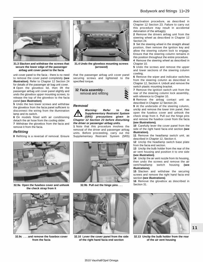
unit cover panel to the facia - there is no needto remove the cover panel completely (seeillustration). Refer to Chapter 12 Section 24for details of the passenger air bag unit cover.4 Open the glovebox lid, then lift thepassenger airbag unit cover panel slightly andundo the glovebox upper mounting screws, torelease the top of the glovebox to the faciapanel (see illustration).5 Undo the two lower screws and withdrawthe glovebox from the facia panel sufficient todisconnect the wiring from the illuminationlamp and its switch.6 On models fitted with air conditioningdetach the air hose from the cooling slider.7 Withdraw the glovebox from the facia andremove it from the facia.
Refitting8 Refitting is a reversal of removal. Ensure
that the passenger airbag unit cover panelsecuring screws and tightened to thespecified torque.
32 Facia assembly -removal and refitting 4
RemovalWarning: Refer to theSupplementary Restraint System(SRS) precautions given in
Chapter 12 Section 23 before disturbingthe driver or passenger airbag units.1 Note that this procedure involves theremoval of the driver and passenger airbagunits. Before proceeding, carry out theSupplementary Restraint System (SRS)
deactivation procedure, as described inChapter 12 Section 23. Failure to carry outthis procedure may result in accidentaldetonation of the airbag(s).2 Remove the drivers airbag unit from thesteering wheel as described in Chapter 12Section 24.3 Set the steering wheel in the straight aheadposition, then remove the ignition key andallow the steering column lock to engage.Ensure that the steering column remains inthis position throughout the entire procedure.4 Remove the steering wheel as described inChapter 10.5 Undo the screws and remove the upperand lower sections of the steering columncowling.6 Remove the wiper and indicator switchesfrom the steering column as described inChapter 12, Section 4. Unbolt and remove theswitch plastic mounting bracket.7 Remove the ignition switch unit from therear of the steering column lock assembly,with reference to Chapter 10.8 Remove the airbag contact unit asdescribed in Chapter 12 Section 24.9 At the underside of the steering column,unclip and remove the lower trim panel, thenopen the fusebox cover and unhook thecheck strap from it. Pull out the hinge pinsand remove the fusebox cover from the facia(see illustrations).10 Carefully lever the cover panel from theside of the right hand facia end section (seeillustration).11 Remove the headlamp switch unit, asdescribed in Chapter 12, Section 4.12 Unclip the headlamp switch base platefrom the facia end section.13 Unclip the bulb holder from the rear of theair vent housing and position it to one side(see illustration).14 Unclip the air vent nozzle from its housing,then undo the screws and remove the airvent/headlamp switch housing (seeillustrations).15 Slacken and withdraw the securingscrews and remove the right hand facia endsection (see illustrations).16 Remove the glovebox as described inSection 31.
Bodywork and fittings 11•29
11
31.3 Slacken and withdraw the screws thatsecure the lower edge of the passenger
airbag unit cover panel to the facia
31.4 Undo the glovebox mounting screws(arrowed)
32.9a Open the fusebox cover and unhookthe check strap from it
32.9b Pull out the hinge pins . . .
32.9c . . . and remove the fusebox coverfrom the facia
32.10 Lever the cover panel from the sideof the right hand facia end section
32.13 Unclip the bulb holder from the rearof the air vent housing
3510 Vauxhall/Opel Omega

17 Unclip the cover panel from the left handfacia end section.18 Unclip the bulb holder from the rear of theair vent housing and position it to one side.19 Slacken and withdraw the securing
screws then detach the nozzle from the lefthand air vent housing (see illustrations).20 Undo the securing screws and remove theleft hand end section from the facia (seeillustrations).
21 Remove the passenger airbag asdescribed in Chapter 12 Section 24, thenunbolt and remove the passenger airbagmounting bracket.22 Carefully prise the two nozzles from the
11•30 Bodywork and fittings
32.14a Unclip the air vent nozzle from itshousing . . .
32.14b . . . then undo the screws . . . 32.14c . . . and remove the airvent/headlamp switch housing
32.22a Carefully prise the two nozzlesfrom the centre air vent housing . . .
32.22b . . . then undo the securing screws . . .
32.22c . . . and remove the vent housingfrom the facia
32.19b . . . then detach the nozzle from theleft hand air vent housing
32.20a Undo the securing screws . . . 32.20b . . . and remove the left hand endsection from the facia
32.15a Slacken and withdraw the securingscrews . . .
32.15b . . . and remove the right hand faciaend section
32.19a Slacken and withdraw the securingscrews . . .
3510 Vauxhall/Opel Omega

centre air vent housing, then undo thesecuring screws and remove the vent housingfrom the facia (see illustrations).23 Remove the instrument pack as describedin Chapter 12 Section 9.24 Remove the heater control panel (orElectronic Climate Control panel, as applicable)from the facia as described in Chapter 3.25 Remove the centre console as describedin Section 30.26 Slacken and withdraw the screwssecuring the fusebox panel and the relaypanel to the facia. Pull the panels away fromthe facia slightly, leaving the wring harnessesattached.27 Working underneath the facia on thepassengers side, remove the securing screwsand detach the moulded air duct that runsfrom the air distributor unit to the left handend of the facia.28 Withdraw the exit vent and disconnect themoulded air ducting that runs from the air
distributor housing to the right hand end ofthe facia.29 Release the main wiring harness from themounting on the facia, behind the relay baseplate, by compressing the press-stud clip witha pair of pliers and pushing it through itsmounting hole. Release the three clips fromthe panel behind the heater/ECC controlpanel mounting aperture in a similar manner(see illustrations).30 Release the main wiring harness from thecable tie clips, located inside the facia, abovethe transmission tunnel. Access to the clips(via the radio/cassette mounting aperture) isextremely limited. Take great care to avoiddamaging the wiring harness during thisoperation, as the air bag control unit wiring isrouted through this section of the harness.31 Remove the Electronic Climate Control(ECC) sun sensor from the top of the facia(where applicable) with reference to Chapter 3,Section 13.
32 Unbolt and remove the driver andpassenger grab handles, then unclip the trimpanels from both A-pillars (see illustrations).33 Slacken and withdraw the facia securingbolts; there are seven bolts in total: one at thelower edge of the facia, in front of the gearlever, two each at the extreme right and lefthand ends of the facia, one behind theinstrument panel mounting aperture, and oneadjacent to the upper right hand corner of thepassenger air bag mounting bracket aperture.34 Carefully withdraw the facia from thebulkhead, ensuring that the wiring harnesshas been completely released from the rear ofthe facia assembly (see illustration). Removethe assembly from the vehicle.
Refitting35 Refit the facia by following the reversalprocedure in reverse. If a new facia assembly isto be fitted, make sure that the airbag warningstickers are transferred from the old facia.
Bodywork and fittings 11•31
11
32.32a Unbolt and remove the driver andpassenger grab handles . . .
32.32b . . . then unclip the trim panels fromboth A-pillars
32.34 Carefully withdraw the facia fromthe bulkhead
3510 Vauxhall/Opel Omega
32.29a Release the main wiring harness from the mounting on thefacia, behind the relay base plate, by compressing the press-stud
clip with a pair of pliers . . .
32.29b . . . release the three clips from the panel behind theheater/ECC control panel mounting aperture in a similar manner

3510 Vauxhall/Opel Omega
12•1
12
Chapter 12Body electrical system
System type . . . . . . . . . . . . . . . . . . . . . . . . . . . . . . . . . . . . . . . . . . . 12-volt negative earth
FusesMain interior fusebox
Fuse Rating Circuits protectedF1 30 . . . . . . . . . . . . . . . . . . . . . . . . . . . . . . . . . . . . . . . . . . . . . . . . Front window motorsF2 15 . . . . . . . . . . . . . . . . . . . . . . . . . . . . . . . . . . . . . . . . . . . . . . . . Brake lights, Hazard lightsF3 30 . . . . . . . . . . . . . . . . . . . . . . . . . . . . . . . . . . . . . . . . . . . . . . . . Windscreen/rear screen wash/wipe systemF4 15 . . . . . . . . . . . . . . . . . . . . . . . . . . . . . . . . . . . . . . . . . . . . . . . . Cooling fanF5 30 . . . . . . . . . . . . . . . . . . . . . . . . . . . . . . . . . . . . . . . . . . . . . . . . Electric seatsF6 20 . . . . . . . . . . . . . . . . . . . . . . . . . . . . . . . . . . . . . . . . . . . . . . . . Audio equipmentF7 30 . . . . . . . . . . . . . . . . . . . . . . . . . . . . . . . . . . . . . . . . . . . . . . . . Rear window motorsF8 10 . . . . . . . . . . . . . . . . . . . . . . . . . . . . . . . . . . . . . . . . . . . . . . . . Daytime driving lightsF9 10 . . . . . . . . . . . . . . . . . . . . . . . . . . . . . . . . . . . . . . . . . . . . . . . . Automatic transmissionF10 . . . . . . . . . . . . . . . . . . . . . . . . . . . . . . . . . . . . . . . . . . . . . . . . . BlankF11 10 . . . . . . . . . . . . . . . . . . . . . . . . . . . . . . . . . . . . . . . . . . . . . . . . Heated door mirrorsF12 20 . . . . . . . . . . . . . . . . . . . . . . . . . . . . . . . . . . . . . . . . . . . . . . . . Interior lights, Radio, Central locking remote receiver, Direction
indicators, Hazard lights, Multi-function displayF13 10 . . . . . . . . . . . . . . . . . . . . . . . . . . . . . . . . . . . . . . . . . . . . . . . . Electric exterior door mirrorsF14 30 . . . . . . . . . . . . . . . . . . . . . . . . . . . . . . . . . . . . . . . . . . . . . . . . Power steering, Cigarette lighter, Air circulation system, Air
conditioning system, Heated rear window, Heated seatsF15 20 . . . . . . . . . . . . . . . . . . . . . . . . . . . . . . . . . . . . . . . . . . . . . . . . Reversing lights, Glove compartment light, Automatic level control
system, Cruise control system, Sunroof, Instrument illumination,Headlight range adjustment
F16 20 . . . . . . . . . . . . . . . . . . . . . . . . . . . . . . . . . . . . . . . . . . . . . . . . Fog lightsF17 20 . . . . . . . . . . . . . . . . . . . . . . . . . . . . . . . . . . . . . . . . . . . . . . . . HornF18 20 . . . . . . . . . . . . . . . . . . . . . . . . . . . . . . . . . . . . . . . . . . . . . . . . Fuel pumpF19 10 . . . . . . . . . . . . . . . . . . . . . . . . . . . . . . . . . . . . . . . . . . . . . . . . Anti-lock braking/traction control systemF20 20 . . . . . . . . . . . . . . . . . . . . . . . . . . . . . . . . . . . . . . . . . . . . . . . . Central locking, Courtesy lights
Anti-theft alarm system and engine immobiliser - general information . . . . . . . . . . . . . . . . . . . . . . . . . . . . . . . . . . . . . . . . . . . 22
Battery - removal and refitting . . . . . . . . . . . . . . . . . . .See Chapter 5ABattery check and maintenance . . . . . . . . . . . . . . .See Weekly checksBulbs (exterior lights) - renewal . . . . . . . . . . . . . . . . . . . . . . . . . . . . . 5Bulbs (interior lights) - renewal . . . . . . . . . . . . . . . . . . . . . . . . . . . . . 6Cigarette lighter - removal and refitting . . . . . . . . . . . . . . . . . . . . . . . 12Clock/multi-function display unit - removal and refitting . . . . . . . . . . 11Cruise control system - component removal and refitting . . . . . . . . 25Electrical fault-finding - general information . . . . . . . . . . . . . . . . . . . 2Electrical systems check . . . . . . . . .See Chapter 1 and Weekly checksExterior light units - removal and refitting . . . . . . . . . . . . . . . . . . . . . 7Fuses and relays - general information . . . . . . . . . . . . . . . . . . . . . . . 3General information and precautions . . . . . . . . . . . . . . . . . . . . . . . . 1Headlight beam alignment - general information . . . . . . . . . . . . . . . 8Horn(s) - removal and refitting . . . . . . . . . . . . . . . . . . . . . . . . . . . . . . 14Instrument panel - removal and refitting . . . . . . . . . . . . . . . . . . . . . . 9Instrument panel components - removal and refitting . . . . . . . . . . . 10
Loudspeakers - removal and refitting . . . . . . . . . . . . . . . . . . . . . . . . 20Radio aerial - removal and refitting . . . . . . . . . . . . . . . . . . . . . . . . . . 21Radio/cassette/CD player - removal and refitting . . . . . . . . . . . . . . . 19Supplementary Restraint System (SRS) - general information,
precautions and system de-activation . . . . . . . . . . . . . . . . . . . . . . 23Supplementary Restraint System (SRS) components - removal and
refitting . . . . . . . . . . . . . . . . . . . . . . . . . . . . . . . . . . . . . . . . . . . . . . 24Switches - removal and refitting . . . . . . . . . . . . . . . . . . . . . . . . . . . . 4Tailgate wiper motor - removal and refitting . . . . . . . . . . . . . . . . . . . 17Washer fluid level check . . . . . . . . . . . . . . . . . . . . .See Weekly checksWindscreen wiper motor and linkage - removal and refitting . . . . . . 16Windscreen/tailgate/headlight washer system components - removal
and refitting . . . . . . . . . . . . . . . . . . . . . . . . . . . . . . . . . . . . . . . . . . 18Wiper arm - removal and refitting . . . . . . . . . . . . . . . . . . . . . . . . . . . 15Wiper blades check and renewal . . . . . . . . . . . . . . .See Weekly checksWiring diagrams - general information . . . . . . . . . . . . . . . . . . . . . . . 26Xenon headlight beam levelling system - component removal and
refitting . . . . . . . . . . . . . . . . . . . . . . . . . . . . . . . . . . . . . . . . . . . . . . 13
Specifications
Contents
Easy, suitable fornovice with littleexperience
Fairly easy, suitablefor beginner withsome experience
Fairly difficult,suitable for competentDIY mechanic
Difficult, suitable forexperienced DIYmechanic
Very difficult,suitable for expert DIYor professional
Degrees of difficulty
54321

Fuses (continued)Fuse Rating Circuits protectedF21 10 . . . . . . . . . . . . . . . . . . . . . . . . . . . . . . . . . . . . . . . . . . . . . . . . Main beam (left)F22 15 . . . . . . . . . . . . . . . . . . . . . . . . . . . . . . . . . . . . . . . . . . . . . . . . Dipped beam (left), Headlight range adjustmentF23 10 . . . . . . . . . . . . . . . . . . . . . . . . . . . . . . . . . . . . . . . . . . . . . . . . Parking and tail lightsF24 20 . . . . . . . . . . . . . . . . . . . . . . . . . . . . . . . . . . . . . . . . . . . . . . . . Coolant heaterF25 20 . . . . . . . . . . . . . . . . . . . . . . . . . . . . . . . . . . . . . . . . . . . . . . . . SunroofF26 10 . . . . . . . . . . . . . . . . . . . . . . . . . . . . . . . . . . . . . . . . . . . . . . . . Number plate lights, Headlight washer systemF27 20 . . . . . . . . . . . . . . . . . . . . . . . . . . . . . . . . . . . . . . . . . . . . . . . . Automatic level control systemF28 20 . . . . . . . . . . . . . . . . . . . . . . . . . . . . . . . . . . . . . . . . . . . . . . . . Fog tail lightF29 20 . . . . . . . . . . . . . . . . . . . . . . . . . . . . . . . . . . . . . . . . . . . . . . . . Caravan/trailer constant current supplyF30 10 . . . . . . . . . . . . . . . . . . . . . . . . . . . . . . . . . . . . . . . . . . . . . . . . Parking/tail lights (right)F31 15 . . . . . . . . . . . . . . . . . . . . . . . . . . . . . . . . . . . . . . . . . . . . . . . . Dipped beam (right), Headlight range adjustmentF32 10 . . . . . . . . . . . . . . . . . . . . . . . . . . . . . . . . . . . . . . . . . . . . . . . . Main beam (right)F33 30 . . . . . . . . . . . . . . . . . . . . . . . . . . . . . . . . . . . . . . . . . . . . . . . . Blower motor
1 General information andprecautions
Warning: Before carrying out anywork on the electrical system,read through the precautions
given in Safety first! at the beginning ofthis manual, and in Chapter 5A.1 The electrical system is of 12-volt negativeearth type. Power for the lights and allelectrical accessories is supplied by a leadacid type battery, which is charged by thealternator.2 This Chapter covers repair and serviceprocedures for the various electricalcomponents not associated with the engine.Information on the battery, alternator andstarter motor can be found in Chapter 5A.3 It should be noted that, before working onany component in the electrical system, thebattery negative terminal should first bedisconnected, to prevent the possibility ofelectrical short-circuits and/or fires.4 At regular intervals, carefully check therouting of the wiring harness, ensuring that itis correctly secured by the clips or tiesprovided so that it cannot chafe against othercomponents. If evidence is found of theharness having chafed against othercomponents, repair the damage and ensurethat the harness is secured or protected sothat the problem cannot occur again.Caution: If the audio unit fitted to thevehicle is one with an anti-theft securitycode, refer to the audio unit anti-theftprecautions in the Reference Section ofthis manual before disconnecting thebattery.
2 Electrical fault-finding -general information
Note: Refer to the precautions given in Safetyfirst! (at the beginning of this manual) and toSection 1 of this Chapter before starting work.
The following tests relate to testing of themain electrical circuits, and should not beused to test sensitive electronic circuits (suchas anti-lock braking systems), particularlywhere an electronic control module is used.
General1 A typical electrical circuit consists of anelectrical component, any switches, relays,motors, fuses, fusible links or circuit breakersrelated to that component, and the wiring andconnectors that link the component to boththe battery and the chassis. To help topinpoint a problem in an electrical circuit,wiring diagrams are included at the end of thischapter.2 Before attempting to diagnose an electricalfault, first study the appropriate wiringdiagram to obtain a complete understandingof the components included in the particularcircuit concerned. The possible sources of afault can be narrowed down by notingwhether other components related to thecircuit are operating properly. If severalcomponents or circuits fail at one time, theproblem is likely to be related to a shared fuseor earth connection.3 Electrical problems usually stem fromsimple causes, such as loose or corrodedconnections, a faulty earth connection, ablown fuse, a melted fusible link, or a faultyrelay (refer to Section 3 for details of testingrelays). Visually inspect the condition of allfuses, wires and connections in a problemcircuit before testing the components. Usethe wiring diagrams to determine whichterminal connections will need to be checked,to pinpoint the trouble-spot.4 The basic tools required for electrical fault-finding include the following.a) A circuit tester or voltmeter (a 12-volt bulb
with a set of test leads can also be usedfor certain tests).
b) A self-powered test light (sometimesknown as a continuity tester).
c) An ohmmeter (to measure resistance).d) A battery.e) A set of test leads.f) A jumper wire, preferably with a circuit
breaker or fuse incorporated, which can
be used to bypass suspect wires orelectrical components.
Before attempting to locate a problem withtest instruments, use the wiring diagram todetermine where to make the connections.5 To find the source of an intermittent wiringfault (usually due to a poor or dirtyconnection, or damaged wiring insulation), a‘wiggle’ test can be performed on the wiring.This involves moving the wiring by hand, tosee if the fault occurs as the wiring is moved.It should be possible to narrow down thesource of the fault to a particular section ofwiring. This method of testing can be used inconjunction with any of the tests described inthe following sub-Sections.6 Apart from problems due to poorconnections, two basic types of fault canoccur in an electrical circuit - open-circuit andshort-circuit.7 Open-circuit faults are caused by a breaksomewhere in the circuit, which preventscurrent from flowing. An open-circuit fault willprevent a component from working, but willnot cause the relevant circuit fuse to blow.8 Short-circuit faults are caused by a ‘short’somewhere in the circuit, which allows thecurrent flowing in the circuit to ‘escape’ alongan alternative route, usually to earth. Short-circuit faults are normally caused by abreakdown in wiring insulation, which allows afeed wire to touch either another wire, or anearthed component such as the bodyshell. Ashort-circuit fault will normally cause therelevant circuit fuse to blow.
Finding an open-circuit9 To check for an open-circuit, connect onelead of a circuit tester or voltmeter to eitherthe negative battery terminal or a known goodearth.10 Connect the other lead to a connectorin the circuit being tested, preferably nearestto the battery or fuse.11 Switch on the circuit, remembering thatsome circuits are live only when the ignitionswitch is moved to a particular position.12 If voltage is present (indicated either bythe tester bulb lighting or a voltmeter reading,as applicable), this means that the section of
12•2 Body electrical system
3510 Vauxhall/Opel Omega

the circuit between the relevant connectorand the battery is problem-free.13 Continue to check the remainder of thecircuit in the same fashion.14 When a point is reached at which novoltage is present, the problem must liebetween that point and the previous test pointwith voltage. Most problems can be traced toa broken, corroded or loose connection.
Finding a short-circuit15 To check for a short-circuit, firstdisconnect the load(s) from the circuit (loadsare the components that draw current from acircuit, such as bulbs, motors, heatingelements, etc.).16 Remove the relevant fuse from the circuit,and connect a circuit tester or voltmeter to thefuse connections.17 Switch on the circuit, remembering thatsome circuits are live only when the ignitionswitch is moved to a particular position.18 If voltage is present (indicated either bythe tester bulb lighting or a voltmeter reading,as applicable), this means that there is ashort-circuit.19 If no voltage is present, but the fuse stillblows with the load(s) connected, thisindicates an internal fault in the load(s).
Finding an earth fault20 The battery negative terminal isconnected to ‘earth’ (the metal of theengine/transmission and the car body), andmost systems are wired so that they onlyreceive a positive feed. The current returningthrough the metal of the car body. Thismeans that the component mounting and thebody form part of that circuit. Loose orcorroded mountings can therefore cause arange of electrical faults, ranging from totalfailure of a circuit, to a puzzling partial fault. Inparticular, lights may shine dimly (especiallywhen another circuit sharing the same earthpoint is in operation). Motors (eg wipermotors or the radiator cooling fan motor) mayrun slowly, and the operation of one circuitmay have an affect on another. Note that onmany vehicles, earth straps are usedbetween certain components, such as theengine/transmission and the body, usually
where there is no metal-to-metal contactbetween components, due to flexible rubbermountings, etc.21 To check whether a component isproperly earthed, disconnect the battery, andconnect one lead of an ohmmeter to a knowngood earth point. Connect the other lead tothe wire or earth connection being tested. Theresistance reading should be zero; if not,check the connection as follows.22 If an earth connection is thought to befaulty, dismantle the connection, and cleanback to bare metal both the bodyshell and thewire terminal or the component earthconnection mating surface. Be careful toremove all traces of dirt and corrosion, thenuse a knife to trim away any paint, so that aclean metal-to-metal joint is made. Onreassembly, tighten the joint fastenerssecurely; if a wire terminal is being refitted,use serrated washers between the terminaland the bodyshell, to ensure a clean andsecure connection. When the connection isremade, prevent the onset of corrosion in thefuture by applying a coat of petroleum jelly orsilicone-based grease.
3 Fuses and relays -general information
Fuses1 Fuses are designed to break a circuit when apredetermined current is reached, to protect thecomponents and wiring which could bedamaged by excessive current flow. Anyexcessive current flow will be due to a fault in thecircuit, usually a short-circuit (see Section 2).2 The main fuses and relays are located in apanel beneath a cover under the driver’s sideof the facia (see illustration). The circuitsprotected by the various fuses and relays aremarked on the inside of the panel cover.3 Additional fuses and relays are housed inan auxiliary fusebox, located in the enginecompartment. On some models, a secondaryauxiliary fusebox, clipped to the top of thebattery houses a number of fusible links (seeillustrations).
4 A blown fuse or fusible link can berecognised from its melted or broken wire.5 To remove a fuse, first ensure that therelevant circuit is switched off. Then open thecover and pull the relevant fuse from the panelusing the tweezers supplied. If desired, thelower end of the panel can be tilted forwards,after releasing the retaining clip, to improveaccess.6 Before renewing a blown fuse, trace andrectify the cause, and always use a fuse of thecorrect rating. Never substitute a fuse of ahigher rating, or make temporary repairs usingwire or metal foil, as more serious damage, oreven fire, could result.7 Spare fuses are generally provided in theblank terminal positions in the fusebox.8 Note that the fuses are colour-coded, seeSpecifications. Refer to the wiring diagramsfor details of the fuse ratings and the circuitsprotected.
Relays9 A relay is an electrically-operated switch,which is used for the following reasons:a) A relay can switch a heavy current
remotely from the circuit in which thecontrol current is flowing, allowing the useof lighter-gauge wiring and control switchcontacts.
b) A relay can receive more than one controlinput, unlike a mechanical switch.
c) A relay can have a timer function.10 If a circuit or system controlled by a relaydevelops a fault, and the relay is suspect,operate the system. If the relay is functioning,it should be possible to hear it click as it isenergised. If this is the case, the fault lies withthe components or wiring of the system. If therelay is not being energised, then either therelay is not receiving a main supply or aswitching voltage, or the relay itself is faulty.Testing is by the substitution of a known goodunit, but be careful - while some relays areidentical in appearance and in operation,others look similar but perform differentfunctions.11 To remove a relay, first ensure that therelevant circuit is switched off. The relay canthen simply be pulled out from the socket,and pushed back into position.
Body electrical system 12•3
12
3.2 The main fuses and relays are locatedin a panel beneath a cover under the
driver’s side of the facia
3.3a Additional fuses and relays arehoused in an auxiliary fusebox, located in
the engine compartment
3.3b On some models, a secondaryauxiliary fusebox, clipped to the top of thebattery houses a number of fusible links
3510 Vauxhall/Opel Omega

4.12a Depress the locking catches at theside of the switch unit . . .
4 Switches -removal and refitting 3
Ignition switch/steering column lock cylinder1 Refer to the information given in Chapter 10.
Turn signal/wiper switch assembly2 The turn signal and wiper switch assembliesare removed identically.3 Remove the steering wheel as described inChapter 10.4 Unscrew the lever from the steering columntilt mechanism, then remove the screws anddetach the upper and lower sections of the
shroud panels from the steering column (seeillustrations).5 Depress the upper and lower locking tabs,then carefully slide the switch unit from thetop of the housing. Disconnect the wiring andremove the switch from the vehicle (seeillustrations).6 Refitting is a reversal of removal.
Facia-mounted push buttonswitches (except hazard warning)7 A small, hooked instrument or length ofwelding rod is required to pull the switch fromthe facia.8 Carefully insert the hooked instrumentbetween the switch and surround, then pullout the switch (see illustration).9 Disconnect the wiring from the switch.10 Refitting is a reversal of removal.
Lighting and fog light switch11 Carefully prise the cover panel from theend face of the drivers side of the faciamoulding.12 Using a pair of small screwdrivers orlengths of thin metal strip, depress the lockingcatches at the side of the switch unit, thencarefully slide it from the facia (seeillustrations). Prevent damage to the facia byplacing a wad of cloth beneath thescrewdrivers/metal strips. Note that theterminals on the rear of the switch locatedirectly in the sockets in the switch baseplate.13 To remove the fog light switch, release thetab and slide the switch from the base of theunit.14 Refitting is a reversal of removal.
12•4 Body electrical system
4.4a Unscrew the lever from the steeringcolumn tilt mechanism . . .
4.4b . . . then remove the screws from theend face . . .
4.4c . . . and underside . . .
4.5b . . . and disconnect the wiring 4.8 Removing a push button switch fromthe facia
4.4d . . . then detach the lower . . . 4.4e . . . and upper sections of the shroudpanels from the steering column
4.5a Depress the upper and lower lockingtabs, then carefully slide the switch unit
from the top of the housing . . .
3510 Vauxhall/Opel Omega

Hazard warning switch15 It is easier to remove the hazard warningswitch when in the ON position.16 Carefully unclip the cover from the switchbutton.17 Insert screwdrivers into the channel oneither side of the switch and carefully prise itfrom the facia, or use a small, hookedinstrument or length of welding rod to removethe switch (see illustration).18 Refitting is a reversal of removal.
Heater blower motor switch19 Refer to the information given in Chapter 3Section 8, for models with conventionalheating systems or Chapter 3 Section 13, formodels with Electronic Climate Control.
Stop light switch
Removal20 The stop-light switch is located on thepedal bracket in the driver’s footwell.21 To remove the switch, first remove thelower facia trim panel (see Chapter 11,Section 32), then disconnect the heating ductfor access to the switch.22 Disconnect the wiring plug from the top ofthe switch, then depress the switch lockingtabs and remove it from the pedal bracket.
Refitting23 Before refitting the switch, pull theactuation pin fully out.
24 Press the switch into its support bracket.25 Depress the brake pedal then pull theactuation pin fully out of the switch so that itcontacts the pedal. Now release the pedal toset the pin.26 Refit the heating duct and the lower faciatrim panel. Check the operation of the stop-light.
Courtesy light switch and rearluggage compartment switch27 Undo the retaining screw and withdrawthe switch (see illustration).28 Disconnect the wiring and tape it to thepanel to prevent it dropping out of reach.29 Make sure that the retaining screw makesgood contact with the body and switch. Ifnecessary clean the contact points.30 Refitting is a reversal of removal.
Electrically-operated windowswitch
Front window switches31 Refer to the information given in Chapter 11,Section 22.
Reversing light switch
Manual transmission32 Refer to the information given in Chapter 7A.
Automatic transmission33 Refer to the information given in Chapter 7B,Section 8.
5 Bulbs (exterior lights) -renewal 2
1 Whenever a bulb is renewed, note thefollowing points.a) Remember that, if the light has just been
in use, the bulb may be extremely hot.b) Do not touch the bulb glass with the
fingers, as this can result in early failure ora dull reflector.
c) Always check the bulb contacts andholder, ensuring that there is clean metal-to-metal contact between the bulb and itslive(s) and earth. Clean off any corrosionor dirt before fitting a new bulb.
d) Ensure that the new bulb is of the correctrating.
Headlight - dipped beam
Models with conventional headlights2 With the bonnet open, release fasteningscrews and detach the cover panel fromabove the headlight unit. Remove the coverfrom the rear of the relevant headlight (seeillustrations). Note that the outer headlight isfor dipped beam and the inner headlight is forthe main beam.3 Disconnect the wiring plug from the bulb(see illustration).
Body electrical system 12•5
12
4.12b . . . then carefully slide the switchfrom the facia
4.17 Removing the hazard warning switchbody from the facia
4.27 Undo the retaining screw (arrowed)and withdraw the switch -
Estate model shown
5.2a Detach the cover panel from abovethe headlight unit
5.2b Remove the cover from the rear ofthe relevant headlight
5.3 Disconnect the wiring plug from thebulb
3510 Vauxhall/Opel Omega

5.23 Rotate the indicator bulbholderanticlockwise to release it from the rear of
the light unit
4 Depress and unhook the retaining clip, thenwithdraw the bulb from the headlight (seeillustrations).5 When handling the new bulb, use a tissueor clean cloth, to avoid touching the glasswith the fingers; moisture and grease from theskin can cause blackening and rapid failure ofthis type of bulb. If the glass is accidentallytouched, wipe it clean using a small quantityof methylated spirit.6 Fit the new bulb using a reversal of theremoval procedure, making sure that the bulbis seated correctly in the cut-outs in theheadlight and that it is held is position with thespring clip.
Models with Xenon dischargeheadlights
Warning: The Xenon dischargebulbs operate at very highvoltage; before starting work,
disconnect the battery negative cable andremove the dipped beam fuses from theinterior fusebox.7 With the bonnet open, release fasteningscrew and detach the cover panel fromabove the headlight unit. If working on theleft hand headlight, first remove the batterywith reference to Chapter 5A. If working onthe right hand headlight, first remove the aircleaner housing with reference to Chap-ter 4A.8 At the rear of the headlight unit, undo thethree Torx screws and remove the protectivecap from the rear of the bulb connector.9 Turn the bulb connector to the left todisconnect it.10 Rotate the retaining ring to the left thenremove it from the rear of the bulb housing.11 Withdraw the bulb from its housing.12 Refitting is a reversal of removal. Ensurethat the headlight beam alignment is checkedby a Vauxhall dealer as soon as possible.
Headlight - main beam13 With the bonnet open, release fasteningscrews and detach the cover panel fromabove the headlight unit. Remove the coverfrom the rear of the relevant headlight (refer toillustration 5.2b). Note that the outer headlightis for dipped beam and the inner headlight isfor the main beam.14 Unplug the wiring connector from the rearof the bulb (see illustration).15 Carefully press down on the rear of thebulb, until it releases from its retaining clips.
16 Refitting is a reversal of removal. Pressthe bulb squarely into its housing until it is feltto engage with its retaining clips (seeillustration).
Models with Xenon dischargeheadlights
Warning: The Xenon dischargebulbs operate at very highvoltage; before starting work,
disconnect the battery negative cable andremove the main beam fuses from theinterior fusebox.17 The renewal procedure is similar to thatdescribed for the dipped beam bulb.
Front sidelight18 The front sidelight bulb is located at theside of the main beam headlight reflector.First remove the cover the rear of the mainbeam headlight (refer to illustration 5.2b).19 Withdraw the sidelight bulbholder fromthe rear of the headlight (see illustration).20 Remove the bulb from the holder (seeillustration).21 Fit the new bulb using a reversal of theremoval procedure.
Front direction indicator light22 With the bonnet open, release thefastening screw and detach cover panel fromabove the relevant headlight unit (refer toillustration 5.2a).23 Grasp the direction indicator bulbholderand rotate it anticlockwise to release it fromthe rear of the light unit (see illustration).
12•6 Body electrical system
5.4a Depress and unhook the retainingclip . . .
5.4b . . . then withdraw the bulb from theheadlight
5.14 Unplug the wiring connector from therear of the bulb
5.16 Press the bulb squarely into itshousing until it is felt to engage with its
retaining clips
5.19 Withdraw the sidelight bulbholderfrom the rear of the headlight
5.20 Remove the bulb from the holder
3510 Vauxhall/Opel Omega

24 Depress and twist the bulb and remove itfrom the bulbholder (see illustration).25 Fit the new bulb using a reversal of theremoval procedure.
Front foglight26 Remove the screws and detach the grilleadjacent to the relevant fog light, located inthe front bumper valence (see illustration).27 Undo the securing screws and pivot thefog light lens forwards (see illustration).28 Rotate the protective cap and remove itfrom the rear of the foglight (see illustration).29 Disconnect the wiring, then release the
spring clip and remove the bulb from thefoglight (see illustrations).30 Fit the new bulb using a reversal of theremoval procedure. When refitting the lightensure that the lug at the inner edge engagescorrectly with the recess in the front bumpervalence (see illustration).
Front direction indicator siderepeater light31 Using a small screwdriver, carefully leverthe side repeater light from the front wingmoulding (see illustration).32 Hold the bulbholder, then twist the lens toremove it (see illustration).
Body electrical system 12•7
12
5.24 Depress and twist the bulb andremove it from the bulbholder
5.26 Remove the screws and detach thegrille adjacent to the relevant fog light
5.30 When refitting the light ensure thatthe lug (arrowed) at the inner edge
engages correctly with the recess in thefront bumper valence
5.31 Carefully lever the side repeater lightfrom the front wing moulding
5.32 Hold the bulbholder, then twist thelens to remove it
5.29b . . . then release the spring clip . . . 5.29c . . . and remove the bulb from thefoglight
5.27 Undo the securing screws and pivotthe fog light lens forwards
5.28 Rotate the protective cap and removeit from the rear of the foglight
5.29a Disconnect the wiring . . .
3510 Vauxhall/Opel Omega

33 Pull the wedge-type bulb from thebulbholder (see illustration).34 Fit the new bulb using a reversal of theremoval procedure.
Rear light cluster - rear wing35 In the luggage compartment, remove theside trim cover. If working on the right-handside, remove the first aid kit and warningtriangle. If working on the left hand side, firstremove the spare wheel. On Estate models,the left-hand cover is removed by twisting thefastener.36 Depress the retaining lug in the middle ofthe rear light cluster, and withdraw thebulbholder from the rear light (seeillustration).37 Depress and twist the relevant bulb toremove it (see illustration).38 Fit the new bulb using a reversal of theremoval procedure.
Rear light cluster - boot lid39 Open the boot lid.40 Depress the retaining lugs at either side ofthe bulbholder, then withdraw the bulbholderfrom the rear of the light unit (seeillustration).41 Depress and twist the relevant bulb toremove it (see illustration).42 Fit the new bulb using a reversal of theremoval procedure.
Rear number plate light - Saloon models43 Open the bootlid, then depress the clipand remove the light unit from the bumper(see illustration).44 Unclip the lens from the light unit thendepress and twist the bulb from its contacts(see illustrations).45 Fit the new bulb using a reversal of theremoval procedure.
Rear number plate light - Estate models46 Open the tailgate halfway, then undo thescrews from the relevant light and withdrawthe light unit from under the handle moulding.47 Release the festoon type bulb from thespring contacts.48 Fit the new bulb using a reversal of theremoval procedure. Make sure that the bulb isheld firmly between the spring contacts, and ifnecessary pretension the contacts beforefitting the bulb.
High level stop light - Saloon models49 Unclip the cover from the high level stoplight (see illustration).50 Unplug the wiring at the connector (seeillustration).51 Unclip the bulbholder from the cover (seeillustration).
12•8 Body electrical system
5.33 Pull the wedge-type bulb from thebulbholder
5.36 Withdraw the bulbholder from therear light
5.37 Depress and twist the relevant bulbto remove it
5.44a Unclip the lens from the light unit . . . 5.44b . . . then depress and twist the bulbfrom its contacts
5.49 Unclip the cover from the high levelstop light
5.40 Withdraw the bulbholder from therear of the light unit
5.41 Depress and twist the relevant bulbto remove it
5.43 Depress the clip and remove the lightunit from the bumper
3510 Vauxhall/Opel Omega

52 Remove the bulb(s) as necessary.53 Fit the new bulb using a reversal of theremoval procedure.
High level stop light - Estate models54 With the tailgate open, unclip the centresection of the tailgate upper trim panelling.55 Rotate the relevant bulbholder to removeit from its bayonet contacts.56 Fit the new bulb using a reversal of theremoval procedure.
6 Bulbs (interior lights) -renewal 2
1 Whenever a bulb is renewed, note thefollowing points.a) Remember that, if the light has just been
in use, the bulb may be extremely hot.b) Do not touch the bulb glass with the
fingers, as this can result in early failure ora dull reflector.
c) Always check the bulb contacts andholder, ensuring that there is clean metal-to-metal contact between the bulb and itslive(s) and earth. Clean off any corrosionor dirt before fitting a new bulb.
d) Ensure that the new bulb is of the correctrating.
Front interior light2 Ensure that the bulb contacts are not live,
by closing all doors and ensuring that the lightswitch is off. Carefully prise the lens from theinterior light using a screwdriver (seeillustration).3 Remove the relevant bulb from its contacts(see illustration). The main light is a festoonstyle bulb which can be prised from its springloaded contacts, while the map reading lightbulbs can be pulling them from their contacts.4 Fit the new bulb using a reversal of theremoval procedure.
Rear interior light5 Carefully prise the interior light from thedoor upper trim panel (see illustration).6 Remove the bulb from its contacts (seeillustration).7 Fit the new bulb using a reversal of theremoval procedure. Make sure that the bulb isheld firmly between the spring contacts.
Luggage compartment interiorlight8 Carefully prise the light from the side trim(see illustration).9 Remove the bulb from its contacts (seeillustration).10 Fit the new bulb using a reversal of theremoval procedure. Make sure that the bulb isheld firmly between the spring contacts.
Glovebox light11 With the glovebox open, carefully priseout the light unit.12 Remove the festoon type bulb from thespring contacts.13 Fit the new bulb using a reversal of theremoval procedure. Make sure that the bulb isheld firmly between the spring contacts.
Body electrical system 12•9
12
5.50 Unplug the wiring at the connector 5.51 Unclip the bulbholder from the cover
6.2 Carefully prise the lens from the frontinterior light using a screwdriver
6.6 Remove the bulb from its contacts 6.8 Carefully prise the light from theluggage compartment side trim
6.9 Remove the bulb from its contacts
6.3 Remove the relevant bulb from itscontacts
6.5 Carefully prise the rear interior lightfrom the door upper trim panel
3510 Vauxhall/Opel Omega

Door mounted interior light14 Carefully lever the light from the door trimpanel (see illustration).15 Remove the heat shield, then remove thefestoon type bulb from the spring contacts(see illustrations).16 Fit the new bulb using a reversal of theremoval procedure. Make sure that the bulb isheld firmly between the spring contacts.
Instrument panel illuminationand warning light bulbs17 Remove the instrument panel asdescribed in Section 9.18 The central bulbholders are for theinstrument illumination and the lowerbulbholders on the circuit board are thewarning tell-tale lights.19 To remove the bulbs twist and turn thebulbholder and remove from the instrument
panel, then, where applicable, remove the bulbfrom the bulbholder. Note that some bulbscannot be removed from their bulbholders(see illustration).20 Fit the new bulb using a reversal of theremoval procedure.
Light switch illumination21 Remove the light switch as described inSection 4.22 Using a screwdriver, twist the bulbholderfrom the rear of the switch.23 Fit the new bulb using a reversal of theremoval procedure.
Clock/multi-function display unitillumination24 Remove the instrument panel asdescribed in Section 9. The clock/multi-function display unit is located on the rear ofthe instrument panel.
25 Using a screwdriver if necessary, twist therelevant bulbholder from the rear of thedisplay unit (see illustration).26 Fit the new bulb using a reversal of theremoval procedure.
Heater control illumination27 Remove the heater controlpanel/Electronic Climate Control panel asdescribed in Chapter 3.28 Remove the relevant bulb from the rear ofthe panel.29 Fit the new bulb using a reversal of theremoval procedure.
7 Exterior light units -removal and refitting 3
HeadlightWarning: The discharge bulbsfitted to models with Xenonheadlights operate at very high
voltage; before starting work, disconnectthe battery negative cable and removefuses F22 and F31 from the interiorfusebox.
Removal1 Remove the radiator grille as described inChapter 11. Release the fastening screws andremove the cover panel from the above theheadlight unit.2 Undo the securing screw and remove thetrim panel from underneath the headlight unit(see illustration). Where applicable,disconnect the nozzle from the headlightwasher hose.3 Disconnect the wiring plugs from the rear ofthe headlight (see illustration). On modelswith Xenon headlights, disconnect the wiringconnectors from the rear of the bulbs asdescribed for bulb renewal in Section 5.4 Unscrew the three headlight mounting boltslocated above and below the unit, andwithdraw the headlight from the front of thevehicle (see illustrations).5 If necessary, the headlight range controlservo may be removed by twisting it anti-clockwise (see illustration).
12•10 Body electrical system
6.14 Carefully lever the light unit from thedoor trim panel
6.15a Remove the heat shield . . . 6.15b . . . then remove the bulb from thespring contacts
7.2 Remove the trim panel fromunderneath the headlight unit
6.19 Removing instrument packillumination bulb
6.25 Removing a clock/multi-functiondisplay unit illumination bulb
7.3 Disconnect the wiring plugs from therear of the headlight
3510 Vauxhall/Opel Omega

Refitting6 Refitting is a reversal of removal, but makesure that the locating lug on the headlightengages with the corresponding hole in thefront valance and, on completion, have theheadlight beam alignment checked at theearliest opportunity.
Front direction indicator light7 The direction indicator is integral with theheadlight unit.
Front foglight
Removal8 Remove the front bumper as described inChapter 11.9 Unscrew the three mounting bolts andremove the foglight from the bumper, thendisconnect the wiring (see illustration).
Refitting10 Refitting is a reversal of removal.
Front direction indicator siderepeater light11 The procedure is as described in Section5 for bulb renewal. The wiring connector canbe unplugged from the rear of the bulbholderto allow removal of the light unit and thebulbholder as a complete assembly.
Rear light cluster
Bootlid cluster12 Open the bootlid and unclip thebulbholder from the rear of the light unit (seeSection 5).13 Unplug the wiring connector from thebulbholder (see illustration).14 Remove the nuts/screws and detach the
light cluster from the bootlid (seeillustrations).15 Refitting is a reversal of removal.
Rear wing cluster16 In the luggage compartment, removethe side trim cover. If working on the right-hand side, remove the first aid kit and warningtriangle. If working on the left hand side,remove the spare wheel. On Estate models,the left-hand cover is removed by twisting thefastener.17 Depress the retaining lug in the middle ofthe rear light cluster, and withdraw thebulbholder from the rear light (see Section 5).Unplug the wiring connector from the edge ofthe bulbholder.18 Slacken and withdraw the securingscrews/nuts and withdraw the light clusterfrom the rear of the vehicle (see illustrations).
Body electrical system 12•11
12
7.4a Unscrew the headlight mountingbolts located above . . .
7.4b . . . and below the unit . . . 7.4c . . . and withdraw the headlight fromthe front of the vehicle
7.14a Remove the nuts/screws . . . 7.14b . . . and detach the light cluster fromthe bootlid
7.5 The headlight range control servo maybe removed by twisting it anti-clockwise
7.9 Unscrew the three mounting bolts(arrowed) and remove the foglight from the
bumper
7.13 Unplug the wiring connector from thebulbholder
7.18a Slacken and withdraw the securingscrews/nuts (saloon models) . . .
3510 Vauxhall/Opel Omega

Take care not to damage the vehicle paint-work.19 Refitting is a reversal of removal.
8 Headlight beam alignment -general information 5
1 Accurate adjustment of the headlight beamis only possible using optical beam-settingequipment, and this work should therefore becarried out by a Vauxhall/Opel dealer orsuitably-equipped workshop.2 For reference, the headlights can beadjusted using the adjuster assemblies fittedto the front upper outer mounting and to therear inner mounting. The inner screw is forhorizontal adjustment and the outer one forvertical adjustment.3 All models have an electrically-operatedheadlight beam adjustment range system,
controlled via a switch in the facia. Therecommended settings are as follows.0 Front seat(s) occupied1 All seats occupied2 All seats occupied, and load in luggage
compartment3 Driver’s seat occupied and load in the
luggage compartmentNote: When adjusting the headlight aim,ensure that the switch is set to position 0.4 On Estate models with automatic self-levelling control, the headlight range adjust-ment should be reduced by one setting aftercompleting approximately 3 km (1.8 miles).
Models with Xenon headlights5 Due to the intensity of the light emitted byXenon discharge headlight bulbs, it is vitallyimportant that the operation of the automaticbeam level control system is checked by aVauxhall dealer, using dedicated electronictest equipment. Failure to do so could result inother road uses being severely dazzled byyour headlights. This applies equally to themain and dipped beam headlights.
9 Instrument panel -removal and refitting 2
Removal1 Disconnect the battery negative cable andposition it away from the terminal.2 Remove the steering wheel as described inChapter 10, then remove the securing screws
and detach the upper and lower shroudpanels from the steering column.3 Carefully prise the centre and driver’s sideair vents from the facia, using a smallscrewdriver or alternatively feeler blades todepress the side clips. Place a wad of clothbeneath the screwdriver to prevent damage.Remove the screws and withdraw the air venthousing from the facia (refer to the illustrationsin Chapter 11, Section 32.5 Undo the two mounting screws, detach themounting bracket and withdraw the instrumentpanel from the facia (see illustrations).6 Carefully pivot the instrument paneltowards the passenger side of the car, untilthe fixed multiway wiring connector is felt todisengage.7 Disconnect the wiring from the rear of themulti-function display unit and then withdrawthe instrument panel from the facia (seeillustration).
Refitting8 Refitting is a reversal of removal, but checkthe operation of all the warning andillumination bulbs on completion.
10 Instrument panelcomponents -removal and refitting
2Removal1 With the instrument panel removed asdescribed in Section 9, remove the warning andillumination bulbs as described in Section 6.
12•12 Body electrical system
7.18b Slacken and withdraw the securingscrews/nuts (estate models) . . .
7.18c . . . and withdraw the light clusterfrom the rear of the vehicle
(saloon models) . . .7.18d . . . and withdraw the light cluster
from the rear of the vehicle (estate models)
9.5b . . . and lower mounting bracketscrews . . .
9.5a Undo the left hand . . .
9.5c . . . and withdraw the instrumentpanel from the facia
9.7 Disconnect the wiring from the rear ofthe multi-function display unit
3510 Vauxhall/Opel Omega
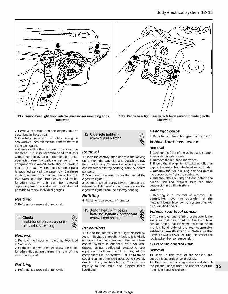
2 Remove the multi-function display unit asdescribed in Section 11.3 Carefully release the clips using ascrewdriver, then release the front frame fromthe main housing.4 Gauges within the instrument pack can berenewed, but it is recommended that thiswork is carried by an automotive electronicsspecialist, due the delicate nature of thecomponents involved. Note that on modelsbuilt from 1998 onwards, the instrument packis supplied as a single assembly. On thesemodels, although the illumination bulbs, tell-tale warning bulbs, front cover and multi-function display unit can be renewedseparately from the instrument pack, it is notpossible to renew individual gauges.
Refitting5 Refitting is a reversal of removal.
11 Clock/multi-function display unit -removal and refitting
2Removal1 Remove the instrument panel as describedin Section 9.2 Undo the screws then withdraw the multi-function display unit from the rear of theinstrument panel.
Refitting3 Refitting is a reversal of removal.
12 Cigarette lighter -removal and refitting 2
Removal1 Open the ashtray, then depress the lockingtab at the right hand side and detach the trayfrom its housing. Remove the securing screwand withdraw ashtray housing from the centreconsole.2 Disconnect the wiring from the rear of thecigarette lighter.3 Using a small screwdriver, release theretainer and illumination ring then remove thecigarette lighter from the ashtray housing.
Refitting4 Refitting is a reversal of removal.
13 Xenon headlight beamlevelling system - componentremoval and refitting
4Precautions1 Due to the intensity of the light emitted byXenon discharge headlight bulbs, it is vitallyimportant that the operation of the beam levelcontrol system is checked by a Vauxhalldealer, using dedicated electronic testequipment, following work on any of thecomponents in the system. Failure to do socould result in other road uses being severelydazzled by your headlights. This appliesequally to the main and dipped beamheadlights.
Headlight bulbs2 Refer to the information given in Section 5.
Vehicle front level sensor
Removal3 Jack up the front of the vehicle and supportit securely on axle stands.4 Remove the left hand roadwheel.5 Ensure that the ignition is switched off, thenunplug the wiring from the level sensor body.6 Unscrew the two securing bolt and detachthe sensor body from the subframe.7 Unscrew the securing bolt and detach thesensor link rod bracket from the frontsuspension (see illustration).
Refitting8 Refitting is a reversal of removal. Oncompletion have the operation of theheadlight beam level control system checkedby a Vauxhall dealer.
Vehicle rear level sensor9 The removal and refitting procedure is thesame as that described for the front levelsensor, noting that the sensor is mounted onthe left hand side of the rear suspensionsubframe (see illustration). Note also thatthere are two screws securing the sensor linkrod bracket the rear suspension.
Electronic control unit
Removal10 Jack up the front of the vehicle andsupport it securely on axle stands.11 Remove the securing screws and detachthe plastic liner(s) from the underside of thefront right hand wheel arch.
Body electrical system 12•13
12
3510 Vauxhall/Opel Omega
13.7 Xenon headlight front vehicle level sensor mounting bolts(arrowed)
13.9 Xenon headlight rear vehicle level sensor mounting bolts(arrowed)
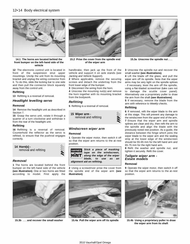
12 The electronic control unit is located infront of the suspension strut uppermountings. Unclip the unit from its mountingbracket and unplug the wiring connector fromit. To do this, slide the locking bar to one sideand then pull the connector block squarelyaway from the control unit.
Refitting13 Refitting is a reversal of removal.
Headlight levelling servo
Removal14 Remove the headlight unit as described inSection 7.15 Grasp the servo unit, rotate it through aquarter of a turn clockwise and withdraw itfrom the rear of the headlight unit.
Refitting16 Refitting is a reversal of removal.Counterhold the reflector as the servo isrefitted, to ensure that the pushrod engagescorrectly.
14 Horn(s) -removal and refitting 2
Removal1 The horns are located behind the frontbumper on the left-hand side of the vehicle(see illustration). One or two horns are fittedaccording to model. First apply the
handbrake, then jack up the front of thevehicle and support it on axle stands (seeJacking and Vehicle Support).2 Where applicable, remove the securingscrews and detach the undertray from thefront lower edge of the bumper.3 Disconnect the wiring from the horn.4 Unscrew the mounting nut(s) and removethe horn together with its mounting bracketfrom the bodywork.
Refitting5 Refitting is a reversal of removal.
15 Wiper arm -removal and refitting 3
Windscreen wiper arm
Removal1 Operate the wiper motor, then switch it offso that the wiper arm returns to the at-restposition.
2 Using a screwdriver prise the cover fromthe spindle end of the wiper arm (seeillustration).
3 Unscrew the spindle nut and recover thesmall washer (see illustrations).4 Lift the blade off the glass, and pull thewiper arm off its spindle. Note that the wiperarms may be very tight on the spindle splines- if necessary, lever the arm off the spindle,using a flat-bladed screwdriver (take care notto damage the scuttle cover panel).Alternatively use a proprietary puller to drawthe arm from the shaft (see illustrations).5 If necessary, remove the blade from thearm with reference to Weekly checks.
Refitting6 If removed, refit the wiper blade to the armat this stage. This will prevent any damage tothe windscreen from the upper end of the arm.7 Ensure that the wiper arm and spindlesplines are clean and dry, then refit the arm tothe spindle and align the blade with thepreviously noted rest position. As a guide, thedistance between the hinge which joins thewiper blade to the wiper arm and the sealingstrip at the lower edge of the windscreenshould be 55-65 mm for the left hand arm and65-75 mm for the right hand arm.8 Refit the washer and spindle nut, andtighten it securely. Refit the cover.
Tailgate wiper arm - Estate models
Removal9 Operate the wiper motor, then switch it offso that the wiper arm returns to the at-restposition.
12•14 Body electrical system
14.1 The horns are located behind thefront bumper on the left-hand side of the
vehicle
15.2 Prise the cover from the spindle endof the wiper arm
15.3a Unscrew the spindle nut . . .
15.3b . . . and recover the small washer 15.4a Pull the wiper arm off its spindle 15.4b Using a proprietary puller to drawthe wiper arm from its shaft
3510 Vauxhall/Opel Omega
Stick a piece of maskingtape on the windscreen,along the edge of the wiperblade, to use as an
alignment aid on refitting.
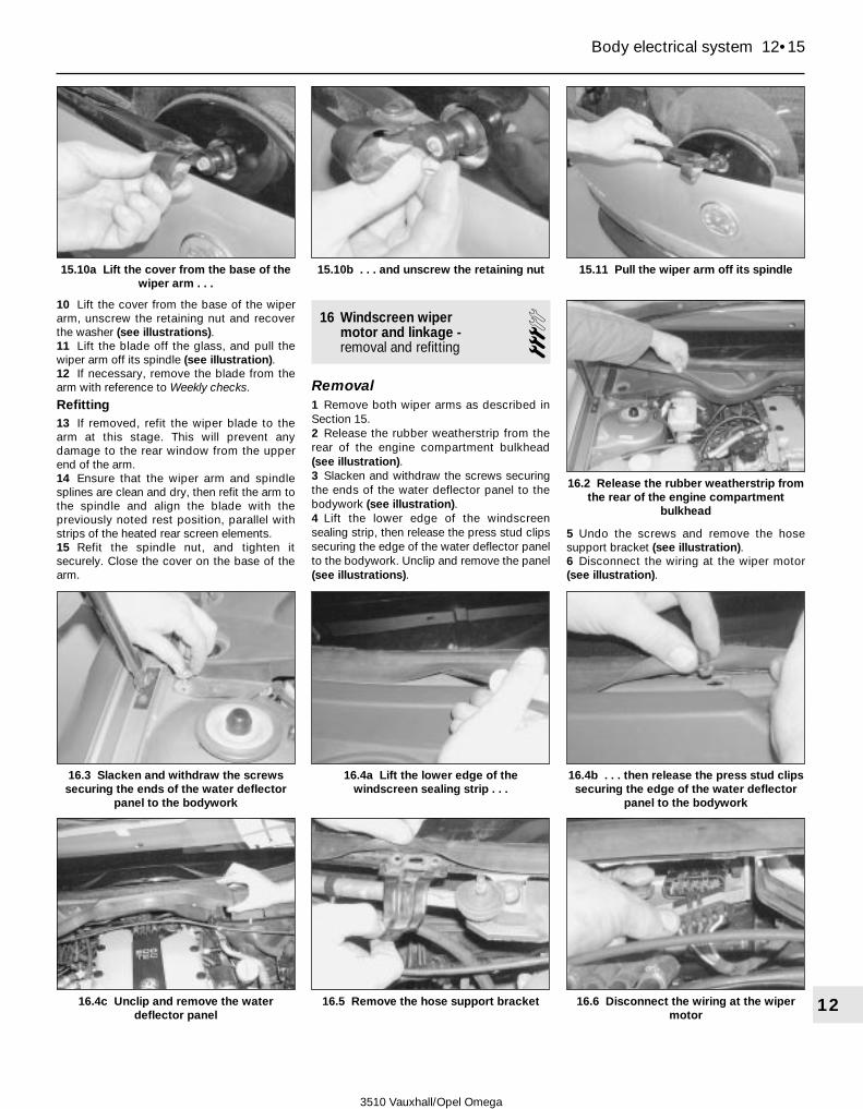
10 Lift the cover from the base of the wiperarm, unscrew the retaining nut and recoverthe washer (see illustrations).11 Lift the blade off the glass, and pull thewiper arm off its spindle (see illustration).12 If necessary, remove the blade from thearm with reference to Weekly checks.
Refitting13 If removed, refit the wiper blade to thearm at this stage. This will prevent anydamage to the rear window from the upperend of the arm.14 Ensure that the wiper arm and spindlesplines are clean and dry, then refit the arm tothe spindle and align the blade with thepreviously noted rest position, parallel withstrips of the heated rear screen elements.15 Refit the spindle nut, and tighten itsecurely. Close the cover on the base of thearm.
16 Windscreen wiper motor and linkage -removal and refitting 3
Removal1 Remove both wiper arms as described inSection 15.2 Release the rubber weatherstrip from therear of the engine compartment bulkhead(see illustration).3 Slacken and withdraw the screws securingthe ends of the water deflector panel to thebodywork (see illustration).4 Lift the lower edge of the windscreensealing strip, then release the press stud clipssecuring the edge of the water deflector panelto the bodywork. Unclip and remove the panel(see illustrations).
5 Undo the screws and remove the hosesupport bracket (see illustration).6 Disconnect the wiring at the wiper motor(see illustration).
Body electrical system 12•15
12
15.10a Lift the cover from the base of thewiper arm . . .
15.10b . . . and unscrew the retaining nut 15.11 Pull the wiper arm off its spindle
16.4c Unclip and remove the waterdeflector panel
16.5 Remove the hose support bracket 16.6 Disconnect the wiring at the wipermotor
16.3 Slacken and withdraw the screwssecuring the ends of the water deflector
panel to the bodywork
16.4b . . . then release the press stud clipssecuring the edge of the water deflector
panel to the bodywork
16.2 Release the rubber weatherstrip fromthe rear of the engine compartment
bulkhead
16.4a Lift the lower edge of thewindscreen sealing strip . . .
3510 Vauxhall/Opel Omega

7 Unscrew the bolts securing the left handend, right hand end and centre of the wipermotor assembly to the scuttle, and withdraw
the assembly from the engine compartment(see illustrations). Note that the centresecuring bolt can only be accessed using anextension bar.8 The motor can be removed from the linkageassembly by prising free the rod from thecrank and unbolting the motor. The remaininglinkage rods can also be dismantled ifnecessary.9 Clean the assembly and examine thespindles and joints for wear and damage.Renew the components as required.
Refitting10 Refitting is a reversal of removal, butlubricate the joints with a little grease beforeassembling them. Note that the grometed lugat the left hand end of the wiper assemblymust engage with the corresponding peg on
the bulkhead bracket (see illustration). Refitthe wiper arms with reference to Section 15.
17 Tailgate wiper motor -removal and refitting 3
Removal1 Remove the wiper arm from the tailgate asdescribed in Section 15.2 Remove the plastic cap from the wiperspindle nut (see illustration).3 Unscrew the nut securing the spindlehousing to the tailgate, and remove thewasher and cover.4 Open the tailgate, then work around theperiphery of the tailgate trim panel andunscrew each of the securing screws. Lift thepanel away from the tailgate (seeillustrations).5 Disconnect the wiper motor wiring at theplug.6 Unscrew the mounting bolts and withdraw thewiper motor while sliding the spindle housingthrough the rubber grommet (see illustration).7 If necessary remove the rubber grommetfrom the tailgate. Examine the grommet forwear and damage and renew it if necessary.
Refitting8 Refitting is a reversal of removal; tighten themounting nut to the specified torque. Refit thewiper arm with reference to Section 15.
18 Windscreen/tailgate/headlightwasher system components -removal and refitting
3Washer fluid reservoir
Removal1 Remove the front bumper as described inChapter 11.2 Undo the screws and remove the frontsection of the left-hand front wheel arch liner.3 The reservoir is mounted behind thebumper inner section; position a containerbeneath the washer fluid pump and reservoirto collect the spilt fluid.
12•16 Body electrical system
16.7a Unscrew the bolts securing the lefthand end . . .
16.7b . . . right hand end . . .
16.7c . . . and centre of the wiper motorassembly to the scuttle. Note that the
centre securing bolt can only be accessedusing an extension bar
16.10 The grometed lug at the left handend of the wiper assembly must engagewith the corresponding peg (arrowed) on
the bulkhead bracket
17.4b . . . and lift the trim panel away fromthe tailgate
17.4a Unscrew each of the securingscrews . . .
17.2 Remove the plastic cap and unscrewthe wiper spindle nut
17.6 Unscrew the mounting bolts(arrowed) and withdraw the wiper motor
3510 Vauxhall/Opel Omega

4 Unbolt the bumper inner section andsupport it away from the front of the vehicle.5 Disconnect the wiring from the top of thepump and position to one side (seeillustration). Where applicable, disconnectthe wiring from the level sensor on the fluidreservoir.6 Disconnect the hose from the pump andallow the fluid to drain into the container (seeillustration).7 On models with a headlight washer system,disconnect the wiring and hose from theadditional pump on the reservoir.8 Disconnect the filler neck from the reservoir(see illustration).9 Release the wiring from the clips on thebumper inner section, then withdraw thebumper inner section together with thereservoir from the front of the vehicle.10 Unscrew the mounting bolts and withdrawthe reservoir from the rear of the bumper innersection (see illustration).
Refitting11 Refitting is a reversal of removal. Fill thereservoir with washer fluid with reference toWeekly checks.
Washer fluid pump
Removal12 Remove the front bumper as described inChapter 11.13 Position a suitable container beneath thewasher fluid pump and reservoir to collect thefluid.14 Disconnect the wiring from the top of thepump and position to one side.
15 Disconnect the hose from the pump andallow the fluid to drain into the container.16 Incline the pump body back towards theengine compartment, then pull to extract itfrom the reservoir grommet (see illustration).17 If necessary, remove the grommet fromthe reservoir.
Refitting18 Refitting is a reversal of removal. Fill thereservoir with washer fluid with reference toWeekly checks.
Windscreen washer nozzle
Removal19 With the bonnet open, disconnect thewiring and supply hose from the bottom of thenozzle.20 Depress the tabs at the rear of the nozzle,then release the nozzle body from the bonnetand remove it upwards.
Refitting21 Refitting is a reversal of removal.
Tailgate washer nozzle - Estatemodels
Removal22 Carefully insert a small screwdriverbetween the nozzle and the rubber seal.Depress the lugs and remove the nozzle fromthe tailgate.23 Disconnect the nozzle from the hose.
Refitting24 Refitting is a reversal of removal.
Headlight washer nozzle
Removal25 Unclip the nozzle head from the highpressure tube.26 Remove the headlight as described inSection 7.27 Release the supply hose from the highpressure tube at the base of the headlightunit.28 Undo the securing screws and detach thehigh pressure tube from the base of theheadlight unit.
Refitting30 Refitting is a reversal of removal.
19 Radio/cassette/CD player -removal and refitting 2
Note: On models with a security-codedradio/cassette player, once the battery hasbeen disconnected, the unit cannot be re-activated until the appropriate security codehas been entered. Do not remove the unitunless the appropriate code is known. Thefollowing information applies to radio/cassetteplayers having standard DIN fixings. Two DINremoval tools will be required for this operation.
Radio/cassette/CD player
Removal1 Using an Allen key, undo the grub screwsfrom the four holes in each corner of the radiofront face (see illustration).
Body electrical system 12•17
12
18.5 Disconnect the wiring from the top ofthe pump and position to one side
18.6 Disconnect the hose from the pumpand allow the fluid to drain into the
container
18.10 Unscrew the mounting bolts andwithdraw the reservoir from the rear of the
bumper inner section
18.16 Pull the pump body to extract it fromthe reservoir grommet (shown with
reservoir removed for clarity)
18.8 Disconnect the filler neck from thereservoir
19.1 Using an Allen key, undo the grubscrews from the four holes in each corner
of the radio
3510 Vauxhall/Opel Omega
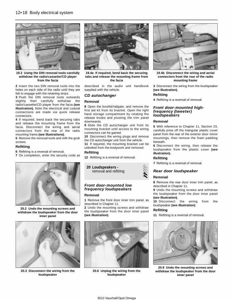
2 Insert the two DIN removal tools into theholes on each side of the radio until they arefelt to engage with the retaining strips.3 Push the DIN removal tools outwardsslightly then carefully withdraw theradio/cassette/CD player from the facia (seeillustration). Note the electrical and coaxialconnections are made via quick releaseconnectors.4 If required, bend back the securing tabsand release the mounting frame from thefacia. Disconnect the wiring and aerialconnectors from the rear of the radiomounting frame (see illustrations).5 Remove the removal tools and refit the grubscrews.
Refitting6 Refitting is a reversal of removal.7 On completion, enter the security code as
described in the audio unit handbooksupplied with the vehicle.
CD autochanger
Removal8 Open the bootlid/tailgate, and remove thefirst aid kit from its bracket. Open the righthand storage compartment by rotating therelease knobs and pivoting the trim paneldownwards.9 Slide the CD autochanger unit from itsmounting bracket until access to the wiringconnectors can be gained.10 Disconnect the wiring plugs and removethe CD autochanger unit from the vehicle.11 If required, the mounting bracket can beunbolted from the bodywork and removed.
Refitting12 Refitting is a reversal of removal.
20 Loudspeakers -removal and refitting 2
Front door-mounted lowfrequency loudspeakers
Removal1 Remove the front door inner trim panel, asdescribed in Chapter 11.2 Undo the mounting screws and withdrawthe loudspeaker from the door inner panel(see illustration).
3 Disconnect the wiring from the loudspeaker(see illustration).
Refitting4 Refitting is a reversal of removal.
Front door-mounted high-frequency (tweeter)loudspeakers
Removal5 With reference to Chapter 11, Section 23,carefully prise off the triangular plastic coverpanel from the rear of the exterior door mirrormountings, then remove the foam paddingbeneath.6 Disconnect the wiring, then release theloudspeaker from the plastic cover (seeillustration).
Refitting7 Refitting is a reversal of removal.
Rear door loudspeaker
Removal8 Remove the rear door inner trim panel, asdescribed in Chapter 11.9 Undo the mounting screws and withdrawthe loudspeaker from the door inner panel(see illustration).10 Disconnect the wiring from theloudspeaker (see illustration).
Refitting11 Refitting is a reversal of removal.
12•18 Body electrical system
19.3 Using the DIN removal tools carefullywithdraw the radio/cassette/CD player
from the facia
19.4a If required, bend back the securingtabs and release the mounting frame from
the facia
19.4b Disconnect the wiring and aerialconnectors from the rear of the radio
mounting frame
20.3 Disconnect the wiring from theloudspeaker
20.2 Undo the mounting screws andwithdraw the loudspeaker from the door
inner panel
20.6 Unplug the wiring from theloudspeaker
20.9 Undo the mounting screws andwithdraw the loudspeaker from the door
inner panel
3510 Vauxhall/Opel Omega

Parcel shelf speakers - Saloon models
Removal12 Remove the rear seat cushions and backrests as described in Chapter 11.13 Where applicable unbolt and remove thecentre three point seat belt with reference toChapter 11.14 Remove the rear headrests, then depressthe locking tabs and remove the headrestguide sleeves from the seat frame.15 Undo the securing screws and remove thecentre arm rest.16 Carefully prise out the press studfasteners and remove the parcel shelf trimpanel from the vehicle.17 Unplug the wiring at the connector, thenslacken and withdraw the screws and removethe speaker from the parcel shelf.
Refitting18 Refitting is a reversal of removal.
21 Radio aerial -removal and refitting 2
Aerial - Saloon models1 The aerial is integral with the rear heatedscreen element.
Aerial - Estate models2 It is recommended that the removal of theaerial is carried by a Vauxhall dealer as theoperation involves the partial removal of theload compartment headlining.
Aerial amplifier - Saloon models
Removal3 Remove the rear seat cushions and backrests as described in Chapter 11.4 Where applicable unbolt and remove thecentre three point seat belt with reference toChapter 11.5 Remove the rear headrests, then depressthe locking tabs and remove the headrestguide sleeves from the seat frame.6 Undo the securing screws and remove thecentre arm rest.
7 Carefully prise out the press stud fastenersand remove the parcel shelf trim panel fromthe vehicle.8 Unscrew the coaxial cable connectors fromthe side of the amplifier unit, the unplug thepower supply wiring connector from the frontof the unit.9 Slacken and withdraw the securing screwsand remove the amplifier unit from the parcelshelf.
Refitting10 Refitting is a reversal of removal.
Aerial amplifier - Estate models
Removal11 Open the tailgate, then work around theperiphery of the tailgate trim panel andunscrew each of the securing screws. Lift thepanel away from the tailgate.12 Unscrew the coaxial cable connectorsfrom the side of the amplifier unit, the unplugthe power supply wiring connector from thefront of the unit.13 Slacken and withdraw the securingscrews and remove the amplifier unit from thetailgate.
Refitting14 Refitting is a reversal of removal.
22 Anti-theft alarm system and engine immobiliser -general information
Note: To avoid triggering the alarm when thebattery removed or disconnected, ensure thatthe negative cable is disconnected not morethan fifteen seconds after the ignition hasbeen switched off. If the alarm has beenactivated, it will reset after 30 seconds, butcan be deactivated during this time byreconnecting the battery and switching on theignition.1 All models have an engine immobiliserwhich effectively prevents the engine frombeing started when the ignition key is in theOFF position or removed from the steeringlock. The system is activated by the ignitionkey and an electronic sensor mounted on thesteering lock. The driver’s door lock barrel isfreewheeling - if an attempt is made toforcefully turn the lock without the correct key,it will just turn within its housing.2 The anti-theft alarm system monitors thedoors, bootlid or tailgate, bonnet, radio, ignition,and on some models the passenger and luggagecompartments. The control unit for the system islocated behind the outer trim panel on the right-hand side of the right-hand footwell. On higherspecification models an ultrasonic sensor islocated at the top of each B-pillar. The anti-theftalarm system horn is located on the bulkhead inthe engine compartment and the power sounderis located beneath the left-hand front wing. OnEstate models, a glass breakage detector is fittedto the luggage compartment rear side windows.
3 To remove the ultrasonic sensor, carefullylever it out of its housing using a screwdriverthen disconnect the wiring.4 To remove the warning horn disconnect thewiring and unscrew the mounting nut.5 To remove the bonnet contact, disconnectthe wiring then detach the contact from thebulkhead.6 To remove the power sounder, disconnectthe battery negative lead, as described inChapter 5A, within 15 seconds of switchingoff the ignition. Remove the wheel arch linerfrom under the left-hand front wing, thendisconnect the wiring and unbolt the bracketand power sounder.7 Refitting of the components is a reversal ofthe removal procedure.8 Any faults with the system should bereferred to a Vauxhall/Opel dealer.
23 Supplementary RestraintSystem - information, precautionsand system de-activation
General information1 A driver’s side airbag is fitted as standardequipment on all models. The airbag is fittedto the steering wheel centre pad. Similarly, apassenger’s side airbag is also fitted asstandard equipment, or as an option,depending on model. On certain later models,side airbags, mounted in the sides of the frontseats, and seat belt tensioners are also fitted.2 The system is armed only when the ignitionis switched on, however, a reserve powersource maintains a power supply to thesystem in the event of a break in the mainelectrical supply. The system is activated by acombination of a g sensor (decelerationsensor), incorporated in the electronic controlunit and air pressure sensors mounted insidethe front doors. Note that the electroniccontrol unit also controls the activation of thefront seat belt tensioners.3 The airbags are inflated by gas generators,which force the bags out from their locationsin the steering wheel, and the passenger’sside facia, where applicable.4 On later models fitted with pyrotechicalseat belt tensioners, actuation is by means ofa gas generator. Some earlier models may befitted with mechanical seat belt tensionerswhich must be deactivated individually.5 In the event of a fault occurring in the airbagsystem (warning light illuminated on theinstrument panel), seek the advice of aVauxhall/Opel dealer.
PrecautionsWarning: The following pre-cautions must be observed whenworking on vehicles equipped
with an airbag system, to prevent thepossibility of personal injury.
General precautions6 The following precautions must be
Body electrical system 12•19
12
20.10 Disconnect the wiring from theloudspeaker
3510 Vauxhall/Opel Omega

observed when carrying out work on a vehicleequipped with an airbag.a) Do not disconnect the battery with the
engine running.b) Before carrying out any work in the vicinity
of the airbag, removal of any of the airbagcomponents, or any welding work on thevehicle, de-activate the system asdescribed in the following sub-Section.
c) Do not attempt to test any of the airbagsystem circuits using test meters or anyother test equipment.
d) If the airbag warning light comes on, orany fault in the system is suspected,consult a Vauxhall/Opel dealer withoutdelay. Do not attempt to carry out faultdiagnosis, or any dismantling of thecomponents.
Precautions to be taken whenhandling an airbaga) Transport the airbag by itself, bag
upward.b) Do not put your arms around the airbag.c) Carry the airbag close to the body, bag
outward.d) Do not drop the airbag or expose it to
impacts.e) Do not attempt to dismantle the airbag
unit.f) Do not connect any form of electrical
equipment to any part of the airbagcircuit.
g) Do not allow any solvents or cleaningagents to contact the airbag assembly.The unit must be cleaned using only adamp cloth.
Precautions to be taken when storingan airbag unita) Store the unit in a cupboard with the
airbag upward.b) Do not expose the airbag to temperatures
above 90ºC.c) Do not expose the airbag to flames.d) Do not attempt to dispose of the airbag -
consult a Vauxhall/Opel dealer.e) Never refit an airbag which is known to be
faulty or damaged.
De-activation of theSupplementary RestraintSystem (SRS) airbag system7 The system must be de-activated asfollows, before carrying out any work on theairbag components or surrounding area.a) Switch off the ignition.b) Remove the ignition key.c) Switch off all electrical equipment.d) Disconnect the battery negative lead (see
Chapter 5A).e) Insulate the battery negative terminal and
the end of the battery negative lead toprevent any possibility of contact.
f) Wait for at least one minute beforecarrying out any further work. This willallow the system capacitor to discharge.
Deactivation of mechanical seatbelt tensionersNote: This section only applies to modelsfitted with mechanical seat belt tensioners. Todeactivate the pyrotechnical seat belttensioners fitted to later models, follow theSRS deactivation procedure detailed in theprevious sub-section.8 Remove the seat runner trim panels asdescribed at the beginning of Chapter 11,Section 27.9 The seat belt tensioner unit is mountedadjacent to the seat runner. Remove the seatbelt tensioner locking tool from its storageposition and insert it fully into the grooveprovided at the end of the tensioner unit. Thiswill prevent the tensioner mechanism fromrecoiling if it is accidentally activated.10 On completion, remove the locking tooland refit the seat runner trim panels beforebringing the vehicle back service.
24 Supplementary RestraintSystem (SRS) components -removal and refitting
4Driver’s side airbag unit
Warning: Refer to the precautionsgiven in Section 23 beforeattempting to carry out work on
the airbag components.
Removal - models up to 19961 The airbag unit is an integral part of thesteering wheel centre pad.2 De-activate the airbag system as describedin Section 23.3 Set the front wheels in the straight-aheadposition, then turn the steering wheel onequarter turn to the right. Slacken and removethe left hand airbag securing screw.4 Turn the steering wheel back to the straightahead position, then turn it one quarter turn tothe left. Slacken and remove the right handairbag securing screw.3 Return the steering wheel to the straight-ahead position, then lock the column inposition after removing the ignition key.4 Disconnect the wiring from the airbag.Position the airbag in a safe place where itcannot be tampered with, making sure thatthe padded side is facing upwards.
Removal - models from 1996 onwards5 The airbag unit is an integral part of thesteering wheel centre pad.6 De-activate the airbag system as describedin Section 23.7 Set the front wheels in the straight-aheadposition, then lock the column in position afterremoving the ignition key.8 Unscrew and remove the two screws fromthe rear of the steering wheel and carefully liftthe airbag/horn-push from the steering wheel(see illustrations).9 Disconnect the wiring from the airbag (seeillustration). Observe the handling andstorage precautions given in Section 23.
Refitting10 Refitting is a reversal of removal, butmake sure that the wiring connector issecurely reconnected and tighten theretaining screws to the specified torque.
Passenger’s side airbag unitWarning: Refer to the precautionsgiven in Section 23 beforeattempting to carry out work on
the airbag components.
Removal11 De-activate the airbag system asdescribed in Section 23.12 Remove the glovebox as described inChapter 11.13 Unclip the cover panel from the left handfacia end section.14 Unclip the bulb holder from the rear of theair vent housing and position it to one side.
12•20 Body electrical system
24.8a Unscrew and remove the two screwsfrom the rear of the steering wheel . . .
24.8b . . . and carefully lift the airbag/horn-push from the steering wheel
24.9 Disconnect the wiring from the airbag
3510 Vauxhall/Opel Omega

15 Slacken and withdraw the securingscrews then detach the nozzle from the lefthand air vent housing.16 Undo the securing screws and remove theleft hand vent housing from the facia.17 Unscrew the lower mounting screws anddetach the lower edge of the hinged airbagcover from the facia.18 Using a long extension bar and a pair oflong nosed pliers, slacken and withdraw theairbag cover hinge bolt (see illustrations).19 Remove the hinged cover to expose theairbag unit (see illustration).20 Slacken and remove the airbag unitsecuring bolts, then withdraw the unit from itsmounting bracket slightly (see illustration).21 Unplug the wiring connector from theairbag, then remove the air bag unit from thevehicle (see illustration). Observe the handlingand storage precautions given in Section 23.
Refitting22 Refitting is a reversal of removal, but makesure that the wiring connector is securelyreconnected. Use new airbag securing boltsand tighten them to the specified torque.
Side airbag unitWarning: Refer to the precautionsgiven in Section 23 beforeattempting to carry out work on
the airbag components.
Removal23 Removal of the side airbags involvespartially dismantling the seat upholstery; it istherefore recommended that this work iscarried out by a Vauxhall dealer.
Airbag contact unit (on steering column)
Removal24 Remove the driver’s airbag unit asdescribed earlier in this Section.25 Remove the steering wheel as describedin Chapter 10.26 Remove the steering column shrouds byunscrewing the tilt steering lever, thenremoving the screws from the end face andthe lower shroud panel. Recover the ignitionkey position indicator from the ignition switch.27 Using a small screwdriver release thelocking plate, then disconnect the wiring plug(see illustration).28 Release the four rear clips and remove thecontact unit from the top of the column (seeillustrations). Note: Make sure that thecontact unit halves remain in their centralposition with the arrows aligned at the bottom.
If necessary, apply tape to the halves to holdthem. Note that on later models, as the unit isremoved from the steering column, an integrallocking catch engages, preventingunintentional rotation of the two halves of thecontact unit.
Refitting29 Before refitting the contact unit, if thecentre position has been lost or if a new unit isbeing fitted, determine the centre position asfollows. Depress the detent on top of the unitand carefully turn the centre part of the unitanti-clockwise until resistance is felt. Now turnit 2.5 turns clockwise and align the arrows onthe centre part and outer edge (seeillustration).30 If a new unit is fitted, first remove thetransport clip.31 Locate the contact unit on the top of thesteering column making sure that the guide
Body electrical system 12•21
12
24.18a Using a long extension bar and apair of long nosed pliers, slacken . . .
24.18b . . . and withdraw the airbag coverhinge bolt
24.19 Remove the hinged cover to exposethe airbag unit
24.27 Release the locking plate, thendisconnect the contact unit wiring plug
24.28a Release the rear clips . . . 24.28b . . . and remove the contact unitfrom the top of the column
3510 Vauxhall/Opel Omega
24.21 Unplug the wiring connector fromthe airbag
24.20 Slacken and remove the airbag unitsecuring bolts

pins locate in the holes provided. Press theunit in until the clips engage. Note: The clipsmust not be damaged in any way. If they are,the unit must be renewed.32 Reconnect the wiring while depressingthe slider.33 Refit the ignition key position indicator,then refit the steering column shrouds andtighten the securing screws. Refit and tightenthe tilt steering lever.34 Refit the steering wheel as described inChapter 10.35 Refit the driver’s airbag unit as describedearlier.
Electronic control unit
Removal36 De-activate the airbag system asdescribed in Section 23.37 Remove the centre console as describedin Chapter 11.38 Disconnect the wiring from the controlunit, then unscrew the mounting nuts andremove the unit from inside the vehicle.
Refitting39 Refitting is a reversal of removal buttighten the mounting nuts to the specifiedtorque.
Door-mounted side impactsensor
Removal40 De-activate the airbag system asdescribed in Section 23.41 Remove the front door inner trim panel asdescribed in Chapter 11.42 Pull back the water membrane for accessto the sensor.
Warning: The door side impactsensors are air pressure sensitiveand will only operate correctly if
the protective plastic door membrane isrefitted correctly; bear this in mind whenremoving the membrane from the door.43 Unscrew the securing screws and removethe sensor from its mounting bracket. Unplugthe wiring from the sensor at the connector(see illustrations).
44 If required the sensor bracket can beremoved by drilling out the securing rivets.New pop rivets will then be needed to securethe bracket tot he door on refitting.
Refitting45 Refitting is a reversal of removal. Ensurethat the plastic door membrane is securelyrefitted. The sealing strip around the edge ofthe membrane must adhere to the doorwithout gaps, to form an airtight seal. If themembrane was cut or torn during its removal,ensure that the loose edges are stuck to thedoor using a suitable adhesive/sealant. If youare in doubt about the integrity of the seal, it’sbest to renew the membrane and sealing stripentirely.
25 Cruise control systemcomponents - removal and refitting
3Actuator cable
Removal1 Disconnect the accelerator cable from thethrottle disc lever balljoint, with reference toChapter 4A.2 Remove the circlip, then disconnect thecruise control actuator cable from the throttledisc lever balljoint.3 Depress the locking tabs and release theactuator cable guide tube from the mountingbracket.4 At the actuator unit, turn the cable guidetube union through one quarter of a turnanticlockwise to release it. Unhook the cablenipple from the actuator and remove it fromthe vehicle.
Refitting5 Refitting is a reversal of removal.
Actuator/control unit
Removal6 The actuator/control unit is located on theright hand side of the engine compartment.
7 Disconnect the actuator cable from the unitas described in the previous sub-section.8 Unplug the wiring from the unit at themultiway connector.9 Unscrew the three nuts and remove the unitfrom the vehicle.
Refitting10 Refitting is a reversal of removal.
Clutch pedal switch
Removal11 Working in the drivers foot well, releasethe securing clips and remove the trim panelfrom the space above the foot pedals.12 Remove the securing screws, detach thefoot well vent moulded air ducting from the airdistributor unit and remove it from the footwell.13 Push the clutch pedal forwards, then pullout the actuator pin and locking sleeve fromthe switch body.14 Depress the locking tabs and release theswitch from its mounting bracket. Unplug thewiring at the connector and remove the switchfrom the vehicle.
Refitting15 Pull the switch actuator pin out to its endstop. Similarly, pull the switch locking collarout to the end of its travel before fitting.16 Depress the clutch pedal, the fit theswitch into its mounting bracket until thelocking tabs engage.17 Press the locking collar fully into theswitch body to lock the switch in position.18 Ensure that the switch actuator is stillpulled put to its end stop, then slowly releasethe clutch pedal until it contacts the switchactuator pin. The switch will self-adjust as theclutch pedal reaches its rest position.19 Refit the remainder of the componentsremoved for access.
Steering column controlswitches20 The cruise control steering columnswitches are integral with the directionindicator switch assembly; refer to theinformation given in Section 4.
12•22 Body electrical system
24.29 Airbag contact unit alignmentmarkings (arrowed) - refer to text
24.43a Unscrew the securing screws andremove the sensor from its mounting
bracket
24.43b Unplug the wiring from the sensorat the connector
3510 Vauxhall/Opel Omega

26 Wiring diagrams -general information
The wiring diagrams are of the current flowtype, each circuit being shown in the simplestpossible fashion. Note that since the diagramswere originally written in German (to the DIN
standard), all wire colours and abbreviationsused on the diagrams themselves are inGerman. Refer to the information given belowfor clarification.
The bottom line of the diagram representsthe “earth” or negative connection; thenumbers below this line are track numbers,enabling circuits and components to belocated using the key.
The lines at the top of the diagram represent
“live feed” or positive connection points. Theline marked “30” is live at all times. The linemarked “15” is live only when the ignition isswitched on.
Numbers on the diagram that are framed insquare boxes at the end of a wire show thetrack reference number in which that wire iscontinued. At the point indicated will beanother framed number referring back to thecircuit just left.
Body electrical system 12•23
12
3510 Vauxhall/Opel Omega
Explanations of abbreviations used in wiring diagramsAB Air bagABS Anti-lock braking systemAC Air conditioningASP Outside mirrorAT Automatic transmissionAZV Trailer hitchCC Check controlCD CD changerCRC Cruise controlD DieselDS Anti-theft deviceDT TurbodieselDTH Turbodiesel X 20 DTHDWA Anti-theft warning systemDZM TachometerECC Electronic Climate ControlEKP Fuel pumpEMP RadioFH Electric windowsFIN FinlandGB Great BritainHS Heated rear windowHSF Glove compartmentHKL Power steeringHRL Luggage compartment lightHZG HeatingID Info-Display (TID/MID)IMO ImmobiliserINS Instrument panelIRL Courtesy lightsIRLT Interior lightJ JapanKAT Catalytic converter
KBS Wiring harnessKW EstateLED Light-emitting diodeLHD Left-hand driveMID Multi Info-DisplayMT Manual transmissionN NorwayNB NotchbackNS Front foglightsNSL Rear foglightsOEL Oil level/pressure check systemPBSL Park/brake lockout (automatic transmission)P/N Park/Neutral (automatic transmission)RFS Reversing lightsRHD Right-hand driveS SwedenSA Saudi ArabiaSD SunroofSH Heated seatsSM Engine control unitSRA Headlight washers and wipersTC Traction ControlTD TurbodieselTEL TelephoneTFL Daytime driving lightsTID Triple Info DisplayTKS Door contact switchWEG Odometer frequency/roadspeed sensorWD Washer nozzleWS Warning buzzerZIG Cigarette lighterZV Central locking
Colour codes
BL BlueHBL Light blueBR BrownGE YellowGR GreyGN Green
RT RedWS WhiteSW BlackLI LilacVI Violet
Wiring identification
Note: Not all items shown are fitted to all models.
Example: GE WS 1.5GE - Wire basic colourWS - Wire tracer colour1.5 - Wire cross-section in mm2

12•24 Wiring diagrams
3510 Vauxhall/Opel Omega
Index of circuits 100 to 1199 - early modelsLocation of applicable circuits TrackAir conditioning 700Airbag 528Alternator 115Anti-lock Braking System 122Anti-theft device 904Anti-theft warning system 928Automatic transmission 214Battery 101Brake light 461Car level control 542CD changer 1070Central locking 900Check control 820Cigarette lighter 555Coolant pump (S, N, FIN) 120Cruise control 588Daytime driving light 400Door contact switch 48520SE engine - MOTRONIC 1.5.4 155X20SE engine - MOTRONIC 1.5.4 155X20XEV engine - SIMTEC 56.1 353X25XE engine - MOTRONIC 2.8.1 249X30XE engine - MOTRONIC 2.8.1 24925DT engine - Turbodiesel 300Fanfare 523Front/rear door light 493Front fog lights 439Front door light 966Fuel pump 197Glove compartment light 561Hazard warning lights 466Headlight washer 519Headlight range control 429Heated rear screen 619Heated washer nozzles 506Heater nozzle lights 563Heating 1100
Location of applicable circuits TrackHigh beam 443Immobiliser 952Info display (MID/TID) 840Instrument 865Interior light 483Light switch 415Licence plate light 419Low beam 428Luggage compartment light 481Memory - driver’s seat and mirrors 659Outside mirror 600Parking lights 410Power steering 200Radiator fan (with AC) 731Radiator fan (without AC) 1111Radio with sound processor 1034Radio 1001Rear screen wiper 511Rear door fan 960Rear fog lights 449Recirculating air 1154Reversing lights 538Seat heating 568Seat adjustment 1179Sliding roof 800Sound processor 1034Starter 105Sunscreen 810Tail light 412Telephone 1082Traction control 122Trailer socket 411Turn signal light 466Vanity mirror 815Warning buzzer/light switch 422Window winders 967Windscreen wiper 500
No DescriptionE1 Side light - leftE2 Tail light - leftE3 Number plate lightE4 Side light - rightE5 Tail light - rightE7 Headlight main beam - leftE8 Headlight main beam - rightE9 Headlight dipped beam - leftE10 Headlight dipped beam - rightE11 Instrument illumination lightsE13 Luggage compartment lightE15 Glovebox lightE16 Cigarette lighter illumination lightE17 Reversing light - leftE18 Reversing light - rightE19 Heated rear windowE20 Front foglight - leftE21 Front foglight - rightE24 Rear foglight - leftE25 Driver’s seat heaterE27 Courtesy light - rear leftE28 Courtesy light - rear rightE30 Passenger front seat heaterE33 Ashtray light
No DescriptionE37 Left hand vanity mirrorE39 Rear foglight - rightE40 Right hand vanity mirrorE41 Courtesy lightE47 Left rear seat heaterE48 Right rear seat heaterE50 Kerb light - left front doorE51 Kerb light - right front doorE52 Kerb light - left rear doorE53 Kerb light - right rear doorE54 Cigarette lighter light, rearE55 Heating nozzle operating handle lightE57 Heating nozzle light, leftE58 Heating nozzle light, rightE59 Heating nozzle light, rearF1 on FusesG1 BatteryG2 AlternatorH1 Radio/cassette playerH2 HornH3 Direction indicator warning lightH4 Oil pressure warning lightH5 Brake fluid level warning lightH7 Alternator charge warning light
No DescriptionH8 Headlight main beam warning lightH9 Brake light - leftH10 Brake light - rightH11 Direction indicator light - front leftH12 Direction indicator light - rear leftH13 Direction indicator light - front rightH14 Direction indicator light - rear rightH15 Fuel level warning lightH16 Glow plug warning light (Diesel models)H17 Trailer direction indicator warning lightH18 HornH22 Rear foglight warning lightH23 Airbag warning lightH25 Door mirror heating warning lightH26 ABS warning lightH30 Engine fault warning lightH33 Direction indicator side repeater light
- leftH34 Direction indicator side repeater light
- rightH36 Brake light - middleH37 Loudspeaker - left front doorH38 Loudspeaker - right front doorH39 Loudspeaker - left rear door
Key to wiring diagrams for early models

Wiring diagrams 12•25
12
3510 Vauxhall/Opel Omega
No DescriptionH40 Loudspeaker - right rear doorH42 Automatic transmission warning lightH47 Anti-theft alarm hornH48 HornH51 Traction control warning lightH52 Tweeter - left front doorH53 Tweeter - right front doorH54 TelephoneH55 HandsetH56 MicrophoneH57 Tweeter - left rear doorH58 Tweeter - right rear doorH61 Sub-woofer - left rearH62 Sub-woofer - right rearH63 Immobiliser warning lightK3 Relay - starter motor (anti-theft alarm)K6 Relay - air conditioningK7 Relay - air conditioning blowerK8 Relay - intermittent windscreen wipeK10 Relay - direction indicator/hazard
warning flashersK12 Relay - secondary air intakeK13 Relay - park/neutral signal (AT)K14 Relay - cruise controlK16 Relay - reconveying pumpK17 Relay - polarity protectionK19 Relay - car level controlK21 Sensor - car level controlK22 Relay - air conditioning coolant pumpK25 Relay - glow plugs (Diesel models)K26 Relay - blowerK28 Relay - blowerK30 Relay - intermittent rear wiper delayK31 Airbag control unitK35 Relay - time delay, heated mirror and
rear windowK37 Central locking control unitK41 Power steering control unitK42 Relay - polary protectionK43 Relay - injectorsK44 Relay - fuel pumpK48 Relay - blowerK49 Relay - blowerK51 Relay - cooling fanK52 Relay - blowerK59 Relay - daytime running lightsK60 Relay - air conditioning compressorK61 Engine control unit (Motronic)K63 Relay - hornK64 Relay - air conditioning blowerK65 Relay - left rear seat heaterK66 Relay - right rear seat heaterK67 Relay - cooling fanK69 Simtec 56 control unitK70 Turbodiesel control unitK73 Relay - headlight main beam relayK80 Relay - fuel filter heater (Diesel models)K85 Automatic transmission control unitK87 Relay - auxiliary cooling fanK88 Catalytic converter temp. control unitK94 Anti-theft alarm control unitK96 Relay - cooling fanK97 Relay - headlight washer pump time
delayK101 Relay - electric mirror parking positionK102 Parking brake control unit (automatic
transmission)
No DescriptionK117 Immobiliser control unitL2 Ignition coilM1 Starter motorM2 Windscreen wiper motorM3 Heater blower motorM4 Radiator cooling fan motorM8 Rear window wiper motorM10 Air conditioning blower motorM11 Cooling fan motorM18 Central locking motor - driver’s doorM19 Central locking motor - left rear doorM20 Central locking motor - right rear doorM21 Fuel pumpM22 Compressor, car level controlM24 Headlight washer pumpM27 Secondary air intake pumpM28 Blower motorM29 Interior mirror motorM30 Door mirror assembly - driver’s doorM30.1 Mirror adjustment motorM30.2 Mirror heatingM30.4 Mirror memory potentiometerM31 Door mirror assembly - passenger doorM31.1 Mirror adjustment motorM31.2 Mirror heatingM31.4 Mirror memory potentiometerM32 Central locking motor - passenger
doorM33 Idle speed adjuster/idle air control
stepper motorM34 Sunvisor motorM35 Cooling fan motorM37 Central locking motor - boot
lid/tailgateM39 Headlight aim adjuster motor - left sideM40 Headlight aim adjuster motor - right
sideM41 Central locking motor - fuel fillerM47 Electric window motor - front leftM48 Electric window motor - front rightM49 Electric window motor - rear leftM50 Electric window motor - rear rightM54 Coolant pump timing controlM55 Windscreen and rear window washer
pumpM57 Coolant pumpM61 Sunroof assemblyM67 Blower motor - left rear doorM68 Blower motor - right rear doorM72 Seat adjustment assembly, driverM72.1 Front seat height motorM72.2 Rear seat height motorM72.3 Forwards/backwards seat adjustment
motorM72.4 Seat backrest motorM73 Seat adjustment assembly, driverM73.1 Front seat height motorM73.2 Rear seat height motorM73.3 Forwards/backwards seat adjustment
motorM73.4 Seat backrest motorM74 Seat adjustment assembly,
passengerM74.1 Front seat height motorM74.2 Rear seat height motorM74.3 Forwards/backwards seat adjustment
motor
No DescriptionM74.4 Seat backrest motorP1 Fuel gaugeP2 Coolant temperature gaugeP4 Fuel level sender unitP5 Coolant temperature gauge senderP7 TachometerP13 Trip computer outside air temperature
sensorP17 ABS wheel sensor - front leftP18 ABS wheel sensor - front rightP19 ABS wheel sensor - rear leftP20 ABS wheel sensor - rear rightP25 Bulb failure sensorP27 Brake pad wear sensor - front leftP28 Brake pad wear sensor - front rightP29 Air intake temperature sensorP30 Coolant temperature sensorP32 Oxygen sensor - heatedP34 Throttle position
sensor/potentiometerP35 Crankshaft speed/position sensorP36 Oxygen sensor - heatedP37 Telephone aerialP39 Trailer bulb failure sensorP43 Electronic speedometerP44 Air mass meterP46 Knock sensorP47 Camshaft sensorP48 Automatic transmission output speed
sensorP50 Catalytic converter temperature
sensorP51 Crankshaft sensorP53 Anti-theft alarm sensor - left sideP54 Anti-theft alarm sensor - right sideP56 Knock sensorP58 Left rear window breakage sensor
(Estate)P59 Right rear window breakage sensor
(Estate)P63 Receiver, remote controlP64 Catalytic converter temperature
sensorP65 Load/pressure sensorP66 Needle movement sensorP67 Pedal position sensorP68 Injection pump actuatorR3 Cigarette lighterR5 Glow plugs (Diesel models)R13 Heated windscreen washer nozzle -
leftR14 Heated windscreen washer nozzle -
rightR17 Cigarette lighter, rearR19 Cooling fan motor resistorS1 Ignition switchS2 Lighting switch asssemblyS2.1 Lighting switchS2.2 Courtesy light switchS2.3 Instrument illumination light dimmerS2.4 Warning buzzerS2.5 Headlamp levellingS2.6 Front fog lights switchS2.7 Rear fog lights switchS3 Heater blower switchS4 Heated rear window and mirror switchS5 Direction indicator switch assembly

12•26 Wiring diagrams
3510 Vauxhall/Opel Omega
No DescriptionS5.2 Dipped beam switchS5.3 Direction indicator switchS5.4 Sidelight switchS7 Reversing light switchS8 Brake light switchS9 Windscreen wiper switch assemblyS9.2 Windscreen wiper interval switchS9.5 Rear window washer/wiper switchS11 Brake fluid level warning sensorS13 Handbrake-on warning switchS15 Luggage compartment light switchS17 Passenger door courtesy light switchS18 Glove box light switchS20 Pressure switch assemblyS20.1 Low pressure compressor switchS20.2 High pressure compressor switchS20.3 High pressure compressor switchS24 Air conditioning blower motor switchS29 Cooling fan switchS30 Driver’s seat heater switchS31 Rear door courtesy light switch - leftS32 Rear door courtesy light switch - rightS33 Traction control switchS37 Driver’s door electric window switch
assemblyS37.1 Electric window switch - front leftS37.2 Electric window switch - front rightS37.3 Electric window switch - rear leftS37.4 Electric window switch - rear rightS37.5 Electric window safety cut-out switchS37.7 Electric window automatic controlS39 Electric window switch - rear left doorS40 Drivers seat adjustment assembly
(with memory)S41 Central locking switch - driver’s doorS42 Central locking switch - passenger
doorS43 Cruise control switchS45 Cruise control clutch switchS47 Driver’s door courtesy light switchS49 Sunvisor switchS52 Hazard warning light switchS55 Passenger seat heater switchS56 Rear door blower switch
No DescriptionS58 Temperature switch - relay boxS59 Fog light switch, trailer socketS63 Switch assembly - MIDS63.1 Trip computer function reset switchS63.2 Trip computer clock hours
adjustment switchS64 Horn switchS68 Door mirror switch assemblyS68.1 Door mirror adjustment switchS68.3 Door mirror left/right selector switchS68.4 Door mirror parking position switchS82 Washer pump switchS86 Passenger compartment switch (DWA)S88 Cooling fan switchS92 Boot lock switch (DWA)S93 Coolant level sensorS95 Oil level sensorS96 Left rear seat heater switchS97 Right rear seat heater switchS101 Air conditioning compressor switchS102 Air conditioning circulation switchS104 Automatic transmission kickdown
switchS105 Automatic transmission “Winter”
mode buttonS106 Automatic transmission
“Economy/Sport” mode buttonS109 Revolution acceleration switch
(Motronic)S118 Automatic transmission switchS119 Air conditioning refrigerant
temperature switchS120 Anti-theft alarm bonnet switchS128 Air conditioning refrigerant
temperature cooling switchU4 ABS hydraulic modulator assemblyU4.1 ABS hydraulic pump relayU4.2 ABS solenoid valves relayU4.3 ABS hydraulic pumpU4.5 ABS solenoid valve - front leftU4.6 ABS solenoid valve - front rightU4.7 ABS solenoid valve - rear leftU4.8 ABS/TC control unitU4.9 Solenoid valve plug
No DescriptionU6 LCD instrumentsU10 Automatic transmissionU10.1 Solenoid - converter lock-up controlU10.2 Solenoid - main fluid pressure controlU12 Filter heating assembly (Diesel models)U12.1 Temperature switch (Diesel models)U12.2 Heating resistor (Diesel models)U13 Automatic transmissionU13.1 Solenoid - 2/3 shift upU13.2 Solenoid - 1/2 and 3/4 shift upU13.3 Solenoid - converter lock-up controlU13.4 Solenoid - oil temperature sensorU15 Display - TIDU16 Display - MIDU18 Aerial amplifier - heated rear windowU20 Airbag contact unit assemblyU21 Airbag unit assembly, driverU21.1 Airbag unit squibU22 Airbag unit assembly, passengerU22.1 Airbag unit squibU23 Sound processorU24 CD-changerV8 Air conditioning compressor diodeY1 Air conditioning compressor clutchY5 Fuel solenoid valve (Diesel models)Y7 Fuel injectorsY9 Solenoid - car level controlY14 Air conditioning coolant valveY15 Solenoid - secondary air intakeY18 Solenoid - exhaust gas recirculationY19 Solenoid - inlet manifoldY20 Solenoid - injection regulationY25 Power steering solenoid valveY34 Fuel tank vent valveY35 Air conditioning circulation solenoid
valveY46 Solenoid - inlet manifoldY47 Parking brake lock lifting magnet
(automatic transmission)X13 Diagnostic equipment connectorX15 Octane coding plugX54 Ignition coding plugX1-on Wiring connectors
Key to wiring diagrams for early models (continued)
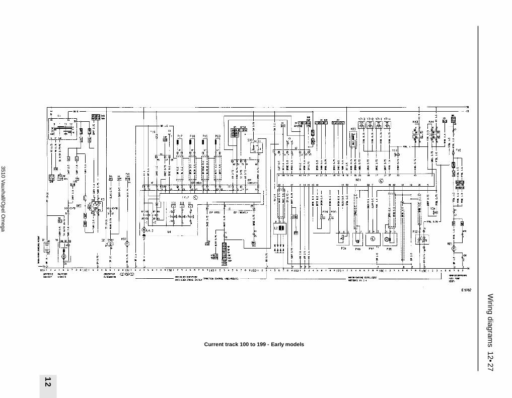
Wiring d
iagrams 12•27
12
3510 Vauxhall/O
pel O
mega
Current track 100 to 199 - Early models
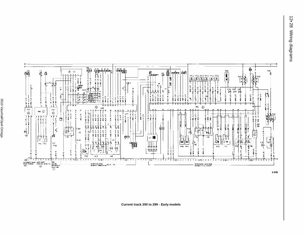
12•28W
iring diagram
s
3510 Vauxhall/O
pel O
mega
Current track 200 to 299 - Early models

Wiring d
iagrams 12•29
12
3510 Vauxhall/O
pel O
mega
Current track 300 to 399 - Early models

12•30W
iring diagram
s
3510 Vauxhall/O
pel O
mega
Current track 400 to 499 - Early models

Wiring d
iagrams 12•31
12
3510 Vauxhall/O
pel O
mega
Current track 500 to 599 - Early models
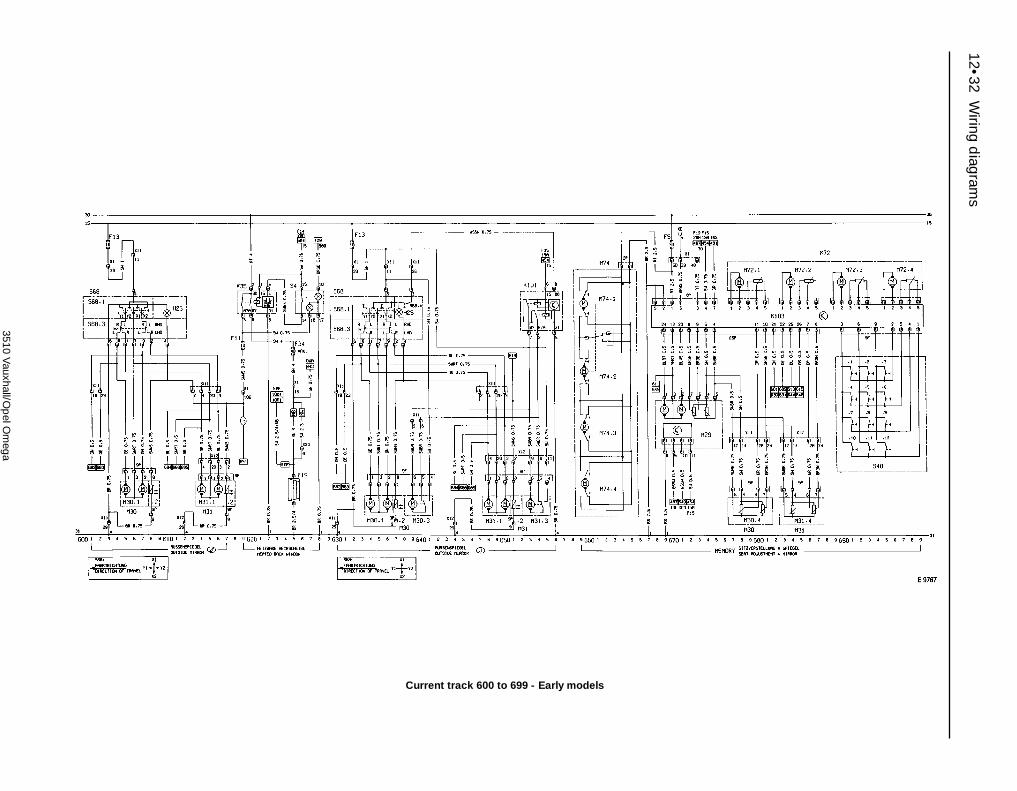
12•32W
iring diagram
s
3510 Vauxhall/O
pel O
mega
Current track 600 to 699 - Early models

Wiring d
iagrams 12•33
12
3510 Vauxhall/O
pel O
mega
Current track 700 to 799 - Early models

12•34W
iring diagram
s
3510 Vauxhall/O
pel O
mega
Current track 800 to 899 - Early models

Wiring d
iagrams 12•35
12
3510 Vauxhall/O
pel O
mega
Current track 900 to 999 - Early models

12•36W
iring diagram
s
3510 Vauxhall/O
pel O
mega
Current track 1000 to 1099 - Early models

Wiring d
iagrams 12•37
12
3510 Vauxhall/O
pel O
mega
Current track 1100 to 1199 - Early models

12•38 Wiring diagrams
3510 Vauxhall/Opel Omega
Index of circuits 100 to 1699 - later modelsLocation of applicable circuits TrackAir conditioning AC/ECC X 20 DTH 1264Air conditioning, not X 20 DTH 700Airbag 1313Airbag, side airbag 1313Alternator 112Anti-lock Braking System 1406Anti-theft device 900Anti-theft warning system 900Automatic transmission 208Auxiliary heater 1651Battery 101Belt tensioner 1313Brake light 411Car level control 537CD changer 1070Central locking 900Check control 820Cigarette lighter 555Coolant heating, auxiliary 1651Coolant pump (S, N, FIN) without A/C 1109Coolant pump (S, N, FIN) with A/C 748Cruise control 524Daytime driving light 1506Door contact switch 460Electronic climate control (ECC) 1200Engine - 20 SE MOTRONIC 1455Engine - X 20 DTH 1601Engine - X 20 SE MOTRONIC 1455Engine - X 20 XEV SIMTEC 353Engine - X 25 DT Turbodiesel 301Engine - X 25 XE MOTRONIC 243Engine - X 30 XE MOTRONIC 243Fanfare 1300Front door light 467Front fog light 1552Fuel pump 1497Fuses 102Glove compartment light 563Hazard warning lights 424Headlight range control (xenon lights) 1578Headlight range control 1535Headlight washer 519Heated rear screen 619Heated washer nozzles 506Heater nozzle lights 563Heating 1100Heating, coolant, auxiliary 1651High beam 1556Immobiliser 1159
Location of applicable circuits TrackInfo display (MID/TID) 840Instrument 865Interior light 471Light switch 1520Licence plate light 1525Low beam 1533Low beam (LWR) 1533Low beam (xenon) 1545Luggage compartment light 447Memory - driver’s seat and mirrors 659Outside mirror 601Park/brake lockout 201Parking light 1510Power sounder 956Power steering 1443Pre-fuses 114Radiator fan (AC/ECC) 731Radiator fan (without AC) 1111Radiator fan X 20 DTH 1673Radiator fan X 20 DTH (AC) 1350Radio 1001Radio remote control 1338Radio with sound processor 1034Rear door fan 960Rear door light 472Rear fog light 1568Rear screen wiper 511Recirculating air 1154Reversing lights 485Seat adjustment & mirror with memory 659Seat adjustment without memory 1179Seat heating 568Side airbag 1313Sound processor 1034Starter 105Sun roller 810Sun roof 800Tail light 1513Telephone 1082Traction control 1406Trailer socket 401/1573Turn signal 424Vanity mirror 815Warning buzzer/light switch 1525Warning buzzer, ignition key 587Window winders 967Windscreen wiper 500Xenon lights 1544
No DescriptionE1 Side light - leftE2 Tail light - leftE3 Number plate lightE4 Side light - rightE5 Tail light - rightE7 Headlight main beam - leftE8 Headlight main beam - rightE9 Headlight dipped beam - leftE10 Headlight dipped beam - rightE11 Instrument illumination lightsE13 Luggage compartment lightE15 Glovebox lightE16 Cigarette lighter illumination light
No DescriptionE17 Reversing light - leftE18 Reversing light - rightE19 Heated rear windowE20 Front foglight - leftE21 Front foglight - rightE24 Rear foglight - leftE25 Driver’s seat heaterE27 Courtesy light - rear leftE28 Courtesy light - rear rightE30 Passenger front seat heaterE33 Ashtray lightE37 Left hand vanity mirrorE39 Rear foglight - right
No DescriptionE40 Right hand vanity mirrorE41 Courtesy lightE42.1 Add-on heater control unitE42.2 Add-on heater blower motorE42.3 Add-on heater glow plugE42.4 Add-on heater flame and coolant
sensorE42.5 Add-on heater coolant sensorE42.6 Add-on heater overheat sensorE47 Left rear seat heaterE48 Right rear seat heaterE50 Kerb light - left front doorE51 Kerb light - right front door
Key to wiring diagrams for later models

Wiring diagrams 12•39
12
3510 Vauxhall/Opel Omega
No DescriptionE52 Kerb light - left rear doorE53 Kerb light - right rear doorE54 Cigarette lighter light, rearE55 Heating nozzle operating handle lightE57 Heating nozzle light, leftE58 Heating nozzle light, rightE59 Heating nozzle light, rearF1 on FusesG1 BatteryG2 AlternatorH1 Radio/cassette playerH2 HornH3 Direction indicator warning lightH4 Oil pressure warning lightH5 Brake fluid level warning lightH7 Alternator charge warning lightH8 Headlight main beam warning lightH9 Brake light - leftH10 Brake light - rightH11 Direction indicator light - front leftH12 Direction indicator light - rear leftH13 Direction indicator light - front rightH14 Direction indicator light - rear rightH15 Fuel level warning lightH16 Glow plug warning light (Diesel models)H17 Trailer direction indicator warning lightH18 HornH22 Rear foglight warning lightH23 Airbag warning lightH24 Anti-theft warning hornH26 ABS warning lightH30 Engine fault warning lightH33 Direction indicator side repeater light
- leftH34 Direction indicator side repeater light
- rightH36 Brake light - middleH37 Loudspeaker - left front doorH38 Loudspeaker - right front doorH39 Loudspeaker - left rear doorH40 Loudspeaker - right rear doorH42 Automatic transmission warning lightH46 Catalytic converter temperature
warning lightH47 Anti-theft alarm hornH48 HornH50 Passive seatbelt system warning lightH51 Traction control warning lightH52 Tweeter - left front doorH53 Tweeter - right front doorH54 TelephoneH56 MicrophoneH57 Tweeter - left rear doorH58 Tweeter - right rear doorH61 Sub-woofer - left rearH62 Sub-woofer - right rearH65 Fog light warning lightH72 Coolant temperature warning lightK7 Relay - air conditioning blowerK8 Relay - intermittent windscreen wipeK10 Relay - direction indicator/hazard
warning flashersK12 Relay - secondary air intakeK13 Relay - park/neutral signal (AT)K14 Relay - cruise controlK16 Relay - reconveying pumpK17 Relay - polarity protectionK19 Relay - car level control
No DescriptionK21 Sensor - car level controlK22 Relay - air conditioning coolant pumpK25 Relay - glow plugs (Diesel models)K26 Relay - blowerK28 Relay - blowerK30 Relay - intermittent rear window wipeK31 Airbag control unitK34 Relay - radiator blower with time delayK35 Relay - time delay, heated mirror and
rear windowK37 Central locking control unitK41 Power steering control unitK43 Relay - injectorsK44 Relay - fuel pumpK46 Relay - indicatorsK48 Relay - blowerK49 Relay - blowerK50 ABS control unitK51 Relay - cooling fanK52 Relay - blowerK53 Relay - blowerK59 Relay - daytime running lightsK60 Relay - air conditioning compressorK61 Engine control unit (Motronic)K63 Relay - hornK64 Relay - air conditioning blowerK65 Relay - left rear seat heaterK66 Relay - right rear seat heaterK67 Relay - cooling fanK69 Simtec control unitK70 Turbodiesel control unitK73 Relay - headlight main beam relayK74 Relay - blower radiatorK76 Relay - glow plug timerK80 Relay - fuel filter heater (Diesel models)K85 Automatic transmission control unitK87 Relay - auxiliary cooling fanK88 Catalytic convertor temperature
conrol unitK94 Anti-theft alarm and central locking
control unitK95 ABS and traction control control unitK96 Relay - cooling fanK97 Relay - headlight washer pump time
delayK101 Relay - electric mirror parking positionK103 Seat and mirror memory control unitK114 Main engine relayK118 Immobiliser control unitK127 Relay - charge coolerK128 Injection pump control unitK137 Low beam levelling control unitK138 Left hand xenon light pre-switchingK139 Right hand xenon light pre-switchingK145 Relay - air recirculationK146 Relay - delayed blower startL2 Ignition coilM1 Starter motorM2 Windscreen wiper motorM3 Heater blower motorM4 Radiator cooling fan motorM8 Rear window wiper motorM10 Air conditioning blower motorM11 Cooling fan motorM12 Cooling fan motorM18 Central locking motor - driver’s doorM19 Central locking motor - left rear doorM20 Central locking motor - right rear door
No DescriptionM21 Fuel pumpM22 Compressor, car level controlM24 Headlight washer pumpM27 Secondary air intake pumpM28 Blower motorM29 Interior mirror motorM30 Door mirror assembly - driver’s doorM30.1 Mirror adjustment motorM30.2 Mirror heatingM30.4 Mirror memory potentiometerM31 Door mirror assembly - passenger doorM31.1 Mirror adjustment motorM31.2 Mirror heatingM31.4 Mirror memory potentiometerM32 Central locking motor - passenger doorM34 Sunvisor motorM37 Central locking motor - boot
lid/tailgateM39 Headlight aim adjuster motor - left
sideM40 Headlight aim adjuster motor - right
sideM41 Central locking motor - fuel fillerM47 Electric window motor - front leftM48 Electric window motor - front rightM49 Electric window motor - rear leftM50 Electric window motor - rear rightM54 Coolant pump timing controlM55 Windscreen and rear window washer
pumpM57 Coolant pumpM61 Sunroof assemblyM66 Idle speed actuatorM67 Blower motor - left rear doorM68 Blower motor - right rear doorM69 Fuel metering pumpM72 Seat adjustment assembly, driverM72.1 Front seat height motorM72.2 Rear seat height motorM72.3 Forwards/backwards seat adjustment
motorM72.4 Seat backrest motorM73 Seat adjustment assembly, driverM73.1 Front seat height motorM73.2 Rear seat height motorM73.3 Forwards/backwards seat adjustment
motorM73.4 Seat backrest motorM74 Defrost stepmotor (ECC)M75 Leg room stepmotor (ECC)M76 Ventilation stepmotor (ECC)M77 Left mixed air stepmotor (ECC)M78 Right mixed air stepmotor (ECC)M80 Charge cooler motorP1 Fuel gaugeP2 Coolant temperature gaugeP4 Fuel level sender unitP5 Coolant temperature gauge senderP7 TachometerP13 Trip computer outside air temperature
sensorP16 Wiper interval potentiometerP17 Wheel sensor - front leftP18 Wheel sensor - front rightP19 Wheel sensor - rear leftP20 Wheel sensor - rear rightP24 Engine oil temperature sensorP25 Bulb failure sensor

12•40 Wiring diagrams
3510 Vauxhall/Opel Omega
No DescriptionP27 Brake pad wear sensor - front leftP28 Brake pad wear sensor - front rightP29 Air intake temperature sensorP30 Coolant temperature sensorP32 Oxygen sensor - heatedP34 Throttle position
sensor/potentiometerP35 Crankshaft speed/position sensorP36 Oxygen sensor - heatedP39 Trailer bulb failure sensorP41 Outdoor temperature sensor, leftP42 Outdoor temperature sensor, rightP43 Electronic speedometerP44 Air mass meterP46 Knock sensorP47 Camshaft sensorP48 Automatic transmission output speed
sensorP50 Catalytic converter temp. sensorP51 Sun sensorP53 Anti-theft alarm sensor - left sideP54 Anti-theft alarm sensor - right sideP56 Knock sensorP57 AerialP58 Left rear window breakage sensorP59 Right rear window breakage sensorP63 Receiver, remote controlP64 Catalytic converter temperature
sensorP65 Load/pressure sensorP66 Needle movement sensorP67 Pedal position sensorP68 Injection pump actuatorP71 Driver’s side airbag sensorP72 Passenger side airbag sensorP73 Front car level sensorP74 Rear car level sensorR3 Cigarette lighterR5 Glow plugs (Diesel models)R13 Heated windscreen washer nozzle -
leftR14 Heated windscreen washer nozzle -
rightR17 Cigarette lighter, rearR19 Cooling fan motor resistorS1 Ignition switchS2 Lighting switch asssemblyS2.1 Lighting switchS2.2 Courtesy light switchS2.3 Instrument illumination light dimmerS2.4 Warning buzzerS2.5 Headlamp levellingS2.6 Front fog lights switchS2.7 Rear fog lights switchS3 Heater blower switchS4 Heated rear window and mirror switchS5 Direction indicator switch assemblyS5.2 Dipped beam switchS5.3 Direction indicator switchS5.4 Sidelight switchS7 Reversing light switchS8 Brake light switchS9 Windscreen wiper switch assemblyS9.2 Windscreen wiper interval switchS9.5 Rear window washer/wiper switchS11 Brake fluid level warning sensorS13 Handbrake-on warning switchS14 Oil pressure switch
No DescriptionS15 Luggage compartment light switchS17 Passenger door courtesy light switchS18 Glove box light switchS20 Pressure switch assemblyS20.1 Low pressure compressor switchS20.2 High pressure compressor switchS20.3 High pressure compressor switchS24 Air conditioning blower motor switchS29 Cooling fan switchS30 Driver’s seat heater switchS31 Rear door courtesy light switch - leftS32 Rear door courtesy light switch - rightS33 Traction control switchS37 Driver’s door electric window switch
assemblyS37.1 Electric window switch - front leftS37.2 Electric window switch - front rightS37.3 Electric window switch - rear leftS37.4 Electric window switch - rear rightS37.5 Electric window safety cut-out switchS37.7 Electric window automatic controlS39 Electric window switch - rear left doorS40 Drivers seat adjustment assembly
(with memory)S41 Central locking switch - driver’s doorS43 Cruise control switchS45 Cruise control clutch switchS47 Driver’s door courtesy light switchS49 Sunvisor switchS52 Hazard warning light switchS55 Passenger seat heater switchS56 Rear door blower switchS58 Temperature switch - relay boxS59 Fog light switch, trailer socketS63 Switch assembly - MIDS63.1 Trip computer function reset switchS63.2 Trip computer clock hours
adjustment switchS64 Horn switchS65 Coolant pressure switchS66 Coolant temperature switchS67 Radio remote control switchS68 Door mirror switch assemblyS68.1 Door mirror adjustment switchS68.3 Door mirror left/right selector switchS68.4 Door mirror parking position switchS69 Air intake temperature switchS80 Electric window switch - rear right doorS82 Washer pump switchS84 Park/brake lockout selector switchS85 Ignition key unlock switchS86 Passenger compartment switch (DWA)S88 Cooling fan switchS92 Boot lock switch (DWA)S93 Coolant level sensorS95 Oil level sensorS96 Left rear seat heater switchS97 Right rear seat heater switchS101 Air conditioning compressor switchS102 Air conditioning circulation switchS104 Automatic transmission kickdown
switchS105 Automatic transmission “Winter”
mode buttonS106 Automatic transmission
“Economy/Sport” mode buttonS109 Revolution acceleration switch
(Motronic)
No DescriptionS116 Stop light switchS118 Automatic transmission switchS119 Left temperature lever limit switchS120 Anti-theft alarm bonnet switchS121 Right temperature lever limit switchS128 Air conditioning refrigerant
temperature cooling switchU6 Automatic transmission displayU10 Automatic transmissionU10.1 Solenoid - converter lock-up controlU10.2 Solenoid - main fluid pressure controlU12 Filter heating assembly (Diesel models)U12.1 Temperature switch (Diesel models)U12.2 Heating resistor (Diesel models)U13 Automatic transmissionU13.1 Solenoid - 2/3 shift upU13.2 Solenoid - 1/2 and 3/4 shift upU13.3 Solenoid - converter lock-up controlU13.4 Solenoid - oil temperature sensorU15 Display - TIDU16 Display - MIDU17 Aerial amplifier - roofU18 Aerial amplifier - heated rear windowU20 Airbag contact unit assemblyU21 Airbag unit assembly, driverU21.1 Airbag unit squibU22 Airbag unit assembly, passengerU22.1 Airbag unit squibU23 Sound processorU24 CD-changerU26 Seatbelt pretensioner assembly,
driverU26.1 Squib pretensioner assembly, driverU27 Seatbelt pretensioner assembly,
passengerU27.1 Squib pretensioner assembly,
passengerU29 AF transformerU30 Side airbag assembly, driverU30.1 Side airbag squib, driverU31 Side airbag assembly, passengerU31.1 Side airbag squib, passengerV8 Air conditioning compressor diodeV21 Anti-theft warning diodeY1 Air conditioning compressor clutchY5 Fuel solenoid valve (Diesel models)Y7 Fuel injectorsY9 Solenoid - car level controlY14 Air conditioning coolant valveY15 Solenoid - secondary air intakeY18 Solenoid - exhaust gas recirculationY19 Solenoid - inlet manifoldY20 Solenoid - injection regulationY21 Ignition lock stroke magnetY25 Power steering solenoid valveY28 Solenoid - spin level regulationY29 Solenoid - boost pressure regulationY34 Fuel tank vent valveY35 Air conditioning circulation solenoid
valveY46 Solenoid - inlet manifoldY47 Parking brake lock lifting magnet
(automatic transmission)X13 Diagnostic equipment connectorX15 Octane coding plugX54 Ignition coding plugX1-on Wiring connectors

Wiring d
iagrams 12•41
12
3510 Vauxhall/O
pel O
mega
Current track 100 to 199 - Later models

12•42W
iring diagram
s
3510 Vauxhall/O
pel O
mega
Current track 200 to 299 - Later models

Wiring d
iagrams 12•43
12
3510 Vauxhall/O
pel O
mega
Current track 300 to 399 - Later models

12•44W
iring diagram
s
3510 Vauxhall/O
pel O
mega
Current track 400 to 499 - Later models

Wiring d
iagrams 12•45
12
3510 Vauxhall/O
pel O
mega
Current track 500 to 599 - Later models
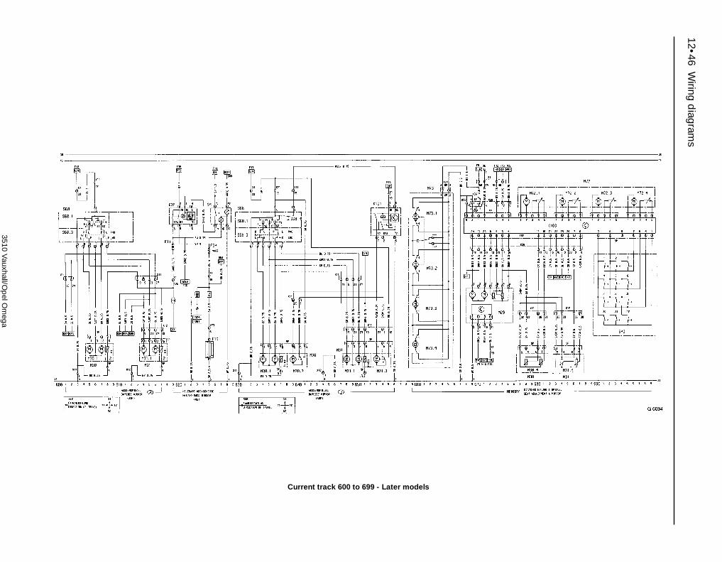
12•46W
iring diagram
s
3510 Vauxhall/O
pel O
mega
Current track 600 to 699 - Later models

Wiring d
iagrams 12•47
12
3510 Vauxhall/O
pel O
mega
Current track 700 to 799 - Later models

12•48W
iring diagram
s
3510 Vauxhall/O
pel O
mega
Current track 800 to 899 - Later models
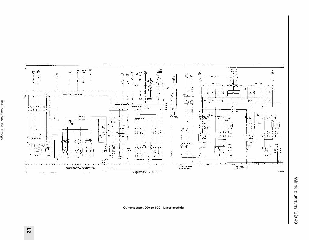
Wiring d
iagrams 12•49
12
3510 Vauxhall/O
pel O
mega
Current track 900 to 999 - Later models

12•50W
iring diagram
s
3510 Vauxhall/O
pel O
mega
Current track 1000 to 1099 - Later models

Wiring d
iagrams 12•51
12
3510 Vauxhall/O
pel O
mega
Current track 1100 to 1199 - Later models
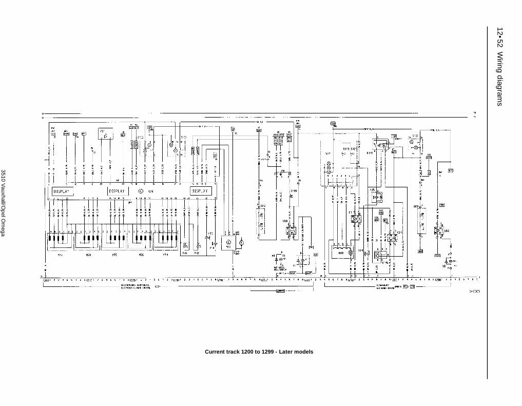
12•52W
iring diagram
s
3510 Vauxhall/O
pel O
mega
Current track 1200 to 1299 - Later models

Wiring d
iagrams 12•53
12
3510 Vauxhall/O
pel O
mega
Current track 1300 to 1399 - Later models
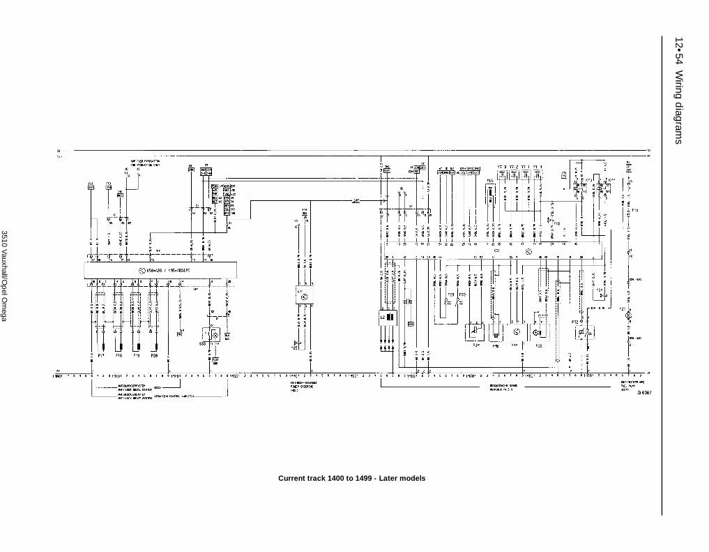
12•54W
iring diagram
s
3510 Vauxhall/O
pel O
mega
Current track 1400 to 1499 - Later models

Wiring d
iagrams 12•55
12
3510 Vauxhall/O
pel O
mega
Current track 1500 to 1599 - Later models

12•56W
iring diagram
s
3510 Vauxhall/O
pel O
mega
Current track 1600 to 1699 - Later models

Reference REF•1
3510 Vauxhall/Opel Omega
Dimensions and WeightsNote: All figures are approximate, and may vary according to model depending on specification. Refer to manufacturer’s data for exact figures.
Dimensions Saloon model Estate modelOverall length . . . . . . . . . . . . . . . . . . . . . . . . . . . . . . . . . . . . . . . . . . . . . 4787 mm 4819 mmOverall width . . . . . . . . . . . . . . . . . . . . . . . . . . . . . . . . . . . . . . . . . . . . . . 1960 mm 1960 mmOverall height (unladen) . . . . . . . . . . . . . . . . . . . . . . . . . . . . . . . . . . . . . 1455 mm 1545 mmWheelbase . . . . . . . . . . . . . . . . . . . . . . . . . . . . . . . . . . . . . . . . . . . . . . . 2730 mm 2730 mmGround clearance . . . . . . . . . . . . . . . . . . . . . . . . . . . . . . . . . . . . . . . . . . 135 mm 142 mm
Weights Saloon model Estate modelKerb weight:*
2.0 litre engine . . . . . . . . . . . . . . . . . . . . . . . . . . . . . . . . . . . . . . . . . . 1400 to 1475 kg 1460 to 1540 kg2.5 litre engine . . . . . . . . . . . . . . . . . . . . . . . . . . . . . . . . . . . . . . . . . . 1510 to 1570 kg 1560 to 1623 kg3.0 litre engine . . . . . . . . . . . . . . . . . . . . . . . . . . . . . . . . . . . . . . . . . . 1575 to 1625 kg 1625 to 1675 kg
Maximum gross vehicle weight:*2.0 litre engine . . . . . . . . . . . . . . . . . . . . . . . . . . . . . . . . . . . . . . . . . . 1955 to 1985 kg 2085 to 2165 kg2.5 litre engine . . . . . . . . . . . . . . . . . . . . . . . . . . . . . . . . . . . . . . . . . . 2065 to 2095 kg 2195 to 2225 kg3.0 litre engine . . . . . . . . . . . . . . . . . . . . . . . . . . . . . . . . . . . . . . . . . . 2095 to 2125 kg 2200 to 2250 kg
Maximum roof rack load . . . . . . . . . . . . . . . . . . . . . . . . . . . . . . . . . . . . . 100 kg (including the weight of the roof rack)Maximum trailer nose weight . . . . . . . . . . . . . . . . . . . . . . . . . . . . . . . . . 75 kg*Depending on specification - refer to manufacturer’s vehicle handbook for exact amount
Dimensions and Weights . . . . . . . . . . . . . . . . . . .REF•1Conversion Factors . . . . . . . . . . . . . . . . . . . . . . . .REF•2Buying Spare Parts . . . . . . . . . . . . . . . . . . . . . . . .REF•3Vehicle Identification . . . . . . . . . . . . . . . . . . . . . . .REF•3General Repair Procedures . . . . . . . . . . . . . . . . . .REF•4Jacking and Vehicle Support . . . . . . . . . . . . . . . .REF•5
Radio/cassette unit Anti-theft System precaution . .REF•5Tools and Working Facilities . . . . . . . . . . . . . . . . .REF•6MOT Test Checks . . . . . . . . . . . . . . . . . . . . . . . . .REF•8Fault Finding . . . . . . . . . . . . . . . . . . . . . . . . . . . .REF•12Glossary of Technical Terms . . . . . . . . . . . . . . . .REF•20Index . . . . . . . . . . . . . . . . . . . . . . . . . . . . . . . . . .REF•24

REF•2 Conversion factors
3510 Vauxhall/Opel Omega
Length (distance)Inches (in) x 25.4 = Millimetres (mm) x 0.0394 = Inches (in)Feet (ft) x 0.305 = Metres (m) x 3.281 = Feet (ft)Miles x 1.609 = Kilometres (km) x 0.621 = Miles
Volume (capacity)Cubic inches (cu in; in3) x 16.387 = Cubic centimetres (cc; cm3) x 0.061 = Cubic inches (cu in; in3)Imperial pints (Imp pt) x 0.568 = Litres (l) x 1.76 = Imperial pints (Imp pt)Imperial quarts (Imp qt) x 1.137 = Litres (l) x 0.88 = Imperial quarts (Imp qt)Imperial quarts (Imp qt) x 1.201 = US quarts (US qt) x 0.833 = Imperial quarts (Imp qt)US quarts (US qt) x 0.946 = Litres (l) x 1.057 = US quarts (US qt)Imperial gallons (Imp gal) x 4.546 = Litres (l) x 0.22 = Imperial gallons (Imp gal)Imperial gallons (Imp gal) x 1.201 = US gallons (US gal) x 0.833 = Imperial gallons (Imp gal)US gallons (US gal) x 3.785 = Litres (l) x 0.264 = US gallons (US gal)
Mass (weight)Ounces (oz) x 28.35 = Grams (g) x 0.035 = Ounces (oz)Pounds (lb) x 0.454 = Kilograms (kg) x 2.205 = Pounds (lb)
ForceOunces-force (ozf; oz) x 0.278 = Newtons (N) x 3.6 = Ounces-force (ozf; oz)Pounds-force (lbf; lb) x 4.448 = Newtons (N) x 0.225 = Pounds-force (lbf; lb)Newtons (N) x 0.1 = Kilograms-force (kgf; kg) x 9.81 = Newtons (N)
PressurePounds-force per square inch x 0.070 = Kilograms-force per square x 14.223 = Pounds-force per square inch(psi; lbf/in2; lb/in2) centimetre (kgf/cm2; kg/cm2) (psi; lbf/in2; lb/in2)Pounds-force per square inch x 0.068 = Atmospheres (atm) x 14.696 = Pounds-force per square inch(psi; lbf/in2; lb/in2) (psi; lbf/in2; lb/in2)Pounds-force per square inch x 0.069 = Bars x 14.5 = Pounds-force per square inch(psi; lbf/in2; lb/in2) (psi; lbf/in2; lb/in2)Pounds-force per square inch x 6.895 = Kilopascals (kPa) x 0.145 = Pounds-force per square inch(psi; lbf/in2; lb/in2) (psi; lbf/in2; lb/in2)Kilopascals (kPa) x 0.01 = Kilograms-force per square x 98.1 = Kilopascals (kPa)
centimetre (kgf/cm2; kg/cm2)Millibar (mbar) x 100 = Pascals (Pa) x 0.01 = Millibar (mbar)Millibar (mbar) x 0.0145 = Pounds-force per square inch x 68.947 = Millibar (mbar)
(psi; lbf/in2; lb/in2)Millibar (mbar) x 0.75 = Millimetres of mercury (mmHg) x 1.333 = Millibar (mbar)Millibar (mbar) x 0.401 = Inches of water (inH2O) x 2.491 = Millibar (mbar)Millimetres of mercury (mmHg) x 0.535 = Inches of water (inH2O) x 1.868 = Millimetres of mercury (mmHg)Inches of water (inH2O) x 0.036 = Pounds-force per square inch x 27.68 = Inches of water (inH2O)
(psi; lbf/in2; lb/in2)
Torque (moment of force)Pounds-force inches x 1.152 = Kilograms-force centimetre x 0.868 = Pounds-force inches(lbf in; lb in) (kgf cm; kg cm) (lbf in; lb in)Pounds-force inches x 0.113 = Newton metres (Nm) x 8.85 = Pounds-force inches(lbf in; lb in) (lbf in; lb in)Pounds-force inches x 0.083 = Pounds-force feet (lbf ft; lb ft) x 12 = Pounds-force inches(lbf in; lb in) (lbf in; lb in)Pounds-force feet (lbf ft; lb ft) x 0.138 = Kilograms-force metres x 7.233 = Pounds-force feet (lbf ft; lb ft)
(kgf m; kg m)Pounds-force feet (lbf ft; lb ft) x 1.356 = Newton metres (Nm) x 0.738 = Pounds-force feet (lbf ft; lb ft)Newton metres (Nm) x 0.102 = Kilograms-force metres x 9.804 = Newton metres (Nm)
(kgf m; kg m)
PowerHorsepower (hp) x 745.7 = Watts (W) x 0.0013 = Horsepower (hp)
Velocity (speed)Miles per hour (miles/hr; mph) x 1.609 = Kilometres per hour (km/hr; kph) x 0.621 = Miles per hour (miles/hr; mph)
Fuel consumption*Miles per gallon, Imperial (mpg) x 0.354 = Kilometres per litre (km/l) x 2.825 = Miles per gallon, Imperial (mpg)Miles per gallon, US (mpg) x 0.425 = Kilometres per litre (km/l) x 2.352 = Miles per gallon, US (mpg)
TemperatureDegrees Fahrenheit = (°C x 1.8) + 32 Degrees Celsius (Degrees Centigrade; °C) = (°F - 32) x 0.56
* It is common practice to convert from miles per gallon (mpg) to litres/100 kilometres (l/100km), where mpg x l/100 km = 282

Spare parts are available from manysources, including maker’s appointedgarages, accessory shops, and motor factors.To be sure of obtaining the correct parts, itwill sometimes be necessary to quote thevehicle identification number. If possible, itcan also be useful to take the old parts alongfor positive identification. Items such asstarter motors and alternators may beavailable under a service exchange scheme -any parts returned should be clean.
Our advice regarding spare parts is asfollows.
Officially appointed garagesThis is the best source of parts which are
peculiar to your car, and which are nototherwise generally available (eg, badges,interior trim, certain body panels, etc). It isalso the only place at which you should buyparts if the vehicle is still under warranty.
Accessory shopsThese are very good places to buy
materials and components needed for themaintenance of your car (oil, air and fuel
filters, light bulbs, drivebelts, greases, brakepads, touch-up paint, etc). Components ofthis nature sold by a reputable shop areusually of the same standard as those usedby the car manufacturer.
Besides components, these shops also selltools and general accessories, usually haveconvenient opening hours, charge lowerprices, and can often be found close to home.Some accessory shops have parts counterswhere components needed for almost anyrepair job can be purchased or ordered.
Motor factorsGood factors will stock all the more
important components which wear outcomparatively quickly, and can sometimessupply individual components needed for theoverhaul of a larger assembly (eg, brake sealsand hydraulic parts, bearing shells, pistons,valves). They may also handle work such ascylinder block reboring, crankshaft regrinding,etc.
Tyre and exhaust specialistsThese outlets may be independent, or
members of a local or national chain. Theyfrequently offer competitive prices whencompared with a main dealer or local garage,but it will pay to obtain several quotes beforemaking a decision. When researching prices,also ask what extras may be added - forinstance fitting a new valve and balancing thewheel are both commonly charged on top ofthe price of a new tyre.
Other sourcesBeware of parts or materials obtained from
market stalls, car boot sales or similar outlets.Such items are not invariably sub-standard,but there is little chance of compensation ifthey do prove unsatisfactory. in the case ofsafety-critical components such as brakepads, there is the risk not only of financialloss, but also of an accident causing injury ordeath.
Second-hand components or assembliesobtained from a car breaker can be a goodbuy in some circumstances, but this sort ofpurchase is best made by the experiencedDIY mechanic.
Modifications are a continuing andunpublicised process in vehicle manufacture,quite apart from major model changes. Spareparts manuals and lists are compiled upon anumerical basis, the individual vehicleidentification numbers being essential tocorrect identification of the componentconcerned.
When ordering spare parts, always give asmuch information as possible. Quote the car
model, year of manufacture and registration,chassis and engine numbers as appropriate.
The Vehicle Identification Number (VIN) plateis riveted to the bonnet lock crossmember, onthe right-hand side of the lock, and is visibleonce the bonnet has been opened. The vehicleidentification (chassis) number is also stampedonto the body floor panel between the driver’sseat and sill panel; lift the flap in the trim panelto see it (see illustrations).
The engine number can be found on theleft-hand side of the cylinder block. The firstfive digits of the engine number form theengine identification code.Note: The vehicle is supplied with a Car Pass(similar to a credit card) which has all thevehicle identification data recorded on amagnetic strip. This card should be stored in asafe place away from the vehicle.
Buying spare parts REF•3
3510 Vauxhall/Opel Omega
Vehicle Identification
The VIN plate (arrowed) is riveted to the bonnet lockcrossmember
The VIN (chassis) number is also stamped on the floor betweenthe driver’s seat and sill panel. Open up the trim panel flap
(arrowed) to see it

REF•4 General repair procedures
3510 Vauxhall/Opel Omega
Whenever servicing, repair or overhaul workis carried out on the car or its components,observe the following procedures andinstructions. This will assist in carrying out theoperation efficiently and to a professionalstandard of workmanship.
Joint mating faces and gasketsWhen separating components at their
mating faces, never insert screwdrivers orsimilar implements into the joint between thefaces in order to prise them apart. This cancause severe damage which results in oilleaks, coolant leaks, etc upon reassembly.Separation is usually achieved by tappingalong the joint with a soft-faced hammer inorder to break the seal. However, note thatthis method may not be suitable wheredowels are used for component location.
Where a gasket is used between the matingfaces of two components, a new one must befitted on reassembly; fit it dry unless otherwisestated in the repair procedure. Make sure thatthe mating faces are clean and dry, with alltraces of old gasket removed. When cleaning ajoint face, use a tool which is unlikely to scoreor damage the face, and remove any burrs ornicks with an oilstone or fine file.
Make sure that tapped holes are cleanedwith a pipe cleaner, and keep them free ofjointing compound, if this is being used,unless specifically instructed otherwise.
Ensure that all orifices, channels or pipesare clear, and blow through them, preferablyusing compressed air.
Oil sealsOil seals can be removed by levering them
out with a wide flat-bladed screwdriver or similarimplement. Alternatively, a number of self-tapping screws may be screwed into the seal,and these used as a purchase for pliers or somesimilar device in order to pull the seal free.
Whenever an oil seal is removed from itsworking location, either individually or as partof an assembly, it should be renewed.
The very fine sealing lip of the seal is easilydamaged, and will not seal if the surface itcontacts is not completely clean and free fromscratches, nicks or grooves. If the originalsealing surface of the component cannot berestored, and the manufacturer has not madeprovision for slight relocation of the sealrelative to the sealing surface, the componentshould be renewed.
Protect the lips of the seal from any surfacewhich may damage them in the course offitting. Use tape or a conical sleeve wherepossible. Lubricate the seal lips with oil beforefitting and, on dual-lipped seals, fill the spacebetween the lips with grease.
Unless otherwise stated, oil seals must befitted with their sealing lips toward thelubricant to be sealed.
Use a tubular drift or block of wood of theappropriate size to install the seal and, if theseal housing is shouldered, drive the sealdown to the shoulder. If the seal housing is
unshouldered, the seal should be fitted withits face flush with the housing top face (unlessotherwise instructed).
Screw threads and fasteningsSeized nuts, bolts and screws are quite a
common occurrence where corrosion has setin, and the use of penetrating oil or releasingfluid will often overcome this problem if theoffending item is soaked for a while beforeattempting to release it. The use of an impactdriver may also provide a means of releasingsuch stubborn fastening devices, when usedin conjunction with the appropriatescrewdriver bit or socket. If none of thesemethods works, it may be necessary to resortto the careful application of heat, or the use ofa hacksaw or nut splitter device.
Studs are usually removed by locking twonuts together on the threaded part, and thenusing a spanner on the lower nut to unscrewthe stud. Studs or bolts which have broken offbelow the surface of the component in whichthey are mounted can sometimes be removedusing a stud extractor. Always ensure that ablind tapped hole is completely free from oil,grease, water or other fluid before installingthe bolt or stud. Failure to do this could causethe housing to crack due to the hydraulicaction of the bolt or stud as it is screwed in.
When tightening a castellated nut to accepta split pin, tighten the nut to the specifiedtorque, where applicable, and then tightenfurther to the next split pin hole. Never slackenthe nut to align the split pin hole, unless statedin the repair procedure.
When checking or retightening a nut or boltto a specified torque setting, slacken the nutor bolt by a quarter of a turn, and thenretighten to the specified setting. However,this should not be attempted where angulartightening has been used.
For some screw fastenings, notablycylinder head bolts or nuts, torque wrenchsettings are no longer specified for the latterstages of tightening, “angle-tightening” beingcalled up instead. Typically, a fairly low torquewrench setting will be applied to thebolts/nuts in the correct sequence, followedby one or more stages of tightening throughspecified angles.
Locknuts, locktabs and washersAny fastening which will rotate against a
component or housing during tighteningshould always have a washer between it andthe relevant component or housing.
Spring or split washers should always berenewed when they are used to lock a criticalcomponent such as a big-end bearingretaining bolt or nut. Locktabs which arefolded over to retain a nut or bolt shouldalways be renewed.
Self-locking nuts can be re-used in non-critical areas, providing resistance can be feltwhen the locking portion passes over the boltor stud thread. However, it should be notedthat self-locking stiffnuts tend to lose their
effectiveness after long periods of use, andshould then be renewed as a matter of course.
Split pins must always be replaced withnew ones of the correct size for the hole.
When thread-locking compound is foundon the threads of a fastener which is to be re-used, it should be cleaned off with a wirebrush and solvent, and fresh compoundapplied on reassembly.
Special toolsSome repair procedures in this manual
entail the use of special tools such as a press,two or three-legged pullers, spring com-pressors, etc. Wherever possible, suitablereadily-available alternatives to the manu-facturer’s special tools are described, and areshown in use. In some instances, where noalternative is possible, it has been necessaryto resort to the use of a manufacturer’s tool,and this has been done for reasons of safetyas well as the efficient completion of the repairoperation. Unless you are highly-skilled andhave a thorough understanding of theprocedures described, never attempt tobypass the use of any special tool when theprocedure described specifies its use. Notonly is there a very great risk of personalinjury, but expensive damage could becaused to the components involved.
Environmental considerationsWhen disposing of used engine oil, brake
fluid, antifreeze, etc, give due consideration toany detrimental environmental effects. Do not,for instance, pour any of the above liquidsdown drains into the general sewage system,or onto the ground to soak away. Many localcouncil refuse tips provide a facility for wasteoil disposal, as do some garages. If none ofthese facilities are available, consult your localEnvironmental Health Department, or theNational Rivers Authority, for further advice.
With the universal tightening-up of legis-lation regarding the emission of environmen-tally-harmful substances from motor vehicles,most vehicles have tamperproof devices fittedto the main adjustment points of the fuelsystem. These devices are primarily designedto prevent unqualified persons from adjustingthe fuel/air mixture, with the chance of aconsequent increase in toxic emissions. Ifsuch devices are found during servicing oroverhaul, they should, wherever possible, berenewed or refitted in accordance with themanufacturer’s requirements or currentlegislation.
Note: It isantisocial andillegal to dumpoil down thedrain. To findthe location ofyour local oilrecycling bank,call thisnumber free.
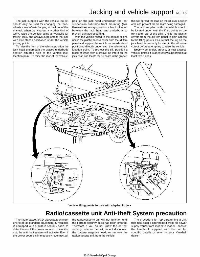
The jack supplied with the vehicle tool kitshould only be used for changing the road-wheels - see Wheel changing at the front of thismanual. When carrying out any other kind ofwork, raise the vehicle using a hydraulic (ortrolley) jack, and always supplement the jackwith axle stands positioned under the vehiclejacking points.
To raise the front of the vehicle, position thejack head underneath the braced underbodysection situated next to the vehicle jacklocation point. To raise the rear of the vehicle,
position the jack head underneath the rearsuspension subframe front mounting (seeillustration). Always position a block of woodbetween the jack head and underbody toprevent damage occurring.
With the vehicle raised to the correct height,unclip the plastic access cover from the sill trimpanel and support the vehicle on an axle standpositioned directly underneath the vehicle jacklocation point. To protect the sill, position ablock of wood with a groove cut into it on thejack head and locate the sill seam in the groove;
this will spread the load on the sill over a widerarea and prevent the sill seam being damaged.
The jack supplied with the vehicle shouldbe located underneath the lifting points on thefront and rear of the sills. Unclip the plasticcovers from the sill trim panel to gain accessto the lifting points. Ensure that the lug on thejack head is correctly located in the sill seamcutout before attempting to raise the vehicle.
Never work under, around, or near a raisedvehicle, unless it is adequately supported in atleast two places.
The radio/cassette/CD player/autochangerunit fitted as standard equipment by Vauxhallis equipped with a built-in security code, todeter thieves. If the power source to the unit iscut, the anti-theft system will activate. Even ifthe power source is immediately reconnected,
the radio/cassette unit will not function untilthe correct security code has been entered.Therefore if you do not know the correctsecurity code for the unit, do not disconnectthe battery negative lead, or remove theradio/cassette unit from the vehicle.
The procedure for reprogramming a unitthat has been disconnected from its powersupply varies from model to model - consultthe handbook supplied with the unit forspecific details or refer to your Vauxhalldealer.
Jacking and vehicle support REF•5
3510 Vauxhall/Opel Omega
Radio/cassette unit Anti-theft System precaution
Vehicle lifting points for use with a hydraulic jack
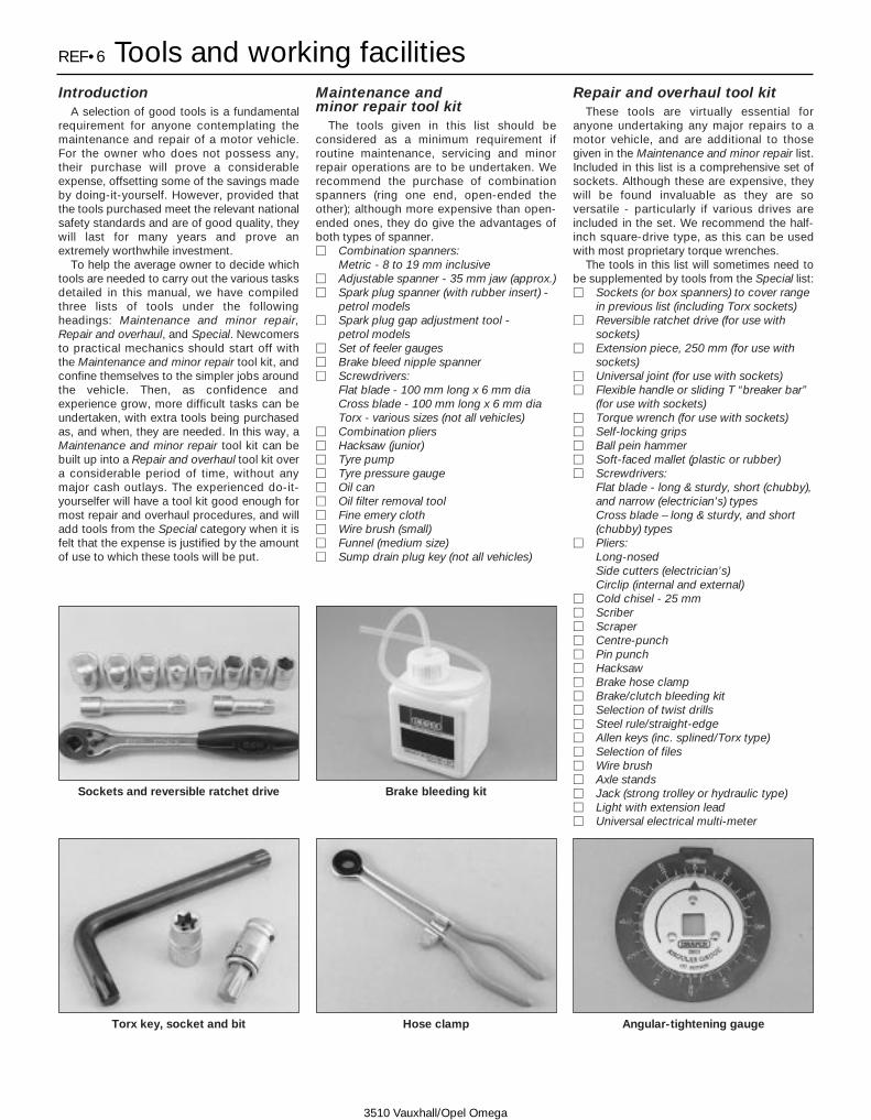
REF•6 Tools and working facilities
3510 Vauxhall/Opel Omega
IntroductionA selection of good tools is a fundamental
requirement for anyone contemplating themaintenance and repair of a motor vehicle.For the owner who does not possess any,their purchase will prove a considerableexpense, offsetting some of the savings madeby doing-it-yourself. However, provided thatthe tools purchased meet the relevant nationalsafety standards and are of good quality, theywill last for many years and prove anextremely worthwhile investment.
To help the average owner to decide whichtools are needed to carry out the various tasksdetailed in this manual, we have compiledthree lists of tools under the followingheadings: Maintenance and minor repair,Repair and overhaul, and Special. Newcomersto practical mechanics should start off withthe Maintenance and minor repair tool kit, andconfine themselves to the simpler jobs aroundthe vehicle. Then, as confidence andexperience grow, more difficult tasks can beundertaken, with extra tools being purchasedas, and when, they are needed. In this way, aMaintenance and minor repair tool kit can bebuilt up into a Repair and overhaul tool kit overa considerable period of time, without anymajor cash outlays. The experienced do-it-yourselfer will have a tool kit good enough formost repair and overhaul procedures, and willadd tools from the Special category when it isfelt that the expense is justified by the amountof use to which these tools will be put.
Maintenance and minor repair tool kit
The tools given in this list should beconsidered as a minimum requirement ifroutine maintenance, servicing and minorrepair operations are to be undertaken. Werecommend the purchase of combinationspanners (ring one end, open-ended theother); although more expensive than open-ended ones, they do give the advantages ofboth types of spanner.M Combination spanners:
Metric - 8 to 19 mm inclusiveM Adjustable spanner - 35 mm jaw (approx.)M Spark plug spanner (with rubber insert) -
petrol modelsM Spark plug gap adjustment tool -
petrol modelsM Set of feeler gaugesM Brake bleed nipple spannerM Screwdrivers:
Flat blade - 100 mm long x 6 mm diaCross blade - 100 mm long x 6 mm diaTorx - various sizes (not all vehicles)
M Combination pliersM Hacksaw (junior)M Tyre pumpM Tyre pressure gaugeM Oil canM Oil filter removal toolM Fine emery clothM Wire brush (small)M Funnel (medium size)M Sump drain plug key (not all vehicles)
Repair and overhaul tool kitThese tools are virtually essential for
anyone undertaking any major repairs to amotor vehicle, and are additional to thosegiven in the Maintenance and minor repair list.Included in this list is a comprehensive set ofsockets. Although these are expensive, theywill be found invaluable as they are soversatile - particularly if various drives areincluded in the set. We recommend the half-inch square-drive type, as this can be usedwith most proprietary torque wrenches.
The tools in this list will sometimes need tobe supplemented by tools from the Special list:M Sockets (or box spanners) to cover range
in previous list (including Torx sockets)M Reversible ratchet drive (for use with
sockets)M Extension piece, 250 mm (for use with
sockets)M Universal joint (for use with sockets)M Flexible handle or sliding T “breaker bar”
(for use with sockets)M Torque wrench (for use with sockets)M Self-locking gripsM Ball pein hammerM Soft-faced mallet (plastic or rubber)M Screwdrivers:
Flat blade - long & sturdy, short (chubby),and narrow (electrician’s) typesCross blade – long & sturdy, and short(chubby) types
M Pliers:Long-nosedSide cutters (electrician’s)Circlip (internal and external)
M Cold chisel - 25 mmM ScriberM ScraperM Centre-punchM Pin punchM HacksawM Brake hose clampM Brake/clutch bleeding kitM Selection of twist drillsM Steel rule/straight-edgeM Allen keys (inc. splined/Torx type)M Selection of filesM Wire brushM Axle standsM Jack (strong trolley or hydraulic type)M Light with extension leadM Universal electrical multi-meter
Sockets and reversible ratchet drive Brake bleeding kit
Torx key, socket and bit Hose clamp Angular-tightening gauge

Tools and working facilities REF•7
3510 Vauxhall/Opel Omega
Special toolsThe tools in this list are those which are not
used regularly, are expensive to buy, or whichneed to be used in accordance with theirmanufacturers’ instructions. Unless relativelydifficult mechanical jobs are undertakenfrequently, it will not be economic to buymany of these tools. Where this is the case,you could consider clubbing together withfriends (or joining a motorists’ club) to make ajoint purchase, or borrowing the tools againsta deposit from a local garage or tool hirespecialist. It is worth noting that many of thelarger DIY superstores now carry a largerange of special tools for hire at modestrates.
The following list contains only those toolsand instruments freely available to the public,and not those special tools produced by thevehicle manufacturer specifically for its dealernetwork. You will find occasional referencesto these manufacturers’ special tools in thetext of this manual. Generally, an alternativemethod of doing the job without the vehiclemanufacturers’ special tool is given. However,sometimes there is no alternative to usingthem. Where this is the case and the relevanttool cannot be bought or borrowed, you willhave to entrust the work to a dealer.M Angular-tightening gaugeM Valve spring compressorM Valve grinding toolM Piston ring compressorM Piston ring removal/installation toolM Cylinder bore honeM Balljoint separatorM Coil spring compressors (where applicable)M Two/three-legged hub and bearing pullerM Impact screwdriverM Micrometer and/or vernier calipersM Dial gaugeM Stroboscopic timing lightM Dwell angle meter/tachometerM Fault code readerM Cylinder compression gaugeM Hand-operated vacuum pump and gaugeM Clutch plate alignment setM Brake shoe steady spring cup removal toolM Bush and bearing removal/installation setM Stud extractorsM Tap and die setM Lifting tackleM Trolley jack
Buying toolsReputable motor accessory shops and
superstores often offer excellent quality toolsat discount prices, so it pays to shop around.
Remember, you don’t have to buy the mostexpensive items on the shelf, but it is alwaysadvisable to steer clear of the very cheaptools. Beware of ‘bargains’ offered on marketstalls or at car boot sales. There are plenty ofgood tools around at reasonable prices, butalways aim to purchase items which meet therelevant national safety standards. If in doubt,ask the proprietor or manager of the shop foradvice before making a purchase.
Care and maintenance of toolsHaving purchased a reasonable tool kit, it is
necessary to keep the tools in a clean andserviceable condition. After use, always wipeoff any dirt, grease and metal particles using aclean, dry cloth, before putting the tools away.Never leave them lying around after they havebeen used. A simple tool rack on the garageor workshop wall for items such asscrewdrivers and pliers is a good idea. Storeall normal spanners and sockets in a metalbox. Any measuring instruments, gauges,meters, etc, must be carefully stored wherethey cannot be damaged or become rusty.
Take a little care when tools are used.Hammer heads inevitably become marked,and screwdrivers lose the keen edge on theirblades from time to time. A little timelyattention with emery cloth or a file will soonrestore items like this to a good finish.
Working facilitiesNot to be forgotten when discussing tools
is the workshop itself. If anything more thanroutine maintenance is to be carried out, asuitable working area becomes essential.
It is appreciated that many an owner-mechanic is forced by circumstances toremove an engine or similar item without thebenefit of a garage or workshop. Having donethis, any repairs should always be done underthe cover of a roof.
Wherever possible, any dismantling shouldbe done on a clean, flat workbench or table ata suitable working height.
Any workbench needs a vice; one with ajaw opening of 100 mm is suitable for mostjobs. As mentioned previously, some cleandry storage space is also required for tools, aswell as for any lubricants, cleaning fluids,touch-up paints etc, which becomenecessary.
Another item which may be required, andwhich has a much more general usage, is anelectric drill with a chuck capacity of at least8 mm. This, together with a good range oftwist drills, is virtually essential for fittingaccessories.
Last, but not least, always keep a supply ofold newspapers and clean, lint-free ragsavailable, and try to keep any working area asclean as possible.
Micrometers Dial test indicator (“dial gauge”)
Strap wrench Compression tester Fault code reader
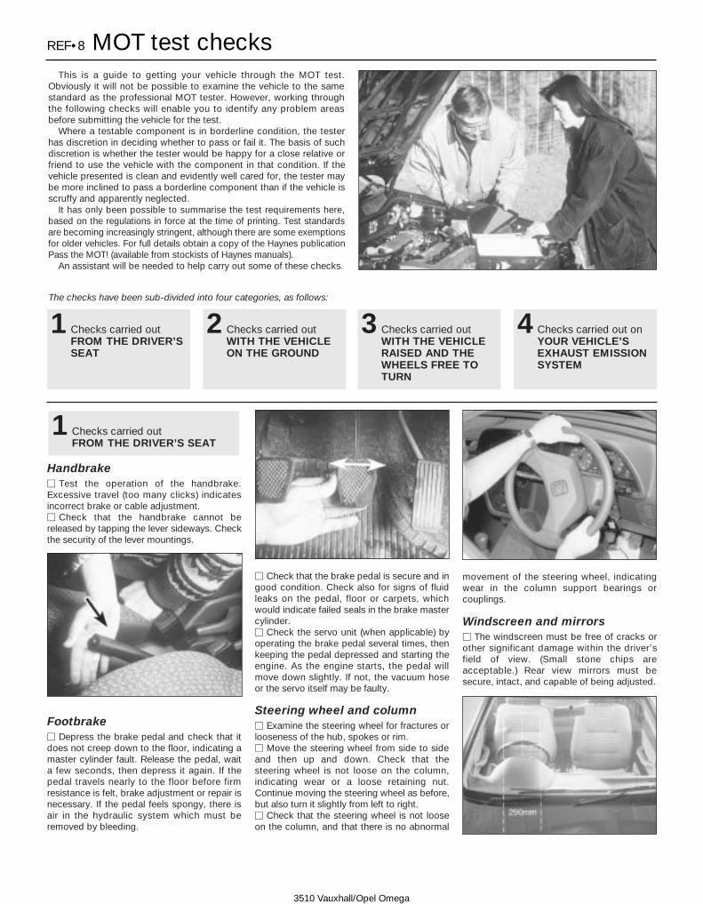
REF•8 MOT test checks
3510 Vauxhall/Opel Omega
This is a guide to getting your vehicle through the MOT test.Obviously it will not be possible to examine the vehicle to the samestandard as the professional MOT tester. However, working throughthe following checks will enable you to identify any problem areasbefore submitting the vehicle for the test.
Where a testable component is in borderline condition, the testerhas discretion in deciding whether to pass or fail it. The basis of suchdiscretion is whether the tester would be happy for a close relative orfriend to use the vehicle with the component in that condition. If thevehicle presented is clean and evidently well cared for, the tester maybe more inclined to pass a borderline component than if the vehicle isscruffy and apparently neglected.
It has only been possible to summarise the test requirements here,based on the regulations in force at the time of printing. Test standardsare becoming increasingly stringent, although there are some exemptionsfor older vehicles. For full details obtain a copy of the Haynes publicationPass the MOT! (available from stockists of Haynes manuals).
An assistant will be needed to help carry out some of these checks.
The checks have been sub-divided into four categories, as follows:
1Checks carried outFROM THE DRIVER’SSEAT
2Checks carried outWITH THE VEHICLEON THE GROUND
3Checks carried outWITH THE VEHICLERAISED AND THEWHEELS FREE TOTURN
4Checks carried out onYOUR VEHICLE’SEXHAUST EMISSIONSYSTEM
HandbrakeM Test the operation of the handbrake.Excessive travel (too many clicks) indicatesincorrect brake or cable adjustment.M Check that the handbrake cannot bereleased by tapping the lever sideways. Checkthe security of the lever mountings.
FootbrakeM Depress the brake pedal and check that itdoes not creep down to the floor, indicating amaster cylinder fault. Release the pedal, waita few seconds, then depress it again. If thepedal travels nearly to the floor before firmresistance is felt, brake adjustment or repair isnecessary. If the pedal feels spongy, there isair in the hydraulic system which must beremoved by bleeding.
M Check that the brake pedal is secure and ingood condition. Check also for signs of fluidleaks on the pedal, floor or carpets, whichwould indicate failed seals in the brake mastercylinder.M Check the servo unit (when applicable) byoperating the brake pedal several times, thenkeeping the pedal depressed and starting theengine. As the engine starts, the pedal willmove down slightly. If not, the vacuum hoseor the servo itself may be faulty.
Steering wheel and column M Examine the steering wheel for fractures orlooseness of the hub, spokes or rim. M Move the steering wheel from side to sideand then up and down. Check that the steering wheel is not loose on the column,indicating wear or a loose retaining nut.Continue moving the steering wheel as before,but also turn it slightly from left to right. M Check that the steering wheel is not looseon the column, and that there is no abnormal
movement of the steering wheel, indicatingwear in the column support bearings or couplings.
Windscreen and mirrors M The windscreen must be free of cracks orother significant damage within the driver’sfield of view. (Small stone chips areacceptable.) Rear view mirrors must besecure, intact, and capable of being adjusted.
1Checks carried outFROM THE DRIVER’S SEAT

MOT test checks REF•9
3510 Vauxhall/Opel Omega
Seat belts and seats Note: The following checks are applicable toall seat belts, front and rear.
M Examine the webbing of all the belts(including rear belts if fitted) for cuts, seriousfraying or deterioration. Fasten and unfasteneach belt to check the buckles. If applicable,check the retracting mechanism. Check thesecurity of all seat belt mountings accessiblefrom inside the vehicle.M The front seats themselves must besecurely attached and the backrests mustlock in the upright position.
Doors M Both front doors must be able to be openedand closed from outside and inside, and mustlatch securely when closed.
Vehicle identificationM Number plates must be in good condition,secure and legible, with letters and numberscorrectly spaced – spacing at (A) should betwice that at (B).
M The VIN plate and/or homologation platemust be legible.
Electrical equipmentM Switch on the ignition and check the operation of the horn.M Check the windscreen washers and wipers,examining the wiper blades; renew damagedor perished blades. Also check the operationof the stop-lights.
M Check the operation of the sidelights andnumber plate lights. The lenses and reflectorsmust be secure, clean and undamaged. M Check the operation and alignment of theheadlights. The headlight reflectors must notbe tarnished and the lenses must beundamaged.M Switch on the ignition and check the operation of the direction indicators (includingthe instrument panel tell-tale) and the hazardwarning lights. Operation of the sidelights andstop-lights must not affect the indicators - if itdoes, the cause is usually a bad earth at therear light cluster.M Check the operation of the rear foglight(s),including the warning light on the instrumentpanel or in the switch.
FootbrakeM Examine the master cylinder, brake pipesand servo unit for leaks, loose mountings, corrosion or other damage.
M The fluid reservoir must be secure and thefluid level must be between the upper (A) andlower (B) markings.
M Inspect both front brake flexible hoses forcracks or deterioration of the rubber. Turn thesteering from lock to lock, and ensure that thehoses do not contact the wheel, tyre, or anypart of the steering or suspension mechanism.With the brake pedal firmly depressed, checkthe hoses for bulges or leaks under pressure.
Steering and suspensionM Have your assistant turn the steering wheelfrom side to side slightly, up to the pointwhere the steering gear just begins to transmitthis movement to the roadwheels. Check forexcessive free play between the steeringwheel and the steering gear, indicating wearor insecurity of the steering column joints, thecolumn-to-steering gear coupling, or thesteering gear itself.M Have your assistant turn the steering wheelmore vigorously in each direction, so that theroadwheels just begin to turn. As this is done,examine all the steering joints, linkages,fittings and attachments. Renew anycomponent that shows signs of wear or damage. On vehicles with power steering,check the security and condition of the steering pump, drivebelt and hoses.M Check that the vehicle is standing level,and at approximately the correct ride height.
Shock absorbersM Depress each corner of the vehicle in turn,then release it. The vehicle should rise andthen settle in its normal position. If the vehiclecontinues to rise and fall, the shock absorberis defective. A shock absorber which hasseized will also cause the vehicle to fail.
2Checks carried outWITH THE VEHICLE ON THEGROUND

REF•10 MOT test checks
3510 Vauxhall/Opel Omega
Exhaust systemM Start the engine. With your assistant holding a rag over the tailpipe, check theentire system for leaks. Repair or renewleaking sections.
Jack up the front and rear of the vehicle,and securely support it on axle stands.Position the stands clear of the suspensionassemblies. Ensure that the wheels areclear of the ground and that the steeringcan be turned from lock to lock.
Steering mechanism M Have your assistant turn the steering fromlock to lock. Check that the steering turnssmoothly, and that no part of the steeringmechanism, including a wheel or tyre, foulsany brake hose or pipe or any part of the bodystructure.M Examine the steering rack rubber gaitersfor damage or insecurity of the retaining clips.If power steering is fitted, check for signs ofdamage or leakage of the fluid hoses, pipes orconnections. Also check for excessivestiffness or binding of the steering, a missingsplit pin or locking device, or severe corrosionof the body structure within 30 cm of anysteering component attachment point.
Front and rear suspension andwheel bearings M Starting at the front right-hand side, graspthe roadwheel at the 3 o’clock and 9 o’clockpositions and shake it vigorously. Check forfree play or insecurity at the wheel bearings,suspension balljoints, or suspension mount-ings, pivots and attachments.M Now grasp the wheel at the 12 o’clock and6 o’clock positions and repeat the previousinspection. Spin the wheel, and check forroughness or tightness of the front wheelbearing.
M If excess free play is suspected at acomponent pivot point, this can be confirmedby using a large screwdriver or similar tooland levering between the mounting and thecomponent attachment. This will confirmwhether the wear is in the pivot bush, itsretaining bolt, or in the mounting itself (thebolt holes can often become elongated).
M Carry out all the above checks at the otherfront wheel, and then at both rear wheels.
Springs and shock absorbers M Examine the suspension struts (whenapplicable) for serious fluid leakage, corrosion,or damage to the casing. Also check thesecurity of the mounting points.M If coil springs are fitted, check that thespring ends locate in their seats, and that thespring is not corroded, cracked or broken.M If leaf springs are fitted, check that allleaves are intact, that the axle is securelyattached to each spring, and that there is nodeterioration of the spring eye mountings,bushes, and shackles.
M The same general checks apply to vehiclesfitted with other suspension types, such astorsion bars, hydraulic displacer units, etc.Ensure that all mountings and attachments aresecure, that there are no signs of excessivewear, corrosion or damage, and (on hydraulictypes) that there are no fluid leaks or damagedpipes.M Inspect the shock absorbers for signs ofserious fluid leakage. Check for wear of themounting bushes or attachments, or damageto the body of the unit.
Driveshafts(fwd vehicles only)M Rotate each front wheel in turn and inspectthe constant velocity joint gaiters for splits ordamage. Also check that each driveshaft isstraight and undamaged.
Braking system M If possible without dismantling, checkbrake pad wear and disc condition. Ensurethat the friction lining material has not wornexcessively, (A) and that the discs are notfractured, pitted, scored or badly worn (B).
M Examine all the rigid brake pipesunderneath the vehicle, and the flexiblehose(s) at the rear. Look for corrosion, chafingor insecurity of the pipes, and for signs ofbulging under pressure, chafing, splits ordeterioration of the flexible hoses.M Look for signs of fluid leaks at the brakecalipers or on the brake backplates. Repair orrenew leaking components.M Slowly spin each wheel, while yourassistant depresses and releases thefootbrake. Ensure that each brake is operatingand does not bind when the pedal is released.
3Checks carried outWITH THE VEHICLE RAISEDAND THE WHEELS FREE TOTURN

MOT test checks REF•11
3510 Vauxhall/Opel Omega
M Examine the handbrake mechanism,checking for frayed or broken cables,excessive corrosion, or wear or insecurity ofthe linkage. Check that the mechanism workson each relevant wheel, and releases fully,without binding.M It is not possible to test brake efficiencywithout special equipment, but a road test canbe carried out later to check that the vehiclepulls up in a straight line.
Fuel and exhaust systemsM Inspect the fuel tank (including the fillercap), fuel pipes, hoses and unions. Allcomponents must be secure and free fromleaks.M Examine the exhaust system over its entirelength, checking for any damaged, broken ormissing mountings, security of the retainingclamps and rust or corrosion.
Wheels and tyres M Examine the sidewalls and tread area ofeach tyre in turn. Check for cuts, tears, lumps,bulges, separation of the tread, and exposureof the ply or cord due to wear or damage.Check that the tyre bead is correctly seatedon the wheel rim, that the valve is sound and
properly seated, and that the wheel is notdistorted or damaged. M Check that the tyres are of the correct sizefor the vehicle, that they are of the same sizeand type on each axle, and that the pressuresare correct.M Check the tyre tread depth. The legalminimum at the time of writing is 1.6 mm overat least three-quarters of the tread width.Abnormal tread wear may indicate incorrectfront wheel alignment.
Body corrosionM Check the condition of the entire vehiclestructure for signs of corrosion in load-bearingareas. (These include chassis box sections,side sills, cross-members, pillars, and allsuspension, steering, braking system andseat belt mountings and anchorages.) Anycorrosion which has seriously reduced thethickness of a load-bearing area is likely tocause the vehicle to fail. In this caseprofessional repairs are likely to be needed.M Damage or corrosion which causes sharpor otherwise dangerous edges to be exposedwill also cause the vehicle to fail.
Petrol modelsM Have the engine at normal operatingtemperature, and make sure that it is in goodtune (ignition system in good order, air filterelement clean, etc).M Before any measurements are carried out,raise the engine speed to around 2500 rpm,and hold it at this speed for 20 seconds.
Allow the engine speed to return to idle, andwatch for smoke emissions from the exhausttailpipe. If the idle speed is obviously muchtoo high, or if dense blue or clearly-visibleblack smoke comes from the tailpipe for morethan 5 seconds, the vehicle will fail. As a ruleof thumb, blue smoke signifies oil being burnt(engine wear) while black smoke signifiesunburnt fuel (dirty air cleaner element, orother carburettor or fuel system fault).M An exhaust gas analyser capable ofmeasuring carbon monoxide (CO) andhydrocarbons (HC) is now needed. If such aninstrument cannot be hired or borrowed, alocal garage may agree to perform the checkfor a small fee.
CO emissions (mixture)M At the time of writing, the maximum COlevel at idle is 3.5% for vehicles first used afterAugust 1986 and 4.5% for older vehicles.From January 1996 a much tighter limit(around 0.5%) applies to catalyst-equippedvehicles first used from August 1992. If theCO level cannot be reduced far enough topass the test (and the fuel and ignitionsystems are otherwise in good condition) thenthe carburettor is badly worn, or there is someproblem in the fuel injection system orcatalytic converter (as applicable).
HC emissionsM With the CO emissions within limits, HCemissions must be no more than 1200 ppm(parts per million). If the vehicle fails this testat idle, it can be re-tested at around 2000 rpm;if the HC level is then 1200 ppm or less, thiscounts as a pass.M Excessive HC emissions can be caused byoil being burnt, but they are more likely to bedue to unburnt fuel.
Diesel modelsM The only emission test applicable to Dieselengines is the measuring of exhaust smokedensity. The test involves accelerating theengine several times to its maximumunloaded speed.
Note: It is of the utmost importance that theengine timing belt is in good condition beforethe test is carried out.
M Excessive smoke can be caused by a dirtyair cleaner element. Otherwise, professionaladvice may be needed to find the cause.
4Checks carried out onYOUR VEHICLE’S EXHAUSTEMISSION SYSTEM

Enginemm Engine fails to rotate when attempting to startmm Engine rotates, but will not startmm Engine difficult to start when coldmm Engine difficult to start when hotmm Starter motor noisy or excessively-rough in engagementmm Engine starts, but stops immediatelymm Engine idles erraticallymm Engine misfires at idle speedmm Engine misfires throughout the driving speed rangemm Engine hesitates on accelerationmm Engine stallsmm Engine lacks powermm Engine backfiresmm Oil pressure warning light illuminated with engine runningmm Engine runs-on after switching offmm Engine noises
Cooling systemmm Overheatingmm Overcoolingmm External coolant leakagemm Internal coolant leakagemm Corrosion
Fuel and exhaust systemsmm Excessive fuel consumptionmm Fuel leakage and/or fuel odourmm Excessive noise or fumes from exhaust system
Clutchmm Pedal travels to floor - no pressure or very little resistancemm Clutch fails to disengage (unable to select gears).mm Clutch slips (engine speed increases, with no increase in vehicle
speed).mm Judder as clutch is engagedmm Noise when depressing or releasing clutch pedal
Manual transmissionmm Noisy in neutral with engine runningmm Noisy in one particular gearmm Difficulty engaging gearsmm Jumps out of gearmm Vibrationmm Lubricant leaks
Automatic transmissionmm Fluid leakagemm Transmission fluid brown, or has burned smellmm General gear selection problemsmm Transmission will not downshift (kickdown) with accelerator pedal
fully depressedmm Engine will not start in any gear, or starts in gears other than Park
or Neutralmm Transmission slips, shifts roughly, is noisy, or has no drive in
forward or reverse gears
Driveshaftsmm Vibration when accelerating or deceleratingmm Clicking or knocking noise on turns (at slow speed on full-lock)
Differential and propeller shaftmm Vibration when accelerating or deceleratingmm Low pitched whining; increasing with road speed
Braking systemmm Vehicle pulls to one side under brakingmm Noise (grinding or high-pitched squeal) when brakes appliedmm Excessive brake pedal travelmm Brake pedal feels spongy when depressedmm Excessive brake pedal effort required to stop vehiclemm Judder felt through brake pedal or steering wheel when brakingmm Brakes bindingmm Rear wheels locking under normal braking
Suspension and steeringmm Vehicle pulls to one sidemm Wheel wobble and vibrationmm Excessive pitching and/or rolling around corners, or during
brakingmm Wandering or general instabilitymm Excessively-stiff steeringmm Excessive play in steeringmm Lack of power assistancemm Tyre wear excessive
Electrical systemmm Battery will not hold a charge for more than a few daysmm Ignition/no-charge warning light remains illuminated with engine
runningmm Ignition/no-charge warning light fails to come onmm Lights inoperativemm Instrument readings inaccurate or erraticmm Horn inoperative, or unsatisfactory in operationmm Windscreen wipers inoperative, or unsatisfactory in operationmm Windscreen washers inoperative, or unsatisfactory in operationmm Electric windows inoperative, or unsatisfactory in operationmm Central locking system inoperative, or unsatisfactory in operation
The vehicle owner who does his or her ownmaintenance according to the recommendedservice schedules should not have to use thissection of the manual very often. Moderncomponent reliability is such that, providedthose items subject to wear or deteriorationare inspected or renewed at the specifiedintervals, sudden failure is comparatively rare.Faults do not usually just happen as a result ofsudden failure, but develop over a period oftime. Major mechanical failures in particularare usually preceded by characteristic
symptoms over hundreds or even thousandsof miles. Those components which dooccasionally fail without warning are oftensmall and easily carried in the vehicle.
With any fault-finding, the first step is todecide where to begin investigations.Sometimes this is obvious, but on otheroccasions, a little detective work will benecessary. The owner who makes half adozen haphazard adjustments orreplacements may be successful in curing afault (or its symptoms), but will be none the
wiser if the fault recurs, and ultimately mayhave spent more time and money than wasnecessary. A calm and logical approach willbe found to be more satisfactory in the longrun. Always take into account any warningsigns or abnormalities that may have beennoticed in the period preceding the fault -power loss, high or low gauge readings,unusual smells, etc - and remember thatfailure of components such as fuses or sparkplugs may only be pointers to someunderlying fault.
REF•12 Fault finding
3510 Vauxhall/Opel Omega
Introduction

The pages which follow provide an easy-reference guide to the more commonproblems which may occur during theoperation of the vehicle. These problems andtheir possible causes are grouped underheadings denoting various components orsystems, such as Engine, Cooling system,etc. The Chapter and/or Section which dealswith the problem is also shown in brackets.Whatever the fault, certain basic principlesapply. These are as follows:
Verify the fault. This is simply a matter ofbeing sure that you know what the symptomsare before starting work. This is particularly
important if you are investigating a fault forsomeone else, who may not have described itvery accurately.
Don’t overlook the obvious. For example, ifthe vehicle won’t start, is there fuel in the tank?(Don’t take anyone else’s word on this particularpoint, and don’t trust the fuel gauge either!) If anelectrical fault is indicated, look for loose orbroken wires before digging out the test gear.
Cure the disease, not the symptom.Substituting a flat battery with a fully-chargedone will get you off the hard shoulder, but ifthe underlying cause is not attended to, thenew battery will go the same way. Similarly,
changing oil-fouled spark plugs for a new setwill get you moving again, but remember thatthe reason for the fouling (if it wasn’t simply anincorrect grade of plug) will have to beestablished and corrected.
Don’t take anything for granted. Particularly,don’t forget that a new component may itselfbe defective (especially if it’s been rattlingaround in the boot for months), and don’tleave components out of a fault diagnosissequence just because they are new orrecently-fitted. When you do finally diagnose adifficult fault, you’ll probably realise that all theevidence was there from the start.
Fault finding REF•13
3510 Vauxhall/Opel Omega
Engine fails to rotate when attempting to startmm Battery terminal connections loose or corroded (Weekly checks)mm Battery discharged or faulty (Chapter 5)mm Broken, loose or disconnected wiring in the starting circuit
(Chapter 5)mm Defective starter solenoid or switch (Chapter 5)mm Defective starter motor (Chapter 5)mm Starter pinion or flywheel ring gear teeth loose or broken
(Chapters 2 and 5)mm Engine earth strap broken or disconnected
Engine rotates, but will not startmm Fuel tank emptymm Battery discharged (engine rotates slowly) (Chapter 5)mm Battery terminal connections loose or corroded (Weekly checks)mm Ignition components damp or damaged (Chapters 1 and 5)mm Worn, faulty or incorrectly-gapped spark plugs (Chapter 1)mm Engine management system fault (Chapter 4)mm Major mechanical failure (eg camshaft drive) (Chapter 2)
Engine difficult to start when coldmm Battery discharged (Chapter 5)mm Battery terminal connections loose or corroded (Weekly checks)mm Worn, faulty or incorrectly-gapped spark plugs (Chapter 1)mm Engine management system fault (Chapter 4)mm Low cylinder compressions (Chapter 2)
Engine difficult to start when hotmm Air filter element dirty or clogged (Chapter 1)mm Engine management system fault (Chapter 4)mm Low cylinder compressions (Chapter 2)
Starter motor noisy or excessively-rough inengagementmm Starter pinion or flywheel ring gear teeth loose or broken
(Chapters 2 and 5)mm Starter motor mounting bolts loose or missing (Chapter 5)mm Starter motor internal components worn or damaged (Chapter 5)
Engine starts, but stops immediatelymm Vacuum leak at the throttle housing or inlet manifold (Chapter 4)mm Engine management system fault (Chapter 4)
Engine idles erraticallymm Air filter element clogged (Chapter 1)mm Vacuum leak at the throttle housing, inlet manifold or associated
hoses (Chapter 4)mm Worn, faulty or incorrectly-gapped spark plugs (Chapter 1)mm Uneven or low cylinder compressions (Chapter 2)mm Camshaft lobes worn (Chapter 2)mm Timing belt incorrectly fitted (Chapter 2)mm Engine management system fault (Chapter 4)
Engine misfires at idle speedmm Worn, faulty or incorrectly-gapped spark plugs (Chapter 1)mm Faulty spark plug HT leads (Chapter 5)mm Vacuum leak at the throttle housing, inlet manifold or associated
hoses (Chapter 4)mm Engine management system fault (Chapter 4)mm Uneven or low cylinder compressions (Chapter 2)mm Disconnected, leaking, or perished emission control system hoses
(Chapter 4)
Engine misfires throughout the driving speedrangemm Fuel filter choked (Chapter 1)mm Fuel pump faulty, or delivery pressure low (Chapter 4)mm Fuel tank vent blocked, or fuel pipes restricted (Chapter 4)mm Vacuum leak at the throttle housing, inlet manifold or associated
hoses (Chapter 4)mm Worn, faulty or incorrectly-gapped spark plugs (Chapter 1)mm Faulty spark plug HT leads (Chapter 5)mm Faulty DIS module (Chapter 5)mm Uneven or low cylinder compressions (Chapter 2)mm Engine management system fault (Chapter 4)
Engine hesitates on accelerationmm Worn, faulty or incorrectly-gapped spark plugs (Chapter 1)mm Vacuum leak at the throttle housing, inlet manifold or associated
hoses (Chapter 4)mm Engine management system fault (Chapter 4)
Engine
REF•14 Fault finding
3510 Vauxhall/Opel Omega
Overheatingmm Insufficient coolant in system (Weekly checks)mm Thermostat faulty (Chapter 3)mm Radiator core blocked, or grille restricted (Chapter 3)mm Cooling fan faulty (Chapter 3)mm Inaccurate temperature gauge sender unit (Chapter 3)mm Airlock in cooling system (Chapter 3)mm Pressure cap faulty (Chapter 3)
Overcoolingmm Thermostat faulty (Chapter 3)mm Inaccurate temperature gauge sender unit (Chapter 3)mm Cooling fan faulty (Chapter 3)
External coolant leakagemm Deteriorated or damaged hoses or hose clips (Chapter 1)mm Radiator core or heater matrix leaking (Chapter 3)mm Pressure cap faulty (Chapter 3)mm Coolant pump internal seal leaking (Chapter 3)mm Coolant pump-to-block seal leaking (Chapter 3)mm Boiling due to overheating (Chapter 3)mm Core plug leaking (Chapter 2)
Internal coolant leakagemm Leaking cylinder head gasket (Chapter 2)mm Cracked cylinder head or cylinder block (Chapter 2)
Corrosionmm Infrequent draining and flushing (Chapter 1)mm Incorrect coolant mixture or inappropriate coolant type (Chapter 1)
Cooling system
Engine stallsmm Vacuum leak at the throttle housing, inlet manifold or associated
hoses (Chapter 4)mm Fuel filter choked (Chapter 1)mm Fuel pump faulty, or delivery pressure low (Chapter 4)mm Fuel tank vent blocked, or fuel pipes restricted (Chapter 4)mm Engine management system fault (Chapter 4)
Engine lacks powermm Timing belt incorrectly fitted (Chapter 2)mm Fuel filter choked (Chapter 1)mm Fuel pump faulty, or delivery pressure low (Chapter 4)mm Uneven or low cylinder compressions (Chapter 2)mm Worn, faulty or incorrectly-gapped spark plugs (Chapter 1)mm Vacuum leak at the throttle housing, inlet manifold or associated
hoses (Chapter 4)mm Engine management system fault (Chapter 4)mm Brakes binding (Chapters 1 and 9)mm Clutch slipping (Chapter 6)
Engine backfiresmm Timing belt incorrectly fitted (Chapter 2)mm Vacuum leak at the throttle housing, inlet manifold or associated
hoses (Chapter 4)mm Engine management system fault (Chapter 4)
Oil pressure warning light illuminated with enginerunningmm Low oil level, or incorrect oil grade (Weekly checks)mm Faulty oil pressure switch (Chapter 5)mm Worn engine bearings and/or oil pump (Chapter 2)mm High engine operating temperature (Chapter 3)mm Oil pressure relief valve defective (Chapter 2)mm Oil pick-up strainer clogged (Chapter 2)
Engine runs-on after switching offmm Excessive carbon build-up in engine (Chapter 2)mm High engine operating temperature (Chapter 3)mm Engine management system fault (Chapter 4)
Engine noises
Pre-ignition (pinking) or knocking during acceleration orunder loadmm Ignition timing incorrect/ignition system fault (Chapter 5)mm Incorrect grade of spark plug (Chapter 1)mm Incorrect grade of fuel (Chapter 4)mm Vacuum leak at the throttle housing, inlet manifold or associated
hoses (Chapter 4)mm Excessive carbon build-up in engine (Chapter 2)mm Engine management system fault (Chapter 4)
Whistling or wheezing noisesmm Leaking inlet manifold or throttle housing gasket (Chapter 4)mm Leaking exhaust manifold gasket or pipe-to-manifold joint
(Chapter 4)mm Leaking vacuum hose (Chapters 4, 5 and 10)mm Blowing cylinder head gasket (Chapter 2)
Tapping or rattling noisesmm Worn valve gear or camshaft (Chapter 2)mm Ancillary component fault (coolant pump, alternator, etc)
(Chapters 3, 5, etc)
Knocking or thumping noisesmm Worn big-end bearings (regular heavy knocking, perhaps less
under load) (Chapter 2)mm Worn main bearings (rumbling and knocking, perhaps worsening
under load) (Chapter 2)mm Piston slap (most noticeable when cold) (Chapter 2)mm Ancillary component fault (coolant pump, alternator, etc)
(Chapters 3, 5, etc)
Engine (continued)

Fault finding REF•15
3510 Vauxhall/Opel Omega
Noisy in neutral with engine runningmm Input shaft bearings worn (noise apparent with clutch pedal
released, but not when depressed) (Chapter 7)*mm Clutch release bearing worn (noise apparent with clutch pedal
depressed, possibly less when released) (Chapter 6)
Noisy in one particular gearmm Worn, damaged or chipped gear teeth (Chapter 7)*
Difficulty engaging gearsmm Clutch fault (Chapter 6)mm Worn synchroniser units (Chapter 7)*
Jumps out of gearmm Worn synchroniser units (Chapter 7)*mm Worn selector forks (Chapter 7)*
Vibrationmm Lack of oil (Chapter 7)mm Worn bearings (Chapter 7)*
Lubricant leaksmm Leaking output shaft oil seal (Chapter 7)mm Leaking housing joint (Chapter 7)*mm Leaking input shaft oil seal (Chapter 7)*
*Although the corrective action necessary to remedy the symptomsdescribed is beyond the scope of the home mechanic, the aboveinformation should be helpful in isolating the cause of the condition, sothat the owner can communicate clearly with a professional mechanic.
Manual transmission
Pedal travels to floor - no pressure or very littleresistancemm Faulty hydraulic release system (Chapter 6)mm Broken diaphragm spring in clutch pressure plate (Chapter 6)
Clutch fails to disengage (unable to select gears).mm Faulty hydraulic release system (Chapter 6)mm Clutch disc sticking on transmission input shaft splines (Chapter 6)mm Clutch disc sticking to flywheel or pressure plate (Chapter 6)mm Faulty pressure plate assembly (Chapter 6)mm Clutch release mechanism worn or incorrectly assembled
(Chapter 6)
Clutch slips (engine speed increases, with noincrease in vehicle speed).mm Faulty hydraulic release system (Chapter 6)mm Clutch disc linings excessively worn (Chapter 6)mm Clutch disc linings contaminated with oil or grease (Chapter 6)mm Faulty pressure plate or weak diaphragm spring (Chapter 6)
Judder as clutch is engagedmm Clutch disc linings contaminated with oil or grease (Chapter 6)mm Clutch disc linings excessively worn (Chapter 6)mm Faulty or distorted pressure plate or diaphragm spring (Chapter 6).mm Worn or loose engine or transmission mountings (Chapter 2)mm Clutch disc hub or transmission input shaft splines worn
(Chapter 6)
Noise when depressing or releasing clutch pedalmm Worn clutch release bearing (Chapter 6)mm Worn or dry clutch pedal bushes (Chapter 6)mm Faulty pressure plate assembly (Chapter 6)mm Pressure plate diaphragm spring broken (Chapter 6)mm Broken clutch disc cushioning springs (Chapter 6)
Clutch
Excessive fuel consumptionmm Air filter element dirty or clogged (Chapter 1)mm Engine management system fault (Chapter 4)
Fuel leakage and/or fuel odourmm Damaged or corroded fuel tank, pipes or connections (Chapter 4)
Excessive noise or fumes from exhaust systemmm Leaking exhaust system or manifold joints (Chapters 1 and 4)mm Leaking, corroded or damaged silencers or pipe (Chapters 1 and 4)mm Broken mountings causing body or suspension contact (Chapter 1)
Fuel and exhaust systems

REF•16 Fault finding
3510 Vauxhall/Opel Omega
Note: Before assuming that a brake problem exists, make sure that thetyres are in good condition and correctly inflated, that the front wheelalignment is correct, and that the vehicle is not loaded with weight in anunequal manner. Apart from checking the condition of all pipe andhose connections, any faults occurring on the anti-lock braking systemshould be referred to a Vauxhall dealer for diagnosis.
Vehicle pulls to one side under brakingmm Worn, defective, damaged or contaminated brake pads on one
side (Chapter 9)mm Seized or partially-seized brake caliper piston (Chapter 9)mm A mixture of brake pad lining materials fitted between sides
(Chapter 9)mm Brake caliper mounting bolts loose (Chapter 9)mm Worn or damaged steering or suspension components (Chapters 1
and 10)
Noise (grinding or high-pitched squeal) whenbrakes appliedmm Brake pad friction lining material worn down to metal backing
(Chapter 9)mm Excessive corrosion of brake disc (may be apparent after the
vehicle has been standing for some time (Chapter 9)mm Foreign object (stone chipping, etc) trapped between brake disc
and shield (Chapter 9)
Excessive brake pedal travelmm Faulty master cylinder (Chapter 9)mm Air in hydraulic system (Chapter 9)mm Faulty vacuum servo unit (Chapter 9)
Braking system
Vibration when accelerating or deceleratingmm Worn universal joint (Chapter 8)mm Bent, distorted or unbalanced propeller shaft (Chapter 8)
Low pitched whining; increasing with road speedmm Worn differential (Chapter 8)
Differential and propeller shaft
Vibration when accelerating or deceleratingmm Worn constant velocity joint (Chapter 8)mm Bent or distorted driveshaft (Chapter 8)
Clicking or knocking noisemm Worn constant velocity joint (Chapter 8)mm Lack of constant velocity joint lubricant, possibly due to damaged
gaiter (Chapter 8)
Driveshafts
Note: Due to the complexity of the automatic transmission, it is difficultfor the home mechanic to properly diagnose and service this unit. Forproblems other than the following, the vehicle should be taken to adealer service department or automatic transmission specialist. Do notbe too hasty in removing the transmission if a fault is suspected, asmost of the testing is carried out with the unit still fitted.
Fluid leakagemm Automatic transmission fluid is usually dark in colour. Fluid leaks
should not be confused with engine oil, which can easily be blownonto the transmission by airflow.
mm To determine the source of a leak, first remove all built-up dirt andgrime from the transmission housing and surrounding areas usinga degreasing agent, or by steam-cleaning. Drive the vehicle at lowspeed, so airflow will not blow the leak far from its source. Raiseand support the vehicle, and determine where the leak is comingfrom. The following are common areas of leakage:a) Oil pan (Chapter 1 and 7)b) Transmission-to-fluid cooler pipes/unions (Chapter 7)
Transmission fluid brown, or has burned smellmm Transmission fluid level low, or fluid in need of renewal (Chapter 1)
General gear selection problemsmm Chapter 7 deals with checking and adjusting the selector linkage
on automatic transmissions. The following are common problemswhich may be caused by a poorly-adjusted cable:
a) Engine starting in gears other than Park or Neutral.b) Indicator panel indicating a gear other than the one actuallybeing used.c) Vehicle moves when in Park or Neutral.d) Poor gear shift quality or erratic gear changes.
mm Refer to Chapter 7 for the selector cable adjustment procedure.
Transmission will not downshift (kickdown) withaccelerator pedal fully depressedmm Low transmission fluid level (Chapter 1)mm Incorrect accelerator cable adjustment (Chapter 4)mm Incorrect selector cable adjustment (Chapter 7)
Engine will not start in any gear, or starts in gearsother than Park or Neutralmm Incorrect selector lever position switch adjustment (Chapter 7)mm Incorrect selector cable adjustment (Chapter 7)
Transmission slips, shifts roughly, is noisy, or hasno drive in forward or reverse gearsmm There are many probable causes for the above problems, but the
home mechanic should be concerned with only one possibility -fluid level. Before taking the vehicle to a dealer or transmissionspecialist, check the fluid level and condition of the fluid asdescribed in Chapter 1. Correct the fluid level as necessary, orchange the fluid and filter if needed. If the problem persists,professional help will be necessary.
Automatic transmission

Fault finding REF•17
3510 Vauxhall/Opel Omega
Note: Before diagnosing suspension or steering faults, be sure that thetrouble is not due to incorrect tyre pressures, mixtures of tyre types, orbinding brakes.
Vehicle pulls to one sidemm Defective tyre (Weekly checks)mm Excessive wear in suspension or steering components (Chapters 1
and 10)mm Incorrect front wheel alignment (Chapter 10)mm Accident damage to steering or suspension components
(Chapter 1)
Wheel wobble and vibrationmm Front roadwheels out of balance (vibration felt mainly through the
steering wheel) (Chapters 1 and 10)mm Rear roadwheels out of balance (vibration felt throughout the
vehicle) (Chapters 1 and 10)mm Roadwheels damaged or distorted (Chapters 1 and 10)mm Faulty or damaged tyre (Weekly checks)mm Worn steering or suspension joints, bushes or components
(Chapters 1 and 10)mm Wheel bolts loose (Chapters 1 and 10)
Excessive pitching and/or rolling around corners,or during brakingmm Defective shock absorbers (Chapters 1 and 10)mm Broken or weak spring and/or suspension component (Chapters 1
and 10)mm Worn or damaged anti-roll bar or mountings (Chapter 10)
Wandering or general instabilitymm Incorrect front wheel alignment (Chapter 10)mm Worn steering or suspension joints, bushes or components
(Chapters 1 and 10)mm Roadwheels out of balance (Chapters 1 and 10)mm Faulty or damaged tyre (Weekly checks)mm Wheel bolts loose (Chapters 1 and 10)mm Defective shock absorbers (Chapters 1 and 10)
Excessively-stiff steeringmm Seized steering linkage balljoint or suspension balljoint (Chapters 1
and 10)mm Broken or incorrectly-adjusted auxiliary drivebelt (Chapter 1)mm Incorrect front wheel alignment (Chapter 10)mm Steering gear damaged (Chapter 10)
Excessive play in steeringmm Worn steering column/intermediate shaft joints (Chapter 10)mm Worn track rod balljoints (Chapters 1 and 10)mm Worn steering box (Chapter 10)mm Worn steering or suspension joints, bushes or components
(Chapters 1 and 10)
Lack of power assistancemm Broken or worn auxiliary drivebelt (Chapter 1)mm Incorrect power steering fluid level (Weekly checks)mm Restriction in power steering fluid hoses (Chapter 10)mm Faulty power steering pump (Chapter 10)mm Faulty steering box (Chapter 10)
Tyre wear excessive
Tyres worn on inside or outside edgesmm Tyres under-inflated (wear on both edges) (Weekly checks)mm Incorrect camber or castor angles (wear on one edge only)
(Chapter 10)mm Worn steering or suspension joints, bushes or components
(Chapters 1 and 10)mm Excessively-hard corneringmm Accident damage
Tyre treads exhibit feathered edgesmm Incorrect toe setting (Chapter 10)
Tyres worn in centre of treadmm Tyres over-inflated (Weekly checks)
Tyres worn on inside and outside edgesmm Tyres under-inflated (Weekly checks)
Tyres worn unevenlymm Tyres/wheels out of balance (Chapter 1)mm Excessive wheel or tyre run-out (Chapter 1)mm Worn shock absorbers (Chapters 1 and 10)mm Faulty tyre (Weekly checks)
Suspension and steering
Brake pedal feels spongy when depressedmm Air in hydraulic system (Chapter 9)mm Deteriorated flexible rubber brake hoses (Chapter 9)mm Master cylinder mounting nuts loose (Chapter 9)mm Faulty master cylinder (Chapter 9)
Excessive brake pedal effort required to stopvehiclemm Faulty vacuum servo unit (Chapter 9)mm Disconnected, damaged or insecure brake servo vacuum hose
(Chapter 9)mm Primary or secondary hydraulic circuit failure (Chapter 9)mm Seized brake caliper piston (Chapter 9)mm Brake pads incorrectly fitted (Chapter 9)mm Incorrect grade of brake pads fitted (Chapter 9)mm Brake pad linings contaminated (Chapter 9)
Judder felt through brake pedal or steering wheelwhen brakingmm Excessive run-out or distortion of discs (Chapter 9)mm Brake pad linings worn (Chapter 9)mm Brake caliper mounting bolts loose (Chapter 9)mm Wear in suspension or steering components or mountings
(Chapters 1 and 10)
Brakes bindingmm Seized brake caliper piston (Chapter 9)mm Incorrectly-adjusted handbrake mechanism (Chapter 9)mm Faulty master cylinder (Chapter 9)
Rear wheels locking under normal brakingmm Rear brake pad linings contaminated (Chapter 9)mm Rear brake discs warped (Chapter 9)
Braking system (continued)

REF•18 Fault finding
3510 Vauxhall/Opel Omega
Note: For problems associated with the starting system, refer to thefaults listed under Engine earlier in this Section.
Battery will not hold a charge for more than a fewdaysmm Battery defective internally (Chapter 5)mm Battery terminal connections loose or corroded (Weekly checks)mm Auxiliary drivebelt broken or worn (Chapter 1)mm Alternator not charging at correct output (Chapter 5)mm Alternator or voltage regulator faulty (Chapter 5)mm Short-circuit causing continual battery drain (Chapters 5 and 12)
Ignition/no-charge warning light remainsilluminated with engine runningmm Auxiliary drivebelt broken or worn (Chapter 1)mm Alternator brushes worn, sticking, or dirty (Chapter 5)mm Alternator brush springs weak or broken (Chapter 5)mm Internal fault in alternator or voltage regulator (Chapter 5)mm Broken, disconnected, or loose wiring in charging circuit (Chapter 5)
Ignition/no-charge warning light fails to come onmm Warning light bulb blown (Chapter 12)mm Broken, disconnected, or loose wiring in warning light circuit
(Chapter 12)mm Alternator faulty (Chapter 5)
Lights inoperativemm Bulb blown (Chapter 12)mm Corrosion of bulb or bulbholder contacts (Chapter 12)mm Blown fuse (Chapter 12)mm Faulty relay (Chapter 12)mm Broken, loose, or disconnected wiring (Chapter 12)mm Faulty switch (Chapter 12)
Instrument readings inaccurate or erratic
Instrument readings increase with engine speedmm Faulty voltage regulator (Chapter 12)
Fuel or temperature gauges give no readingmm Faulty gauge sender unit (Chapters 3 and 4)mm Wiring open-circuit (Chapter 12)mm Faulty gauge (Chapter 12)
Fuel or temperature gauges give continuous maximumreadingmm Faulty gauge sender unit (Chapters 3 and 4)mm Wiring short-circuit (Chapter 12)mm Faulty gauge (Chapter 12)
Horn inoperative, or unsatisfactory in operation
Horn operates all the timemm Horn push either earthed or stuck down (Chapter 12)mm Horn cable-to-horn push earthed (Chapter 12)
Horn fails to operatemm Blown fuse (Chapter 12)mm Cable or cable connections loose, broken or disconnected
(Chapter 12)mm Faulty horn (Chapter 12)
Horn emits intermittent or unsatisfactory soundmm Cable connections loose (Chapter 12)mm Horn mountings loose (Chapter 12)mm Faulty horn (Chapter 12)
Windscreen wipers inoperative, or unsatisfactoryin operation
Wipers fail to operate, or operate very slowlymm Wiper blades stuck to screen, or linkage seized or binding (Weekly
checks and Chapter 12)mm Blown fuse (Chapter 12)mm Cable or cable connections loose, broken or disconnected
(Chapter 12)mm Faulty relay (Chapter 12)mm Faulty wiper motor (Chapter 12)
Wiper blades sweep over too large or too small an area ofthe glassmm Wiper arms incorrectly positioned on spindles (Chapter 12)mm Excessive wear of wiper linkage (Chapter 12)mm Wiper motor or linkage mountings loose or insecure (Chapter 12)
Wiper blades fail to clean the glass effectivelymm Wiper blade rubbers worn or perished (Weekly checks)mm Wiper arm tension springs broken, or arm pivots seized (Chapter
12)mm Insufficient windscreen washer additive to adequately remove
road film (Weekly checks)
Windscreen washers inoperative, orunsatisfactory in operation
One or more washer jets inoperativemm Blocked washer jet (Weekly checks)mm Disconnected, kinked or restricted fluid hose (Chapter 12)mm Insufficient fluid in washer reservoir (Weekly checks)
Washer pump fails to operatemm Broken or disconnected wiring or connections (Chapter 12)mm Blown fuse (Chapter 12)mm Faulty washer switch (Chapter 12)mm Faulty washer pump (Chapter 12)
Washer pump runs for some time before fluid is emittedfrom jetsmm Faulty one-way valve in fluid supply hose (Chapter 12)
Electric windows inoperative, or unsatisfactory inoperation
Window glass will only move in one directionmm Faulty switch (Chapter 12)
Window glass slow to movemm Regulator seized or damaged, or in need of lubrication (Chapter
11)mm Door internal components or trim fouling regulator (Chapter 11)mm Faulty motor (Chapter 11)
Window glass fails to movemm Blown fuse (Chapter 12)mm Faulty relay (Chapter 12)mm Broken or disconnected wiring or connections (Chapter 12)mm Faulty motor (Chapter 11)
Electrical system

Fault finding REF•19
3510 Vauxhall/Opel Omega
Central locking system inoperative, orunsatisfactory in operation
Complete system failuremm Blown fuse (Chapter 12)mm Faulty relay (Chapter 12)mm Broken or disconnected wiring or connections (Chapter 12)mm Faulty motor (Chapter 11)
Latch locks but will not unlock, or unlocks but will not lockmm Faulty master switch (Chapter 11)
mm Broken or disconnected latch operating rods or levers (Chapter 11)mm Faulty relay (Chapter 12)mm Faulty motor (Chapter 11)
One solenoid/motor fails to operatemm Broken or disconnected wiring or connections (Chapter 12)mm Faulty operating assembly (Chapter 11)mm Broken, binding or disconnected latch operating rods or levers
(Chapter 11)mm Fault in door latch (Chapter 11)
Electrical system (continued)

REF•20 Glossary of technical terms
3510 Vauxhall/Opel Omega
AABS (Anti-lock brake system) A system,usually electronically controlled, that sensesincipient wheel lockup during braking andrelieves hydraulic pressure at wheels that areabout to skid.Air bag An inflatable bag hidden in thesteering wheel (driver’s side) or the dash orglovebox (passenger side). In a head-oncollision, the bags inflate, preventing the driverand front passenger from being thrownforward into the steering wheel or windscreen.Air cleaner A metal or plastic housing,containing a filter element, which removesdust and dirt from the air being drawn into theengine.Air filter element The actual filter in an aircleaner system, usually manufactured frompleated paper and requiring renewal at regularintervals.
Allen key A hexagonal wrench which fits intoa recessed hexagonal hole.Alligator clip A long-nosed spring-loadedmetal clip with meshing teeth. Used to maketemporary electrical connections.Alternator A component in the electricalsystem which converts mechanical energyfrom a drivebelt into electrical energy tocharge the battery and to operate the startingsystem, ignition system and electricalaccessories. Ampere (amp) A unit of measurement for theflow of electric current. One amp is theamount of current produced by one voltacting through a resistance of one ohm.Anaerobic sealer A substance used toprevent bolts and screws from loosening.Anaerobic means that it does not requireoxygen for activation. The Loctite brand iswidely used.Antifreeze A substance (usually ethyleneglycol) mixed with water, and added to avehicle’s cooling system, to prevent freezingof the coolant in winter. Antifreeze alsocontains chemicals to inhibit corrosion andthe formation of rust and other deposits thatwould tend to clog the radiator and coolantpassages and reduce cooling efficiency.Anti-seize compound A coating thatreduces the risk of seizing on fasteners thatare subjected to high temperatures, such asexhaust manifold bolts and nuts.Asbestos A natural fibrous mineral with greatheat resistance, commonly used in thecomposition of brake friction materials.
Asbestos is a health hazard and the dustcreated by brake systems should never beinhaled or ingested.Axle A shaft on which a wheel revolves, orwhich revolves with a wheel. Also, a solidbeam that connects the two wheels at oneend of the vehicle. An axle which alsotransmits power to the wheels is known as alive axle.Axleshaft A single rotating shaft, on eitherside of the differential, which delivers powerfrom the final drive assembly to the drivewheels. Also called a driveshaft or a halfshaft.
BBall bearing An anti-friction bearingconsisting of a hardened inner and outer racewith hardened steel balls between two races.Bearing The curved surface on a shaft or in abore, or the part assembled into either, thatpermits relative motion between them withminimum wear and friction.
Big-end bearing The bearing in the end ofthe connecting rod that’s attached to thecrankshaft.Bleed nipple A valve on a brake wheelcylinder, caliper or other hydraulic componentthat is opened to purge the hydraulic systemof air. Also called a bleed screw.Brake bleeding Procedure for removing airfrom lines of a hydraulic brake system.
Brake disc The component of a disc brakethat rotates with the wheels.
Brake drum The component of a drum brakethat rotates with the wheels.Brake linings The friction material whichcontacts the brake disc or drum to retard thevehicle’s speed. The linings are bonded orriveted to the brake pads or shoes.Brake pads The replaceable friction padsthat pinch the brake disc when the brakes areapplied. Brake pads consist of a frictionmaterial bonded or riveted to a rigid backingplate.Brake shoe The crescent-shaped carrier towhich the brake linings are mounted andwhich forces the lining against the rotatingdrum during braking.Braking systems For more information onbraking systems, consult the HaynesAutomotive Brake Manual.Breaker bar A long socket wrench handleproviding greater leverage.Bulkhead The insulated partition betweenthe engine and the passenger compartment.
CCaliper The non-rotating part of a disc-brakeassembly that straddles the disc and carriesthe brake pads. The caliper also contains thehydraulic components that cause the pads topinch the disc when the brakes are applied. Acaliper is also a measuring tool that can beset to measure inside or outside dimensionsof an object.Camshaft A rotating shaft on which a seriesof cam lobes operate the valve mechanisms.The camshaft may be driven by gears, bysprockets and chain or by sprockets and abelt.Canister A container in an evaporativeemission control system; contains activatedcharcoal granules to trap vapours from thefuel system.
Carburettor A device which mixes fuel withair in the proper proportions to provide adesired power output from a spark ignitioninternal combustion engine.Castellated Resembling the parapets alongthe top of a castle wall. For example, acastellated balljoint stud nut.Castor In wheel alignment, the backward orforward tilt of the steering axis. Castor ispositive when the steering axis is inclinedrearward at the top.
Canister
Brake bleeding
Bearing
Air filter

Glossary of technical terms REF•21
3510 Vauxhall/Opel Omega
Catalytic converter A silencer-like device inthe exhaust system which converts certainpollutants in the exhaust gases into lessharmful substances.
Circlip A ring-shaped clip used to preventendwise movement of cylindrical parts andshafts. An internal circlip is installed in agroove in a housing; an external circlip fitsinto a groove on the outside of a cylindricalpiece such as a shaft.Clearance The amount of space between twoparts. For example, between a piston and acylinder, between a bearing and a journal, etc.Coil spring A spiral of elastic steel found invarious sizes throughout a vehicle, forexample as a springing medium in thesuspension and in the valve train.Compression Reduction in volume, andincrease in pressure and temperature, of agas, caused by squeezing it into a smallerspace.Compression ratio The relationship betweencylinder volume when the piston is at topdead centre and cylinder volume when thepiston is at bottom dead centre.Constant velocity (CV) joint A type ofuniversal joint that cancels out vibrationscaused by driving power being transmittedthrough an angle.Core plug A disc or cup-shaped metaldevice inserted in a hole in a casting throughwhich core was removed when the castingwas formed. Also known as a freeze plug orexpansion plug. Crankcase The lower part of the engineblock in which the crankshaft rotates.Crankshaft The main rotating member, orshaft, running the length of the crankcase,with offset “throws” to which the connectingrods are attached.
Crocodile clip See Alligator clip
DDiagnostic code Code numbers obtained byaccessing the diagnostic mode of an enginemanagement computer. This code can beused to determine the area in the systemwhere a malfunction may be located.Disc brake A brake design incorporating arotating disc onto which brake pads aresqueezed. The resulting friction converts theenergy of a moving vehicle into heat.Double-overhead cam (DOHC) An enginethat uses two overhead camshafts, usuallyone for the intake valves and one for theexhaust valves.Drivebelt(s) The belt(s) used to driveaccessories such as the alternator, waterpump, power steering pump, air conditioningcompressor, etc. off the crankshaft pulley.
Driveshaft Any shaft used to transmitmotion. Commonly used when referring to theaxleshafts on a front wheel drive vehicle.Drum brake A type of brake using a drum-shaped metal cylinder attached to the innersurface of the wheel. When the brake pedal ispressed, curved brake shoes with frictionlinings press against the inside of the drum toslow or stop the vehicle.
EEGR valve A valve used to introduce exhaustgases into the intake air stream.Electronic control unit (ECU) A computerwhich controls (for instance) ignition and fuelinjection systems, or an anti-lock brakingsystem. For more information refer to theHaynes Automotive Electrical and ElectronicSystems Manual.Electronic Fuel Injection (EFI) A computercontrolled fuel system that distributes fuelthrough an injector located in each intake portof the engine.Emergency brake A braking system,independent of the main hydraulic system,that can be used to slow or stop the vehicle ifthe primary brakes fail, or to hold the vehiclestationary even though the brake pedal isn’tdepressed. It usually consists of a hand leverthat actuates either front or rear brakesmechanically through a series of cables andlinkages. Also known as a handbrake orparking brake.
Endfloat The amount of lengthwisemovement between two parts. As applied to acrankshaft, the distance that the crankshaftcan move forward and back in the cylinderblock.
Engine management system (EMS) Acomputer controlled system which managesthe fuel injection and the ignition systems inan integrated fashion.
Exhaust manifold A part with severalpassages through which exhaust gases leavethe engine combustion chambers and enterthe exhaust pipe.
FFan clutch A viscous (fluid) drive couplingdevice which permits variable engine fanspeeds in relation to engine speeds.
Feeler blade A thin strip or blade of hardenedsteel, ground to an exact thickness, used tocheck or measure clearances between parts.
Firing order The order in which the enginecylinders fire, or deliver their power strokes,beginning with the number one cylinder.
Flywheel A heavy spinning wheel in whichenergy is absorbed and stored by means ofmomentum. On cars, the flywheel is attachedto the crankshaft to smooth out firingimpulses.
Free play The amount of travel before anyaction takes place. The “looseness” in alinkage, or an assembly of parts, between theinitial application of force and actualmovement. For example, the distance thebrake pedal moves before the pistons in themaster cylinder are actuated.
Fuse An electrical device which protects acircuit against accidental overload. Thetypical fuse contains a soft piece of metalwhich is calibrated to melt at a predeterminedcurrent flow (expressed as amps) and breakthe circuit.
Fusible link A circuit protection deviceconsisting of a conductor surrounded byheat-resistant insulation. The conductor issmaller than the wire it protects, so it acts asthe weakest link in the circuit. Unlike a blownfuse, a failed fusible link must frequently becut from the wire for replacement.
Catalytic converter
Crankshaft assembly
Accessory drivebelts
Feeler blade

REF•22 Glossary of technical terms
3510 Vauxhall/Opel Omega
GGap The distance the spark must travel injumping from the centre electrode to the sideelectrode in a spark plug. Also refers to thespacing between the points in a contactbreaker assembly in a conventional points-type ignition, or to the distance between thereluctor or rotor and the pickup coil in anelectronic ignition.
Gasket Any thin, soft material - usually cork,cardboard, asbestos or soft metal - installedbetween two metal surfaces to ensure a goodseal. For instance, the cylinder head gasketseals the joint between the block and thecylinder head.
Gauge An instrument panel display used tomonitor engine conditions. A gauge with amovable pointer on a dial or a fixed scale is ananalogue gauge. A gauge with a numericalreadout is called a digital gauge.
HHalfshaft A rotating shaft that transmitspower from the final drive unit to a drivewheel, usually when referring to a live rearaxle.Harmonic balancer A device designed toreduce torsion or twisting vibration in thecrankshaft. May be incorporated in thecrankshaft pulley. Also known as a vibrationdamper.Hone An abrasive tool for correcting smallirregularities or differences in diameter in anengine cylinder, brake cylinder, etc.Hydraulic tappet A tappet that utiliseshydraulic pressure from the engine’slubrication system to maintain zero clearance(constant contact with both camshaft andvalve stem). Automatically adjusts to variationin valve stem length. Hydraulic tappets alsoreduce valve noise.
IIgnition timing The moment at which thespark plug fires, usually expressed in thenumber of crankshaft degrees before thepiston reaches the top of its stroke.Inlet manifold A tube or housing withpassages through which flows the air-fuelmixture (carburettor vehicles and vehicleswith throttle body injection) or air only (portfuel-injected vehicles) to the port openings inthe cylinder head.
JJump start Starting the engine of a vehiclewith a discharged or weak battery byattaching jump leads from the weak battery toa charged or helper battery.
LLoad Sensing Proportioning Valve (LSPV)A brake hydraulic system control valve thatworks like a proportioning valve, but alsotakes into consideration the amount of weightcarried by the rear axle.Locknut A nut used to lock an adjustmentnut, or other threaded component, in place.For example, a locknut is employed to keepthe adjusting nut on the rocker arm inposition.Lockwasher A form of washer designed toprevent an attaching nut from working loose.
MMacPherson strut A type of frontsuspension system devised by EarleMacPherson at Ford of England. In its originalform, a simple lateral link with the anti-roll barcreates the lower control arm. A long strut -an integral coil spring and shock absorber - ismounted between the body and the steeringknuckle. Many modern so-called MacPhersonstrut systems use a conventional lower A-armand don’t rely on the anti-roll bar for location.Multimeter An electrical test instrument withthe capability to measure voltage, current andresistance.
NNOx Oxides of Nitrogen. A common toxicpollutant emitted by petrol and diesel enginesat higher temperatures.
OOhm The unit of electrical resistance. Onevolt applied to a resistance of one ohm willproduce a current of one amp.Ohmmeter An instrument for measuringelectrical resistance.O-ring A type of sealing ring made of aspecial rubber-like material; in use, the O-ringis compressed into a groove to provide thesealing action.Overhead cam (ohc) engine An engine withthe camshaft(s) located on top of the cylinderhead(s).
Overhead valve (ohv) engine An engine withthe valves located in the cylinder head, butwith the camshaft located in the engine block.Oxygen sensor A device installed in theengine exhaust manifold, which senses theoxygen content in the exhaust and convertsthis information into an electric current. Alsocalled a Lambda sensor.
PPhillips screw A type of screw head having across instead of a slot for a correspondingtype of screwdriver.Plastigage A thin strip of plastic thread,available in different sizes, used for measuringclearances. For example, a strip of Plastigageis laid across a bearing journal. The parts areassembled and dismantled; the width of thecrushed strip indicates the clearance betweenjournal and bearing.
Propeller shaft The long hollow tube withuniversal joints at both ends that carriespower from the transmission to the differentialon front-engined rear wheel drive vehicles.Proportioning valve A hydraulic controlvalve which limits the amount of pressure tothe rear brakes during panic stops to preventwheel lock-up.
RRack-and-pinion steering A steeringsystem with a pinion gear on the end of thesteering shaft that mates with a rack (think ofa geared wheel opened up and laid flat).When the steering wheel is turned, the pinionturns, moving the rack to the left or right. Thismovement is transmitted through the trackrods to the steering arms at the wheels.Radiator A liquid-to-air heat transfer devicedesigned to reduce the temperature of thecoolant in an internal combustion enginecooling system. Refrigerant Any substance used as a heattransfer agent in an air-conditioning system.R-12 has been the principle refrigerant formany years; recently, however, manufacturershave begun using R-134a, a non-CFCsubstance that is considered less harmful tothe ozone in the upper atmosphere.Rocker arm A lever arm that rocks on a shaftor pivots on a stud. In an overhead valveengine, the rocker arm converts the upwardmovement of the pushrod into a downwardmovement to open a valve.
Adjusting spark plug gap
Plastigage
Gasket

Glossary of technical terms REF•23
3510 Vauxhall/Opel Omega
Rotor In a distributor, the rotating deviceinside the cap that connects the centreelectrode and the outer terminals as it turns,distributing the high voltage from the coilsecondary winding to the proper spark plug.Also, that part of an alternator which rotatesinside the stator. Also, the rotating assemblyof a turbocharger, including the compressorwheel, shaft and turbine wheel.Runout The amount of wobble (in-and-outmovement) of a gear or wheel as it’s rotated.The amount a shaft rotates “out-of-true.” Theout-of-round condition of a rotating part.
SSealant A liquid or paste used to preventleakage at a joint. Sometimes used inconjunction with a gasket.Sealed beam lamp An older headlightdesign which integrates the reflector, lens andfilaments into a hermetically-sealed one-pieceunit. When a filament burns out or the lenscracks, the entire unit is simply replaced.Serpentine drivebelt A single, long, wideaccessory drivebelt that’s used on somenewer vehicles to drive all the accessories,instead of a series of smaller, shorter belts.Serpentine drivebelts are usually tensioned byan automatic tensioner.
Shim Thin spacer, commonly used to adjustthe clearance or relative positions betweentwo parts. For example, shims inserted into orunder bucket tappets control valveclearances. Clearance is adjusted bychanging the thickness of the shim.Slide hammer A special puller that screwsinto or hooks onto a component such as ashaft or bearing; a heavy sliding handle on theshaft bottoms against the end of the shaft toknock the component free.
Sprocket A tooth or projection on theperiphery of a wheel, shaped to engage with achain or drivebelt. Commonly used to refer tothe sprocket wheel itself.Starter inhibitor switch On vehicles with anautomatic transmission, a switch thatprevents starting if the vehicle is not in Neutralor Park.Strut See MacPherson strut.
TTappet A cylindrical component whichtransmits motion from the cam to the valvestem, either directly or via a pushrod androcker arm. Also called a cam follower.Thermostat A heat-controlled valve thatregulates the flow of coolant between thecylinder block and the radiator, so maintainingoptimum engine operating temperature. Athermostat is also used in some air cleaners inwhich the temperature is regulated.Thrust bearing The bearing in the clutchassembly that is moved in to the releaselevers by clutch pedal action to disengage theclutch. Also referred to as a release bearing.Timing belt A toothed belt which drives thecamshaft. Serious engine damage may resultif it breaks in service.Timing chain A chain which drives thecamshaft.Toe-in The amount the front wheels arecloser together at the front than at the rear.On rear wheel drive vehicles, a slight amountof toe-in is usually specified to keep the frontwheels running parallel on the road byoffsetting other forces that tend to spread thewheels apart.Toe-out The amount the front wheels arecloser together at the rear than at the front.On front wheel drive vehicles, a slight amountof toe-out is usually specified.Tools For full information on choosing andusing tools, refer to the Haynes AutomotiveTools Manual.Tracer A stripe of a second colour applied toa wire insulator to distinguish that wire fromanother one with the same colour insulator.Tune-up A process of accurate and carefuladjustments and parts replacement to obtainthe best possible engine performance.
Turbocharger A centrifugal device, driven byexhaust gases, that pressurises the intake air.Normally used to increase the power outputfrom a given engine displacement, but canalso be used primarily to reduce exhaustemissions (as on VW’s “Umwelt” Dieselengine).
UUniversal joint or U-joint A double-pivotedconnection for transmitting power from adriving to a driven shaft through an angle. AU-joint consists of two Y-shaped yokes and across-shaped member called the spider.
VValve A device through which the flow ofliquid, gas, vacuum, or loose material in bulkmay be started, stopped, or regulated by amovable part that opens, shuts, or partiallyobstructs one or more ports or passageways.A valve is also the movable part of such adevice.Valve clearance The clearance between thevalve tip (the end of the valve stem) and therocker arm or tappet. The valve clearance ismeasured when the valve is closed.Vernier caliper A precision measuringinstrument that measures inside and outsidedimensions. Not quite as accurate as amicrometer, but more convenient.Viscosity The thickness of a liquid or itsresistance to flow.Volt A unit for expressing electrical“pressure” in a circuit. One volt that willproduce a current of one ampere through aresistance of one ohm.
WWelding Various processes used to joinmetal items by heating the areas to be joinedto a molten state and fusing them together.For more information refer to the HaynesAutomotive Welding Manual.Wiring diagram A drawing portraying thecomponents and wires in a vehicle’s electricalsystem, using standardised symbols. Formore information refer to the HaynesAutomotive Electrical and Electronic SystemsManual.
Serpentine drivebelt

AABS/TC - 9•17Accelerator
cable - 4A•3pedal - 4A•3
Aerial - 12•19Air cleaner assembly and intake ducts - 4A•2Air conditioning system - 3•9Air filter element - 1•12Airbag - 12•20Alternator - 5A•3, 5A•4
drivebelt - 1•8Anti-lock Braking System/Traction Control System - 9•17Anti-roll bar - 10•11
drop link - 10•7Anti-theft alarm system - 12•19Antifreeze - 0•11, 0•16, 1•2, 1•17Automatic transmission - 7B•1 et seq
control system electrical components - 7B•4fluid - 0•16, 1•2, 1•13, 1•15, 7B•2overhaul - 7B•8oil seals - 7B•4removal and refitting - 7B•7
Auxiliary drivebelt - 1•8Auxiliary driving light beam alignment - 1•11
BBattery - 0•13, 5A•2, 5A•3Bearings, engine - 2D•17Big-end bearings - 2D•17Bleeding
brakes - 9•14clutch - 6•2
Blower motor and series resistor - 3•8Body electrical system - 12•1 et seqBody exterior fittings - 11•23Bodywork - 11•1 et seq
corrosion protection - 1•10Bonnet
lock spring - 11•7release cable - 11•7support struts - 11•7
Bootlidlock components - 11•17support struts - 11•16
Brakes - 9•1 et seqbleeding - 9•14calipers - 9•6, 9•8discs - 1•7, 9•9fluid - 0•12, 0•16, 1•16fluid reservoir and level sensor - 9•13hydraulic lines and hoses - 9•15pads - 1•7, 9•3, 9•5pedal - 9•16
Bulbs - 12•5, 12•9Bumpers - 11•4
CCalipers - 9•6, 9•8Camshaft
cover - 2A•4, 2B•4, 2C•4followers - 2A•8, 2B•8, 2C•14housing - 2A•7oil seals - 2A•7, 2B•8, 2C•14
Capacities - 1•2Carpets - 11•2Catalytic converter - 4B•8Central locking - 11•18Centre console - 11•27Charging system - 5A•1 et seqCigarette lighter - 12•13Clock/multi-function display unit - 12•13Clutch - 6•1 et seq
assembly - 6•4bleeding - 6•2fluid - 0•12, 0•16pedal - 6•3
Coil spring - 10•10Component location - 1•4Compression test - 2A•3Conversion factors - REF•2Coolant - 0•11, 0•16, 1•2, 1•17
pump - 3•5Cooling fan - 3•3Cooling system - 3•1 et seq
draining - 1•16flushing - 1•16
Crankshaftbalancer unit - 2B•13inspection - 2D•16oil seals - 2A•12, 2B•14, 2C•27pulley - 2A•4, 2B•4, 2C•5refitting - 2D•18removal - 2D•13
Cruise control system - 12•22CV joint - 8•5Cylinder block - 2D•14Cylinder compression test - 2A•3Cylinder head - 2A•8, 2B•9, 2C•16
dismantling - 2D•10reassembly - 2D•11valves - 2D•10
DDents in bodywork - 11•2Depressurising the fuel injection system - 4A•8Dimensions - REF•1DIS module - 5B•2Discs - 1•7, 9•9Door - 11•7
handles and lock - 11•11inner trim panel - 11•8window glass and regulator - 11•13
Draining the cooling system - 1•16Driveshafts - 8•1 et seq
gaiters - 1•13, 8•5outer constant velocity joint - 8•5
REF•24 Index
3510 Vauxhall/Opel Omega
Note: References throughout this index are in the form - “Chapter number” • “Page number”

EElectric cooling fan - 3•3Electric windows - 11•19Electrical fault-finding - 12•2Electrical systems - 0•13Electronic Climate Control (ECC) components - 3•11Emission control systems - 4B•1 et seqEngine in-car repair procedures - 2A•1, 2B•1, 2C•1 et seqEngine overhaul procedures - 2D•1 et seq
bearings - 2D•17camshaft cover - 2A•4, 2B•4, 2C•4camshaft followers - 2A•8, 2B•8, 2C•14camshaft housing - 2A•7camshaft oil seals - 2A•7, 2B•8, 2C•14compression test - 2A•3crankshaft pulley - 2A•4, 2B•4, 2C•5cylinder head - 2A•8, 2B•9, 2C•16, 2D•10, 2D•11flywheel/driveplate - 2A•12, 2C•26immobiliser - 12•19initial start-up after overhaul - 2D•23oil - 0•11, 0•16, 1•2, 1•6oil seals - 2A•7, 2A•12, 2B•8, 2B•14, 2C•14, 2C•27overhaul - 2D•9, 2D•17piston rings - 2D•18removal and refitting - 2D•6timing belt - 1•15, 2A•5, 2B•6, 2C•7timing belt covers - 2A•4, 2B•5, 2C•6timing belt tensioner, sprockets and guide pulleys - 2A•6, 2B•7,
2C•11won’t start - 0•6
Engine/transmission mountings - 2A•13, 2C•27Evaporative emission control system - 4B•2Exhaust emission control system - 4B•2Exhaust gas recirculation (EGR) system - 4B•3Exhaust manifold - 4A•21Exhaust system - 4A•1 et seq
check - 1•12removal and refitting - 4A•24
Expansion tank - 3•6Exterior light units - 12•10Exterior mirrors - 11•20
FFacia assembly - 11•29Fault finding - REF•12
electrical - 12•2Final drive - 8•1 et seqFinal drive unit - 8•2
damping bushes - 8•3differential bearing oil seal - 8•4oil - 8•1, 8•3pinion oil seal - 8•4rear cover gasket - 8•4
Fittings - 11•1 et seqFixed window glass - 11•21Fluid cooler - 7B•4Fluids - 0•16, 1•2
leak check - 1•9Flushing the cooling system - 1•16
Flywheel/driveplate - 2A•12, 2C•26Foglight - 12•11Fuel filler flap lock and release cable - 11•16Fuel filter - 1•15Fuel gauge sender unit - 4A•9Fuel injection systems - 4A•4
components - 4A•12, 4A•15depressurisation - 4A•8testing and adjustment - 4A•12
Fuel injectors - 4A•12, 4A•15Fuel pump - 4A•8Fuel system - 4A•1 et seqFuel tank - 4A•9Fuses - 12•1, 12•3
GGaiters - 1•13, 8•5Gearbox see Automatic or Manual transmissionGearchange linkage - 7A•2, 7A•3Glossary of technical terms - REF•20Glovebox - 11•28
HHandbrake
cable - 9•12lever - 9•13operation - 1•10shoes - 1•13, 9•10
Headlight - 12•10beam alignment - 1•11, 12•12washer system - 12•16
Heater matrix - 3•8Heater/ventilation system components - 3•6Heating system - 3•1 et seqHinge lubrication - 1•13Horn - 12•14Hub and bearings - 10•8, 10•13Hydraulic brake lines and hoses - 9•15Hydraulic system bleeding - 6•2, 9•14Hydraulic tappets - 2A•8
IIgnition switch - 5A•5Ignition system - 5B•1 et seqIgnition timing - 5B•2Injectors - 4A•12, 4A•15Inlet manifold - 4A•18Inner trim panel - 11•8Instrument panel - 12•12Interior trim - 11•26Introduction - 0•4
JJacking - REF•5Jump starting - 0•7
Index REF•25
3510 Vauxhall/Opel Omega

LLeaks - 0•9, 1•9Lighting equipment check - 1•7Lock lubrication - 1•13Loudspeakers - 12•18Lower arm - 10•6
balljoint - 10•7Lubricants - 0•16, 1•2
MMain bearings - 2D•17Maintenance schedule - 1•3Major body damage - 11•3Manifolds - 4A•18, 4A•21Manual transmission - 7A•1 et seq
oil - 0•16, 1•2, 7A•1oil seals - 7A•3overhaul - 7A•5removal and refitting - 7A•4
Master cylinder - 6•2, 9•13Minor scratches - 11•2Mirrors - 11•20Monitoring equipment check - 1•7MOT test checks - REF•8Multi-ram air intake system - 4A•23
OOil
cooler - 2C•24engine - 0•11, 0•16, 1•2, 1•6filter - 1•6final drive unit - 8•1, 8•3level sensor - 5A•5manual transmission - 0•16, 1•2, 7A•1pressure warning light switch - 5A•5pump - 2A•11, 2B•12, 2C•21
Oil seals - 2A•7, 2A•12, 2B•8, 2B•14, 2C•14, 2C•27automatic transmission - 7B•4manual transmission - 7A•3
PPads - 1•7, 9•3, 9•5Piston rings - 2D•18Piston/connecting rod assembly - 2D•12, 2D•15, 2D•22Pollen filter - 1•12Power steering
fluid - 0•12, 0•16pump - 10•18
Propeller shaft - 8•1 et seqcentre bearing - 8•6disc joints - 8•6removal and refitting - 8•5
Punctures - 0•8
RRadiator - 3•2
grille - 11•6Radio aerial - 12•19Radio/cassette/CD player - 12•17
anti-theft system - REF•5Rear axle - 10•12Rear quarter window glass - 11•16Reference - REF•1 et seqRelays - 12•3Release cylinder - 6•3Remote control keyfob battery - 1•16Repair procedures - REF•4Reversing light switch - 7A•4Road test - 1•12Roadside Repairs - 0•6 et seqRoutine maintenance and servicing - 1•1 et seqRust in bodywork - 11•3
SSafety first! - 0•5Seat belt components - 11•24Seats - 11•23Secondary air injection system - 4B•4Selector lever assembly - 7B•4Selector linkage - 7B•3Semi-trailing arm - 10•10Servicing see Routine maintenanceShock absorber - 10•9Short-circuit - 12•3Signalling equipment check - 1•7Spare parts - REF•3Spark plugs - 1•13Starter motor - 5A•5Starting problems - 0•6Starting system - 5A•1 et seq
testing - 5A•4Steering - 10•1 et seq
check - 1•11column - 10•14column lock/ignition switch - 10•15gear - 10•16idler - 10•18knuckle - 10•8tie-rods - 10•17wheel - 10•13
Subframe - 10•9mountings - 10•12
Sump - 2A•10, 2B•11, 2C•19Sunroof - 11•21Supplementary Restraint System - 12•19, 12•20Suspension - 10•1 et seq
camber - 10•6check - 1•11level control system - 10•11lower arm - 10•6lower balljoint - 10•7strut - 10•4subframe - 10•9, 10•12
Switches - 12•4
REF•26 Index
3510 Vauxhall/Opel Omega

TTailgate
lock components - 11•18support struts - 11•17washer system - 12•16wiper motor - 12•16
TDC for No 1 piston - 2A•3, 2B•4, 2C•4Temperature gauge sender unit - 3•6Thermostat - 3•5Throttle housing - 4A•10Timing belt - 1•15, 2A•5, 2B•6, 2C•7
covers - 2A•4, 2B•5, 2C•6tensioner, sprockets and guide pulleys - 2A•6, 2B•7, 2C•11
Tools - REF•6Towing - 0•9Track control arm - 10•11Tyre
condition and pressure - 0•14, 0•17tread wear patterns - 0•14
UUnderbody views - 1A•5Underbonnet - 1•4
check points - 0•10hose and fluid leak check - 1•9
Unleaded petrol - 4A•4Upholstery - 11•2
VVacuum servo
hose and non-return valve - 9•15unit - 9•15
Vehicle identification - REF•3Vehicle support - REF•5Ventilation system - 3•1 et seq
WWasher fluid - 0•15Water pump - 3•5Weekly checks - 0•10 et seqWeights - REF•1Wheel
alignment - 1•12, 10•19bolt torque - 1•11changing - 0•8glass and regulator - 11•13
Windscreen - 11•21washer system - 12•16wiper motor and linkage - 12•15
Wiperarm - 12•14blades - 0•15
Wiring diagrams - 12•23 et seqWorking facilities - REF•6
XXenon headlight beam levelling system - 12•13
Index REF•27
3510 Vauxhall/Opel Omega

3510 Vauxhall/Opel Omega
Almost every car you’ve ever loved, loathed or desired is gathered under one roof at the Haynes MotorMuseum. Over 300 immaculately presented cars and motorbikes represent every aspect of our motoring
heritage, from elegant reminders of bygone days, such as the superb Model J Duesenberg to curiosities like thebug-eyed BMW Isetta. There are also many old friends and flames. Perhaps you remember the 1959 FordPopular that you did your courting in? The magnificent ‘Red Collection’ is a spectacle of classic sports cars
including AC, Alfa Romeo, Austin Healey, Ferrari, Lamborghini, Maserati, MG, Riley, Porsche and Triumph.
A Perfect Day OutEach and every vehicle at the Haynes Motor Museum has played its part in the history and culture of
Motoring. Today, they make a wonderful spectacle and a great day out for all the family. Bring the kids, bringMum and Dad, but above all bring your camera to capture those golden memories for ever. You will also find
an impressive array of motoring memorabilia, a comfortable 70 seat video cinema and one of the mostextensive transport book shops in Britain. The Pit Stop Cafe serves everything from a cup of tea to
wholesome, home-made meals or, if you prefer, you can enjoy the large picnic area nestled in the beautifulrural surroundings of Somerset.
The Museum is situated on the A359 Yeovil to Frome road at Sparkford, just off the A303 in Somerset. It is about 40 miles south of Bristol, and 25 minutes drive from the M5 intersection at Taunton.
Open 9.30am - 5.30pm (10.00am - 4.00pm Winter) 7 days a week, except Christmas Day, Boxing Day and New Years DaySpecial rates available for schools, coach parties and outings Charitable Trust No. 292048
>John Haynes O.B.E.,
Founder andChairman of the
museum at the wheelof a Haynes Light 12.
<Graham Hill’s LolaCosworth Formula 1car next to a 1934Riley Sports.
<The Model J DuesenbergDerham Tourster. Only eight of thesemagnificent cars wereever built – this is theonly example to be foundoutside the United Statesof America
Preserving Our Motoring Heritage