IMPROVING DESIGN FITNESS THROUGH TOLERANCE ANALYSIS AND TOLERANCE ALLOCATION
Upload
khangminh22Category
view
1download
0
TriparTech - Design for Manufacturability Part I: Tolerance Tolerant Designs As a metal fabricator, we see designs and drawings from a huge range of OEMs. Some of these are well thought out with sensible tolerances, and follow sound practices of Design for Manufacturability (DFM). Others have arbitrary or ill-though out tolerances, or strictly use default tolerances, all of which adds complexity to the manufacturing process, resulting in higher parts prices than would otherwise be necessary. Perhaps some Designers feel that precision = quality. This is a falsehood, and nothing could be further from the truth. Quality is in fact, a part that consistently meets specifications, whose tolerances are neither precise (tight) nor loose, but functionally appropriate for the assembly in question. Generally, the wider the tolerances that can be applied, with tighter tolerances applied only if/where required, will yield a quality part that meets both the drawing specifications and application, and for the lowest possible cost! This is the first step toward DFM. Based on our experience as both a metal stamper & fabricator, the following are many examples of do’s & don’ts:
1) DON’T arbitrarily apply the default tolerance table that is present in most drawing templates! For example, if it is as shown in Figure 1a below, and most features of your part do not require such tight tolerancing, change the table as shown in Figure 1b!
Figure 1a; original table Figure 1b; modified table Conversely, there may be instances when you must tighten up the default tolerance for very stringent applications. If that is required, then so be it, but remember that this often drives up cost. You do not have to worry if your drawings do not all contain the same default tolerance table. It is up to the manufacturer to read and respect these and all requirements noted.
2) DON’T forget about default angular tolerance in the same table. These often state ANGLES ± 1/2⁰ (or ± 30’). This translates to only 0.009” over a 1”! If your part only needs ± 1⁰ or ±2⁰, change it!
3) DON’T rely solely on the default tolerance table! Besides specifying the tolerance based on the number of decimal places, the same table almost always states UNLESS OTHERWISE SPECIFIED. Even if you have modified your default tolerance table (as suggested in points 1 & 2 above), there may be features that can afford greater tolerances (that may otherwise be cost-drivers). If so, override (..OTHERWISE SPECIFY...) the default tolerance by adding the more relaxed tolerance right after the dimension. Figure 2a below shows a dimension of 2.875, which in the case of the associated default tolerance table, would carry a tolerance of ± .005”. If in fact this is not only tighter than necessary, but say that it can also never be below 2.875, override the

default tolerance by adding only what is required; e.g. the same 2.875 dimension, but with a wider +.03/-.00 tolerance, if that is what the part and eventually assembly require.
The same principle applies if there is a dimension that requires a tighter tolerance than what the default tolerance table permits; override it as required!
4) DON’T dimension to theoretical points. For example, 4.21. Instead, try to dimension to physical features that are easily measured on the part.
Figure 3a
Figure 2a; Dimension riding on default tolerances
Figure 2b; Dimension with tolerance that overrides the default tolerances

5) DON’T dimension to features that are not in line with one another unless necessary. For example,
Figure 4a below shows the relative position of two knockout holes to one another. Being offset in both directions can make it difficult on the factory floor for the fabricator to check this. Considering that the relative position of two adjacent knockouts is rarely critical, an simpler dimensioning scheme is shown in Figure 4b below, where the position of both holes is independent and referenced from edge that are adjacent to both.
Figure 4a: Relative dimensioning Figure 4b: Independent dimensioning
6) DON’T specify near perfection on flatness, as nothing is ever perfectly flat. Instead, try to bias
your flatness tolerance to allow a maximum curvature in one direction, so that the part will flatten upon assembly, or even become a feature! For example, the driver box covers shown below are intentionally curved so that once the tab at one end is placed into a receiving slot in the box, the cover will “unroll”, or flatten itself until the free end is snapped and held by a retaining spring.
Figure 5: Curved cover flattening upon installation This ensures that the cover makes intimate contact with the top edges of the box. Installed the opposite way would leave a bowed cover and a gap in the middle. With a smart design, this however is impossible as the tab at the end is off-center, forcing it to be oriented prior to installation, with the curvature in the intended direction!
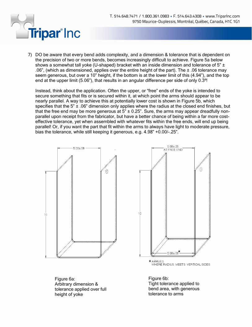
7) DO be aware that every bend adds complexity, and a dimension & tolerance that is dependent on
the precision of two or more bends, becomes increasingly difficult to achieve. Figure 5a below shows a somewhat tall yoke (U-shaped) bracket with an inside dimension and tolerance of 5” ± .06”, (which as dimensioned, applies over the entire height of the part). The ± .06 tolerance may seem generous, but over a 10” height, if the bottom is at the lower limit of this (4.94”), and the top end at the upper limit (5.06”), that results in an angular difference per side of only 0.3⁰!
Instead, think about the application. Often the upper, or “free” ends of the yoke is intended to secure something that fits or is secured within it, at which point the arms should appear to be nearly parallel. A way to achieve this at potentially lower cost is shown in Figure 5b, which specifies that the 5” ± .06” dimension only applies where the radius at the closed end finishes, but that the free end may be more generous at 5” ± 0.25”. Sure, the arms may appear dreadfully non-parallel upon receipt from the fabricator, but have a better chance of being within a far more cost-effective tolerance, yet when assembled with whatever fits within the free ends, will end up being parallel! Or, if you want the part that fit within the arms to always have light to moderate pressure, bias the tolerance, while still keeping it generous, e.g. 4.98” +0.00/-.25”.
Figure 6b: Tight tolerance applied to bend area, with generous tolerance to arms
Figure 6a: Arbitrary dimension & tolerance applied over full height of yoke

Now imagine a similar yoke, but one which has two more bends as shown in Figure 7a. Here, the upper or “free” end dimension of the yoke is determined by four bends. Achieving a tight tolerance in this case is even more difficult to achieve, and even more costly if an arbitrary tolerance is given without thought to the manufacturing difficulties involved. Apply the same strategy as explained above to keep costs down without any compromise to your overall assembly!
Figure 7a: Tight dimension & tolerance applied only to the free end opening
Figure 7b: Where possible, tighter tolerance applied to bend areas, with no tolerance to the free end opening
8) DO remember that all sheet materials have a thickness tolerance, which are also different amongst materials. For example, cold-rolled steel (CRS) and galvanized steel may be offered in

the same gauges, but they each come with different tolerances. Similarly, some materials are not bought in gauges, but in nominal thicknesses (e.g. aluminum and stainless steel). See table below. Make sure that your design, drawing, and tolerances can cope with these material tolerance variations!
Gauge HR Steel HR Tol CR Steel CR Tol Galv Steel
Galv Tol Stainless
Steel SS Tol Aluminum Alum.Tol
3 0.2391 +/-.009 0.2391 0.25 0.2294 +/-0.011
4 0.2242 +/-.009 0.2242 0.2344 0.2043 +/-0.011
5 0.2092 +/-.009 0.2092 0.2187 0.1819 +/-.009
6 0.1943 +/-.009 0.1943 0.2031 0.162 +/-.009
7 0.1793 +/-.008 0.1793 +/-.008 0.1875 +/-.007 0.1443 +/-.007
8 0.1644 +/-.008 0.1644 +/-.008 0.165 +/-.007 0.1285 +/-.007
9 0.1495 +/-.008 0.1495 +/-.008 0.1532 +/-.009 0.1562 +/-.007 0.1144 +/-.006
10 0.1345 +/-.008 0.1345 +/-.006 0.1382 +/-.009 0.1406 +/-.006 0.1019 +/-.006
11 0.1196 +/-.008 0.1196 +/-.006 0.1233 +/-.009 0.125 +/-.005 0.0907 +/-.0045
12 0.1046 +/-.008 0.1046 +/-.006 0.1084 +/-.009 0.1094 +/-.005 0.0808 +/-.0045
13 0.0897 +/-.007 0.0897 +/-.005 0.0934 +/-.008 0.0937 +/-.004 0.072 +/-.004
14 0.0747 +/-.007 0.0747 +/-.005 0.0785 +/-.008 0.0781 +/-.004 0.0641 +/-.004
15 0.0673 +/-.006 0.0673 +/-.005 0.071 +/-.006 0.0703 +/-.004 0.0571 +/-.0035
16 0.0598 +/-.006 0.0598 +/-.005 0.0635 +/-.006 0.0625 +/-.003 0.0508 +/-.0035
17 0.0538 +/-.006 0.0538 +/-.004 0.0575 +/-.005 0.0562 +/-.003 0.0453 +/-.0035
18 0.0478 +/-.005 0.0478 +/-.004 0.0516 +/-.005 0.05 +/-.003 0.0403 +/-.003
19 0.0418 +/-.004 0.0418 +/-.004 0.0456 +/-.005 0.0437 +/-.003 0.0359 +/-.003
20 0.0359 +/-.003 0.0359 +/-.003 0.0396 +/-.004 0.0375 +/-.002 0.032 +/-.0025
21 0.0329 +/-.003 0.0329 +/-.003 0.0366 +/-.004 0.0344 +/-.002 0.0285 +/-.0025
22 0.0299 +/-.003 0.0299 +/-.003 0.0336 +/-.004 0.0312 +/-.002 0.0253 +/-.002
23 0.0269 +/-.003 0.0269 +/-.003 0.0306 +/-.004 0.0281 +/-.002 0.0226 +/-.002
24 0.0239 +/-.003 0.0239 +/-.003 0.0276 +/-.004 0.025 +/-.0015
0.0201 +/-.002
25 0.0209 +/-.003 0.0209 +/-.003 0.0247 +/-.004 0.0219 +/-.0015
0.0179 +/-.002
26 0.0179 +/-.002 0.0179 +/-.002 0.0217 +/-.003 0.0187 +/-.0015
0.0159 +/- .0015
27 0.0164 +/-.002 0.0164 +/-.002 0.0202 +/-.003 0.0172 +/-.0015
0.0142 +/- .0015
28 0.0149 +/-.002 0.0149 +/-.002 0.0187 +/-.003 0.0156 +/-.0015
0.0126 +/- .0015
29 0.0135 +/-.002 0.0135 0.0172 +/-.003 0.0141 0.0113 +/- .0015
30 0.012 +/-.002 0.012 0.0157 +/-.003 0.0125 0.01 +/- .0015
31 0.0105 0.0105 0.0142 0.0109 0.0089 +/- .0015
32 0.0097 0.0097 0.0134 0.0102 0.008 +/- .0015
33 0.009 0.009 0.0094 0.0071 +/- .0015
34 0.0082 0.0082 0.0086 0.0063 +/- .0015
35 0.0075 0.0075 0.0078 0.0056 +/- .0015
36 0.0067 0.0067 0.007 -
9) DO remember that when parts are bent or formed, they are usually “wrapped” around a male die.
As a result, dimensions should be to the inside of such radii or forms, as the outside is not as controllable, and also affected by the material thickness tolerance or variations.
10) DO try to give as much latitude on bending radii as possible, as this will increase the chances that
your fabricator can find a suitable bending die within his arsenal of press break tooling. If not, you, the OEM, are going to pay for that new bending die; either up front, or it will be buried in the fabricator’s quote. For example, if you are designing with 16 GA CRS (0.06”), and have called for an inside radius of 0.12 (smartly adhering to the rule of thumb that inside radii should never be less than 1.5 times

material thickness, or preferably 2 times the material thickness), but you can live with an inside radii up to 0.18”, specify the radii as 0.18/0.12”. This increases the chances that you fabricator will have existing dies within the range. And don’t worry if your flat development was designed for a 0.12” radius. If you fabricator wishes to use a 0.18” radius, it is up to them to modify the flat development to yield the bent part. After all, what you are purchasing is generally the bent or formed part, which is what your supplier must respect.
11) DO remember that if a metal stamping or fabricated metal part is what you have designed, that by the very nature of the process, there will be slightly sharp edges and small burrs. Specifying PART SHALL BE FREE OF BURRS, or worse, DEBURRS AND BREAK ALL SHARP EDGES, will always drive up cost! Small burrs are a nature of the process, thus fabricators will often state on their quote PART SUPPLIED IN ITS AS STAMPED CONDITION. If this is an issue, it is up to the OEM to discuss this further with the incumbent supplier. If this is absolutely required, there are ways it might be achievable, but at increasing cost. Small parts that are also not subject to permanently flex upon light loads may be able to be tumbled or vibratory finished. This may soften the outer edges of the part, but depending on the deburring process and media used, it may not deburr within tight corners or small holes & cut-outs. Larger and more fragile parts may need to be run through a timesaver (part passed through a sandwich of two wide flat abrasive belts), or hand manipulated to deburr edges against an abrasive belt or wheel. However, all of these are extra steps, adds cost, and may also affect or change the surface finish in unpredictable and often non-repeatable ways. The best solution to this is to work with a reputable fabricator who will monitor all tools for wear, thus keeping burrs to a minimum.
Conclusion: Remember that relying on a drawing’s default tolerance table may save you design time, but if it results in an overtoleranced (or ill-toleranced part that may not work within your assembly), the initial savings in reduced design time, will often be wiped out on recurring part costs, for which there may be many thousand/hundreds of thousands produced over many years! Think about how you parts will ultimately be used, dimensioning and tolerancing appropriately, remembering that large tolerances do not equate to low quality. In fact, a well dimensioned and toleranced part equates to quality in that it will yield the part you need for the application; no more and no less, while having the greatest potential to save part cost. You, the OEM knows how each part is used in your assembly, thus you are best placed to give time and consideration to tolerancing. If you are unsure, share your assembly with your fabricator. One who works in your interest, and understands and applies the techniques of DFM, may have cost-saving solutions for you. Watch for Part II – Feature Design in an upcoming issue of TriparTech.
Copyright © 2022 FDOKUMEN