
MULTILEVEL CONVERTER STATCOM FAULT TOLERANCE CAPABILITY
12
INTERNATIONAL JOURNAL OF RESEARCH IN COMPUTER APPLICATIONS AND ROBOTICS www.ijrcar.com Vol.2 Issue.11, Pg.: 1-12 November 2014 K.Varalakshmi et al Page 1 INTERNATIONAL JOURNAL OF RESEARCH IN COMPUTER APPLICATIONS AND ROBOTICS ISSN 2320-7345 Multilevel Converter STATCOM Fault Tolerance Capability K.Varalakshmi 1 , Dr.R.L.Narasimham 2 Dr.G.Tulasiramdas 3 1 Associate proffersor, EEE department, TKR Engg. College, HYD, [email protected] 2 Professor, EEE department, Andhra University, [email protected] 3 Vice chancellor, JNTU-Kakinada, [email protected] Abstract Fault tolerant capability of multilevel converters in STATCOM (static synchronous compensator) has been utilized as power system controller for reactive power compensation and voltage regulation improvement. The advantages of the multilevel structure for The STATCOM are 1) Elimination of bulky transformers.2) Reduction of the output harmonic levels by Synthesizing Sinusoidal voltage 3) lower switching losses. The structure has only one disadvantage that is increased switch failure, due to the increased number of switches. A single switch failure, however, does not necessarily force an (2n + 1)- level STATCOM offline. Even with a reduced number of switches, a STATCOM can still provide a significant range of control by removing the module of the faulted switch and continuing with (2n − 1) levels. This paper introduces an approach to identify the existence of the faulted switch, and reconfigure the STATCOM. This approach is illustrated on 13 level converters STATCOM and total harmonic distortion is analyzed by using MATLAB. Keywords- Statics synchronous compensator (STATCOM), Cascaded H-Bridge, fault detection, phase shift pulse width modulation (PSPWM). I. INTRODUCTION The static synchronous compensator (STATCOM) a FACTS device, using voltage source converters has been widely accepted to improve power system operation. In bulk power systems, they are indispensable to stabilize the power system and maintain the bus voltage. Several STATCOM’s based On GTOs and zigzag transformers have been developed and put into operation within the last 10years.Typically 48 pulse consists of eight voltage source converters connected through 8zig-zag transformers are most expensive components in the system .one popular method to eliminate the bulky transformers is to use multilevel converters .The General structure of multilevel converters is to synthesize a staircase waveform, typically obtained from capacitor voltage sources [1].The advantages of cascaded H-bridge multilevel topology for The STATCOM are 1) reactive-power compensation 2) lower harmonic injection into the power system. 3) Decreased stress on the electronic components due to decreased voltages. 4) Increase of switching frequencies and the use of PWM techniques.
-
Upload
independent -
Category
Documents
-
view
1 -
download
0
Transcript of MULTILEVEL CONVERTER STATCOM FAULT TOLERANCE CAPABILITY
INTERNATIONAL JOURNAL OF RESEARCH IN COMPUTER APPLICATIONS AND ROBOTICS www.ijrcar.com
Vol.2 Issue.11, Pg.: 1-12
November 2014
K . V a r a l a k s h m i e t a l
Page 1
INTERNATIONAL JOURNAL OF
RESEARCH IN COMPUTER
APPLICATIONS AND ROBOTICS
ISSN 2320-7345
Multilevel Converter STATCOM Fault
Tolerance Capability
K.Varalakshmi
1, Dr.R.L.Narasimham
2 Dr.G.Tulasiramdas
3
1Associate proffersor, EEE department, TKR Engg. College, HYD, [email protected] 2 Professor, EEE department, Andhra University, [email protected]
3Vice chancellor, JNTU-Kakinada, [email protected]
Abstract
Fault tolerant capability of multilevel converters in STATCOM (static synchronous compensator) has been utilized
as power system controller for reactive power compensation and voltage regulation improvement. The advantages
of the multilevel structure for The STATCOM are 1) Elimination of bulky transformers.2) Reduction of the output
harmonic levels by Synthesizing Sinusoidal voltage 3) lower switching losses. The structure has only one
disadvantage that is increased switch failure, due to the increased number of switches. A single switch failure,
however, does not necessarily force an (2n + 1)- level STATCOM offline. Even with a reduced number of switches,
a STATCOM can still provide a significant range of control by removing the module of the faulted switch and
continuing with (2n − 1) levels. This paper introduces an approach to identify the existence of the faulted switch,
and reconfigure the STATCOM. This approach is illustrated on 13 level converters STATCOM and total harmonic
distortion is analyzed by using MATLAB.
Keywords- Statics synchronous compensator (STATCOM), Cascaded H-Bridge, fault detection, phase shift pulse
width modulation (PSPWM).
I. INTRODUCTION
The static synchronous compensator (STATCOM) a FACTS device, using voltage source converters has been
widely accepted to improve power system operation. In bulk power systems, they are indispensable to stabilize the
power system and maintain the bus voltage. Several STATCOM’s based On GTOs and zigzag transformers have
been developed and put into operation within the last 10years.Typically 48 pulse consists of eight voltage source
converters connected through 8zig-zag transformers are most expensive components in the system .one popular
method to eliminate the bulky transformers is to use multilevel converters .The General structure of multilevel
converters is to synthesize a staircase waveform, typically obtained from capacitor voltage sources [1].The
advantages of cascaded H-bridge multilevel topology for The STATCOM are 1) reactive-power compensation 2)
lower harmonic injection into the power system. 3) Decreased stress on the electronic components due to decreased
voltages. 4) Increase of switching frequencies and the use of PWM techniques.

INTERNATIONAL JOURNAL OF RESEARCH IN COMPUTER APPLICATIONS AND ROBOTICS www.ijrcar.com
Vol.2 Issue.11, Pg.: 1-12
November 2014
K . V a r a l a k s h m i e t a l
Page 2
Fig.1. Eleven-level cascaded multilevel STATCOM.
Various multilevel converters also readily lend themselves to a variety of PWM strategies to improve efficiency and
control [2]. After two decades, multilevel converters are still in continuous development in fields such as Static
Compensators, photo voltaic, topologies, and modulation and control techniques. All the multilevel topologies,
namely, neutral point clamped , cascade multi cell (CM), and flying capacitor, require a large amount of components
in order to distribute the voltage (and, hence, the power) among them. An associated issue related to a high number
of components is an increase in the probability of internal fault. However, most multilevel converters allow
themselves to be reconfigured in order to work in an under-rated operation mode. This paper is focused on the
thirteen levels CM converter operation after an internal fault condition has been detected, either by sensing each
power switch or using a more sophisticated method. A good characteristic of CM converters is that faulty cells can be isolated from the system by using bypass switches, which even allows the faulty cell to be replaced by a new one
without turning off the system [3]. An eleven-level cascaded multilevel STATCOM is shown in Fig.1. To synthesize
staircase waveforms this converter uses several full bridges in series as every full bridge can have three output
voltages with different switching combinations, the numbers of output voltage levels will be 2n+1 Where n is the
number of full bridges in every phase. In thirteen level converter six full bridges are used for each phase. As higher
level converters are used for high output rating power applications, a large number of power switching devices will
be used. Each of these devices is a potential failure point. Therefore, it is important to design a sophisticated control
to produce a fault tolerant STATCOM. A faulty power cell in a cascaded H-Bridge STATCOM can potentially
cause switch modules to explode leading to the fault conditions such as a short circuit or an overvoltage on the
power system resulting in an expensive down time. Subsequently, it is crucial to identify the existence and location
of the fault for it to be removed. Several fault detection methods have been proposed over the last few years.
Resistor sensing, current transformation and VCE sensing are some of the more common approaches. For example,
a method based on the output current behavior is used to identify IGBT short circuits. The primary drawback with
this approach is that the fault detection time depends on the time constant of the load. Therefore, for loads with a large RL time constant, the faulty power cell can go undetected for numerous cycles, potentially leading to circuit
damage. Another fault detection approach proposed is based on a switching frequency analysis of the output phase
voltage. This method was applied to flying capacitor converters and has not been extended to cascaded
converters.AI-based methods were proposed to extract pertinent signal features to detect faults. Sensors are used to
measure each IGBT current and to initiate switching if a fault is detected. A fault-tolerant neutral point-clamped
converter was proposed. In a reconfiguration system based on bidirectional switches has been designed for three
phase asymmetric cascaded H-bridge inverters. The fundamental output Voltage phase shifts are used to rebalance a
faulted multilevel cascade converter. In this paper, the method we propose requires only that the output dc link
voltage of each phase be measured. This measurement is typically accomplished anyway for control Purposes. If a
fault is detected, the module in which the fault occurred is then isolated and removed from service. This approach is
consistent with the modular design of cascaded converters in which the cells are designed to be interchangeable rapidly removed and replaced. Until the module is replaced, the multilevel STATCOM continues to operate with
slightly decreased, but still acceptable, performance. This approach offers the following advantages:
• No additional sensing requirements.
• Additional hardware is limited to two by pass switches per Module.
• is consistent with the modular approach of cascaded
INTERNATIONAL JOURNAL OF RESEARCH IN COMPUTER APPLICATIONS AND ROBOTICS www.ijrcar.com
Vol.2 Issue.11, Pg.: 1-12
November 2014
K . V a r a l a k s h m i e t a l
Page 3
Multi level Converters. And the dynamic performance and THD of the STATCOM is not significantly impacted.
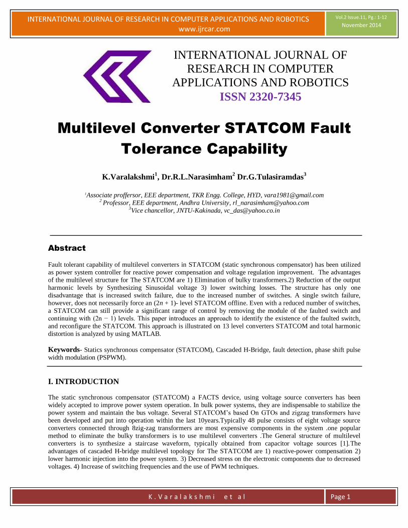
Fig.2. (a) Carrier and reference waveform for PSPWM. (b) Output waveform.
II. CASCADED MULTILEVEL STATCOM
A cascaded multilevel STATCOM contains several H-bridges in series to synthesize a staircase waveform. The
inverter legs are identical and are therefore modular. In the eleven-level STATCOM, each leg has five H-bridges.

INTERNATIONAL JOURNAL OF RESEARCH IN COMPUTER APPLICATIONS AND ROBOTICS www.ijrcar.com
Vol.2 Issue.11, Pg.: 1-12
November 2014
K . V a r a l a k s h m i e t a l
Page 4
Since each full bridge generates three different level voltages (V, 0,−V ) under different switching states, the number
of output voltage levels will be thirteen. A multilevel configuration offers several advantages over other Converter
types [2]. 1) It is better suited for high-voltage, high-power applications than the conventional converters since the
currents and voltages across the individual switching devices are smaller. 2) It generates a multistep staircase
voltage waveform approaching a more sinusoidal output voltage by increasing the number of levels. 3) It has better
dc voltage balancing, since each bridge has its own dc source. To achieve a high-quality output voltage waveform,
the voltages across all of the dc capacitors should maintain a constant value. Variations in load cause the dc
capacitors to charge and discharge unevenly leading to different voltages in each leg of each phase. However,
because of the redundancy in switching states, there is frequently more than one state that can synthesize any given
voltage level. Therefore, there exists a “best” state among all the possible states that produces the most balanced
voltages. Since there are multiple possible switching states that can be used to synthesize a given voltage level, the
particular switching topology is chosen such that the capacitors with the lowest voltages are charged or conversely,
the capacitors with the highest voltages are discharged. This redundant state selection approach is used to maintain
the total dc link voltage to a near constant value and each individual cell capacitor within a tight bound .Different
pulse width modulation (PWM) techniques have been used to obtain the multilevel converter output voltage. One
common PWM approach is the phase shift PWM (PSPWM) switching concept.
III. CARRIER BASED MODULATION SCHEMES
Most carrier-based PWM schemes for diode-clamped inverters derive from the carrier disposition strategy. For an N
-level diode-clamped inverter, this strategy arranges N-1 triangular carriers with the same frequency and amplitude
so that they fully occupy contiguous bands over the range +Vdc to -Vdc. A single sinusoidal reference is then
compared with each carrier to determine the switched output voltages for the converter. Three alternative carrier
disposition PWM strategies are commonly referenced, viz:1) Alternative phase opposition disposition (APOD),
where each carrier is phase shifted by 180 from its adjacent carrier.2) Phase opposition disposition (POD), where
thecarriers above the sinusoidal reference zero point are 180 out of phase with those below the zero point.3) Phase
disposition (PD), where all carriers are in phase. For the cascaded inverter, phase-shifted carrier PWM (PSPWM) is
the most common strategy with an improved harmonic performance [4]. The PSPWM strategy causes cancellation
of all carrier and associated sideband harmonics up to the (N −1) the carrier group for an N-level converter. Each
carrier signal is phase shifted by
Δφ =2π/n
Where n is the number of cells in each phase. Fig. 2 illustrates the carrier and reference waveforms for a phase leg of
the eleven-level STATCOM. In this figure, the carrier frequency has been decreased for better clarity. Normally, the
carrier frequency for PWM is in the range of 1–10 kHz [2].
IV. PROPOSED SYSTEM
In this paper thirteen level converter is used instead of eleven level converter. In thirteen level converter six full
bridges are used for each phase. Number of cells increases means output voltage of the STATCOM increases. So the
advantages of this converter are:
1) Improve the line active power.
2) Total harmonic distortion (THD) will be reduced.
as oscillations in the output wave form are reduced.
3) Modulation gain will be decreased.

INTERNATIONAL JOURNAL OF RESEARCH IN COMPUTER APPLICATIONS AND ROBOTICS www.ijrcar.com
Vol.2 Issue.11, Pg.: 1-12
November 2014
K . V a r a l a k s h m i e t a l
Page 5
Fig.4.Simplified thirteen level cascaded STATCOM.
V. FAULT ANALYSIS FOR THE MULTILEVEL STATCOM
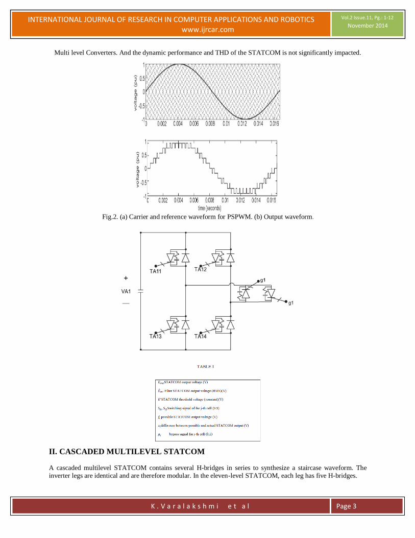
A converter cell block, as shown in Fig. 3, can experience several types of faults. Each switch in the cell can fail in
an open or closed state. The closed state is the most severe failure since it may lead to shoot through and short
circuit the entire cell. An open circuit can be avoided by using a proper gate circuit to control the gate current of the
switch during the failure. If a short circuit failure occurs, the capacitors will rapidly discharge through the
conducting switch pair if no protective action is taken. Hence, the counterpart switch to the failed switch must be
quickly turned off to avoid system collapse due to a sharp current surge. Nomenclature for the proposed method is given in Table I.
The staircase voltage waveform shown in Fig. 2 is synthesized by combining the voltages of the various cells into
the desired level of output voltage. At the middle levels of the voltage waveform, due to the switching state
redundancy, there are more than one set of switching combinations that may be used to construct the desired voltage
level. Therefore, by varying the switching patterns, the loss of any individual cell will not significantly impact the
middle voltages of the output voltage. However, the peak voltages require that all cells contribute to the voltage.
Therefore, the short circuit failure of any one cell will lead to the loss of the first and (2n + 1) output levels and
cause degradation in the ability of the STATCOM to produce the full output voltage level [2]. Consider the
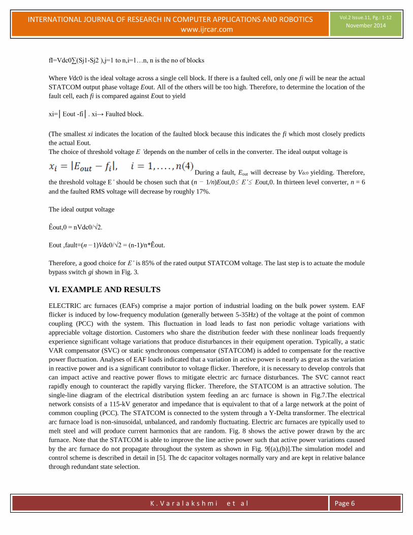
simplified thirteen-level converter shown in Fig. 4. The process for identifying and removing the faulty cell block is
summarized in Fig.
5. The input to the detection algorithm is ˆEout for each phase, where ˆEout is the STATCOM filtered RMS output
voltage. If the STATCOM RMS output voltage drops below a preset threshold value (E’), then, a fault is known to
have occurred (see Fig.6). Once a fault has been detected to have occurred, then, the next step is to identify the
faulty cell. By utilizing the switching signals in each converter cell, (i.e., S1 and S2), it is possible to calculate all of the possible voltages that can be produced at any given instant as illustrated in Table II .
Thus, the output voltage of a cell
(1) and since the cells of the STATCOM are serially connected ,the
total output voltage per phase is
Where n is the number of blocks. When there is a fault in the
multilevel converter, the capacitor at the faulty block will rapidly discharge. This discharge results in a phase shift in
the output ac voltage as well as a change in amplitude of voltage. The set of all possible phase fault voltages for
thirteen-level converter is given by
f1=vdc0(S21-S22+S31-S32+S41-S42+S51-52+S61-S62).
f2…f6 also as same as above formula.
INTERNATIONAL JOURNAL OF RESEARCH IN COMPUTER APPLICATIONS AND ROBOTICS www.ijrcar.com
Vol.2 Issue.11, Pg.: 1-12
November 2014
K . V a r a l a k s h m i e t a l
Page 6
fI=Vdc0∑(Sj1-Sj2 ),j=1 to n,i=1…n, n is the no of blocks
Where Vdc0 is the ideal voltage across a single cell block. If there is a faulted cell, only one fi will be near the actual
STATCOM output phase voltage Eout. All of the others will be too high. Therefore, to determine the location of the
fault cell, each fi is compared against Eout to yield
xi=│Eout -fi│. xi→ Faulted block.
(The smallest xi indicates the location of the faulted block because this indicates the fi which most closely predicts
the actual Eout.
The choice of threshold voltage E ’depends on the number of cells in the converter. The ideal output voltage is
During a fault, Eout will decrease by Vdc0 yielding. Therefore,
the threshold voltage E’ should be chosen such that (n − 1/n)Eout,0≤ E’≤ Eout,0. In thirteen level converter, n = 6
and the faulted RMS voltage will decrease by roughly 17%.
The ideal output voltage
Êout,0 = nVdc0/√2.
Eout ,fault=(n −1)Vdc0/√2 = (n-1)/n*Êout.
Therefore, a good choice for E’ is 85% of the rated output STATCOM voltage. The last step is to actuate the module
bypass switch gi shown in Fig. 3.
VI. EXAMPLE AND RESULTS
ELECTRIC arc furnaces (EAFs) comprise a major portion of industrial loading on the bulk power system. EAF
flicker is induced by low-frequency modulation (generally between 5-35Hz) of the voltage at the point of common
coupling (PCC) with the system. This fluctuation in load leads to fast non periodic voltage variations with
appreciable voltage distortion. Customers who share the distribution feeder with these nonlinear loads frequently
experience significant voltage variations that produce disturbances in their equipment operation. Typically, a static
VAR compensator (SVC) or static synchronous compensator (STATCOM) is added to compensate for the reactive
power fluctuation. Analyses of EAF loads indicated that a variation in active power is nearly as great as the variation
in reactive power and is a significant contributor to voltage flicker. Therefore, it is necessary to develop controls that
can impact active and reactive power flows to mitigate electric arc furnace disturbances. The SVC cannot react
rapidly enough to counteract the rapidly varying flicker. Therefore, the STATCOM is an attractive solution. The
single-line diagram of the electrical distribution system feeding an arc furnace is shown in Fig.7.The electrical
network consists of a 115-kV generator and impedance that is equivalent to that of a large network at the point of
common coupling (PCC). The STATCOM is connected to the system through a Y-Delta transformer. The electrical
arc furnace load is non-sinusoidal, unbalanced, and randomly fluctuating. Electric arc furnaces are typically used to
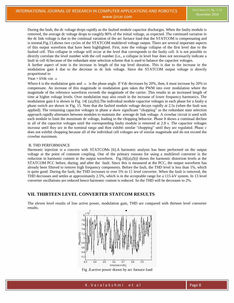
melt steel and will produce current harmonics that are random. Fig. 8 shows the active power drawn by the arc
furnace. Note that the STATCOM is able to improve the line active power such that active power variations caused
by the arc furnace do not propagate throughout the system as shown in Fig. 9[(a),(b)].The simulation model and
control scheme is described in detail in [5]. The dc capacitor voltages normally vary and are kept in relative balance
through redundant state selection.
INTERNATIONAL JOURNAL OF RESEARCH IN COMPUTER APPLICATIONS AND ROBOTICS www.ijrcar.com
Vol.2 Issue.11, Pg.: 1-12
November 2014
K . V a r a l a k s h m i e t a l
Page 7
TABLE II
SWITCHING STATE AND OUTPUT VOLTAGE OF AN HBRIDGE
A. DYNAMIC PERFORMANCE
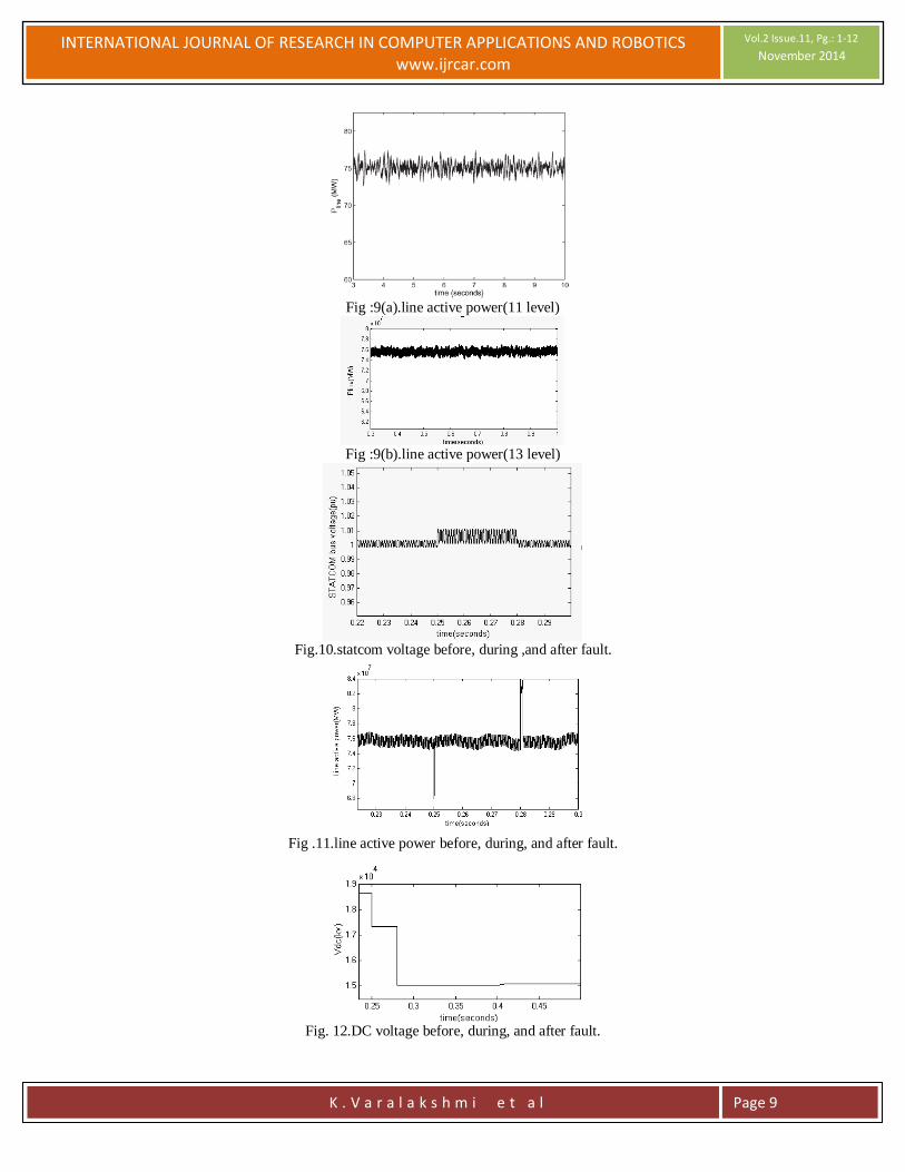
To test the proposed fault detection and mitigation approach, a faulty switch was initiated at 2.5 s. Within 300 ms,
the fault has been detected, the module removed, and the STATCOM restored to steady-state operation. This fault
duration is longer than is necessary. The fault was intentionally left on to better illustrate its effect on the system and
removal. The STATCOM bus voltage and line active powers are shown before the fault, during, and after the faulty
module is removed (Figs. 10 and 11). Note that both the bus voltage and line active power are adversely affected
during the fault. In both cases, the high frequency oscillations are increased. Once the faulty module is removed, the system returns to its pre fault behavior. There is a small induced low-frequency oscillation that can be observed in
the line active power, but this is rapidly damped by the STATCOM’s control. The average dc link voltage before,
during, and after the fault is shown in Fig. 12.
INTERNATIONAL JOURNAL OF RESEARCH IN COMPUTER APPLICATIONS AND ROBOTICS www.ijrcar.com
Vol.2 Issue.11, Pg.: 1-12
November 2014
K . V a r a l a k s h m i e t a l
Page 8
During the fault, the dc voltage drops rapidly as the faulted module capacitor discharges. When the faulty module is
removed, the average dc voltage drops to roughly 80% of the initial voltage, as expected. The continued variation in
the dc link voltage is due to the continual variation of the arc furnace load that the STATCOM is compensating and
is normal.Fig.13.shows two cycles of the STATCOM multilevel voltage output. There are several important aspects
of this output waveform that have been highlighted. First, note the voltage collapse of the first level due to the
faulted cell. This collapse in voltage will occur at the level that corresponds to the faulty cell. It is not possible to directly correlate the level number with the cell number (i.e., a collapse in level four does not necessarily indicate a
fault in cell 4) because of the redundant state selection scheme that is used to balance the capacitor voltages.
A further aspect of note is the increase in length of the top level duration. This is due to the increase in the
modulation gain k due to the decrease in dc link voltage. Since the STATCOM output voltage is directly
proportional to
Vstat = kVdc cos α Where k is the modulation gain and α is the phase angle. If Vdc decreases by 20%, then, k must increase by 20% to
compensate. An increase of this magnitude in modulation gain takes the PWM into over modulation where the
magnitude of the reference waveform exceeds the magnitude of the carrier. This results in an increased length of
time at higher voltage levels. Over modulation may also result in the increase of lower frequency harmonics. The
modulation gain k is shown in Fig. 14[ (a),(b)].The individual module capacitor voltages in each phase for a faulty a
phase switch are shown in Fig. 15. Note that the faulted module voltage decays rapidly at 2.5s (when the fault was
applied). The remaining capacitor voltages in phase a show significant “chopping” as the redundant state selection
approach rapidly alternates between modules to maintain the average dc link voltage. A crowbar circuit is used with each module to limit the maximum dc voltage, leading to the chopping behavior. Phase b shows a continual decline
in all of the capacitor voltages until the corresponding faulty module is removed at 2.8 s. The capacitor voltages
increase until they are in the nominal range and then exhibit similar “chopping” until they are regulated. Phase c
does not exhibit chopping because all of the individual cell voltages are of similar magnitude and do not exceed the
crowbar maximum.
B. THD PERFORMANCE
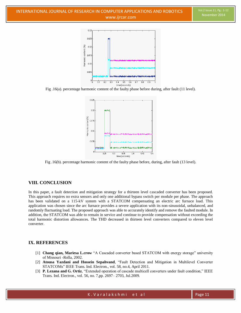
Harmonic injection is a concern with STATCOMs [6].A harmonic analysis has been performed on the output
voltage at the point of common coupling. One of the primary reasons for using a multilevel converter is the
reduction in harmonic content in the output waveform. Fig.16[(a),(b)] shows the harmonic distortion levels at the
STATCOM PCC before, during, and after the fault. Since this is measured at the PCC, the output waveform has
already been filtered to remove high frequency components. Before the fault, the THD level is less than 1%, which is quite good. During the fault, the THD increases to over 5% in 11 level converter. When the fault is removed, the
THD decreases and settles at approximately 2.5%, which is in the acceptable range for a 115-kV system. In 13 level
converter oscillations are reduced hence harmonic content is reduced. So the THD will be decreases to 2%.
VII. THIRTEEN LEVEL CONVERTER STATCOM RESULTS The eleven level results of line active power, modulation gain, THD are compared with thirteen level converter
results.
Fig .8.active power drawn by arc furnace load
INTERNATIONAL JOURNAL OF RESEARCH IN COMPUTER APPLICATIONS AND ROBOTICS www.ijrcar.com
Vol.2 Issue.11, Pg.: 1-12
November 2014
K . V a r a l a k s h m i e t a l
Page 9
Fig :9(a).line active power(11 level)
Fig :9(b).line active power(13 level)
Fig.10.statcom voltage before, during ,and after fault.
Fig .11.line active power before, during, and after fault.
Fig. 12.DC voltage before, during, and after fault.

INTERNATIONAL JOURNAL OF RESEARCH IN COMPUTER APPLICATIONS AND ROBOTICS www.ijrcar.com
Vol.2 Issue.11, Pg.: 1-12
November 2014
K . V a r a l a k s h m i e t a l
Page 10
Fig. 13. Converter output with faulted cell.
Fig (14a). Modulation gain k before, during, and after fault.
Fig (14b). Modulation gain k before, during, and after fault.
Fig.15. Individual module capacitor voltages before, during, and after fault.
INTERNATIONAL JOURNAL OF RESEARCH IN COMPUTER APPLICATIONS AND ROBOTICS www.ijrcar.com
Vol.2 Issue.11, Pg.: 1-12
November 2014
K . V a r a l a k s h m i e t a l
Page 11
Fig .16(a). percentage harmonic content of the faulty phase before during, after fault (11 level).
Fig .16(b). percentage harmonic content of the faulty phase before, during, after fault (13 level).
VIII. CONCLUSION
In this paper, a fault detection and mitigation strategy for a thirteen level cascaded converter has been proposed.
This approach requires no extra sensors and only one additional bypass switch per module per phase. The approach
has been validated on a 115-kV system with a STATCOM compensating an electric arc furnace load. This
application was chosen since the arc furnace provides a severe application with its non-sinusoidal, unbalanced, and
randomly fluctuating load. The proposed approach was able to accurately identify and remove the faulted module. In
addition, the STATCOM was able to remain in service and continue to provide compensation without exceeding the
total harmonic distortion allowances. The THD decreased in thirteen level converters compared to eleven level converter.
IX. REFERENCES
[1] Chang qian, Mariesa L.crow “A Cascaded converter based STATCOM with energy storage” university
of Missouri -Rolla, 2002.
[2] Atousa Yazdani and Hossein Sepahvand, “Fault Detection and Mitigation in Multilevel Converter
STATCOMs” IEEE Trans. Ind. Electron., vol. 58, no.4, April 2011.
[3] P. Lezana and G. Ortiz, “Extended operation of cascade multicell converters under fault condition,” IEEE
Trans. Ind. Electron., vol. 56, no. 7,pp. 2697– 2703, Jul.2009.

INTERNATIONAL JOURNAL OF RESEARCH IN COMPUTER APPLICATIONS AND ROBOTICS www.ijrcar.com
Vol.2 Issue.11, Pg.: 1-12
November 2014
K . V a r a l a k s h m i e t a l
Page 12
[4] B. McGrath and D. Holmes, “Multicarrier PWM strategies for multilevel converters,” IEEE Trans. Ind.
Electron., vol. 49, no. 4, pp. 858–867, Aug. 2002.
[5] A. Yazdani, M. Crow, and J. Guo, “An improved nonlinear STATCOM control for electric arc furnace
voltage flicker mitigation,” IEEE Trans.Power Del., vol. 24, no. 4, pp. 2284–2290, Oct. 2009.
[6] B.-S. Chen and Y.-Y. Hsu, “A minimal harmonic controller for a STATCOM,” IEEE Trans. Ind.
Electron., vol. 55, no. 2, pp. 655–664,Feb. 2008. [7] P. Barriuso, J. Dixon, P. Flores, and L. Morán, “Fault-tolerant reconfiguration system for asymmetric
multilevel converters using bidirectional power switches,” IEEE Trans. Ind. Electron., vol. 56, no. 4, pp.
1300–1306, Apr.2009.
[8] F. Z. Peng, J. S. Lai,W. McKeever, and J.VanCoevering, “A multilevel voltage source inverter with
separate dc sources for static VAR generation,” IEEE Trans. Ind. Appl., vol. 32, no. 5, pp. 1130–1138, Sep.
1996.
[9] K. A. Corzine, M. W. Wielebski, F. Z. Peng, and J. Wang, “Control of cascaded multilevel inverters,”
IEEE Trans. Power Electron., vol. 19,no. 3, pp. 732– 738, May 2004.