
Optimal Design and Control of MMC STATCOM for ... - MDPI
29
applied sciences Article Optimal Design and Control of MMC STATCOM for Improving Power Quality Indicators Ahmed A. Zaki Diab 2,3, * , Terad Ebraheem 4 , Raseel Aljendy 5, * , Hamdy M. Sultan 2,5 and Ziad M. Ali 1,6 1 College of Engineering at Wadi Addawaser, Prince Sattam bin Abdulaziz University, Wadi Aldawaser 11991, Saudi Arabia; [email protected] 2 Electrical Engineering Department, Faculty of Engineering, Minia University, Minia 61111, Egypt; [email protected] 3 Department of Electrical Engineering, Kyushu University, Fukuoka 819-0395, Japan 4 Electrical Engineering Department, Faculty of Engineering, Tishreen University, Latakia 2237, Syria; [email protected] 5 Electrical Power Systems Department, Moscow Power Engineering Institute “MPEI”, Moscow 111250, Russia 6 Electrical Engineering Department, Aswan Faculty of Engineering, Aswan University, Aswan 81542, Egypt * Correspondence: [email protected] (A.A.Z.D.); [email protected] (R.A.); Tel.: +2-01021777925 (A.A.Z.D.) Received: 9 March 2020; Accepted: 30 March 2020; Published: 4 April 2020 Abstract: In recent years, modular multilevel converters (MMC) are becoming popular in the distribution and transmission of electrical systems. The multilevel converter suffers from circulating current within the converter that increases the conduction loss of switches and increases the thermal stress on the capacitors and switches’ IGBTs. One of the main solutions to control the circulating current is to keep the capacitor voltage balanced in the MMC. In this paper, a new hybrid control algorithm for the cascaded modular multilevel converter is presented. The Harris hawk’s optimization (HHO) and Atom search optimization (ASO) are used to optimally design the controller of the hybrid MMC. The proposed structure of modular multilevel inverters allows effective operation, a low level of harmonic distortion in the absence of output voltage filters, a low switching frequency, and excellent flexibility to achieve the requirements of any voltage level. The effectiveness of the proposed controller and the multilevel converter has been verified through testing with the application of the MMC-static synchronous compensator (STATCOM). The stability of the voltage capacitors was monitored with balanced and unbalanced loads on the studied network. Keywords: modular multilevel converter; STATCOM; optimization; harmonics; Harris Hawk’s optimization; Atom search optimization 1. Introduction Recently, with the increased popularity and application of power electronic devices in modern industries, some large electrical loads such as from an AC traction system (single-phase), electric furnaces and modern technologies based on high-tech microprocessors in renewable energy applications cause increasing power quality (PQ) problems [1,2]. Power quality problems appear in electric utility as increased harmonic distortions, phase imbalances and low power factors. Electric devices based on power electronics present themselves as non-linear loads, which are characterized as sources of harmonics in the power system. The harmonic currents cause an increase in the RMS value of the current and let the neutral current make circulations in the electric distribution system. The capacity of the distribution system and power losses are affected by the presence of harmonics [2,3]. Appl. Sci. 2020, 10, 2490; doi:10.3390/app10072490 www.mdpi.com/journal/applsci
-
Upload
khangminh22 -
Category
Documents
-
view
1 -
download
0
Transcript of Optimal Design and Control of MMC STATCOM for ... - MDPI
applied sciences
Article
Optimal Design and Control of MMC STATCOM forImproving Power Quality Indicators
Ahmed A. Zaki Diab 2,3,* , Terad Ebraheem 4, Raseel Aljendy 5,* , Hamdy M. Sultan 2,5 andZiad M. Ali 1,6
1 College of Engineering at Wadi Addawaser, Prince Sattam bin Abdulaziz University,Wadi Aldawaser 11991, Saudi Arabia; [email protected]
2 Electrical Engineering Department, Faculty of Engineering, Minia University, Minia 61111, Egypt;[email protected]
3 Department of Electrical Engineering, Kyushu University, Fukuoka 819-0395, Japan4 Electrical Engineering Department, Faculty of Engineering, Tishreen University, Latakia 2237, Syria;
[email protected] Electrical Power Systems Department, Moscow Power Engineering Institute “MPEI”,
Moscow 111250, Russia6 Electrical Engineering Department, Aswan Faculty of Engineering, Aswan University, Aswan 81542, Egypt* Correspondence: [email protected] (A.A.Z.D.); [email protected] (R.A.);
Tel.: +2-01021777925 (A.A.Z.D.)
Received: 9 March 2020; Accepted: 30 March 2020; Published: 4 April 2020�����������������
Abstract: In recent years, modular multilevel converters (MMC) are becoming popular in thedistribution and transmission of electrical systems. The multilevel converter suffers from circulatingcurrent within the converter that increases the conduction loss of switches and increases the thermalstress on the capacitors and switches’ IGBTs. One of the main solutions to control the circulatingcurrent is to keep the capacitor voltage balanced in the MMC. In this paper, a new hybrid controlalgorithm for the cascaded modular multilevel converter is presented. The Harris hawk’s optimization(HHO) and Atom search optimization (ASO) are used to optimally design the controller of the hybridMMC. The proposed structure of modular multilevel inverters allows effective operation, a lowlevel of harmonic distortion in the absence of output voltage filters, a low switching frequency, andexcellent flexibility to achieve the requirements of any voltage level. The effectiveness of the proposedcontroller and the multilevel converter has been verified through testing with the application ofthe MMC-static synchronous compensator (STATCOM). The stability of the voltage capacitors wasmonitored with balanced and unbalanced loads on the studied network.
Keywords: modular multilevel converter; STATCOM; optimization; harmonics; Harris Hawk’soptimization; Atom search optimization
1. Introduction
Recently, with the increased popularity and application of power electronic devices in modernindustries, some large electrical loads such as from an AC traction system (single-phase), electricfurnaces and modern technologies based on high-tech microprocessors in renewable energy applicationscause increasing power quality (PQ) problems [1,2]. Power quality problems appear in electric utilityas increased harmonic distortions, phase imbalances and low power factors. Electric devices basedon power electronics present themselves as non-linear loads, which are characterized as sources ofharmonics in the power system. The harmonic currents cause an increase in the RMS value of thecurrent and let the neutral current make circulations in the electric distribution system. The capacity ofthe distribution system and power losses are affected by the presence of harmonics [2,3].
Appl. Sci. 2020, 10, 2490; doi:10.3390/app10072490 www.mdpi.com/journal/applsci
Appl. Sci. 2020, 10, 2490 2 of 29
The effects of nonlinear unbalanced loads on the performance of the power system is an importantissue for the power system operators and attracts the interest of many researchers. Many researchpapers have proposed different techniques and optimization algorithms to improve power qualityindicators in the presence of nonlinear and/or unbalanced loads [4]. The static synchronous compensator(STATCOM) is one of the FACTS devices that introduces an efficient and flexible solution for powerquality improvement and disturbance mitigation [5–7]. The practical circuit of the STATCOM usuallyincludes two-level voltage source converters (VSC), and a line-frequency transformer is adopted forthe enhancement of its voltage and current ratings; however, it results in the heavy, unreliable andexpensive design of the compensator [5,6].
The multilevel converters-based STATCOM has received considerable attention from researchersdue to its higher capacity that makes it reliable for application in medium- or high-voltage high gridsin the absence of line-frequency transformers. Since 1975, the concept of the multilevel converter hasbeen introduced [8]. The multilevel term began with the third-level topology [8,9]. Subsequently, manymultilevel converter topologies were developed [10–19]. However, the basic concept of the multilevelconverter is the use of a series of semiconductor power switches with several low DC voltage sourcesto conduct energy conversion and obtain higher energy. The topology of the multilevel converters hassucceeded in addressing some of the main problems in the traditional converters [10–19]. The mostimportant of these problems are the problems of power quality, especially the voltage and currentharmonics [20–23]. As the number of converter levels increases, the output voltage signal will beas good and as close as possible to the desired waveform [9–19]. But of course, advanced controltechniques are needed to improve the performance of multilevel converters and optimize the workflow.
Three major multilevel converters have been applied in high- and medium-power applications,such as the neutral-point clamped multilevel converter (NPCMC), the flying capacitor multilevelconverter (FCMC) and the cascaded H-bridge multilevel converter (CHBMC) [8,9]. The majordisadvantage of the NPCMC is the inherent voltage imbalance problems, which require an extraauxiliary compensation circuit [8,9]. As for FCMC, besides the need for highly expensive flyingcapacitors, mainly at low carrier frequencies, this type of multilevel converter is not suitable for thoseapplications with 90◦ leading or lagging currents. Moreover, for both topologies, as the voltage levelhas to be increased in high power applications, an increase in the size of the capacitors or in the climbingdiodes is required, which makes the control circuit and converter structure more complex. Comparedwith the previously explained two former topologies, CHBMC requires fewer components in the circuitdesign, which makes it convenient for physical layout and packaging. The major disadvantage ofCHBMC is that it cannot perform properly under imbalanced conditions without feeding from isolatedDC sources supplied from multi-winding transforms, which gives rise to the same problems associatedwith the use of the line-frequency transformer [8,9].
To overcome the previously mentioned problems, a new modular multilevel converter-basedSTATCOM (MMC STATCOM) is recommended for medium and high voltage applications. The MMCSTATCOM is characterized by its availability, compact and modular construction, generation of leastharmonics, etc. Moreover, the MMC STATCOM is able to exchange both active and reactive power viathe common DC-bus. Accordingly, the active power, which is redistributed in the internal circuits, isutilized for the purpose of negative sequence balance. Consequently, the MMC STATCOM can operateunder three-phase imbalance without any intermission.
In this paper, an optimization problem is introduced for the optimal design of the multilevelconverter and for determining the optimal parameters of the DC voltage controller. The minimizationof total harmonic distortion (THD) in the power system under consideration is introduced as theobjective function while keeping the ripple voltage within the allowable ranges and obtaining minimumcirculating current. Novel optimization algorithms, namely Atom Search Optimization (ASO) andHarris Hawk optimization (HHO) that have not been reported in the literature for tackling theaforementioned problem of optimization of the values of the capacitors of the MMC STATCOM havebeen applied. Moreover, to ensure the effectiveness of the proposed optimization techniques, the
Appl. Sci. 2020, 10, 2490 3 of 29
results obtained from the application of these methods have been tested under two different casestudies, nonlinear load and three-phase imbalance.
The paper is organized as follows: in Section 2, a brief review of MMC topologies is introducedin detail; Section 3 introduces the Model of the Modular Multilevel Converter (MMC); the ModularMultilevel Converter-based STATCOM (MMC STATCOM) is introduced in Section 4; Section 5 presentsthe problem formulation; Section 6 presents the Harris hawk’s optimization (HHO) and atom algorithmin detail; the result simulation presents in Section 7; and the conclusion is stated in Section 8.
2. A Brief Review of MMC Topologies
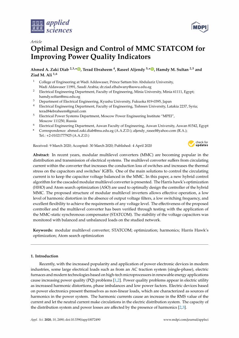
There are many topologies of the MMC. A comprehensive comparison among these topologies ispresented in Table 1 [24,25].
Table 1. Comprehensive comparison between Modular Multilevel Converter (MMC) topologies.
Topology Configuration Sub-Modules (SMs) Remarks
Single-Star BridgeCell (SSBC)
Appl. Sci. 2020, 10, x FOR PEER REVIEW 3 of 34
have been applied. Moreover, to ensure the effectiveness of the proposed optimization techniques, the results obtained from the application of these methods have been tested under two different case studies, nonlinear load and three-phase imbalance.
The paper is organized as follows: in Section 2, a brief review of MMC topologies is introduced in detail; Section 3 introduces the Model of the Modular Multilevel Converter (MMC); the Modular Multilevel Converter-based STATCOM (MMC STATCOM) is introduced in Section 4; Section 5 presents the problem formulation; Section 6 presents the Harris hawk’s optimization (HHO) and atom algorithm in detail; the result simulation presents in Section 7; and the conclusion is stated in Section 8.
2. A Brief Review of MMC Topologies
There are many topologies of the MMC. A comprehensive comparison among these topologies is presented in Table 1 [24,25].
Table 1. Comprehensive comparison between Modular Multilevel Converter (MMC) topologies.
Topology Configuration Sub-modules (SMs) Remarks
Single-Star Bridge Cell
(SSBC)
Full-bridge SM
1. No circulating currents 2. The balance of the voltage during abnormal operating conditions is limited by the rating of the devices 3. No communal for STATCOM
Single-Delta Bridge Cell
(SDBC)
Full-bridge SM
1. Circulating current 2. STATCOM applications 3. Smaller energy storage 4. Lower losses 5. Commonly used for compensation of positive sequence components 6. Susceptible to unbalanced voltage conditions
Double-Star Chopper
Cell (DSCC)
Half-bridge SM
1. Circulating current 2. STATCOM applications 3. Large energy storage 4. Low power losses 5. Excellent presentation for STATCOM
Full-bridge SM
Appl. Sci. 2020, 10, x FOR PEER REVIEW 3 of 34
have been applied. Moreover, to ensure the effectiveness of the proposed optimization techniques, the results obtained from the application of these methods have been tested under two different case studies, nonlinear load and three-phase imbalance.
The paper is organized as follows: in Section 2, a brief review of MMC topologies is introduced in detail; Section 3 introduces the Model of the Modular Multilevel Converter (MMC); the Modular Multilevel Converter-based STATCOM (MMC STATCOM) is introduced in Section 4; Section 5 presents the problem formulation; Section 6 presents the Harris hawk’s optimization (HHO) and atom algorithm in detail; the result simulation presents in Section 7; and the conclusion is stated in Section 8.
2. A Brief Review of MMC Topologies
There are many topologies of the MMC. A comprehensive comparison among these topologies is presented in Table 1 [24,25].
Table 1. Comprehensive comparison between Modular Multilevel Converter (MMC) topologies.
Topology Configuration Sub-modules (SMs) Remarks
Single-Star Bridge Cell
(SSBC)
Full-bridge SM
1. No circulating currents 2. The balance of the voltage during abnormal operating conditions is limited by the rating of the devices 3. No communal for STATCOM
Single-Delta Bridge Cell
(SDBC)
Full-bridge SM
1. Circulating current 2. STATCOM applications 3. Smaller energy storage 4. Lower losses 5. Commonly used for compensation of positive sequence components 6. Susceptible to unbalanced voltage conditions
Double-Star Chopper
Cell (DSCC)
Half-bridge SM
1. Circulating current 2. STATCOM applications 3. Large energy storage 4. Low power losses 5. Excellent presentation for STATCOM
1. No circulating currents2. The balance of the voltage during
abnormal operating conditions islimited by the rating of the devices
3. No communal for STATCOM
Single-Delta BridgeCell
(SDBC)
Appl. Sci. 2020, 10, x FOR PEER REVIEW 3 of 34
have been applied. Moreover, to ensure the effectiveness of the proposed optimization techniques, the results obtained from the application of these methods have been tested under two different case studies, nonlinear load and three-phase imbalance.
The paper is organized as follows: in Section 2, a brief review of MMC topologies is introduced in detail; Section 3 introduces the Model of the Modular Multilevel Converter (MMC); the Modular Multilevel Converter-based STATCOM (MMC STATCOM) is introduced in Section 4; Section 5 presents the problem formulation; Section 6 presents the Harris hawk’s optimization (HHO) and atom algorithm in detail; the result simulation presents in Section 7; and the conclusion is stated in Section 8.
2. A Brief Review of MMC Topologies
There are many topologies of the MMC. A comprehensive comparison among these topologies is presented in Table 1 [24,25].
Table 1. Comprehensive comparison between Modular Multilevel Converter (MMC) topologies.
Topology Configuration Sub-modules (SMs) Remarks
Single-Star Bridge Cell
(SSBC)
Full-bridge SM
1. No circulating currents 2. The balance of the voltage during abnormal operating conditions is limited by the rating of the devices 3. No communal for STATCOM
Single-Delta Bridge Cell
(SDBC)
Full-bridge SM
1. Circulating current 2. STATCOM applications 3. Smaller energy storage 4. Lower losses 5. Commonly used for compensation of positive sequence components 6. Susceptible to unbalanced voltage conditions
Double-Star Chopper
Cell (DSCC)
Half-bridge SM
1. Circulating current 2. STATCOM applications 3. Large energy storage 4. Low power losses 5. Excellent presentation for STATCOM
Full-bridge SM
Appl. Sci. 2020, 10, x FOR PEER REVIEW 3 of 34
have been applied. Moreover, to ensure the effectiveness of the proposed optimization techniques, the results obtained from the application of these methods have been tested under two different case studies, nonlinear load and three-phase imbalance.
The paper is organized as follows: in Section 2, a brief review of MMC topologies is introduced in detail; Section 3 introduces the Model of the Modular Multilevel Converter (MMC); the Modular Multilevel Converter-based STATCOM (MMC STATCOM) is introduced in Section 4; Section 5 presents the problem formulation; Section 6 presents the Harris hawk’s optimization (HHO) and atom algorithm in detail; the result simulation presents in Section 7; and the conclusion is stated in Section 8.
2. A Brief Review of MMC Topologies
There are many topologies of the MMC. A comprehensive comparison among these topologies is presented in Table 1 [24,25].
Table 1. Comprehensive comparison between Modular Multilevel Converter (MMC) topologies.
Topology Configuration Sub-modules (SMs) Remarks
Single-Star Bridge Cell
(SSBC)
Full-bridge SM
1. No circulating currents 2. The balance of the voltage during abnormal operating conditions is limited by the rating of the devices 3. No communal for STATCOM
Single-Delta Bridge Cell
(SDBC)
Full-bridge SM
1. Circulating current 2. STATCOM applications 3. Smaller energy storage 4. Lower losses 5. Commonly used for compensation of positive sequence components 6. Susceptible to unbalanced voltage conditions
Double-Star Chopper
Cell (DSCC)
Half-bridge SM
1. Circulating current 2. STATCOM applications 3. Large energy storage 4. Low power losses 5. Excellent presentation for STATCOM
1. Circulating current2. STATCOM applications3. Smaller energy storage4. Lower losses5. Commonly used for
compensation of positivesequence components
6. Susceptible to unbalancedvoltage conditions
Double-StarChopper Cell
(DSCC)
Appl. Sci. 2020, 10, x FOR PEER REVIEW 3 of 34
have been applied. Moreover, to ensure the effectiveness of the proposed optimization techniques, the results obtained from the application of these methods have been tested under two different case studies, nonlinear load and three-phase imbalance.
The paper is organized as follows: in Section 2, a brief review of MMC topologies is introduced in detail; Section 3 introduces the Model of the Modular Multilevel Converter (MMC); the Modular Multilevel Converter-based STATCOM (MMC STATCOM) is introduced in Section 4; Section 5 presents the problem formulation; Section 6 presents the Harris hawk’s optimization (HHO) and atom algorithm in detail; the result simulation presents in Section 7; and the conclusion is stated in Section 8.
2. A Brief Review of MMC Topologies
There are many topologies of the MMC. A comprehensive comparison among these topologies is presented in Table 1 [24,25].
Table 1. Comprehensive comparison between Modular Multilevel Converter (MMC) topologies.
Topology Configuration Sub-modules (SMs) Remarks
Single-Star Bridge Cell
(SSBC)
Full-bridge SM
1. No circulating currents 2. The balance of the voltage during abnormal operating conditions is limited by the rating of the devices 3. No communal for STATCOM
Single-Delta Bridge Cell
(SDBC)
Full-bridge SM
1. Circulating current 2. STATCOM applications 3. Smaller energy storage 4. Lower losses 5. Commonly used for compensation of positive sequence components 6. Susceptible to unbalanced voltage conditions
Double-Star Chopper
Cell (DSCC)
Half-bridge SM
1. Circulating current 2. STATCOM applications 3. Large energy storage 4. Low power losses 5. Excellent presentation for STATCOM
Half-bridge SM
Appl. Sci. 2020, 10, x FOR PEER REVIEW 4 of 34
Double-Star Bridge Cell
(DSBC)
Full-bridge SM
D1
T4 D4
C
T1
D2
T3D3
T2
+
-
Vc
Vsm
1. Large number of power devices 2. High cost 3. Unsuitable for STATCOM applications
For more explanation to state the motivation of this paper, the level of harmonics in the output voltages and currents of the MMC is very essential and has to be within the allowable limits. The harmonic content could be decreased without the need for any filters with the help of modern control methods [26,27]. In order to obtain the output voltage with an acceptable level of THD in the AC side cascaded configuration, the switching frequency of the two-level converter (main converter) is adjusted to 400 Hz, while the frequency of carriers is taken as 2 kHz. Due to the possible mismatch of synchronization between the main converter and the active filter (H-bridge cascaded model), the fifth and seventh harmonic components may arise, which must be canceled using a number of filters.
As example, reference [26] presented a comparison between the output voltage and the harmonic spectra generated from the single-phase AC cascaded configuration with two H-bridges on the AC side, which are presented in Figures 1 and 2, and the output voltage and the harmonic spectra generated from the single-phase AC cascaded configuration with 4H-bridges on the AC side, which are presented in Figures 3 and 4. It can be seen from Figure 2 that the third harmonic component has a large value and also that the value of THD is extremely high. That is because the method of third harmonic subtraction allows the multilevel converters to work independently of the load power factor and without the problems of capacitor voltage balancing [26]. The data presented in Figure 4 prove the superiority of the last configuration of 4H-bridges, as the profile of the output voltage harmonic is slightly better, but with an increase in the number of the power electronic devices and the cost of the system. Moreover, reference [26] concludes that the increasing of the series sub-modules (SMs) in the case of using two H-bridges or 4H-bridges will lead to a reduction in the harmonics and over-shoot in the output voltages of the MMC.
The introduced discussion leads the authors to present an optimal design of the control system and the optimal capacitor value of the MMC for the STATCOM application, using the half-bridge SMs to decrease the number of devices and the cost of implementation.
1. Circulating current2. STATCOM applications3. Large energy storage4. Low power losses5. Excellent presentation
for STATCOM
Double-Star BridgeCell (DSBC)
Full-bridge SM
Appl. Sci. 2020, 10, x FOR PEER REVIEW 4 of 34
Double-Star Bridge Cell
(DSBC)
Full-bridge SM
D1
T4 D4
C
T1
D2
T3D3
T2
+
-
Vc
Vsm
1. Large number of power devices 2. High cost 3. Unsuitable for STATCOM applications
For more explanation to state the motivation of this paper, the level of harmonics in the output voltages and currents of the MMC is very essential and has to be within the allowable limits. The harmonic content could be decreased without the need for any filters with the help of modern control methods [26,27]. In order to obtain the output voltage with an acceptable level of THD in the AC side cascaded configuration, the switching frequency of the two-level converter (main converter) is adjusted to 400 Hz, while the frequency of carriers is taken as 2 kHz. Due to the possible mismatch of synchronization between the main converter and the active filter (H-bridge cascaded model), the fifth and seventh harmonic components may arise, which must be canceled using a number of filters.
As example, reference [26] presented a comparison between the output voltage and the harmonic spectra generated from the single-phase AC cascaded configuration with two H-bridges on the AC side, which are presented in Figures 1 and 2, and the output voltage and the harmonic spectra generated from the single-phase AC cascaded configuration with 4H-bridges on the AC side, which are presented in Figures 3 and 4. It can be seen from Figure 2 that the third harmonic component has a large value and also that the value of THD is extremely high. That is because the method of third harmonic subtraction allows the multilevel converters to work independently of the load power factor and without the problems of capacitor voltage balancing [26]. The data presented in Figure 4 prove the superiority of the last configuration of 4H-bridges, as the profile of the output voltage harmonic is slightly better, but with an increase in the number of the power electronic devices and the cost of the system. Moreover, reference [26] concludes that the increasing of the series sub-modules (SMs) in the case of using two H-bridges or 4H-bridges will lead to a reduction in the harmonics and over-shoot in the output voltages of the MMC.
The introduced discussion leads the authors to present an optimal design of the control system and the optimal capacitor value of the MMC for the STATCOM application, using the half-bridge SMs to decrease the number of devices and the cost of implementation.
1. Large number of power devices2. High cost3. Unsuitable for
STATCOM applications
Appl. Sci. 2020, 10, 2490 4 of 29
For more explanation to state the motivation of this paper, the level of harmonics in the outputvoltages and currents of the MMC is very essential and has to be within the allowable limits. Theharmonic content could be decreased without the need for any filters with the help of modern controlmethods [26,27]. In order to obtain the output voltage with an acceptable level of THD in the ACside cascaded configuration, the switching frequency of the two-level converter (main converter) isadjusted to 400 Hz, while the frequency of carriers is taken as 2 kHz. Due to the possible mismatch ofsynchronization between the main converter and the active filter (H-bridge cascaded model), the fifthand seventh harmonic components may arise, which must be canceled using a number of filters.
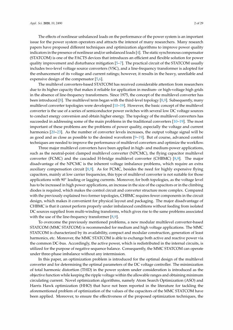
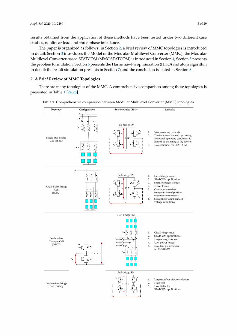
As example, reference [26] presented a comparison between the output voltage and the harmonicspectra generated from the single-phase AC cascaded configuration with two H-bridges on the AC side,which are presented in Figures 1 and 2, and the output voltage and the harmonic spectra generatedfrom the single-phase AC cascaded configuration with 4H-bridges on the AC side, which are presentedin Figures 3 and 4. It can be seen from Figure 2 that the third harmonic component has a large valueand also that the value of THD is extremely high. That is because the method of third harmonicsubtraction allows the multilevel converters to work independently of the load power factor andwithout the problems of capacitor voltage balancing [26]. The data presented in Figure 4 prove thesuperiority of the last configuration of 4H-bridges, as the profile of the output voltage harmonic isslightly better, but with an increase in the number of the power electronic devices and the cost of thesystem. Moreover, reference [26] concludes that the increasing of the series sub-modules (SMs) in thecase of using two H-bridges or 4H-bridges will lead to a reduction in the harmonics and over-shoot inthe output voltages of the MMC.Appl. Sci. 2020, 10, x FOR PEER REVIEW 5 of 34
Voltage(V)
Time(s)
Figure 1. Voltage for a single AC side cascaded configuration including two H-bridges [26].
Figure 2. A representation of the harmonic component in the output voltage of the AC side cascaded configuration using two H-bridges [26].
Figure 1. Voltage for a single AC side cascaded configuration including two H-bridges [26].
Appl. Sci. 2020, 10, x FOR PEER REVIEW 5 of 34
Voltage(V)
Time(s)
Figure 1. Voltage for a single AC side cascaded configuration including two H-bridges [26].
Figure 2. A representation of the harmonic component in the output voltage of the AC side cascaded configuration using two H-bridges [26].
Figure 2. A representation of the harmonic component in the output voltage of the AC side cascadedconfiguration using two H-bridges [26].

Appl. Sci. 2020, 10, 2490 5 of 29Appl. Sci. 2020, 10, x FOR PEER REVIEW 6 of 34
Time(s)
Volta
ge(V
)
Time(s)
Figure 3. Voltage for a single AC side cascaded configuration including 4H-bridges [26].
Figure 4. A representation of the harmonic component in the output voltage of the AC side cascaded configuration using 4H-bridges [26].
3. Model of the Modular Multilevel Converter (MMC)
The modular multilevel converter (MMC) has been introduced firstly by Marquardt in 2001, and is presented as the developed configuration including a number of subsystems for achieving the desired voltage level [15,18,24]. This type of converter is designed for use in medium and high transmission voltages. The overall configuration of the modular multilevel converter is illustrated in Figure 5, where each leg of this converter consists of a lower and an upper arm connected to each other by a DC voltage link.
Figure 3. Voltage for a single AC side cascaded configuration including 4H-bridges [26].
Appl. Sci. 2020, 10, x FOR PEER REVIEW 6 of 34
Time(s)
Volta
ge(V
)
Time(s)
Figure 3. Voltage for a single AC side cascaded configuration including 4H-bridges [26].
Figure 4. A representation of the harmonic component in the output voltage of the AC side cascaded configuration using 4H-bridges [26].
3. Model of the Modular Multilevel Converter (MMC)
The modular multilevel converter (MMC) has been introduced firstly by Marquardt in 2001, and is presented as the developed configuration including a number of subsystems for achieving the desired voltage level [15,18,24]. This type of converter is designed for use in medium and high transmission voltages. The overall configuration of the modular multilevel converter is illustrated in Figure 5, where each leg of this converter consists of a lower and an upper arm connected to each other by a DC voltage link.
Figure 4. A representation of the harmonic component in the output voltage of the AC side cascadedconfiguration using 4H-bridges [26].
The introduced discussion leads the authors to present an optimal design of the control systemand the optimal capacitor value of the MMC for the STATCOM application, using the half-bridge SMsto decrease the number of devices and the cost of implementation.
3. Model of the Modular Multilevel Converter (MMC)
The modular multilevel converter (MMC) has been introduced firstly by Marquardt in 2001, and ispresented as the developed configuration including a number of subsystems for achieving the desiredvoltage level [15,18,24]. This type of converter is designed for use in medium and high transmissionvoltages. The overall configuration of the modular multilevel converter is illustrated in Figure 5, where

Appl. Sci. 2020, 10, 2490 6 of 29
each leg of this converter consists of a lower and an upper arm connected to each other by a DCvoltage link.
Appl. Sci. 2020, 10, x FOR PEER REVIEW 7 of 34
1SM
SM2
NSM
ACR ACLaVbVcV
paU
naU
pai
naicirai
Vdc/2
-Vdc/2
P
N
arm
Rar
mL
1SM
SM2
NSM
1SM
SM2
NSM
1SM
SM2
NSM
1SM
SM2
NSM
1SM
SM2
NSM
Figure 5. The circuit configuration of the MMC.
Each arm includes a number of SMs, and in turn, every sub-system includes two switches and two reverse diodes connected to each other via a DC capacitor. The switches S1 and S2 are operated in reverse. Each SM could be configured as a half-bridge, full-bridge, H-bridge or clamp-double circuit [18]. Due to its low cost and high efficiency, the MMC based on the half-bridge SMs shown in Figure 6 has been widely used in industrial applications and high voltage DC projects. It is possible to perform a selectable individual control for each SM in the converter leg. Principally, the converter legs provided a controllable Voltage Source Converter (VSC) for each phase. The desired waveform voltage can easily be achieved at the terminal by adjusting the terminal voltage of the SM’s leg.
Figure 5. The circuit configuration of the MMC.
Each arm includes a number of SMs, and in turn, every sub-system includes two switches andtwo reverse diodes connected to each other via a DC capacitor. The switches S1 and S2 are operatedin reverse. Each SM could be configured as a half-bridge, full-bridge, H-bridge or clamp-doublecircuit [18]. Due to its low cost and high efficiency, the MMC based on the half-bridge SMs shown inFigure 6 has been widely used in industrial applications and high voltage DC projects. It is possible toperform a selectable individual control for each SM in the converter leg. Principally, the converter legsprovided a controllable Voltage Source Converter (VSC) for each phase. The desired waveform voltagecan easily be achieved at the terminal by adjusting the terminal voltage of the SM’s leg.
The equivalent circuit presentation of the typical MMC using half-bridge SMs is shown in Figure 7,where uvj is the phase converter output voltage and ivj denotes the line current; ipj and inj are the upperand lower leg currents, respectively, that are presented as [8,10,27]:
ipj =ivj2 + idi f f j
inj =ivj2 − idi f f j
(1)

Appl. Sci. 2020, 10, 2490 7 of 29
where idiffj denotes the phase j inter-circulating current that circulates between the upper and lowerlegs and is expressed as below:
idi f f j =ipj − inj
2(2)
Appl. Sci. 2020, 10, x FOR PEER REVIEW 8 of 34
smV
t
ON=1T ON=2T
cV
t
2T,1T= ON
3T,1T=ON
4T,3T=ON
4T,2T=ON
smV
cV
-Vc
1D
4T 4D
C
1T
2D
3T3D
2T
Full Bridge Cell
+
-
cV
smV
1D
2T2D
C
1T
Half Bridge Cell
cV+
-
smV
Figure 6. A schematic of the configuration of the MMC based on half-bridge and full-bridge sub-modules (SMs).
The equivalent circuit presentation of the typical MMC using half-bridge SMs is shown in Figure 7, where uvj is the phase converter output voltage and ivj denotes the line current; ipj and inj are the upper and lower leg currents, respectively, that are presented as [8,10,27]:
2
2
ivji ipj diffj
ivji inj diffj
= +
= −
(1)
where idiffj denotes the phase j inter-circulating current that circulates between the upper and lower legs and is expressed as below:
2
i ipj njidiffj−
=
(2)
Figure 6. A schematic of the configuration of the MMC based on half-bridge and full-bridgesub-modules (SMs).
Appl. Sci. 2020, 10, x FOR PEER REVIEW 9 of 34
unj
pju
-Vdc/2
Vdc/2
+
-uvj
Idc
Idc
pji
inj-
+
+
-
ivj
Rarm
Rarm
Larm
Larm
idiffj
Figure 7. The one phase equivalent circuit.
As discussed in [7], the MMC operates according to the following equations:
( ). . , ,2 2
diR L vjarm armu e i j a b cvj j vj dt= − − =
(3)
( ). . , ,2 2
di u uVdiffj nj pjdcR i L j a b carm armdiffj dt
++ = − =
(4)
where ej denotes the inner emf produced in phase a and is given as follows:
2
u unj pje j−
=
(5)
The internal dynamic performance of the MMC is explained in Equation (4) and can be characterized as follows:
( ). . , ,2 2
di u uVdiffj nj pjdcu R i L j a b carm armdiffj diffj dt
+= + = − =
(6)
where udiffj denotes the phase j inner unbalance voltage. The MMC is characterized by its small size and simplicity in installation, and as the number of
SMs increases, there is a decrease in harmonics and a matching of the required power quality specifications. However, the multilevel converter suffers from converter inter-circulating current, which increases the switches’ conduction loss and increases the thermal stress on the capacitors and switches’ IGBTs. Therefore, maintaining the balance of the capacitor voltages is one of the main rules of the design of the MMC.
4. Modular Multilevel Converter-Based STATCOM (MMC STATCOM)
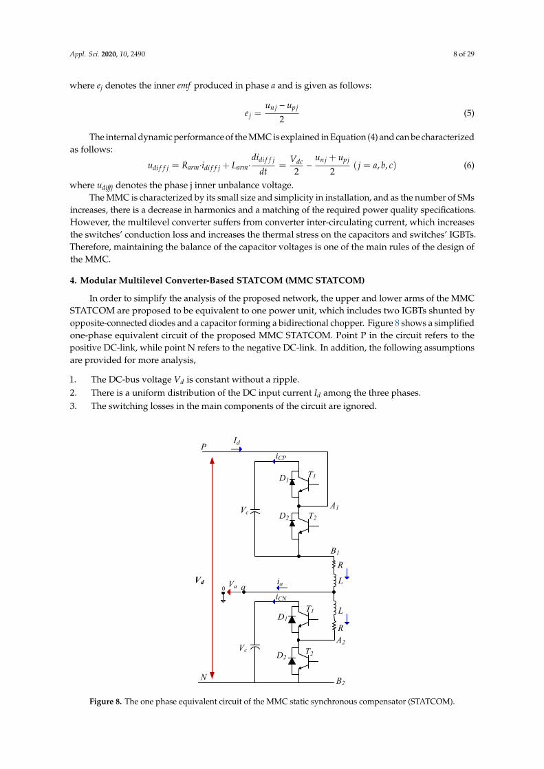
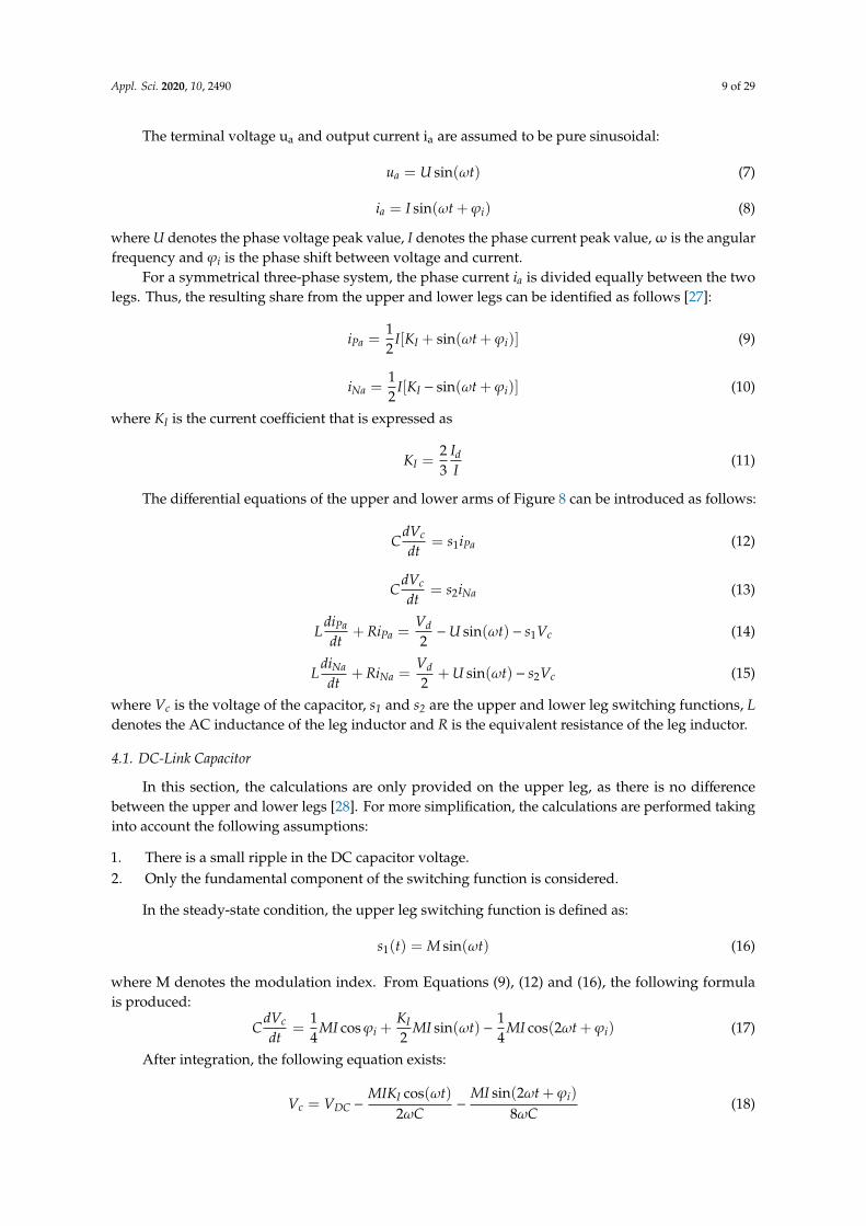
In order to simplify the analysis of the proposed network, the upper and lower arms of the MMC STATCOM are proposed to be equivalent to one power unit, which includes two IGBTs shunted by opposite-connected diodes and a capacitor forming a bidirectional chopper. Figure 8 shows a simplified one-phase equivalent circuit of the proposed MMC STATCOM. Point P in the circuit refers to the positive DC-link, while point N refers to the negative DC-link. In addition, the following assumptions are provided for more analysis,
1. The DC-bus voltage Vd is constant without a ripple. 2. There is a uniform distribution of the DC input current Id among the three phases.
Figure 7. The one phase equivalent circuit.
As discussed in [7], the MMC operates according to the following equations:
uvj = e j −Rarm
2·ivj −
Larm
2·divj
dt( j = a, b, c) (3)
Rarm·idi f f j + Larm·didi f f j
dt=
Vdc2−
unj + upj
2( j = a, b, c) (4)
Appl. Sci. 2020, 10, 2490 8 of 29
where ej denotes the inner emf produced in phase a and is given as follows:
e j =unj − upj
2(5)
The internal dynamic performance of the MMC is explained in Equation (4) and can be characterizedas follows:
udi f f j = Rarm·idi f f j + Larm·didi f f j
dt=
Vdc2−
unj + upj
2( j = a, b, c) (6)
where udiffj denotes the phase j inner unbalance voltage.The MMC is characterized by its small size and simplicity in installation, and as the number of SMs
increases, there is a decrease in harmonics and a matching of the required power quality specifications.However, the multilevel converter suffers from converter inter-circulating current, which increasesthe switches’ conduction loss and increases the thermal stress on the capacitors and switches’ IGBTs.Therefore, maintaining the balance of the capacitor voltages is one of the main rules of the design ofthe MMC.
4. Modular Multilevel Converter-Based STATCOM (MMC STATCOM)
In order to simplify the analysis of the proposed network, the upper and lower arms of the MMCSTATCOM are proposed to be equivalent to one power unit, which includes two IGBTs shunted byopposite-connected diodes and a capacitor forming a bidirectional chopper. Figure 8 shows a simplifiedone-phase equivalent circuit of the proposed MMC STATCOM. Point P in the circuit refers to thepositive DC-link, while point N refers to the negative DC-link. In addition, the following assumptionsare provided for more analysis,
1. The DC-bus voltage Vd is constant without a ripple.2. There is a uniform distribution of the DC input current Id among the three phases.3. The switching losses in the main components of the circuit are ignored.
Appl. Sci. 2020, 10, x FOR PEER REVIEW 10 of 34
3. The switching losses in the main components of the circuit are ignored.
The terminal voltage ua and output current ia are assumed to be pure sinusoidal:
( )sinau U tω=
(7)
( )sina ii I tω ϕ= +
(8)
where U denotes the phase voltage peak value, I denotes the phase current peak value, ω is the angular frequency and φi is the phase shift between voltage and current.
For a symmetrical three-phase system, the phase current ia is divided equally between the two legs. Thus, the resulting share from the upper and lower legs can be identified as follows [27]:
( )1 sin2Pa I ii I K tω ϕ= + +
(9)
R
L
R
L
P
N2B
1T1D
2T2D1A
2A
1T1D
2T2D
cV
cV
1B
a
dI
dV ai
CPi
CNi0 aV
Figure 8. The one phase equivalent circuit of the MMC static synchronous compensator (STATCOM).
( )1 sin2Na I ii I K tω ϕ= − +
(10)
where KI is the current coefficient that is expressed as
23
dI
IKI
=
(11)
The differential equations of the upper and lower arms of Figure 8 can be introduced as follows:
1c
PadVC s idt
=
(12)
Figure 8. The one phase equivalent circuit of the MMC static synchronous compensator (STATCOM).
Appl. Sci. 2020, 10, 2490 9 of 29
The terminal voltage ua and output current ia are assumed to be pure sinusoidal:
ua = U sin(ωt) (7)
ia = I sin(ωt + ϕi) (8)
where U denotes the phase voltage peak value, I denotes the phase current peak value,ω is the angularfrequency and ϕi is the phase shift between voltage and current.
For a symmetrical three-phase system, the phase current ia is divided equally between the twolegs. Thus, the resulting share from the upper and lower legs can be identified as follows [27]:
iPa =12
I[KI + sin(ωt + ϕi)] (9)
iNa =12
I[KI − sin(ωt + ϕi)] (10)
where KI is the current coefficient that is expressed as
KI =23
IdI
(11)
The differential equations of the upper and lower arms of Figure 8 can be introduced as follows:
CdVc
dt= s1iPa (12)
CdVc
dt= s2iNa (13)
LdiPa
dt+ RiPa =
Vd2−U sin(ωt) − s1Vc (14)
LdiNa
dt+ RiNa =
Vd2
+ U sin(ωt) − s2Vc (15)
where Vc is the voltage of the capacitor, s1 and s2 are the upper and lower leg switching functions, Ldenotes the AC inductance of the leg inductor and R is the equivalent resistance of the leg inductor.
4.1. DC-Link Capacitor
In this section, the calculations are only provided on the upper leg, as there is no differencebetween the upper and lower legs [28]. For more simplification, the calculations are performed takinginto account the following assumptions:
1. There is a small ripple in the DC capacitor voltage.2. Only the fundamental component of the switching function is considered.
In the steady-state condition, the upper leg switching function is defined as:
s1(t) = M sin(ωt) (16)
where M denotes the modulation index. From Equations (9), (12) and (16), the following formulais produced:
CdVc
dt=
14
MI cosϕi +KI
2MI sin(ωt) −
14
MI cos(2ωt + ϕi) (17)
After integration, the following equation exists:
Vc = VDC −MIKI cos(ωt)
2ωC−
MI sin(2ωt + ϕi)
8ωC(18)

Appl. Sci. 2020, 10, 2490 10 of 29
where VDC denotes the average DC voltage. The ripple in the current of the upper leg is described bythe following formula:
∆Vc = −MIKI cos(ωt)
2ωC−
MI sin(2ωt + ϕi)
8ωC(19)
By similarity, the ripple in the current of the lower leg is calculated as follows:
∆Vc = −MIKI cos(ωt)
2ωC−
MI sin(2ωt + ϕi)
8ωC(20)
When the phase angle between the voltage and current ϕi equals ±90◦ during the static VArgenerating condition and by ignoring the resistance of the inductor, Equation (19) will be converted to:
∆Vc = −MIKI cos(ωt)
2ωC+
MI sin(2ωt)8ωC
(21)
To obtain the maximum value of the peak-to-peak ripple voltage of the DC capacitor, Equation(21) is differentiated, which results in:
∆Vcpp =MI(KI + 1)2
4ωC(22)
Accordingly, the capacitance of the DC capacitor can be defined as:
C ≥MI(KI + 1)2
4ω∆Vcpp(23)
From Equations (14) and (20) it is clearly shown that the voltage ripple contains the fundamentaland the second harmonic, which dramatically increases the rating of the capacitor, resulting in anincrease in the total cost of the system. An accurate determination of the capacitance value in eachsub-model must be taken into account, as a higher value of the capacitance leads to an increase in thetotal cost of the MMC converter, and on the other hand, a lower value increases the ripple level in theoutput voltage.
4.2. Design of SM Capacitance
The value of the capacitor affects the power quality indices such as the level of the THD and thevoltage balance of the system. Many methods in literature have been introduced to determine thevalues of the capacitors. These methods can be divided into two main methods; the first is based on theidea that the average sum capacitor voltage per arm should be kept constant. The second is based onkeeping constant the individual average capacitor voltages for the sub-modules for each arm. Both ofthe two methods are based on determining the required stored energy of the STATCOM-based MMC.The conclusion based on the literature review is that the first method is considered to be a better choicethan the second one because using the first method improves the reliability of the system, and it ismore convenient for the sub-module capacitor, as well as the semiconductor device, to perform underlow voltage [20]. A general description of the first method has been presented.
Based on the energy storage demands of the converter, the capacitance of the SM can be determined.The minimum value of the capacitance of the SM is calculated as follows [29]:
C =2 ∗N ∗ E
V2dc
(24)
Appl. Sci. 2020, 10, 2490 11 of 29
where E denotes the lowest limit of energy storage for each arm. Due to the similarity between botharms, E for the upper arm can be expressed as reported in [25]:
E =∆E
k2max −max( n2
u−eu,vk2max
1−eu,v)
, (25)
where kmax refers to the capacitor voltage upper boundary. Typically, kmax = 1.1 is commonly used.Finally, as ∆E and E are in direct dependence on the rated power of the converter, the demands
for energy storage of the converter can be given as:
W =6
SnEnom (26)
where W denotes the energy storage needed for each MVA rating. According to [24,30,31], thecapacitance in each sub-module is selected so that the energy stored in all capacitors of the convertersub-modules is about 30–40 kJ/MVA. As the capacitance of the sub-module is not chosen yet, the ripplelevel of the sub-module capacitor voltage in the operating point is simply determined. There aretwo possible ways to obtain an anticipatory value of the voltage ripple. The first way is to assume aripple level of ±10%, whereas the second way is based on assuming a value for the capacitor in eachsub-module in the range, which achieved 30–40kJ/MVA stored energy, then performing simulation inthe time domain to determine the level of the voltage ripple.
4.3. Design of Arm Inductance
Typically, the inductors used in the arms of the MMC are dry-type air-cored ones. The value of theinductance of the arm can be determined based on the way that the short circuits on the DC-side will bedemonstrated. In addition, the inductance of the converter arm plays an important role in enhancingthe characteristics of the inter-circulating current and limiting the fault current. Where bypass thyristorsare used in the sub-modules or where they are separated using additional diode-based power modules,the AC sharing of the fault current on the DC-side does not need to be restricted to provide protectionfor the sub-modules’ anti-parallel diodes. The arm inductance helps in the limitation of the highfrequency harmonics in the inter-circulating current and to provide a smooth control for the circulatingcurrent. A typical value of the arm inductance occurs around 0.05 p.u. [24].
On the other hand, when bypass thyristors are not used in the sub-modules or they are notseparated using additional diode-based power modules, protection for the anti-parallel diodes on theDC-side of the converter have to be designed to protect the sub-modules from the high sharing fromthe AC-side to the fault current in the DC-side. Consequently, as the slow-acting breakers interruptunder this fault current, the arm inductors must restrict the current magnitude to give protection forthe anti-parallel diodes, which act as a conduction path for the fault currents. The value of the arminductance is determined using DC-fault actual time simulation, taking into account the interruptiontime of the circuit breakers, the time delay until fault detection and the strategy of performing the faultin the control system. Typically, the value of the inductance occurred in a range of 0.10–0.15 p.u.
Moreover, a short circuit between the terminals of the DC-buses is performed in order to presentthe most critical fault condition. In order to make a limitation on the short circuit current, the value ofthe arm inductance should be determined according to [29]:
Larm = Vdc/2α (27)
where α (kA/s) denotes the maximum rising rate of the current. Based on (27), when the maximumrising rate is = 0.1(kA/µs) [29], for grid connected converters, the p.u. value of the arm inductancevalues are restricted at 0.3 pu for Double-Star Chopper Cell (DSCC-MMC), as well as for Single-DeltaBridge Cell (SDBC-MMC) configurations.

Appl. Sci. 2020, 10, 2490 12 of 29
Consequently, modern metaheuristic techniques such as Atom Search Optimization (ASO) andHarris hawk’s optimization (HHO) have been proposed in this work for the optimization the of thevalues of capacitors and the coefficients of the DC voltage regulator of the MMC STATCOM, in order tominimize the total harmonic distortion (THD) in the power system under consideration, keeping theripple voltage in the allowable ranges and obtaining minimum current circulation within the converter.
5. Problem Formulation
Usually, in electric power systems, shunt compensating devices are used for voltage and reactivepower control. A MATLAB model for the system under study is shown in Figure 9. The parametersof each component in the system are summarized in Table 2. The system under study compromisesthe utilization of the MMC STATCOM, which is increasingly used in modern electric networks. Theproposed MMC STATCOM is based on full-bridge MMC to form 22 modules per phase power converter.The STATCOM can produce or take reactive power from the grid. The transfer of both types of reactivepower is obtained via phase reactance.
Appl. Sci. 2020, 10, x FOR PEER REVIEW 14 of 34
and phase balancing controllers of the DC-bus voltage, which are responsible for generating the control signals for producing the pulses applied to the gates of the transistors. Moreover, the optimized controller for phase balancing based on the HHO or ASO optimization techniques is shown in Figure 10b, and the optimized controller of DC voltage based on the HHO or ASO optimization techniques is shown in Figure 10c.
Figure 9. A model of the power system under study.
(a)
Figure 9. A model of the power system under study.
Table 2. Parameters of the studied network.
STATCOM power capacity 12 MVA Transformer T1 120 kV/34.5 kVRMS line to line voltage at PCC 34.5 kV Transformer T2 34.5 kV/600 VNumber of MMC in each phase 22 modules Load 1 2 MW
Total stored energy in allsubmodule capacitors
30 kJ/MVA
DC link voltage 1600 Load 2 30 MW & 3 MVArLine frequency 50 Hz Transformer X/R ratio 18
Carrier frequency 300 Hz Load 3 5 MW & 1 MVAr
The proposed MMC generates a three-phase voltage, which has the same phase as that of the gridvoltage at the point of coupling. When the amplitude of the voltage generated from the MMC is lowerthan the grid voltage amplitude, the STATCOM performs like inductance and absorbs reactive powerfrom the grid utility. When the amplitude of the MMC voltage is higher than that of the bus of commoncoupling, the STATCOM works like a capacitor and reactive power will be injected into the grid. The

Appl. Sci. 2020, 10, 2490 13 of 29
control circuit of the MMC is shown in Figure 10a. The controller of the high voltage side includesa phase-locked loop (PLL), transformation and measurement blocks, DC-bus voltage regulator andcurrent regulator. Meanwhile, the controller of the low voltage side includes individual and phasebalancing controllers of the DC-bus voltage, which are responsible for generating the control signalsfor producing the pulses applied to the gates of the transistors. Moreover, the optimized controller forphase balancing based on the HHO or ASO optimization techniques is shown in Figure 10b, and theoptimized controller of DC voltage based on the HHO or ASO optimization techniques is shown inFigure 10c.
Appl. Sci. 2020, 10, x FOR PEER REVIEW 14 of 34
and phase balancing controllers of the DC-bus voltage, which are responsible for generating the control signals for producing the pulses applied to the gates of the transistors. Moreover, the optimized controller for phase balancing based on the HHO or ASO optimization techniques is shown in Figure 10b, and the optimized controller of DC voltage based on the HHO or ASO optimization techniques is shown in Figure 10c.
Figure 9. A model of the power system under study.
(a) Appl. Sci. 2020, 10, x FOR PEER REVIEW 15 of 34
(b)
(c)
Figure 10. The controller of the MMC converter: (a) Simulink configuration; (b) An optimized controller for phase balancing based on the Harris hawk’s optimization (HHO) or Atom search optimization (ASO) optimization techniques; (c) An optimized controller of DC voltage based on the HHO or ASO optimization techniques.
Table 2. Parameters of the studied network.
STATCOM power capacity 12 MVA Transformer T1 120 kV/34.5 kV RMS line to line voltage at PCC 34.5 kV Transformer T2 34.5 kV/600 V Number of MMC in each phase 22
modules Load 1 2 MW
Total stored energy in all submodule capacitors
30 kJ/MVA
DC link voltage 1600 Load 2 30 MW & 3 MVAr
Line frequency 50 Hz Transformer X/R ratio
18
Carrier frequency 300 Hz Load 3 5 MW & 1 MVAr
As discussed in Section 2, the impact of the second component harmonic voltage of the module capacitor on the MMC impedance behavior is expressed. Optimal determination of the value of the module capacitor results in an improvement in the second component of harmonic in the voltage of the module capacitor. Moreover, by reducing the capacitance value, in increase in the second component of harmonic voltage will be observed. Furthermore, it is easy to find that with an increase in the magnitude of the module capacitor voltage second harmonics, an effective increase is observed
Figure 10. The controller of the MMC converter: (a) Simulink configuration; (b) An optimized controllerfor phase balancing based on the Harris hawk’s optimization (HHO) or Atom search optimization(ASO) optimization techniques; (c) An optimized controller of DC voltage based on the HHO or ASOoptimization techniques.

Appl. Sci. 2020, 10, 2490 14 of 29
As discussed in Section 2, the impact of the second component harmonic voltage of the modulecapacitor on the MMC impedance behavior is expressed. Optimal determination of the value of themodule capacitor results in an improvement in the second component of harmonic in the voltage of themodule capacitor. Moreover, by reducing the capacitance value, in increase in the second component ofharmonic voltage will be observed. Furthermore, it is easy to find that with an increase in the magnitudeof the module capacitor voltage second harmonics, an effective increase is observed in the magnitudeof the impedance response at low frequencies, but there is no change noticed in positive-sequence.Starting from the introduced explanation, the optimal determination of the module capacitor canbe addressed as the design of the impedance of the MMC. However, if a stable performance of theSTATCOM is desired, the proposed design should give the minimum demands for energy storageand filtering ripples arising in the capacitance voltage, which shape the constraints of controllingmodule capacitance to produce an optimal impedance response. Therefore, this paper proposes thatthe value of the capacitor should be selected to be optimized to reduce the THD using the HHO andASO algorithm. The objective function to achieve optimal capacitor values leading to the minimumquadratic error of the THD can be calculated as follows:
F1 =
∞∫0
t·THD2dt (28)
Moreover, to achieve the optimal values of both Kp and Ki for each PI controller, which lead to aminimum quadratic error, the objective function can be calculated as follows:
F2 =
∞∫0
t·e2dt (29)
where e. is the error signal between the desired and the typical signals and is fed to the PI controller.The objective function to minimize F can be determined as follows:
Minimize {F(C,(Kp,Ki)VDC,(Kp,Ki)phase balancing} (30)
where F is the summation of the F1 and F2.
6. Proposed Optimization Methods
In the past decades, with the increasing development in the fields of society, economy andindustry, numerous complicated and hardly-solved optimization problems have arisen in all fields.Recently, metaheuristic techniques of optimization have been widely implemented to solve complicatedengineering problems, as they possess high capabilities of exploration and exploitation to reach globalsolutions in a short time when compared with traditional optimization methods [31–34].
Taking into account the No Free Lunch Theorem of Optimization [35], the best solution of differentoptimization problems cannot be fulfilled based on one optimization technique. Based on this theorem,the field of creating and developing better optimization algorithms is still active and full of greatachievements. As a result of these achievements, a recent swarm algorithm inspired by physics, calledAtom Search Optimization (ASO), is proposed for tackling the optimization problem provided in thisstudy. ASO presented superior performance over conventional and recent optimization techniqueswhen validated on numerous mathematical problems. In addition, the proposed ASO algorithmprovided a successful performance when utilized in the optimization problem of hydrogeologicparameter estimation.
In a related context, like the most of existing optimization methods, the searching process in theproposed ASO algorithm is performed in two phases; exploration and exploitation stages [30]. Inthe first phase, the optimization algorithm should make utilization and promotion of the randomly

Appl. Sci. 2020, 10, 2490 15 of 29
initialized operators for the deep exploration of the optimal solution within the search space. Thus, theexploratory behavior of a well-developed optimization algorithm should be randomly enriched togenerate more random solutions to different areas of the addressed problem formed in the early stagesof the research process [36].
6.1. Harris Hawk’s Optimization (HHO)
The HHO algorithm was developed in 2019, which in its operation mimics the behavior of thehunting of the Harris hawks, a group of intelligent birds that live in the USA [32,33]. The huntingmanner of these intelligent birds depends on surprise. A group of hawks appear to their prey (rabbits)from different sides at the same time to surprise it, at which point the best-fit hawk of the group(the leader) surrounds it. Mathematically, the technique of catching the prey of the hawks can bedivided into three stages: (i) the exploration stage, (ii) the stage of transition from exploration toexploitation and finally (iii) the exploitation stage. The first phase of the attack is the most importantas it determines the way that the hawks will act. Firstly, all hawks sit randomly in a high place to givethem a good chance of observing the environment and wait for their chase. When the prey appears inthe surrounding area, the hawks may attack it in several possible manners, and only the leader willdecide the way of attack. All hawks might cooperate and surround the prey, or the leader will give theopportunity to one of them, and it will depend on the behavior of the prey to escape. For each of thetwo possible tactics, the hawks may take their places depending on the location of the neighboringhawk as expressed in (31) or be distributed randomly as described in (32):
X(t + 1) =(Xbest(t) −Xavg(t)
)−ψ(LB + τ(UB− LB)) α < 0.5 (31)
X(t + 1) = Xrand(t) − β∣∣∣Xrand(t) − 2ϕX(t)
∣∣∣ α ≥ 0.5 (32)
where X(t) is the position of the hawks at the present iteration t; X(t+1) is a vector of the new positionsof the hawks in the next iteration; Xbest(t) is the position of the chase (rabbits); and α, β, ψ, ϕ and τare randomly distributed numbers in the range from 0 to 1. UB and LB denote the upper and lowerlimits of the position variables. Xrand(t) denotes a hawk, which is randomly selected from the presentpopulation, and Xavg(t) denotes the mean position of the hawks. The average position of the hawks isdetermined as follows:
Xavg(t) =1N
N∑i=1
Xi(t) (33)
where Xi(t) denotes the position of each hawk in iteration t and N indicates the number of hawks.Depending on the energy of the prey during the escaping process, HHO can make a transition fromexploration to exploitation. The energy of the prey (rabbit) is determined as follows:
E = 2× E0
(1−
tT
)(34)
where, E0 denotes the initial energy in each iteration, which is randomly taken from [−1, 1], and Tpresents the maximum iterations.
As the hawks have detected the prey as explained in the previous stages, they have to makea sudden attack, which depends on the probability of escape. In the mathematical modelling, theprobability of escape r will be <0.5 for a successful escape and r ≥ 0.5 if the prey unsuccessfully getsaway. Depending on the way that the prey will take during escape, the hawks will carry out a softor hard siege. Regardless of the energy of escape, a hard or soft siege will occur. When |E| ≥ 0.5 andr ≥ 0.5, the prey has enough energy to make random jumps but fails to escape. During these miserable

Appl. Sci. 2020, 10, 2490 16 of 29
attempts, the hawks surround the prey until it is exhausted by its force and then suddenly attack it.Thus, the soft siege is described as:
X(t + 1) = ∆X(t) − E∣∣∣(J ×Xbest(t)) −X(t)
∣∣∣ (35)
where ∆X(t) denotes the difference between the prey’s position and the position of the hawks in thepresent iteration. J is the strength of the prey’s random escape.
When |E| < 0.5 and r ≥ 0.5, as the prey has no energy to escape, a hard siege will be performed.Accordingly, the hawks hardly circle the prey to execute a surprise attack. Therefore,
X(t + 1) = Xbest(t) − E∣∣∣∆X(t)
∣∣∣ (36)
Different stages of the HHO algorithm are represented in Figure 11. Moreover, detailedexplanations and mathematical formulations of soft and hard siege manners are provided in [32,33].
Appl. Sci. 2020, 10, x FOR PEER REVIEW 18 of 34
Different stages of the HHO algorithm are represented in Figure 11. Moreover, detailed explanations and mathematical formulations of soft and hard siege manners are provided in [32.33].
Figure 11. The stages of the HHO algorithm [33].
6.2. Atom Search Optimization (ASO)
Atom search optimization is a novel physics-based method for global optimization problems [34,35]. ASO is a population-based technique, which imitates the motion of atoms subjected to interactions and other constraint forces [33,34]. The total forces of interaction that affect the ith atom in the dth dimension are described as follows:
( ) ( )d dF t rand F ti j ijj Kbest=
∈ (37)
where randj is a number randomly distributed in the range [0, 1] and Kbest is a group of K atoms having the best values fitness function. The value of K has to be decreased gradually as the iterations advance, to let ASO perform more exploitation in the latest iterations, as shown in the following expression:
( ) ( )2 tK t N NT
= − − ×
(38)
where N denotes the total number of atoms forming an atomic structure, t denotes the present iteration, and T is the total number of iterations. The interaction force dFi j
presents the gradient of the
potential Lennard-Jones (L-J) and is described in the following formula [29]:
( ) ( )( ) ( )( )13 72 rijdF t h t h tij ij ij rij
η− −
= − −
(39)
where η(t) presents the depth function, which controls the regions of attraction and repulsion; hij(t) is the ratio between the distance between two atoms rij and the scaled distance between them σ(t).
( ) ( )rijh tij tσ
=
(40)
Figure 11. The stages of the HHO algorithm [33].
6.2. Atom Search Optimization (ASO)
Atom search optimization is a novel physics-based method for global optimization problems [34,35].ASO is a population-based technique, which imitates the motion of atoms subjected to interactionsand other constraint forces [33,34]. The total forces of interaction that affect the ith atom in the dthdimension are described as follows:
Fdi (t) =
∑j∈Kbest
rand jFdij(t) (37)
where randj is a number randomly distributed in the range [0, 1] and Kbest is a group of K atoms havingthe best values fitness function. The value of K has to be decreased gradually as the iterations advance,to let ASO perform more exploitation in the latest iterations, as shown in the following expression:
K(t) = N − (N − 2) ×
√tT
(38)

Appl. Sci. 2020, 10, 2490 17 of 29
where N denotes the total number of atoms forming an atomic structure, t denotes the present iteration,and T is the total number of iterations. The interaction force Fd
ij presents the gradient of the potentialLennard-Jones (L-J) and is described in the following formula [29]:
Fdij = −η(t)
[2(hi j(t)
)−13−
(hi j(t)
)−7]→r i j
ri j(39)
where η(t) presents the depth function, which controls the regions of attraction and repulsion; hij(t) isthe ratio between the distance between two atoms rij and the scaled distance between them σ(t).
hi j(t) =ri j
σ(t)(40)
η(t) = α(1−
t− 1T
)3e−
20tT (41)
where α denotes the depth weight. The function of the force of interaction under different values of ηwith respect to a variable scaled distance (h changed from 0.9 to 1) is presented in Figure 12.
Appl. Sci. 2020, 10, x FOR PEER REVIEW 19 of 34
( )20311tTtt e
Tη α
−− = −
(41)
where α denotes the depth weight. The function of the force of interaction under different values of η with respect to a variable scaled distance (h changed from 0.9 to 1) is presented in Figure 12.
Figure 12. The behavior of the interaction force function with the scaled distance (h) under different depth values [34].
Equation (42) presents the expression of the scaled distance between any two atoms i and j:
( )
( )( )
( )( )
( )( )
( )( )
min min
maxmin
max max
r tijh ht
r t r tij ijh t h hij t t
r tijh ht
σ
σ σ
σ
<
= ≤ ≤ >
(42)
where hmin and hmax describe the upper and lower limits of the distance (h), respectively, and are determined by the following formula:
( )0minmax
h g g t
h u
= +
=
(43)
( ) 0.1 sin2
tg tT
π = × ×
(44)
( ) ( )( )
( )2
,x tijj Kbestt x tij K t
σ
∈=
(45)
where g0 and u denote the lower and upper limits, respectively. g(t) denotes a drift factor to give the algorithm the ability to transform from the exploration to the exploitation stage.
Figure 12. The behavior of the interaction force function with the scaled distance (h) under differentdepth values [34].
Equation (42) presents the expression of the scaled distance between any two atoms i and j:
hi j(t) =
hmin
ri j(t)σ(t) < hmin
ri j(t)σ(t) hmin ≤
ri j(t)σ(t) ≤ hmax
hmaxri j(t)σ(t) > hmax
(42)
where hmin and hmax describe the upper and lower limits of the distance (h), respectively, and aredetermined by the following formula: {
hmin = g0 + g(t)hmax = u
(43)
g(t) = 0.1× sin(π2×
tT
)(44)
Appl. Sci. 2020, 10, 2490 18 of 29
σ(t) = ‖xi j(t),
∑j∈Kbest
xi j(t)
K(t)‖
2(45)
where g0 and u denote the lower and upper limits, respectively. g(t) denotes a drift factor to give thealgorithm the ability to transform from the exploration to the exploitation stage.
Presuming that there is a covalent bond between each atom in ASO and the best one, the constraintforce resulting from this combination be expressed as follows:
Gdi (t) = λ(t)
(xd
best(t) − xdi (t)
)(46)
whereλ(t) = β× e−
20tT (47)
where xdbest(t) denotes the location of the best atom in the dth dimension, λ(t) indicates the Lagrangian
multiplier, and β denotes a multiplier weight. After defining the forces of interaction and L-J potentialresultant constraint force, the acceleration, to which the ith atom is projected in the dimension d anditeration t, is determined as follows:
adi (t) =
Fdi (t)
mdi (t)
+Gd
i (t)
mdi (t)
= α(1− t−1
T
)3e−
20tT
×∑
j∈Kbest
rand j
[2(hi j(t))
−13−(hi j(t))
−7]
mi(t)
·
(xd
j (t)−xdi (t)
)‖→x i(t),
→x j(t)‖2
+ βe−20tT(xd
best(t)−xdi (t))
mi(t)
(48)
where mdi (t) denotes the mass of the atom number i in the dimension d of iteration t, and is determined
from the value of its fitness function as described below:
Mi(t) = e−
Fiti(t)−Fitbest(t)Fitworst(t)−Fitbest(t) (49)
mi(t) =Mi(t)∑N
j=1 M j(t)(50)
whereFitbest(t) = min
i∈{1,2,...,N}Fiti(t) (51)
Fitworst(t) = maxi∈{1,2,...,N}
Fiti(t) (52)
Finally, the velocity of the ith atom in the search space and the new position acquired at the nextiteration (t+1) can be described by the following formulas:
vdi (t + 1) = randd
i ·vdi (t) + ad
i (t) (53)
xdi (t + 1) = xd
i (t) + vdi (t + 1) (54)
For a deeper explanation of the atom search optimization technique, the procedure is discussed indetail in [34,35].
7. Results and Discussion
The simulation results have been obtained to validate the effectiveness of the proposed optimizationtechniques in determining the optimal values of the capacitance and the parameters of the DC voltageregulator. Moreover, to validate the accuracy of the those obtained from the results, these values have
Appl. Sci. 2020, 10, 2490 19 of 29
been applied to the system under study under the integration of nonlinear loads and the conditionof three-phase imbalance. The performance of the MMC STATCOM in the two study cases has beenintroduced in the simulation results.
7.1. Nonlinear Load Case Study
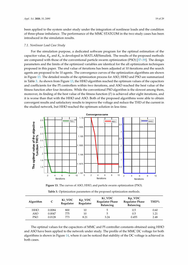
For the simulation purpose, a dedicated software program for the optimal estimation of thecapacitor value, Kp and Ki, is developed in MATLAB/Simulink. The results of the proposed methodsare compared with those of the conventional particle swarm optimization (PSO) [37–39]. The designparameters and the limits of the optimized variables are identical for the all optimization techniquesproposed in this paper. The end value of iterations has been adjusted at 10 iterations and the searchagents are proposed to be 10 agents. The convergence curves of the optimization algorithms are shownin Figure 13. The detailed results of the optimization process for ASO, HHO and PSO are summarizedin Table 3. As shown from Figure 13, the HHO algorithm reached the optimum values of the capacitorsand coefficients for the PI controllers within two iterations, and ASO reached the best value of thefitness function after four iterations. While the conventional PSO algorithm is the slowest among them,moreover, its finding of the best value of the fitness function (F) is achieved after eight iterations, andit is worse than that with the HHO and ASO. Both of the proposed algorithms were able to obtainconvergent results and satisfactory results to improve the voltage and reduce the THD of the current inthe studied network, but HHO reached the optimum solution in less time.
Appl. Sci. 2020, 10, x FOR PEER REVIEW 21 of 34
For a deeper explanation of the atom search optimization technique, the procedure is discussed in detail in [34,35].
7. Results and Discussion
The simulation results have been obtained to validate the effectiveness of the proposed optimization techniques in determining the optimal values of the capacitance and the parameters of the DC voltage regulator. Moreover, to validate the accuracy of the those obtained from the results, these values have been applied to the system under study under the integration of nonlinear loads and the condition of three-phase imbalance. The performance of the MMC STATCOM in the two study cases has been introduced in the simulation results.
7.1. Nonlinear Load Case Study
For the simulation purpose, a dedicated software program for the optimal estimation of the capacitor value, Kp and Ki, is developed in MATLAB/Simulink. The results of the proposed methods are compared with those of the conventional particle swarm optimization (PSO) [37–39]. The design parameters and the limits of the optimized variables are identical for the all optimization techniques proposed in this paper. The end value of iterations has been adjusted at 10 iterations and the search agents are proposed to be 10 agents. The convergence curves of the optimization algorithms are shown in Figure 13. The detailed results of the optimization process for ASO, HHO and PSO are summarized in Table 3. As shown from Figure 13, the HHO algorithm reached the optimum values of the capacitors and coefficients for the PI controllers within two iterations, and ASO reached the best value of the fitness function after four iterations. While the conventional PSO algorithm is the slowest among them, moreover, its finding of the best value of the fitness function (F) is achieved after eight iterations, and it is worse than that with the HHO and ASO. Both of the proposed algorithms were able to obtain convergent results and satisfactory results to improve the voltage and reduce the THD of the current in the studied network, but HHO reached the optimum solution in less time.
2 4 6 8 10Iterations
0.5
1
1.5
2
2.5
3
3.5HHO
0 2 4 6 8 10Iterations
1.187
1.1875
1.188
1.1885
1.189
1.1895
1.19ASO
2 4 6 8 10Iterations
1.8
1.9
2
2.1
2.2
2.3
2.4
2.5
Convergence curve
PSO
Figure 13. The curves of ASO, HHO, and particle swarm optimization (PSO).
Figure 13. The curves of ASO, HHO, and particle swarm optimization (PSO).
Table 3. Optimization parameters of the proposed optimization methods.
Algorithm C Ki_VDCRegulator
Kp_VDCRegulator
Ki_VDCRegulator Phase
Balancing
Kp_VDCRegulator Phase
BalancingTHD%
HHO 0.0084 800 10 5 0.5 0.60ASO 0.0047 775 10 5 0.5 1.21PSO 0.0128 773 8.21 3.24 0.455 2.48
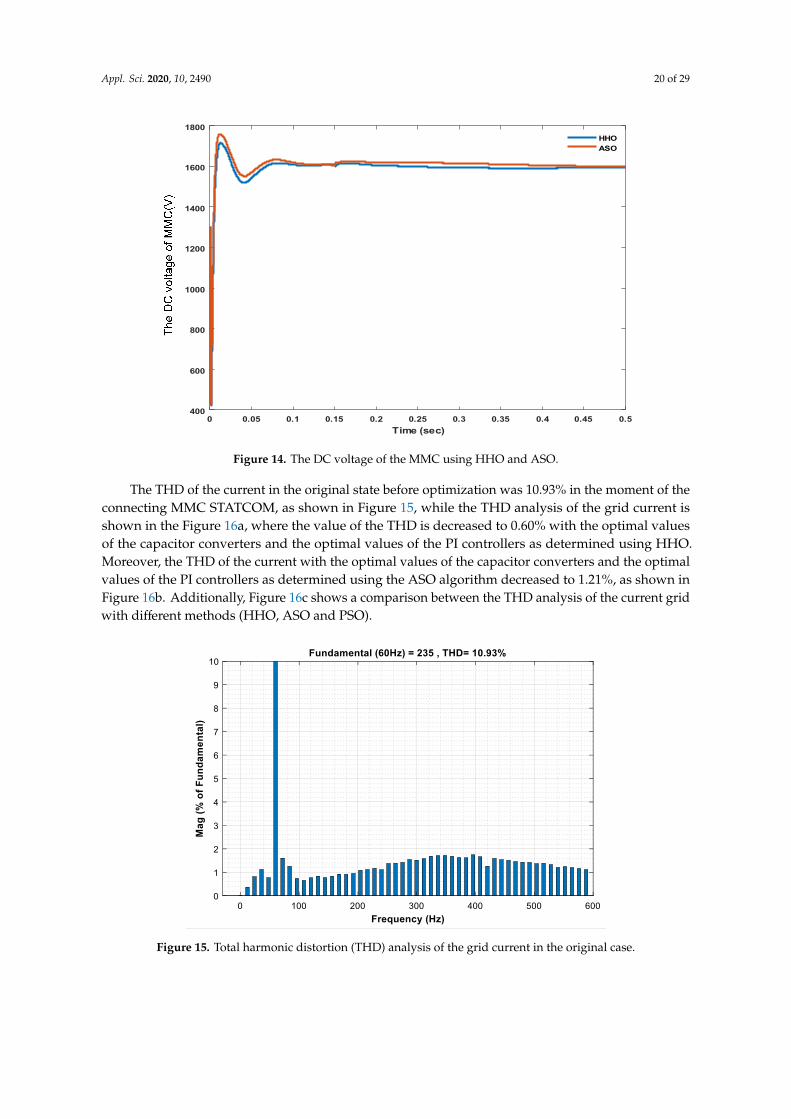
The optimal values for the capacitors of MMC and PI controller constants obtained using HHOand ASO have been applied to the network under study. The profile of the MMC DC voltage for bothalgorithms is shown in Figure 14, where it can be noticed that stability of the DC voltage is achieved inboth cases.
Appl. Sci. 2020, 10, 2490 20 of 29
Appl. Sci. 2020, 10, x FOR PEER REVIEW 22 of 34
Table 3. Optimization parameters of the proposed optimization methods.
Algorithm C Ki_VDC Regulator
Kp_VDC Regulator
Ki_VDC Regulator Phase Balancing
Kp_VDC Regulator Phase Balancing
THD%
HHO 0.0084 800 10 5 0.5 0.60 ASO 0.0047 775 10 5 0.5 1.21 PSO 0.0128 773 8.21 3.24 0.455 2.48
The optimal values for the capacitors of MMC and PI controller constants obtained using HHO and ASO have been applied to the network under study. The profile of the MMC DC voltage for both algorithms is shown in Figure 14, where it can be noticed that stability of the DC voltage is achieved in both cases.
The THD of the current in the original state before optimization was 10.93% in the moment of the connecting MMC STATCOM, as shown in Figure 15, while the THD analysis of the grid current is shown in the Figure 16a, where the value of the THD is decreased to 0.60% with the optimal values of the capacitor converters and the optimal values of the PI controllers as determined using HHO. Moreover, the THD of the current with the optimal values of the capacitor converters and the optimal values of the PI controllers as determined using the ASO algorithm decreased to 1.21%, as shown in Figure 16b. Additionally, Figure 16c shows a comparison between the THD analysis of the current grid with different methods (HHO, ASO and PSO).
0 0.05 0.1 0.15 0.2 0.25 0.3 0.35 0.4 0.45 0.5Time (sec)
400
600
800
1000
1200
1400
1600
1800HHOASO
Figure 14. The DC voltage of the MMC using HHO and ASO.
Figure 14. The DC voltage of the MMC using HHO and ASO.
The THD of the current in the original state before optimization was 10.93% in the moment of theconnecting MMC STATCOM, as shown in Figure 15, while the THD analysis of the grid current isshown in the Figure 16a, where the value of the THD is decreased to 0.60% with the optimal valuesof the capacitor converters and the optimal values of the PI controllers as determined using HHO.Moreover, the THD of the current with the optimal values of the capacitor converters and the optimalvalues of the PI controllers as determined using the ASO algorithm decreased to 1.21%, as shown inFigure 16b. Additionally, Figure 16c shows a comparison between the THD analysis of the current gridwith different methods (HHO, ASO and PSO).Appl. Sci. 2020, 10, x FOR PEER REVIEW 23 of 34
Figure 15. Total harmonic distortion (THD) analysis of the grid current in the original case.
(a)
(b)
Figure 15. Total harmonic distortion (THD) analysis of the grid current in the original case.

Appl. Sci. 2020, 10, 2490 21 of 29
Appl. Sci. 2020, 10, x FOR PEER REVIEW 23 of 34
Figure 15. Total harmonic distortion (THD) analysis of the grid current in the original case.
(a)
(b) Appl. Sci. 2020, 10, x FOR PEER REVIEW 24 of 34
(c)
Figure 16. (a) The THD analysis of the current grid using HHO; (b) The THD analysis of the current
grid using ASO; (c) Comparison between the THD analysis of the current grid with different methods.
0.61.21
2.48
10.93
0
2
4
6
8
10
12
HOO ASO PSO Original
Case
TH
D %
Figure 16. (a) The THD analysis of the current grid using HHO; (b) The THD analysis of the currentgrid using ASO; (c) Comparison between the THD analysis of the current grid with different methods.

Appl. Sci. 2020, 10, 2490 22 of 29
The improvement of the voltage profile by compensating the reactive power is one of the mainprospective results of MMC STATCOM. In order to examine the operation of the MMC STATCOM withthe reactive power command, Qref is changed from (−5 MVAr); in this case the STATCOM operates inthe inductive mode, to (+10 MVAr), where the STATCOM operates in the capacitive mode.
The grid side voltage and current of the MMC STATCOM are shown in Figure 17. As shown fromFigure 17, when the set-point of the reference reactive power changed at 0.15 s, the current drawn fromthe grid steps from lagging the grid voltage by 90 degrees to leading the voltage by 90 degrees. Thecontrol system of the STATCOM introduces a rapid reaction for modifying the terminal voltage ofthe inverter in order to produce 10 MVAr of reactive power (capacitive mode). The load current andoutput voltage are represented in Figure 18.
Appl. Sci. 2020, 10, x FOR PEER REVIEW 25 of 34
The improvement of the voltage profile by compensating the reactive power is one of the main prospective results of MMC STATCOM. In order to examine the operation of the MMC STATCOM with the reactive power command, Qref is changed from (−5 MVAr); in this case the STATCOM operates in the inductive mode, to (+10 MVAr), where the STATCOM operates in the capacitive mode.
The grid side voltage and current of the MMC STATCOM are shown in Figure 17. As shown from Figure 17, when the set-point of the reference reactive power changed at 0.15 s, the current drawn from the grid steps from lagging the grid voltage by 90 degrees to leading the voltage by 90 degrees. The control system of the STATCOM introduces a rapid reaction for modifying the terminal voltage of the inverter in order to produce 10 MVAr of reactive power (capacitive mode). The load current and output voltage are represented in Figure 18.
The active and reactive power with the connection of the MMC STATCOM is presented in Figure 19a,b respectively. From the figure, a high dynamic performance with acceptable raise time has been achieved for the reactive power variation. Moreover, the three-phase voltage of the converters in this case of study is shown in Figure 20.
0.1 0.12 0.14 0.16 0.18 0.2 0.22Time(sec)
-3
-2
-1
0
1
2
3
4
Volta
ge
104
Appl. Sci. 2020, 10, x FOR PEER REVIEW 26 of 34
0.1 0.12 0.14 0.16 0.18 0.2Time(sec)
-800
-600
-400
-200
0
200
400
600
800
Curr
ent
Cur
rent
(A)
Figure 17. The grid side voltage and current.
0.1 0.12 0.14 0.16 0.18 0.2 0.22Time(sec)
-500
-400
-300
-200
-100
0
100
200
300
400
500
Volta
geVo
ltage
(V)
Time(s)
Figure 17. The grid side voltage and current.

Appl. Sci. 2020, 10, 2490 23 of 29
Appl. Sci. 2020, 10, x FOR PEER REVIEW 26 of 34
0.1 0.12 0.14 0.16 0.18 0.2Time(sec)
-800
-600
-400
-200
0
200
400
600
800
Curr
ent
Cur
rent
(A)
Figure 17. The grid side voltage and current.
0.1 0.12 0.14 0.16 0.18 0.2 0.22Time(sec)
-500
-400
-300
-200
-100
0
100
200
300
400
500
Volta
geVo
ltage
(V)
Time(s)Appl. Sci. 2020, 10, x FOR PEER REVIEW 27 of 34
0.1 0.12 0.14 0.16 0.18 0.2 0.22Time(sec)
-8000
-6000
-4000
-2000
0
2000
4000
6000
8000
Curre
nt
Figure 18. The load side voltage and current.
0 0.05 0.1 0.15 0.2 0.25 0.3Time(sec)
-1.5
-1
-0.5
0
0.5
1
1.5
Rea
ctiv
e po
wer
107
(MV
Ar)
Time(s)
(Var
)
(a)
Figure 18. The load side voltage and current.
The active and reactive power with the connection of the MMC STATCOM is presented inFigure 19a,b respectively. From the figure, a high dynamic performance with acceptable raise time hasbeen achieved for the reactive power variation. Moreover, the three-phase voltage of the converters inthis case of study is shown in Figure 20.
Appl. Sci. 2020, 10, x FOR PEER REVIEW 27 of 34
0.1 0.12 0.14 0.16 0.18 0.2 0.22Time(sec)
-8000
-6000
-4000
-2000
0
2000
4000
6000
8000
Curre
nt
Figure 18. The load side voltage and current.
0 0.05 0.1 0.15 0.2 0.25 0.3Time(sec)
-1.5
-1
-0.5
0
0.5
1
1.5
Rea
ctiv
e po
wer
107
(MV
Ar)
Time(s)
(Var
)
(a)
Figure 19. Cont.

Appl. Sci. 2020, 10, 2490 24 of 29Appl. Sci. 2020, 10, x FOR PEER REVIEW 28 of 34
(W)
Time(s)
(b)
Figure 19. The reactive and active power with connection to the MMC STATCOM. (a) Reactive
power; (b) Active power.
0.1 0.12 0.14 0.16 0.18 0.2 0.22
Time(sec)
-4
-3
-2
-1
0
1
2
3
4104
Vo
lta
ge
(V)
Time(s)
Figure 20. Phase voltage converters.
Figure 19. The reactive and active power with connection to the MMC STATCOM. (a) Reactive power;(b) Active power.
Appl. Sci. 2020, 10, x FOR PEER REVIEW 28 of 34
(b)
Figure 19. The reactive and active power with connection to the MMC STATCOM. (a) Reactive power; (b) Active power.
0.1 0.12 0.14 0.16 0.18 0.2 0.22Time(sec)
-4
-3
-2
-1
0
1
2
3
4 104
Figure 20. Phase voltage converters.
Figure 20. Phase voltage converters.
7.2. Unbalanced Load Case Study
For more validation of the proposed configuration, the system has been tested under the case ofunbalanced load. In this case of study, the load on phase C has been assumed to be changed at 1 s by3 s, and the current at the grid side with imbalanced load is shown in Figure 21. The effectiveness of theproposed control scheme based on the optimization technique of HHO is examined. The voltages andcurrents at the load side are shown in Figure 22. Figure 23 shows the grid side voltages and currents,which indicate a balance in the grid currents and voltages. Moreover, Figure 24 shows the DC linkvoltage of the MMC for this case of study. As observed from the figures, in the case of imbalanced load,the proposed MMC STATCOM with the optimal design based on the optimization algorithms was ableto maintain the voltage and currents as balanced as possible. Moreover, the maintenance of the voltagein the DC-link, constant without fluctuations, was also desired, and it has been achieved as observedin Figure 24.

Appl. Sci. 2020, 10, 2490 25 of 29
Appl. Sci. 2020, 10, x FOR PEER REVIEW 29 of 34
7.2. Unbalanced Load Case Study
For more validation of the proposed configuration, the system has been tested under the case of unbalanced load. In this case of study, the load on phase C has been assumed to be changed at 1 s by 3 s, and the current at the grid side with imbalanced load is shown in Figure 21. The effectiveness of the proposed control scheme based on the optimization technique of HHO is examined. The voltages and currents at the load side are shown in Figure 22. Figure 23 shows the grid side voltages and currents, which indicate a balance in the grid currents and voltages. Moreover, Figure 24 shows the DC link voltage of the MMC for this case of study. As observed from the figures, in the case of imbalanced load, the proposed MMC STATCOM with the optimal design based on the optimization algorithms was able to maintain the voltage and currents as balanced as possible. Moreover, the maintenance of the voltage in the DC-link, constant without fluctuations, was also desired, and it has been achieved as observed in Figure 24.
1.02 1.04 1.06 1.08 1.1 1.12 1.14 1.16 1.18Time(sec)
-50
-40
-30
-20
-10
0
10
20
30
40
50
Figure 21. The current at the grid side with an imbalanced load. Figure 21. The current at the grid side with an imbalanced load.
Appl. Sci. 2020, 10, x FOR PEER REVIEW 30 of 34
0.94 0.96 0.98 1 1.02 1.04 1.06 1.08 1.1Time (sec)
-500
-400
-300
-200
-100
0
100
200
300
400
500
Volta
ge
0.96 0.97 0.98 0.99 1 1.01 1.02 1.03Time(sec)
-8000
-6000
-4000
-2000
0
2000
4000
6000
8000
Curre
ntC
urre
nt(A
)
Time(s)
-
-
Figure 22. The magnitude voltage and current load with an imbalanced load.
0.94 0.95 0.96 0.97 0.98 0.99 1 1.01Time (sec)
-4
-3
-2
-1
0
1
2
3
4
Volta
ge
104
Figure 22. The magnitude voltage and current load with an imbalanced load.
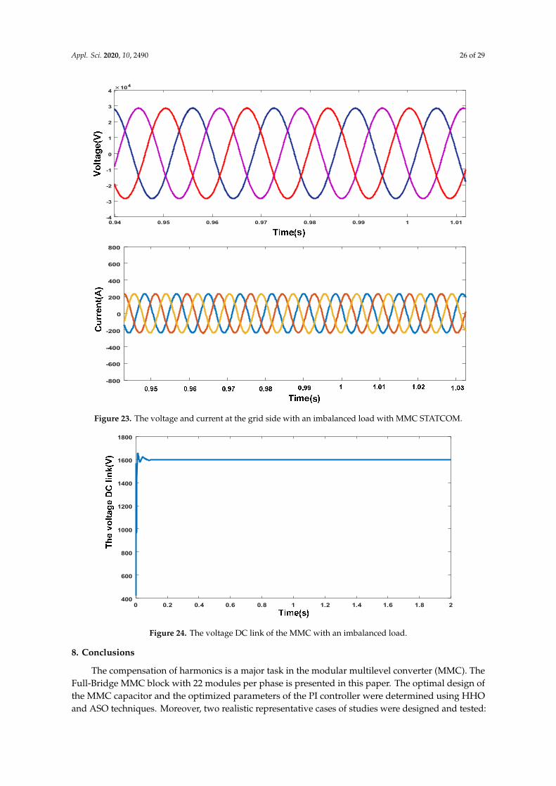
Appl. Sci. 2020, 10, 2490 26 of 29
Appl. Sci. 2020, 10, x FOR PEER REVIEW 30 of 34
0.94 0.96 0.98 1 1.02 1.04 1.06 1.08 1.1Time (sec)
-500
-400
-300
-200
-100
0
100
200
300
400
500
Volta
ge
0.96 0.97 0.98 0.99 1 1.01 1.02 1.03Time(sec)
-8000
-6000
-4000
-2000
0
2000
4000
6000
8000
Curre
ntC
urre
nt(A
)
Time(s)
-
-
Figure 22. The magnitude voltage and current load with an imbalanced load.
0.94 0.95 0.96 0.97 0.98 0.99 1 1.01Time (sec)
-4
-3
-2
-1
0
1
2
3
4
Volta
ge104
Appl. Sci. 2020, 10, x FOR PEER REVIEW 31 of 34
0.98 1 1.02 1.04 1.06 1.08 1.1 1.12 1.14Time (sec)
-800
-600
-400
-200
0
200
400
600
800
Curre
nt
Figure 23. The voltage and current at the grid side with an imbalanced load with MMC STATCOM.
0 0.2 0.4 0.6 0.8 1 1.2 1.4 1.6 1.8 2Time (sec)
400
600
800
1000
1200
1400
1600
1800
Figure 24. The voltage DC link of the MMC with an imbalanced load.
8. Conclusions
The compensation of harmonics is a major task in the modular multilevel converter (MMC). The Full-Bridge MMC block with 22 modules per phase is presented in this paper. The optimal design of the MMC capacitor and the optimized parameters of the PI controller were determined using HHO and ASO techniques. Moreover, two realistic representative cases of studies were designed and tested: nonlinear and imbalanced loads. The THD of the current before applying the proposed algorithm was 10.97%, where with the optimal values of the capacitor converters, the THD decreased to 0.60% by using the HHO algorithm, whereas THD decreased to 1.21% using the ASO. The results show that with the application of the MMC STATCOM, the voltage and current load are rapidly adjusted in the case of the imbalanced load. Moreover, the voltage DC-link of the converter has a stability value, and this will reduce the value of the current circulation within the converter. In the two cases of nonlinear and imbalanced loads, the voltage in the DC-link has a stabilized value, and this, in turn, improves the performance of the control system and the power quality indicators in the studied network. In addition, the application of the MMC in grid-connected photovoltaic and wind energy systems and micro grids is also an important issue for our future works. In spite of this, the study of this topic is outside of the framework of this paper, and it can be covered in future works.
Figure 23. The voltage and current at the grid side with an imbalanced load with MMC STATCOM.
Appl. Sci. 2020, 10, x FOR PEER REVIEW 31 of 34
0.98 1 1.02 1.04 1.06 1.08 1.1 1.12 1.14Time (sec)
-800
-600
-400
-200
0
200
400
600
800
Curre
nt
Figure 23. The voltage and current at the grid side with an imbalanced load with MMC STATCOM.
0 0.2 0.4 0.6 0.8 1 1.2 1.4 1.6 1.8 2Time (sec)
400
600
800
1000
1200
1400
1600
1800
Figure 24. The voltage DC link of the MMC with an imbalanced load.
8. Conclusions
The compensation of harmonics is a major task in the modular multilevel converter (MMC). The Full-Bridge MMC block with 22 modules per phase is presented in this paper. The optimal design of the MMC capacitor and the optimized parameters of the PI controller were determined using HHO and ASO techniques. Moreover, two realistic representative cases of studies were designed and tested: nonlinear and imbalanced loads. The THD of the current before applying the proposed algorithm was 10.97%, where with the optimal values of the capacitor converters, the THD decreased to 0.60% by using the HHO algorithm, whereas THD decreased to 1.21% using the ASO. The results show that with the application of the MMC STATCOM, the voltage and current load are rapidly adjusted in the case of the imbalanced load. Moreover, the voltage DC-link of the converter has a stability value, and this will reduce the value of the current circulation within the converter. In the two cases of nonlinear and imbalanced loads, the voltage in the DC-link has a stabilized value, and this, in turn, improves the performance of the control system and the power quality indicators in the studied network. In addition, the application of the MMC in grid-connected photovoltaic and wind energy systems and micro grids is also an important issue for our future works. In spite of this, the study of this topic is outside of the framework of this paper, and it can be covered in future works.
Figure 24. The voltage DC link of the MMC with an imbalanced load.
8. Conclusions
The compensation of harmonics is a major task in the modular multilevel converter (MMC). TheFull-Bridge MMC block with 22 modules per phase is presented in this paper. The optimal design ofthe MMC capacitor and the optimized parameters of the PI controller were determined using HHOand ASO techniques. Moreover, two realistic representative cases of studies were designed and tested:
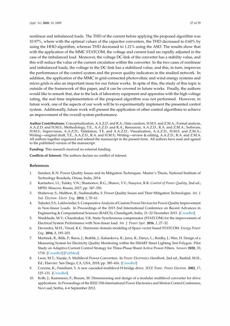
Appl. Sci. 2020, 10, 2490 27 of 29
nonlinear and imbalanced loads. The THD of the current before applying the proposed algorithm was10.97%, where with the optimal values of the capacitor converters, the THD decreased to 0.60% byusing the HHO algorithm, whereas THD decreased to 1.21% using the ASO. The results show thatwith the application of the MMC STATCOM, the voltage and current load are rapidly adjusted in thecase of the imbalanced load. Moreover, the voltage DC-link of the converter has a stability value, andthis will reduce the value of the current circulation within the converter. In the two cases of nonlinearand imbalanced loads, the voltage in the DC-link has a stabilized value, and this, in turn, improvesthe performance of the control system and the power quality indicators in the studied network. Inaddition, the application of the MMC in grid-connected photovoltaic and wind energy systems andmicro grids is also an important issue for our future works. In spite of this, the study of this topic isoutside of the framework of this paper, and it can be covered in future works. Finally, the authorswould like to remark that, due to the lack of laboratory equipment and apparatus with the high voltagerating, the real time implementation of the proposed algorithm was not performed. However, infuture work, one of the aspects of our work will be to experimentally implement the presented controlsystem. Additionally, future work will present the application of other control algorithms to achievean improvement of the overall system performance.
Author Contributions: Conceptualization, A.A.Z.D. and R.A.; Data curation, H.M.S. and Z.M.A.; Formal analysis,A.A.Z.D. and H.M.S.; Methodology, T.E., A.A.Z.D. and R.A.; Resources, A.A.Z.D., R.A. and Z.M.A.; Software,H.M.S.; Supervision, A.A.Z.D.; Validation, T.E. and A.A.Z.D.; Visualization, A.A.Z.D., H.M.S. and Z.M.A.;Writing—original draft, T.E., A.A.Z.D., R.A. and H.M.S.; Writing—review & editing, A.A.Z.D., R.A. and Z.M.A.All authors together organized and refined the manuscript in the present form. All authors have read and agreedto the published version of the manuscript.
Funding: This research received no external funding.
Conflicts of Interest: The authors declare no conflict of interest.
References
1. Sandeer, K.N. Power Quality Issues and its Mitigation Techniques. Master’s Thesis, National Institute ofTechnology Rourkela, Orissa, India, 2014.
2. Kartashov, I.I.; Tulsky, V.N.; Shamonov, R.G.; Sharov, Y.V.; Nasyrov, R.R. Control of Power Quality, 2nd ed.;MPEI: Moscow, Russia, 2017; pp. 347–350.
3. Shahewar, S.; Malthon, R.; Sushmalatha, S. Power Quality Issues and Their Mitigation Technologies. Int. J.Ind. Electron. Electr. Eng. 2014, 2, 55–61.
4. Tejinder, S.S.; Lakhwinder, S. Comparative Analysis of Custom Power Devices for Power Quality Improvementin Non-linear Loads. In Proceedings of the 2015 2nd International Conference on Recent Advances inEngineering & Computational Sciences (RAECS), Chandigarh, India, 21–22 December 2015. [CrossRef]
5. Wankhede, M.V.; Chandrakar, V.K. Static Synchronous compensator (STATCOM) for the improvement ofElectrical System Performance with Non-linear load. Int. J. Power Syst. 2016, 1, 27–32.
6. Devendra, M.H.; Vinod, K.C. Harmonic domain modeling of Space vector based STATCOM. Energy PowerEng. 2016, 8, 195–203.
7. Martinek, R.; Bilik, P.; Baros, J.; Brablik, J.; Kahankova, R.; Jaros, R.; Danys, L.; Rzidky, J.; Wen, H. Design of aMeasuring System for Electricity Quality Monitoring within the SMART Street Lighting Test Polygon: PilotStudy on Adaptive Current Control Strategy for Three-Phase Shunt Active Power Filters. Sensors 2020, 20,1718. [CrossRef] [PubMed]
8. Leon, M.T.; Xiaojie, S. Multilevel Power Converters. In Power Electronics Handbook, 2nd ed.; Rashid, M.H.,Ed.; Elsevier: San Diego, CA, USA, 2018; pp. 385–416. [CrossRef]
9. Corzine, K.; Familiant, Y. A new cascaded multilevel H-bridge drive. IEEE Trans. Power Electron. 2002, 17,125–131. [CrossRef]
10. Kolb, J.; Kammerer, F.; Braum, M. Dimensioning and design of a modular multilevel converter for driveapplications. In Proceedings of the IEEE 15th International Power Electronics and Motion Control Conference,Novi sad, Serbia, 4–6 September 2012.
Appl. Sci. 2020, 10, 2490 28 of 29
11. Dekka, A.; Bin, W.; Zargari, N.R.; Fuentes, R.L. A space-vector PWM-based voltage-balancing approach withreduced current sensors for modular multilevel converter. IEEE Trans. Ind. Electron. 2016, 63, 2734–2745.[CrossRef]
12. Hammond, P.W. Four-quadrant AC-AC Drive and Method. U.S. Patent 6,166,513, 26 December 2000.13. Aiello, M.F.; Hammond, P.W.; Rastogi, M. Modular Multi-Level Adjustable Supply with Series Connected
Active Inputs. U.S. Patent 6,236,580, 22 May 2001.14. Aiello, M.F.; Hammond, P.W.; Rastogi, M. Modular Multilevel Adjustable Supply with Parallel Connected
Active Inputs. U.S. Patent 6,301,130, 9 October 2001.15. Marquardt, R. Stromrichterschaltungen Mit Verteilten Energiespeichern. German Patent DE 10,103,031, 24
January 2001.16. Shi, X.; Tolbert, L.; Wang, F. Modular multilevel converters with integrated arm inductors for high quality
current waveforms. In Proceedings of the IEEE Energy Conversion Congress and Exposition, Mile High City,CO, USA, 15–19 September 2013.
17. Quraan, M.; Yeo, T.; Tricoli, P. Design and control of modular multilevel converters for battery electricvehicles. IEEE Trans. Power Electr. 2015, 31, 507–517. [CrossRef]
18. Thitichaiworakorn, N.; Hagiwara, M.; Akagi, H. Experimental verification of a modular multilevel cascadeinverter based on double-star bridge-cells (MMCI-DSBC). IEEE Trans. Ind. Appl. 2014, 50, 509–519. [CrossRef]
19. Nor Shahida, H.; Norzanah, R.; Dygku, A.A.; Osman, A.H. Reviews on multilevel converter and modulationtechniques. Renew. Sustain. Energy Rev. 2017, 80, 163–174.
20. Nasyrov, R.R.; Aljendy, R.I.; Abdelaziz, A.L.; Diab, A.A.Z. Enhancement of Power Quality with HybridDistributed Generation and FACTS Device. IETE J. Res. 2019, 1–12. [CrossRef]
21. Ufa, R.; Gusev, A.; Diab, A.A.Z.; Suvorov, A.; Ruban, N.; Andreev, M.; Askarov, A.; Rudnik, V.; Abdalla, O.;Ali, Z.M.; et al. Analysis of application of back-to-back HVDC system in Tomsk electric power system.Energy Rep. 2020, 6, 438–444. [CrossRef]
22. Mohamed, I.S.; Rovetta, S.; Do, T.D.; Dragicevic, T.; Diab, A.A.Z. A neural-network-based model predictivecontrol of three-phase inverter with an output LC filter. IEEE Access 2019, 7, 124737–124749. [CrossRef]
23. Nasyrov, R.R.; Aljendy, R.I.; Diab, A.A.Z. Adaptive PI controller of active power filter for compensationof harmonics and voltage fluctuation based on particle swarm optimization (PSO). In Proceedings of the2018 IEEE Conference of Russian Young Researchers in Electrical and Electronic Engineering (EIConRus),Moscow, Russia, 29 January–1 February 2018; pp. 719–724.
24. Marquardt, R. Modular multilevel converter topologies with dc-short circuit current limitation. In Proceedingsof the IEEE 8th International Conference on Power Electronics and ECCE Asia (ICPE & ECCE), Jeju, Korea,29 may–2 June 2011.
25. Sharifabadi, K.; Harnefors, L.; Nee, H.P.; Norrga, S.; Teodorescu, R. Design, Control, and Application of ModularMultilevel Converters for HVDC Transmission Systems; John Wiley & Sons: Hoboken, NJ, USA, 2016. [CrossRef]
26. Cupertino, A.; Farias, J.; Pereira, H.; Seleme, S.; Teodorescu, R. Comparison of DSCC and SDBC ModularMultilevel Converters for STATCOM Application During Negative Sequence Compensation. Ieee Trans. Ind.Electron. 2019, 66, 2302–2312. [CrossRef]
27. Sajedi, S.; Farrell, M.; Basu, M. DC side and AC side cascaded multilevel inverter topologies: A comparativestudy due to variation in design features. Electr. Power Energy Syst. 2019, 113, 56–70. [CrossRef]
28. Siemaszko, D.; Antonopoulos, A.; Ilves, K.; Vasiladiotis, M.; Angquist, L.; Nee, H.P. Evaluation of controland modulation methods for modular multilevel converters. In Proceedings of the IEEE International PowerElectronics Conference, Sapporo, Japan, 21–24 June 2010.
29. Yang, X.; Li, J.; Fan, W.; Wang, X.; Zheng, T. Research on Modular Multilevel Converter Based STATCOM.In Proceedings of the 2011 6th IEEE Conference on Industrial Electronics and Applications, Beijing, China,21–23 June 2011; pp. 2569–2574.
30. Ilves, K.; Norrga, S.; Harnefors, L.; Nee, P. On energy storage requirements in modular multilevel converters.Ieee Trans. Power Electron. 2014, 29, 77–88. [CrossRef]
31. Jacobson, B.; Karlsson, P.; Asplund, G.; Harnefors, L.; Jonsson, T. VSC-HVDC transmission with cascadedtwo-level converters. In Cigré Session; CIGRE: Paris, France, 2010; pp. B4–B110.
32. Bairathi, D.; Gopalani, D. A Novel Swarm Intelligence Based Optimization Method: Harris’ HawkOptimization. In Proceedings of the International Conference on Intelligent Systems Design and Applications,Vellori, India, 6–8 December 2018.
Appl. Sci. 2020, 10, 2490 29 of 29
33. Heidari, A.A.; Mirjalili, S.; Faris, H.; Aljarah, I.; Mafarja, M.; Chen, H. Harris hawks optimization: Algorithmand applications. Future Gener. Comput. Syst. 2019, 97, 849–872. [CrossRef]
34. Zhao, W.; Wang, L.; Zhang, Z. A novel atom search optimization for dispersion coefficient estimation ingroundwater. Future Gener. Comput. Syst. 2019, 91, 601–610. [CrossRef]
35. Zhao, W.; Wang, L.; Zhang, Z. Atom search optimization and its application to solve a hydrogeologicparameter estimation problem. Knowl.-Based Syst. 2019, 163, 283–304. [CrossRef]
36. Wolpert, H.; Macready, G. No free lunch theorems for optimization. IEEE Trans. Evol. Comput. 1997, 1, 67–82.[CrossRef]
37. Yang, S. Review of meta-heuristics and generalised evolutionary walk algorithm. Int. J. Bio-Inspired Comput.2011, 3, 77–84. [CrossRef]
38. Gaing, Z.L. A particle swarm optimization approach for optimum design of PID controller in AVR system.IEEE Trans. Energy Convers. 2004, 19, 384–391. [CrossRef]
39. Shojaei, A.; Joos, G. An improved modulation scheme for harmonic distortion reduction in modular multilevelconverter. In Proceedings of the 2012 IEEE power and energy society general meeting, San Diego, CA, USA,22–26 July 2012.
© 2020 by the authors. Licensee MDPI, Basel, Switzerland. This article is an open accessarticle distributed under the terms and conditions of the Creative Commons Attribution(CC BY) license (http://creativecommons.org/licenses/by/4.0/).