Conceptual design, manufacturability evaluation and preliminary process planning using function-form...
18
Pergamon Robotics & Computer-Integrated Manufacturing, Vol. 13, No. 3, pp. 253-270, 1997 © 1997 Elsevier Science Ltd. All rights reserved Printed in Great Britain 0736-5845/97 $17.00 + 0.00 PII:S0736-5845(97)00007-0 Paper CONCEPTUAL DESIGN, MANUFACTURABILITY EVALUATION AND PRELIMINARY PROCESS PLANNING USING FUNCTION-FORM RELATIONSHIPS IN STAMPED METAL PARTS AMIT MUKHERJEE and C. R. LIU School of Industrial Engineering, Purdue University, West Lafayette, IN 47907, U.S.A. A large number of design decisions are made during the conceptual design of a part. However, there are few representation and reasoning tools for decision support during conceptual design. The conceptual design stage is characterized by a lack of complete geometric information. Existing geometric modelers require complete geometric information, while a functional reasoning methodology using a < verb, noun > representation is typically too terse. In this paper, we present a new representation called sketching abstraction for conceptual design, using the function- form relations in a design. The functionally critical part of the geometry is represented using a set of functional features, while the rest of the geometry is abstracted as a set of linkages. Part functionality is correlated with the sketching abstraction using data structures called function-form matrices. The sketching abstraction is annotated using a set of primitives, and a set of grammar rules are used to extract canonical relationships between the functional features. The sketching abstraction can be used for extracting designs that are geometrically dissimilar but functionally similar, thus providing the designer with ideas for design alternatives. The sketching abstraction can also be used to curry out domain-dependent manufacturability evaluation checks. A further use of sketching abstractions is to initiate the development of a process plan for manufacturing. Sketching abstractions are related to the solid model of a part. Thus, this representation provides a link between pure functional and pure geometric representations. The domain of application is stamped metal parts. We present the part functionality and the features used in this domain. We also illustrate the use of sketching abstractions for conceptual design, manufacturability evaluation and preliminary process planning. © 1997 Elsevier Science Ltd. Keywords---conceptual design; representation; manufacturability; sketching abstraction; process planning; parsing; CAD/CAM/CIM 1. INTRODUCTION The use of CAD/CAM tools for design work has significantly improved designer's productivity and the quality of designs. However, most of the available CAD tools focus on the downstream activity of detailed design or assembly design. Detailed design is carried out after the design concept and geometry are well established. CAD/CAM tools help the designer in drafting work, FEM analysis, NC cutter path analysis, etc. However, the key design activity is the conceptual design stage, where the designer works with the functional requirements of a part. The functional requirements need to be decomposed, and at a certain stage the functionality has to be mapped to the geometry. This process is not a simple linear progression. The designer may update the functional decomposition, update the mapped geometry, proceed through iterations until Correspondence should be addressed to: 2330 S. Canon Drive, Apt. 104, Mount Prospect, IL 60056, U.S.A. 253 the concept is well defined. The geometry is typically incomplete at this stage of design. In this paper, we propose a new representation methodology which may be used as the schema for a CAD tool to support conceptual design of parts. This representation is called the sketching abstraction. The principle of the sketching abstraction is to represent the functionally essential parts of the geometry, using features and workpiece face in- formation. A simplified wireframe-based data struc- ture is used for this representation. The remaining geometry is abstracted using a linkage system. The sketching abstraction is annotated with a set of primitives. A grammar has been developed to extract canonical pairwise relationships between the func- tionally essential parts of the geometry. These relationships form the functional signature of the part. Sketching abstractions have a close relationship with the part functionality. We have developed a group technology (GT) based coding schema for representing functions. Functional decomposition may be carried out by the designer using the principles of axiomatic design, l When the designer
-
Upload
independent -
Category
Documents
-
view
0 -
download
0
Transcript of Conceptual design, manufacturability evaluation and preliminary process planning using function-form...
Pergamon Robotics & Computer-Integrated Manufacturing, Vol. 13, No. 3, pp. 253-270, 1997
© 1997 Elsevier Science Ltd. All rights reserved Printed in Great Britain
0736-5845/97 $17.00 + 0.00
PII:S0736-5845(97)00007-0
Paper
CONCEPTUAL DESIGN, MANUFACTURABILITY EVALUATION AND PRELIMINARY PROCESS PLANNING USING FUNCTION-FORM
RELATIONSHIPS IN STAMPED METAL PARTS
AMIT MUKHERJEE and C. R. LIU
School of Industrial Engineering, Purdue University, West Lafayette, IN 47907, U.S.A.
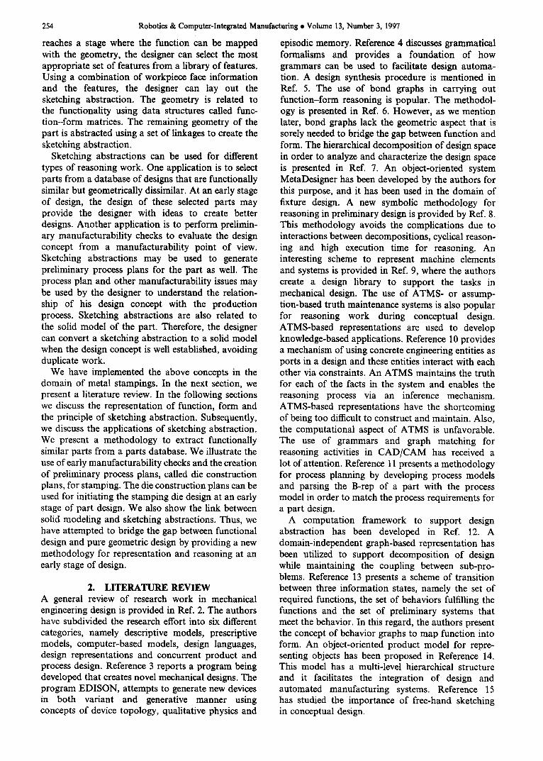
A large number of design decisions are made during the conceptual design of a part. However, there are few representation and reasoning tools for decision support during conceptual design. The conceptual design stage is characterized by a lack of complete geometric information. Existing geometric modelers require complete geometric information, while a functional reasoning methodology using a < verb, noun > representation is typically too terse. In this paper, we present a new representation called sketching abstraction for conceptual design, using the function- form relations in a design. The functionally critical part of the geometry is represented using a set of functional features, while the rest of the geometry is abstracted as a set of linkages. Part functionality is correlated with the sketching abstraction using data structures called function-form matrices. The sketching abstraction is annotated using a set of primitives, and a set of grammar rules are used to extract canonical relationships between the functional features. The sketching abstraction can be used for extracting designs that are geometrically dissimilar but functionally similar, thus providing the designer with ideas for design alternatives. The sketching abstraction can also be used to curry out domain-dependent manufacturability evaluation checks. A further use of sketching abstractions is to initiate the development of a process plan for manufacturing. Sketching abstractions are related to the solid model of a part. Thus, this representation provides a link between pure functional and pure geometric representations. The domain of application is stamped metal parts. We present the part functionality and the features used in this domain. We also illustrate the use of sketching abstractions for conceptual design, manufacturability evaluation and preliminary process planning. © 1997 Elsevier Science Ltd.
Keywords---conceptual design; representation; manufacturability; sketching abstraction; process planning; parsing; CAD/CAM/CIM
1. I N T R O D U C T I O N The use of CAD/CAM tools for design work has significantly improved designer's productivity and the quality of designs. However, most of the available CAD tools focus on the downstream activity of detailed design or assembly design. Detailed design is carried out after the design concept and geometry are well established. CAD/CAM tools help the designer in drafting work, FEM analysis, NC cutter path analysis, etc. However, the key design activity is the conceptual design stage, where the designer works with the functional requirements of a part. The functional requirements need to be decomposed, and at a certain stage the functionality has to be mapped to the geometry. This process is not a simple linear progression. The designer may update the functional decomposition, update the mapped geometry, proceed through iterations until
Correspondence should be addressed to: 2330 S. Canon Drive, Apt. 104, Mount Prospect, IL 60056, U.S.A.
253
the concept is well defined. The geometry is typically incomplete at this stage of design.
In this paper, we propose a new representation methodology which may be used as the schema for a CAD tool to support conceptual design of parts. This representation is called the sketching abstraction. The principle of the sketching abstraction is to represent the functionally essential parts of the geometry, using features and workpiece face in- formation. A simplified wireframe-based data struc- ture is used for this representation. The remaining geometry is abstracted using a linkage system. The sketching abstraction is annotated with a set of primitives. A grammar has been developed to extract canonical pairwise relationships between the func- tionally essential parts of the geometry. These relationships form the functional signature of the part.
Sketching abstractions have a close relationship with the part functionality. We have developed a group technology (GT) based coding schema for representing functions. Functional decomposition may be carried out by the designer using the principles of axiomatic design, l When the designer
254 Robotics & Computer-Integrated Manufacturing • Volume 13, Number 3, 1997
reaches a stage where the function can be mapped with the geometry, the designer can select the most appropriate set of features from a library of features. Using a combination of workpiece face information and the features, the designer can lay out the sketching abstraction. The geometry is related to the functionality using data structures called func- tion-form matrices. The remaining geometry of the part is abstracted using a set of linkages to create the sketching abstraction.
Sketching abstractions can be used for different types of reasoning work. One application is to select parts from a database of designs that are functionally similar but geometrically dissimilar. At an early stage of design, the design of these selected parts may provide the designer with ideas to create better designs. Another application is to perform prelimin- ary manufacturability checks to evaluate the design concept from a manufacturability point of view. Sketching abstractions may be used to generate preliminary process plans for the part as well. The process plan and other manufacturability issues may be used by the designer to understand the relation- ship of his design concept with the production process. Sketching abstractions are also related to the solid model of the part. Therefore, the designer can convert a sketching abstraction to a solid model when the design concept is well established, avoiding duplicate work.
We have implemented the above concepts in the domain of metal stampings. In the next section, we present a literature review. In the following sections we discuss the representation of function, form and the principle of sketching abstraction. Subsequently, we discuss the applications of sketching abstraction. We present a methodology to extract functionally similar parts from a parts database. We illustrate the use of early manufacturability checks and the creation of preliminary process plans, called die construction plans, for stamping. The die construction plans can be used for initiating the stamping die design at an early stage of part design. We also show the link between solid modeling and sketching abstractions. Thus, we have attempted to bridge the gap between functional design and pure geometric design by providing a new methodology for representation and reasoning at an early stage of design.
2. LITERATURE REVIEW A general review of research work in mechanical engineering design is provided in Ref. 2. The authors have subdivided the research effort into six different categories, namely descriptive models, prescriptive models, computer-based models, design languages, design representations and concurrent product and process design. Reference 3 reports a program being developed that creates novel mechanical designs. The program EDISON, attempts to generate new devices in both variant and generative manner using concepts of device topology, qualitative physics and
episodic memory. Reference 4 discusses grammatical formalisms and provides a foundation of how grammars can be used to facilitate design automa- tion. A design synthesis procedure is mentioned in Ref. 5. The use of bond graphs in carrying out function-form reasoning is popular. The methodol- ogy is presented in Ref. 6. However, as we mention later, bond graphs lack the geometric aspect that is sorely needed to bridge the gap between function and form. The hierarchical decomposition Of design space in order to analyze and characterize the design space is presented in Ref. 7. An object-oriented system MetaDesigner has been developed by the authors for this purpose, and it has been used in the domain of fixture design. A new symbolic methodology for reasoning in preliminary design is provided by Ref. 8. This methodology avoids the complications due to interactions between decompositions, cyclical reason- ing and high execution time for reasoning. An interesting scheme to represent machine elements and systems is provided in Ref. 9, where the authors create a design library to support the tasks in mechanical design. The use of ATMS- or assump- tion-based truth maintenance systems is also popular for reasoning work during conceptual design. ATMS-based representations are used to develop knowledge-based applications. Reference 10 provides a mechanism of using concrete engineering entities as ports in a design and these entities interact with each other via constraints. An ATMS maintains the truth for each of the facts in the system and enables the reasoning process via an inference mechanism. ATMS-based representations have the shortcoming of being too difficult to construct and maintain. Also, the computational aspect of ATMS is unfavorable. The use of grammars and graph matching for reasoning activities in CAD/CAM has received a lot of attention. Reference I l presents a methodology for process planning by developing process models and parsing the B-rep of a part with the process model in order to match the process requirements for a part design.
A computation framework to support design abstraction has been developed in Ref. 12. A domain-independent graph-based representation has been utilized to support decomposition of design while maintaining the coupling between sub-pro- blems. Reference 13 presents a scheme of transition between three information states, namely the set of required functions, the set of behaviors fulfilling the functions and the set of preliminary systems that meet the behavior. In this regard, the authors present the concept of behavior graphs to map function into form. An object-oriented product model for repre- senting objects has been proposed in Reference 14. This model has a multi-level hierarchical structure and it facilitates the integration of design and automated manufacturing systems. Reference 15 has studied the importance of free-hand sketching in conceptual design.
Conceptual design, manufacturability and process planning • A. MUKHERJEE and C. R. LIU
Feature-based design is a significant area in design research work. 16 The work in this field has been concentrated in characterizing features in various domains and in recognizing features from a CAD model. Research has only begun to represent geometry that is not well defined during conceptual design. Thus, the utility of this approach is limited to detailed design and process planning-related applica- tions at present. Reference 17 outlines a relative cost- based model to generate manufacturing costs for die construction. In all of the above representation methods, there is very little effort in trying to relate function with geometry during conceptual design. While geometry is incomplete during conceptual design, the designer can visualize the critical geometric elements. Hence, geometry should not be ignored for any kind of reasoning work during conceptual design. Our work presents a new methodology for the representation of the incomplete geometry and shows how it relates wi th the functional representation. We also show how this representation can be used for meaningful reasoning work.
3. R E P R E S E N T A T I O N OF PART F U N C T I O N Function is defined as the desired behavior of a part design in itself and in conjunction with other part designs in order to fulfil a user requirement. Every part design is a physical embodiment developed to satisfy a set of functions. The identification of a set of functions for the part is the first step in part design. This process is carried out using a hierarchical decomposition of functions into sub-functions. In addition, the process is iterative, wherein new functions may be added and decomposed sub- functions may be modified in order to reach a stage wherein the sub-functions can begin to get mapped with the part geometry. The process of developing functional representation to the point of initiating the physical design of the part is known as functional design. Therefore, a key aspect of conceptual design is the proper representation of part functionality.
While the functional decomposition process fol- lows a sequence of higher level functions being decomposed to intermediate and lower level sub- functions, the generic representation of a function is given as follows:
[< v >< n >< m >< d >< o >]loon < Keywords >
(1)
where the set v represents verbs, set n represents nouns, set m represents a magnitude attribute such as 10 N o f force, set d represents a direction attribute, and set o is another set o f nouns representing objects on which the function applies. The locn distinguishes between more than one similar functions, while Keywords is an additional set o f specialized words used to enhance the functional representation. Some of the above entities in a functional representation,
255
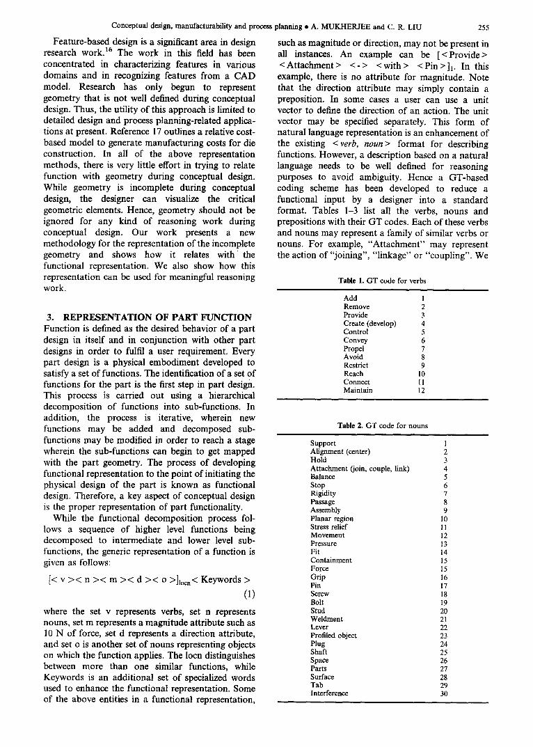
such as magnitude or direction, may not be present in all instances. An example can be [<Provide> < Attachment > <- > < with > < Pin > h. In this example, there is no attribute for magnitude. Note that the direction attribute may simply contain a preposition. In some cases a user can use a unit vector to define the direction of an action. The unit vector may be specified separately. This form of natural language representation is an enhancement of the existing < verb, noun> format for describing functions. However, a description based on a natural language needs to be well defined for reasoning purposes to avoid ambiguity. Hence a GT-based coding scheme has been developed to reduce a functional input by a designer into a standard format. Tables 1-3 list all the verbs, nouns and prepositions with their GT codes. Each of these verbs and nouns may represent a family of similar verbs or nouns. For example, "Attachment" may represent the action of "joining", "linkage" or "coupling". We
Table 1. GT code for verbs
Add 1 Remove 2 Provide 3 Create (develop) 4 Control 5 Convey 6 Propel 7 Avoid 8 Restrict 9 Reach 10 Connect I 1 Maintain 12
Table 2. GT code for nouns
Support Alignment (center) Hold Attachment (join, couple, link) Balance Stop Rigidity Passage Assembly Planar region Stress relief Movement Pressure Fit Containment Force Grip Pin Screw Bolt Stud Weldment Lever Profiled object Plug Shaft Space Parts Surface Tab Interference
1 2 3 4 5 6 7 8 9
10 11 12 13 14 15 15 16 17 18 19 20 21 22 23 24 25 26 27 28 29 30
256
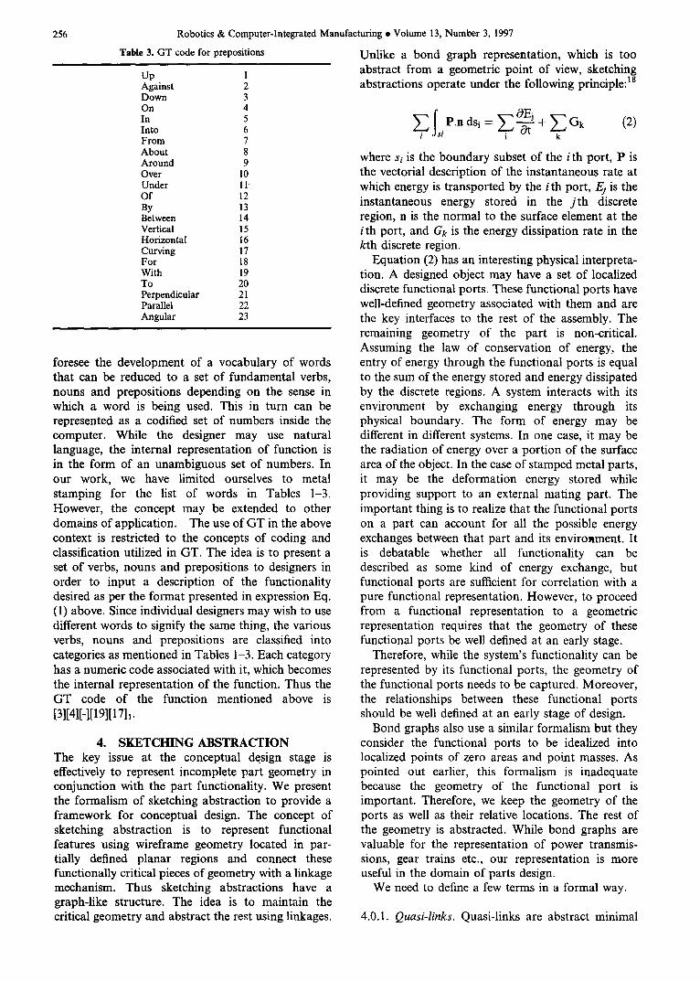
Table 3. GT code for prepositions
Up 1 Against 2 Down 3 On 4 In 5 Into 6 From 7 About 8 Around 9 Over ! 0 Under 11 Of 12 By 13 Between 14 Vertical 15 Horizontal 16 Curving 17 For 18 With 19 To 20 Perpendicular 21 Parallel 22 Angular 23
Robotics & Computer-Integrated Manufacturing • Volume 13, Number 3, 1997
Unlike a bond graph representation, which is too abstract from a geometric point of view, sketching abstractions operate under the following principle: Is
foresee the development of a vocabulary of words that can be reduced to a set of fundamental verbs, nouns and prepositions depending on the sense in which a word is being used. This in turn can be represented as a codified set of numbers inside the computer. While the designer may use natural language, the internal representation of function is in the form of an unambiguous set of numbers. In our work, we have limited ourselves to metal stamping for the list of words in Tables 1-3. However, the concept may be extended to other domains of application. The use of GT in the above context is restricted to the concepts of coding and classification utilized in GT. The idea is to present a set of verbs, nouns and prepositions to designers in order to input a description of the functionality desired as per the format presented in expression Eq. (1) above. Since individual designers may wish to use different words to signify the same thing, the various verbs, nouns and prepositions are classified into categories as mentioned in Tables 1-3. Each category has a numeric code associated with it, which becomes the internal representation of the function. Thus the GT code of the function mentioned above is [3][4][-][19][1711.
4. SKETCHING ABSTRACTION The key issue at the conceptual de.sign stage is effectively to represent incomplete part geometry in conjunction with the part functionality. We present the formalism of sketching abstraction to provide a framework for conceptual design. The concept of sketching abstraction is to represent functional features using wireframe geometry located in par- tially defined planar regions and connect these functionally critical pieces of geometry with a linkage mechanism. Thus sketching abstractions have a graph-like structure. The idea is to maintain the critical geometry and abstract the rest using linkages.
/IsiP.ndsi= G k (2)
where si is the boundary subset of the ith port, P is the vectorial description of the instantaneous rate at which energy is transported by the i th port, Ej is the instantaneous energy stored in the j t h discrete region, n is the normal to the surface element at the ith port, and Gk is the energy dissipation rate in the kth discrete region.
Equation (2) has an interesting physical interpreta- tion. A designed object may have a set of localized discrete functional ports. These functional ports have well-defined geometry associated with them and are the key interfaces to the rest of the assembly. The remaining geometry of the part is non-critical. Assuming the law of conservation of energy, the entry of energy through the functional ports is equal to the sum of the energy stored and energy dissipated by the discrete regions. A system interacts with its environment by exchanging energy through its physical boundary. The form of energy may be different in different systems. In one case, it may be the radiation of energy over a portion of the surface area of the object. In the case of stamped metal parts, it may be the deformation energy stored while providing support to an external mating part. The important thing is to realize that the functional ports on a part can account for all the possible energy exchanges between that part and its environment. It is debatable whether all functionality can be described as some kind of energy exchange, but functional ports are sufficient for correlation with a pure functional representation. However, to proceed from a functional representation to a geometric representation requires that the geometry of these functional ports be well defined at an early stage.
Therefore, while the system's functionality can be represented by its functional ports, the geometry of the functional ports needs to be captured. Moreover, the relationships between these functional ports should be well defined at an early stage of design.
Bond graphs also use a similar formalism but they consider the functional ports to be idealized into localized points of zero areas and point masses. As pointed out earlier, this formalism is inadequate because the geometry of the functional port is important. Therefore, we keep the geometry of the ports as well as their relative locations. The rest of the geometry is abstracted. While bond graphs are valuable for the representation of power transmis- sions, gear trains etc., our representation is more useful in the domain of parts design.
We need to define a few terms in a formal way.
4.0.1. Quasi-links. Quasi-links are abstract minimal
Conceptual design, manufacturability and process planning • A. MUKHERJEE and C. R. LIU
linkages between the reference points between two features. Therefore, given two or more functional features, a quasi-link is the shortest connection between any two functional features.
There can be two forms of quasi-links. Strong quasi-link is used to connect two functional features if the minimal connection between them is over a solid continuum. By default, quasi-links are straight lines. Weak quasi-link is used to designate a special geometric relationship between two features, such as concentricity, angularity, parallelism, perpendicular- ity etc.
The formal definition of a strong quasi-link is:
Iv = < )~, vi, vj, A• > (3)
where l o. is a strong quasi-link, vi is the vector to the first reference point from a global origin, vj is the vector to the second reference point from a global origin, Aij is a set of attributes, and 2 is a type flag.
The set of attributes may be used to place tolerance relationships between features. The type flag distinguishes if the link is a regular quasi-link or a quasi-link connecting an entity to a bend/form in a part.
The formal representation of a weak quasi-link is as follows:
l, 7' --< 2, vi, b, A,j > (4)
where Iv: is a weak quasi-link, v; is the vector to the first reference point, vj is the vector to the second reference point, A# is a set of attributes, and 2 is a type flag.
In the case of weak quasi-links, the set of attributes essentially correspond to geometric constraints, as explained later, and the type flag associates an integer value with each type of attribute.
257
surface. Their function is that of containers that contain a set of features for a surface of the stamped part.
The generic description of a forming node is given as follows:
n f = < v, PRI, PRj, o~0. , lij, < hij >> (5)
where W is the forming node, PRg is the first planar region, PRj is the second planar region, aq is the bend angle, l~ is the length of the bend, and < h~ > is the set of flange heights.
Each forming node contains pointers to each of the planar regions it is connected to. In addition, it also stores the properties at that bend node such as bend angle, bend length and a set of flange heights, if the flange height is variable. A regular quasi-node on a planar region only has the vector location and a pointer to the planar region containing the quasi- node.
4.0.4. Sketching abstraction A sketching abstraction is the minimal representa-
tion of a design object using functional features, quasi-links and quasi-nodes so as to provide an intermediate representation between the pure geo- metric and pure functional form
SAi = FFi, qtinksi, qnodesi, qnodes~ (6)
where SAi is the ith sketching abstraction, FFi is the ith set of functional features, q_linksiis the ith set of quasi-links, q_node& is the ith set of quasi-nodes, and q_nodesli is the ith set of forming nodes.
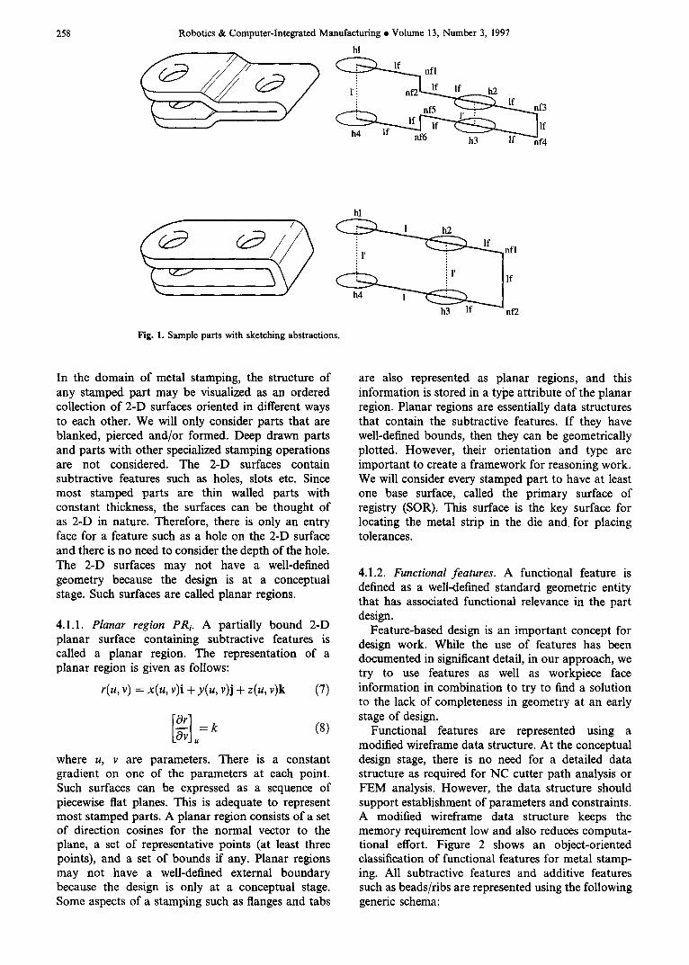
Figure 1 shows stamped parts with their sketching abstraction. Such a representation can then be used to reason about alternative generation in design.
4.0.2. Quasi-nodes. Abstract nodes between two or more quasi-links or an object edge with a quasi-link are called quasi-nodes. They represent a change point in the geometry of the quasi-linkage between functional features. A change point represents a place on the part geometry where there is a significant change in the geometry, e.g. for a bend on a part.
4.0.3. Forming nodes. A bend in a part profile is represented using a special set of quasi-nodes called forming nodes. They are represented as q_nodef. The quasi-links connecting other entities to the forming nodes are also marked with a forming designation fl
The formal definition of a forming node requires the concept of a planar region. Planar regions will be mathematically defined in the next section. Basically they are partially bound two-dimensional (2-D) planar surfaces containing subtractive features. For the stamping domain application, planar regions have a constant gradient on one of the parameters used in the parametric representation of a generic
4.1. Representation of form During conceptual design, the decomposition of function reaches a stage where the designer begins to map the lower level functions with part geometry. The geometry at this point is not the entire geometry of the part. It is the functionally critical parts of the entire part geometry. The rest of the part geometry may be undecided at this point. The decomposition of function and the mapping to geometry is not a linear process. Functional decomposition may be modified, added or deleted. The mapped geometry may also be modified, added or deleted. Therefore, the requirement for a computer tool is to enable the representation of functionally essential parts of the geometry so that the geometry has a correspondence with the part functionality. Moreover, there must be connections between the essential parts of the geometry, as per the sketching abstraction. These connections should be easily updated. Moreover, the connections should also allow meaningful reasoning work in order to provide any help to the designer.
The form representation is done using a combina- tion of features and face information in a workpiece.
258 Robotics & Computer-Integrated Manufacturing • Volume 13, Number 3, 1997
hl
hi
• 1' ~ n f l
i 1' lie h4 1 ~
h3 If nf2
Fig. 1. Sample parts with sketching abstractions.
In the domain of metal stamping, the structure of any stamped part may be visualized as an ordered collection of 2-D surfaces oriented in different ways to each other. We will only consider parts that are blanked, pierced and/or formed. Deep drawn parts and parts with other specialized stamping operations are not considered. The 2-D surfaces contain subtractive features such as holes, slots etc. Since most stamped parts are thin walled parts with constant thickness, the surfaces can be thought of as 2-D in nature. Therefore, there is only an entry face for a feature such as a hole on the 2-D surface and there is no need to consider the depth of the hole. The 2-D surfaces may not have a well-defined geometry because the design is at a conceptual stage. Such surfaces are called planar regions.
4.1.1. Planar region PRi. A partially bound 2-D planar surface containing subtractive features is called a planar region. The representation of a planar region is given as follows:
r(u, v) = x(u, v)i + y(u, v)j + z(u, v)k (7)
]u= g (8)
where u, v are parameters. There is a constant gradient on one of the parameters at each point. Such surfaces can be expressed as a sequence of piecewise fiat planes. This is adequate to represent most stamped parts. A planar region consists of a set of direction cosines for the normal vector to the plane, a set of representative points (at least three points), and a set of bounds if any. Planar regions may not have a well-defined external boundary because the design is only at a conceptual stage. Some aspects of a stamping such as flanges and tabs
are also represented as planar regions, and this information is stored in a type attribute of the planar region. Planar regions are essentially data structures that contain the subtractive features. If they have well-defined bounds, then they can be geometrically plotted. However, their orientation and type are important to create a framework for reasoning work. We will consider every stamped part to have at least one base surface, called the primary surface of registry (SOR). This surface is the key surface for locating the metal strip in the die and. for placing tolerances.
4.1.2. Functional features. A functional feature is defined as a well-defined standard geometric entity that has associated functional relevance in the part design.
Feature-based design is an important concept for design work. While the use of features has been documented in significant detail, in our approach, we try to use features as well as workpiece face information in combination to try to find a solution to the lack of completeness in geometry at an early stage of design.
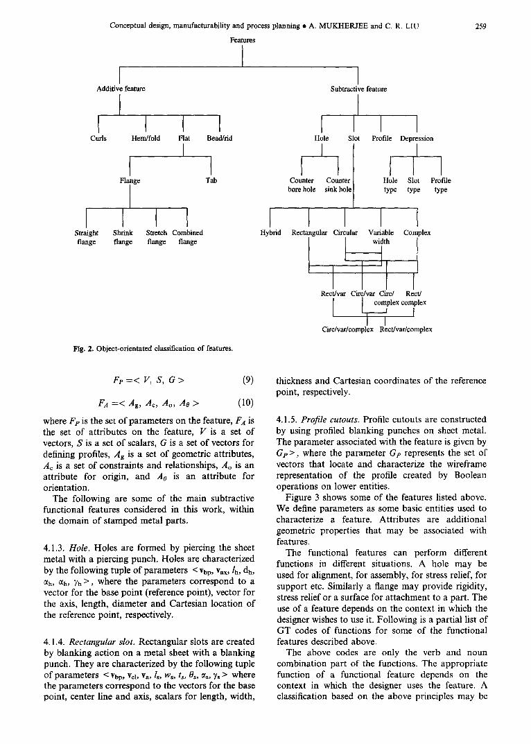
Functional features are represented using a modified wireframe data structure. At the conceptual design stage, there is no need for a detailed data structure as required for NC cutter path analysis or FEM analysis. However, the data structure should support establishment of parameters and constraints. A modified wireframe data structure keeps the memory requirement low and also reduces computa- tional effort. Figure 2 shows an object-oriented classification of functional features for metal stamp- ing. All subtractive features and additive features such as beads/ribs are represented using the following generic schema:
Conceptual design, manufacturability and process planning • A. MUKHERJEE and C, R. LIU
Features
I I I Additive feature Subtractive feature
Flange Tab
Straight Shrink Stretch Combined flange flange flange flange
P Curls Hem/fold Flat Bead/rid Hole Slot
I I I I
Counter Counter bore hole sink hole
I I Profile Depression
I
Hole Slot Pmfde type type type
I Hybrid
I Rectangular Circular
I Rect/var Circ/var Circ/
Variable width
Complex
I Rect/
complex complex I LI, Circ/var/complex Recffvar/complex
Fig. 2. Object-orientated classification of features.
259
Fe = < V, S, G > (9)
FA = < Ag, Ae, Ao, Ao > (I0)
where Fp is the set of parameters on the feature, FA is the set of attributes on the feature, V is a set of vectors, S is a set of scalars, G is a set of vectors for defining profiles, Ag is a set of geometric attributes, Ac is a set of constraints and relationships, Ao is an attribute for origin, and Ao is an attribute for orientation.
The following are some of the main subtractive functional features considered in this work, within the domain of stamped metal parts.
4.1.3. Hole. Holes are formed by piercing the sheet metal with a piercing punch. Holes are characterized by the following tuple of parameters < Vbp, Vax, lh, dh, (~h, ah, ~)h >, where the parameters correspond to a vector for the base point (reference point), vector for the axis, length, diameter and Cartesian location of the reference point, respectively.
4.1,4. Rectangular slot. Rectangular slots are created by blanking action on a metal sheet with a blanking punch. They are characterized by the following tuple of parameters < Vbp, vcl, Va, Is, W~, t,, 08, ~ , Ys > where the parameters correspond to the vectors for the base point, center line and axis, scalars for length, width,
thickness and Cartesian coordinates of the reference point, respectively.
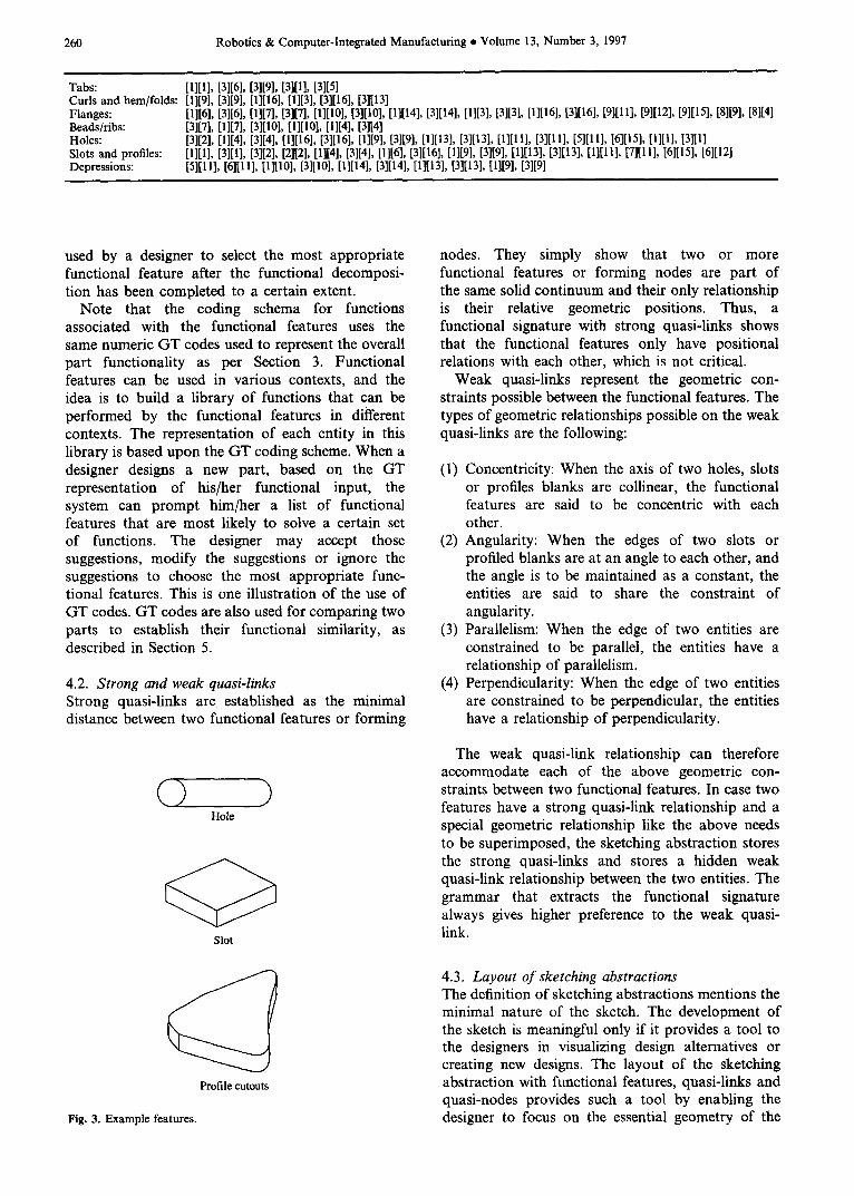
4.1.5. Profile cutouts. Profile cutouts are constructed by using profiled blanking punches on sheet metal. The parameter associated with the feature is given by Gv >, where the parameter G? represents the set of vectors that locate and characterize the wireframe representation of the profile created by Boolean operations on lower entities.
Figure 3 shows some of the features listed above. We define parameters as some basic entities used to characterize a feature. Attributes are additional geometric properties that may be associated with features.
The functional features can perform different functions in different situations. A hole may be used for alignment, for assembly, for stress relief, for support etc. Similarly a flange may provide rigidity, stress relief or a surface for attachment to a part. The use of a feature depends on the context in which the designer wishes to use it. Following is a partial list of GT codes of functions for some of the functional features described above.
The above codes are only the verb and noun combination part of the functions. The appropriate function of a functional feature depends on the context in which the designer uses the feature. A classification based on the above principles may be
260 Robotics & Computer-Integrated Manufacturing • Volume 13, Number 3, 1997
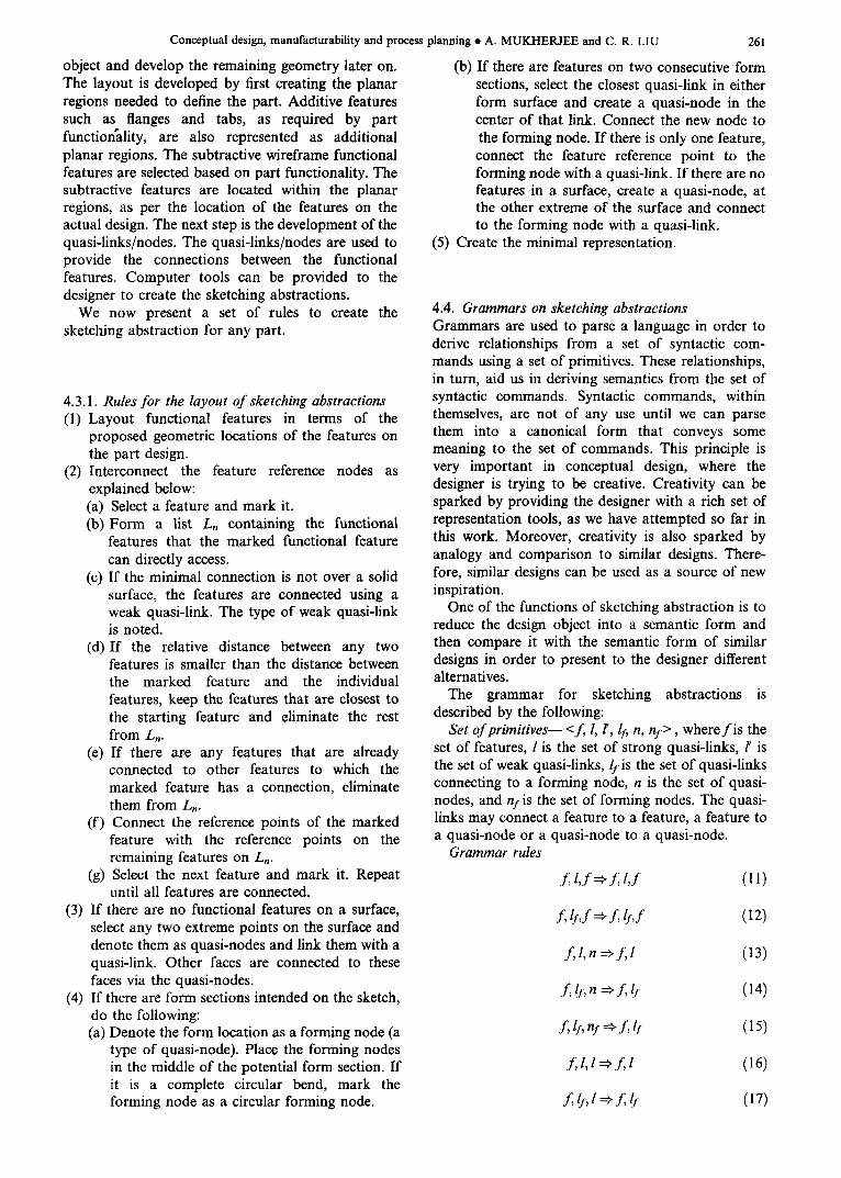
Tabs: [1][1], [3116], [3119], [31111, [3][51 Curls and hem/folds: [1119], [3][9], [1]116], [1][3], [3][16], [3][13] Flanges: [1][6], [3][6], [1][7], [3][7], [1][10], [3][10], [1][14], [3][14], [1][3], [3][3], [I][16], [3][16], [9][11], [9][12], [9][15], [8][9], [8][41 Beads/ribs: [3][7], [1][7], [3][10], [1][10], [1][4], [3][4] Holes: [3][2], [I][4], [3][4], [11[16], [3l[16], [1][9], [3][9], [1][13], [3][13], [1][11], [3][11], [5][11], [6][15], ll][l], 13][ll Slots and profiles: [1][1], [3][1], [3]12], [2][2], [1][4], [3][4], [I][6], [3][16], [1][9], [3][9], [1][13l, [3][13], [1][11], [7][1 I], [6][15], [6][12] Depressions: [5][11], [6][11], [ll[10], [3][10], [1][14], [3][14], [1][i 3], [3][13], [1][9], [3][9]
used by a designer to select the most appropriate functional feature after the functional decomposi- tion has been completed to a certain extent.
Note that the coding schema for functions associated with the functional features uses the same numeric GT codes used to represent the overall part functionality as per Section 3. Functional features can be used in various contexts, and the idea is to build a library of functions that can be performed by the functional features in different contexts. The representation of each entity in this library is based upon the GT coding scheme. When a designer designs a new part, based on the GT representation of his/her functional input, the system can prompt him/her a list of functional features that are most likely to solve a certain set of functions. The designer may accept those suggestions, modify the suggestions or ignore the suggestions to choose the most appropriate func- tional features. This is one illustration of the use of GT codes. GT codes are also used for comparing two parts to establish their functional similarity, as described in Section 5.
4.2. Strong and weak quasi-links Strong quasi-links are established as the minimal distance between two functional features or forming
(3 ) Hole
Slot
Profile cutouts
Fig. 3. Example features.
nodes. They simply show that two or more functional features or forming nodes are part of the same solid continuum and their only relationship is their relative geometric positions. Thus, a functional signature with strong quasi-links shows that the functional features only have positional relations with each other, which is not critical.
Weak quasi-links represent the geometric con- straints possible between the functional features. The types of geometric relationships possible on the weak quasi-links are the following:
(1) Concentricity: When the axis of two holes, slots or profiles blanks are collinear, the functional features are said to be concentric with each other.
(2) Angularity: When the edges of two slots or profiled blanks are at an angle to each other, and the angle is to be maintained as a constant, the entities are said to share the constraint of angularity.
(3) Parallelism: When the edge of two entities are constrained to be parallel, the entities have a relationship of parallelism.
(4) Perpendicularity: When the edge of two entities are constrained to be perpendicular, the entities have a relationship of perpendicularity.
The weak quasi-link relationship can therefore accommodate each of the above geometric con- straints between two functional features. In case two features have a strong quasi-link relationship and a special geometric relationship like the above needs to be superimposed, the sketching abstraction stores the strong quasi-links and stores a hidden weak quasi-link relationship between the two entities. The grammar that extracts the functional signature always gives higher preference to the weak quasi- link.
4.3. Layout of sketching abstractions The definition of sketching abstractions mentions the minimal nature of the sketch. The development of the sketch is meaningful only if it provides a tool to the designers in visualizing design alternatives or creating new designs. The layout of the sketching abstraction with functional features, quasi-links and quasi-nodes provides such a tool by enabling the designer to focus on the essential geometry of the
Conceptual design, manufacturability and process planning
object and develop the remaining geometry later on. The layout is developed by first creating the planar regions needed to define the part. Additive features such as flanges and tabs, as required by part functionality, are also represented as additional planar regions. The subtractive wireframe functional features are selected based on part functionality. The subtractive features are located within the planar regions, as per the location of the features on the actual design. The next step is the development of the quasi-links/nodes. The quasi-links/nodes are used to provide the connections between the functional features. Computer tools can be provided to the designer to create the sketching abstractions.
We now present a set of rules to create the sketching abstraction for any part.
4.3.1. Rules for the layout of sketching abstractions (1) Layout functional features in terms of the
proposed geometric locations of the features on the part design.
(2) Interconnect the feature reference nodes as explained below: (a) Select a feature and mark it. (b) Form a list Ln containing the functional
features that the marked functional feature can directly access.
(c) If the minimal connection is not over a solid surface, the features are connected using a weak quasi-link. The type of weak quasi-link is noted.
(d) If the relative distance between any two features is smaller than the distance between the marked feature and the individual features, keep the features that are closest to the starting feature and eliminate the rest from L,.
(e) If there are any features that are already connected to other features to which the marked feature has a connection, eliminate them from L~.
(f) Connect the reference points of the marked feature with the reference points on the remaining features on L~.
(g) Select the next feature and mark it. Repeat until all features are connected.
(3) If there are no functional features on a surface, select any two extreme points on the surface and denote them as quasi-nodes and link them with a quasi-link. Other faces are connected to these faces via the quasi-nodes.
(4) If there are form sections intended on the sketch, do the following: (a) Denote the form location as a forming node (a
type of quasi-node). Place the forming nodes in the middle of the potential form section. If it is a complete circular bend, mark the forming node as a circular forming node.
• A. MUKHERJEE and C. R. LIU 261
(b) If there are features on two consecutive form sections, select the closest quasi-link in either form surface and create a quasi-node in the center of that link. Connect the new node to the forming node. If there is only one feature, connect the feature reference point to the forming node with a quasi-link. I f there are no features in a surface, create a quasi-node, at the other extreme of the surface and connect to the forming node with a quasi-link.
(5) Create the minimal representation.
4.4. Grammars on sketching abstractions Grammars are used to parse a language in order to derive relationships from a set of syntactic com- mands using a set of primitives. These relationships, in turn, aid us in deriving semantics from the set of syntactic commands. Syntactic commands, within themselves, are not of any use until we can parse them into a canonical form that conveys some meaning to the set of commands. This principle is very important in conceptual design, where the designer is trying to be creative. Creativity can be sparked by providing the designer with a rich set of representation tools, as we have attempted so far in this work. Moreover, creativity is also sparked by analogy and comparison to similar designs. There- fore, similar designs can be used as a source of new inspiration.
One of the functions of sketching abstraction is to reduce the design object into a semantic form and then compare it with the semantic form of similar designs in order to present to the designer different alternatives.
The grammar for sketching abstractions is described by the following:
Set of primitives-- < f, l, l', If, n, nr>, where f i s the set of features, l is the set of strong quasi-links, l' is the set of weak quasi-links,/r is the set of quasi-links connecting to a forming node, n is the set of quasi- nodes, and nf is the set of forming nodes. The quasi- links may connect a feature to a feature, a feature to a quasi-node or a quasi-node to a quasi-node.
Grammar rules
f , l , f ~ . ~ l , f (11)
f , l f , f ~ f, lf, f (12)
f , l , n ~ f , l (13)
f, lf, n ~ f,I[ (14)
f,9,nz f,b (15)
f , l , l ~ f , l (16)
f , l f , z,,- (17)
262 Robotics & Computer-Integrated Manufacturing • Volume 13, Number 3, 1997
f,l, f, lf (18)
f, lf,& f,& (19)
f , l ' , f =*. f , f , f (20)
n,l,n ~ n (21)
nf, l, n ::¢, nf (22)
n , l , f ~ f (23)
n , f =~ f (24)
f , l, f and f , f , f =~ f , l ' , f (25)
f~,l,f2 and f2,l,f3 =~ ft , l , f3 (26)
f l , lf,f2 and f2, l,f3 ~ f l , If, f3 (27)
f l , l,f2 and f2, Iff, f3 =¢" f l , lf, f3 (28)
f t , lf, f2 and fz,/f, f3 =~ft, lf, f3. (29)
These grammar rules are a subset of the overall set of grammar rules possible. The rules can be used to annotate and parse the sketching abstraction in order to obtain a canonical representation of the sketch called the functional signature.
4.4.1. Functional signature. The functional signature of a design sketch is the parsed grammar relationship between each pair of functional features.
The grammar rules have been derived with the motivation of extracting pairwise canonical relation- ships between features. The relations are of three types namely l, l' and !r corresponding to a strong quasi-link, weak quasi-link or a forming relationship. Rules 7-20 show various ways to reduce the sequence of annotations between a pair of functional features to one label. Rules 21-25 provide the combined effect of two pairwise canonical relationships. The effect of all the rules is that two features which do not have a direct connection over the sketching abstraction can get related. The canonical relationships can have various associated information, such as constraints or tolerances.
4.4.2. Algorithm for parsing sketching abstractions
(1) Annotate the features of the sketching abstrac- tion, in terms of the features, quasi-nodes and quasi-links. For slot features, label as s;, where s is the block feature and i is the sequence number. For hole feature, mark with hi, where h is the hole feature and j is the sequence number. For
profiles, label with Pk, where P is the user defined feature and k is the sequence number.
(2) For each pair of features, span the sketch and extract the syntactic relationship such as h flnlnlnlnh2.
(3) For each pair of features, reduce the syntactic relationship using the grammar developed above to its most simple form. In the example this will become hflh2. For an l' relationship, the type such as concentricity, angularity etc. is also stored in the functional signature.
(4) A set of these canonical relationships between the features form the functional signature. This signature may be used to extract similar designs.
The key idea in the above algorithm is that the important functional pieces of geometry in the design object are linked to each other via some canonical relationships, no matter how the overall geometry may look. By distilling a functional signature, we can compare two parts which may be quite different from a geometric point of view, yet are similar in functionality. This is the objective of sketching. It allows us to represent the functional parts of the geometry and visualize the alternatives for the overall geometry. Moreover, similar parts which have the same functionality can be compared to get novel ideas for new designs. Ordinary geometric models do not enable us to compare designs that have significant design dissimilarity.
The process of creating a sketching abstraction is non-unique. Therefore, different designers may create different sketching abstractions to designate the same designs. It all depends upon which sequence of surfaces and functional features are used by the designer in developing a sketch. However, the basic functional concept of the design is an invariant, i.e. the functional requirement of the part, the special geometric constraints desired, the tolerances expected remain the same. Therefore, the functional signature is a way to generate a unique representation from the non-unique sketching abstraction. We accomplish this by developing a set of pairwise relationships between every pair of functional features, including subtractive and additive features. The pairwise relation is created by annotating the sketching abstraction with primitives and using grammar rules to parse a sequence of primitives. Therefore, one relationship may indicate that both features need to be on the same surface, while another may indicate that two features should reside on separate surfaces. One relationship may indicate a special geometric relation, such as concentricity of two features, while another relation may indicate tolerance stacking. The priority of the grammar rules are such that special relations such as geometric relations and tolerances get a higher priority than simply positional relations between two features. Since functional features map with the functions specified by the designer earlier, a pairwise relation between functional features is also
Conceptual design, manufacturability and process planning • A. MUKHERJEE and C. R. LIU
representative of the interaction between two or more functionalities desired from the part. This informa- tion can be used to determine which aspects of the design concept's geometry is tightly coupled. While this may seem fairly simple from a visual inspection of the sketching abstraction, the idea is automate the process and use computer software to understand the functional semantics of a preliminary design in order to evaluate the design concept.
The entire process of annotation and parsing the grammar, is transparent to the designers. The designer inputs the functionality desired, the func- tional features, planar regions and special relation- ships between features. The algorithm automatically creates the graph of features, labels the graph and parses the functional signature for further analysis.
4.4.3. Transitivity of canonical relationships. Each of the canonical relationships deduced from the algo- rithm outlined above possesses the property of transitivity. Therefore, if we have fl/f2, it is the same as f2/fl where,- is any of the functional features and the relationships are of the form l, l' or/~
4.5. Function-form matrices In this section, we analyze the correspondence between the functional features on a sketch with the functions provided by the part in the assembly. Function-form relations are always many-many in nature. This means that there may be one feature/ part that performs multiple functions or a combina- tion of features or parts that perform a function. Therefore, we introduce the data structure of function-form matrices to provide the relationship between a functional decomposition and the sketch- ing abstraction of the parts. Please note that in the following discussion, functions are assumed to be represented as described earlier.
There are two kinds of function-form matrices that we will consider. The first one is at the product level and the form corresponds to the individual parts in the product. The second one is at the part level, and the form corresponds to the functional features on the sketching abstraction of the part. The functions at the part level matrix are subfunctions of those at the product level matrix.
263
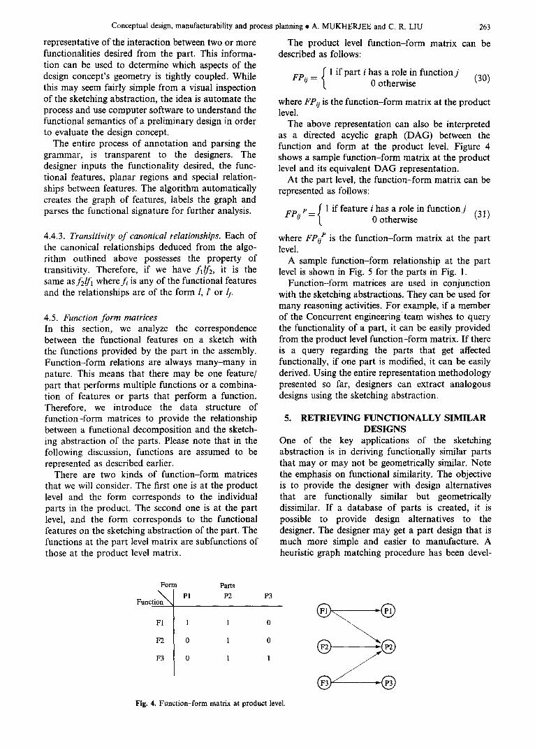
The product level function-form matrix can be described as follows:
f 1 if part i has a role in function j FPij (30) / 0 otherwise
where FPij is the function-form matrix at the product level.
The above representation can also be interpreted as a directed acyclic graph (DAG) between the function and form at the product level. Figure 4 shows a sample function-form matrix at the product level and its equivalent DAG representation.
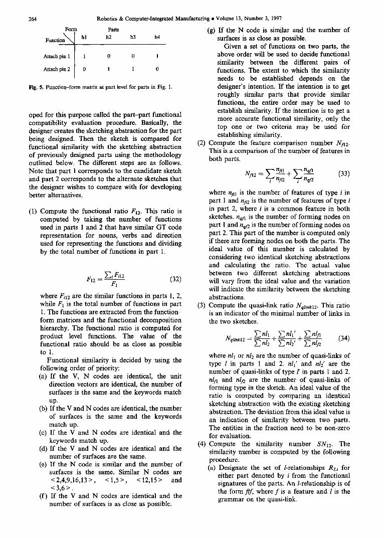
At the part level, the function-form matrix can be represented as follows:
FPoe= { 1 if feature i0haSotherwisea role in function j (31)
where FPo P is the function-form matrix at the part level.
A sample function-form relationship at the part level is shown in Fig. 5 for the parts in Fig. 1.
Function-form matrices are used in conjunction with the sketching abstractions. They can be used for many reasoning activities. For example, if a member of the Concurrent engineering team wishes to query the functionality of a part, it can be easily provided from the product level function-form matrix. If there is a query regarding the parts that get affected functionally, if one part is modified, it can be easily derived. Using the entire representation methodology presented so far, designers can extract analogous designs using the sketching abstraction,
5. RETRIEVING FUNCTIONALLY SIMILAR DESIGNS
One of the key applications of the sketching abstraction is in deriving functionally similar parts that may or may not be geometrically similar. Note the emphasis on functional similarity. The objective is to provide the designer with design alternatives that are functionally similar but geometrically dissimilar. If a database of parts is created, it is possible to provide design alternatives to the designer. The designer may get a part design that is much more simple and easier to manufacture. A heuristic graph matching procedure has been devel-
Fol'm
Function~x
F1
F2
F3
Parts P1 P2 P3
1 1 0
0 1 0
0 1 1
Fig. 4. Function-form matrix at product level.
264
Form
Funct ion~ hl
Attach pinl I 1
Attach pin2[ 0
Robotics & Computer-Integrated Manufacturing s Volume 13, Number 3, 1997
Parts h2 h3 h4
0 0 1
1 1 0
Fig. 5. Function-form matrix at part level for parts in Fig. 1.
oped for this purpose called the part-part functional compatibility evaluation procedure. Basically, the designer creates the sketching abstraction for the part being designed. Then the sketch is compared for functional similarity with the sketching abstraction of previously designed parts using the methodology outlined below. The different steps are as follows. Note that part 1 corresponds to the candidate sketch and part 2 corresponds to the alternate sketches that the designer wishes to compare with for developing better alternatives.
(1) Compute the functional ratio Fl2. This ratio is computed by taking the number of functions used in parts 1 and 2 that have similar GT code representation for nouns, verbs and direction used for representing the functions and dividing by the total number of functions in part 1.
Fl2 = ~-']4 g i l2 (32) F1
where Fil 2 are the similar functions in parts l, 2, while Fl is the total number of functions in part 1. The functions are extracted from the function- form matrices and the functional decomposition hierarchy. The functional ratio is computed for product level functions. The value of the functional ratio should be as close as possible to 1.
Functional similarity is decided by using the following order of priority: (a) If the V, N codes are identical, the unit
direction vectors are identical, the number of surfaces is the same and the keywords match up.
(b) If the V and N codes are identical, the number of surfaces is the same and the keywords match up.
(c) If the V and N codes are identical and the keywords match up.
(d) If the V and N codes are identical and the number of surfaces are the same.
(e) If the N code is similar and the number of surfaces is the same. Similar N codes are <2,4,9,16,13>, <1 ,5> , <12,15> and <3 ,6> .
(f) If the V and N codes are identical and the number of surfaces is as close as possible.
(g) If the N code is similar and the number of surfaces is as close as possible.
Given a set of functions on two parts, the above order will be used to decide functional similarity between the different pairs of functions. The extent to which the similarity needs to be established depends on the designer's intention. If the intention is to get roughly similar parts that provide similar functions, the entire order may be used to establish similarity. If the intention is to get a more accurate functional similarity, only the top one or two criteria may be used for establishing similarity.
(2) Compute the feature comparison number Nya2. This is a comparison of the number of features in both parts.
N~2 = ~-~n" + ~i a2 . (33)
where nil1 is the number of features of type i in part 1 and nil2 is the number of features of type i in part 2, where i is a common feature in both sketches, nqta is the number of forming nodes on part 1 and nql2 is the number of forming nodes on part 2. This part of the number is computed only if there are forming nodes on both the parts. The ideal value of this number is calculated by considering two identical sketching abstractions and calculating the ratio. The actual value between two different sketching abstractions will vary from the ideal value and the variation will indicate the similarity between the sketching abstractions.
(3) Compute the quasi-link ratio Nqli,,kx2. This ratio is an indicator of the minimal number of links in the two sketches.
E nil E nil' E nl~ (34) Nql,,kt2 : ~ 2 2 + ~ + E nlf2
where nli or n12 are the number of quasi-links of type l in parts 1 and 2. nll' and n12' are the number of quasi-links of type l' in parts 1 and 2. n/.~ and n!n are the number of quasi-links of forming type in the sketch. An ideal value of the ratio is computed by comparing an identical sketching abstraction with the existing sketching abstraction. The deviation from this ideal value is an indication of similarity between two parts. The entities in the fraction need to be non-zero for evaluation.
(4) Compute the similarity number SN12. The similarity number is computed by the following procedure. (a) Designate the set of /-relationships RL; for
either part denoted by i from the functional signatures of the parts. An/-relationship is of the form flf, where f is a feature and l is the grammar on the quasi-link.
Conceptual design, manufaeturability and process planning • A. MUKHERJEE and C. R. LIU
(b) Designate a similar set of/'-relationships Rm for either part denoted by i from the functional signatures of the parts.
(c) Designate a similar set of (t-relationships RLfi for either part denoted by i from the functional signatures of the parts.
(d) Develop a function mapping between the two sketching abstractions as follows:
(i) Compare the product level GT code representation for the functions.
(ii) Match functions using the priority for comparing functions.
(iii) For each function mapped, identify the part level functions and the features corresponding to them in the sketching abstraction. These features are mapped to each other and will be represented as
A ~f2. (e) For each Rzl and every Rm, count = 0.
(i) Rzl =fAllfBl and R m = f a2lf s2
(ii) I f fa l ----fro and fro -fs2, and the features are geometrically identical, count=- count+2. If the features are similar, i.e. share a common parent class in the object-oriented hierarchy of features, increment count by 1. Remove the relation from Rm.
(iii) Continue until there are no RL~ left. (f) For each RL, I and every Rz,z, countl =0.
(i) RL'I =fAll'fsl and Rz, = f A2l'f s2
(ii) IffA1 ~fa2 and fs l ~fsz, the type of l' relationship is the same and the features are geometrically identical, countl =countl +2. If the features are similar, increment count by 1. Remove the relation from RL'2.
(iii) Continue until there are no R/:l left. (g) For each Rzfl and every Rz4z, count2 = 0.
(i) RLfl =fAllffsl and RLI2=fA2lffB2 (ii) IffA1 ~faz and fro ~ f ~ , and the features
are geometrically identical, count2 =- count2+2. If the features are similar, increment count by 1. Remove the relation from RLf2.
(iii) Continue until there are no Rz42 left. (h) SN = count + countl + count2
The above procedure systematically prunes the search space by using some of the heuristic measures outlined to select good candidate designs. The last step for calculating the similarity number is where the functional signature is used. An ideal value is first computed by comparing the sketching abstraction under consideration with an identical sketching abstraction. Other parts will deviate from this ideal value of the similarity number and that will be an indication of the similarity between the parts. Thus, a database of sketching abstractions can be system-
265
atically evaluated with the proposed sketching abstraction and similar designs identified as possible design alternatives.
Although graph matching is not a polynomial time problem, the sparseness of our representation and the heuristics presented above reduce the matching effort to a polynomial time problem. The first heuristic compares the functional similarity between two sketching abstractions. However, this can result in a large number of candidates satisfying all or some of the functionality desired. Hence, the remaining heuristics compare the geometric complexity of the sketching abstractions to select a set that would be most productive for the designer to evaluate.
5.1. Computational complexity The computational complexity of the above proce- dure can be computed easily. The procedure to develop the functional signature is of the order of O(n 2) in computational complexity, where n is the number of functional features. If there is a design being developed and there is a candidate design, the exhaustive search of all functional relationships in one design with the other is no more than an exhaustive combination of the two functional signatures. This is of the form of O(n 4) in computational complexity. If there are C; candidates to compare, the complexity is O(Cin4). Since Ci is a constant, the computational complexity is still the fourth power of n.
5.2. Developing design alternatives There are three methods of generating design alternatives using the sketching abstraction. The first is to extract the parameters of the functional features and modify them appropriately. The second is to modify any weak quasi-link relationship by modifying the type of relationship. For example, relaxing a certain constraint between two functional features can result in significant difference in a design alternative. The third is to compare the sketching abstractions of a part with the available sketching abstractions of parts in a database, as described previously. This can provide a designer with better ideas, as he can see a prior design and get some kind of inspiration to create a new design.
6. MANUFACTURABILITY CHECKS WITH SKETCHING ABSTRACTIONS
During the conceptual stage of design, the designer has greater flexibility in changing the design concept. Hence, proper manufacturability feedback at an early stage of design is highly desirable. However, the process is not easy. First of all, the design ideas may not be well defined for proper evaluation to take place. Secondly, the interaction of different parts of the geometry may not be sufficiently modeled to infer sound conclusions. Our approach is to suggest a set of tests carried out on the sketching abstraction that can catch obvious manufacturability problems. It
266
does not guarantee a complete check, since the part design is not complete yet. We describe, in brief, some of the manufacturability constraints considered in our work.
Robotics & Computer-Integrated Manufacturing • Volume 13, Number 3, 1997
sketching abstractions represent the functionally critical geometry, it can be used to create a preliminary list of processes for die operations. The following is a heuristic procedure used to generate die construction plans.
• Standardized punch-die component check: For all the subtractive features, check if there are any catalogue punches or previously manufactured punches and die blocks that can be used. The effects of die clearance, strip material type, material thickness and tolerances desired are considered in this check.
• Dimensional constraints: The rigidity of a metal stamping requires some fundamental checks to be imposed on the relative location of features and the dimensions of the features. Typical constraints are: (a) The distance between two holes or a hole and
an edge of the part dl should be greater than the part thickness t by a factor k dependent upon the part thickness. Therefore, d l> kt.
(b) The diameter of a hole should be greater than the metal sheet thickness by a factor depending upon the shearing strength of the metal strip and the compressive strength of the punch material.
(c) The width of a slot, the distance between slots and the distance between a slot and a part edge should be greater than the part thickness by a factor dependent on the part thickness.
(d) The radius of any part of the profile should be at least twice as much as the thickness of a part.
(e) The notch angles in a profile should always be rounded.
(f) Subtractive features such as holes and slots should be located at a minimum distance from a formed section to avoid deformation.
(g) The bend radii of a form section must be within bounds depending on the material type.
(h) If there are stretch or shrink flanges, the average radii of the flange and the height of the flange must satisfy material constraints.
• Feature accessibility by punch-die combinations: For all features check if the punch,l ie pair producing the feature can easily access that feature on the metal strip.
• Manufacturing hours computation: There are well- established procedures for computing manufactur- ing hours for different stamping features. These procedures are used to estimate die construction costs. The procedures can be easily used with sketching abstractions to give cost estimates for the different functional features in the sketching abstractions.
7. DIE CONSTRUCTION PLANS Die construction plans are preliminary stamping process plans developed from the sketching abstrac- tion, which determines the manufacturing operations involved in creating the part geometry. Since
(1)
(2)
(3)
(4)
(5)
(6)
(7)
From the sketching abstraction select planar region PRi V I starting with the SOR. On the SOR collect all the subtractive features and ribs/beads in the set Fx. Sort the features FFg E Fx by type such as holes, slots, depressions, profiles etc. If FF~"hole" , it requires a piercing operation. Create a piercing operation for all the holes. If FFi="slot" or FF,--"profile", it requires a blanking operation. Create a blanking operation for all the holes and profiles. If FF~="depression" or FFi="ribs/beads '', it requires a forming operation. Create a forming operation for all the depressions and ribs/beads. The order of the abov6 operations is dependent on tolerance specification as stored in the functional signature. From the SOR outwards, for each PR~ on the sketching abstraction, evaluate if there can be a continuous form area as follows. Algorithm to determine form areas: (a) Evaluate this algorithm if nf> 1, where nr is
the number of form nodes. (b) All forming nodes are initially UN-
MARKED. (c) For each unmarked forming node nil, scan the
neighboring forming nodes beyond nfi provid- ing access to other planar regions. If there are no other UNMARKED forming nodes, MARK the current forming node nfi and place it in the form area FA.
(d) If there are UNMARKED neighboring form nodes from nil, check the planar region PRj accessed by the current forming node nil.
(i) If PRj does not contain any features, list the other forming nodes in list Lk attached to PRj.
(ii) If Lk has no inaccessible nodes and the planar region PRj contains no features, MARK nfi and all nodes in Lk. Place them in the same form area FA.
(iii) If PRj contains features, check the functional signature for any tolerance relationship or weak quasi-link relation- ship to or from these features. If there are no tolerance relationships, MARK the forming nodes and collect them in the same forming area FA.
(iv) If FA contains a sequence of consecutive forms and the number of consecutive forms is four, stop adding more PR to this sequence.Continue until there are no UNMARKED forming nodes that can be placed in the same form area.
Conceptual design, manufacturability and process planning • A. MUKHERJEE and C. R. LIU
(e) Repeat until there are no UNMARKED forming nodes in the entire sketch.
(f) The result will be a set of forming areas FAi for the entire sketch called the form set Fs spanning outwards from the SOR.
• The form set Fs is created in a sequence spanning outwards from the SOR, but if any of the forming areas contain forming nodes that are not accessible, they are moved to the beginning of Fs in an order depending upon how far the corresponding planar region is from the SOR on the planar region graph.
• FA~EFs, create a forming operation in the sequence given by the set Fs. If there are features on the planar regions, bounded by each forming area, create the operations as per rules 3, 4, 5.
• The final output is a set of die construction operations.
The above procedure is generative in nature. A variant methodology for process planning is also possible.
8. SKETCHING ABSTRACTIONS AND SOLID MODELING
Sketching abstractions are related to the solid model of a part. During the conceptual design stage, the designer may use the sketching abstraction as a first step for performing initial analysis of design options and choose the most beneficial alternative for the design. Eventually, the sketching abstraction should lead to the solid model of the part.
The basic principle is to start from the SOR and construct CSG fragments for each planar region consisting of the surface and the Boolean operation of the functional features contained in that surface.
8.1. Procedure to convert to a solid modeb
(1) Start from the SOR in the planar region graph. (2) For each planar region, ask user for final external
profile in the form of a set of vectors. Create a 2- D contour and extrude to solid model Spa for the planar region.
(3) Convert each functional feature FFi to a solid S(FFi) corresponding to the functional feature.
(4) Create CSG fragments Sfi for each planar region given as
Sfi = Spr/- Z S(FFi)k (35) k
where k is the number of functional features in a particular planar region.
(5) Take the Union of all the CSG fragments to get the solid model.
9. IMPLEMENTATION AND EXAMPLES The above methodology has been implemented as a software system on SUN workstations. The sketch-
267
ing abstraction is created in a software called XFig. A postscript version of the sketch is input to a set of C programs that scan the sketch and develop the functional signature. A further set of programs compare the sketching abstraction of the part with the existing database of parts. The representation method requires very low computation load and is a promising tool for conceptual design.
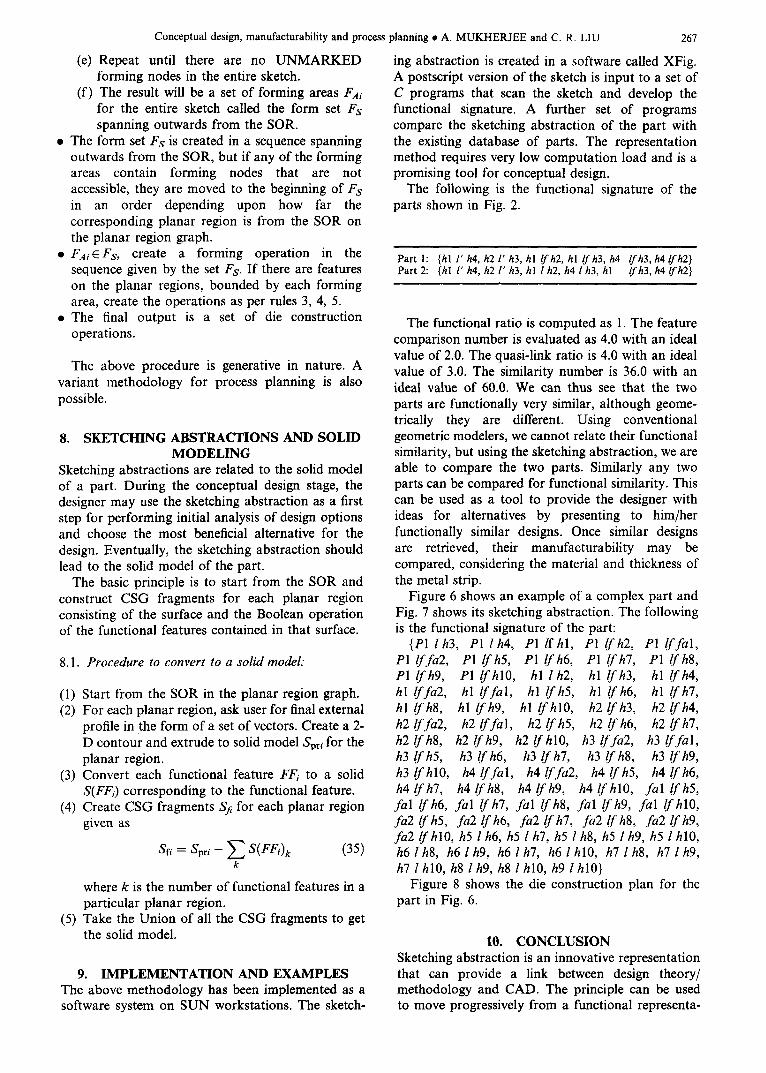
The following is the functional signature of the parts shown in Fig. 2.
Part !: {hi l ' h4, h2 l ' h3, hl /fh2, hl /fh3, h4 /fh3, h4/fh2} Part 2: {hl l' h4, h2 l' h3, hl l h2, h4 l h3, hl lfh3, h4/fh2}
The functional ratio is computed as 1. The feature comparison number is evaluated as 4.0 with an ideal value of 2.0. The quasi-link ratio is 4.0 with an ideal value of 3.0. The similarity number is 36.0 with an ideal value of 60.0. We can thus see that the two parts are functionally very similar, although geome- trically they are different. Using conventional geometric modelers, we cannot relate their functional similarity, but using the sketching abstraction, we are able to compare the two parts. Similarly any two parts can be compared for functional similarity. This can be used as a tool to provide the designer with ideas for alternatives by presenting to him/her functionally similar designs. Once similar designs are retrieved, their manufacturability may be compared, considering the material and thickness of the metal strip.
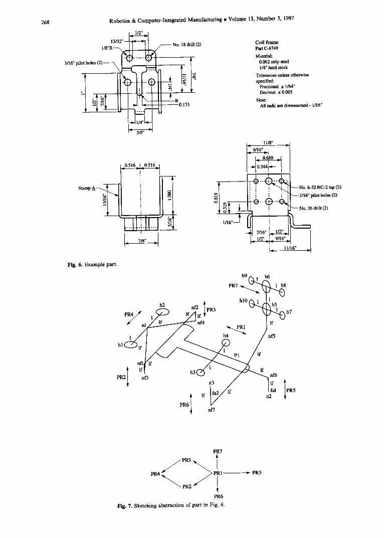
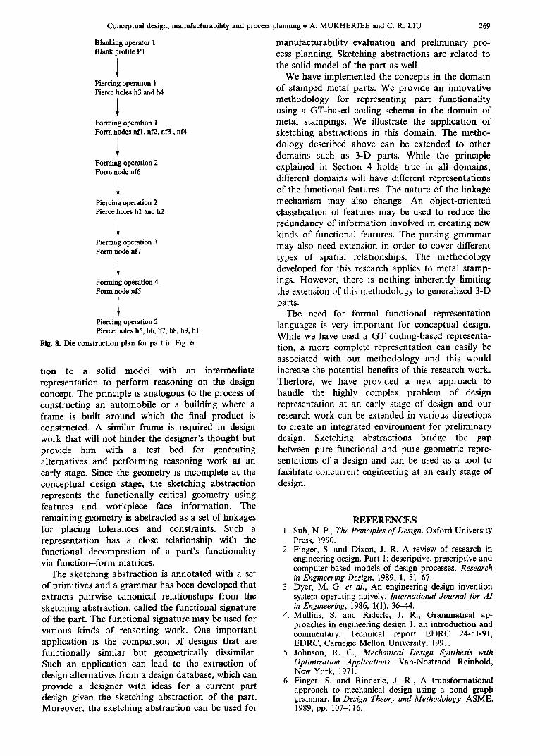
Figure 6 shows an example of a complex part and Fig. 7 shows its sketching abstraction. The following is the functional signature of the part:
{P1 l h3, P1 l h4, P1 / fh l , P1 lf h2, PI lf fal, P1 lf fa2, P1 lf h5, P1 lf h6, P1 lf h7, P1 lf h8, P1 /fh9, P1 /fhl0, hl l h2, hl lfh3, hl lfh4, hl lf fa2, hl If fal, hl lf h5, hl lf h6, hi lf h7, h l l fh8 , h l l fh9 , hl /fhl0, h2lfh3, h2lfh4, h2 lf fa2, h2 lf fal, h2 lf h5, h2 lf h6, h2 lf h7, h2/fh8, h2/fh9, h2 / fh l0 , h3 lffa2, h3 lffal, h3 lf h5, h3 lf h6, h3 lf h7, h3 lf h8, h3 lf h9, h3/ fh l0 , h4 lf fal, h4 lf fa2, h4 lf h5, h4 lf h6, h4 If h7, h4 lfh8, h4 lfh9, h4/ fhl0 , fal lfh5, fal lf h6, fal lf h7, fal lf h8, fal lf h9, fal /fhl0, fa2 lf h5, fa2 lf h6, fa2 /f h7, fa2 lf h8, fa2 lf h9, fa2 /f hl0, h5 l h6, h5 l h7, h5 l h8, h5 l h9, h5 l hlO, h61h8, h61h9, h61h7, h6 lh l0 , h71h8, h71h9, h7 l hl0, h8 lh9, h8 l hl0, h9 lhl0}
Figure 8 shows the die construction plan for the part in Fig. 6.
10. CONCLUSION Sketching abstraction is an innovative representation that can provide a link between design theory/ methodology and CAD. The principle can be used to move progressively from a functional representa-
268 Robotics & Computer-Integrated Manufacturing • Volume 13, Number 3, 1997
13/32" ' ~ l18"R~ /
3/16" pilot holes (2)
¢
Stamp A _ ~
1 0.516_1 _0.516_1 - r i- -I
' 1! I
I [
i i
l---l-[-i-l-l---I ~ I
718"
No. 18 drill (2) Coil frame Part (2-8749 Material:
IN 0.062 strip steel I~ 1/4" hard stock
Tolerances unless otherwise specified:
Fractional ± 1/64" Decimal ± 0.005
R Note: 0.173 All radii not dimensioned - 1/16"
11/8"
. ~ .g~o..¢:~_. I I f T ~ .--No. 6.32 Nc.2 tap (2)
1 J q ~
i I i ~ 3/16" pilot holes (2)
~-f---i-,,-O-~--~,
_~ 7,,6,,, ,,~,, I I_ 11116" _
Fig. 6. Example part.
P•nl ~l~,f
PR~ I
h9 (-~ 1 .h6 PR7 ~ . . . . ~ ~ 8
. hl0 ('~ 1 1
n f'2 I PR3 ~ ~51 - h7
/ I - - - 7 ~ nf4 PR1 If
/ / h4 ~ ' ~ / / R e 5
lffl If h 3 ~ ~ n f 6
nf3 n3 / I lf
l If I f ~ / ~ f 2fal IPR5
gs6~ n~7
PR7
S l
PR6 Fig. 7. Sketching abstraction of part in Fig. 6.
--- PR5
Conceptual design, manufacturability and process planning • A. MUKHERJEE and C. R. LIU
Blanking operator 1 Blank profile PI
Piercing operation 1 Pierce holes h3 and h4
Forming operation 1 Form nodes nfl, nf2, nf3, nf4
Fortmng operation 2 Form node nf6
Piercing operation 2 Pierce holes hl and h2
Piercing operation 3 Form node nf7
Forming operation 4 Form node nf5
Piercing operation 2 Pierce holes h5, h6, !!7, h8, hg, hl
Fig. 8. Die construction plan for part in Fig. 6.
tion to a solid model with an intermediate representation to perform reasoning on the design concept. The principle is analogous to the process of constructing an automobile or a building where a frame is built around which the final product is constructed. A similar frame is required in design work that will not hinder the designer's thought but provide him with a test bed for generating alternatives and performing reasoning work at an early stage. Since the geometry is incomplete at the conceptual design stage, the sketching abstraction represents the functionally critical geometry using features and workpiece face information. The remaining geometry is abstracted as a set of linkages for placing tolerances and constraints. Such a representation has a close relationship with the functional decompostion of a part's functionality via function-form matrices.
The sketching abstraction is annotated with a set of primitives and a grammar has been developed that extracts pairwise canonical relationships from the sketching abstraction, called the functional signature of the part. The functional signature may be used for various kinds of reasoning work. One important application is the comparison of designs that are functionally similar but geometrically dissimilar. Such an application can lead to the extraction of design alternatives from a design database, which can provide a designer with ideas for a current part design given the sketching abstraction of the part. Moreover, the sketching abstraction can be used for
269
manufacturability evaluation and preliminary pro- cess planning. Sketching abstractions are related to the solid model of the part as well.
We have implemented the concepts in the domain of stamped metal parts. We provide an innovative methodology for representing part functionality using a GT-based coding schema in the domain of metal stampings. We illustrate the application of sketching abstractions in this domain. The metho- dology described above can be extended to other domains such as 3-D parts. While the principle explained in Section 4 holds true in all domains, different domains will have different representations of the functional features. The nature of the linkage mechanism may also change. An object-oriented classification of features may be used to reduce the redundancy of information involved in creating new kinds of functional features. The parsing grammar may also need extension in order to cover different types of spatial relationships. The methodology developed for this research applies to metal stamp- ings. However, there is nothing inherently limiting the extension of this methodology to generalized 3-D parts.
The need for formal functional representation languages is very important for conceptual design. While we have used a GT coding-based representa- tion, a more complete representation can easily be associated with our methodology and this would increase the potential benefits of this research work. Therfore, we have provided a new approach to handle the highly complex problem of design representation at an early stage of design and our research work can be extended in various directions to create an integrated environment for preliminary design. Sketching abstractions bridge the gap between pure functional and pure geometric repre- sentations of a design and can be used as a tool to facilitate concurrent engineering at an early stage of design.
REFERENCES 1. Suh, N. P., The Principles of Design. Oxford University
Press, 1990. 2. Finger, S. and Dixon, J. R. A review of research in
engineering design. Part 1: descriptive, prescriptive and computer-based models of design processes. Research in Engineering Design, 1989, 1, 51-67.
3. Dyer, M. G. et al., An engineering design invention system operating naively. International Journal for A1 in Engineering, 1986, 1(1), 36~4.
4. Mullins, S. and Riderle, J. R., Grammatical ap- proaches in engineering design 1: an introduction and commentary. Technical report EDRC 24-51-91, EDRC, Carnegie Mellon University, 1991.
5. Johnson, R. C., Mechanical Design Synthesis with Optimization Applications. Van-Nostrand Reinhold, New York, 1971.
6. Finger, S. and Rinderle, J. R., A transformational approach to mechanical design using a bond graph grammar. In Design Theory and Methodology. ASME, 1989, pp. 107-116.
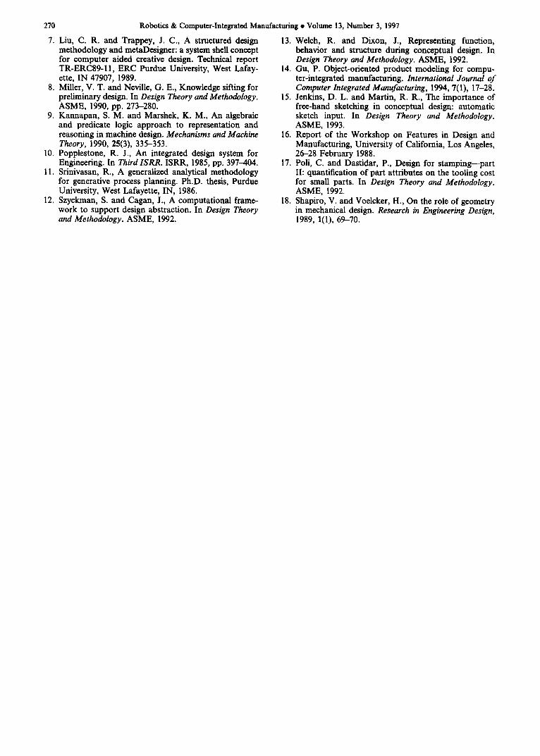
270 Robotics & Computer-Integrated Manufacturing • Volume 13, Number 3, 1997
7. Liu, C. R. and Trappey, J. C., A structured design 13. Welch, R. and Dixon, J., methodology and metaDesigner: a system shell concept for computer aided creative design. Technical report TR-ERC89-11, ERC Purdue University, West Lafay- ette, IN 47907, 1989.
8. Miller, V. T. and Neville, G. E., Knowledge sifting for preliminary design. In Design Theory and Methodology. ASME, 1990, pp. 273-280.
9. Kannapan, S. M. and Marshek, K. M., An algebraic and predicate logic approach to representation and reasoning in machine design. Mechanisms and Machine Theory, 1990, 25(3), 335-353.
10. Popplestone, R. J., An integrated design system for Engineering. In Third ISRR. ISRR, 1985, pp. 397--404.
11. Srinivasan, R., A generalized analytical methodology for generative process planning. Ph.D. thesis, Purdue University, West Lafayette, IN, 1986.
12. Szyckman, S. and Cagan, J., A computational frame- work to support design abstraction. In Design Theory and Methodology. ASME, 1992.
Representing function, behavior and structure during conceptual design. In Design Theory and Methodology. ASME, 1992.
14. Gu, P. Object-oriented product modeling for compu- ter-integrated manufacturing. International Journal of Computer Integrated Manufacturing, 1994, 7(1), 17-28.
15. Jenkins, D. L. and Martin, R. R., The importance of free-hand sketching in conceptual design: automatic sketch input. In Design Theory and Methodology. ASME, 1993.
16. Report of the Workshop on Features in Design and Manufacturing, University of California, Los Angeles, 26-28 February 1988.
17. Poll, C. and Dastidar, P., Design for stamping--part II: quantification of part attributes on the tooling cost for small parts. In Design Theory and Methodology. ASME, 1992.
18. Shapiro, V. and Voelcker, H., On the role of geometry in mechanical design. Research in Engineering Design, 1989, 1(1), 69-70.