Micro-stamped surfaces for the patterned growth of neural stem cells
9
Micro-stamped surfaces for the patterned growth of neural stem cells Ana Ruiz a , Leonora Buzanska a, b , Douglas Gilliland a , Hubert Rauscher a , Lucel Sirghi a , Tomasz Sobanski a , Marzena Zychowicz b , Laura Ceriotti a , Frederic Bretagnol a , Sandra Coecke a , Pascal Colpo a, * , François Rossi a a European Commission, Joint Research Centre, Institute for Health and Consumer Protection, TP 203. Via Fermi, 21027 Ispra (VA), Italy b Medical Research Clinical Institute, Polish Academy of Sciences, 5 Pawinskiego Street, 02-106 Warsaw, Poland article info Article history: Received 19 June 2008 Accepted 20 August 2008 Available online 25 September 2008 Keywords: Micropatterning Surface modification Peptide Adhesion molecule Cell adhesion Stem cell abstract We present a method for patterning neural stem cells based on pre-patterning polypeptides on a cell- repellent surface (poly(ethylene) oxide-like, PEO-like, plasma-deposited films). The method ensures cell attachment and stability for several weeks, as well as it allows cell migration and differentiation. Various patterns of w1 nm thick cell adhesive poly-L-lysine (PLL) have been created on a cell-repellent PEO-like matrix by microcontact printing using different array configurations and printing conditions. The cell-repellent property of PEO-like film determined the confinement of the cells on the printed patterns. Optimization of the printing method showed that the most homogeneous patterns over large areas were obtained using PLL diluted in carbonate buffer (100 mM) at pH 8.4. Neural stem cells cultured on the PLL patterns in low serum and in differentiating medium over 20 days exhibited a good confinement to the polypeptide domains. The number of cells attached increased linearly with the micro-stamped PLL area. The cells were able to extend random axon-like projections to the outside of the patterns and presented high amount of ramifications when cultured in differentiating medium. Migration and axon-like outgrowth have been successfully guided by means of an interconnected squares configuration. The surfaces are suitable for controlling the patterning of stem cells and provide a platform for the assess- ment of the way how different cell arrangements and culture conditions influence cell interactions and cell developmental processes. Ó 2008 Elsevier Ltd. All rights reserved. 1. Introduction In recent years there has been great interest in developing methods for exploiting the huge potential of stem cells in therapeutic and regenerative medicine. While great progress has been made, much still needs to be understood before the extremely complex biological system of stem cells can be effectively controlled and utilized. Recent advances in biotechnology are striving to provide the fundamental tools necessary to achieve this goal by developing advanced cell growth platforms. Through careful control of their physico-chemical properties, such platforms can provide an insight into how surfaces with different chemistries and culture conditions can affect cell interactions and cell developmental processes [1–3]. Amongst the many physico-chemical properties that may be controlled and that can greatly influence cell growth behaviour is the spatial distribution of adhesion molecules and extracellular matrix proteins on surfaces [4–8]. For instance, micropatterned substrates have been used successfully to guide cell migration of fibroblasts [9], to control growth, apoptosis and differentiation of capillary endo- thelial cells [10,11], and to study spreading of melanoma mouse cells [12]. Among the techniques available for protein patterning of surfaces, microcontact printing [13–15] achieves a good balance between simplicity, low cost, reproducibility, compatibility and high filling efficiency of the treated surface [16,17]. This technique has been successfully applied in producing patterns with highly con- trasted chemicalfunctionalities [18,19] and to pattern proteins for the study of bio–non bio interactions and for cell attachment [20–24]. Many type of cells attach firmly on surfaces to which polylysine has been adsorbed. The polycationic poly-L-lysine molecules adsorb strongly to various solid surfaces, presenting cationic sites where the anionic sites on cell surfaces may bind. Over the years, uniform poly-L-lysine coatings have been used to favor the attachment and spreading of cells for observation purposes [25]. The use of uniform layers, however, yields to surfaces with high packing density of cells in which the observation of cell migration and development is difficult to follow, especially in the case of stem cells, which can evolve in multiple directions and form heterogeneous populations of cells in different fates. Patterning of adhesion molecules in arranged arrays may confine the number of cells on the fabricated surfaces in spots that are easily tracked. * Corresponding author. Fax: þ39 0332 78 5787. E-mail address: [email protected] (P. Colpo). Contents lists available at ScienceDirect Biomaterials journal homepage: www.elsevier.com/locate/biomaterials 0142-9612/$ – see front matter Ó 2008 Elsevier Ltd. All rights reserved. doi:10.1016/j.biomaterials.2008.08.017 Biomaterials 29 (2008) 4766–4774
-
Upload
independent -
Category
Documents
-
view
0 -
download
0
Transcript of Micro-stamped surfaces for the patterned growth of neural stem cells

Micro-stamped surfaces for the patterned growth of neural stem cells
Ana Ruiz a, Leonora Buzanska a,b, Douglas Gilliland a, Hubert Rauscher a, Lucel Sirghi a,Tomasz Sobanski a, Marzena Zychowicz b, Laura Ceriotti a, Frederic Bretagnol a,Sandra Coecke a, Pascal Colpo a,*, François Rossi a
a European Commission, Joint Research Centre, Institute for Health and Consumer Protection, TP 203. Via Fermi, 21027 Ispra (VA), Italyb Medical Research Clinical Institute, Polish Academy of Sciences, 5 Pawinskiego Street, 02-106 Warsaw, Poland
a r t i c l e i n f o
Article history:Received 19 June 2008Accepted 20 August 2008Available online 25 September 2008
Keywords:MicropatterningSurface modificationPeptideAdhesion moleculeCell adhesionStem cell
a b s t r a c t
We present a method for patterning neural stem cells based on pre-patterning polypeptides on a cell-repellent surface (poly(ethylene) oxide-like, PEO-like, plasma-deposited films). The method ensures cellattachment and stability for several weeks, as well as it allows cell migration and differentiation. Variouspatterns of w1 nm thick cell adhesive poly-L-lysine (PLL) have been created on a cell-repellent PEO-likematrix by microcontact printing using different array configurations and printing conditions. Thecell-repellent property of PEO-like film determined the confinement of the cells on the printed patterns.Optimization of the printing method showed that the most homogeneous patterns over large areas wereobtained using PLL diluted in carbonate buffer (100 mM) at pH 8.4. Neural stem cells cultured on the PLLpatterns in low serum and in differentiating medium over 20 days exhibited a good confinement to thepolypeptide domains. The number of cells attached increased linearly with the micro-stamped PLL area.The cells were able to extend random axon-like projections to the outside of the patterns and presentedhigh amount of ramifications when cultured in differentiating medium. Migration and axon-likeoutgrowth have been successfully guided by means of an interconnected squares configuration. Thesurfaces are suitable for controlling the patterning of stem cells and provide a platform for the assess-ment of the way how different cell arrangements and culture conditions influence cell interactions andcell developmental processes.
! 2008 Elsevier Ltd. All rights reserved.
1. Introduction
In recent years there has been great interest in developingmethods for exploiting the huge potential of stem cells in therapeuticand regenerative medicine. While great progress has been made,much still needs to be understood before the extremely complexbiological system of stem cells can be effectively controlled andutilized. Recent advances in biotechnology are striving to provide thefundamental tools necessary to achieve this goal by developingadvanced cell growth platforms. Through careful control of theirphysico-chemical properties, such platforms can provide an insightinto how surfaces with different chemistries and culture conditionscan affect cell interactions and cell developmental processes [1–3].Amongst the many physico-chemical properties that may becontrolled and that can greatly influence cell growth behaviour is thespatial distribution of adhesion molecules and extracellular matrixproteins on surfaces [4–8]. For instance, micropatterned substrateshave been used successfully to guide cell migration of fibroblasts [9],
to control growth, apoptosis and differentiation of capillary endo-thelial cells [10,11], and to study spreading of melanoma mouse cells[12]. Among the techniques available for protein patterning ofsurfaces, microcontact printing [13–15] achieves a good balancebetween simplicity, low cost, reproducibility, compatibility and highfilling efficiency of the treated surface [16,17]. This technique hasbeen successfully applied in producing patterns with highly con-trasted chemical functionalities [18,19] and to patternproteins for thestudy of bio–non bio interactions and for cell attachment [20–24].
Many type of cells attach firmly on surfaces to which polylysinehas been adsorbed. The polycationic poly-L-lysine molecules adsorbstrongly to various solid surfaces, presenting cationic sites wherethe anionic sites on cell surfaces may bind. Over the years, uniformpoly-L-lysine coatings have been used to favor the attachment andspreading of cells for observation purposes [25]. The use of uniformlayers, however, yields to surfaces with high packing density of cellsin which the observation of cell migration and development isdifficult to follow, especially in the case of stem cells, which canevolve in multiple directions and form heterogeneous populationsof cells in different fates. Patterning of adhesion molecules inarranged arrays may confine the number of cells on the fabricatedsurfaces in spots that are easily tracked.
* Corresponding author. Fax: !39 0332 78 5787.E-mail address: [email protected] (P. Colpo).
Contents lists available at ScienceDirect
Biomaterials
journal homepage: www.elsevier .com/locate/biomater ia ls
0142-9612/$ – see front matter ! 2008 Elsevier Ltd. All rights reserved.doi:10.1016/j.biomaterials.2008.08.017
Biomaterials 29 (2008) 4766–4774

In this framework, we have developed and optimized a platformfor patterning of human umbilical cord blood – derived neural stemcells in order to study their activity when interacting with poly-peptide micropatterns on a biologically non-adhesive surface. Toproduce these surfaces, microcontact printing has been used todeposit geometrically controlled patterns of poly-L-lysine (PLL) onsubstrates previously coated with a protein-resistant and cell-repellent poly(ethylene) oxide-like film, (PEO-like). The PEO-likelayer, produced by plasma polymerization [26], has the importantcharacteristic of being cell repellent in solution but protein adhesiveunder the dry conditions used during the microcontact printingoperation [27,28]. The PLL transferred to the substrate in theseconditions was stable for more than four weeks [28], as it has beenrevealed by fluorescence imaging of the samples after immersion inwater for one month. In this way, it has been possible to controllablyproduce localized cell attachment with long-term stability. Prelimi-nary studies on proliferation, migration and differentiation mecha-nisms have been performed on surfaces having different polypeptideconfigurations. It is envisioned that this technique may find appli-cations in studying many different aspects of stem cells behaviour aswell as being readily adaptable to use with other types of cells.
2. Methods
2.1. Poly(ethylene) oxide deposition
PEO-like films have been deposited by plasma-enhanced chemical vapordeposition in a capacitively coupled reactor, using a glow discharge in diethyleneglycol dimethyl ether vapor (Sigma Aldrich) as described previously [29].
2.2. Fabrication of micropatterned surfaces
Moulds for the microcontact printing process were fabricated by casting poly-dimethylsiloxane (PDMS) silicone elastomer against a silicon master. The PDMS(Sylgard 184) was used in 10:1 mixture of base elastomer-curing agent and hardenedat 65 "C for 4 h. The silicon masters were fabricated by photolithography and reactiveion etching. The patterns were generated by photolithography on a photoresist(Shipley S1813) deposited on silicon substrate by spin coating (2000 rpm, 1 min).Following the resist development, the patterns were transferred to the silicon byreactive ion etching in a SF6 inductively coupled plasma (10 mtorr, 400 W, #60 Vbias). Then, the photoresist mask was removed by ultrasonication in acetone and thestructured silicon was coated with a low adhesion teflon-like layer (CFx) deposited byplasma polymerization from C4F8 gas (50 mtorr,#40 V bias). The presence of the lowadhesion teflon-like layer was crucial to achieving a good, undamaged replica of themicrostructures by facilitating the PDMS peel off. Then, the microstructured PDMSwere used as stamps for the direct printing of the poly-L-lysine on Petri dishes coatedwith a plasma polymerized polyethylene oxide-like film.
Poly-L-lysine FITC-labelled (PLL) 25 mg/ml at different pH (6–10) and bufferconcentration (20 mM, 100 mM) was used as inking solution. Before inking, the PDMSstamps were ultrasonicated in ethanol for 5 min and cleaned in mild O2 plasma(200 W, 1.2 mtorr) for 30 s in order to increase the hydrophilic character of the PDMSby forming more silica groups on the surface [30]. The hydrophilic PDMS stampswere then inked at room temperature with the PLL solution for 15 min after whichthe polypeptide solution was removed and the stamps were dried in a N2 stream.The inked stamps were put in contact with the substrates for 5 min. Before seedingthe cells, the PLL patterned surfaces were sterilised by UV for 15 min.
2.3. Characterisation
To study the optimal conditions for the protein transfer from the PDMS stamp tothe PEO-like surface we performed atomic force microscopy (AFM) measurements ofthe adhesive force between PEO-like covered AFM probes (NSG 11 from NT-MDT)and PLL-coated PDMS surfaces. The radius of the tip of the AFM probe was measuredby scanning a silicon grating with well-defined and very sharp topography features(TGG1 from NT-MDT). The radius of the AFM tip was about 7 nm before PEO-likedeposition and 24 nm after PEO-like deposition. The PEO-like film was deposited onthe AFM probes by the same method as that described for the PEO-like coating ofPetri dishes. The adhesive force was determined as the value of the AFM tipdetachment force observed on retract force–displacement curves (see the typicalforce curve plots in Supplementary Fig. 1) acquired on arrays of 10$10 pointshomogeneously distributed on an area of 1 mm$ 1 mm of the sample surface.
Ellipsometric data were acquired with a variable angle imaging ellipsometer(model EP3 by Nanofilm Surface Analysis GmbH, Germany). All imaging measure-ments were performed in air at room temperature at an angle of incidence of 42" ,using a monochromatized high power Xe lamp at a wavelength of l% 554.3 nm.
A polarizer–compensator–sample-analyzer (PCSA) null-ellipsometric procedurewas used to obtain maps of the D and J angles for the selected area. Thickness mapswere calculated from the D and J maps by point-by-point modeling with theellipsometer software EP3View using a two-layer model comprising the PEO-likeand stamped PLL layers. The thickness (11.9 nm) and the refractive index of plasma-deposited PEO-like (nPEO% 1.52) were independently determined by an angle-resolved measurement. A refractive index of 1.46 was used for PLL [31].
The deposited films were characterised with surface plasmon resonanceimaging (SPRi) (Genoptics, France) equipment. Changes in the refractive indexbetween gold and the dielectric substrate were measured using a collimated LEDwith a centre wavelength of 810 nm. The working angle was determined in phos-phate buffer saline as the maximum of the first derivative of the plasmonic curvetaken from q% 53" to q% 63" and the reflectance measured was used as reference.Fibronectin (Fn) binding was monitored as reflectivity shift with respect to the PBSreference.
TOF-SIMS analysis was conducted using an ION-TOF (IV) TOF-SIMS systemequipped with a 25 keV cluster metal ion source operating with Bi3! primary ions.Spectral analyses were obtained from square areas of 250$ 250 mm2 in high massresolution burst mode (resolution M/DM> 6000). Chemical imaging was done onareas of 500 mm$ 500 mm with raster resolution of 256$ 256 analysis points. In allcases, the total ion beam dose was limited to less than 1$1012 ions cm#2 and thuswas within the static SIMS regime.
Fluorescent imaging of proteins, optical imaging of the cells and time-lapsemeasurements were carried out by a Zeiss inverted microscope Axiovert 200equipped with an incubator.
2.4. Cell culturing
Neural stem cell line obtained from non-hematopoietic mononuclear fraction ofhuman umbilical cord blood (HUCB-NSC) [32] was maintained as the mixedadherent/floating culture in Dulbecco’s modified Eagle medium (DMEM/F12, Gibco)containing 2% fetal bovine serum (FBS, Gibco), insulin–transferrin–selenium(ITS,1:100, Gibco), antibiotic–antimycotic solution AAS (1:100, Gibco), at 37 "C, 5%CO2, and 95% humidity. HUCB-NSC cultures were propagated every two weeks bytrypsinization (Trypsin/EDTA 0,0 25%, Gibco) in 1:4 ratio. For the growth onpatterned surfaces, the cells were plated either at low (104 cells cm#2) or high(>5$104 cells cm#2) densities. Following overnight adhesion the cells whichremained non-attached were washed out with culture medium before control ordifferentiating (100 mM dBcAMP, Sigma) conditions were applied. During eachexperiment the control and differentiating medium were changed every two days.
2.5. Immunostaining
HUCB-NSC were fixed for 15 min in 4% paraformaldehyde/PBS. After fixation, thecells were permeabilized in PBS solution of 1% Triton$ 100 for 15 min. Blockingsolution, containing 10% normal goat serum in PBS, was applied for 1 h at roomtemperature. The cells were then incubated overnight at 4 "C with primary anti-bodies: monoclonal IgG2a anti b-tubulinIII (1:1000, Sigma) and polyclonal S100b(Swant) and further detected for 2 h at room temperature by secondary goat antimouse IgG2a Alexa 488 and goat anti rabbit IgG H! L Alexa 546 (Molecular Probes),respectively. To visualise the nuclei, cultures were incubated with Hoechst 33342(1:1000, Molecular Probes) for 20 min. For statistical evaluation of differencesbetween the number of cells attached at different culture conditions, ANOVA testwas used (Graph Pad Prism 4.1, GraphPad Software, San Diego, CA).
3. Results
3.1. PLL micropatterning
Surfaces with cell adhesive/non-adhesive contrast have beenproduced by depositing PLL on PEO-like films in dried conditionsusing the microcontact printing technique. The quality of the PLLpatterning has been optimized by using different polypeptidesolutions, namely PLL diluted at pH from 6 to 10 in carbonate bufferat different concentrations. Low aspect ratio PDMS stamps havebeen used for this study (w/l% 1/160, with w being the height of thestructures and l the distance between structures). Collapsing of thepatterns was observed when buffer concentration was 20 mM,whereas higher buffer concentration (100 mM) allowed producingwell-defined patterns. The quality of the PLL patterns dependedalso on the pH of the polypeptide solution. At pH 7 generally goodpatterns could be obtained for carbonate buffer 100 mM, but forsome printing experiments that used these conditions the stampscollapsed in some part of the sample. For pH above 8 generally goodpatterns were obtained, while for pH values close to the PLL
A. Ruiz et al. / Biomaterials 29 (2008) 4766–4774 4767
isoelectric point (which is 9.7) the printing produced inhomoge-neous coating areas evidencing a low efficiency of PLL transfer fromthe PDMS stamps to the substrate. These results are explainedby our AFM investigation of the adhesive force between PLL andPEO-like, force that determines the effectiveness of PLL transferfrom the PDMS stamp to the PEO-like film surface. Fig. 1 shows thehistograms of the adhesive force between the PEO-like coated AFMprobe and PLL adsorbed to PDMS at different values of pH andbuffer concentration obtained at 30% relative humidity (RH). Themeasurements show that the adhesive force increases by thedecrease of either the pH or the salt concentration. The adhesiveforce was dependent on air RH (Supplementary Fig. 1), whichindicates that it was created mainly by the capillary water meniscus
formed at tip-sample contact [33]. Patterns printed at low pH andsalt concentration may collapse due to the strong adhesion forcebetween the inked stamp and PEO-like surface. On the other hand,low quality patterns are fabricated at high pH and salt concentra-tion due to the weak adhesive force, which is the cause of a low PLLtransfer efficiency. Therefore, these measurements show thatoptimal conditions for microcontact printing of PLL patterns are inintermediate values of pH and salt concentration.
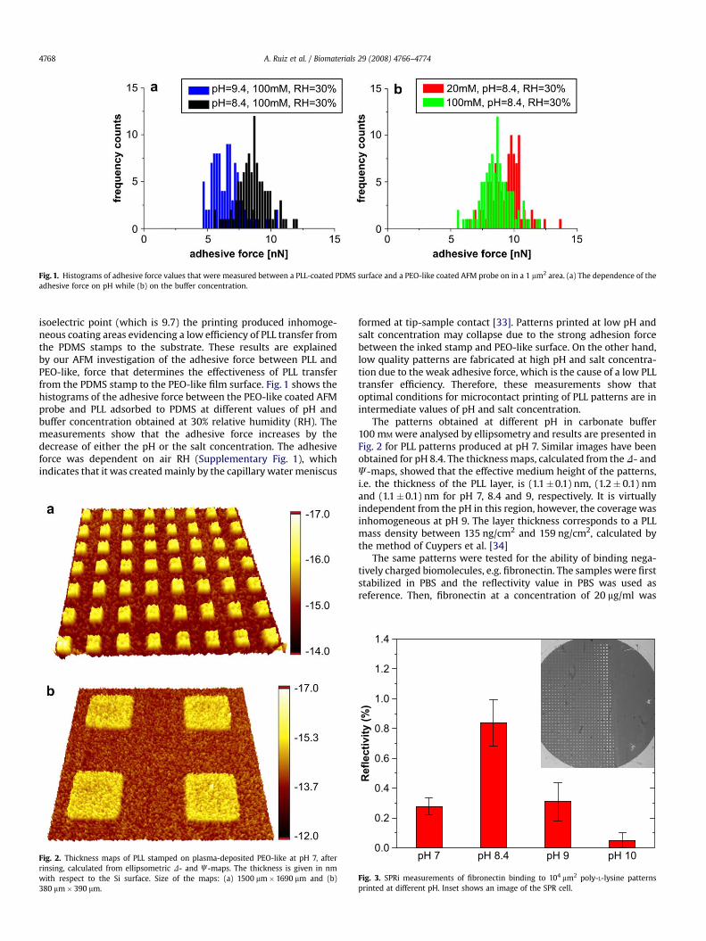
The patterns obtained at different pH in carbonate buffer100 mM were analysed by ellipsometry and results are presented inFig. 2 for PLL patterns produced at pH 7. Similar images have beenobtained for pH 8.4. The thickness maps, calculated from the D- andJ-maps, showed that the effective medium height of the patterns,i.e. the thickness of the PLL layer, is (1.1&0.1) nm, (1.2& 0.1) nmand (1.1&0.1) nm for pH 7, 8.4 and 9, respectively. It is virtuallyindependent from the pH in this region, however, the coverage wasinhomogeneous at pH 9. The layer thickness corresponds to a PLLmass density between 135 ng/cm2 and 159 ng/cm2, calculated bythe method of Cuypers et al. [34]
The same patterns were tested for the ability of binding nega-tively charged biomolecules, e.g. fibronectin. The samples were firststabilized in PBS and the reflectivity value in PBS was used asreference. Then, fibronectin at a concentration of 20 mg/ml was
Fig. 1. Histograms of adhesive force values that were measured between a PLL-coated PDMS surface and a PEO-like coated AFM probe on in a 1 mm2 area. (a) The dependence of theadhesive force on pH while (b) on the buffer concentration.
Fig. 2. Thickness maps of PLL stamped on plasma-deposited PEO-like at pH 7, afterrinsing, calculated from ellipsometric D- and J-maps. The thickness is given in nmwith respect to the Si surface. Size of the maps: (a) 1500 mm$ 1690 mm and (b)380 mm$ 390 mm.
0.0
0.2
0.4
0.6
0.8
1.0
1.2
1.4
pH 10pH 9pH 8.4
Re
fle
ctiv
ity
(%
)
pH 7
Fig. 3. SPRi measurements of fibronectin binding to 104 mm2 poly-L-lysine patternsprinted at different pH. Inset shows an image of the SPR cell.
A. Ruiz et al. / Biomaterials 29 (2008) 4766–47744768

injected, followed by a washing step. After washing, the change inreflectivity was measured in 10 locations over the patterns andaveraged. The SPRi results are presented in Fig. 3, showing that thelargest Fn binding was obtained at pH 8.4. Fig. 4 shows the fluo-rescence images (a–c) and density images of positive ion species(d–f) corresponding to PEO-like background (C3H3O!) and PLLcovered pattern (CN!) as measured by ToF-SIMS.
3.2. Cell culturing
HUCB-NSC [32] were incubated in high density conditions(>5$104 cells cm#2) on patterns created from solutions at pH from6 to 10. Fig. 5a shows the plots of the number of cells attached to104 mm2 PLL patterns as a function of the pH. For cell counting, thecells were fixed after one day of incubation and the nuclei werestained with Hoechst. The mean value of the number of cells
attached to the squares was similar in all cases (w28 cells), but thestandard deviation was higher for pH 6 and pH 9. At pH 10 we didnot observe any cell pattern. PLL patterns consisting in arrays ofsquares with 100 mm2 to 5.7$104 mm2 area were printed using PLLsolutions at pH 8.4 in 100 mM carbonate buffer, which had thelowest standard deviation in the number of cells attached. Fig. 5bplots the number of cells attached to the PLL patches versus the PLLprinted area, showing a linear increase of the number of cells withthe size of the PLL stamped patches. Different layouts of PLLpatterns were printed using the same conditions in order to studydifferent aspects of cell behaviour. Fig. 6 shows images of HUCB-NSC cultured at high (a–c) and low (d–f) cell density on PLL patternswith sizes of 2.7$104 mm2 and 104 mm2, respectively, which wereused to study cell–cell interactions inside and between patches.Fig. 7 shows an example of cell migration in 104 mm2 isolatedsquares, while Fig. 8 demonstrates the guided cell migration and
Fig. 4. Fluorescence microscopy images of the PLL patterns. Long inter-patch distances (a) are suited to study stem cell maintenance and long migration while close islands (b) andislands connected by lines (c) are used for monitoring short migrations and outgrowth projections. ToF-SIMS mapping showed good chemical contrast between PLL positive areas(d, f) recognized by C–N, and PEO-like positive background (e.g.) ascribed to C3–H3–O.
0
5
10
15
20
25
30
35
N° c
ell
s
pH
6 7 8 9 0 1 2 3 4 5 6-20
0
20
40
60
80
100
120
140
160
N° c
ell
s
PLL size (x104 µm
2)
ab
Fig. 5. Number of cells attached to 104 mm2 PLL squares printed using PLL solutions at different pH (a) and number of cells as a function of the PLL printed area in patterns created atpH 8.4 (b). High cell density plating conditions.
A. Ruiz et al. / Biomaterials 29 (2008) 4766–4774 4769

Fig. 6. HUCB-neural stem cells incubated on PLL patterns in high density conditions (a–c) and in low density (d–f) after one day of culture. Cells plated in high density crowded thePLL adhesive patches very compactly and kept the round shape, while low packed samples permitted the flattening of cells favouring the extension of random (arrow in e) or guided(f) cell projections.
Fig. 7. Sequences of pictures showing the processes of migration undergone on the patterns consisting of 104 mm2 PLL isolated squares. Cells (arrowed) migrate from one patchtowards the neighbour patch. High cell density plating conditions.
A. Ruiz et al. / Biomaterials 29 (2008) 4766–47744770

outgrowth of cell protrusions on patterns with line bridgesbetween the same squares. Fig. 9 shows the random and guidedoutgrowth of the cells on the same patterned configurations incontrol (neuromorphogene-free medium) and in differentiatingmedium. To demonstrate that HUCB-NSC growing on the PLLpatterns are committed to neural lineages, we investigatedexpression of b-tubulinIII and S100b proteins, typical for neuronaland astrocytic cells, respectively. In the pattern with inter-connecting lines, the cells cultured in control, neuromorphogene-free conditions (Fig. 9c) are committed to neuronal and astrocyticlineages, as can be seen by the presence of cells expressingb-tubulinIII (green) and S100b (red), though cells remain undiffer-entiated, lacking extended protrusions. The presence of dBcAMPdirects HUCB-NSC into neural cells, which can be seen from theguided growth of axon-like extensions along the interconnectinglines (Fig. 9d, arrowed).
4. Discussion
In this work, PLL has been patterned on an antifouling PEO-likesubstrate to facilitate the observation of cell behaviour. Non-specific adsorption of cells to PLL through anionic–cationic inter-actions allows both cell patterning and cell movement. Cellpatterning has been obtained as a result of cell confinement in thePLL spots achieved by the PEO-like antifouling characteristic, whichallows easy observation of cell behaviour. Since the cells are notanchored through integrin-mediated ligands, they are able to easily
migrate and spread. The change in morphology when the cells arespreading over the PLL areas promotes stem cell commitment anddifferentiation.
The pH and the buffer concentration were the most criticalparameters for the success of the patterning by microcontactprinting. Optimum results have been obtained by diluting the PLLin carbonate buffer (100 mM) at pH 8.4, as concluded from thesurface analyses. The polypeptide deposition on PDMS results ina positively charged surface. Collapsing of the patterns is due tostrong adhesive PLL–PEO interaction between the cationic PLLgroups and the anionic PEO-like termination. The AFM study of theadhesive force between PEO-like coated AFM probes and PLLdeposited on PDMS (Fig. 1) showed that the long-range electro-static force observed during the approach of the AFM tip to thesample surface increases by decreasing the pH and by decreasingthe buffer concentration. The electrostatic force can be cancelledout by increasing the air humidity level. The water vapor from thehumid air condenses on the electrically charged surface and shieldsthe electric charge responsible for the long-range attraction (seesupporting Fig. 1). Increased air humidity has also a strong effect onthe short range adhesive force. The water layers adsorbed on thesurfaces coalesce to form a water meniscus at the microscopiccontact which generates a strong adhesion force and we believethat it contributes to the transfer of material (protein) from onesurface to the other during microcontact printing.
The thickness of the polypeptide layer, measured by ellipsom-etry, depends only on the conformal contact, as similar w1 nm
Fig. 8. Sequences of pictures showing the processes of outgrowth and migration undergone on the patterns consisting of 104 mm2 PLL squares connected via 15 mm lines. (a) A cell(arrowed) extending projections to the left and the upper patch. (b) A cell (circled) travels from one patch to the bottom along the line bridge. Low cell density plating conditions.
A. Ruiz et al. / Biomaterials 29 (2008) 4766–4774 4771

thick PLL patterns were obtained on fully coated squares at pH 7–9.However, printing at pH 9 resulted in many hollow or partiallycoated squares, which is indicative of an incomplete PLL transferfrom PDMS to the PEO-like surface due to the weak adhesive forcegiven by the low positive charge of PLL at pH 9, close to itsisoelectric point (9.7). The sample printed at pH 8.4 presented thehighest amount of free cationic sites for protein binding, as indi-cated by the highest detected change in reflectivity (0.8%) duringSPRi measurements (Fig. 3). In this pattern, ToF-SIMS positive ionimaging of PLL (CN fragment, ascribed to C–N bonding, see Fig. 4dand f) clearly shows a large difference in intensity of this ionbetween the printed area and the surrounding PEO-like back-ground, demonstrating that the PLL is only delivered in the squareswhile the surrounding background is totally PLL free.
Cell arrays containing a different number of cells can beobtained by changing the PLL pattern dimensions (Fig. 5b). Fromthese results, we used 2.7$104 mm2 and 104 mm2 as PLL areas forfurther cell behaviour studies. The large squares (2.7$104 mm2)separated by long inter-patch distances (spaced 400 mm) hada significantly larger amount of cells per PLL patch (68& 4) than thesmaller squares (104 mm2) separated by shorter distances (100 mm)(29& 3). In these conditions both kind of patterns had suitableamount of cells attached to the patch for studying cell migrationand proliferation (Fig. 6a,b), however, only short distance pattern,either isolated or with interconnected lines, in low density platingconditions (Fig. 6e,f) are suitable for studying stem celldifferentiation.
Cells growing on different substrate geometries showed shapedifferences depending on the cell plating density (Fig. 6). In thestructures containing a high cell density (a–c), the cells are forced toretain a round morphology and are inhibited from spreading whilein structures with low density packing, the cells can change
morphology and spread following the shape of the patterns (d–f),which may influence stem cell commitment [35]. Cells on denselycrowded islands stayed in non-differentiated mode longer than lowpopulated samples where cell commitment to a differentiatedmode is favoured. By reducing the gap between the isolatedsquares, the cells are able to extend protrusions towards theneighbouring patch of cells (arrow in (e)). Such projections were setout randomly and in many cases the cells in one patch could notreach the neighbouring island. Monitoring of the cells for threedays showed that the stem cells were moving reluctantly on thenon-adhesive background and either retracted and moved back tothe ‘‘home’’ square (which was observed mainly when the cellswere spread on the square) or migrate to the next square (observedwhen the cells maintained a round shape and small projections)(Fig. 7).
The cells were also monitored for three days in the pattern of104 mm2 patches with interconnecting bridges (see SupplementaryVideo 1). Bridging connections between islands guided cell motionand the cell protrusion outgrowth. In this case, any movement ofthe cells takes place across the bridges provided. Differentsequences of pictures are extracted from the movie to highlight thedifferent types of cell movement and behaviour (Fig. 8). The cellsextended thin axon-like projections along the lines towards thenext square (a). These projections, in some cases, were found toretract after a period of time but often the extended projectionsremained stable and acquired axonal or dendritic-like features (asrevealed by b-tubulin III immunostaining, Fig. 9). Another type ofbehaviour was characteristic of small, poorly-attached cells whichdid not extend long projections but used the lines to migrate to thenext patch (Fig. 8b). It was also observed that when wide projec-tions are extended, the cell cytoplasm together with the cellnucleus is able to flow along the projection. In some cases, the cell
Fig. 9. HUCB-neural stem cells show long ramified axon-like projections when grown under neuromorphogene exposure in isolated squares (a), such projections are guided to theneighbour group of cells by patterning interconnections (b). Arrow in (b) indicates an axon-like projection reaching a cell located in the neighbour square. Immunostaining withb-tubulin III and S100b in control (c) and in differentiating conditions (d) confirmed the neuronal and astrocytic commitment.
A. Ruiz et al. / Biomaterials 29 (2008) 4766–47744772

nucleus moves towards the next square and then moves back, withthe cell finally coming to rest on its initial square (see Supple-mentary Video 1). Such a process of cell nucleus translocation(interkinetic nuclear migration) is typical for the neural stem cellsrepresented by radial glia in the developing human central nervoussystem [36]. The full, in-vitro, differentiation of HUCB-NSC intoneuron-like functional cells would be expected to take betweentwo and four weeks [37,38]. The time-lapse measurements pre-sented here cover only the initial 72 h in culture in control condi-tions (low serum), however, early stages of cell commitment toneuronal or astrocytic fate are present, as evidenced by immuno-cytochemistry (Fig. 9).
The patterned platforms have been also used to study the effectsof different culture medium conditions. In the presence of dBcAMP,the neural stem cells proliferated less and more readily extendedaxon-like protrusions. As shown in Fig. 9a, the body of the cells wasattached to the square pattern and extended projections outsidethe square. The dendritic/axonal projections were much moreramified than in the control, neuromorphogene-free culture. In thecase of the square adhesion patch the projections randomlyoutgrew in all directions while in the case of patterns with inter-connections (Fig. 9b) the outgrowth was guided along the inter-connect patches. In some cases, the longest axon-like projectionswere able to reach along the interconnect and contact a cell bodysituated in the next island (arrowed). Immunocytochemistry withb-tubulinIII confirmed the early stage of neuronal differentiation(Fig. 9d).
5. Conclusions
Micropatterns of cell adhesive areas in a non-adhesive back-ground have been produced by microcontact printing. Large areaswith uniform patterns of isolated and interconnected squaresconsisting of 1 nm thick poly-L-lysine on a poly(ethylene) oxide-like surface have been prepared using carbonate buffer 100 mM atpH 8.4 for the polypeptide inking solution. Tuning the electrostaticinteraction between the stamp and the surface allowed obtaininghigh quality patterns with low aspect ratio stamps (1/160 aspectratio PDMS structures). The contrasted adhesive/non-adhesiveareas created this way are stable for more than one month, and arecapable to confine, localize and guide growth of cells, which facil-itates the monitoring of different cell developmental processes andcell–cell interactions. Neural stem cells derived from human cordblood have been cultured on the PLL patterns and show goodadhesion and long-term confinement to the PLL areas. Monitoringof random and guided axonal outgrowth and migration has beenachieved by patterning the neural stem cells in tailored configu-rations. The surfaces have been proven to be suitable for theculturing of stem cells and exhibit patterned regions where it ispossible to easily monitor cell adhesion, movement, growth anddifferentiation.
Acknowledgements
This project has been financed by the European CommissionJoint Research Centre Actions ‘‘NanoBiotechnology for Health’’ and‘‘Validation for Consumer Products’’. The authors thank the tech-nical support received from Thierry Martin, Giovanni Maselli andSimone Malfara.
Appendix. Supplementary material
Supplementary material associated with this article can be found,in the online version, at doi:10.1016/j.biomaterials.2008.08.017.
References
[1] Falconnet D, Csucs G, Grandin HM, Textor M. Surface engineering approachesto micropattern surfaces for cell-based assays. Biomaterials 2006;27:3044–63.
[2] Fukuda J, Khademhosseini A, Yeh J, Eng G, Cheng J, Farokhzad OC, et al.Micropatterned cell co-cultures using layer-by-layer deposition of extracel-lular matrix components. Biomaterials 2006;27:1479–86.
[3] Fink J, Thery M, Azioune A, Dupont R, Chatelain F, Bornens M, et al.Comparative study and improvement of current cell micro-patterning tech-niques. Lab Chip 2007;7:672–80.
[4] Cavalcanti-Adam EA, Volberg T, Micoulet A, Kessler H, Geiger B, Spatz JP. Cellspreading and focal adhesion dynamics are regulated by spacing of integrinligands. Biophys J 2007;92:2964–74.
[5] Dang JM, Leong KW. Myogenic induction of aligned mesenchymal stem cellsheets by culture on thermally responsive electrospun nanofibers. Adv Mater2007;19:2775–9.
[6] Park SY, Park SY, Namgung S, Kim B, Im J, Kim JY, et al. Carbon nanotubemonolayer patterns for directed growth of mesenchymal stem cells. AdvMater 2007;19:2530–4.
[7] Karp JM, Yeh J, Eng G, Fukuda J, Blumling J, Suh KY, et al. Controlling size,shape and homogeneity of embryoid bodies using poly(ethylene glycol)microwells. Lab Chip 2007;7:786–94.
[8] Weibel DB, DiLuzio WR, Whitesides GM. Microfabrication meets microbiology.Nature 2007;210:209–18.
[9] Kumar G, Ho CC, Co CC. Guiding cell migration using one-way micropatternarrays. Adv Mater 2007;19:1084–90.
[10] Chen CS, Mrksich M, Huan S, Whitesides GM, Ingber DE. Geometric control ofcell life and death. Science 1997;276:1425–8.
[11] Dike L, Chen C, Mrksich M, Tien J, Whitesides G, Inger D. Geometric controlof switching between growth, apoptosis, and differentiation during angio-genesis using micropatterned substrates. In vitro Cell Dev Biol 1999;35:441–8.
[12] Lehnert D, Wehrle-Haller B, David C, Weiland U, Ballestrem C, Imhof BA, et al.Cell behaviour on micropatterned substrata: limits of extracellular matrixgeometry for spreading and adhesion. J Cell Sci 2004;117:41–52.
[13] Ruiz SA, Chen CS. Microcontact printing: a tool to pattern. Soft Matter2007;3:1–11.
[14] Kumar A, Whitesides GM. Features of gold having micrometer to centimeterdimensions can be formed through a combination of stamping with an elas-tomeric stamp and an alkanethiol ink followed by chemical etching. Appl PhysLett 1993;63:2002–4.
[15] Xia Y, Whitesides GM. Soft lithography. Angew Chem Int Ed 1998;37:550–75.
[16] Quist AP, Pavlovic E, Oscarsson S. Recent advances in microcontact printing.Anal Bioanal Chem 2005;381:591–600.
[17] Michel B, Bernard A, Bietsch A, Delamarche E, Geissler M, Juncker D, et al.Printing meets lithography: soft approaches to high-resolution pattening. IBMJ Res Dev 2001;45:697–719.
[18] Csucs G, Michel R, Lussi JW, Textor M, Danuser G. Microcontact printing ofnovel co-polymers in combination with proteins for cell-biological applica-tions. Biomaterials 2003;24:1713–20.
[19] Bernard A, Delamarche E, Schmid H, Michel B, Bosshard HR, Biebuyck H.Printing patterns of proteins. Langmuir 1998;14(9):2225–9.
[20] Bernard A, Fitzli D, Sonderegger P, Delamarche E, Michel B, Bosshard HR, et al.Affinity capture of proteins from solution and their dissociation by contactprinting. Nat Biotechnol 2001;19:866–9.
[21] Chang JC, Brewer GJ, Wheeler BC. A modified microstamping techniqueenhances polylysine transfer and neuronal cell patterning. Biomaterials2003;24:2863–70.
[22] Suh KY, Seong J, Khademhosseini A, Laibinis PE, Langer R. A simple soft lith-ographic route to fabrication of poly(ethylene glycol) microstructures forprotein and cell patterning. Biomaterials 2004;25:557–63.
[23] Ruiz A, Valsesia A, Bretagnol F, Colpo P, Rossi F. Large area proteins nano-arrays patterned by soft lithography. Nanotechnology 2007;18:531–6.
[24] Ruiz A, Buzanska L, Ceriotti L, Bretagnol F, Coecke S, Colpo P, et al. Culture ofstem cells on patterned bio-functional surfaces. J Biomater Sci Polymer Ed;19(12), in press.
[25] Mazia D, Schatten G, Sale W. Adhesion of cells to surfaces coated with poly-lysine. J Cell Biol 1975;66:198–200.
[26] Bretagnol F, Lejeune M, Papadopoulou-Bouraoui A, Hasiwa M, Rauscher H,Ceccone G, et al. Fouling and non-fouling surfaces produced by plasmapolymerization of ethylene oxide monomer. Acta Biomater 2006;2:165–72.
[27] Delamarche E, Donzel C, Kamounah FS, Wolf H, Geissler M, Stutz R, et al.Microcontact printing using poly(dimethylsiloxane) stamps hydrophilized bypoly(ethylene oxide) silanes. Langmuir 2003;19:8749–58.
[28] Ruiz A, Ceriotti L, Buzanska L, Hasiwa M, Bretagnol F, Ceccone G, et al.Controlled micropatterning of biomolecules for cell culturing. Microelectr Eng2007;84:1733–6.
[29] Bretagnol F, Ceriotti L, Lejeune M, Papadopoulou-Bouraoui A, Hasiwa M,Gilliland D, et al. Functional micropatterned surfaces by combination ofplasma polymerization and lift-off processes. Plasma Process Polym2006;3:30–8.
[30] He Q, Liu Z, Xiao P, Liang R, He N, Lu Z. Preparation of hydrophilic poly(dimethylsiloxane) stamps by plasma-induced grafting. Langmuir 2003;19:6982–6.
A. Ruiz et al. / Biomaterials 29 (2008) 4766–4774 4773

[31] Richert L, Arntz Y, Schaaf P, Voegel J-C, Picart C. pH dependent growth ofpoly(L-lysine)/poly(L-glutamic) acid multilayer films and their cell adhesionproperties. Surf Sci 2004;570:13–29.
[32] Buzanska L, Jurga M, Stachowiak EK, Stachowiak MK, Domanska-Janik K.Neural stem-like cell line derived from a nonhematopoietic population ofhuman umbilical cord blood. Stem Cells Dev 2006;15:391–406.
[33] Sirghi L, Szoszkiewich R, Riedo E. Volume of a nanoscale water bridge. Lang-muir 2006;22(3):1093–8.
[34] Cuypers PA, Corsel JW, Janssen MP, Kop JMM, Hermens WT, Hemker HC. Theadsorption of prothrombin to phosphatidylserine multilayers quantitated byellipsometry. J Biol Chem 1983;258:2426–31.
[35] McBeath R, Pirone DM, Nelson CM, Bhadriraju K, Chen CS. Cell shape, cyto-skeletal tension, and RhoA regulate stem cell lineage commitment. DevelopCell 2004;6:483–95.
[36] Gotz M, Huttner WB. The cell biology of neurogenesis. Nat Rev Mol Cell Biol2005;6:777–88.
[37] Sun W, Buzanska L, Domanska-Janik K, Salvi RJ, Stachowiak MK. Voltage-sensitive andligand-gated channels in differentiating neural stem-like cells derived from the non-hematopoietic fraction of human umbilical cord blood. Stem Cells 2005;23:931–45.
[38] Buzanska L, Habich A, Jurga M, Sypecka J, Domanska-Janik K. Human cordblood-derived neural stem cell line-possible implementation in studyingneurotoxicity. Toxicol in Vitro 2005;19:991–9.
A. Ruiz et al. / Biomaterials 29 (2008) 4766–47744774