Towards automated verification of layered graph transformation specifications
16
Published in IET Software Received on 2nd August 2008 Revised on 25th January 2009 doi: 10.1049/iet-sen.2008.0059 ISSN 1751-8806 Towards automated verification of layered graph transformation specifications V. Rafe 1 A.T. Rahmani 1 L. Baresi 2 P. Spoletini 3 1 Department of Computer Engineering, Iran University of Science and Technology, Tehran, Iran 2 Dipartimento di Elettronica e Informazione, Politecnico di Milano, Milan, Italy 3 Dipartimento di Scienze della Cultura, Politiche e dell’Informazione, Universita ` dell’Insubria, Como, Italy E-mail: [email protected] Abstract: Graph transformation systems have recently become more and more popular as a general formal modelling language. It is a suitable formalism for modelling different systems like distributed and complex systems. However, modelling must be complemented with proper analysis capabilities to let the user understand how designed models behave and whether stated requirements are fulfilled and model checking has proven to be a viable solution for this purpose. The authors propose an efficient solution for model checking attributed typed and layered graph transformation systems. Layered graph transformation systems are a powerful formalism to formally model different systems like hierarchical systems. In our proposal, AGG layered graph transformation specifications are translated to Bandera intermediate representation (BIR) – the input language of a Bogor model checker – and then Bogor verifies the model against some interesting properties defined by combining LTL (linear temporal logic) and special graph rules. The experimental results are encouraging and show that in most cases our proposal improves existing approaches, in terms of both performance and expressiveness. 1 Introduction Today, software development is a complex task, because most of the modern software systems are large in size and involve different and complex artefacts (e.g. distributed, real-time and embedded systems). Hence software system modelling and design before implementation is an important task to overcome these complexities. However, to have accurate models, using a proper language for modelling is mandatory and formal methods have proven to be a crucial solution for automated software engineering. Graphs and diagrams are a very useful means to describe complex structures and systems and to model concepts and ideas in a direct and intuitive way [1]. For example, the structure of an object-oriented system or the execution flow of a program can be seen as a graph. Regardless of the actual process for modelling, a designer will always end up with some diagrams or, in fact, annotated boxes and lines. These annotated boxes and lines can easily be conceived as annotated directed/undirected graphs. Graph transformation [1, 2] is very popular as a high-level and expressive specification formalism (e.g. to formally capture software requirements). Therefore using graphs and graph transformation systems as a formal background for software modelling is a natural choice. Software architectures, class diagrams and version histories are only a few well-known examples in which graphs have proven their usefulness in everyday software engineering. These models, and many others, can easily be described by means of suitable graph transformation systems to formalise their syntax and define the formal semantics of used notations [3, 4]. The rule-based feature of graph transformation systems can play an important role in modelling complex and large systems. But so far, most of the research concentrated on graph transformation systems as a modelling means, without considering the need for suitable analysis tools. Often, modelling is not enough since users want to be able to ‘discover’ whether a certain requirement (such as the absence of deadlocks, safety and liveness properties) holds in the system model. This is why even the perfect graph 276 IET Softw., 2009, Vol. 3, Iss. 4, pp. 276–291 & The Institution of Engineering and Technology 2009 doi: 10.1049/iet-sen.2008.0059 www.ietdl.org
Transcript of Towards automated verification of layered graph transformation specifications
276
&
www.ietdl.org
Published in IET SoftwareReceived on 2nd August 2008Revised on 25th January 2009doi: 10.1049/iet-sen.2008.0059
ISSN 1751-8806
Towards automated verification of layeredgraph transformation specificationsV. Rafe1 A.T. Rahmani1 L. Baresi2 P. Spoletini31Department of Computer Engineering, Iran University of Science and Technology, Tehran, Iran2Dipartimento di Elettronica e Informazione, Politecnico di Milano, Milan, Italy3Dipartimento di Scienze della Cultura, Politiche e dell’Informazione, Universita dell’Insubria, Como, ItalyE-mail: [email protected]
Abstract: Graph transformation systems have recently become more and more popular as a general formalmodelling language. It is a suitable formalism for modelling different systems like distributed and complexsystems. However, modelling must be complemented with proper analysis capabilities to let the userunderstand how designed models behave and whether stated requirements are fulfilled and model checkinghas proven to be a viable solution for this purpose. The authors propose an efficient solution for modelchecking attributed typed and layered graph transformation systems. Layered graph transformation systemsare a powerful formalism to formally model different systems like hierarchical systems. In our proposal, AGGlayered graph transformation specifications are translated to Bandera intermediate representation (BIR) – theinput language of a Bogor model checker – and then Bogor verifies the model against some interestingproperties defined by combining LTL (linear temporal logic) and special graph rules. The experimental resultsare encouraging and show that in most cases our proposal improves existing approaches, in terms of bothperformance and expressiveness.
T
1 IntroductionToday, software development is a complex task, because mostof the modern software systems are large in size and involvedifferent and complex artefacts (e.g. distributed, real-timeand embedded systems). Hence software system modellingand design before implementation is an important task toovercome these complexities. However, to have accuratemodels, using a proper language for modelling ismandatory and formal methods have proven to be a crucialsolution for automated software engineering.
Graphs and diagrams are a very useful means to describecomplex structures and systems and to model concepts andideas in a direct and intuitive way [1]. For example, thestructure of an object-oriented system or the execution flow ofa program can be seen as a graph. Regardless of the actualprocess for modelling, a designer will always end up withsome diagrams or, in fact, annotated boxes and lines. Theseannotated boxes and lines can easily be conceived asannotated directed/undirected graphs. Graph transformation
he Institution of Engineering and Technology 2009
[1, 2] is very popular as a high-level and expressivespecification formalism (e.g. to formally capture softwarerequirements). Therefore using graphs and graphtransformation systems as a formal background for softwaremodelling is a natural choice. Software architectures, classdiagrams and version histories are only a few well-knownexamples in which graphs have proven their usefulness ineveryday software engineering. These models, and manyothers, can easily be described by means of suitable graphtransformation systems to formalise their syntax and definethe formal semantics of used notations [3, 4].
The rule-based feature of graph transformation systemscan play an important role in modelling complex and largesystems. But so far, most of the research concentrated ongraph transformation systems as a modelling means,without considering the need for suitable analysis tools.Often, modelling is not enough since users want to be ableto ‘discover’ whether a certain requirement (such as theabsence of deadlocks, safety and liveness properties) holdsin the system model. This is why even the perfect graph
IET Softw., 2009, Vol. 3, Iss. 4, pp. 276–291doi: 10.1049/iet-sen.2008.0059

IETdoi
www.ietdl.org
transformation system must be complemented withautomated analysis capabilities to let users reason on it andunderstand whether such a formal specification fulfils theirrequirements, and model checking has proven to be a viablesolution for this purpose.
A special kind of graph transformation system is thelayered graph transformation systems. Layered graphtransformation systems are suitable formalisms formodelling different systems like hierarchical systems.Furthermore, layering would further improve the averageperformance of our model checking approach. In the worstcase, the model checker would explore the entire state spaceboth in the flat case and in the modular one. In manysituations, however, if the model presents different levels ofabstraction, the model checker does not explore the entirespace, but it can work incrementally by traversing thedifferent levels. In this paper, at first, by using a case study,we show how one can formalise and model differentconstraints on the systems using layered graphtransformation systems, and then we describe our approachto verify layered graph transformations. We follow a line ofwork presented in [5] and in this paper we present aninnovative approach based on Bogor [6] to model checkAGG [7] layered graph transformation specifications.AGG supports layered graph transformation systems; henceusers can define a layer for each rule in AGG. Our solutionhas some key characteristics that improve currently availableproposals: (1) we foster models that are rich enough torender complex types, and thus using attributed graphs ismandatory, (2) we rely on Bogor to tackle dynamicsystems, that is, systems with dynamic node creation/deletion, (3) we natively support layered graphtransformation systems and (4) our solution uses graphtransformation systems including type graphs that cansupport metamodelling techniques.
Graphs are translated into the input language of the modelchecker, called BIR [8], whereas properties are rendered bymeans of LTL (linear temporal logic) and special-purposerules. The result is used to feed Bogor that generates thetransition system and performs the verification (viatemporal logics interpreted on the transition system). If theresult of the verification is negative, Bogor will generate acounter-example to show it to the designers.
The rest of the paper is organised as follows. Section 2surveys state of the art. Section 3 briefly introduces therequired background. Section 4 introduces the Airport casestudy as the running example of this paper. Section 5presents our approach to encode layered graphtransformation specifications. Section 6 validates ourapproach and Section 7 concludes the paper.
2 Related workThere are different approaches and tools for software modelchecking. Model checkers (like Murw [9], SAL [10] and
Softw., 2009, Vol. 3, Iss. 4, pp. 276–291: 10.1049/iet-sen.2008.0059
SPIN [11]) provide a highly automated decision techniquefor finite state systems. As the input language of modelchecker tools is too low level for a direct use, manytransformations have been developed to translate high-levelvisual modelling languages like behavioural UML modelsinto the input languages of model checker tools (e.g.[12–14]). But the problem is that UML is not formal;hence automatic and precise translation of UML diagramsto the input languages of the model checkers is notstraightforward. Therefore in our proposal we are dealingwith graph transformation systems instead of UML orother informal modelling languages.
The theoretical foundations for the verification of graphtransformation systems through model checking have beenstudied thoroughly by Heckel [15]: graphs are interpretedas states and transformation rules as transitions. This ideais exploited by both GROOVE [16] and CheckVML [17],as well as by our approach.
GROOVE applies graph-specific model checkingalgorithms by rendering graphs as states and transitions asapplications of graph transformation rules. Properties arespecified as transformation rules and CTL expressionscontaining rule names as atoms. Since GROOVE does notsupport type graphs (in contrast to our proposal), theverification of real models becomes complex (or infeasible).There is a proposal to extend GROOVE with attributedgraphs [18], but it supports attributed graphs partially andin a non-native way. Moreover, it is difficult to understandsince attributes and values are kept separate andperformance easily deteriorates as soon as the size of graphsincreases. GROOVE does not support layered graphtransformation systems, whereas our approach not onlysupports them but also supports attributed and type graphtransformation systems.
CheckVML [17] exploits SPIN [11] to verify graphtransformation systems. It takes a type graph, aparameterised graph transformation system and an initialgraph and produces an equivalent model in Promela, whichis SPIN’s input language. Property graphs are translatedinto LTL. CheckVML can only support safety andreachability properties [19], whereas we can support a widerrange of properties like safety, liveness and reachability. Inthe case of dynamic systems, CheckVML has insufficientperformance [20] (in contrast to our approach), since ituses a fixed two-dimensional 0–1 array as a data structureto store graphs in Promela. Moreover, Gyapay et al. [21]attempt to solve optimisation problems in graphtransformation systems with time using CheckVML. Butthis work does not support layered graph transformationsystems.
As for other proposals, Baldan and Konig [22] describe adifferent theoretical framework that aims at analysing aspecial class of hypergraph rewriting systems (and nottypical graph transformation systems) by means of a static
277
& The Institution of Engineering and Technology 2009
278
&
www.ietdl.org
analysis technique, based on approximate foldings andunfoldings of a special class of Petri nets. The authors andCorradini [23] extend this work by providing a precise(McMillan style) unfolding strategy. In comparison to ourwork, they concentrate on hypergraphs, withoutconsidering typical graph transformation systems andlayered graph transformations.
Dotti et al. [24] use object-based graph grammars formodelling object-oriented systems and define a translationinto Promela. The authors consider a restricted structurefor graph transformation rules that is tailored to model themessage exchange mechanism typical of object-orientedsystems. Even if the chosen representation in terms ofPromela constructs only supports a restricted problem, thestructure of generated code, in general, might result ingood runtime performance. Ferreira et al. [25] follow a lineof work presented in [24] to verify concurrent object-oriented systems. They use a special class of graphgrammars equipped with object-oriented features anddefine a translation from such specifications to Promela. Asthe authors mention, they are not dealing with objectcreation and deletion. Hence, it is not suitable for dynamicsystems. In contrast to these approaches, our proposal doesnot have such a restriction for the shape of the graphs andwe can support dynamic systems efficiently. In addition,these proposals cannot support layered systems.
Baresi and Spoletini [26] describe a methodology toanalyse graph transformation systems by means of Alloy[27] based on the first-order logic. The authors present anencoding of AGG transformation systems in Alloy, butbecause of the nature of Alloy, the approach only dealswith bounded and a priori limited domains (in contrast tothis work). Finally, in [5] Baresi et al. exploit Bogor tomodel checking graph transformation systems. To do this,they translate graph rules into threads in BIR. But usingthreads decreases the performance, because it generatesmany additional states. In the recent approach, we follow aline of work presented in this approach (i.e. using Bogor);however, we use another way to translate rules, whichcauses a better performance as we will discuss in the nextsections.
3 BackgroundIn this section, we briefly introduce graph transformationsystems and Bogor as the required background.
3.1 Graph transformation systems
The mathematical foundation of graph transformationsystems returns to 30 years ago in reaction to shortcomingsin the expressiveness of classical approaches to rewriting(e.g. Chomsky grammars) to deal with non-lineargrammars. In this subsection, we describe graphtransformation briefly, as a modelling means. For more
The Institution of Engineering and Technology 2009
information about theoretical background and semantics ofgraph transformation, interested readers can refer to [1, 2].
Definition 1 (attributed type graph transformation):An attributed type graph transformation system is a tripleAGT ¼ (TG,HG,R), where TG is the type graph, HG isthe host graph and R is the set of rules.
Definition 2 (type graph): Let TGN be a set of node typesand TGE be a set of edge types. Then a type graph TG is atuple: TG ¼ (TGN,TGE,src,trg) with two functions src:TGE! TGN and trg: TGE! TGN that assign to eachedge a source and a target node. Each node type NT inTGN is a triple: NT ¼ (Mult,Attr,O), where Mult is themultiplicity of the node and it is a pair: Mult ¼ (min,max),where min � max and shows the minimum and maximumnodes of type NT in the host graphs. Attr is the set of itsattributes and it is a tuple: Attr ¼ (SN,V,X,sort), where SNis a set of sort names (or type names), V is a set of attributevalues including a subset X # V of variable names and afunction sort: V! SN associating every value and variablewith a sort (type). O is the set of its outgoing edges(associations) with corresponding multiplicity anddestination node. More precisely, each outgoing edge OE inO is a pair: OE ¼ (Card, Dest), in which Card is formallydefined by two pairs of functions minSrc,minTrg:TGE ! IN < {0} and maxSrc,maxTrg: TGE ! IN < {�}with minSrc(OE) � maxSrc(OE) and minTrg(OE) �maxTrg(OE), and Dest is the destination node of the edge.In these functions, IN is the set of natural numbers. Thesymbol ‘�’ means unbounded, or formally 8n [ IN, n , �.
Definition 3 (host graph): A host graph HG, also calledan instance graph over TG, is a graph equipped with a graphmorphism typeG: HG! TG that assigns a type to everynode and edge in HG.
Definition 4 (graph morphism): A graph morphism f :G! H of two graphs G and H is a pair of total functionsf ¼ ( fN: GN! HN, fE: GE! HE) preserving source andtarget nodes for each edge in both graphs.
Definition 5 (graph rules): In this paper, we follow thealgebraic double pushout approach (DPO) to graphtransformation as first introduced by Ehrig et al. [28] foruntyped graphs. A graph transformation rule P over anattributed type graph TG is given by P ¼ (L �
lK �!
rR,
type,NAC), where
† L, K and R are three host graphs typed over TG. L is theleft-hand side (LHS) of the rule, K is the gluing graph and Ris the right-hand side (RHS) of the rule. The graphs areconnected by a pair of injective graph morphisms l and r(L �
lK �!
rR), called ‘rule span’. The gluing graph
satisfies K # L and K # R. The morphisms l: K! L andr: K! R are used to describe the correspondence betweenthese graphs and map the elements of the gluing graph toeither the L or the R.
IET Softw., 2009, Vol. 3, Iss. 4, pp. 276–291doi: 10.1049/iet-sen.2008.0059

IETdo
www.ietdl.org
† type ¼ (typeL: L! TG, typeK: K! TG, typeR:R! TG) is a triple of typing morphisms.
† NAC is a set of triples nac ¼ (NG,n,typeN), with NGbeing a graph, n: L! NG a graph morphism and typeN:NG! TG a morphism.
Formally, the application of a rule to a host graph HG can beperformed by:
1. Finding a matching of L in HG and checking the NAC.To do so, it is necessary to find a total type preserving andinjective graph morphism ol: L! HG (to find a matchingof L), while there must not be such a morphism for NG ineach nac in the NAC.
2. Removing all corresponding graph elements in the hostgraph HG that are part of the L and are not part of thegluing graph K, resulting in a new graph IG.
3. Gluing or connecting the IG with an image of the Rtogether by adding new graph elements e such that e # Rand e > L ¼ F, obtaining a new host graph HG0. HG0 isthe result of the rule application.
Definition 6 (layered graph transformation systems):An attributed type layered graph transformation system is atuple: LG ¼ (TG,HG,R,LF), where LF is the layeringfunction and assigns an integer number to each rule. Thisnumber shows the priority (or level) of the rule. In alayered graph transformation system, each time, all the rulesin the first layer should be applied on the model. Whenthere are no more rules applicable in the first layer, rules inthe second layer should be applied and so on.
By recursively applying all enabled graph transformationrules to the start (host) graph, a transition system can begenerated.
Definition 7 (transition system): Let G ¼ (TG,HG,R)be a graph transformation system. TS(G) ¼ (S,!,s0) is agraph transition system induced by G, where
† S ¼ {HG0jHG�!G
�HG0}, the set of states that are
reachable in G from HG.
† �!, S � R � S, the transition relation, for example
if Hi , Hj [ S then Hi �!p[R
Hj .
† s0 ¼ HG [ S, the initial state.
Transition systems are frequently used to represent thebehaviour semantics of software systems. In the case of graphtransition systems, one considers graphs as representations ofsystem states. If the resulting state space of the graphtransition system is finite, we can easily check different
Softw., 2009, Vol. 3, Iss. 4, pp. 276–291i: 10.1049/iet-sen.2008.0059
properties (e.g. reachability, safety, liveness etc.) by searchingthe state space.
3.2 Bogor
The approach presented in this paper is based on Bogor [6],which is an extensible software model checking frameworkdeveloped at Kansas State University. Its novel capabilitiesare appealing for checking the properties of a variety ofmodern software artefacts, while its internal, modulararchitecture lets domain experts extend the model checkerto provide domain-specific analysis capabilities [29].
The input language, called BIR, provides the basicconstructs commonly supplied by the modelling languagesof verification tools (e.g. Promela), including primitive andnon-primitive data types, like arrays and records, but itadditionally supports advanced features, like functionpointers, dynamic creation of threads and objects, automaticmemory management (garbage collector) and generic datatypes. Control flow and actions in BIR are stated in aguarded command format: guard expressions are devotedto evaluate expressions, whereas actions (commands)modify the state of the system. It is also possible to createdifferent locations by labelling parts of the code and tomodify the control flow by explicitly jumping among them.
For example, the BIR model of Fig. 1 comprises one thread(i.e. MAIN) and a global integer variable x initialised to 100.Thread MAIN defines a simple loop. For example, the firstguard checks whether x is even and, if it is the case,computes its new value (x/2). Notice that both guards areevaluated simultaneously. In cases in which there are morethan one true guard, Bogor chooses non-deterministicallyamong them, and in cases in all the guards are false, Bogordetects a deadlock. In a deadlock state no transitions areenabled. In the BIR example, statement ‘goto loc0’ simplyindicates that loc0 is the next location to reach and thuscloses the loop.
During the verification, Bogor creates an automaton whosestates represent a configuration of the execution of the wholeprogram (a Bogor state also includes the value of the variablesin the code); hence, in the example, each time the value of x ischanged, it generates a new state and it keeps doing this untilit does not detect a new state, and in this case the execution isterminated and the automaton represents all reachableprogram states.
Figure 1 Example BIR model
279
& The Institution of Engineering and Technology 2009
280
& T
www.ietdl.org
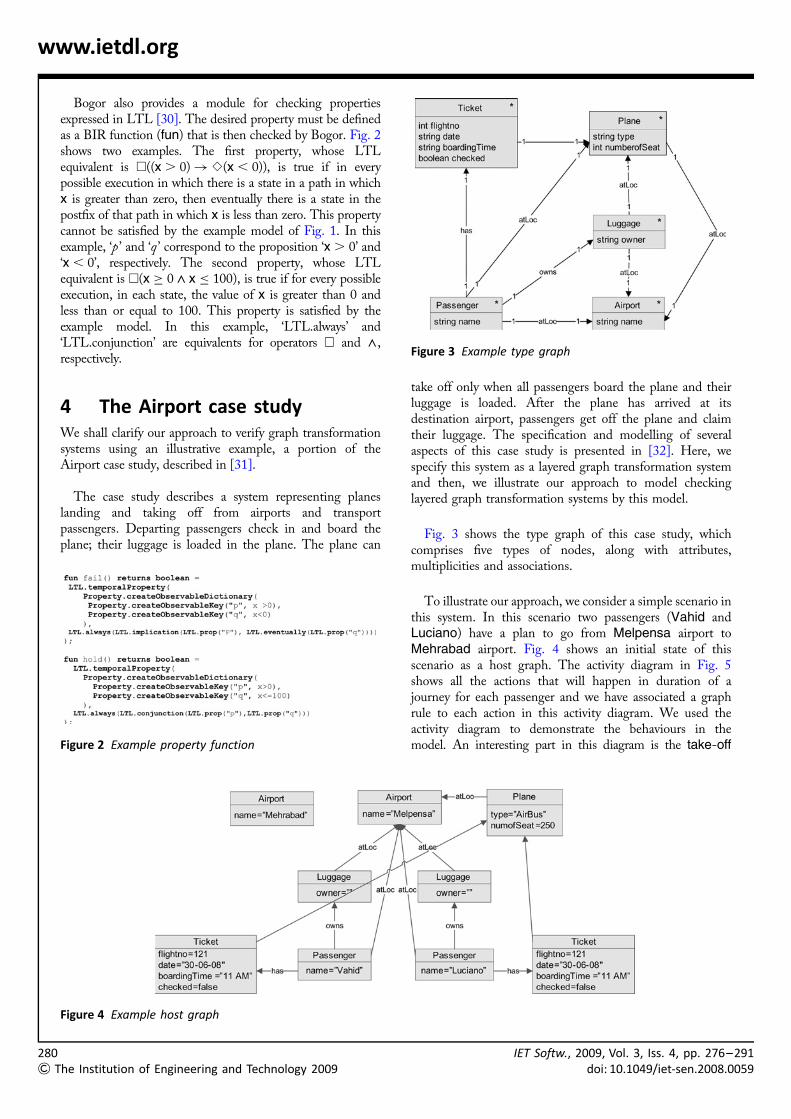
Bogor also provides a module for checking propertiesexpressed in LTL [30]. The desired property must be definedas a BIR function (fun) that is then checked by Bogor. Fig. 2shows two examples. The first property, whose LTLequivalent is A((x . 0)! S(x , 0)), is true if in everypossible execution in which there is a state in a path in whichx is greater than zero, then eventually there is a state in thepostfix of that path in which x is less than zero. This propertycannot be satisfied by the example model of Fig. 1. In thisexample, ‘p ’ and ‘q ’ correspond to the proposition ‘x . 0’ and‘x , 0’, respectively. The second property, whose LTLequivalent is A(x � 0 ^ x � 100), is true if for every possibleexecution, in each state, the value of x is greater than 0 andless than or equal to 100. This property is satisfied by theexample model. In this example, ‘LTL.always’ and‘LTL.conjunction’ are equivalents for operators A and ^,respectively.
4 The Airport case studyWe shall clarify our approach to verify graph transformationsystems using an illustrative example, a portion of theAirport case study, described in [31].
The case study describes a system representing planeslanding and taking off from airports and transportpassengers. Departing passengers check in and board theplane; their luggage is loaded in the plane. The plane can
Figure 2 Example property function
he Institution of Engineering and Technology 2009
take off only when all passengers board the plane and theirluggage is loaded. After the plane has arrived at itsdestination airport, passengers get off the plane and claimtheir luggage. The specification and modelling of severalaspects of this case study is presented in [32]. Here, wespecify this system as a layered graph transformation systemand then, we illustrate our approach to model checkinglayered graph transformation systems by this model.
Fig. 3 shows the type graph of this case study, whichcomprises five types of nodes, along with attributes,multiplicities and associations.
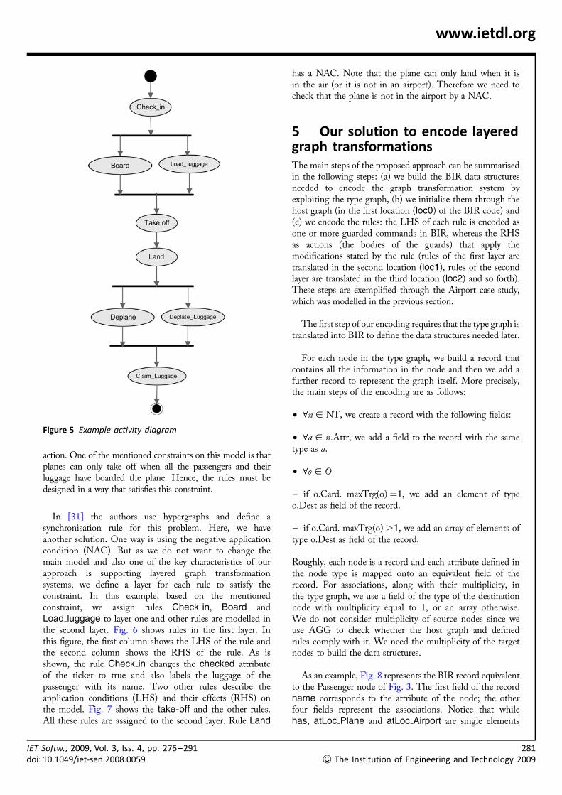
To illustrate our approach, we consider a simple scenario inthis system. In this scenario two passengers (Vahid andLuciano) have a plan to go from Melpensa airport toMehrabad airport. Fig. 4 shows an initial state of thisscenario as a host graph. The activity diagram in Fig. 5shows all the actions that will happen in duration of ajourney for each passenger and we have associated a graphrule to each action in this activity diagram. We used theactivity diagram to demonstrate the behaviours in themodel. An interesting part in this diagram is the take-off
Figure 3 Example type graph
Figure 4 Example host graph
IET Softw., 2009, Vol. 3, Iss. 4, pp. 276–291doi: 10.1049/iet-sen.2008.0059
IETdoi:
www.ietdl.org
action. One of the mentioned constraints on this model is thatplanes can only take off when all the passengers and theirluggage have boarded the plane. Hence, the rules must bedesigned in a way that satisfies this constraint.
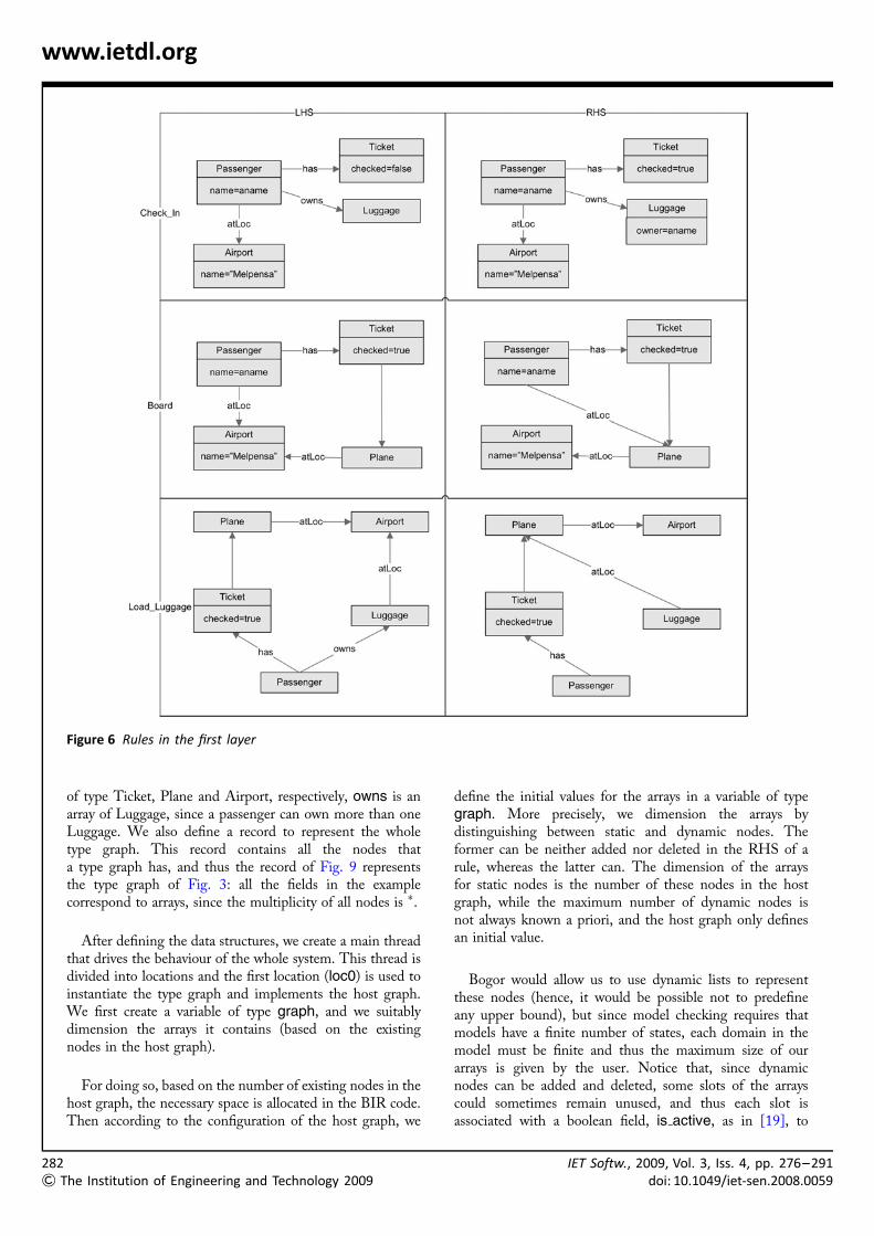
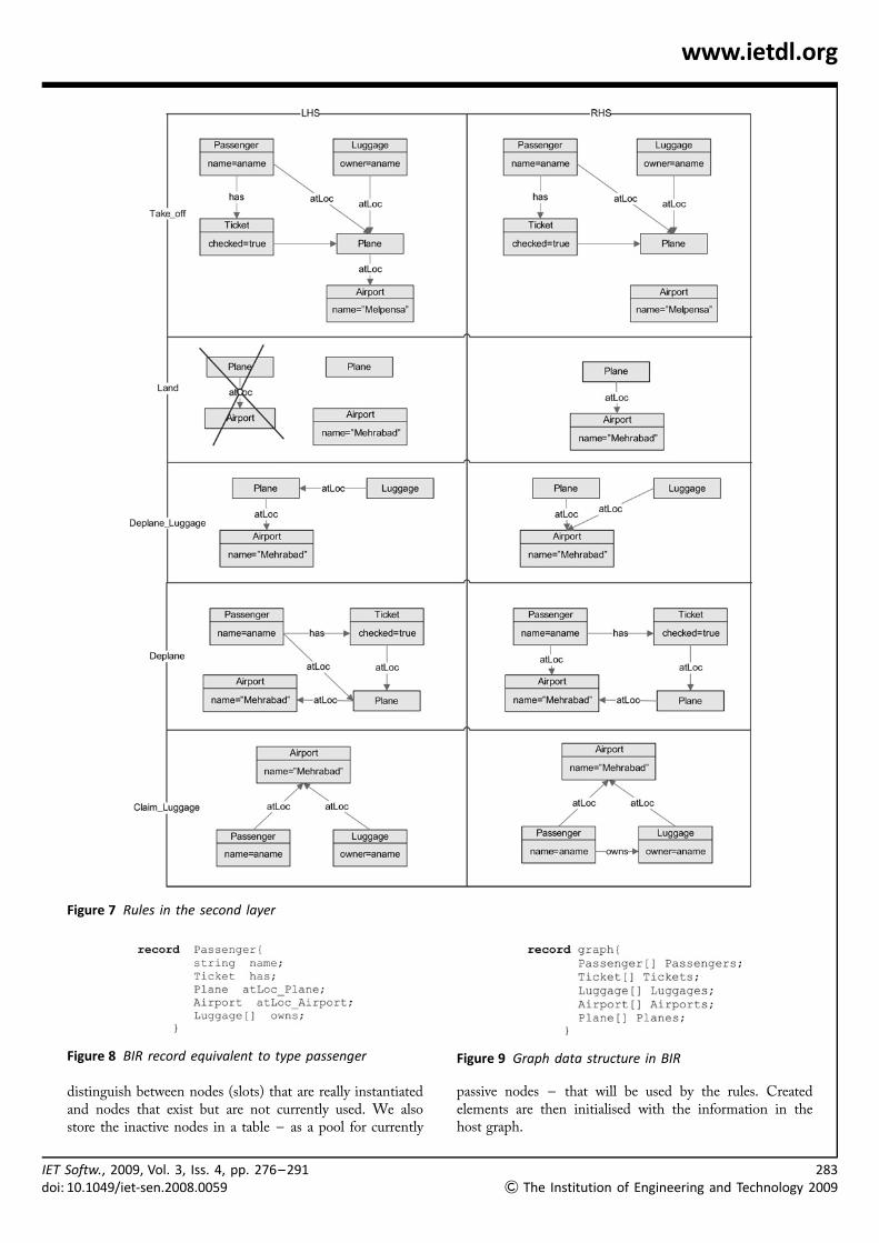
In [31] the authors use hypergraphs and define asynchronisation rule for this problem. Here, we haveanother solution. One way is using the negative applicationcondition (NAC). But as we do not want to change themain model and also one of the key characteristics of ourapproach is supporting layered graph transformationsystems, we define a layer for each rule to satisfy theconstraint. In this example, based on the mentionedconstraint, we assign rules Check in, Board andLoad luggage to layer one and other rules are modelled inthe second layer. Fig. 6 shows rules in the first layer. Inthis figure, the first column shows the LHS of the rule andthe second column shows the RHS of the rule. As isshown, the rule Check in changes the checked attributeof the ticket to true and also labels the luggage of thepassenger with its name. Two other rules describe theapplication conditions (LHS) and their effects (RHS) onthe model. Fig. 7 shows the take-off and the other rules.All these rules are assigned to the second layer. Rule Land
Figure 5 Example activity diagram
Softw., 2009, Vol. 3, Iss. 4, pp. 276–29110.1049/iet-sen.2008.0059
has a NAC. Note that the plane can only land when it isin the air (or it is not in an airport). Therefore we need tocheck that the plane is not in the airport by a NAC.
5 Our solution to encode layeredgraph transformationsThe main steps of the proposed approach can be summarisedin the following steps: (a) we build the BIR data structuresneeded to encode the graph transformation system byexploiting the type graph, (b) we initialise them through thehost graph (in the first location (loc0) of the BIR code) and(c) we encode the rules: the LHS of each rule is encoded asone or more guarded commands in BIR, whereas the RHSas actions (the bodies of the guards) that apply themodifications stated by the rule (rules of the first layer aretranslated in the second location (loc1), rules of the secondlayer are translated in the third location (loc2) and so forth).These steps are exemplified through the Airport case study,which was modelled in the previous section.
The first step of our encoding requires that the type graph istranslated into BIR to define the data structures needed later.
For each node in the type graph, we build a record thatcontains all the information in the node and then we add afurther record to represent the graph itself. More precisely,the main steps of the encoding are as follows:
† 8n [ NT, we create a record with the following fields:
† 8a [ n:Attr, we add a field to the record with the sametype as a.
† 8o [ O
– if o.Card. maxTrg(o) ¼1, we add an element of typeo.Dest as field of the record.
– if o.Card. maxTrg(o) .1, we add an array of elements oftype o.Dest as field of the record.
Roughly, each node is a record and each attribute defined inthe node type is mapped onto an equivalent field of therecord. For associations, along with their multiplicity, inthe type graph, we use a field of the type of the destinationnode with multiplicity equal to 1, or an array otherwise.We do not consider multiplicity of source nodes since weuse AGG to check whether the host graph and definedrules comply with it. We need the multiplicity of the targetnodes to build the data structures.
As an example, Fig. 8 represents the BIR record equivalentto the Passenger node of Fig. 3. The first field of the recordname corresponds to the attribute of the node; the otherfour fields represent the associations. Notice that whilehas, atLoc Plane and atLoc Airport are single elements
281
& The Institution of Engineering and Technology 2009
282
& T
www.ietdl.org
Figure 6 Rules in the first layer
of type Ticket, Plane and Airport, respectively, owns is anarray of Luggage, since a passenger can own more than oneLuggage. We also define a record to represent the wholetype graph. This record contains all the nodes thata type graph has, and thus the record of Fig. 9 representsthe type graph of Fig. 3: all the fields in the examplecorrespond to arrays, since the multiplicity of all nodes is �.
After defining the data structures, we create a main threadthat drives the behaviour of the whole system. This thread isdivided into locations and the first location (loc0) is used toinstantiate the type graph and implements the host graph.We first create a variable of type graph, and we suitablydimension the arrays it contains (based on the existingnodes in the host graph).
For doing so, based on the number of existing nodes in thehost graph, the necessary space is allocated in the BIR code.Then according to the configuration of the host graph, we
he Institution of Engineering and Technology 2009
define the initial values for the arrays in a variable of typegraph. More precisely, we dimension the arrays bydistinguishing between static and dynamic nodes. Theformer can be neither added nor deleted in the RHS of arule, whereas the latter can. The dimension of the arraysfor static nodes is the number of these nodes in the hostgraph, while the maximum number of dynamic nodes isnot always known a priori, and the host graph only definesan initial value.
Bogor would allow us to use dynamic lists to representthese nodes (hence, it would be possible not to predefineany upper bound), but since model checking requires thatmodels have a finite number of states, each domain in themodel must be finite and thus the maximum size of ourarrays is given by the user. Notice that, since dynamicnodes can be added and deleted, some slots of the arrayscould sometimes remain unused, and thus each slot isassociated with a boolean field, is active, as in [19], to
IET Softw., 2009, Vol. 3, Iss. 4, pp. 276–291doi: 10.1049/iet-sen.2008.0059
IETdoi:
www.ietdl.org
Figure 7 Rules in the second layer
distinguish between nodes (slots) that are really instantiatedand nodes that exist but are not currently used. We alsostore the inactive nodes in a table – as a pool for currently
Figure 8 BIR record equivalent to type passenger
Softw., 2009, Vol. 3, Iss. 4, pp. 276–29110.1049/iet-sen.2008.0059
passive nodes – that will be used by the rules. Createdelements are then initialised with the information in thehost graph.
Figure 9 Graph data structure in BIR
283
& The Institution of Engineering and Technology 2009
284
& T
www.ietdl.org
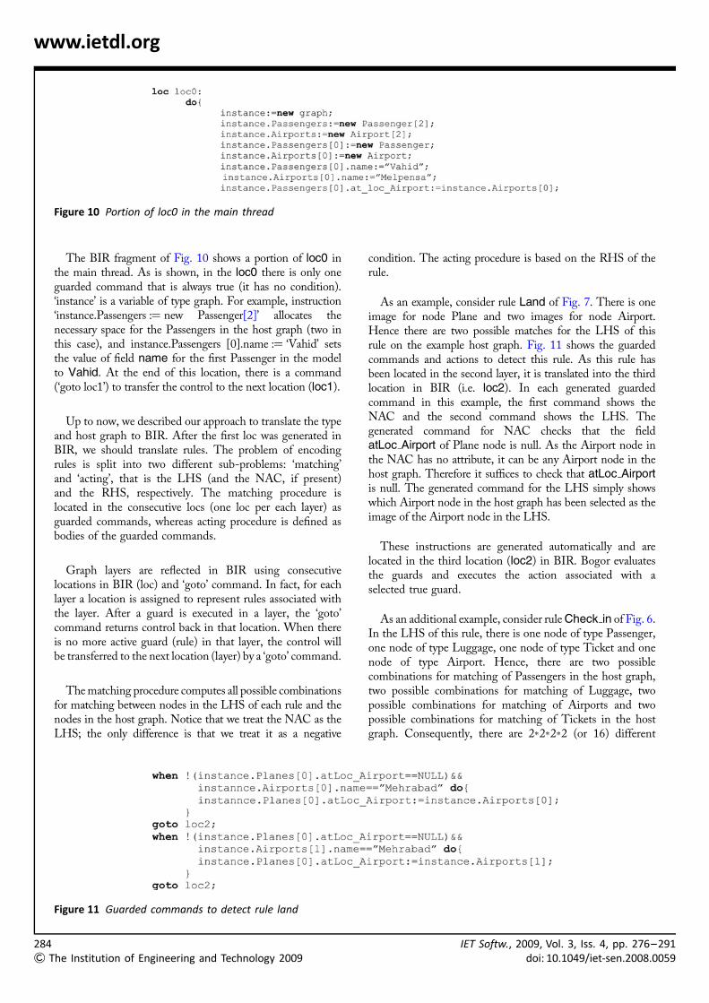
Figure 10 Portion of loc0 in the main thread
The BIR fragment of Fig. 10 shows a portion of loc0 inthe main thread. As is shown, in the loc0 there is only oneguarded command that is always true (it has no condition).‘instance’ is a variable of type graph. For example, instruction‘instance.Passengers :¼ new Passenger[2]’ allocates thenecessary space for the Passengers in the host graph (two inthis case), and instance.Passengers [0].name :¼ ‘Vahid’ setsthe value of field name for the first Passenger in the modelto Vahid. At the end of this location, there is a command(‘goto loc1’) to transfer the control to the next location (loc1).
Up to now, we described our approach to translate the typeand host graph to BIR. After the first loc was generated inBIR, we should translate rules. The problem of encodingrules is split into two different sub-problems: ‘matching’and ‘acting’, that is the LHS (and the NAC, if present)and the RHS, respectively. The matching procedure islocated in the consecutive locs (one loc per each layer) asguarded commands, whereas acting procedure is defined asbodies of the guarded commands.
Graph layers are reflected in BIR using consecutivelocations in BIR (loc) and ‘goto’ command. In fact, for eachlayer a location is assigned to represent rules associated withthe layer. After a guard is executed in a layer, the ‘goto’command returns control back in that location. When thereis no more active guard (rule) in that layer, the control willbe transferred to the next location (layer) by a ‘goto’ command.
The matching procedure computes all possible combinationsfor matching between nodes in the LHS of each rule and thenodes in the host graph. Notice that we treat the NAC as theLHS; the only difference is that we treat it as a negative
he Institution of Engineering and Technology 2009
condition. The acting procedure is based on the RHS of therule.
As an example, consider rule Land of Fig. 7. There is oneimage for node Plane and two images for node Airport.Hence there are two possible matches for the LHS of thisrule on the example host graph. Fig. 11 shows the guardedcommands and actions to detect this rule. As this rule hasbeen located in the second layer, it is translated into the thirdlocation in BIR (i.e. loc2). In each generated guardedcommand in this example, the first command shows theNAC and the second command shows the LHS. Thegenerated command for NAC checks that the fieldatLoc Airport of Plane node is null. As the Airport node inthe NAC has no attribute, it can be any Airport node in thehost graph. Therefore it suffices to check that atLoc Airportis null. The generated command for the LHS simply showswhich Airport node in the host graph has been selected as theimage of the Airport node in the LHS.
These instructions are generated automatically and arelocated in the third location (loc2) in BIR. Bogor evaluatesthe guards and executes the action associated with aselected true guard.
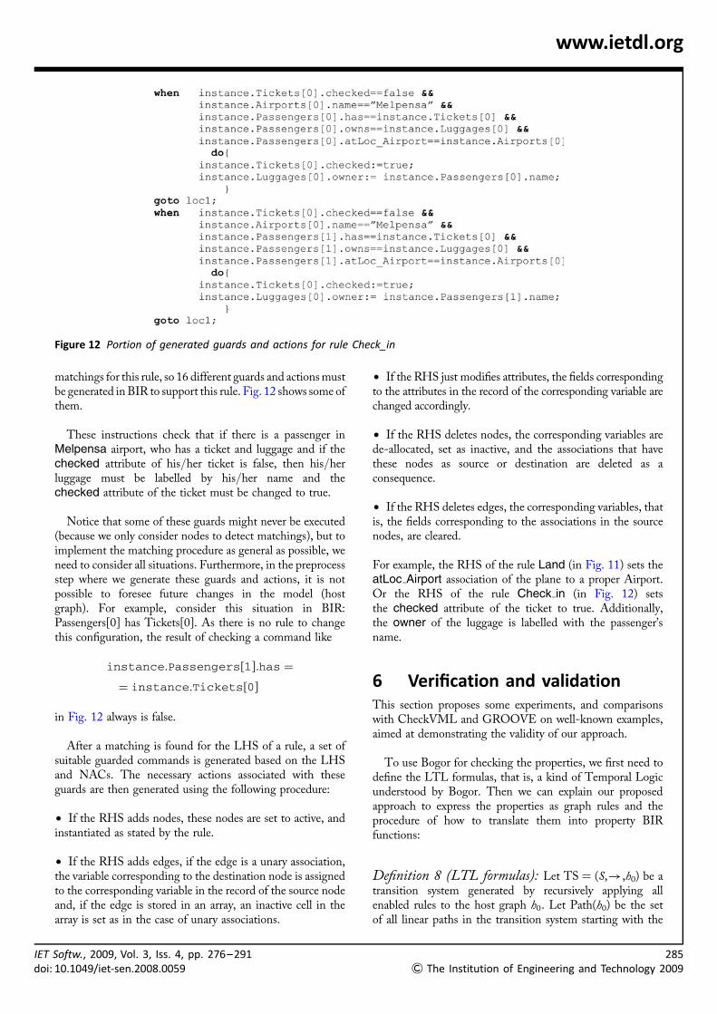
As an additional example, consider rule Check in of Fig. 6.In the LHS of this rule, there is one node of type Passenger,one node of type Luggage, one node of type Ticket and onenode of type Airport. Hence, there are two possiblecombinations for matching of Passengers in the host graph,two possible combinations for matching of Luggage, twopossible combinations for matching of Airports and twopossible combinations for matching of Tickets in the hostgraph. Consequently, there are 2�2�2�2 (or 16) different
Figure 11 Guarded commands to detect rule land
IET Softw., 2009, Vol. 3, Iss. 4, pp. 276–291doi: 10.1049/iet-sen.2008.0059
IETdoi
www.ietdl.org
Figure 12 Portion of generated guards and actions for rule Check_in
matchings for this rule, so 16 different guards and actions mustbe generated in BIR to support this rule. Fig. 12 shows some ofthem.
These instructions check that if there is a passenger inMelpensa airport, who has a ticket and luggage and if thechecked attribute of his/her ticket is false, then his/herluggage must be labelled by his/her name and thechecked attribute of the ticket must be changed to true.
Notice that some of these guards might never be executed(because we only consider nodes to detect matchings), but toimplement the matching procedure as general as possible, weneed to consider all situations. Furthermore, in the preprocessstep where we generate these guards and actions, it is notpossible to foresee future changes in the model (hostgraph). For example, consider this situation in BIR:Passengers[0] has Tickets[0]. As there is no rule to changethis configuration, the result of checking a command like
instance:Passengers[1]:has ¼
¼ instance:Tickets[0]
in Fig. 12 always is false.
After a matching is found for the LHS of a rule, a set ofsuitable guarded commands is generated based on the LHSand NACs. The necessary actions associated with theseguards are then generated using the following procedure:
† If the RHS adds nodes, these nodes are set to active, andinstantiated as stated by the rule.
† If the RHS adds edges, if the edge is a unary association,the variable corresponding to the destination node is assignedto the corresponding variable in the record of the source nodeand, if the edge is stored in an array, an inactive cell in thearray is set as in the case of unary associations.
Softw., 2009, Vol. 3, Iss. 4, pp. 276–291: 10.1049/iet-sen.2008.0059
† If the RHS just modifies attributes, the fields correspondingto the attributes in the record of the corresponding variable arechanged accordingly.
† If the RHS deletes nodes, the corresponding variables arede-allocated, set as inactive, and the associations that havethese nodes as source or destination are deleted as aconsequence.
† If the RHS deletes edges, the corresponding variables, thatis, the fields corresponding to the associations in the sourcenodes, are cleared.
For example, the RHS of the rule Land (in Fig. 11) sets theatLoc Airport association of the plane to a proper Airport.Or the RHS of the rule Check in (in Fig. 12) setsthe checked attribute of the ticket to true. Additionally,the owner of the luggage is labelled with the passenger’sname.
6 Verification and validationThis section proposes some experiments, and comparisonswith CheckVML and GROOVE on well-known examples,aimed at demonstrating the validity of our approach.
To use Bogor for checking the properties, we first need todefine the LTL formulas, that is, a kind of Temporal Logicunderstood by Bogor. Then we can explain our proposedapproach to express the properties as graph rules and theprocedure of how to translate them into property BIRfunctions:
Definition 8 (LTL formulas): Let TS ¼ (S,!,h0) be atransition system generated by recursively applying allenabled rules to the host graph h0. Let Path(h0) be the setof all linear paths in the transition system starting with the
285
& The Institution of Engineering and Technology 2009
286
&
www.ietdl.org
state h0, and let p be some atomic propositions. Then
TS o G(p)(or A(p)):, 8h0h1h2 . . . [ Path(h0),
8k [ IN: p holds in hk
TS o F(p)(or S (p)):, 8h0h1h2 . . . [ Path(h0),
9k [ IN: p holds in hk
Note that this is only a subset of LTL. In case of finite paths,k has to be restricted to the length of the path.
Now, we should express desired properties as propositions.For example, consider this safety property on the airportexample: ‘A passenger can never board, when his/her tickethas not already been checked’, or formally
8p: passenger, 8h0h1h2 . . . [ Path(h0), not exists k [
IN: ticket( p):checked ¼ false ^ p:atLoc ¼ plane holds in hk
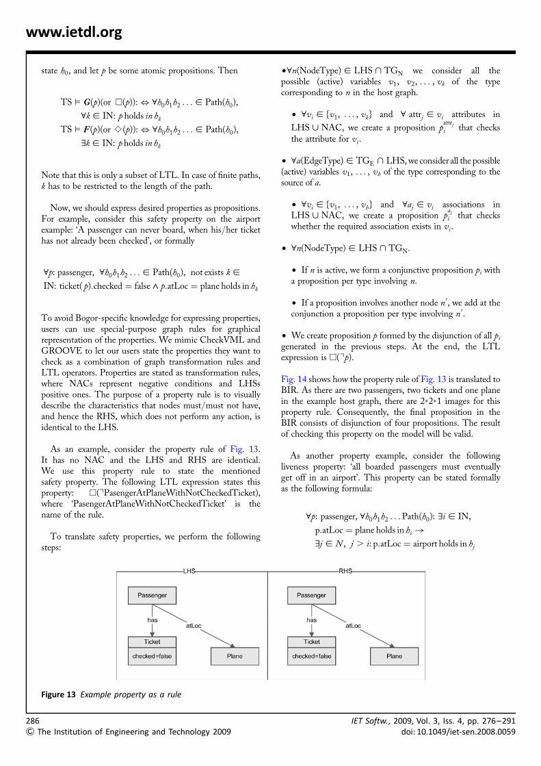
To avoid Bogor-specific knowledge for expressing properties,users can use special-purpose graph rules for graphicalrepresentation of the properties. We mimic CheckVML andGROOVE to let our users state the properties they want tocheck as a combination of graph transformation rules andLTL operators. Properties are stated as transformation rules,where NACs represent negative conditions and LHSspositive ones. The purpose of a property rule is to visuallydescribe the characteristics that nodes must/must not have,and hence the RHS, which does not perform any action, isidentical to the LHS.
As an example, consider the property rule of Fig. 13.It has no NAC and the LHS and RHS are identical.We use this property rule to state the mentionedsafety property. The following LTL expression states thisproperty: A(1PasengerAtPlaneWithNotCheckedTicket),where ‘PasengerAtPlaneWithNotCheckedTicket’ is thename of the rule.
To translate safety properties, we perform the followingsteps:
The Institution of Engineering and Technology 2009
†8n(NodeType) [ LHS > TGN we consider all thepossible (active) variables v1, v2, . . . , vk of the typecorresponding to n in the host graph.
† 8vi [ {v1, . . . , vk} and 8 attrj [ vi attributes in
LHS < NAC, we create a proposition pattrj
i that checksthe attribute for vi .
† 8a(EdgeType) [ TGE > LHS, we consider all the possible(active) variables v1, . . . , vh of the type corresponding to thesource of a.
† 8vi [ {v1, . . . , vh} and 8aj [ vi associations inLHS < NAC, we create a proposition p
aj
i that checkswhether the required association exists in vi.
† 8n(NodeType) [ LHS > TGN.
† If n is active, we form a conjunctive proposition pi witha proposition per type involving n.
† If a proposition involves another node n0, we add at theconjunction a proposition per type involving n0.
† We create proposition p formed by the disjunction of all pi
generated in the previous steps. At the end, the LTLexpression is A(1p).
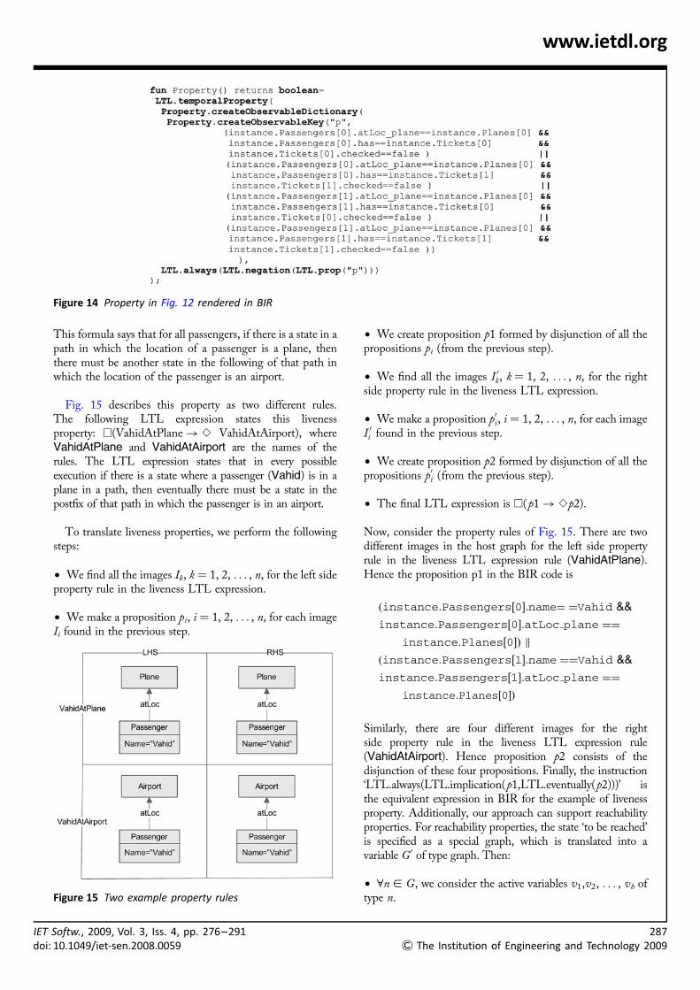
Fig. 14 shows how the property rule of Fig. 13 is translated toBIR. As there are two passengers, two tickets and one planein the example host graph, there are 2�2�1 images for thisproperty rule. Consequently, the final proposition in theBIR consists of disjunction of four propositions. The resultof checking this property on the model will be valid.
As another property example, consider the followingliveness property: ‘all boarded passengers must eventuallyget off in an airport’. This property can be stated formallyas the following formula:
8p: passenger, 8h0h1h2 . . . Path(h0): 9i [ IN,
p:atLoc ¼ plane holds in hi !
9j [ N , j . i: p:atLoc ¼ airport holds in hj
Figure 13 Example property as a rule
IET Softw., 2009, Vol. 3, Iss. 4, pp. 276–291doi: 10.1049/iet-sen.2008.0059
IETdoi:
www.ietdl.org
Figure 14 Property in Fig. 12 rendered in BIR
This formula says that for all passengers, if there is a state in apath in which the location of a passenger is a plane, thenthere must be another state in the following of that path inwhich the location of the passenger is an airport.
Fig. 15 describes this property as two different rules.The following LTL expression states this livenessproperty: A(VahidAtPlane! S VahidAtAirport), whereVahidAtPlane and VahidAtAirport are the names of therules. The LTL expression states that in every possibleexecution if there is a state where a passenger (Vahid) is in aplane in a path, then eventually there must be a state in thepostfix of that path in which the passenger is in an airport.
To translate liveness properties, we perform the followingsteps:
† We find all the images Ik, k ¼ 1, 2, . . . , n, for the left sideproperty rule in the liveness LTL expression.
† We make a proposition pi, i ¼ 1, 2, . . . , n, for each imageIi found in the previous step.
Figure 15 Two example property rules
Softw., 2009, Vol. 3, Iss. 4, pp. 276–29110.1049/iet-sen.2008.0059
† We create proposition p1 formed by disjunction of all thepropositions pi (from the previous step).
† We find all the images I 0k, k ¼ 1, 2, . . . , n, for the rightside property rule in the liveness LTL expression.
† We make a proposition p0i, i ¼ 1, 2, . . . , n, for each imageI 0i found in the previous step.
† We create proposition p2 formed by disjunction of all thepropositions p0i (from the previous step).
† The final LTL expression is A(p1! Sp2).
Now, consider the property rules of Fig. 15. There are twodifferent images in the host graph for the left side propertyrule in the liveness LTL expression rule (VahidAtPlane).Hence the proposition p1 in the BIR code is
ðinstance:Passengers½0�:name¼ ¼Vahid &&
instance:Passengers½0�:atLoc plane ¼¼
instance:Planes½0�Þ k
ðinstance:Passengers½1�:name ¼¼Vahid &&
instance:Passengers½1�:atLoc plane ¼¼
instance:Planes½0�Þ
Similarly, there are four different images for the rightside property rule in the liveness LTL expression rule(VahidAtAirport). Hence proposition p2 consists of thedisjunction of these four propositions. Finally, the instruction‘LTL.always(LTL.implication(p1,LTL.eventually(p2)))’ isthe equivalent expression in BIR for the example of livenessproperty. Additionally, our approach can support reachabilityproperties. For reachability properties, the state ‘to be reached’is specified as a special graph, which is translated into avariable G0 of type graph. Then:
† 8n [ G, we consider the active variables v1,v2, . . . , vh oftype n.
287
& The Institution of Engineering and Technology 2009

288&
www.ietdl.org
† 8n0 [ G0, if n0 has the same type as n, we consider theactive variables v1,v2, . . . , vk of type n:
– 8vi [ {v1, . . . , vh}, v0j [ {v1, . . . , vk}, we create aproposition P i
j that compares vi and v0j
† We create ST as a disjunction of conjunctions, where eachconjunction is formed by exactly one proposition for eachattribute and association of nodes in G. In the end, wegenerate the LTL expression 1(A(1ST)).
6.1 Performance analysis andbenchmarking
To compare our approach with existing ones, weimplemented five different case studies:
1. The well-known dining philosophers problem, presentedin [20].
2. The concurrent append example presented in [20]. In thisexample, two, three or four nodes are added concurrently atthe end of a linked list. For example 3:7 in Table 1 showsthat three nodes are added to a list containing seven nodes,in parallel.
3. The shopping cart example, presented in [33]. In thisexample, the process of purchasing goods by customers in amarket has been modelled as a graph transformation system.
4. The airport case study, introduced in Section 4.
5. The SmartCar example specified as service-orientedarchitecture in [34]. This example is a highly dynamic andbig model. It contains nearly 30 graph rules, a host graphinitially with 40 nodes and nearly 20 dynamic nodes thatare added to the host graph while the system evolves. In[34] the authors present an approach to model service-oriented architectures as a graph transformation system.Then to verify the designed model, they cannot use modelchecking and they do some experiments by simulation.Because this model is a big and dynamic model, existingtools for verification graph transformations are not capableof verifying it. By simulation, they only check that aspecific state is reachable. But by our approach, we cancheck different properties on this model.
Our experiments were run on a 3 GHz Pentium IV processorwith 1 GB of memory, whereas for CheckVML, we use theresults in [14], where they used a 3 GHz Pentium IVprocessor with 1 GB of memory, and as for GROOVE, weused the results provided by the GROOVE group(obtained on GROOVE 1.4.2 with a 3.2 GHz processorwith 500 MB of memory).
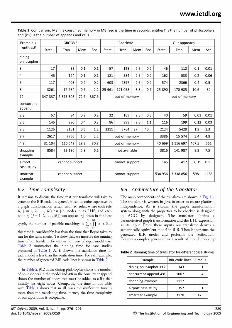
Table 1 summarises the results obtained with our approachand compares them with CheckVML and GROOVE. Thetable shows that for the dining philosophers, our approach
The Institution of Engineering and Technology 2009
is similar to CheckVML but weaker than GROOVE. Thebiggest model for dining philosophers, which our approachcan verify (on the same machine), is a model with 11philosophers. In the case of the concurrent appendexample, our approach is better than CheckVML withrespect to both memory usage and the time it takes to run.Compared with GROOVE, in this example our approachin most of the cases uses more memory and generates morestates and transitions than GROOVE. The use of memorycan easily be explained with the need to manage attributedgraphs. But as our approach is designed to handleattributed type graphs (i.e. Shopping, SmartCarexamples and Airport case studies) and layered graphtransformation systems (i.e. the Airport case study), itproves its efficiency in the next three case studies (last threerows of the table).
Compared to CheckVML, our approach is more efficientin all the cases except in the dining philosophers (where theresult is similar). Unfortunately, CheckVML is not publiclyavailable now; therefore we could not test the shoppingexample, but, as the authors mentioned in [20],CheckVML has some drawbacks for dynamic cases andthis case study also is a dynamic model. Furthermore,CheckVML cannot handle layered graph transformationspecifications like the Airport case study (in contrast withour approach).
To demonstrate the ability of our proposed approach inchecking a variety of properties, we implemented theexamples in [35, 36]. In these works, the authors describe aformal semantics for dynamic metamodelling with graphtransformation systems and, as an example, they mention aformal semantics for activity diagrams based on token flowsemantics to model and analyse workflows. They useGROOVE and define a liveness property based on tokensemantics and, at the end, they check whether activitydiagrams are live. As they mention, their approach onlychecks whether the tokens in all paths reach the final nodein the activity diagram and they cannot check the livenessproperty of a single activity node in the diagram. Again, weimplemented this example with our approach in [37] andbesides being able to check liveness for a complete activitydiagram, we also checked the liveness for all the nodes inthe model. We do not want to claim that our approach cancheck every property, but we believe it can check a widerange of properties.
Although the main idea of our approach is similar toCheckVML, there are many differences in the details. Oneof them, which highly impacts the performance of ourapproach, is the way we manage dynamic nodes and edges.As mentioned before, we store a graph as a record in BIRand use a linear array for each node type in this record.Moreover, the use of the navigation support provided byBogor to handle associations and attributes furtherimproves the efficiency of the proposal.
IET Softw., 2009, Vol. 3, Iss. 4, pp. 276–291doi: 10.1049/iet-sen.2008.0059
IETdo
www.ietdl.org
Table 1 Comparison: Mem is consumed memory in MB, Sec is the time in seconds, entities# is the number of philosophersand (x:y) is the number of appends and cells
Exampleþentities#
GROOVE CheckVML Our approach
State Tran Mem Sec State Tran Mem Sec State Tran Mem Sec
diningphilosopher
3 17 35 0.1 0.1 57 125 2.6 0.2 46 112 0.1 0.01
4 45 124 0.1 0.1 181 554 2.6 0.2 162 533 0.2 0.06
5 117 403 0.2 0.2 603 2397 2.6 0.2 574 2366 0.4 0.5
8 3261 17 984 0.6 2.2 25 961 171 058 8.8 0.6 25 890 170 985 10.6 32
12 347 337 2 873 308 72.6 367.6 out of memory out of memory
concurrentappend
2.3 57 94 0.2 0.2 22 169 2.6 0.5 40 59 0.01 0.01
2.5 145 290 0.4 0.3 86 395 2.6 1.1 116 199 0.12 0.03
3.5 1125 3161 0.6 1.2 3311 5764 37 40 2124 5428 1.3 1.3
3.7 2617 7766 1.0 2.2 out of memory 3386 15 574 5.4 4.8
4.8 31 104 116 642 28.3 30.8 out of memory 40 669 1 116 697 467.5 561
shoppingexample
8584 23 196 5.9 6.1 not available 3816 141 987 8.9 7.5
airportcase study
cannot support cannot support 145 412 0.15 0.1
smartcarexample
cannot support cannot support 538 936 3 338 856 598 1186
i:
6.2 Time complexity
It remains to discuss the time that our translator will take togenerate the BIR code. In general, it can be quite expensive: ina graph transformation system with jRj rules, where each ruleRi (i ¼ 1, 2, . . . , jRj) has jRij nodes in its LHS, and eachnode nj ( j ¼ 1, 2, . . . , jRij) can appear jnjj times in the host
graph, the number of possible matchings isPjRj
i¼1
(QjRi j
j¼1
jnj j). But
this time is considerably less than the time that Bogor takes torun for the same model. To show this, we measure the runningtime of our translator for various numbers of input model size.Table 2 summarises the running time for case studiespresented in Table 1. As is shown, the translation time foreach model is less than the verification time. For each example,the number of generated BIR code lines is shown in Table 2.
In Table 2, #12 in the dining philosopher shows the numberof philosophers in the model and 4:8 in the concurrent appendshows the number of nodes that must be added to a list thatinitially has eight nodes. Comparing the time in this tablewith Table 1 shows that in all cases the verification time ismore than the translating time. Hence, the time complexityof our algorithms is acceptable.
Softw., 2009, Vol. 3, Iss. 4, pp. 276–29110.1049/iet-sen.2008.0059
6.3 Architecture of the translator
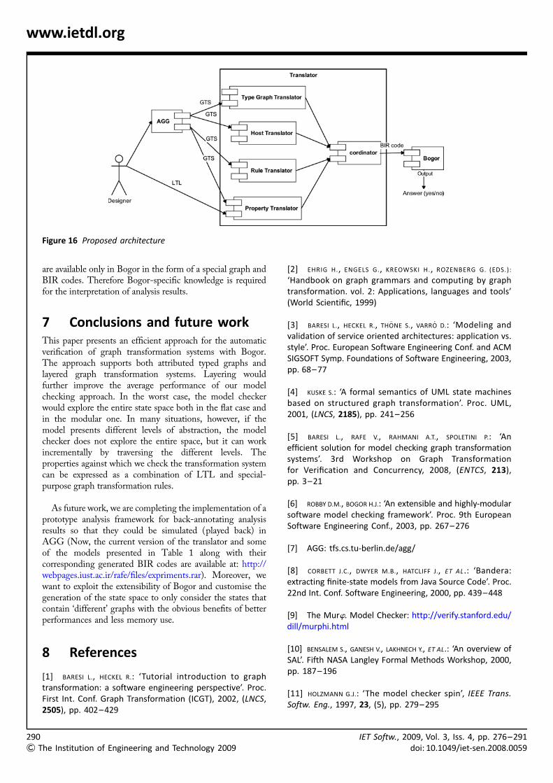
The main components of the translator are shown in Fig. 16.The translator is written in Java in order to ensure platformindependence. As is shown, the graph transformationsystem along with the properties to be checked is designedin AGG by designers. The translator obtains aparameterised graph transformation and the LTL expressionas its input. From these inputs our translator derives asemantically equivalent model in BIR. Then Bogor runs thegenerated BIR model and performs the verification.Counter-examples generated as a result of model checking
Table 2 Running time of translator for different case studies
Example BIR code lines Time, s
dining philosopher #12 343 1
concurrent append 4:8 1007 4
shopping example 1117 5
airport case study 352 1
smartcar example 3120 475
289
& The Institution of Engineering and Technology 2009
290
&
www.ietdl.org
Figure 16 Proposed architecture
are available only in Bogor in the form of a special graph andBIR codes. Therefore Bogor-specific knowledge is requiredfor the interpretation of analysis results.
7 Conclusions and future workThis paper presents an efficient approach for the automaticverification of graph transformation systems with Bogor.The approach supports both attributed typed graphs andlayered graph transformation systems. Layering wouldfurther improve the average performance of our modelchecking approach. In the worst case, the model checkerwould explore the entire state space both in the flat case andin the modular one. In many situations, however, if themodel presents different levels of abstraction, the modelchecker does not explore the entire space, but it can workincrementally by traversing the different levels. Theproperties against which we check the transformation systemcan be expressed as a combination of LTL and special-purpose graph transformation rules.
As future work, we are completing the implementation of aprototype analysis framework for back-annotating analysisresults so that they could be simulated (played back) inAGG (Now, the current version of the translator and someof the models presented in Table 1 along with theircorresponding generated BIR codes are available at: http://webpages.iust.ac.ir/rafe/files/expriments.rar). Moreover, wewant to exploit the extensibility of Bogor and customise thegeneration of the state space to only consider the states thatcontain ‘different’ graphs with the obvious benefits of betterperformances and less memory use.
8 References
[1] BARESI L., HECKEL R.: ‘Tutorial introduction to graphtransformation: a software engineering perspective’. Proc.First Int. Conf. Graph Transformation (ICGT), 2002, (LNCS,2505), pp. 402–429
The Institution of Engineering and Technology 2009
[2] EHRIG H., ENGELS G., KREOWSKI H., ROZENBERG G. (EDS.):
‘Handbook on graph grammars and computing by graphtransformation. vol. 2: Applications, languages and tools’(World Scientific, 1999)
[3] BARESI L., HECKEL R., THONE S., VARRO D.: ‘Modeling andvalidation of service oriented architectures: application vs.style’. Proc. European Software Engineering Conf. and ACMSIGSOFT Symp. Foundations of Software Engineering, 2003,pp. 68–77
[4] KUSKE S.: ‘A formal semantics of UML state machinesbased on structured graph transformation’. Proc. UML,2001, (LNCS, 2185), pp. 241–256
[5] BARESI L., RAFE V., RAHMANI A.T., SPOLETINI P.: ‘Anefficient solution for model checking graph transformationsystems’. 3rd Workshop on Graph Transformationfor Verification and Concurrency, 2008, (ENTCS, 213),pp. 3–21
[6] ROBBY D.M., BOGOR H.J.: ‘An extensible and highly-modularsoftware model checking framework’. Proc. 9th EuropeanSoftware Engineering Conf., 2003, pp. 267–276
[7] AGG: tfs.cs.tu-berlin.de/agg/
[8] CORBETT J.C., DWYER M.B., HATCLIFF J., ET AL.: ‘Bandera:extracting finite-state models from Java Source Code’. Proc.22nd Int. Conf. Software Engineering, 2000, pp. 439–448
[9] The Murw. Model Checker: http://verify.stanford.edu/dill/murphi.html
[10] BENSALEM S., GANESH V., LAKHNECH Y., ET AL.: ‘An overview ofSAL’. Fifth NASA Langley Formal Methods Workshop, 2000,pp. 187–196
[11] HOLZMANN G.J.: ‘The model checker spin’, IEEE Trans.Softw. Eng., 1997, 23, (5), pp. 279–295
IET Softw., 2009, Vol. 3, Iss. 4, pp. 276–291doi: 10.1049/iet-sen.2008.0059
IETdoi:
www.ietdl.org
[12] COMPTON K., GUREVICH Y., HUGGINS J., SHEN W.: ‘An automaticverification tool for UML’. Technical Report, CSE-TR-423–00,2000
[13] LATELLA D., MAJZIK I., MASSINK M.: ‘Automatic verification ofUML statechart diagrams using the SPIN modelchecker’,Form. Asp. Comput., 1999, 11, (6), pp. 637–664
[14] PALTOR I., LILIUS J.: ‘vUML: a tool for verifying UMLmodels’. Proc. 14th IEEE Int. Conf. Automated SoftwareEngineering, ASE’99, 1999
[15] HECKEL R.: ‘Compositional verification of reactivesystems specified by graph transformation’. Proc.Fundamental Approaches to Software Engineering (FASE),1998, (LNCS, 1382), pp. 138–153
[16] RENSINK A.: ‘The GROOVE simulator: a tool for state spacegeneration’. Applications of Graph Transformations withIndustrial Relevance (AGTIVE), 2004, (LNCS, 3062),pp. 479–485
[17] SCHMIDT A., VARRO D.: ‘CheckVML: A tool for modelchecking visual modeling languages’. Proc. 6th Int. Conf.Unified Modeling Language (UML), 2003, (LNCS, 2863),pp. 92–95
[18] KASTENBERG H.: ‘Towards attributed graphs in GROOVE’. Inthe first Workshop on Graph Transformation for Verificationand Concurrency, 2005, (ENTCS, 154), pp. 47–54
[19] SCHMIDT A.: ‘Model checking of visual modelinglanguages’. Master’s thesis, Budapest University ofTechnology, Hungary, 2004
[20] RENSINK A., SCHMIDT A., VARRO D.: ‘Model checking graphtransformations: a comparison of two approaches’. Proc.Second Int. Conf. Graph Transformation (ICGT), 2004,(LNCS, 3256), pp. 226–241
[21] GYAPAY S., SCHMIDT A., VARRO D.: ‘Joint optimization andreachability analysis in graph transformation systems withtime’. In the Int. Workshop on Graph Transformationand Visual Modeling Techniques, 2004, (ENTCS, 109),pp. 137–147
[22] BALDAN P., KONIG B.: ‘Approximating the behavior of graphtransformation systems’. Proc. First Int. Conf. GraphTransformation (ICGT), 2002, (LNCS, 2505), pp. 14–29
[23] BALDAN P., CORRADINI A., KONIG B.: ‘Verifying finite-stategraph grammars: an unfolding-based approach’. Proc. Int.Conf. Concurrency Theory (CONCUR), 2004, (LNCS, 3170),pp. 83–98
[24] DOTTI F.L., FOSS L., RIBEIRO L., SANTOS O.M.: ‘Verification ofobject-based distributed systems’. Proc. 6th Int. Conf.
Softw., 2009, Vol. 3, Iss. 4, pp. 276–29110.1049/iet-sen.2008.0059
Formal Methods for Open Object-based DistributedSystems, 2003, (LNCS, 2884), pp. 261–275
[25] FERREIRA A.P.L., FOSS L., RIBEIRO L.: ‘Formal verification ofobject-oriented graph grammars specifications’, Electron.Notes Theor. Comput. Sci., 2007, 175, pp. 101–114
[26] BARESI L., SPOLETINI P.: ‘On the use of alloy to analyze graphtransformation systems’. Proc. Third Int. Conf. GraphTransformations, (ICGT), 2006, (LNCS, 4178), pp. 306–320
[27] JACKSON D.: ‘Software abstractions: logic, language, andanalysis’ (The MIT Press, 2006)
[28] EHRIG H., PFENDER M., SCHNEIDER H.J.: ‘Graph grammars: analgebraic approach’. 14th Annual IEEE Symp. Switchingand Automata Theory, 1973, pp. 167–180
[29] BARESI L., GHEZZI C., MOTOLLA L.: ‘On accurate automaticverification of publish-subscribe architectures’. Proc. 29thInt. Conf. Software Engineering, 2007
[30] Bogor extensions for LTL checking: projects.cis.ksu.edu/projects/gudangbogor/
[31] BALDAN P., CORRADINI A., GADDUCCI F.: ‘Specifying andverifying UML activity diagrams via graph transformation’.Proc. Global Computing, 2004, (LNCS, 3267), pp. 18–33
[32] ANDERADE L., BALDAN P., BAUMEISTER H.: ‘AGILE: softwarearchitecture for mobility’. Proc. 16th Int. Workshop onAlgebraic Development Techniques, 2003, pp. 1–33
[33] HAUSMANN J.H., HECKEL R., TAENTZER G.: ‘Detection ofconflicting functional requirements in a use case-drivenapproach: a static analysis technique based on graphtransformation’. Proc. Int. Computer Software Engineering(ICSE), 2002, pp. 105–115
[34] BARESI L., HECKEL R., THONE S., VARRO D.: ‘Style-based modelingand refinement of service-oriented architectures: a graphtransformation-based approach’, J. Softw. Syst. Model.,2006, 5, pp. 187–207
[35] HAUSMANN J.H.: ‘Dynamic meta modeling: a semanticsdescription technique for visual modeling languages’. PhDthesis, University of Paderborn, Germany, 2005
[36] ENGELS G., SOLTENBORN C., WEHRHEIM H.: ‘Analysis of UMLactivities using dynamic meta modeling’. Proc. 9th IFIPInt. Conf. Formal Methods for Open Object-BasedDistributed Systems (FMOODS), (LNCS, 4468), pp. 76–90
[37] RAFE V., RAHMANI A.T.: ‘Formal analysis of workflows usingUML 2.0 activities and graph transformation systems’. Proc.5th Int. Colloquium on Theoretical Aspects of Computing(ICTAC), 2008, (LNCS, 5160), pp. 305–318
291
& The Institution of Engineering and Technology 2009