Towards a Long Endurance MAV
8
Towards a Long Endurance MAV Murat Bronz * , Jean Marc Moschetta † , Pascal Brisset ‡ , Michel Gorraz § Institut Sup´ erieur de l’A´ eronautique et de l’Espace, Toulouse, France and Ecole Nationale de l’Aviation Civile, Toulouse, France ABSTRACT A conceptual design and performance analysis method (Long Endurance Conceptual Design Program) for long-endurance mini-micro UAVs is presented. Recent long endurance oriented re- sults and achievements are looked through for possible usage for mini-micro scale. A real mission is also explained, whose objective is to accomplish a 200 km straight line flight au- tonomously with the smallest electric platform possible. Design phases of the platform by us- ing the presented method, flight tests and com- parison of the results are included. On the fol- lowing section a design study for long-endurance MAVs using a hybrid energy system combining solar energy and Lithium batteries and the ef- fect of size and cruise speed are investigated. We demonstrate that under a certain size, the use of solar energy becomes not useful at all. We con- clude with the study of a candidate design for EMAV09 Endurance Mission in the light of the rules and scoring of the mission. Keywords: Long Endurance, Solar Power, Sys- tem Design and Optimization, Paparazzi Autopi- lot I NTRODUCTION The number of the fields are increasing day by day which UAVs can take part in, but all of these fields have different and additional demands for their particular mission. These are pushing the limits of the UAVs to extremes by all means of disciplines such as structure, electronics, aerodynamics etc. Of course the operational costs are usually among the most important issues. By the help of miniaturization of the on- board electronics, it has become much more feasible to shrink the size of the UAVs which brings the cost advantage and operational simplicity as well. The biggest problem rise up for small UAVs is the energy sources which are not small enough to achieve the same en- durance than the big ones. For sure long-endurance capability * PhD Student, [email protected] † Professor in Aerodynamics, [email protected] ‡ Lecturer in Computer Science, [email protected] § Lecturer in Electronics, [email protected] is needed and a big advantage for any kind of mission. So we concentrate our effort on having a long-endurance mini-micro UAV. This paper will present the initial approach for a Long- endurance mini-micro UAV conceptual design, by introduc- ing the method and the Long Endurance Conceptual Design Program behind, some ideas for extracting energy which are planned for future work, candidate energy sources that are decided to be used, an example mission which has decided to be used for coefficient verification of the design program, and also the feasibility study of using the decided techniques for a MAV design. At the last part a candidate design for EMAV09 Endurance Mission will be studied with the rules and scoring in mind. 1 DESIGN STUDY FOR A LONG-ENDURANCE MINI -UAV The Design process has several phases, like conceptual, preliminary and detailed design. Generally in the concep- tual design phase of a UAV, a wide competitor-study accord- ing to the RFP of the mission can lead to quite close re- sults for the geometrical specifications of the design, which will be frozen on the final design. However on a design like long-endurance mini-UAV, as the concept has been newborn, competitor-study will either not be sufficient or not lead to an innovative design. So the key points of the challenge for a long-endurance Mini-UAV have been investigated and a Long-Endurance Conceptual Design Program (LECDP) has been developed and is presented briefly below. 1.1 Energy Sources At the scale of Mini and Micro UAVs, energy storage sys- tems become even more problematic than the bigger UAVs since it can reach 40 % of the total weight. Thus, a wide re- search of current state of the art for energy sources has been completed. However a brief look will be taken place in the paper. Battery technology keeps improving rapidly because of the huge demand of portable computers, cell phones and Ra- dio Control models. Currently Lithium-Polymer batteries are the most dominant ones in the market.They have a specific energy of 150 to 200 W h/kg. After scanning the whole en- velope for suitable battery technology (Table 1), Lithium- Polymer and Lithium-Sulfur 1 batteries were selected as the 1 www.sionpower.com 1
-
Upload
independent -
Category
Documents
-
view
2 -
download
0
Transcript of Towards a Long Endurance MAV

Towards a Long Endurance MAVMurat Bronz∗, Jean Marc Moschetta†, Pascal Brisset‡, Michel Gorraz§
Institut Superieur de l’Aeronautique et de l’Espace, Toulouse, Franceand
Ecole Nationale de l’Aviation Civile, Toulouse, France
ABSTRACT
A conceptual design and performance analysismethod (Long Endurance Conceptual DesignProgram) for long-endurance mini-micro UAVsis presented. Recent long endurance oriented re-sults and achievements are looked through forpossible usage for mini-micro scale. A realmission is also explained, whose objective isto accomplish a 200 km straight line flight au-tonomously with the smallest electric platformpossible. Design phases of the platform by us-ing the presented method, flight tests and com-parison of the results are included. On the fol-lowing section a design study for long-enduranceMAVs using a hybrid energy system combiningsolar energy and Lithium batteries and the ef-fect of size and cruise speed are investigated. Wedemonstrate that under a certain size, the use ofsolar energy becomes not useful at all. We con-clude with the study of a candidate design forEMAV09 Endurance Mission in the light of therules and scoring of the mission.
Keywords: Long Endurance, Solar Power, Sys-tem Design and Optimization, Paparazzi Autopi-lot
INTRODUCTION
The number of the fields are increasing day by day whichUAVs can take part in, but all of these fields have different andadditional demands for their particular mission. These arepushing the limits of the UAVs to extremes by all means ofdisciplines such as structure, electronics, aerodynamics etc.Of course the operational costs are usually among the mostimportant issues. By the help of miniaturization of the on-board electronics, it has become much more feasible to shrinkthe size of the UAVs which brings the cost advantage andoperational simplicity as well.
The biggest problem rise up for small UAVs is the energysources which are not small enough to achieve the same en-durance than the big ones. For sure long-endurance capability
∗PhD Student, [email protected]†Professor in Aerodynamics, [email protected]‡Lecturer in Computer Science, [email protected]§Lecturer in Electronics, [email protected]
is needed and a big advantage for any kind of mission. So weconcentrate our effort on having a long-endurance mini-microUAV.
This paper will present the initial approach for a Long-endurance mini-micro UAV conceptual design, by introduc-ing the method and the Long Endurance Conceptual DesignProgram behind, some ideas for extracting energy which areplanned for future work, candidate energy sources that aredecided to be used, an example mission which has decided tobe used for coefficient verification of the design program, andalso the feasibility study of using the decided techniques for aMAV design. At the last part a candidate design for EMAV09Endurance Mission will be studied with the rules and scoringin mind.
1 DESIGN STUDY FOR A LONG-ENDURANCEMINI-UAV
The Design process has several phases, like conceptual,preliminary and detailed design. Generally in the concep-tual design phase of a UAV, a wide competitor-study accord-ing to the RFP of the mission can lead to quite close re-sults for the geometrical specifications of the design, whichwill be frozen on the final design. However on a design likelong-endurance mini-UAV, as the concept has been newborn,competitor-study will either not be sufficient or not lead to aninnovative design.
So the key points of the challenge for a long-enduranceMini-UAV have been investigated and a Long-EnduranceConceptual Design Program (LECDP) has been developedand is presented briefly below.
1.1 Energy SourcesAt the scale of Mini and Micro UAVs, energy storage sys-
tems become even more problematic than the bigger UAVssince it can reach 40 % of the total weight. Thus, a wide re-search of current state of the art for energy sources has beencompleted. However a brief look will be taken place in thepaper.
Battery technology keeps improving rapidly because ofthe huge demand of portable computers, cell phones and Ra-dio Control models. Currently Lithium-Polymer batteries arethe most dominant ones in the market.They have a specificenergy of 150 to 200 Wh/kg. After scanning the whole en-velope for suitable battery technology (Table 1), Lithium-Polymer and Lithium-Sulfur 1 batteries were selected as the
1www.sionpower.com
1

Ni-Cd Ni-Mh Li-Po Li-SSpecific Energy (Wh/kg) 40 80 180 350
Energy Density (Wh/l) 100 300 300 350Specific Power (W/kg) 300 900 2800 600
Table 1: Battery specifications from different sources, num-bers for Li-Po are already tested and the numbers for Li-S arerely on the manufacturer.
two candidates for the calculations.Most recent long-endurance world records for small
UAVs, that are just using the energy stored on board, are bro-ken with Fuel-cells[1, 2]. Fuel-cells have high specific energyaround 1000 Wh/kg which is a great advantage. Howevertheir minimum initial system weight is around 1.9 kg 2. Al-though this system has sufficient energy for 10 hours of flightfor a UAV that has 2.5 m wing span 3, it doesn’t seem tobe feasible to realise a long-endurance UAV smaller than 2mwing span utilising fuel-cells at this stage because of the to-tal system weight. As we are dealing with a Mini-UAV whosemaximum dimensions doesn’t exceed 1 meter, we are obligedto wait and watch the new technology progress.
Benefiting from solar energy became very popular in thesense of green energy and also became feasible for small UAVactivities since the solar-cell technology improved a lot. Re-cent Silicon solar cells are thin, flexible and very light whilestill having a reasonably good efficiency. These propertiesmake them well suited for the small UAV activities. Aftera market search we obtained S-32 Silicon cells (Figure 1)which are the state of the art high efficiency, low weight sil-icon cells with an integrated by-pass diode (AzurSpace solarPower GMBH4).
S-32Open circuit V (mV ) 628Open circuit I (mA/cm2) 45.8Voltage @ Pmax (mV ) 528Current @ Pmax (mA/cm2) 43.4Avg. Efficiency (%) 16.9
Figure 1: Azur Space S-32 solar cell and its specifications.
There are several examples of applications about utilisingsolar energy in UAVs [3, 4] but recently most remarkable oneand the most closest one to Mini-UAV scale is for sure theSkySailor5 [5] which has accomplished a 27 hours continu-ous flight. Although Noth et al.[5] resulted on 3.2 m wingspan for continuous flight (between certain place and time ofthe year), they also showed the feasibility of a solar poweredMini-UAV which has 0.77 m wing span [6].
2www.protonex.com3www.ns.umich.edu/htdocs/releases/story.php?id=68334www.azurspace.com5sky-sailor.epfl.ch
Battery Weight
Estimation
Total Weight
Estimation
Aerodynamics
(XFOIL)
Propulsion
Mission, Wing Geometry, Velocity
Drag
ConsumptionPower
Energy
Management
Solar Power
FeasiblityBattery capacity
Update
Up
dat
e M
oto
r
Figure 2: Brief Flow-Chart of the LECDP.
1.2 Extracting Energy from Environment
On-board energy storage is always limited and additionalcapacity always brings additional weight. That’s why calcu-lations end up with an optimum total weight that correspondsto certain storage capacity. This limits the energy that wecan carry on-board. However extracting energy from envi-ronment not always needs an additional system weight andcan be continuous for some cases which will certainly makea huge improvement in endurance performance of the UAVs[7].
A good example for extracting energy from environmentis achieved by D.J. Edwards [8]. By actively searching outand having advantage of thermals, naturally occurred convec-tive air updrafts, and using the initial potential energy from a140 m launch, their autonomous SBXC glider achieved 48kmof distance while staying aloft 1.5 hour.
The challenge is to design a UAV that is optimised bothfor extracting energy from environment, utilising different en-ergy sources if there is more than one and also being capableof managing the required mission at the same time.
This part will not take place in the design method for nowsince there is already a lot of challenges with utilising theenergy systems alone, but planned to be explored in the fol-lowing months.
1.3 Long Endurance Conceptual Design Program”LECDP”
Objective of LECDP is to be able to see the variation ofperformance values such as endurance and range for differentkinds of designs, and it also aims to fix the performance val-ues and search for a feasible geometry for conceptual design.The most important philosophy behind LECDP is to keep itas simple as possible and still be very flexible to change andadapt it for the new technological improvements. So a sim-

ple block structure in Scilab6 is used for writing the program.Figure 2 simply shows the main blocks that are working to-gether in the program.
Program runs with the identified design variables such aswing geometry, mission requirements, cruise velocity etc. Allof the assumptions made in the early design are included inthe input such as propeller, motor, speed controller and bat-tery efficiencies, parasite drag coefficient for fuselage, batteryand motor weight constants to find the corresponding weightfor a given voltage and power. First estimation of batteryweight and capacity is made in the Battery Weight Estima-tion Block.
All of the mass values are generated and summed in theTotal Weight Estimation Block. Then iteration starts withupdating the Aerodynamics Block with the new total weight,here the required lift coefficient is calculated by using the firstgiven design variables. Traditional formulas are used to findthe infinite 2-D airfoil lift coefficient then in order to have abetter estimation of the drag, an external program XFOIL7 iscalled[9]. This is much more convenient than having a con-stant value for skin friction and pressure drag coefficient ofan airfoil since XFOIL also takes into account Reynolds vari-ations, and also gives permission to change the airfoil usedin the design program. After calculating the total drag ofthe plane Propulsion Block updates the motor weight in theTotal Weight Estimation Block taking into account the re-quired thrust and power until a fixed point is reached and thenpower consumption is calculated.
The Energy Management Block is responsible for utilis-ing the existing energy source, and combining them togetherfor an hybrid use or charging process. The Solar PowerBlock uses a sinusoidal model of the Sun Irradiation and cal-culates the power output and weight of the solar cells to beupdated in Energy Management and Total Weight Estima-tion Blocks.
If a performance value is fixed, like the one which is goingto be described in Section 2, then the Battery Weight Esti-mation Block will keep changing the capacity and updatingthe weight till the target value is reached if it is feasible oth-erwise program moves to the next input values.
Explained Block architecture lets user to change theBlocks independently if needed. Of course coefficients andconstants used in the early design is really important since itcan effect the performance dramatically. So as to verify thecoefficients, it is concentrated on both theoretical and experi-mental studies.
1.4 Paparazzi AutopilotThere are several world records and record attempts in
F5S FAI class8 on which the pilots are in the loop all the timeand flying the aircraft manually around 12 hours9. One of the
6www.scilab.org7raphael.mit.edu/xfoil/8www.fai.org9Oklahoma State University DragonFly Project, osu.okstate.edu
Figure 3: The Paparazzi system includes the airborne autopi-lot and the GCS.
main objective of this study is to have the aircraft flying au-tonomously without requiring a human pilot for stabilisationand navigation.
Paparazzi is an open-source autopilot system orientedtoward inexpensive autonomous aircraft of all types. Theproject began in 2003 and has enjoyed constant growth andevolution ever since. The system has been used on dozensof airframes and implemented by several teams around theworld. Hundreds of hours of autonomous flight have beensuccessfully achieved with the Paparazzi system.
The Paparazzi system (Figure 3) is extensively de-scribed in [10, 11] and cooperatively documented in a thepaparazzi.enac.fr wiki.
There are of course several pros and cons of using an au-topilot versus a human pilot. A human pilot has hidden ex-pertise, can examine the environment efficiently and take ad-vantage of it immediately (like topology-wind interaction forslope flight, thermalling birds, dust devils).
However having an autopilot on-board ensures the abilityto fly out of sight, and a much better stability of the aircrafteven in a perturbed environment by the help of the on-boardsensors. It is also able to control and fly at the exact attitudewhich is needed most of the time in order to get the best flightperformance of the aircraft and to keep better track of thenavigation for an efficient surveillance mission. The mostimportant advantage is to control the propulsion system muchmore efficiently for a longer energy run. Having PaparazziAutopilot on-board will sustain these benefits to achieve long-endurance flights with a mini-UAV.
2 CORSICA MISSION
2.1 Mission DescriptionCorsica Mission was just an idea that came out of a
brainstorming session at first and later was started by twogroups of students from ISAE (www.isae.fr) and ENAC(www.enac.fr) also with the contributions of the two Insti-
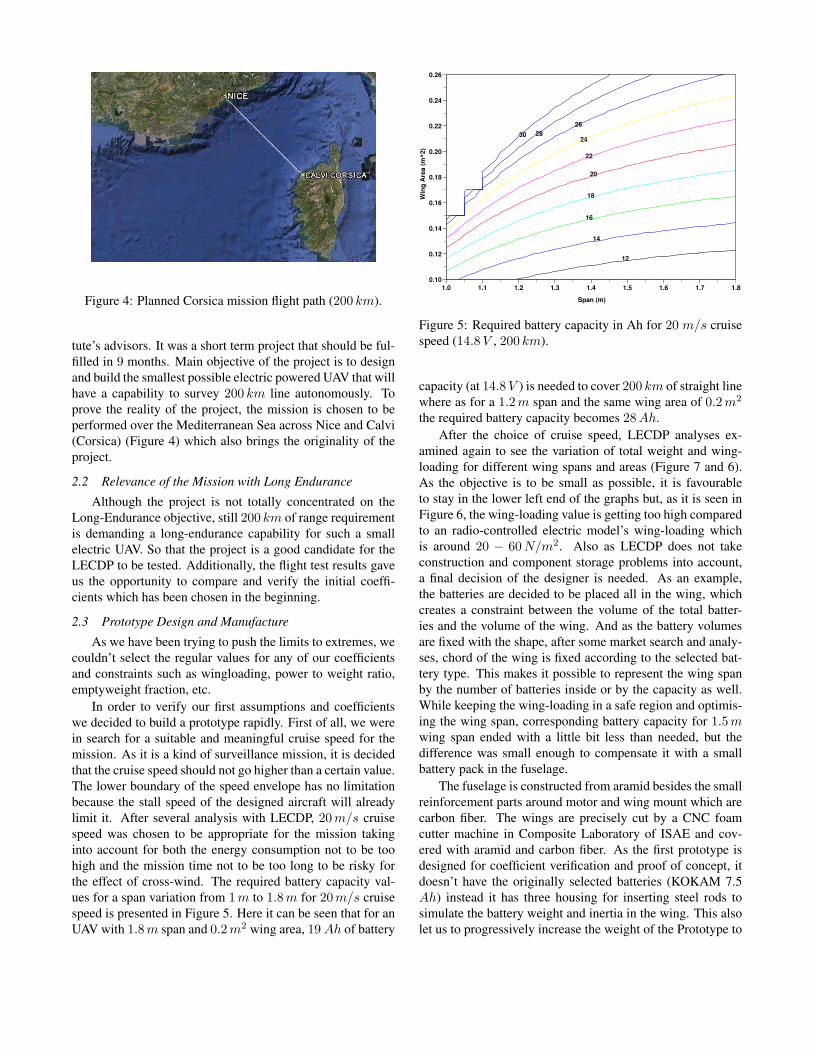
Figure 4: Planned Corsica mission flight path (200 km).
tute’s advisors. It was a short term project that should be ful-filled in 9 months. Main objective of the project is to designand build the smallest possible electric powered UAV that willhave a capability to survey 200 km line autonomously. Toprove the reality of the project, the mission is chosen to beperformed over the Mediterranean Sea across Nice and Calvi(Corsica) (Figure 4) which also brings the originality of theproject.
2.2 Relevance of the Mission with Long Endurance
Although the project is not totally concentrated on theLong-Endurance objective, still 200 km of range requirementis demanding a long-endurance capability for such a smallelectric UAV. So that the project is a good candidate for theLECDP to be tested. Additionally, the flight test results gaveus the opportunity to compare and verify the initial coeffi-cients which has been chosen in the beginning.
2.3 Prototype Design and Manufacture
As we have been trying to push the limits to extremes, wecouldn’t select the regular values for any of our coefficientsand constraints such as wingloading, power to weight ratio,emptyweight fraction, etc.
In order to verify our first assumptions and coefficientswe decided to build a prototype rapidly. First of all, we werein search for a suitable and meaningful cruise speed for themission. As it is a kind of surveillance mission, it is decidedthat the cruise speed should not go higher than a certain value.The lower boundary of the speed envelope has no limitationbecause the stall speed of the designed aircraft will alreadylimit it. After several analysis with LECDP, 20 m/s cruisespeed was chosen to be appropriate for the mission takinginto account for both the energy consumption not to be toohigh and the mission time not to be too long to be risky forthe effect of cross-wind. The required battery capacity val-ues for a span variation from 1 m to 1.8 m for 20 m/s cruisespeed is presented in Figure 5. Here it can be seen that for anUAV with 1.8 m span and 0.2 m2 wing area, 19 Ah of battery
12
14
16
18
20
22
24
26
28 30
1.0 1.1 1.2 1.3 1.4 1.5 1.6 1.7 1.8
0.10
0.12
0.14
0.16
0.18
0.20
0.22
0.24
0.26
Span (m)
Win
g A
rea
(m
^2
)
Figure 5: Required battery capacity in Ah for 20 m/s cruisespeed (14.8 V , 200 km).
capacity (at 14.8 V ) is needed to cover 200 km of straight linewhere as for a 1.2 m span and the same wing area of 0.2 m2
the required battery capacity becomes 28 Ah.After the choice of cruise speed, LECDP analyses ex-
amined again to see the variation of total weight and wing-loading for different wing spans and areas (Figure 7 and 6).As the objective is to be small as possible, it is favourableto stay in the lower left end of the graphs but, as it is seen inFigure 6, the wing-loading value is getting too high comparedto an radio-controlled electric model’s wing-loading whichis around 20 − 60 N/m2. Also as LECDP does not takeconstruction and component storage problems into account,a final decision of the designer is needed. As an example,the batteries are decided to be placed all in the wing, whichcreates a constraint between the volume of the total batter-ies and the volume of the wing. And as the battery volumesare fixed with the shape, after some market search and analy-ses, chord of the wing is fixed according to the selected bat-tery type. This makes it possible to represent the wing spanby the number of batteries inside or by the capacity as well.While keeping the wing-loading in a safe region and optimis-ing the wing span, corresponding battery capacity for 1.5 mwing span ended with a little bit less than needed, but thedifference was small enough to compensate it with a smallbattery pack in the fuselage.
The fuselage is constructed from aramid besides the smallreinforcement parts around motor and wing mount which arecarbon fiber. The wings are precisely cut by a CNC foamcutter machine in Composite Laboratory of ISAE and cov-ered with aramid and carbon fiber. As the first prototype isdesigned for coefficient verification and proof of concept, itdoesn’t have the originally selected batteries (KOKAM 7.5Ah) instead it has three housing for inserting steel rods tosimulate the battery weight and inertia in the wing. This alsolet us to progressively increase the weight of the Prototype to

120
125
130
135 140
145
150
155 160
1.1 1.2 1.3 1.4 1.5 1.6 1.7 1.8
0.10
0.12
0.14
0.16
0.18
0.20
0.22
0.24
0.26
Span (m)
Win
g A
rea
(m
^2
)
Figure 6: Wing-loading (N/m2) at 20 m/s cruise speed.
16
18
20
22
24
26
28
30 32
34
1.0 1.1 1.2 1.3 1.4 1.5 1.6 1.7 1.8
0.10
0.12
0.14
0.16
0.18
0.20
0.22
0.24
0.26
Span (m)
Win
g A
rea
(m
^2
)
Figure 7: Total weight (N ) at 20 m/s cruise speed.
PrototypeRequired Total Power (W ) 126.44
Battery Capacity (Ah) 25.94Structural Weight (N) 5.35
Total Weight (N) 29.45Wing-Loading (N/m2) 124.28
Lift Coefficient 0.5072Span (m) 1.5
Chord (m) 0.158Drag (N) 2.36
Table 2: Chosen values for the first prototype from theLECDP results.
Figure 8: Sketch of the prototype with its components.
Figure 9: Prototype ready for its first flight.
Figure 10: Surface quality and holes for steel rods simulatingbattery weight and inertia.

measure its flying characteristics and also power consumptionfor different weights.
2.4 Propulsion and Flight TestsThe prototype’s wing design lets to be tested for differ-
ent weights. First to measure the flight characteristics of theplane, only carbon rods are inserted for joining the two wing-halves and as a result the first flights were made for only 1kgof total mass. At this weight, it was satisfactory enough tohand-launch the plane. After tuning the manual and autopilotsettings, steel rods were inserted for progressively increasingthe weight up to expected flying weight.
In order to obtain aerodynamic and propulsion efficien-cies from the flight tests, two methods are planned. First isto climb at a safe altitude, glide along a straight line with-out throttle at a certain velocity to obtain the lift to drag ratioof the whole plane [12, 13]. Lacking of a differential pres-sure sensor for speed measurements and just being relyingon GPS information for speed and altitude, environmental ef-fects such as thermals and sinks, made it not possible to havesatisfactory results in a short term glide tests. So it is moreconcentrated on a long term test which will give better val-ues when averaged. In Figure 11, which is the view of theflight test trajectories exported to Google Earth, fixed altitudecircle and oval type flights can be seen. On those flights, al-titude and cruise speed tried to be kept fixed and circles areflown for 160 seconds autonomously. Power consumptionis also recorded. After averaging, it is seen that the cruisespeed is 18.6 m/s instead of 20 m/s, which also effects thepredicted design power consumption. Table 3 shows the pre-viously designed values, the values obtained from flight testsand the updated values as the cruise speed changes betweenthe designed conditions and the flight conditions. It can beeasily seen that the first coefficient assumptions were overlypessimistic.
Figure 11: First autonomous flight test
After modifying the coefficients according to the obtainedresults from flight tests, it was obvious that the size of theplane can be decreased a little bit, but unfortunately the se-lected batteries can only allow a major difference as the pack
Designed Flight UpdatedTotal Power (W ) 126.44 63.5 100.8
Cruise Speed (m/s) 20 18.6 18.6Battery Volts (V ) 14.4 13.35 14.4
Table 3: Variation of Designed, Tested and Updated values.
sizes are fixed. However another option could be to changethe battery type and brand but as it is a short term project,there was not enough time to do that.
3 STUDY FOR A HYBRID SOLAR POWERED MAVAlthough having verified the coefficients with the flight
test of the prototype, the results that were obtained fromLECDP for MAVs were not consistent. So we used previ-ous flight data acquired from Slicer and Storm-1 10 and wind-tunnel results to recalibrate some of the coefficients in theLECDP for MAV scale. After this tuning, analyses were donefor the hybrid system with the solar energy and Li-Po batterytaken into account. The objective was to see the feasibility ofusing solar energy for MAVs to enhance the flight time.
Two different configuration were taken into account,500 mm and 300 mm span. For each of the configurations,wing area and endurance have been optimised using LECDPfor a given battery capacity on board (910 mAh).
In the analyses, the maximum sun irradiance is taken as900 W/m2 and 70 % of the wing is assumed to be coveredwith solar cells. The efficiency of the solar cells, 16.9 %, istaken as it is given in the data sheet of the manufacturer.
Figure 12 shows the flight time versus the cruise speedof two different configurations with and without solar cells.Both have the same battery capacity on board. It can be seenthat the benefit that is taken from solar cells for flight timeis much higher for the bigger 500 mm MAV than the small300 mm one. It can be shown that under a certain size, thereis almost no benefit that can be taken from the solar cells.This is a result of the reduced wing surface area of the smallsized MAV reducing the total solar cell area which is linearlyproportional with energy extracted from sun. Another impor-tant issue is the weight ratio of the solar cells and the requiredelectronics to the weight of the MAV. This ratio is becominglarger when the MAV gets smaller in size, then reducing theoverall efficiency of the MAV. It should be noted that theseconclusions are made taking into account the Paparazzi au-topilot and electronics weights.
Figure 13 shows the hybrid solar powered MAV proto-type. Twenty RWE Si-32 solar cells are bonded on the wingwith silicon based glue11. The wing platform is optimisedin order to place the maximum number of solar cells safelyon the surface while keeping in mind the span efficiency, el-liptical loading and the tip stall issues. This was especially
10Previous MAVs that were designed and flew in competitions by our team11With the collaboration of the www.map-coatings.com/ company

10 11 12 13 14 15 16 17 18
0
20
40
60
80
100
120
Cruise Speed (m/s)
En
du
ran
ce
(m
in)
500mmLiPo+Solar
500mmLiPo
300mmLiPo+Solar
300mmLiPo
Figure 12: Endurance comparison of 500mm and 300mmMAVs using solar cells.
important in order to reach the same percentage of solar cellarea to wing area that we have assumed in the calculations.
The powerful XFOIL airfoil analysis and design programis used to design the airfoils. There are three different cus-tom airfoils along the span, which are particularly designedaccording to their corresponding Reynolds number for thecruise speed while observing the stall behaviour and maxi-mum lift coefficient. Spanwise transition and the design pro-cedure will not be included here more deeply as it is not inthe scope of this paper.
Figure 13: Solar-Storm prototype
3.1 Maximum Power Point TrackerAlthough we have kept the efficiency of the solar cells
constant and at maximum value (16.9 %) in the calculations,this is not exactly true for all cases in real life.
According to the angle of the solar cells with the sun rays,time of the day and year, geographic location, solar cells willhave different output power.
Figure 14: MPPT for solar cells.
When the pads of the solar cells are not connected, thevoltage between the pads is VOC the open circuit voltage andthe current is null. When the pads are short circuited, thevoltage becomes zero and the current is ISC , the short circuitcurrent. The maximum output power has to be found betweenthese two points. This point is called maximum power point(MPP ) and the voltage and the current at this particular pointare VMPP and IMPP .
The search for the MPP requires an ad hoc electronicscircuitry adapted in real time with a control loop. Figure 14shows the schematics of this board. Note that it includes amicro-controller which can be linked to the autopilot to bemonitored from the ground station.
4 CANDIDATE DESIGN FOR EMAV09 ENDURANCEMISSION
4.1 Mission Definition
EMAV09 Outdoor Endurance Mission simulates a pay-load drop task where the target is far away from the launchzone. The distance between the launch zone and the target issimulated by flying a number of laps to the target, dropping apaintball on the target and then returning by flying the samenumber of laps before landing.
Although it has been shown in the previous sections re-sults that a 300 mm MAV will not be able to achieve flighttimes as long as a 500 mm MAV does, still the rules ofEMAV09 Endurance Mission promote being small by takinginto account maximum dimension at the fligth score calcula-tion.
However, the mission is more focused on the range per-formance rather than the maximum airborne time. So, itis more important to fly at the ”maximum lift to drag ratiospeed” of the MAV rather than the ”minimum power con-sumption speed” in order to get more points.
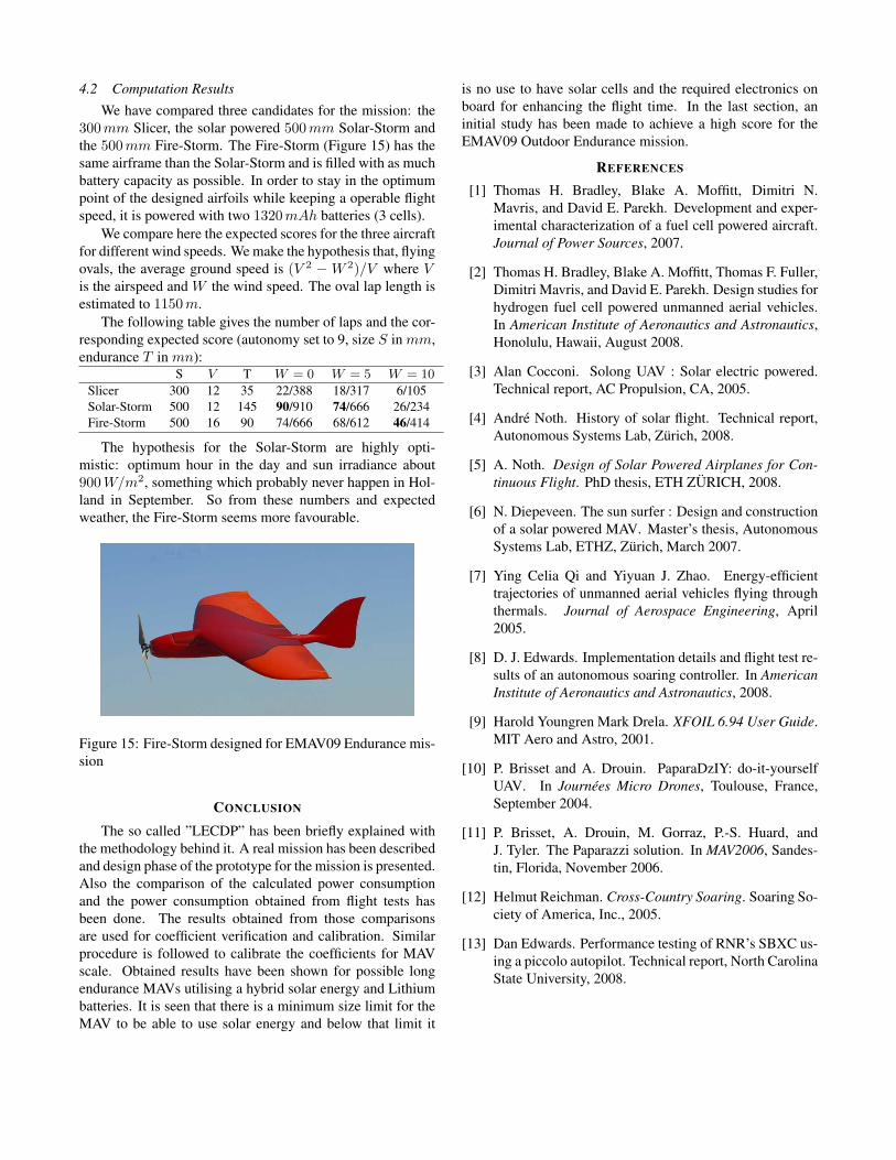
4.2 Computation ResultsWe have compared three candidates for the mission: the
300 mm Slicer, the solar powered 500 mm Solar-Storm andthe 500 mm Fire-Storm. The Fire-Storm (Figure 15) has thesame airframe than the Solar-Storm and is filled with as muchbattery capacity as possible. In order to stay in the optimumpoint of the designed airfoils while keeping a operable flightspeed, it is powered with two 1320 mAh batteries (3 cells).
We compare here the expected scores for the three aircraftfor different wind speeds. We make the hypothesis that, flyingovals, the average ground speed is (V 2 −W 2)/V where Vis the airspeed and W the wind speed. The oval lap length isestimated to 1150 m.
The following table gives the number of laps and the cor-responding expected score (autonomy set to 9, size S in mm,endurance T in mn):
S V T W = 0 W = 5 W = 10
Slicer 300 12 35 22/388 18/317 6/105Solar-Storm 500 12 145 90/910 74/666 26/234Fire-Storm 500 16 90 74/666 68/612 46/414
The hypothesis for the Solar-Storm are highly opti-mistic: optimum hour in the day and sun irradiance about900 W/m2, something which probably never happen in Hol-land in September. So from these numbers and expectedweather, the Fire-Storm seems more favourable.
Figure 15: Fire-Storm designed for EMAV09 Endurance mis-sion
CONCLUSION
The so called ”LECDP” has been briefly explained withthe methodology behind it. A real mission has been describedand design phase of the prototype for the mission is presented.Also the comparison of the calculated power consumptionand the power consumption obtained from flight tests hasbeen done. The results obtained from those comparisonsare used for coefficient verification and calibration. Similarprocedure is followed to calibrate the coefficients for MAVscale. Obtained results have been shown for possible longendurance MAVs utilising a hybrid solar energy and Lithiumbatteries. It is seen that there is a minimum size limit for theMAV to be able to use solar energy and below that limit it
is no use to have solar cells and the required electronics onboard for enhancing the flight time. In the last section, aninitial study has been made to achieve a high score for theEMAV09 Outdoor Endurance mission.
REFERENCES
[1] Thomas H. Bradley, Blake A. Moffitt, Dimitri N.Mavris, and David E. Parekh. Development and exper-imental characterization of a fuel cell powered aircraft.Journal of Power Sources, 2007.
[2] Thomas H. Bradley, Blake A. Moffitt, Thomas F. Fuller,Dimitri Mavris, and David E. Parekh. Design studies forhydrogen fuel cell powered unmanned aerial vehicles.In American Institute of Aeronautics and Astronautics,Honolulu, Hawaii, August 2008.
[3] Alan Cocconi. Solong UAV : Solar electric powered.Technical report, AC Propulsion, CA, 2005.
[4] Andre Noth. History of solar flight. Technical report,Autonomous Systems Lab, Zurich, 2008.
[5] A. Noth. Design of Solar Powered Airplanes for Con-tinuous Flight. PhD thesis, ETH ZURICH, 2008.
[6] N. Diepeveen. The sun surfer : Design and constructionof a solar powered MAV. Master’s thesis, AutonomousSystems Lab, ETHZ, Zurich, March 2007.
[7] Ying Celia Qi and Yiyuan J. Zhao. Energy-efficienttrajectories of unmanned aerial vehicles flying throughthermals. Journal of Aerospace Engineering, April2005.
[8] D. J. Edwards. Implementation details and flight test re-sults of an autonomous soaring controller. In AmericanInstitute of Aeronautics and Astronautics, 2008.
[9] Harold Youngren Mark Drela. XFOIL 6.94 User Guide.MIT Aero and Astro, 2001.
[10] P. Brisset and A. Drouin. PaparaDzIY: do-it-yourselfUAV. In Journees Micro Drones, Toulouse, France,September 2004.
[11] P. Brisset, A. Drouin, M. Gorraz, P.-S. Huard, andJ. Tyler. The Paparazzi solution. In MAV2006, Sandes-tin, Florida, November 2006.
[12] Helmut Reichman. Cross-Country Soaring. Soaring So-ciety of America, Inc., 2005.
[13] Dan Edwards. Performance testing of RNR’s SBXC us-ing a piccolo autopilot. Technical report, North CarolinaState University, 2008.