Spiritually Motivated Natural Resources Protection in Eastern Bhutan

Encyclopedia of Aerospace Engineering, Online © 2010 John Wiley & Sons, Ltd.This article is © 2010 John Wiley & Sons, Ltd.This article was published in the Encyclopedia of Aerospace Engineering in 2010 by John Wiley & Sons, Ltd.
MAV-Motivated Structures and Materials
Kwang-Joon Yoon, Joon-Hyuk Park, and Sriyulianti WidhiariniKonkuk University, Seoul, Korea
1 Introduction 1
2 Flapping-wing MAV Development 1
3 Design and Manufacture of BiomimeticFlapping-wing MAV 4
4 Performance Test and Evaluation 8
5 Summary 11
Acknowledgments 11
References 11
1 INTRODUCTION
Nature’s flyers, such as birds, bats, and insects have amazedhumankind for long with their remarkable flight charac-teristics, which triggered the development of manmade airvehicles. The study of flight can be traced back to the earliestdesign of the manmade flying machine, by Leonardo da Vinciin 1500s in the form a of flapping vehicle. However, the devel-opment drifted ever since the successful powered flight usingfixed-wings by Wright brothers. More remarkable innova-tions later followed this success, and they were all focusedon fixed wing aircraft.
Recently, active air vehicle research, inspired by nature’sflyers, has led to the development of micro air vehicles(MAVs). It is now a well-integrated research area in the devel-opment of smaller flight vehicles for environmental monitor-ing, surveillance, and assessments in hostile environments.As the sizes of the MAVs are getting smaller, they have been
developed to mimic nature as closely as possible. They areexpected to have high maneuverability and very low speed ca-pability, but at the same time, should be able to reach those ca-pabilities with high power and high aerodynamic efficiency ina low Reynolds number environment, from 50 000 to 150 000.Consequently, MAVs will experience increasing drag andloss of efficiency due to the low Reynolds number. Due tothe limitations of size, their wings also have a small aspectratio which will reduce the effective angle of attack andinduce the 3D flow structure created when they fly. Moreover,they are also sensitive to wind gusts, and become moredifficult to control.
MAVs can be generally categorized into three kinds basedon their mechanism of producing lift: fixed, rotary, andflapping-wing. Research on fixed-wing MAV is the most de-veloped area among other categories. The second category ofMAV is rotary-wing. Compared to the earlier type, this MAVhas a relatively lower endurance due to its smallscale rotorscausing highly effective power requirements for the hover.Next is the flapping-wing MAV, its research comes fromthe inspiration of mimicking the mechanism and features ofbirds and insects. The aerodynamics of this vehicle is highlyunsteady due to acceleration and deceleration of the wing dur-ing its up and down movements, in addition to the highly rela-tive viscous effect at low Reynolds number that already exists.
2 FLAPPING-WING MAVDEVELOPMENT
2.1 Overview
MAVs with a 15 cm wingspan seem to have the characteristicsbetween the borders of two groups of nature’s flyers because
DOI: 10.1002/9780470686652.eae405

Encyclopedia of Aerospace Engineering, Online © 2010 John Wiley & Sons, Ltd.This article is © 2010 John Wiley & Sons, Ltd.This article was published in the Encyclopedia of Aerospace Engineering in 2010 by John Wiley & Sons, Ltd.
2 Micro Air Vehicles
Figure 1. Size of natural flyers. Reproduced from Pornsin-Siriraket al. (2000) c© IEEE.
it lies between these two groups as shown in Figure 1. Smallerflyers, like insects and hummingbirds are able to hover yetthey cannot soar. On the other hand, bigger flyers like birdsand bats cannot hover but they can soar. The small-size flyersuse the flapping-wing mechanism to generate lift to overcometheir own weight.
Related to the development of MAV, the smaller the size ofthe vehicle, the more it resembles the features of the nature’sflyers, in this case, large insects. Then, it will be more effi-cient to apply the flapping mechanism for this type of vehiclecompared to using the fixed-wing. The airfoil performance ofa fixed-wing MAV will reduce severely for Reynolds numberin this range. Since a lower lift coefficient will be obtained, thewings will have lower loading capability. Moreover, due tothe higher drag coefficient resulting from the viscosity, higherpower input is necessary. Flow separation on the wing, whichcauses stall at low angles of attack, will also reduce the per-formance and maneuverability of the wings (Pornsin-Siriraket al., 2000). These reasons have encouraged more researchon flapping-wing mechanism to emerge.
One of the earliest developments of flapping-wing MAVwas Aerovironment Microbat, a palm-sized 10 g ornithopter,capable of flying around for 5 minutes (Pornsin-Siriraket al.,2000). Several research teams from different universitiesalso took part in the development of flapping-wing MAVs.University of Arizona has been developing ornithopter since2000, with its noticeable design, a 15-inch wingspan, and47 g RC ornithopter (Olsonet al., 2005). TU Delft cre-ated Delfly, inspired by the flight of a dragonfly, capableof performing a straight and horizontal flight and transformto a very slow, hovering flight (http://www.delfly.nl/?site=DIII%26menu=home%26lang=en). MAV research teamin Konkuk University, Korea has also been developing
flapping-wing MAVs, since 2002 for the participation in In-ternational Micro Air Vehicle Competition (IMAVC) andEuropean Micro Air Vehicle (EMAV) competition.
IMAV and EMAV flight competitions are two major MAVcompetitions. The IMAVC consists of three major cate-gories: (i) Ornithopter competition of the smallest radio-controlled ornithopter, (ii) Surveillance, and (iii) Endurance.On the other hand, EMAV competition is divided into indoorand outdoor competitions, each section comprising flightdynamics and autonomy categories.
Recent studies on MAVs cover various fields, fromaerodynamics to navigation and control. In aerodynam-ics, the studies have been conducted to reveal the secretsbehind the flight mechanisms of both birds and insects. Theflight of birds is characterized by the capability of soar-ing and gliding, whereas insects are more toward hovering.Research conducted to analyze the unsteady flight mecha-nism can be characterized into four categories: rotation cir-culation (Dickinson, Lehman, and Sane, 1999), clap and fling(Weis-Fogh, 1973), wake capture (Dickinson, Lehman, andSane, 1999), added mass (Ellington, 1984), and leading edgevortex (Ellingtonet al., 1996). Each mechanism will be re-lated to the performance of the main aerodynamic and powersource, particularly the wings. Hence, the development ofstructural design of the wings becomes necessary.
The on-going researches of flapping-wing MAVs are be-ing focused on reducing the size of the vehicle as a way tomimic the natural flyers closely. Therefore, the developmentand optimization of the structural design of the vehicle arenecessary. One important breakthrough is the minimizationof the weight of the MAV by using composite material forthe vehicle structure. The use of these advanced materials isexpected to reduce the weight of the MAV without signifi-cantly affecting the flight performance of the vehicle. There-fore, more studies on lightweight composite structures arebeing conducted to demonstrate the possibility.
Due to the fast response of direct and reverse piezoelec-tric effects, more research studies have also been conductedto cover the needs of a high-density power source to re-place the motor. Piezoelectric materials are promising can-didates for this. One of the most significant works of insect-mimicking MAV design was made at the University of Cal-ifornia at Berkeley (Fearinget al., 2000). A micromechan-ical flying insect (MFI) actuated by two unimorph piezo-electric actuators produced a flapping angle of 80◦ at flap-ping frequency of 275 Hz and average lift of 1400�N froma single wing, including the inertia force (Sitti, 2001; Steltz,Avadhanula and Fearing, 2007). Konkuk University has alsosuccessfully demonstrated a flapping device actuated by aunimorph actuator which can passively create wing rotationand produce a 2.7 g vertical force and a 0.83 g forward force
DOI: 10.1002/9780470686652.eae405

Encyclopedia of Aerospace Engineering, Online © 2010 John Wiley & Sons, Ltd.This article is © 2010 John Wiley & Sons, Ltd.This article was published in the Encyclopedia of Aerospace Engineering in 2010 by John Wiley & Sons, Ltd.
MAV-Motivated Structures and Materials3
at a driven peak-to-peak voltage of 300 Vpp and a flappingfrequency of 9 Hz (Parket al., 2004; Syaifuddin, Park andGoo, 2006; Nguyenet al., 2007). The latest development is a60 mg flapping-wing system introduced by Harvard Univer-sity which was actuated by a small unimorph piezoelectric ac-tuator (Wood, 2007). However, even the latest breakthroughin the use of piezoelectric actuator still cannot offer an inde-pendent flight system. Therefore, embedding a lightweightsystem in a part of the vehicle is also necessary, so that mini-mization of the weight will be more effective. The structuralsystem of the wing as the main part of the MAV also needsparticular attention. By modifying the shape and structuralsystem to be similar to that of the biological counterparts,the vehicle is expected to be lighter yet have a good flightperformance for a flight-capable flapping-wing MAV.
2.2 KU flapping-wing MAV development
With the aim to create an RC-controllable flapping-wingMAV, the MAV research team in Konkuk University has beendeveloping different kinds of MAVs. The development ofthose vehicles was first started to find out the best design ofMAV for the IMAVC. However, in the long run, the studywas also diversified to analyze the biomimetic structure offlapping-wing inspired by birds and insects, to be applied tothe design of a flight-capable MAV. This is motivated by thefact that the study for the wing structure of a flight-capableflapping-wing MAV has not been specifically conducted inany other research.
Figure 2 shows the shape of KU-Ornithopter with a 28 cmwingspan developed in 2006. It could fly for more than 8minutes by a remote-control at 2–3 m s−1 wind condition.It was the primitive development of the flapping-wing vehi-cle, and its wing was not particularly designed to follow anyspecific biological insect or bird. Instead, it only focused onkeeping stiff leading edge and flexibility at the rest of the
wing. The vehicle was designed to complete the mission inthe 2006 International Micro Air Vehicles Competition. Themission was to fly 8 or O shaped turns between two poles12 m distance apart, as many times as possible in a limitedtime period to get a high score. Since sharp and rapid turningswere needed, the focus was also on producing high maneu-verability. It was ranked 2nd for the ornithopter mission atthe 10th IMAVC in 2006.
Since then, the development of KU-Ornithopter hascontinued. Many studies and experiments were conductedto enhance the flight performance of the vehicle. Figure 3shows the 36 cm flapping wing ornithopter developed in 2007with an onboard micro-video camera. The tail structure of theearliest development was still maintained, however it wasmodified by a rudder and elevator to enhance the control ofthe vehicle.
For out-of-sight control and guidance, the micro-videocamera was mounted at the front nose of the MAV with atransmitter in order to collect the vision images and send itto the ground station. It was placed pointing to the ground30◦ downward from the flight direction, which intended tocapture the ground images during the level flight. Althoughsome fuzzy and vibrating images were received due to the vi-bration from flapping motion, it could transmit the pilot viewreal-time video image within 200 m remote control range,which enables vision/image-based control. The landing gearsystem was employed in the MAV for takeoff and landingat flat ground less than 20 m without hand-launching assis-tance. Three wheels were attached to the fuselage with 22◦
incidence angle from the horizontal plane. The indoor flightdemonstration for this vehicle was successfully performed atthe MAV07 in Toulouse, France in 2007.
Besides enhancing the vehicle’s flight performance for thecompletion of IMAVC and EMAV flight missions, the devel-opment was also made to the wing structure of the vehicle.The 36 cm flapping-wing MAV was modified by mimickingthe structure of nature’s flyers. This study was carried out to
Figure 2. KU-Ornithopter-06 with 28 cm wingspan and 1st prototype composite wing structure.
DOI: 10.1002/9780470686652.eae405

Encyclopedia of Aerospace Engineering, Online © 2010 John Wiley & Sons, Ltd.This article is © 2010 John Wiley & Sons, Ltd.This article was published in the Encyclopedia of Aerospace Engineering in 2010 by John Wiley & Sons, Ltd.
4 Micro Air Vehicles
Figure 3. KU-Ornithopter-07 with 36 cm wingspan, biomimetic wing structure, and onboard camera.
Figure 4. 15 cm KU-Ornithopter-08 with biomimetic wing structure.
analyze the significance of biomimetic structure to the flightefficiency. The wing of Cicada (Cicadidae) was chosen as thebase for the artificial wing development. The main featuresof Cicada were applied to the wings, such as the camber wingin spanwise direction, thickness difference through wing rootto wing tip, and a cell-type wing structure. More details willbe given in the following section.
The development of the flapping wing vehicle contin-ued further to reduce the size of the vehicle with an im-proved design. In 2008, the 15 cm KU-Ornithopter was devel-oped. Some changes were made to the altitude control, whichchanged the flapping frequency by controlling the RPM ofthe motor and tail structure and by removing the horizontalstabilizer, as shown in Figure 4. The total force generated bythe wing was not sufficient to fly under wind velocity over2 m s−1, so most of the flight tests were conducted indoor. Itwas ranked 3rd in the indoor dynamic mission category atthe EMAV flight competition in 2008 held at Braunschweig,Germany.
3 DESIGN AND MANUFACTURE OFBIOMIMETIC FLAPPING-WING MAV
3.1 Biomimetic wing development
Wings play the most important role in flapping wing flightnot only to change the direction of the movement, but also toundergo deformation, which may lead to aerodynamic forcegeneration during the flight. More specifically, there is noinsect that flies by using only the simple flexural vibrationof the wings. Insects are able to fly only through complexflight mechanisms, such as delayed stall, rotational circula-tion, and wake capture. However, there is no report on a devel-oped artificial flapping mechanism which can perform thosemechanisms at the same time. Modifying the wing structureof a flapping-wing vehicle to resemble closely that of thenature’s flyers, thus became the focus of this research. Toprove that such a modification will affect flight efficiency,the biomimetic structure was applied to the vehicle and some
DOI: 10.1002/9780470686652.eae405

Encyclopedia of Aerospace Engineering, Online © 2010 John Wiley & Sons, Ltd.This article is © 2010 John Wiley & Sons, Ltd.This article was published in the Encyclopedia of Aerospace Engineering in 2010 by John Wiley & Sons, Ltd.
MAV-Motivated Structures and Materials5
Figure 5. Wing shape and structure of Cicada.
simplifications were made during the fabrication by main-taining the main features of the insect’s wing.
By analyzing the wings of Cicada, three main featuresof its wings were identified: camber in chord and span-wisedirection, thickness difference throughout the wing root towing tip, and cell-type membranes. These features are shownin Figure 5. Camber in chord and span-wise directions isimportant to efficiently control the wing deformation duringthe flapping motion. The cell-type membrane was a resultof the wing vein structure throughout the whole wing areaand the vein thickness variation, which stiffens the insect’swings. By keeping these main features, the artificial wing wascreated with modifications.
The thickness variation occurs as a result of the veins,which surrounds the cell membranes; thickness is reducedfrom the wing root to the wing tip. These features showedthat the insect wing has an efficient wing structure for un-steady flight (Park and Yoon, 2008). Moreover, camber onboth spanwise and chord directions are also important to effi-ciently control the wing deformation during flapping motion.Keeping these features of insect wing in mind, attempts weremade to mimic the insect features.
The biomimetic wing development was done initially byadding more frames to the original structure and adoptingcamber in the spanwise direction. In order to compare the
Table 1. Dimension and properties of materials.
Thickness WidthMaterial Part (mm) (mm)
Carbon/epoxy Wing frame 1 (6 layers) 1.2 2fabric frame Wing frame 2 (4 layers) 0.8 2
E1 = 59.1 GPa;E2 = 55.7 GPa;G12 = 4.7 GPa;
�12 = 0.06
Carbon/Epoxy Diameter (mm) 1.2
Rod E1 = 100 GPa;E2 = 7.0 GPa;G12 = 4.0 GPa;�12 = 0.3
PET Film Thickness (mm) 0.02
E = 1.8 GPa;�12 = 0.3
flight characteristics between the artificial and normal wings,we set two types of wings for the experiment. Both wingswere composed of carbon/epoxy frame for the main sparand polyethylene terephthalate (PET) for the wing skin. Thedimension and properties of these materials are shown inTable 1. Type A, the 1st prototype wing design is a flat wingwith one frame placed across the wing area as shown inFigure 6a. Type B, the biomimetic wing, is a cambered wing
Figure 6. Wing structure and materials: (a) 1st prototype wing and (b) biomimetic wing. Reproduced from Park and Yoon (2009)c©Springer.
DOI: 10.1002/9780470686652.eae405

Encyclopedia of Aerospace Engineering, Online © 2010 John Wiley & Sons, Ltd.This article is © 2010 John Wiley & Sons, Ltd.This article was published in the Encyclopedia of Aerospace Engineering in 2010 by John Wiley & Sons, Ltd.
6 Micro Air Vehicles
Figure 7. Airfoil EH3012 (modified).
along its chord direction divided into many cells by a numberof frames. To increase the stiffness through the wingspandirection, additional carbon/epoxy fabric frame were addedto the main spar, as shown in Figure 6b.
The thin cambered airfoil similar to that of Cicada wasselected to adjust the low Reynolds number environment andminimize the drag resulting from the flight. By using theX-foil software, the EH3012 airfoil was cut from the leadingedge by 7.7% and only the airfoil with the upper surface wasdesigned, as shown in Figure 7.
A steel mold for the cambered wing frame fabricationbased on a previous design, was prepared. The manufactur-ing procedure is summarized in Figure 8. To begin with, thecarbon/epoxy prepregs were placed on the cambered mold.Then the mold and wing structure were vacuum-bagged tobe cured later in an autoclave at 125◦C. After curing, PETwas attached to the frame using cyanoacrylate adhesive toperfectly bond the frame and skin.
Figure 8. Typical manufacturing process of wing composite fabrication. Reproduced from Park and Yoon (2009)c© Springer.
3.2 Fuselage structure development
Many attempts have been made for the development of ef-ficient fuselage shape and material structure of the KonkukUniversity’s flapping-wing MAV. There were four types ofstructures with different materials ranging from balsa woodto composite structure. The structure of the MAV should bestrong enough to withstand hard-landing, stiff enough for theplacement of the components but at the same time it shouldalso be lightweight. A lightweight material should be chosenfor the structure, since the weight issue will also determinethe performance of the MAV flight.
First, balsa plate was used for the fuselage to place theelectronic components. This type of wood is well known tothe airplane hobbyist, as the best material to construct modelairplane owing its high strength and low density characteris-tics. It can also be easily shaped, glued, and painted. However,due to small balsa thickness it is weak; as a result, on impactit was easily broken into pieces or split in the middle duringhard-landing as shown in Figure 9a.
Next, in order to prevent the damage in landing, car-bon/epoxy plate was used, as shown in Figure 9(b). Carbon/epoxy plate has good characteristics to withstand tensileand compressive strengths in longitudinal and transverse
DOI: 10.1002/9780470686652.eae405

Encyclopedia of Aerospace Engineering, Online © 2010 John Wiley & Sons, Ltd.This article is © 2010 John Wiley & Sons, Ltd.This article was published in the Encyclopedia of Aerospace Engineering in 2010 by John Wiley & Sons, Ltd.
MAV-Motivated Structures and Materials7
Figure 9. Fuselage structure and materials: (a) balsa plate, (b) carbon/epoxy plate without cut-out, (c) carbon/epoxy rod frame, and(d) PET plate and carbon/epoxy rod.
directions. Thus, the damage decreased remarkably whenthe vehicle experienced hard-landing. Since the structure hadmuch heavier weight compared to balsa, the overall MAVweight increased, affecting the flight performance of thesystem.
We then decided to build the mainframe solely withcarbon/epoxy rods, as shown in Figure 9c. This idea was
effective in solving the weight issues. Nevertheless, placingall the entire components on the mainframe was more diffi-cult. The components could not be placed firmly at a certainposition, so their positions during the flight were very muchaffected. Moreover, the damage was not entirely solved sincethe structure was still fragile for hard-landing. Thin PET platewas then added to the carbon/epoxy rod structure to provide
Figure 10. Glass/epoxy fuselage: (a) cut-out shape of glass/epoxy plate parts and (b) assembled fuselage structure.
DOI: 10.1002/9780470686652.eae405
Encyclopedia of Aerospace Engineering, Online © 2010 John Wiley & Sons, Ltd.This article is © 2010 John Wiley & Sons, Ltd.This article was published in the Encyclopedia of Aerospace Engineering in 2010 by John Wiley & Sons, Ltd.
8 Micro Air Vehicles
enough placement area, as shown in Figure 9d. However, itwas still ineffective to secure the components and no changeoccurred in its ability to withstand hard-landing.
The above-mentioned analyses of different structures andmaterials led to the design of a gearbox. The gearbox structureshould be light and stiff enough for the placement of thecomponents, as well as solving the issue of hard-landing. Forthis case, glass/epoxy plate was chosen as the material for thefuselage frame. CATIA® was used for designing the gearboxparts and CNC machine was used for cutting the structure, asshown in Figure 10a and b. The cut-out glass/epoxy plate wasproven to be the most appropriate fuselage component, whichprevents direct impact onto the electric component and wascompatible due to its lightweight even after several flight testswere conducted. Glass/epoxy was also used for the hinges.
4 PERFORMANCE TEST ANDEVALUATION
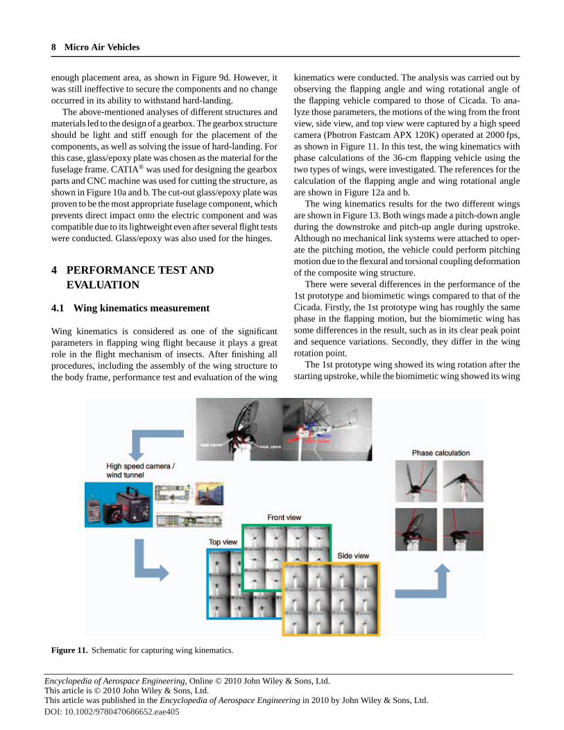
4.1 Wing kinematics measurement
Wing kinematics is considered as one of the significantparameters in flapping wing flight because it plays a greatrole in the flight mechanism of insects. After finishing allprocedures, including the assembly of the wing structure tothe body frame, performance test and evaluation of the wing
kinematics were conducted. The analysis was carried out byobserving the flapping angle and wing rotational angle ofthe flapping vehicle compared to those of Cicada. To ana-lyze those parameters, the motions of the wing from the frontview, side view, and top view were captured by a high speedcamera (Photron Fastcam APX 120K) operated at 2000 fps,as shown in Figure 11. In this test, the wing kinematics withphase calculations of the 36-cm flapping vehicle using thetwo types of wings, were investigated. The references for thecalculation of the flapping angle and wing rotational angleare shown in Figure 12a and b.
The wing kinematics results for the two different wingsare shown in Figure 13. Both wings made a pitch-down angleduring the downstroke and pitch-up angle during upstroke.Although no mechanical link systems were attached to oper-ate the pitching motion, the vehicle could perform pitchingmotion due to the flexural and torsional coupling deformationof the composite wing structure.
There were several differences in the performance of the1st prototype and biomimetic wings compared to that of theCicada. Firstly, the 1st prototype wing has roughly the samephase in the flapping motion, but the biomimetic wing hassome differences in the result, such as in its clear peak pointand sequence variations. Secondly, they differ in the wingrotation point.
The 1st prototype wing showed its wing rotation after thestarting upstroke, while the biomimetic wing showed its wing
Figure 11. Schematic for capturing wing kinematics.
DOI: 10.1002/9780470686652.eae405

Encyclopedia of Aerospace Engineering, Online © 2010 John Wiley & Sons, Ltd.This article is © 2010 John Wiley & Sons, Ltd.This article was published in the Encyclopedia of Aerospace Engineering in 2010 by John Wiley & Sons, Ltd.
MAV-Motivated Structures and Materials9
Upstroke (+)
Nose up (+)
Downstroke (−)
Nose down (−)
Reference axis
Reference axis
Flapping path
Body axis
(a) (b)
Figure 12. Definitions of (a) flapping angle and (b) pitching angle. Reproduced from Park and Yoon (2009)c© Springer.
Figure 13. Wing kinematics of the 1st prototype and biomimetic wings. Reproduced from Park and Yoon (2009)c© Springer.
rotation at the end of the downstroke. In other words, thebiomimetic wing had the point of wing rotation between thephase changing points of flapping, which is similar to that ofCicada. These findings proved that cambered and cell-typewing can perform better and similar to the Cicada comparedto the 1st prototype wing.
4.2 Aerodynamic force measurement
The aerodynamic force measurement for the two differentwings was conducted to observe the efficiency of applyingthe biomimetic wing structures of insects to the flappingvehicle. As mentioned earlier, the biomimetic wing has abetter performance in terms of its wing kinematics compared
to that of the 1st prototype wing. To assure that better effi-ciency does exist, force generation test wasalso performed(Figure 14).
Aerodynamic forces are the indispensable componentswhich support the flight. Most of the useful aerodynamicforce is generated in the middle of a downstroke duringthe flapping-flight. However, in this type of flapping mech-anism, the inertia force also plays an important role. Thistype of force is relatively large mostly at the end of upstrokeand downstroke, which contribute to the significance of thewing deformation effect. These phenomena may show thatthe contribution of the aerodynamic force due to the wingdeformation by the inertia force can be neglected within acycle.
DOI: 10.1002/9780470686652.eae405

Encyclopedia of Aerospace Engineering, Online © 2010 John Wiley & Sons, Ltd.This article is © 2010 John Wiley & Sons, Ltd.This article was published in the Encyclopedia of Aerospace Engineering in 2010 by John Wiley & Sons, Ltd.
10 Micro Air Vehicles
Figure 14. Force measuring system.
Therefore, the aerodynamic measurement was conductedby collecting the experimental data of the force measured inthe air and vacuum conditions as shown in Figure 15. Theaerodynamic force, then, can be calculated by subtractingthe inertia force, which is measured in the vacuum conditionfrom the total force. The experiment in the air condition wasconducted by preparing the two artificial wings to be testedunder the voltage 7.4 V. To adjust the flapping frequency andamplitude during the flight in the vacuum condition, the inputvoltage was adjusted such that the force calculated in the
vacuum condition can be regarded as the inertia force of thevehicle in the air.
Average aerodynamic lift produced by the 1st prototypewing was measured at the value of 0.075 N and thrust at thevalue of 0.018 N. While for the biomimetic wing, the aver-age aerodynamic lift and thrust were at 0.088 and 0.020 N,respectively. These results showed that both the lift and thrustgeneration of biomimetic wings are higher than those ofthe prototype wing, with 17% improvement in the lift forcegeneration and 11% improvement in the thrust generation.
Figure 15. Experiment setup for aerodynamic force measurement: (a) vacuum chamber flapping test system and (b) experimental setup.
DOI: 10.1002/9780470686652.eae405

Encyclopedia of Aerospace Engineering, Online © 2010 John Wiley & Sons, Ltd.This article is © 2010 John Wiley & Sons, Ltd.This article was published in the Encyclopedia of Aerospace Engineering in 2010 by John Wiley & Sons, Ltd.
MAV-Motivated Structures and Materials11
5 SUMMARY
Experimental investigations were performed to improve theflight performance of an ornithopter MAV and the aerody-namic forces and flight parameters of MAVs of the 1st proto-type wing were compared with those of the biomimetic wingstructure. Experimental verification showed that the lift andthrust generations could be increased by 11 and 17%, respec-tively, by replacing the 1st prototype wing by a biomimeticwing. This was our first effort to mimic the wing of a Cicada.Therefore, there seems to be sufficient scope to increase theperformance of the biomimetic wing.
For Reynolds number flight, particularly in the flapping-wing MAV development, insect-mimicking mechanism andstructures have proven to shed some light on creating an in-dependent flight system. Nevertheless, simplifications cannotbe avoided during its development. Moreover, creating an in-dependent flapping-wing MAV will require more effort interms of providing the lightest material and the most efficientmechanism that can fit into the small MAV structure.
The wing design based upon the coupling analysisof aerodynamic and structural mechanics may contributeto a great extent to the performance enhancement ofbiomimetic flapping-wing MAVs. Further developments ofthe biomimetic wing and an optimized system for ornithoptermay lead to a more sophisticated flapping–flying robot forsurveillance mission with stealth function, even smaller thanit is now.
ACKNOWLEDGMENTS
The authors would like to thank the Intensive ResearchCenter Program of Korea Research Foundation (KRF-2006-005-J03303) for financial support.
REFERENCES
Dickinson, M.H., Lehmann, F.O. and Sane, S.P. (1999) Wingrotation and the aerodynamics basis of insect flight.Science, 284,1954–1960.
Ellington, C.P. (1984a) The aerodynamics of hovering insect flight.I. The quasi-steady analysis.Phil. Trans. R. Soc. Lond. B., 305,1–15.
Ellington, C.P., van der Berg, C., Willmott, A.P.et al. (1996)Leading-edge vortices in insect flight.Nature, 384, 626–630.
Fearing, R.S., Chiang, K.H., Dickinson, M.H.,et al. (2000) Wingtransmission for a micromechanical flying insect, in Proc. IEEEInt. Conf. on Robotics and Automation, pp. 1509–1516.
Nguyen, Q.V., Syaifuddin, M., Park, H.C.et al. (2007) Charac-teristics of an insect-mimicking flapping system actuated by aunimorph piezoceramic actuator.J. Intell. Mater. Systems Struct.
Olson, D.H., Silin, D., Aki, M.et al. (2005) Wind tunnel testing anddesign of fixed and flapping-wing micro air vehicles at Universityof Arizona, in Proc. ICEST, pp. 101–109.
Park, H.C., Lee, S.Y., Lim, S.M.et al. (2004) Design and demonstra-tion of flapping-wing device powered by LIPCA, in Proc. SPIE’s11th Annual Int. Symp. on Smart Structures and Material, SanDiego.
Park, J.H. and Yoon, K.J. (2008) Designing a biomimetic ornithoptercapable of sustained and controlled flight.J. Bionic Eng., 5(1),39–47.
Park, J.H. and Yoon, K.J. (2009) Designing Cicada-mimeticflapping-wing with composite wing structure and application toflapping-wing MAV, in Intelligent Unmanned Systems: Theoryand Applications (eds A. Budiyono, B. Riyanto and E. Joelianto),Berlin, pp. 119–133.
Pornsin-Sirirak, T.N., Lee, S. W., Nassef, H.et al. (2000) MEMSwing technology for a battery-powered ornithopter, in Proc.Thirteenth Annual Int. Conf. on Micro Electro MechanicalSystems, pp. 799–804.
Sitti, M. (2001) PZT actuated four-bar mechanism with twoflexible links for micromechanical flying insect thorax, in Proc.IEEE Int. Conf. on Robotics and Automation, Seoul, pp. 3893–3900.
Steltz, E., Avadhanula, S. and Fearing, R.S. (2007) High lift forcewith 275 Hz wing beat in MFI, in IEEE/RSJ Intl. Conf. on Intel-ligent Robots and Systems, pp. 3987–3992.
Syaifuddin, M., Park, H.C. and Goo, N.S. (2006) Design and eval-uation of an LIPCA-actuated flapping device.Smart Materialsand Structures, 15(5), 1225–1230.
Weis-Fogh, T. (1973) Quick estimates of flight fitness in hoveringanimals, including novel mechanisms for lift production.J. Exp.Biol., 59(1), 169–230.
Wood, R.J. (2007) Liftoff of a 60 mg flapping-wing MAV, inProceeding of IEEE/RSJ Int. Conf. on Intelligent Robots andSystems, pp. 1889–1894.
DOI: 10.1002/9780470686652.eae405

Encyclopedia of Aerospace Engineering, Online © 2010 John Wiley & Sons, Ltd.This article is © 2010 John Wiley & Sons, Ltd.This article was published in the Encyclopedia of Aerospace Engineering in 2010 by John Wiley & Sons, Ltd.DOI: 10.1002/9780470686652.eae405
Copyright © 2022 FDOKUMEN