mav 50-60l-65-70l-80-90l progressive cavity pump ... - Jadiflow
40
INSTRUCTIONS FOR INSTALLATION OPERATION AND MAINTENANCE MAV 50-60L-65-70L-80-90L PROGRESSIVE CAVITY PUMP WITH PNEUMATIC VERTICAL SYSTEM FOR EMPTYING DRUMS
-
Upload
khangminh22 -
Category
Documents
-
view
3 -
download
0
Transcript of mav 50-60l-65-70l-80-90l progressive cavity pump ... - Jadiflow

INSTRUCTIONS FOR INSTALLATION
OPERATION AND MAINTENANCE
MAV 50-60L-65-70L-80-90LPROGRESSIVE CAVITY PUMP
WITH PNEUMATIC VERTICAL SYSTEMFOR EMPTYING DRUMS

3
C.S.F. Inox S.p.A. reserves all rights concerning this manual and the object
presented herein.
The receiving party shall recognize these rights and undertakes, in the absence
of our explicit written authorization, not to use this manual for any purpose other
than that for which it was created.
Any violations will be dealt with in accordance with the law.
All rights reserved.
© Copyright by
C.S.F. Inox S.p.A.
Strada per Bibbiano, 7
42027 Montecchio E. (RE) - ITALY EU
Self-printed
Version: 00 Date: 29/04/2019

4

5
Translation of the original instructions
INDEX
FOREWORD ....................................................................................................................................6
SYMBOLS ........................................................................................................................................6
SAFETY WARNINGS ......................................................................................................................6
SAFETY PROTECTIONS ............................................................................................................................ 7
WARRANTY .....................................................................................................................................7
PERMITTED USES ...................................................................................................................................... 7
NON-PERMITTED USES ............................................................................................................................. 7
GOODS TRANSPORTATION, RECEIVING, STORAGE AND TRANSFERRING ......................8
TRANSPORTATION ..................................................................................................................................... 8
RECEIVING .................................................................................................................................................. 8
STORAGE ..................................................................................................................................................... 8
INSTALLATION SITE PREPARATION ...........................................................................................8
TRANSFERRING .......................................................................................................................................... 8
RETURN ...........................................................................................................................9
PUMP DESCRIPTION .....................................................................................................................9
TECHNICAL DATA ......................................................................................................................................10
PNEUMATIC SYSTEM FOR EMPTYING DRUMS .....................................................................10
VARIOUS EXECUTIONS ...........................................................................................................................10
INSTALLATION ..............................................................................................................................11
HYDRAULIC CONNECTION ..................................................................................................................... 11
ELECTRICAL CONNECTION ..................................................................................................................... 11
CONNECTION TO THE COMPRESSED AIR SUPPLY ...........................................................................12
PNEUMATIC PANEL ..................................................................................................................................12
OPERATIONS .................................................................................................................14
LIMIT SWITCH ACENT/DESCENT ...........................................................................................................14
LOADING AND POSITIONING DRUM ......................................................................................................14
PNEUMATIC CYLINDER REGULATION ..................................................................................................15
EMPYING THE DRUM ...............................................................................................................................15
REPLACING THE DRUM ...........................................................................................................................16
VERTICAL RUNNING SYSTEM ................................................................................................................17
MOTOR INSTALLATION ..................................................................................................19
PUMP DISASSEMBLY ...................................................................................................................20
PUMP ASSEMBLY .........................................................................................................................23
MAINTENANCE .............................................................................................................................24
WASHING CYCLE FOR PUMPS USED TO HANDLE FOODSTUFF PRODUCTS .................25
SECTIONAL DRAWINGS WITH PART LISTS ............................................................................26
DECLARATION OF CONFORMITY FOR PUMP WITH MACHINE ............................................37
DECLARATION OF CONFORMITY FOR MACHINE ..................................................................38

6
(1)
(2)
(4)(3)
FOREWORD
Read the instructions carefully and keep them for future consultation.
C.S.F. Inox S.p.A. reserves the right to make any changes to the documentation it deems necessary
and in the purchase documents.
CSF plate example
SYMBOLS
SAFETY WARNINGS
- Electric parts are in tension.
- Mechanical parts are moving.
- -
-
especially when dangerous or toxic liquids are pumped.
-
are required.
- -
-
-
space for maintenance operations.
- -
•
•
•
•
arrange for adequate safety measures.
Pay great attention to the text parts indicated
can cause serious damages to persons and/ carry out operations concerning the electric parts.
Year of construction

7
•
SAFETY PROTECTIONS
GUARANTEE
used according to instructions and recommendations of the manufacturer. Excluded from the guaran-
not according to the normal instructions of the manufacturer.
-
facturer.
-
Declaration of Decontam-
ination and
the purchaser.
PERMITTED USES
NON-PERMITTED USES
the motor and of the electric components.
In this case use only components which conform to safety measures according to the envi-
ronment.
to prevent and avoid endangering persons and equipment.
previous chapter.

8
GOODS TRANSPORTATION, RECEIVING, STORING AND TRANSFERRING
TRANSPORTATION
RECEIVING
damages to the content occured during transferring and to claim them immediately to the carrier.
- collect the goods with reservation;
- take the necessary pictures showing the damages;
-
pictures taken to show the damaged pieces.
STORING
INSTALLATION SITE PREPARATION
-
workplace.
- Make sure the electrical power supply is compliant with the legislation in force and possesses an
WORK POSITION
operators in the system working and perimeter area.
LIGHTING
the legislation in force in the country of installation.
FLOOR
TRANSFERRING
fall down.
The material used for packing should be properly got rid, according to the correspon-
ding rules in force in receiver’s country (see chap. 16, page 23).
motor group to the place of installation.

N.B.: verify the weight of the machine in the data sheet attached to the instructions.
Observe the health & safty regulations in force locally.
RETURN
• Empty the pump correctly.
•
• Thoroughly dry the pump.
• A duly compiled Declaration of Decontamination must accompany the pump.
PUMP DESCRIPTION
The screw pump is a rotating progressive cavity pump. It is composed of a rotating steel part called
-
the inlet to the outlet.
Progressive cavity pumps MAV series are made in vertical execution with direct motor coupling; the
cleaning and maintenance of its components extremely simple.
PUMP APPLICATIONS
With this kind of pump (provided that the elastomer used for the stator is chemically and mechanical-
-
fuge or damage the product; in this way its features and characteristics are preserved. The pumps
industry.
Pict. 1
Pict. 2

TECHNICAL DATA
PNEUMATIC SYSTEM FOR EMPTYING DRUMS
switch or inverter.
VARIOUS EXECUTIONS
EXECUTION WITH MOBILE HOIST
2) Fixed pneumatic column.
Pict. 3
PUMP
SWITCH
FLOW ADJUSTER
(O)
PNEUMATIC
PANEL
PUMP
BASEFLOW ADJUSTER
(O)
PNEUMATIC
CYLINDER

11
EXECUTION WITH COLUMN
INSTALLATION
HYDRAULIC CONNECTION
pumped. Check perfect seal of the connectors operating the pump for a short while.
ELECTRICAL CONNECTION
TABLE FOR 4 DRUMS
PUMP

12
prevent them from overheating.
CONNECTING TO THE COMPRESSED AIR SUPPLY
Connect the air network to the inlet (Pict. 4).
the entire system (Pict. 4).
The supply pressure must be between 3 and 8 bar. Regulate the pressure in relation to the
pump weight.
PNEUMATIC PANEL
Pneumatic panel
IMPORTANT
Pict. 4
a) Pneumatic piston control
UP
DOWN
STOP

13
Pneumatic diagram
Part list
Denomination Q.ty
a Valve 5/3 - pneumatic piston control 1
f “OR” function 1
g Slide valve 3/2 1
h Valve 3/2 - piston limit switch 1
m Pneumatic cylinder 1
n 1
o 2
q Block valve 2
s Silencer 1
i2 Air traitment group 1
d3 Valve 3/2 - limit switch control 1

14
OPERATION
LIMIT SWITCH - ASCENT / DESCENT
supply to the pneumatic piston to secure the stop during descent.
ADJUSTING LIMIT SWITCH
of the drum.
-
to temporarily exclude its function
-
operate the piston (A) in “DESCENT” (Pict. 4) until it stops when
power once again.
-
LOADING AND POSITIONING DRUM
ASCENT” until it comes
to the limit switch. Place the drum under the pump.
LIMIT SWITCH (H)

15
PNEUMATIC CYLINDER REGULATION
the piston speed respectively moving down and up. By screwing
and the speed is reduced and viceversa.
and STOP easier.
EMPTYING THE DRUM
Start the “DOWN” piston (A) (Pict. 4) control until the suction port of the pump has reached the
Only in case of high viscosity product it is recommended to start the pump at minimum speed in
order to make pump downward movement easier. During operation the pump must always rest
Insert the electrical supply plug into the socket on the pump.
VERSION WITH SWITCH
-
VERSION WITH SWITCH - INVERTER
Turn the selector into POS. 1.
in case).
Part.O

16
12
3 4
VERSION WITH SWITCH - FREQUENCY INVERTER
Button STOP: Pump stopped.
under voltage.
Button 1:
Button 2: Left rotation for reversing the running direction for
any reason.
Button 3: Increase pump rotation speed.
Button 4: Decrease pump rotation speed.
Button MENU: To access the inverter programming menu
(refer to the Motovario instructions).
-
The MAV series vertical eccentric screw pump is a volumetric pump so it must never run with a
enough to severely damage the stator.
REPLACING THE DRUM
the motor.
Operate the piston (A) in “ASCENT” to remove the pump from the drum.

17
VERTICAL RUNNING SYSTEM
GUIDES AND CARRIAGES
carriage).
(tolerance h7).
Rolling procedure is used to secure the shafts into the guide rail.
The linear system guide with carriage can withstand reversing loads Fr and Fa and moments on
PumpsComponents code Dimensions
A A1 B B1 C H dH7 h
MAV 50-60L THDLA1168N 142 325 25 61.5
MAV 65-70L-80-90L 142 325 25 61.5

18
a part of outlet connection with a maximum lenght of 2 metres; further connections will have
-
use and/or tamperings.
ROLLERS
extend the operating life as the internal arrangement is similar to
THE ROLLERS HAVE EITHER
CONCENTRIC OR ECCENTRIC SHAFTS
remove the clearance and preload the system as necessary. In
order to avoid the unscrewing of the nut the system is provided
the maximum working loads and the suggested locking torque
of the nut.
Pumps
Components code Single carriage moments
Mx (Nm) My (Nm) Mz (Nm)
THDLA1168N 454 454
454 454
Wheels codeDimensions
load
Fa (N)
Radial
load
Fr (N)
Locking
torque
(Nm)A B S N P L M H D E e d1
concent.4 6 11 13 16 35 58 - 6
eccent.4 6 11 13 16 35 58 6

MOTOR INSTALLATION
VERSION ‘E’ ( monoblock )
circlip (28).
Flange dimension
TIPO F I
M 50 165
M 60L 165
M 65 215
M 70L 215
M 80 215
M 90L 215
Shaft projection
M50 M60L M63 M65 M70L M80 M83 M90L
A 25 25 25 25 25 26 26 26
B (H7) 14 14 14 16 16 16
C (j6) 24 24 32 32 32 35 35 35
D
E
Dowel pin
Circlip
Motor or

PUMP DISASSEMBLY
REMOVING THE MOTOR
damaging the mechanical seal on the drive shaft (7).
N.B. When separating the motor from the pump, the pump must be supported with hoisting
straps to prevent damage.

21
REMOVING THE MECHANICAL SEAL
Loosen the dowels (5) and remove the retaining ring (4) from the shaft (7). Loosen the dowels (25.1)
on the rotary part of the seal (25.2) and remove it always from the shaft (7). Using 2 screwdrivers
remove also the stationary part of the seal (25.3) from its seat.
REMOVING THE SUCTION PORT AND STATOR
Before removing the suction port unscrew the dowels (34).
anticlockwise.
REMOVING CHAMBER AND LANTERN
lantern the mechanical seal cover (3).
22
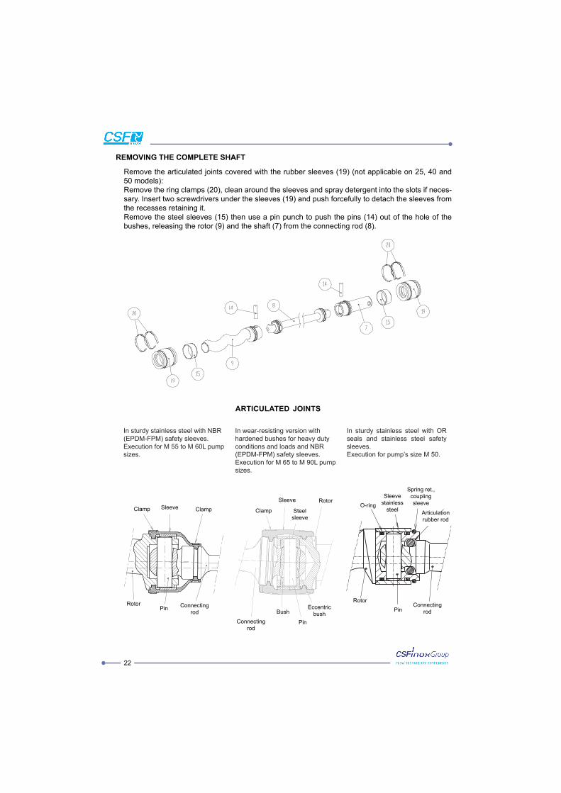
In sturdy stainless steel with NBR
(EPDM-FPM) safety sleeves.
Execution for
sizes.
In wear-resisting version with
conditions and loads and NBR
(EPDM-FPM) safety sleeves.
sizes.
In sturdy stainless steel with OR
seals and stainless steel safety
sleeves.
REMOVING THE COMPLETE SHAFT
-
the recesses retaining it.
Remove the steel sleeves (15) then use a pin punch to push the pins (14) out of the hole of the
ARTICULATED JOINTS
Clamp
Sleeve Rotor
Bush
Connecting
rodPin
Eccentric
Steel
sleeve
Clamp Sleeve Clamp
RotorPin
Connecting
rod
O-ring
Sleeve
stainless
steel
coupling
sleeve
Articulation
Connecting
rodPin
Rotor

23
12 12
PUMP REASSEMBLY
-
and perfectly aligned with the spherical part.

24
MAINTENANCE
Reduction unit
N.B.: When the reduction unit is stopped, the oil level must never disappear below the level
indicator. Oil must always be visible in the window.
Pump
pumping parts or seals are damaged in any way and prevent the rotating parts from sticking together.
Start the pump for the time necessary to achieve complete cleaning.
Pneumatic column and rotating table
prevent and avoid endangering persons and equipment.
Pict. 8

25
A
B
C
D
WASHING CYCLE FOR PUMPS USED TO HANDLE FOODSTUFF PRODUCTS
-
ning. A CIP (cleaning in place) procedure is carried out to clean the pump.
CIP PROCEDURE
1) Wash with clean water to empty the pump of any product
NB
This will clean the interior of the pump while limiting mechanical stress.
that the phases are carried out alternating the direction of rotation.
There is a version with suction port in two pieces. This is in order to achieve alternative solutions relating
to various uses and the need to perform CIP washing at the end of the cycle.
B = immersed port with suction cone for dense products.

26
SECTIONAL DRAWINGS WITH PART LISTS
Sectional drawing OF PNEUMATIC VERTICAL HOIST MAV 65-70L
VIEW FROM J

27
Part list OF PNEUMATIC VERTICAL HOIST MAV 65-70L
356 1 511 Nut 2
354 1 2
353 6 2
352 Plate 1 2
351 1 1
1 1
4 1
348 Protective guard 2 Pneumatic panel 1
346 16 4
336 Plug 1 Foot “C” 1
334 Foot 2 Fitting 1
328 2 1
323 6 2
322 24 2
321 2 377 1
318 2 376 1
316 4 371 2
311 Handle 1 Coupling 1
2 Coupling 1
Rail 2 368 Flow regulator 2
Hoist 2 367 Stop valve 2
Arm 1 366 6
1 365 Foot “L” 1
1 362 Cylinder 1
236 Air treatment group 1 357 2
Pos. Denomination Q.ty Pos. Denomination Q.ty

28
Sectional drawing OF FIXED PNEUMATIC VERTICAL COLUMN MAV 65-70L-80-90L
VIEW FROM J

Part list OF FIXED PNEUMATIC VERTICAL COLUMN MAV 65-70L-80-90L
365 Foot “L” 2
362 Cylinder 1 511 Nut 2
357 2 2
356 1 2
354 1 2
353 6 1
352 Plate 1 1
351 1 1
1 Pneumatic panel 1
4 Fitting 1
348 Protective guard 2 1
336 Plug 1 2
323 6 2
322 24 377 1
318 2 376 1
Rail 2 371 2
Hoist 2 Coupling 1
Arm 1 Coupling 1
1 368 Flow regulator 2
1 367 Stop valve 2
236 Air treatment group 1 366 6
Pos. Denomination Q.ty Pos. Denomination Q.ty
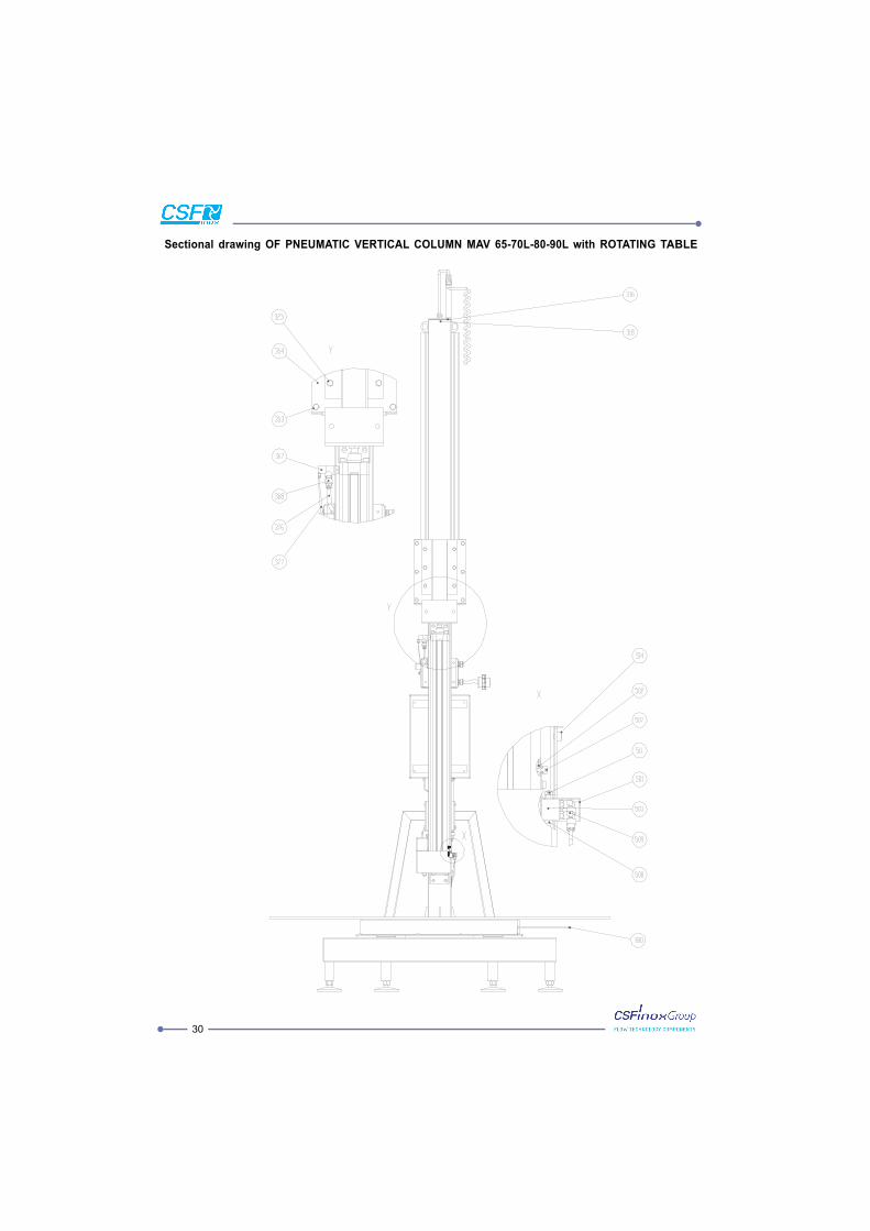
Sectional drawing OF PNEUMATIC VERTICAL COLUMN MAV 65-70L-80-90L with ROTATING TABLE

31
VIEW FROM J

32
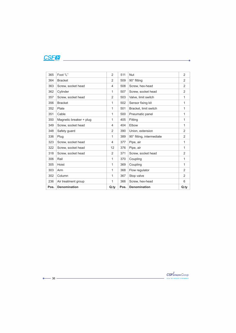
Part list OF PNEUMATIC VERTICAL COLUMN MAV 65-70L-80-90L with ROTATING TABLE
362 Cylinder 1 514 4
361 Screw 16 513 1
1 511 Nut 2
16 2
358 Bearing 1 2
357 2 2
356 Bracket 1 1
354 1 1
353 6 1
352 Plate 1 Pneumatic panel 1
351 1 Fitting 1
1 1
4 2
348 Safety guard 2 2
336 Plug 1 1
334 6 377 1
323 6 376 1
322 24 375 Dowel 1
318 2 374 8
316 4 373 Protective guard 1
Column reinforcement 2 371 2
Rail 2 Coupling 1
Hoist 2 Coupling 1
Arm 1 368 Flow regulator 2
Column 1 367 Stop valve 2
1 366 6
236 Air treatment group 1 365 Foot “L” 2
Pos. Denomination Q.ty Pos. Denomination Q.ty

33
Sectional drawing OF PNEUMATIC VERTICAL HOIST MAV 50-60L

34
Part list OF PNEUMATIC VERTICAL HOIST MAV 50-60L
362 Cylinder 1 511 Nut 2
357 2 2
356 Bracket 1 2
352 Plate 1 2
351 1 1
1 1
4 1
348 Protective guard 2 Pneumatic panel 1
346 16 4
336 Plug 1 Flange 1
334 Foot 2 Fitting 1
328 2 1
323 4 2
322 12 2
321 2 377 1
318 2 376 1
316 4 371 2
311 Handle 1 Coupling 1
2 Coupling 1
Rail 1 368 Flow regulator 2
Hoist 1 367 Stop valve 2
Arm 1 366 6
1 365 Foot “L” 1
1 364 Bracket 2
236 Air treatment group 1 363 4
Pos. Denomination Q.ty Pos. Denomination Q.ty

35
Sectional drawing OF FIXED PNEUMATIC VERTICAL COLUMN MAV 50-60L
36
365 Foot “L” 2 511 Nut 2
364 Bracket 2 2
363 4 2
362 Cylinder 1 2
357 2 1
356 Bracket 1 1
352 Plate 1 1
351 1 Pneumatic panel 1
1 Fitting 1
4 1
348 Safety guard 2 2
336 Plug 1 2
323 4 377 1
322 12 376 1
318 2 371 2
Rail 1 Coupling 1
Hoist 1 Coupling 1
Arm 1 368 Flow regulator 2
Column 1 367 Stop valve 2
236 Air treatment group 1 366 6
Pos. Denomination Q.ty Pos. Denomination Q.ty

37
The Chairman
Cav. P.I. Rolando Paterlini
DECLARATION OF CONFORMITY
PROGRESSIVE CAVITY PUMP WITH PNEUMATIC VERTICAL SYSTEM
EC declaration of conformity
2014/35/EC: electric equipment designed for use within certain voltage limits
2014/30/EC:
Food products-contact suitability declaration:
Strada per Bibbiano, 7
Montecchio Emilia (R.E.)
ITALIA

38
DECLARATION OF CONFORMITY
PNEUMATIC VERTICAL SYSTEM FOR PROGRESSIVE CAVITY PUMP
Manufacturer declaration (Ann. II.B, 2006/42/EC)
2014/35/EC: electric equipment designed for use within certain voltage limits
2014/30/EC:
Strada per Bibbiano, 7
Montecchio Emilia (R.E.)
ITALIA
The Chairman
Cav. P.I. Rolando Paterlini

cod.
DO
CIC
AR
MV
3E
nglis
h language
this document nor for the information contained herein. In
the data and drawings provided. Please note that the technical
document.
TECHNICAL SERVICE