HZR 65 - Technische Alternative
60
HZR 65 Version P5.6 EN Manual Version 9 Universal heating controller Operation Installation instructions en
-
Upload
khangminh22 -
Category
Documents
-
view
0 -
download
0
Transcript of HZR 65 - Technische Alternative
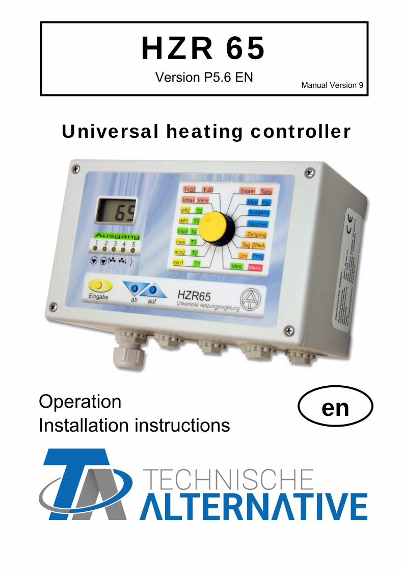
HZR 65 Version P5.6 EN
Manual Version 9
Universal heating controller
Operation Installation instructions
en

2

3
Contents
Safety requirements ......................................................................................... 4 Maintenance ...................................................................................................... 4 Generally applicable rules ............................................................................... 5
Diagram 0: Solid fuel boiler, buffer tank, heating circuit, requirement additional heating .. 6 Diagram 16: Automatic boiler, hot water tank, heating circuit, burner requirement ........... 8 Diagram 32: Automatic boiler, (combined) buffer, heating circuit, burner requirement ... 10 Diagram 48: buffer, hot water tank, heating circuit, burner requirement ......................... 12 Diagram 64: Solid fuel boiler, buffer, hot water tank, heating circuit .............................. 14 Diagram 80: Solar power unit, (combined) buffer tank, heating circuit, burner requirement ........................................................................................................................................ 17 Diagram 96: Boiler (or buffer tank), hot water tank, 2 heating circuits ........................... 20 Diagram 112: Heat pump control and requirement, heating circuit pump, solar collector ........................................................................................................................................ 22 Diagram 128: Buffer tank, heating circuit via pre-mixed district heating pipe, switch-over valve hot water, heating requirement resp. feed pump .................................................... 23 Diagram 144: Automatic boiler, tank, mixer for increasing return, heating circuit pump, burner requirement .......................................................................................................... 25
Installing instructions ..................................................................................... 27 Installing the sensor(s) ...................................................................................................... 27 Installing the unit ................................................................................................................ 28 Electrical connection .......................................................................................................... 28 Data line (DL) .................................................................................................................... 29
Selector switch ................................................................................................ 30 Mod (Operating mode) - Par (Parameters) ........................................................................ 34 Room sensor RASPT ........................................................................................................ 35 Frost protection conditions for heating circuit .................................................................... 35
Basic principle of heat curve .................................................................................................. 36 Setting the time switch function ............................................................................................. 37 Menu ................................................................................................................. 39
Mixer control parameter Mr................................................................................................ 40 Heating circuit pump parameter HPu ................................................................................. 43 Legionella protection function LES .................................................................................... 45 Sensor type Sen ................................................................................................................ 46 After-running time PnL ....................................................................................................... 47 Switching hystereses HSt .................................................................................................. 48 Pump speed control Pd1, Pd2 ........................................................................................... 49
Technical Data ................................................................................................. 52 Table of settings ............................................................................................. 53 Instructions for troubleshooting ................................................................... 55

4
Safety requirements All installation and wiring work on the controller must only be carried out in a zero-volts state.
The opening, connection and commissioning of the device may only be carried out by competent personnel. In so doing, all local security requirements must be adhered to.
The device corresponds to the latest state of the art and fulfills all necessary safety condi-tions. It may only be used or deployed in accordance with the technical data and the safety conditions and rules listed below. When using the device, the legal and safety regulations apposite to the particular use are also to be observed. The device must only be installed in a dry interior room.
It must be possible to isolate the controller from the mains using an all-pole isolating device (plug/socket or double pole isolator).
Before starting installation or wiring work, the controller must be completely isolated from the mains voltage and protected against being switched back on. Never interchange the safety extra-low voltage connections (sensor connections) with the 230V connections. De-structive and life-threatening voltages at the device and the connected sensors may occur.
For safety reasons, the system should only be left in manual mode when testing. In this operating mode, no maximum temperatures or sensor functions are monitored.
Safe operation is no longer possible if the controller or connected equipment exhibits visual damage, no longer functions or has been stored for a lengthy period of time under unsuitable conditions. If this is the case, place the controller and equipment out of service and secure against unintentional use.
Maintenance The system does not require maintenance if handled and used properly. Use a cloth moistened with soft alcohol (such as spirit) to clean. Harsh cleaning agents and solvents such as chlorethenes or tri-gases are not admissible. As the components relevant to accuracy are not subjected to loads if used properly, long-term deviation is very low. The unit thus cannot be adjusted. Hence, no calibration is possi-ble. The design characteristics of the unit must not be changed during repairs. Spare parts must correspond to the original parts used to restore the manufactured condition.

5
Generally applicable rules for the following diagrams:
The hydraulic diagrams of this manual are only diagrams in principle. They do not de-scribe or replace a professional system development. There is no guarantee for func-tion if directly copied.
When used for floor and/or wall heaters: Here, a safety thermostat must be used just as with conventional heater controllers. It has to switch off the heating circuit pump if there is overheating regardless of the output from the controller to prevent indirect damage from excess temperatures.
It is necessary to set all „Required settings“ mentioned in the hydraulic diagrams.
"All programs +1 (+2, +4, +8)" indicates that the selected program number can be in-creased by the sum total of these numbers.
Example: Diagram 16, program 19 (=16+1+2): basic function (automatic boiler, hot water tank, heating circuit, burner requirement) & boiler priority & switching the burner requirement over 2 sensors.
The term „heating = active“ in the link formulas describes the conditions specified in the menu heating pumps parameters “HPu” for additional release resp. blocking condi-tions of the heating pump and the mixer. According to the factory settings heating pump and mixer are released, when the calculated nominal flow temperature “Vsoll” exceeds the minimum flow temperature “Vmin”.
The factory settings cause the heating pump switch-off, when the calculated nominal flow temperature “Vsoll” falls below the adjusted minimum flow temperature “Vmin”. The mixer will be closed, when the heating pump is switched off. The temperature threshold for frost protection mode is set to 5.0°C ex works and the mixer operating mode to outdoor temperature control (Atr).
Frost protection heating circuit: The heating circuit pump A1 will be switched on under certain conditions (see chapter “Frost protection conditions for heating circuit”).
Frost protection tanks: According to the program the burner requirement A5 and/or load pump A2 will be activated when the temperature falls below frost the protection temperature at a certain sensor. Programs of diagram 64 as well as programs 112, 113, 130 and 131 have no frost protection of tanks.
With activated legionella protection function the thermostat function of the hot water tank sensor affects the feed pump and the burner requirement.
The potential-free output A5 (situated in the right part of the housing below the sensor terminals) is mainly arranged for boiler requirement of fossil fuel or pellets boilers. If this output is used for controlling a pump (e.g. diagram 64), a connection between supply line (phase L) and output terminal W has to be assembled.
In diagrams with a holding circuit (= burner requirement with a sensor, shut-down function with another one), the shut-down transducer is “dominant”. In other words, if improper parameters or sensor installation leads to the fulfillment of both the shut-on and shut-off conditions, the shut-off condition has priority.

6
Diagram 0: Solid fuel boiler, buffer tank, heating circuit, requirement additional heating
Sensors Outputs T1…. Boiler A1…. Heat circuit pump T2…. Tank top A2…. Tank feed pump T3…. Tank bottom A3…. Mixer open T4…. Heating circuit flow A4…. Mixer close T5…. Outdoor temperature A5…. Burner requirement T6…. Room sensor
Basic function (P0): Release of heating circuit pump A1 according to boiler and buffer temperature, activation of buffer feed pump A2, burner requirement applying to buffer. A1 = (T1> min1 or T2 > min2) & (heating = active) A2 = T1 > min1 & T1 > T3 + diff1 A5 = T2 < max
A1 off A2 off T1 < min1 and T2 < min2 T1 < min1 diff1 A1 on A2 on Switch-off cond. HPu T3 A1 off
Required settings: min1 …switch-on thresh. T1 A1,2 min2 … switch-on thresh.T2 A1 max …burner requirement T2 A5 diff1 …boiler T1 – buffer T3 A2 diff2 …see programs 2, 3, 4, 5 Vmax, Vmin T+20, T-20 Tnorm, Tabs Mixer control parameter Mr Heating pump parameter HPu Time program
Burner A5
T2 < max
A5… requirement additional heating

7
Program 1: Burner requirement A5 refers to sensor T3
A5 = T3 < max Program 2: Separated switch-on and switch-off thresholds for burner requirement. A5 on = T2 < min2 + diff2 A5 off = T2 > max Program 3: as program 2, but switch-off threshold refers to T3 (holding circuit). A5 on = T2 < min2 + diff2 A5 off = T3 > max Program 4: Burner requirement refers to nominal flow temperature “Vsoll”.
A5 = T2 < Vsoll + diff2 & (heating = active) Program 5: Separated switch-on and switch-off thresholds for burner requirement. Burner
requirement refers to nominal flow temperature “Vsoll”, switch-off threshold re-fers to T3 (holding circuit).
A5 on = T2 < Vsoll + diff2 & (heating = active) A5 off = T3 > Vsoll + diff2 Program 6: Separated switch-on and switch-off thresholds for burner requirement. Burner
requirement refers to nominal flow temperature “Vsoll” A5 on = T2 < Vsoll + diff2 & (heating = active) A5 off = T2 > max Program 7: Separated switch-on and switch-off thresholds for burner requirement. Burner
requirement refers to nominal flow temperature “Vsoll”, switch-off threshold re-fers to T3 (holding circuit).
A5 on = T2 < Vsoll + diff2 & (heating = active) A5 off = T3 > max all programs +8: Burner requirement is only allowed, if solid fuel boiler is cold. A5 (+8) = T1 < min1 & A5 all programs +160: Heating circuit pump A1 is only released by buffer tank temperature T2 and not by boiler temperature T1.
A1 = T2 > min2 & (heating = active) Time programs are possible for heating circuit A1 and burner requirement A5

8
Diagram 16: Automatic boiler, hot water tank, heating circuit, burner requirement
Sensors Outputs T1…. Boiler A1…. Heat circuit pump T2…. Tank top A2…. Tank feed pump T3…. Tank bottom A3…. Mixer open T4…. Heat circuit flow A4…. Mixer close T5…. Outdoor temperature A5…. Burner requirement T6…. Room sensor
Basic function (P16): No buffer tank; tank feed pump = A2; burner requirement = A5. For sliding boiler operation without mixer: It makes sense to set the thresholds min1 and min2 to 5°C (=no function) and to activate the pump switch-off condition Vsoll < Vmin (Menu HPu). Heating not active: Switch-off the burner requirement when nominal tank temperature max is reached. Tank feed pump is still active until boiler temperature falls below min1 for discharge of the boiler residual energy.
Required settings: min1 …switch-on thresh. T1 A1,2 min2 …switch-on thresh. T1 A5 max …limit tank T2 A2,5 diff1 …boiler T1 – tank T2 A2 diff2 …boiler T1 – Vsoll A5 Vmax, Vmin, T+20, T-20, Tnorm, Tabs, mixer control parameter Mr heating pump parameter HPu, time program tp
A1 off A2 off T1 < min1 T1 < min1 diff1 A1 on A2 on Switch-off cond. T2 > max HPu (if heating = active) A1 off A2 off
Boiler requirement A5 T2 < max
and time program (A2)
or
heating active and T1 < min2 or
heating active and T1 < Vsoll + diff2 (Vsoll = nominal flow temperature)
A5 = burner requirement
Pellets-or fossilfuel boiler
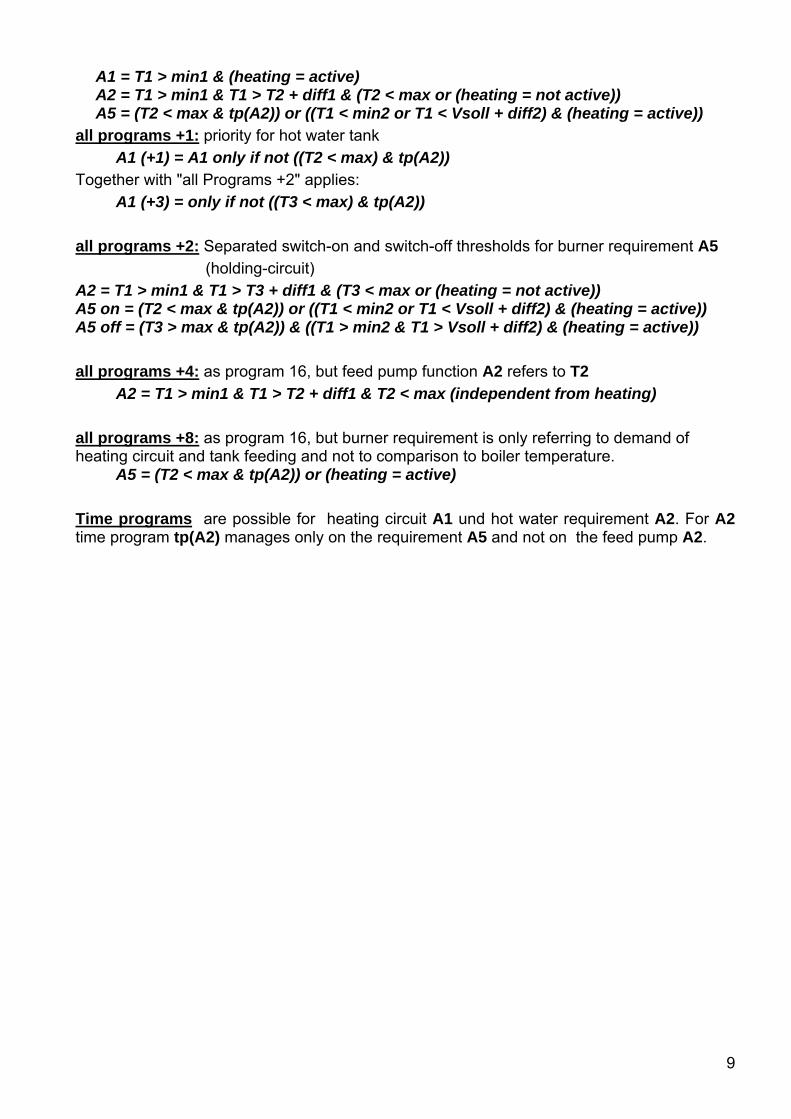
9
A1 = T1 > min1 & (heating = active) A2 = T1 > min1 & T1 > T2 + diff1 & (T2 < max or (heating = not active)) A5 = (T2 < max & tp(A2)) or ((T1 < min2 or T1 < Vsoll + diff2) & (heating = active)) all programs +1: priority for hot water tank A1 (+1) = A1 only if not ((T2 < max) & tp(A2)) Together with "all Programs +2" applies: A1 (+3) = only if not ((T3 < max) & tp(A2)) all programs +2: Separated switch-on and switch-off thresholds for burner requirement A5 (holding-circuit) A2 = T1 > min1 & T1 > T3 + diff1 & (T3 < max or (heating = not active)) A5 on = (T2 < max & tp(A2)) or ((T1 < min2 or T1 < Vsoll + diff2) & (heating = active)) A5 off = (T3 > max & tp(A2)) & ((T1 > min2 & T1 > Vsoll + diff2) & (heating = active)) all programs +4: as program 16, but feed pump function A2 refers to T2 A2 = T1 > min1 & T1 > T2 + diff1 & T2 < max (independent from heating) all programs +8: as program 16, but burner requirement is only referring to demand of heating circuit and tank feeding and not to comparison to boiler temperature. A5 = (T2 < max & tp(A2)) or (heating = active) Time programs are possible for heating circuit A1 und hot water requirement A2. For A2 time program tp(A2) manages only on the requirement A5 and not on the feed pump A2.

10
Diagram 32: Automatic boiler, (combined) buffer, heating circuit, burner require-ment
Sensors Outputs T1…. Boiler A1…. Heating circuit pump T2…. Tank top A2…. Tank feed pump T3…. Tank center A3…. Mixer open T4…. Heating circuit flow A4…. Mixer close T5…. Outdoor temperature A5…. Burner requirement T6…. Room sensor
Basic function (P32): The combined tank is maintained at temperature. Tank feed pump A2; mixer control A3+A4; burner requirement A5. Sensor T1 is available for eventual speed control function for boiler flow (A2). A1 = T3 > min2 & (heating = active) A2 = T1 > min1 & T1 > T3 + diff1 A5 = T2 < max or (T3 < Vsoll + diff2 & (heating = active))
Required settings: min1 …switch-on thresh. T1 A2 min2 …switch-on thresh. T3 A1 min2 …additional used with programs 33, 34 max …limit T2 (T3) A5 diff1 …boiler T1 – tank c. T3 A2 diff2 … Vsoll – tank cent. T3 A5 Vmax, Vmin, T+20, T-20, Tnorm, Tabs, mixer control parameter Mr heating pump parameter HPu, time program
A1 off A2 off T3 < min2 T1 < min1 diff1 A1 on A2 on Switch-off cond. HPu T3 A1 off
Burner requirement A5 T2 < max
or
heating active and T3 < Vsoll + diff2 (Vsoll = nominal flow temperature)
A5 = burner requirement
Pellets- or fossil fuel boiler

11
Program 33: Separated switch-on and switch-off thresholds for burner requirement
A5 on = T2 < min2 + diff2 A5 off = T2 > max Program 34: as program 33, but switch-off threshold on T3 (holding-circuit). A5 on = T2 < min2 + diff2 A5 off = T3 > max Program 35: Holding circuit with difference on nominal flow temperature Vsoll A1 = T2 > min2 & (heating = active) A2 = T1 > min1 & T1 > T3 + diff1
A5 on = T2 < max or (T2 < Vsoll + diff1 & (heating = active)) A5 off = T2 > max & (T3 > Vsoll + diff2 & (heating = active)) Program 36: Heating circuit pump and burner requirement are separated.
A1 = T2 > min2 & (heating = active) A2 = T1 > min1 & T1 > T3 + diff1 A5 = T3 < max all programs +8: Buffer feed pump A2 is switched on immediately with burner requirement (for fuel value units with minimum circulation quantity of water) A2 = A2 or A5 Time programs are possible for heating circuit A1 and burner requirement A5. For A5 the time program manages only on the hot water requirement A2, because the burner require-ment is linked with A1 (heating active).
A1 off A2 off T2 < min2 T1 < min1 diff1 A1 on A2 on Switch-off cond. HPu T3 A1 off
Boiler requirement A5 OFF
T2 > max and heating active & T3 > Vsoll + diff2
(Vsoll = nominal flow temperature)
Boiler requirement A5 ON
T2 < max or heating active & T2 < Vsoll + diff1

12
Diagram 48: buffer, hot water tank, heating circuit, burner requirement
Sensors Outputs T1…. Buffer top A1…. Heating circuit pump T2…. freely useable A2…. Hot water tank feed pump T3…. Hot water tank bottom A3…. Mixer open T4…. Heating circuit flow A4…. Mixer close T5…. Outdoor temperature A5…. Burner requirement T6…. Room sensor
Basic function (P48): Controlling the heating circuit pump A1; hot water feed pump A2; burner requirement A5 A1 = T1 > min1 & (heating = active) A2 = T1 > min1 & T1 > T3 + diff1 & T3 < max A5 on = T1 < min2 A5 off = T1 > min2 + diff2
Required settings: min1 …switch-on thresh. T1 A1,2 min2 …switch-on thresh. T1 A5 max …limit hot water tank T3 A2 diff1 …buffer top T1 – hot water tank T3 A2 diff2 … buffer top T1 A5 Vmax, Vmin, T+20, T-20, Tnorm, Tabs, mixer control parameter Mr heating pump parameter HPu, time program
A1 off A2 off T1 < min1 T1 < min1 diff1 A1 on A2 on Switch-off cond. HPu T3 > max A1 off A2 off
Burner requirement A5 ON
T1 < min2
OFF T1 > min2 + diff2
A5 = burner requirement

13
Program 49: as program 48, but switch-off threshold of burner requirement on T2 (holding-circuit)
A5 on = T1 < min2 A5 off = T2 > min2 + diff2 Program 50: Burner requirement referring to nominal flow temperature Vsoll and T2
A5 = T2 < min2 or T1 < Vsoll + diff2 & (heating = active) Program 51: as program 50, but in consideration of hot water tank temperature T3 A5 = T3 < min2 or T1 < Vsoll + diff2 & (heating = active) Program 52: separated sensors for switch-on and switch-off threshold of burner requirement
(holding-circuit) A5 on = T1 < Vsoll + diff2 & (heating = active) A5 off = T2 > min2 Program 53: as program 52, but in consideration of the hot water tank temperature T3
(holding-circuit) A5 on = T3 < max & (T1 < min1 or T1 < T3 + diff1) or (T1 < Vsoll + diff2 & (heating = active))
A5 off = T2 > min2 & T3 > max Program 54,55: as programs 52, 53, but A2 (hot water) has priority to A1 A1 (54,55) = A1 only if not ((T3 < max) & tp(A2)) all programs +8: Second heating source besides buffer with sensor T2.
All conditions at T1 apply to T2 too. The higher temperature is active. All conditions only at T2 remain unchanged. Example: Program 56 (=48+8) A1 = (T1 > min1 or T2 > min1) & (heating = active) A2 = (T1 > min1 or T2 > min1) & (T1 > T3 + diff1 or T2 > T3 + diff1) & T3 < max A5 on = T1 < min2 and T2 > min2 A5 off = T2 > min2 + diff2 or T1 > min2 + diff2 Example: Program 57 (=49+8)
A1 = (T1 > min1 or T2 > min1) & (heating = active) A2 = (T1 > min1 or T2 > min1) & (T1 > T3 + diff1 or T2 > T3 + diff1) & T3 < max A5 on = T1 < min2 and T2 > min2 A5 off = T2 > min2 + diff2
Time programs are possible for A1, A2 and A5. Using program 50, 51 or 53 the time pro-gram for A5 manages only on burner requirement for hot water service.

14
Diagram 64: Solid fuel boiler, buffer, hot water tank, heating circuit
Sensors Outputs T1…. Boiler A1…. Heating circuit pump T2…. Buffer top A2..Hot water tank feed pumpT3…. Hot water tank bottom A3…. Mixer open T4…. Heating circuit flow A4…. Mixer close T5…. Outdoor temperature or buffer bottom (all programs +4)
A5…. Buffer feed pump
T6…. Room sensor or buffer bottom (all programs +2) T7…. Buffer bottom (all programs +1)
Basic function (P64): Enable of heating circuit pump A1, when boiler or buffer tank tem-perature have exceeded their minimum thresholds; controlling of hot water tank feed pump A2; mixer control A3 & A4; Controlling of buffer tank feed pump A5.
A1 = (T1 > min1 or T2 > min2) & (heating = active) A2 = T2 > min2 & T2 > T3 + diff1 & T3 < max A5 = T1 > min1 & T1 > T2 + diff2
(T5)(T6)(T7)
Required settings: min1 …switch-on thresh. T1 A1,5 min2 … switch-on thresh.T2 A1,2 max …limit hot water tank T3 A2 diff1 …buffer T2 – hw tank T3 A2 diff2 … boiler T1 - buffer T2 A5 Vmax, Vmin, T+20, T-20, Tnorm, Tabs, mixer control parameter Mr heating pump parameter HPu, time program
A1 off A2 off A5 off T1 < min1 T2 < min2 T1 < min1 and T2 < min2 diff1 diff2 A1 on A2 on A5 on Switch-off cond. HPu T3 > max T2 A1 off A2 off

15
all programs +1: Feeding the hot water tank refers to the boiler as to the buffer tank temper-ature. A2 = ((T1 > min1 & T1 > T3 + diff1) or (T2 > min2 & T2 > T3 + diff1)) & T3 < max Sensor 7 for all programs +1: The function of this program variation can be optimized by a 7th sensor. The sensor T7 must be the same senor type as sensor T2, i.e. both sensors must be either KTY or PT1000. The controller switches over from sensor T2 to sensor T7 (tank bottom) when buffer feed pump A5 is required. As no information exists about the top tank temperature at that time, it is necessary to use program 65 (64 & 1) to make sure, that the boiler temperature T1 has alternative information for switching hot water tank pump A2.
Schematic wiring diagram and operation mode:
The temperature of sensor T7 is displayed instead of sensor T2 when output A5 is active.
A1 off A2 off A2 off A5 off T1 < min1 T2 < min2 or T1 < min1 T1 < min1 and T2 < min2 diff1 diff 1 diff2 A1 on A2 on A2 on A5 on Switch-off cond. HPu T3 > max T2 (T7) A1 off A2 off

16
all programs +2: Sensor T6 is not employed as room sensor, but as reference sensor for feeding buffer tank (tank bottom).
Note: T6 must be set as standard sensor (Std) (see selector switch position Mod – Par). In position “Par” the use of sensor T6 must be set:
rAS T6 is used as room sensor Std T6 is no room sensor, frost protection at T5 keeps active
Setting in menu mixer control parameter „Mr“: Atr = outdoor temperature control or Fir = fixed value control A5 = T1 > min1 & T1 > T6 + diff2
all programs +4: Sensor T5 is not employed as room sensor, but as reference sensor for feeding buffer tank (tank bottom). Outdoor temperature control for heating circuit is not possi-ble (not usable with „all programs +2). Note: Setting in menu mixer control parameter “Mr”: Fir = fixed value control, or using a room sensor rtr =room temperature control. A5 = T1 > min1 & T1 > T5 + diff2 all programs +8: Potential free contact A5 is linked out with output A2.
all programs +160: Heating circuit pump is enabled only by buffer tank temperature T2 and not by boiler temperature T1. A1 = T2 > min2 & (heating = active) similar programs to diagram above: see program 85 and 86 (after diagram 80)
Time programs are possible for heating circuit A1 and hot water tank feeding A2

17
Diagram 80: Solar power unit, (combined) buffer tank, heating circuit, burner requirement
Sensors Outputs T1…. Collector A1…. Heating circuit pump T2…. Tank top A2…. Solar pump T3…. Tank bottom A3…. Mixer open T4…. Heating circuit flow A4…. Mixer close T5…. Outdoor temperature A5…. Burner requirement T6…. Room sensor
Basic function (P80): Enable of heating circuit pump by minimum threshold min1 at sensor T2; control of solar pump A2 and burner requirement A5. A1 = T2 > min1 & (heating = active) A2 = T1 > T3 + diff1 & T3 < max A5 = T2 < min2
Program 81: Burner requirement referring to nominal flow temperature Vsoll; time program for A1 defines the burner requirement for heating circuit, time program linked with A5 hot water service. A5 = T2 < min2 or (T2 < Vsoll + diff2 & (heating = active))
Required settings: min1 …switch-on thresh. T2 A1 min2 …switch-on thresh. T2 A5 max …limit tank bottom T3 A2 diff1 …Coll. T1 – Tk.bottom T3 A2 diff2 …see progr.81 (T2-Vsoll) A5 Vmax, Vmin T+20, T-20 Tnorm, Tabs mixer control parameter Mr heating circuit pump parameter HPu time program
A1 off T2 < min1 T1 diff1 A1 on A2 on Switch-off cond. HPu T3 > max A1 off A2 off
Burner A5
T2 < min2
A5 = burner requirement

18
Program 82: Instead of burner requirement (program 80) A5 is a hot water tank feed pump. Sensor T6 is no room sensor, but a tank sensor. Note: T6 must be set as standard sensor (Std) (see selector switch position Mod – Par). In position “Par” the use of sensor T6 must be set:
rAS T6 is used as room sensor Std T6 is no room sensor, frost protection at T5 keeps active
Setting in menu mixer control parameter „Mr“: Atr = outdoor temperature control or Fir = fixed value control A5 = T2 > min1 & T2 > T6 + diff2 & T6 < min2 Program 83: A5 is a hot water tank feed pump. Therefore the sensor T6 is situated in the boiler. Note: T6 must be set as standard sensor (Std) (see selector switch position Mod – Par). Heating circuit pump A1 is enabled by buffer tank or boiler temperature. A1 = T2 > min1 or T6 > min2 & (heating = active) A5 = T6 > min2 & T6 > T3 + diff2 Program 84: Enable of heating circuit pump A1 without observance of any energy source temperature. A5 is a feed pump between T2 and T3 without maximum threshold. A1 = (heating = active) A2 = T1 > T3 + diff1 & T3 < max A5 = T2 < min2 & (T2 > T3 + diff2)
A1 off A5 off T2 < min1 T1 T2 < min1 diff1 diff2 A1 on A2 on A5 on Switch-off cond. HPu T3 > max T6 > min2 A1 off A2 off A5 off

19
Program 85: A5 is a feed pump between boiler and buffer tank T2; A2 is the feed pump between boiler and hot water tank T3. A1 = T2 > min2 & (heating = active) A2 = T1 > min1 & T1 > T3 + diff1 & T3 < max A5 = T1 > min1 & (T1 > T2 + diff2) Program 86: A1 and A2 as program 85, but A5 refers to T6 (no room sensor). Note: T6 must be set as standard sensor (Std) (see selector switch position Mod – Par). A5 = T1 > min1 & (T1 > T6 + diff2) Time programs are possible for heating circuit A1, solar circuit A2 and burner requirement A5.
A1 off A2 off A5 off T2 < min2 T1 < min1 T1 < min1 diff1 diff2 A1 on A2 on A5 on Switch-off cond. HPu T3 > max T2 A1 off A2 off

20
Diagram 96: Boiler (or buffer tank), hot water tank, 2 heating circuits
Sensors Outputs T1…. Boiler A1…. Heating circuit pump 1 T2…. Heating circuit 2 return A2…. Heating circuit pump 2 T3…. Tank bottom A3…. Mixer open T4…. Heating circuit 1 flow A4…. Mixer close T5…. Outdoor temperature A5…. Tank feed pump T6…. Room sensor
Basic function (P96): Controlling of heating circuit pump A1, A2 and hot water tank feed pump A5: mixer control for heating circuit 1 (A3&A4); controlling of the second heating circuit can be reached by absolute value control of pump speed control. A1 = T1 > min1 & (heating = active) A2 = T1 > min1 & T1 > T2 + diff1 & T2 < min2 A5 = T1 > min1 & T1 > T3 + diff2 & T3 < max
Required settings: min1 …switch-on thresh. T1 A1,2 min2 …limit T2 A2 max …limit tank bottom T3 A5 diff1 …boiler T1 – h.c.2 T2 A2 diff2 … boiler T1 – tk. bott. T3 A5 Vmax, Vmin, T+20, T-20, Tnorm, Tabs, mixer control parameter Mr heating pump parameter HPu, time program, optionally: pump speed control Pd2 for heating circuit pump A2
A1 off A2 off A5 off T1 < min1 T1 < min1 T1 < min1 diff1 diff2 A1 on A2 on A5 on
Switch-off cond. HPu T2 > min2 T3 > max A1 off A2 off A5 off

21
Program 98: Combined buffer tank instead of boiler and hot water tank. Thus output A5 can be used for burner requirement by T1. A5 on = T1 < max A5 off = T1 > max + diff2 Program 100: as program 98, but switch-off threshold of burner requirement at T3 (holding-circuit). A5 on = T1 < max A5 off = T3 > max + diff2 Program 104: as programs 98 resp. 100, but burner requirement refers to nominal flow temperature and basic temperature (hot water). A5 on = T1 < max or T3 < Vsoll + diff2 & (heating = active) A5 off = T1 > max and T3 > Vsoll d fiff2 & (heating = active) all programs +1: The heating function (heating = active) refers also to output A2. A2 = T1 > min1 & T1 > T2 + diff1 & T2 < min2 & (heating = active) Time programs are possible for A1, A2 and A5.

22
Diagram 112: Heat pump control and requirement, heating circuit pump, solar collector, hot water tank
Sensors Outputs T1…. Collector A1…. Heating circuit pump T2…. Tank bottom A2…. Solar pump T3…. Tank top A3…. Differential function T4…. Heating circuit return A4…. Hot water tank feed pump T5…. Outdoor temperature A5…. Heat pump requirement T6…. Room sensor
Basic function (P112): Heating circuit pump is switched on for set run time tr if: heating active & return temperature T4 < Vsoll (nominal flow temperature depending on outdoor temperature) or set cycle time tc is over) When after run time tr the return temperature T4 < Vsoll, the heat pump is required by A5 (condition: blocking time tb is over). A1 and A5 will be switched off, when T4 > Vsoll + diff2. A1 = according to description above A2 = (T1 > min1) & (T1 > T2 + diff1) & (T2 < max) A3 = T1 > T3 + diff2 A4 = T3 < min2 A5 = T3 < min2 or heat pump requirement for heating Program 113: As program 112, but heating circuit pump is switched of when hot water requirement occurs (hot water priority).
Required settings: (Vsoll = nominal flow temperature) min1.... switch-on thresh. T1 A2 min2... hot water requirement T3 A4,5 max.... limit hot water tank T2 A2 diff1.... coll. T1-tank T2 A2 diff2.... switch-off thresh. return T4 - Vsoll A5 Vmax, Vmin, T+20, T-20, Tnorm, Tabs, heating pump parameter HPu, time program, Additional settings in menu PnL (ew = factory settings “ex works”): Tc ..... cycle time setting range: 0 to 90 minutes (tc0 - tc9) ew: tc3 (30 minutes) Tr ..... run time setting range: 0 to 9 minutes (tr0 - tr9) ew: tr2 (2 minutes) Tb ..... blocking time setting range: 0 - 90 minutes (tb0 - tb9) ew: tb3 (30 minutes)
A5 = Heat pumprequire-ment

23
Diagram 128: Buffer tank, heating circuit via pre-mixed district heating pipe, switch-over valve hot water, heating requirement resp. feed pump
Sensors Outputs T1…. Buffer tank top A1…. Heating circuit pump T2…. Buffer tank bottom A2…. 3-way valve hot water tank T3…. Hot water tank A3…. Mixer open T4…. Heating circuit flow A4…. Mixer close T5…. Outdoor temperature A5…. Burner requirement T6…. Room sensor
Basic function (P128): Heating circuit is supplied by pre-mixed district heating pipe. Heating circuit pump A1 runs for hot water requirement too; 3-way valve A2 opens for hot water requirement. A1 = T1 > min1 & (heating = active) or A2 (hot water requirement) A2 = T1 > min1 & T1 >T3 + diff1 & T3 < max A5 on = T1 < min2 A5 off = T1 > min2 + diff2
A5 = burner requirement
Required settings: min1 …switch-on thresh. T1 A1,2 min2 …boiler requirement T1 A5 max …limit hot water tank T3 A2 diff1 …buffer T1 – hot water tank T3 A2 diff2 … buffer T1 – min2 A5 Vmax, Vmin, T+20, T-20, Tnorm, Tabs, mixer control parameter Mr heating pump parameter HPu, time program,
A1 off A2 off T1 < min1 T1 < min1 diff1 A1 on A2 + A1 on Switch-off cond. HPu T3 > max A1 off A2 off
Burner requirement A5 ON
T1 < min2
OFF T1 > min2 + diff2

24
Program 129: As Program 128, but switch-off threshold of burner requirement refers to T2 (holding-circuit). A5 on = T1 < min2 A5 off = T2 < min2 + diff2 Program 130: A5 has feed pump function instead of burner requirement. Sensor T6 is not employed as room sensor, but as tank sensor.
Note: T6 must be set as standard sensor (Std) (see selector switch position Mod – Par). In position “Par” the use of sensor T6 must be set:
rAS T6 is used as room sensor Std T6 is no room sensor, frost protection at T5 keeps active
Setting in menu mixer control parameter „Mr“: Atr = outdoor temperature control or Fir = fixed value control A1 = T2 > min2 & (heating = active) or A2 A2 = T2 > min2 & T2 > T3 + diff1 & T3 < max A5 = T1 > min1 & T6 + diff2 Program 131: As program 130. Exchange of A2 with A5. A2 <=> A5
A1 off A2 off A5 off T2 < min2 T2 < min2 T1 < min1 diff1 diff2 A1 on A2 + A1 on A5 on Switch-off cond. HPu T3 > max T6 A1 off A2 off

25
Burner requirement
Diagram 144: Automatic boiler, tank, mixer for increasing return, heating circuit pump, burner requirement
Sensors Outputs T1…. Automatic boiler A1…. Feed pump T2…. Tank center A2…. Heating circuit pump T3…. Tank bottom A3…. Mixer open T4…. Return line boiler A4…. Mixer close T5…. Tank top A5…. Burner requirement T6…. Return heating circuit
Basic function (P144): Controlling of buffer feed pump A1 and heating circuit pump A2, controlling of return temperature by mixer A3&A4, burner requirement A5 (holding-circuit); heating circuit control can be applied by pump speed control.
A1 = T1 > min1 & T1 > T3 + diff1 A2 = T5 > min2 & T5 > T6 + diff2 & T6 < max A5 on = T2 < Vmin A5 off = T3 > Vmax
Required settings: min1 …switch-on thresh. T1 A1 min2 …switch-on thresh. T5 A2 max …heating circuit return line T6 A2 diff1 …boiler T1 – tank T3 A1 diff2 … tank T5 – heating circuit T6 A2 Vmin …burner requirement onT2 A5 Vmax … burner requirement off T3 A5 mixer control parameter Mr (fixed value control Fir:T+20, T-20), time program, optionally: pump speed control Pd2 for heating circuit pump A2
A1 off A2 off T1 < min1 T5 < min2 diff1 diff2 A1 on A2 on T3 T6 > max A2 off
Burner requirement A5 ON
T2 < Vmin
OFF T3 > Vmax

26
Program 145: Heating circuit pump is switched mainly by thermostat threshold min2, T5 = outdoor temperature.
A2 = T2 > min2 & (heating = active) Program 146: As Program 144, but heating circuit pump is switched by controlled system T2 – T6 instead of T5 – T6.
A2 = T2 > min2 & T2 > T6 + diff2 & T6 < max Time programs are possible for A2 and A5.

27
Installing instructions Installing the sensor(s)
Correct arrangement and installation of the sensors is extremely important for correct func-tioning of the system. It should be ascertained that the sensors are completely inserted in the immersion sleeves. The threaded cable connections can serve as strain relief. Fundamentally sensors should not be exposed to moisture (such as condensation) since this can diffuse through the cast resin and damage the sensor. If this happens, heating the sensor to 90°C for an hour might help. When using immersion sleeves in NIRO tanks (inoxydable) or pools particular attention must be given to their corrosion resistance. Boiler sensor (boiler flow): This sensor is either screwed into the boiler using an immer-sion sleeve or attached to the flow line at a short distance to the boiler (see also "clip-on sensors"). Buffer sensor: It is recommended to install the sensor in the upper part of the tank as a reference sensor using the immersion sleeve supplied. The best position as reference sensor for the load pump between the boiler and buffer is just above the return outlet. For tanks without a screw-in facility for the immersion sleeve the sensor can be inserted under the insulation against the wall of the tank if necessary. In this case attention should be paid to achieving a long-term secure seating (e.g. cable fastening). Clip-on sensor: Optimally secured using roll springs, pipe clamps or hose band clips to the line. Make sure the material used is suitable (corrosion, temperature resistance, etc.). Finally the sensor must be well insulated so that the exact pipe temperature is recorded without being influenced by the ambient temperature. Outdoor temperature sensor: This sensor is installed on the coldest wall (usually the north side) approx. one to two meters above ground level. Temperature influences from nearby air shafts, open windows, etc. are to be avoided.
Line extension All of the sensor cables with a cross-section of 0.75mm2 can be extended up to 30m. Beyond 30m they can be extended by use of a suitably larger cross section. The sensor and the probe can be connected by putting the heat-shrinkable tubing truncated to 4 cm over a wire and twisting the bare wire ends. The heat-shrinkable tubing is then pushed over the twisted bare ends and carefully heated (e.g. with a lighter) until this has closed tightly around the joint.
Cable laying In order to obtain interference-free signal transmission (to avoid measurement fluctuations)
the sensor lines must not be subject to interference factors. With the generally accepted use of unshielded cables sensor lines are to be laid in their own cable channel at least 20 cm away from mains cables.

28
Installing the unit CAUTION! ALWAYS PULL THE MAINS PLUG BEFORE OPENING THE CASE! Unscrew the 4 screws at the edges of the case. The controlling electronic is situated in the cover plate and is connected by a ribbon cable to the mains module, which is set in the basin of the case. The basin of the case can be screwed on through the two holes to the wall using the fastening screws provided (with the cable bushings downwards). For easier handling the mains module can be token out of the case. Electrical connection
Warning: The electrical connection should only be made by a professional electrician in accordance with the relevant local guidelines. The sensor lines may not be fed through the same cable channel as the supply voltage.
Notice: The system must be grounded to protect it from damage by lightening according to regulations; sensor failure caused by electrical storms or electrostatic charging can usually be traced to insufficient grounding.
All sensors and pumps resp. valves must be connected to the controller according to the numbering of the chosen diagram. All sensor grounds are interconnected and fully inter-changeable.
W..... root C S...... make contact NO Ö...... break contact NC
The relay output A4 can be made potential-free by setting the jumpers J1-J2-J3. For this
purpose the jumper J2 must be set in the center instead of jumpers J1 and J3 (standard).

29
W..... root C S...... make contact NO Ö...... break contact NC
The fifth output A5 is in the area of sensor terminals, which has a potential free switch-over
contact. The connections W (root C) and S (make contact NO) are normally used for burner requirement.
Data line (DL) The data line was specially developed for the UVR series and is only compatible with the products of Technische Alternative. It is only made for generating outputs and is suitable as interface to the PC for transferring the measured temperatures and output states.
Any cable with a cross section of 0.75 mm² can be used for the data link (e.g. twin-strand) having a max. length of 30 m. For longer cables, we recommend the use of shielded cable. Interface to PC: The data is cached via the data converter D-LOGG or boot loader BL-NET and transferred to the PC on request. An individual power pack (CAN-NT) is neces-sary for supplying power to the BL-NET!
7
Terminals T7 + T2 (see program 64 +1 )
2
sen
sor
sen
sor
sen
sor
sen
sor
sen
sor
sen
sor
dat
a lin
e
Mixer
open
closeBurner requirement

30
T+20 T-20 Tnorm Tabs
Vmax Vmin Mod Par
diff2 T6 Ausgang
diff1 T5 Mischer
Vsoll T4 Zeitprog
max T3 Tag ZP A
min2 T2 Uhr Prog
min1 T1 Vers. Menü
Selector switch The selector switch has 16 different positions. Each position has two functions (e.g. switch position min2 / T2). The value, which is nearer to the selector switch, will be displayed with-out pressing of the yellow key “Eingabe” (e.g. T2). By pressing the yellow key “Eingabe” (= “input”) the second value will be displayed (e.g. min2). The blue keys “ab” (= “down”) resp. “auf” (= “up”) change the settings. Holding the key pressed increases resp. decreases con-stantly the value, short taps cause a change of 1. The interior legend (e.g. T5 = displayed temperature of outdoor sensor 5) has no direct connection to the outside legend (e.g. diff1 = difference between 2 sensors).
T1 - T6 Actual temperature of the sensors
min1,2 The minimal threshold min generally prevents boilers from being clogged with soot. The hysteresis has an increasing effect, i.e. reaching the threshold plus hysteresis the output will switch on, falling below the threshold it will switch off. Factory setting (ex works = ew): min1 = 60°C, min2 = 30°C; setting range: 0 to 150 °C
max The maximum function limits the storage of tanks. The hysteresis has a decreasing effect, i.e. reaching the threshold the output will switch off, falling below the threshold minus hysteresis it will switch on again; ew: 70 °C; setting range: 0 to 150 °C
diff1,2 The output will be released, when the temperature difference between two set sensors exceeds this value. Normal set value: approx. 5K. The hysteresis has an increasing effect, i.e. reaching the temperature differ-ence plus hysteresis the output will switch on, falling below the differ-ence it will switch off; ew: diff1 and diff2 5.0 K; setting range: 0 to 99 K

31
Schematic representation of setting values:

32
Vsoll Nominal flow temperature, which is calculated based on measured temperatures and heating curve (not changeable check value). In normal cases it must be nearly the same value as temperature T4 (flow senor).
Vmin Even if the calculated nominal flow temperature is decreasing this threshold, the controller allows no lower temperature; ew = 25 °C; setting range: 0 to 99°C
Vmax Protecting function against overheating of temperature sensitive parts (e.g. floor heating pipes); no higher temperature is allowed for mixer control; ew = 80 °C; setting range: 0 to 99°C
T-20 For complete definition of the heat curve the second value for -20°C outdoor temperature is necessary. T-20 is the necessary flow temperature at -20°C outdoor temperature; ew = 30°C; setting range: 0 to 99°C
T+20 Necessary flow temperature at outdoor temperature of +20°C for reaching the desired room temperature; ew = 70°C; setting range: 0 to 99°C
Tnorm Desired room temperature for heating mode (heating temperature); ew = 20°C; setting range: 0 to 99°C
Tabs Desired room temperature for lowering mode (lowered temperature); ew = 15°C; setting range: 0 to 99°C
Mod Switching over between several modes (ew = Aut):
Aut – automatic mode FEI – holiday function nor – hold heating mode UrL – vacation function AbS – lowering mode Stb – standby function PAr – party function
Par Input of parameters for functions defined under Mod.
Aus-gang
(=Output)
Each output can be selected by pushing the blue keys auf / ab and can be set to “Ein” (=On), “Aus” (=Off) or AUTomatic mode by pressing the keys “Eingabe” and auf/ab simultaneously. Attention! If an output is set to “Ein” (=On) or “AUS” (=Off), the program functions have no influence to this output.
Mischer
(=Mixer)
Switching over mixer control between Automatic and „Hand“ (=manual mode) by simultaneous pressing the keys „Eingabe“ and “auf" or “ab”. Manual Change of mixer setting is possible with auf/ab, but after it the controller will balance the change in some minutes.
Zeitprog
(=time program)
Input of time programs; this function enables – depending on the program – blocking resp. enable of outputs and for A1 switch over between heating and lowering mode of the heating function.
Tag
(= day)
Actual day of the week resp. day, to which a time window is allocated at ZPA.
ZPA Allocation of time program („ZP“) to outputs („A“).
Uhr
(= clock)
Setting of the actual time, important for correct function of time windows. The controller has a power reserve of approx. 24 hours, i.e. when blackout longer than 24 hours occurs, time must be set again.

33
Prog Selection of the program number according to the chosen diagram. The pro-gram number defines the basic function of the controller and is the most important input. Setting by the blue keys ab/auf (down/up); ew = P 0
Vers In this switch position the software version of the computer is displayed (e.g. P5.6). It shows the “intelligence” of the controller and must be advertised to the manufacturer for enquiry calls. It cannot be changed.
Menü „Menü“ (= menu) allows the setting of about 50 different parameters, which are set ex works to standard settings. Sometimes it is necessary to change them. A change of these values should only be done, if the user has knowledge of all functions as these settings can change the basic features of the controller. Different parameters are stored in sub menus:
Mr....... Mixer control parameters Hpu..... Settings for heating circuit pump LES..... Legionella protection function SEn…. Sensor type – switch-over between KTY and PT1000 PnL...... After-running time Hst....... Hysteresis - setting of the hystereses for exact balancing of the system Pd1, 2... Pump speed control for outputs A1 and A2
The settings of the menu functions ex works can be restored at any time using the yellow key (“Eingabe” = entry) when plugging the unit in. The settings of all the parameters and menu functions ex works can be restored at any time using both blue keys (“ab/auf” = up/down) when plugging the unit in.

34
Mod (Operating mode) - Par (Parameters) The different operating modes refer exclusively to mixer control and heating circuit pump. All others outputs are still controlled according to program and setting in all operating modes. That concerns the standby function as well.
Automatic mode „Aut” Automatic mode switches over between normal heating mode and lowering mode due to
the time switch function. In parameter “Par” the application of the sensor T6 (room sensor or used in another way) must be set. Setting mode: Hold “Eingabe”, change with “ab/auf” key.
Par = rAS T6 is used as room sensor RAS = Std T6 is no room sensor, frost protection function keeps active over T5
= Unb T6 is no room sensor, no frost protection function
Normal heating mode „nor” Normal heating mode continues. Time switch function has no influence to heating mode.
No lowering mode will be activated. No selection of parameters!
Lowering mode „AbS” In lowering mode the room temperature will be kept at the level set in adjustment “Tabs”.
No selection of parameters! Party mode „PAr”
Party mode keeps the room temperature at the level of normal heating mode. For this case the time must be set in “Par”, at which the automatic mode should start again.
Note! “PAr” = Party operation mode, not to confuse with “Par” = Parameter
Holiday mode „FEI” When selecting this function and input of number of coming public holidays in “Par”, the
day of input will operate as Saturday and the specified number of days as Sundays. I.e. the time switch function during these days complies with these of Saturday resp. Sunday. After this time the function will be cancelled out of memory.
Vacation mode „Url” Setting the length of vacation in days (in „Par“) the room temperature will be kept during
the vacation at lowering temperature (“Tabs”). After this time the controller switches back to automatic mode and the function is cancelled out of memory.
Standby mode „Stb” By setting standby mode the controller operates only in frost protection mode. When the
outdoor temperature T5 decreases the frost protection threshold set in “Par”, the heating circuit operates in lowering mode.

35
Room sensor RASPT Operation mode: The room sensor RASPT is a special
development of „Technische Alternative” and is provided for installing in living rooms (reference room). It should not be installed near to a heating source or to a window.
It is possible to change the room temperature in heating mode in a range of approx. +/- 4°C and to select between several modes (automatic, normal, lowered and frost protec-tion mode).
Connection: The RASPT has to be connected to the termi-nal position T6 and sensor mass (ground).
Setting: Operating with controller HZR65 the room sensor must be defined as parameter “rAS” in automatic mode. Only in this case the controller detects the values of the sensor.
Frost protection conditions for heating circuit The frost protection limit is set in mode “Stb” (Standby) as parameter. Factory setting: +5°C, setting range: 0 – 99 °C
Mode Par - setting in mode Aut
Frost protection activation of heating-circuit pump (decreasing the frost protection limit)
Automatic/lowered/normal rAS only by room sensor T6, independent from outdoor sensor T5
Automatic/lowered/normal Std by outdoor sensor T5
Automatic/lowered/normal Unb no frost protection
Standby on the controller rAS by room sensor T6
and outdoor sensor T5
Standby on the controller Std by outdoor sensor T5
Standby on the controller Unb by outdoor sensor T5
Standby on room sensor RASPT
rAS only by room sensor T6, independent from outdoor sensor T5
Standby on room sensor RAS (KTY)
rAS only by outdoor sensor T5

36
Basic principle of heat curve This principle allows automatic temperature control of the heating circuit flow temperature depending on outdoor and room temperature. Description: By setting the values T+20 and T-20 it is possible to set the flow temperature of heating circuit, measured at T4 (flow temperature sensor). Switch position T-20 shows the desired heating circuit flow temperature at outdoor tem-perature of -20°C (measured at outdoor temperature sensor T5), while switch position T+20 indicates the flow temperature at outdoor temperature of +20°C. A line results from these values, whose rate of rise depends on settings of T-20 and T+20. Looking at the diagram it is possible to detect the nominal flow temperature at a certain outdoor temperature. In addition it is possible to limit the flow temperature to top and bottom with the values Vmax resp. Vmin. Setting: Setting the flow temperature at outdoor temperature -20°C: Selection position T-20 with the selector switch, changing the value by pushing the blue “ab/auf” keys to the desired value. Setting the flow temperature at outdoor temperature +20°C: Selector switch in same position, but holding the yellow “Eingabe” key when changing the value by pushing the blue “ab/auf” keys. Setting the minimal flow temperature: Selector switch in position Vmin, changing the value by blue „ab/auf“ keys. Setting the maximum flow temperature Vmax: Same selector position, but holding the yellow “Eingabe” key when changing the value by pushing the blue “ab/auf” keys.

37
Setting the time switch function As soon a time program is allocated to the heating circuit output A1 this function allows
normal heating mode only within the switch- on and switch-off times. I.e. the function switch-es over between normal heating and lowered mode. This function mode acts only on heat circuit with output A1.
In case of the other outputs switching according to program function is only allowed within the switch-on and switch-off times which are allocated to the output (except mixer outputs).
It is possible to select up to 5 time programs with each 3 switch-on and 3 switch-off times. Beginning with selection of a switching point (P1.1 to P5.6) with blue “ab/auf” keys it is pos-sible to allocate a switching time to the switching point by holding the yellow “Eingabe” key when changing the value by pushing the blue “ab/auf” keys (see flow chart for time program)
After setting the switching points the time programs must be allocated to outputs and days of the week (day by day Monday to Sunday or blocked for work days WT (Monday to Friday).
Following principles of programming switch time function have to be observed:
The same time programs can be allocated to several outputs and/or weekdays. For this purpose in position ZPA one day after the other must be selected (or with “WT” the block Monday to Friday) and a time program allocated to the desired output. If no time program is allocated to the output, the function according to the program is al-lowed, i.e. switch-on and switch-off according selected program with difference and thermostat function. If time windows overlap, the switch-on condition of the output will be preferred.
After completed allocation of time windows to weekday resp. week program the actual weekday must be set. Only after that the menu position may be left.
All switching points selected in “Zeitprog” with odd numbers (1, 3, 5) are switch-on times and all numbers with even numbers (2, 4, 6) are switch-off times.
Time switch function (example)
Time programs Allocation to output (A1 and/or A2) Allocation to weekday (Monday to Sunday)
Time program 1 (A1) Mo - Fr
Time program 2 (A1) Saturday
Normal mode
Lowering mode
Switching times

38
Time program P1 = time program 1 (setting range: P1 to P5)
1= switching point 1 (1, 3, 5 = on / 2, 4, 6 = off)
Short taps on “ab/auf” keys cause switching from P1.1 up to P5.6. 5.0 = switch-on time 05:00 am; setting range: 0.1 to 23.5 resolution = 10 minutes Short tap causes switching over between day and week program (Wt) Wt = Monday to Friday
switching over to the next week-day by “ab/auf” keys A1 = output 1(possible settings: A1, A2, A4, A5 – depending on program)
1 = time program 1 with 6 possible switching points
Short tap causes switching over between output A1, A2, A4 and A5 (depending on program)
Exit from menu happens by pressing the yellow „Eingabe“ key for 2 seconds, turning the selector switch or automatically after one minute.
At the end of setting and allocation of time programs it is very important, to set the actual weekday before leaving the menu.
Time setting for each switching point
hold
Tag ZP->A = Allocation of time programs to outputs and weekdays
short
Allocation of time programs to outputs
2 sec
short
Exit out of allocation display

39
Menu (“Menü”) By means of sub menus („Menü“ in switching position Vers/Menü) the selection of further
basic functions for optimizing the heating system is possible. These functions can change the control features radically; therefore the handling with these sub menus should be done only by experts, resp. persons, who studied this manual exactly. Not each function makes sense for each diagram resp. program. Following sub menus are available:
Mr – Mixer control parameter HPu – Heating circuit pump parameter LES – Legionella protection function PnL – After-running time SEn – Sensor type HSt – Settings of hystereses Pd1 – Pump speed control for output 1 Pd2 - Pump speed control for output 2
Entry to menu (first menu level = main menu)
Pressing the yellow „Eingabe“ key for 2 seconds in switching position Vers/Menü causes entry to the main menu. The display shows the first sub menu “Mr” (= Mixer control parame-ter).
Advance: A short tap on the yellow „Eingabe“ key switches over to the next sub menu (e.g. HPu =
Heating circuit pump parameter)
Entry to sub menu: Pressing the yellow „Eingabe“ key for 2 seconds causes entry to the sub menu. Possibility
of 8 sub menus provides clear program structure.
Advance in sub menus: Advance in the sub menu occurs by short tap on the yellow “Eingabe” key.
Modification: In sub menus each value can be modified by blue „auf/ab” keys.
Exit from sub menu: Exit from sub menu happens by pressing the yellow „Eingabe“ key for 2 seconds.
Exit from main menu: There are three possibilities for exit from main menu: by pressing the yellow „Eingabe“ key for 2 seconds when “End” is displayed; by turning the selector switch; automatically after one minute.
Restoring factory settings („ex works“): The settings of the menu functions ex works can be restored at any time using the yellow “Eingabe” key when plugging the unit in.

40
Mixer control parameter Mr
= Outdoor temperature control (factory setting, ex works=ew)
= Fixed value control = Difference temperature control = Outdoor & room temperature control = Room temperature control
tL = Total mixer run time Mixer runtime Setting range: 10 seconds (= .1) to 9 minutes (= 9), ew = 3 n = Averaging time of outdoor temperature n is the time, in which the average of out-door temperature is calculated; ew = 5 Setting range: 0 to 15
Selection of mode
Setting of mixer run time
Averaging time outdoor temp.
Percentage of room influence
short
short
short
The controller calculates the averaging time of outdoor temperature over an integration time of 2n minutes, n=6 means an average time of 26 = 64 minutes.
2 sec
2 sec
Menu – mixer control mode
As not all parameters are needed in all modes, only the necessary parameters are displayed.

41
r = Percentage of room influence Setting range: 1 to 90 % ex works ew = 50 Eu = Increase in switch-on power in % based on lowering time of 10 hours Setting range: 0 to 9 % ex works ew: 0
Outdoor temperature control (factory setting)
Exit from menu happens by pressing the yellow „Eingabe“ key for 2 seconds, turning the selector switch or automatically after one minute.
Percentage of room influence
Increase of switch-on power
Input loop starts again
short
short

42
Fir - Fixed value control In normal heating mode the nominal flow temperature is kept at the value set in “T-20” and in lowering mode at the value set in “T+20”. Switch-over occurs is based on time switch function (allocation of time windows to output A1).
Atr – Outdoor temperature control The flow temperature varies between Vmin and Vmax based on the heat curve depending on outdoor temperature. Heat curve is determined by settings T+20 and T-20. Switch-over occurs based on time switch function (allocation of time windows to output A1).
rtr – Room temperature control In normal heating mode room temperature Tnorm is controlled based on set flow tempera-ture T-20. In lowering mode room temperature Tabs is controlled based on set flow temperature T+20. If the room temperature differs from Tnorm resp. Tabs the flow temperature will be calculat-ed and modified according to the room influence factor r. Switch-over between normal heating and lowering mode occurs by allocation of a time win-dow to output A1.
Arr - Outdoor temperature & room temperature control This operating mode combines the advantages of outdoor temperature control with ad-vantages of room temperature control. Flow temperature changes according to the heating characteristic (T+20 and T-20) depend-ing to outdoor temperature between limits Vmin and Vmax. Flow temperature is corrected according to room influence factor r, when room temperature differs from Tnorm resp. Tabs. Switch-over between normal heating and lowering mode occurs by allocation of a time win-dow to output A1.
dtr – Difference temperature controlling In this mode it is possible to keep a constant temperature difference between heating circuit flow T4 (Vsoll = nominal flow temperature) and sensor T5. The desired constant difference between T4 and T5 is set by values T+20 or T-20 Function: T5 = measured value = 22°C T+20 = set value = 10K Example: Vsollr = 22 + 10 - 0 = 32°C T-20 = set value = 0K
Application: e.g. district heating transmission station
Eu – Percentage of increase in switch-on power Increase in switch-on power causes increasing of flow temperature depending on lowering time for shortening the heating-up period. Function: Vsoll = Nominal flow temperature Z = Numerator is increased every 20 minutes by 1 when A1 is switched-off and is de-creased by 1 every minute when A1 is switched on. Eu = Percentage of increase in switch-on power according to switch-off time of 10 hours. Vsollr = Nominal flow temperature calculated by the controller
V o l l r T5 T 2 0 T20s
*V s o l l Vs o l l r V s o l l r *Z Eu
3 060
43
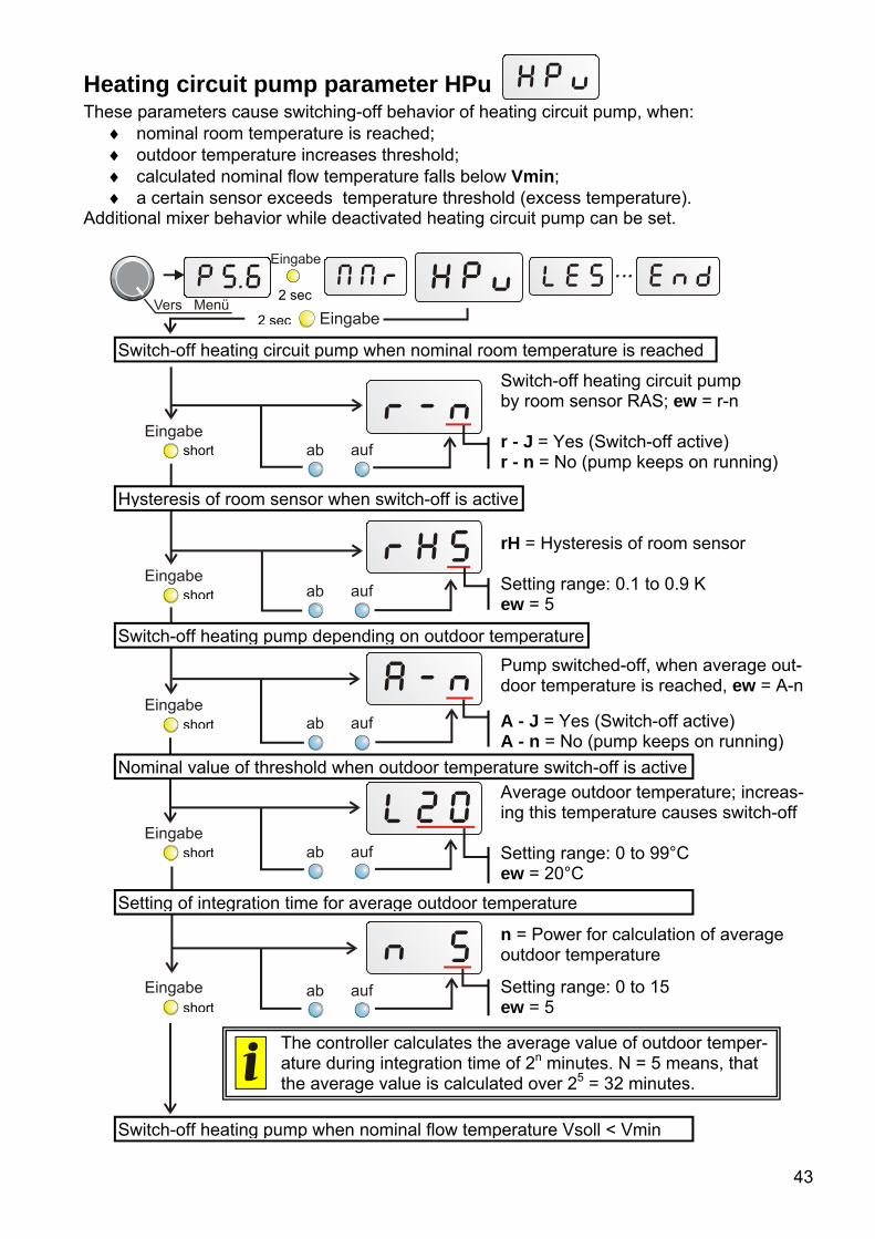
Heating circuit pump parameter HPu These parameters cause switching-off behavior of heating circuit pump, when:
nominal room temperature is reached; outdoor temperature increases threshold; calculated nominal flow temperature falls below Vmin; a certain sensor exceeds temperature threshold (excess temperature).
Additional mixer behavior while deactivated heating circuit pump can be set. Switch-off heating circuit pump by room sensor RAS; ew = r-n r - J = Yes (Switch-off active) r - n = No (pump keeps on running) rH = Hysteresis of room sensor Setting range: 0.1 to 0.9 K ew = 5 Pump switched-off, when average out-door temperature is reached, ew = A-n
A - J = Yes (Switch-off active) A - n = No (pump keeps on running)
Average outdoor temperature; increas-ing this temperature causes switch-off Setting range: 0 to 99°C ew = 20°C n = Power for calculation of average outdoor temperature
Setting range: 0 to 15 ew = 5
2 sec
2 sec
short
short
short
short
short
Switch-off heating circuit pump when nominal room temperature is reached
Hysteresis of room sensor when switch-off is active
Switch-off heating pump depending on outdoor temperature
Nominal value of threshold when outdoor temperature switch-off is active
Setting of integration time for average outdoor temperature
The controller calculates the average value of outdoor temper-ature during integration time of 2n minutes. N = 5 means, that the average value is calculated over 25 = 32 minutes.
Switch-off heating pump when nominal flow temperature Vsoll < Vmin

44
Switch-off heating circuit pump when nominal flow temperature Vsoll < Vmin; ew = S - J S - J = Yes (Switch-off active) S - n = No (pump keeps on running)
Sensor U, on which excess tempera-ture protection function works. U 0 = function deactivated ew = U 0
Setting range: U 1 – U3
Temperature threshold C; when this temperature is reached at set sensor U, heating circuit operates in normal heating mode; ew = C 90 Setting range: 0 to 99 °C Mixer behavior when heating circuit pump is switched off; ew = mS
mr = Mixer keeps on controlling mS = Mixer closes mo = Mixer opens mu = Mixer unchanged
Input loop starts again
Exit from menu happens by pressing the yellow „Eingabe“ key for 2 seconds, turning the selector switch or automatically after one minute.
Switch-off heating pump when nominal flow temperature Vsoll < Vmin
short
short
short
short
Allocation of sensor for excess temperature protection function
Temperature threshold for excess temperature protection function
Mixer behavior when heating circuit pump is switched off

45
Legionella protection function LES For avoiding production of legionellae this protection function can be activated. After lapse of cycle time (tc) tank temperature is heated up to nominal temperature (C) be-ginning from start time (h) (depending to program).
tc = cycle time for legionella protection function Setting range: 0 to 9 days ew = tc 0 h = Start time of heating up phase Setting range: 0 to 23 (11 pm) ew = h 17 (5 pm)
C = Nominal heating up temperature of tank Setting range: 0 to 99°C ew = C 70
Input loop starts again
Exit from menu happens by pressing the yellow „Eingabe“ key for 2 seconds, turning the selector switch or automatically after one minute.
2 sec
2 sec
short
short
short
Setting of cycle time
Start time of heating up phase
Setting of heating up temperature

46
2 sec
2 sec
short
short
short
Setting sensor type
Selecting next sensor
Selecting next sensor (up to F6P)
Sensor type Sen Menu Sensor type allows switch-over of sensors between Pt1000 and semi-conductor (KTY) types. Factory setting (ex works) of all sensors is Pt1000 (P).
Selected sensor (Setting range F1 to F6) P = Pt1000 H = KTY (semi-conductor) ex works = P Selected sensor (Setting range F1 to F6) P = Pt1000 H = KTY (semi-conductor) ex works = P
Input loop starts again
Exit from menu happens by pressing the yellow „Eingabe“ key for 2 seconds, turning the selector switch or automatically after one minute.

47
After-running time PnL During the start phase, the pumps may repeatedly switch on and off for a long time, espe-
cially with solar and heating systems with long hydraulic system lines. This response can be reduced by using a speed control or increasing the pump after-run time.
Depending on the selected program each output can be allocated an after-running time, except mixer outputs.
Example: After access to the sub menu PnL the display shows “t13”. That means, the pump after-running time for output 1 is 3 minutes.
t1 means after-running time for output 1 After-running times (t1 to t5) can be allocated to outputs A1 to A5 depending on program
.2 is the after-running time Setting range: .1 to .9 (10 to 90 sec) or 2 to 9 ( 2 to 9 min) ex works = 0
For programs 112 and 113 additional settings are possible in this sub menu PnL:
tc ... Cycle time, setting range: 0 to 90 min (tc0 to tc9), ew: tc 3 (30 min) tr ... Run time, setting range: 0 to 9 min (tr0 to tr9), ew: tr 2 (2 min) tb ... Blocking time, setting range: 0 to 90 min (Tb0 to tb9), ew: tb 3 (30 min)
Input loop starts again
Exit from menu happens by pressing the yellow „Eingabe“ key for 2 seconds, turning the selector switch or automatically after one minute.
2 sec
2 sec
short
short
short
Setting of pump after-running times
Setting cycle time
Setting run time
Setting blocking time
short
short

48
Switching hystereses HSt Switching hysteresis is the difference between switch-on and switch-off temperature. I.e. a
thermostat set to 70°C with 10K hysteresis switches off at 70°C and on at 60°C. Hystereses are not constant, but change with measured temperature. Setting range is be-
tween1 to 9K per 64°C. The changing according to temperature has the advantage, that different consumers resp.
tanks can be used with the same settings at same time. Thus a pool with maximum tempera-ture 30°C gets a lower hysteresis, a buffer tank with max. temperature 90°C a high one.
Each setting value of the selector switch (e.g. min1, min2, max etc.) has its own hystere-sis.
The hysteresis of the differential values diff1, diff2 refer to the colder sensor. E.g. if the colder sensor shows 64°C, the output is switched on increasing the difference diff + hystere-sis 3K and switched off decreasing the difference value diff.
H1 diff 1 H5 max H2 diff 2 H6 frost protection limit H3 min 1 H7 reserve H4 min 2
Example: H13 means hysteresis of diff1 with 3K per 64°C. All hystereses are set to 3K per 64°C ex works.
Switching between hystereses H1 to H7, allocation of hystereses to switching hystereses according to the program “3” means 3K per 64°C, setting range: 1 to 9K per 64°C ew = 3K
Input loop starts again
Exit from menu happens by pressing the yellow „Eingabe“ key for 2 seconds, turning the selector switch or automatically after one mi-nute.
2 sec
2 sec
short
short
short
Setting of hystereses
Selecting next hyste-resis (up to H7)

49
Pump speed control Pd1, Pd2
This menu allows activating and adjustment the outputs A1 and A2 for pump speed con-trol.
Decrease of flow, e.g. in a boiler, causes – because of the longer dwell time in it – an in-crease of output temperature. So it is possible to get the boiler and the tank as well to a useable temperature level in short time, but that causes a worse efficiency.
The sensor creates together with controller, pump and the hydraulic system a control loop, which makes it possible to keep the temperature at the sensor constant by speed variation. Three control functions are available; they can be activated together:
Absolute value control – Maintaining a sensor at constant temperature
Differential control - Keeps the temperature constant between two sensors
Event control - If a set temperature event occurs, the speed control starts, thus keeping a sensor constant.
Advice: Differential control and event control allow setting the temperature sensor T7. In
this case T7 means nominal flow temperature Vsoll.
Setting of pump speed control for output A1
Absolute value control
2 sec
2 sec
short
A = Absolute value control Temperature sensor, whose temperature is kept constant at the absolute value C (T1) ew = 0
Value is changeable from - 6 to 6; negative sign means inverse function => increasing temperature causes de-creasing speed. A0 = off
Setting desired temperature C

50
C = constant temperature value
Temperature in °C, sensor is kept constant at this temperature ew = 50°C F = Differential control
“1” = warmer temperature sensor T1
“3” = colder temperature sensor T3 ew = 0
d8.0 = constant kept temperature difference 8.0K between sensors T1 and T3 (“F13”) ew = 8.0K L = Event control (limiting function)
On sensor T3 operates value “b” On sensor T1 operates value “H” ew = 0
“b” = limiting temperature When sensor T3 increases 60°C sensor T1 will be kept at temperature “H”, ew = 60°C “h” = maximum value between 0 to 99°C “H” = maximum value between 100 to 199°C H30 = Maximum value 130°C for the second set sensor in position “L” (Example: Sensor 1); sensor T1 will be kept at 130°C constantly; ew = H30 (130°C)
short
short
short
short
short
short
Event control
Setting desired temperature C
Differential control
Setting differential temperature d
Limiting temperature b
Maximum value H/h
Setting proportional part
F13 = Differential control between T1 and T3. Speed increases, when temperature difference increases = Inverse characteristic F 0 = Off

51
Pr = Proportional part The speed is changed one increment per 0.8K deviation from the nominal value. A high number leads to a more stable system but also to greater devia-tion from the temperature set. Setting range: 0 to 9 = 0 to 0.9K, ew=5
In = Integral part For 1K of deviation from the nominal value, the speed is changed one incre-ment every 4 seconds. A larger number makes the system stable, but the ad-justment to the nominal value is slower. Setting range: 0 to 9 sec, ew=5 di = Differential part If the nominal value deviates at a speed of 0.5K per second, the speed is changed by one increment. Higher val-ues provide a more stable system but adjustment to the nominal value is slower. Setting range: 0 to 9 = 0 to 0.9K, we=5 u = Lower speed limit Example: Lower speed limit = 6 Necessary for avoiding pump standstill Setting range: 0 to 30, ew = 1
n = current speed stage Current speed stage = 18 n1 = lowest stage n30 = highest stage
Input loop starts again
Exit from menu happens by pressing the yellow „Eingabe“ key for 2 seconds, turning the selector switch or automatically after one minute.
short
short
short
short
short

52
Technical Data Power supply: 230V +-10%, 50- 60Hz, Power input: max. 4 VA Fuse: 3.15 a fast acting (device & output) Supply cable: 3x 1mm² H05VV-F conforming to EN 60730-1 Protection class: IP40 Allowed ambient temperature: 0 to 45°C Sensors: Pt1000, accuracy between 0 and 1000°C: +-0.35K Tank sensor BFPT1000: Diameter 6 mm, according to immersion sleeves, incl. 2 m cable
(up to 90°C continuous load) AUSPT: Outdoor sensor in mounting housing (light grey) RASPT: Room sensor with possibility of remote control and switching be-
tween operating modes Difference temperature: adjustable from 0 to 99°C (diff) Thresholds: adjustable from 0 to 150°C (min, max) Hysteresis: adjustable from 1 to 9°C per 64°C Speed control: 30 speed stages result in change of amount of max. 1:10 . Temperature display: from -50 to +199°C Resolution: from -9.9 to 100°C with 0.1°C, otherwise 1°C Accuracy: typ. 0.4 and max. +-1K in range 0 to 100°C Outputs: Triac output 1 and output 2 (minimum load of 20W required) Relay contacts outputs 3, 4 and 5 Rated current load A1, A2: 250V / 1.5 A, Rated current load A3, A4, A5: 250V / 2.5A
Quantity delivered: Controller with 6 temperature sensors (3 x BFPT1000, 1 x KFPT1000, 1 x RASPT, 1 x AUSPT1000), 3 immersion sleeves 140mm, mounting material, mains cable with plug

53
Table of settings If the control system fails unexpectedly, all of the settings should be reset for initial configura-tion. In this case, problems are inevitable if all of the setting values are entered in the follow-ing table. If there are questions, this table has to be provided. Only then is a simulation possible to reproduce the error. ew = factory setting (ex works) cs = controller settings
ew cs ew cs
Values Sensor T1 °C Output A1 Aut Sensor T2 °C Output A2 Aut Sensor T3 °C Output A5 Aut Sensor T4 °C Mixer output A3/A4 Aut Nom. flow value Vsoll °C Sensor T5 °C Program Prog. 0 Sensor T6 °C Version
Basic, heat curve and mode parameters min1 60 °C °C Modus Mod Aut min2 30 °C °C Par rAS max 70 °C °C diff1 5.0 K K diff2 5.0 K K Vmin 25 °C °C Vmax 80 °C °C T-20 70 °C °C T+20 30 °C °C Tnorm 20°C °C Tabs 15°C °C
Mixer control parameters Mr Heating circuit pump parameter HPu Mixer control mode Atr Switch-off by room
sensor r - n
Mixer run-time tL 3 min min Hysteresis room sen-sor rH
5 K
Averaging time of out-door temperature n
5 Switch-off outdoor temperature
A - n
Room influence r 50% % Nom. value outdoor temperature L
20°C °C
Increase in switch-on power Eu
0 % % Averaging time of out-door temperature n
5
Switch-off nominal flow temperature
S - J
Sensor for excess temperature protection function U
0
Temp. threshold C 90 °C °C Mixer behavior mS

54
ew cs ew csLegionella protection function LES Sensor type SEn
Cycle time tc 0 d Sensor T1 F1P Start time h 17 h h Sensor T2 F2P Nominal temperature C 70 °C °C Sensor T3 F3P Sensor T4 F4P Sensor T5 F5P Sensor T6 F6P
Pump after-running time PnL Hystereses HSt Output 1 t1 t10 Hysteresis H1 H13 Output 2 t2 t20 Hysteresis H2 H23 Output 5 t5 t50 Hysteresis H3 H33 Cycle time tc tc3 Hysteresis H4 H43 Run time tr tr2 Hysteresis H5 H53 Blocking time tb tb3 Hysteresis H6 H63
Speed control Speed control 1 Pd1 Speed control 2 Pd2
Absolute value control A 0 Absolute value control A 0 Desired value for A c50 °C Desired value for A c50 °CDifferential control F 0 Differential control F 0 Desired value for F d8.0 K Desired value for F d8.0 KLimiter function L 0 Limiter function L 0 Limit for L b60 °C Limit for L b60 °CMaximum value for L H30 °C Maximum value for L H30 °CProportional part Pr5 Proportional part Pr5 Integral part In5 Integral part In5 Differential part di5 Differential part di5 Minimum speed U 1 Minimum speed U 1
Time programs (Zeitprogr) Program P1 Program P2 Program P3 Program P4 Program P5
ON P1.1 P2.1 P3.1 P4.1 P5.1 OFF P1.2 P2.2 P3.2 P4.2 P5.2 ON P1.3 P2.3 P3.3 P4.3 P5.3 OFF P1.4 P2.4 P3.4 P4.4 P5.4 ON P1.5 P2.5 P3.5 P4.5 P5.5 OFF P1.6 P2.6 P3.6 P4.6 P5.6
Allocation of time programs to outputs and weekdays Tag ZP->A (enabled allocations of outputs are different depending to the program)
Weekday Output A1 Output A2 Output A5 Monday Mo Tuesday Di Wednesday Mi Thursday Do Friday Fr Saturday Sa Sunday So

55
Instructions for troubleshooting In general, all of the settings in the menus and the terminals should be checked if there is
an error. The most frequent errors:
Check the program number.
If an output does not switch – check, if “Aut” is set at position “Ausgang”
Check the thresholds for on/off (min/max) and the set differential temperatures (diff). Have the thermostat and differential thresholds been (resp. not been) reached?
What is changed in the sub menus?
Can the output be switched on/off in manual mode? - If endurance runs and standstill at the output produce an appropriate reaction, the unit is definitely not broken.
Are all of the sensors connected to the right terminals? - Heat the sensor using a lighter and check the display. Incorrect temperature displayed:
If a value such as -999 is displayed when a sensor short-circuits or 999 if there is an interruption, the cause may not be a material or terminal error. Are the correct sensor types (KTY or PT1000) selected under the menu SEn? The factory settings have all inputs set to P (Pt1000).
The sensor can also be checked without a measuring device simply by changing the part that is probably defective with one that works at the strip terminal and checking the dis-play. The resistance measured with an ohmmeter should have the following value accord-ing to the temperature:
Temp. [°C] 0 10 20 25 30 40 50 60 70 80 90 100R(Pt1000) [Ω] 1000 1039 1078 1097 1117 1155 1194 1232 1271 1309 1347 1385R(KTY) [Ω] 1630 1772 1922 2000 2080 2245 2417 2597 2785 2980 3182 3392
If the unit does not run when it has power, the quick-blow fuse 3.15A that protects the control system and the output should be checked and exchanged if necessary.
The settings of the menu functions ex works can be restored at any time using the yel-low key „Eingabe“ when plugging the unit in.
The settings of all the parameters and menu functions ex works can be restored at any time using both blue keys (“ab/auf”) when plugging the unit in.
As the programs are constantly being revised and improved, there may be a difference in the numbering of the sensors, pumps, and programs. Only the instruction manual provided with the device delivered applies (identical version number). The version number of the manual must correspond to the one for the device.
If the control system malfunctions despite these checks as described above, please con-tact your retailer or the manufacturer directly. The cause of the error can only be determined if the table of settings has been completely filled in along with a description of the error. If possible, also include a hydraulic diagram of the system.
Rights to make technical changes reserved ©2015

Information on the Eco-design Directive 2009/125/EC Product Class1, 2 Energy effi-
ciency3 Standby max. [W]
Power consumption typ.
[W]4
Max. power consumption [W]4
HZR655 max. 7 max. 3.5 1.3 1.06 / 2.42 1.3 / 2.8 1Definitions according to Official Journal of the European Union C 207 dated 03/07/2014 2 The classification applied is based on optimum utilisation and correct application of the products. The actual applicable class may differ from the classification applied. 3 Contribution of the temperature controller to seasonal central heating efficiency in percent, rounded to one decimal place 4 No output active = standby / all outputs and display active 5 The class is defined on the basis of the programming of the heating circuit controller, in accordance with the Ecodesign Directive.

EU Declaration of conformity
Document- Nr. / Date: TA17009 / 02/02/2017
Company / Manufacturer: Technische Alternative RT GmbH
Address: A- 3872 Amaliendorf, Langestraße 124
This declaration of conformity is issued under the sole responsibility of the manufacturer.
Product name: HZR65
Product brand: Technische Alternative RT GmbH
Product description: Universal heating controller
The object of the declaration described above is in conformity with Directives:
2014/35/EU Low voltage standard
2014/30/EU Electromagnetic compatibility
2011/65/EU RoHS Restriction of the use of certain hazardous substances
2009/125/EC Eco-design directive
Employed standards:
EN 60730-1: 2011 Automatic electrical controls for household and similar use – Part 1: General requirements
EN 61000-6-3: 2007 +A1: 2011 + AC2012
Electromagnetic compatibility (EMC) - Part 6-3: Generic standards - Emission standard for residential, commercial and light-industrial environments
EN 61000-6-2: 2005 + AC2005
Electromagnetic compatibility (EMC) - Part 6-2: Generic standards - Immunity for industrial environments
EN 50581: 2012 Technical documentation for the assessment of electrical and electronic products with respect to the restriction of hazardous substances
Position of CE - label: On packaging, manual and type label
Issuer: Technische Alternative RT GmbH A- 3872 Amaliendorf, Langestraße 124
This declaration is submitted by
Dipl.-Ing. Andreas Schneider, General manager, 02/02/2017
This declaration certifies the agreement with the named standards, contains however no warranty of characteristics.
The security advices of included product documents are to be considered.


Guarantee conditions Note: The following guarantee conditions do not in any way limit the legal right to a guaran-tee, rather expand your rights as a consumer.
1. The company Technische Alternative RT GmbH provides a two-year guarantee from the date of purchase by the end consumer for all the devices and parts which it sells. Defects must be reported immediately upon detection and within the guarantee period. Technical support knows the correct solution for nearly all problems. In this respect, contacting us immediately will help to avoid unnecessary expense or effort in troubleshooting.
2. The guarantee includes the free of charge repair (but not the cost of on site fault-finding, re-
moval, refitting and shipping) of operational and material defects which impair operation. In the event that a repair is not, for reasons of cost, worthwhile according to the assessment of Technische Alternative, the goods will be replaced.
3. Not included is damage resulting from the effects of overvoltage or abnormal ambient condi-
tions. Likewise, no guarantee liability can be accepted if the device defect is due to: transport damage for which we are not responsible, incorrect installation and assembly, incorrect use, non-observance of operating and installation instructions or incorrect maintenance.
4. The guarantee claim will expire if repairs or actions are carried out by persons who are not au-thorised to do so or have not been so authorised by us or if our devices are operated with spare, supplementary or accessory parts which are not considered to be original parts.
5. The defective parts must be sent to our factory with an enclosed copy of the proof of purchase
and a precise description of the defect. Processing is accelerated if an RMA number is applied for via our home page www.ta.co.at. A prior clarification of the defect with our technical sup-port is necessary.
6. Services provided under guarantee result neither in an extension of the guarantee period nor
in a resetting of the guarantee period. The guarantee period for fitted parts ends with the guarantee period of the whole device.
7. Extended or other claims, especially those for compensation for damage other than to the de-
vice itself are, insofar as a liability is not legally required, excluded.
Legal notice These assembly and operating instructions are protected by copyright. Use outside the copyright requires the consent of the company Technische Alternative RT GmbH. This applies in particular to reproductions, translations and electronic media.
Technische Alternative RT GmbH A-3872 Amaliendorf Langestraße 124 Tel ++43 (0)2862 53635 Fax ++43 (0)2862 53635 7E-Mail: [email protected] --- www.ta.co.at --- © 2017