Topology of serial and parallel manipulators and topological diagrams
31
Topology of serial and parallel manipulators and topological diagrams Xiaoyu WANG, Luc BARON ∗ and Guy CLOUTIER Ecole Polytechnique of Montreal, Department of Mechanical Engineering C.P. 6079, succ. Centre-Ville, Montreal, QC, CANADA, H3C 3A7 Abstract This paper deals with manipulator topology. The term topology was first intro- duced into robotics to characterize the kinematic structure of a manipulator with- out reference to its dimensions. Its dimension-independent aspect does not pose a considerable problem to planar manipulators, but makes it no longer appropriate to describe spatial manipulators especially spatial parallel manipulators, because such important properties as the degree of freedom of a manipulator and the de- gree of mobility of its end-effector as well as the nature of the mobility are highly dependent on some dimensional elements. In order to address this fundamental is- sue in kinematic synthesis, we introduced essential constraints into the concept of topology through the analysis of representative architectures, proposed a topological representation which provides a better correspondance between the representation and the intended manipulators, a necessity for topological synthesis and documen- tation. Introducing the essential constraints can also improve the efficiency of some synthesis methods. Key words: Manipulator; Topology; Geometry; Representation; Diagram Preprint submitted to Elsevier Science 22 March 2007 Manuscript
Transcript of Topology of serial and parallel manipulators and topological diagrams

Topology of serial and parallel manipulators
and topological diagrams �
Xiaoyu WANG, Luc BARON ∗ and Guy CLOUTIER
Ecole Polytechnique of Montreal, Department of Mechanical Engineering
C.P. 6079, succ. Centre-Ville, Montreal, QC, CANADA, H3C 3A7
Abstract
This paper deals with manipulator topology. The term topology was first intro-
duced into robotics to characterize the kinematic structure of a manipulator with-
out reference to its dimensions. Its dimension-independent aspect does not pose a
considerable problem to planar manipulators, but makes it no longer appropriate
to describe spatial manipulators especially spatial parallel manipulators, because
such important properties as the degree of freedom of a manipulator and the de-
gree of mobility of its end-effector as well as the nature of the mobility are highly
dependent on some dimensional elements. In order to address this fundamental is-
sue in kinematic synthesis, we introduced essential constraints into the concept of
topology through the analysis of representative architectures, proposed a topological
representation which provides a better correspondance between the representation
and the intended manipulators, a necessity for topological synthesis and documen-
tation. Introducing the essential constraints can also improve the efficiency of some
synthesis methods.
Key words: Manipulator; Topology; Geometry; Representation; Diagram
Preprint submitted to Elsevier Science 22 March 2007
Manuscript

1 Introduction
As far as the kinematics is concerned, a mechanism is a kinematic chain with
one of its links designated as the base and another as the end-effector. A ma-
nipulator is a mechanism with all or some of its joints actuated. Driven by the
actuated joints, the end-effector and all links undergo constrained motions
with respect to the base [1]. A parallel manipulator is a mechanism whose
end-effector is connected to its base by at least two independent kinematic
chains [2]. The early works in the manipulator research mostly dealt with a
particular design; each design was described in a particular way. With the
number of designs increasing, the consistency, preciseness and conciseness of
topological description of manipulators become more and more problematic.
To describe how a manipulator is kinematically constructed, no normalized
term and definition have been proposed. The words architecture [3], struc-
ture [4], topology [5], and type [6,7] all found their way into the literature,
describing kinematic chains without reference to dimensions. However, the
kinematic properties of spatial manipulators are highly sensitive to some di-
mensional elements. The problem is that with the original definition of the
term topology (the term topology is preferred here to other terms), manipu-
lators of the same topology are often too different to even be classified in the
same category. It is therefore necessary to take into account some dimensional
elements when dealing with topology.
Words used to define kinematic details are equally diverse. Parameter [8], di-
mension [9,10] and geometry [11] are among the terms used to this end. As
� Submitted to Mechanism and Machine Theory.∗ Corresponding author. Tel.: +1-514-340-4711 poste 4744; Fax:+1-514-340-5867
Email address: [email protected] (Luc BARON).
2

for the kinematic representation of parallel manipulators, one can hardly find
a method which is adequate for a wide range of manipulators and commonly
accepted and used in the literature. However, in the classification [12,13], com-
parison studies [14,15] (equivalence, isomorphism, similarity, difference, etc.)
and manipulator kinematic synthesis, an effective kinematic representation is
essential.
This work is aimed at identifying and introducing essential geometry elements
into topology and proposing a new topological representation accordingly. The
representation should work appropriately for most of the manipulators and be
as precise and concise as possible. It should also be adaptable to facilitate
automatic kinematic synthesis. The rest of this paper is organized as follows.
In Section 2, some basic concepts and definitions are presented, the impor-
tance of geometric constraints in determining the basic kinematic properties
are discussed. The concepts of kinematic composition, essential constraints,
topology, and geometry are introduced in Section 3. In Section 4, the kine-
matic representations are reviewed and their limitations identified. Based on
the review and the analysis of geometric constraints, a topological diagram is
proposed. Topological diagrams of representative manipulators are presented
in Section 5. How the efficiency of kinematic synthesis can be improved by
introducing essential constraints is discussed in Section 6.
2 Preliminary
Some basic concepts and definitions about kinematic chains are necessary to
review as a starting point of our discussion on topology and topological repre-
sentation. A kinematic chain is a set of rigid bodies, also called links, coupled
3

Fig. 1. Lower Kinematic Pairs
Prismatic (P)
Revolute (R)
Spherical (S)
Cylindrical (C)
Helical (H)
Planar (E)
by kinematic pairs. A kinematic pair is, then, the coupling of two rigid bod-
ies so as to constrain their relative motion. We distinguish upper pairs and
lower pairs. An upper kinematic pair constrains two rigid bodies such that
they keep a line or point contact; a lower kinematic pair constrains two rigid
bodies such that a surface contact is maintained [16]. A joint is a particular
mechanical implementation of a kinematic pair [17]. As shown in Fig. 1, there
are six types of joints corresponding to the lower kinematic pairs - spheri-
cal (S), cylindrical (C), planar (E), helical (H), revolute (R) and prismatic
(P) [18]. Since all these joints can be obtained by combining the revolute and
prismatic ones, it is possible to deal only with revolute and prismatic joints
in kinematic modeling. Moreover, all these joints can be represented by el-
ementary geometric elements, i.e., point and line. To characterize links, the
notions of simple link, binary link, ternary link, quaternary link and
4
n-link were introduced to indicate how many other links is connected to a
link. Similarly, binary joint, ternary joint and n-joint indicate how many
links are connected to a joint. A similar notion is the connectivity of a link
or a joint [19]. These basic concepts constitute a basis for kinematic analysis
and kinematic synthesis.
For kinematic analysis, the kinematic description of a mechanism includes
basic information and parameters. The basic information is which link is con-
nected to which other links by what types of joints. This basic information is
referred to as structure, architecture, topology, or type, respectively, by different
authors. This basic information alone is of little interest, because the kinematic
properties of the corresponding mechanisms can vary too much to characterize
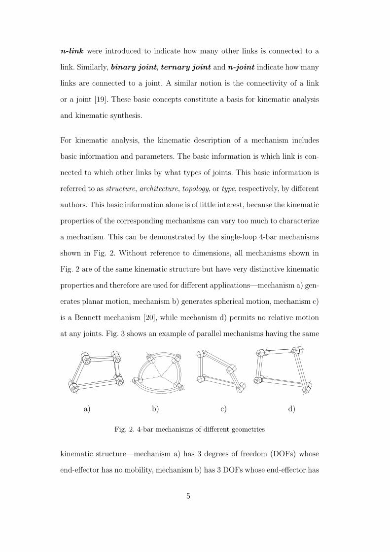
a mechanism. This can be demonstrated by the single-loop 4-bar mechanisms
shown in Fig. 2. Without reference to dimensions, all mechanisms shown in
Fig. 2 are of the same kinematic structure but have very distinctive kinematic
properties and therefore are used for different applications—mechanism a) gen-
erates planar motion, mechanism b) generates spherical motion, mechanism c)
is a Bennett mechanism [20], while mechanism d) permits no relative motion
at any joints. Fig. 3 shows an example of parallel mechanisms having the same
a) b) c) d)
Fig. 2. 4-bar mechanisms of different geometries
kinematic structure—mechanism a) has 3 degrees of freedom (DOFs) whose
end-effector has no mobility, mechanism b) has 3 DOFs whose end-effector has
5

3 degrees of mobility (DOMs) in translation, mechanism c) permits no relative
motion at any joints. A particular mechanism is thus described, in addition
a) b) c)
Fig. 3. 3-PRRR parallel mechanisms
to the basic information, by a set of parameters which define the relative po-
sition and orientation of each joint with respect to its neighbors. For complex
closed-loop mechanisms, an often ignored problem is that certain parameters
must take particular values in order for the mechanism to be functional and
have the intended kinematic properties. More attention should be payed to
these parameters which play a qualitative role in determining some important
kinematic properties of the mechanism.
For kinematic synthesis, not only do the eligible mechanisms have particular
kinematic structures, but also they feature some particular relative positions
and orientations between certain joints. If this particularity is not taken into
account when formulating the synthesis model, a great number of mechanisms
generated with the model will not have the required kinematic properties and
have to be discarded.
In the next section, we investigate the special joint dispositions and give a
new definition of the term topology by introducing the essential constraints.
6

3 Topology
Since the 1960s, a very large number of manipulator designs have been pro-
posed in the literature or disclosed in patent files. The kinematic properties
of these designs were studied mostly on a case by case basis; characteristics of
their kinematic structure were often not investigated explicitly; the constraints
on the relative joint locations which are essential for a manipulator to meet
the kinematic requirements were rarely put into the kinematic representation.
Constraints are introduced mainly to meet the functional requirements, to sim-
plify the kinematic model, to optimize the kinematic performances, or from
manufacturing considerations. These constraints can be revealed by investi-
gating the underlying design ideas.
For a serial manipulator to generate planar motion, all its revolute joints
need to be parallel and all its prismatic joints should be perpendicular to the
revolute joints. For a serial manipulator to generate spherical motion, the axes
of all its revolute joints must be concurrent [21]. For a parallel manipulator
with three identical legs to produce only translational motion, the revolute
joints of the same leg must be arranged in one or two directions [22].
A typical example of simplifying the kinematic model is the decoupling of the
position and orientation of the end-effector of a 6-joint serial manipulator.
This is realized by having three consecutive revolute joint axes concurrent. A
comprehensive study was presented in [23] on the inverse kinematic solutions
of 6-joint serial manipulators. The study reveals how the inverse kinematic
problem is simplified by making joint axes parallel, perpendicular or intersect.
7

Optimizing the kinematic performance also gives rise to special relative joint
locations. Isotropic parallel manipulators having orthogonal actuated joint
axes proposed in [24] and [25] are examples of this kind. In summary, these
special constraints are the special relative joint locations, i.e. parallelism, per-
pendicularity, intersection, coplanarity, etc.
To facilitate the kinematic analysis, kinematic synthesis, classification and
comparison studies of manipulators, the terms kinematic composition, essen-
tial constraint, topology, geometry and their definitions are proposed as fol-
lows:
• the kinematic composition of a manipulator is the essential information
about the number of its links, which link is connected to which other links
by what types of joints and which joints are actuated;
• the essential constraints are the minimum conditions for a manipulator
of given kinematic composition to have the required DOF and DOM;
• the topology of a manipulator is its kinematic composition plus the essen-
tial constraints;
• The geometry of a manipulator is a set of constraints on the relative
locations of its joints which are unique to each of the manipulators of the
same topology.
Hence, topology also has a geometrical aspect such as parallelism, perpendic-
ularity, coplanar, and even numerical values and functions on the relative joint
locations which used to be considered as geometry. By our definition, geometry
no longer includes relative joint locations which are common to all manipu-
lators of the same topology because the later are the essential constraints
and belong to the topology category. A manipulator can thus be much better
8

characterized by its topology.
4 Topological diagrams
4.1 Topological representation review
The basic notions about link and joint introduced in Section 2 were used to
describe manipulator kinematics. With these notions, the general spatial ar-
rangement of links and joints of a manipulator can be described with ease.
For example, the kinematic chain associated with a serial manipulator is con-
structed with binary links, two simple links and binary joints; while that asso-
ciated with a parallel manipulator is composed of binary links, two multiple-
links and binary joints. The limitation of such description is obvious since the
Fig. 4. Kinematic joint symbols [26]
(a) Revolute
(b) Prismatic
(c) Cylindrical
(d) Spherical
information about the joint types and which joints are actuated can not be
provided without lengthy notations. Alphanumeric representation, 3-UPU or
3-RRR for example, may be the most effective one for kinematic composition,
which was widely used in the literature. In general, the number indicates the
9

RepresentationJoint name
Passive joint Actuated joint
Revolute
Prismatic P
RR
P
Fig. 5. Layout graph symbols [29]
0 1 22R7
R2
R3 3
64 5R5R1
R 6
R 4
Fig. 6. Layout graph symbols [19]
number of identical kinematic chains, the sequence of upper case letters indi-
cates the joint types along the kinematic chain and the actuated joint is iden-
tified by an underline. One of the more visual representation methods is the
kinematic diagram. A kinematic diagram is a drawing of a mechanism show-
ing its essential elements in simplified form with graphical symbols (Fig. 4).
Although a great deal of effort has been made to normalize the graphical
symbols for kinematic diagrams [27] [26] [28], the practice in the literature
is just far from normalized. Similar to the kinematic diagram, the kinematic
layout graph (Fig. 5) was proposed in [29]. With the kinematic layout graph,
each joint is represented by an uppercase letter indicating the joint type sur-
rounded by a rectangle; joints carried by the same link are connected by a
line. The kinematic layout graph or its variants (Fig. 6) can be found in a
number of recent publications. The common problem with the above kine-
matic representations is the poor correspondence between the representation
and the intended manipulators. One kinematic diagram or layout graph may
correspond to many manipulators with quite different kinematic properties.
10

For planar mechanisms, there exist three similar representations, i.e., struc-
Fig. 7. Structural schema, graph, and functional schema
(a) Structural schema (b) Graph
(c) Functional schema
tural schema, graph, and functional schema (Fig. 7). The graph representation
proposed in [30] [31] is based on an abstract kinematic representation similar
to the symbolic representation of chemical compound. With graph representa-
tion, the vertices denote links while edges denote joints. To distinguish differ-
ent joints, the edges can be labeled or numbered. Since a graph can be easily
represented by matrices, automatic synthesis algorithms can be implemented
and kinematic chains can be systematically enumerated using graph theory
and combinatorial analysis. When used with spatial mechanisms, the graph
representation suffers from the same drawbacks as the kinematic diagram and
the kinematic layout graph. For spatial manipulators, joint and link locations
are often so complex that perspective views and section views have to be used
to represent the kinematic chains. Although the perspective views and section
views are simplified as much as possible, the special features of the joint loca-
tions, parallelism and perpendicularity for example, can hardly be recognized
by anyone not familiar with spatial mechanism. The topology features and ge-
ometry features can not be distinguished without complementary notations.
11

A new representation of layout graph with graphical symbols for geometric
constraints was proposed in [32]. Only one example of this representation was
given, whether it is suitable for a wide range of manipulators remains to be
seen. Denavit-Hartenberg notation [8] and the initial configuration matrix [22]
were used for implicit topological representation when emphasis was put on
geometric synthesis and visual representation could be compromised. In sum-
mary, the existing kinematic representations are only suitable for kinematic
composition or kinematic geometry. There is a lack of topological representa-
tion.
4.2 Kinematic composition
Taking the basic ideas of graph and layout graph, we propose that the kine-
matic composition be represented by a diagram having the graph structure
so as to be eventually adapted for automatic synthesis. The joint type is des-
ignated as an upper case letter, i.e., R for revolute, P for prismatic, H for
helical, C for cylindrical, S for spherical and E for planar. Actuated joints are
identified by a line under the corresponding joint. The letters denoting joint
types are placed at the vertices of the diagram, while the links are represented
by edges. But there is a problem for non serial mechanisms. If a link carries
more than two joints, then this link corresponds to more than one edge. From
the diagram, edges corresponding to one link can not be identified and the fact
that no motion is permitted between them is not reflected. A simple way to
solve this problem, while keeping the graph structure, is the use of an arrow at
the edge end. Each joint has two joint elements, to which element a link is con-
nected is indicated by the presence or absence of the arrow. Any link connected
12

a) Physical manipulator b) Diagram
Fig. 8. Kinematic Composition of a Planar 3-RRR parallel manipulator
a) Physical manipulator b) Diagram
Fig. 9. Kinematic Composition of a Spherical 3-RRR parallel manipulator
to the same joint element is actually rigidly attached and no relative motion
is possible. “→R→R→R→” is a serial mechanism while “→R↔R↔R←” or
“—R—R—R—” is a single link having three revolute joints. In this way, the
diagram always has a graph structure. The kinematic composition of a planar
parallel manipulator is shown in Fig. 8. The most left column represents the
base carrying three actuated revolute joints while the most right column the
end-effector. The end-effector is connected to the base by three identical kine-
matic chains composed of three revolute joints respectively. It is noteworthy
that a very different manipulator shown in Fig. 9 has exactly the same kine-
matic composition. The diagram must bear additional information in order to
appropriately represent the topology.
13

4.3 Essential constraints
Essential constraints are the relative locations between lines. Constraints on
relative joint axis locations can be summarized as the following six and only
six possible situations:
Joint axes are not parallel and do not intersect;
Joint axes are parallel and do not intersect;
Joint axes are perpendicular and do not intersect;
Joint axes intersect at an arbitrary angle;
Joint axes intersect at zero angle or aligned;
Joint axes intersect at right angle.
Fig. 10. Graphic symbols for essential constraints
Superimposing the essential constraint symbols on the kinematic composition
diagrams shown in Fig. 8 and 9, we get the diagrams shown in Fig. 11 and
12. We can see that the topology of the planar parallel manipulator is fully
represented by the diagram. The diagram shown in Fig. 13 still does not reflect
the fact that two joint axes intersect the third joint axis at the same point.
Fig. 11. Diagram of a planar parallel manipulator with essential constraints on the
relative joint locations
14

Fig. 12. Diagram of a spherical parallel manipulator with essential constraints on
relative joint locations
In order to characterize the relative situations of non-adjacent joint axes, we
introduce subscripts and superscripts into the diagram. Axes of the joints with
the same subscript are concurrent while those with the same superscript are
parallel.
Fig. 13. Diagram of a spherical parallel manipulator with constraints on relative
non-adjacent joint Locations
a) Physical manipulator b) Topological diagram
Fig. 14. Diagram of 3-UPU
Fig. 13 and 14 show diagrams with subscripts and superscripts.
15

Coplanar
Concurrent
Intersect at equal angle
Axes (points) forming the edges (vertices) of an equilateral polygon
Equal link length
Fig. 15. Constraint complex symbols
4.4 Simplified diagram
For the purpose of representing mechanisms of a subtopology, complex con-
straints are introduced and expressed by constraint vertices. A constraint ver-
tex is indicated by a rectangle. Inside the rectangle, either a meaningful symbol
or a notation index can be placed. Some symbols are proposed as shown in
Fig. 15. An example is shown in Fig. 16.
a) Physical manipulator b) Diagram of a subtopology
Fig. 16. Diagram with Constraint Vertices
Some special constraints on relative locations of revolute joints can be found
in a large number of manipulator designs, introducing the following com-
plex joints can greatly simplify their representations. These complex joints
are shown in Fig. 17, where the PI joint is proposed by Angeles [33]. Two
examples are shown in Fig. 18 and Fig. 19.
16

Two consecutive parallel revolute joints
Three parallel revolute joints
PI joint
Tow revolute joints with general relative location
Two intersecting revolute joints
Two revolute joints intersecting at right angle
Tree concurrent revolute joints
Universal joint
Fig. 17. Complex Joints
a) Physical manipulator b) Diagram
Fig. 18. Diagram of Delta [34]
Fig. 19. Diagram of parallel manipulator proposed by [35]
4.5 Topological diagram
The diagram containing information on both the kinematic composition and
the essential constraints is referred to as topological diagram. A summary
17
of topological diagram is given in the following paragraphs.
A topological diagram has vertices and edges. There are joint vertices and
constraint vertices. Joint vertices are marked by an upper case letter or a
circled graphic symbol denoting a joint, while constraint vertices are indicated
by a rectangle denoting special constraints on joints connected to it. Edges
connecting joint vertices denote links. The leftmost edge corresponds to the
base while the rightmost edge to the end-effector. Links have two kinds of
extremities, i.e. with an arrow and without arrow. Links connected to the
same joint element of a joint have the same kind of extremities pointing to this
joint, they are rigidly attached. The ways to indicate the essential constraints
are:
(1) superimpose graphical symbols on edges;
(2) add subscripts to joint vertices to indicate the concurrent joint axes;
(3) add superscripts to joint vertices to indicate which joints are parallel;
(4) add constraint vertices.
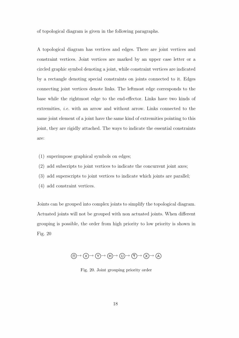
Joints can be grouped into complex joints to simplify the topological diagram.
Actuated joints will not be grouped with non actuated joints. When different
grouping is possible, the order from high priority to low priority is shown in
Fig. 20
→ → → → → → →
Fig. 20. Joint grouping priority order
18
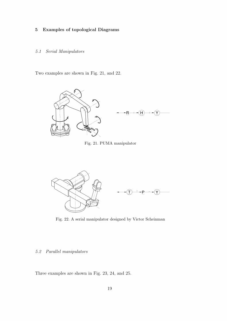
5 Examples of topological Diagrams
5.1 Serial Manipulators
Two examples are shown in Fig. 21, and 22.
Fig. 21. PUMA manipulator
Fig. 22. A serial manipulator designed by Victor Scheinman
5.2 Parallel manipulators
Three examples are shown in Fig. 23, 24, and 25.
19

Fig. 23. 4-DOF Flight Simulator by Koevermans W.P. et al.
Fig. 24. 5-DOF by Hesselbach J. et al.
Fig. 25. 6-DOF Decoupled Manipulator by Nabla, drawing by Merlet J.P
6 Kinematic synthesis methodology
There exist three major synthesis approaches for spatial manipulators. The
first one consists of three steps:
20

: all design space : eligible design space
: searched design space
Fig. 26. Illustration of design spaces
(1) Determine the possible kinematic compositions;
(2) For each kinematic composition, a parametrization is performed;
(3) With some of the parameters as design variables, the search for suitable
designs is performed.
The choice of the design variables is usually done by resorting to experience
and intuition. As shown in Section 2, given a kinematic composition, particular
geometric constraints must be satisfied in order for the manipulator to have
required kinematic properties. This approach inevitably suffers from the poor
correspondance between the suitable design space and the searched design
space (illustrated in Fig. 26). With the second approach, synthesis based on
screw theory or instantaneous kinematics for instance, the synthesis model
is formulated as implicit functions with joint types and link geometries as
unknowns. It is obvious that the synthesis can not be performed without
the implication of all link geometries, making it not suitable for qualitative
synthesis. The third approach is based on group theory. This approach is
limited to kinematic chains whose displacements form a Lie group.
The systematic analysis of the essential constraints can improve these synthe-
sis approaches. Since the essential constraints are relative locations between
21
lines or between points and lines, they can be easily formulated into the kine-
matic model. Only parameters which are not under the essential constraints
are taken as design variables, a good correspondance between the intended
manipulators and the synthesis model can therefore be achieved. With the
kinematic compositions and essential constraints, qualitative synthesis can be
performed.
6.1 Numerical topological representation
To implement geometric and topological synthesis algorithms the topology
of a serial kinematic chain composed of only revolute and prismatic joints is
represented by 6 integers, i.e.
• n: number of joints.
• x0: kinematic composition. Its bits 0 to n−1 represent respectively the joint
type of joints 1 to n with 1 for revolute and 0 for prismatic.
• x1: bits 0 to n− 2 indicate respectively whether the axes of joints 2 to n− 1
intersect the immediate preceding joint axis.
• x2: each two consecutive bits characterize the orientation of the correspond-
ing joint relative to the immediate preceding joint with 00 for parallel, 01
for perpendicular, and 10 for the general case.
• x3: supplementary constraint identifying joints whose axes are concurrent.
All joint axes whose corresponding bits are set to 1 are concurrent.
• x4: supplementary constraint identifying joints whose axes are parallel. All
joint axes whose corresponding bits are set to 1 are parallel.
22

With this numerical representation, topological constraint can be imposed on
a general kinematic model to carry out geometric synthesis to ensure that the
search is performed in designs with the intended motion type. The binary form
makes the representation very compact. No serial kinematic chain should have
more than 3 prismatic joints, so all values for x0 of 6 joint kinematic chains
take only 42B (byte) storage. Those for x1 take 31B while those for x2 243B.
Without supplementary constraints which are applied between non adjacent
joints, the maximum number of topologies is 316386 (some topologies, those
with two consecutive parallel prismatic joints for example, will not be consid-
ered for topological synthesis purpose). All topologies without supplementary
constraint can be stored in a list, making the walk through quite straight-
forward. Applying supplementary constraints while walking through the list
provides a systematic way for topological synthesis. In the following sections,
the main steps to search for geometries and topologies of parallel manipulators
with certain characteristics are presented.
6.2 Isotropic design of translational parallel manipulators of a given topology
Parallel manipulators (PM) composed of three identical sub-chains of the fol-
lowing topology can be a translational PM. [36,15,37].
Fig. 27. A sub-chain topology of translational parallel manipulators
The numerical topological representation of this sub-chain is
• n = 5.
• x0 = 111112.
23

• x1 = 01012.
• x2 = 000100012.
• x3 = 110012.
• x4 = 000002.
Under these explicit constraints, the geometries of the PM can be generated.
Applying stochastic search method, similar results as presented in [25] are
obtained. An interesting geometry with continuous isotropic configurations is
shown in Fig. 28
Fig. 28. PM with isotropic continuum
6.3 Topological synthesis examples
The motion of the end-effector (EE) is characterized in its displacement tan-
gent space. The motion type is then the structure of this space. If this space
is represented by range(GE) where GE is a 6×n matrix with n as the degree
of freedom of the EE, then the motion type can be characterized by the ranks
of the upper three rows (GEU) and the lower three rows (GEL) of GE. Let
range(Gi) represent the EE motion under the constraints of the ith sub-chain,
then
range(GE) = range(G1)⋂
range(G2)⋂ · · ·⋂ range(Gn) (1)
24

Given the motion type of the EE, range(Gi) can be derived by using either
Eq. (1) or the methods presented in [36–38]. The synthesis problem is then
transformed into the search for appropriate sub-chain topologies which is done
by walking through the topology list and applying supplementary constraints.
Fig. (29) to Fig. (32) show some examples. From the best knowledge of the
authors, the topologies shown in Fig. (29) to Fig. (30) are new topologies.
Fig. 29. 2-DOF translational PM
Fig. 30. PM with 1 DOF in translation and 3 DOF in rotation
Fig. 31. Spherical PM
25

x
y
z
Fig. 32. Spherical PM
7 Conclusion
By introducing essential geometric constraints, kinematic chains of serial and
parallel manipulators can be better characterized. This is essential for both
topology synthesis and geometry synthesis. On the one hand, topology syn-
thesis of spatial manipulator is no longer dimension-independent; most of the
topology syntheses are actually the search for some special geometric con-
straints which play a key role in determining the fundamental kinematic
properties. On the other hand, it is necessary to identify the essential con-
straints when performing geometry synthesis in order for the design space
to correspond appropriately to the intended topology. The proposed topolog-
ical diagram is comprehensive which enables the kinematic composition to
be described precisely, essential constraints to be reflected appropriately and
the elements of geometry to be isolated completely from the topological rep-
resentation. The graph structure makes it possible to implement computer
algorithms in order to perform systematic enumeration, comparison and clas-
sification of serial and parallel manipulators. The topological diagram is also
a useful tool for manual or automatic synthesis. It is highly flexible and can
be extended with ease by introducing new joint or constraint symbols.
26

Acknowledgment
The authors acknowledge the financial support of NSERC (National Science
and Engineering Research Council of Canada) under grants OGPIN-203618
and RGPIN-138478.
References
[1] L.-W. Tsai, Mechanism design: enumeration of kinematic structures according
to function, Mechanical engineering series: CRC mechanical engineering series,
CRC Press, 2001.
[2] J.-P. Merlet, Les robots paralleles, Hermes, Paris, c1997.
[3] K. H. Hunt, Geometry of robotics devices, Mechanical Engineering Transactions
7 (4) (1982) 213–220, record Number: 2700 1982.
[4] K. H. Hunt, Structural kinematics of in parallel actuated robot arms, 1982,
record Number: 2710 Proceedings Title: Design and Production Engineering
Technical Conference Place of Meeting: Washington.
[5] I. Powell, The kinematic analysis and simulation of the parallel topology
manipulator, Marconi Rev. (UK) 45 (226) (1982) 121 – 38.
[6] F. Freudenstein, E. Maki, On a theory for the type synthesis of mechanism, in:
Proceedings of the 11th International Congress of Applied Mechanics, Springer,
Berlin, 1965, pp. 420–428.
[7] D. Yang, T. Lee, Feasibility study of a platform type of robotic manipulator
from a kinematic viewpoint, Journal of Mechanisms, Transmissions and
Automation in Design 106 (1984) 191–198.
27

[8] J. Denavit, R. S. Hartenberg, Kinematic notation for lower-pair mechanisms
based on matrices, in: American Society of Mechanical Engineers (ASME), 1954.
[9] P. Chen, B. Roth, A unified theory for finitely and infinitesimally seperated
position problems of kinematic synthesis, ASME Journal of Engineering for
Industry, Series B 91 (1969) 203–208, record Number: 2800.
[10] P. Chedmail, Optimization of multi-dof mechanisms, in: J. Angeles,
E. Zakhariev (Eds.), Computational Methods in Mechanisms System, Springer
Verlag, 1998, pp. 97–130.
[11] F. C. Park, J. E. Bobrow, Geometric optimization algorithms for robot
kinematic design, Journal of Robotic Systems 12 (6) (1995) 453 – 463.
[12] T. Balkan, M. Kemal Ozgoren, M. Sahir Arikan, H. Murat Baykurt, A kinematic
structure-based classification and compact kinematic equations for six-dof
industrial robotic manipulators, Mechanism and Machine Theory 36 (7) (2001)
817 – 832.
[13] H. Su, C. Collins, J. McCarthy, Classification of rrss linkages, Mechanism and
Machine Theory 37 (11) (2002) 1413 – 1433.
[14] C. M. Gosselin, R. Ricard, M. A. Nahon, Comparison of architectures of
parallel mechanisms for workspace and kinematic properties, American Society
of Mechanical Engineers, Design Engineering Division (Publication) DE 82 (1)
(1995) 951 – 958.
[15] L.-W. Tsai, S. Joshi, Comparison study of architectures of four 3 degree-of-
freedom translational parallel manipulators, Proceedings - IEEE International
Conference on Robotics and Automation 2 (2001) 1283 – 1288.
[16] J. Angeles, Fundamentals of robotic mechanical systems : theory, methods, and
algorithms, 2nd Edition, Mechanical engineering series: Mechanical engineering
series (Springer), Springer, New York, c2003.
28

[17] IFToMM, Iftomm terminology, Mechanism and Machine Theory 38 (2003) 913–
912.
[18] J. Angeles, Spatial Kinematic Chains. Analysis, Synthesis, Optimization,
Springer-Verlag, Berlin, 1982.
[19] L. Baron, Contributions to the estimation of rigid-body motion under sensor
redundancy, Ph.D. thesis, McGill University (c1997).
[20] G. Bennett, A new mechanism, Engineering.
[21] J. M. McCarthy, An Introduction to Theoretical Kinematics, The MIT Press,
Cambridge, Massachusetts, London, England, 1990.
[22] X. Wang, L. Baron, G. Cloutier, Design manifold of translational parallel
manipulators, in: l’Agence spatiale canadienne (Ed.), Proceedings of 2003
CCToMM Symposium on Mechanisms, Machines, and Mechatronics, Montreal,
Quebec, Canada, 2003, pp. 231–239.
[23] M. Ozgoren, Topological analysis of 6-joint serial manipulators and their inverse
kinematic solutions, Mechanism and Machine Theory 37 (5) (2002) 511 – 547.
[24] P. Wenger, D. Chablat, Kinematic analysis of a new parallel machine tool: The
orthoglide, in: J. Lenarcic, V. Parenti-Castelli (Eds.), Recent Advances in Robot
Kinematics, Kluwer Academic Publishers, 2000, pp. 305– 314.
[25] X. Wang, L. Baron, G. Cloutier, Kinematic modelling and isotropic conditions of
a family of translational parallel manipulators, IEEE International Conference
on Control and Automation (2003) 173 – 177.
[26] ISO, Kinematic diagrams - graphical symbols, ISO 3952-1, 1981 (1981).
[27] R. Smith, Diagrams of kinematics, Engineer, 1886.
[28] The Association of German Engineers, Symbols for the kinematic structure
description of industrial robots, Guideline 2681 (1993).
29

[29] F. Pierrot, Robots pleinement paralleles legers: Conception, modelisation et
commande, Ph.D. thesis, Universite Montpellier II, Montpellier, France (1991).
[30] F. Crossley, Contribution to gruebler’s theory in number synthesis of plane
mechanisms, American Society of Mechanical Engineers – Papers (1962) 5 –.
[31] F. Crossley, Permutations of kinematic chains of eight members or less
from graph – theoretic viewpoint, Developments in Theoretical and Applied
Mechanics 2 (1965) 467 – 486.
[32] X. Wang, L. Baron, G. Cloutier, The design of parallel manipulators of delta
topology under isotropic constraint, in: T. Huang (Ed.), Proceedings of the 11th
World Congress in Mechanism and Machine Science, Vol. 1, China Machinery
Press, Tianjin, China, 2004, pp. 202–206.
[33] J. Angeles, The qualitative synthesis of parallel manipulators, in: Proceedings
of the WORKSHOP on Fundamental Issues and Future Research Directions for
Parallel Mechanisms and Manipulators, Quebec City, Quebec, Canada, 2002.
[34] R. Clavel, Delta, a fast robot with parallel geometry, Proceedings of the 18th
International Symposium on Industrial Robots (1988) 91 – 100.
[35] H. S. Kim, L.-W. Tsai, Evaluation of a cartesian parallel manipulator, in:
J. Lenarcic, F. Thomas (Eds.), Advances in Robot Kinematics, Theory and
Applications, Kluwer Academic Publishers, 2002, pp. 19–28.
[36] A. Frisoli, D. Checcacci, F. Salsedo, M. Bergamasco, Synthesis by screw algebra
of translating in-parallel actuated mechanisms, in: J. Lenarcic, V. Parenti-
Castelli (Eds.), Recent Advances in Robot Kinematics, Kluwer Academic
Publishers, 2000.
[37] X. Kong, C. Gosselin, Generation of parallel manipulators with three
translational degrees of freedom based on screw theory, in: T. C. S. Agency
30

(Ed.), Symposium 2001 sur les mecanismes,les machines et la mecatronique de
CCToMM, Saint-Hubert, Montreal, Quebec, Canada, 2001.
[38] S. Leguay-Durand, C. Reboulet, Design of a 3-dof parallel translating
manipulator with u-p-u joints kinematic chains, in: Proceedings of the
1997 IEEE/RSJ International Conference on Intelligent Robot and Systems.
Innovative Robotics for Real-World Applications. IROS ’97, 1997, pp. 1637–
1642.
31