WIRING DIAGRAMS AND TECH NOTES
196
WIRING DIAGRAMS AND TECH NOTES WWW.MSDPERFORMANCE.COM | TECH LINE (915) 855-7123 MAGNETIC PICKUP (NOT USED) GRAY TACH OUTPUT WHITE GREEN (-) VIOLET (+) DIGITAL 6AL REV LIMITER SWITCHED IGNITION 12V GREEN - STEP 5 LT. GREEN - STEP 4 TAN - STEP 3 VIOLET - STEP 2 PINK - STEP 1 BLUE - LAUNCH LT. BLUE - BURN OUT BRN/WHITE - RPM/TIME SWITCH WHITE - POINTS IN GRAY - TACH YELLOW - SHIFT LIGHT ECT SENSOR PINK - FAN 2 PROVIDES GROUND TAN - FAN 1 PROVIDES GROUND RED - IGNITION SWITCHED 12V* FUEL PUMP BLACK - GROUND HEAVY RED - BATTERY O2 SENSOR BLACK GROUND HEAVY ORANGE *Do NOT connect the small Red wire to the coil (+) terminal when using an MSD Ignition or other CD ignition control. TO NITROUS 12V ACTIVATION WIRE
-
Upload
khangminh22 -
Category
Documents
-
view
3 -
download
0
Transcript of WIRING DIAGRAMS AND TECH NOTES

WIRING DIAGRAMS ANDTECH NOTES
INCLUDING:Wiring Diagrams
Tech TipsTroubleshooting
Operation
WWW.MSDPERFORMANCE.COM | TECH LINE (915) 855-71231490 Henry Brennan Dr. El Paso, Texas 79936 (915) 857-5200
© 2013 Autotronic Controls Corp.PN 9615
TECH LINE (915) 855-7123WWW.MSDPERFORMANCE.COM
MSD
PER
FO
RM
AN
CE W
IRIN
G D
IAG
RA
MS A
ND
TECH
NO
TES
ORANGE
BLACK
MAGNETIC PICKUP(NOT USED)
GRAYTACH OUTPUT
RED
WHITE
FROM POINTS OR ELECTRONICIGNITION AMPLIFIER
(ORIGINAL COIL WIRE)
FROM IGNITION KEY(ORIGINAL COIL WIRE)
GREEN (-)VIOLET (+)
DIGITAL 6AL
REVLIMITER
RED - 12V SW OUTBLACK - BATTERY (-)
ORANGE - BATTERY 12VWHITE - POINTS OUT
MSDCAN MAG PICKUP
CONNECTOR
LEGACY IGNITION
SWITCHED IGNITION 12VGREEN - STEP 5LT. GREEN - STEP 4TAN - STEP 3VIOLET - STEP 2PINK - STEP 1
BLUE - LAUNCHLT. BLUE - BURN OUT
BRN/WHITE - RPM/TIME SWITCH
WHITE - POINTS IN
GRAY - TACHYELLOW - SHIFT LIGHT
V-NETCABLE
ECTSENSOR
PINK - FAN 2 PROVIDES GROUNDTAN - FAN 1 PROVIDES GROUND
RED - IGNITION SWITCHED 12V*
FUEL PUMP
BLACK - GROUND
HEAVY RED - BATTERY
O2SENSOR
BLACK GROUND
NOT USED (FOR TIMING CONTROL ONLY)MAG
ORANGE TO AC INPUT
YELLOW - IGNITION OUTPUT (USED WITH TIMING CONTROL ONLY)
WHITE TO MSD TACH OUTPUT
HEAVY ORANGE
*Do NOT connect the small Red wire to the coil (+) terminal when using an MSD Ignition or other CD ignition control.
RED - IGNITION SWITCHED 12V
GRAY TO TACH INPUT
INDICATES CONNECTIONTO 12V
IGNITIONKEYOR FOR STOCK
IGNITION SYSTEMS
TO NITROUS 12V ACTIVATION WIRE
cvr_2013.indd 1 5/9/2013 4:34:12 PM

MSD believes that customer service does not end at just producing the best performance components available, helping our customers is also a number one priority. That is why we have assembled the MSD Ignition Wiring Diagrams and Tech Notes Book. This book is a collection of component installation procedures, applications and technical information. Once you buy an MSD Ignition, you will never be alone. We stand behind our products with a highly trained customer service staff that is more than willing to answer your questions and give you component recommendations. Our Customer Support Technicians are available by phone, fax and email. If you cannot find a wiring diagram for your specific applica-tion or simply need more information, contact our Customer Support Technicians at (915) 855-7123 from 7 - 5 (MST) to answer your questions or comments. You can also email the techs at [email protected] and will receive a reply within 48-72 hours. Good luck in your performance and racing endeavors and remember, technical assistance is only a few pages, key strokes or a phone call away.
Repair and Service In case of malfunction, this MSD component will be repaired free of charge according to the terms of the warranty. When returning MSD components for warranty service, Proof of Purchase must be supplied for verification. After the warranty period has expired, repair service is based on a minimum and maximum fee. All returns must have a Return Material Authorization (RMA) number issued to them before being returned. To obtain an RMA number please contact MSD Customer Service at 1 (888) MSD-7859 or visit our website at www.msdperformance.com/rma to automatically obtain a number and shipping information. When returning the unit for repair, leave all wires at the length in which you have them installed. Be sure to include a detailed account of any problems experienced, and what components and accessories are installed on the vehicle. The repaired unit will be returned as soon as possible using Ground shipping methods (ground shipping is covered by war-ranty). For more information, call MSD at (915) 855-7123. MSD technicians are available from 7:00 a.m. to 5:00 p.m. Monday - Friday (mountain time).
Limited Warranty MSD warrants this product to be free from defects in material and workmanship under its intended normal use*, when properly installed and purchased from an authorized MSD dealer, for a period of one year from the date of the original purchase. This warranty is void for any products purchased through auction websites. If found to be defective as mentioned above, it will be repaired or replaced at the option of MSD. Any item that is covered under this warranty will be returned free of charge using Ground shipping methods. This shall constitute the sole remedy of the purchaser and the sole liability of MSD. To the extent permitted by law, the foregoing is exclusive and in lieu of all other warranties or representation whether expressed or implied, including any implied warranty of merchantability or fitness. In no event shall MSD or its suppliers be liable for special or consequential damages. *Intended normal use means that this item is being used as was originally intended and for the original application as sold by MSD. Any modifications to this item or if it is used on an application other than what MSD markets the product, the warranty will be void. It is the sole responsibility of the customer to determine that this item will work for the application they are intending. MSD will accept no liability for custom applications.
Wiring Diagramsand Tech Notes

4
M S D • W W W . M S D P E R F O R M A N C E . C O M • ( 9 1 5 ) 8 5 5 - 7 1 2 3 • F A X ( 9 1 5 ) 8 5 7 - 3 3 4 4
Introduction . . . . . . . . . . . . . . . . . . . . . . . . . . . . . . . . . 3
General Tech Tips . . . . . . . . . . . . . . . . . . . . . . . 6-19Coil Compatibility List . . . . . . . . . . . . . . . . . . . . . . . . . . 6General Tech Tips . . . . . . . . . . . . . . . . . . . . . . . . . . . 8-10Spark Plugs and Spark Plug Wires . . . . . . . . . . . . . . . . . . . 11-12Distributor Setup Tips . . . . . . . . . . . . . . . . . . . . . . . . 13-19Mechanical Advance Setup Tips . . . . . . . . . . . . . . . . . . . . . 15Distributor Advance Graph . . . . . . . . . . . . . . . . . . . . . . . 16Flying Magnet Crank Trigger Tips . . . . . . . . . . . . . . . . . . . . 18Common Firing Order . . . . . . . . . . . . . . . . . . . . . . . . . . 19
Atomic EFI . . . . . . . . . . . . . . . . . . . . . . . . . . . 20-38Throttle Body Kit . . . . . . . . . . . . . . . . . . . . . . . . . . . 20Atomic EFI Troubleshooting . . . . . . . . . . . . . . . . . . . . . . 24-27Atomic LS2/LS3 EFI Kit . . . . . . . . . . . . . . . . . . . . . . . . 28-30Atomic LS7 EFI Kit . . . . . . . . . . . . . . . . . . . . . . . . . . 31-32Atomic LS 3 and 4 Bolt Manifolds Kits . . . . . . . . . . . . . . . . . 33-34
MSD 5 and Blaster Ignition Installation . . . . . . . 35-39Magnetic Pickup . . . . . . . . . . . . . . . . . . . . . . . . . . . . 36Ford TFI Ignition . . . . . . . . . . . . . . . . . . . . . . . . . . . 37GM Dual Connector Coil . . . . . . . . . . . . . . . . . . . . . . . . . 37Street Fire Ignition Installation . . . . . . . . . . . . . . . . . . . . 38-39
Ready-to-Run Distributors Installation . . . . . .40-41
MSD 6 Series Installation . . . . . . . . . . . . . . . . . 42-55Points/Amplifier . . . . . . . . . . . . . . . . . . . . . . . . . . . . 43MSD Distributor or Crank Trigger . . . . . . . . . . . . . . . . . . . . . 43MSD Timing Accessory . . . . . . . . . . . . . . . . . . . . . . . . . . 44MSD Ready-to-Run Distributor . . . . . . . . . . . . . . . . . . . . . . 44MSD Distributor . . . . . . . . . . . . . . . . . . . . . . . . . . . . 45GM Single Connector Coil . . . . . . . . . . . . . . . . . . . . . . . . 45GM Large Cap HEI Distributors . . . . . . . . . . . . . . . . . . . . . . 46GM HEI 4-Pin Module (Magnetic Trigger Pickup . . . . . . . . . . . . . . 47GM HEI 5 or 7-Pin Module (Amplifier Trigger) . . . . . . . . . . . . . . . 47GM Dual Connector Coil . . . . . . . . . . . . . . . . . . . . . . . . . 48GM Harness . . . . . . . . . . . . . . . . . . . . . . . . . . . . . . 48GM Harness and Timing Control . . . . . . . . . . . . . . . . . . . . . 49Ford Duraspark with White Wire Trigger . . . . . . . . . . . . . . . . . . 49Ford Duraspark with Magnetic Pickup . . . . . . . . . . . . . . . . . . . 50Ford TFI Coil (without harness) . . . . . . . . . . . . . . . . . . . . . 50Ford TFI Coil using harness PN 8874 . . . . . . . . . . . . . . . . . . . 51Ford TFI Harness with Timing Accessory . . . . . . . . . . . . . . . . . . 51Chrysler Electronic Ignition with Magnetic Pickup . . . . . . . . . . . . . 52Dodge Late Model with 2-Pin Connector Coil . . . . . . . . . . . . . . . 52Honda/Acura with Internal Coil . . . . . . . . . . . . . . . . . . . . . 53Honda/Acura with Blaster Coil and Power Cap . . . . . . . . . . . . . . . 53Mazda Rotary . . . . . . . . . . . . . . . . . . . . . . . . . . . . . 54Mallory Unilite Distributor . . . . . . . . . . . . . . . . . . . . . . . . 54Magnetic Pickup Distributors . . . . . . . . . . . . . . . . . . . . . . 55Pertronix Kit . . . . . . . . . . . . . . . . . . . . . . . . . . . . . . 55
MSD Marine Ignition System Installation . . . . . 56-59Points Ignition System . . . . . . . . . . . . . . . . . . . . . 576M-2L Magnetic Pickup Distributor . . . . . . . . . . . . . . . . . . . . 57Mercruiser Electronic Ignition . . . . . . . . . . . . . . . . . . . . . . 58GM Dual Connector Coil . . . . . . . . . . . . . . . . . . . . . . . . . 586M-2 to Magnetic Pickup Distributor . . . . . . . . . . . . . . . . . . . 59Marine Engine Protector . . . . . . . . . . . . . . . . . . . . . . . . . 59
MSD 6AL-2 Series Ignition Installation . . . . . .60-65Digital (6421and 6530) . . . . . . . . . . . . . . . . . . . . . . . . . 60Points/Amplifier Style Ignition (6421) . . . . . . . . . . . . . . . . . . 62MSD Distributor/Crank Trigger (6421) . . . . . . . . . . . . . . . . . . . 62Wiring (6530) . . . . . . . . . . . . . . . . . . . . . . . . . . . . . 63ProData program window (6530) . . . . . . . . . . . . . . . . . . . . . 63Programming Features (6530) . . . . . . . . . . . . . . . . . . . . . . 64
MSD 6N Series Dual Race Ignition Installation . . . . 66-68Switching between Points/Amplifier and MSD . . . . . . . . . . . . . . . 67 Two 6N Series with Single Magnetic Pickup Distributro and Coil . . . . . . 67 Two 6N Series and Coils with Single Magnetic Pickup Distributor . . . . . 68 Two 6N Series and Coils with Dual Magnetic Pickup Distributor . . . . . . 68
MSD Digital-6 and 7 Plus Ignition Installation . . . . .69-71Programming (6520 and 7520) . . . . . . . . . . . . . . . . . . . . . . 70Points (6520 and 7520) . . . . . . . . . . . . . . . . . . . . . . . . . 70Magnetic Pickup (6520 and 7520) . . . . . . . . . . . . . . . . . . . . 71Magnetic Pickup, Timing Control, Step Retard and 2-Step (6520 and 7520) . . 71
MSD 7AL-2 Plus and 7al-2 Ignition Installation . . . 72-78Points (7720) . . . . . . . . . . . . . . . . . . . . . . . . . . . . . 73Magnetic Pickup (7220) . . . . . . . . . . . . . . . . . . . . . . . . . 73Module Selector and Multiple Retard (7220) . . . . . . . . . . . . . . . . 73Points/Amplifier Style Ignition (7222) . . . . . . . . . . . . . . . . . . 74MSD Distributor/Crank Trigger (7222) . . . . . . . . . . . . . . . . . . . 74MSD Distributor/Crank Trigger and Timing Control (7222) . . . . . . . . . . 75Cylinder Select (7222) . . . . . . . . . . . . . . . . . . . . . . . . . 75GM Large Cap HEI Distributor (7222 and 7220) . . . . . . . . . . . . . . 76GM HEI 4-Pin Module (7222 and 7220) . . . . . . . . . . . . . . . . . . 76GM HEI 4-Pin Module Distributor (7222 and 7220) . . . . . . . . . . . . . 77GM HEI 5 or 7-Pin Module (7222 and 7220) . . . . . . . . . . . . . . . . 77Mallory Unilite (7222 and 7220) . . . . . . . . . . . . . . . . . . . . . 78Magnetic Pickup Trigger (7222 and 7220) . . . . . . . . . . . . . . . . . 78
MSD 7AL-3 Ignition Installation . . . . . . . . . . . 79-837AL-3 Ignition Control Accessories . . . . . . . . . . . . . . . . . . . . 807AL-3 to Points or Magnetic Pickup . . . . . . . . . . . . . . . . . . . 817AL-3 with Rev Limiters . . . . . . . . . . . . . . . . . . . . . . . . . 817AL-3 Retard Functions . . . . . . . . . . . . . . . . . . . . . . . . . 827AL-3 Start Retard Function . . . . . . . . . . . . . . . . . . . . . . . 827AL-3 Activated Switch to Active Nitrous . . . . . . . . . . . . . . . . . 837AL-3 RPM Activated Switch for Shift Lite. . . . . . . . . . . . . . . . . 83
Table of Contents

5
M S D • W W W . M S D P E R F O R M A N C E . C O M • ( 9 1 5 ) 8 5 5 - 7 1 2 3 • F A X ( 9 1 5 ) 8 5 7 - 3 3 4 4
MSD PowerGrid System . . . . . . . . . . . . . . . . . . . . 84-100Controller Wiring and Features . . . . . . . . . . . . . . . . . . . . . . 85PowerGrid Wiring . . . . . . . . . . . . . . . . . . . . . . . . . . . . 86 Wiring with MSD8 . . . . . . . . . . . . . . . . . . . . . . . . . . 86 Wiring with ProMag . . . . . . . . . . . . . . . . . . . . . . . . . . 87 Wiring with MSD 6AL . . . . . . . . . . . . . . . . . . . . . . . . . 88PowerGrid Ignition Control . . . . . . . . . . . . . . . . . . . . . . . 89 Ignition Control Wiring . . . . . . . . . . . . . . . . . . . . . . . . 90CanBus Hub . . . . . . . . . . . . . . . . . . . . . . . . . . . . . . 91Manual Launch Control . . . . . . . . . . . . . . . . . . . . . . . . . 92Advanced RPM Module . . . . . . . . . . . . . . . . . . . . . . . . . 93Boost Retard Module . . . . . . . . . . . . . . . . . . . . . . . . . . 94Boost Control Module . . . . . . . . . . . . . . . . . . . . . . . . . . 96Boost Control Module External Map . . . . . . . . . . . . . . . . . . . . 98
MSD Programmable Digital-7 Ignitions Installation . . . . . . . . . . . . . . . . . . . . . . . . .101-116
Programming Options and Features . . . . . . . . . . . . . . . . . . . . 101Programmable Wire Operation . . . . . . . . . . . . . . . . . . . . . . 102Programmable Features . . . . . . . . . . . . . . . . . . . . . . .103-107Distributor or Crank Trigger . . . . . . . . . . . . . . . . . . . . . . . 108Cam Sync . . . . . . . . . . . . . . . . . . . . . . . . . . . . . . . 108Rev Limits . . . . . . . . . . . . . . . . . . . . . . . . . . . . . . . 109Stage Retard . . . . . . . . . . . . . . . . . . . . . . . . . . . . . . 109Connecting to Pro Mag . . . . . . . . . . . . . . . . . . . . . . . . . 110Wiring to Pro mag . . . . . . . . . . . . . . . . . . . . . . . . . . . 111Wiring to MSD 8-plus . . . . . . . . . . . . . . . . . . . . . . . . . . 111Hand Held Programmer/Monitor . . . . . . . . . . . . . . . . . . . . . 1127535 Flow Chart with Hand Held Monitor . . . . . . . . . . . . . . . . . 1137530T Flow Chart with Hand Held Monitor . . . . . . . . . . . . . . . . 11475301 Flow Chart with Hand Held Monitor . . . . . . . . . . . . . . . . 1157531 Flow Chart with Hand Held Monitor . . . . . . . . . . . . . . . . . 116
MSD 8-Series Ignitions Installation . . . . . . . 117-120MSD Distributor/Crank Trigger (7805) . . . . . . . . . . . . . . . . . . . 118Dual Coil System (7805) . . . . . . . . . . . . . . . . . . . . . . . . . 118MSD Programmable Digital-7 (7805) . . . . . . . . . . . . . . . . . . . 119Magnetic Pickup (7800) . . . . . . . . . . . . . . . . . . . . . . . . . 120Magnetic Pickup (7802) . . . . . . . . . . . . . . . . . . . . . . . . . 120
MSD 10 Ignition Ignitions Installation . . . . . .121-122Magnetic Pickup (7502) . . . . . . . . . . . . . . . . . . . . . . . . . 122Magnetic Pickup (7501) . . . . . . . . . . . . . . . . . . . . . . . . . 122
Late Model Ignition Controllers . . . . . . . . . . 123-144LS1/LS6 Wiring (6010) . . . . . . . . . . . . . . . . . . . . . . . .124LS2/LS7 Wiring (6012) . . . . . . . . . . . . . . . . . . . . . . . .126Programming Features (6010) . . . . . . . . . . . . . . . . . . . . .128Pro-Data Program window (6010) . . . . . . . . . . . . . . . . . . .130Ford Modular Controller (6011) . . . . . . . . . . . . . . . . . 131-135 Harness Wiring . . . . . . . . . . . . . . . . . . . . . . . . . . . . 131 Wiring (6011) . . . . . . . . . . . . . . . . . . . . . . . . . . . . 132 Programmable Features (6011) . . . . . . . . . . . . . . . . . .133-134 Pro-Data Program window (6011) . . . . . . . . . . . . . . . . . . . 1356-Hemi® Controller Installation (6013) . . . . . . . . . . . . . . . .136
Table of Contents
Wiring with 03-05 harness, 88863 for Carburetors (6013) . . . . . . . . 136 Wire Functions (6013) . . . . . . . . . . . . . . . . . . . . . . . . 137 Wiring with 06-07 harness, 88864 for Carburetors (6013) . . . . . . . . 138 Factory EFI on 06-08 with harnesses, 88864 and 88816 (6013) . . . . . . 138 Programmable Features (6013) . . . . . . . . . . . . . . . . . .139-140 Pro-Data Program window (6013) . . . . . . . . . . . . . . . . . . . 141Timing Twister Installation (8625, 86251, 86252) . . . . . . . . . . .142Timing Retard for Late Model HEMI® Installation . . . . . . . . . . . .143Switch Position Table . . . . . . . . . . . . . . . . . . . . . . . . .144
MSD DIS-2 & DIS-4 Ignition Installation . . . . 145-150Programming Rotary Switches . . . . . . . . . . . . . . . . . . . . . . 146Wiring with Step Retard . . . . . . . . . . . . . . . . . . . . . . . . . 146Wiring the 2-Step. . . . . . . . . . . . . . . . . . . . . . . . . . . . 146Typical 4-cylinder (DIS-2) . . . . . . . . . . . . . . . . . . . . . . . . 147Typical 6-cylinder (DIS-4) . . . . . . . . . . . . . . . . . . . . . . . . 147Typical Distributorless V8 Ignition (DIS-4) . . . . . . . . . . . . . . . . 148Coil Spacers for GM Applications (DIS-2) . . . . . . . . . . . . . . . . . 149MSD Tach Adapter (DIS-2 and DIS-4) . . . . . . . . . . . . . . . . . . . 150MSD Tach Adapter (DIS-2) . . . . . . . . . . . . . . . . . . . . . . . . 150MSD Tach Adapter (DIS-4) . . . . . . . . . . . . . . . . . . . . . . . . 150
MSD Timing Controls . . . . . . . . . . . . . . . . . . .151-162MSD Boost Timing Master (5462) . . . . . . . . . . . . . . . . . . .151-155MSD Digital Retard Control (8975) . . . . . . . . . . . . . . . . . .156-157MSD Timing Computer (8980) . . . . . . . . . . . . . . . . . . . . . . 158MSD Programmable Timing Control (8981) . . . . . . . . . . . . . . .159-160MSD Start-Retard Control (8982) . . . . . . . . . . . . . . . . . . .161-162
MSD Tach Adapter Information . . . . . . . . . . 163-166
MSD RPM Controls . . . . . . . . . . . . . . . . . . . 167-185MSD Soft Touch Rev Controls . . . . . . . . . . . . . . . . . . . . .167-168MSD 2 and 3-Step Module Selectors and Launch Control . . . . . . . .169-170MSD Launch Control (8735) . . . . . . . . . . . . . . . . . . . . . . . 171MSD 2-Step Launch Control GM LS Series (8733) . . . . . . . . . . . . . . 172MSD 2-Step Launch Control Ford Mod Motors (8734) . . . . . . . . . .173-174MSD RPM Activated Switches (8950 and 8956). . . . . . . . . . . . .175-177MSD Relays, single and double (8961 and 8960) . . . . . . . . . . . .178-179MSD Shift Light (8952) . . . . . . . . . . . . . . . . . . . . . . .180-185MSD GMR Pickup (8918 and 89181) . . . . . . . . . . . . . . . . . .185-187
MSD Programmable Controllers and Accessories . . . . . . . . . . . . . . . . . . . . 188-191
MSD Tester and Troubleshooting . . . . . . . . . 192-196
6
M S D • W W W . M S D P E R F O R M A N C E . C O M • ( 9 1 5 ) 8 5 5 - 7 1 2 3 • F A X ( 9 1 5 ) 8 5 7 - 3 3 4 4
- Indicates preferred coils for model indicated.YES - Coil is compatible with the model indicated.NO - Coil is NOT compatible. Do not use.
Coil Compatibility List This chart lists the compatibility of various coils with MSD Ignition Controls. It is impossible to list every coil combination and it is recommended to check with the coil manufacturer before installation.
MSD 5/ MSD 6- 7AL-2, 7AL-3 DIGITAL-7 BLASTER SERIES SERIES SERIESMSD Blaster 2 Coil PN 8200 Chrome YES YESMSD Pro Power Coil PN 8201 (Drag Race Only) NO NO NOMSD Blaster 2 Coil PN 8202 Red YES YESMSD Blaster 2 Coil PN 8203 w/hardware Red YES YESMSD Blaster 2F Coil PN 8205 (Ford style) YES YESMSD Blaster High Vibration Coil PN 8222 YES YESMSD Blaster 3 Coil PN 8223 YES YESMSD HEI Coil PN 8225 NO YES YES YESMSD Blaster Ford TFI Coil PN 8227 YES YES YES YESMSD Blaster GM Dual Connector Coil PN 8226 YES YES YES YESMSD Blaster SS Coil PN 8207 YES YES YES YESMSD 6 HVC Coil PN 8250 (Use only with 6 HVC Series Ignitions) NO NO NO NOMSD Blaster HVC Coil PN 8252 YES YES YES YESMSD Blaster HVC II Coil PN 8253 YES YES YESMSD Pro Power HVC Coil PN 8251 NO NO MSD Pro Power HVC II Coil PN 8261 NO NO MSD 10 Plus Coil PN 8208 (Use only with MSD 10-Plus PN7502) NO NO NO NOAccel BEI 140004 (Race use only) NO NO YES NOAccel HEI Super Coils 140003, 140005 NO YES YES NOAccel BEI 140004 (Racing use only) NO NO YES NOAccel Super Coil 140008, 140001 YES YES NO NOAccel 140108 YES YES YES NOAccel 140205 YES YES YES NOAccel 140207 YES YES YES NOAccel 140305 YES YES YES NOAccel 140306 NO NO NO NOAccel 7750 YES YES YES NOAccel 7751 YES YES YES NOAccel 7752 YES YES YES NOAccel 7753 YES YES YES NOAccel 8140, 8140C YES YES YES NOAllison PS-10 NO NO NO NOAllison PS-15 NO NO NO NOAllison PS-20 YES YES YES NOAllison PS-30 YES YES YES NOBosch (Blue Coil) NO YES YES NOBosch (Red Coil) YES YES YES NOBosch 0221 121001 NO NO YES NOChrysler 2875004 NO NO NO NOChrysler 3690560 NO NO NO NOChrysler E12495531 YES YES YES NOChrysler OEM12V Coil* YES YES YES NOCrane PS-20, PS-40 YES YES NO NOCrane PS-91 YES YES NO NOCrane PS-92 NO NO NO NOCrane LX-91 YES YES NO NOCrane LX-92 NO NO YES NOCrane LX-93 NO NO NO NOCrane PS-20 YES YES NO NOCrane PS-40 YES YES NO NOCrane PS-60 NO YES YES NODelco 190-12V YES YES YES NO

7
M S D • W W W . M S D P E R F O R M A N C E . C O M • ( 9 1 5 ) 8 5 5 - 7 1 2 3 • F A X ( 9 1 5 ) 8 5 7 - 3 3 4 4
* The factory coil from any vehicle that has a 12 volt negative ground electrical system and has a ballast resistor or resis-tance wiring in the original ignition key wire will work with the MSD.
NOTE: For MSD 8-Series Ignitions use Pro Power Coil, PN 8201, Pro Power HVC, 8251, or Pro Power HVC II, PN 8261.
Helpful Coil Information• AballastresistorisnotnecessarywithanyMSDSeriesIgnitionbutcanbeleftin-lineiforiginallyequipped.
• TheMSDBlasterCoilsandanyotheroil-filled,canisterstylecoilsshouldbemountedsothatthehighvoltagecoil tower is pointed upward. Also, mount the coil so the coil wire is as short as possible to keep resistance low. • UseofanycoilthatisnotcompatiblemaydamagetheMSDandvoidthewarranty.
Ford TFI Coil YES YES YES NOFord OEM 12V Coil* YES YES YES NOGM Transistor NO NO NO NOGM HEI Coil NO YES YES NOGM OEM 12V Coil YES YES YES NOMallory 28880 NO NO YES NOMallory 29212 HEI-Low rpm YES YES YES NOMallory 29213 Ford TFI Low rpm YES YES YES NOMallory 29214 YES YES YES NOMallory 29215 YES YES YES NOMallory 29216 YES YES YES NOMallory 28675 YES YES NO NOMallory 28720 YES YES NO NOMallory 29150 YES YES YES NOMallory 29217 YES YES YES NOMallory 29440 NO YES YES NOMallory 29620 YES YES NO NOMallory 29625 YES YES NO NOMallory 29901 NO NO YES NOMallory Super Mag 28900 NO NO NO NOMoroso 72350 YES YES YES NOMoroso 72380 YES NO NO NOMoroso 72381 NO YES YES NONology 151991500 NO NO NO NONology 151991600 NO NO NO NONology 15199170 YES YES NO NONology 151991750 YES YES NO NONology 151991800 NO NO NO NOPertronix Flame-Thrower 40,000 Volt Canister Coil YES YES YES NOPertronix Flame-Thrower 45,000 Volt Canister Coil YES YES YES NOPertronix Flame-Thrower 50,000 Volt E-Core Coil NO YES YES NOPertronix Flame-Thrower HV 60,000 Volt Coil NO NO NO NOAny foreign or domestic 12V Coil* YES YES YES NOStreet Fire MSD Brand, PN 5527Street Fire MSD Brand, PN 5526Street Fire MSD Brand, PN 5525Street Fire MSD Brand, PN 5528Street Fire MSD Brand, PN 5529Street Fire MSD Brand, PN 5524
MSD 5/ MSD 6- 7AL-2, 7AL-3 DIGITAL-7 BLASTER SERIES SERIES SERIES

8
M S D • W W W . M S D P E R F O R M A N C E . C O M • ( 9 1 5 ) 8 5 5 - 7 1 2 3 • F A X ( 9 1 5 ) 8 5 7 - 3 3 4 4
Mounting MSD Ignition Controls are designed to withstand under-hood temperatures but should be mounted away from direct engine heat sources such as headers or manifolds. The ignition control can be mounted in most positions except upside down. Mounting the unit in an enclosed area such as the glovebox is not recommended. When running, the housing of the MSD will be hot to the touch. When a suitable location is found, make sure the wires and harness will reach the coil and battery. Use the ignition as a template and mark the mounting hole locations. Remove the ignition and drill the mounting hole locations. If extremely high vibrations and shocks are expected, use a set of MSD Vibration Mounts to help protect the ignition. The mounts come in sets of four; PN 8823 for the Blaster Ignition, MSD 5 and 6 Ignitions, PN 8800 for MSD 7, 8 or 10 Ignitions.
Sealing MSD Units While applying some type of sealant between the MSD case and base plate would seem to be a good thing, it is not recommended. All MSD Ignitions have a special water resistant treatment to help prevent water damage. By sealing the base plate to the case the condensation and water that seeps past the cables is trapped in the unit which may result in corrosion. Always allow the unit to drain by not sealing the base plate.
Wiring Tips When making permanent electrical connections it is im-perative that proper terminals, connectors and soldering be used. Using connectors such as MSD’s Weathertight or Deutsch connectors provide positive locking, sealed connections. Never simply “twist and tape” wires together. Faulty wiring will result in ignition and electrical problems.
MSD Power Cables The Power Cables of the MSD 6, 7, 8 and 10 Ignitions are the heavy (12 gauge) Red and Black wires. The Black wire connects to battery negative (-) or ground and the Red goes to battery positive (+). No switch or fuse should be used. The Red wire must be connected directly to the battery positive terminal or to the constant positive side of the starter solenoid. The Black wire must be connected to the battery negative (-) terminal or to a good engine or chassis ground. MSD offers a Noise Filter, PN 8830, for the Power Leads. This Filter goes inline on the power cables and will protect the Ignition from voltage spikes or battery failure. The Filter will also help eliminate a major cause of radio noise that may affect engine or other on-vehicle electronics.
NOTE: If you ever need to turn the engine over with out starting it, disconnect the small Red wire on the MSD 6, 7, 8 or 10-Series.
Grounds A poor ground connection can cause many frustrating problems. When a wire is specified to go to ground it should be connected to the battery negative terminal, engine block or a common solid ground on the chassis. Always connect the ground to a clean, paint free metal surface and always have a ground strap between the engine and the chassis. Do not rely on solid engine mounts as a ground between the chassis and engine. For higher output ignitions and on vehicles with EFI, high volume fuel pumps, fans, etc... the heavy ground wire should be connected to the block or cylinder head. .
General Installation Tips
Wire Length The power leads and the wires of the MSD can be shortened, however the correct connectors should be properly installed and soldered in place. If the wires of your MSD Ignition are not long enough for your application, they can be lengthened if properly done. If lengthening the heavy Power Cables, the next size larger (10 gauge) must be used. For the 14 gauge wiring, use the same size or 12 gauge. Always take the time to solder and insulate these connections. Doing it right the first time will save you frustration later!
Ballast Resistors When using an MSD 5 or Blaster Ignition, if a ballast resistor was originally used in the coil wiring, it should be bypassed. If a ballast resistor was not used, it is not necessary to install one. When an aftermarket coil is used with the Blaster Ignition or MSD 5, follow the coil recommendation for a resistor. A factory ballast resistor does not need to be bypassed with an MSD 6, 7, 8 or 10 Ignition.

9
M S D • W W W . M S D P E R F O R M A N C E . C O M • ( 9 1 5 ) 8 5 5 - 7 1 2 3 • F A X ( 9 1 5 ) 8 5 7 - 3 3 4 4
Tach Outputand Adapters
Battery The battery is one of the most important parts of the automotive electrical system. A MINIMUM battery rating, when used with an alternator, should be no less than 25 amp/hours. If no alternator is used, allow at least 15 amp/hour for every 1/2 hour of MSD operation. If the engine is cranked using the same battery or other acces-sories such as fuel pumps and electric fans are used, the rating should be more. In all cases, to ensure adequate running time, the bat-tery should be fully charged at the start of operation. A fully charged 12 volt battery will read around 12.6 volts on a voltmeter and should not drop below 8 volts when cranking. Each cell of a fully charged battery will read 1.260 on a hydrometer. An MSD Ignition Control will operate at full strength with 11-18 volts.
Here are a few battery tips on charging and jump starts:
• When charging the battery, DO NOT run the engine. Some chargers may produce potentially damaging high voltage spikes that could damage the ignition control.
• It is not necessary to disconnect theMSDwhen charging the battery, as long as the charger is making good contact with the battery. • Receivingajumpfromanotherbatteryorcarwill not damage the MSD Ignition.
The MSD 6, 7, 8 and 10 Ignition Controls all feature a Tach Output terminal or wire to provide a trigger signal to tachometers, an MSD Shift Light, or rpm activated switches. The Tach Output Terminal produces a 12 volt square wave signal with a 30% duty cycle. A standard female faston terminal is supplied for easy installation. Most factory and aftermarket tachometers will accept this signal, however there are exceptions (see the chart on page 10). Some factory and “budget” tachometers may require a Tach Adapter to operate correctly. MSD offers a couple dif-ferent adapters for various applications. Before purchasing an Adapter, try connecting the tachometer’s trigger wire directly to the MSD’s tach output terminal. If the tach still does not operate (and is properly wired) you may need a Tach Adapter. There are two main Tach Adapters available for single channel, MSD Ignitions:
PN 8920: If you are using the magnetic pickup connector (Green and Violet wires) to trigger the MSD, you need the PN 8920 Adapter.
PN 8910: If your tachometer was originally triggered from the coil negative terminal (you are using the White wire of the MSD), you need the PN 8910 Adapter.
The chart on page 10 lists common tachometers.
General Installation Tips

10
M S D • W W W . M S D P E R F O R M A N C E . C O M • ( 9 1 5 ) 8 5 5 - 7 1 2 3 • F A X ( 9 1 5 ) 8 5 7 - 3 3 4 4
No Run on Some Foreign Vehicles There is a chance that some electronic fuel injected import vehicles may require an MSD PN 8910 OR PN 8910-EIS Tach Adapter in order to start and run. This is because some fuel management systems use the same trigger source for the EFI and the MSD. With both components connected, the voltage signal is not strong enough to accurately trigger the EFI. The MSD PN 8910 Adapter will boost this signal and generally remedy the problem.
NOTE: If the PN 8910 Adapter does not fix the no-run situation, MSD offers a few “special application” adapters. Call our Customer Support Department for the correct Adapter for your application. The PN 8910-EIS Adapter is designed for later model applications.
General Installation Tips
Current Triggered TachsIf you have a current triggered tachometer (originally trig-gered from coil +) and are using the White wire of the MSD as a trigger, a Chrysler Dual Ballast Resistor (used from ‘73-’76) may be used to cure the tachometer. The diagram below shows the correct wiring.
Tachometer Compatibility List AFTERMARKET TACHOMETER WHITE WIRE TRIGGER MAGNETIC TRIGGER CONNECTOR AUTOGAGE 8910 8920 AUTOMETER NONE NONE FORD MOTORSPORTS NONE NONE MALLORY NONE NONE MOROSO NONE NONE STEWART 8910 8920 S.W. & BI TORX NONE NONE SUN 8910 8920 VDO 8910 8920 AMC (JEEP) 8910 8920 CHRYSLER 8910 8920 FORD (Before 1976) 8910 8920 FORD (After 1976) 8910 8920 GENERAL MOTORS Bypass In-Line Filter Bypass In-line filter IMPORTS 8910 8920
NOTE: On the list above, the trigger wire on tachometers that are marked NONE may be connected to the Tach Output Terminal on the MSD 6-Series Ignition Unit using the supplied Female Faston Receptacle.

11
M S D • W W W . M S D P E R F O R M A N C E . C O M • ( 9 1 5 ) 8 5 5 - 7 1 2 3 • F A X ( 9 1 5 ) 8 5 7 - 3 3 4 4
The Super Conductor Wire has less than 50 ohms per foot, the lowest available in a helically wound wire. A spe-cial copper-alloy conductor is wrapped very tightly around a ferro-magnetic impregnated center core which gives the wire extremely high EMI suppression. This design ensures that optimum spark energy will reach the spark plugs while EMI noise is held at a minimum. NOTE: Solid Core spark plug wires cannot be used with any
MSD Ignition Controls or Pro Mags.
Just like tires, oil or spark plugs, the spark plug wires are a maintenance item. Service of the wires hinges on your application and ignition control. If you have a 6AL Ignition and use the car as a daily driver, the wires will last for thousands of miles. Conversely, if you are racing a high compression engine with nitrous and an MSD 10, the wires should be inspected and even replaced during the race season. When checking wires, closely inspect for signs of burning or arc-through. Look at the boots for signs of cracking or burning and using an ohm meter to check resis-tance of each wire is a good idea. Also, keep in mind that the coil wire is delivering eight times the spark so it should be checked closely. When checking resistance of the wires note that the longer wires will have more total resistance, but their values should average out. If one wire stands out among the others, it should be replaced.
Spark Plug Wires Spark plug wires have two main objectives; transfer the spark energy to the plugs and suppress the Electro Magnetic Interference (EMI) that the spark voltage projects. Too high of resistance decreases the spark energy, yet too low of resis-tance may generate too much EMI noise which will interfere with the operation of other electronics on the vehicle. A good quality wire, proper routing and routine inspection are all important in getting the most performance out of your ignition system.
MSD offers two great spark plug wires; Heli-Core Wire and the 8.5mm Super Conductor Wire. The Heli-Core Wires are a performance wire upgrade for any car or truck. For serious performance, the 8.5mm Super Conductor Wire is the wire of choice. Both sets of wires feature a conductor that is helically wound around a special center core that is designed to suppress, or choke, EMI. Helically wound, sometimes called spiral core, must be used with an MSD Ignition Control. Solid core wires do not suppress EMI so there could be interference with the ignition or other electronics on the vehicle.
Spark Plug Wires and Spark Plugs
8.5MM SUPER CONDUCTORWIRE (RED OR BLACK)
12
M S D • W W W . M S D P E R F O R M A N C E . C O M • ( 9 1 5 ) 8 5 5 - 7 1 2 3 • F A X ( 9 1 5 ) 8 5 7 - 3 3 4 4
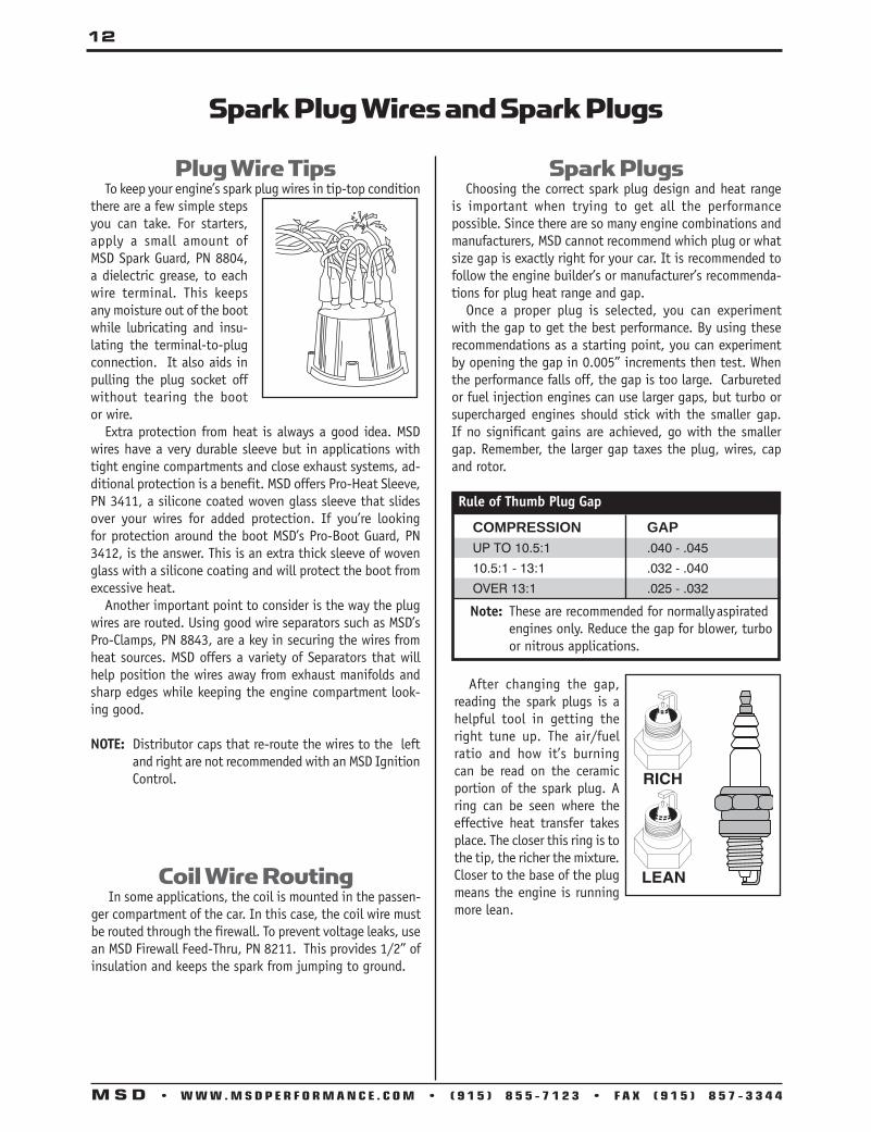
Plug Wire Tips To keep your engine’s spark plug wires in tip-top condition there are a few simple steps you can take. For starters, apply a small amount of MSD Spark Guard, PN 8804, a dielectric grease, to each wire terminal. This keeps any moisture out of the boot while lubricating and insu-lating the terminal-to-plug connection. It also aids in pulling the plug socket off without tearing the boot or wire. Extra protection from heat is always a good idea. MSD wires have a very durable sleeve but in applications with tight engine compartments and close exhaust systems, ad-ditional protection is a benefit. MSD offers Pro-Heat Sleeve, PN 3411, a silicone coated woven glass sleeve that slides over your wires for added protection. If you’re looking for protection around the boot MSD’s Pro-Boot Guard, PN 3412, is the answer. This is an extra thick sleeve of woven glass with a silicone coating and will protect the boot from excessive heat. Another important point to consider is the way the plug wires are routed. Using good wire separators such as MSD’s Pro-Clamps, PN 8843, are a key in securing the wires from heat sources. MSD offers a variety of Separators that will help position the wires away from exhaust manifolds and sharp edges while keeping the engine compartment look-ing good.
NOTE: Distributor caps that re-route the wires to the left and right are not recommended with an MSD Ignition Control.
Spark Plugs Choosing the correct spark plug design and heat range is important when trying to get all the performance possible. Since there are so many engine combinations and manufacturers, MSD cannot recommend which plug or what size gap is exactly right for your car. It is recommended to follow the engine builder’s or manufacturer’s recommenda-tions for plug heat range and gap. Once a proper plug is selected, you can experiment with the gap to get the best performance. By using these recommendations as a starting point, you can experiment by opening the gap in 0.005” increments then test. When the performance falls off, the gap is too large. Carbureted or fuel injection engines can use larger gaps, but turbo or supercharged engines should stick with the smaller gap. If no significant gains are achieved, go with the smaller gap. Remember, the larger gap taxes the plug, wires, cap and rotor.
Spark Plug Wires and Spark Plugs
Rule of Thumb Plug Gap
COMPRESSION GAP UP TO 10.5:1 .040 - .045
10.5:1 - 13:1 .032 - .040
OVER 13:1 .025 - .032
Coil Wire Routing In some applications, the coil is mounted in the passen-ger compartment of the car. In this case, the coil wire must be routed through the firewall. To prevent voltage leaks, use an MSD Firewall Feed-Thru, PN 8211. This provides 1/2” of insulation and keeps the spark from jumping to ground.
After changing the gap, reading the spark plugs is a helpful tool in getting the right tune up. The air/fuel ratio and how it’s burning can be read on the ceramic portion of the spark plug. A ring can be seen where the effective heat transfer takes place. The closer this ring is to the tip, the richer the mixture. Closer to the base of the plug means the engine is running more lean.
Note: These are recommended for normally aspirated engines only. Reduce the gap for blower, turbo or nitrous applications.
13
M S D • W W W . M S D P E R F O R M A N C E . C O M • ( 9 1 5 ) 8 5 5 - 7 1 2 3 • F A X ( 9 1 5 ) 8 5 7 - 3 3 4 4
Distributor Setup MSD offers a variety of distributors designed for different applications ranging from low profile and small diameter models to a front drive distributor. You can have the most powerful ignition available, but if you are not accurately triggering all of that energy or not getting it to the right spark plug at the precise moment, all of that power is be-ing wasted. Due to the increased energy output of an MSD Ignition Control, proper setup of the distributor is very important. A good quality cap and rotor should always be used and inspected on a regular basis. Note that areas with higher humidity are more succeptible to carbon tracking or spark scatter due to condensation build up. Another problem that can arise within a distributor cap is called ionization. Ionization occurs when the air inside the cap becomes electrically charged resulting in spark scatter or crossfire. It is more prevalent in smaller caps and again in areas with higher humidity. MSD rotors are designed with high vanes to help stir up the air preventing a charged area from building up. For more prevention, you can drill vent holes in the cap to release the pressure and to introduce fresh air. The holes should be at the height of the rotor skirt and at least 1/4” in diameter. Also, position the holes opposite the intake manifold and in dusty climates, it is a good idea to epoxy screens over the holes. If clearance is not an issue on your application, use as large a cap as possible such as the MSD Cap-A-Dapt, PN 8420 and PN 8445 or the Pro-Cap, PN 7445.
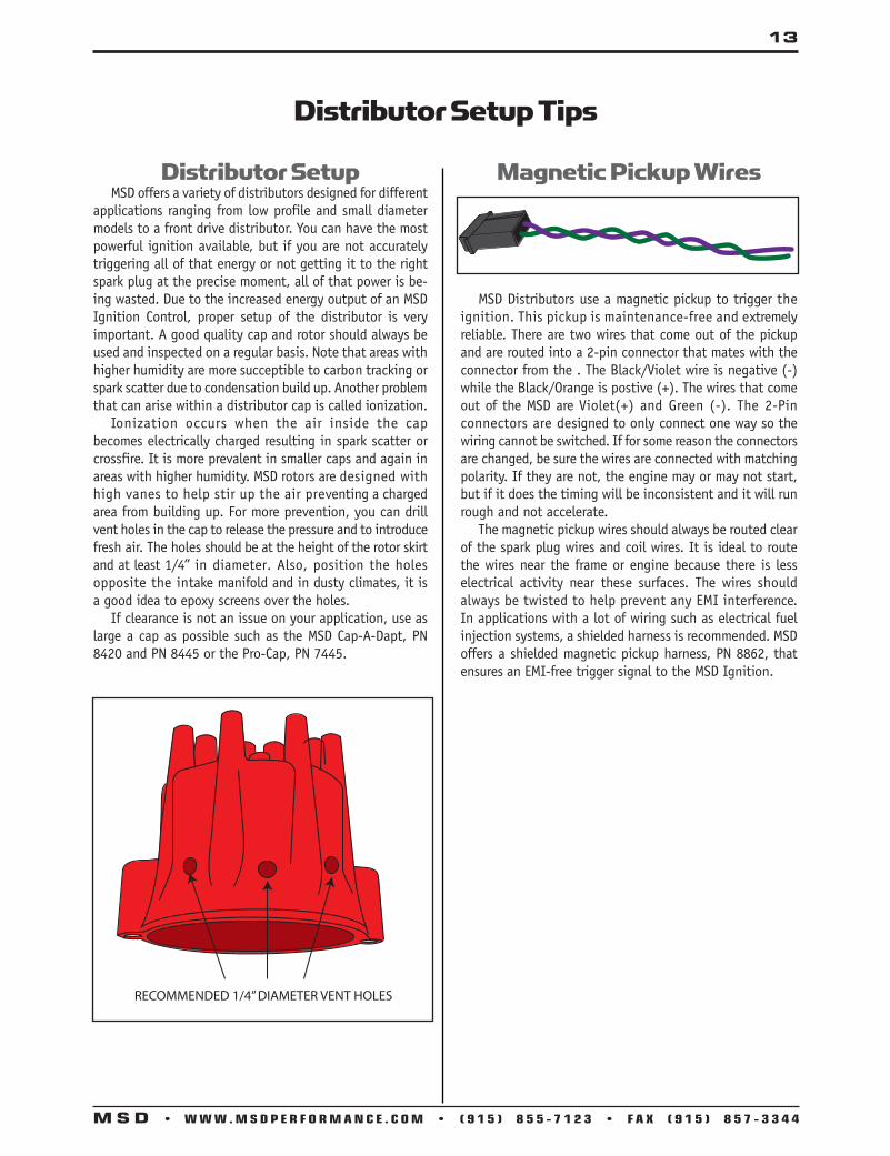
Magnetic Pickup Wires
MSD Distributors use a magnetic pickup to trigger the ignition. This pickup is maintenance-free and extremely reliable. There are two wires that come out of the pickup and are routed into a 2-pin connector that mates with the connector from the . The Black/Violet wire is negative (-) while the Black/Orange is postive (+). The wires that come out of the MSD are Violet(+) and Green (-). The 2-Pin connectors are designed to only connect one way so the wiring cannot be switched. If for some reason the connectors are changed, be sure the wires are connected with matching polarity. If they are not, the engine may or may not start, but if it does the timing will be inconsistent and it will run rough and not accelerate. The magnetic pickup wires should always be routed clear of the spark plug wires and coil wires. It is ideal to route the wires near the frame or engine because there is less electrical activity near these surfaces. The wires should always be twisted to help prevent any EMI interference. In applications with a lot of wiring such as electrical fuel injection systems, a shielded harness is recommended. MSD offers a shielded magnetic pickup harness, PN 8862, that ensures an EMI-free trigger signal to the MSD Ignition.
Distributor Setup Tips
RECOMMENDED 1/4” DIAMETER VENT HOLES

14
M S D • W W W . M S D P E R F O R M A N C E . C O M • ( 9 1 5 ) 8 5 5 - 7 1 2 3 • F A X ( 9 1 5 ) 8 5 7 - 3 3 4 4
Distributor Setup Tips
If the distributor has vacuum advance, leave it connected and check the phasing at your average driving rpm and at a lower rpm. At high rpm, note the rotor position and mark it on the cap terminal, then check it at low rpm and again mark the rotor position. The phasing should be set in the middle. If the phasing is not correct on a points or electronic triggered distributor, the trigger device must be moved until rotor/terminal alignment is achieved. (MSD magnetic pickup distributors are set at the factory and should not require adjusting.) If your application does require adjustment MSD offers a Cap-A-Dapt with an adjustable rotor, PN 8420. This compensates for the phasing without having to move the trigger mechanism. If you are using a Crank Trigger system to trigger the ignition, rotor phasing is easy to set by adjusting the hous-ing of the distributor.
Rotor Phasing Rotor phasing is the alignment between the rotor tip and the distributor cap terminal when the spark occurs. If the rotor tip is not aligned with the post when the spark occurs, the spark may find another path to ground resulting in scattered timing or a missfire. On engines with extreme cylinder pressures such as nitrous or superchargers the rotor phasing becomes even more important. To check rotor phasing, you need an extra cap that you can drill or cut a hole in to expose a terminal. It may help to mark a reference center line on the rotor tip and the terminal post with white correction fluid. Connect a timing light to the wire of the exposed terminal. With the engine running, the phasing can be observed. It is correct when the center line reference marks are aligned.
For applications that advance or retard the timing electronically, rotor phasing must be taken into consideration. If a multiple stage nitrous engine removes 16° of timing at top end, the rotor tip will be past the cap terminal when the spark is triggered.
Clockwise Rotation
Counter Clockwise Rotation
NOTE: MSD offers two adjustable rotors; PN 84211 (to replace PN 8467) and the PN 8421 (to replace the PN 8423). These will help you adjust the rotor phasing when not using a Crank Trigger.
SEE MSDVIDEOS.COM

15
M S D • W W W . M S D P E R F O R M A N C E . C O M • ( 9 1 5 ) 8 5 5 - 7 1 2 3 • F A X ( 9 1 5 ) 8 5 7 - 3 3 4 4
Most MSD Distributors with a magnetic pickup features an adjustable mechanical advance assembly. The distributors with this feature are supplied with three sets of advance springs and four stop bushings. The advance assembly is made up of weights, springs, an advance cam and an advance stop bushing. The distributor can be used in a wide selection of applications by chang-ing the springs and stop bushing only. There is no need to change the weights or advance cam.
Timing Functions There are several different timing specifications that are used when referring to the ignition timing. Initial Timing: This is the base or idle timing. It is
the amount of timing set in the engine before any advance begins.
Mechanical Advance (Centrifugal): This is a mechanical feature on most distributors that advances the timing as engine rpm increases. The amount of advance is de-termined by the stop bushing and the rate of ad vance is determined by the tension of the springs.
Vacuum Advance: Some of the MSD Distributors are equipped with a vacuum advance canister. Under partial throttle (high vacuum) conditions this vacuum advance increases the timing to increase the economy.
Total Timing: This is the total of the Initial Timing, Cen-trifugal advance and if equipped, the vacuum advance. For example: 8° Initial + 21° Centrifugal = 29° Total Timing.
Tips on Choosing an Advance Curve
The function of the advance curve is to match the igni-tion timing to the burning rate of the fuel and speed (rpm) of the engine. Any factor changing the burning rate of the fuel or the engine speed can cause a need for an ignition timing change. These factors range from fuel octane to the shape of the combustion chamber. Check with your engine builder to determine what ignition curve will best suit your engine and driving habits. Page 16 shows the different curves you can select with an MSD distributor.
Selecting the Advance Springs
The advance springs determine how quick the ad-vance comes in. The starting point of the advance curve is controlled by the length and tension of the spring. The slope, or how fast the curve comes in is determined by spring tension.
Mechanical Advance Setup Tips
To change the advance springs, simply use a set of needle nose pliers and pull the spring off.
SPRING COMBINATION RATE OF ADVANCE 2-Heavy Silver SLOWEST 1-Heavy Silver 1-Light Blue 1-Heavy Silver 1-Light Silver 2-Light Blue 1-Light Silver 1-Light Blue 2-Light Silver FASTEST
Selecting the Advance Stop Bushings
The advance stop bushing determines the amount of advance available to the centrifugal assembly. There are four different bushings with their amounts shown below.
Red - 28° Blue - 21° Silver - 25° Black - 18°
To change the advance stop bushing, remove the locknut and washer on the bottom of the advance assembly. Remove the bushing and install the new one.

16
M S D • W W W . M S D P E R F O R M A N C E . C O M • ( 9 1 5 ) 8 5 5 - 7 1 2 3 • F A X ( 9 1 5 ) 8 5 7 - 3 3 4 4
Locking Out the Centrifugal Advance
If you would like to lock out the centrifugal advance or are converting to a Flying Magnet Crank Trigger, the MSD centrifugal advance can easily be locked out. To begin, remove the advance springs and weights. Next, remove the roll pin from the end of the shaft so the shaft can be pulled out of the advance assembly about two inches. Rotate the shaft 180° and position the stop bushing pin in the small hole on the advance assembly. Install the locknut and washer to the stop bushing pin, then install the roll pin.
Locking Out the Centrifigul Advance .
Distributor Advance Graphs The following charts show the variety of ignition curves you can achieve with an MSD Distributor.
NOTE: This is a general overview of locking-out the mechanical advance. Refer to you distributor’s instructions for specific applications.

17
M S D • W W W . M S D P E R F O R M A N C E . C O M • ( 9 1 5 ) 8 5 5 - 7 1 2 3 • F A X ( 9 1 5 ) 8 5 7 - 3 3 4 4
Distributor Setup TipsHEI Vacuum Advance Stop Plate, PN 84281For MSD Pro-Billet HEI, PN 8365 and Street Fire HEI, PN 8362The HEI Vacuum Advance Stop, allows you to limit the amount of vacuum advance that occurs while driving. It is designed for use on the Street Fire HEI, PN 8362 and the MSD Pro-Billet, PN 8365. The two are easy to distinguish; the Street Fire has a cast aluminum housing while the MSD model is billet, polished aluminum. There are four positions that the Stop can be installed as shown.
0°
14°
17°
14°11°8°5° 17°
D ABC
D
CB
A
14°
11°8°
11°
5°8°
thru
thru thru
thru
0°
22°
25°
22°19°16°13°25°
DABC
MSD PRO-BILLET HEI PN 8365
STREET FIRE HEI PN 8362
D
CB
A
22°
19°19°
16°
13°16°
thru
thru thru
thru

18
M S D • W W W . M S D P E R F O R M A N C E . C O M • ( 9 1 5 ) 8 5 5 - 7 1 2 3 • F A X ( 9 1 5 ) 8 5 7 - 3 3 4 4
The MSD Flying Magnet Crank Trigger System is the most accurate way possible to trigger the ignition. This is due to the fact that the trigger signal is coming directly from the source of piston position in the cylinder; the crankshaft. Distributors are accurate, but the piston position is de-rived through the timing chain, the camshaft, cam gear and finally to the distributor shaft. There are no mechani-cal variables in piston position when using a crank trigger system.
Non-Magnetic Pickup The MSD Crank Trigger System uses a non-magnetic pickup to trigger the ignition. Magnets are embedded in the flywheel to produce the trigger signal. The non-magnetic pickup can only be triggered by the magnets in the flywheel. This design prevents the chance of false triggering. When installing the pickup, it is recommended to twist the wires together and route the wires near the frame or engine. These areas act as an electrical shield against elec-trical interfer-ence in the air. Also keep the wires away from any spark plug wires, coil wires and ignition wires. MSD offers a shielded harness, PN 8862, that is recommended for high powered engines or EFI systems.
Pickup Mounting The MSD Crank Trigger Kits come with all of the hardware needed to mount the pickup. Many kits feature a bracket that can be installed on either side of the engine block. Some kits are also supplied with several spacers to help obtain the correct alignment of the pickup and wheel. Due to the variety of balancers and pulleys, some modifying may be required to achieve the correct positioning of the bracket and pickup.
Trigger Wheel Mounting Unlike conventional crank trigger systems using a mag-netic pickup, the MSD trigger wheel must be mounted in the proper position. This is due to the polarity of the magnets in the wheel. If the wheel is reversed, the trigger signal will be affected and may advance the timing and cause inconsistent triggering accuracy. On the wheel there is an arrow which must point in the same direction as the engine rotation. Make sure this is installed correctly. When the wheel and trigger pickup bracket are mounted, make sure the pickup is positioned in the center of the trigger wheel. If it is not, the trigger signal can be af-fected. If they are not aligned, the bracket may require different spacers.
Flying Magnet Crank Trigger Tips
Setting the Air Gap The air gap between the pickup and trigger wheel is important, however it does not affect the performance in regards to your ET or mph. It affects the strength of the trigger signal. The farther away the pickup is from the wheel the weaker the trigger signal becomes. This could come into effect at cranking rpm. The minimum air gap is 0.050” and any closer the chance of the wheel hitting the pickup at high rpm comes into play. Some big cubic inch engine builders (600-800ci) recommend 0.060”-0.080” air gap due to the flexing of the crankshaft. A good rule of thumb is to run the pickup all the way in until it contacts the trigger wheel. Then, back the pickup out one full turn. This will set approximately 0.060” airgap, but always check the gap with a set of feeler gauges and in different areas of the wheel.
Tech Tip: Go to MSDvideos.com on the internet and look under “Installing MSD’s Flying Magnet Crank Trigger”.

19
M S D • W W W . M S D P E R F O R M A N C E . C O M • ( 9 1 5 ) 8 5 5 - 7 1 2 3 • F A X ( 9 1 5 ) 8 5 7 - 3 3 4 4
Common Firing Orders

20
M S D • W W W . M S D P E R F O R M A N C E . C O M • ( 9 1 5 ) 8 5 5 - 7 1 2 3 • F A X ( 9 1 5 ) 8 5 7 - 3 3 4 4
20
M S D • W W W . M S D P E R F O R M A N C E . C O M • ( 9 1 5 ) 8 5 5 - 7 1 2 3 • F A X ( 9 1 5 ) 8 5 7 - 3 3 4 4
Atomic EFIPN 2910 - Throttle Body Kit
FUELFILTER
FUEL TANK
FUELPUMP
IT IS RECOMMENDED TO MOUNT THE FUEL PUMP IN THE TANK WHENEVER POSSIBLE. IF IT MUST BE MOUNTED EXTERNALLY, MOUNT THE PUMP WITHIN 2-FEET OF THE FUEL TANK SENDING UNIT.
NOTE: IF RUNNING A RETURNLESS FUEL SYSTEM, THE PUMP MUST BE MOUNTED IN THE TANK.
RETURN LINE
MSD ADJUSTABLEREGULATOR
NOTE: DO NOT USE TUBING (HARD FUEL LINES) WITH THE ATOMIC EFI SYSTEM.
FUEL SYSTEM EXAMPLE
Wire FunctionsThere are several wires and connectors on the throttle body. Not all of these wires will be connected on every application. Following is a chart of each wire.
REQ. / OPT. Wire Color Description
REQ Yellow This connects to the Engine Coolant Temperature Sensor. Black REQ White This is the tach input wire for the EFI responsible for triggering the system. It connects
to the tach output of an MSD Ignition Control or Ready-to-Run Distributor. It can also be connected to the coil negative terminal when using a stock type ignition such as points or a GM HEI distributor. Note: This wire is not used when the magnetic pickup wire is being used for ignition timing.
OPTIONAL Yellow This is a tach output wire. Connect this wire to the White points input wire on an MSD ignition unit only when using the Atomic to control timing. If the Atomic is not controlling timing this wire can be used as a 12 volt square wave trigger to a tachometer.
OPTIONAL Orange This is an AC kick-up wire. When 12 volts are supplied to this wire it will provide a small rpm "kick-up" in the idle to compesate for an added load to the engine from the air conditioner compressor. It will also activate the primary cooling fan (when two are used).
OPTIONAL Violet (+) This is the input for a magnetic pickup, such as from an MSD distributor. This connector is only used when the Atomic is controlling ignition timing.
REQ CAN-Bus The 6-pin connector must connect to the Power Module. Do NOT cut this harness. MSD
Green (–)
used with timing control
used with A/C
used with timing control
Atomic Return Style Fuel System
21
M S D • W W W . A T O M I C E F I . C O M • ( 9 1 5 ) 8 5 5 - 7 1 2 3 • F A X ( 9 1 5 ) 8 5 7 - 3 3 4 4
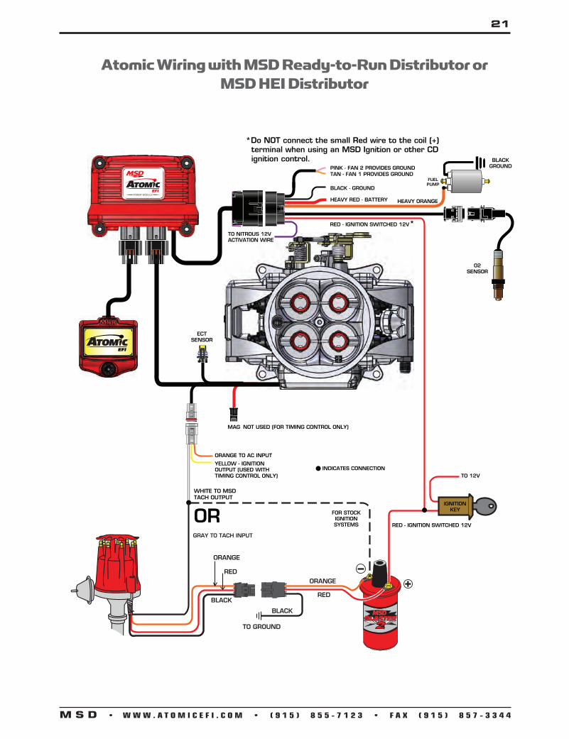
ECTSENSOR
PINK - FAN 2 PROVIDES GROUNDTAN - FAN 1 PROVIDES GROUND
RED - IGNITION SWITCHED 12V*
FUEL PUMP
BLACK - GROUND
HEAVY RED - BATTERY
O2SENSOR
BLACK GROUND
NOT USED (FOR TIMING CONTROL ONLY)MAG
ORANGE TO AC INPUT
YELLOW - IGNITION OUTPUT (USED WITH TIMING CONTROL ONLY)
WHITE TO MSD TACH OUTPUT
HEAVY ORANGE
*Do NOT connect the small Red wire to the coil (+) terminal when using an MSD Ignition or other CD ignition control.
RED - IGNITION SWITCHED 12V
GRAY TO TACH INPUT
INDICATES CONNECTIONTO 12V
IGNITIONKEYOR FOR STOCK
IGNITION SYSTEMS
TO NITROUS 12V ACTIVATION WIRE
Atomic Wiring with MSD Ready-to-Run Distributor or MSD HEI Distributor

22
M S D • W W W . M S D P E R F O R M A N C E . C O M • ( 9 1 5 ) 8 5 5 - 7 1 2 3 • F A X ( 9 1 5 ) 8 5 7 - 3 3 4 4
GREEN (-)VIOLET (+)
ECTSENSOR
REVLIMITER
DIGITAL 6AL
WHITE
ORANGE TO AC INPUT
WHITE
YELLOWNOT USED
ORANGE
BLACK
MAG PICKUP NOT USED
Orange (+) and Black (-) are the only wires that connect to the coil.
GRAY
*Do NOT connect the small Red wire to the coil (+) terminal when using an MSD Ignition or other CD ignition control. PINK - FAN 2 PROVIDES GROUND
TAN - FAN 1 PROVIDES GROUND
RED - IGNITION SWITCHED 12V*
FUEL PUMP
BLACK - GROUND
HEAVY RED - BATTERY
O2SENSOR
BLACK GROUND
HEAVY ORANGE
RED - IGNITION SWITCHED 12V
INDICATES CONNECTION
TO 12V
IGNITIONKEY
TO NITROUS 12V ACTIVATION WIRE
NOTUSED
Atomic Wiring with an MSD Ignition Control

23
M S D • W W W . A T O M I C E F I . C O M • ( 9 1 5 ) 8 5 5 - 7 1 2 3 • F A X ( 9 1 5 ) 8 5 7 - 3 3 4 4
Figure 19 Atomic Wiring to use Timing Control.
GREEN (-)VIOLET (+)
ECTSENSOR
REVLIMITER
DIGITAL 6ALONLY USED WITH TIMING CONTROL.
CONNECTS TO MSD DISTRIBUTOR
PICKUP
WHITE - NOT USEDORANGE TO AC INPUTDISTRIBUTOR
WHITEYELLOW
ORANGE
BLACK
MAG PICKUP NOT USED
Orange (+) and Black (-) are the only wires that connect to the coil.
GRAYTACH OUTPUT
*Do NOT connect the small Red wire to the coil (+) terminal when using an MSD Ignition or other CD ignition control. PINK - FAN 2 PROVIDES GROUND
TAN - FAN 1 PROVIDES GROUND
RED - IGNITION SWITCHED 12V*
FUEL PUMP
BLACK - GROUND
HEAVY RED - BATTERY
O2SENSOR
BLACK GROUND
HEAVY ORANGE
RED - IGNITION SWITCHED 12V
TO NITROUS 12V ACTIVATION WIRE
Atomic Wiring with an MSD Ignition Control

24
M S D • W W W . M S D P E R F O R M A N C E . C O M • ( 9 1 5 ) 8 5 5 - 7 1 2 3 • F A X ( 9 1 5 ) 8 5 7 - 3 3 4 4
MSD Atomic EFI Trouble Shooting
No
No
No
No
No
No
NoYes
Yes
Yes
Yes
Yes
Yes
Yes
YesNo
Have you completed the Pre-Start Checklist in the Atomic instructions?
Does the engine start?
Please check all of the items on that list before continuing.
Did the system show an RPM signal during cranking?
Please check for power to the fuel pump or other fuel issues.
Did that RPM signal correlate to the actual engine speed?
Please check to see the Atomic is getting a proper trigger signal from the distributor or ignition box.Is it possible
that the engine is flooded?
Please check to see the Atomic is getting a proper trigger signal from the distributor or ignition box.
Does the engine have spark?
Please follow the Flood Clear directions on page 13.
Check the ignition system to ensure proper functioning.
Engine starts! Go to the next page.
Does the engine start?
If each of the aforementioned items checks out and the non-start issue still exists, Please contact MSD Customer Support at 915-855-7123.
Did the system show proper Fuel Pressure?

25
M S D • W W W . A T O M I C E F I . C O M • ( 9 1 5 ) 8 5 5 - 7 1 2 3 • F A X ( 9 1 5 ) 8 5 7 - 3 3 4 4
The engine starts. Is it hard starting?
Is this the first time you have started the engine?
Has the engine been allowed to idle for at least 10 minutes?
Is the Atomic EFI controlling the engine’s ignition timing.
Let the engine run for at least 10 minutes. Then shut it off and start it again.
Letting the engine run at temperature for 10 minutes will allow the system to start learning.
Has the throttle been adjusted?
Refer to page 14 of the instructions to ensure the throttle is set for your engine.
Refer to page 13 to learn how to correct and clear codes.
Does the Handheld show any errors?
Does the system maintain fuel pressure during cranking/idling?
Is the engine hard starting?
Refer to pages 4 - 6 for instructions on the Fuel System. It must be able to maintain pressure at all times.
The engine is easy starting! Go to the next page.
If each of the aforementioned items checks out and the hard starting issue still exists, please contact MSD Customer Support at 915-855-7123.
No
Yes
Yes
Yes
Yes
Yes
Continue
Yes
Yes
Yes
Yes
No
No
No
Pleasereview the
instructions forsetting and controlling ignition timing with the
Atomic EFI.See pages
15-17.
No
No
No
No
Continued from previous page

26
M S D • W W W . M S D P E R F O R M A N C E . C O M • ( 9 1 5 ) 8 5 5 - 7 1 2 3 • F A X ( 9 1 5 ) 8 5 7 - 3 3 4 4
Yes
No
Yes
Yes
Yes
Yes
Yes
Yes
No
No
No
No
No
No
The engine is easy starting. Does it idle well?
Has the engine had the chance to idle for 10 minutes at operating temperature 160° or above?
Allow the engine to idle at running temp. This will allow self-tuning to adjust items as needed.
Are there any vacuum leaks?
Ensure that there are NO vacuum leaks that could affect the amount of air in the engine.
Are you sure the ignition timing and rotor phasing are correct?
Are the throttle blades adjusted for the engine? See page 14
The IAC can only do so much to ensure the right amount of air gets in the engine. Refer to page 14 for throttle adjustment.
Does the idle Air/Fuel Ratio make sense?
Excessive Lean or Rich targets can make it hard for an engine to idle steady. Use the Handheld to double check the target to ensure it is appropriate.
Does the engine idle well?
If each of the aforemen-tioned items checks out and the rough idle issues still exists, please contact MSD Customer Support at 915-855-7123.
The engine idles well! Go to the next page.
If timing is off an engine can struggle to idle regardless of the fuel system. Make sure the distributor is in proper alignment.
Continued from previous page

27
M S D • W W W . A T O M I C E F I . C O M • ( 9 1 5 ) 8 5 5 - 7 1 2 3 • F A X ( 9 1 5 ) 8 5 7 - 3 3 4 4
Yes
No
Yes
Yes
Yes
Yes
Yes
Yes
Yes
No
No
No
No
No
No
No
If each of the aforemen-tioned items checks out and the poor drivability issue still exists, please contact MSD Customer Support at 915-855-7123.
Your engine starts, idles, and drives well. Enjoy the Atomic EFI!
Do you have drivability issues?
If timing is off an engine can struggle to idle regardless of the fuel system. Make sure the distributor is in proper alignment.
Has the Atomic EFI had time to learn all the parts of your fuel maps?
Check to see that the fuel system is maintaining pressure. If the Atomic looses fuel pressure for any reason it will cause the engine to run poorly.
Are you sure the ignition timing and rotor phasing are correct?
Does the Atomic EFI maintain adequate fuel pressure?
The Atomic is designed to always hit the designated Air Fuel Ratio Targets. If these targets are much too low or high for an engine it will run poorly. Check to ensure the targets make sense for your engine.
Do the Air Fuel Ratio Targets make sense?
When there is an increase in throttle position the engine can require extra fuel that isn’t accounted for in the regular fuel maps. See page 12 to learn how we solve this issue with the “Pump Squirt” feature of the Atomic.
Even a small exhaust leak can alter the WBO2 readings. If this happens it will have a dramatic effect on the engine’s performance. Always ensure thre are NO leaks in the exhaust?
Does the engine struggle to keep up during throttle increases?
Are there any exhaust leaks?
The engine is smooth idling. Do you have any drivability issues?
The Atomic needs run time in each area of the fuel maps to learn the best settings for your engine. It could take up to a week of normal daily driving to adjust all the maps.

28
M S D • W W W . M S D P E R F O R M A N C E . C O M • ( 9 1 5 ) 8 5 5 - 7 1 2 3 • F A X ( 9 1 5 ) 8 5 7 - 3 3 4 4
Atomic LS EFIPN 2950 - Master Kit LS2/LS3
Atomic LS7 EFI Master KitPN 2960
MAP
ECT
INJ8
INJ6
COILS1357
CANCAN
ETC2/V V T** ALT
COILS2468
DRIVERSIDE
PASSENGERSIDE
INJ4
INJ2
INJ7
INJ5
IAC
ETC1/TPS
INJ1
INJ3
OIL
PWR
CRANK
PWR
IAT
AC
IAC2*
FPSF
GH
FG
H
DL
PH
ID
LP
HI
GND
GND
CAM
PWR
TOPOWERMODULE
**FOR DUAL THROTTLE BODIES
**FOR ENGINES WITH V V T OPTIONS
(NOT USED)
Atomic LS EFI Rails and Connections

29
M S D • W W W . A T O M I C E F I . C O M • ( 9 1 5 ) 8 5 5 - 7 1 2 3 • F A X ( 9 1 5 ) 8 5 7 - 3 3 4 4
COIL CONNECTOR, CYLINDERS 2, 4, 6, 8BLACK Pin-A GroundTAN Pin-B Coil-2LIGHT GREEN Pin-C Coil-4BROWN Pin-E Sensor GroundWHITE Pin-F Coil-6LIGHT BLUE Pin-G Coil-8PINK Pin-H 12 Volts Supply Pin-D NOT USED COIL CONNECTORS, CYLINDERS 1, 3, 5, 7BLACK Pin-A GroundBLUE Pin-B Coil-7BROWN WHITE Pin-C Coil-5BROWN Pin-E Sensor GroundGREEN Pin-F Coil-3TAN Pin-G Coil-1PINK Pin-H 12 Volts Supply Pin-D NOT USED THROTTLE POSITION SENSOR (TPS)ORANGE PIN-1 5V ReferenceBLACK PIN-2 GroundBLUE PIN-3 Signal out IDLE AIR CONTROL (IAC)ORANGE Pin-A Coil 1BGRAY Pin-B Coil 1ABLUE Pin-C Coil 2ABLACK Pin-D Coil 2B INTAKE AIR TEMPERATURE (IAT)BLACK Pin-A GroundVIOLET Pin-B Signal
Pinouts for the Coil Connector and IACThe following charts show the color, function and location on each connector in case you need to remove or extend the wiring for relocated coils or a reversed intake manifold mount. More information is available at www.atomicefi.com
NOTE: PAGE 18 SHOWS PINOUTS FOR THE COIL CONNECTORS AND IAC.

30
M S D • W W W . M S D P E R F O R M A N C E . C O M • ( 9 1 5 ) 8 5 5 - 7 1 2 3 • F A X ( 9 1 5 ) 8 5 7 - 3 3 4 4
CODE NAME
TPS
MAP
IAT
ECT
BATT
INJ DC
FUEL PRESSURE
WBO2
FP CAV
MAP SELECT
BARO
The following chart gives the most likely solution(s) to each possible error.
Clearing History ErrorsThere are two ways to clear an error. First, the code will erase after 10 key cycles. Second, is to simply navigate to the message screen and push the joystick down to clear the codes.
WHAT IT MEANS
There is no reading for the Throttle Po-sition Sensor.
There is no reading for the Manifold Absolute Pressure Sensor.
There is no reading for the Inlet Air Temperature Sensor. The ECU will de-fault to 275°F when shorted or -40°F when open.
There is no reading for the Engine Coolant Temperature Sensor. he ECU will default to 275°F when shorted or -40°F when open.
The Atomic is receiving the wrong volt-age. The unit is measuring either less than 9 volts or greater than 16 volts.
Excessive Injector Duty Cycle
There is no reading for the Fuel Pres-sure Sensor.
A. "NOT CONNECTED" indicates that no sensor is detected.B. "ERROR" indicates that the sensor has failed.
This code will set if there is an issue with Fuel Pump Cavitation (similar to vapor lock). It can only set when running a returnless fuel system. This may occur when the commanded fuel pressure (from the ECU) is different than the fuel pressure (at the sending unit).
ECU compares the MAP reading with the Baro reading on key up. If these are different by more than 5kPa, the code is activated.
The baro sensor on the board is out of range. It will use the last know good value.
PROBABLE CORRECTION(S)
The sensor may be at fault.
The sensor maybe at fault.
Check to see that the sensor is properly installed and plugged in. If the sensor is connected but there is no signal, it will need to be replaced.
Check to see that the sensor is properly installed and plugged in. If the sensor is connected but there is no signal, it will need to be replaced.
Check that the Atomic has power and ground directly from the battery. Also be sure the vehicle's battery and charging system are in proper working order.
If you are running a returnless fuel system your engine's needs may exceed the Atomic's maximum capabilities. If you are running a return system check to see that you are main-taining the recommended fuel pressure. If you have adequate fuel pressure the engine's needs may exceed the Atomic's system capabilities.
The sensor will need to be replaced.
A. Check to see that the sensor is securely plugged into the system.B. The sensor will need to be replaced.Note that 'warming up' is normal during start-up for the first 20 seconds.
This means you need to review your fuel pump system and confirm that your application meets the requirements to run a returnless (PWM) system. Also check the filters, the sock in the tank and inspect the lines for any kinks or pinches that would affect the fuel flow and pressure of the system. If everything checks okay and the code continues, you may need to move to an in-tank pump, or use a regulated (return) fuel system.
Double check your MAP selection and make sure that you selected the correct P/N of sensor. It could also mean a problem with the Baro or MAP sensor itself (see above codes).
Turn the key off, wait 10 seconds and turn back on to see if the code remains. If so, call customer service. As long as the vehicle has not changed altitude by a large amount since the last key off (towed somewhere), everything will function normally.

31
MA
P
ECT
INJ8
*
INJ6
*
CO
ILS
1, 3
, 5
, 7
CA
NCA
N
ETC
/V
V T
ALT
CO
ILS
2, 4
, 6
, 8
DR
IVER
SID
EPA
SSEN
GER
SID
E
INJ4
*
INJ2
*
INJ7
*
INJ5
* IAC
ETC
/TP
S
INJ1
*
INJ3
*
OIL
CR
AN
K
Red
- P
OW
ER
Red
- P
OW
ER
IAT
Ora
nge
- A
C
IAC2
FPS
F G H
FGH
DLPHI DLPHIBla
ck - G
RO
UN
D
Bla
ckG
RO
UN
D
CA
M
Red
- P
OW
ER
TOPO
WER
MO
DU
LE
*IN
JECTO
RS A
DA
PTE
RS
AR
E IN
TER
CH
AN
GEA
BLE
. (E
V6
Ada
pter
s sh
own)
NO
TE: D
o no
t cr
oss
the
inje
ctor
har
ness
es w
hen
inst
allin
g th
em o
n th
e in
ject
ors.
A. Pin
k - 1
2V
B. O
rang
e - 5
VC. B
row
n - G
roun
dD
. O
rg/Yel
- S
igna
l
1. Sig
nal
2. 1
2V
1. Sig
nal
2. 1
2V
A. B
lack
- G
roun
dB
. Ta
n - Coi
l 2C. Lt
. G
reen
- C
oil 4
D. N
ot U
sed
E. B
row
n - R
ef G
ndF.
Whi
te - C
oil 6
G. Lt
. B
lue
- Coi
l 8H
. Pin
k - 1
2V
A. O
rang
e - 5
VB
. Lt
Gre
en - S
igna
lC. B
row
n - G
roun
d
1. Sig
nal
2. 1
2V
1. Sig
nal
2. 1
2V
A. B
lack
- G
roun
dB
. Vio
let
- Sig
nal
A. B
lack
- G
roun
d B
. Yel
low
- S
igna
l
A. O
rang
e - Coi
l 1B
B. G
ray
- Coi
l 1A
C. B
lue
- Coi
l 2A
D. B
lack
- C
oil 2
B
A. O
rang
e - Coi
l 1B
B. G
ray
- Coi
l 1A
C. B
lue
- Coi
l 2A
D. B
lack
- C
oil 2
B
A. N
ot U
sed
B. B
row
n - L
Term
C. N
ot U
sed
D. N
ot U
sed
A. B
row
nB
. Pin
kC. B
rn/W
hite
- G
ndD
. N
ot U
sed
E. G
reen
- T
PS1
F. O
rang
e - 5
VG
. Vio
let
- TP
S2
H. N
ot U
sed
A. B
row
nB
. Pin
kC. B
rn/W
hite
- G
ndD
. N
ot U
sed
E. G
reen
- T
PS1
F. O
rang
e - 5
VG
. Vio
let
- TP
S2
H. N
ot U
sed
1. G
reen
- C
AN
LO
2. Yel
low
- C
AN
HI
3. B
lk/R
ed - G
nd4
. B
lack
- G
nd5
. O
rang
e - Cra
nk6
. B
row
n - Cam
7. B
lue
- Ts
ync
8. G
ray
- Shi
eld
1. B
lack
- G
roun
d2
. O
rang
e - 5
V3
. W
hite
- S
igna
l
1. Sig
nal
2. 1
2V
1. B
lack
- G
roun
d2
. O
rang
e - 5
V3
. Lt
Blu
e - Sig
nal
A. B
lack
- G
roun
dB
. B
lue
- Coi
l 7C. B
rn/W
hite
- C
oil 5
D. N
ot U
sed
E. B
row
n - R
ef G
roun
dF.
Gre
en - C
oil 3
G. Ta
n - Coi
l 1H
. Pin
k - 1
2V
A. Pin
k - 1
2V
B. O
rang
e - 5
VC. B
row
n - G
roun
dD
. B
rn/W
ht - S
igna
l
1. Sig
nal
2. 1
2V
1. Sig
nal
2. 1
2V
1. O
rang
e - 5
V2
. B
lack
- G
roun
d3
. B
lue
- Sig
nal
TPS A
DA
PTE
R
1. Sig
nal
2. 1
2V
(NO
T CU
RR
EN
TLY
USED
)
(NO
T U
SED
O
N L
S7
)
Atomic LS EFIPN 2960 - Master Kit LS7
Atomic LS EFI Rails and Connections

32
M S D • W W W . M S D P E R F O R M A N C E . C O M • ( 9 1 5 ) 8 5 5 - 7 1 2 3 • F A X ( 9 1 5 ) 8 5 7 - 3 3 4 4
CODE NAME
TPS
MAP
IAT
ECT
BATT
INJ DC
FUEL PRESSURE
WBO2
FP CAV
MAP SELECT
BARO
WHAT IT MEANS
There is no reading for the Throttle Posi-tion Sensor.
There is no reading for the Manifold Ab-solute Pressure Sensor.
There is no reading for the Inlet Air Tem-perature Sensor. The ECU will default to 275°F when shorted or -40°F when open.
There is no reading for the Engine Cool-ant Temperature Sensor. he ECU will default to 275°F when shorted or -40°F when open.
The Atomic is receiving the wrong volt-age. The unit is measuring either less than 9 volts or greater than 16 volts.
Excessive Injector Duty Cycle
There is no reading for the Fuel Pressure Sensor.
A. "NOT CONNECTED" indicates that no sensor is detected.B. "ERROR" indicates that the sensor has failed.
This code will set if there is an issue with Fuel Pump Cavitation (similar to vapor lock). It can only set when running a returnless fuel system. This may occur when the commanded fuel pressure (from the ECU) is different than the fuel pressure (at the Fuel Pressure Sensor).
ECU compares the MAP reading with the Baro reading on key up. If these are different by more than 5kPa, the code is activated.
The Baro sensor voltage is out of range, and the ECU has defaulted to the last known good Baro value.
PROBABLE CORRECTION(S)
The sensor may be at fault. Check wiring and/or replace sensor.
The sensor maybe at fault. Check wiring and/or replace sensor.
Faulty sensor; loose or no connection. Check wiring and/or re-place sensor.
Faulty sensor; loose or no connection. Check wiring and/or re-place sensor.
Check the battery connection from the Power Module to the battery. Ensure that the battery and alternator are working cor-rectly.
If you are running a returnless fuel system your engine's needs may exceed the Atomic's maximum capabilities. If you are run-ning a return system check to see that you are maintaining the recommended fuel pressure. If you have adequate fuel pres-sure the engine's needs may exceed injector flow rate.
Faulty sensor; loose or no connection. Check wiring and/or re-place sensor.
A. Check to see that the sensor is securely plugged into the system. Inspect wiring if it is plugged into the system.B. The sensor will need to be replaced.Note that 'warming up' is normal during start-up for the first 20 seconds.
Check the fuel system and determine that it meets the requirements to run a returnless (PWM) system. Check the filters, the sock in the tank, and inspect the lines for any kinks or pinches that would affect the fuel flow and pressure of the system. If the code continues, the fuel system may need to be converted to an in-tank fuel pump and/or regulated (return) fuel system.
Double check your MAP selection and make sure that you selected the correct P/N of sensor. It could also mean a problem with the Baro or MAP sensor itself (see above codes).
Turn the ignition off. Wait 10 seconds, and turn the ignition back on. If the code remains, call customer service. Unless the vehicle has been through a large change in altitude since the last ignition on/off cycle (towed somewhere), everything will function normally.
The following chart gives the most likely solution(s) to each possible error.
Clearing History ErrorsThere are two ways to clear an error. First, the code will erase after 10 key cycles. Second, is to simply navigate to the message screen and push the joystick down to clear the codes.

33
ALT
A. N
ot U
sed
B. B
row
n - L
Term
C. N
ot U
sed
D. N
ot U
sed
1. O
rang
e - 5
V2
. B
lack
- G
roun
d3
. B
lue
- Sig
nal
TPS A
DA
PTE
RTP
S S
igna
l - B
lue
ALT
1. B
row
n-L
Term
2. N
ot U
sed
MA
P
ECT
INJ8
*
INJ6
*
CO
ILS
1,
3,
5,
7
CA
NCA
N
ETC
/V
V T
CO
ILS
2,
4,
6,
8
DR
IVER
SID
EPA
SSEN
GER
SID
E
INJ4
*
INJ2
*
INJ7
*
INJ5
* IAC
ETC
/TP
S
INJ1
*
INJ3
*
OIL
CR
AN
K
Red
- P
OW
ER
Red
- P
OW
ER
IAT
Ora
nge
- A
C
IAC2
FPS
F G H
EFG
DLPHI DLPHIBla
ck - G
RO
UN
D
Bla
ckG
RO
UN
D
CA
M
Red
- P
OW
ER
TOPO
WER
MO
DU
LE
*IN
JECTO
RS A
DA
PTE
RS
AR
E IN
TER
CH
AN
GEA
BLE
. (E
V6
Ada
pter
s sh
own)
NO
TE:
Do
not
cros
s th
e in
ject
or h
arne
sses
whe
n in
stal
ling
them
on
the
inje
ctor
s.
A. Pin
k - 1
2V
B. O
rang
e - 5
VC. B
row
n - G
roun
dD
. O
rg/Yel
- S
igna
l
1. Sig
nal
2. 1
2V
1. Sig
nal
2. 1
2V
A. B
lack
- G
roun
dB
. Ta
n - Coi
l 2C. Lt
. G
reen
- C
oil 4
D. N
ot U
sed
E. B
row
n - R
ef G
ndF.
Whi
te - C
oil 6
G. Lt
. B
lue
- Coi
l 8H
. Pin
k - 1
2V
A. O
rang
e - 5
VB
. Lt
Gre
en - S
igna
lC. B
row
n - G
roun
d
1. Sig
nal
2. 1
2V
1. Sig
nal
2. 1
2V
A. B
lack
- G
roun
dB
. Vio
let
- Sig
nal
A. B
lack
- G
roun
d B
. Yel
low
- S
igna
l
A. O
rang
e - Coi
l 1B
B. G
ray
- Coi
l 1A
C. B
lue
- Coi
l 2A
D. B
lack
- C
oil 2
B
A. O
rang
e - Coi
l 1B
B. G
ray
- Coi
l 1A
C. B
lue
- Coi
l 2A
D. B
lack
- C
oil 2
B
A. B
row
nB
. Pin
kC. B
rn/W
hite
- G
ndD
. N
ot U
sed
E. G
reen
- T
PS1
F. O
rang
e - 5
VG
. Vio
let
- TP
S2
H. N
ot U
sed
A. B
row
nB
. Pin
kC. B
rn/W
hite
- G
ndD
. N
ot U
sed
E. G
reen
- T
PS1
F. O
rang
e - 5
VG
. Vio
let
- TP
S2
H. N
ot U
sed
1. G
reen
- C
AN
LO
2. Yel
low
- C
AN
HI
3. B
lk/R
ed - G
nd4
. B
lack
- G
nd5
. O
rang
e - Cra
nk6
. B
row
n - Cam
7. B
lue
- Ts
ync
8. G
ray
- Shi
eld
1. B
lack
- G
roun
d2
. O
rang
e - 5
V3
. W
hite
- S
igna
l
1. Sig
nal
2. 1
2V
1. B
lack
- G
roun
d2
. O
rang
e - 5
V3
. Lt
Blu
e - Sig
nal
A. B
lack
- G
roun
dB
. B
lue
- Coi
l 7C. B
rn/W
hite
- C
oil 5
D. N
ot U
sed
E. B
row
n - R
ef G
roun
dF.
Gre
en - C
oil 3
G. Ta
n - Coi
l 1H
. Pin
k - 1
2V
A. Pin
k - 1
2V
B. O
rang
e - 5
VC. B
row
n - G
roun
dD
. B
rn/W
ht - S
igna
l
1. Sig
nal
2. 1
2V
1. Sig
nal
2. 1
2V
1. Sig
nal
2. 1
2V
(NO
T CU
RR
EN
TLY
USED
)
ALT
ER
NA
TOR
NO
TE:
Bot
h ty
pes
of a
lter
na-
tor
conn
ecto
rs h
ave
been
pro
vide
d to
ac
com
mod
ate
the
differ
ent
conf
igur
atio
ns.
Cut
the
one
not
use
d an
d ca
p th
e w
ire
with
the
heat
shri
nk p
rovi
ded
in t
he p
arts
bag
.
Atomic LS EFIPN 2957 - Master Kit 3-Bolt ManifoldPN 2958 - Master Kit 4-Bolt Manifold

34
M S D • W W W . M S D P E R F O R M A N C E . C O M • ( 9 1 5 ) 8 5 5 - 7 1 2 3 • F A X ( 9 1 5 ) 8 5 7 - 3 3 4 4
The following chart gives the most likely solution(s) to each possible error.
Clearing History Errors
CODE NAME
TPS
MAP
IAT
ECT
BATT
INJ DC
FUEL PRESSURE
WBO2
FP CAV
MAP SELECT
BARO
WHAT IT MEANS
There is no reading for the Throttle Posi-tion Sensor.
There is no reading for the Manifold Ab-solute Pressure Sensor.
There is no reading for the Inlet Air Tem-perature Sensor. The ECU will default to 275°F when shorted or -40°F when open.
There is no reading for the Engine Cool-ant Temperature Sensor. he ECU will default to 275°F when shorted or -40°F when open.
The Atomic is receiving the wrong volt-age. The unit is measuring either less than 9 volts or greater than 16 volts.
Excessive Injector Duty Cycle
There is no reading for the Fuel Pressure Sensor.
A. "NOT CONNECTED" indicates that no sensor is detected.B. "ERROR" indicates that the sensor has failed.
This code will set if there is an issue with Fuel Pump Cavitation (similar to vapor lock). It can only set when running a returnless fuel system. This may occur when the commanded fuel pressure (from the ECU) is different than the fuel pressure (at the sending unit).
ECU compares the MAP reading with the Baro reading on key up. If these are different by more than 5kPa, the code is activated.
The Baro sensor voltage is out of range, and the ECU has defaulted to the last known good Baro value.
PROBABLE CORRECTION(S)
The sensor may be at fault. Check wiring and/or replace sensor.
The sensor maybe at fault. Check wiring and/or replace sensor.
Faulty sensor; loose or no connection. Check wiring and/or re-place sensor.
Faulty sensor; loose or no connection. Check wiring and/or re-place sensor.
Check the battery connection from the Power Module to the battery. Ensure that the battery and alternator are working cor-rectly.
If you are running a returnless fuel system your engine's needs may exceed the Atomic's maximum capabilities. If you are run-ning a return system check to see that you are maintaining the recommended fuel pressure. If you have adequate fuel pres-sure the engine's needs may exceed the Atomic's system ca-pabilities.
Faulty sensor; loose or no connection. Check wiring and/or re-place sensor.
A. Check to see that the sensor is securely plugged into the system. Inspect wiring if it is plugged into the system.B. The sensor will need to be replaced.Note that 'warming up' is normal during start-up for the first 20 seconds.
Check the fuel system and etermine that it meets the requirements to run a returnless (PWM) system. Check the filters, the sock in the tank, and inspect the lines for any kinks or pinches that would affect the fuel flow and pressure of the system. If the code continues, the fuel system may need to be converted to an in-tank fuel pump and/or regulated (return) fuel system.
Double check your MAP selection and make sure that you selected the correct P/N of sensor. It could also mean a problem with the Baro or MAP sensor itself (see above codes).
Turn the ignition off. Wait 10 seconds, and turn the ignition back on. If the code remains, call customer service. Unless the vehicle has been through a large change in altitude since the last ignition on/off cycle (towed somewhere), everything will function normally.

35
M S D • W W W . M S D P E R F O R M A N C E . C O M • ( 9 1 5 ) 8 5 5 - 7 1 2 3 • F A X ( 9 1 5 ) 8 5 7 - 3 3 4 4
Original Ballast Resistor Wiring with a Blaster Ignition or MSD 5 Ignition
The MSD 5 and Blaster Ignitions are inductive ignitions which enhance the spark of the vehicle’s stock ignition. The MSD 5 is a multiple spark ignition, while the Blaster is a single spark, long duration design. Both are designed for entry level and budget build-ups and can be triggered with points or electronic ignitions. The Blaster can also be triggered by a magnetic pickup distributor such as the MSD Pro-Billet Distributors.
Ballast Resistors: If the vehicle has a ballast resistor or resistor wiring leading to the coil, leave it inline and connect the Red wire of the ignition before the resistor. If there are no resistors originally, the Blaster Ignition and MSD 5 do not require it. For aftermarket coils, use the coil manufacturer’s recomendations.
NOTE: Not recommended for use with a GM HEI Internal Coil Distributor.
Wire F unctions Red: Connects to the positive (+) terminal of the coil, or a switched 12v. Black: Connects to ground. Orange: Connects to the negative (-) terminal of the coil. White: Connects to the points or electronic ignition amplifier output.
Blaster Ignition Only Green: Magnetic pickup negative (-). Violet: Magnetic pickup positive (+).
Installing an MSD 5, PN 5200,or Blaster Ignition, PN 5900

36
M S D • W W W . M S D P E R F O R M A N C E . C O M • ( 9 1 5 ) 8 5 5 - 7 1 2 3 • F A X ( 9 1 5 ) 8 5 7 - 3 3 4 4
Blaster Ignition to Stock Magnetic Pickup Distributor
Blaster Ignition to Magnetic Pickup
Note: The MSD 5 Ignition does not have a magnetic pickup connector.

37
M S D • W W W . M S D P E R F O R M A N C E . C O M • ( 9 1 5 ) 8 5 5 - 7 1 2 3 • F A X ( 9 1 5 ) 8 5 7 - 3 3 4 4
Blaster/MSD 5 to Ford TFI Ignition
AUTOTRONIC CONTROLS CORPORATION
SERIAL NO..IGNITION
PART NO.
AUTOTRONIC CONTROLS CORPORATION
SERIAL NO..IGNITION
PART NO.
Blaster/MSD 5 to GM Dual Connector, External Coil
AUTOTRONIC CONTROLS CORPORATION
SERIAL NO..IGNITION
PART NO.
AUTOTRONIC CONTROLS CORPORATION
SERIAL NO..IGNITION
PART NO.

38
M S D • W W W . M S D P E R F O R M A N C E . C O M • ( 9 1 5 ) 8 5 5 - 7 1 2 3 • F A X ( 9 1 5 ) 8 5 7 - 3 3 4 4
Installing a Street Fire CDI Ignition, PN 5520
The Street Fire CDI is a base model CD, multiple spark ignition offered by MSD Ignition. The wiring colors and functions are shared with the 6-Series Ignitions. If you don’t see your application, go to the 6-Series Ignition section of this book.
Operating Specifications Spark Energy: 95 mJ Per Spark Primary Voltage: 435 Volts Secondary Voltage: 45,000 Volts Spark Series Duration: 20° Crankshaft Rotation RPM Range: 15,000 RPM with 14.4 Volts Voltage Required: 10-18 Volts, Negative Ground Current Draw .7 Amp per 1,000 RPM Weight and Size: 1.5 lbs., 6”L x 3.5”W x 1.75”H
Wire F unctions Power Leads: These are the two heavy gauge wires (14 gauge) and are responsible for getting
direct battery voltage to the Ignition. Heavy Red: This wire connects directly to the battery positive (+) terminal or to a positive
battery junction or the positive side of the starter solenoid. Note: Never connect to the alternator. Heavy Black: This wire connects to a good ground, either at the battery negative (-) terminal
or to the engine.
Red: Connects to a switched 12 volt source, such as the ignition key or switch. Orange: Connects to the positive (+) terminal of the coil. This is the only wire that makes
electrical contact with the coil positive terminal. Black: Connects to the negative (-) terminal of the coil. This is the only wire that makes
electrical contact with the coil negative terminal. Gray: Tach output wire. Connect to the tachometer or other rpm device. Trigger Wires: There are two circuits that can be used to trigger the Street Fire Ignition; a Points
circuit (White wire) and a Magnetic Pickup circuit (Violet and Green wires). The two circuits will never be used together.
White: This wire is used to connect to the points or electronic ignition amplifier output. Violet and Green: These wires are routed together in one harness to form the Magnetic Pickup connector.
The connector plugs directly into an MSD Distributor. It will also connect to factory magnetic pickups or other aftermarket pickups. The Violet wire is positive (+) and the Green is negative (-). When these wires are used, the White wire is not.
(Magnetic Pickup Connector)
WARNING: When using a capacitive discharge ignition control, there is high voltage present at the coil primary terminals. Never touch the coil or connect test equipment to these terminals.
WARNING: During installation, disconnect the battery. When disconnecting the battery always remove the negative cable first and install it last.

39
M S D • W W W . M S D P E R F O R M A N C E . C O M • ( 9 1 5 ) 8 5 5 - 7 1 2 3 • F A X ( 9 1 5 ) 8 5 7 - 3 3 4 4
GRAYTOTACH
WHITE
ORANGE
BLACK
SMALL RED
PN 5520
WWW.STREET-FIRE.COM
CDI MULTI-SPARK
IGNITION
®
NOTE: On dual point setups, it is necessary to remove the trailing set of points.
NOTE: Ballast Resistor is not necessary.
NOTE: Remove the coil terminal wires. The negative wire connects to the Street Fire White. The positive wire connects to the Street Fire Red. The Street Fire Orange connects to the coil positive terminal, Black connects to the coil negative terminal.
NOTE: Wiring of Street Fire Ignitions is the same as MSD 6-Series with the exception of the Gray Tach wire.
Street Fire CDI, PN 5520, to an MSD Distributor
BLACK/ORANGE
GRAYTOTACH
WHITE
(NOT U
SED)
ORANGE
BLACK
SMALL RED
DISTRIBUTORWITH
MAGNETIC PICKUP
BLACK/VIOLETPN 5520
WWW.STREET-FIRE.COM
CDI MULTI-SPARK
IGNITION
®
Street Fire CDI, PN 5520, to Points/Amplifier Style Ignition

40
M S D • W W W . M S D P E R F O R M A N C E . C O M • ( 9 1 5 ) 8 5 5 - 7 1 2 3 • F A X ( 9 1 5 ) 8 5 7 - 3 3 4 4
Wiring the Ready-to-Run Chevrolet DistributorRED
ORANGE
BLACK
TO COIL POSITIVE + 12 VOLTS
TO COIL NEGATIVE -
TO ENGINE GROUND
Ready-to-Run Distributors The Ready-to-Run line of Distributors from MSD are designed as a stand-alone distributor. They feature an ignition module built into the base of the unit that produces a high output, single spark. These distributors are easy to recognize as they have a 3-pin weathertight connector with a Red, Orange and Black wire. MSD Pro-Billet distributors with two wires require an MSD Ignition Control.
E-CurveThe E-Curve Ready-to-Run Distributors are identified by the same three wire connector with the addition of a separate Green wire for the tach. These distributors feature a timing advance that is digitally controlled as well as an adjustable rev limiter. Both are adjusted via rotary dials under the cap. The diagrams on the next page show the variety of timing curves available.
READY-TO-RUN3-PIN CONNECTOR
PRO-BILLET2-PIN CONNECTOR
DISTRIBUTORDISTRIBUTOR
GRAY TO TACH INPUT
READY-TO-RUN3-PIN CONNECTOR
PRO-BILLET2-PIN CONNECTOR

41
M S D • W W W . M S D P E R F O R M A N C E . C O M • ( 9 1 5 ) 8 5 5 - 7 1 2 3 • F A X ( 9 1 5 ) 8 5 7 - 3 3 4 4
E-Curve Distributor Timing Curves
Rotary Dial
Location
Timing Switch 1
Timing Switch 2
RevLimiter
Check out MSDvideos .comfor more help .

42
M S D • W W W . M S D P E R F O R M A N C E . C O M • ( 9 1 5 ) 8 5 5 - 7 1 2 3 • F A X ( 9 1 5 ) 8 5 7 - 3 3 4 4
Installing an MSD 6A, 6T, 6AL or 6 BTM Ignition Control
This section covers the installation of the MSD 6A, 6AL, 6 BTM, 6T and the SCI Ignition Controls. These Ignition Controls feature capacitive discharge circuitry and multiple sparks. They will install to most vehicles with a 12 Volt electrical system and a distributor that is triggered with points, electronic amplifiers or magnetic pickups.
NOTE: An MSD 6-Series Ignition Control cannot be used with distributorless ignition systems. The DIS-2 and DIS-4 Ignition controls are designed for these systems.
Operating Specifications
WARNING: When using a capacitive discharge ignition control, there is high voltage present at the coil primary terminals. Never touch the coil or connect test equipment to these terminals.
WARNING: During installation, disconnect the battery. When disconnecting the battery always remove the negative cable first and install it last.
Operating Voltage: +12-18 volts, will run down to 5 volts Current Requirements: 5 amps @ 5,000 rpm 10 amps @ 10,000 rpm RPM Range: 15,000 rpm with 14.4 volt supply Spark Duration: 20 degrees (crankshaft rotation) Primary Voltage Output: 460-480 volts Weight and Size: 6A and SCI: 2.75lbs., 8”L x 3.5”W x 2.25”H 6T: 3lbs., 8”L x 3.5”W x 2.25”H 6AL and SCI-L: 3lbs., 8”L x 4”W x 2.25”H 6 BTM: 3lbs., 8”L x 4”W x 2.25”H
Wire F unctions Power Cables: The heavy Red connects to the battery positive (+) terminal. The heavy Black con-
nects to the battery negative (-) terminal or other good engine ground. Red: Connects to a switched 12 volts source. Orange: Connects to the positive (+) terminal of the coil. This is the only wire that makes
electrical contact with the coil positive terminal. Black: Connects to the negative (-) terminal of the coil. This is the only wire that makes
electrical contact with the coil negative terminal. White: This is one of the wires that provides a trigger signal for the MSD. It connects to
the breaker points, electronic ignition amplifier output or to the Yellow wire of an MSD timing accessory. When this wire is used, the Magnetic connector is not (Violet and Green wires).
Violet and Green: These wires are routed together in one harness to form the magnetic pickup con-nector. They plug directly into an MSD Distributor or Crank Trigger. The Violet wire is positive (+) and the Green wire is negative (-). When they are used, the White wire is not.
NOTE: MSD SCI Ignitions share the same wiring as the 6-Series.

43
M S D • W W W . M S D P E R F O R M A N C E . C O M • ( 9 1 5 ) 8 5 5 - 7 1 2 3 • F A X ( 9 1 5 ) 8 5 7 - 3 3 4 4
MSD 6-Series to Points/Amplifier
MSD 6-Series to an MSD Distributor or Crank Trigger
NOTE: On dual point setups, it is necessary to remove the trailing set of points.
NOTE: Ballast Resistor is not necessary.
ORANGE
BLACK
MAGNETIC PICKUP(NOT USED)
GRAYTACH OUTPUT
RED
WHITE
FROM POINTS OR ELECTRONICIGNITION AMPLIFIER
(ORIGINAL COIL WIRE)
FROM IGNITION KEY(ORIGINAL COIL WIRE)
GREEN (-)VIOLET (+)
DIGITAL 6AL
REVLIMITER
GREEN
GR
EEN
PN 8860HARNESS
VIOLET
VIO
LET
ORANGE
BLACK
GRAYTACH OUTPUT
RED
WHITE
FROM IGNITION KEY(ORIGINAL COIL WIRE)
MAGNETICPICKUP
(NOT USED)
DISTRIBUTOR
DIGITAL 6AL
REVLIMITER

44
M S D • W W W . M S D P E R F O R M A N C E . C O M • ( 9 1 5 ) 8 5 5 - 7 1 2 3 • F A X ( 9 1 5 ) 8 5 7 - 3 3 4 4
MSD 6-Series with an MSD Timing Accessory
MSD 6-Series to an MSD Ready-to-Run Distributor
INDICATES CONNECTION•
IGNITIONKEY
TO 12V
ORANGE
WHITE
RED
RED
BLACK
ORANGE
BLACK
TO GROUND
RED
WHITE
MAGNETIC PICKUP(NOT USED)
GRAYTACH OUTPUT
GREEN (-)VIOLET (+)
ORANGE
BLACK
DISTRIBUTOR
READY-TO-RUNDISTRIBUTOR
DIGITAL 6AL
REVLIMITER
NOTE: The ignition module of the Ready-to-Run distributor still triggers the MSD.
MOST TIMINGCONTROLS
TIMINGCONTROL
UNIT
MAGNETICPICKUP(NOT USED)
TO GROUND
BLACK
IGNITIONKEY
TO 12V
RED
WHITE
FROMIGNITION KEY
(ORIGINAL COIL + WIRE)
FROM POINTSOR ELECTRONICIGNITION AMPLIFIER(ORIGINAL COIL - WIRE)
WHITE
MAGNETIC PICKUP(NOT USED)
GRAYTACH OUTPUT
GREEN (-)VIOLET (+)
RED
YELLOW
ORANGE
BLACK
135
7 9 111315
ADVANCE
TIMINGCONTROLTIMINGCONTROL
DIGITAL 6AL
REVLIMITER

45
M S D • W W W . M S D P E R F O R M A N C E . C O M • ( 9 1 5 ) 8 5 5 - 7 1 2 3 • F A X ( 9 1 5 ) 8 5 7 - 3 3 4 4
MSD 6-Series to an MSD PN 8460 DistributorNOTE: The PN 8460 distributor has been discontinued.
MSD 6-Series to ’96 and On GM Single Connector Coil
WIREA
(PINK)
WIREA
(PINK)
WIRESB AND C
WIRESB AND C
FACTORY HARNESS(CUT FROM COIL)
BLACK (COIL -)
ORANGE (COIL +)
MAGNETIC PICKUP(NOT USED)
GRAYTACH OUTPUT
GREEN (-)VIOLET (+)
RED
WHITE
INDICATES CONNECTION•
DIGITAL 6AL
REVLIMITER
NOTE: MSD offers a direct plug-in harness, PN 8877 for a splice-free installation.
NOTE: The coil connector is labeled A-B-C. The wire in the A port is positive (pink). The wires in B and C are coil negative wires, color will vary by application.
IGNITION
ORANGE
BLACK
GRAYTACH OUTPUT
RED
WHITE
FROM IGNITION KEY(ORIGINAL COIL WIRE)
GREEN (-)
VIOLET (+)
DIGITAL 6AL
REVLIMITER
(NOT USED)
PN 8863 HARNESS
LEAVEDISCONNECTED(DO NOT USE)
ORANGEVIOLET

46
M S D • W W W . M S D P E R F O R M A N C E . C O M • ( 9 1 5 ) 8 5 5 - 7 1 2 3 • F A X ( 9 1 5 ) 8 5 7 - 3 3 4 4
MSD and Large Cap GM HEI Distributors
There are three different large cap HEI distributors. To indentify which of the following diagrams fit you specific application, remove the distributor cap and rotor and locate the ignition module at the base of the distributor. Count the number of terminals on both ends of the module and follow the corresponding diagram. GM used 4, 5, and 7-pin modules in these distributors.
NOTE: Some 5-pin models may experience a hesitation or stall on deceleration. If this occurs, contact MSD Tech Line for the required bolt-in diode to correct the problem. MSD Tech Line (915) 855-7123.
1. Remove the distributor cap and rotor.2. Disconnect the connector with the white and green wires from the module, and remove the module, condenser and
cable from the distributor.3. Install the PN 8861 cable as shown using the module mounting screws and the wire clamps supplied in the MSD Parts
kit. Push the two tabs on the PN 8861 cable into the connector from the HEI magnetic pickup (Green to Green, Violet to White). Notice that the tabs are different sizes so they can be installed one way only.
4. Reinstall the cap and rotor and connect the MSD Ignition control.
The MSD 6-Series to GM HEI 4-pin Module If the distributor has a 4-pin module, the module must be removed and the MSD will use the magnetic pickup to trigger the ignition. A harness, PN 8861, is required for this installation (supplied with most 6-Series Ignitions).
Connecting the PN 8861 Cable to the GM HEI Magnetic Pickup
NOTE: The PN 8861 cable is sup-plied with the MSD 6-Series.

47
M S D • W W W . M S D P E R F O R M A N C E . C O M • ( 9 1 5 ) 8 5 5 - 7 1 2 3 • F A X ( 9 1 5 ) 8 5 7 - 3 3 4 4
MSD 6-Series to GM HEI 5 or 7-pin Module
MSD 6-Series to GM HEI 4-pin Module
NOTE: The GM Ignition Module is removed and replaced with the MSD PN 8861 Wire Harness.
PN 8860HARNESS
WHITEJUMPER
KEYCONNECTOR
HEAVY REDOR PINK WIRE
FROM CARWIRING HARNESS
*ORANGE - CONNECTS TO B+*BLACK - CONNECTS TO C-
CONDENSER
GM-CABLEHARNESS GM MODULE
GROMMET
WIRE CLAMPS
REMOVE MODULE INSTALL HARNESS
MAGNETICPICKUP
CONNECTOR
TO ENGINEGROUND
ORANGE
ORANGE*
*
BLACK*
BLACK*
PN 8861*HARNESS
*HARNESS SUPPLIED WITH IGNITION
B+GNDC-
GREEN (-)
VIOLET (+)
WHITE(NOT USED)
COVER WITH TAPE
GRAYTACH OUTPUT
RED
WHITE
DIGITAL 6AL
REVLIMITER
MAGNETIC PICKUP(NOT USED)
GREEN (-)VIOLET (+)
*WHITE - CONNECTS TO BROWN AND TACH*RED - CONNECTS TO 12 VOLTS AND PINK
BLACK
BROWN
HEAVY PINKOR RED FROMVEHICLE WIREHARNESS
DISTRIBUTORCONNECTOR
PINK
TO TACH
RED*
RED JUMPER
WHITE*
WHITE JUMPER
FACTORYHARNESS
GRAYTACH OUTPUT
*ORANGE - CONNECTS TO B+*BLACK - CONNECTS TO C-
TO ENGINEGROUND
ORANGE
ORANGE*
*
BLACK*
BLACK*
B+GNDC-
DIGITAL 6AL
REVLIMITER
NOTE: Some 5-pin models may experience a hesitation or stall on decelera-tion. If this occurs, contact MSD Tech Line for the required bolt-in diode to correct the problem. MSD Tech Line (915) 855-7123.
NOTE: Direct Plug-In Harness available, PN 8875.

48
M S D • W W W . M S D P E R F O R M A N C E . C O M • ( 9 1 5 ) 8 5 5 - 7 1 2 3 • F A X ( 9 1 5 ) 8 5 7 - 3 3 4 4
WIREA
(PINK)
WIRESB AND C
WIRESB AND C
FACTORY HARNESS(CUT FROM COIL)
BLACK (COIL -)
ORANGE (COIL +)
MAGNETIC PICKUP(NOT USED)
GRAYTACH OUTPUT
GREEN (-)VIOLET (+)
RED
WHITE
INDICATES CONNECTION•
DIGITAL 6AL
REVLIMITER
MSD 6-Series to GM Dual Connector Coil
NOTE: Cut and splice the two pink wires (coil positive) together and connect to orange wire of MSD. Cut and splice the two white wires (coil negative) together and connect to the white of MSD. If the vehicle is not equipped with a factory tach, there will only be one white wire.
MSD 6-Series with GM Harness
FACTORY HARNESS(UNPLUGGED FROM COIL)
RED
WH
ITE
BLA
CK
OR
AN
GE
MAGNETIC PICKUP(NOT USED)
GRAYTACH OUTPUT
GREEN (-)VIOLET (+)
RED
WHITE
BLACKORANGE
HARNESS PN 8877
DIGITAL 6AL
REVLIMITER
Harness PN 8876 - Dual Connector Coil.Harness PN 8877 - 1996-on GM Vehicles.
NOTE: MSD offers a direct plug in harness, PN 8876, as well as a performance coil, PN 8226.

49
M S D • W W W . M S D P E R F O R M A N C E . C O M • ( 9 1 5 ) 8 5 5 - 7 1 2 3 • F A X ( 9 1 5 ) 8 5 7 - 3 3 4 4
MSD 6-Series to Ford Duraspark using White Wire Trigger
ORANGE
BLACK
MAGNETIC PICKUP(NOT USED)
GRAYTACH OUTPUT
RED
WHITE
GREEN (-)VIOLET (+)
DIGITAL 6AL
REVLIMITER
TACH
MSD 6-Series with GM Harness and Timing Control
Harness PN 8876 - Dual Connector Coil.Harness PN 8877 - 1996-on GM Vehicles.
RED
WH
ITE
BLA
CK
OR
AN
GE
MAGNETIC PICKUP(NOT USED)
GRAYTACH OUTPUT
GREEN (-)VIOLET (+)
RED RED
WHITE YELLOWBLACKORANGE
FACTORY HARNESS(UNPLUGGED FROM COIL)
HARNESS PN 8877
DIGITAL 6AL
REVLIMITER
135
7 9 111315
ADVANCE
TIMINGCONTROLTIMINGCONTROL
INDICATES CONNECTION
BLACKTO
GROUND
WHITE

50
M S D • W W W . M S D P E R F O R M A N C E . C O M • ( 9 1 5 ) 8 5 5 - 7 1 2 3 • F A X ( 9 1 5 ) 8 5 7 - 3 3 4 4
MSD 6-Series to Ford Duraspark using Magnetic Pickup
NOTUSED
VIOLET
ORANGE
VIOLET
BLACK(NOT USED)
DISTRIBUTORCONNECTOR-
DISCONNECT FROMORIGINAL HARNESS
GREEN
INDICATES CONNECTION+
+
(NOT USED)COVER
WITH TAPE
FORD COILCONNECTOR
ORANGE
BLACK
GRAYTACH OUTPUT
RED
WHITE
PN 8860HARNESS
MAGNETICPICKUP
CONNECTOR
GREEN (-)
VIOLET (+)
NOTE: MSD OFFERS A HARNESS, PN 8869 TO CONNECT THE MAGNETIC PICKUP CONNECTOR TO THE FORD DURASPARK CONNECTOR.
DIGITAL 6AL
REVLIMITER
TACH
NOTE: MSD Offers a harness, PN 8869, to connect the magnetic pickup connector to the Ford Duraspark connector.
MSD 6-Series to Ford TFI Coil (without harness)
COIL + COIL -
ORANGE
BLACK
MAGNETIC PICKUP(NOT USED)
GRAYTACH OUTPUT
GREEN (-)VIOLET (+)
DIGITAL 6AL
REVLIMITER
FACTORY HARNESS
NOTE: MSD offers a direct plug in harness, PN 8874, for TFI applications, as well as a performance coil, PN 8227.

51
M S D • W W W . M S D P E R F O R M A N C E . C O M • ( 9 1 5 ) 8 5 5 - 7 1 2 3 • F A X ( 9 1 5 ) 8 5 7 - 3 3 4 4
MSD 6-Series with Ford TFI Harness and Timing Control
MSD 6-Series to Ford TFI Coil (with Harness, PN 8874)
COIL
ORANGE
BLACK
MSD HARNESS PN 8874FACTORY HARNESS
(UNPLUGGED FROM COIL)
RED
WH
ITE
BLA
CK
OR
AN
GE
MAGNETIC PICKUP(NOT USED)
GRAYTACH OUTPUT
GREEN (-)VIOLET (+)
RED
WHITE
BLACKORANGE
DIGITAL 6AL
REVLIMITER
RED
WH
ITE
BLA
CK
OR
AN
GE
MAGNETIC PICKUP(NOT USED)
GRAYTACH OUTPUT
GREEN (-)VIOLET (+)
RED RED
WHITE YELLOWBLACKORANGE
FACTORY HARNESS(UNPLUGGED FROM COIL)
HARNESS PN 8877
DIGITAL 6AL
REVLIMITER
135
7 9 111315
ADVANCE
TIMINGCONTROLTIMINGCONTROL
INDICATES CONNECTION
BLACKTO
GROUND
WHITE

52
M S D • W W W . M S D P E R F O R M A N C E . C O M • ( 9 1 5 ) 8 5 5 - 7 1 2 3 • F A X ( 9 1 5 ) 8 5 7 - 3 3 4 4
MSD 6-Series to Chrysler Electronic IgnitionUsing Magnetic Pickup
MSD 6-Series to Late Model Dodge with 2-pin Coil
FROM ORIGINALCOIL TERMINAL+
BLACK (M-)
ORANGE (M+)
CHRYSLER MODULELEAVE DISCONNECTED
DISTRIBUTOR
VIOLETGREEN
INDICATES CONNECTION
+
(NOT USED)COVER
WITH TAPE
ORANGE
BLACK
GRAYTACH OUTPUT
RED
WHITE
HARNESS MAGNETICPICKUP
CONNECTOR
GREEN (-)
VIOLET (+)
DIGITAL 6AL
REVLIMITER
(NOT USED)COVER
WITH TAPE
ORANGE
GRAYTACH OUTPUT
RED
WHITE
MAGNETIC PICKUPCONNECTOR(NOT USED)
GREEN (-)
VIOLET (+)
DIGITAL 6AL
REVLIMITER

53
M S D • W W W . M S D P E R F O R M A N C E . C O M • ( 9 1 5 ) 8 5 5 - 7 1 2 3 • F A X ( 9 1 5 ) 8 5 7 - 3 3 4 4
MSD 6 and SCI-Series to Honda/Acura with Internal Coil
MSD 6 and SCI-Series to Honda/Acura with Blaster Coil and Power Cap
NOTE: MSD offers a variety of Honda Distributor Caps that accept an external coil wire.
MAGNETIC PICKUP(NOT USED)
GRAYTACH OUTPUT
GREEN (-)VIOLET (+)
DIGITAL 6AL
REVLIMITER
MAGNETIC PICKUP (NOT USED)
GRAYTACH OUTPUT
REVLIMITER
DIGITAL 6AL
BLACK/YELLOW
WHITE/BLUE

54
M S D • W W W . M S D P E R F O R M A N C E . C O M • ( 9 1 5 ) 8 5 5 - 7 1 2 3 • F A X ( 9 1 5 ) 8 5 7 - 3 3 4 4
MSD 6-Series to Mazda Rotary with Single MSD Unit
ORIGINAL WIRESTO "LEADING" COIL
12 VOLTSFROM
IGNITIONKEY
TRIGGERFROM POINTS OR
ELECTRONIC IGNITIONAMPLIFIER
ORIGINAL WIRESLEAVE DISCONNECTED
LEADINGCOIL
TRAILINGCOIL
HEAVY RED
HEAVY BLACKTO BATTERY
TO BATTERY
+
DIGITAL 6AL
REVLIMITER
MAGNETIC PICKUP(NOT USED)
GRAYTACH OUTPUT
GREEN (-)VIOLET (+)
WHITE
RED
ORANGE
BLACK
MSD 6-Series to Mallory Unilite Distributor
HEAVY RED
HEAVY BLACKTO BATTERY
TO BATTERY
+
DIGITAL 6AL
REVLIMITER
MAGNETIC PICKUP(NOT USED)
GRAYTACH OUTPUT
GREEN (-)VIOLET (+)
ORANGE
BLACK
NOTE: A ballast resistor is not necessary.

55
M S D • W W W . M S D P E R F O R M A N C E . C O M • ( 9 1 5 ) 8 5 5 - 7 1 2 3 • F A X ( 9 1 5 ) 8 5 7 - 3 3 4 4
MSD 6-Series to Other Magnetic Pickup Distributors
MSD 6-Series to Pertronix Kit
RED
WHITE (NOT USED)ORANGEBLACK
GRAYTACH OUTPUT
GREEN (-)
VIOLET (+)
DIGITAL 6AL
REVLIMITER
GRAYTACH OUTPUT
MAGNETIC PICKUP(NOT USED)
DIGITAL 6AL
REVLIMITER
BLACK
ORANGE
INDICATES CONNECTION

56
M S D • W W W . M S D P E R F O R M A N C E . C O M • ( 9 1 5 ) 8 5 5 - 7 1 2 3 • F A X ( 9 1 5 ) 8 5 7 - 3 3 4 4
Wiring an MSD Marine Ignition System, PN 6460, and PN 6560
MSD offers several ignition components designed for marine applications; the MSD 6M-2 Ignition Control, PN 6460, 6M-2L, PN 6560, and several Pro-Billet Distributors. The Distributors are for use with boats equipped with automotive style engines. All of the Marine Ignition components are equipped with Weathertight connectors and the corresponding connectors.
The 6M-2 and 6M-2L are capacitive discharge, multiple spark ignitions and will install to points, electronic ignitions and magnetic pickups. Both ignitions are U.L. approved for Marine use.
NOTE: The 6M-2 and 6M-2L cannot be used with distributorless ignition models.
Specifications: 6M-2 and 6M-2L
Wire Functions Power Cables: The heavy Red connects to the battery positive (+) terminal. The heavy Black connects to the battery negative (-) terminal or other good engine
ground. Red: Connects to a switched 12 volt source. Orange: Connects to the positive (+) terminal of the coil. This is the only wire that makes
electrical contact with the coil positive terminal. Black: Connects to the negative (-) terminal of the coil. This is the only wire that makes
electrical contact with the coil negative terminal. White: This is one of the wires that provides a trigger signal for the MSD. It connects
to the breaker points or electronic ignition output. When this wire is used the Magnetic pickup connector is not (Violet and Green).
Violet and Green: These wires are routed in the same 2-pin connector. They plug directly into the 2-pin connector of the MSD Marine Distributors. The Violet wire is positive (+) and the Green wire is negative (-). When they are used, the White wire is not.
Gray: This is the tach signal wire and connects directly to the tachometer. It produces a 12 volt square wave signal.
4-Pin Connector: This connector, only on the 6M-2, PN 6460, plugs directly into the MSD Marine Rev Limiter, PN 8768.
Rev Limiter: The 6M-2L, PN 6560, features a 2-pin connector that accepts a marine rpm module to set an rpm limit.
WARNING: When using a capacitive discharge ignition control, there is high voltage present at the coil primary terminals. Do not touch the coil or connect test equipment to these terminals.
11-18 volts1 Amp per 1,000 rpm15,000 rpm with 14.4 volt supply20° (crankshaft rotation) 460-480 volts 105-115 milliJoules2.75lbs., 8”L x 3.5”W x 2.25”H
Operating Voltage: Current Requirements: RPM Range: Spark Duration: Primary Voltage Output: Spark Energy Output: Weight and Size:

57
M S D • W W W . M S D P E R F O R M A N C E . C O M • ( 9 1 5 ) 8 5 5 - 7 1 2 3 • F A X ( 9 1 5 ) 8 5 7 - 3 3 4 4
RPM MODULE
MSD 6M-2L, PN 6560
AUTOTRONIC CONTROLS CORPORATION
SERIAL NO..IGNITION
PART NO.
AUTOTRONIC CONTROLS CORPORATION
SERIAL NO..PART NO.
6M-2L
RPM MODULE
MSD 6M-2L, PN 6560
AUTOTRONIC CONTROLS CORPORATION
SERIAL NO..IGNITION
PART NO.
AUTOTRONIC CONTROLS CORPORATION
SERIAL NO..PART NO.
6M-2L
MSD MARINEDISTRIBUTOR
MSD 6M-2L Marine Ignition to Points Ignition System
MSD 6M-2L Marine Ignition to Magnetic Pickup Distributor

58
M S D • W W W . M S D P E R F O R M A N C E . C O M • ( 9 1 5 ) 8 5 5 - 7 1 2 3 • F A X ( 9 1 5 ) 8 5 7 - 3 3 4 4
MAGNETICPICKUP
NOT USED
RPM MODULE
MSD 6M-2L, PN 6560
AUTOTRONIC CONTROLS CORPORATION
SERIAL NO..IGNITION
PART NO.
AUTOTRONIC CONTROLS CORPORATION
SERIAL NO..PART NO.
6M-2L
”
RPM MODULE
MSD 6M-2L, PN 6560
AUTOTRONIC CONTROLS CORPORATION
SERIAL NO..IGNITION
PART NO.
AUTOTRONIC CONTROLS CORPORATION
SERIAL NO..PART NO.
6M-2L
MSD 6M-2L Marine Ignition to GM Dual Connector Coil
MSD 6M-2L Marine Ignition to Mercruiser Electronic Ignition

59
M S D • W W W . M S D P E R F O R M A N C E . C O M • ( 9 1 5 ) 8 5 5 - 7 1 2 3 • F A X ( 9 1 5 ) 8 5 7 - 3 3 4 4
MSD 6M-2 Marine Ignition to Magnetic Pickup Distributor
HEAVY RED
HEAVY BLACK
MSD 6M-2 MARINE IGNITIONPN 6460
MARINEREV LIMITER
PN 8768
TO TACH
GRAY
RPMMODULE
RED LOOPBLUE LOOP
TO BATTERY
TO BATTERY
+
CYLINDER SELECT LOOP PN 8768
CUT RED ONLY6-CYLINDER
4-CYLINDER CUT RED & BLUE
AUTOTRONIC CONTROLS CORPORATION
SERIAL NO..IGNITION
PART NO.
AUTOTRONIC CONTROLS CORPORATION
SERIAL NO..PART NO.
6M-2L
MSD MARINEDISTRIBUTOR
Wiring a Marine Engine Protector, PN 5468 The Marine Engine Protector is a universal rev limiter that can be used with inductive ignition controls. The rpm limit is adjusted with a potentiometer from 3,000 to 8,000 rpm. It can be used on 4, 6 and 8-cylinder automotive style engines. It cannot be used with an MSD Ignition.
Wire Functions Red: To the coil positive (+) terminal. Black: Connects to engine ground. Orange: Connects to the coil negative (-) terminal. White: Connects to the points output or electronic amplifier trigger wire.
Adjusting the Rev Limit When the potentiometer is turned to the full counterclockwise position there is no rpm limit.
When the potentiometer is turned to the full clockwise position the limit is approximately 8,000 rpm for an 8-cylinder, 10,000 on a 6-cylinder and 16,000 on a 4-cylinder.
General Installation of the MSD Marine Engine Protector
PN 5468

60
M S D • W W W . M S D P E R F O R M A N C E . C O M • ( 9 1 5 ) 8 5 5 - 7 1 2 3 • F A X ( 9 1 5 ) 8 5 7 - 3 3 4 4
Installing an MSD Digital 6AL-2, PN 6421, and Programmable 6AL-2, PN 6530
The Digital 6AL-2, PN 6421, and Programmable 6AL-2, PN 6530, Ignitions share the same housing and wiring features. The PN 6421 features a built-in 2-step rev limiter that is adjusted with rotary dials. The Programmable unit connects to a PC for adjustments to its features. Both are outlined in the following pages.
Operating Specifications
Spark Energy: 135 mJ Per Spark Primary Voltage: 535 Volts Secondary Voltage: 45,000 Volts Spark Series Duration: 20° Crankshaft Rotation
Wire F unctions Power Leads: These are the two heavy 14 gauge wires and are responsible for getting direct battery voltage
to the ignition. The Ignition is load protected from reverse battery connections and will automatically shut down if there is over 28 volts input.
Heavy Red: This wire connects directly to the battery positive (+) terminal. Note: Do not connect to the alternator.
Heavy Black: This wire connects to a good ground, either at the battery negative (-) terminal or to the engine.
Red: This wire is responsible for turning the MSD On and Off. Connects to a switched 12 volt source such as the ignition key or switch.
Orange: This wire connects to the coil positive (+) terminal. This is the ONLY wire that makes electrical contact with the positive coil terminal.
Black: This wire connects to the coil negative (-) terminal. This is the ONLY wire that makes electrical contact with the negative coil terminal.
Trigger Wires: There are three circuits that can be used to trigger the MSD Ignition; a Points circuit (the White wire), a Magnetic Pickup circuit (the Green and Violet wires), and a Hall-effect wire (White/Blue). Only one circuit will be used at a time.
White: This wire is used to connect to breaker points, electronic ignition amplifier output or to the Yellow wire of an MSD Timing Accessory. When this wire is used, the White/Blue wire and Magnetic Pickup connector are not used.
White/Blue: Hall-effect Trigger. This wire connects to the trigger wire of a Hall-effect pickup. When used, the White and Magnetic Pickup wires are not used.
Violet and Green: These wires are routed together in one harness as the magnetic pickup connector. The connector plugs directly into an MSD distributor or crank trigger. It will also connect to aftermarket pickups. The Violet wire is positive (+) and the Green wire is negative (-). When these wires are used, the White or White/Blue wires are not.
Blue: This wire activates the 2-Step Rev Control. When 12 volts is applied to this wire, the low rpm limit is activated. When 12 volts is removed, the rev limit returns to the high limit.
Gray: Tach output wire. Connects to the tachometer trigger wire or other rpm activated device.
ADDITIONAL WIRING FOR THE PROGRAMMABLE 6AL-2, PN 6530 Dark Blue: Launch Rev Limit. When 12 volts are applied to this wire it will activate the Launch Rev
Limit and reset the Launch Retard. This overrides other rev limits. Light Blue: Burnout Rev Limit. When 12 volts are applied the Burnout Rev Limit is active. Pink: Retard Step. This retard is activated when 12 volts are applied and rpm is above the Step1
Rpm value.
3-PIN CONNECTOR, MAP SENSOR: Connects to an external MAP or gauge pressure sensor. Brown/Violet: +5 volt supply Brown/Yellow: Ground Dark Brown: Map Signal
RPM Range: 12,500 RPM with 14.4 Volts Voltage Required: 12-18 Volts, Negative Ground Current Draw: .7 Amp per 1,000 RPM Weight and Size: 3 lbs., 7”L x 4”W x 2”H

61
M S D • W W W . M S D P E R F O R M A N C E . C O M • ( 9 1 5 ) 8 5 5 - 7 1 2 3 • F A X ( 9 1 5 ) 8 5 7 - 3 3 4 4
64 8
CYL
-100 1000 STATUS 100 1000 CYL.
8Cylinder
These settings are an example of:5600
Max Rev Limit5200
2-step Rev Limit
Programming the Digital 6AL-2
Cylinder SelectThe 6AL-2 is programmed for operation on 8-cylinder engines. If installing the Ignition on a different style engine, the number of cylinders will need to be selected on the Cylinder Select Rotary Switch.
Rev LimiterThere are two adjustable rev limits that you can adjust; the Max Limit and the 2-Step Limit. Both limits are adjusted in 100 rpm increments by turning the rotary switches on the side of the Ignition, see figure on right. Note: The engine can be running as you make adjustments to the rev limiter function.
Max Rev Limiter: Adjustable from 2,000 to 11,900 rpm.
2-Step Rev Limiter: This limit is active when the Blue wire is connected to 12 volts. It is generaly connected to a clutch switch or transbrake. It is adjustable from 2,000 to 11,900 rpm.
No Limits: If no rev limits are desired, position the dials at Zero.
LEDThe LED on the side of the MSD monitors several operating conditions of the MSD. If the LED indicates that there is a problem with the ignition system, follow the steps through the Troubleshooting section. The LED will appear to be on steady above idle speeds when everything is functioning properly.• Flashesoncepersecondifthebatterysupplyvoltageislowwhenunder3,000rpm(whilemultiplesparking).This
indicates a charging problem or poor connection.• Itwillflashapproximatelyoncepersecondifthebatteryinputvoltageisabove28voltsforasustainedamountoftime.• TheLEDwillflashforeverytriggersignalfromthedistributororcranktrigger.Youcantakeadvantageofthiswhen
statically setting the timing when using the White or White/Blue wire to trigger.• TheLEDwillremainsolidasRPMgoesup.
CYLINDER SELECT
LED

62
M S D • W W W . M S D P E R F O R M A N C E . C O M • ( 9 1 5 ) 8 5 5 - 7 1 2 3 • F A X ( 9 1 5 ) 8 5 7 - 3 3 4 4
Digital 6AL-2, PN 6421, with Points/Amplifier Style Ignition
MAGNETIC PICKUP(NOT USED)
FROM POINTSOR ELECTRONIC
IGNITION AMPLIFIER(ORIGINAL COIL - WIRE)
FROM IGNITION KEY(ORIGINAL COIL + WIRE)
IGNITION KEY
TO 12V
+
HEAVY RED
HEAVY BLACK
TO BATTERY
TO BATTERY
+
ORANGE (TO COIL +)
BLACK (TO COIL -)
RED
GREEN (-)
VIOLET (+)
WHITE
BLUE
GRAY TACH OUTPUT
WHITE/BLUEHALL-EFFECT(NOT USED)
2-STEP/LAUNCH(12V TO ACTIVATE)
ORGREEN
GR
EEN
PN 8860 HARNESS
VIOLET
VIO
LET
DISTRIBUTORWITH
MAGNETIC PICKUP
MSD CRANKTRIGGER WHEEL
R
FROM IGNITION KEY(ORIGINAL COIL + WIRE)
IGNITION KEY
TO 12V
HEAVY RED
HEAVY BLACK
TO BATTERY
TO BATTERY
+
ORANGE (TO COIL +)
BLACK (TO COIL -)
RED
WHITE
BLUE
WHITE/BLUEHALL-EFFECT(NOT USED)
2-STEP/LAUNCH(12V TO ACTIVATE)
AMPLIFIER POINTS(NOT USED)
GRAY TACH OUTPUT
DISTRIBUTOR
Digital 6AL-2, PN 6421, with an MSD Distributor/Crank Trigger

63
M S D • W W W . M S D P E R F O R M A N C E . C O M • ( 9 1 5 ) 8 5 5 - 7 1 2 3 • F A X ( 9 1 5 ) 8 5 7 - 3 3 4 4
Wiring the MSD Programmable 6AL-2, PN 6530
ORGREEN
GR
EEN
PN 8860 HARNESS
VIOLET
VIO
LET
DISTRIBUTORWITH
MAGNETIC PICKUP
MSD CRANKTRIGGER WHEEL
FROM IGNITION KEY(ORIGINAL COIL + WIRE)
IGNITION KEY
TO 12V
HEAVY RED
HEAVY BLACK
TO BATTERY
TO BATTERY
+
ORANGE (TO COIL +)
BLACK (TO COIL -)
WHITE AMPLIFIER/POINTS(NOT USED)
RED
PINK
DARK BLUE
LIGHT BLUE
WHITE/BLUEHALL-EFFECT(NOT USED)
LAUNCH(12V TO ACTIVATE)
BURNOUT(12V TO ACTIVATE)
RETARD(12V TO ACTIVATE)
GRAY TACH OUTPUT
MAPSENSOR
DISTRIBUTOR
REAL TIMEMONITOR
Pro-Data+ Screen and Program Windows
RUN RETARD CURVE
BOOST/RETARD MAPMENUTREE
GAUGES
HELPMENU

64
M S D • W W W . M S D P E R F O R M A N C E . C O M • ( 9 1 5 ) 8 5 5 - 7 1 2 3 • F A X ( 9 1 5 ) 8 5 7 - 3 3 4 4
Programming Features, PN 6530 The following explains the programmable features of the PN 6530 Ignition. These instructions serve as an overview of the features and their operation. The Pro-Data+ software also has a Help Menu that explains many features in great detail. The features are listed in the same order that they show on the Data Editor list in the software.
NOTE: If you are programming the timing functions of the ignition, the distributor will require being locked-out.
Rev Limits Up to three different rev limits can be programmed in 100 rpm increments.
RevBurn: Burnout Rev Limit. This limit is activated when 12 volts are applied to the Light Blue wire. It is adjustable from 2,000 to 12,500 rpm.
RevLaunch: Launch Rev Limit. This limit is activated when 12 volts are applied to the Dark Blue wire. It is adjustable from 1,000 to 12,500 rpm.
RevMax: Max Speed Rev Limit. This is the over-rev limit and is active whenever the Launch and Burnout limits are off.
Drop RPM This option is for Manual shift applications using the clutch between shifts. This RPM value will set up a window so the Launch limiter will not reactivate when using the clutch between shifts. This RPM will be set lower than Launch RPM.
Launch Retard The launch retard can be activated multiple ways depending on the application. In order to customize this feature to your application there are 3 adjustments that need to be made (Figure 11).
1st Delay: This is a time delay that starts counting once 12 volts is removed from the Launch Wire (Dark Blue Wire). If this delay is set at 0 seconds, then the launch retard will become active as soon as 12 volts is applied to the Launch Wire. If you have anything other than 0 seconds (example: .10 or more), then the launch retard will not become active until 12 volts is removed from the Launch Wire and the Delay time is achieved.
2nd Retard: This is the amount of timing that will be retarded once 12 volts is removed from the Launch Wire. The retard amount will become active when 12 volts is applied to the Launch wire if the Delay is set to 0 seconds.
3rd Ramp: This adjustment determines the rate (over time) that timing will be ramped back into the motor until the run curve timing is met. When the Launch Wire is removed from 12 volts and the Launch Delay value is timed out then timing will begin ramping back into the motor. The Ramp determines how fast this is done.
Always remember all timing retards (Launch, Step, Boost and the Run Curve retards) are all added together in the total retard amount. When using multiple retards be sure to check the timing in order to insure that they don't overlap.
Step Retard There is a single step retard that is controlled through the Pink activation wire or through rpm. It can also have an rpm point that the engine must reach before the retard becomes active (a minimum rpm can also be programmed that must be reached before a step becomes active). A time based ramp can be programmed to gradually bring the retard to its full On amount, or to ramp the retard amount out (back to no retard) from its setting.
Activation through Wiring: The retard is activated when 12 volts are applied to the Pink wire. The maximum retard allowed by the ignition is a total of 30° (including other retard amounts or a boost map).
Activation through RPM: The step retard can also be activated through rpm. In order to achieve this, 12 volts must still be applied to the Pink wire, and an rpm value must be selected from the Step RPM menu. When 12 volts are applied, the retard will not activate until the rpm value is reached. Note that the retard will remain active above this rpm. It will deactivate when the rpm drops below the set amount or when 12 volts are removed from the Pink wire.

65
M S D • W W W . M S D P E R F O R M A N C E . C O M • ( 9 1 5 ) 8 5 5 - 7 1 2 3 • F A X ( 9 1 5 ) 8 5 7 - 3 3 4 4
NOTE: If you prefer to activate the step retard through the activation wire and not rpm, then the rpm value of the retard step menu must be set to 800 rpm.
Step Retard Ramp: The retard step can be ramped to and from its full retard amount over a time based program (Figure 12). It is adjustable from 0-2.5 seconds in 0.01 second increments. Default is zero for both On and Off.
RPM: The minimum engine rpm that must be reached before a step retard is activated.On: The amount of time it takes for the step retard to reach its Retard Degree. Allows a gradual ramp On time to reach the Retard Degree. User adjustable from 0.00 to 2.50 sec. (0.01 sec. increments).Off: The amount of time it takes for the step to retard to reach NO retard. Allows a gradual ramp Off time to reach NO Retard. User adjustable from 0.00 to 2.50 sec. (0.01 sec. increments).Deg: The amount of retard.
NOTE: All of the retard amounts are cumulative and the maximum amount of retard is 30°.
Boost Retard Curve This timing curve can be programmed in relation to boost/vacuum pressure within the intake manifold. The curve can be programmed from 2 psia-45 psia in 0.25 psia from 0°-25° in 0.1° increments. Up to 32 different points can be input on the Boost Chart. Also, all of these points are interpolated every millisecond to create a smooth (no steps) curve. This curve can easily be edited using the Boost Curve chart in the Pro-Data+ software. An MSD MAP sensor is required to use this feature and three are offered:
2-Bar, for 2-30 psia, PN 231213-Bar, for 2-45 psia, PN 23131
NOTE: The Boost Retard Curve default is 0° retard.
Rev Average: This allows you to program the number of engine revolutions that occur to produce an average boost value. It is adjustable in 2, 4, 6 or 8 crankshaft revolutions. This function is designed to help average the boost pressure to provide an accurate reading. The default is two revolutions which should be ideal for the majority of applications.
PSI Sensor: This allows you to input the specification of the MAP sensor. Select a 15 psia, 30 psia or 45 psia sensor. Default is 15 psia.
Run Retard Curve This program provides the ability to create a timing curve. The curve can be programmed from 0-12,500 rpm in 0.1° incre-ments for every 100 rpm. You can program up to 32 different points on the map. Also, all of these points are interpolated every millisecond to create a smooth (no steps) curve.
Cylinder CountCylCnt: This is the number of cylinders of the engine. Programmable for 4, 6 and 8-cylinders. Once a change has been made, turn the ignition Off and On to reset.
Test Can be set to spark On for normal operation. Set to spark Off to disable the output as an antitheft setting.

66
M S D • W W W . M S D P E R F O R M A N C E . C O M • ( 9 1 5 ) 8 5 5 - 7 1 2 3 • F A X ( 9 1 5 ) 8 5 7 - 3 3 4 4
Installing MSD 6TN, 6ALN and 6 HVC-L Dual Race Ignitions
This section covers how to wire redundant ignition systems featuring the MSD 6TN, 6ALN and the 6 HVC Professional Ignition. These ignitions are designed primarily for circle track and road course racing where running a redundant ignition system is commonplace. Some of these Ignition Controls feature NASCAR approved Weathertight connectors, a clear base-plate for easy tech inspection and a clear silicone potting for added vibration protection. There are many different options when running a redundant ignition. MSD also offers several components such as Dual Pickup Distributors and an Automatic Coil Selector for these systems.
NOTE: The 6 HVC Ignitions must be used with the HVC Coil, PN 8250. NOTE: 6T Series Ignitions will accept the PN 8738 external rev limiter.
Wire Functions Power Cables: The heavy red connects to the battery positive (+) terminal. The heavy Black
connects to the battery negative (-) terminal or other good engine ground.
Red: Connects to a switched 12 volts source. Orange: Connects to the positive (+) terminal of the coil. This is the only wire that
makes electrical contact with the coil positive terminal. Black: Connects to the negative (-) terminal of the coil. This is the only wire that
makes electrical contact with the coil negative terminal. White: This single wire provides a trigger signal for the MSD. It connects to the
breaker points, electronic ignition amplifier output or to the Yellow wire of an MSD timing accessory. When this wire is used, the Magnetic pickup wires are not (Violet and Green wires).
Violet and Green: These wires are routed together in one harness to form the magnetic pickup connector. They plug directly into an MSD Distributor or Crank Trigger. The Violet wire is positive (+) and the Green wire is negative (-). When they are used, the White wire is not.
Operating Voltage:Current Requirements:
RPM Range:Spark Series Duration:
Primary Voltage:Energy Output Maxes:
10-18 Volts.7 Amps per 1,000 rpm15,000 w/14.4 Volts
20° Crankshaft550 Volts
150 Millijoules
10-18 Volts1 Amp per 1,000 rpm15,000 w/14.4 Volts
20° Crankshaft460-480 Volts
105-115 Millijoules
Operating Specifications 6TN, 6ALN 6 HVC & 6 HVC-L

67
M S D • W W W . M S D P E R F O R M A N C E . C O M • ( 9 1 5 ) 8 5 5 - 7 1 2 3 • F A X ( 9 1 5 ) 8 5 7 - 3 3 4 4
Two MSD 6-Series with a Single MagneticPickup Distributor and Coil
WHITE (NOT USED)
WHITE (NOT USED)
Switching Between Points/Amplifier and MSD
VIOLET - (+) MAGGREEN - (-) MAG
*BROWN - TACH

68
M S D • W W W . M S D P E R F O R M A N C E . C O M • ( 9 1 5 ) 8 5 5 - 7 1 2 3 • F A X ( 9 1 5 ) 8 5 7 - 3 3 4 4
Two MSD 6-Series and Coils with a Single Magnetic Pickup Distributor
Two MSD 6-Series and Coils with a Dual MagneticPickup Distributor
WHITE (NOT USED)
WHITE (NOT USED)
WHITE (NOT USED)
WHITE (NOT USED)
VIOLET VIOLET
GREEN GREEN
VIOLET
GREEN

69
M S D • W W W . M S D P E R F O R M A N C E . C O M • ( 9 1 5 ) 8 5 5 - 7 1 2 3 • F A X ( 9 1 5 ) 8 5 7 - 3 3 4 4
MSD Digital-6 Plus, PN 6520, and Digital-7 Plus, PN 7520, Ignitions
This section covers the MSD Digital-6 Plus and the Digital-7 Plus. These ignitions share the same housing design, wiring and functions. The main difference is that the Digital-7 Plus produces more spark energy and is intended for racing applica-tions only. The 6 Plus is designed for street/strip use and even carries a CARB Approval Number. Both ignitions will install to most vehicles with a 12 volt electrical system and a distributor that is triggered with points, electronic amplifiers or magnetic pickups.
Wire FunctionsThe heavy Red connects to the battery positive (+) terminal. The heavy Black connects the bat-tery negative (-) terminal or other good engine ground. Connects to a switched 12 volts source.Connects to the positive (+) coil terminal. This is the only wire that makes electrical contact with the coil positive terminal.Connects to the negative (-) coil terminal. This is the only wire that makes electrical contact with the coil negative terminal.Connects to a points or amplifier trigger source. When this wire is used, the Magnetic Pickup is not (Green and Violet). These wires are routed into a 2-pin connector. It connects to the magnetic pickup of an MSD Distributor or Crank Trigger. The Violet is mag positive (+) and the Green is negative (-). If this connector is used, the White wire will not be connected. This wire is used to activate the 2-Step Rev Limit. When 12 volts are applied, the Launch rpm limit is activated.This is the Retard activation wire. When 12 volts are applied, the Retard stage is activated. Magnetic Pickup Compensation circuit adjusts for different style pickups.
Recommended Coils: The Digital-6 Plus Ignition may be used with most Blaster Coils such as the PN 8207 or PN 8253. The Digital-7 Plus Ignition should be used with Pro-Power HVC, PN 8251, or Pro-Power HVC-2, PN 8261.
NOTE: If you do not see your application, consult the 6-Series section. All MSD CD Ignitions share similar wiring.
Operating Specifications Digital-6 Plus Digital-7 Plus
Operating Voltage:Current Requirements:
RPM Range:Spark Series Duration:
Primary Voltage:Energy Output Max:
Weight and Size:
12-18 Volts .7 Amp per 1,000 rpm 12,500 w/14.4 Volts
20° Crankshaft535 Volts
135 millijoules3.7 lbs, 8.5”x4.5”x2.2”
12-18 Volts1.1 Amp per 1,000 rpm 12,500 w/14.4 Volts
20° Crankshaft535 Volts
190 millijoules3.7 lbs, 8.5”x4.5”x2.2”
Power Cables:
Red:Orange:
Black:
White:
Green/Violet:
Blue:
Pink:Green Loop:
WARNING: When using a capacitive discharge ignition control, there is high voltage present at the coil primary terminals. Never touch the coil or connect test equipment to these terminals.
WARNING: During installation, disconnect the battery. When disconnecting the battery always remove the negative cable first and install it last.

70
M S D • W W W . M S D P E R F O R M A N C E . C O M • ( 9 1 5 ) 8 5 5 - 7 1 2 3 • F A X ( 9 1 5 ) 8 5 7 - 3 3 4 4
Digital-6 or 7 Plus Ignition with Points
Digital-6 or 7 Plus Ignition Programming
NOTE: If your application uses the MSD’s white wire for the trigger input, the magnetic compensation circuit is not used.
BLUE (2-STEP)PINK (STEP RETARD)
DIGITAL-6PN 6520PROGRAMMABLE 2 STAGE REV-LIMITER STEP RETARD CAPACITIVE DISCHARGE IGNITION
PlusPlus
GROUND
NOTE: On dual point setups, it is recom-mended to remove the trailing set of points.
NOTE: Ballast Resistor is not necessary.
Cylinder Select: The Digital Plus Series Ignitions are set at the factory for operation on an 8-cylinder engine. For other en-gines, use the cylinder select dial. Start Retard: There is also an optional 20 degree start retard that will occur during cranking. When selected, the timing will retard 20 degrees until the en-gine reaches 800 RPM.
Note: Positions 8 and 9 cause the ignition NOT to run. Use as a theft deterrant.
GREEN LOOP
CUT LOOP DO NOT CUT MSD Distributors Points (Stock, Mallory, Accel) Factory Ford Electronic Amplifiers Chrysler GM HEI MSD Crank Trigger
Cylinder Select Cyl. Select w/ 20° Start Retard 0 = 4-cyl. 4 = 4-cyl. 1 = 6-cyl. 5 = 6-cyl. 2 = 8-cyl. 6 = 8-cyl. 3 = 6 odd 7 = 6 odd fire

71
M S D • W W W . M S D P E R F O R M A N C E . C O M • ( 9 1 5 ) 8 5 5 - 7 1 2 3 • F A X ( 9 1 5 ) 8 5 7 - 3 3 4 4
Digital-6 or 7 Plus Ignitions with a Magnetic Pickup, Timing Control, Step Retard and 2-Step
Digital-6 or 7 Plus Ignitions with Magnetic Pickup
2-STEP REVLIMITER CIRCUIT
DIGITAL-6PN 6520PROGRAMMABLE 2 STAGE REV-LIMITER STEP RETARD CAPACITIVE DISCHARGE IGNITION
PlusPlus
DISTRIBUTOR
GROUND
DISTRIBUTOR
BLUE (2-STEP)PINK (STEP RETARD)
DIGITAL-6PN 6520PROGRAMMABLE 2 STAGE REV-LIMITER STEP RETARD CAPACITIVE DISCHARGE IGNITION
PlusPlus
GROUND

72
M S D • W W W . M S D P E R F O R M A N C E . C O M • ( 9 1 5 ) 8 5 5 - 7 1 2 3 • F A X ( 9 1 5 ) 8 5 7 - 3 3 4 4
Installing an MSD 7AL-2 Plus or 7AL-2Ignition Control
The MSD 7AL-2 Plus, PN 7222, updates the original 7AL-2, PN 7220 with efficient internal components plus a 2-Step Rev Control and a useful diagnostic LED. The two terminal strips allow for easier wiring. The LED over the power connections comes in handy for troubleshooting, it flashes only when the coil fires.
Operating Specifications 7AL-2 Plus, PN 7222 7AL-2, PN 7220
Wire Functions
Heavy Black: This wire connects to a good ground, either at the battery negative (-) terminal or to the engine.
Heavy Red: This wire connects directly to the battery positive (+) terminal or to a positive battery junc-tion or the positive side of the starter solenoid. Note: Never connect to the alternator.
Red (Ignition): Connects to a switched 12 volt source. Such as the ignition key or switch. Orange (Coil +): Connects to the positive (+) terminal of the coil. This is the only wire that makes electrical
contact with the coil positive terminal. Black (Coil -): Connects to the negative (-) terminal of the coil. This is the only wire that makes electrical
contact with the coil negative terminal. White (Points): This wire is used to connect to the points, electronic ignition amplifier output or to the
Yellow wire of an MSD Timing Accessory. When this wire is used, the Magnetic Pickup con-nector is not used.
Red (Ignition): Connects to a switched 12 volt source. Such as the ignition key or switch. White (Points): This wire is used to connect to the points, electronic ignition amplifier output or to the
Yellow wire of an MSD Timing Accessory. When this wire is used, the Magnetic Pickup con-nector is not used.
Violet (Mag +)/Green (Mag -): These wires are routed together in one harness from the Magnetic Pickup connector. The connector plugs directly into an MSD Distributor or Crank Trigger. It will also connect to factory magnetic pickups or other aftermarket pickups. The Violet wire is positive (+) and the Green is negative (-). When these wires are used, the Points Terminal is not.
THESE TWO TERMINALS ARE ONLY ON THE 7AL-2 PLUS, PN 7222 Tach: This terminal delivers a 12 volt square wave signal as an output for a tachometer or devices
that require an RPM signal. Dark Blue (2-Step): When this terminal is connected to 12 volts, RPM module 1 is active. When there is no 12
volts, RPM module 2 is active.
Operating Voltage:RPM Range:
Spark Series Duration:Primary Voltage:
Energy Output Maxes:Weight and Size:
12-18 Volts, Negative Ground14,000 RPM with 14.4 Volts
20° Crankshaft Rotation570 Volts
160 Millijoules/Spark4.85 lbs., 8.25”L x 8.75”W x 5.75”H
12-18 Volts, Negative Ground14,000 RPM with 14.4 Volts
20° Crankshaft Rotation470 Volts
155 Millijoules/Spark4.75 lbs., 8.25”L x 8.75”W x 5.75”H
7AL-2 PLUS, PN 7222 7AL-2, PN 7220

73
M S D • W W W . M S D P E R F O R M A N C E . C O M • ( 9 1 5 ) 8 5 5 - 7 1 2 3 • F A X ( 9 1 5 ) 8 5 7 - 3 3 4 4
MSD 7AL-2, PN 7220, Ignition with Magnetic Pickup
DISTRIBUTOR
MSD 7AL-2, PN 7220, Ignition with Points
MSD 7AL-2, PN 7220, with Module Selector and Multiple Retard
DISTRIBUTOR
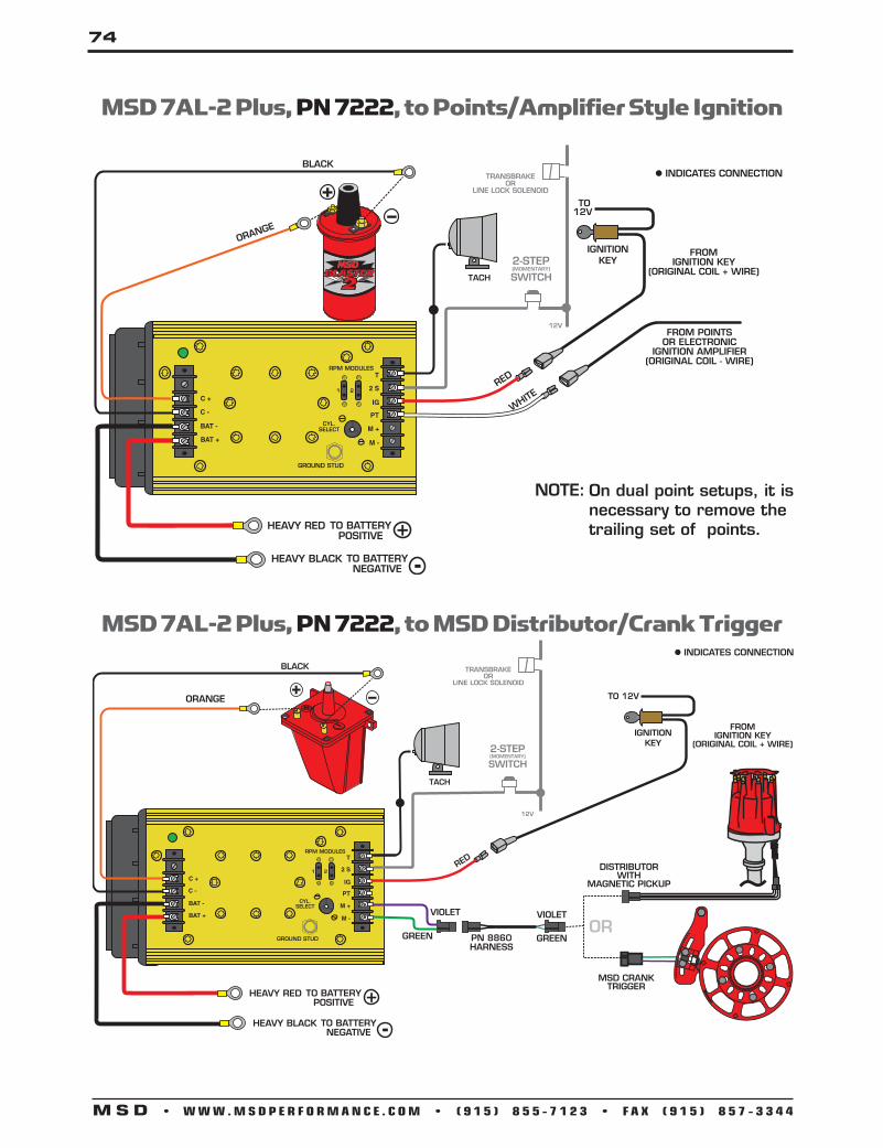
74
M S D • W W W . M S D P E R F O R M A N C E . C O M • ( 9 1 5 ) 8 5 5 - 7 1 2 3 • F A X ( 9 1 5 ) 8 5 7 - 3 3 4 4
On dual point setups, it is necessary to remove the trailing set of points.
NOTE:
DISTRIBUTOR
ORANGE
MSD 7AL-2 Plus, PN 7222, to Points/Amplifier Style Ignition
MSD 7AL-2 Plus, PN 7222, to MSD Distributor/Crank Trigger

75
M S D • W W W . M S D P E R F O R M A N C E . C O M • ( 9 1 5 ) 8 5 5 - 7 1 2 3 • F A X ( 9 1 5 ) 8 5 7 - 3 3 4 4
ORANGE BLACK
MSD 7AL-2 Plus, PN 7222, to MSD Distributor/Crank Trigger and Timing Control
Cylinder Select
This ignition can be used on 2, 4, 6 (even-fire) or 8-cylinder engines. The ignition is set for 8-cylinder operation. To program the unit for other engines, remove the one screw that holds the cover to reveal three wire loops (Figure 1). Cutting a wire loop determines the cylinder selection.
Cylinders Loops to Cut
8 None6 One4 Two2 Three Cut loops
Remove cap
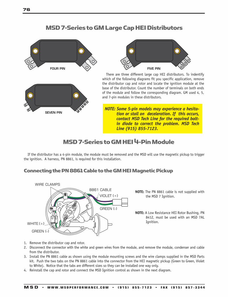
76
M S D • W W W . M S D P E R F O R M A N C E . C O M • ( 9 1 5 ) 8 5 5 - 7 1 2 3 • F A X ( 9 1 5 ) 8 5 7 - 3 3 4 4
MSD 7-Series to GM Large Cap HEI Distributors
MSD 7-Series to GM HEI 4-Pin Module
If the distributor has a 4-pin module, the module must be removed and the MSD will use the magnetic pickup to trigger the ignition. A harness, PN 8861, is required for this installation.
Connecting the PN 8861 Cable to the GM HEI Magnetic Pickup
1. Remove the distributor cap and rotor.2. Disconnect the connector with the white and green wires from the module, and remove the module, condenser and cable
from the distributor.3. Install the PN 8861 cable as shown using the module mounting screws and the wire clamps supplied in the MSD Parts
kit. Push the two tabs on the PN 8861 cable into the connector from the HEI magnetic pickup (Green to Green, Violet to White). Notice that the tabs are different sizes so they can be installed one way only.
4. Reinstall the cap and rotor and connect the MSD Ignition control as shown in the next diagram.
NOTE: The PN 8861 cable is not supplied with the MSD 7 Ignition.
NOTE: A Low Resistance HEI Rotor Bushing, PN 8412, must be used with an MSD 7AL Ignition.
There are three different large cap HEI distributors. To indentify which of the following diagrams fit you specific application, remove the distributor cap and rotor and locate the ignition module at the base of the distributor. Count the number of terminals on both ends of the module and follow the corresponding diagram. GM used 4, 5, and 7-pin modules in these distributors.
NOTE: Some 5-pin models may experience a hesita-tion or stall on deceleration. If this occurs, contact MSD Tech Line for the required bolt-in diode to correct the problem. MSD Tech Line (915) 855-7123.

77
M S D • W W W . M S D P E R F O R M A N C E . C O M • ( 9 1 5 ) 8 5 5 - 7 1 2 3 • F A X ( 9 1 5 ) 8 5 7 - 3 3 4 4
NOTE:
NOTE:
The stock rotor button must be replaced with an MSD Low Resis-tance Bushing, PN 8412.
The GM Ignition Module is removed and replaced with the MSD PN 8861 Wire Harness.
NOTE: NOTE: The stock rotor button must be replaced with an MSD Low Resistance Bushing, PN 8412.
Some 5-pin models may experience a hesitation or stall on decelera-tion. If this occurs, contact MSD Tech Line for the required bolt-in diode to correct the problem. MSD Tech Line (915) 855-7123.
MSD 7-Series to GM HEI 4-pin Module Distributor
MSD 7-Series to GM HEI with a5 or 7-pin Module (Amplifier Trigger)

78
M S D • W W W . M S D P E R F O R M A N C E . C O M • ( 9 1 5 ) 8 5 5 - 7 1 2 3 • F A X ( 9 1 5 ) 8 5 7 - 3 3 4 4
MSD 7-Series to Mallory Unilite
MSD 7-Series to Magnetic Pickup Triggers
DISTRIBUTOR
WHITENOT USED

79
M S D • W W W . M S D P E R F O R M A N C E . C O M • ( 9 1 5 ) 8 5 5 - 7 1 2 3 • F A X ( 9 1 5 ) 8 5 7 - 3 3 4 4
Installing an 7AL-3 Ignition Control This section covers the 7AL-3 Ignition Control. This ignition shares the same wiring to run the vehicle, but the 7AL-3 has several optional accessories that can be connected. The 7AL-2 Plus has a 2-Step rev limiter while the 7AL-3 has a 3-Step Rev Control along with other accessories which are explained on the next page. This ignition will install to most vehicles with a 12 volt electrical system and a distributor that is triggered with points, electronic amplifiers or magnetic pickups.
Operating Specifications
Wire Functions
Power Cables: The heavy Red connects to the battery positive (+) terminal. The heavy Black connects to the battery negative (-) terminal or other good engine ground. On the 7AL-3 these are called out as Batt+ and Batt -.
Red (IGN): Connects to a switched 12 volt source. Orange (COIL +): Connects to the positive (+) terminal of the coil. This is the only wire that makes
electrical contact with the coil (+) terminal. Black (COIL -): Connects to the negative (-) terminal of the coil. This is the only wire that makes
electrical contact with the coil negative terminal. White (PNTS): Connects to a points or amplifier trigger source. When this wire is used, the Magnetic
Pickup is not (Green and Violet). Violet (Mag +): These wires are routed into a 2-pin connector. It connects to the magnetic Green (Mag-): pickup of an MSD Distributor or Crank Trigger. The Violet is mag positive (+) and the Green
is negative (-). If this connector is used, the White wire will not be connected.
Operating Voltage:Current Requirements:
RPM Range:Spark Series Duration:
Primary Voltage:Energy Output Max:
Weight and Size:
WARNING: When using a capacitive discharge ignition control, there is high voltage present at the coil primary terminals. Never touch the coil or connect test equipment to these terminals.
WARNING: During installation, disconnect the battery. When disconnecting the battery always remove the negative cable first and install it last.
12-18 Volts 1 Amp per 1,000 rpm 14,000 w/14.4 Volts20° Crankshaft550 Volts160 Millijoules 4.75lbs, 8”x 3.75”x5.75”
PN 7230 - Red PN 7330 - Black
12-18 Volts 1 Amp per 1,000 rpm 14,000 w/14.4 Volts20° Crankshaft570 Volts160 Millijoules 4.75lbs, 8”x 3.75”x5.75”

80
M S D • W W W . M S D P E R F O R M A N C E . C O M • ( 9 1 5 ) 8 5 5 - 7 1 2 3 • F A X ( 9 1 5 ) 8 5 7 - 3 3 4 4
3-Step Rev Control Three rev limits can be set to be activated at different times. The over-rev rpm limit is active when the other limits are not activated. The Burnout or Launch rev limits are activated when 12 volts are applied to the corresponding terminal. If both limits are supplied with 12 volts, the Launch limit will override the Burnout limit.
NOTE: If no rpm module is installed, there will be no rev limit.
Start RetardWhen 12 volts are applied to this terminal, the timing will be retarded 25° until the engine reaches 1300 rpm where it deactivates. This can be connected to the starter solenoid to receive 12 volts when cranking or can be connected directly to 12 volts such as from the IGN terminal.
Retard Stages There are four stages of retard. The amounts are cumulative with a total of 20° being the max retard. On the 7230, each stage is activated when the corresponding terminal is REMOVED from ground. On the 7330, each stage is activated when the corresponding terminal is supplied with 12V. If a stage is not going to be used, a Zero degree module MUST be installed or the terminal(s) must be grounded.
RPM Activated Switch Two terminals are used to make up this circuit; RAS On/Off and Output RAS. The Output RAS terminal will supply a ground path to activate a circuit at a desired rpm (capable of up to 10 Amps). To use this circuit, 12 volts must be supplied to the RAS On/Off terminal.
7AL-3 Terminal Strips
MSD 7AL-3 Accessories
PN 7230 - Red
PN 7330 - Black

81
M S D • W W W . M S D P E R F O R M A N C E . C O M • ( 9 1 5 ) 8 5 5 - 7 1 2 3 • F A X ( 9 1 5 ) 8 5 7 - 3 3 4 4
MSD 7AL-3 with Rev Limiters
NOTE: The rev limiter activates when 12 Volts are supplied to the “Burnout” or “Launch” terminal.
DISTRIBUTOR
OR
MSD 7AL-3 to Primary Side of the Ignition to Points or Magnetic Pickup

82
M S D • W W W . M S D P E R F O R M A N C E . C O M • ( 9 1 5 ) 8 5 5 - 7 1 2 3 • F A X ( 9 1 5 ) 8 5 7 - 3 3 4 4
MSD 7AL-3 Using Retard Functions
NOTE: The retards will activate when removed from ground. The positive side of the solenoid will provide ground until activated.
NOTE: If a stage is not used, a ZERO Degree module must be installed or the terminal must be grounded.
MSD 7AL-3 Using Start Retard Function
NOTE: The 25° start retard activates when supplied with 12 Volts.
NOTE: Once the engine revs past 1,300 rpm the 25° start retard will not activate again until the ignition is shut off.

83
M S D • W W W . M S D P E R F O R M A N C E . C O M • ( 9 1 5 ) 8 5 5 - 7 1 2 3 • F A X ( 9 1 5 ) 8 5 7 - 3 3 4 4
MSD 7AL-3 Using RPM Activated Switchto Activate Nitrous
The OUTPUT RAS Terminal will supply a Ground at the selected RPM.
MSD 7AL-3 Using RPM Activated Switch for Shift Light
NOTE: A short jumper is supplied that can be used to provide a switched 12 Volts from the “IGN” terminal to the “RAS ON/OFF” terminal.
The OUTPUT RAS Terminal will supply a Ground at the selected RPM.

84
M S D • W W W . M S D P E R F O R M A N C E . C O M • ( 9 1 5 ) 8 5 5 - 7 1 2 3 • F A X ( 9 1 5 ) 8 5 7 - 3 3 4 4
NOTE: Solid core spark plug wires cannot be used with an MSD Ignition Control.
NOTE: A crank trigger is recommended to supply the input signal to the Power Grid Ignition System to ensure the most precise timing and rpm control.
MSD Power Grid System ControllerPN 7730
Operating Voltage:RPM Range:
Spark Series Duration:Primary Voltage:
Spark Energy:Weight and Size:
12-18 Volts, Negative Ground15,000 RPM with 14.4 Volts20° Crankshaft Rotation545-570 Volts200-220 Millijoules/Spark2.9 lbs., 7.5”L x 5”W x 2.25”H
Operating Specifications
RED - 12V SW OUTBLACK - BATTERY (-)
ORANGE - BATTERY 12VWHITE - POINTS OUT
MSDCAN MAG PICKUP
CONNECTOR
LEGACY IGNITION
SWITCHED IGNITION 12VGREEN - STEP 5LT. GREEN - STEP 4TAN - STEP 3VIOLET - STEP 2PINK - STEP 1
BLUE - LAUNCHLT. BLUE - BURN OUT
BRN/WHITE - RPM/TIME SWITCH
WHITE - POINTS IN
GRAY - TACHYELLOW - SHIFT LIGHT
V-NETCABLE
Power Grid System Controller Wiring

85
M S D • W W W . M S D P E R F O R M A N C E . C O M • ( 9 1 5 ) 8 5 5 - 7 1 2 3 • F A X ( 9 1 5 ) 8 5 7 - 3 3 4 4
BROWN 27 SHIELD RED 27 POWER OUT BLACK 30 MSD CAN LO BLACK 31 MSD CAN GND
Color PIN Function DescriptionBLACK 16 GROUND Ignition supply Ground wire. Connect to battery negative (-) terminal or engine
block.
ORANGE 17 BATT POWER Battery supply wire. Connects to battery positive (+) terminal or battery junction. NOTE: Do not connect to the alternator.
YEL/WHT 33 TRIGGER OUT Trigger output for electronic ignition amplifiers.
RED 34 POWER OUT On/Off switch wiring. This wire supplies switched 12V power to the 7720. (Not used when connecting to other MSD Ignitions)
RED 15 IGN 12V switched (Ignition)
GRAY 18 TACH Tach output. This wire will provide a 12 volt square wave tach signal.
WHITE 32 POINTS IN Trigger input from electronic ignition amplifiers, an ECU’s trigger or points.
YELLOW 1 SHIFT LIGHT Shift Light output wire. It can handle up to 3 amps continuous to ground when enabled.
LT BLUE 4 BURN OUT Burnout Rev Limit. When 12 volts are applied the Burnout Rev Limit is active. This disables the Slew Rate rev limits and overrides other rev limits. It is recommended to have this wire switched from an outside source, such as the crew chief before the burnout and while staging the car.
DK BLUE 21 LAUNCH This wire activates the Launch Rev Limit and is the main reset wire for several features of the Ignition. When 12 volts are applied to this wire it will activate the Launch Rev Limit. It also resets the shift light, the gear indicator to first gear, the Launch Retard curve and select Gear 1 curve. When 12 volts is removed, the Launch Time begins as does the Gear 1 curve. When 12 volts are applied the Slew Rate Rev limit will be disabled as well as the Time-Based Rev Limit curve.
PINK 22 STEP 1 Step 1 retard enabled with +12 volt input AND above Step 1 Rpm value OR Gear 2 Select.
VIOLET 5 STEP 2 Step 2 retard enabled with +12 volt input AND above Step 2 Rpm value OR Gear 3 Select.
TAN 23 STEP3 Step 3 retard enabled with +12 volt input AND above Step 3 Rpm value OR Gear 4 Select.
LT GREEN 6 STEP4 Step 4 retard enabled with +12 volt input AND above Step 4 Rpm value OR Gear 5 Select.
GREEN 10 STEP5 Step 5 retard enabled with +12 volt input AND above Step 5 Rpm value OR spool rev limiter.
BRN/WHT 19 RPM SW RPM/Time switch output wire. It can switch up to 3 amps continuous to ground when enabled.
YELLOW 7 RELAY LO Network Ignition Mode: Cam sync output to Racepak systems for individual cylinder timing.
YELLOW 24 RELAY HI Legacy Ignition Mode: Rev limiter output to legacy ignition..
GREEN 8 MAG- This is a magnetic pickup, 2-pin connector. Plugs into an MSDVIOLET 9 MAG+ Distributor or Crank Trigger pickup. Violet is positive, Green is negative.BROWN 25 SHIELD NOTE: When this connector is used, the white POINTS IN wire is not connected.
Brown connects to ground.
WHITE 11 VNET HI Communicates data acquisition information with RacePak system.BLACK VNET LO Only used to plug into VNet. RED 13 MSD CAN HI Supplies 12V switched power to add on module units. Also communicates
between modules and Power Grid System Controller. This connector is only used with modules added onto the system. This is for the MSD CAN-Bus accessories. It is only used when adding Power Grid Modules to the system. The Hub Connector, PN 7769, is required.
4-Pin Connector (to PN 7720 or Power Cable if not used
with PN 7720)
LOOSEWIRES
2-Pin Connector (Legacy)
3-Pin Connector
Racepak Assembly
6-Pin Connector (to Hub/Modules)
LeadingGroup
or
Wiring Features

86
M S D • W W W . M S D P E R F O R M A N C E . C O M • ( 9 1 5 ) 8 5 5 - 7 1 2 3 • F A X ( 9 1 5 ) 8 5 7 - 3 3 4 4
MSDCAN
LEGACY IGNITION
SWITCHED IGNITION 12V
GREEN - STEP 5
LT. GREEN - STEP 4
TAN - STEP 3
VIOLET - STEP 2
PINK - STEP 1
BLUE - LAUNCHLT. BLUE - BURN OUT
BRN/WHITE - RPM/TIME SWITCH
WHITE - POINTS IN
GRAY - TACHYELLOW - SHIFT LIGHT
GREENGREEN
VIOLETVIOLET
SUPPLIED JUMPER
ORANGE
BLACK
RED
WHITE
BATTERY
BATTERY
ORANGE
BLACK
+
-
ORANGE
BLACK
+
-
V-NETCABLE
Power Grid System Controller to MSD 8-Plus
RED - 12V SW OUTBLACK - BATTERY (-)
ORANGE - BATTERY 12VWHITE - POINTS OUT
MSDCAN
MAG PICKUPCONNECTOR
LEGACY IGNITION
SWITCHED IGNITION 12VGREEN - STEP 5LT. GREEN - STEP 4TAN - STEP 3VIOLET - STEP 2PINK - STEP 1
BLUE - LAUNCHLT. BLUE - BURN OUT
BRN/WHITE - RPM/TIME SWITCH
WHITE - POINTS IN
GRAY - TACHYELLOW - SHIFT LIGHT
PN 7720IGNITION
ORANGE
BLACK
+
+
-
-
TO BATTERY POSITIVE
TO BATTERY NEGATIVE
HEAVY RED
HEAVY BLACK
V-NETCABLE
VNET Connector
4-Pin Deutsch connector
3-Pin Deutsch connector
4-Pin Deutsch connector Female
VN7730 HarnessConnectors
Mating Pieces If any
3-Pin Deutsch connector Female
Power Grid System Wiring

87
M S D • W W W . M S D P E R F O R M A N C E . C O M • ( 9 1 5 ) 8 5 5 - 7 1 2 3 • F A X ( 9 1 5 ) 8 5 7 - 3 3 4 4
V-NETCABLE
MSDCAN
LEGACYIGNITION
SWITCHED IGNITION 12V
GREEN - STEP 5
LT. GREEN - STEP 4
TAN - STEP 3
VIOLET - STEP 2
PINK - STEP 1
BLUE - LAUNCH
LT. BLUE - BURN OUT
BRN/WHITE RPM/TIME SWITCH
WHITE - POINTS IN (NOT USED)
GRAY - TACH
YELLOW - SHIFT LIGHT
GREENGREEN
VIOLETVIOLET
REDNOT USED
WHITE
ORANGE BLACK
MSD RPMRECEPTICAL
VIOLET
NOT USED
IGNITION
BLACKRED
CHASSISGROUND
TO GROUNDON CYLINDER HEAD
12V
12V
12V
12V
SHIFT OR FUELSOLENOID
LINE LOCK SWITCH
TRANSBRAKE OR CLUTCH SWITCH
LT. BLUE - BURN OUT
+-
BATTERYPOSITIVE
BATTERYNEGATIVE
GREEN
WHITEVIOLET
VIOLETBARE BLACK
OR
3-WIRE LEAHY CURVED CRANK TRIGGER
MAG PICKUPCONNECTOR
Power Grid System Controller to Pro-Mag

88
M S D • W W W . M S D P E R F O R M A N C E . C O M • ( 9 1 5 ) 8 5 5 - 7 1 2 3 • F A X ( 9 1 5 ) 8 5 7 - 3 3 4 4
MSDCAN
LEGACY IGNITION
SWITCHED IGNITION 12V
GREEN - STEP 5
LT. GREEN - STEP 4
TAN - STEP 3
VIOLET - STEP 2
PINK - STEP 1
BLUE - LAUNCHLT. BLUE - BURN OUT
BRN/WHITE - RPM/TIME SWITCH
WHITE - POINTS IN (NOT USED)
GRAY - TACHYELLOW - SHIFT LIGHT
GREENGREEN
VIOLETVIOLET
INDICATES CONNECTION
REDBLACK
RED
WHITE
ORANGE BLACK
TACHNOTUSED
MSD RPMRECEPTICAL
V-NETCABLE
ORANGE
BLACK
+
+
-
-
BATTERYPOSITIVE
BATTERYNEGATIVEMultiple
Spark Discharge
AUTOTRONIC CONTROLS CORPORATION
SERIAL NO..IGNITION
PART NO.
PN 8253
Power Grid System Controller to MSD 6AL
89
M S D • W W W . M S D P E R F O R M A N C E . C O M • ( 9 1 5 ) 8 5 5 - 7 1 2 3 • F A X ( 9 1 5 ) 8 5 7 - 3 3 4 4
NOTE: Solid core spark plug wires cannot be used with an MSD Ignition Control.
MSD Power Grid 7 Ignition ControlPN 7720
WiringGeneral Wiring InformationWire Length: All of the wires of the MSD Ignition may be shortened as long as quality connectors are used or soldered in place. To lengthen the wires, use one size bigger gauge wire (10 gauge for the power leads and 16 gauge for the other wires) with the proper connections. All connections must be soldered and sealed.
Grounds: A poor ground connection can cause many frustrating problems. When a wire is specified to go to ground, it should be connected to the battery negative terminal, engine block or chassis. There should always be a ground strap between the engine and the chassis. Always securely connect the ground wire to a clean, paint free metal surface.
Noise Capacitor: MSD offers a Noise Capacitor or Filter to help eliminate EMI noise. This capacitor, PN 8830, will also protect the MSD and accessories from voltage and current spikes.
Routing WiresThe MSD wires should be routed away from direct heat sources such as exhaust manifolds and headers and any sharp edges. The trigger wires should be routed separate from the other wires and spark plug wires. It is best if they are routed along a ground plane such as the block or firewall which creates an electrical shield.
WARNING: The MSD Power Grid Ignition is a capacitive discharge ignition. High voltage is present at the coil primary terminals. Do not touch the coil or connect test equipment to the terminals.
The Power Grid 7 Ignition Control was specifically designed to pair with the Power Grid System Controller, PN 7730. This Ignition system is designed for racing applications; it is not for sale for legal use on highways.
Operating Specifications
Operating Voltage:RPM Range:
Spark Series Duration:Primary Voltage:
Spark Energy:Weight and Size:
12-18 Volts, Negative Ground15,000 RPM with 14.4 Volts20° Crankshaft Rotation545-570 Volts200-220 Millijoules/Spark2.9 lbs., 7.5”L x 5”W x 2.25”H

90
M S D • W W W . M S D P E R F O R M A N C E . C O M • ( 9 1 5 ) 8 5 5 - 7 1 2 3 • F A X ( 9 1 5 ) 8 5 7 - 3 3 4 4
Power Grid 7 Ignition Control Wiring
ORANGE
BLACK
+
+
-
-
TO BATTERY POSITIVE
TO BATTERY NEGATIVE
REDBLACK
ORANGEWHITE
HEAVY RED
HEAVY BLACK
CONTROLLER WIRES.SEE PN 7730INSTRUCTIONS
WiringDeutsch Male 4-Pin Connector
12ga Red Battery Positive – This wire connects directly to the battery positive (+) terminal or to a positive battery junction or the positive side of the starter solenoid.
12ga Black Battery Negative – This wire connects to a good ground, either at the battery negative (-) terminal or to the engine.
16ga Orange Coil Positive – This wire connects to the positive (+) terminal of the coil. This is the only wire that makes electrical contact with the coil positive terminal.
16ga Black Coil Negative – This wire connects to the negative (-) terminal of the coil. This is the only wire that makes electrical contact with the coil negative terminal.
Deutsch Female 4-Pin Connector
18ga Red Ignition – This wire is switched 12 volts to turn the ignition and modules on and off.
18ga White Trigger Input – This wire is used to communicate the timing signal from the System Controller to the ignition.
18ga Black Ground – This wire supplies the ground for the System Controller. This connects internally with the ground from the heavy Black wire in the first connector.
18ga Orange Battery – This wire supplies power through the Power Grid Ignition to the System controller.
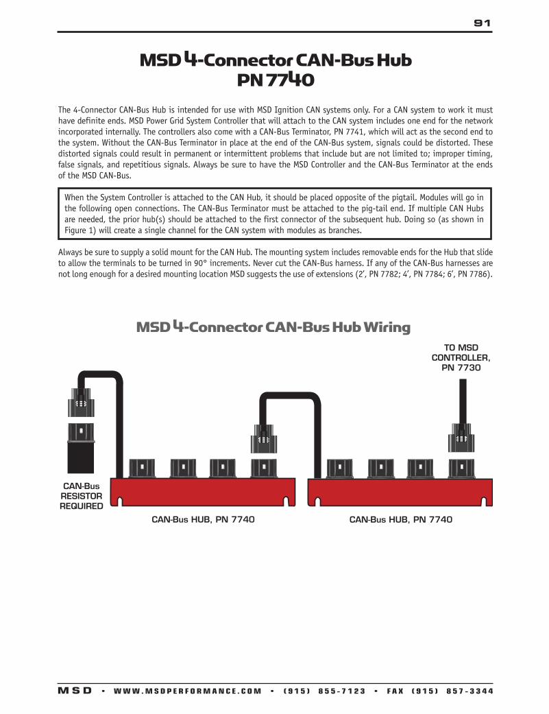
91
M S D • W W W . M S D P E R F O R M A N C E . C O M • ( 9 1 5 ) 8 5 5 - 7 1 2 3 • F A X ( 9 1 5 ) 8 5 7 - 3 3 4 4
MSD 4-Connector CAN-Bus HubPN 7740
CAN-Bus HUB, PN 7740
CAN-BusRESISTORREQUIRED
CAN-Bus HUB, PN 7740
TO MSDCONTROLLER,
PN 7730
MSD 4-Connector CAN-Bus Hub Wiring
The 4-Connector CAN-Bus Hub is intended for use with MSD Ignition CAN systems only. For a CAN system to work it must have definite ends. MSD Power Grid System Controller that will attach to the CAN system includes one end for the network incorporated internally. The controllers also come with a CAN-Bus Terminator, PN 7741, which will act as the second end to the system. Without the CAN-Bus Terminator in place at the end of the CAN-Bus system, signals could be distorted. These distorted signals could result in permanent or intermittent problems that include but are not limited to; improper timing, false signals, and repetitious signals. Always be sure to have the MSD Controller and the CAN-Bus Terminator at the ends of the MSD CAN-Bus.
When the System Controller is attached to the CAN Hub, it should be placed opposite of the pigtail. Modules will go in the following open connections. The CAN-Bus Terminator must be attached to the pig-tail end. If multiple CAN Hubs are needed, the prior hub(s) should be attached to the first connector of the subsequent hub. Doing so (as shown in Figure 1) will create a single channel for the CAN system with modules as branches.
Always be sure to supply a solid mount for the CAN Hub. The mounting system includes removable ends for the Hub that slide to allow the terminals to be turned in 90° increments. Never cut the CAN-Bus harness. If any of the CAN-Bus harnesses are not long enough for a desired mounting location MSD suggests the use of extensions (2’, PN 7782; 4’, PN 7784; 6’, PN 7786).

92
M S D • W W W . M S D P E R F O R M A N C E . C O M • ( 9 1 5 ) 8 5 5 - 7 1 2 3 • F A X ( 9 1 5 ) 8 5 7 - 3 3 4 4
NOTE: The MSD CAN-Bus Hub, PN 7740, is required to connect the PN 7751.NOTE: The CAN-Bus technology used in the Power Grid Ignition System requires a resistor at both ends in order to function
properly. Do not throw away the Resistor cap, PN 7741, that comes attached to the Power Grid System Controller, PN 7730! It should be attached to the pig-tail of the CAN-Bus Hub, PN 7740, when the Hub is used to add modules.
The Manual Launch Control Module, PN 7751, is designed exclusively for use with the Power Grid System Controller, PN 7730. The Module provides racers an easy way to make adjustments to the launch rpm, and the the shift light intensity without connecting a PC. The Module also displays the engine timing.
Mount the Manual Launch Control Module in a position that allows for easy reach and adjustments. Also, make sure the harness of the module reaches the CAN-Bus Hub. Plug the connector from the Launch Module into an available CAN-Bus receptor on the Hub connector.
NOTE: Do not cut the wires to shorten the harness. If a longer harness is needed, MSD offers extension harnesses (2’, PN 7782; 4’, PN 7784; 6’, PN 7786).
OperationThe Launch Module has five basic settings that can each be selected and adjusted using the module’s joystick. Push the joystick in (as a button) to select a setting to be edited or to confirm changes after a setting is changed. To scroll through setting options the joystick should be pushed horizontally (left or right). To edit a selected setting, use vertical motions with the joystick. If a setting is selected to be changed and no action is taken in five seconds it will automatically deselect and revert to the setting that was initially programmed.
Multiple Manual Launch Control Modules can be plugged into the same system. If one is desired within reach of the driver and another is to be easily accessible to the crew, both will display real time changes. Launch RPM: This selection controls the Launch Rev Limiter setting. Using the module the Launch Limiter can be changed
in 50 rpm increments from 0-10,000 rpm.Shift Light: This controls the shift light intensity. The setting is adjustable from 0-100% power 5% at a time. Timing: This displays the engine’s timing as set by the 7730 in real time.* This is a Read Only feature.Contrast: The screen on the Launch Module can be controlled for easier reading depending on lighting conditions.Rotate: The screen on the Launch Module can be rotated 180° if needed depending on its mounting position.
*NOTE: If the Maximum Timing Reference is not properly set within MSD View the 7730 may read and prescribe incorrect engine timing. Always ensure than the Max Timing Reference matches the timing where the crank trigger is set.
MSD Manual Launch ControlPN 7751
RED - 12V SW OUTBLACK - BATTERY (-)
ORANGE - BATTERY 12VWHITE - POINTS OUT
MAG PICKUPCONNECTOR
LEGACY IGNITION
SWITCHED IGNITION 12VGREEN - STEP 5LT. GREEN - STEP 4TAN - STEP 3VIOLET - STEP 2PINK - STEP 1
BLUE - LAUNCHLT. BLUE - BURN OUTBRN/WHITE - RPM/TIME SWITCH
WHITE - POINTS IN
GRAY - TACHYELLOW - SHIFT LIGHT
V-NETCABLE
LAUNCH RPM4125
CAN-BusRESISTORREQUIRED
CAN-Bus HUB, PN 7740 REQUIRED
LEFT, RIGHT - SCROLL OPTIONPUSH IN - SELECTUP, DOWN - EDIT
SCREEN COLORS WILL MATCH THE LED ON THE PN7730.
Manual Launch Control Wiring
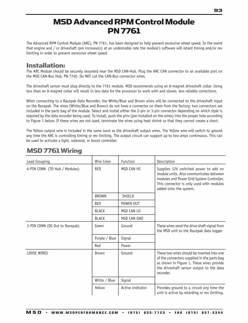
93
M S D • W W W . M S D P E R F O R M A N C E . C O M • ( 9 1 5 ) 8 5 5 - 7 1 2 3 • F A X ( 9 1 5 ) 8 5 7 - 3 3 4 4
MSD Advanced RPM Control ModulePN 7761
The Advanced RPM Control Module (ARC), PN 7761, has been designed to help prevent excessive wheel speed. In the event that engine and / or driveshaft rpm increase(s) at an undesirable rate the module’s software will retard timing and/or rev limiting in order to prevent excessive wheel speed.
Installation:The ARC Module should be securely mounted near the MSD CAN-Hub. Plug the ARC CAN connector to an available port on the MSD CAN-Bus Hub, PN 7740. Do NOT cut the CAN-Bus connector wires.
The driveshaft sensor must plug directly to the 7761 module. MSD recommends using an 8-magnet driveshaft collar. Using less than an 8-magnet collar will result in less data for the processor to work with and slower, less reliable corrections.
When connecting to a Racepak Data Recorder, the White/Blue and Brown wires will be connected to the driveshaft input on the Racepak. The wires (White/Blue and Brown) do not have a connector on them from the factory; two connectors are included in the parts bag of the module. Select and install either the 2-pin or 3-pin connector depending on which style is required by the data recorder being used. To install, push the pins (pre-installed on the wires) into the proper hole according to Figure 1 below. If these wires are not used, terminate the wires using heat shrink so that they cannot create a short.
The Yellow output wire is included in the same loom as the driveshaft output wires. The Yellow wire will switch to ground any time the ARC is controlling timing or rev limiting. The output circuit can support up to two amps continuous. This can be used to activate a light, solenoid, or boost controller.
MSD 7761 WiringLead Grouping Wire Color Function Description 6-PIN CONN (TO Hub / Modules) RED MSD CAN HI Supplies 12V switched power to add on
module units. Also communicates between modules and Power Grid System Controller. This connector is only used with modules added onto the system.
BROWN SHIELD RED POWER OUT BLACK MSD CAN LO BLACK MSD CAN GND 3-PIN CONN (DS Out to Racepak) Green Ground These wires send the drive shaft signal from
the MSD unit to the Racepak data logger.
Purple / Blue Signal
Red Power LOOSE WIRES Brown Ground These two wires should be inserted into one
of the connectors supplied in the parts bag as shown in Figure 1. These wires provide the driveshaft sensor output to the data recorder.
White / Blue Signal Yellow Active Indicator Provides ground to a circuit any time the
unit is active by retarding or rev limiting.

94
M S D • W W W . M S D P E R F O R M A N C E . C O M • ( 9 1 5 ) 8 5 5 - 7 1 2 3 • F A X ( 9 1 5 ) 8 5 7 - 3 3 4 4
MSD Boost Retard Module for the Power Grid System
PN 7762The Boost Retard Module for the Power Grid System allows for engine timing changes based on pressure in the manifold. The Boost Retard Module also lets the user set several other functions including an Over-boost setting, a Boost Pressure Switch and Data Acquisition of the manifold pressure.
Over-Boost: Allows the user to set an over-boost limit that will disable the ignition if that limit is exceeded.
Boost Pressure Switch: There is an Orange output wire that switches to ground when the desired boost pressure is reached. The Orange wire can sync 2 amps of current (continuous) to ground. When higher current is required, use of a relay with the Orange wire is needed.
Data Acquisition: The Module provides data recording of the manifold pressure for boost or vacuum. All Power Grid Modules work through MSD’s CAN-Bus system. The Power Grid Modules are plug and play installations but may require extension harnesses for remote wiring. NOTE: Do NOT cut the wires to the CAN-Bus Harness. In the event an extension harness is needed to mount the unit in the desired location MSD offers the following extension harnesses-
• 2’CAN-BusextensionPN7782• 4’CAN-BusextensionPN7784• 6’CAN-BusextensionPN7786
The Boost Retard Module utilizes a ¼” Camozzi (push lock) pneumatic fitting. The fitting is not interchangeable. Attempting to change the fitting will damage the circuit board and is not recommended by MSD.
MSDCAN
ACTIVEOUTPUT(The wireis groundedwhen the ARCmodule is in control.)
3-PIN
3-PIN
USERCONFIGURABLE
INPUT(PULSES PER DRIVE
SHAFT REV)
HALLEFFECT SENSOR
USERCONFIGURABLE
OUTPUT(PULSES PER DRIVE
SHAFT REV)
ARC MODULE
RPMCONTROL
ADVANCE
PN 7761
EFFECT RPMSHAFT SENSORPN:800-SS-MSC-5
SIGNALNOT USED
NOT USED
2-PINSIGNAL
RACEPAK HALL
SIGNAL
NOT USED
MSD 7761 Wiring

95
M S D • W W W . M S D P E R F O R M A N C E . C O M • ( 9 1 5 ) 8 5 5 - 7 1 2 3 • F A X ( 9 1 5 ) 8 5 7 - 3 3 4 4
Boost Activation SwitchThe Orange wire can be used to activate a device based on boost pressure. If the device requires more than 2-amps, a relay is required. Figure 5 shows a typical example.
NOTE: RELAY NOT SUPPLIED.
ORANGE
(SWITCHES TO GROUND)
Wiring
Wire Grouping Wire Color Function Description
6-PIN CONN RED MSD CAN HI BROWN SHIELD RED POWER OUT BLACK MSD CAN LO Black MSD CAN GND Loose Wire Orange SWITCHED GND
Supplies 12V switched power to add on module units. Also communicates between modules and Power Grid System Controller. This connector is used only with Modules added to the system.
This wire is normally open to ground. Once activated, this wire will sync 2A of current to ground. Use of a relay is recommended with this wire (Figure 1).
(To Hub/Modules)

96
M S D • W W W . M S D P E R F O R M A N C E . C O M • ( 9 1 5 ) 8 5 5 - 7 1 2 3 • F A X ( 9 1 5 ) 8 5 7 - 3 3 4 4
MSD Boost Control ModulePN 7763
InstallationNote: Use of a pressure regulator is required. Adjust the CO2 bottle pressure to no more than 20psi above the maximum
wastegate target pressure. MSD recommends Camozzi fittings throughout the air pressure system.
Wiring1. Mount the Boost Control Module with the supplied hardware.2. Plug the six pin MSD CAN connector from the Boost Control Module into a free port on the MSD CAN-Bus Hub PN
7740.3. The orange wire switches to ground when active. Use a relay to activate devices that consume more than 2 amps.4. Route all wires away from heat sources.5. Assemble the connectors. NOTE: The solenoids are not polarity sensitive.6. Connect the red and white wires to the Pressure IN solenoid.7. Connect red and yellow wires to the Pressure OUT (VENT) solenoid.
SOLENOID
GROUND
12V
12V
TO BOOST/ENGINEMAP
PRESSURE& VENT
SOLENOIDS
MSDCAN
CAMOZZIFITTINGS
TOCONTROLPORT ONWASTEGATESWITCHING
GROUND
PN 7763
BOOSTCONTROLMODULE
WASTEGATEMANIFOLD
Wire Grouping Wire Color Function Description
6 PIN CONN RED MSD CAN HI
BROWN SHIELD
RED POWER
BLACK MSD CAN LO
BLACK MSD CAN GND
Single Wire ORANGE SWITCHED GND
Solenoid Connector RED 12V Control wires for the Pressure IN Solenoid.
WHITE SWITCHED GND
Solenoid Connector RED 12V Control Wires for the Vent OUT Solenoid.
YELLOW SWITCHED GND
Supplies 12v switched power to add on modules on CAN-Hub. Allows communication with the Power Grid System Control. This connector is used only with Modules added to the CAN-Hub System.
Normally open and will switch to ground once activated (2A max). Use of a relay is required for higher current applications

97
M S D • W W W . M S D P E R F O R M A N C E . C O M • ( 9 1 5 ) 8 5 5 - 7 1 2 3 • F A X ( 9 1 5 ) 8 5 7 - 3 3 4 4
Dual Wastegate Plumbing, PN 7763
Single Wastegate Plumbing, PN 7763

98
M S D • W W W . M S D P E R F O R M A N C E . C O M • ( 9 1 5 ) 8 5 5 - 7 1 2 3 • F A X ( 9 1 5 ) 8 5 7 - 3 3 4 4
MSD Boost Control Module External MapPN 77631
InstallationNote: Use of a pressure regulator is required. Adjust the CO2 bottle pressure to no more than 20psi above the maximum
wastegate target pressure. MSD recommends Camozzi fittings throughout the air pressure system.
Wiring1. Mount the Boost Control Module with the supplied hardware.2. Plug the six pin MSD CAN connector from the Boost Control Module into a free port on the MSD CAN-Bus Hub PN 7740.3. The orange wire switches to ground when active. Use a relay to activate devices that consume more than 2 amps.4. Route all wires away from heat sources.5. Assemble the connectors. NOTE: The solenoids are not polarity sensitive.6. Connect the red and white wires to the Pressure IN solenoid.7. Connect red and yellow wires to the Pressure OUT (VENT) solenoid.
Wire Grouping Wire Color Function Description6 PIN CONN RED MSD CAN HI BROWN SHIELD RED POWER BLACK MSD CAN LO BLACK MSD CAN GND Single Wire ORANGE SWITCHED GND
Solenoid Connector RED 12V Control wires for the Pressure IN Solenoid. WHITE SWITCHED GND Solenoid Connector RED 12V Control Wires for the Vent OUT Solenoid. YELLOW SWITCHED GNDMAP Sensor ORANGE 5V Plug in for Wastegate MAP Sensor.Connector BROWN GROUND BLUE SIGNALMAP Sensor ORANGE 5V Plug in for Manifold MAP Sensor.Connector BROWN GROUND GREEN SIGNAL
Supplies 12v switched power to add on modules on CAN-Hub. Allows communication with the Power Grid System Control. This connector is used only with Modules added to the CAN-Hub System.(Figure 1)
Normally open and will switch to ground once activated (2A max). Use of a relay is required for higher current applications (Figure 3)

99
M S D • W W W . M S D P E R F O R M A N C E . C O M • ( 9 1 5 ) 8 5 5 - 7 1 2 3 • F A X ( 9 1 5 ) 8 5 7 - 3 3 4 4
Single Wastegate Plumbing, PN 77631

100
M S D • W W W . M S D P E R F O R M A N C E . C O M • ( 9 1 5 ) 8 5 5 - 7 1 2 3 • F A X ( 9 1 5 ) 8 5 7 - 3 3 4 4
Dual Wastegate Plumbing, PN 77631

101
M S D • W W W . M S D P E R F O R M A N C E . C O M • ( 9 1 5 ) 8 5 5 - 7 1 2 3 • F A X ( 9 1 5 ) 8 5 7 - 3 3 4 4
Installing an MSD Programmable Digital-7Ignition Control
This section covers the basic wiring and accessories of the MSD Programmable Digital-7 Series Ignition, PN 7530T, PN 75301, PN 7535, and PN 7531. These are powerful ignitions with a list of programmable timing and rpm features. The ignitions can be programmed with a PC or with MSD’s hand held Programmer/Monitor. They can be triggered by points, amplifiers, magnetic pickups or the trigger output of an ECU for fuel injection systems. Pro-Data+ software can be downloaded for free at msdignition.com.
Operating Specifications Operating Voltage: +12-18 volts Current Requirements: 1.1 Amp per 1,000 RPM RPM Range: 12,500 rpm with 14.4 volt supply Spark Duration: 20° Crankshaft Primary Voltage Output: 535 Volts Spark Energy Output: 190 milliJoules Per Spark Weight and Size: 4.7lbs., 9.5”L x 4.5”W x 2.2”H
NOTE: The Pro Power HVC Coil, PN 8251 or Pro Power HVC II, PN 8261, are recommended.
Programmable Digital-7 Ignition Options
Several versions of the Programmable 7-Series Ignitions have been offered. This chart shows what features are available in each model.
PN 7
535
PN 7
530T
PN 7
5301
PN 7
531
PN 7
535
PN 7
530T
PN 7
5301
PN 7
531
RETARDS Start Retard X X X X Launch Retard (based on time) X X X X 3-Step Retards (ramp on/off) X X X X
OUTPUTS Activation Switch by RPM X X X X by Time X X X X by PSI X X Sequential Shift Light X X X X Staging Light X X X X Tach Output Configurable to Trigger/Timing X X X X Configurable Cam Sync or Limiter output X X X X
SENSOR Configurable 1, 2 & 3-Bar X X TUNING Real Time Graphical Display for Engine Monitor (with Laptop) X X X X
TRIGGER INPUTS Magnetic Pickup X X X X Square Wave (Points, 12V Sq.) X X X X REV LIMITERS Over-rev Limiter X X X X Launch Limiter X X X X Burn Out Limiter X X X X Spool Limiter (Turbo) X X Slew Rate Limiter (Per Gear) X Auto Learning Limiter X X X X RPM/Time Based Limiter Map X Time Rev Limiter (NHRA Req.) X X Traction Control Detection (NHRA Req.) X X TIMING Individual Gear Timing Map X X X X Boost Timing Map X X Individual Cylinder Timing X X X X
DATA LOGGING Ignition Acquisition X X RETARDS

102
M S D • W W W . M S D P E R F O R M A N C E . C O M • ( 9 1 5 ) 8 5 5 - 7 1 2 3 • F A X ( 9 1 5 ) 8 5 7 - 3 3 4 4
Programmable Wire OperationThis wire connects directly to the battery positive (+) terminal or a positive battery junction such as the starter solenoid. NOTE: Do not connect to the alternator.
This wire connects to a good ground, either at the battery negative (-) terminal or to the engine.
Heavy Red
Heavy Black
Red
Cam SyncLight Blue andLight GreenFiber OpticConnection
Accessories
Dark Blue
Light Blue
Spool-UpPN 7535 and PN 7531 Only
Pink
Violet
Tan
Yellow
Brown/White
This wire is responsible for turning the MSD On and Off. Connects to a switched 12 volt source such as the ignition key or switch.
This wire connects to the coil positive (+) terminal. This is the ONLY wire that makes electrical contact with the positive coil terminal.
This wire connects to the coil negative (-) terminal. This is the ONLY wire that makes electrical contact with the negative coil terminal.
There are two circuits that can be used to trigger the MSD Ignition; a Points circuit (the White wire) and a Magnetic Pickup circuit (the Green and Violet wires). The two circuits will never be used at the same time.
This wire is used to connect to breaker points, electronic ignition amplifier output or to the trigger output of the ECU. When this wire is used, the Magnetic Pickup connector is not used.These wires are routed together in one harness as the magnetic pickup connector. The connector plugs directly into an MSD distributor or crank trigger. It will also connect to aftermarket pickups. The Violet wire is positive (+) and the Green wire is negative (-). When these wires are used, the White wire is not.
This 2-pin connector plugs into a Cam Sync Sensor to indicate when the number one cylinder is triggered. The wires are Light Blue and Light Green.
This is where the fiber optic cable of the PN 7555 Inductive Sync Kit connects to take advantage of the Individual Cylinder Management feature. This must be covered when using the 2-pin cam sync input.
Launch Limit. When 12 volts are applied, this wire activates several features includ-ing; Launch rev limit, Launch Retard value, Launch Timing Curve and will reset the Shift Light sequence to 1st gear.
Burnout Limit. This wire activates the Burnout rev limit when 12 volts are applied.
When the Dark Blue and Light Blue wires are appled to 12 volts at the same time, a fourth rev limit is activated. This limit is to spool up a turbo during the burnout. When both the Dark Blue and Light Blue RevLimit wires are at +12 volts then the Spool RevLimit is active.
Step 1 Retard. This wire activates the first retard stage when it is applied to 12 volts. When 12 volts is removed the retard is deactivated.
Step 2 Retard. This wire activates the second retard stage when it is applied to 12 volts. When 12 volts is removed the retard is deactivated.
Step 3 Retard. This wire activates the third retard stage when it is applied to 12 volts. When 12 volts is removed the retard is deactivated.
Shift Light activation wire. Supplies ground to activate a light.
RPM Activation Switch. This wire will supply a ground to complete a circuit at a desired rpm. It will handle up to 3 amps continuous.
Orange
Black
Trigger Wires
White
Violet and Green(Magnetic Pickup Connector)
Yellow/Yellow Output for data acquisition or fuel controls. Note, only two wires are used.
PN 7535 and PN 7531 Only 3-Pin Connector, MAP SensorConnector Connects to an external MAP or gauge pressore sensor.
+5 volt supply
Ground
Map Signal
Brown/Violet
Brown/Yellow
Dark Brown

103
M S D • W W W . M S D P E R F O R M A N C E . C O M • ( 9 1 5 ) 8 5 5 - 7 1 2 3 • F A X ( 9 1 5 ) 8 5 7 - 3 3 4 4
Programmable Features The following explains the programmable features of the PN 7535, PN 7530T, PN 75301 and PN 7531 Ignition. The features are listed in the same order that they show on the Data Editor list in the software. Note that all of the retard amounts are cumulative and the maximum amount of retard is 30°. As indicated, not all features are available in each model.
Rev Limits Up to three different rev limits can be programmed in 100 rpm increments from 2,000 – 12,500.
RevBurn: Burnout Rev Limit. This limit is activated when 12 volts are applied to the Light Blue wire. It is adjust-able from 2,000 to 12,500 rpm. Note that the Slew Rev Limiter is disabled by the Burnout Limit.
RevMax: Max Speed Rev Limit. This is the overrev limit and is active whenever the Launch and BurnOut limits are off. PN 7531 only - OutCam: Select either a Cam Sync output or a Rev Limiting output that can be used with MSD components that use rpm modules for the rev limit, or data acquisition units.
RPM: Adjustable in 100 rpm increments from 2,000 – 12,500.
PN 7531 only - AdjOff: This program enables an automatic compensating rev limiter that will correct trigger input offsets and variables. It can be turned On or Off. RevLaunch: Launch Rev Limit. This limit is activated when 12 volts are applied to the Dark Blue wire. It is adjust-able from 2,000 to 12,500 rpm.
PN 7531 and PN 7535 only - Spool-Up: This program gives turbo cars a fourth rev limit to help the engine spool boost pressure prior to the burnout. It is active when both the Light and Dark Blue wires are applied to 12 volts at the same time. It is adjustable in 100 rpm increments from 2,000- 12,500. Default is 3,000 rpm.
Start Retard Program an amount of retard that will occur while the engine is cranking. This helps reduce the load on the starter for easier cranking. It is adjustable from 0° - 25° in 1° increments. This is an automatic feature and will enable below 500 rpm and will deactivate when the engine reaches above 800 rpm. Default is 10°.
Launch Retard This is the time based retard ramp. It can be programmed from 0°-15° in 0.1° increments and from 0-2.5 seconds. When the Dark Blue Launch/Reset wire is connected to 12 volts, this retard value is activated. When 12 volts are removed from the Dark Blue wire, the timer begins to ramp the retard value back to 0° over the programmed time. Once the time is over, the retard will not be activated again.
Step Retards There are three step retards that are controlled through three corresponding activation wires or through rpm. They can also have an rpm point that the engine must reach before the retard becomes active. (A minimum rpm can also be programmed that must be reached before a step becomes active.) A time based ramp can be programmed to gradually bring the retard to its full on amount, or to ramp the retard amount out (back to no retard) from its setting.
Step 1 – Pink Step 2 – Dark Brown Step 3 – Tan
Activation through Wiring: Each step is activated when 12 volts are applied to its corresponding wire. When the steps are enabled at the same time the retard amounts are added together. The maximum retard allowed by the Ignition is a total of 30° (including other retard amounts from a launch, boost or gear retard).

104
M S D • W W W . M S D P E R F O R M A N C E . C O M • ( 9 1 5 ) 8 5 5 - 7 1 2 3 • F A X ( 9 1 5 ) 8 5 7 - 3 3 4 4
Activation through RPM: Each step retard can also be activated through rpm. In order to achieve this, 12 volts must still be applied to the corresponding step retard, and an rpm value must be selected from the Step RPM menu. When 12 volts are applied, the retard will not activate until the rpm value is reached. Note that the retard will remain active above this rpm, even when other stages are activated. It will deactivate when the rpm drops below the set amount.
NOTE: If you prefer to activate the step retards through the activation wires and not rpm, then the rpm value in each of the desired step menus must be set to 800 rpm.
Step Retard Ramp: Each retard step can be ramped to and from its full retard amount over a time based program (Figure 3). It is adjustable from 0-2.5 seconds in 0.01 second increments. Default is 0°.
RPM: The minimum engine rpm that must be reached before a step retard is activated (default is 800 rpm).On: The amount of time it takes for the step retard to reach its Retard Degree. Allows a gradual ramp On time to reach the Retard Degree. User adjustable from 0.00 to 2.50 sec. (0.01 sec increments).Off: The amount of time it takes for the step to retard to reach 0° (no) retard. Allows a gradual ramp Off time to reach NO Retard. User adjustable from 0.00 to 2.50 sec. (0.01 sec increments).Deg: The amount of retard.
Step Retard Off Delay: This feature will set a time based delay to deactivate the step retards. This is designed to keep the timing retarded to clear the engine of any nitrous oxide prior to deactivating the retard. The rate of ramp is adjustable from 0 – 2.5 seconds and the default is 0.5 second.
Gear Select The Three Step Retard wires, Pink (1), Violet (2) and Tan (3) can also be wired to indicate the first three gear changes to the ignition control. When selected from the Step Wire menu, the ignition will know that the car is in second gear when 12 volts are applied to the Pink wire, third for the Violet and fourth when the Tan wire is applied to 12 volts. By using this feature, if you lift off the throttle and get back on it, the ignition will not count it as a gear change.
NOTE: When selected, this feature overrides the RPM Drop Gear Select values.
This is a sequenced series meaning Tan (3) will not become active until it sees 12 volts on Pink (1), and Violet (2). This way, 12 volts do not need to be removed from each wire before the following gear is selected.
NOTE: Five and six speed transmissions will have to use the RPM Drop functions for gears 5 - 6.
Gear Retards This program provides the ability to create a run curve for each gear. Up to six different curves can be programmed from 800 – 12,500 rpm in 0.1° increments for every 100 rpm. You can program up to 32 different points on each Gear Map. Also, all of these points are interpolated every millisecond to create a smooth (no steps) curve.
The number of gears is adjustable under the SHIFT menu, as well as the amount of rpm drop the ignition needs to see before knowing that a different gear has been selected. Up to six gears can be programmed. You can also use the Step Retard wires as Gear Select Indicators for the first four gears.
These retards are mapped out on the Gear Retard chart of the Graph View. In the chart, go to the View pull down menu and select Trace/AnalysisBox. That will give you a small window to show the different color gear traces so creating a dif-ferent curve for each gear is easier.
If you want the same retard curve for all gears, compose the curve, select the Edit pull down menu and copy the curve, then select Paste All.
TIME
FULLRETARDRAMPED ON RAMPED
OFF
On Time Off Time
Ramping the Retard On and Off

105
M S D • W W W . M S D P E R F O R M A N C E . C O M • ( 9 1 5 ) 8 5 5 - 7 1 2 3 • F A X ( 9 1 5 ) 8 5 7 - 3 3 4 4
Cylinder Count CylCnt: This is the number of cylinders of the engine. Programmable for 4, 6, 8 and Odd fire 6-cylinders (90°/150° only). Once a change has been made, turn the ignition Off and On to reset. Tach Trigger: There are two choices for the output of the tach terminal on the end panel of the ignition or the Gray wire of the 12-pin connector. The tach output is a 30° duration 12 volt signal that is compatible with most tachs and data acquisition systems. The default is Trigger which provides the most accurate signal for rpm sensing components. The tach Timing program should only be used when spark timing data is required by an acquisition control or to fire another ignition.
Individual Cylinder Timing Each cylinder can be retarded up to 10° in 0.1° increments. Adjustments are made through the CylDeg menu. Default for each cylinder is 0°. A Cam Sync signal for cylinder number one must be incorporated. The MSD Fiber Optic Pickup, PN 7555, is the easiest or a pickup kit could be fabricated on the cam gear (MSD Kit PN 2346). The spark sequence, or firing order needs to be considered when selecting the ICT. You can go through the Cylinder Num-bers and place them with the corresponding position, or go to the Sequence window and select from the pre-programmed firing orders. This will help by listing the cylinder number next to the sequence number. Spark Sequence Program the firing order of your engine, reference only. Degree Program the amount of retard of each cylinder. These retard rates are added to any other retards that are active. Max retard is 30°. Sequence Select a firing order reference: Program Order Application 1843 18436572 Most GM, Chrysler and AMC V8 1542 15426378 Most Ford V8 1372 13726548 Ford 351W/302 H.O. 1425 142536 Ford V6 1536 153624 Ford, Camaro, Chrysler, AMC V6 1654 165432 Most GM V6 1436 143625 Odd-fire 6-cylinder
RPM/Time/Pressure Activation Switch This program lets you activate a circuit by supplying a ground path on the Brown/White wire (up to 3 Amps continuous). This can be activated in one of several ways: RPM, Time or Pressure.
RPM Window: Program an rpm value to activate and deactivate a circuit from 800 – 12,500 rpm in 100 rpm incre-ments.RPM On: Rpm that the circuit is activatedRPM Off: Rpm that the circuit is deactivatedRPM/Pressure Hysterisis - Only available on PN 7531 and PN 7535: Built in Hysterisis allows the deactivation point to be set lower than the activation value.
Time Based: Program an activation point in 0.1 second increments after the launch. Up to 25 seconds of total time. OnDelay: The amount of time after launch (12 volts removed from the Dark Blue wire). OffDelay: The amount of time that the switch stays activated. This can be programmed from 0-25 seconds. It will always deactivate after 25 seconds.
Pressure Activation - Only available on PN 7531 and PN 7535: Program a manifold pressure activation point from 2 – 45 psia in 0.25 psi increments. This also can be programmed where the deactivation point is less than the activation point.
PSI Switch On: The pressure at which a circuit can be activated through the Brown /White wire. Adjustable from 0-45psi. PSI Switch Off: The pressure at which the circuit is deactivated. Adjustable from 0-45psi.This can be set lower than the activation pressure. PSI Delay: Delay the activation or deactivation of the pressure switch. OffDly: The amount of time that the switch delays turning off after the given pressure is reached. Adjusted from 0-25 seconds.OnDly: The amount of time that the switch delays turning on after the given pressure is reached. Adjusted from 0-25 seconds.

106
M S D • W W W . M S D P E R F O R M A N C E . C O M • ( 9 1 5 ) 8 5 5 - 7 1 2 3 • F A X ( 9 1 5 ) 8 5 7 - 3 3 4 4
Shift Light This program lets you select the number of gears (Last Gear), program the shift light to come on when the Launch Light rpm is reached, set an rpm point for each gear and the rpm drop for the ignition to recognize as a gear shift between each gear. When the correct rpm is reached the Yellow wire is switched to ground to activate the shift light or solenoid relay.
Launch Light: This programs an rpm window that will illuminate the shift light when the correct rpm is reached for the holeshot. When the rpm is in this window the light will be on solid. If the rpm goes high, the light will flash. If the rpm goes low, the light turns off. RpmHi: The high rpm for the launch light program. RpmLo: The low rpm for the launch light program. ShiftLight: Program the rpm point for each gear change. (1)Rpm First gear rpm point to shift. (2)Rpm Second gear rpm point to shift. (3-5 gears)
ShiftGear: Program the rpm drop between each gear that the ignition must see to recognize a shift. Programmable from 200-1500 rpm.
(1)DropRpm Rpm drop between first and second. (2)DropRpm Rpm drop between second and third. (3-5 gears)
LastGear: The program lets you select the number of gears to use with the shift light from 2-6 gears. Default is five gears.
SetGear: This allows you to use the step retard wires as shift indicator wires. This is useful on engines that don’t show enough rpm drop between gears to register a shift.
PN 7531 OnlyRevLimit Curve This program allows you to map an rpm limiting curve based on time. It is programmed in graph view on the Rev Limit chart and is adjustable in 100 rpm increments down to 0.01 seconds for up to 12.5 seconds.
Pt 1: Adjust from the Rev Limit chart of graph view (up to 32 points).Time .00: Adjust from the Rev Limit chart of graph view.RPM: Adjust from the Rev Limit chart of graph view.
RPM Slew This program allows you to control the rate of engine acceleration in each gear. This is an rpm limiting function based on a ratio between engine rpm and time. You can program the rate at which the engine accelerates by selecting an rpm per second. If 3,000 rpm is selected, that means the engine will be limited to 3,000 rpm per second. This is adjustable for each gear.
Gear 1: The RPM Slew rate for each gear. Adjustable from 1-6 gears. RPMSlew: The rpm amount per second, adjustable from 100 – 9,900 rpm per second in 100 rpm increments. Note that this Slew rate is disabled when the Launch or Burnout rev limits are active.
NOTE: The Slew Rev Limiter is not recommended with distributor triggers. A crank trigger should be used.
Margin The Slew Margin is a program to ensure very accurate rev limiting action especially when an engine accelerates quickly. There is a High and Low Margin value that ranges from 100-990 rpm. The Margins should be programmed close to the Slew depend-ing on the engine’s acceleration capabilities. At lower rpm, there are less revolutions per second so the Margin should be set lower. At high rpm there are more combustion events taking place as well as more mechanical variables (such as crank flex) so the high Margin should be set higher. Low: Default is 200 rpm. High: Default is 400 rpm.

107
M S D • W W W . M S D P E R F O R M A N C E . C O M • ( 9 1 5 ) 8 5 5 - 7 1 2 3 • F A X ( 9 1 5 ) 8 5 7 - 3 3 4 4
Launch SlewThis controls the status of the Slew Rev Limiting feature.
SlewOff: Activates the Slew Rev Limiting feature. Default is Off. Inhibit: This feature allows you to inhibit the activation of the Slew for an adjustable length of time after the launch. It is adjustable from .02 - 5 seconds in 20ms increments.
TargetHoldCnt: The number of cylinder counts that occur after a Slew rev limit is active before the Slew Target rpm is repositioned. The default is 10 which is typical for an engine in the 7000-8000 rpm range.Higher revving engines should use a higher Hold Count. A pro stock engine typically will be set around 11 or higher. The count is adjustable from 1-99 and is most effective in the 5-20 range.
Limit CNTThe Limit Count will set a maximum number of Rev Limits by the Slew Rate Rev Limiter. Adjustable from 0-500 maximum, in increments of 2.
NOTE: Reviewing the Launch History will help set the Target and Margin settings.
PN 7531 and PN 7535 onlyBoost Retard CurveThis timing curve can be programmed in relation to boost/vacuum pressure within the intake manifold. The curve can be programmed from 2psia - 45psia in 0.25psia from 0°- 25° in 0.1° increments. Up to 32 different points on can be input on the Boost Chart. Also, all of these points are interpolated every millisecond to create a smooth (no steps) curve. This curve can easily be edited using the Boost Curve chart in the Pro-Data+ software. An MSD MAP sensor is required to use this feature and three are offered: 1-Bar, for n/a engines, PN 23111 or GM 1-Bar Map Sensor (PN 16254719)2-Bar, for 2-30psia, PN 231213-Bar, for 2-45psia, PN 23131
NOTE: The Boost Retard Curve default is 0° retard.
Rev Average: This allows you to program the number of engine revolutions that occur to produce an average boost value. It is adjustable in 2, 4, 6 or 8 crankshaft revolutions. This function is designed to help average the boost pressure to provide an accurate reading. The default is 2 revolutions which should be ideal for the majority of applications.
PSI Sensor: This allows you to input the specification of the MAP sensor. Select a 15psia (1-Bar), 30psia (2-Bar), or 45psia (3-Bar) sensor. Default is 15psia.
PN 7531 and PN 75301 only AcquireArm LaunRevLim: This is where you program how to activate the Launch History recording to begin. Choose between Off, Launch Rev Limit or Launch. Default is the Launch Rev Limit.
Off: Deactivates the Run History.
Launch: The Run History acquisition begins recording when the car launches (Dark Blue wire is removed from 12 volts).
LaunRevLimit: The Run History acquisition begins when the launch rev limit is activated (Dark Blue wire is ac-tivated).
NOTE: The Light Blue burnout wire, when at 12 volts, will reset the History Record.

108
M S D • W W W . M S D P E R F O R M A N C E . C O M • ( 9 1 5 ) 8 5 5 - 7 1 2 3 • F A X ( 9 1 5 ) 8 5 7 - 3 3 4 4
Connecting the Cam Sync to the Programmabl Digital-7
Programmable Digital-7 to MSD Distributor orCrank Trigger
DISTRIBUTOR
LT. BLUE
LT. BLUE
LT. GREEN

109
M S D • W W W . M S D P E R F O R M A N C E . C O M • ( 9 1 5 ) 8 5 5 - 7 1 2 3 • F A X ( 9 1 5 ) 8 5 7 - 3 3 4 4
Wiring the Stage Retard to the Programmable Digital-7
Wiring the Rev Limits to the Programmable Digital-7
LT. BLUE
DK. BLUE (LAUNCH)
LT. BLUE
LT. BLUEDK. BLUE
LT. BLUE
MICROSWITCHFOR HIGH GEAR
ORTHIRD NITROUS STAGE

110
M S D • W W W . M S D P E R F O R M A N C E . C O M • ( 9 1 5 ) 8 5 5 - 7 1 2 3 • F A X ( 9 1 5 ) 8 5 7 - 3 3 4 4
Connecting the Programmable Digital-7 to Pro Mag As the wiring diagram shows the “Gray” wire connecting to the “Violet” wire on the two pin connector. Earlier version units that don’t have a “Gray” wire on the 12-pin connector can connect to the “Tach” output connector.
Due to different version of PN 7531, units starting with version 7531v09.IGN will require the use of a Heavy Red Power wire to be connected to Battery +12 volts. And a menu item at the bottom of the Data Editor listed “Text” will need to be switched to the “Spark Off” position. The “Test” section in the Data Editor is only available in version 09 and later units. Your version can be identified in the Data Source location.

111
M S D • W W W . M S D P E R F O R M A N C E . C O M • ( 9 1 5 ) 8 5 5 - 7 1 2 3 • F A X ( 9 1 5 ) 8 5 7 - 3 3 4 4
CONNECT TOREV LIMITER
IN POINTS BOX
ORTACH OUTPUT
TERMINAL
GRAY
NOT USED
LT BLUE
GREENTO CAM SYNCPICKUP
GREEN PN 8860HARNESS
GREEN
HEAVY BLACK TO BATTERY
3 N PI
CB
A VIOLETTO APMSENSOR
VIOLETTDA A
U P TO T U
NOTE: In the Data Editor, change Rev Max “Outcam” to “ Outrev”. In the Data Editor, change Cylcnt “Tach Trigger” to “Tach Timing”.
Wiring the Programmable Digital-7 to Pro Mag
Wiring the Programmable Digital-7 to an MSD 8-Plus, PN 7805

112
M S D • W W W . M S D P E R F O R M A N C E . C O M • ( 9 1 5 ) 8 5 5 - 7 1 2 3 • F A X ( 9 1 5 ) 8 5 7 - 3 3 4 4
Hand Held Programmer/Monitors forMSD Programmable Ignition
For racers that do not use a PC to program their Programmable Digital Ignition Components, MSD offers a Hand Held Programmer/Monitor. This provides total programming control and features an LCD monitor screen with push buttons for editing the programs. The Monitor connects to the MSDs through a 9-pin computer type harness. It can be left connected or removed when the engine is running. There are four buttons across the top of the Monitor:
ENTER – This is used to open the selected field for further programming or to load a new program.
NEXT – Pressing this button moves the cursor to the next field. After making adjustments to a program, pressing NEXT will take you to the SAVE menu.
UP ( ) and DOWN ( ) ARROWS – These are used to change the settings of programs such as rpm or timing. Pressing the Up button increases the value while the down arrow lowers it.
PN 7550
PN 7550 – Launch Rev Limiter – These buttons take you directly to the RPM Launch setting for quick starting line changes. From this screen, the rpm value automatically is saved without having to go to the Save menu.
➞
➞

113
M S D • W W W . M S D P E R F O R M A N C E . C O M • ( 9 1 5 ) 8 5 5 - 7 1 2 3 • F A X ( 9 1 5 ) 8 5 7 - 3 3 4 4
PN 7535 Flow Chart with Hand Held Monitor, PN 7555

114
M S D • W W W . M S D P E R F O R M A N C E . C O M • ( 9 1 5 ) 8 5 5 - 7 1 2 3 • F A X ( 9 1 5 ) 8 5 7 - 3 3 4 4
PN 7530T Flow Chart with Hand Held Monitor, PN 7555Menu TreeThe following menu tree shows the different screens and programs of the PN 7530T and Monitor.
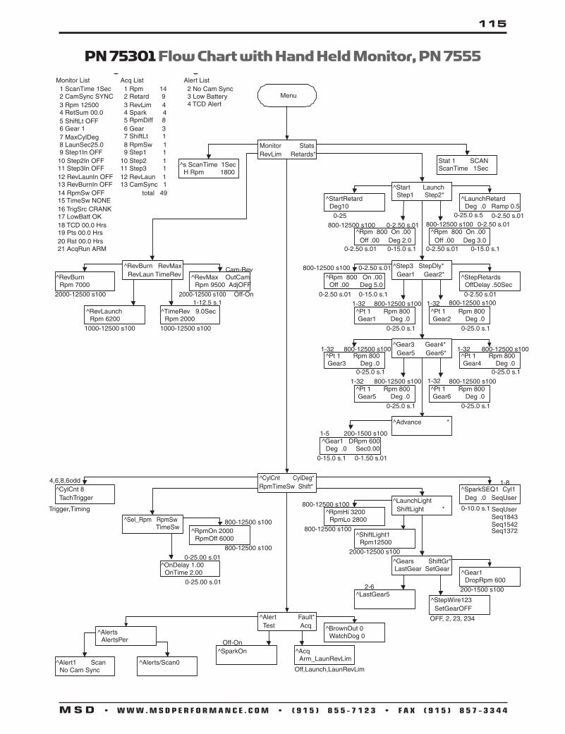
115
M S D • W W W . M S D P E R F O R M A N C E . C O M • ( 9 1 5 ) 8 5 5 - 7 1 2 3 • F A X ( 9 1 5 ) 8 5 7 - 3 3 4 4
75301 Programmable Digital-7 TAPN 75301 Flow Chart with Hand Held Monitor, PN 7555

116
M S D • W W W . M S D P E R F O R M A N C E . C O M • ( 9 1 5 ) 8 5 5 - 7 1 2 3 • F A X ( 9 1 5 ) 8 5 7 - 3 3 4 4
PN 7531 Flow Chart with Hand Held Monitor, PN 7555

117
M S D • W W W . M S D P E R F O R M A N C E . C O M • ( 9 1 5 ) 8 5 5 - 7 1 2 3 • F A X ( 9 1 5 ) 8 5 7 - 3 3 4 4
This section covers the race-only MSD 8 Ignition Controls. The MSD 8-Plus Ignition, PN 7805, supercedes the original MSD 8, PN 7800, and the Dual Coil MSD 8, PN 7802.
The MSD 8-Plus Ignition can be used on single or dual coil ignition systems. It is also compatible with 4, 6 or 8-cylinder engines. There is also a built-in 2-Step rev control to provide an overrev and launch rpm limit.
Operating Specifications Operating Voltage: +12-18 volts Current Requirements: 36 Amps @ 12,000 rpm RPM Range: 15,000 rpm with 14.4 volt supply Spark Duration: 20° Crankshaft Primary Voltage Output: 480 Volts Spark Energy: 315-345 milliJoules per spark Weight and Size: 4.85lbs., 8.25”L x 3.75”W x 5.75”H
Wire Functions
MSD 8-Series Ignition Controls
WARNING: When using a capacitive discharge ignition control, there is high voltage present at the coil primary terminals. Never touch the coil or connect test equipment to these terminals.
WARNING: During installation, disconnect the battery. When disconnecting the battery always remove the negative cable first and install it last.
Terminal Wire Function
ORANGE Connects to the positive (+) terminal of the second coil.This is the only wire that makes electrical contact with the coil positive terminal.
COIL 2 +
BLACK Connects to the negative (-) terminal of the second coil. This is the only wire that makes electrical contact with the coil negative terminal.
COIL 2-
HEAVYBLACK
This wire connects to a good ground, either at the battery negative (-) terminalor to the engine.
BAT -
HEAVYRED
GRAY
BAT +
TACHTACH
2-STEP
IGNITION Connects to a switched 12 volt source. Such as the ignition key or switch.RED
WHITE This wire is used to connect to the points, electronic ignition amplifier outputor to the Yellow wire of an MSD Timing Accessory. When this wire is used,the Magnetic Pickup connector is not used.
POINTS
VIOLETMAG +
GREENMAG -
DARKBLUE
This wire connects directly to the battery positive (+) terminal or to a positive battery junction or the positive side of the starter solenoid. Note: Never connect to the alternator.This terminal delivers a 12 volt square wave signal as an output for a tachometer or devices that require an rpm signal.
When this terminal is connected to 12 volts, RPM module 1 is active. When there is no 12 volts, RPM module 2 is active.
These wires are routed together in one harness from the Magnetic Pickup connector. The connector plugs directly into an MSD Distributor or Crank Trigger. It will also connect to factory magnetic pickups or other aftermarket pickups (Figure 4). The Violet wire is pos. (+) and the Green is neg. (-). When these wires are used, the Points Terminal is not.
ORANGECOIL 1 +
BLACKCOIL 1-
Connects to the positive (+) terminal of the coil.This is the only wire thatmakes electrical contact with the coil positive terminal. Connects to the negative (-) terminal of the coil. This is the only wire thatmakes electrical contact with the coil negative terminal.

118
M S D • W W W . M S D P E R F O R M A N C E . C O M • ( 9 1 5 ) 8 5 5 - 7 1 2 3 • F A X ( 9 1 5 ) 8 5 7 - 3 3 4 4
DISTRIBUTOR
TO 12 VOLTS
SUPPLIED JUMPER*
BLACK
TO SWITCHED12 VOLTS
TO CHASSIS
HEAVY BLACK TO BATTERY NEGATIVE
HEAVY RED TO BATTERY POSITIVE
BLUE
GRAYORANGE
Coil 1-
Coil 1+
Coil 2+
Coil 2-
*NOTE: WHEN USING A SINGLE COIL, BOTH COIL POSITIVE TERMINALS MUST BE CONNECTED TO THE COIL. EITHER CONNECT BOTH ORANGE WIRES TO THE COIL, OR USE THE SUPPLIED JUMPER TO CONNECT THE COIL POSITIVE TERMIANLS AT THE TERMINAL STRIP.
MSD 8-Plus Ignition to MSD Distributor/Crank Trigger
TO SWITCHED12 VOLTS
PN 8261
PN 8261
BLACK
ORANGE
BLACK
ORANGE
TO CHASSIS
HEAVY BLACK TOBATTERY NEGATIVE
HEAVY RED TOBATTERY POSITIVE
BLUE
GRAY
VIOLET
GREEN
Coil 1-
Coil 1+
Coil 2+
Coil 2-
MSD 8-Plus Ignition to Dual Coil System

119
M S D • W W W . M S D P E R F O R M A N C E . C O M • ( 9 1 5 ) 8 5 5 - 7 1 2 3 • F A X ( 9 1 5 ) 8 5 7 - 3 3 4 4
MSD 8-Plus Ignition to MSD Programmable Digital-7
Achieve the output power of the MSD 8-Plus with the advanced tuning of the Programmable Digital 7-Plus, PN 7531.
Gra
y
NO
TE:
Cha
nge
follo
win
g in
Pro
data
-Te
st S
park
ON
=
> Te
st S
park
OFF
Cyl
Cnt
Tac
h Tr
igge
r =
> Ta
ch T
imin
gR
evM
ax O
utCam
=>
Out
Rev
Gra
y
Plu
gs in
to n
umbe
r 2
mod
ule
only
LT B
LUE
GR
EEN
TO C
AM
SYN
CPIC
KU
P
GR
EEN
PN
88
60
HA
RN
ESS
HEAVY B
LACK
TO
BATT
ER
Y
3N
-PI
Pin
k-Ste
p1
Ret
ard/
Gea
r2
Vio
let
-Ste
p2
Ret
ard/
Gea
r3
Tan
-Ste
p3
Ret
ard/
Gea
r4
Red
-To
switch
ed1
2vo
lts
Whi
te-A
mpl
ifier
Trig
ger
Yello
w-Shi
ftLi
ght
Bro
wn/
Whi
te-R
PM
/Ti
me/
PSISw
itch
Dar
kB
lue
-
TOA
PM
SEN
SO
R
Bur
nout
Rev
Lim
it o
verr
ides
oth
er r
ev li
mits,
D
isab
les
Laun
ch H
isto
ry a
nd S
lew
Rev
Lim
it(W
ire
to o
utsi
de s
ourc
e to
be
switch
ed b
y cr
ew.)
Laun
ch R
ev L
imit t
o Li
ne L
ock
or C
lutc
h Sw
itch
Res
et for
Shi
ft L
ight
, G
ear
Indi
cato
r, L
aunc
h R
amp,
Gea
r Cur
ve, D
isab
les
Sle
w w
hen
Act
ivat
ed.
Ligh
t B
lue
-
VIO
LET
TD
AA
UP
TO
TU
TO S
WIT
CH
ED
12
VO
LTS
CBA
GR
EEN
VIO
LET
Coi
l 1-
Coi
l 1+
Coi
l 2+
Coi
l 2-

120
M S D • W W W . M S D P E R F O R M A N C E . C O M • ( 9 1 5 ) 8 5 5 - 7 1 2 3 • F A X ( 9 1 5 ) 8 5 7 - 3 3 4 4
MSD Dual Coil 8 Ignition, PN 7802, to Magnetic Pickup
MSD 8 Ignition, PN 7800, to Magnetic Pickup
NOTE: The MSD Dual Coil 8, PN 7802, has been obsoleted.
NOTE: Both of these ignitions have been superceded by the MSD 8 Plus, PN 7805.

121
M S D • W W W . M S D P E R F O R M A N C E . C O M • ( 9 1 5 ) 8 5 5 - 7 1 2 3 • F A X ( 9 1 5 ) 8 5 7 - 3 3 4 4
Installing MSD 10 Series Ignition Controls This section covers the wiring of the MSD 10 Ignition Series which have been obsoleted. It is recommended to use the MSD 8-Plus, PN 7805, Ignition Control in place.
There were two MSD 10 Ignitions; the original design with two coils, PN 7501, required a Pro Power CD Coil, PN 8201, and a Coupler Coil, PN 8209R. The revised model, PN 7502, required a special single coil, PN 8208
Wire Functions The MSD 10 features two terminal strips.
The heavy Red connects to the battery positive (+) terminal. The heavy Black con-nects the battery negative (-) terminal or other good engine ground. Connects to a switched 12 volts source.Connects to the positive side of the Pro Power Coupler Coil (PN 7501 only). Connects to the negative side of the Pro Power Coupler Coil (PN 7501 only).Connects to the negative (-) coil terminal. This is the only wire that makes electri-cal contact with the coil negative terminal.Connects to the positive (+) coil terminal. This is the only wire that makes electri-cal contact with the coil positive terminal.This is the trigger input terminal for points, amplifiers, a timing control or from an ECU. If this is connected, the magnetic pickup terminals will not be used. These are the magnetic pickup terminals that connect to an MSD Distributor or Crank Trigger. If these terminals are connected, the Points terminal will not be used. This is the tach output terminal. It provides a 12 volt square wave signal that most tachometers will accept. This is the 2-Step activation terminal. When this wire is grounded, Module 2 is activated. When not grounded, Module 1 is active.This can be used as an emergency kill switch. When grounded, the ignition system is turned Off.
Power Cables:
Ignition (Red):Power Coil + (Red):
Power Coil – (Blue):CD Coil - (Black):
CD Coil + (Orange):
Points (White):
Mag + (Violet):
Tach (Gray):
2-Step (Yellow):
Kill (Brown):
Mag – (Green)
Operating Specifications PN 7501 (Dual Coil) PN 7502 (Single Coil)
Operating Voltage: 12-18 volts Current Requirements: 17 Amps @ 8,000 rpm RPM Range: 13,000 rpm with 14.4 volt supply Spark Duration: CD Coil; 20° Crankshaft Inductive Coil; 20°-30° Crankshaft Primary Voltage Output: 520 Volts Spark Energy: CD Coil; 130 milliJoules per spark Inductive Coil; 500 milliJoules stored Weight and Size: 4.8lbs., 9”L x 4”W x 5.75”H
12-18 volts17 Amps @ 8,000 rpm13,000 rpm with 14.4 volt supplyCD Coil; 20° Crankshaft20°-30° Crankshaft630 Volts CD Coil; 700 milliJoules per spark
4.75 lbs., 8”L x 3.75”W x 5.75”H

122
M S D • W W W . M S D P E R F O R M A N C E . C O M • ( 9 1 5 ) 8 5 5 - 7 1 2 3 • F A X ( 9 1 5 ) 8 5 7 - 3 3 4 4
MSD 10 Ignition, PN 7501, to a Magnetic Pickup2-STEP
DISTRIBUTOR
MSD 10 Plus, PN 7502, to a Magnetic Pickup
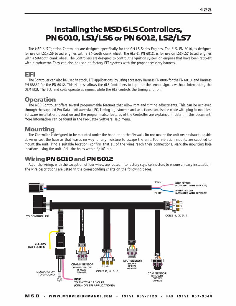
123
M S D • W W W . M S D P E R F O R M A N C E . C O M • ( 9 1 5 ) 8 5 5 - 7 1 2 3 • F A X ( 9 1 5 ) 8 5 7 - 3 3 4 4
BRN/WHTBROWNORANGEPINK
TO SWITCH 12 VOLTS(COIL+ ON EFI APPLICATIONS)
STEP RETARD(ACTIVATED WITH 12 VOLTS)
2-STEP REV LIMIT(ACTIVATED WITH 12 VOLTS)
BROWNGREEN
ORANGEORANGE/YELLOWBROWNORANGE
Installing the MSD 6LS Controllers, PN 6010, LS1/LS6 or PN 6012, LS2/LS7
The MSD 6LS Ignition Controllers are designed specifically for the GM LS-Series Engines. The 6LS, PN 6010, is designed for use on LS1/LS6 based engines with a 24-tooth crank wheel. The 6LS-2, PN 6012, is for use on LS2/LS7 based engines with a 58-tooth crank wheel. The Controllers are designed to control the ignition system on engines that have been retro-fit with a carburetor. They can also be used on factory EFI systems with the proper accessory harness.
EFI The Controller can also be used in stock, EFI applications, by using accessory Harness PN 8886 for the PN 6010, and Harness PN 88862 for the PN 6012. This Harness allows the 6LS Controllers to tap into the sensor signals without interrupting the OEM ECU. The ECU and coils operate as normal while the 6LS controls the timing and rpm.
Operation The MSD Controller offers several programmable features that allow rpm and timing adjustments. This can be achieved through the supplied Pro-Data+ software via a PC. Timing adjustments and selections can also be made with plug-in modules. Software installation, operation and the programmable features of the Controller are explained in detail in this document. More information can be found in the Pro-Data+ Software Help menu.
Mounting The Controller is designed to be mounted under the hood or on the firewall. Do not mount the unit near exhaust, upside down or seal the base as that leaves no way for any moisture to escape the unit. Four vibration mounts are supplied to mount the unit. Find a suitable location, confirm that all of the wires reach their connections. Mark the mounting hole locations using the unit. Drill the holes with a 3/16" bit.
Wiring PN 6010 and PN 6012 All of the wiring, with the exception of four wires, are routed into factory style connectors to ensure an easy installation. The wire descriptions are listed in the corresponding charts on the following pages.

124
M S D • W W W . M S D P E R F O R M A N C E . C O M • ( 9 1 5 ) 8 5 5 - 7 1 2 3 • F A X ( 9 1 5 ) 8 5 7 - 3 3 4 4
LOOSE WIRES
BLACK/GRAY Pin-A/B Ground. Connect to a ground source, such as the engine or battery negative.
PINK Pin-C On/Off wire. Connect to a switched 12 volt source. Coil and wire on EFI applications.
YELLOW Tach Signal. Provides a 12 volt square wave signal.
CRANKSHAFT SENSOR, 3-PIN
ORANGE/YELLOW Pin-A Crank Sensor Signal
BROWN Pin-B Sensor Ground
PINK Pin-C 12 Volt Supply
CAMSHAFT SENSOR, 3-PIN
BROWN/WHITE Pin-A Cam Sensor Signal
BROWN Pin-B Sensor Ground
PINK Pin-C 12 Volt Supply
MAP CONNECTOR, 3-PIN (OPTIONAL)
BROWN Pin-A Sensor Ground
LT. GREEN Pin-B MAP Sensor Signal
ORANGE Pin-C 5 Volt Supply
COIL CONNECTOR, CYLINDERS 2, 4, 6, 8
BLACK Pin-A Ground
RED/GREEN Pin-B Coil-2
BROWN/GREEN Pin-C Coil-4
BROWN Pin-E Sensor Ground
WHITE/BLUE Pin-F Coil-6
VIOLET/BLUE Pin-G Coil-8
PINK Pin-H 12 Volt Supply
Note: Pin-D is not used
COIL CONNECTOR, CYLINDERS 1, 3, 5, 7
BLACK Pin-A Ground
RED Pin-B Coil-7
GREEN Pin-C Coil-5
BROWN Pin-E Sensor Ground
LT. BLUE Pin-F Coil-3
VIOLET Pin-G Coil-1
PINK Pin-H 12 Volt Supply
Note: Pin-D is not used
Wire Functions, 6LS Controllers, PN 6010

125
M S D • W W W . M S D P E R F O R M A N C E . C O M • ( 9 1 5 ) 8 5 5 - 7 1 2 3 • F A X ( 9 1 5 ) 8 5 7 - 3 3 4 4
Wiring Functions, 6LS Controllers, PN 6010, continued 2-PIN CONNECTOR, ACCESSORIES
PINK Pin-A Step Retard. When 12 volts are supplied, the Sw Retard is activated.
BLUE Pin-B 2-Step. When 12 volts are supplied, the RevLO (Launch) rpm value is active.
16-PIN CONNECTOR WIRE LOCATION
GRAY Pin-A Ground
PINK Pin-B 12 Volt Supply
BROWN/WHITE Pin-C Cam Sensor Signal
RED/GREEN Pin-D Coil-2
BROWN/GREEN Pin-E Coil-4
WHITE/BLUE Pin-F Coil-6
VIOLET/BLUE Pin-G Coil-8
YELLOW Pin-H Tach
BROWN Pin-J Sensor Ground
LT. GREEN Pin-K MAP Sensor Signal
RED Pin-L Coil-7
GREEN Pin-M Coil-5
LT. BLUE Pin-N Coil-3
VIOLET Pin-P Coil-1
ORANGE/YELLOW Pin-R Crank Sensor Signal
ORANGE Pin-S 5 Volt Supply

126
M S D • W W W . M S D P E R F O R M A N C E . C O M • ( 9 1 5 ) 8 5 5 - 7 1 2 3 • F A X ( 9 1 5 ) 8 5 7 - 3 3 4 4
LOOSE WIRES
BLACK/GRAY Pin-A/B Ground. Connect to a ground source, such as the engine or battery negative.
PINK Pin-C On/Off wire. Connect to a switched 12 volt source. Coil and wire on EFI applications.
YELLOW Tach Signal. Provides a 12 volt square wave signal.
CRANKSHAFT SENSOR, 3-PIN
ORANGE/YELLOW Pin-A Crank Sensor Signal
BROWN Pin-B Sensor Ground
ORANGE Pin-C 5 Volt Supply
CAMSHAFT SENSOR, 3-PIN
BROWN/WHITE Pin-C Cam Sensor Signal
BROWN Pin-B Sensor Ground
ORANGE Pin-A 5 Volt Supply
MAP CONNECTOR, 3-PIN (OPTIONAL)
BROWN Pin-A Sensor Ground
LT. GREEN Pin-B MAP Sensor Signal
ORANGE Pin-C 5 Volt Supply
COIL CONNECTOR, CYLINDERS 2, 4, 6, 8
BLACK Pin-A Ground
RED/GREEN Pin-B Coil-2
BROWN/GREEN Pin-C Coil-4
BROWN Pin-E Sensor Ground
WHITE/BLUE Pin-F Coil-6
VIOLET/BLUE Pin-G Coil-8
PINK Pin-H 12 Volt Supply
Note: Pin-D is not used.
COIL CONNECTOR, CYLINDERS 1, 3, 5, 7
BLACK Pin-A Ground
RED Pin-B Coil-7
GREEN Pin-C Coil-5
BROWN Pin-E Sensor Ground
LT. BLUE Pin-F Coil-3
VIOLET Pin-G Coil-1
PINK Pin-H 12 Volt Supply
Note: Pin-D is not used.
Wire Functions 6LS-2, PN 6012

127
M S D • W W W . M S D P E R F O R M A N C E . C O M • ( 9 1 5 ) 8 5 5 - 7 1 2 3 • F A X ( 9 1 5 ) 8 5 7 - 3 3 4 4
2-PIN CONNECTOR, ACCESSORIES
PINK Pin-B Step Retard. When 12 volts are supplied, the Step Retard is activated.
BLUE Pin-A 2-Step. When 12 volts are supplied, the RevLaunch rpm value is active.
16-PIN CONNECTOR WIRE LOCATION
GRAY Pin-A Ground
PINK Pin-B 12 Volt Supply
BROWN/WHITE Pin-C Cam Sensor Signal
RED/GREEN Pin-D Coil-2
BROWN/GREEN Pin-E Coil-4
WHITE/BLUE Pin-F Coil-6
VIOLET/BLUE Pin-G Coil-8
YELLOW Pin-H Tach
BROWN Pin-J Sensor Ground
LT. GREEN Pin-K MAP Sensor Signal
RED Pin-L Coil-7
GREEN Pin-M Coil-5
LT. BLUE Pin-N Coil-3
VIOLET Pin-P Coil-1
ORANGE/YELLOW Pin-R Crank Sensor Signal
ORANGE Pin-S 5 Volt Supply
Wiring Functions 6LS-2, PN 6012, continued

128
M S D • W W W . M S D P E R F O R M A N C E . C O M • ( 9 1 5 ) 8 5 5 - 7 1 2 3 • F A X ( 9 1 5 ) 8 5 7 - 3 3 4 4
Programmable Features The following explains the programmable features of the PN 6010 Controller. The features are listed in the same order shown on the Data Editor list in the software. Note that the Help pull down menu of the software offers explanations of all the features.
RPM Table (RPMtbl) NOTE: When plotting a timing curve by using the RPM Table or MAP Table through your PC, there must NOT be a Timing
Module installed. Power-up with a module installed will override the saved timing plot.
This setting can only be modified from the RPM Timing Curve edit graph on the lower right of the screen. It can also be set with the Hand Held Monitor. The chart allows you to map out an entire timing curve, much like the centrifugal advance of a mechanical distributor. To create a map, simply position the mouse at a point on the chart and right click to add a dot. By moving the mouse over this point and a left click, the dot changes to red (active) and you can move it around the map.
NOTE: The timing has minimum and maximum limits that are set in the Data Editor Menu. These settings include the cumulative value of any vacuum advance or retard as well as the Switch Retard if used.
MAP Table (MAPtbl)NOTE: In order to take advantage of a vacuum advance or retard, a MAP sensor is required. NOTE: When plotting a timing curve by using the RPM Table or MAP Table through your PC, there must NOT be a Timing Module installed. Power-up with a module installed will override the saved timing plot.
This is a Manifold Absolute Pressure (MAP) chart. It gives you the capability of modifying the timing curve based on manifold pressure (vacuum or boost). A curve can be created from the MAP Advance Curve graph on the upper right of the screen. It can also be set with the Hand Held Monitor. The chart allows you to map out an advance curve based on manifold vacuum (much like the vacuum advance on a mechanical distributor). To create a map, simply position the mouse at a point on the chart and right click to add a dot. By moving the mouse over this point and a left click, the dot changes to red (active) and you can move it around the map.
NOTE: The timing has minimum and maximum limits that are set in the Data Editor Menu. These settings include the cumulative value of any vacuum advance or retard as well as the Switch Retard if activated.
MAP Sensor Select Allows the selection of a 1, 2 or 3-bar MAP sensor. This setting should be set to match the MAP Sensor in use: 1-bar (0-15 psia), 2-bar (0-30 psia), 3-bar (0-45 psia).
Timing Limit There are two adjustments that set the limits of ignition timing. These settings are meant as safety targets to keep the timing in check. Both the Minimum and Max values include any timing retards or advancements.
Min Timing: This is minimum amount of timing advance. It is adjustable from 0°-20° BTDC with a default of 5°. Max Timing: This is the maximum amount of timing advance. It is adjustable from 25°-65° BTDC with a default of 45°.

129
M S D • W W W . M S D P E R F O R M A N C E . C O M • ( 9 1 5 ) 8 5 5 - 7 1 2 3 • F A X ( 9 1 5 ) 8 5 7 - 3 3 4 4
Rev Limits The Controller allows you to program two rev limits; one for an over-rev safety and another that provides a low limit for use as a hole-shot, or 2-Step limit.
RevLO: This is the low rpm limit that is designed to be used while staged at the starting line. It is activated when the Blue wire is connected to 12 volts. When there is no 12 volts on this wire, the High Rev Limit is active. It is adjustable in 100 rpm increments from 2,000-12,500 rpm.
RevHI: This is the high, or over-rev rpm limit. It is active whenever the Blue wire (RevLO) is not connected to 12 volts. It is adjustable in 100 rpm increments from 2,000-12,500 rpm.
Step Retard (Sw Retard) A step retard will provide an adjustable amount of retard at a specific moment. This is ideal when using nitrous oxide. The amount of retard is adjustable from 0°-15° in 1° increments. The retard is activated when the Pink wire is switched to 12 volts. Default is 10°.
Idle Timing Control This is defaulted at Control DISABLE. When used on factory EFI systems, this should be switched to ENABLE. The controller will alter the ignition timing constantly to search for the best idle qualities.
NOTE: This is a function of an ECU controlled system and should be enabled when used with an OEM EFI application.
Timing Curve Modules The Controllers are supplied with six modules that plug into the side of the housing, shown in figure to right. The modules are labeled Curve 1, Curve 2, etc. By plugging in one of the modules, the timing curve will be set with a pre-programmed curve upon power-up of the Controller. (Removing the module while the engine is running will not affect the timing curve.) The figure below shows each of the timing curves.
NOTE: Any updates that are made using the PC software will be overridden if a module is left plugged in during power-up of the Controller.
Timing Curves from the Modules

130
M S D • W W W . M S D P E R F O R M A N C E . C O M • ( 9 1 5 ) 8 5 5 - 7 1 2 3 • F A X ( 9 1 5 ) 8 5 7 - 3 3 4 4
Pro-Data+ Installation of the Pro-Data+ Software1. Insert the installation CD into your PC. 2. In Windows, click on Start then select Run. 3. In the box type, “D: Setup” and press Enter (or corresponding drive). 4. The screen will walk you through several steps. 5. Once loaded, your monitor will have an MSD Graph View logo. Click on it to open the software. 6. A program will open. Go to the upper left corner of the screen and click on File, then Open. 7. This will open a menu of part numbers. Select “6010” or “6012”. 8. This will open another menu of versions. Highlight and open the “6010vxx.IGN” or “6012vxx.IGN” (xx determines the
versions, such as 02). This will open the Pro-Data+ Software for the Ignition Controller.
Saves and TransfersWhenever a change is made to a program, it either must be saved to a file in your PC or it needs to be transferred to the Controller. You will notice that whenever you make a change to a program, the bullet next to the modified value will turn red. It will remain red until you save it to a file or to the MSD. There are two ways to save your files.
Save to MSD: This step will save any changes directly into the Controller. If you are only making one or just a couple modifications this works well.
Save to PC: This will save your changes to only show on the PC screen (indicated by a red bullet point next to any altered values). These modifications will not be active or saved until you save the file or transfer the information to the MSD.
You can create numerous files on your PC and download them for testing purposes or save programs you used at different races or events.
Pro-Data+ Screen and Programming Windows
Real TimeMonitor
MAP Advance Chart
Timing MapMenuTree
Gauges
Notes

131
M S D • W W W . M S D P E R F O R M A N C E . C O M • ( 9 1 5 ) 8 5 5 - 7 1 2 3 • F A X ( 9 1 5 ) 8 5 7 - 3 3 4 4
Installing the 6-MOD Controller, PN 6011
The MSD 6-MOD Controller is designed specifically for the Ford Modular Engine series equipped with coil-on-plug ignition systems. The 6-MOD is designed to drive the factory coils and control the ignition system on engines that have been retro-fit with a carburetor. They can also be used on factory EFI systems with the proper accessory harness.
EFIThe 6-MOD can be used in stock, EFI applications by using accessory Harness, PN 88814. This harness provides a splice-free installation of the Controller to factory equipped EFI vehicles making installation easy. This allows the user to advance or retard the factory’s timing curve, program their own, set a step retard, boost retard, step rev limits and more.
OperationThe 6-MOD Controller offers several programmable feature that allow rpm and timing adjustments. These can be achieved through MSD’s Pro-Data+ Software via a PC (free download at www.msdignition.com). Loading the software is explained in this section and there is a useful Help menu found in the software for more details.
NOTE: The harness is set up for use on a SOHC engine. DOHC engines use coils with reversed polarity. In these applications, the location of two coil wires needs to be swapped in each connector.
COIL 4
COIL 3
COIL 2
COIL 1
COIL 8
COIL 7
COIL 6
COIL 5
12V - REDCOIL INPUT - BROWN/YELLOW
GROUND
CAMBROWN - TAN
MAP
OEM COIL1CONNECTOR
FOR CARBURETOR APPLICATIONS,CUT WIRES. CONNECT RED TO ASWITCHED 12 VOLT SOURCE.BROWN/YELLOW IS NOT USED.
FOR EFI APPLICATIONSHARNESS PN 88814 IS REQUIRED
TOCONTROLLER
B-RED A-BLACK
A-RED
B-PURPLE/BLUE
A-RED
B-PINK
A-RED
B-WHITE/BLUE
A-RED
B-GREEN
B-BROWN/GREEN
A-RED
B-LT. BLUE
A-RED
B-RED/GREEN
A-RED
B-VIOLET
A-RED, COMMON 12V
BLUE/2-STEPPINK/RETARD
YELLOW-TACH
GREEN
ORANGE
BROWN
BROWN/YELLOW
RED

132
M S D • W W W . M S D P E R F O R M A N C E . C O M • ( 9 1 5 ) 8 5 5 - 7 1 2 3 • F A X ( 9 1 5 ) 8 5 7 - 3 3 4 4
POWER WIRES
RED 12 volt input. Connect to switched 12 volts.
BROWN/YELLOW Use only with EFI. Coil input wire.
BLACK Ground. Connect eyelet to ground.
LOOSE WIRES
YELLOW Tach Signal. Provides a 12 volt square wave source.
PINK Step Retard. When 12 volts are applied, the step retard is activated.
BLUE 2-Step. When 12 volts are applied, the RevLaunch rpm value is active.
MAP SENSOR
BROWN Pin-A Ground
GREEN Pin-B Map Signal
ORANGE Pin-C 5 volt supply
CRANKSHAFT SENSOR
BLACK Pin-A Signal Negative (-)
RED Pin-B Signal Positive (+)
CAMSHAFT SENSOR
BROWN Pin-A Ground
TAN Pin-B Signal Wire
COIL CONNECTORS
RED Pin-A* 12 volt supply
VIOLET Pin-B* Coil-1 Trigger
RED/GREEN Pin-B* Coil-2 Trigger
LT. BLUE Pin-B* Coil-3 Trigger
BROWN/GREEN Pin-B* Coil-4 Trigger
GREEN Pin-B* Coil-5 Trigger
WHITE/BLUE Pin-B* Coil-6 Trigger
PINK Pin-B* Coil-7 Trigger
VIOLET/BLUE Pin-B* Coil-8 Trigger
Note: For carburetor applications only this connector is cut off and the Brown/Yellow is not used. For EFI applications, this connects to the number one coil connector using harness, PN 88814.
*Note: The harness is set up for use on a SOHC engine. DOHC engines use coils with reversed polarity. In these applications, the location of two coil wires needs to be swapped in each connector.
Wire Functions, 6-MOD Controller, PN 6011

133
M S D • W W W . M S D P E R F O R M A N C E . C O M • ( 9 1 5 ) 8 5 5 - 7 1 2 3 • F A X ( 9 1 5 ) 8 5 7 - 3 3 4 4
Programmable Features The following explains the programmable features of the PN 6011 Controller. The features are listed in the same order shown on the Data Editor list in the software. Note that the Help pull down menu of the software offers explanations of all the features.
RPM Table (RPMtbl) This setting can only be modified from the RPM Timing Curve edit graph on the lower right of the screen (It can also be set with the Hand Held Monitor). The chart allows you to map out an entire timing curve, much like the centrifugal advance of a mechanical distributor. To create a map, simply position the mouse at a point on the chart and right click to add a dot. Up to 10 points can be added. By moving the mouse over this point and a left click, the dot changes to red (active) and you can move it around the map by clicking and dragging.
NOTE: The timing has minimum and maximum limits that are set in the Data Editor Menu. These settings include the cumulative value of any vacuum advance or retard as well as the Switch Retard if used.
MAP Table (MAPtbl)NOTE: In order to take advantage of a vacuum advance, a MAP sensor is required.
This is a Manifold Absolute Pressure (MAP) chart. It gives you the capability of modifying the timing curve based on manifold pressure (vacuum or boost). A curve can be created from the MAP Advance Curve graph on the upper right of the screen (It can also be set with the Hand Held Monitor). The chart allows you to map out an advance curve based on manifold vacuum (much like the vacuum advance on a mechanical distributor). To create a map, simply position the mouse at a point on the chart and right click to add a dot. Up to 10 points can be added. By moving the mouse over this point and a left click, the dot changes to red (active) and you can move it around the map by clicking and dragging.
NOTE: The timing has minimum and maximum limits that are set in the Data Editor Menu. These settings include the cumulative value of any vacuum advance or retard as well as the Step Retard if activated.
MAP Sensor Select Allows the selection of a 1, 2 or 3-bar MAP sensor. This setting should be set to match the MAP Sensor in use: 1-bar (0-15 psia), 2-bar (0-30 psia), 3-bar (0-45 psia). A 2-bar Sensor is supplied.
Timing Limit There are two adjustments that set the limits of ignition timing. These settings are meant as safety targets to keep the timing in check. Both the Minimum and Max values include any timing retards or advancements.
Min Timing: This is the minimum amount of timing advance. It is adjustable from 0°-20° BTDC with a default of 5°.
Max Timing: This is the maximum amount of timing advance. It is adjustable from 25°-65° BTDC with a default of 45°.

134
M S D • W W W . M S D P E R F O R M A N C E . C O M • ( 9 1 5 ) 8 5 5 - 7 1 2 3 • F A X ( 9 1 5 ) 8 5 7 - 3 3 4 4
Rev Limits The Controller allows you to program two rev limits; one for an over-rev safety and another that provides a low limit for use as a launch, or 2-Step limit.
RevLaunch This is the low rpm limit that is designed to be used while staged at the starting line. It is activated when the Blue wire is connected to 12 volts. When there is no 12 volts on this wire, the High Rev Limit is active. It is adjustable in 100 rpm increments from 2,000-12,500 rpm.
RevMax This is the high, or over-rev rpm limit. It is active whenever the Blue wire (RevLO) is not connected to 12 volts. It is adjustable in 100 rpm increments from 2,000-12,500 rpm.
Step Retard A step retard will provide an adjustable amount of retard at a specific moment. This is ideal when using nitrous oxide. The amount of retard is adjustable from 0°-15° in 1° increments. The retard is activated when the Pink wire is switched to 12 volts. Default is 10°.
Timing Source This adjustment allows you to select a timing curve. The 6-Mod lets you run a Built-In default curve that can easily be modified by using the RPM Table chart. On engines using the factory EFI you can select OEM Advance or OEM Retard to use the factory ECU’s timing map.
Built-In: This is a general timing curve that is designed to work well with most stock type engines. This chart is shown in the RPM Table and MAP Table charts. These can easily be modified by clicking and dragging on the dots, or by adding a dot (right click) and saving to the ignition.
OEM Advance: This selection is used with a factory EFI equipped engine. The 6-Mod will use the factory ECU’s timing curve. By using the OEM Timing Mod option below, the entire timing curve will be advanced the amount you set.
OEM Retard: This selection is used with a factory EFI equipped engine. The 6-Mod will use the factory ECU’s timing curve. By using the OEM Timing Mod option below, the entire timing curve will be retarded the amount you set.
OEM Timing Mod This option is available only when running the factory ECU’s timing curve on EFI equipped engines (Selected as OEM Advance or Retard). Here you set the total amount of advance or retard for the factory timing curve. The default is 0°.
OEMtimingmod: Adjustable from 0° - 10°.

135
M S D • W W W . M S D P E R F O R M A N C E . C O M • ( 9 1 5 ) 8 5 5 - 7 1 2 3 • F A X ( 9 1 5 ) 8 5 7 - 3 3 4 4
Pro-Data+ Installation of the Pro-Data+ Software1. Insert the installation CD into your PC. 2. In Windows, click on Start then select Run. 3. In the box type, “D: Setup” and press Enter (or corresponding drive). 4. The screen will walk you through several steps. 5. Once loaded, your monitor will have an MSD Graph View logo. Click on it to open the software. 6. A program will open. Go to the upper left corner of the screen and click on File, then Open. 7. This will open a menu of part numbers. Select “6011”. 8. This will open another menu of versions. Highlight and open the “6011vxx.IGN” (xx determines the versions, such as 02).
This will open the Pro-Data+ software for the Ignition Controller.
Saves and Transfers Whenever a change is made to a program, it either must be saved to a file in your PC or it needs to be transferred to the Controller. You will notice that whenever you make a change to a program, the bullet next to the modified value will turn red. It will remain red until you save it to a file or to the MSD. There are two ways to save your files.
Save to MSD: This step will save any changes directly into the Controller. If you are only making one or just a couple modifications this works well.
Save to PC: This will save your changes to only show on the PC screen (indicated by a red bullet point next to any altered values). These modifications will not be active or saved until you save the file or transfer the information to the MSD.
You can create numerous files on your PC and download them for testing purposes or save programs you used at different races or events.
Pro-Data+ Screen and Programming Windows
Real TimeMonitor
MAP Advance Chart
Timing MapMenuTree
Gauges
Notes

136
M S D • W W W . M S D P E R F O R M A N C E . C O M • ( 9 1 5 ) 8 5 5 - 7 1 2 3 • F A X ( 9 1 5 ) 8 5 7 - 3 3 4 4
Installing the 6-Hemi® Controller, PN 6013
Hemi® is a Registered trademark of Chrysler LLC .
Wiring with the '03-'05 PN 88863 Harness for Carburetors
COIL CONNECTORON ’03-’05V8 MODELS
2 PIN
COIL 1COIL 3COIL 5COIL 7
COIL 2COIL 4COIL 6COIL 8
MAP
CRANK
VIOLETREDLT. BLUEREDGREENREDPINKRED
VIO/BLU RED RED
WHT/BLU
BRN/GRN RED
BLK/GRN RED
LT GREENBROWNORANGE
ORANGEBROWNBRN/WHT CAM
ORANGEBROWNORG/YEL
(OPTIONAL)
TOTACH
YELLOW
PINK STEP RETARDBLUE LAUNCH
BRN/YELNOT USED
GROUND BLK W/GRAY
TO SWITCHED12 VOLTS
7 5 13
8 6 2FRONT
4
EFI APPLICATIONS ONLY
RED/GREEN
NOTE: For EFI applications only. Use PN 88815. Cut only with carburetors.
The MSD 6-HEMI Controller is designed specifically for the Chrysler HEMI Engine series equipped with coil-on-plug ignition systems. The 6-HEMI is designed to drive the factory coils and control the ignition system on engines that have been retro-fit with a carburetor. Due the two different coil offerings, a coil harness must be purchased separately. PN 88863 is designed for the ’03-’05 coil design (which use spark plug wires) and the PN 88864 for ’06-’08 model coils.
EFIThe 6-HEMI can be used in stock, EFI applications by using the corresponding accessory harness. Two Adapter Har-nesses are available; PN 88815 for ’03-’05 coils and the PN 88816 for the ’06-’08 coil models. These harnesses provides a splice-free installation of the Controller to factory equipped EFI vehicles making installation easy. This allows the user to advance or retard the factory’s timing curve, program their own, set a step retard, boost retard, step rev limits and more.
OperationThe 6-HEMI Controller offers several programmable feature that allow rpm and timing adjustments. These can be achieved through MSD’s Pro-Data+ Software via a PC (free download at www.msdignition.com). Loading the software is explained in this section and there is a useful Help menu found in the software for more details.

137
M S D • W W W . M S D P E R F O R M A N C E . C O M • ( 9 1 5 ) 8 5 5 - 7 1 2 3 • F A X ( 9 1 5 ) 8 5 7 - 3 3 4 4
Installing an MSD 6-Hemi® Controller, PN 6013
POWER WIRES
RED/GREEN 12 volt input. Connect to switched 12 volts.
BROWN/YELLOW Use only with EFI. Coil-1 input wire (See note on EFI diagram).
BLACK/GRAY Ground. Connect eyelet to ground.
LOOSE WIRES
YELLOW Tach Signal. Provides a 12 volt square wave source.
PINK Step Retard. When 12 volts are applied, the step retard is activated.
BLUE 2-Step. When 12 volts are applied, the RevLaunch rpm value is active.
BROWN '06-'07 Harness, PN 88864 only: Waste Spark Control. To disable waste spark, cut
the wire loop.
MAP SENSOR
LIGHT GREEN Pin-1 Map Signal
BROWN Pin-2 Ground
ORANGE Pin-3 5 volt supply
CRANKSHAFT SENSOR
ORANGE Pin-1 5 volt supply
BROWN Pin-2 Ground
ORANGE/YELLOW Pin-3 Crank Signal
CAMSHAFT SENSOR
BROWN/WHITE Pin-1 Cam Signal
BROWN Pin-2 Ground
ORANGE Pin-3 5 volt supply
COIL CONNECTORS
Note: PN 88864, '06-'07 applications with 3-pin coil connector. Pin-1 is signal and Pin-2 is 12 volt supply.
RED Pin-1 12 volt supply (for all cylinders)
VIOLET Pin-2 Coil-1 Trigger
BLACK/GREEN Pin-2 Coil-2 Trigger
LIGHT BLUE Pin-2 Coil-3 Trigger
BROWN/GREEN Pin-2 Coil-4 Trigger
GREEN Pin-2 Coil-5 Trigger
WHITE/BLUE Pin-2 Coil-6 Trigger
PINK Pin-2 Coil-7 Trigger
VIOLET/BLUE Pin-2 Coil-8 Trigger
Note: For carburetor applications this connector is cut off and the Brown/Yellow is not used. For EFI applications, this connector connects to the Coil-1 connector (See note on diagrams on following pages).
Wire Functions

138
M S D • W W W . M S D P E R F O R M A N C E . C O M • ( 9 1 5 ) 8 5 5 - 7 1 2 3 • F A X ( 9 1 5 ) 8 5 7 - 3 3 4 4
RED
COIL CONNECTORON LATE ’06-’07V8 MODELS
3 PIN
COIL 1COIL 3COIL 5COIL 7
COIL 2COIL 4COIL 6COIL 8
CRANK
VIOLETREDLT. BLUEREDGREENREDPINKRED
VIO/BLU RED
WHT/BLU
BRN/GRN RED
BLK/GRN RED
LT GREENBROWNORANGE
ORANGEBROWN
BRN/WHT
ORANGEBROWNORG/YEL
YELLOW
(OPTIONAL)
TOTACH
BROWNJUMPER
PINK STEP RETARDBLUE LAUNCH
EFI APPLICATIONS ONLY
7 5 13
8 6 2FRONT
4
BRN/YELNOT USED
GROUND BLK W/GRAY
TO SWITCHED12 VOLTS
RED/GREEN
MAP
CAM
Wiring with the '06-'07, PN 88864 Harness for CarburetorsNOTE: For EFI applications only. Use PN 88816. Cut only with carburetors.
TO OEM COIL 1CONNECTOR
TACH ADAPTER
PN 88816 - ’06-’07
12V - RED/GRNCOIL INPUT - BRN/YEL
USE O
NCO
IL 1
RED
COIL CONNECTORON LATE ’06-’07V8 MODELS
3 PIN
COIL 1COIL 3COIL 5COIL 7
COIL 2COIL 4COIL 6COIL 8
CRANK
VIOLETREDLT. BLUEREDGREENREDPINKRED
VIO/BLU RED
WHT/BLU
BRN/GRN RED
BLK/GRN RED
LT GREENBROWNORANGE
ORANGEBROWN
BRN/WHT
ORANGEBROWNORG/YEL
YELLOW
(OPTIONAL)
TOTACH
BROWNJUMPER
PINK STEP RETARDBLUE LAUNCH
7 5 13
8 6 2FRONT
4
GROUND BLK W/GRAY
MAP
CAM
Wiring to Factory EFI on a ’06-’08 with Harnesses PN 88864 and PN 88816

139
M S D • W W W . M S D P E R F O R M A N C E . C O M • ( 9 1 5 ) 8 5 5 - 7 1 2 3 • F A X ( 9 1 5 ) 8 5 7 - 3 3 4 4
Programmable Features The following explains the programmable features of the PN 6013 Controller. The features are listed in the same order shown on the Data Editor list in the software. Note that the Help pull down menu of the software offers explanations of all the features.
NOTE: STATS, Stat 1 or SCAN are display features only used with the Hand Held Monitors, PN 7550 or PN 7553.
RPM Table (RPMtbl) This setting can only be modified from the RPM Timing Curve edit graph on the lower right of the screen (It can also be set with the Hand Held Monitor). The chart allows you to map out an entire timing curve, much like the centrifugal advance of a mechanical distributor. To create a map, simply position the mouse at a point on the chart and right click to add a dot. Up to 10 points can be programmed. By moving the mouse over this point and a left click, the dot changes to red (active) and you can move it around the map by clicking and dragging.
NOTE: The timing has minimum and maximum limits that are set in the Data Editor Menu. These settings include the cumulative value of any vacuum advance or retard as well as the Step Retard if activated.
MAP Table (MAPtbl)NOTE: In order to take advantage of a vacuum advance, a MAP sensor is required.
This is a Manifold Absolute Pressure (MAP) chart. It gives you the capability of modifying the timing curve based on manifold pressure (vacuum or boost). A curve can be created from the MAP Advance Curve graph on the upper right of the screen (It can also be set with the Hand Held Monitor). The chart allows you to map out an advance curve based on manifold vacuum (much like the vacuum advance on a mechanical distributor). To create a map, simply position the mouse at a point on the chart and right click to add a dot. Up to 10 points can be programmed. By moving the mouse over this point and a left click, the dot changes to red (active) and you can move it around the map by clicking and dragging.
NOTE: The timing has minimum and maximum limits that are set in the Data Editor Menu. These settings include the cumulative value of any vacuum advance or retard as well as the Step Retard if activated.
MAP Sensor Select Allows the selection of a 1, 2 or 3-bar MAP sensor. This setting should be set to match the MAP Sensor in use: 1-bar (15 psia), 2-bar (30 psia), 3-bar (45 psia). (Uses a Factory Mopar map sensor.)
Timing Limit There are two adjustments that set the limits of ignition timing. These settings are meant as safety targets to keep the timing in check. Both the Minimum and Max values include any timing retards or advancements.
Min Timing: The minimum timing setting. It is adjustable from -5°-20° BTDC with a default of 5°. Max Timing: The maximum timing setting. It is adjustable from 25°-65° BTDC with a default of 45°.
NOTE: These features are active when operating in OEM Advance or Built-In timing mode.
Rev Limits The Controller allows you to program two rev limits; RevMax for an over-rev safety and RevLaunch that provides a low limit for use as a launch, or 2-Step limit.
RevLaunch: This is the low rpm limit that is designed to be used while staged at the starting line. It is activated when the Blue wire is connected to 12 volts. When there is no 12 volts on this wire, the RevMax Limit is active. It is adjustable in 100 rpm increments from 2,000-12,500 rpm.
RevMax: This is the over-rev rpm limit. It is active when the Blue wire (RevLaunch) is not connected to 12 volts. It is adjustable in 100 rpm increments from 2,000-12,500 rpm.

140
M S D • W W W . M S D P E R F O R M A N C E . C O M • ( 9 1 5 ) 8 5 5 - 7 1 2 3 • F A X ( 9 1 5 ) 8 5 7 - 3 3 4 4
Step Retard A step retard will provide an adjustable amount of retard at a specific moment. This is ideal when using nitrous oxide. The amount of retard is adjustable from 0°-15° in 1° increments. The retard is activated when the Pink wire is switched to 12 volts. Default is 10°.
Timing Source This adjustment allows you to select a timing curve. The 6-Hemi lets you run a Built-In default curve that can easily be modified by using the RPM Table chart. On engines using the factory EFI, you can select OEM Advance to use the factory ECU’s timing map.
Built-In: This is a general timing curve that is designed to work well with most stock type engines. This chart is shown in the RPM Table and MAP Table charts. These can easily be modified by clicking and dragging on the dots, or by adding a dot (right click) and saving to the ignition (The built in timing curve is designed for 91+ octane fuel).
OEM Advance: This selection is used with a factory EFI equipped engine. The 6-Hemi will use the factory ECU’s timing curve. By using the OEM Timing Mode option below, the entire timing curve will be advanced the amount you set. A negative value retards the timing.
OEM Timing Mode This option is available only when running the factory ECU’s timing curve on EFI equipped engines (Selected as OEM Advance or Retard). Here you set the total amount of advance or retard for the factory timing curve (Negative value will retard the timing). The default is 0°.
OEMtimingMod: Adjustable from retard 10° to advance 10°.
Caution: Too much advance can cause damage to engine!
Idle Timing Control When this feature is On, the timing will fluctuate during idle to improve the idle quality. This is only used during the "Built-In" timing mode.
On: Idle timing will vary to produce a more stable idle RPM.Off: Timing will be fixed, based on the timing tables.
Waste Spark Option When this feature is On, each coil will fire every 360°. When turned Off, each coil will fire every 720° of crankshaft rotation.
Harness: When harness PN 88864 is used, waste spark is Off. When harness PN 88863 is used, waste spark is On.On: Coil firing order = 1 and 6, 8 and 5, 4 and 7, 3 and 2.Off: Coil firing order = 1, 8, 4, 3, 6, 5, 7, 2.
FRONT VIEW OF ENGINE
CAM SENSOR
SIDE VIEW OF ENGINE
REAR FRONT
CRANK SENSOR
MAP SENSOR (BEHIND ALTERNATOR OR ATTHE REAR OF THEINTAKE MANIFOLD)
Cam, Crank and Map Sensor locations

141
M S D • W W W . M S D P E R F O R M A N C E . C O M • ( 9 1 5 ) 8 5 5 - 7 1 2 3 • F A X ( 9 1 5 ) 8 5 7 - 3 3 4 4
Pro-Data+ Installation of the Pro-Data+ Software1. Insert the installation CD into your PC or download from www.msdignition.com. 2. In Windows, click on Start then select Run. 3. In the box type, “D: Setup” and press Enter (or corresponding drive). 4. The screen will walk you through several steps. 5. Once loaded, your monitor will have an MSD Graph View logo. Click on it to open the software. 6. A program will open. Go to the upper left corner of the screen and click on File, then Open. 7. This will open a menu of part numbers. Select “6013”. 8. This will open another menu of versions. Highlight and open the “6013vxx.IGN” (xx determines the versions, such as 02).
This will open the Pro-Data+ software for the Ignition Controller.
Saves and Transfers Whenever a change is made to a program, it either must be saved to a file in your PC or it needs to be transferred to the Controller. You will notice that whenever you make a change to a program, the bullet next to the modified value will turn red. It will remain red until you save it to a file or to the MSD. There are two ways to save your files.
Save to MSD: This step will save any changes directly into the Controller. If you are only making one or just a couple modifications this works well.
Save to PC: This will save your changes to only show on the PC screen (indicated by a red bullet point next to any altered values). These modifications will not be active or saved until you save the file or transfer the information to the MSD.
You can create numerous files on your PC and download them for testing purposes or save programs you used at different races or events.
Pro-Data+ Screen and Programming Windows
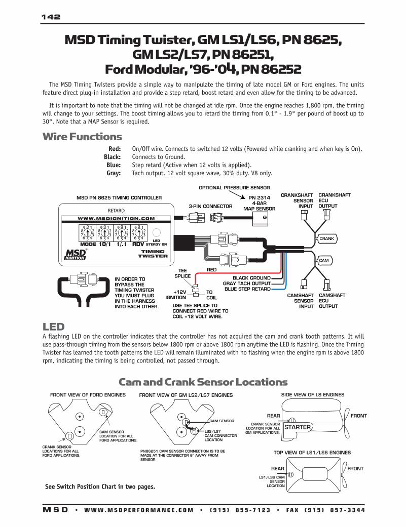
142
M S D • W W W . M S D P E R F O R M A N C E . C O M • ( 9 1 5 ) 8 5 5 - 7 1 2 3 • F A X ( 9 1 5 ) 8 5 7 - 3 3 4 4
RETARD
0
5
123
4
987
6
0
5
123
4
987
6
0
5
123
4
987
6
0
5
123
4
987
6
MSD PN 8625 TIMING CONTROLLER
OPTIONAL PRESSURE SENSOR
3-PIN CONNECTOR
PN 23144-BAR
MAP SENSOR
CAMSHAFTSENSOR
INPUT
CAMSHAFTECUOUTPUT
CRANKSHAFTSENSOR
INPUT
CRANKSHAFTECUOUTPUT
BLACK GROUNDGRAY TACH OUTPUTBLUE STEP RETARD
IN ORDER TO BYPASS THE TIMING TWISTER YOU MUST PLUG IN THE HARNESS INTO EACH OTHER.
CRANK
CAM
+12VIGNITION
TOCOIL
TEESPLICE
RED
USE TEE SPLICE TO CONNECT RED WIRE TO COIL +12 VOLT WIRE.
Wire F unctions Red: On/Off wire. Connects to switched 12 volts (Powered while cranking and when key is On). Black: Connects to Ground. Blue: Step retard (Active when 12 volts is applied). Gray: Tach output. 12 volt square wave, 30% duty. V8 only.
MSD Timing Twister, GM LS1/LS6, PN 8625,GM LS2/LS7, PN 86251,
Ford Modular, ’96-’04, PN 86252
LEDA flashing LED on the controller indicates that the controller has not acquired the cam and crank tooth patterns. It will use pass-through timing from the sensors below 1800 rpm or above 1800 rpm anytime the LED is flashing. Once the Timing Twister has learned the tooth patterns the LED will remain illuminated with no flashing when the engine rpm is above 1800 rpm, indicating the timing is being controlled, not passed through.
The MSD Timing Twisters provide a simple way to manipulate the timing of late model GM or Ford engines. The units feature direct plug-in installation and provide a step retard, boost retard and even allow for the timing to be advanced.
It is important to note that the timing will not be changed at idle rpm. Once the engine reaches 1,800 rpm, the timing will change to your settings. The boost timing allows you to retard the timing from 0.1° - 1.9° per pound of boost up to 30°. Note that a MAP Sensor is required.
Cam and Crank Sensor LocationsSIDE VIEW OF LS ENGINES
REAR FRONT
CRANK SENSOR LOCATION FOR ALL GM APPLICATIONS.
STARTER
TOP VIEW OF LS1/LS6 ENGINES
REAR FRONT
LS1/LS6 CAM SENSOR
LOCATION
FRONT VIEW OF GM LS2/LS7 ENGINES
CAM SENSOR
LS2/LS7CAM CONNECTORLOCATION
PN86251 CAM SENSOR CONNECTION IS TO BE MADE AT THE CONNECTOR 6” AWAY FROM SENSOR.
FRONT VIEW OF FORD ENGINES
CRANK SENSOR LOCATIONS FOR ALL FORD APPLICATIONS.
CAM SENSOR LOCATION FOR ALL FORD APPLICATIONS.
See Switch Position Chart in two pages .

143
M S D • W W W . M S D P E R F O R M A N C E . C O M • ( 9 1 5 ) 8 5 5 - 7 1 2 3 • F A X ( 9 1 5 ) 8 5 7 - 3 3 4 4
Wire F unctions Red: On/Off wire. Connects to switched 12 volts (Powered while cranking and when key
is On). NOTE: Do not connect Red wire to coil positive. Black: Connects to Ground. Blue: Step retard (Active when 12 volts is applied). Gray: Tach output. 12 volt square wave, 30% duty. V8 only (4 pulses per rev).
MSD PN 8684 TIMING RETARD CONTROLOPTIONAL PRESSURE SENSORPN 2314
3-PIN CONNECTOR4-BAR
MAP SENSOR
CAMSHAFTSENSOR
INPUT
CAMSHAFTECUOUTPUT
CRANKSHAFTSENSOR
INPUT
CRANKSHAFTECUOUTPUT
IN ORDER TO BYPASS THE TIMING RETARD CONTROLYOU MUST PLUG IN THE HARNESS INTO EACH OTHER.
BLACK GROUNDGRAY TACH OUTPUTBLUE STEP RETARD
+12VIGNITION
TOECU
TEESPLICE
RED
USE TEE SPLICE TO CONNECT TO ECU+12 VOLT WIRE.
0
5
123
4
987
6
0
5
123
4
987
6
0
5
123
4
987
6
0
5
123
4
987
6
Timing Retard Control Cam and Crank Sensor LocationsFRONT VIEW OF ENGINE
CAM SENSOR LOCATION FOR ALL HEMI APPLICATIONS.
SIDE VIEW OF ENGINE
REAR FRONT
CRANK SENSOR LOCATIONFOR ALL HEMI APPLICATIONS.
MSD Timing Retard for Late Model HEMI®, PN 8684
This Timing Retard is designed specifically for the ’03 and On Chrysler HEMI. It provides a simple way to retard the timing. The units feature direct plug-in installation and provide a step retard and boost retard (MAP Sensor required).
It is important to note that the timing will not be changed at idle rpm. Once the engine reaches 1,800 rpm, the timing will change to your settings. The boost timing allows you to retard the timing from 0.1° - 1.9° per pound of boost up to 30°.
Hemi® is a Registered trademark of Chrysler LLC .
LEDA flashing LED on the controller indicates that the controller has not acquired the cam and crank tooth patterns. It will use pass-through timing from the sensors below 1800 rpm or above 1800 rpm anytime the LED is flashing. Once the Timing Twister has learned the tooth patterns the LED will remain illuminated with no flashing when the engine rpm is above 1800 rpm, indicating the timing is being controlled, not passed through.

144
M S D • W W W . M S D P E R F O R M A N C E . C O M • ( 9 1 5 ) 8 5 5 - 7 1 2 3 • F A X ( 9 1 5 ) 8 5 7 - 3 3 4 4
ADV*Switch Position
10° RetardSwitch Position
0=0°1=10°2=20°
1° RetardSwitch Position
3 thru 9=30°
0=0°1 thru 9=1°
0=0°1 thru 9=1°
0=0°1 thru 9=1 °
Step Retard0=0°1=2°2=4°3=6°4=8°
5=10°6=12°7=14°8=16°9=18°
Step Retard0=0°1=2°2=4°3=6°4=8°
5=10°6=12°7=14°8=16°9=18°
Step Retard0=0°1=2°2=4°3=6°4=8°
5=10°6=12°7=14°8=16°9=18°
0=0°1=1°2=2°
3=3°4=4°5=5°
6=6°7=7°8=8°
9=9°
0=.0°1=.1°2=.2°
3=.3°4=.4°5=.5°
6=.6°7=.7°8=.8°
9=.9°
0=.0°1=.1°2=.2°
3=.3°4=.4°5=.5°
6=.6°7=.7°8=.8°
9=.9°
0=.0°1=.1°2=.2°
3=.3°4=.4°5=.5°
6=.6°7=.7°8=.8°
9=.9°
Boost Retard °/PSI0=.2°1=.3°2=.4°
3=.6°4=.8°5=1°
6=1.2°7=1.4°8=1.6°
9=1.8°
Boost Retard °/PSI0=.2°1=.3°2=.4°
3=.6°4=.8°5=1°
6=1.2°7=1.4°8=1.6°
9=1.8°
Boost Retard °/PSI0=.2°1=.3°2=.4°
3=.6°4=.8°5=1°
6=1.2°7=1.4°8=1.6°
9=1.8°
No Retard
No RetardNo Retard or Advance
0=0°1=1°2=2°
3=3°4=4°5=5°
6=6°7=7°8=8°
9=9°
0=0°1=1°2=2°
3=3°4=4°5=5°
6=6°7=7°8=8°
9=9°
0=0°1=1°2=2°
3=3°4=4°5=5°
6=6°7=7°8=8°
9=9°
0=0°1=1°2=2°
3=3°4=4°5=5°
6=6°7=7°8=8°
9=9°
0=0°1=1°2=2°
3=3°4=4°5=5°
6=6°7=7°8=8°
9=9°
0=0°1=1°2=2°
3=3°4=4°5=5°
6=6°7=7°8=8°
9=9°
0=0°1=1°2=2°
3=3°4=4°5=5°
6=6°7=7°8=8°
9=9°
0=0°1=1°2=2°
3=3°4=4°5=5°
6=6°7=7°8=8°
9=9°No Retard
No Retard
MODESwitch Position
0=Step Retard in 1° steps, 30° Max
1=Boost Retard 15° Max in Deg./PSI
2=Boost Retard 20° Max in Deg./PSI
3=Boost Retard 30° Max in Deg./PSI
4=Step and Boost Retard 15° Max Boost Retard and
Step Retard in 2° steps 2-18° range
5=Step and Boost Retard 20° Max Boost Retard and
Step Retard in 2° steps 2-18° range
6=Step and Boost Retard 30° Max Boost Retard and
Step Retard in 2° steps 2-18° range
7=Disable Step and Boost Retards
8 and 9=Stock Timing Only
Switch Position Table
*Not Available on PN 8684
Operation and ProgrammingThe Timing Retard Control has four 10-position rotary switches that allow the user to select ignition timing values for each of the following:
Step Retard, Blue wire activated 0° to 30°
Boost Retard, requires MAP Sensor 0° to 2.9° per pound of boost with a max Retard of 20° in .1° increments.
Step and Boost Retard Up to 30° Step Retard plus max Boost Retard ranges of 20° for a max Retard of 50°.
0=0°1=10°2=20°
3 thru 9=30° 0=0°1=1°2=2°
3=3°4=4°5=5°
6=6°7=7°8=8°
9=9°
Step Retard10° Retard Switch Position 1° Retard Switch Position
0=0°1=1°2 thru 9=2°
0=.0°1=.1°2=.2°
3=.3°4=.4°5=.5°
6=.6°7=.7°8=.8°
9=.9°
Boost Retard1°/PSI Retard Switch Position .1°/PSI Retard Switch Position
Switch Position Table PN 8684
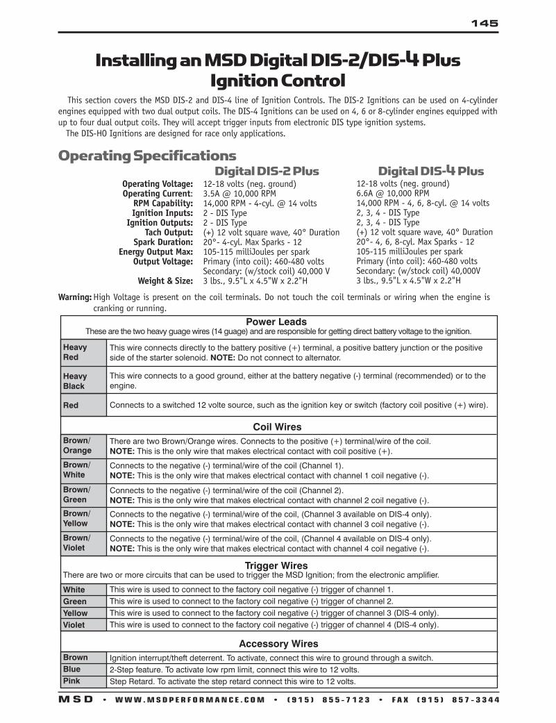
145
M S D • W W W . M S D P E R F O R M A N C E . C O M • ( 9 1 5 ) 8 5 5 - 7 1 2 3 • F A X ( 9 1 5 ) 8 5 7 - 3 3 4 4
Installing an MSD Digital DIS-2/DIS-4 Plus Ignition Control
This section covers the MSD DIS-2 and DIS-4 line of Ignition Controls. The DIS-2 Ignitions can be used on 4-cylinder engines equipped with two dual output coils. The DIS-4 Ignitions can be used on 4, 6 or 8-cylinder engines equipped with up to four dual output coils. They will accept trigger inputs from electronic DIS type ignition systems. The DIS-HO Ignitions are designed for race only applications.
12-18 volts (neg. ground)6.6A @ 10,000 RPM14,000 RPM - 4, 6, 8-cyl. @ 14 volts2, 3, 4 - DIS Type2, 3, 4 - DIS Type(+) 12 volt square wave, 40° Duration20°- 4, 6, 8-cyl. Max Sparks - 12105-115 milliJoules per sparkPrimary (into coil): 460-480 voltsSecondary: (w/stock coil) 40,000V3 lbs., 9.5"L x 4.5"W x 2.2"H
Operating Specifications Digital DIS-2 Plus Digital DIS-4 Plus
Warning: High Voltage is present on the coil terminals. Do not touch the coil terminals or wiring when the engine is cranking or running.
This wire connects directly to the battery positive (+) terminal, a positive battery junction or the positive side of the starter solenoid. NOTE: Do not connect to alternator.
This wire connects to a good ground, either at the battery negative (-) terminal (recommended) or to the engine.
HeavyRed
Power LeadsThese are the two heavy guage wires (14 guage) and are responsible for getting direct battery voltage to the ignition.
HeavyBlack
Coil Wires
Connects to a switched 12 volte source, such as the ignition key or switch (factory coil positive (+) wire).Red
There are two Brown/Orange wires. Connects to the positive (+) terminal/wire of the coil. NOTE: This is the only wire that makes electrical contact with coil positive (+).
Brown/Orange
Connects to the negative (-) terminal/wire of the coil (Channel 1). NOTE: This is the only wire that makes electrical contact with channel 1 coil negative (-).
Brown/White
Connects to the negative (-) terminal/wire of the coil (Channel 2). NOTE: This is the only wire that makes electrical contact with channel 2 coil negative (-).
Brown/Green
Connects to the negative (-) terminal/wire of the coil, (Channel 3 available on DIS-4 only). NOTE: This is the only wire that makes electrical contact with channel 3 coil negative (-).
Brown/Yellow
Connects to the negative (-) terminal/wire of the coil, (Channel 4 available on DIS-4 only).NOTE: This is the only wire that makes electrical contact with channel 4 coil negative (-).
Brown/Violet
This wire is used to connect to the factory coil negative (-) trigger of channel 1.This wire is used to connect to the factory coil negative (-) trigger of channel 2.This wire is used to connect to the factory coil negative (-) trigger of channel 3 (DIS-4 only).This wire is used to connect to the factory coil negative (-) trigger of channel 4 (DIS-4 only).
WhiteGreenYellowViolet
Trigger WiresThere are two or more circuits that can be used to trigger the MSD Ignition; from the electronic amplifier.
Operating Voltage: 12-18 volts (neg. ground) Operating Current: 3.5A @ 10,000 RPM RPM Capability: 14,000 RPM - 4-cyl. @ 14 volts Ignition Inputs: 2 - DIS Type Ignition Outputs: 2 - DIS Type Tach Output: (+) 12 volt square wave, 40° Duration Spark Duration: 20°- 4-cyl. Max Sparks - 12 Energy Output Max: 105-115 milliJoules per spark Output Voltage: Primary (into coil): 460-480 volts Secondary: (w/stock coil) 40,000 V Weight & Size: 3 lbs., 9.5"L x 4.5"W x 2.2"H
BrownBluePink
Ignition interrupt/theft deterrent. To activate, connect this wire to ground through a switch.2-Step feature. To activate low rpm limit, connect this wire to 12 volts.Step Retard. To activate the step retard connect this wire to 12 volts.
Accessory Wires
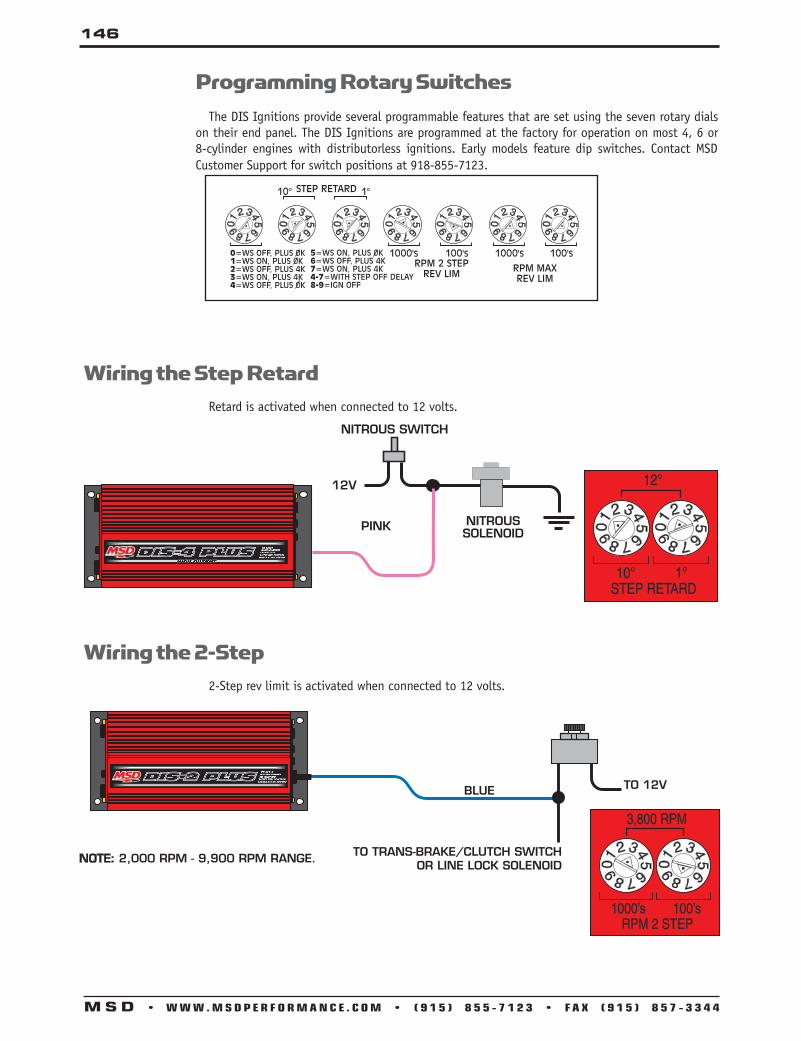
146
M S D • W W W . M S D P E R F O R M A N C E . C O M • ( 9 1 5 ) 8 5 5 - 7 1 2 3 • F A X ( 9 1 5 ) 8 5 7 - 3 3 4 4
Programming Rotary Switches The DIS Ignitions provide several programmable features that are set using the seven rotary dials on their end panel. The DIS Ignitions are programmed at the factory for operation on most 4, 6 or 8-cylinder engines with distributorless ignitions. Early models feature dip switches. Contact MSD Customer Support for switch positions at 918-855-7123.
Wiring the Step Retard Retard is activated when connected to 12 volts.
TO TRANS-BRAKE/CLUTCH SWITCHOR LINE LOCK SOLENOID
Wiring the 2-Step 2-Step rev limit is activated when connected to 12 volts.

147
M S D • W W W . M S D P E R F O R M A N C E . C O M • ( 9 1 5 ) 8 5 5 - 7 1 2 3 • F A X ( 9 1 5 ) 8 5 7 - 3 3 4 4
MSD DIS-2 to Typical 4-cylinder Ignition
NOTE: MSD offers a direct plug-in harness, PN 8883, for Dodge/Mitsubishi 4-tower coil pack.
MSD DIS-4 to Typical 6-cylinder Ignition

148
M S D • W W W . M S D P E R F O R M A N C E . C O M • ( 9 1 5 ) 8 5 5 - 7 1 2 3 • F A X ( 9 1 5 ) 8 5 7 - 3 3 4 4
MSD DIS-4 with a Typical Distributorless V8 Ignition
GROUND
NOTE: MSD offers a direct plug-in Harness for Ford dual coil systems, PN 88812.

149
M S D • W W W . M S D P E R F O R M A N C E . C O M • ( 9 1 5 ) 8 5 5 - 7 1 2 3 • F A X ( 9 1 5 ) 8 5 7 - 3 3 4 4
MSD DIS-2 with PN 8870, Coil Spacers for GM applications
BLUE - 2-STEP (TO GROUND)
BROWN - IGNITION INTERRUPT (TO GROUND)
PINK - STEP RETARD
NOTE: OEM wiring is inconsistent. Start by determining which factory terminal is the 12-volt source. The MSD wiring is dependent on the 12-volt source.

150
M S D • W W W . M S D P E R F O R M A N C E . C O M • ( 9 1 5 ) 8 5 5 - 7 1 2 3 • F A X ( 9 1 5 ) 8 5 7 - 3 3 4 4
Wiring an MSD Tach Adapter, PN 8912 and PN 89121 The PN 8912 is a dual channel adapter that will only be used with MSD line of DIS-2 or DIS-4 Ignition (the DIS-4 requires two). The Adapter has six wires that need to be connected and the DIS Ignition already has the matching connectors.
Black:Red:
Brown/White:Brown/Green:
White:Green:
Connects to Ground.Connects to 12 volts (ignition).Connects to the White wire going to the Coils and ECU.Connects to the Green wire going to the Coils and ECU.Connects to the White wire going to the MSD DIS Ignition. Connects to the Green wire going to the MSD DIS Ignition.
General Wiring
TO MSDDIS-2
BROWN/WHITE
TO COILSAND ECU
BLACK
WHITE
BROWN/GREEN GREEN
RED RED
GREEN GREEN
WHITE WHITE
GROUND
GROUND
MSD Tach Adapter, PN 8912, to DIS-4
MSD Tach Adapter, PN 8912, to DIS-2
*6-cylinder applications must ground the violet wire.

151
M S D • W W W . M S D P E R F O R M A N C E . C O M • ( 9 1 5 ) 8 5 5 - 7 1 2 3 • F A X ( 9 1 5 ) 8 5 7 - 3 3 4 4
Universal Boost Timing Master Using Points
BOOSTRETARD
0
1 2
3
BLACK
NOTE: MAKE SURE 12 VOLTS ARE PRESENTAT COIL POSITIVE TERMINAL
VIOLET
BLACK
TO VEHICLEGROUND
MAGNETICPICKUP
NOT USED
COIL
12V
WHITE
FROM POINTS
RED
ORANGE
PN 54701CABLE
GRAY
GREEN
IGN
AUTOTRONIC CONTROLS CORPORATION1490 HENRY BRENNAN DR.,TX 79936 (915) 857-5200
IGNITION
TM
BOOST
MASTERTIMING
PART NO. 8762
Boost Timing Master, PN 5462
The Universal Boost Timing Master, PN 5462, is a Timing Control and ignition enhancer in-one. It allows you to adjust the timing up to 15° as the boost pressure of the turbo or supercharger increases. It also increases the stock inductive ignition spark energy and voltage creating a powerful spark to completely ignite the fuel mixture. The Universal BTM con-nects to most single coil factory and aftermarket ignition amplifiers and points style distributors. It can also be used as a stand alone ignition with an MSD Distributor.
Wire F unctions Black and Gray: These wires are routed together into a Weathertight Connector to hook to the Ad-
justable Timing Control Knob. Orange: Connects to the coil negative (-) terminal. Red: Connects to the original switched 12 volt wire that used to connect to the coil posi-
tive (+) terminal. With the BTM, the wires hook together, but not on the coil terminal. Black: Connects to engine or chassis ground. Violet: The supplied violet jumper connects from the battery positive (+) terminal to the
coil (+) terminal. White: This is the trigger signal wire and connects to the points or electronic ignition
trigger wire. Magnetic Connector: This connector is used when triggering the ignition from a magnetic pickup. Violet: Magnetic pickup positive (+). Green: Magnetic pickup negative (-).
NOTE: If you are already using an MSD 6, 7, 8, or 10 Ignition Control, use BTM, PN 8762.
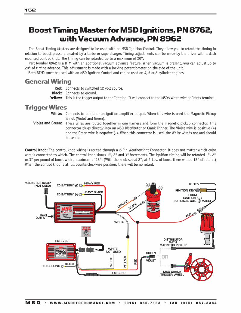
152
M S D • W W W . M S D P E R F O R M A N C E . C O M • ( 9 1 5 ) 8 5 5 - 7 1 2 3 • F A X ( 9 1 5 ) 8 5 7 - 3 3 4 4
General Wiring
Trigger Wires
The Boost Timing Masters are designed to be used with an MSD Ignition Control. They allow you to retard the timing in relation to boost pressure created by a turbo or supercharger. Timing adjustments can be made by the driver with a dash mounted control knob. The timing can be retarded up to a maximum of 20°. Part Number 8962 is a BTM with an additional vacuum advance feature. When vacuum is present, you can adjust up to 20° of timing advance. This adjustment is made with a locking potentiometer on the side of the unit. Both BTM’s must be used with an MSD Ignition Control and can be used on 4, 6 or 8-cylinder engines.
Boost Timing Master for MSD Ignitions, PN 8762, with Vacuum Advance, PN 8962
White:
Violet and Green:
Connects to points or an ignition amplifier output. When this wire is used the Magnetic Pickup is not (Violet and Green). These wires are routed together in one harness and form the magnetic pickup connector. This connector plugs directly into an MSD Distributor or Crank Trigger. The Violet wire is positive (+) and the Green wire is negative (-). When this connector is used, the White wire is not and should be sealed.
Control Knob: The control knob wiring is routed through a 2-Pin Weathertight Connector. It does not matter which color wire is connected to which. The control knob shows 1°, 2° and 3° increments. The ignition timing will be retarded 1°, 2° or 3° per pound of boost with a maximum of 15°. (With the knob set at 2°, at 6-Lbs. of boost there will be 12° of retard.) When the control knob is at full counterclockwise position, there will be no retard.
AUTOTRONIC CONTROLS CORPORATION1490 HENRY BRENNAN DR.,TX 79936 (915) 857-5200
IGNITION
TM
BOOST
MASTERTIMING
PART NO. 8762
DISTRIBUTOR
VIOLET
FROMIGNITION KEY
(ORIGINAL COIL WIRE)
IGNITION KEY
RED
TO 12V
ORGREEN
DISTRIBUTORWITH
MAGNETIC PICKUP
MSD CRANKTRIGGER WHEEL
+
BLACK WH
ITE
WHITE
RED
YELL
OW
WHITENOT USED
TO GROUND
PN 8762
PN 8860
ORANGE
BLACK
BOOSTRETARD
0
1 2
3
AUTOTRONIC CONTROLS CORPORATION
SERIAL NO..IGNITION
PART NO.
AUTOTRONIC CONTROLS CORPORATION
SERIAL NO..IGNITION
PART NO.
Connects to switched 12 volt source. Connects to ground. This is the trigger output to the Ignition. It will connect to the MSD’s White wire or Points terminal.
Red:Black:
Yellow:

153
M S D • W W W . M S D P E R F O R M A N C E . C O M • ( 9 1 5 ) 8 5 5 - 7 1 2 3 • F A X ( 9 1 5 ) 8 5 7 - 3 3 4 4
The PN 8680 Timing Control easily connects to an MSD Ignition. Timing adjustments can be made by the driver with a dash mounted control knob. The timing can be retarded up to 15°. When the control knob is at full clockwise position, the timing will be at the factory setting.
General Wiring
Trigger Wires
Magnetic Pickup Loop: When used with a magnetic pickup, a white wire loop must be cut. The loop is with the cylinder select loops.
Control Knob: The control knob wiring is routed through a 2-Pin Weathertight Connector. It does not matter which color wire is connected to which.
Cylinder Select: There are two wire loops under the small cover on the side of the control. For 6-cylinder operation, cut the Red loop, for 4-cylinder engines, cut both the Red and Blue loop.
Adjustable Timing Control, PN 8680
Connects to switched 12 volt source. Connects to ground. This is the trigger output to the Ignition. It will connect to the MSD’s White wire or Points terminal.
White:
Violet and Green:
Connects to points or an ignition amplifier output. When this wire is used the Magnetic Pickup is not (Violet and Green). These wires are routed together in one harness and form the magnetic pickup connector. This connector plugs directly into an MSD Distributor or Crank Trigger. The Violet wire is positive (+) and the Green wire is negative (-). When this connector is used, the White wire is not and should be sealed.
DISTRIBUTOR
FROMIGNITION KEY
(ORIGINAL COIL WIRE)
IGNITION KEY
RED
TO 12V
ORGREEN
VIOLET
DISTRIBUTORWITH
MAGNETIC PICKUP
MSD CRANKTRIGGER WHEEL
DISTRIBUTOR
+
BLACK
WH
ITE
WHITE
RED
YELL
OW
WHITENOT USED
TO GROUND
TIMINGCONTROLPN 8680
PN 8860
A DVA N C E
ORANGE
BLACK
AUTOTRONIC CONTROLS CORPORATION
SERIAL NO..IGNITION
PART NO.
AUTOTRONIC CONTROLS CORPORATION
SERIAL NO..IGNITION
PART NO.
135
7 9 111315
ADVANCE
TIMINGCONTROLTIMINGCONTROL
PN 8680 to Magnetic Pickup
Red:Black:
Yellow:

154
M S D • W W W . M S D P E R F O R M A N C E . C O M • ( 9 1 5 ) 8 5 5 - 7 1 2 3 • F A X ( 9 1 5 ) 8 5 7 - 3 3 4 4
3-Stage Retard, PN 8970, and Multi-Step Retard, PN 8972
Red:Black:
Yellow:
Connects to switched 12 volt source. Connects to ground. This is the trigger output to the Ignition. It will connect to the MSD’s White wire or Points terminal.
White:
Violet and Green:
Connects to points or an ignition amplifier output. When this wire is used the Magnetic Pickup is not (Violet and Green). These wires are routed together in one harness and form the magnetic pickup connector. This connector plugs directly into an MSD Distributor or Crank Trigger. The Violet wire is positive (+) and the Green wire is negative (-). When this connector is used, the White wire is not and should be sealed.
General Wiring
Trigger Wires
The 3-Stage Retard, PN 8970, supercedes the Multi-Step Retard, PN 8972. They both are designed to provide up to three different retard rates that can be activated at different times. The three stages are cumulative up to 20° (6° on first stage, 4° second, 2° third means 12° total). There are three retard module sockets on the side of the unit, each with their own activation wire. Each stage is activated when the corresponding wire is removed from ground. If a stage is not going to be used, its activation wire MUST be con-nected to ground, or a Zero degree rpm module MUST be installed.
Activation Wires
Start Retard
Brown:Orange:
Gray:
When removed from ground, the FIRST stage is activated. When removed from ground, the SECOND stage is activated.When removed from ground, the THIRD stage is activated.
NOTE: If a stage is not going to be used, the wire must be grounded or a Zero degree module must be installed.
Violet:
Violet Loop:
Activates the start retard when supplied with 12 volts. The PN 8970 will automatically deactivate the retard once the engine reaches over 1300 rpm and will not return again until the ignition is turned Off or engine rpm drops below 400 rpm. The PN 8972 requires momentary 12 volts to activate and will deactivate when 12 Volts are removed. Under the cover next to the Blue and Red cylinder loops is a Violet loop. This adjusts the start retard of the PN 8970 only. When it is not cut, the retard is 10°, cutting it will retard it 25°.
Cylinder Select: There are two wire loops under the small cover on the side of the control. For 6-cylinder operation, cut the Red loop, for 4-cylinder engines, cut both the Red and Blue loop.

155
M S D • W W W . M S D P E R F O R M A N C E . C O M • ( 9 1 5 ) 8 5 5 - 7 1 2 3 • F A X ( 9 1 5 ) 8 5 7 - 3 3 4 4
DISTRIBUTOR
STARTERSOLENOID(FOR RETARD)
BLA
CK
WH
ITE
WH
ITE
RED
RED
NOTUSED
ORANGE
BLACK
SWITCHED 12 VOLTSFROM IGNITION KEY
MAGNETICPICKUP
YELL
OW
VIOLETBROWN
ORANGE
+TO BATTERY
TO BATTERYHEAVY BLACK
HEAVY RED
12VACTIVATION12V
ACTIVATION
STAGE 1NITROUSSOLENOID
STAGE 2NITROUSSOLENOID
GRAY
STAGE 3NC MICRO SWITCHON SHIFTER FOR
HIGH GEAR
ORDISTRIBUTOR
Timing Control, PN 8970, PN 8972
RETARD WIRE
12VACTIVATION
BUTTON
NITROUSSOLENOID
SOLENOIDWINDINGS
By connecting the retard wire to the 12 volt activation wire of the nitrous solenoid, the wire recieves a ground path through the windings of the solenoid. When the activation button is pressed, 12 volts is applied to the wire, thus removing the ground path and activating the retard stage.
Connecting a Retard Stage Through a Nitrous Solenoid
NOTE: ANY RETARD WIRE THAT IS NOT USED MUST BE GROUNDED.

156
M S D • W W W . M S D P E R F O R M A N C E . C O M • ( 9 1 5 ) 8 5 5 - 7 1 2 3 • F A X ( 9 1 5 ) 8 5 7 - 3 3 4 4
Red:Black:
Yellow:
Connects to switched 12 volt source. Connects to ground. This is the trigger output to the Ignition. It will connect to the MSD’s White wire or Points ter-minal.
White:
Violet and Green:
Connects to points or an ignition amplifier output. When this wire is used the Magnetic Pickup is not (Violet and Green). These wires are routed together in one harness and form the magnetic pickup connector. This connector plugs directly into an MSD Distributor or Crank Trigger. The Violet wire is positive (+) and the Green wire is negative (-). When this connector is used, the White wire is not and should be sealed.
General Wiring
Trigger Wires
The Digital Retard Control, PN 8975, provides up to four different retard rates that can be activated at different times. The four stages are cumulative up to 20° (6° on first stage, 4° second, 3° third, 2° fourth produces 15° total). Instead of using rpm modules, this unit has four rotary dials that range from 0°-9° in one degree increments. Each stage is activated when the corresponding wire is removed from ground. If a stage is not going to be used, its activation wire MUST be connected to ground, or positioned at zero on its dial. Any time a setting is changed with a rotary dial, the ignition must be turned Off/On to reset.
Activates the start retard when supplied to 12 volts. Once the engine reaches over 800 rpm, the retard will be deactivated and will not return again until the ignition is turned Off or engine rpm drops below 500 rpm. There is a rotary dial that controls the amount of retard in 5° increments with a max of 20°.
Cylinder Select A rotary dial is used to select the number of cylinders.
Magnetic Pickup Compensation This circuit provides a timing compensation circuit for different style pickups. This adjustment is more important for crank triggers and locked-out timing systems. If you are using the White wire for a trigger input, no adjustment is necessary.
Activation WiresWhen removed from ground, the FIRST stage is activated. When removed from ground, the SECOND stage is activated.When removed from ground, the THIRD stage is activated.When removed from ground, the FOURTH stage is activated.
Brown:Orange:
Gray:Dark Blue:
NOTE: If a stage is not going to be used, the wire should be grounded or the rotary switch must be turned to Zero.
Start Retard
Installing a Digital Retard Control, PN 8975

157
M S D • W W W . M S D P E R F O R M A N C E . C O M • ( 9 1 5 ) 8 5 5 - 7 1 2 3 • F A X ( 9 1 5 ) 8 5 7 - 3 3 4 4
Digital Multi-Retard, PN 8975
DISTRIBUTOR
TM
DIGITALMULTI-RETARD
SWITCHED 12 VOLTSFROM IGNITION KEY
WH
ITE
RED
RED
BLACK
NOT USED
ORANGE PRO POWERCOIL
WH
ITE
WHITE NOT USEDBLACK
TO GROUND
YELLOW
HEAVY RED
HEAVY BLACK
ORGREEN
VIOLET
DISTRIBUTORWITH
MAGNETIC PICKUP
MSD CRANKTRIGGER WHEEL
TO BATTERY
TO BATTERY
+
DARK BLUE4th STAGE
NOT USED(GROUND) BROWN 1st STAGE
2nd STAGE
ORANGE
12VACTIVATION12V
ACTIVATION
STAGE 1NITROUSSOLENOID
STAGE 2NITROUSSOLENOID
GRAY3rd STAGE
NC MICRO SWITCHON SHIFTER FOR
HIGH GEAR
ST AR TRE TA RDSTEP RE TA RD
0-4 CY L1-6 CY L2-8 CY L3-6 OD D
0-ZE RO1-5 DE G
2-10 DE G
3-15 DE G4-20 DE G5-25 DE G
1 2 3 4 MAG COMP6-FORD8-GM0-CRANK
01
2 3 4
6789
5 01
2 3 4
6789
5 0 0 0 01 1 1 12 2 2 23 3 3 34 4 4 4
6 6 6 6
7 7 7 78 8 8 89 9 9 9
5 5 5 5
01
2 3 4
6789
5
CYLINDERSELECT DIAL
BROWNWIRE
ORANGEWIRE
START RETARDWHEN THE ENGINE IS
CRANKING, THE TIMINGWILL RETARD THE SETAMOUNT. AT 800 RPM
THE RETARD ISDEACTIVATED
GRAYWIRE
DARK BLUEWIRE MAGNETIC PICKUP COMPENSATION
.
MAGNETIC PICKUPS HAVE DIFFERENTTHRESHOLDS. THIS ADJUSTMENT WILL
PROVIDE THE BEST COMPENSATIONFOR YOUR APPLICATION
Digital Multi-Retard to Magnetic Pickup

158
M S D • W W W . M S D P E R F O R M A N C E . C O M • ( 9 1 5 ) 8 5 5 - 7 1 2 3 • F A X ( 9 1 5 ) 8 5 7 - 3 3 4 4
Installing a Timing Computer, PN 8980 The MSD Timing Computer has a built-in timing curve designed for engines with locked-out timing. It is an electronic version of a centrifugal advance. When the engine is cranking the timing retards 20° from the mechanical locked out timing and remains there until 1,000 rpm. At this point, the tim-ing begins to ramp back up and reaches your mechanical setting by 3,000 rpm. This curve is not adjustable. This Control also has a single stage of retard that is adjustable with plug-in modules.
Red:Black:
Yellow:
Connects to switched 12 volt source. Connects to ground. This is the trigger output to the Ignition. It will connect to the MSD’s White wire or Points terminal.
White:
Violet and Green:
Connects to points or an ignition amplifier output. When this wire is used the Magnetic Pickup is not (Violet and Green). These wires are routed together in one harness and form the magnetic pickup connector. This connector plugs directly into an MSD Distributor or Crank Trigger. The Violet wire is positive (+) and the Green wire is negative (-). When this connector is used, the White wire is not and should be sealed.
General Wiring
Trigger Wires
Retard Stage There is a Gray and Black wire routed together into a 2-pin connector. The Gray is the activation wire for the retard stage. The black is a ground wire.
When this wire is removed from ground, the retard stage is activated. This is a ground wire. By connecting this to the Gray wire, the retard will not activate. A mating connector is supplied to jump the two together
Gray:Black:
DISTRIBUTOR
HEAVY RED
TO GROUND
NOT USED
WH
ITE
WH
ITE
TIMINGCONTROLPN 8980
SWITCHED 12 VOLTSFROM IGNITION KEY
YELL
OW
RED
RED
BLACK
NOTUSED
ORANGE
HEAVY BLACK
PRO POWER COILPN 8201+
GRAY
ORGREEN
VIOLET
12VACTIVATION
STAGE 1NITROUSSOLENOID
+TO BATTERY
TO BATTERY
CYLINDERS864
CUT LOOPSNONERED
RED & BLUE
Note: Magnetic pickup loop must be cut. See Page 141.
Timing Computer, PN 8980

159
M S D • W W W . M S D P E R F O R M A N C E . C O M • ( 9 1 5 ) 8 5 5 - 7 1 2 3 • F A X ( 9 1 5 ) 8 5 7 - 3 3 4 4
Installing a Programmable Timing Control, PN 8981
The MSD Programmable Timing Control allows you to program an advance curve for engines with locked-out timing. It is a programmable electronic version of a centrifugal advance. There is also an optional single stage of retard and 20° start retard. The timing curve is programmed with three locking potentiometers. When all of the pots are turned to full clockwise position, there is no timing curve. This is where you should begin all adjustments. The total timing must be set in the engine before beginning any adjustments.
Retard Stage There is a single stage of retard that is activated when the Gray wire is removed from ground. The amount of retard is adjustable with plug-in modules. When the retard is not being used, the Gray wire MUST be grounded or a Zero degree module must be installed.
Gray: When this wire is removed from ground, the retard stage is activated.
Red:Black:
Yellow:
Connects to switched 12 volt source. Connects to ground. This is the trigger output to the Ignition. It will connect to the MSD’s White wire or Points terminal.
White:
Violet and Green:
Connects to points or an ignition amplifier output. When this wire is used the Magnetic Pickup is not (Violet and Green). These wires are routed together in one harness and form the magnetic pickup connector. This connector plugs directly into an MSD Distributor or Crank Trigger. The Violet wire is positive (+) and the Green wire is negative (-). When this connector is used, the White wire is not and should be sealed.
General Wiring
Trigger Wires
Start Retard When 12 volts is present on the Violet wire, the timing will be retarded 20° during cranking.
Violet: Activates 20° of retard when connected to 12 volts. Connect to the starter side of the starter solenoid wiring.

160
M S D • W W W . M S D P E R F O R M A N C E . C O M • ( 9 1 5 ) 8 5 5 - 7 1 2 3 • F A X ( 9 1 5 ) 8 5 7 - 3 3 4 4
Timing Computer, PN 8981
DISTRIBUTOR
HEAVY RED
TO GROUND
NOT USED
WH
ITETIMING
CONTROLPN 8981
SWITCHED 12 VOLTSFROM IGNITION KEY
YELL
OW
RED
RED
BLACK
NOTUSED
ORANGE
HEAVY BLACK
PRO POWER COILPN 8201+
GRAYBLACK
VIOLETTO STARTERSOLENOID(FOR START RETARD)
ORGREEN
VIOLET
DISTRIBUTORWITH
MAGNETIC PICKUP
12VACTIVATION
STAGE 1NITROUSSOLENOID
+TO BATTERY
TO BATTERY
CYLINDERS864
CUT LOOPSNONERED
RED & BLUE
All adjustments of the Timing Computer are taken from your Mechanical, or total timing setting. The Me-chanical timing is set by the position of the crank trigger or distributor. Before making any adjustments, be sure to have your mechanical timing set to your specifications.
RPM: This is the rpm point in which the advance will begin. To set this, accelerate the engine to the rpm point that you want the advance to start. Turn the RPM control pot counterclockwise until the timing begins to change.
Initial Timing: This adjusts the timing setting where the engine idles. This amount can be ad-justed 20° from where the me-chanical timing is set. To adjust the initial timing, turn the con-trol pot counterclockwise. It will retard the timing up to 20° from the mechanical timing.
Slope: This is the point where the timing advances to the mechanical timing again. To set this, rev the engine up to the rpm point that the timing should be completely in at. Turn the Slope control pot counter-clockwise until the timing be-gins to change.

161
M S D • W W W . M S D P E R F O R M A N C E . C O M • ( 9 1 5 ) 8 5 5 - 7 1 2 3 • F A X ( 9 1 5 ) 8 5 7 - 3 3 4 4
Installing a Start/Retard Control, PN 8982 The MSD Start Retard Control provides a start retard and a single stage of retard. The start retard can be set for 10° or 25° during cranking. When the engine is cranked, the timing will retard until the engine reaches over 1,300 rpm. At this point it will return and stay at the set timing. There is also a step retard that is adjustable with plug-in modules. This retard is controlled by the Gray wire. It will be activated when the Gray wire is removed from ground. The PN 8982 must be used with an MSD Ignition Control and can be used on 4, 6 or 8-cylinder engines.
Start Retard
Retard Stage There is a single stage of retard that is activated when the Gray wire is removed from ground. When the retard is not being used, the Gray wire MUST be grounded or a Zero degree module must be installed.
Gray: When this wire is removed from ground, the retard stage is activated.
Red:Black:
Yellow:
Connects to switched 12 volt source. Connects to ground. This is the trigger output to the Ignition. It will connect to the MSD’s White wire or Points ter-minal.
White:
Violet and Green:
Connects to points or an ignition amplifier output. When this wire is used the Magnetic Pickup is not (Violet and Green).These wires are routed together in one harness and form the magnetic pickup connector. This connector plugs directly into an MSD Distributor or Crank Trigger. The Violet wire is positive (+) and the Green wire is negative (-). When this connector is used, the White wire is not and should be sealed.
General Wiring
Trigger Wires
Violet:
Violet Loop:
Activates the start retard when supplied to 12 volts. Once the engine reaches over 1,300 rpm, the retard will be deactivated and will not return again until the ignition is turned Off or engine rpm drops below 400 rpm. Under the cover next to the Blue and Red cylinder loops is a Violet loop. This adjusts the start retard. When it is not cut, the retard is 10°, cutting it will retard it 25°.
VIOLET LOOP(START RETARD)
RED LOOPBLUE LOOP
HIGH SPEEDRETARD MODULE
RETARD1025
CUT LOOPNONEVIOLET
CYLINDERS864
CUT LOOPSNONERED
RED & BLUE

162
M S D • W W W . M S D P E R F O R M A N C E . C O M • ( 9 1 5 ) 8 5 5 - 7 1 2 3 • F A X ( 9 1 5 ) 8 5 7 - 3 3 4 4
Start/Retard Control, PN 8982, with Magnetic Pickup
DISTRIBUTORTACH
C+
C-
IGN
PTS
M+
M-
HEAVY RED
TO GROUND
NOT USED
WH
ITESTART/RETARD
CONTROL
SWITCHED 12 VOLTSFROM IGNITION KEY
YELL
OW
RED
RED
BLACK
NOTUSED
ORANGE
HEAVY BLACK
PRO POWER COILPN 8201+
GRAY
VIOLETTO STARTERSOLENOID(FOR START RETARD)
ORGREEN
VIOLET
DISTRIBUTORWITH
MAGNETIC PICKUP
12VACTIVATION
STAGE 1NITROUSSOLENOID
+TO BATTERY
TO BATTERY
CYLINDERS864
CUT LOOPSNONERED
RED & BLUE
HEAVY RED
TO GROUND
NOTUSED
NOT USED
WHITE
START/RETARDCONTROLPN 8982
SWITCHED 12 VOLTSFROM IGNITION KEY
YELL
OW
RED
RED
BLACK
NOTUSED
ORANGE
HEAVY BLACK
PRO POWER COILPN 8201+
GRAY
VIOLETBLACK
TO STARTERSOLENOID(FOR START RETARD)
GREEN
VIOLET
+TO BATTERY
TO BATTERY
CYLINDERS864
CUT LOOPSNONERED
RED & BLUE
Start/Retard Control, PN 8982, with White Wire Trigger

163
M S D • W W W . M S D P E R F O R M A N C E . C O M • ( 9 1 5 ) 8 5 5 - 7 1 2 3 • F A X ( 9 1 5 ) 8 5 7 - 3 3 4 4
Note #2 Tach Manufacturers Auto manufacturers use tachometers made by different tachometer manufacturers. Some will work when connected to the MSD Ignition Unit Tach Output Terminal, others may require an MSD Tach Adapter. Connect the tachometer trigger wire to the Tach Output Terminal of the MSD to determine if the tachometer is operating correctly. If it does not operate cor-rectly, go back to the chart to determine which MSD Tach Adapter should be used.
Tachometer Information
Note #1 Tachometer Types There are basically two types of tachometers: Current Triggered Tachometers and Voltage Triggered Tachometers. The type of tachometer that is on the vehicle may be recognized by the way it is connected to the ignition coil. The drawings below show two wiring diagrams to help in determining which type of tachometer is on the vehicle.
This diagram shows a typical wiring schematic for af-termarket tachometers. These tachometers will usually have three wires and sometimes a fourth for a panel light. The tach trigger wire is the wire that originally went from the Tachometer to the Negative side of the coil. With an MSD installed, remove the wire that is connected to the coil negative terminal and connect it to the MSD Tach Output Terminal as shown.
Tachometer Trigger Wire
Notes
Current Triggered Tach Voltage Triggered Tach

164
M S D • W W W . M S D P E R F O R M A N C E . C O M • ( 9 1 5 ) 8 5 5 - 7 1 2 3 • F A X ( 9 1 5 ) 8 5 7 - 3 3 4 4
Tachometer InformationNote #3 GM Inline Filters Many General Motors Corporation vehicles have an in-line filter that should be bypassed when the factory ta-chometer drops back to zero as the engine RPM is increas-ing.
The drawings at the right show what the filter might look like. Locate the filter by tracing the wire from the TACH Terminal on vehicles equipped with an HEI Igni-tion System. On vehicles equipped without an HEI, trace the wire from the coil negative terminal until the filter is found.
Disconnect both wires from the filter and leave discon-nected. Connect the wire going to the tachometer to the MSD Ignition Unit Tach Output Terminal as shown in this Figure.
Note #4 Current Triggered If the tachometer is connected to the positive side of the ignition coil, do not attempt to connect this tachom-eter to the tach output terminal on the MSD Unit.
See Note #1 for a diagram of an original current trig-gered tach. The tachometer is connected to the positive side of the ignition coil. The ballast resistor or resistance wire can be on either side of the coil.
The diagram to the right shows a Chrysler Dual Ballast Resistor being used with a WHITE Wire Triggered installa-tion. The Chrysler Dual Ballast Resistor is from a 1973 to 1976 Chrysler electronic ignition system and may be pur-chased from any auto parts store. The additional resistance may correct the tachometer function.
Tach Adapters
PN 8910 PN 8910EISPN 8920
PN 8912

165
M S D • W W W . M S D P E R F O R M A N C E . C O M • ( 9 1 5 ) 8 5 5 - 7 1 2 3 • F A X ( 9 1 5 ) 8 5 7 - 3 3 4 4
PN 8910
WHITE
RED
TACHTRIGGER WIRE
FROM IGNITIONKEY
INDICATES CONNECTION
TACH
RED
ORANGE
BLACK
WHITE
FROM POINTSOR ELECTRONIC
IGNITION AMPLIFIER
DIODE(SUPPLIED WITH
PN 8910)
AUTOTRONIC CONTROLS CORPORATION
SERIAL NO..IGNITION
PART NO.
AUTOTRONIC CONTROLS CORPORATION
SERIAL NO..IGNITION
PART NO.
MSD Tach Adapter, PN 8910, to Voltage Triggered Tach
AUTOTRONIC CONTROLS CORPORATION
SERIAL NO..IGNITION
PART NO.
AUTOTRONIC CONTROLS CORPORATION
SERIAL NO..IGNITION
PART NO.
MSD Tach Adapter, PN 8910EIS

166
M S D • W W W . M S D P E R F O R M A N C E . C O M • ( 9 1 5 ) 8 5 5 - 7 1 2 3 • F A X ( 9 1 5 ) 8 5 7 - 3 3 4 4
MSD Tach Adapter, PN 8920, to Current Triggered Tach
MSD Tach Adapter, PN 8920, to Voltage Triggered Tach
AUTOTRONIC CONTROLS CORPORATION
SERIAL NO..IGNITION
PART NO.
AUTOTRONIC CONTROLS CORPORATION
SERIAL NO..IGNITION
PART NO.
AUTOTRONIC CONTROLS CORPORATION
SERIAL NO..IGNITION
PART NO.
AUTOTRONIC CONTROLS CORPORATION
SERIAL NO..IGNITION
PART NO.

167
M S D • W W W . M S D P E R F O R M A N C E . C O M • ( 9 1 5 ) 8 5 5 - 7 1 2 3 • F A X ( 9 1 5 ) 8 5 7 - 3 3 4 4
The MSD Soft Touch Rev Control, PN 8728, is designed for inductive style ignition systems. It cannot be used with an MSD CD Ignition such as any 6 or 7-Series Ignition Control. The Rev Limit is set with plug-in rpm modules. When the rpm reaches the specified limit, the Control will randomly drop the spark to the cylinders to keep the rpm at the limit. If no module is installed, there will be no rev limit.
Wire F unctions
Cylinder Programming Loops: There are two wire loops, Red and Blue under a small cover on the side of the Control. For a 6-cylinder engine, cut the Red loop. For 4-cylinder applications, cut the Blue and Red loops.
NOTE: MSD also offers another Soft Touch Rev Control, PN 8738. This Con-trol can only be used with an MSD 6T, 6TN and 6 HVC Ignition Control.
NOTE: This Rev Control is not recommended for Chrysler Gold and Chrome Ignition boxes.
Soft Touch Rev Control, PN 8728, with Points/Amplifier Ignition
FROM POINTSOR AMPLIFIER
DISTRIBUTOR
RPMMODULE
INDICATESCONNECTION
TO IGNITION KEY 12V
PN 8728
WHITE
GREEN
BLACK
RED
NOT USED
TO GROUND
VIOLET
Soft Touch Rev Controls
Red: Connects to a switched 12 volt source. Black: Connects to ground.
Trigger Pickup Wires: Green: Connects to the coil negative (-) terminal. White: Connects to Points or Amplifier trigger wire. Violet: Connects to the magnetic pickup positive (+) wire.

168
M S D • W W W . M S D P E R F O R M A N C E . C O M • ( 9 1 5 ) 8 5 5 - 7 1 2 3 • F A X ( 9 1 5 ) 8 5 7 - 3 3 4 4
Soft Touch Rev Control, PN 8728, withFord Duraspark Ignition
Soft Touch Rev Control, PN 8728, with GM HEI

169
M S D • W W W . M S D P E R F O R M A N C E . C O M • ( 9 1 5 ) 8 5 5 - 7 1 2 3 • F A X ( 9 1 5 ) 8 5 7 - 3 3 4 4
SWITCH OR
MICRO SWITCHPN 8820
TO GROUND
TO 12V
RED
BLACK
TO MODULE SOCKET
TO LINE LOCKOR TRANS-BRAKE
SOLENOID
The MSD 2-Step, PN 8739, 3-Step, PN 8737, and Launch Control, PN 8735, Module Selectors allow you to switch between two or three different rpm or retard modules. The different modules are activated when 12 volts are applied to the cor-responding wire. They must be used with an MSD component equipped with a rev control or timing control module.
Wire F unctions Two Pin Connector: Plugs into the module holder of the MSD component. Black: Connects to engine ground. Red: Activation wire, when 12 Volts are applied. Blue: Activation wire (3-Step and Launch Control only), when 12 Volts are applied.
2-Step, PN 8739, Operation
When there is 12 volts applied to the Red wire, Module 1 is activated. When no voltage (grounded or open) is present on the Red wire, Module 2 is activated.
3-Step, PN 8737, Operation
When there is no voltage present on the Red or Blue wires, Module 2 is engaged. When there are 12 volts applied to the Red wire, Module 1 is activated. Where there are 12 volts applied to the Blue wire, Module 3 is activated. If the Red and Blue wires are activated at the same time, only Module 3 (Blue wire) will be activated. Module 3 over- rides the other modules.
Basic 2-Step Module Selector Installation When 12 volts are applied to the Red wire of the 2-Step (button depressed), Module 1 will be engaged. When the button is released, Module 2 will automatically engage.
2 and 3-Step Module Selectors
NOTE: This is the module socket in an RPM Switch, Rev Limiter or Timing Com-puter.

170
M S D • W W W . M S D P E R F O R M A N C E . C O M • ( 9 1 5 ) 8 5 5 - 7 1 2 3 • F A X ( 9 1 5 ) 8 5 7 - 3 3 4 4
3-Step to MSD 7AL-2
3-Step to Timing Control for Multiple Retards
AUTOTRONIC CONTROLS CORPORATION
SERIAL NO..IGNITION
PART NO.
AUTOTRONIC CONTROLS CORPORATION
SERIAL NO..IGNITION
PART NO.
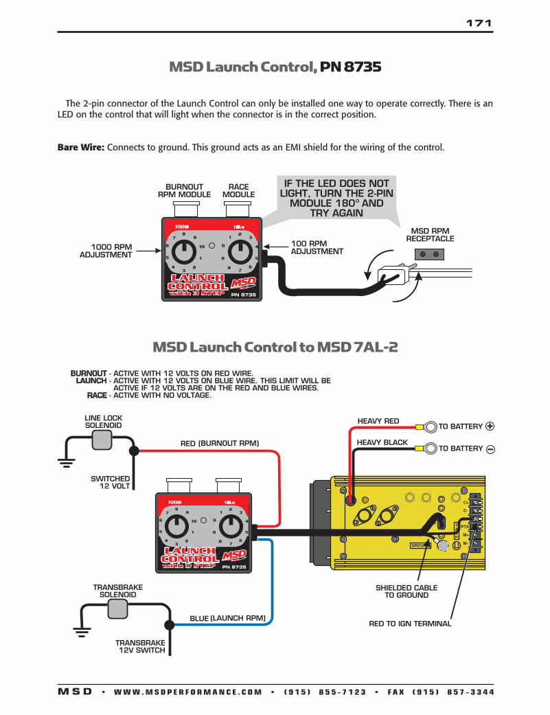
171
M S D • W W W . M S D P E R F O R M A N C E . C O M • ( 9 1 5 ) 8 5 5 - 7 1 2 3 • F A X ( 9 1 5 ) 8 5 7 - 3 3 4 4
MSD Launch Control to MSD 7AL-2
SHIELDED CABLETO GROUND
RED TO IGN TERMINAL
TRANSBRAKE12V SWITCH
SWITCHED12 VOLT
RED
BURNOUTLAUNCH
RACE
(BURNOUT RPM)
- ACTIVE WITH 12 VOLTS ON RED WIRE.- ACTIVE WITH 12 VOLTS ON BLUE WIRE. THIS LIMIT WILL BEACTIVE IF 12 VOLTS ARE ON THE RED AND BLUE WIRES.
- ACTIVE WITH NO VOLTAGE.
(LAUNCH RPM)BLUE
TRANSBRAKESOLENOID
LINE LOCKSOLENOID TO BATTERY
TO BATTERYHEAVY BLACK
HEAVY RED +
8
8
9
9
10
7
7
6 0
5
4
4
3
3
2
2
1
1
5
6
1000’s 100’s
PN 8735
LAUNCHCONTROLwith 3 STEPwith 3 STEP
MSD Launch Control, PN 8735
The 2-pin connector of the Launch Control can only be installed one way to operate correctly. There is an LED on the control that will light when the connector is in the correct position.
Bare Wire: Connects to ground. This ground acts as an EMI shield for the wiring of the control.
8
8
9
9
10
7
7
6 0
5
4
4
3
3
2
2
1
1
5
6
1000’s 100’s
PN 8735
LAUNCHCONTROLwith 3 STEPwith 3 STEP

172
M S D • W W W . M S D P E R F O R M A N C E . C O M • ( 9 1 5 ) 8 5 5 - 7 1 2 3 • F A X ( 9 1 5 ) 8 5 7 - 3 3 4 4
MSD 2-Step Launch Control forGM LS Series Engines, PN 8733
The MSD 2-Step Launch Control is designed for GM LS Series Engines with Coil-per-Cylinder ignitions. It can be used with 24x or 58x trigger wheels. The 2-Step Control will provide consistent launches and quick 60-foot times. RPM adjustments are made via two rotary switches located on the harness side of the unit. The adjustment range is from 1,000 - 10,900 rpm, in 100 and 1000 rpm increments. The LED will illuminate when the launch rev limit is active. Note that the 2-Step Launch Control is designed as a momentary low-rpm limiter. It will not provide, nor modify any over-rev protection.
NOTE: It is recommended to have the service manual for your vehicle.
The LS 2-Step has a built-in rpm drop circuit that prevents the low rpm limit from activating during gear shifts (when connected through the clutch switch). In order for the limit to activate, it must see an rpm drop of more than 1/3 the set amount. For example, if the limit is set at 3,000 rpm, the limiter will not activate unless it sees more than a 1,000 rpm drop.
Caution: Keeping the engine on a lower rpm limit may cause the Check Engine light to come on and could potentially damage the catalytic converter.
Activation Wire F unctionsThe launch rpm limit can be activated through a ground or a 12 volt source. Blue: When grounded, the launch feature will be active. White/Blue: When switched to 12 volts, the launch feature will be active.
LEDThe built-in LED will illuminate when the 2-Step Launch Control is activated.
Confirm InstallationWith the power On, engine running, activate the clutch or On/Off switch. If connected correct, the LED will illuminate when the clutch is activated. To verify the rpm, set the limit at a lower rpm, such as 3,000, and test the system.
Wiring the 2-Step Launch Control, PN 8733, Activation Wire
OR NOTE: DO NOT USE THE BLUE AND BLUE/WHITE WIRES AT THE SAME TIME.
BLUE - ACTIVATED WHEN GROUNDWHITE/BLUE - ACTIVATED W/12 VOLTS
COIL HARNESS
COIL PACKS
COIL HARNESS
COIL PACKS
NOTE: COIL HARNESSES ARE INTERCHANGEABLE
BLUE
WHITE/BLUECLUTCHSWITCH
CLUTCHSWITCH
12 VOLTS

173
M S D • W W W . M S D P E R F O R M A N C E . C O M • ( 9 1 5 ) 8 5 5 - 7 1 2 3 • F A X ( 9 1 5 ) 8 5 7 - 3 3 4 4
MSD 2-Step Launch Control forFord Mod Motors ‘99-On, PN 8734
Note that the 2-Step Launch Control is a low-rpm limiter that will not provide, nor modify any overrev protection. The stock high rpm rev limiter will still be active.
The MSD 2-Step Launch Control is designed for Ford Modular Engines with Coil-on-Plug ignitions. The 2-Step Control will provide consistent launches and quick 60-foot times. RPM adjustments are made via two rotary switches located on the harness side of the unit. The adjustment range is from 1,000 - 10,900 rpm, in 100 and 1000 rpm increment, and LED will illuminate when the launch rev limit is active.
NOTE: It is recommended to have the service manual for your vehicle.
NOTE: The engine rpm must drop more than one third of the set launchlimit in order to activate. For example, if the launch limit is set at 3,000 rpm, the engine speed must drop below 2,000 rpm in order for the launch limit to become active (one third of 3,000 rpm is a 1,000 rpm drop).
Caution: Keeping the engine on a lower rpm limit may cause the Check Engine light to come on and could potentially damage the catalytic converter.
Wire F unctions 8-Wire Connector Tan: Single Connections. 8-Wire Connector Red: 12-Volt Connection through this single Red wire. 3-Wire Connector Black: Connects to a good engine ground or the negative battery terminal. Blue: Activation Wire. When grounded, the launch feature will be active. White/Blue: Activation Wire. When switched to 12 volts, the launch feature will be active.
LED The built-in LED will illuminate when the 2-Step launch Control is activated. It will also, illuminate when there is no rpm signal.
1. Connect the 3-pin harness to the 2-Step and connect the Black wire to the good engine or chasis ground.2. Disconnect the 2-pin connectors from each of the eight ignition coils.3. Connect all eight of the 2-pin male connectors from the MSD harness into the factory coil connectors.4. Plug the 8-pin connector with the single Red wire from the 2-Step to the connector with Black wires.5. Turn the key to the On position - do NOT start the engine. Look at the LED on the 2-Step: LED On - This confirms that the wiring is correct and you can move to step 6 (See Wiring the 2-Step Launch Control). LED Off - The wiring is different for this application and needs to be changed. Turn the key Off, plug the 8-pin connector
with the eight Gray wires into the connector with the single Red wire (See Alternate Wiring).6. Connect the 8-pin harness with the tan wires to the remaining connector on the harness.7. Connect all eight of the female 2-pin connectors from the MSD harness into the factory coils.
Confirm Installation With the power On, engine running, activate the clutch or On/Off switch. If connected correct, the LED will illuminate when the clutch is activated. To verify the rpm, set the limit at a lower rpm, such as 3,000, and test the system. If the engine has troublt starting or running, check the following:•Groundorswitched12voltsconnection.•Coilconnections•Thetwo8-pinconnectorsmaybeinthewrongpositionandshouldbeswappedandtestedagain.

174
M S D • W W W . M S D P E R F O R M A N C E . C O M • ( 9 1 5 ) 8 5 5 - 7 1 2 3 • F A X ( 9 1 5 ) 8 5 7 - 3 3 4 4
GROUND
ACTIVATIONWIRES
WHITE BLUE
BLUEACTIVATES WITH 12 VOLTS
ACTIVATES WITH GROUND
TAN
RED
GRAY
BLACK
STEP 3
STEP 2
GROUND
TAN
RED
BLACK
GRAY
NOTE: IF THE LED DOESN'T TURN ON, AS DETAILED IN STEP 5, FOLLOW THIS DIAGRAM.
ACTIVATIONWIRES
WHITE BLUE
BLUEACTIVATES WITH 12 VOLTS
ACTIVATES WITH GROUND
OR
NOTE: DO NOT USE THE BLUE AND BLUE/WHITE WIRES AT THE SAME TIME.
BLUE - ACTIVATED WHEN GROUNDWHITE/BLUE - ACTIVATED W/12 VOLTS
Wiring the 2-Step Launch Control, PN 8734
Alternate Wiring for 2-Step Launch Control, PN 8734,
Activation Wiring for 2-Step Launch Control, PN 8734

175
M S D • W W W . M S D P E R F O R M A N C E . C O M • ( 9 1 5 ) 8 5 5 - 7 1 2 3 • F A X ( 9 1 5 ) 8 5 7 - 3 3 4 4
MSD RPM Activated Switches
NOT USEDGRAY
RED
WHITE
BLACK
YELLOW
TO GROUND
TO TACH TERMINALON MSD OR
COIL (-) IF AN MSDIGNITION IS NOT USED
TO SWITCHED 12V
+12 VOLTS
RPMMODULE
PN 7542SHIFT LIGHT
• INDICATES CONNECTIONCONSTANT GROUND
(ACTIVATION WIRE)
PN 8950
MSDPERFORMANCE.COM
RPM Activated Switch, PN 8950, to a Shift Light
This section covers the MSD RPM Activated Switch, PN 8950, and the Window Switch, PN 8956. The PN 8950 will activate a circuit at a desired rpm by supplying or removing ground. The PN 8956 Window Switch will activate a circuit by supplying ground, then will deactivate the same circuit at a different rpm. The MSD Switches are capable of switching approximately 2 amps continuously. If too much current or the circuit heats up over time, the Switches will shut off to prevent damage. For circuits that require more current for an extended time, MSD recommends a Relay. Page 128 shows a relay wiring example.
If no module is installed, the switch will not activate.
An RPM Activated Switch for magnetos is also available as PN 8957. It shares the same wiring as the PN 8950.
Wire F unctions Red: Connects to a switched 12 volt source. Black: Connects to ground. White: The rpm input wire that picks up engine rpm. It connects to the tach output terminal of an
MSD Ignition. When used with inductive or factory ignitions it connects to the coil negative terminal.
Activation Wires: Yellow: This wire is normally open and will switch to ground at your desired rpm to complete a circuit. Gray: This is on the PN 8950 only. This wire is normally closed to ground and will open a circuit at your
desired rpm.
Cylinder Programming Loops: There are two wire loops, Red and Blue, on the side of the Control. For a 6-cylinder en-gine, cut the Red loop. For 4-cylinder applications, cut the Blue and Red loops.
BLUERED
SEAL THE LOOP ENDSHEAT-SHRINK
CAP CYLINDER LOOP
CYLINDERS CUT LOOPS 8 NONE 6 RED 4 RED & BLUE

176
M S D • W W W . M S D P E R F O R M A N C E . C O M • ( 9 1 5 ) 8 5 5 - 7 1 2 3 • F A X ( 9 1 5 ) 8 5 7 - 3 3 4 4
RPM Activated Switch, PN 8950 to Timing Control Retard
RED
WHITE
BLACK
YELLOW
RETARDACTIVATION WIRE
INDICATES CONNECTIONS
GRAY
TO GROUND
NOT USED
TO TACH TERMINALON MSD OR
COIL (-) IF AN MSDIS NOT USED
TO SWITCHED 12V
MSD TIMING CONTROL
RPMMODULE
PN 8950
MSDPERFORMANCE.COM
RPM Activated Window Switch, PN 8956 to Activate Nitrous
YELLOW
RPMMODULES
BLACK
WHITE
RED
MSD RELAY PN 8960
GROUND
GROUND
NOS
NOS
(+) 12 VOLT
(+) 12 V
NORMAL OPEN
NORMAL CLOSEDCOMMONTO GROUND
12 V
S1 S2
GND
12 VOLTS
TO TACH TERMINALON MSD OR
COIL (-) IF AN MSDIS NOT USED
PN 8950
MSDPERFORMANCE.COM

177
M S D • W W W . M S D P E R F O R M A N C E . C O M • ( 9 1 5 ) 8 5 5 - 7 1 2 3 • F A X ( 9 1 5 ) 8 5 7 - 3 3 4 4
RPM Activated Window Switch, PN 8956
GROUND
RAS OUTPUT WIRE(YELLOW OR
BROWN/WHITE)
YELLOW
SHIFTER
87
87A
86
30
85
12V
RED 12VBLACK GROUND
GRAY(NOT USED)
PN 8950
MSDPERFORMANCE.COM
NOTE: This diagram illustrates wiring an air shifter that requires 12 volts to shift the transmission.
RPM Activated Window Switch, PN 8956, to Nitrous Relay with Trans Brake Interrupt
GROUND
GROUND
GROUND OR YELLOW WIREFROM RPM ACTIVATED SWITCH
YELLOW
2-STEP WIRE
87
87A
86
30
85
TRANS BRAKE (+) WIRE
NITROUS SOLENOID(S)WIRE (+)
87
87A
86
30
85
12V BATTERY
OR
WOT SWITCH
SWITCH
12V
INDICATES CONNECTION
PUSH BUTTON
RED 12V
BLACK GROUND
GRAY(NOT USED)
PN 8950
MSDPERFORMANCE.COM
Note: For more Nitrous drawings go to MSDFORUMS.COM

178
M S D • W W W . M S D P E R F O R M A N C E . C O M • ( 9 1 5 ) 8 5 5 - 7 1 2 3 • F A X ( 9 1 5 ) 8 5 7 - 3 3 4 4
MSD Relays will allow you to activate a variety of accessories that require high current. These are ideal to tie in with rpm activated switches such as nitrous or air shifter solenoids or even a horn or fuel pump.
The most common use of a relay is to switch the relay on (energize its coil) using a small amount of power (12V/1 amp) which then moves the relay’s armature so it can transfer a large amount of power (12V/30 amp) to the device which you need to activate.
• The PN 8960 will handle a 30 amp load, on each side, with an input voltage of 12 volts. • The PN 8961 Relay will handle a 30 amp load and is ideal for multiple accessories.
Relays have a variety of specifications to understand for your application. A few things to consider include:
• Make sure the Relay can accept and handle the voltage and current required to activate the desired circuit. • The number of bobbins to use with different circuits (generally 1-2).• The number of electrical contacts for the armature (generally 1-2). • If the Relay is Normally Open (NO) or Normally Closed (NC).
NO - NORMALLY OPENNC - NORMALLY CLOSEDC - COMMON
MSD Relays, Single Pole, PN 8961, Double Pole, PN 8960
MSD Relays
INSIDE
86
1 7
3 4 2
1 7 8 6
3 4 20
8 6
0
87 87A
87A
85 30
87 NO
NC C NO
NC
C
86 85
30
LOCATION OF PINS
MSD PN 8961 RELAY
MSD PN 8960 RELAY
Note: For more Nitrous drawings go to MSDFORUMS.COM

179
M S D • W W W . M S D P E R F O R M A N C E . C O M • ( 9 1 5 ) 8 5 5 - 7 1 2 3 • F A X ( 9 1 5 ) 8 5 7 - 3 3 4 4
87
86
3085
87a
TOGROUND
YELLOW
REDRELAYPN 8961
RED12 VOLTS
NITROUS ORAIR SHIFTSOLENOID
BLACKTO
GROUND
GRAY(NOT USED)
WHITE TOMSD TACHTERMINALOR COIL (-)
PN 8950
MSDPERFORMANCE.COM
87
86
3085
87a
FUEL PUMPSWITCH
12V
12V
TOGROUND
TOGROUND
FUELPUMP
MSD RPM Activated Switch, Solenoid and Relay, PN 8961
MSD Relay, PN 8961, to an Electric Fuel Pump
MSD Relay, PN 8961, 2-Step and Clutch Switch
BLACK
TOGROUND
RELAYPN 8961
REDJUMPER
(+) 12V
CLUTCHSWITCH
LINE LOCKSOLENOID
REV LIMITER
(+) 12V
IF YOUR APPLICATION REQUIRES USING THE CLUTCH FOR EVERY SHIFT,THIS DIAGRAM WILL PROVIDE A REV LIMIT ON THE LAUNCH ONLY ANDHOLD THE LINE LOCK ON UNTIL THE CLUTCH PEDAL IS RELEASED.
MOMENTARYPUSH BUTTON
SWITCH
TOGROUND
TOGROUND
87A
87 NO
NC
C
86 85
30

180
M S D • W W W . M S D P E R F O R M A N C E . C O M • ( 9 1 5 ) 8 5 5 - 7 1 2 3 • F A X ( 9 1 5 ) 8 5 7 - 3 3 4 4
MSD Shift Light, PN 8952
MSD Shift Light, PN 8952, to MSD Ignition
OR
SHIFT LIGHT
TACHOUTPUT
TERMINAL
TACHOUTPUT
BLACK TO GROUND
REDMSD 7, 8, OR 10-SERIES
MSD 6-SERIES
TO SWITCHED12 VOLTS
GREEN TO TACH OUTPUT
DIGITAL 6AL
REVLIMITER
This section covers the MSD Shift Light, PN 8952. The Light will activate at a desired rpm which is controlled by MSD’s white RPM Modules. If no rpm module is installed in the Light, it will not turn on. The Light can be used with stock igni-tions or with MSD Ignition Controls.
Wire F unctions Red: Connects to switched 12 volt source. Black: Connects to ground. Green: This is the rpm input wire that picks up engine rpm. It connects to the tach output terminal of an
MSD Ignition. When used with inductive or factory ignitions it connects to the coil negative terminal.
Cylinder Programming The Shift Light is programmed for 8-cylinder operation. There are three wire loops, that need to be modified for use on other engine configuration. For a 6-cylinder en-gine, cut one loop. Cut two loops for 4-cylinder engines and three loops for 2-cylinder engines.
Note: Once installed, whenever the ignition is turned On, the Shift Light will flash to confirm operation.

181
M S D • W W W . M S D P E R F O R M A N C E . C O M • ( 9 1 5 ) 8 5 5 - 7 1 2 3 • F A X ( 9 1 5 ) 8 5 7 - 3 3 4 4
MSD Shift Light, PN 8952, to Points/Amplifier Ignition
ORIGINAL12V IGNITION
WIRE
RED TO COIL (+)
GREEN TO COIL (-)
TOORIGINALPOINTS
OR AMPLIFIERTO GROUND
BLACK COIL
SHIFT LIGHT
MSD Shift Light, PN 8952, to Ford TFI Ignition
GREEN TO COIL
ORIGINAL12V IGNITION
WIRE
TOORIGINALPOINTS
OR AMPLIFIER
RED TO COIL
BLACK
+
+SHIFT LIGHT

182
M S D • W W W . M S D P E R F O R M A N C E . C O M • ( 9 1 5 ) 8 5 5 - 7 1 2 3 • F A X ( 9 1 5 ) 8 5 7 - 3 3 4 4
Digital Shift Light with Adjustable Intensity, PN 7542 This MSD Shift Light features two switches that allow the driver to control the LEDs' intensity. This unit is designed to be used with MSD's Programmable Series of Ignition Controls. It can also be used in conjunction with an RPM Activated Switch (such as MSD's PN 8950 or PN 8956).
WARNING: During installation, disconnect the battery cables. When disconnecting the battery, always remove the Negative cable first and install it last.
PN 7542SHIFT LIGHT
BLACKPROGRAMMABLE
SERIES MSD IGNITIONYELLOW
RED
ProgrammingTo change the intensity of the LEDs, turn the ignition On. Press either of the two buttons until the LEDs light on. Then, press or press and hold the + or - button to adjust the LEDs accordingly. When adjusted to your requirements, simply release the button and in two seconds the light will turn off and is programmed.
Wire F unctions Red: Connects to a switched 12 volts. Yellow: Activation wire. Connects to the Yellow wire of a Programmable Ignition or RPM
Activated Switch. Black: Connects to ground.
Connecting to a Programmable Ignition, PN 7542
BLACK
REDRED
ORANGEHEAVY RED
HEAVY BLACKBATTERYNEGATIVE
BATTERYPOSITIVE
MAGNETICPICKUP
WHITE
TO POINTSOR AMPLIFIERWHITE
BLACK
12 VOLTS
TO GROUND
TACHOUTPUT
COIL
RPMSWITCHPN 8950
YELLOW
PN 7542SHIFT LIGHT
RED
YELLOW BLACK
AUTOTRONIC CONTROLS CORPORATION
SERIAL NO..IGNITION
PART NO.
AUTOTRONIC CONTROLS CORPORATION
SERIAL NO..IGNITION
PART NO.
PN 8950
MSDPERFORMANCE.COM
Connecting with an RPM Activated Switch, PN 7542

183
M S D • W W W . M S D P E R F O R M A N C E . C O M • ( 9 1 5 ) 8 5 5 - 7 1 2 3 • F A X ( 9 1 5 ) 8 5 7 - 3 3 4 4
MSD Digital Shift Light, PN 89631
IMPORTANT: Do NOT connect to the coil (-) terminal. The supplied GMR pickup must be used when installing the Digital Shift Light unless the rpm signal is coming from the tach output of an MSD Ignition or aftermarket ECU. Dam-age to the DSL will occur if connected to a high voltage trigger source.
PROGRAMMINGBy pressing the two buttons simultaneously, you get the Shift Light into the different programming modes.
RPM: To adjust the rpm, press the two buttons until the rpm shows. Notice that all of the numbers flash. Adjust the rpm then push the two buttons again to move to the next mode. The rpm can be set up to 16,000 rpm. Once you go over 9,900 rpm, the display will show 1,000 indicating 10,000 rpm and higher.
Cylinder Count: The display will read CY and allow you to select between one to 12-cylinder engines using the Up/Down buttons. On single cylinder two stroke or four stroke applications that fire every revolution (waste spark systems) the shift light should be programmed for two cylinder operation for correct operation.
Intensity: Control the intensity of the LED and read out. Hold the buttons until LuL displays. Use the buttons to select from 9 (brightest) to 0 to turn off the shift light.
Self: Self mode will walk through all of the settings programmed into the light. It will first show the rpm shift value for the shift light, the cylinder count and light intensity. Start the test mode by pushing either button once Self is displayed. To reset the Self mode, push either button when SELF is displayed, or turn the power Off.
Each time the DSL is powered on, the LED will display the program values that are set.
UP
MODE
DOWN
PROGRAMMINGBUTTONS
RED TO SWITCHED 12 VOLTS
GREEN TO TACH SIGNAL
BLACK TO GROUND
PROGRAMMINGCY - Cylinder Count12, 10, 8, 6, 6 odd, 4, 2, 2 odd, 1
LuL - Light IntensityScale of 9-0 Bright to Dim
Use Up/Down buttons to adjust cylinders, intensity and rpm points.
INSTALLATION The Shift Light installs easily with the GMR Pickup or through the tach output terminal of an MSD Ignition Control or aftermarket ECU. It will accept a trigger signal rated from 0-24 volt amplitude. Never connect the Green Wire directly to the coil negative terminal.
If an ignition control or aftermarket ECU are not being used, the GMR pickup must be connected.

184
M S D • W W W . M S D P E R F O R M A N C E . C O M • ( 9 1 5 ) 8 5 5 - 7 1 2 3 • F A X ( 9 1 5 ) 8 5 7 - 3 3 4 4
MAGNETICCONNECTORNOT USED
TO BATTERY
WHITE
BLACK
ORANGE
WHITE
BLACK
ORANGE
RED
TO BATTERY
BLACK
TRIGGER INPUT
REDREDSWITCHED12 VOLT
GREEN
BLACK GROUND
COIL
OPTIONAL 2.2K RESISTORFOR NOISE FILTER
AUTOTRONIC CONTROLS CORPORATION
SERIAL NO..IGNITION
PART NO.
AUTOTRONIC CONTROLS CORPORATION
SERIAL NO..IGNITION
PART NO.
UP
MODE
DOWN
Wiring the MSD Digital Shift Light, PN 89631, with an MSD Ignition
BLACK GROUND
RED
GREEN
SWITCHED12 VOLT
SIGNALOUTPUT
GMR PICKUP
NOTE: The brass screw must be used for proper operation.
PRIMARY COIL (+) WIRE ORDIESEL INJECTOR 12 VOLT WIRE
WASHER MUST BE ON TOP OF METAL TABMETAL TAB
COILHARNESS
IGNITIONCOIL
IGNITIONCOIL
IGNITIONCOIL
IGNITIONCOIL
COIL (+)12 VOLTS
COIL (-)TRIGGER 4
COIL (-)TRIGGER 3
COIL (-)TRIGGER 2
COIL (-)TRIGGER 1
GMR PICKUP
GREEN
SHIFT LIGHT
BLACK GROUND
GMR PICKUP
UP
MODE
DOWN
GMR PICKUP INSTALLATIONThe MSD GMR pickup can be used with inductive or ca-pacitive ignition types to provide an rpm signal of 30% duration when the ignition coil fires. Two washers are provided with the pickup and must be installed in one of two positions depending on the type of ignition driving the coil. For late model applications, it is rec-ommended to have a wiring schematic of the vehicle’s ignition system. On some motorcycle and ATV appli-cations, the stock coils do not produce a long enough pulse. In these cases, loop the coil wire through the GMR pickup twice (See figure to the right).
PRIMARY COIL (+) WIRE
WASHER MUST BE ON TOP OF METAL TAB
METAL TAB
GMR PICKUP
Wiring the MSD Digital Shift Lifht, PN 89631, with an Inductive Coil-Per-Cylinder Ignition System .

185
M S D • W W W . M S D P E R F O R M A N C E . C O M • ( 9 1 5 ) 8 5 5 - 7 1 2 3 • F A X ( 9 1 5 ) 8 5 7 - 3 3 4 4
TO GROUNDON CYLINDER
HEAD
BLACK
RED
CHASSISGROUND
GMR PICKUP
NOTE: The brass screw must be used for proper operation.
PRIMARY COIL (+) WIRE ORDIESEL INJECTOR 12 VOLT WIRE
WASHER MUST BE ON TOP OF METAL TABMETAL TAB
BLACKGROUND
GMR PICKUPRED
GREEN
SWITCHED12 VOLT
GREEN
SHIFT LIGHT
BLACK GROUND
IGNITION
TM
UP
MODE
DOWN
Wiring the MSD Digital Shift Lifht, PN 89631, with Pro Mag 44 Electronic Points Box
MSD GMR Pickup, PN 8918/PN 89181
The MSD GMR pickup can be used with inductive or capacitive ignition types to provide an rpm signal of 30% duration when the ignition coil fires. Two washers are provided with the pickup and must be installed in one of two positions de-pending on the type of ignition driving the coil.
Note: For late model applications, it is recommended to have a wiring schematic of the vehicle’s ignition system.
Capacitive Discharge Ignitions For a CD Ignition such as an MSD, the two washers should be installed under the metal tab to provide a small air gap between the metal tab and the pickup sensor (Figure 1). Refer to note on Figure 2 for RPM Device programming.
Inductive Coil per Cylinder Ignition For an inductive ignition (mostly stock applications) the metal tabs must make contact, therefore no washer is required. There should be no air gap between the metal tab and the pickup sensor (Figure 2). Refer to note on Figure 3 for RPM Device programming.
Distributorless Coil PacksOn distributorless applications, the GMR pickup must be installed on the primary lead going to one of the coils. If the pickup is installed on the main ignition +12v wire feeding more than one coil, the pickup may not operate correctly at high speeds because of overlapping coil dwell current failing to fall to zero current between coil operating cycles (Figure 3). Refer to note on Figure 3 for RPM Device programming.

186
M S D • W W W . M S D P E R F O R M A N C E . C O M • ( 9 1 5 ) 8 5 5 - 7 1 2 3 • F A X ( 9 1 5 ) 8 5 7 - 3 3 4 4
BLACK GROUND
TO BATTERY
WHITE
BLACK
ORANGE
WHITE
BLACK
ORANGE
RED
TO BATTERY
BLACK
TRIGGER INPUT
GMR PICKUPRED
REDRED
GREEN
SWITCHED12 VOLT
SIGNALOUTPUT
GREEN
CD IGNITION PRIMARY COIL (+) WIRE(MSD - ORANGE)
BOTH WASHERS MUST BE UNDER METAL TAB
METAL TAB
GMR PICKUP
NOTE: The brass screw must be used for proper operation.
TO RPM ACTIVATED DEVICE
AUTOTRONIC CONTROLS CORPORATION
SERIAL NO..IGNITION
PART NO.
AUTOTRONIC CONTROLS CORPORATION
SERIAL NO..IGNITION
PART NO.
BLACK GROUND
GMR PICKUPREDRED
GREEN
SWITCHED12 VOLT
SIGNALOUTPUT
GREEN
GMR PICKUP
NOTE: The brass screw must be used for proper operation.
PRIMARY COIL (+) WIRE ORDIESEL INJECTOR 12 VOLT WIRE
BOTH WASHERS MUST BE ON TOP OF METAL TABMETAL TAB
COILHARNESS
IGNITIONCOIL
IGNITIONCOIL
IGNITIONCOIL
IGNITIONCOIL
COIL (+)12 VOLTS
COIL (-)TRIGGER 4
COIL (-)TRIGGER 3
COIL (-)TRIGGER 2
COIL (-)TRIGGER 1
GMR PICKUP
TO RPM ACTIVATEDDEVICE
Note: The device that the green signal output wire is at-tached must be programmed for 4, 6 or 8-cylinder depending on application.
Note: The device that the green signal output wire is attached must be programmed for single (1) cylinder operation.
Installation of MSD GMR Pickup, PN 8918, with a Capacitive Discharge Ignition Control
Installation of MSD GMR Pickup, PN 8918, with an Inductive Distributorless Ignition System

187
M S D • W W W . M S D P E R F O R M A N C E . C O M • ( 9 1 5 ) 8 5 5 - 7 1 2 3 • F A X ( 9 1 5 ) 8 5 7 - 3 3 4 4
Installation of MSD GMR Pickup, PN 8918, with a Distributorless Ignition Control
Installation of MSD GMR Pickup, PN 8918, with an Injector System
BLACK GROUND
RED RED
GREEN
SWITCHED12 VOLT
SIGNALOUTPUT
GREEN
GMR PICKUP
NOTE: The brass screw must be used for proper operation.
PRIMARY COIL (+) WIRE ORDIESEL INJECTOR 12 VOLT WIRE
BOTH WASHERS MUST BE ON TOP OF METAL TABMETAL TAB
GMR PICKUP
GMR PICKUP
CO
IL (
-) 2
CO
IL (
-) 1
CO
IL (
+)
IGNITION 12 VOLTS
TRIGGER COIL 1
TRIGGER COIL 2
CO
IL H
AR
NESS
POWERTRAIN CONTROL MODULE
TO RPM ACTIVATEDDEVICE
BLACK GROUND
RED RED
GREEN
SWITCHED12 VOLT
SIGNALOUTPUT
GREEN
GMR PICKUP
NOTE: The brass screw must be used for proper operation.
PRIMARY COIL (+) WIRE ORDIESEL INJECTOR 12 VOLT WIRE
BOTH WASHERS MUST BE ON TOP OF METAL TABMETAL TAB
GMR PICKUP
INJECTORPOWER WIRE
TO RPM ACTIVATEDDEVICE

188
M S D • W W W . M S D P E R F O R M A N C E . C O M • ( 9 1 5 ) 8 5 5 - 7 1 2 3 • F A X ( 9 1 5 ) 8 5 7 - 3 3 4 4
SWITCHED12 VOLTS
RED 12 VOLTS 12 VOLTS
RESETSWITCH
TRANSBRAKE ORCLUTCH SWITCH
BLACK
LIGHT BLUEDARK BLUE
GRAYYELLOW
CHANNEL 2OUTPUT
CHANNEL 1OUTPUT
Basic Wiring of the Dual Delay Timer, PN 7563
MSD Programmable Controllers and Accessories
Wire Functions Red: This is the On/Off wire. Connects to switched 12 volts. Black: Connects to a good ground source. Light Blue: Resets the timer to zero when switched to 12 volts. Dark Blue: Starts the timer when removed from 12 volts. Yellow: Channel 1 Output, switches ground, 2 amps max. Gray: Channel 2 Output, switches ground, 2 amps max.
Dual Delay Timer, PN 7563
Programming When the Timer is turned on, three dashes will appear across the monitor. The Mode button switches between the programming stages. First you select Channel 1 or Channel 2 by pressing Mode, followed by the up or down button. Once a Channel is chosen, press Mode again to select between On or Off. This determines if the ground is connected (On) or removed/open (Off). Pressing Mode again will take you to the time setting which can be set from 0.01-9.99 seconds. Also notice the mode indicators on the monitor. Each of these LEDs will be illuminated while being programmed. Also, the LED will either be On when the Channel is activated or Off when the Channel is Off. Once programmed, the Light Blue wire must be momentarily connected to 12 volts. This resets the Timer to zero. When 12 volts are removed from the Dark Blue wire, the timer begins. It will count to 9.99 seconds and stop. Note that the only way to stop the timer once it is going is to apply 12 volts to the Light Blue wire again (reset), or by touching any of the programming buttons.
SELECT UP
SELECT DOWN
MODE INDICATORS
CHANNEL 1(CH 1)
CHANNEL 2(CH 2)
MODESTATUS
PROGRAMMINGSELECTMODE

189
M S D • W W W . M S D P E R F O R M A N C E . C O M • ( 9 1 5 ) 8 5 5 - 7 1 2 3 • F A X ( 9 1 5 ) 8 5 7 - 3 3 4 4
Wiring High Current Applications Switching to +12V
SWITCHED12 VOLTS
RED 12 VOLTS 12 VOLTS
RESETSWITCH
TRANSBRAKE ORCLUTCH SWITCH
BLACK
LIGHT BLUEDARK BLUE
GRAYYELLOW
CHANNEL 2SWITCH TOGROUNDCHANNEL 1
SWITCH TO GROUND
30
87a
87
85 86TO GROUND
12VBATT
+12V
30
87a
87
85 86
TO GROUND
+12V
12VBATT
WOTSWITCH
ARMINGSWITCH
12V DCIGNITION
Wiring High Current Applications Switching to Ground
SWITCHED12 VOLTS
RED 12 VOLTS 12 VOLTS
RESETSWITCH
TRANSBRAKE ORCLUTCH SWITCH
BLACK
LIGHT BLUEDARK BLUE
GRAYYELLOW
30
87a
87
85 86
TO GROUND
TO GROUND
12V
30
87a
87
85 86
+12V
12V
+12V
CHANNEL 2SWITCH TOGROUND
CHANNEL 1SWITCH TO
GROUND
WOTSWITCH
ARMINGSWITCH
12V DCIGNITION
USED TO ACTIVATE: NITROUS TRANSMISSION THROTTLE STOP ELECTRIC/AIR SHOCK ELECTRIC VALVE BODY SOLENOIDS
USED TO ACTIVATE: NITROUS TRANSMISSION THROTTLE STOP ELECTRIC/AIR SHOCK ELECTRIC VALVE BODY SOLENOIDS

190
M S D • W W W . M S D P E R F O R M A N C E . C O M • ( 9 1 5 ) 8 5 5 - 7 1 2 3 • F A X ( 9 1 5 ) 8 5 7 - 3 3 4 4
MSD Programmable Fuel Booster, PN 2351
USB PORT
ALERT LED
ORANGE
CUT
FACTORY 12 VOLTSFROM INERTIA SWITCH
RED
1/8” DIAMETER VACUUM HOSE TO INTAKE MANIFOLD
RED
BLACK
FUEL PUMP +
INDICATES CONNECTION
X
The Programmable Fuel Pump Booster will increase the voltage to the fuel pump in proportion to manifold boost pressure. The maximum voltage output is 22. The minimum output will be the battery voltage.
The MSD Fuel Pump Booster must be wired inline with the factory fuel pump relay. The factory has safety features built in, such as an inertia switch and high pressure shut-off which must be retained.
NOTE: It is recommended to have the Service Manual for your vehicle to identify the original wiring and fuel pump relay.
RATING: Continuous Power: 275 Watt, Peak Power: 375 Watt (one minute)
Wiring the MSD Programmable Fuel Boost, PN 2351
Wiring Function Orange (18-Gauge, long): OEM Fuel Pump Power (12V) Red (12-Gauge, long): Pump (+) Positive lead to Fuel Pump Red (12-Gauge, short): Battery (+) 12V Black (12-Gauge, short): Battery (-) Ground
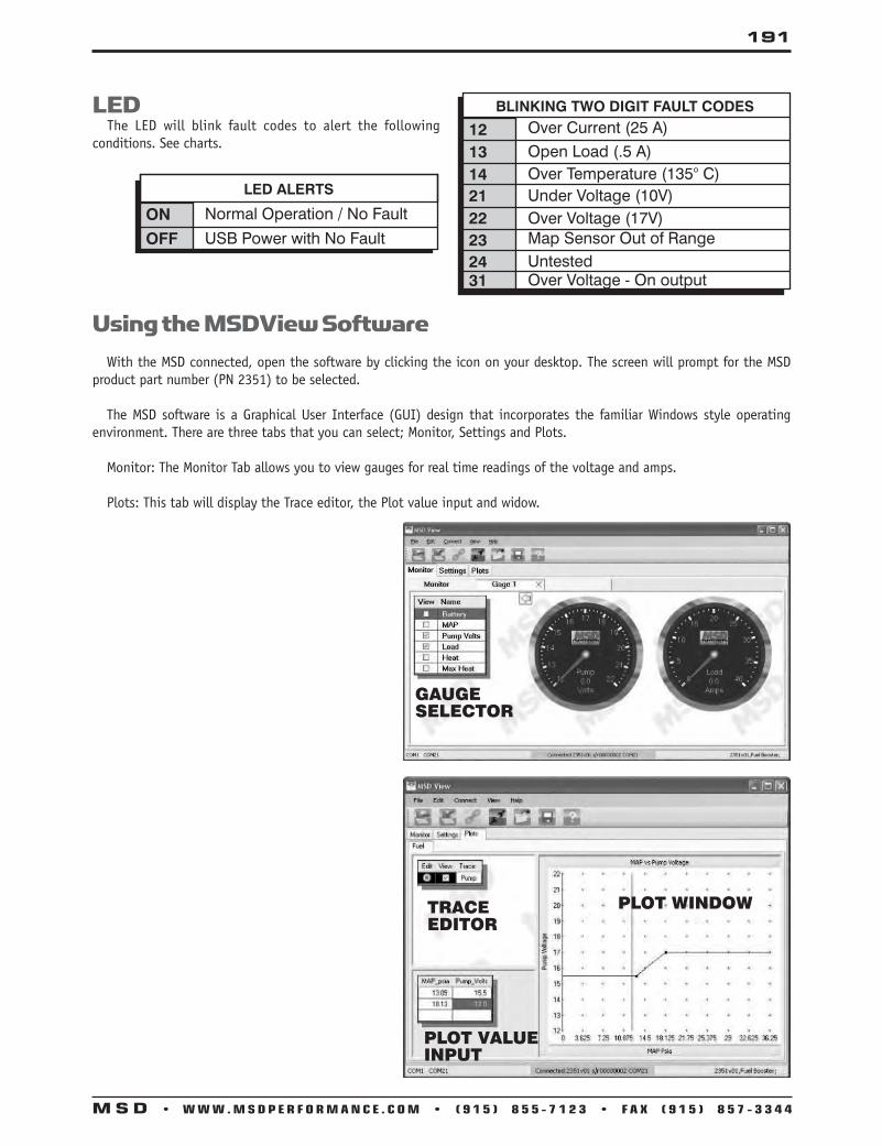
191
M S D • W W W . M S D P E R F O R M A N C E . C O M • ( 9 1 5 ) 8 5 5 - 7 1 2 3 • F A X ( 9 1 5 ) 8 5 7 - 3 3 4 4
LED The LED will blink fault codes to alert the following conditions. See charts.
ON Normal Operation / No Fault
LED ALERTS
OFF USB Power with No Fault
1213
BLINKING TWO DIGIT FAULT CODESOver Current (25 A)Open Load (.5 A)
14 Over Temperature (135° C)21222324
Under Voltage (10V)Over Voltage (17V)Map Sensor Out of RangeUntested
31 Over Voltage - On output
Using the MSDView Software With the MSD connected, open the software by clicking the icon on your desktop. The screen will prompt for the MSD product part number (PN 2351) to be selected.
The MSD software is a Graphical User Interface (GUI) design that incorporates the familiar Windows style operating environment. There are three tabs that you can select; Monitor, Settings and Plots.
Monitor: The Monitor Tab allows you to view gauges for real time readings of the voltage and amps.
Plots: This tab will display the Trace editor, the Plot value input and widow.
PLOT WINDOWTRACEEDITOR
PLOT VALUE INPUT
GAUGESELECTOR

192
M S D • W W W . M S D P E R F O R M A N C E . C O M • ( 9 1 5 ) 8 5 5 - 7 1 2 3 • F A X ( 9 1 5 ) 8 5 7 - 3 3 4 4
Ignition Tester, PN 8998 MSD’s Ignition Tester, PN 8998, will give you a quick way to confirm the operation of your MSD Ignition and Coil. It will also let you check rev limits, rpm switches and the camshaft sync signal of controls with Individual Cylinder Management circuits.
The Tester connects easily to a 12 volt source, ground and a trigger wire. The PN 8998 will simulate a trigger signal through either the points (White) wire or magnetic pickup connector of the ignition. A test plug is supplied that connects to the coil secondary wire leading to the distributor and ground. When the Tester is turned on, a spark will jump the gap of the test plug confirming operation of the Ignition and Coil.
The PN 8998 is designed for testing single channel MSD Ignitions such as the 6A, Digital-7 and even the MSD 8. It can also be used with MSD Timing Controls.
White:
Violet and Green:
Light Blue and Green:
Red:Black:
Connects to switched 12 volt source. Connects to ground.
Connects to points or an ignition amplifier input. When this wire is used the Magnetic Pickup is not (Violet and Green).These wires are routed together in one harness and form the magnetic pickup connector. This connector plugs directly into an MSD Magnetic Pickup Input. The Violet wire is positive (+) and the Green wire is negative (-). When this connector is used, the White wire is not.
General Wiring
Trigger Wires
Cam SyncThis connector is used to confirm the cam sync signal for use with Individual Cylinder Manage-ment circuit. When the engine runs, it will show “Cam Sync - Sync” for a good signal “Cam Sync - None” if there is a problem.
Cylinder Select: Push the Program Selection button on top of the PN 8998 to select 4, 6 or 8-cylinder operation.

193
M S D • W W W . M S D P E R F O R M A N C E . C O M • ( 9 1 5 ) 8 5 5 - 7 1 2 3 • F A X ( 9 1 5 ) 8 5 7 - 3 3 4 4
MSD Ignition Tester, PN 8998, to MSD 6-Series Ignition with Points
AUTOTRONIC CONTROLS CORPORATION
SERIAL NO..IGNITION
PART NO.
AUTOTRONIC CONTROLS CORPORATION
SERIAL NO..IGNITION
PART NO.
MSD Ignition Tester, PN 8998, to MSD 7-Series Ignitionwith Mag Pickup

194
M S D • W W W . M S D P E R F O R M A N C E . C O M • ( 9 1 5 ) 8 5 5 - 7 1 2 3 • F A X ( 9 1 5 ) 8 5 7 - 3 3 4 4
MSD Ignition Tester, PN 8998, to MSD 7-Series Ignitionwith Timing Control
BATTERY(+) (-)
RED
BLA
CK
BLA
CK
RED
CAMSYNC
WHITENOT USED
DISCONNECT
++ --
MAGNETICPICKUP
DISTRIBUTOR
CRANK TRIGGER
OR
TESTPLUG
CONNECTTO
GROUND
COIL WIRE
BLACK
TO 12 VOLTS
ORANGE
RED
COIL
MAGNETICPICKUP
+
MSD Ignition Tester, PN 8998, to MSD ProgrammableDigital-7 Ignition
Note: The Obsoleted PN 8995 Tester will not work through the magnetic pickup of a timing control.

195
M S D • W W W . M S D P E R F O R M A N C E . C O M • ( 9 1 5 ) 8 5 5 - 7 1 2 3 • F A X ( 9 1 5 ) 8 5 7 - 3 3 4 4
MSD Spark Plug Wires If you suspect a spark plug wire to be open, or the cause for poor engine performance, the resistance of each wire can be checked. This will tell you two things:
1. That there is continuity (plug wire is not open). 2. That there is too much resistance in the wire.
Using an Ohm Meter, connect the terminals to the spark plug wire connectors. It is a good idea to try to push the boot up, to ensure that a good contact is being made. The resistance should be: A . Heli-Core Wire: 150-1,200 ohms per foot of wire B . 8.5mm Super Conductor: 40-50 ohms, per foot of wire
NOTE: For other brand wires check with the manufacturer for their specifications.
Checking Pickups You can check the resistance of the magnetic pickup of an MSD Distributor. Using an Ohm Meter, connect the leads to the VIOLET and ORANGE wires at the two wire distributor connector. A . The resistance should be: 550 - 750 ohms. B . If the resistance is out of this specification, check all of the wiring connections. If the wires are okay, the magnetic
pickup is at fault.
8.5MM SUPER CONDUCTORWIRE (RED OR BLACK)
Troubleshooting

196
M S D • W W W . M S D P E R F O R M A N C E . C O M • ( 9 1 5 ) 8 5 5 - 7 1 2 3 • F A X ( 9 1 5 ) 8 5 7 - 3 3 4 4
If for some reason you feel that you have a non-functioning MSD Ignition Control, this simple test can be performed to determine if the MSD Ignition Control is functioning properly.
If triggering the MSD using the magnetic pickup connector (Violet and Green Wire) of the MSD:
A . Make sure the ignition switch is in the “OFF” position. B . Remove the coil wire from the distributor cap and set the wire 1/2” from ground, such as the intake manifold
or cylinder head. Do not crank or attempt to start the engine. C . Disconnect the magnetic pickup wires from the distributor or crank trigger pickup. Turn the ignition switch
to the “ON” position. Do not attempt to crank the engine. D . With a small jumper wire, short the Green and Violet magnetic pickup wire going to the MSD together several
times. Continue to step E below.
If triggering using the White wire of the MSD Series Ignition:
A . Make sure the ignition switch is in the “OFF” position. B . Remove the coil wire from the distributor cap and set the wire 1/2” from ground, such as thee intake mani-
fold or cylinder head. (Do not crank or attempt to start the engine.) C . Disconnect the MSD White wire from the distributor’s points or ignition amplifier. Turn the ignition switch
to the “ON” position. Do not attempt to crank the engine. D . Tap the White wire to ground several times. E . When the magnetic pickup wires (Violet and Green) are shorted together repeatedly or the White wire is
tapped to ground, a spark should jump from the coil wire to ground. If there is no spark substitute another coil and repeat the test. After repeating the test with another coil, if a spark still does not occur from the coil wire, remove the small “Red” wire from your MSD going to your ignition key “On/Off” source and attach it directly to the positive (+) terminal on your battery.
NOTE: Attaching the “Red” wire directly to the positive side of the battery will cause the engine not to shut off when the ignition key is turned off. If attaching the wire to the positive side of the battery cures the problem, then you must find a different “On/Off” 12 volt source for the small “Red” wire from the MSD. If after all of the above tests have been performed and no spark appears, then your box is in need of repair.
How to Test an MSD Series Ignition Control
Magnetic Pickup Trigger
White Wire Trigger
Service In case of malfunction, this MSD component will be repaired free of charge according to the terms of the warranty. When returning MSD components for warranty service, Proof of Purchase must be supplied for verification. After the warranty period has expired, repair service is based on a minimum and maximum fee. All returns must have a Return Material Authorization (RMA) number issued to them before being returned. To obtain an RMA number please contact MSD Customer Service at 1 (888) MSD-7859 or visit our website at www.msdignition.com/rma to automatically obtain a number and shipping information. When returning the unit for repair, leave all wires at the length in which you have them installed. Be sure to include a detailed account of any problems experienced, and what components and accessories are installed on the vehicle. The repaired unit will be returned as soon as possible using Ground shipping methods (ground shipping is covered by warranty). For more information, call MSD Ignition at (915) 855-7123. MSD technicians are available from 7:00 a.m. to 5:00 p.m. Monday - Friday (mountain time).

WIRING DIAGRAMS ANDTECH NOTES
INCLUDING:Wiring Diagrams
Tech TipsTroubleshooting
Operation
WWW.MSDPERFORMANCE.COM | TECH LINE (915) 855-71231490 Henry Brennan Dr. El Paso, Texas 79936 (915) 857-5200
© 2014 MSD LLCPN 9615
TECH LINE (915) 855-7123WWW.MSDPERFORMANCE.COM
MSD
WIR
ING
DIA
GR
AM
S A
ND
TECH
NO
TES
ORANGE
BLACK
MAGNETIC PICKUP(NOT USED)
GRAYTACH OUTPUT
RED
WHITE
FROM POINTS OR ELECTRONICIGNITION AMPLIFIER
(ORIGINAL COIL WIRE)
FROM IGNITION KEY(ORIGINAL COIL WIRE)
GREEN (-)VIOLET (+)
DIGITAL 6AL
REVLIMITER
RED - 12V SW OUTBLACK - BATTERY (-)
ORANGE - BATTERY 12VWHITE - POINTS OUT
MSDCAN MAG PICKUP
CONNECTOR
LEGACY IGNITION
SWITCHED IGNITION 12VGREEN - STEP 5LT. GREEN - STEP 4TAN - STEP 3VIOLET - STEP 2PINK - STEP 1
BLUE - LAUNCHLT. BLUE - BURN OUT
BRN/WHITE - RPM/TIME SWITCH
WHITE - POINTS IN
GRAY - TACHYELLOW - SHIFT LIGHT
V-NETCABLE
ECTSENSOR
PINK - FAN 2 PROVIDES GROUNDTAN - FAN 1 PROVIDES GROUND
RED - IGNITION SWITCHED 12V*
FUEL PUMP
BLACK - GROUND
HEAVY RED - BATTERY
O2SENSOR
BLACK GROUND
NOT USED (FOR TIMING CONTROL ONLY)MAG
ORANGE TO AC INPUT
YELLOW - IGNITION OUTPUT (USED WITH TIMING CONTROL ONLY)
WHITE TO MSD TACH OUTPUT
HEAVY ORANGE
*Do NOT connect the small Red wire to the coil (+) terminal when using an MSD Ignition or other CD ignition control.
RED - IGNITION SWITCHED 12V
GRAY TO TACH INPUT
INDICATES CONNECTIONTO 12V
IGNITIONKEYOR FOR STOCK
IGNITION SYSTEMS
TO NITROUS 12V ACTIVATION WIRE
cvr_2013.indd 1 1/9/2014 8:53:11 AM