Salinity Tolerances for the Major Biotic Components within the ...
JOURNAL OF LASER APPLICATIONS VOLUME 23, NUMBER 1 FEBRUARY 2011
Tolerances of joint gaps in Nd:YAG laser welded Ti-6Al-4V alloywith the addition of filler wire
X. Caoa�
Aerospace Manufacturing Technology Centre, Institute for Aerospace Research, National Research CouncilCanada, 5145 Decelles Ave., Montreal, Quebec H3T 2B2, Canada
G. DebaeckerEcole Centrale de Nantes, 1 Rue de la Noé, B.P. 92101, 44321 Nantes Cedex 3, France
E. PoirierAerospace Manufacturing Technology Centre, Institute for Aerospace Research, National Research CouncilCanada, 5145 Decelles Ave., Montreal, Quebec H3T 2B2, Canada
S. MaryaEcole Centrale de Nantes, 1 Rue de la Noé, B.P. 92101, 44321 Nantes Cedex 3, France
J. Cuddy and A. BirurStandard Aero Limited, 33 Allen Dyne Road, Winnipeg, Manitoba R3H 1A1, Canada
P. WanjaraAerospace Manufacturing Technology Centre, Institute for Aerospace Research, National Research CouncilCanada, 5145 Decelles Ave., Montreal, Quebec H3T 2B2, Canada
�Received 18 November 2009; accepted for publication 17 January 2011;published 23 February 2011�
The effect of joint gap on the butt joint quality of Ti-6Al-4V alloy welded using a 4 kW Nd:yttriumaluminum garnet laser was evaluated in terms of the welding defects, microstructure, hardness, andtensile properties. The joint gap was proportionally filled using the filler wire with the compositionsof the parent alloy. Fully penetrated welds without cracking were obtained up to a joint gap of 0.5mm. The main defects observed in the welds were porosity and underfill. Specifically, the porosityarea increased with increasing joint gap but remained less than 1% of the fusion zone area. Largeunderfill defects appeared in the weldments in the absence of a joint gap, but filler wire addition wasobserved to reduce this defect in the presence of a joint gap. The weld hardness decreased slightlywith increasing joint gap, but the tensile properties were optimized at an intermediary gap size,probably due to the compromise between the low underfill �after the use of a filler wire� and alimited amount of porosity. © 2011 Laser Institute of America.
Key words: laser welding, titanium alloy, joint gap, filler wire
I. INTRODUCTION
The high temperature performance, low density, biocom-patibility, and excellent corrosion-resistance of titanium andits alloys have led to a wide range of applications in demand-ing service conditions for the aerospace, automotive, medi-cal, power generation, oil and gas extraction, chemical plant,and sporting industries. Ti-6Al-4V, a workhorse grade thataccounts for more than half of all the titanium tonnage in theworld,1 is a two-phase �+� titanium alloy which containsaluminum as the alpha stabilizer and vanadium as the betastabilizer. Due to its high strength-to-weight ratio, along withgood tensile and creep properties up to a service temperatureof 300 °C, Ti-6Al-4V has been successfully used for diverseapplications including �1� medical, dental, and surgical de-vices; �2� turbine disks, compressor blades, and rings for jetengines; �3� airframe and space capsule components; �4�
a�
Electronic mail: [email protected]1042-346X/2011/23�1�/012004/10/$28.00 012004
pressure vessels; �5� rocket engine casings; �6� helicopterrotor hubs; and �7� critical structural forgings.2
Conventionally, gas tungsten-arc, gas metal-arc, plasmaarc welding, and electron beam welding have been used toweld titanium alloys.3–5 To date, the laser welding of Ti-6Al-4V has mainly concentrated on using CO2 lasers.1,5–7
Limited work has been reported about the weldability of Ti-6Al-4V using high power continuous wave �CW� solid-stateNd:yttrium aluminum garnet �YAG� and fiber lasers.8,9 Laserwelding has many advantages including low and precise heatinput, deep and narrow fusion zone �FZ�, small heat-affectedzone �HAZ�, low thermal distortion, high productivity, andgood process flexibility and reliability. However, since thespot size of the laser beam and the associated molten poolare relatively small, laser welding processes in general havea low tolerance for seam gaps.10 Therefore, there is an exi-gent challenge for workshop practice to achieve precise jointpreparation, workpiece clamping, and manipulator accuracy,
which can reduce the cost-effectiveness of manufacturing.© 2011 Laser Institute of America-1
012004-2 J. Laser Appl., Vol. 23, No. 1, February 2011 Cao et al.
Clearly, an increased gap tolerance can potentially increaseproductivity and improve the process stability and joint qual-ity in an industrial environment.
Recently, Aalderink et al.10 compared some laser-basedwelding techniques for their gap bridging capabilities for1–2-mm-thick AA5182 aluminum alloy sheets. It was foundthat the use of the filler wire is indispensable to increase thegap tolerance. For the single spot laser welding with the useof the cold filler wire, a gap up to 0.6 mm can be bridged asopposed to a maximum allowable gap of 0.2 mm without theuse of the filler wire. However, Sun and Kuo11 investigatedbridging ability of CO2 laser welding for carbon and stain-less steels. It was found that a large gap of up to 1.0 mm for2.0-mm-thick butt joint was successfully welded with the useof a filler wire. The maximum joint gap accommodated isalmost equal to the diameter of the filler wire. In spite of theinconsistency in the reported gap tolerances, as a rule ofthumb, the allowable joint gap is around 10% of the work-piece thickness.11 For example, a joint gap of 0.3 mm is themaximum allowable gap to produce a satisfactory joint for3-mm-thick sheets.
To further improve the bridging capacities, laser-arc hy-brid welding process has been widely investigated. It wasreported that the laser-arc hybrid welding process can bridgea gap up to 1.0 mm.10 Yao et al.12 even reported that laser-archybrid welding process is rather insensitive to a joint gapbelow 3 mm as long as the arc parameters are set highenough to bridge these gaps. In laser-arc hybrid welding, thefiller wire is required to ignite/maintain arc and compensatefor the lack of metal in a relatively large joint gap. The fillerwire can be melted by partial consumption of the laser en-ergy or auxiliary electric arc, or by both.13 In the hybridprocess, laser generates a deeper melt, while the arc suppliesthe molten filler metal to the weld pool. Although laser-archybrid process has been successfully implemented in shipbuilding, transport, and construction industry,14 its applica-tion requires more elaborate tuning of multiple process pa-rameters related to arc as well as to laser.15 In addition, thelaser-arc interactions can also help to stabilize the arc, par-ticularly at high welding speeds.16
Compared with the laser alone welding process, laser-archybrid technique demonstrated significant advantages for itsgap bridging capacities. However, laser alone process is rela-tively simple and hence is still preferred for aerospace appli-cations. To date, limited work has been carried out for aero-space titanium alloys using a high power laser. In addition, asystematic investigation on the effect of the joint gap on thequality of aerospace titanium welds is still lacking. This isessential to provide practical technical guidelines for aero-space industry. To this end, the tolerance of the joint gap for3-mm-thick Ti-6Al-4V alloy was systematically studied us-ing a 4 kW CW Nd:YAG laser with a beam size of approxi-mately 0.45 mm. The joint quality is characterized in termsof dimensions, porosity, underfill, microstructure, hardness,and tensile properties.
II. EXPERIMENTAL PROCEDURES
As-received mill-annealed grade 5 Ti-6Al-4V sheets
�AMS 4911� were sectioned into coupons with dimensions ofthe roughly 102 mm in length�63 mm in width�3.05 mm in thickness. Laser welding was performedalong the specimen length, which was perpendicular to therolling direction of the sheet material. The faying and adja-cent surfaces of each specimen were brushed and thencleaned with ethanol to remove any contaminants prior tofixturing. The welding equipment consisted of a 4 kW CWsolid-state Nd:YAG laser system equipped with an ABB ro-bot and a magnetic holding fixture. A collimation lens of 200mm, a focal lens of 150 mm, and a fiber diameter of 0.6 mmwere employed to produce a laser beam with a focusing spotdiameter of approximately 0.45 mm and a Rayleigh length of2.34 mm. Since titanium is highly reactive with atmosphericelements, especially in the liquid state and at high tempera-tures, adequate measures were taken to shield the fusion zoneand the heated surfaces until these regions were cooled be-low 100 °C. In this work, high purity argon at a flow rate of23.6 l/min �50 cfh� was used to shield the top surface of theworkpieces. The shielding of the root and the trailing gasshield on the top surface were performed using helium at atotal flow rate of 66.1 l/min �140 cfh�. All experiments werecarried out at a laser power of 4.0 kW, a defocusing distanceof �1 mm �i.e., 1 mm below the sheet top surface� and awelding speed of 3.0 m/min. The joint gap used was variedfrom 0 �no gap� to 0.6 mm �Table I�. A Ti-6Al-4V filler wire�AMS 4956A ELI� with a nominal diameter of 1.14 mm wasfed at a fixed angle of 30° toward the top surface of theworkpiece. It is noteworthy that the filler wire was usuallyimpinged by the laser beam on the top surface of the work-piece. The feed rate of the filler wire was calculated by usingthe volume flow rate constancy equation
Wire feed rate =Welding speed � Gap area
Filler wire area.
Selected joints were then examined for defects using x-rays.The surface quality of the laser welds was visually evaluatedin the as-welded condition. Three transverse sections werecut from each weld to examine the weld integrity and micro-structure using optical microscopy. After sectioning, thespecimens were mounted using cold-setting resin, groundand polished using automated techniques to produce a mir-rorlike finish. Etching of specimens was performed by im-mersion in Kroll’s reagent �1–3 ml HF+2–6 ml HNO3
+100 ml H2O� for 10–25 s. Microstructural examination
TABLE I. Welding processing parameters used.a
Trial No.Joint gap
�mm�Wire feed rate
�m/min� X-ray examination
1 0 0 Not examined2 0.1 0.9 Three voids3 0.2 1.8 One void4 0.3 2.7 Four voids5 0.4 3.6 Five voids6 0.5 4.5 Two voids7 0.6 5.4 Not examined
aNote: Pore size ranges from 0.25 to 0.5 mm.
was carried out using an inverted optical microscope �Olym-

012004-3J. Laser Appl., Vol. 23, No. 1, February 2011 Cao et al.
pus GX710�, equipped with a digital camera and ANALYSIS
FIVE image analysis software for measurement of the jointgeometry. The microstructure was also observed for selectedspecimens using a Hitachi S-3600N scanning electron micro-scope �SEM� with an EDAX Genesis energy dispersive x-rayspectroscopy �EDS� system. The Vickers microindentationhardness was performed using a Struers Duramin A-300hardness tester at a load of 500 g, a dwell period of 15 s, andan interval of 0.2 mm. Also for each joint, four subsize ten-sile specimens were machined according to ASTM E8M-01to give gauge dimensions of 6.0 mm in width, 32 mm inparallel length, and 125 mm in overall length. The specimenswere tested at room temperature using a 50 kN Instron ma-chine, a 2620-604 Instron extensometer �gauge length of 25mm used�, and a crosshead speed of 2 mm/min.
III. RESULTS AND DISCUSSION
A. Joint geometry
Visual inspection of the welds revealed a silver metallicsurface indicating that good shielding during welding wasachieved. Figure 1 shows the overview of the transversesections obtained at various joint gaps. It can be seen thatthe welds are fully penetrated for joint gap values up to 0.5mm, i.e., the maximum gap tolerance was determined to be0.5 mm, roughly equivalent to the beam size used. At 0.6mm, a lack-of-penetration defect appears. The differentareas, i.e., FZ, HAZ, and base metal �BM�, can be clearlydistinguished due to the microstructural differences acrossthe welds.
As shown in Fig. 2, the area and width of the FZ �top,middle, and bottom� decrease with increasing joint gap. This
(a) 0 mm (b) 0.1 mm
(c) 0.2 mm (d) 0.3 mm
(e) 0.4 mm (f) 0.5 mm
(g) 0.6 mm (h) 0.6 mm
1 mm 1 mm
1 mm 1 mm
1 mm 1 mm
1 mm 1 mm
FIG. 1. Overview of weld cross sections at various gaps.
decrease is more prominent at a small joint gap and then
becomes relatively smooth above a gap size of 0.2 mm. It isnoteworthy that in Fig. 2 the values at a joint gap of 0.6 mmare not taken into account due to the lack-of-penetrationdefect for this condition. In this latter case, a zero root widthis assumed. Similarly, the HAZ area and width also decreasewith increasing joint gap. For the middle HAZ width, thereis an erratic value at a gap of 0.6 mm. This is due to theformation of the lack-of-penetration defect. In this case, theentire molten metal is located on the upper part of the weld,and the width is therefore increased �Figs. 1�g� and 1�h��.
The overall decrease in the dimensions of the FZ andHAZ at higher joint gap values is directly linked to theincrease in the gap size. The laser beam was set to bealigned with the joint in between the two workpieces to bebutt welded. Hence, in the presence of a gap �between 0.1
(a)
(b)
(c)
0
2
4
6
8
10
0,0 0,2 0,4 0,6Joint gap (mm)
Are
a(m
m²)
HAZFZ
0
1
2
3
4
5
0,0 0,2 0,4 0,6
Joint gap (mm)
Fusi
onzo
new
idth
(mm
)
TopMiddleRoot
0,0
0,5
1,0
1,5
0,0 0,2 0,4 0,6Joint gap (mm)
HA
Zm
id-w
idth
(mm
)
LOP
FIG. 2. Effect of gap on FZ and HAZ area and width.
and 0.6 mm in this work�, part of the laser beam can be
012004-4 J. Laser Appl., Vol. 23, No. 1, February 2011 Cao et al.
directly lost through the gap. In addition, laser energy maybe lost due to the reflection caused by the filler wire surface.These losses of the laser energy increase obviously withincreasing joint spacing and wire feed rate. Less effectiveenergy available for welding leads to smaller FZ and HAZ.In addition, significant variations in the penetration depth areobserved at a joint gap of 0.6 mm indicating the instabilityof laser energy absorption at a large joint gap �Figs. 1�g� and1�h��.
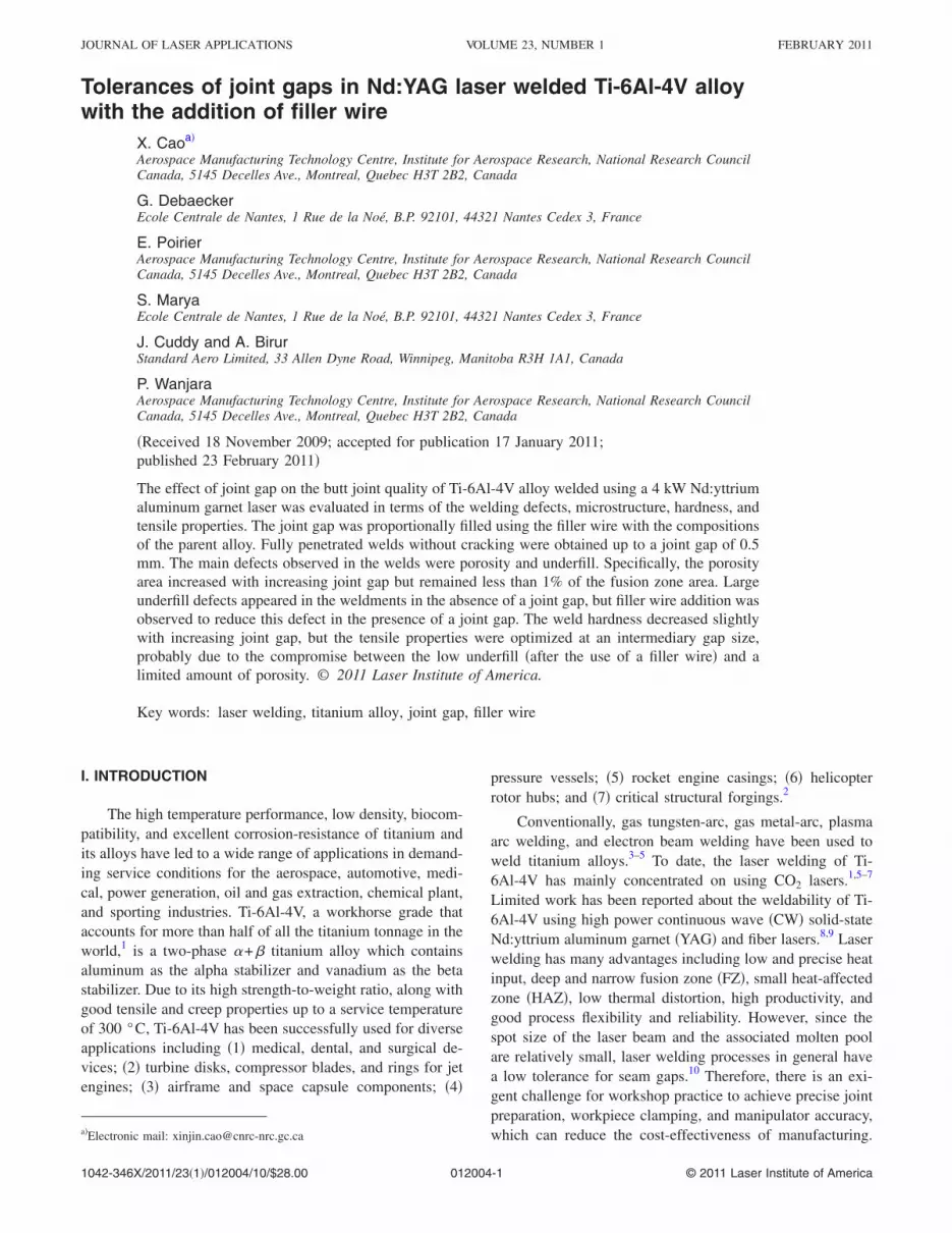
As shown in Figs. 3�a� and 3�c�, the joint gap has noclear influence on the weld reinforcement area and height.Generally speaking, the reinforcement height remainsrelatively low, 0.2–0.25 mm �less than 10% of the sheetthickness�, for most of the fully penetrated joints and meets
0.0
0.1
0.2
0.3
0.0 0.2 0.4 0.6
Joint gap (mm)
Are
a(m
m²)
Underfil areaReinforcement area
(a)
0,0
0,1
0,2
0,3
0,0 0,2 0,4 0,6Joint gap (mm)
Unde
rfilld
epth
(mm
)
Max. underfill depthAverage underfill depth
(b)
0,0
0,1
0,2
0,3
0,4
0,5
0,0 0,2 0,4 0,6Joint gap (mm)
Rein
forc
emen
thei
ght(
mm
)
Average heightMax. height
(c)
FIG. 3. Effect of joint gap on underfill and reinforcement area and size.
the acceptance criteria stipulated in AWSD17.
B. Welding defects
As shown in Fig. 1, no cracks are observed in theweldment, but porosity frequently appeared in the FZ. Thiswas further confirmed by X-ray examination and analysis asindicated in Table I. In this study, the minimum dimensionsthat can be detected by X-ray were approximately 0.025 mmfor the porosity and 0.025�0.127 mm2 for linearindications �cracks, lack of fusion, etc.�. In addition,underfill defects are visible on both the crown and root sidesof the welds, as shown in Fig. 1. However as indicated inFig. 3�b�, the overall underfill depth for gap sizes from 0.1 to0.5 mm is less than 0.12 for the fully penetrated joints andmeets the acceptance criteria stipulated in AWSD17.
C. Underfill defects
Large underfill defects are observed on both the crownand root sides of the welds in the absence of a joint gap. Asis well known, underfill defects can weaken welds. Forexample, underfilling can reduce the sheet thickness andcreate stress concentration that will significantly reduce thetensile and fatigue strengths of the joints. Underfill defects,therefore, must be minimized. Specifically, the area anddepth of the underfill defect on both the crown and root sidesof the welds were measured as given in Fig. 3. It can benoticed that the average or maximum underfill depth appearsat zero joint gap, namely, without the use of a filler wire.Compared with the zero joint gap, the average or maximumunderfill depth is approximately halved at gap values from0.1 to 0.5 mm. This trend is further intensified for theunderfill area. The total underfill area including that on boththe top and bottom sides obtained with zero gap wasapproximately five times greater than that at gap sizes from0.1 to 0.5 mm. Therefore, the application of filler wire canincrease the gap tolerance, reduce the underfill defects, andimprove the process stability while saving both preparationtime and costs for welding.
At zero joint gap, the overall underfill area is almost fivetimes the reinforcement area indicating a significant loss ofthe molten metal, probably due to a combination of moltenmetal spattering and evaporation. When a filler metal wasused, the loss of molten metal was significantly decreased.The measurement of the alloy chemistry using EDS with aSEM indicated a composition of 6.4 wt % Al and 3.0 wt %V for the base metal and 6.5 wt % Al and 2.6 wt % V for theFZ, which suggests that the evaporative losses from themolten weld pool are minor during laser welding. However,the reinforcement area was greater than the underfill area, atjoint gaps from 0.1 to 0.5 mm �Fig. 3�a��, which may berelated to combined effects of thermal expansion and phasetransformation.
D. Porosity defects
In addition to the underfill defects discussed above,porosity is another main defect that was frequently observed,as shown in Fig. 1. Most of the porosity is nearly sphericalin shapes but some are elongated. The pores can appear at
various locations, depending on their origin. They are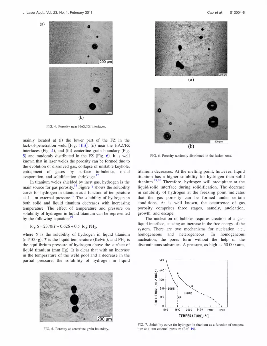
012004-5J. Laser Appl., Vol. 23, No. 1, February 2011 Cao et al.
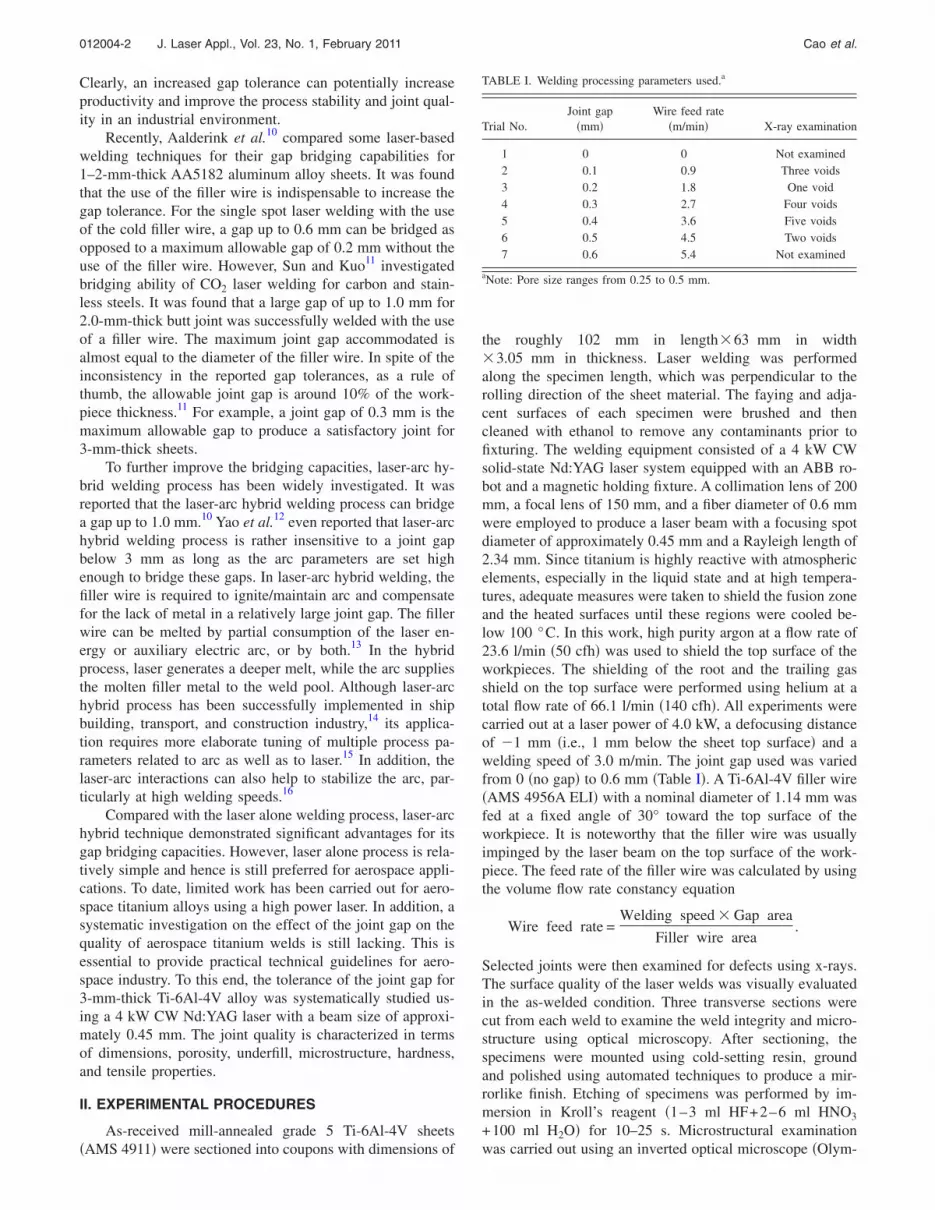
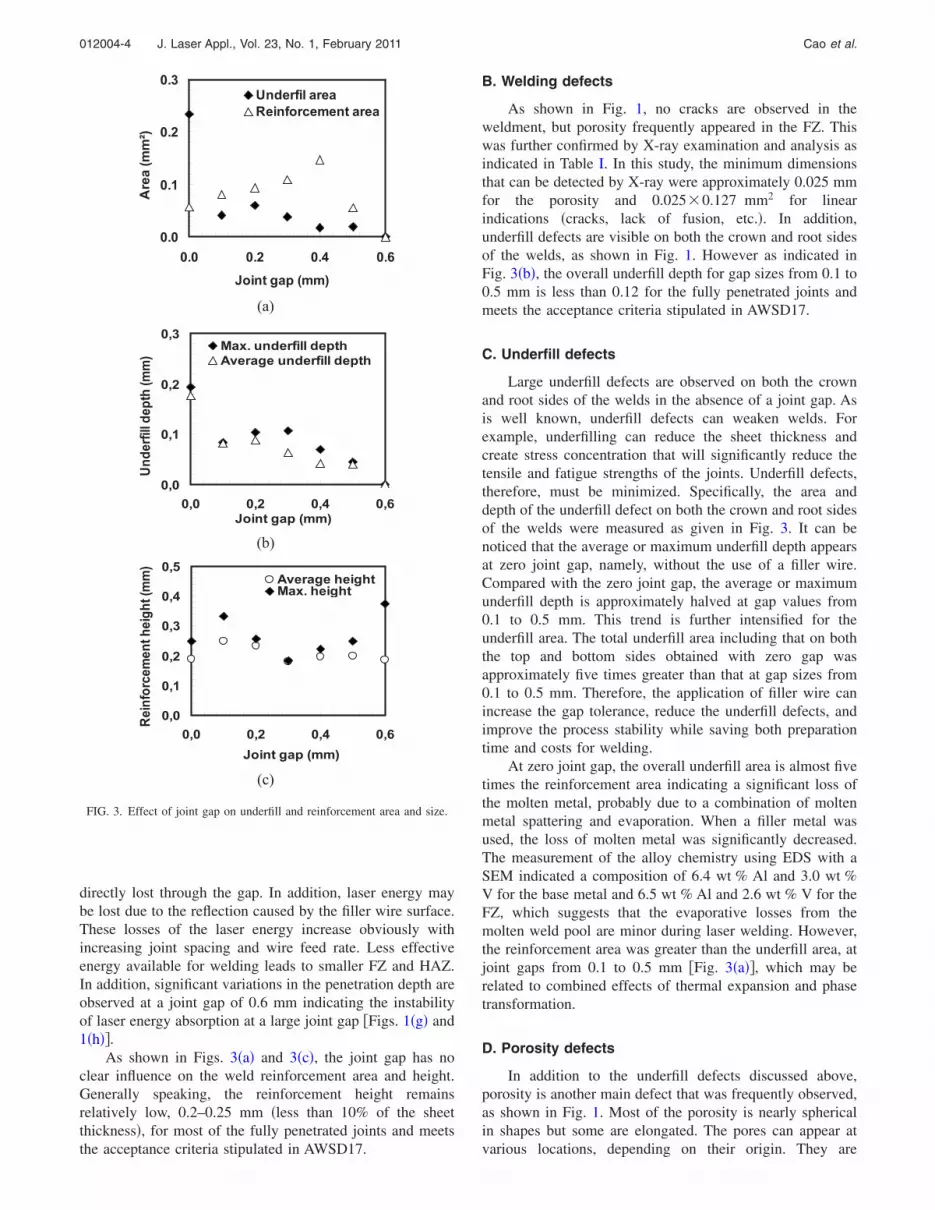
mainly located at �i� the lower part of the FZ in thelack-of-penetration weld �Fig. 1�h��, �ii� near the HAZ/FZinterfaces �Fig. 4�, and �iii� centerline grain boundary �Fig.5� and randomly distributed in the FZ �Fig. 6�. It is wellknown that in laser welds the porosity can be formed due tothe evolution of dissolved gas, collapse of unstable keyhole,entrapment of gases by surface turbulence, metalevaporation, and solidification shrinkage.17
In titanium welds shielded by inert gas, hydrogen is themain source for gas porosity.18 Figure 7 shows the solubilitycurve for hydrogen in titanium as a function of temperatureat 1 atm external pressure.19 The solubility of hydrogen inboth solid and liquid titanium decreases with increasingtemperature. The effect of temperature and pressure onsolubility of hydrogen in liquid titanium can be representedby the following equation:19
log S = 2370/T + 0.626 + 0.5 log PH2,
where S is the solubility of hydrogen in liquid titanium�ml/100 g�, T is the liquid temperature �Kelvin�, and PH2 isthe equilibrium pressure of hydrogen above the surface ofliquid titanium �mm Hg�. It is clear that with an increasein the temperature of the weld pool and a decrease in thepartial pressure, the solubility of hydrogen in liquid
(a)
(b)
FIG. 4. Porosity near HAZ/FZ interfaces.
FIG. 5. Porosity at centerline grain boundary.
titanium decreases. At the melting point, however, liquidtitanium has a higher solubility for hydrogen than solidtitanium.19,20 Therefore, hydrogen will precipitate at theliquid/solid interface during solidification. The decreasein solubility of hydrogen at the freezing point indicatesthat the gas porosity can be formed under certainconditions. As is well known, the occurrence of gasporosity comprises three stages, namely, nucleation,growth, and escape.
The nucleation of bubbles requires creation of a gas-liquid interface, causing an increase in the free energy of thesystem. There are two mechanisms for nucleation, i.e.,homogeneous and heterogeneous. In homogeneousnucleation, the pores form without the help of thediscontinuous substrates. A pressure, as high as 50 000 atm,
(a)
(b)
FIG. 6. Porosity randomly distributed in the fusion zone.
FIG. 7. Solubility curve for hydrogen in titanium as a function of tempera-
ture at 1 atm external pressure �Ref. 19�.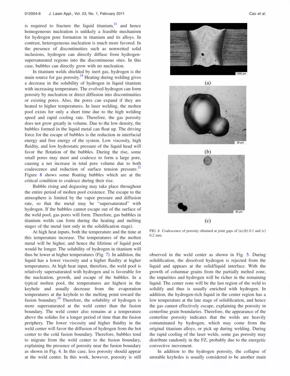
012004-6 J. Laser Appl., Vol. 23, No. 1, February 2011 Cao et al.
is required to fracture the liquid titanium,21 and hencehomogeneous nucleation is unlikely a feasible mechanismfor hydrogen pore formation in titanium and its alloys. Incontrast, heterogeneous nucleation is much more favored. Inthe presence of discontinuities such as nonwetted solidinclusions, hydrogen can directly diffuse from hydrogen-supersaturated regions into the discontinuous sites. In thiscase, bubbles can directly grow with no nucleation.
In titanium welds shielded by inert gas, hydrogen is themain source for gas porosity.18 Heating during welding givesa decrease in the solubility of hydrogen in liquid titaniumwith increasing temperature. The evolved hydrogen can formporosity by nucleation or direct diffusion into discontinuitiesor existing pores. Also, the pores can expand if they areheated to higher temperatures. In laser welding, the moltenpool exists for only a short time due to the high weldingspeed and rapid cooling rate. Therefore, the gas porositydoes not grow greatly in volume. Due to the low density, thebubbles formed in the liquid metal can float up. The drivingforce for the escape of bubbles is the reduction in interfacialenergy and free energy of the system. Low viscosity, highfluidity, and low hydrostatic pressure of the liquid head willfavor the flotation of the bubbles. During the rise, somesmall pores may meet and coalesce to form a large pore,causing a net increase in total pore volume due to bothcoalescence and reduction of surface tension pressure.21
Figure 8 shows some floating bubbles which are at thecritical condition to coalesce during their rise.
Bubble rising and degassing may take place throughoutthe entire period of molten pool existence. The escape to theatmosphere is limited by the vapor pressure and diffusionrate, so that the metal may be “supersaturated” withhydrogen. If the bubbles cannot escape out of the surface ofthe weld pool, gas pores will form. Therefore, gas bubbles intitanium welds can form during the heating and meltingstages of the metal �not only in the solidification stage�.
At high heat inputs, both the temperature and the time atthis temperature increase. The temperatures of the moltenmetal will be higher, and hence the lifetime of liquid poolwould be longer. The solubility of hydrogen in titanium willthus be lower at higher temperatures �Fig. 7�. In addition, theliquid has a lower viscosity and a higher fluidity at highertemperatures. At high heat input, therefore, the weld pool isrelatively supersaturated with hydrogen and is favorable forthe nucleation, growth, and escape of the bubbles. In atypical molten pool, the temperatures are highest in thekeyhole and usually decrease from the evaporationtemperatures at the keyhole to the melting point toward thefusion boundary.19 Therefore, the solubility of hydrogen ismore supersaturated at the weld center than the fusionboundary. The weld center also remains at a temperatureabove the solidus for a longer period of time than the fusionperiphery. The lower viscosity and higher fluidity in theweld center will favor the diffusion of hydrogen from the hotcenter to the cold fusion boundary. Therefore, bubbles tendto migrate from the weld center to the fusion boundary,explaining the presence of porosity near the fusion boundaryas shown in Fig. 4. In this case, less porosity should appear
at the weld center. In this work, however, porosity is stillobserved in the weld center as shown in Fig. 5. Duringsolidification, the dissolved hydrogen is rejected from theliquid and appears at the solid/liquid interface. With thegrowth of columnar grains from the partially melted zone,the impurities and hydrogen will be richer in the remainingliquid. The center zone will be the last region of the weld tosolidify and thus is usually enriched with hydrogen. Inaddition, the hydrogen-rich liquid in the center region has alow temperature at the late stage of solidification, and hencethe gas cannot effectively escape, explaining the porosity incenterline grain boundaries. Therefore, the appearance of thecenterline porosity indicates that the welds are heavilycontaminated by hydrogen, which may come from theoriginal titanium alloys, or pick up during welding. Duringthe rapid cooling of the laser welds, some gas porosity maydistribute randomly in the FZ, probably due to the energeticconvective movement.
In addition to the hydrogen porosity, the collapse of
(a)
(b)
(c)
FIG. 8. Coalescence of porosity obtained at joint gaps of �a�,�b� 0.1 and �c�0.2 mm.
unstable keyholes is usually considered to be another main
012004-7J. Laser Appl., Vol. 23, No. 1, February 2011 Cao et al.
mechanism for the formation of porosity in laser welds.17
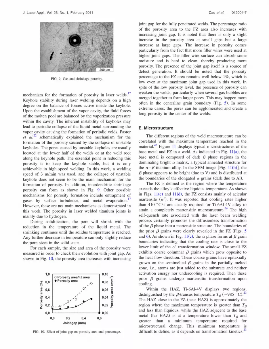
Keyhole stability during laser welding depends on a highdegree on the balance of forces active inside the keyhole.Upon the establishment of the vapor cavity, the fluid forcesof the molten pool are balanced by the vaporization pressurewithin the cavity. The inherent instability of keyholes maylead to periodic collapse of the liquid metal surrounding thevapor cavity causing the formation of periodic voids. Pastoret al.22 schematically explained the mechanism for theformation of the porosity caused by the collapse of unstablekeyholes. The pores caused by unstable keyholes are usuallylocated at the lower half of the welds or at the weld rootalong the keyhole path. The essential point in reducing thisporosity is to keep the keyhole stable, but it is onlyachievable in high speed welding. In this work, a weldingspeed of 3 m/min was used, and the collapse of unstablekeyhole does not seem to be the main mechanism for theformation of porosity. In addition, interdendritic shrinkageporosity can form as shown in Fig. 9. Other possiblemechanisms for porosity formation include entrapment ofgases by surface turbulence, and metal evaporation.17
However, these are not main mechanisms as demonstrated inthis work. The porosity in laser welded titanium joints ismainly due to hydrogen.
During solidification, the pore will shrink with thereduction in the temperature of the liquid metal. Theshrinking continues until the solidus temperature is reached.Any further decrease in temperature can only slightly reducethe pore sizes in the solid state.
For each sample, the size and area of the porosity weremeasured in order to check their evolution with joint gap. Asshown in Fig. 10, the porosity area increases with increasing
FIG. 9. Gas and shrinkage porosity.
0,0
0,2
0,4
0,6
0,8
1,0
0,0 0,2 0,4 0,6Joint gap (mm)
Por
osity
area
(%)
0,00
0,02
0,04
0,06
0,08
0,10
Por
osity
area
(mm
2 )Porosity area/FZ areaPorosity area
FIG. 10. Effect of joint gap on porosity area and percentage.
joint gap for the fully penetrated welds. The percentage ratioof the porosity area to the FZ area also increases withincreasing joint gap. It is noted that there is only a slightincrease in the porosity area at small gaps but a largeincrease at large gaps. The increase in porosity comesparticularly from the fact that more filler wires were used athigher joint gaps. The filler wire surface can absorb somemoisture and is hard to clean, thereby producing moreporosity. The presence of the joint gap itself is a source ofdefect generation. It should be noted that the porositypercentage to the FZ area remains well below 1%, which islow even at the maximum joint gap used in this work. Inspite of the low porosity level, the presence of porosity canweaken the welds, particularly when several gas bubbles aremerged together to form larger pores. This may happen moreoften in the centerline grain boundary �Fig. 5�. In someextreme cases, the pores can be agglomerated and create along porosity in the center of the welds.
E. Microstructure
The different regions of the weld macrostructure can becorrelated with the maximum temperature reached in thematerial.23 Figure 11 displays typical microstructures of thebase metal and FZ in a weld. As indicated in Fig. 11�a�, thebase metal is composed of dark � phase regions in thedominating bright � matrix, a typical annealed structure forthe �−� titanium alloy. In the SEM image �Fig. 11�b��, the� phase appears to be bright �due to V� and is distributed atthe boundaries of the elongated � grains �dark due to Al�.
The FZ is defined as the region where the temperatureexceeds the alloy’s effective liquidus temperature. As shownin Figs. 11�c� and 11�d�, the FZ consists mainly of acicularmartensite ����. It was reported that cooling rates higherthan 410 °C /s are usually required for Ti-6Al-4V alloy toattain a completely martensitic microstructure.24 The highself-quench rate associated with the laser beam weldingprocess certainly promotes the diffusionless transformationof the � phase into a martensitic structure. The boundaries ofthe prior � grains were clearly revealed in the FZ �Figs. 5and 6�. As shown in Fig. 11�c�, the � phase forms at � grainboundaries indicating that the cooling rate is close to thelower limit of the �� transformation window. The small FZexhibits coarse columnar � grains which grow opposite tothe heat flow direction. These coarse grains have epitaxiallygrown on the semimelted � grains in the partially meltedzone, i.e., atoms are just added to the substrate and neitheractivation energy nor undercooling is required. Then theseprior � grains undergo martensitic transformation uponcooling.
Within the HAZ, Ti-6Al-4V displays two regions,distinguished by the �-transus temperature T� ��985 °C�.23
The HAZ close to the FZ �near HAZ� is approximately theregion where the maximum temperature is greater than T�
and less than liquidus, while the HAZ adjacent to the basemetal �far HAZ� is at a temperature lower than T� andgreater than a minimum temperature required formicrostructural change. This minimum temperature is
23
difficult to define, as it depends on transformation kinetics.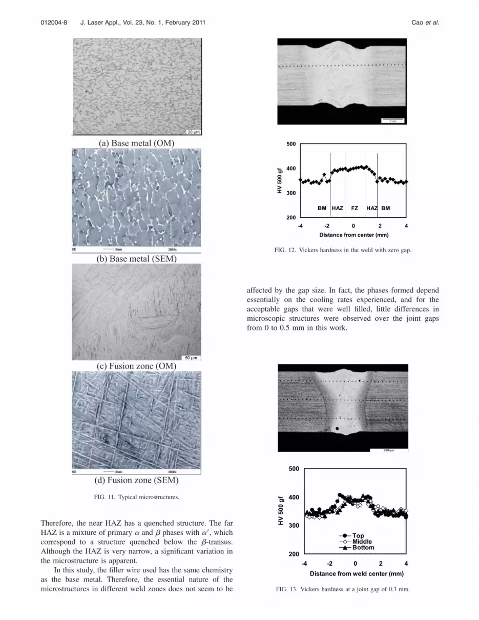
012004-8 J. Laser Appl., Vol. 23, No. 1, February 2011 Cao et al.
Therefore, the near HAZ has a quenched structure. The farHAZ is a mixture of primary � and � phases with ��, whichcorrespond to a structure quenched below the �-transus.Although the HAZ is very narrow, a significant variation inthe microstructure is apparent.
In this study, the filler wire used has the same chemistryas the base metal. Therefore, the essential nature of the
.(a) Base metal (OM)
(b) Base metal (SEM)
(c) Fusion zone (OM)
(d) Fusion zone (SEM)
FIG. 11. Typical microstructures.
microstructures in different weld zones does not seem to be
affected by the gap size. In fact, the phases formed dependessentially on the cooling rates experienced, and for theacceptable gaps that were well filled, little differences inmicroscopic structures were observed over the joint gapsfrom 0 to 0.5 mm in this work.
200
300
400
500
-4 -2 0 2 4Distance from center (mm)
HV50
0gf
FZ HAZHAZ BMBM
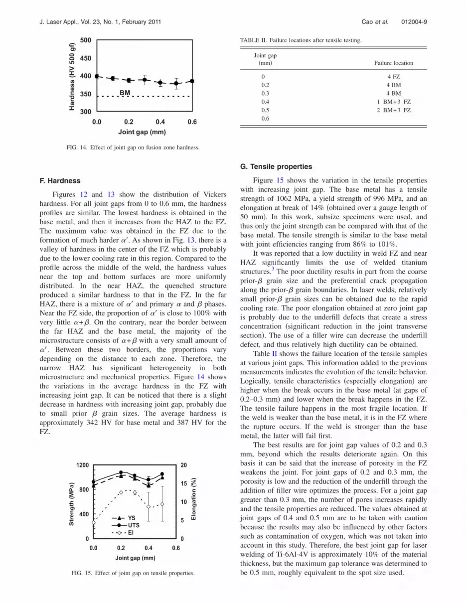
FIG. 12. Vickers hardness in the weld with zero gap.
200
300
400
500
-4 -2 0 2 4Distance from weld center (mm)
HV50
0gf
TopMiddleBottom
FIG. 13. Vickers hardness at a joint gap of 0.3 mm.
012004-9J. Laser Appl., Vol. 23, No. 1, February 2011 Cao et al.
F. Hardness
Figures 12 and 13 show the distribution of Vickershardness. For all joint gaps from 0 to 0.6 mm, the hardnessprofiles are similar. The lowest hardness is obtained in thebase metal, and then it increases from the HAZ to the FZ.The maximum value was obtained in the FZ due to theformation of much harder ��. As shown in Fig. 13, there is avalley of hardness in the center of the FZ which is probablydue to the lower cooling rate in this region. Compared to theprofile across the middle of the weld, the hardness valuesnear the top and bottom surfaces are more uniformlydistributed. In the near HAZ, the quenched structureproduced a similar hardness to that in the FZ. In the farHAZ, there is a mixture of �� and primary � and � phases.Near the FZ side, the proportion of �� is close to 100% withvery little �+�. On the contrary, near the border betweenthe far HAZ and the base metal, the majority of themicrostructure consists of �+� with a very small amount of��. Between these two borders, the proportions varydepending on the distance to each zone. Therefore, thenarrow HAZ has significant heterogeneity in bothmicrostructure and mechanical properties. Figure 14 showsthe variations in the average hardness in the FZ withincreasing joint gap. It can be noticed that there is a slightdecrease in hardness with increasing joint gap, probably dueto small prior � grain sizes. The average hardness isapproximately 342 HV for base metal and 387 HV for theFZ.
0
400
800
1200
0.0 0.2 0.4 0.6Joint gap (mm)
Strength(MPa)
0
5
10
15
20
Elongation(%)
YSUTSEl
300
350
400
450
500
0.0 0.2 0.4 0.6Joint gap (mm)
Hardn
ess(HV50
0gf)
BM
FIG. 14. Effect of joint gap on fusion zone hardness.
FIG. 15. Effect of joint gap on tensile properties.
G. Tensile properties
Figure 15 shows the variation in the tensile propertieswith increasing joint gap. The base metal has a tensilestrength of 1062 MPa, a yield strength of 996 MPa, and anelongation at break of 14% �obtained over a gauge length of50 mm�. In this work, subsize specimens were used, andthus only the joint strength can be compared with that of thebase metal. The tensile strength is similar to the base metalwith joint efficiencies ranging from 86% to 101%.
It was reported that a low ductility in weld FZ and nearHAZ significantly limits the use of welded titaniumstructures.3 The poor ductility results in part from the coarseprior-� grain size and the preferential crack propagationalong the prior-� grain boundaries. In laser welds, relativelysmall prior-� grain sizes can be obtained due to the rapidcooling rate. The poor elongation obtained at zero joint gapis probably due to the underfill defects that create a stressconcentration �significant reduction in the joint transversesection�. The use of a filler wire can decrease the underfilldefect, and thus relatively high ductility can be obtained.
Table II shows the failure location of the tensile samplesat various joint gaps. This information added to the previousmeasurements indicates the evolution of the tensile behavior.Logically, tensile characteristics �especially elongation� arehigher when the break occurs in the base metal �at gaps of0.2–0.3 mm� and lower when the break happens in the FZ.The tensile failure happens in the most fragile location. Ifthe weld is weaker than the base metal, it is in the FZ wherethe rupture occurs. If the weld is stronger than the basemetal, the latter will fail first.
The best results are for joint gap values of 0.2 and 0.3mm, beyond which the results deteriorate again. On thisbasis it can be said that the increase of porosity in the FZweakens the joint. For joint gaps of 0.2 and 0.3 mm, theporosity is low and the reduction of the underfill through theaddition of filler wire optimizes the process. For a joint gapgreater than 0.3 mm, the number of pores increases rapidlyand the tensile properties are reduced. The values obtained atjoint gaps of 0.4 and 0.5 mm are to be taken with cautionbecause the results may also be influenced by other factorssuch as contamination of oxygen, which was not taken intoaccount in this study. Therefore, the best joint gap for laserwelding of Ti-6Al-4V is approximately 10% of the materialthickness, but the maximum gap tolerance was determined to
TABLE II. Failure locations after tensile testing.
Joint gap�mm� Failure location
0 4 FZ0.2 4 BM0.3 4 BM0.4 1 BM+3 FZ0.5 2 BM+3 FZ0.6
be 0.5 mm, roughly equivalent to the spot size used.

012004-10 J. Laser Appl., Vol. 23, No. 1, February 2011 Cao et al.
IV. CONCLUSIONS
�1� When the filler wire with the compositions of the parentalloy is used, the butt joints can be welded with a fullpenetration up to a joint gap of 0.5 mm, roughly equiva-lent to the spot size used.
�2� The dimensions of the fusion and heat-affected zonesare reduced with increasing joint gap.
�3� No cracks were detected in the laser welds. The maindefects observed are underfill and gas porosity. The porearea increases with increasing joint gap but remains lessthan 1% of the FZ area. The underfill defect is moreprominent in the absence of a joint gap, and the use of afiller wire can significantly reduce this defect.
�4� The hardness of the welds is slightly decreased withincreasing joint gap. The welds have good resistance forall gap sizes with a joint efficiency ranging from 86% to101%. But the optimal tensile properties are obtained atan intermediary joint gap �0.2–0.3 mm�, approximately10% of the material thickness, which provides a balancebetween the low underfill, due to the use of a filler wire,and a limited amount of porosity.
ACKNOWLEDGMENTS
Thanks are due to B. Marius for the technical supportprovided during tensile property testing.
1G. Casalino, F. Curcio, and F. M. C. Minutolo, “Investigation on Ti-6Al-4V laser welding using statistical and Taguchi approaches,” J. Mater.Process. Technol. 167, 422–428 �2005�.
2“Technical data sheet: Allvac titanium 6Al-4V alloy,” http://www.allvac.com.
3W. A. Baeslack III, D. W. Becker, and F. H. Froes, “Advances in titaniumalloy welding metallurgy,” J. Met. 5, 46–58 �1984�.
4L. W. Tsay and C. Y. Tsay, “The effect of microstructures on the fatiguecrack growth in Ti-6Al-4V laser welds,” Int. J. Fatigue 19, 713–720�1997�.
5Z. Sun, D. Pan, and W. Zhang, Proceedings of the 6th International Con-ference: Trends in Welding Research, Pine Mountain, GA, 2002 �unpub-lished�, pp. 760–767.
6F. Caiazzo, F. Curcio, G. Daurelio, and F. M. C. Minutolo, “Ti-6Al-4Vsheets lap and butt joints carried out by CO2 laser: Mechanical and mor-phological characterization,” J. Mater. Process. Technol. 149, 546–552�2004�.
7
F. Memola, C. Minutolo, F. Curcio, G. Daurelio, and F. Caiazzo, Proceed-ings of XV International Symposium on Gas Flow, Chemical Lasers, andHigh-Power Lasers, Bellingham, WA, 2005, edited by J. Kodymova �un-published�, pp. 907–912.
8X. Cao and M. Jahazi, “Effect of welding speed on butt joint quality ofTi-6Al-4V alloy welded using a high power Nd:YAG laser,” Opt. LasersEng. 47, 1231–1241 �2009�.
9X. Cao, G. Debaecker, M. Jahazi, S. Marya, J. Cuddy, and A. Birur,“Effect of post-weld heat treatment on Nd:YAG laser welded Ti-6Al-4Valloy quality,” Mater. Sci. Forum 638–642, 3655–3660 �2010�.
10B. J. Aalderink, B. Pathirajand, and R. G. K. M. Aarts, “Seam gap bridg-ing of laser based processes for the welding of aluminum sheets for in-dustrial applications,” Int. J. Adv. Manuf. Technol. 48, 143–154 �2010�.
11Z. Sun and M. Kuo, “Bridging the joint gap with wire feed laser weld-ing,” J. Mater. Process. Technol. 87, 213–222 �1999�.
12Y. Yao, M. Wouters, K. Nilsson, and A. F. H. Kaplan, “Influence of jointgeometry and fit-up gaps on hybrid laser-metal active gas �MAG� weld-ing,” J. Laser Appl. 18, 283–288 �2006�.
13J. K. Kristensen, D. Petring, and S. Webster, Proceedings of the 63rdAnnual Assembly & International Conference of International Institute ofWelding, AWST-10/101, July 2010 �unpublished�, pp. 507–515.
14S. Keitel, U. Jsanu, and J. Neubert, Fourth International Symposium onHigh Power Lasers and Their Applications, St. Petersburg, Russia, 24–26June 2008 �unpublished�.
15S. Katayama, Hybrid-Laser Arc Welding, edited by O. O. Flemming�Woodhead, Cambridge, UK, 2009�, pp. 28–46.
16P. E. Denney, B. W. Shinn, and P. M. Fallara, Proceedings of the 15thInternational Offshore and Polar Engineering Conference, Seoul, Korea,19–24 June 2005 �The International Society of Offshore and Polar Engi-neers, CA, 2005�, p. 106.
17X. Cao, M. Jahazi, J. P. Immarigeon, and W. Wallace, “A review of laserwelding techniques for magnesium alloys,” J. Mater. Process. Technol.171, 188–204 �2006�.
18G. L. Petrov and A. N. Khatuntsev, “The role of chemical reactions in theformation of pores in the welding of titanium alloys,” Svar. Proiz. 8,81–84 �1975�.
19T. Mohandas, D. Banerjee, and V. V. Kutumba Rao, “Fusion zone micro-structure and porosity in electron beam welds of an �+� titanium alloy,”Metall. Mater. Trans. A 30A, 789–798 �1999�.
20D. R. Mitchell, “Porosity in titanium welds,” Welding Supplement 4,157s–167s �1965�.
21F. Karimzadeh, M. Salehi, A. Saatchi, and M. Meratian, “Effect of mi-croplasma arc welding process parameters on grain growth and porositydistribution of thin sheet Ti6Al4V alloy weldment,” Mater. Manuf. Pro-cesses 20, 205–219 �2005�.
22M. Pastor, H. Zhao, and T. DebRoy, “Pore formation during continuouswave Nd:YAG laser welding of aluminum for automotive applications,”Revista de Metalurgia 36, 108–117 �2000�.
23A. B. Short, “Gas tungsten arc welding of �+� titanium alloys: A re-view,” Mater. Sci. Technol. 25, 309–324 �2009�.
24T. Ahmed and H. J. Rack, “Phase transformation during cooling in �
+� titanium alloys,” Mater. Sci. Eng., A 243, 206–211 �1998�.Copyright © 2022 FDOKUMEN