XPS and EIS study of the passive film formed on orthopaedic Ti–6Al–7Nb alloy in Hank's...
12
Available online at www.sciencedirect.com Electrochimica Acta 53 (2008) 3547–3558 XPS and EIS study of the passive film formed on orthopaedic Ti–6Al–7Nb alloy in Hank’s physiological solution I. Miloˇ sev a,b,∗ , T. Kosec a , H.-H. Strehblow c a J. Stefan Institute, Jamova cesta 39, 1000 Ljubljana, Slovenia b Orthopaedic Hospital Valdoltra, Jadranska c. 31, 6280 Ankaran, Slovenia c Institut of Physical Chemistry, Heinrich Heine University, Universit¨ atsstr. 1, D-40225 D¨ usseldorf, Germany Received 4 December 2007; received in revised form 11 December 2007; accepted 15 December 2007 Available online 23 December 2007 Abstract The composition and structure of the passive film formed on Ti–6Al–7Nb alloy by electrochemical oxidation in Hank’s physiological solution were studied using X-ray photoelectron spectroscopy (XPS) and electrochemical impedance spectroscopy (EIS). The oxide layer was predominantly TiO 2 , but contained small amounts of suboxides TiO and Ti 2 O 3 at potentials more negative than 0.75 V. At more positive potentials, TiO 2 was the only form. The formation of suboxides in the lower potential range is less pronounced than in Ti–6Al–4V alloy. The passive range in Hank’s physiological solution is broad and extends up to 6.0V. Aluminium oxide Al 2 O 3 , and niobium oxides, Nb 2 O 5 , and NbO and/or NbO 2 , are incorporated in the passive layer. Angular resolved XPS analysis confirmed that they are located mainly at the outer oxide/solution interface of the TiO 2 matrix. The thickness of the oxide layer was dependent on the oxidation potential and, after oxidation at 5.75 V, it reached 9.4 nm. EIS measurements correlate well with the XPS data. The incorporation of the oxides of alloying elements into the TiO 2 layer is reflected in the increase in the outer layer resistance at high anodic potentials and longer immersion times. The consequences of this process are beneficial for the overall stability and high corrosion resistance of the Ti–6Al–7Nb alloy under physiological conditions. © 2007 Elsevier Ltd. All rights reserved. Keywords: Ti alloy; Ti6Al7Nb; Electrochemical oxidation; Hank’s physiological solution; XPS; EIS 1. Introduction Titanium alloys are today one of the most important metallic materials used in orthopaedics and dental surgery. Despite their high corrosion resistance in the physiological environment, the finding at revision surgery of damage at the metal surface and consequent periprosthetic metallosis indicates that failures of the implant occur in vivo. In vivo degradation of metallic bio- materials due to combined wear and corrosion processes results in the formation of particulate and ionic metallic debris, which are recognized as major factors limiting the lifespan of joint replacements [1]. Release of wear debris has both local and sys- temic consequences. Locally, the biological response consists of synovitis and periprosthetic bone loss, which lead to aseptic loosening. Systemic dissemination of metal debris leads to sys- ∗ Corresponding author at: Department of Physical and Organic Chemistry, J. Stefan Institute, Jamova cesta 39, 1000 Ljubljana, Slovenia. Tel.: +386 1 4773 452; fax: +386 1 4773 822. E-mail address: [email protected] (I. Miloˇ sev). temic increase of metal levels in body fluids and accumulation in distant organs [2]. In the case of titanium, it has been reported that levels of Ti are greater in patients with failed total knee and hip replacements [3,4] than in controls or in patients with stable prostheses. Although there was no detectable systemic increase in the levels of Al and V [3–5], particulate debris isolated from the periprosthetic tissue [6] and from distant organs [2] con- tained these elements. In vivo [7,8] and in vitro [9] studies have provided evidence that an immunological response is induced by titanium-based wear debris. Hallab et al. reported that V is toxic in vitro at concentrations below those in synovial fluid in vivo [10]. The administration of metallic ions, using metal- lic powders, to fibroblast L929 and osteoblast MC3T3-E1 cells showed that Ti, Zr, Sn, Nb and Ta had no effect on their relative growth ratios. Al and V ions, however, exhibited cytotoxicity at concentrations ≥0.2 ppm [11]. In the light of these observations, further investigation of titanium alloys is increasingly important for gaining a better understanding of traditionally used alloys, and for helping in the search for new titanium alloys. Because of the possible risks associated with vanadium, Semlitsch devel- 0013-4686/$ – see front matter © 2007 Elsevier Ltd. All rights reserved. doi:10.1016/j.electacta.2007.12.041
Transcript of XPS and EIS study of the passive film formed on orthopaedic Ti–6Al–7Nb alloy in Hank's...

A
wTfsptwrc©
K
1
mhfictmiartol
ST
0d
Available online at www.sciencedirect.com
Electrochimica Acta 53 (2008) 3547–3558
XPS and EIS study of the passive film formed on orthopaedicTi–6Al–7Nb alloy in Hank’s physiological solution
I. Milosev a,b,∗, T. Kosec a, H.-H. Strehblow c
a J. Stefan Institute, Jamova cesta 39, 1000 Ljubljana, Sloveniab Orthopaedic Hospital Valdoltra, Jadranska c. 31, 6280 Ankaran, Slovenia
c Institut of Physical Chemistry, Heinrich Heine University, Universitatsstr. 1, D-40225 Dusseldorf, Germany
Received 4 December 2007; received in revised form 11 December 2007; accepted 15 December 2007Available online 23 December 2007
bstract
The composition and structure of the passive film formed on Ti–6Al–7Nb alloy by electrochemical oxidation in Hank’s physiological solutionere studied using X-ray photoelectron spectroscopy (XPS) and electrochemical impedance spectroscopy (EIS). The oxide layer was predominantlyiO2, but contained small amounts of suboxides TiO and Ti2O3 at potentials more negative than 0.75 V. At more positive potentials, TiO2 was the onlyorm. The formation of suboxides in the lower potential range is less pronounced than in Ti–6Al–4V alloy. The passive range in Hank’s physiologicalolution is broad and extends up to 6.0 V. Aluminium oxide Al2O3, and niobium oxides, Nb2O5, and NbO and/or NbO2, are incorporated in theassive layer. Angular resolved XPS analysis confirmed that they are located mainly at the outer oxide/solution interface of the TiO2 matrix. The
hickness of the oxide layer was dependent on the oxidation potential and, after oxidation at 5.75 V, it reached 9.4 nm. EIS measurements correlateell with the XPS data. The incorporation of the oxides of alloying elements into the TiO2 layer is reflected in the increase in the outer layeresistance at high anodic potentials and longer immersion times. The consequences of this process are beneficial for the overall stability and highorrosion resistance of the Ti–6Al–7Nb alloy under physiological conditions.
2007 Elsevier Ltd. All rights reserved.
al sol
tithpittpbti
eywords: Ti alloy; Ti6Al7Nb; Electrochemical oxidation; Hank’s physiologic
. Introduction
Titanium alloys are today one of the most important metallicaterials used in orthopaedics and dental surgery. Despite their
igh corrosion resistance in the physiological environment, thending at revision surgery of damage at the metal surface andonsequent periprosthetic metallosis indicates that failures ofhe implant occur in vivo. In vivo degradation of metallic bio-
aterials due to combined wear and corrosion processes resultsn the formation of particulate and ionic metallic debris, whichre recognized as major factors limiting the lifespan of jointeplacements [1]. Release of wear debris has both local and sys-
emic consequences. Locally, the biological response consistsf synovitis and periprosthetic bone loss, which lead to asepticoosening. Systemic dissemination of metal debris leads to sys-∗ Corresponding author at: Department of Physical and Organic Chemistry, J.tefan Institute, Jamova cesta 39, 1000 Ljubljana, Slovenia.el.: +386 1 4773 452; fax: +386 1 4773 822.
E-mail address: [email protected] (I. Milosev).
lsgcffao
013-4686/$ – see front matter © 2007 Elsevier Ltd. All rights reserved.oi:10.1016/j.electacta.2007.12.041
ution; XPS; EIS
emic increase of metal levels in body fluids and accumulationn distant organs [2]. In the case of titanium, it has been reportedhat levels of Ti are greater in patients with failed total knee andip replacements [3,4] than in controls or in patients with stablerostheses. Although there was no detectable systemic increasen the levels of Al and V [3–5], particulate debris isolated fromhe periprosthetic tissue [6] and from distant organs [2] con-ained these elements. In vivo [7,8] and in vitro [9] studies haverovided evidence that an immunological response is inducedy titanium-based wear debris. Hallab et al. reported that V isoxic in vitro at concentrations below those in synovial fluidn vivo [10]. The administration of metallic ions, using metal-ic powders, to fibroblast L929 and osteoblast MC3T3-E1 cellshowed that Ti, Zr, Sn, Nb and Ta had no effect on their relativerowth ratios. Al and V ions, however, exhibited cytotoxicity atoncentrations ≥0.2 ppm [11]. In the light of these observations,
urther investigation of titanium alloys is increasingly importantor gaining a better understanding of traditionally used alloys,nd for helping in the search for new titanium alloys. Becausef the possible risks associated with vanadium, Semlitsch devel-
3 mica
owclmm
arlCtsts[Naaomsfl
dstanpb[efns1Oo
tpeadcoasCtaost[w
it
alrteipwb
efgT[�TTTiTTwT[abu
nb[ht
[ticoXio
2
uiW
548 I. Milosev et al. / Electrochi
ped the alternative alloy, Ti–6Al–7Nb, in which the vanadiumas exchanged for niobium [12]. Today this alloy is the preferred
hoice for cementless total joint replacements [13]. Immuno-ogical studies have provided evidence that exposure of human
onocytes to TiAlNb particles results in smaller release of cellediators than does equivalent exposure to TiAlV particles [14].Corrosion stability is a prerequisite for in vivo applications,
nd the electrochemical properties and consequent corrosionesistance of Ti and Ti-based alloys under simulated physio-ogical conditions have been the subject of numerous reports.omparison of published data is sometimes difficult due to
he different experimental parameters used. Electrochemicaltudies have been carried out in Hank’s physiological solu-ion [15,16], EDTA-containing Hanks’s solution [17], Ringerolution [18–22], 0.9% NaCl [23], phosphate-buffered saline24–26] and a simulated physiological solution based on 0.14 MaCl [27,28]. Besides these chloride-based solutions, various
dditives and other simulated body fluids have been tested inttempts to closely simulate the body fluids, such as the additionf lactate and acetate [27], amino acids [19], bovine serum albu-in [25], Eagle’s minimal essential medium [24], calf serum
olution [24,25], bovine serum [29] and serum, urine and jointuids from patients [30].
There is a general agreement that the passive layer formeduring electrochemical studies in chloride-based media with-tands exposure to physiological chloride solution at bodyemperature. The superior corrosion resistance has beenttributed to the semiconducting properties of the oxide film,amely to a lower density of electron donors [27]. The com-osition of the oxide layer was identified as rutile-type TiO2y XPS [17,22,24,31], AES [17,19,31] and electron diffraction18]. Whereas the presence of Al2O3 in the passive layer is wellstablished, the identification of V-oxide has not been so straight-orward [17,24]. Sundararajan et al. observed oxidized Al, butot oxidized V in the layer [19,22]. Lee observed V after 700 s ofputtering of the oxide layer formed on Ti–6Al–4V alloy afterday exposure to EDTA-containing Hank’s solution [17,24].n the other hand, Okazaki et al. observed a small amount ofxidized V [24].
The adsorption of Ca2+ and PO43− ions to the surface of
he TiO2 formed on Ti–6Al–4V and Ti–6Al7–Nb alloys takeslace within the first hour of exposure to a simulated biologicalnvironment at 37 ◦C [28]. Albumin has been reported to inter-ct with the repassivation process of the surface of Ti alloysue to the change in charge resulting from their zwitterionharacter [25]. As the pH increases, the corrosion resistancef Ti-based alloys also increased, which was ascribed to thedsorption of a metal/protein/hydroxide complex at the metalurface, which restricts the dissolution of metal [25]. Similarly,ontu et al. observed higher polarization resistance in serum
han in sodium sulphate solution [29]. This observation wasscribed to the adsorbed layer of proteins that both hinderedxygen evolution and the charge transfer responsible for dis-
olution of the passive film. The most relevant experiments inerms of physiological applications were performed by Hsu et al.30]. The corrosion resistance of Ti–6Al–4V alloy in joint fluidas found to be significantly lower than in serum or urine, whichtems
Acta 53 (2008) 3547–3558
s obviously related to various compositions of biological mediaested.
The behaviour of pure titanium [32–37] and of other Ti-basedlloys [15–21,23–29] has been studied under simulated physio-ogical conditions. Ti–6Al–7Nb alloy exhibits a broader passiveange than Ti–6Al–4V alloy in simulated physiological solu-ion [16,23]. Based on EIS measurements, Metikos-Hukovict al. proposed that the corrosion resistance increases due toncorporation of Nb cations into the TiO2 matrix [16]. The highrotectiveness of the passive layer formed on Ti–6Al–7Nb alloyas ascribed to formation of a double oxide layer, a dense innerarrier layer and a porous outer layer [21,38].
In order to avoid the possibility of V release and toxplore further materials with suitable mechanical propertiesor biomedical applications, numerous alloys have been investi-ated: Ti–10Mo [20], Ti–10Mo–10Al [20], Ti–7Al–4.5V [20],i–5Al–4.5V [20,39], Ti–5Al–2.5Fe [18,20,40], Ti–6Al–4Fe39,40], near � alloys such as Ti–13Nb–13Zr [26,41–44],-rich alloy Ti–5Al–3Mo–4Zr [18], and other alloys likei–50Zr [43,44], Ti–15Zr–4Nb–4Ta [45,46], Ti–6Al–4Nb [40],i–45Nb [44] and Ti–15Zr–4Nb [42]. Of the V-free alloys,i–5Al–2.5Fe was found to be superior to Ti–5Al–3Mo–4Zr
n terms of corrosion resistance in Ringer solution [18].he passivation behaviour of Ti–6Al–4Nb, Ti–6Al–4Fe andi–5Al–2.5Fe alloys in Hank’s solution was comparableith that of Ti–6Al–4V [40]. An alloy without Al or V,i–15Zr–4Nb–4Ta–0.2Pd, exhibited high corrosion resistance11]. Yu et al. demonstrated that addition of Zr or Nb (Ti–45Nbnd Ti–50Zr alloys) results in strong covalent bond formationetween neighbouring Ti, Nb and Zr atoms, through sharing ofnpaired d level electrons [44].
Surface of biocompatible alloys used as implants play sig-ificant role in their osseointegration. Various processes haveeen tested in order to increase this property, i.e. sol–gel method47,48], anodic oxidation [49], ion implantation [50], diffusionardening [51], etc. The review of the related literature is beyondhe scope of the present paper.
Despite numerous studies performed on Ti–6Al–7Nb alloy16,21,23,25,26,28,29,41,42] none was devoted to investigatinghe composition of the passive film formed in simulated phys-ological solutions. In our previous study we investigated theomposition and electronic properties of the oxide film formedn the Ti–6Al–4V alloy in Hank’s physiological solution, using-ray photoelectron spectroscopy (XPS) and electrochemical
mpedance spectroscopy (EIS) [15]. We now present the resultsf a comparable study on the Ti–6Al–7Nb alloy.
. Experimental
The methodology of the present study is the same as thatsed in our previous study on Ti–6Al–4V [15]. The test spec-mens were cut from commercial Ti–6Al–7Nb alloy (Sulzer,
interthur, Switzerland). For electrochemical measurements
he test specimens were in the form of discs (15 mm diam-ter, 2 mm thick). Specimens were polished mechanically toirror finish and rinsed with distilled water and acetone. Thepecimen was embedded in a Teflon holder, with a surface of

mica
0twaP
i0C1
awaePti6oso1iiwud
sptXAa[6ipcatpwfproDaw(ssre(
mλ
λ
te3ρ
3
3a
adsAdTtofptETsiTsialic state. As this air-formed oxide layer was sputtered away, theTi signal shifted towards a lower binding energy correspondingto metallic titanium. The presence of high amount of suboxidesof Ti and Nb in the air-formed passive film is at first surprising,
Table 1Peak parameters of the standard spectra used for evaluating the oxidizedTi–6Al–7Nb samples
Species Peak Eb (eV) FWHM (eV)
Ti Ti 2p3/2 454.0–454.2 1.7–1.8TiO Ti 2p3/2 455.4–455.8 2.3–2.4Ti2O3 Ti 2p3/2 457.2–457.6 2.3–2.4TiO2 Ti 2p3/2 459.0–459.2 1.3–1.4
Al Al 2p3/2 71.0–71.5 1.2–1.3Al2O3 Al 2p3/2 74.2–74.8 2.1–2.3
Nb Nb 3d5/2 203.0–203.5 2.0–2.1NbO/NbO2 Nb 3d5/2 204.5–204.8 1.3–1.4Nb2O5 Nb 3d5/2 207.0–207.5 1.4–1.5
O2− O 1s 530.1–530.2 1.5–1.8
I. Milosev et al. / Electrochi
.785 cm2 exposed to the solution. Potentials in the text refer tohe SCE scale. Potentiodynamic electrochemical measurementsere carried out using a scan rate of 20 mV s−1 by means ofPAR&EGG Model 263 potentiostat/galvanostat controlled byower Suite electrochemical software.
Measurements were performed at 37 ◦C in s Hank’s phys-ological solution (8 g/l NaCl, 0.4 g/l KCl, 0.35 g/l NaHCO3,.25 g/l NaH2PO4 × H2O, 0.06 g/l Na2HPO4 × 2H2O, 0.19 g/laCl2 × 2H2O, 0.19 g/l MgCl2, 0.06 g/l MgSO4 × 7H2O andg/l glucose, pH 7.8).
For electrochemical impedance spectroscopy measurementsn Autolab three-electrode corrosion cell was used, with theorking electrode embedded in a Teflon holder, exposing an
rea of 0.785 cm2. An Ag/AgCl electrode served as a refer-nce electrode and two stainless steel rods as counter electrodes.otentials were measured using an Autolab PGSTAT12 poten-
iostat/galvanostat, expanded with an FRA2 module. Potentialsn the text refer to the SCE scale. The frequency ranged from5 kHz to 5 MHz at 10 cycles per decade, with an ac amplitudef ±10 mV. The absolute impedance and phase angle were mea-ured at each frequency. Impedance measurements were carriedut at open circuit potential (OCP) and at potentials of 0.25,.0, 2.0, 2.75, 3.0 and 4.5 V vs. SCE after 1 h, 3 h and 7 h ofmmersion in the electrolyte. All measurements were conductedn Hank’s physiological solution at 37 ◦C. The impedance dataere interpreted on the basis of equivalent electrical circuits,sing the Zview (Scribner) program for fitting the experimentalata.
Electrochemical oxidation of Ti–6Al–7Nb alloy for sub-equent analysis by X-ray photoelectron spectroscopy waserformed in an electrochemical preparation chamber attachedo the ultra high vacuum spectrometer (an ESCALAB 200-
spectrometer (VG Instruments) using non-monochromatizedl K� radiation (1486.6 eV) from a twin Mg/Al anode oper-
ting at 300 W). Details of this equipment are as published15,52]. The take-off angle (Θ) was varied between 0◦ and0◦ off-normal in steps of 10◦. After immersing the samplen physiological solution under open circuit conditions, theotential was stepped to the value of interest and potentiostati-ally kept constant for 300 s. XPS was evaluated quantitativelys described [15]. The XPS spectra were background sub-racted using the non-linear, iterative Shirley method [53] androcessed by a least squares trial and error procedure [54]ith mixed Gaussian/Lorentzian peaks. The spectra recorded
or electrochemically oxidized samples were evaluated usingarameters of standard peaks (Table 1). Standard peaks wereecorded for metal samples thermally oxidized for 1 h in anxygen atmosphere at 450 ◦C (Ti), and 350 ◦C (Al and Nb).uring deconvolution of spectra recorded for electrochemically
nd air-oxidized samples, all peak parameters, except height,ere kept constant. Border conditions were also kept constant
Table 1). Ti-suboxides and NbO/NbO2 oxides were fitted usingynthetic spectra obtained as the difference between standard
pectra recorded for thermally oxidized samples and spectraecorded for electrochemically oxidized samples. The param-ters for metal peaks were recorded on sputter-cleaned samplesno oxide present).OH
Ep
Acta 53 (2008) 3547–3558 3549
The following values were used for the calculations: inelasticean free electron path: λ(Ti) = 1.73 nm, λ(TiO2) = 3.08 nm,(Al) = 2.03 nm, λ(Al2O3) = 3.61 nm, λ(Nb) = 1.93 nm,(Nb2O5) = 3.43 nm and λ(O) = 2.97 nm [55]; Scofield pho-
oionization cross sections [56] corrected according to Reilmant al. [57]: σ(Ti 2p3/2) = 4.70, σ(Al 2p3/2) = 0.50, σ(Nbd5/2) = 4.45 and σ(O 1s) = 2.51; density: ρ(TiAlV) = 4.5 and(TiO2) = 4.25 g/cm3 [58].
. Results and discussion
.1. Composition and related spectra of the spontaneouslyir-formed layer on Ti–6Al–Nb alloy
The passive layer formed spontaneously on the Ti–6Al–4Vlloy consisted of an approximately 5 nm thick layer of pre-ominantly TiO2 oxide [15]. The concentrations of titaniumuboxides were greatest at the metal/oxide interface, and ofl2O3 on top of the TiO2 layer. No oxidized vanadium wasetected. The spontaneously air-formed passive layer on thei–6Al–7Nb alloy was, at 6.5 nm, somewhat thicker, and con-
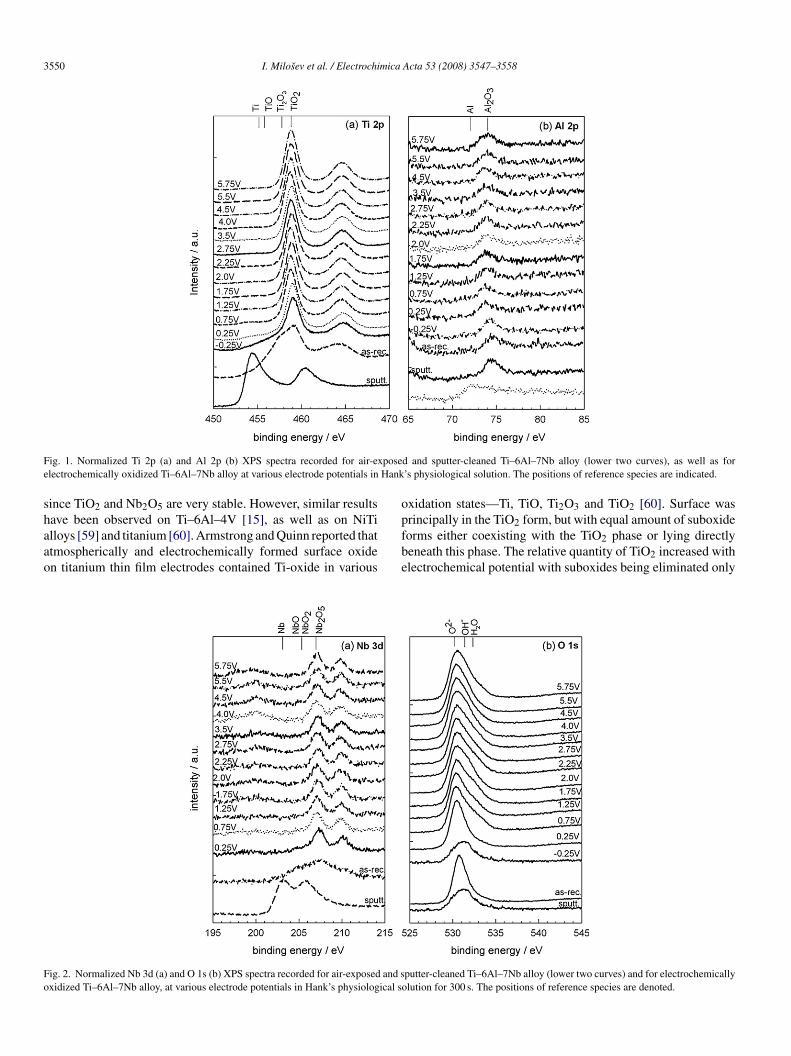
ained, niobium oxides as well as titanium and aluminiumxides. The XPS Ti 2p, Al 2p, Nb 3d and O 1s spectra recordedor air-exposed and sputter-cleaned Ti–6Al–7Nb samples areresented in Figs. 1 and 2. For an air-exposed sample the cen-re of the Ti 2p3/2 peak was located at a binding energy ofb = 459.2 eV, which denotes the presence of TiO2 [15] (Fig. 1a).he spectra of the air-formed layer could not be accounted forolely by the standard peaks for Ti and TiO2. The differencen experimental spectra was described using synthetic peaks foriO and Ti2O3 (Table 1). Quantification of the deconvolutedpectrum of the air-formed layer signal confirmed that the major-ty (45%) of the titanium was in the form of Ti2O3 (Ti3+), 34%s TiO2 (Ti4+), 8% as TiO (Ti2+) and the rest (13%) in the metal-
H− O 1s 531.4–531.5 1.5–1.8
2O O 1s 532.5–532.7 1.5–1.8
b: binding energy of the peak centre; FWHM: full width at the half height ofeak maximum.
3550 I. Milosev et al. / Electrochimica Acta 53 (2008) 3547–3558
F posee Hank
shaao
o
Fo
ig. 1. Normalized Ti 2p (a) and Al 2p (b) XPS spectra recorded for air-exlectrochemically oxidized Ti–6Al–7Nb alloy at various electrode potentials in
ince TiO2 and Nb2O5 are very stable. However, similar results
ave been observed on Ti–6Al–4V [15], as well as on NiTilloys [59] and titanium [60]. Armstrong and Quinn reported thattmospherically and electrochemically formed surface oxiden titanium thin film electrodes contained Ti-oxide in variouspfbe
ig. 2. Normalized Nb 3d (a) and O 1s (b) XPS spectra recorded for air-exposed and sxidized Ti–6Al–7Nb alloy, at various electrode potentials in Hank’s physiological s
d and sputter-cleaned Ti–6Al–7Nb alloy (lower two curves), as well as for’s physiological solution. The positions of reference species are indicated.
xidation states—Ti, TiO, Ti2O3 and TiO2 [60]. Surface was
rincipally in the TiO2 form, but with equal amount of suboxideorms either coexisting with the TiO2 phase or lying directlyeneath this phase. The relative quantity of TiO2 increased withlectrochemical potential with suboxides being eliminated onlyputter-cleaned Ti–6Al–7Nb alloy (lower two curves) and for electrochemicallyolution for 300 s. The positions of reference species are denoted.

mica Acta 53 (2008) 3547–3558 3551
aiclNtstt
w(c
llpv[[oa(ftcNQlbasta[1t
lvmoCwttatct
3H
Ts
Fig. 3. Anodic polarization curve recorded over the range of −0.75 V to5da
apfAIfaocw
iaatrtTstcoatprpatainEo
I. Milosev et al. / Electrochi
fter oxidation at potentials >3V. XPS analysis of freshly pol-shed NiTi shape memory alloy showed that the surface wasovered by an oxide layer couple of nanometers thick [59]. Thisayer was composed mainly of TiO2 but some Ti-suboxides andi oxidised species were detected as well. Lee et al. observed
hat thermal annealing at temperatures below 200 ◦C generateduboxides [61]. These suboxides reduced the residual stress inhe film since they have different Young moduli from that of theitanium oxides and may act as a damper in the film.
The centre of the Al 2p3/2 peak of an air-formed layeras located at 74.2 eV, denoting the formation of Al2O3 [15]
Fig. 1b). As the oxide layer was sputtered away, the metallicomponent at 71.1 eV became predominant.
The centre of the Nb 3d5/2 peak for the air-formed layer isocated at 207.2 eV (Fig. 2a). It contains, however, an increasedow energy envelope, indicating that several species may beresent. According to literature data, niobium can form oxides inarious oxidation states, i.e. NbO at a binding energy of 203.7 eV62] and 204.7 eV [63], NbO2 at 205.7 eV [62] and 206.1 eV63], and Nb2O5 at 206.9 eV [64] and 207.2 eV [65]. After 1 hxidation of Nb, the 3d5/2 and 3d3/2 peaks are located at 207.5nd 210.2 eV, respectively, denoting the formation of Nb2O5Table 1). The difference from experimental spectra recordedor the air-formed layer was described by one synthetic peakhat denotes the formation of NbO and/or NbO2 (Table 1). Theentre of the 3d5/2 peaks for NbO/NbO2 is located at 204.7 eV.o attempt was made to differentiate between these two oxides.uantification of the deconvoluted signal for the air-formed
ayer confirmed that 52% of the total signal corresponds to nio-ium in the form of Nb2O5 (Nb5+), and 48% as NbO (Nb2+)nd/or NbO2 (Nb4+). No metallic niobium was detected in theurface layer. As the air-formed oxide layer was sputtered away,he 3d5/2 and 3d3/2 peaks of metallic niobium appeared at 203.03nd 205.77 eV, respectively, in accordance with literature data66]. Formation of the air-formed oxide is also reflected in the Os spectrum (Fig. 2b). The intensity of oxygen decreases duringhe sputter-cleaning procedure.
The composition of the air-formed oxide layer was calcu-ated from the intensities of XPS spectra, taking into account thealues of the photoionization cross section, σ, of particular ele-ents. The following values were calculated for a take-off angle
f 20◦: 54.9% O, 4.7% Ti, 6.3% Al, 2.1% Nb and 31.8 at.% C.ompared to Ti–6Al–4V alloy, in which no oxidized vanadiumas detected, the layer formed on the Ti–6Al–7Nb alloy con-
ained more aluminium oxide, as well as niobium oxides. Thehickness of the layer was calculated to be 6.5 nm. These resultsre in accordance with the data of Sittig et al. who reportedhat the native oxide layer to have a thickness of 4–7 nm and toonsist of TiO2, Al2O3 and Nb2O5 in Ti:Al:Nb ratios similar tohose of the bulk alloy [67].
.2. Electrochemical oxidation of Ti–6Al–7Nb alloy inank’s physiological solution
An anodic potentiodynamic polarization curve fori–6Al–7Nb in physiological solution was recorded at acan rate of 20 mV s−1 (Fig. 3). The first anodic plateau (A)
abiT
.75 V in Hank’s physiological solution at 37 ◦C for Ti–6Al–7Nb alloy.E/dt = 20 mV s−1. Upper curve presents the thickness of the passive oxide layers a function of potential, as deduced from XPS data.
ppeared at potential E = −0.3 V, followed by a current densitylateau extending to 1.4 V. At 1.7 V an anodic peak (B) appearedollowed by the broad anodic plateau (C) extending up to 5.75 V.t higher potentials the current density started to increase.
n order to avoid the influence of a corrosion process on theormation of the passive film, oxidation was investigated onlyt potentials ≤5.75 V. XPS spectra were recorded at potentialsf special interest and closely correlated to the polarizationurve (Fig. 3). The lowest and the highest oxidation potentialsere −0.25 V and 5.75 V, and the oxidation time was 300 s.The centre of the Ti 2p3/2 peak appeared in the oxide range,
.e. 459.2 eV, after oxidation at E = −0.25 V (Fig. 1a). Smallmounts of metal and suboxide components were still presentt the low binding energy side of the envelope. As the oxida-ion potential was increased, the position of the Ti 2p3/2 peakemained practically unchanged. The deconvoluted Ti 2p spec-ra for two significant potentials are given in Fig. 4a and b.he change in the relative contribution of particular titaniumpecies to the intensity of 2p2/3 peak is presented quantita-ively in Fig. 5a. Deconvolution of the Ti 2p signal into fouromponent peaks, Ti, TiO, Ti2O3 and TiO2, shows that, afterxidation at −0.25 V, the TiO2 component already comprisespproximately 60% of the Ti 2p signal (Figs. 4a and 5a). Inhe polarization curve this region corresponds to the first anodiclateau (A), preceding the anodic peak (Fig. 3). In the potentialange between 1.3 V and 3.5 V (anodic peak and first half ofassive region) the intensity of the TiO2 component remainedt the approximately constant value of about 90% (Fig. 5a). Inhe case of the Ti–6Al–4V alloy, the formation of suboxides TiOnd, especially, Ti2O3, predominated over the formation of TiO2n the lower potential range, E < 0.5 V [15]. The TiO2 compo-ent prevailed only after oxidation at E > 0.5 V, reaching 90% at> 1.25 V [15]. Thus, for the Ti–6Al–7Nb alloy, the formation
f stable TiO2 proceeds at lower potentials and occurs within
narrower potential range than for the Ti–6Al–4V alloy. Thisehaviour may be reflected in the absence of the second plateaun the polarization curve for Ti–6Al–7Nb alloy, which, for thei–6Al–4V alloy, was related to the formation of suboxides [15].

3552 I. Milosev et al. / Electrochimica Acta 53 (2008) 3547–3558
F spectrp (—),
maaaAi(aao
wapaapI
ig. 4. Deconvoluted Ti 2p (a and b), Al 2p (c and d) and Nb 3d (e and f) XPShysiological solution for 300 s. Experimental spectrum (••••), fitted spectrum
The electrochemical polarization caused the oxidation of alu-inium (Figs. 1b, 4c and d and 5b). At low potentials already,
luminium was found predominantly in the oxidized state, i.e.s Al3+ in Al2O3. For E > 2 V, metallic aluminium disappearednd the Al2O3 component remained the only component in thel 2p spectra (Fig. 5b). Besides Ti and Al, niobium was detected
n the passive layer (Figs. 2b, 4e and f and 5c). Like titanium
Figs. 1a and 5a), niobium is oxidized to high valence oxidest low anodic potentials. The centre of the 3d5/2 peak is locatedt 207.2 eV, denoting the formation of Nb2O5. Deconvolutionf the spectra reveals the presence of lower valence oxides astapt
a, recorded after oxidation of Ti–6Al–7Nb alloy at 0.25 V and 4.5 V in Hank’scomponent peaks are represented by dashed lines.
ell (Fig. 4e and f). The change in the relative contribution ofparticular niobium species to the intensity of the 3d5/2 peak isresented quantitatively in Fig. 5c. The Nb2O5 component peakt 207.2 eV prevails and, already after oxidation at −0.25 V,ccounts for 70% of the intensity. The NbO/NbO2 componenteak at 204.7 eV comprises approximately 30% of the signal.ts intensity decreases somewhat with increasing potential and
hen remains approximately constant. Thus, niobium oxides int least two, or even three, oxidation states are present in theassive layer formed on Ti–6Al–7Nb alloy in physiological solu-ion. With increasing oxidation potential the centre of the O 1s
I. Milosev et al. / Electrochimica Acta 53 (2008) 3547–3558 3553
Fig. 5. Contribution of particular component peaks, expressed as percentages,to the total intensity of the 2p3/2 peak for Ti (a) and Al (b) and to the intensity ofNs
sdhl
tttl
tNoHoclt5a
FHfa
3ep
aIidacoapcnawTIwoFoNTtfltaw
3
b 3d5/2 (c) for Nb, as a function of oxidation potential in Hank’s physiologicalolution. Oxidation time was 300 s.
ignal shifted to lower binding energy, i.e. 530.2 eV, in accor-ance with the formation of oxide and a decreasing amount ofydroxide (Fig. 2b). Chlorine was not detected in the passiveayer.
The thickness of the oxide layer was calculated according tohe model of Hoppe and Strehblow [68]. Starting from −0.25 V,he layer thickness increased from 5.8 nm to ∼9 nm after oxida-ion at 2.0 V (Fig. 3). For E > 2.0 V, the increase in thickness isess sharp.
The composition of the passive oxide layer as a function ofhe oxidation potential is presented as atomic fractions of Ti, Al,b and O (Fig. 6). The layer contains predominantly TiO2. The-retically this oxide should contain 67 at.% O and 33 at.% Ti.owever, due to the incorporation of aluminium and niobiumxides into the passive layer, the experimentally determinedomposition differs from the theoretical values for TiO2. The
ayer composition is almost independent of the applied poten-ial, with an average value of 18.1 at.% Ti (range 16.4–20.8),.25 at.% Al (range 4.1–6.9), 0.99 at.% Nb (range 0.73–1.33)nd 75.5 at.% O (range 70.9–77.9).p
s
ig. 6. Atomic fractions of the passive layer formed on Ti–6Al–7Nb alloys inank’s physiological solution as a function of oxidation potential, as deduced
rom XPS data. Dashed lines denote the theoretical atomic fractions for titaniumnd oxygen in TiO2. Oxidation time was 300 s.
.3. Angle-resolved XPS (ARXPS) measurements onlectrochemically oxidized Ti–6Al–7Nb alloy in Hank’shysiological solution
Analysis of the ratio of spectral intensities of the oxidizednd metallic parts of the spectrum of a particular element,(ox)/I(met), and the intensity ratios of various oxides presentn the layer as a function of take-off angle Θ, yields a non-estructive depth profile of the layer [55]. For the Ti–6Al–4Vlloy the upward bending of the curves I(Al2O3)/I(TiO2) indi-ated that Al2O3 is located on top of a TiO2 layer [15]. Sinceur potential dependent measurements proved that a certainmount of Al2O3, Nb2O5 and NbO/NbO2 oxides is incor-orated in the TiO2 layer (Fig. 6), the possible gradient ofomposition of the oxide layer on the Ti–6Al–7Nb alloy hasow been investigated. ARXPS measurements were performedt three potentials, i.e. 0.25 V, 2.0 V and 4.5 V, in correlationith the polarization curve for the Ti–6Al–7Nb alloy (Fig. 3).he intensity ratios I(Al2O3)/I(TiO2), I(Nb-oxides)/I(TiO2) and
(Al2O3)/I(Nb-oxides) were determined as a function of Θ andere corrected for the related σ-values. The first two plots,btained after oxidation at various potentials, are presented inig. 7. Upward bending was obtained in all cases indicating thatxides of the minor elements, Al2O3, Nb2O5 and NbO and/orbO2, are all enriched and located on the top of the TiO2 oxide.he upward bending becomes more pronounced at higher poten-
ials, 2.0 V and 4.5 V, which is understandable since at 0.25 Vormation of the passive layer is not complete. No evident corre-ation exists between I(Al2O3) and I(Nb-oxides), indicating thathese oxides are probably mixed at the top of the layer withoutny apparent structure. Furthermore, no apparent relationshipas observed between the intensities of Nb2O5 and NbO/NbO2.
.4. EIS measurements on Ti–6Al–7Nb alloy in Hank’s
hysiological solutionImpedance spectroscopy results for Ti–6Al–7Nb alloy atelected potential values are presented as Bodes diagrams

3554 I. Milosev et al. / Electrochimica Acta 53 (2008) 3547–3558
Fig. 7. Angle-resolved intensity ratios I(Al2O3)/I(TiO2) (a) and I(Nb-oH9
(cwTcsepfilots[
eic0i
Q
wcebvfi
F7
ivrRbh1lRcprrAlTptOeotal
The overall polarization resistance, which is the sum of par-
xides)/I(TiO2) (b) calculated for the layer formed on Ti–6Al–7Nb alloy inank’s physiological solution at 0.25 V, 2.0 V and 4.5 V. Oxidation time was00 s.
Fig. 8). Impedance spectra consist of a high-frequency inter-ept with the abscise axis and main frequency semicircle. Theyere fitted with the representative equivalent circuit (Fig. 8).he latter consists of a parallel combination of resistance andapacitance elements (RC) that are in series with Re, which repre-ents electrolyte resistance. The circuit is just one of the possiblequivalent circuits that are fit the impedance spectra. The modelroposed by Pan et al. describing a bi-layer structure of oxidelm on titanium in a saline environment comprises a dense inner
ayer of TiO2 and a porous outer layer [33]. Studies performedn Ti-based alloys under physiological conditions showed thathe equivalent circuit proposed by Pan et al. [33] can be useduccessfully to describe the behaviour of these materials as well15,20,21,38].
The high-frequency parameters R1 and Q1 represent the prop-rties of the reactions at the outer porous passive film/solutionnterface. The symbol Q signifies the possibility of a non-idealapacitance (CPE, constant phase element) with n varying from.55 to 0.997 for impedance data at different potentials. Thempedance of the CPE is given by [69]:
= ZCPE(ω) = [C(jω)n]−1 (1)
here for n = 1, the Q element reduces to a capacitor with aapacitance C and, for n = 0, to a simple resistor. The param-ter R2 coupled with Q2 describes the processes at the innerarrier layer at the electrolyte/dense passive film interface. The
alues of fitted parameters of the equivalent circuit at three dif-erent immersion times and at different potentials are presentedn Table 2.trt
ig. 8. Bode plots recorded for Ti–6Al–7Nb alloy at selected potentials afterh immersion time in Hank’s physiological solution at 37 ◦C.
The parameter Re has a value from 30 � cm2 to 45 � cm2 ands ascribed to electrolyte resistance. R1 values are smaller than R2alues, indicating that the outer porous layer exhibits a smalleresistance than the inner barrier layer (Table 2). High values of2 are observed at all potentials, confirming the formation of aarrier layer with high corrosion protection ability. On the otherand, in the lower potential range, the values of R1 are less thank� cm2, reflecting the formation of a porous layer with a very
ow resistance. However, for potentials ≥2.75 V the values of1 increase and become comparable to those of R2. This indi-ates that the porous property at these potentials becomes lessronounced due to the formation of a high stability layer. Theseesults correlate well with the establishment of a stable passiveange (Fig. 3) and with the related XPS data (Figs. 1, 2 and 4–7).lthough TiO2 is the predominant oxide of the passive film, the
atter contains Al- and Nb-oxides located mostly on top of theiO2 matrix. Moreover, the formation of stable oxides takeslace at E > 2.0 V (Fig. 5), which agrees well with EIS data onhe increasing values of R2 in this potential range (Table 2).ther authors obtained similar EIS results [15,20,21,38], how-
ver, they suggested that both sub-layers consist of the samexide. Based on our XPS analysis (Figs. 4–7) we can confirmhat the outer layer is stabilized due to the incorporation of Al-nd Nb-oxides, which increases the overall resistance of theayer.
ial resistances (R1 + R2), is presented in Fig. 9. The polarizationesistance increases with immersion time at each applied poten-ial, reaching the highest value at 7 h. For all immersion times the

I. Milosev et al. / Electrochimica Acta 53 (2008) 3547–3558 3555
Table 2Values of fitted parameters of the equivalent circuit as a function of applied potential and immersion time of Ti–6Al–7Nb alloy in Hank’s physiological solution
Re (� cm2) Q1 (� �−1 sn cm−2) n1 R1 (� cm2) Q2 (� �−1 sn cm−2) n2 R2 (� cm2)
1 hOCP 31.7 24.1 0.87 937 4.05 0.99 2.55 × 10⁵
0.25 V 36 9.85 0.933 577 1.94 0.919 1.44 × 10⁶
1.00 V 41 6.09 0.951 312 0.802 0.945 7.18 × 10⁵
2.00 V 33.8 3.16 0.963 577 6.88 0.944 1.83 × 10⁶
2.75 V 39.5 2.69 0.972 2.74 × 10⁵ 2.50 0.99 4.60 × 10⁵
3.00 V 34.4 3.23 0.962 6.22 × 10⁵ 1.50 0.849 2.30 × 10⁵
4.5 V 40.5 2.09 0.98 2.50 × 10⁵ 3.43 0.91 3.57 × 10⁵
3 hOCP 32.6 15.7 0.886 517 8.68 0.907 7.71 × 10⁵
0.25 V 37.5 8.66 0.928 969 2.34 0.932 4.57 × 10⁶
1.00 V 42.2 5.75 0.945 1990 0.752 0.959 1.37 × 10⁶
2.00 V 34.6 2.07 0.992 234 1.68 0.889 5.19 × 10⁶
2.75 V 42.6 1.83 0.99 530 0.917 0.886 2.90 × 10⁶
3.00 V 34.9 2.90 0.963 5.04 × 10⁵ 0.608 0.9 1.11 × 10⁶
4.5 V 41.5 2.00 0.975 3.22 × 10⁵ 1.26 0.915 9.1 × 10⁵
7 hOCP 27.5 189 0.58 559 23.0 0.916 2.74 × 10⁶
0.25 V 40.4 6.99 0.923 546 3.55 0.924 1.62 × 10⁷
1.00 V 43.8 4.57 0.94 699 1.72 0.943 1.95 × 10⁶
2.00 V 35.4 1.81 0.992 248 1.77 0.897 1.24 × 10⁷
2.75 V 41.9 1.39 0.997 299 1.37 0.89 8.35 × 10⁶
3.00 V 36.6 3.00 0.941 2.23 × 10⁶ 0.707 0.9 1.40 × 10⁶
4.5 V 42.8 2.03 0.96 7.55 × 10⁶ 0.923 0.93 1.79 × 10⁶
R er porn
htmiptr[ocoit
Fas
hs
uidCwD
e is the electrolyte resistance; R1 and Q1 are related to the properties of the outon-uniform current distribution.
ighest value of R, up to 15 M� cm2, was observed at a poten-ial of 0.25 V. For oxidation at 1.0 V the values of R drop to a
inimum value (Fig. 9), which may be related to the changesn the composition of the passive film, namely the progressiveredominance of Al2O3 and Nb-oxides in this range of poten-ial (Fig. 5). At more positive potentials, polarization resistanceises again and then decreases slightly. This effect has been noted21,38] and ascribed to partial thinning of the passive layer [38],r to dissolution of the passive layer reflected by a diffusion pro-
ess at low frequencies [38]. In the present study no evidencef a diffusion process was observed in the course of the exper-ments. Despite the decrease in resistance at higher potentials,he values are still very high, several M� cm2, indicating theig. 9. Polarization resistance presented as the sum of partial resistances asfunction of applied potential for Ti–6Al–7Nb alloy in Hank’s physiological
olution at 37 ◦C.
hlbetomaiisr
thtliRt
ous layer; R2 and Q2 are properties of the inner barrier layer; n is the related to
igh corrosion resistance of this material in Hank’s physiologicalolution.
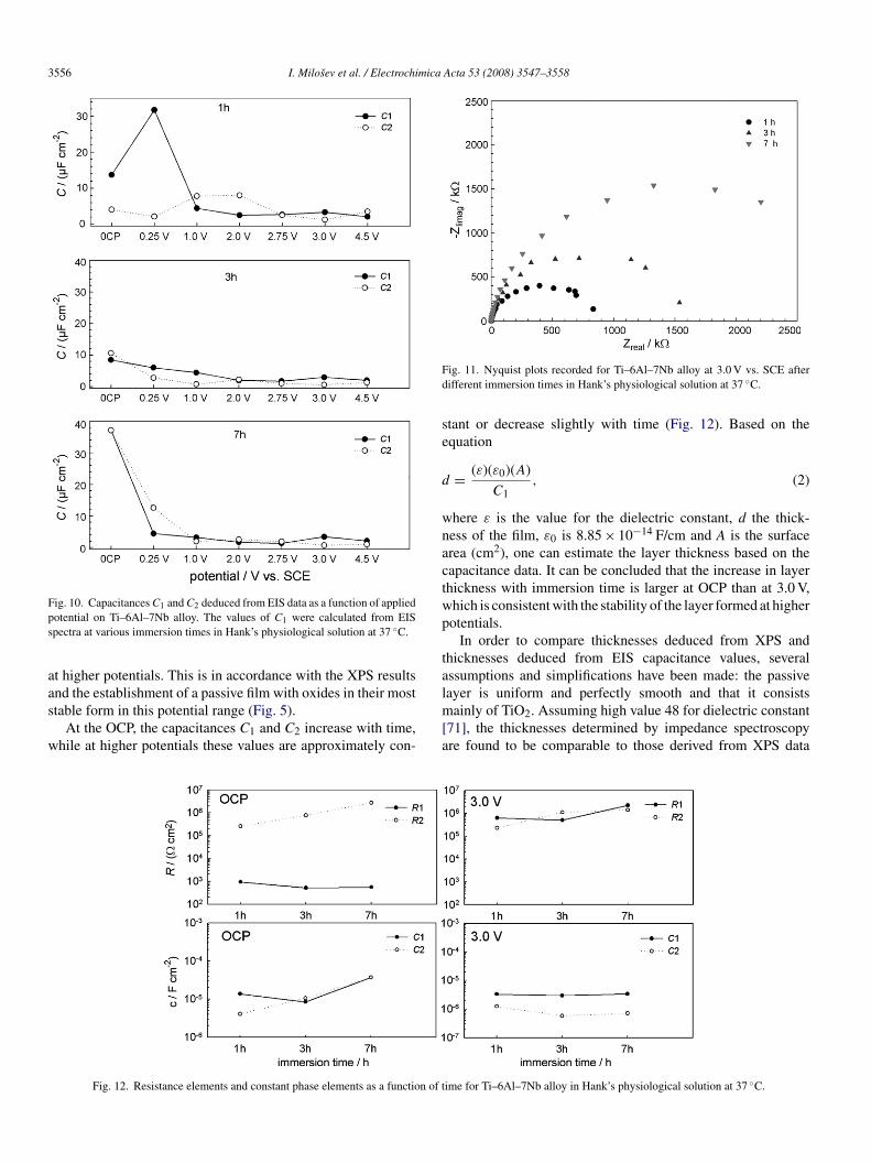
CPE, denoted as Q1 and Q2 (Table 2), were recalculated,sing equation C = [R1−nQ]1/n [70], in order to compare capac-tance values for Ti–6Al–7Nb alloy at different potentials andifferent immersion times. Values of C2 are smaller than those of1 at all observed potentials at three different immersion times,ith some exceptions at an immersion time of 1 h (Fig. 10).ecrease in C1 and C2, starting from the OCP and 0.25 V toigher potentials, can be attributed to thickening of the oxideayer. The thickening is more pronounced at lower potentials andecomes more or less constant at higher potentials (Fig. 10). Thisffect has already been observed [21] and is in accordance withhe dependence of the layer thickness on the electrode potentialbtained from our XPS data (Fig. 3). In the region of potentialsore negative than 2.0 V, the thickness increases steadily but,
t more positive potentials, does not change significantly withncreasing potential. The constant value of C2 and the observedncrease of R1 at high potentials indicate the establishment oftable passive conditions. EIS data are substantiated by our XPSesults (Figs. 1, 2 and 4–7).
Impedance responses increase with increasing immersionime (Fig. 11). There is little difference in the profiles in theigh- and medium-frequency regions, but at lower frequencieshe difference becomes substantial. The R1 element remains
ow for different immersion times at lower potentials, while R2ncreases with time (Fig. 12). At higher potentials, both R1 and2 have comparable values, pointing to the increased protec-iveness, or less defective structure, of the outer porous layer
3556 I. Milosev et al. / Electrochimica Acta 53 (2008) 3547–3558
Fps
aas
w
Fd
se
d
wnactwp
ta
ig. 10. Capacitances C1 and C2 deduced from EIS data as a function of appliedotential on Ti–6Al–7Nb alloy. The values of C1 were calculated from EISpectra at various immersion times in Hank’s physiological solution at 37 ◦C.
t higher potentials. This is in accordance with the XPS results
nd the establishment of a passive film with oxides in their mosttable form in this potential range (Fig. 5).At the OCP, the capacitances C1 and C2 increase with time,hile at higher potentials these values are approximately con-
lm[a
Fig. 12. Resistance elements and constant phase elements as a function of t
ig. 11. Nyquist plots recorded for Ti–6Al–7Nb alloy at 3.0 V vs. SCE afterifferent immersion times in Hank’s physiological solution at 37 ◦C.
tant or decrease slightly with time (Fig. 12). Based on thequation
= (ε)(ε0)(A)
C1, (2)
here ε is the value for the dielectric constant, d the thick-ess of the film, ε0 is 8.85 × 10⁻¹⁴ F/cm and A is the surfacerea (cm2), one can estimate the layer thickness based on theapacitance data. It can be concluded that the increase in layerhickness with immersion time is larger at OCP than at 3.0 V,hich is consistent with the stability of the layer formed at higherotentials.
In order to compare thicknesses deduced from XPS andhicknesses deduced from EIS capacitance values, severalssumptions and simplifications have been made: the passive
ayer is uniform and perfectly smooth and that it consistsainly of TiO2. Assuming high value 48 for dielectric constant71], the thicknesses determined by impedance spectroscopyre found to be comparable to those derived from XPS data
ime for Ti–6Al–7Nb alloy in Hank’s physiological solution at 37 ◦C.
mica
(tfofiF
4
fHeifTTcptTaoalsdp
fsclrtlcistbbaiNsnm
A
NF0aB
R
[
[[[[
[
[[[
[
[
[
[
[[[[[
[
[[
[[[[[[
[
[
I. Milosev et al. / Electrochi
Fig. 3). The deviations seem to arise from an inherent fea-ure of the passive film. Furthermore, we may not ignore theact that dielectric constant and thickness can both changever time when exposed to electrolyte, and that the passivelm is not a homogeneous dielectric material, as evidenced inig. 5.
. Conclusions
In the present study the properties of the passive oxide layerormed on Ti–6Al–7Nb alloy by electrochemical oxidation inanks’ physiological solution was studied by X-ray photo-
lectron spectroscopy in conjunction with electrochemical andmpedance methods. The potential range investigated extendsrom −0.25 V to 5.75 V. The predominant oxide formed on thei–6Al–7Nb alloy under simulated physiological conditions isiO2. After oxidation at lower potentials, E ≤ 0.75 V, this oxideontains a small amount of suboxides TiO and Ti2O3. At moreositive potentials, these suboxides are diminished and TiO2 ishe predominant oxide. At the outer oxide/solution interface theiO2 layer is enriched with oxides of the alloying elements, Alnd Nb, as evidenced by the ARXPS measurements. Aluminiumxide is present as Al2O3, while niobium oxides are formed int least two oxidation states, NbO and/or NbO2 and Nb2O5, theatter predominating (approximately 90% of the signal inten-ity). The thickness of the passive layer, calculated from XPSata, increased from 5 nm to 9 nm with increasing oxidationotential.
Electrochemical impedance spectroscopy has been exploredor in situ characterization of the electrical properties of the pas-ive film. The passive film on Ti and Ti-based alloy is generallyharacterized as a dual oxide layer comprising an inner barrierayer and an outer porous layer. For the Ti–6Al–7Nb alloy, theesistance of the barrier layer (R2) is high throughout the poten-ial range investigated, whereas that of the outer layer (R1) isow in the lower potential range but increases at E ≥ 2.75 V. At aonstant potential, the resistance also increases with increasingmmersion time. Improved resistance of the outer layer, and con-equently of the total layer, is related to the formation of oxides ofhe alloying elements in their most stable form, as demonstratedy XPS. Furthermore, the greater corrosion resistance and sta-ility of the Ti–6Al–7Nb alloy compared to the Ti–6Al–4Vlloy investigated in our previous study [15] is ascribed to thencorporation of niobium oxides, NbO, NbO2, and primarilyb2O5, into the passive layer. This result is important for the
afe long-term in vivo application of the Ti–6Al–7Nb alloy sinceiobium has the characteristics of an immunologically inertetal.
cknowledgments
Financial support by the Slovene Research Agency (Granto. P2-0148), as well as by the Internationales Buro, Deutsche
orschungsanstalt fur Luft und Raumfahrt, Bonn (Project No.17-97-01 within the bilateral collaboration between Sloveniand Germany) is greatly appreciated. The authors thank Editalazevic, B.Sc. for performing the EIS measurements.[
[
Acta 53 (2008) 3547–3558 3557
eferences
[1] J.J. Jacobs, N.J. Hallab, R.M. Urban, M.A. Wimmer, J. Bone Joint Surg.Am. 88 (Suppl. 2) (2006) 99.
[2] R.M. Urban, J.J. Jacobs, M.J. Tomlinson, J. Gavrilovic, J. Black, M. PeochM, J. Bone Joint Surg. Am. 82 (2000) 457.
[3] J.J. Jacobs, C. Silverton, N.J. Hallab, A.K. Skipor, L. Patterson, J. Black,J.O. Galante, Clin. Orthop. Relat. Res. 358 (1999) 173.
[4] J.J. Jacobs, A.K. Skipor, J. Black, R.M. Urban, J.O. Galante, J. Bone JointSurg. Am. 73 (1991) 1475.
[5] L. Savarino, M. Greco, E. Cenni, L. Cavasinni, R. Rotini, N. Baldini, A.Giunti, J. Bone Joint Surg. Br. 88 (2006) 472.
[6] H.-G. Willert, G.H. Buchhorn, M. Semlitsch, Particle disease due to wearof metal alloys, in: B.F. Morrey (Ed.), Biological, Material, and MechanicalConsiderations of Joint Replacements, Raven Press, New York, 1993, p.129.
[7] P.A. Lalor, P.A. Revell, Clin. Mater. 12 (1993) 57.[8] I. Milosev, V. Antolic, P. Campbell, A. Minovic, A. Cor, S. Herman, V.
Pavlovcic, J. Bone Joint Surg. Br. 82 (2000) 352.[9] M.L. Wang, R. Tuli, P.A. Manner, P.F. Sharkey, D.J. Hall, R.S. Tuan, J.
Orthop. Res. 21 (2003) 697.10] N.J. Hallab, S. Anderson, M. Caicedo, A. Brasher, K. Mikecz, J.J. Jacobs,
J. Biomed. Mater. Res. A 74 (2005) 124.11] Y. Okazaki, S. Rao, Y. Ito, T. Tateisji, Biomaterials 19 (1998) 1197.12] M. Semlitsch, Clin. Mater. 2 (1987) 1.13] M. Semlitsch, H. Weber, R. Steger, Biomed. Tech. 40 (1995) 347.14] S.D. Rogers, D.W. Howie, S.E. Graves, M.J. Pearcy, D.R. Haynes, J. Bone
Joint Surg. Br. 79 (1997) 311.15] I. Milosev, M. Metikos-Hukovic, H.-H. Strehblow, Biomaterials 21 (2000)
2103.16] M. Metikos-Hukovic, A. Kwokal, J. Piljac, Biomaterials 24 (2003) 2765.17] T.M. Lee, Mater. Sci. Mater. Med. 17 (2006) 15.18] C. Kuphasuk, Y. Oshida, C.J. Andres, S.T. Hovijitra, M.T. Barco, D.T.
Brown, J. Prosthet. Dent. 85 (2001) 195.19] R.J. Solar, S.R. Pollack, E. Korostoff, J. Biomed. Mater. Res. 13 (1979)
217.20] J.E.G. Gonzalez, J.C. Mirza-Rosca, J. Electroanal. Chem. 471 (1999)
109.21] I.C. Lavos-Valereto, S. Wolynec, I. Ramires, A.C. Guastaldi, I. Costa,
Mater. Sci. Mater. Med. 15 (2004) 55.22] T. Sundararajan, U. Kamachi Mudali, K.G.M. Mair, S. Rajeswari, M. Sub-
biyan, Mater. Trans. JIM 39 (1998) 756.23] S. Tamilselvi, R. Murugaraj, N. Rajendran, Mater. Corros. 58 (2007) 113.24] Y. Okazaki, T. Tateishi, Y. Ito Y, Mater. Trans. JIM 38 (1997) 78.25] M.A. Khan, R.L. Williams, D.F. Williams, Biomaterials 20 (1999) 631.26] M.A. Khan, R.F. Williams, D.F. Williams, Biomaterials 17 (1996) 2117.27] R. Silva, M.A. Barbosa, B. Rondot, M. Cunha Belo, Br. Corros. J. 25 (1990)
136.28] A.W.E. Hodgson, Y. Mueller, D. Forster, S. Virtanen, Electrochim. Acta
47 (2002) 1913.29] F. Contu, B. Elsener, H. Bohni, J. Biomed. Mater. Res. 62 (2002) 412.30] R.W.-W. Hsu, C.-C. Yang, C.-A. Huang, Y.-S. Chen, Mater. Sci. Eng. A380
(2004) 100.31] J. Lausmaa, J. Electron. Spectros. Relat. Phenom. 81 (1996) 343.32] J. Pan, D. Thierry, C. Leygraf, J. Biomed. Mater. Res. 28 (1994) 113.33] J. Pan, D. Thierry, C. Leygraf, Electrochim. Acta 41 (1996) 1143.34] S.R. Sousa, M.A. Barbosa, Clin. Mater. 14 (1993) 287.35] X. Cheng, S.G. Roscoe, Biomaterials 26 (2005) 7350.36] B. Feng, J.Y. Chen, S.K. Qi, L. He, J.Z. Zhao, X.D. Zhang, Mater. Sci.
Mater. Med. 13 (2002) 457.37] Z. Cai, H. Nakajima, M. Woldu, A. Berglund, M. Bergman, T. Okabe,
Biomaterials 20 (1999) 183.38] M. Aziz-Kerrzo, K.G. Conroy, A.M. Fenelon, S.T. Farrell, C.B. Breslin,
Biomaterials 22 (2001) 1531.39] M.V. Popa, I. Demetrescu, E. Vasilescu, P. Drob, C. Vasilescu, D. Ionita,
Electrochim. Acta 49 (2004) 2113.40] A. Choubey, R. Balasubramaniam, B. Basu, J. Alloys Compd. 381 (2004)
288.

3 mica
[[
[
[[[[
[
[[
[
[
[
[[[
[
[
[
[[[[
[
[[[
[[
558 I. Milosev et al. / Electrochi
41] M.F. Lopez, A. Gutierrez, J.A. Jimenez, Electrochim. Acta 47 (2002) 1359.42] M.F. Lopez, A. Gutierrez, J.A. Jimenez, Electrochim. Acta 48 (2003)
1395.43] N.T.C. Oliveira, E.A. Ferreira, L.T. Duarte, S.R. Biaggio, R.C. Rocha-
Filho, N. Bocchi, Electrochim. Acta 51 (2006) 2068.44] S.Y. Yu, J.R. Scully, C.M. Vitus, J. Electrochem. Soc. 148 (2001) B68.45] Y. Okazaki, E. Gotoh, Biomaterials 26 (2005) 11.46] Y. Okazaki, E. Gotoh, Mater. Trans. JIM 43 (2002) 2943.47] M.C. Advincula, D. Peterson, F. Rahemtulla, R. Advincula, J.E. Lemons,
J. Biomed. Mater. Res. 80B (2007) 107.48] A. Montenero, G. Gnappi, F. Ferrari, M. Cesari, E. Salvioli, L. Mattogno,
S. Kaciulis, M. Fini, J. Matet. Sci. 15 (2000) 2791.49] R. Narayanan, S.K. Seshadri, J. Appl. Electrochem. 36 (2006) 475.50] M.F. Maitz, M.T. Pham, W. Matz, H. Reuther, G. Steiner, Surf. Coat.
Technol. 158–159 (2002) 151.51] R. Venugopalan, J.J. Weimer, M.A. George, L.C. Lucas, Biomaterials 21
(2000) 1669.52] S. Haupt, U. Collisi, H.-H. Speckmann, H.-H. Strehblow, J. Electroanal.
Chem. 194 (1985) 179.
53] M.P. Seah, in: D. Briggs, M.P. Seah (Eds.), Practical Surface Analysis byAES and XPS, John Wiley&Sons, Chichester, New York, 1990, p. 201.54] M. Wolff, Thesis, Heinrich-Heine Universitat, Dusseldorf, 1992.55] M.P. Seah, W.A. Dench, Surf. Interface Anal. 1 (1979) 2.56] J.H. Scofield, J. Electron Spectrosc. Relat. Phenom. 8 (1976) 129.
[
[
Acta 53 (2008) 3547–3558
57] R.F. Reilman, A. Msezane, S.T. Manson, J. Electron Spectrosc. Relat.Phenom. 8 (1976) 389.
58] B. Bunshah, B.K. Gupta (Eds.), Handbook of Tribology, McGraw-Hill Inc.,New York, 1991, p. D-42.
59] G.S. Firstov, R.G. Vitchev, H. Kumar, B. Blanpain, J. Van Humbeeck,Biomaterials 23 (2002) 4863.
60] N.R. Armstrong, R.K. Quinn, Surf. Sci. 67 (1977) 451.61] C.C. Lee, H.C. Chen, C.C. Jaing, Appl. Opt. 44 (2005) 2996.62] M.K. Bahl, J. Phys. Chem. Solids 36 (1975) 485.63] R. Fontaine, R. Caillat, L. Feve, M.J. Guitter, J. Electron Spectrosc. Relat.
Phenom. 10 (1977) 349.64] V.I. Nefedov, Y.V. Salyn, A.A. Chertkov, L.N. Padurets, Zn. Neorg. Khimii.
19 (1974) 1443.65] S.F. Ho, S. Contarini, J.W. Rabalias, J. Phys. Chem. 91 (1987) 4779.66] I. Takano, S. Isobe, T.A. Sasaki, Y. Baba, Appl. Surf. Sci. 37 (1989) 25.67] C. Sittig, G. Hahner, A. Marti, M. Textor, N.D. Spencer, Mater. Sci. Mater.
Med. 10 (1999) 191.68] H.-W. Hoppe, H.-H. Strehblow, Surf. Interface Anal. 16 (1990) 271.69] I.D. Raistrick, J.R. MacDonald, D.R. Francschetti, in: J.R. MacDonald
(Ed.), Impedance Spectroscopy Emphasizing Solid Materials and Systems,John Wiley&Sons, New York, 1987.
70] D. Kek-Merl, L. Lappalainen, H.L. Tuller, J. Electrochem. Soc. 153 (2006)J15.
71] M. Kwei Lee, C.-F. Yen, J.-J. Huang, J. Electrochem. Soc. 153 (2006) F77.