
XPS® Model 3000 System User's Guide
53
XPS ® Model 3000 System User’s Guide
-
Upload
khangminh22 -
Category
Documents
-
view
1 -
download
0
Transcript of XPS® Model 3000 System User's Guide

XPS® Model 3000 System
User’s Guide

Medtronic Xomed, Inc.6743 Southpoint Drive North
Jacksonville, FL 32216-0980 U.S.A.
Authorized Representative (for EC regulatory matters)Medtronic B.V.
Earl Bakkenstraat 106422 PJ HeerlenThe Netherlands
Tel.: 011-31-45-566-8000Fax: 011-31-45-566-8668
Rx Only
™ are trademarks and ® are registered marks of Medtronic Xomed, Inc.
Copyright© 2005 Medtronic Xomed, Inc.Made in U.S.A.
The information contained in this document was accurate at time of publication. Medtronic Xomed reserves the right tomake changes in the product described in this manual without notice and without incorporating those changes in anyproducts already sold.

i
TABLE OF CONTENTS
Symbols ............................................................................................................................................ iiiWhen the System Arrives ................................................................................................................. ivWarnings and Precautions ........................................................................................................... iv-viCustomer Service ............................................................................................................................. viiDevice Description ............................................................................................................................ 1
System Description .................................................................................................................... 1Indications ................................................................................................................................. 2Contraindications ....................................................................................................................... 2
Parts List .......................................................................................................................................... 3XPS® 3000 Console Description ...................................................................................................... 4
Front Console ............................................................................................................................. 4Rear Console .............................................................................................................................. 5
XPS® 3000 Set-Up and Use ............................................................................................................... 6Cable Connections ..................................................................................................................... 6Console Set-Up ....................................................................................................................... 6-7
Language Selection ................................................................................................................ 6XPS® Multifunction Footswitch, 1895400 ................................................................................ 10XPS® Multifunction Footswitch, Single Pedal, 1895420 ........................................................... 10XPS® Single Function Footswitch, 1895410 ............................................................................. 10
XPS® StraightShot® M4 and Magnum® II Microdebrider System Set-Up and Use ........................ 11Before Surgery .....................................................................................................................11-12
XPS® StraightShot® M4 and Magnum® II Handpiece Accessories ................................................ 13Blade or Bur Installation ........................................................................................................... 14Tubing Attachment .................................................................................................................. 14XPS® StraightShot® M4 and Magnum® II Surgical Precautions ............................................... 14After Surgery ............................................................................................................................ 15
Blade or Bur Removal ........................................................................................................... 15Visao™ and Xcalibur® Drill System Set-Up and Use ...................................................................... 16
Before Surgery ......................................................................................................................... 18Visao™ and Xcalibur® Bur Installation and Tubing Attachment ............................................... 19
Bur Attachment ..................................................................................................................... 19Curved Bur Installation ......................................................................................................... 19Tubing Attachment-Irrigation ............................................................................................... 19Tubing Attachment-Cooling ................................................................................................. 20
Visao™ and Xcalibur® Surgical Precautions .............................................................................. 20Powerforma® Drill System Set-Up and Use .................................................................................... 21
Before Surgery ......................................................................................................................... 22Powerforma® Bur Installation and Tubing Attachment ............................................................ 23
Bur Attachment ..................................................................................................................... 23Tubing Attachment-Irrigation ............................................................................................... 23
Powerforma® Surgical Precautions ........................................................................................... 23Skeeter® Ultra-Lite Oto-Tool System Set-Up and Use ................................................................... 24
Before Surgery ......................................................................................................................... 26

ii
Cleaning and Sterilization Guidelines ........................................................................................... 27Precaution ................................................................................................................................ 27Warnings .................................................................................................................................. 27After Surgery ........................................................................................................................ 27-28Cleaning ............................................................................................................................... 28-30Sterilization ........................................................................................................................... 31-34
Warnings .............................................................................................................................. 31Precautions ........................................................................................................................... 31
Sterilization References ............................................................................................................ 34Troubleshooting .............................................................................................................................. 35
System Malfunctions ............................................................................................................... 35Blade or Bur Malfunctions ....................................................................................................... 35Drill and Handpiece Malfunctions ........................................................................................... 36Footswitch Malfunctions ......................................................................................................... 36
Limited Warranty and Repair ......................................................................................................... 37Technical Specifications ................................................................................................................. 38
Handpieces - XPS® StraightShot® M4 Microdebrider, StraightShot® Magnum® II,LandmarX® Magnum® II, XPS® StraightShot® III (Japan only) ................................................ 38Visao™ and Xcalibur® Drills ..................................................................................................38-39MPS® Powerforma® Drill ........................................................................................................... 39Skeeter® Ultra-Lite Oto-Tool ..................................................................................................... 39Console .................................................................................................................................... 39XPS® Multifunction Footswitch, 1895400 ................................................................................ 40XPS® Multifunction Footswitch, Single Pedal, 1895420 ........................................................... 40XPS® Single Function Footswitch, 1895410 ............................................................................. 40
Compliance ..................................................................................................................................... 40Guidance and manufacturer’s declaration – electromagnetic immunity - Part I .......................... 41Guidance and manufacturer’s declaration – electromagnetic emissions ..................................... 42Recommended separation distances between portable and mobile RF communicationsequipment and the XPS® 3000 ........................................................................................................ 42Guidance and manufacturer's declaration - electromagnetic immunity - Part II .......................... 43Recommended Environmental Conditions ...................................................................................... 43
LIST OF FIGURES
Figure 1 Front Console ................................................................................................................. 4Figure 2 Rear Console ................................................................................................................... 5Figure 3-A Control Button Cluster-Standard Mode .......................................................................... 7Figure 3-B Control Button Cluster-Procedure Mode ........................................................................ 7Figure 4 Default Displays and Settings ........................................................................................ 8Figure 5 Menu Flow Diangram ...................................................................................................... 9Figure 6-A XPS® Multifunction Footswitch, 1895400 ...................................................................... 10Figure 6-B XPS® Multifunction Footswitch, Single Pedal, 1895420 ................................................. 10Figure 7 XPS® Single Function Footswitch, 1895410 ................................................................... 10Figure 8 XPS® StraightShot® M4 and Magnum® II Microdebrider System .................................. 12Figure 9 Blade or Bur Installation ................................................................................................ 14Figure 10 Tubing Attachment ........................................................................................................ 14Figure 11 Xcalibur® Hi-Torque Drill System................................................................................... 16Figure 12 Visao™ High-Speed Otologic Drill or
Xcalibur® Hi-Speed Drill System .................................................................................... 17Figure 13 Powerforma® Drill System .............................................................................................. 21Figure 14 Skeeter
® Ultra-Lite Oto-Tool System .............................................................................. 25

iii
SYMBOLS
ATTENTION, SEE INSTRUCTIONS FOR USE
CATALOG NUMBER
SERIAL NUMBER
DATE OF MANUFACTURE
USE BY DATE
DO NOT REUSE
STERILIZED BY ETHYLENE OXIDE.DO NOT USE IF PACKAGE IS OPENED OR DAMAGED.
STERILIZED BY RADIATION.DO NOT USE IF PACKAGE IS OPENED OR DAMAGED.
LOT NUMBER
ON (MAIN POWER)
OFF (MAIN POWER)
REVERSE
FORWARD
OSCILLATION
FOOTSWITCH — VARIABLE MODE
FOOTSWITCH — START/STOP
FOOTSWITCH
FOOTSWITCH DIRECTION - FORWARD
FOOTSWITCH DIRECTION - OSCILLATE
FOOTSWITCH DIRECTION - REVERSE
TYPE B APPLIED PART
ACCESSORY CONNECTOR
MANUAL START/STOP
HANDPIECE
SKEETER® HANDPIECE
RF TRANSMITTER (INTERFERENCE MAY OCCUR)
CAUTION: PINCH HAZARD. KEEP FINGERS CLEAR OF ROLLERS.
A
C
N
D
U
2
E
R
B
ACC
LOCKED
UNLOCKED
IRRIGANT
COOLANT
PUMP
MENUMENU

iv
WHEN THE SYSTEM ARRIVES
UNPACKING AND INSPECTION
As the box is unpacked, check off the contents of the box against the items listed on the packing slip. If the contentsare incomplete or if there is damage, notify Customer Service. If the shipping container is damaged, or the cushioningmaterial shows signs of stress, notify the carrier as well.
Keep the shipping materials for carrier inspection.
After unpacking your new XPS® Model 3000 System, save the cartons and packing material. If the instrument is tobe shipped from one location to another, the carefully designed shipping package will provide proper protection.
WARNINGS AND PRECAUTIONS
It is important that the XPS® Model 3000 operator be familiar with this manual: its precautions, procedures andsafety issues. Three labels are used in this manual to identify important concerns, conditions, or procedures:
“WARNING”Identifies conditions or practices that present a risk of injury to the patient and/or user.
"PRECAUTION / CAUTION"Identifies conditions or practices that could result in damage to the equipment.
"NOTE"Identifies special information allowing easier maintenance of equipment or to clarify or emphasize importantinstructions.
WARNINGS• Always inspect the components before and after use for any damage. If damage is observed, do not use damaged
part until it is replaced. Damaged parts may deposit metal shavings on surgical site.• Do not modify accessories used with the handpiece. Performance could be diminished with modified accessories.• Insertion of metal objects in blade or bur tip may cause the blade or bur to break leaving fragments in the wound.
The fragments may be difficult to remove, causing irritation, inflammation and foreign-body response at surgicalsite.
• Do not use any parts other than Medtronic Xomed, Inc. system components as damage or substandard performancecould result.
• Blade and bur accessories are available for resection of soft tissue and bone for surgical procedures. Use ofaccessories depends on the intended application and patient needs. Sharp-cutting powered accessories inducebleeding and removal of significant tissue and bone.
• Do not attach unapproved components to the XPS® 3000 Console to avoid electrical macro shock.• Carefully inspect burs prior to and following each use for excessive wear, fragmentation, eccentricities or other
defects. Do not use dull, damanged or bent burs. Use of dull burs can reduce the handpiece effectiveness andcause the handpiece temperature to increase.
• Do not attempt to resharpen used burs. Worn burs should be replaced with new ones frequently to ensureeffective cutting and control of the drill.
• Excessive pressure applied to bur may cause bur fracture. Should a bur fracture during use, extreme care must beexercised to ensure that all fragments of the bur are retrieved and removed from the patient. Unremoved burfragments may cause tissue damage to the patient.
• Test for bur wobble (eccentricity) at desired speed prior to use. Use a bur guard (Xcalibur only) if needed. Selecta new bur or reduce speed if wobble is observed.
• Test for bur wobble (eccentricity) at the desired speed prior to use. Select a new bur or reduce speed if wobble isobserved. Eccentricity of the bur can cause bur vibration and may result in excessive tissue and bone destructionand hearing damage. Always examine the operation of each bur in the handpiece before each use. Operatingcertain burs at high speed can cause vibration of the bur.
• Keep the cooling sleeve irrigated to prevent thermal injury to tissue.• During procedures near nerves, keep bur and bur cannula away from tissue to minimize the potential for thermal
injury.

v
WARNINGS (continued)• For procedures near nerves, nerve monitoring should be used to alert the user of the potential for injury.• Use care in application of the moving cutting end to only appropriate anatomical landmarks and the intended
surgical site when using XPS® accessories. The use of powered reciprocating/rotating instruments may result invibration-related injury. Use appropriate precautions.
• Employ visualization when using rotating XPS® accessories. Discontinue powered application in the event oflack of visualization of the surgical site.
• Use methods at the operative site to control bleeding that do not compromise patient safety during at-risksurgery.
• Use lock on StraightShot® M4 handpiece to prevent inadvertant rotation of blade or bur during use.• When precise location of the blade tip is required, engage the rotation lock on the handpiece, then calibrate and
verify the blade tip on the Image Guided Surgery (IGS) system. Always lock the StraightShot® M4 handpiecewhen driving non-rotatable blades to maintain their IGS calibration.
• Always keep the cutting tip of the accessory away from fingers and loose clothing. Prevent laceration of user andcross-contamination through compromised glove.
• Do not change accessory with handpiece running to prevent laceration of user and cross-contamination throughcompromised glove.
• Bending or prying may break the blade or bur, causing harm to patient or staff.• Discontinue use of curved bur if tip begins to wobble and replace bur to prevent unintended tissue removal from
patient.• Do not use burs above the speed indicated on the bur label. Exceeding speed may cause the burs to break.• Disposable devices are for single-use only. Do not attempt to sterilize disposable devices. The disposables are
packed sterile and not intended for repeat use. To prevent contamination use only once.• Disconnect power to the XPS® 3000 Console before cleaning the unit to avoid electrical macro shock.• After each procedure, properly clean all reusable system components.• Sterilize and dry reusable device before storing the system. Decrease likelihood of cross-contamination with
timely sterilization.• Remove and discard accessories following local regulations for proper disposal of contaminated materials.• Properly dispose of single-use devices removed from sterile packages. Devices lost sterility upon removal from
packaging.• All service must be performed by Medtronic Xomed-qualified personnel only.
WARNINGS BEFORE SURGERY• Verify reusable device was sterilized prior to use. If not sterilized, do not use.• Do not use accessory if package is opened or damaged. Broken seal offers no protection against cross-
contamination.• Do not operate the XPS® 3000 System in the presence of flammable anesthetics. Avoid potential ignition or
explosion of gases.• Achieve electrical grounding reliability with proper connections. Connect the XPS® 3000 Console to hospital
grade receptacles only.• Use adequate irrigation from a separate user-provided irrigating source. The use of a bur without irrigation may
cause an inordinate amount of heat buildup resulting in thermal injury to tissue.• When not operating handpiece, ensure that handpiece rests on a non-conductive surface that provides containment
for handpiece and blade/bur. Avoid unintended thermal injury by an uncontained handpiece.• When not operating handpiece, eliminate accidental foot control activation. Control energy to and through
handpiece to prevent unintended tissue, bone or nerve resection.• This medical device complies with EN60601-1-2 safety standard for electromagnetic compatibility, requirements
and test. However, if this equipment is operated in the presence of high levels of electromagnetic interference(EMI) or highly sensitive equipment, interference may be encountered and the user should take whatever stepsare necessary to eliminate or reduce the source of the interference. Diminished performance may lengthen operatingtime for anesthetized patient.
PRECAUTIONS• XPS® Blades should be operated in the oscillate mode only. Operating in the forward mode may cause damage to
the blade. XPS® burs should be operated in the forward mode only.• The handpiece should be evaluated prior to each use for suitable operating condition.• System components should be operated and inspected for damage prior to use. Do not use system if damage is
apparent.

vi
NOTICEIt is important that you read this entire manual
before you use the XPS® Systems. It is unsafe to
use these devices before you have read and are
thoroughly familiar with this document.
PRECAUTIONS (continued)• It is recommended that a secondary handpiece be available to minimize any downtime and inconvenience to the
surgical staff.• The StraightShot® Magnum® II and StraightShot® M4 Microdebriders are intended to operate at speeds greater
than 6,000 rpm ONLY when used with the XPS® High Speed bur line.• Always ensure that the bur is securely engaged into the handpiece prior to operating the system.• When operating or testing the Poweforma®, Xcalibur® and Visao™ drill handpieces, ensure the bur is properly
inserted and locked into the handpiece. Running the drill with the collet unlocked can damage the lockingmechanism.
• Improper priming of the Xcalibur® and Visao™ Hi-Speed Drills will result in excessive handpiece temperature.• The Xcalibur® and Visao™ High-Speed Water-Cooled Drills work only with the XPS® 3000. Use without water-bag
will damage the motor in the handpiece.• Do not allow the console or footswitch to get wet. If liquid enters the console or footswitch, damage could occur.• To prevent damage to curved blades and burs, disconnect suction tube prior to changing blade or bur during
procedure.• DO NOT clean handpieces in ultrasonic cleaner or allow them to be fully immersed in any soaking solution. These
procedures may result in damaging the handpieces beyond repair.• Do not sterilize the console or footswitch.• Do not clean the handpiece in an ultrasonic cleaner or cold soak sterilize the handpiece in glutaraldehyde. Do not
immerse handpieces, motors, or handpiece cables in any solution, except as detailed in the Cleaning section ofthis manual. These procedures void the warranty and may damage the handpiece beyond repair.
• Always handle handpieces with care to avoid damage.• Do not use organic solvents such as acteone or isopropyl alcohol to clean the bur chuck. Use only an enzymatic
detergent and distilled water for cleaning after every case or as required.• Remove the bur from the handpiece before sterilization.• Sterilize immediately after cleaning. Do not store unless a drying cycle has been performed.• Always wrap the electrical cord carefully inside the sterilization tray during sterilization to prevent damage to the
cord when closing the tray lid.• Remove the handpiece from the sterilizer immediately after the sterilization cycle is complete.• Temperatures higher than those stated may be used for handpiece sterilization when necessary to satisfy
governmental or health care facility requirements so long as the temperature does not exceed 149°C (300ºF).Heating above 149°C (300ºF) may damage components and will void the warranty.
• Regardless of which type of steam sterilization is used, it is extremely important that the handpiece is rapidly andcompletely dried before it is stored. Do not operate or store the handpiece unless a drying cycle has beenpreformed. If a vacuum drying cycle is not used following steam sterilization, moisture may be trapped within thehandpiece causing corrosion and residue deposits, resulting in premature wear and a reduction in the functionallife expectancy of the handpiece. In addition, damage may result if the handpiece is operated with moisture in theelectronic connections.
• Store system in a clean dry place.• Medical Electrical Equipment needs special precautions regarding EMC and needs to be installed and put into
service according to the EMC information provided in this Guide.• Portable and mobile RF communications equipment can affect Medical Electrical Equipment.• Use of accessories and cables other than those specified and sold by Medtronic Xomed may result in increased
emissions and decreased immunity of this unit.• The XPS® 3000 should not be used adjacent to or stacked with other equipment. If adjacent or stacked use is
necessary, the XPS® 3000 should be observed to verify normal operation in the configuration in which it will beused.

vii
CUSTOMER SERVICE
U.S. CUSTOMER SERVICEGeneral customer service and technical support are available toll-free:800-874-5797 or 904-296-9600Monday-Friday8:00 AM - 6:00 PM E.S.T.www.xomed.com
MICROELECTRONICS REPAIRTechnical Support:800-872-9877904-296-6448 (FAX)Monday - Friday8:00 AM - 5:00 PM E.S.T.
Return Address:Medtronic Xomed, Inc.4102 Southpoint Blvd.Jacksonville, FL 32216-0980 U.S.A.Attention: Repair Department
CUSTOMER SERVICE INFORMATIONFor further information regarding the use of this product or to report any problems, please contact MedtronicXomed using the appropriate information provided on the blue and white contact information card packaged witheach device; or contact your local distributor.
MEDTRONIC XOMED, INC. HELPLINEShould you need immediate help with a technical question or guidance through the appropriate protocol, just callthe Medtronic Xomed Help Line at 1-800-874-5797.
NOTE:When contacting our Customer Service and Technical Support, please have the appropriate product number,product serial number, date of purchase, and nature of inquiry available.
Product Number
Serial Number
Date of Purchase

1
DEVICE DESCRIPTION
SYSTEM DESCRIPTION
The XPS® 3000 System consists of a power control console, footswitches, connection cables, and assortedhandpieces to drive various burs, blades, drills, rasps, and cannulae.
XPS® 3000 CONSOLE — Provides power to the selected handpiece. In addition to the StraightShot® M4Microdebrider and Visao™ High-Speed Otologic Drill, the system console also powers the StraightShot® Magnum®
and Magnum® II handpiece, Powerforma® (High Speed Drill), Xcalibur® Hi-Torque and Hi-Speed Drills, and Skeeter®
(microdrill) handpieces. It includes an integrated irrigation pump for irrigation of blades and burs and a secondpump (optional) for motor coolant of the Visao™ High-Speed and Xcalibur® Hi-Speed Otologic Drills.
FOOTSWITCH — The Single Function footswitch controls speed; the Multifunction footswitch controlshandpiece speed, rotation mode, and footswitch mode.
XPS® STRAIGHTSHOT® M4 MICRODEBRIDER — Features a finger wheel that allows the user to rotate thecutting tip of specially designed straight and curved rotatable blades. It is also compatible with non-rotating bladesand burs. It includes a locking mechanism to prevent inadvertent rotation of non-rotating blades. The lightweightdesign combines high power and precision performance and can operate in forward mode of 12,000 rpm for buroperation and 5,000 rpm in oscillate for blade operation. The StraightShot® M4 also provides irrigation tubingmanagement grooves to keep tubing out of the surgeon’s way during a procedure.
STRAIGHTSHOT® MAGNUM® II MICRODEBRIDER HANDPIECE — Features a locking mechanism and allowsadjustability of blade or bur tip alignment. The lightweight design combines high power and precision performanceand can operate in forward mode of 12,000 rpm for bur operation and 5,000 rpm oscillate for blade operation.
STRAIGHTSHOT® MAGNUM® HANDPIECE — Features a locking mechanism and allows adjustability of bladeor bur tip alignment. The lightweight design combines high power and precision performance.
VISAO™ HIGH-SPEED OTOLOGIC DRILL — The lightweight design is used in otologic bone drilling operations.It may be used with either standard burs or with Visao™ High-Speed Curved Burs.
XCALIBUR® HI-TORQUE AND HI-SPEED (WATER-COOLED) OTOLOGIC DRILLS — Has two motorassemblies, one hi-torque and one hi-speed (Water-Cooled); and one straight and one angled handpiece attach-ment. It is used in otologic bone drilling operations.
SKEETER® ULTRA-LITE OTO-TOOL — A slender, lightweight drill handpiece and burs specifically used inmiddle ear surgical procedures, including stapes footplate procedures. The Skeeter® may be powered from the XPS®
3000 console, XPS® 2000 console, or from a battery powered variable speed foot control.
POWERFORMA® OTOLOGIC DRILL — Straight and angled drill handpieces for otologic bone drilling. ThePowerforma® connects, via an adapter plug, to the XPS® 3000 and XPS® 2000 consoles.

2
INDICATIONS
The XPS® 3000 is intended for the incision and removal of soft and hard tissue or bone in general otorhinolaryngol-ogy, head and neck, and otoneurological surgery. An integral pump is provided for irrigation and a second integralpump may be provided for handpiece cooling.
Otology / neurotology indications include aural atresia, cholesteatoma, cochleostomy, development of a suturetunnel for cochlear implant fixation, drainage of petrous apex cyst from endaural and middle-fossa approach,endolymphatic hydrops, exostosis lesion removal, facial nerve decompression, mastoidectomy, mastoidotomy,ossicular chain reconstruction (OCR), otosclerosis, removal of ear tumors including acoustic neuroma, tympano-plasty and vestibular neurectomy.
Sinus indications include septoplasty, removal of septal spurs, polypectomy, antrostomy, ethmoidectomy/sphenoethmoidectomy, frontal sinus trephination and irrigation, frontal sinus drill out, endoscopic DCR, trans-sphenoidal procedures, maxillary sinus polypectomy, circumferential maxillary antrostomy, choanal atresia,sphenoidectomy, and medial, lateral, and posterior frontal sinusotomy.
Nasopharyngeal/laryngeal indications include adenoidectomy, tracheal procedures, laryngeal polypectomy, laryn-geal lesion debulking, including the surgical management of recurrent respiratory papillomatosis (RPP), and tonsil-lectomy, tonsillotomy for obstructive tonsillar disease and removal of endobronchial lesions.
Head and neck (ENT) indications include soft tissue shaving, rhinoplasty (narrowing of the bony vault and revisionof the bony pyramid), removal and shaping of bone during rhinoplasty procedures, removal of adipose tissue (lipodebridement) in the maxillary and mandibular regions of the face, removal of acoustic neuroma, and incision andremoval of soft tissue during plastic, reconstructive, and/or aesthetic surgery.
The XPS® 3000 system is indicated for use in orthopedic surgical procedures where the cutting and removal of softand hard tissue or bone is required. These include spinal and small and large joint arthroscopic procedures.
CONTRAINDICATIONS
None are known.

3
PARTS LIST
Part # Description1897101 ................................ XPS® Model 3000 Console With Irrigation (one pump)1897102 ................................ XPS® Model 3000 Console With Coolant and Irrigation (two pumps)1898200T ............................. XPS® StraightShot® M4 Microdebrider1897200 ................................ StraightShot® Magnum® II Handpiece1897200T ............................. LandmarX® Magnum® II Handpiece1897201 ................................ XPS® StraightShot® III Handpiece (Japan only)1895400 ................................ XPS® Multifunction Footswitch1895410 ................................ XPS® Single Function Footswitch1895420 ................................ XPS® Multifunction Footswitch, Single Pedal1895505 ................................ XPS® Accessory Cable, Short1895820 ................................ Power Cord, North American, 115V1895821 ................................ Power Cord, United Kingdom/Ireland, 240V1895822 ................................ Power Cord, Continental Europe, 230V1895823 ................................ Power Cord, Japan, 100V1897821 ................................ Power Cord, 6 Meter, IEC320, 115V3334800 ................................ Visao™ High-Speed Otologic Drill3334800T ............................. Visao™ High-Speed Otologic Drill, IGS Trackable3333700 ................................ Xcalibur® Straight Hi-Torque Handpiece Attachment3333705 ................................ Xcalibur® Straight Hi-Speed Handpiece Attachment3333750 ................................ Xcalibur® Angled Hi-Torque Handpiece Attachment3333755 ................................ Xcalibur® Angled Hi-Speed Handpiece Attachment3333840 ................................ Xcalibur® Hi-Speed Motor Assembly, Water-Cooled3333850 ................................ Xcalibur® Motor Assembly (Hi-Torque)Accessories1895520 ................................ Powerforma® to XPS® Irrigator Tubing1895522 ................................ StraightShot® to XPS® Irrigation Tubing, 5/Bx1896840 ................................ StraightShot® Magnum® Sterilization Tray1897510 ................................ XPS® IV Pole Basket for Footswitch1897851D ............................. XPS® Model 3000 System User’s Guide1897852 ................................ XPS® Model 3000 System Repair Manual1898400 ................................ XPS® StraightShot® M4 Sterilization Tray1994025 ................................ Adapter for Powerforma® Handpiece3055601 ................................ Skeeter® Ultra-Lite Oto-Tool3318501 ................................ Powerforma® Irrigation Tubing, Non-Sterile3318502 ................................ Powerforma® Irrigation Tubing, Sterile, 5/bx3318503 ................................ Irrigation Tubing Set, Sterile, 4/bx3318506 ................................ Hi-Speed Drill Coolant Tubing Set, 2/bx3318510 ................................ Handpiece Cable Cap, Small3318515 ................................ Handpiece Cable Cap, Large3318600 ................................ Clips for MPS®/Powerforma®/Xcalibur® Handpiece Cable/Tubing3319001 ................................ MPS® Powerforma® Sterilization Tray3319005 ................................ Case, Bur Rack, MPS®
3327700 ................................ MPS® Powerforma® Straight Handpiece3327750 ................................ MPS® Powerforma® Angled Handpiece3333610 ................................ Xcalibur® Irrigation Sleeve Assembly3333620 ................................ Xcalibur® Hi-Torque Extended Bur Guard, Without Irrigation3333625 ................................ Xcalibur® Hi-Speed Extended 75 mm Bur Guard, Without Irrigation3333630 ................................ Xcalibur® Hi-Torque Extended Bur Guard, With Irrigation3333635 ................................ Xcalibur® Hi-Speed Extended 75 mm Bur Guard, With Irrigation3333645 ................................ Xcalibur® Hi-Speed Extended 64 mm Bur Guard, Without Irrigation3333655 ................................ Xcalibur® Hi-Speed Extended 64 mm Bur Guard, With Irrigation3333890 ................................ Xcalibur® Sterilization Tray3333895 ................................ Xcalibur® Hi-Speed Drill Sterilization Tray3334610 ................................ Visao™ Irrigation Sleeve3334625 ................................ Visao™ Extended Bur Guard, Without Irrigation3334635 ................................ Visao™ Extended Bur Guard, With Irrigation3334895 ................................ Visao™ Sterilization Tray
For a complete list of system components and accessories contact your local Medtronic Xomed representative or call CustomerService at 1-800-874-5797 or 1-904-296-9600.

4
XPS® 3000 CONSOLE DESCRIPTION
FRONT CONSOLE
1. SPEED DISPLAY – When the system is running, the actual operating speed of the handpiece displays. Wheninactive, the display shows the top speed set by the operator.
2. ROTATION INDICATOR – Displays rotation mode (forward, reverse, or oscillate). Lights indicate selectedrotation. Rotation may be selected at either the multi-function footswitch or with the center control button in thenormal mode.
3. PROCEDURE AND CURRENT OPERATIONS DISPLAY – In operating mode, displays procedure-blade/bursetting and irrigation pump rate. In procedure selection/menu mode, it displays a choice of procedures, allowingthe user to choose suggested operational settings for the current procedure.
4. CONTROL BUTTON CLUSTER – Operates in two modes, Normal and Procedure. In Normal operation, centerbutton controls direction (forward and oscillate), top and bottom buttons control speed (increase and decrease),and left and right button control rate of irrigation (decrease and increase). Depressing the menu button activatesthe Procedure Mode. Arrow buttons control the cursor and the center button is the Select button. Operation ofthe speed and procedure functions is described below.
5. HANDPIECE CONNEC-TORS – Connect the ap-propriate handpiece to theconsole here. (Large con-nector for all handpiecesexcept for Skeeter® hand-piece.)
6. FOOTSWITCH CON-NECTOR – Connect thefootswitch to the consolehere. During standard op-eration the footswitchmust be connected to op-erate the active handpiece.
7. HANDPIECE IRRIGA-TION PUMP – Pumpsfluid through a tubing setto the blade or bur.
8. XCALIBUR® HI-SPEEDWATER COOLANTPUMP –Pumps cooling fluid forthe Water -Cooled drillmotor assembly (avail-able only on REF#1897102).
Figure 1 Front Console

5
REAR CONSOLE
1. MANUAL START STOP BUTTON – In the case of footswitch failure intraoperatively, button allowscirculating nurse to manually turn handpiece operation on and off.
2. ENDO-SCRUB® CABLE CONNECTOR – Accepts accessory cable which powers the Endo-Scrub® 2.
3. FUSE ACCESS – REPLACE ONLY WITH 250V, 4.0A, Type F, 5 x 20mm fuses.
4. POWER SWITCH – Press the power switch to the “|” position to turn on the system. Press the switch to the“O” position to turn the system off.
5. POWER CORD CONNECTOR – Hospital grade power cord connects here.
6. DB-9 CONNECTOR – Connector for future data exchange.
Figure 2 Rear Console

6
XPS® 3000 SET-UP AND USE
CAUTION
Inspect components for damage before use. Do not operate if components are damaged.
CABLE CONNECTIONS
To connect the cables to the console:1. Insert the cable connectors by aligning the red dot on the cable connector with the red dot on the console
connector.2. Push connectors together. They should lock in place.
To disconnect the cables from the console:1. Grasp the cable connector and gently pull back on the collar of the connector.2. The connector will disconnect.
CAUTION
Grasp the cable connector; do not pull on the cable.
CONSOLE SET-UP
LANGUAGE SELECTIONThe system is provided with a one pump console (1897101) or two pump console (1897102) defaulted to thecustomer’s preferred language. Each console is capable of displaying six (6) languages as indicated below:
To change the language selection, simultaneously press the left and right arrow key on the control button cluster.Next, a menu will appear on the display showing the language choices. Use the arrow keys to move the cursor to thedesired language and press the center key to select.
PRECAUTIONS• System components should be operated and inspected for damage prior to use. DO NOT USE SYSTEM IF
DAMAGE IS APPARENT.• Do not allow the console to get wet. If liquid enters the console, damage could occur.
WARNING
• Only connect the console to hospital grade receptacles to ensure electrical grounding reliability.
1. Plug the power cord into the console and into the wall outlet.2. Connect the handpiece (s) to the appropriate console connector (s).3. Connect the footswitch cable to the console. See next section for instructions on footswitch operation.4. Turn the console on by pressing the power switch on the back panel. The console will display default
settings for the handpiece speed, direction of cutter rotation, and type of surgical procedure.5. Figures 4 and 5 shows the default settings in Normal and Procedure Mode.
Two Pumps - 1897102
EnglishFrenchItalianGermanSpanishDutch
One Pump - 1897101
EnglishFrenchItalianGermanSpanishDutch
Two Pumps - 1897102
EnglishSpanishDanishFinnishSwedishPortuguese
One Pump - 1897101
EnglishSpanishDanishFinnishSwedishPortuguese
7
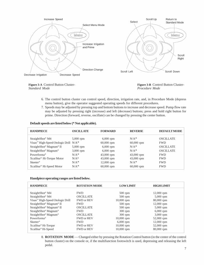
6. The control button cluster can control speed, direction, irrigation rate, and, in Procedure Mode (depressmenu button), give the operator suggested operating speeds for different procedures.
7. Speeds may be adjusted by pressing top and bottom buttons to increase and decrease speed. Pump flow ratemay be adjusted by pressing right (increase) and left (decrease) buttons; press and hold right button forprime. Direction (forward, reverse, oscillate) can be changed by pressing the center button.
Default speeds are listed below (* Not applicable).
HANDPIECE OSCILLATE FORWARD REVERSE DEFAULT MODE
StraightShot® M4 5,000 rpm 6,000 rpm N/A* OSCILLATEVisao™ High-Speed Otologic Drill N/A* 60,000 rpm 60,000 rpm FWDStraightShot® Magnum® II 5,000 rpm 6,000 rpm N/A* OSCILLATEStraightShot® Magnum® 3,000 rpm 6,000 rpm N/A* OSCILLATEPowerforma® N/A* 43,000 rpm 43,000 rpm FWDXcalibur® Hi-Torque Motor N/A* 43,000 rpm 43,000 rpm FWDSkeeter® N/A* 12,000 rpm N/A* FWDXcalibur® Hi-Speed Motor N/A* 60,000 rpm 60,000 rpm FWD
Handpiece operating ranges are listed below.
HANDPIECE ROTATION MODE LOW LIMIT HIGH LIMIT
StraightShot® M4 FWD 500 rpm 12,000 rpmStraightShot® M4 OSCILLATE 500 rpm 5,000 rpmVisao™ High-Speed Otologic Drill FWD or REV 10,000 rpm 80,000 rpmStraightShot® Magnum® II FWD 500 rpm 12,000 rpmStraightShot® Magnum® II OSCILLATE 500 rpm 5,000 rpmStraightShot® Magnum® FWD 300 rpm 6,000 rpmStraightShot® Magnum® OSCILLATE 300 rpm 3,000 rpmPowerforma® FWD or REV 10,000 rpm 52,000 rpmSkeeter® FWD 6,000 rpm 12,000 rpmXcalibur® Hi-Torque FWD or REV 10,000 rpm 52,000 rpmXcalibur® Hi-Speed FWD or REV 10,000 rpm 80,000 rpm
8. ROTATION MODE — Changed either by pressing the Rotation Control button (in the center of the controlbutton cluster) on the console or, if the multifunction footswitch is used, depressing and releasing the leftpedal.
Figure 3-A Control Button Cluster-Standard Mode
Decrease Irrigation
Select Menu Mode
Increase Irrigationand Prime
Decrease Speed
Increase Speed
Direction Change
Figure 3-B Control Button Cluster-Procedure Mode
Select
Scroll Left Scroll Down
ScrollRight
Scroll Up Return toStandard Mode

8
INS
ER
T H
AN
DP
IEC
E
HA
ND
PIE
CE
DETEC
TED
?
No
WH
ICH
HA
ND
PIE
CE?
MA
GN
UM
HI-S
PD
DR
ILL
DR
ILL
Ye
s
Defa
ult
Dis
pla
ys and
Sett
ings
MA
GN
UM
II
& M
4
SK
EE
TE
R
30
00
rpm
SIN
US
BL
AD
EO
SC
ILL
AT
EIR
RIG
AT
ION
4
0%
60
00
0rp
m
MA
ST
OID
BU
RF
OR
WA
RD
IRR
IGA
TIO
N
4
0%
43
00
0rp
m
MA
ST
OID
BU
RF
OR
WA
RD
IRR
IGA
TIO
N
4
0%
50
00
rpm
SIN
US
BL
AD
EO
SC
ILLA
TE
IRR
IGA
TIO
N
4
0%
12
00
0rp
m
MID
DL
E E
AR
SK
EE
TE
RF
OR
WA
RD
IRR
IGA
TIO
N
O
FF
Figu
re 4
Def
ault
Dis
play
s an
d Se
tting
s
9
Defa
ult
Handpie
ce
Dis
pla
y
<<P
RO
CE
DU
RE
S>
>>S
INU
S
PL
AS
TIC
S L
AR
YN
GE
AL
AD
EN
OID
EX
IT
<<
LA
RY
NG
EA
L>
>>
TR
ICU
T S
KIM
ME
R E
XIT
<<
SIN
US
>>
>B
LA
DE
EX
IT B
UR
HI-
SP
EE
D B
UR
<<
PL
AS
TIC
S>>
>R
HIN
OP
LA
ST
Y
EX
IT L
IPO
PL
AS
TY
HY
DR
OB
RA
SIO
N
1200
rpm
500
rpm
30
00
rpm
60
00
rpm
100
00
rpm
5000
rpm
180
0rp
m
LA
RY
NG
EA
LT
RIC
UT
OS
CIL
LA
TE
IRR
IGA
TIO
N
DR
IP
LA
RY
NG
EA
LS
KIM
ME
RO
SC
ILLA
TE
IRR
IGA
TIO
N
DR
IP
SIN
US
BL
AD
EO
SC
ILLA
TE
IRR
IGA
TIO
N
40
%
SIN
US
BU
RFO
RW
AR
DIR
RIG
AT
ION
55%
SIN
US
HI-
SP
EE
D B
UR
FO
RW
AR
DIR
RIG
AT
ION
55%
PL
AS
TIC
SR
HIN
OP
LA
ST
YFO
RW
AR
DIR
RIG
AT
ION
OFF
PL
AS
TIC
SM
ICR
O-P
LA
NE
RO
SC
ILLA
TE
IRR
IGA
TIO
N
2
5%
TRIC
UT
SK
IMM
ER
BL
AD
E
BU
R
HI-
SP
EE
D B
UR
RH
INO
LIP
O
SIN
US
AD
EN
OID
/TO
NS
ILR
AD
EN
OID
OS
CIL
LA
TE
IRR
IGA
TIO
N
45
%
15
00
rpm
AD
EN
OID
PL
AS
TIC
SL
AR
YN
GE
AL
40
00
rpm
PL
AS
TIC
SH
YD
RO
BR
AS
ION
FO
RW
AR
DIR
RIG
AT
ION
2
5%
HY
DR
O
NO
ME
NU
OP
TIO
NS
AV
AIL
AB
LE
Mic
rore
se
cto
r?
ME
NU
Ye
s
No
Menu
Flo
wD
iagra
m
EX
IT
EX
IT
60
00
rpm
SIN
US
BU
RFO
RW
AR
DIR
RIG
AT
ION
5
5%
50
00
rpm
SIN
US
BL
AD
EO
SC
ILL
AT
EIR
RIG
AT
ION
40%
Ma
gn
um
Ma
gn
um
II
& M
4M
ag
nu
mM
ag
nu
m I
I&
M4
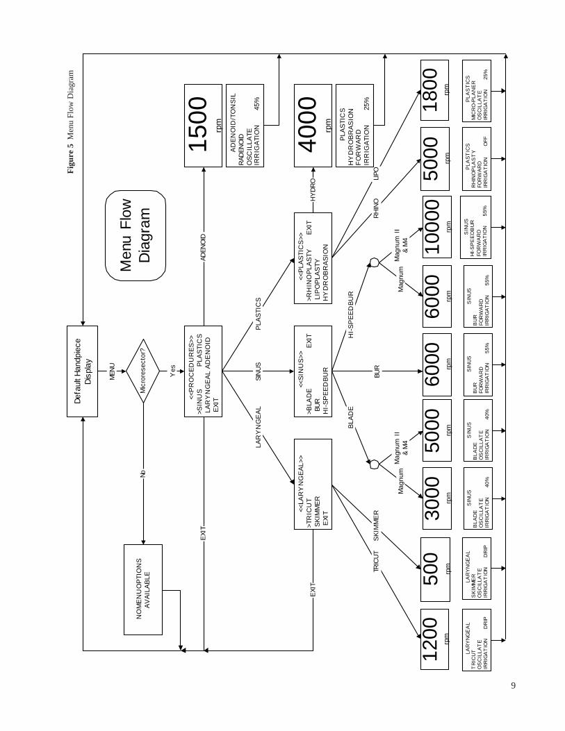
Figu
re 5
Men
u Fl
ow D
iagr
am

10
XPS® MULTIFUNCTION FOOTSWITCH, 1895400
The multifunction footswitch allows control of handpiece speed, rotation mode,and footswitch mode. The footswitch cable connects with the console by a pushconnector.
1. Right Pedal — The right pedal provides control of handpiece speed.When in the VARIABLE operating mode, handpiece speed increases asthe pedal is depressed. In the START/STOP operating mode, the hand-piece automatically operates at the MAX SET SPEED displayed on theconsole when the pedal is depressed. The right pedal also activates theirrigation pump if connected.
2. Left Pedal — Depressing and releasing the left pedal changes theROTATION direction (oscillate, forward, or reverse) of the handpiece.Note: Rotation mode may only be changed when the handpiece isnot running.
3. Top Button — Depressing and releasing this button changesthe FOOTSWITCH MODE (Variable or Start/Stop).
PRECAUTIONS
• DO NOT immerse the footswitch.• DO NOT sterilize the footswitch.
XPS® MULTIFUNCTION FOOTSWITCH, SINGLE PEDAL, 1895420
The multifunction footswitch allows control of handpiece speed, rotationmode, and footswitch mode. The footswitch cable connects with the consoleby a push connector.
1. Pedal — The pedal provides control of handpiece speed. When in theVARIABLE operating mode, handpiece speed increases as the pedal isdepressed. In the START/STOP operating mode, the handpieceautomatically operates at the MAX SET SPEED displayed on the con-sole when the pedal is depressed. The pedal also activates the irriga-tion pump if connected.
2. Left Button — Depressing and releasing this button changes theROTATION direction (oscillate, forward, or reverse) of the handpiece.Note: Rotation mode may only be changed when the handpiece isnot running.
3. Right Button — Depressing and releasing this button changes the FOOTSWITCH MODE (Variable or Start/Stop).
PRECAUTIONS
• DO NOT immerse the footswitch.• DO NOT sterilize the footswitch.
XPS® SINGLE FUNCTION
FOOTSWITCH, 1895410
The single function footswitch operates only in a variable mode. Itcontrols handpiece speed, which increases as the pedal is depressed.The pedal also activates the irrigation pump if connected. Thefootswitch cable connects with the console by a push connector.
3
21
Figure 7XPS® Single Function Footswitch,1895410
Figure 6-AXPS® Multifunction Footswitch,1895400
12
3
Figure 6-BXPS® Multifunction Footswitch,Single Pedal, 1895420
←
↑
→ 32
1

11
XPS® STRAIGHTSHOT® M4 AND MAGNUM® IIMICRODEBRIDER SYSTEM SET-UP AND USE
The StraightShot® M4 and Magnum® II Microdebrider Drill Systems are intended for use with the XPS® Model 3000Console, although they will operate with the XPS® 2000 Console. Likewise, the Straightshot® Magnum® will operatewith the XPS® 3000 Console. The StraightShot® M4 and Magnum® II default at 5,000 rpm oscillate and 6,000 rpmforward. The StraightShot® Magnum® defaults at 3,000 rpm oscillate and 6,000 rpm forward. However, theStraightShot® M4 and Magnum® II have top operating speeds of 5,000 rpm oscillate and 12,000 rpm in forward whilethe StraightShot® Magnum® has top operating speeds of 3,000 rpm oscillate and 6,000 rpm in forward. If theStraightShot® M4 and Magnum® II are connected to the XPS® 2000 Console they will operate at the same speeds asthe StraightShot® Magnum®. The multifunction or single function footswitches control the operating speeds of thehandpiece.
The StraightShot® M4 and Magnum® II Microdebrider Systems support a number of Otorhinolaryngology indica-tions listed under “Indications.” Many disposable blades and burs are available for this purpose. Additionally, theXPS® 3000 console offers a procedure setting screen which recommends and defaults to suggested operatingspeeds for each procedure. The default settings can be adjusted. Speed can be adjusted, within allowable ranges,using the top and bottom buttons in the control button cluster. Direction (forward and oscillate) can be adjustedusing the middle button. Pump flow rate for irrigation (bottom pump) is controlled with left and right buttons in thecontrol button cluster.
Pressing the “menu” button accesses procedure menus. After pressing the menu button, top, bottom, right, and leftbuttons control the cursor on the display. The center button acts as the select button.
The StraightShot® M4 and Magnum® II Microdebrider Systems consist of the following main components:
• XPS® Model 3000 Console with integrated irrigation pump.• StraightShot® M4 or Magnum® II Microdebrider Handpiece (to use the Image Guided capabilities of the
Image Guided version of this handpiece, refer to the following User’s Guides for your IGS system: LandmarX®
ENT Image Guidance Systems, Treon® ENT Image Guidance System with LandmarX® Software, LandmarXEvolution® ENT Image Guidance System, LandmarX Evolution® Plus ENT Image Guidance System, LandmarX®
Element System and iNav™ Element System ).• Footswitch• XPS® Microdebrider blades and burs.
BEFORE SURGERY
WARNINGS
• Refer to “Warnings Before Surgery” in the front section of this manual.
The following instructions are recommended for set-up and use of the StraightShot® M4 and Magnum® IIMicrodebrider Systems with the XPS® Model 3000 Console.
1. Inspect components for damage and determine if system is ready to use.2. On IV pole, mount XPS® Model 3000 console and plug unit into power source.3. Connect gray accessory cable (REF # 1895505) between Endo-Scrub® 2 and XPS® Model 3000 console if Endo-
Scrub® 2 is being used.4. On the rear of the console, turn the power switch to the ON position.5. With tubing set (REF # 1895522) purchased separately or included with straight XPS® blades, spike the irriga-
tion bag, then place and secure tubing set into the lower pump in console (top pump is intended for coolingdiscussed in drill set-up section).
6. Transferring sterilized StraightShot® M4 or Magnum® II handpiece plug/cord from scrub to circulator, plugStraightShot® M4 or Magnum® II into the large handpiece port on the XPS® 3000 console.

12
7. Connect footswitch into the XPS® Model 3000 and place under operating table.8. Place desired XPS® blade or bur in the StraightShot® M4 or Magnum® II collet mechanism as described in the
next section.9. Attach standard suction tubing to exhaust port of StraightShot® M4 or Magnum® II and to dedicated suction
canister.10. Clip irrigation tubing, suction tubing, and handpiece cable together with clips enclosed with XPS® blade
tubing set, or with StraightShot® M4. Clips are permanently attached to electrical cable.11. To prime the irrigation tubing, press and hold the right arrow key. The pump will run in Prime mode until
the right arrow key is released.12. After pump has been primed, set irrigation pump rate to desired setting.13. If handpiece speed other than default is desired, increase and decrease with top and bottom buttons.
DO NOT use burs above the speed indicated on the bur label.14. If direction other than oscillate is desired, change between forward and oscillate by using the center button.15. If suggested procedure settings are desired, press menu button, use top, bottom, left, and right buttons to
scroll through the menu to pick procedure and blade. Press center button to select an option. See menu flowdiagram, Figure 5.
The following set-up is recommended for the StraightShot® M4 and Magnum® II Microdebrider System:
StraightShot® toXPS® Irrigation TubingREF # 1895522
XPS® 3000 Console, One or Two PumpsREF # 1897101 or 1897102
XPS® Blade or Bur(see XPS® brochure for REF #)
Standard Operating RoomSuction Tubing Connected toDedicated Wall Suction
XPS® Footswitch (1895400 shown)REF # 1895400, 1895410, or 1895420
Power Cord Connected toStandard AC Wall Power
Figure 8 XPS® StraightShot® M4 and Magnum® II Microdebrider System
StraightShot® M4 HandpieceREF#1898200T (shown) orStraightShot® Magnum® IIHandpieceREF # 1897200, 1897201,or 1897200T
I.V. Pole
XPS® I.V. Pole Basket forFootswitch REF # 1897510

13
XPS® STRAIGHTSHOT® M4 AND MAGNUM® IIHANDPIECE ACCESSORIES
WARNINGS
• Use adequate irrigation from a separate user-provided irrigating source. The use of a bur without irrigation maycause an inordinate amount of heat buildup resulting in thermal injury to tissue.
• Disposable devices are for single-use only. Do not attempt to sterilize disposable devices. The disposables arepacked sterile and not intended for repeat use. To prevent contamination use only once.
• Use care in application of the moving cutting end to only appropriate anatomical landmarks and the intendedsurgical site when using XPS® accessories. The use of powered reciprocating/rotating instruments may result invibration-related injury. Use appropriate precautions.
• Employ visualization when using rotating XPS® accessories. Discontinue powered application in the event oflack of visualization of the surgical site.
• Use methods at the operative site to control bleeding that do not compromise patient safety during at-risksurgery.
• Always inspect the components before and after use for any damage. If damage is observed, do not use damagedpart until it is replaced. Damaged parts may deposit metal shavings on surgical site.
• Do not use any parts other than Medtronic Xomed, Inc. system components as damage or substandard perfor-mance could result.
• Remove and discard accessories following local regulations for proper disposal of contaminated materials.• Do not modify accessories used with the handpiece. Performance could be diminished with modified accessories.• Insertion of metal objects in blade or bur tip may cause the blade or bur to break leaving fragments in the wound.
The fragments may be difficult to remove, causing irritation, inflammation and foreign-body response at surgicalsite.
• Always keep the cutting tip of the accessory away from fingers and loose clothing. Prevent laceration of user andcross-contamination through compromised glove.
• Do not change accessory with handpiece running to prevent laceration of user and cross-contamination throughcompromised glove.
• Discontinue use of curved bur if tip begins to wobble and replace bur to prevent unintended tissue removal frompatient.
• Do not use accessory if package is opened or damaged. Broken seal offers no protection against cross-contami-nation.
• Bending or prying may break the accessory, causing harm to patient or staff.• Accessories are available for resection of soft tissue and bone for surgical procedures. Use of accessories
depends on the intended application and patient needs. Sharp-cutting powered accessories induce bleeding andremoval of significant tissue and bone.
• Insertion of metal objects in blade tip may cause the blade to break leaving fragments in the wound. Thefragments may be difficult to remove, causing irritation, inflammation and foreign-body response at surgical site.
• Use lock on StraightShot® M4 handpiece to prevent inadvertant rotation of blade or bur during use.• When precise location of the blade tip is required, engage the rotation lock on the handpiece, then calibrate and
verify the blade tip on the Image Guided Surgery (IGS) system. Always lock the StraightShot® M4 handpiecewhen driving non-rotatable blades to maintain their IGS calibration.

14
BLADE OR BUR INSTALLATION
1. Using thumb, depress the locking collar (A) on the frontof the handpiece.
2. Insert blade or bur with a slight rotating motion until bladeor bur is seated. For rotatable straight blades, orient theirrigation barb at the 3 o’clock position for right-handedsurgeons and 9 o’clock for left-handed surgeons. For ro-tatable curved blades, orient the irrigation barb at 3 o’clock.To fully seat an M4 rotatable blade, adjust the finger wheelwith small back-and-forth motions.
3. Align blade or bur tip opening to desired position.4. Release the locking collar.5. Pull on the blade or bur to ensure engagement and visually
check to make sure distal tip of inner blade is in contact with the distal tip of the outer cannula.6. For non-rotating blades, orient the blade or bur to desired position (usually 12 o’clock for the cutting surface and
6 o’clock for the irrigation barb) and locking mechanism (D).
TUBING ATTACHMENT
1. Adjust the clamp on the irrigation tubing to the off positionand spike the bag of irrigant.
2. Push the free end of the irrigation tubing onto the irrigationport on the blade (B) until tubing passes barb on the port andis secure.
3. Attach suction tubing securely to the suction port on thehandpiece (C).
4. Secure the suction and irrigation tubing to the handpiececable with the clip (if provided) and the white clamps in-cluded in the blade packaging.
XPS® STRAIGHTSHOT® M4 AND MAGNUM® II
SURGICAL PRECAUTIONS
• XPS® Blades should be operated in the oscillate mode only. Operating in the forward mode may cause damage tothe blade. XPS® burs should be operated in the forward mode only.
• Be sure the blade is fully engaged in the Microdebrider and verify the tip is fully engaged with the outer cannulaprior to use.
• To prevent damage to curved blades, disconnect suction tube prior to changing blade or bur during procedure.• The StraightShot® Magnum® II and StraightShot® M4 Microdebriders are intended to operate at speeds greater
than 6,000 rpm ONLY when used with the XPS® High Speed bur line.
AFigure 9 Blade or Bur Installation
Figure 10 Tubing Attachment
B
C
D

15
AFTER SURGERY
BLADE OR BUR REMOVAL1. If the irrigation pump is not used, turn off the irrigation flow using the roller clamp on the irrigation tubing.2. Remove and discard the tubing following local regulations for proper disposal of contaminated materials.3. Depress the locking collar of the handpiece and pull the blade or bur out of the handpiece and discard following
local regulations for proper disposal of contaminated materials.
Table. Using Wheel and Lock on StraighShot® M4 Handpiece linked to an Image Guided Surgery(IGS) System.
Location of tip must be knownduring procedure. Blade-windowTip Location
Non-Rotatable Blades,Including Laryngeal
M4 Rotatable Blades
1. Do not LOCK handpiece.2. Do not refer to IGS for
indication of location.3. Wheel is usable to vary tip
location.
1. Release blade from collet.2. Rotate blade into one of four
present orientations.3. Lock blade into collet.
1. Adjust blade tip to desiredlocation.
2. Activate LOCK.3. Mount IGS attachement to
handpiece using Allen wrench.4. Calibrate blade tip on IGS.5. Wheel is not usable.
1. Adjust blade tip to desiredlocation.
2. Mount IGS attachment tohandpiece using Allen wrench.
3. Calibrate blade tip on IGS.
Not applicable.
1. Do not LOCKhandpiece.
2. Mount IGSattachment othandpiece usingAllen wrench.
3. Calibrate blade tipon IGS.
4. Wheel is usable tovary windowlocation.
Variation preferred during procedure.

16Figure 11 Xcalibur® Hi-Torque Drill System
Xcalibur® Angled Hi-SpeedHandpiece Attachment REF # 3333755or Xcalibur® Angled Hi-Torque HandpieceAttachment REF # 3333750
Xcalibur® Hi-Torque Drill MotorREF # 3333850 (shown withangled handpiece attachment)
Irrigation Tubing Clips(irrigation tubing to cable,provided with irrigation tubing)
XPS® 3000 Console, One or Two PumpsREF # 1897101 or 1897102
Irrigation Tubing SetREF # 3318503
Medtronic XomedSurgical Bur(see Surgical BurCatalog for REF #)
XPS® Footswitch (1895400 shown) REF # 1895400, 1895410, or1895420
Power Cord Connected toStandard AC Wall Power
Lower Pumpfor Bur
Irrigation
Xcalibur® Straight Hi-Speed HandpieceAttachment REF # 3333705 or Xcalibur®
Straight Hi-Torque Handpiece AttachmentREF # 3333700
I.V. Pole
XPS® I.V. Pole Basket forFootswitch REF # 1897510
VISAO™ AND XCALIBUR® DRILL SYSTEMSET-UP AND USE
The Visao™ and Xcalibur® Hi-Speed Drills are used with the XPS® Model 3000 console with two integral pumps (one forhandpiece cooling, the other for irrigation). The Xcalibur® Hi-Torque Drill System is intended for use with the XPS® Model3000 Console, or the XPS® Model 2000 console and the optional XPS® Irrigator Pump, for the controlled dissection andremoval of bone during ENT surgery.Speed of the XPS® 3000 Drill System is set by use of the top and bottom buttons on the control button cluster on the console,and controlled by using the XPS® single function or multifunction footswitch. Rate of Irrigation is controlled by left and right(decrease and increase) buttons on the control button cluster.The Visao™ High-Speed Otologic Drill operates with Medtronic Xomed straight burs and Visao™ High Speed Curved Burs tomeet the needs of the surgeon, eliminating the need for handpiece attachments.The Xcalibur® drills have the ability to operate on the XPS® Model 3000 with interchangeable Hi-Speed water-cooled and Hi-Torque motors and straight or angled handpieces to meet the needs of the surgeon. Note that only the Xcalibur® Hi-SpeedStraight or Xcalibur® Angled Handpieces will fit onto the Xcalibur® Hi-Speed (Water-Cooled) Motor Assembly.
The Visao™ and Xcalibur® Drill’s bur notch mechanism incorporates Medtronic Xomed surgical burs of diameter .092 inches(2.34mm) that are at least 1.73 inches (44mm) long.
The XPS® 3000 Drill System is comprised of the following main components:
• XPS Model 3000 Console with Optional Coolant Pump• Footswitch• Either: Visao™ High-Speed Otologic Drill• Or: Xcalibur Hi-Speed and Hi-Torque Electric Motors,
Xcalibur Hi-Speed and Hi-Torque, Straight or Angled Handpiece Attachments.
The following set-up is recommended for the Hi-Torque Motor:

17
The following set-up is recommended for the Visao™ High Speed Otologic Drill (Water-Cooled) and Xcalibur®
Hi-Speed (Water-Cooled) Motor:
Irrigation Tubing SetREF # 3318503
Coolant Tubing Clips (coolant tubing& irrigation tubing to cable, providedwith coolant tubing)
Xcalibur® Hi-Speed Motor(Water-Cooled) REF# 3333840 (shown withstraight handpiece attachment)
Medtronic Xomed Surgical Bur (seeSurgical Bur Catalog for REF #)
XPS® Footswitch (1895400 shown)REF # 1895400, 1895410, or 1895420
Power Cord toStandard AC Wall Power
Hi- Speed Drill CoolantTubing Set REF # 3318506(with dual cannulatedspike and squeezable dripchamber)
Figure 12 Visao™ High-Speed Otologic Drill or Xcalibur® Hi-Speed Drill System
Lower Pumpfor Bur Irrigation
Straight Hi-Speed HandpieceAttachment REF # 3333705
(Xcalibur® only)
Angled Hi-Speed HandpieceAttachment REF # 3333755
(Xcalibur® only)
Top Pump forMotor Cooling
XPS® I.V. Pole Basket forFootswitch REF # 1897510
XPS® 3000 Console, TwoPumps REF # 1897102
I.V. Pole
Visao™ High-Speed OtologicDrill (Water-Cooled)REF # 3334800 &REF # 3334800T
Medtronic Xomed Surgical Bur(see Surgical Bur Catalog for REF #)

18
BEFORE SURGERY
WARNINGS
• Refer to “Warnings Before Surgery” in the front section of this manual.
The following instructions are recommended for set-up and use of the Visao™ High-Speed Otologic Drill, Xcalibur®
Hi-Speed (Water-Cooled) Drill system and/or the Xcalibur® Hi-Torque Drill System with the XPS® Model 3000:
1. Inspect components for damage and determine if system is ready to use.2. On IV pole, mount XPS® Model 3000 console and plug unit into power source.3. On the rear of the console, turn the power switch to the ON position.4. Plug the connector end of the motor cord into the XPS® Model 3000 console.5. Connect footswitch into XPS® Model 3000 console and place under operating table.6. If irrigation is desired, connect Irrigation Tubing (REF # 3318503) to irrigation port on Visao™ Irrigation Sleeve
(REF # 3334610) or, Visao™ Extended Bur Guard with Irrigation (REF # 3334635) or, Xcalibur® Irrigation Sleeve(REF # 3333610) or, Xcalibur® Hi-Speed Extended 75 mm Bur Guard with Irrigation (REF # 3333635) or, Xcalibur® Hi-Speed Extended 64 mm Bur Guard with Irrigation (REF # 3333655) or, Xcalibur® Hi-Torque Extended BurGuard with Irrigation (REF # 3333630). Spike irrigation bag and place the short piece of silicone tubing throughthe lower pump. Close pump head.
7. If the Visao™ High-Speed Otologic Drill (REF # 3334800 or REF # 3334800T) or Xcalibur® Hi-Speed, Water-Cooled, Motor Assembly (REF # 3333840) is used, attach each of the tubes from the Coolant Tubing (REF #3318506) to the ports on the handpiece. Spike a second large bag of irrigation fluid (sterile water, or saline ifsterile water is not available). Place the short piece of silicone tubing through the coolant pump (top pump onthe XPS® Model 3000 console).
8. Clip Irrigation Tubing to Visao™ motor cable clips or Xcalibur® motor cable using clips provided with tubing set.9. If the Visao™ Drill is used, both the irrigation tubing and coolant tubing can be retained in the clips on the
handpiee cable. If the Hi-speed (Water-Cooled) motor is used, clip Hi-Speed Coolant Tubing and IrrigationTubing (if used) to Xcalibur® Motor Cable using clips provided with the tubing set. (The clips in the IrrigationTubing will not be needed.)
10. To prime the irrigation tubing, press and hold the right arrow key. The pump will run in Prime mode until theright arrow key is released. This function runs simultaneously with the coolant pump.
11. To prime the coolant pump, press and hold the right arrow key. The pump will run in Prime mode until the rightarrow key is released. This function runs simultaneously with the irrigation pump. Alternatively, ensure the
handpiece bur lock is closed (align small dots on handpiece), then depress the foot pedal momentarily (1-2seconds). After the foot pedal is released, the cooling pump will continue to run for approximately one minute.Continue to prime the cooling system until all bubbles are removed.
12. Select drill speed settings by depressing the top or bottom buttons (increase and decrease speed) in the controlbutton cluster.
13. Unlock the Visao™ or Xcalibur® Drill handpiece collet by rotating lock ring ¼ turn, insert desired bur (rotatingto engage the base of the bur completely into position in the handpiece), then rotate the lock ring ¼ turn backto lock the bur into the handpiece (aligning the small dots on the handpiece).
14. Always tug bur for security. Repeat step 13 if necessary.15. IMPORTANT: Test drill by depressing foot pedal prior to use. The system is now ready to use. Note that the
cooling pump will continue to run for about one (1) minute after your foot is removed from the foot pedal.

19
VISAO™ AND XCALIBUR® BUR INSTALLATION AND TUBINGATTACHMENT
WARNINGS• Do not change accessory with handpiece running to prevent laceration of user and cross-contamination through
compromised glove.• Do not use burs above the speed indicated on the bur label. Exceeding speed may cause the burs to break.• Carefully inspect burs prior to and following each use for excessive wear, fragmentation, eccentricities or other
defects. Do not use dull, damanged or bent burs. Use of dull burs can reduce the handpiece effectiveness andcause the handpiece temperature to increase.
• Do not attempt to resharpen used burs. Worn burs should be replaced with new ones frequently to ensureeffective cutting and control of the drill.
• Excessive pressure applied to bur may cause bur fracture. Should a bur fracture during use, extreme care must beexercised to ensure that all fragments of the bur are retrieved and removed from the patient. Unremoved burfragments may cause tissue damage to the patient.
• Test for bur wobble (eccentricity) at desired speed prior to use. Use a bur guard (Xcalibur® only) if needed. Selecta new bur or reduce speed if wobble is observed.
• Test for bur wobble (eccentricity) at the desired speed prior to use. Select a new bur or reduce speed if wobble isobserved. Eccentricity of the bur can cause bur vibration and may result in excessive tissue and bone destructionand hearing damage. Always examine the operation of each bur in the handpiece before each use. Operatingcertain burs at high speed can cause vibration of the bur.
Visao™ High-Speed Curved Burs Only• Keep the cooling sleeve irrigated to prevent thermal injury to tissue.• During procedures near nerves, keep bur and bur cannula away from tissue to minimize the potential for thermal
injury.• For procedures near nerves, nerve monitoring should be used to alert the user of the potential for injury.
BUR ATTACHMENT1. Using thumb and index finger, twist handpiece locking mechanism counter clockwise to unlock handpiece.2. Insert desired Medtronic Xomed Surgical Bur into handpiece, giving bur a ¼ turn as it is seated
(or until it seats fully into the handpiece).3. Lock and secure bur by twisting handpiece locking mechanism clockwise.4. Tug on bur to ensure bur is secured and locked into the handpiece.
CURVED BUR INSTALLATION (VISAO™ HIGH SPEED CURVED BURS ONLY)1. Using thumb and index finger, twist the handpiece locking collar to the unlocked position.2. Insert the curved bur onto the nose of the handpiece loosely and rotate the curved bur to the desired angular
position.3. Firmly push the curved bur hub onto the handpiece until it snaps in place. Gently twist the curved bur hub back
and forth to ensure it is completely seated in the angular detents.4. Using thumb and index finger, twist the handpiece locking collar to the locked position.5. Push the bur head into the handpiece until it snaps in place.6. Gently tug on the bur head to ensure it is locked in place.
TUBING ATTACHMENT - IRRIGATION1. During initial set-up, ensure drill irrigation tubing is clipped into place along the motor electrical cable using clips
provided with tubing set.2. Insert tubing from the Visao™ or Xcalibur® Drill handpiece on to the Visao™ Irrigation Sleeve (REF # 3334610) or,
the Visao™ Extended Bur Guard with Irrigation (REF # 3334635) or, Xcalibur® Irrigation Sleeve Assembly (REF #3333610) or, Xcalibur® Hi-Speed Extended 75 mm Bur Guard with Irrigation (REF # 3333635) or, Xcalibur® Hi-SpeedExtended 64 mm Bur Guard with Irrigation (REF # 3333655) or, Xcalibur® Hi-Torque Extended Bur Guard withIrrigation (REF # 3333630).
3. Rotate the irrigation sleeve to the desired surgeon position.4. Spike the irrigation bag.5. Install the tubing into the pump.6. Prime the tubing set.7. Test tubing flow and set-up by depressing footswitch.

20
TUBING ATTACHMENT - COOLING (WATER-COOLED MOTOR)1. During initial set-up, ensure water-cooled drill coolant tubing is clipped into place along the motor electrical cable.
For Xcalibur®, use clips provided with tubing set. (The irrigation tubing, if used, can be attached using these sameclips, and the clips in the irrigation tubing set will not be needed.)
2. Connect tubing set to the cooling ports of the water-cooled motor.3. Spike a large bag of irrigation fluid (preferably sterile water, but saline may be used).4. Place the short section of silicone tubing through the cooling pump (upper pump).5. Prime the cooling tubing set while squeezing drip chamber a few times. Continue to prime until air bubbles no
longer occur at the coolant bag. IMPORTANT: Ensure all air is purged out of the motor. Roll the motor back andforth during priming to encourage air out of the motor’s cooling jacket.
VISAO™ AND XCALIBUR® SURGICAL PRECAUTIONS
• Always ensure that the bur is securely engaged into the handpiece prior to operating the system.• When operating or testing the Poweforma®, Xcalibur® and Visao™ drill handpieces, ensure the bur is properly
inserted and locked into the handpiece. Running the drill with the collet unlocked can damage the lockingmechanism.
• Improper priming of the Xcalibur® and Visao™ High-Speed Drills will result in excessive handpiece temperature.• The Visao™ and Xcalibur® Hi-Speed Water-Cooled Drills work only with the XPS® 3000. Use without water-bag
will damage the motor in the handpiece.• IMPORTANT: Always examine operation of each bur in a handpiece before each use. Operating certain burs at
high speeds can cause vibration of the bur. The following are suggestions for reducing bur vibration:
> Reduce handpiece operating speed.> Use only burs that are rated for High Speed operation.> Use Visao™ Extended Bur Guards (REF # 3334625 or 3334635) with 64 mm or 75 mm burs in the Visao™ High-
Speed Otologic Drill.> Use Xcalibur® Hi-Speed Extended 64 mm Bur Guards (REF # 3333645 or 3333655) with 64 mm burs in the
Xcalibur® Hi-Speed Drill.> Use Xcalibur® Hi-Speed Extended 75 mm Bur Guards (REF # 3333625 or 3333635) with 75 mm burs in the
Xcalibur® Hi-Speed Drill.> Use Xcalibur® Hi-Torque Extended Bur Guards (REF # 3333620 or 3333630) with 75 mm burs in the Xcalibur®
Hi-Torque Drill.> Operate handpiece at 50% speed when using burs 75 mm or longer.> Select a new bur.
21
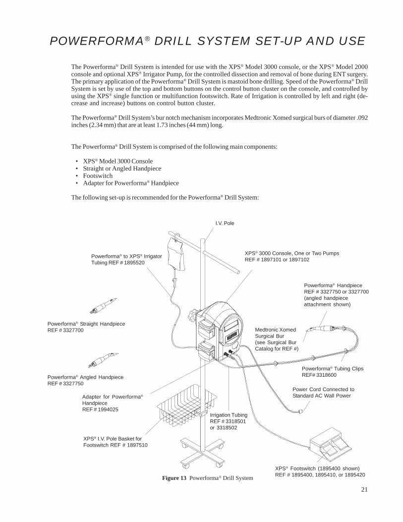
POWERFORMA® DRILL SYSTEM SET-UP AND USE
The Powerforma® Drill System is intended for use with the XPS® Model 3000 console, or the XPS® Model 2000console and optional XPS® Irrigator Pump, for the controlled dissection and removal of bone during ENT surgery.The primary application of the Powerforma® Drill System is mastoid bone drilling. Speed of the Powerforma® DrillSystem is set by use of the top and bottom buttons on the control button cluster on the console, and controlled byusing the XPS® single function or multifunction footswitch. Rate of Irrigation is controlled by left and right (de-crease and increase) buttons on control button cluster.
The Powerforma® Drill System’s bur notch mechanism incorporates Medtronic Xomed surgical burs of diameter .092inches (2.34 mm) that are at least 1.73 inches (44 mm) long.
The Powerforma® Drill System is comprised of the following main components:
• XPS® Model 3000 Console• Straight or Angled Handpiece• Footswitch• Adapter for Powerforma® Handpiece
The following set-up is recommended for the Powerforma® Drill System:
Figure 13 Powerforma® Drill System
XPS® 3000 Console, One or Two PumpsREF # 1897101 or 1897102
Powerforma® to XPS® IrrigatorTubing REF # 1895520
Irrigation TubingREF # 3318501or 3318502
Powerforma® Straight HandpieceREF # 3327700
Powerforma® Angled HandpieceREF # 3327750
Medtronic XomedSurgical Bur(see Surgical BurCatalog for REF #)
Powerforma® HandpieceREF # 3327750 or 3327700(angled handpieceattachment shown)
Powerforma® Tubing ClipsREF# 3318600
Power Cord Connected toStandard AC Wall Power
XPS® Footswitch (1895400 shown)REF # 1895400, 1895410, or 1895420
Adapter for Powerforma®
HandpieceREF # 1994025
I.V. Pole
XPS® I.V. Pole Basket forFootswitch REF # 1897510

22
BEFORE SURGERY
WARNINGS
• Refer to “Warnings Before Surgery” in the front section of this manual.
The following instructions are recommended for set-up and use of the Powerforma® Drill System with XPS® Model3000:
1. Inspect components for damage and determine if system is ready to use.
2. On IV pole, mount XPS® Model 3000 console and plug unit into power source.
3. On the rear of the console, turn the power switch to the ON position.
4. Attach the XPS® to Powerforma® Tubing (REF # 1895520) to the Powerforma® Irrigation Tubing (REF # 3318501)which should already be attached to the Powerforma® Handpiece.
5. Clip the Powerforma® Irrigation Tubing (REF # 3318501) along the handpiece electrical cord with Powerforma®
Tubing Clips (REF # 3318600).
6. Transfer the connector end of the handpiece electrical cable, along with the irrigation tubing, to the circulatingnurse. Be careful to maintain sterility.
7. Spike the irrigation bag and place the XPS® to Powerforma® Tubing (REF # 1895520) through the lower pump.Close the pump head.
8. Connect footswitch into XPS® Model 3000 console and place under operating table.
9. To prime the irrigation tubing, press and hold the right arrow key. The pump will run in Prime mode until theright arrow key is released.
10. After tubing has been primed, set irrigation pump rate to desired setting.
11. Select drill speed settings by depressing the top or bottom buttons (increase and decrease speed) in the controlbutton cluster.
12. To insert a bur, pull back on the bur release button with your thumb, and slide the bur shaft into the handpiecechuck. Twist the bur a quarter-turn (1/4) or until it slides fully into place. Allow the bur release button to slideforward, which locks the bur into place.
13. Always tug bur to ensure it is securely locked in place. Repeat step 12 if necessary.
14. Test drill by depressing foot pedal. The system is now ready to use.
15. To remove the bur, pull back on the bur release button, and pull the bur out of the chuck.

23
POWERFORMA® BUR INSTALLATION AND TUBING ATTACHMENT
WARNINGS
• Ensure bur is properly secured in the Powerforma® handpiece prior to surgeon activation.• DO NOT change burs with handpiece running.• Use adequate irrigation. The use of a bur without irrigation may cause an inordinate amount of heat build-up
resulting in thermal injury to tissue.• Test for bur wobble (eccentricity) at desired speed prior to use. Select a new bur or reduce speed if wobble is
observed.• Excessive pressure applied to bur may cause bur fracture which may cause injury.• DO NOT use dull, damaged, or bent burs. Change burs frequently for optimal performance. Use of dull burs can
reduce handpiece cutting effectiveness and cause handpiece temperature to increase.
BUR ATTACHMENT1. Using your thumb, pull back on the bur release button.2. Insert desired Medtronic Xomed surgical bur into handpiece, giving bur a 1/4 turn as it is seated
(or until it seats fully into the handpiece).3. Allow the bur release button to slide forward.4. Tug on bur to ensure bur is secured and locked into the handpiece.
TUBING ATTACHMENT - IRRIGATION1. During initial set-up, ensure drill irrigation tubing is clipped into place on drill using clips provided with tubing
set.2. Connect tubing set from the Powerforma® Drill handpiece into XPS® Powerforma® tubing set (REF # 1895520).3. Install XPS® to Powerforma® tubing set (REF # 1895520) into the lower pump. Close the pump head.4. Prime the tubing set.5. Test tubing flow and set-up by depressing footswitch.
POWERFORMA® SURGICAL PRECAUTIONS
• Excessive noise from the bur when drilling close to the cochlea or ossicular chain may cause hearing damage.• Excessive force may lead to bur bending, breakage or excess vibration. If the bur fractures during use, the
resultant sharp surfaces may cause lacerations of the body tissue. A bur which fractures inside a patient may alsocause tissue injury and necessitate emergency procedures for extraction.
• Eccentricity of the bur can cause bur vibration and may result in excess tissue and bone destruction and hearingdamage.
• When operating or testing the Powerforma® drill handpiece, ensure bur is properly inserted into the handpiece.Running the handpiece with an unsecured bur can cause damage. Running a handpiece without a bur is notrecommended.
• During procedures, operating room technicians and nurses should always check bur function, fit, tightness, andsecurity in the handpiece before handing off to surgeon for use.
• Always examine operation of each bur in a handpiece before each use. Operating certain burs at high speeds cancause vibration of the bur. The following are suggestions for reducing bur vibration:
> Reduce handpiece operating speed.> Operate handpiece at 50% speed when using burs 75 mm or longer.> Select a new bur.

24
SKEETER® ULTRA-LITE OTO-TOOL SYSTEMSET-UP AND USE
The Skeeter® Ultra-Lite Oto-Tool System is a slender, lightweight drill handpiece with burs, specifically used inmiddle ear surgical procedures, including stapes footplate surgery. The Skeeter® handpiece and burs may be usedwith the XPS® Model 3000 via direct connection with the Skeeter® handpiece connector. The lightweight Skeeter®
Ultra-Lite Oto-Tool Handpiece weighs 57 grams. The drill shaft diameter is approximately 2mm and is angledapproximately 15 degrees from the plane of the handpiece. The shaft angulation and small diameter maximizevisualization of the surgical field during drill use.
The Skeeter® Ultra-lite Oto-Tool Handpiece can be powered by three (3) 9 volt batteries housed in the AcceleratorFoot Control. However, when used with the XPS® Model 3000 console, the handpiece plugs directly into theconsole and is operated using the XPS® single function or multifunction footswitch. The footswitch allows variablespeed operation of the handpieces ranging from very slow to high speed in excess of 12,000 rpm.
The Skeeter® is used with the Oto-Flex bur. The Oto-Flex bur designed for use with the Skeeter® are composed of aflexible stainless steel shaft with a bur and a PTFE bearing at one end and the handpiece engagement at the other.The inside of the PTFE bearing is lightly coated with silicone spray to reduce operating friction.
COLOR CODINGFor ease of identification of size, all Oto-Flex Burs are color coded. Diamond Burs are further differentiated fromCarbide Burs by a white band on the shaft of each Diamond Bur. A Color Code Chart is conveniently provided in thebase of the Oto-Tool System Sterilization Case. The bur size identification color code is as follows:
Violet: 0.5 mm Yellow: 0.8 mm Brown: 1.8 mmBlue: 0.6 mm Orange: 1.0 mm Red: 2.3 mmGreen: 0.7 mm Gray: 1.4 mm Black: Specialty
For a complete listing of Skeeter Ultra-Lite Oto-Tool System, consult the “System Component and Accessories”section of the Skeeter User’s Guide (68E1279).
The Skeeter® Ultra-Lite Oto-Tool System consists of the following main components:
• XPS® Model 3000 Console• Skeeter® Ultra-Lite Oto-Tool Handpiece• Footswitch• Oto-Flex burs
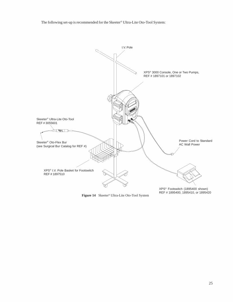
25
XPS® 3000 Console, One or Two Pumps,REF # 1897101 or 1897102
Power Cord to StandardAC Wall Power
Skeeter® Oto-Flex Bur
(see Surgical Bur Catalog for REF #)
Skeeter® Ultra-Lite Oto-Tool
REF # 3055601
XPS® Footswitch (1895400 shown)REF # 1895400, 1895410, or 1895420
Figure 14 Skeeter® Ultra-Lite Oto-Tool System
The following set-up is recommended for the Skeeter® Ultra-Lite Oto-Tool System:
I.V. Pole
XPS® I.V. Pole Basket for FootswitchREF # 1897510
26
BEFORE SURGERY
WARNINGS• Refer to “Warnings Before Surgery” in the front section of this manual.• DO NOT attempt to resharpen used burs. Worn burs should be replaced with new ones frequently to ensure
effective cutting and control of the drill.• Carefully inspect burs both prior to and following each use for signs of excessive wear, fragmentation, eccen-
tricities or other defects. Replace any suspicious bur with a new one prior to use.• Should a bur fracture in use, extreme care must be exercised to ensure that all fragments of the bur are retrieved
and removed from the patient. Unremoved bur fragments may cause tissue damage to the patient.
PRECAUTIONS• Always handle handpieces with care to avoid damage.• Make certain the appropriate bur is securely fastened into the handpiece prior to use. USE ONLY MEDTRONIC
XOMED ROTARY BURS INTENDED FOR USE WITH THE SKEETER® ULTRA-LITE OTO-TOOL.• Excessive noise from the bur when drilling close to the cochlea or ossicular chain may cause hearing damage.• Excessive force may lead to bur bending, breakage or excess vibration. If the bur fractures during use, the
resultant sharp surfaces may cause lacerations of the body tissue. A bur which fractures inside a patient mayalso cause tissue injury and necessitate emergency procedures for extraction.
• Eccentricity of the bur can cause bur vibration and may result in excess tissue and bone destruction andhearing damage.
• DO NOT attempt to bend needle nose or effect repairs to the system.
The following instructions are recommended set-up and use of the Skeeter® Ultra-Lite Oto-Tool with the XPS® 3000:
1. Inspect components for damage and determine if system is ready to use.2. On IV pole, mount XPS® Model 3000 console and plug unit into power source.3. On the rear of the console, turn the power switch to the ON position.4. After removal of the handpiece from the sterilization tray, transfer the connector from the sterile field to the
circulating nurse.5. The cable is plugged into the appropriate (smallest) connector in the console.6. Connect footswitch into XPS® Model 3000 console and place under operating table.7. Load the desired bur for the procedure into the handpiece by inserting the bur shaft through the distal end of
the handpiece with a slight twisting motion while simultaneously depressing the bur release button. The bur islocked into place when a “click” is noted. Locking of the bur should be checked prior to use by firmly pullingon the bur after the “click” is noted. To remove the bur from the handpiece, depress the Bur Release Button onthe handpiece and carefully pull the bur out.
8. Select drill speed settings by depressing the top and bottom buttons (increase and decrease speed) in thecontrol button cluster.
9. Tug the bur to ensure its security in the handpiece.10. Test drill by depressing foot pedal. The system is now ready to use.

27
CLEANING AND STERILIZATION GUIDELINES
The following cycles are compatible with the each handpiece as listed below; however, it is the responsibility ofeach health care facility to validate the sterilization process with their particular equipment and procedures toassure sterility.
PRECAUTION
• DO NOT cold soak sterilize the handpiece in glutaraldehyde. This will void the Warranty.
WARNINGS• Disconnect power before cleaning the unit.• Inspect components for any damage before and after each use. If you see damage, do not use the system until it
is repaired.• After cleaning and sterilization, verify functionality by operating the equipment prior to the surgical procedure.
AFTER SURGERY
XPS® 3000 Console• DO NOT immerse the console.• Turn the power off and unplug console before cleaning.
Footswitches• DO NOT immerse the footswitch.
XPS® StraightShot® M4, StraightShot® Magnum® II and StraightShot® Magnum® Handpieces• DO NOT immerse the handpieces.• Remove and discard the tubing and blade/bur following local regulations for proper disposal of
contaminated materials.
Visao™ High-Speed Otologic Drill• DO NOT immerse the handpiece.• Remove bur from handpiece prior to cleaning.
Xcalibur® Hi-Torque Handpiece• DO NOT immerse the handpiece attachments or the motor assembly.• Remove bur from handpiece prior to cleaning.• DO NOT insert cleaning plug in the front of the motor assembly before sterilization.• DO insert cleaning plug in the front of the motor assembly before cleaning.
Xcalibur® Hi-Speed Handpiece• DO NOT immerse the handpiece attachments or the motor assembly.• Remove bur from handpiece prior to cleaning.• DO NOT insert cleaning plug in the front of the motor assembly before sterilization.• DO insert cleaning plug in the front of the motor assembly before cleaning.
Powerforma® Handpiece• Remove bur from handpiece prior to cleaning.• DO NOT immerse the handpiece.
Skeeter® Handpiece• Remove bur from handpiece prior to cleaning.• DO NOT immerse the handpiece.
Oto-Flex Burs• DO NOT immerse the burs.

28
AFTER SURGERY (continued)
XPS Disposable Blades and Burs• If the irrigation pump is not used, turn off the irrigation flow using the roller clamp on the irrigation tubing.• Remove and discard the tubing following local regulations for proper disposal of contaminated materials.• Depress the locking collar of the handpiece and pull the blade or bur out of the handpiece and discard following
local regulations for proper disposal of contaminated materials.
Medtronic Xomed Reusable Burs for Mastoid Drilling• Initiate cleaning immediately after surgery (see cleaning section).
CLEANING
The following cycles are compatible with the each handpiece as listed below; however, it is the responsibility ofeach health care facility to validate the sterilization process with their particular equipment and procedures toassure sterility.
PRECAUTIONS• DO NOT use organic solvents such as acetone or isopropyl alcohol to clean the bur chuck.• USE ONLY an enzymatic detergent and distilled water for cleaning after every case or as required.• DO NOT clean the handpieces in an ultrasonic cleaner or allow them to be fully immersed in any soaking
solution. These procedures may result in damaging the handpieces beyond repair.
XPS ®3000 Console• Wipe down the console with standard disinfectant.• Dry the console with a clean, non-abrasive cloth. Wipe dry before storing.• Be sure to dry off the console after cleaning. Moisture inside the console could cause damage.
Footswitches• DO NOT immerse the footswitch.• Clean the outside of the footswitch by wiping with standard disinfectant.
XPS® StraightShot® M4, StraightShot® Magnum® II and StraightShot® Magnum® Handpieces• DO NOT immerse the handpiece.• Wipe the handpiece and cable with disinfectant applied to a clean, non-abrasive cloth.• Gently clean the handpiece with a moistened soft bristle brush or pipe cleaner, making sure to clean all pas-
sages. Use an enzymatic detergent solution to loosen and remove collected tissues from the unit.• Hold the handpiece with the front end pointed downward during rinsing.• Dry the handpiece and cable with a lint-free towel. Make sure to dry off the electrical connection on the cable
ends.• Apply a small amount of silicone spray into front-end collet and outside of handpiece.
Wipe dry before storing.• Sterilize the handpieces immediately after cleaning.
Visao™ High-Speed Otologic Drill, Irrigation Sleeves, and Bur Guards• DO NOT immerse the handpiece.• After surgery, clean the irrigation sleeves and bur guards with an enzymatic detergent solution. Wipe the
handpiece and cable with disinfectant applied to a clean, non-abrasive cloth.• A chuck brush cleaner (REF# 3112500) or an appropriately sized small (plastic bristle) bore brush may be
inserted into the distal end of the Visao™ handpiece, irrigation sleeves and bur guards to assist in removingfluids, tissue, or bone fragments.
• Rinse out the distal end of the handpiece. Shake excess water from the handpiece.• Ensure all water is drained from the cooling housing. If saline was used for cooling during surgery, use distilled
water to rinse the housing prior to draining.• Using distilled water, rinse saline from the irrigation nozzles. Drain the nozzle of all water.• Sterilize the handpiece, irrigation sleeves, and bur guards immediately after cleaning.

29
CLEANING (continued)
Xcalibur® Hi-Torque and Hi-Speed Straight and Angled Handpiece Attachments, IrrigationSleeves, and Bur Guards
• DO NOT immerse the straight and angled handpiece attachments.• After surgery, clean the irrigation sleeves and bur guards with an enzymatic detergent solution. Wipe the
straight and angled handpiece attachments with disinfectant applied to a clean non-abrasive cloth.• A chuck brush cleaner (REF# 3112500) or an appropriately sized small (plastic bristle) bore brush may be
inserted into the distal end of the Xcalibur® handpiece attachments, irrigation sleeves and bur guards to assistin removing fluids, tissue, or bone fragments.
• Rinse out the distal end of the handpiece. Shake excess water from the handpiece attachments.• Using distilled water, rinse saline from the irrigation nozzles. Drain the nozzle of all water.• Sterilize the handpiece, irrigation sleeves, and bur guards immediately after cleaning.
Xcalibur® Hi-Torque Motor• DO NOT immerse the motor assembly.• Ensure that the cleaning plug is inserted into the front of the motor assembly.• After surgery, wipe down motor cables and motor housing with disinfectant.• If using a dishwasher, place handpiece in a vertical position (motor up) to allow water drainage.• Sterilize the motor assembly immediately after cleaning.
Xcalibur® Hi-Speed Motor• DO NOT immerse the motor assembly.• Ensure that the cleaning plug is inserted into the front of the motor assembly.• After surgery, wipe down motor cables and motor housing with disinfectant.• Ensure all water is drained from the motors cooling housing. If saline was used for cooling during surgery, use
distilled water to rinse the housing prior to draining.• If using a dishwasher, place handpiece in a vertical position (motor up) to allow water drainage.• Sterilize the motor assembly immediately after cleaning.
Powerforma® Handpiece• DO NOT immerse the handpiece.• IMPORTANT NOTE: These procedures are critical to continued optimal performance. O.R. Personnel
should be familiar with the cleaning solutions and should use them routinely each time the handpiece isused.
CLEANING CAUTIONS• Always hold the handpiece with the nose pointing down to prevent any moisture from
reaching the motor.• If using a dishwasher, place handpiece in a vertical position (motor up) to allow water drainage.• DO NOT LUBRICATE, SOAK, WASH OR SUBMERGE the handpiece in detergent or any solution.• Always keep the handpiece as dry as possible to prevent corrosion, especially during sterilization and stor-
age.CLEANING HANDPIECE BUR CHUCK• Set the maximum speed to the 25% setting.• CAUTION: Cleaning at speeds over 25% may damage handpiece.• Remove the bur and insert only the nose of the handpiece into 1 oz. of an enzymatic detergent solution.• Run the handpiece for approximately 30 seconds.• Rinse the bur chuck by running the handpiece in distilled water for approximately 30 seconds.• Dry the inside of the bur chuck with a chuck brush (pipe cleaner, REF # 3112500).• Wipe off the handpiece with disinfectant and a soft cloth to remove blood and particles.• Cover the nose of the handpiece with the nose protector. This attachment shields the chuck and irrigation tip.• Sterilize the handpieces immediately after cleaning.CLEANING TUBING• Using distilled water, flush saline from reusable tubing and the tubing that runs through the handpiece. Clear
the tubing of all water by running in the pump until all water is removed. Autoclave the reusable tubing alongwith the handpiece.
• Sterilize the tubing, along with the handpiece, immediately after cleaning.OR
• If using disposable tubing, flush the portion of tubing that runs through the handpiece, and clear it of all water.Then discard the disposable tubing.
• Use a fresh tubing set for the next surgical procedure.
30
CLEANING (continued)
Skeeter® Handpiece• The handpiece may be cleaned and carefully rinsed with an enzymatic detergent. DO NOT FULLY IMMERSE
OR ULTRASONICALLY CLEAN THIS INSTRUMENT. The cannulated needle nose should be cleaned aftereach use and prior to sterilization by immersing the distal end of the handpiece in an enzymatic detergentsolution to the level of the Bur Release Button. DO NOT USE ANY CLEANING INSTRUMENTS IN THECANNULATED SHAFT OF THE HANDPIECE.
• To remove occasional residual buildup on handpiece cable connector, use a soft brush and isopropyl alcohol.Rinsing:
• Immerse the distal end of the handpiece in distilled water up to the Bur Release Button and use a gentle swirlingmotion to flush away residual cleaning solution. Avoid water accumulation in the motor housing by shakingexcess water droplets out with a downward motion.
Lubrication:• Silicone spray should be sprayed into the cannulated shaft of the handpiece prior to sterilization. Apply
silicone spray until surplus silicone lubricant is noted on the outside of the Bur Release Button. Wipe awayexcess lubricant from the handpiece. Following this procedure will insure that the bur release mechanism is welllubricated for proper functioning.
• Sterilize the handpieces immediately after cleaning.
Oto-Flex BursCleaning:• The Skeeter® Ultra-Lite Oto-Tool Systems accepts Oto-Flex Burs. All Oto-Flex Burs may be cleaned either by
using an enzymatic detergent or by ultrasonic means. Rinse with distilled water to remove cleaning solutionresidues and allow burs to dry. Following cleaning, apply a light coating of silicone spray in the followingmanner: grasp the PTFE bearing and rotate the bur to assure application of the silicone spray inside the bearing.
Maintenance:• During routine use normal wear may become evident on the bur and bur shaft. Examine burs under magnifica-
tion for evidence of wear following each cleaning. Minor bowing of the bur shaft may be straightened by usingthe fingers to rub and pull on the small shaft. Care should be exercised not to crimp or bend the small shaftduring handling or when straightening the shaft. Frequent replacement of burs is recommended to assureoptimum cutting performance and PTFE bearing concentricity. Burs exhibiting the following conditions shouldbe replaced: 1) nicks on cutting surfaces, 2) noticeable wear on PTFE bearings, 3) severe bends or crimps on burshaft, or 4) bur not running concentrically.
XPS® Disposable Blades and Burs• Do Not reuse. Remove and discard following local regulations for proper disposal of contaminated
materials.
Medtronic Xomed Reusable Burs for Mastoid DrillingCAUTION• Burs should be removed from the handpiece for sterilization and drying.• Monitor bur edges by viewing under microscope or magnifying glass. Dull burs increase pressure on the
handpiece. The motor may overheat and be damaged if continually overloaded.Cleaning:1. Promptly and thoroughly rinse burs with deionized water after each use.2. Soak in lukewarm*, mild* enzymatic detergent, and deionized water for a minimum of two minutes. Clean
ultrasonically in a lukewarm* solution of mild* detergent and deionized water for at least 30 seconds. Rinsethoroughly with deionized water and wipe dry.(*less than 43°C; pH 7.0 - 8.5)
Additional cleaning methods:•. Presoaking in 3% hydrogen peroxide.•. Additional thorough scrubbing of burs with a soft instrument brush while submerged in cleaning solution may
be warranted to remove blood and tissue.

31
STERILIZATION
The following cycles are compatible with the each handpiece as listed below; however, it is the responsibility ofeach health care facility to validate the sterilization process with their particular equipment and procedures toassure sterility.
WARNINGS• DO NOT modify accessories used with any handpiece.• Insertion of metal objects in blade or bur window may cause the blade or bur to break leaving fragments in the
wound which may be difficult to remove.• Bending or prying may break the blade or bur, causing harm to patient or staff.
PRECAUTIONS• DO NOT immerse the handpieces, as damage may result.• After sterilizing, check electrical connectors for moisture. If moisture is present do not operate, as damage may
result. Do not operate or store the handpiece unless a drying cycle has been performed.• DO NOT cold soak sterilize the handpiece in glutaraldehyde. This will void the warranty.• Regardless of which type of steam sterilization is used, it is important that all electrical connectors of the hand-
piece be free of any moisture in the internal connection features. Damage may result to the instrument if it isoperated with moisture in the electrical connectors. Do not operate or store the handpiece unless a drying cyclehas been performed.
• Remove the handpiece from the sterilizer immediately after the sterilization cycle is complete.• Increase temperatures higher than those stated when necessary to satisfy governmental or health care facility
requirements so long as the temperature does not exceed 149° C (300° F). Heating above 149° C (300° F) maydamage the handpiece and will void the warranty.
• DO NOT use organic solvents such as acetone or isopropyl alcohol to clean the bur chuck.• Use only a mildly alkaline, low-sudsing detergent (Medtronic Xomed Cleaning Solution is recommended) and
distilled water for cleaning after every case or as required.• Remove the bur from the Drill handpieces before sterilization.• Store in a clean dry place.• DO NOT clean handpieces in ultrasonic cleaner or allow them to be fully immersed in any soaking solution.
These procedures my result in damaging the handpieces beyond repair.• DO NOT attempt to bend needle nose or effect repairs to either system.• Remove the bur from the handpiece before sterilization.• Sterilize immediately after cleaning. DO NOT STORE UNLESS A DRYING CYCLE HAS BEEN PERFORMED.• Always wrap the electrical cord carefully inside the sterilizer tray during sterilization to prevent damage to the
cord when closing the tray lid.• Regardless of which type of steam sterilization is used, it is extremely important that the handpiece is rapidly and
completely dried before it is stored. If a vacuum drying cycle is not used following steam sterilization, moisturemay be trapped within the handpiece causing corrosion and residue deposits, resulting in premature wear and areduction in the functional life expectancy of the handpiece.
XPS® 3000 Console• DO NOT attempt to sterilize.
Footswitches• DO NOT attempt to sterilize.

32
STERILIZATION (continued)
XPS® StraightShot® M4, StraightShot® Magnum® II and StraightShot® Magnum® HandpiecesSteam Sterilization — Gravity: Wrapped — 121°C to 123°C (250°F to 254°F) for 40 minutes plus 8 minutesminimum vacuum drying cycle.Steam Sterilization — Pre-Vac: Wrapped — 132°C to 135°C (270°F to 275°F) for 6 minutes minimum steamcycle, plus 8 minutes minimum vacuum drying cycle.Flash Autoclaving: AORN recommends for unwrapped flash cycles, a minimum of 10 minutes at 132° to 135°C(270° to 275°F) in a gravity-displacement sterilizer, or 4 minutes at 132° to135°C (270° to 275°F) in a pre-vacuumsterilizer. Medtronic Xomed recommends a minimum 8 minutes vacuum drying cycle.Caution: Failure to perform the recommended vacuum drying cycle may result in premature wear of the hand-piece.STERRAD Sterilization: STERRAD compatible.Ethylene Oxide: EtO compatible with the following cycle parameters:
Minimum aeration period of twenty-four (24) hours at room temperature is recommended. Follow parametersprovided by the manufacturers of sterilizer equipment for each cycle. Alternately, mechanical aeration fortwelve (12) hours at 50°C ( 122°F), or 8 hours at 60°C (140 °F) is acceptable.
No matter which type of steam sterilization is used, it is extremely important that the handpiece be rapidlyand completely dried before storage to prevent corrosion and residue deposits in the bearings and motor.
Visao™ High-Speed Otologic Drill, Xcalibur® Hi-Torque Motor, Xcalibur® Hi-Speed Motor,Xcalibur® Handpiece Attachments, and Powerforma® Handpieces
Steam Sterilization — Gravity: Wrapped — 121°C to 123°C (250°F to 254°F) for 40 minutes plus 8 minutesminimum vacuum drying cycle.Steam Sterilization — Pre-Vac: Wrapped — 132°C to 135°C (270°F to 275°F) for 9 minutes minimum steamcycle, plus 8 minutes minimum vacuum drying cycle.Flash Autoclaving: AORN recommends for unwrapped flash cycles, a minimum of 10 minutes at 132° to 135°C(270° to 275°F) in a gravity-displacement sterilizer, or 4 minutes at 132° to 135°C (270° to 275°F) in a pre-vacuumsterilizer. Medtronic Xomed recommends a minimum 8 minutes vacuum drying cycle.Warning: Remove cleaning plug from the front of the motor assembly during sterilization.Caution: Failure to perform the recommended vacuum drying cycle may result in premature wear of the hand-piece.STERRAD Sterilization: STERRAD compatible. (DO NOT USE STERRAD ON THE VISAO™ OR XCALIBUR®
IRRIGATION SLEEVE, THE VISAO™ OR XCALIBUR® EXTENDED BUR GUARDS WITH IRRIGATION,OR THE POWERFORMA® HANDPIECE.)Ethylene Oxide: Handpieces are EtO compatible (see Preconditioning/Sterilization Parameters above). Seesteam sterilization instructions for the reusable tubing used with the Powerforma® Handpieces. Minimumaeration period of twenty-four (24) hours at room temperature is recommended. Follow parameters provided bythe manufacturers of sterilizer equipment for each cycle. Alternately, mechanical aeration for twelve (12) hoursat 50°C (122 °F), or 8 hours at 60°C (140 °F) is acceptable.
No matter which type of steam sterilization is used, it is extremely important that the handpiece be rapidly andcompletely dried before storage to prevent corrosion and residue deposits in the bearings and motor. Use of aminimum 8 minutes vacuum drying cycle is recommended.
Preconditioning (in-chamber) Parameters Sterilization Parameters
Temperature: 54°C to 55°C (129°F to 131°F)Relative Humidity: 35% minimumChamber EtO Concentration: 575 to 625 mg/LExposure Duration: 2 hours
Temperature: 54°C to 55°C (129°F to 131°F)Relative Humidity: 35% minimumVacuum Set Point: 1.3 psiaPreconditioning Time: 30 minutes

33
STERILIZATION (continued)
Skeeter® HandpieceGravity:Wrapped; 132°C to 135°C (270°F to 275°F) for 25 minutes, plus 8 minutes minimum vacuum drying cycle.ORWrapped; 121°C to 135°C (250°F to 275°F) for 30 minutes, plus 8 minutes minimum vacuum drying cycle.Pre-Vac: Wrapped; 132°C to 135°C (270°F to 275°F) for 6 minutes minimum steam cycle, plus 8 minutesminimum vacuum drying cycle.Flash Autoclaving: Unwrapped: A minimum of 3 minutes at a maximum temperature of 140°C (284°F) advisedonly when emergency action is required (e.g.; a break in sterile technique). Immediately following the surgicalprocedure, the handpiece should be thoroughly cleaned and sterilized with a drying cycle, preferably withvacuum.Ethylene Oxide: EtO compatible (see Preconditioning/Sterilization Parameters above). Minimum aeration pe-riod of twenty-four (24) hours at room temperature is recommended. Follow parameters provided by the manu-facturers of sterilizer equipment for each cycle. Alternately, mechanical aeration for twelve (12) hours at 50°C(122°F), or 8 hours at 60°C (140°F) is acceptable.STERRAD Sterilization: STERRAD compatible.
No matter which type of steam sterilization is used, it is extremely important that the handpiece be rapidly andcompletely dried before storage to prevent corrosion and residue deposits in the bearings and motor.
Oto-Flex BursMedtronic Xomed drill systems and burs may be sterilized by any one of several properly validated methods.The method of sterilization selected by individual health care facilities is dependent upon the capabilities ofeach facility. IT IS THE USER’S RESPONSIBILITY TO VALIDATE THE STERILIZATION PROCESSTO ENSURE STERILITY. The following guidelines are recommended and are compatible with the burs.
STEAM STERILIZATIONGravity:Wrapped; 132°C to 135°C (270°F to 275°F) for 25 minutes, plus 8 minutes minimum vacuum drying cycle.ORWrapped; 121°C to 123°C (250°F to 253°F) for 30 minutes, plus 8 minutes minimum vacuum drying cycle.Prevac: Wrapped: 132°C to 135°C (270°F to 275°F) for 6 minutes minimum steam cycle, plus 8 minutes minimumvacuum drying cycle.Flash Autoclaving: Unwrapped: A minimum of 3 minutes at a maximum temperature of 140°C (284°F) ADVISEDONLY WHEN EMERGENCY ACTION IS REQUIRED (e.g., a break in sterile technique). IMMEDIATELYfollowing the surgical procedure, the bur should be thoroughly cleaned and sterilized with a drying cycle,preferably with vacuum. Flash sterilization should follow 2000 AORN Standards, Recommended Practices,and Guidelines.Ethylene Oxide Sterilization: EtO compatible (see Preconditioning/Sterilization Parameters above). A minimumaeration period of twenty-four (24) hours is recommended following EO sterilization. The parameters estab-lished by the sterilizer equipment manufacturer should be carefully followed for each cycle.STERRAD Sterilization: STERRAD compatible.
XPS® Disposable Blades and Burs• Limit use of disposable blades, burs and tubing to only one time, unless otherwise marked. Do not attempt to
sterilize disposable parts. Disposable, single-use parts are packaged sterile and are not intended for repeateduse.

34
STERILIZATION (continued)
Medtronic Xomed Reusable Burs for Mastoid Drilling• Before sterilization, carefully inspect the bur tips, bur flutes or diamond tips under a microscope or magnifying
glass for any irregularities or eccentricities. Discard any burs which show signs of damage or wear.• DO NOT COLD SOAK IN GLUTARALDEHYDE, CHLORINE, OR AMMONIUM SOLUTIONS OR DRY
HEAT STERILIZE AS DAMAGE TO THE BURS MAY OCCUR.
The following cycle has been validated by Medtronic Xomed and is compatible with the products; however, itis the responsibility of each health care facility to validate the sterilization process with their particularequipment and procedures to assure sterility.Steam Sterilization – Gravity: Wrapped – 121°C to 123°C (250°F to 253°F) for 40 minutes plus 8 minutesminimum vacuum drying cycle.Steam Sterilization – Pre-Vac: Wrapped - 132°C to 135°C (270°F to 275°F) for 9 minutes minimum steam cycle,plus 8 minutes minimum vacuum drying cycle.
STERILIZATION REFERENCES
• AAMI Standards and Recommended Practices — Volume 1.1: Sterilization; Part 1-Good Hospital Practices,Association for the Advancement of Medical Instrumentation, 1996. PH: 703-525-4890.
• AAMI Standards and Recommended Practices — Volume 1.2: Sterilization; Part 2-Hospital Equipment andIndustrial Process Control, Association for the Advancement of Medical Instrumentation, 1996.PH: 703-525-4890.
• 2000 AORN Standards, Recommended Practices, and Guidelines (Denver: AORN (Association of periOperativeRegistered Nurses), 2000). PH: 303-755-6300.
• EN 550 Sterilization of Medical Devices, Validation and Routine control of EtO Sterilization.
• EN 554 Sterilization of Medical Devices, Validation and Routine control of Sterilization by Moist Heat.
35
TROUBLESHOOTING
SYSTEM MALFUNCTIONS
CODE ERROR
2 ......................... Handpiece Fault3 ......................... +5V Failure4 ......................... +12V Failure5 ......................... 48V Failure7 ......................... Watchdog Timer Failure
IF ......... Any of the above error codes are displayed...• Cycle power; i.e. turn the power off and back on.• Call Customer Service.
IF ......... Console lights fail to illuminate...• Ensure that the power switch on the rear of the console is in the “|” position.• Inspect power cord connections, and ensure that power cord is firmly seated.• Inspect two fuses next to the power connector, and if a fuse appears to be blown, remove and replace
it with a 4.0A, 250V, Type F fuse.
BLADE OR BUR MALFUNCTIONS
IF ......... Upon inspection, blade or bur appears to be damaged or defective...• Remove and replace defective blade or bur.
IF ......... Blade or bur is not firmly seated...• Pull back locking collar and reseat the blade or bur.
IF ......... Blade opening is obstructed...• Remove blade from surgical site and submerse the blade tip in sterile water with suction connected to the
handpiece to evacuate the obstruction, or use stylette to clear blade. The suction tube may be removedfrom the handpiece and inserted over the end of the blade and blade activated to evacuate the obstruc-tion from the tip of the blade.
IF ......... Blade or bur is leaking irrigant...• Check for proper blade/bur insertion by pulling back locking collar, and reseating blade/bur.• Check blade for obstruction. If visible, evacuate obstruction by one of the above methods.• Inspect suction connection on handpiece and at suction cannister, and if suction tubing is
disconnected, connect it.• Remove and inspect suction tubing, and if obstructed, remove obstruction.
IF ......... Blade or bur continues to malfunction...• Remove and replace blade or bur.• Call Customer Service.
IF ......... Burs wobble in Xcalibur® or Powerforma® Handpieces...• Reduce handpiece operating speeds.• Use burs that are rated for the console speed selected.• If necessary, use extended bur guards with Xcalibur® drills for 64 mm and 75 mm burs.• Operate handpiece at 50% of full speed for 64 mm and 75 mm burs.• Select a new bur.

36
VISAO™ OTOLOGIC DRILL / XPS® STRAIGHTSHOT® M4MICRODEBRIDER / STRAIGHTSHOT® MAGNUM® /STRAIGHTSHOT® MAGNUM® II / POWERFORMA® / XCALIBUR® /SKEETER® HANDPIECE MALFUNCTIONS
IF ......... Console lights illuminate but handpiece fails to rotate...• Inspect handpiece cable connections, and ensure that handpiece cable connector is firmly seated.• If handpiece continues to malfunction, call Customer Service.
IF ......... Handpiece defaults to incorrect speed...• Dry handpiece per sterilization cycle recommendations and try again. If handpiece continues to
malfunction, call Customer Service.
FOOTSWITCH MALFUNCTIONS
IF ......... Console displays operation speed percentages and handpiece does not operate properly...• Inspect footswitch cable connection, and ensure that footswitch cable connector is firmly seated.
IF ......... Footswitch continues to malfunction...• Disconnect footswitch and operate handpiece with “Manual Start Stop” button on the rear console.• Call Customer Service.
IF ......... Handpiece operates without activating the footswitch...• Call Customer Service.

37
LIMITED WARRANTY
A. This LIMITED WARRANTY provides assurance for the customer who purchases an XPS® Model 3000 System (herein-after the “Product”) that should the Product fail to function to Medtronic Xomed’s published specifications during theterm of this LIMITED WARRANTY (one year from the date of shipment for new Product, 90 days from date of shipmentfor refurbished or used Product), Medtronic Xomed will either replace, repair, or issue a credit (adjusted to reflect the ageof the Product) for the Product or any portion thereof. This LIMITED WARRANTY is extended only to the buyerpurchasing the Product directly from Medtronic Xomed or from its affiliate or its authorized distributor or representative.
B. To qualify for this LIMITED WARRANTY, the following conditions must be met:(1) The Product must be used on or before its “Use By” or “Use Before” date, if applicable.(2) The Product must be used in accordance with its labeling and may not be altered or subjected to misuse, abuse,
accident or improper handling.(3) Medtronic Xomed must be notified in writing within thirty (30) days following discovery of a defect.(4) The Product must be returned to Medtronic Xomed within thirty (30) days of Medtronic Xomed receiving notice as
provided for in (3) above.(5) Upon examination of the Product by Medtronic Xomed, Medtronic Xomed shall have determined that: (i) the
Product was not repaired or altered by anyone other than Medtronic Xomed or its authorized representative, (ii) theProduct was not operated under conditions other than normal use, and (iii) the prescribed periodic maintenance andservices have been performed on the Product.
C. This LIMITED WARRANTY is limited to its express terms. THIS LIMITED WARRANTY IS IN LIEU OF ALL OTHERWARRANTIES, EXPRESSED OR IMPLIED WHETHER STATUTORY OR OTHERWISE, INCLUDING ANY IM-PLIED WARRANTY OF MERCHANTABILITY OR FITNESS FOR A PARTICULAR PURPOSE. In no event shallMedtronic Xomed be liable for any consequential, incidental, prospective or other similar damage resulting from adefect, failure, or malfunction of the Product, whether a claim for such damage is based upon the warranty, contract,negligence or otherwise.
D. The exclusions and limitations set out above are not intended to, and should not be construed so as to, contravenemandatory provisions of applicable law. Users may benefit from statutory warranty rights under legislation governingthe sale of consumer goods. If any part or term of this LIMITED WARRANTY is held by any court of competentjurisdiction to be illegal, unenforceable, or in conflict with applicable law, the validity of the remaining portion of theLIMITED WARRANTY shall not be affected, and all rights and obligations shall be construed and enforced as if thisLIMITED WARRANTY did not contain the particular part or term held to be invalid.
CAUTIONApplicable law may restrict the sale, distribution or use of this device to, by or on the order of a licensed medical practitioner.
RETURNS AND/OR REPAIRSContact Medtronic Xomed Customer Service at (800-874-5797) to obtain a Return Goods Authorization number (RGA#) priorto shipping the Product to Medtronic Xomed. Please have the original invoice number or purchase order number availableto assist in verifying warranty information. The RGA# should be prominently displayed on the box and included on allpaperwork enclosed with the return and/or repair. All Product returned to Medtronic Xomed should be safely packed inprotective wrapping.
Customer must supply the Purchase Order number; the correct shipping and billing address; and either a completed RepairOrder Form or a statement of the problem or reason for return.

38
TECHNICAL SPECIFICATIONS
HANDPIECES - XPS® StraightShot® M4 Microdebrider /StraightShot® Magnum® II / LandmarX® Magnum® II / XPS®
StraightShot® III
Part No. 1898200T XPS® StraightShot® M4 Microdebrider1897200 StraightShot® Magnum® II Handpiece1897200T LandmarX® Magnum® II Handpiece1897201 XPS® StraightShot® III Handpiece (Japan only)
Speed 500-5,000 rpm oscillate500-12,000 rpm forward
Size 14.3 cm length x 1.8 cm width (1898200T)17 cm length x 1.6 cm diameter (1897200, 1897200T, and 1897201)
Weight 228 g 1898200T240 g 1897200254 g 1897200T240 g 1897201
Duty Cycle The XPS® StraightShot® M4, StraightShot® Magnum® II, LandmarX® Magnum® II, and XPS®
StraightShot® III Handpieces under full load are rated for intermittent operation per thefollowing:Maximum On Time 60 secondsMinimum Off Time 30 seconds
VISAO™ AND XCALIBUR® DRILLS
Part No. 3334800 Visao™ High-Speed Otologic Drill3334800T Visao™ High-Speed Otologic Drill, IGS Trackable3333700 Xcalibur® Straight Hi-Torque Handpiece Attachment3333705 Xcalibur® Straight Hi-Speed Handpiece Attachment3333750 Xcalibur® Angled Hi-Torque Handpiece Attachment3333755 Xcalibur® Angled Hi-Speed Handpiece Attachment3333840 Xcalibur® Hi-Speed Motor Assembly, Water-Cooled3333850 Xcalibur® Motor Assembly (Hi-Torque)
Speed 10,000-80,000 rpm forward/reverse, Visao™ High-Speed Otologic Drill, Water-Cooled (3334800and 3334800T)10,000-52,000 rpm forward/reverse Xcalibur® Hi-Torque Motor (3333850)10,000-80,000 rpm forward/reverse, Xcalibur® Hi-Speed Motor, Water-Cooled (3333840)
Size 16.0 cm length x 2.0 cm diameter 333480016.0 cm length x 2.0 cm diameter 3334800T10.5 cm length x 2.0 cm diameter 33337009.8 cm length x 2.0 cm diameter 333370511.7 cm length x 2.0 cm diameter 333375011.2 cm length x 2.0 cm diameter 333375512.0 cm length x 2.0 cm diameter 333384012.0 cm length x 2.8 cm diameter 3333850
Weight 148 g 3334800148 g 3334800T58 g 3333700

39
VISAO™ AND XCALIBUR® DRILLS (continued)
59 g 333370578 g 333375080 g 3333755175 g 3333840195 g 3333850
Duty Cycle The Visao™ High-Speed Otologic Drill and Xcalibur® Drill under full load are rated for intermittentoperation per the following:Maximum On Time 60 secondsMinimum Off Time 30 seconds
MPS® POWERFORMA® DRILL
Part No. 3327700 Straight Handpiece3327750 Angled Handpiece
Speed 10,000-52,000 rpm forward/reverse
Size 19.1 cm length x 2.9 cm diameter 332770019.7 cm length x 2.9 cm diameter 3327750
Weight 165 g 3327700182 g 3327750
Duty Cycle The Powerforma® Handpieces under full load are rated for intermittent operation per thefollowing:Maximum On Time 60 secondsMinimum Off Time 30 seconds
SKEETER® ULTRA-LITE OTO-TOOL
Part No. 3055601
Speed 12,000 rpm forward
Size 17 cm length x 1.6 cm diameter
Weight 57 g
Duty Cycle Continuous run
CONSOLE
Part No. 1897101 XPS® Model 3000 Console With Irrigation (one pump)1897102 XPS® Model 3000 Console With Coolant and Irrigation (two pumps)
Electrical Input Power 100-240 VAC, 47-63 Hz, 4 A
Size 20 cm Width x 28 cm Height x 18.5 cm Depth (1897101 and 1897102)
Weight 4.5 kg 18971015.0 kg 1897102
Class Class I Medical Device per EN 60601-1
40
XPS® MULTIFUNCTION FOOTSWITCH
Part No. 1895400
Size 18 cm Length x 18.5 cm Width x 6.3 cm Height
Weight 1.8 kg
Protection Against Water Ingress IPX8
XPS® MULTIFUNCTION FOOTSWITCH, SINGLE PEDAL
Part No. 1895420
Size 18 cm Length x 18 cm Width x 3.8 cm Height
Weight 1.8 kg
Protection Against Water Ingress IPX8
XPS® SINGLE FUNCTION FOOTSWITCH
Part No. 1895410
Size 11.5 cm Length x 8.9 cm Width x 5.6 cm Height
Weight 0.8 kg
Protection Against Water Ingress IPX8
COMPLIANCE
Meets requirements of the following standards:EN 60601-1:1990 with A1 and A12:1993, A2: 1995 and A13:1996IEC 60601-1, Second Edition, 1988 with Amendment 1, 1991 and Amendment 2, 1995UL 2601-1 2nd Ed., 1997CAN/CSA-C22.2 No. 601.1-M90IEC 60601-1-2:2001EN 60601-1-2:2001
EC Certification: EC Cert. No. G1 00 12 41921 002CB Test Certificate: US/801/ITS-M1

41
Guidance and manufacturer’s declaration – electromagnetic immunity - Part I
The XPS® 3000 is intended for use in the electromagnetic environment specified below.The customer or the user of the XPS® 3000 should assure that it is used in such an environment.
Immunity test
Electrostatic discharge(ESD)
EN 61000-4-2
Electrical fast transient/burst
EN 61000-4-4
Surge
EN 61000-4-5
Voltage dips, shortinterruptions and voltagevariations on powersupply lines
EN 61000-4-11
Power frequency (50/60Hz) magnetic field
EN 61000-4-8
EN 60601 test level
±6 kV contact
±8 kV air
±2 kV for power supply lines
±1 kV for input/output lines
±1 kV differential mode
±2 kV common mode
<5 % UT for 0.5 cycle
40 % UT for 5 cycles
70 % UT for 25 cycles
<5 % UT for 5 sec
3 A/m
Electromagneticenvironment - guidance
Floors should be wood,concrete, or ceramic tile. Iffloors are covered withsynthetic material, therelative humidity should be atleast 30 %.
Mains power quality shouldbe that of a typical commer-cial or hospital environment.
Mains power quality shouldbe that of a typical commer-cial or hospital environment.
Mains power quality shouldbe that of a typical commer-cial or hospital environment.If the user of the XPS® 3000requires continuous operationduring power mains interrup-tions, it is recommended thatthe XPS® 3000 be poweredfrom an uninterruptiblepower supply or a battery.
Power frequency magneticfields should be at levelscharacteristic of a typicallocation in a typical commer-cial or hospital environment.
Compliance level
±6 kV contact
±8 kV air
±2 kV for power supply lines
±1 kV for input/output lines
±1 kV differential mode
±2 kV common mode
<5 % UT for 0.5 cycle
40 % UT for 5 cycles
70 % UT for 25 cycles
<5 % UT for 5 sec
3 A/m
Guidance and manufacturer’s declaration – electromagnetic immunity - Part I
Note: UT is the a.c. mains voltage prior to application of the test level.
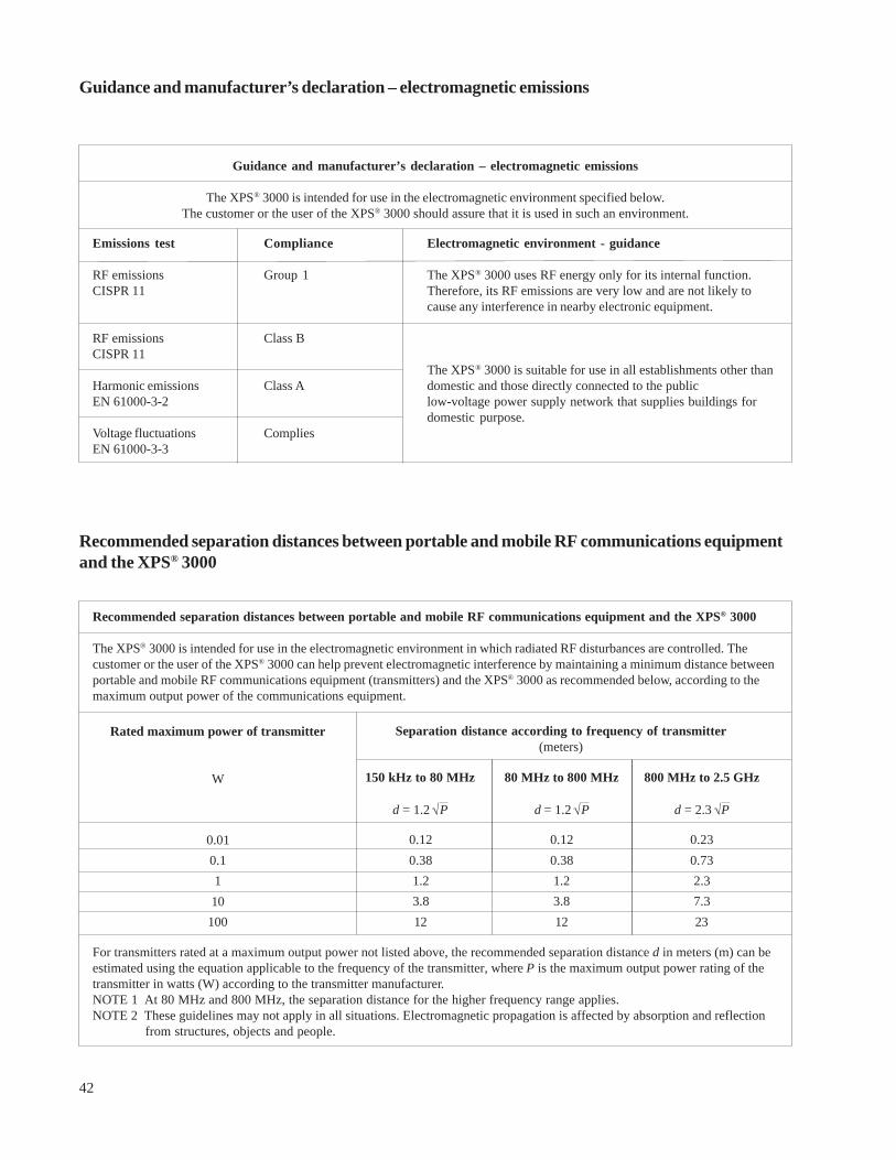
42
Guidance and manufacturer’s declaration – electromagnetic emissions
Recommended separation distances between portable and mobile RF communications equipmentand the XPS® 3000
Recommended separation distances between portable and mobile RF communications equipment and the XPS® 3000
The XPS® 3000 is intended for use in the electromagnetic environment in which radiated RF disturbances are controlled. Thecustomer or the user of the XPS® 3000 can help prevent electromagnetic interference by maintaining a minimum distance betweenportable and mobile RF communications equipment (transmitters) and the XPS® 3000 as recommended below, according to themaximum output power of the communications equipment.
Separation distance according to frequency of transmitter(meters)
Rated maximum power of transmitter
W
For transmitters rated at a maximum output power not listed above, the recommended separation distance d in meters (m) can beestimated using the equation applicable to the frequency of the transmitter, where P is the maximum output power rating of thetransmitter in watts (W) according to the transmitter manufacturer.NOTE 1 At 80 MHz and 800 MHz, the separation distance for the higher frequency range applies.NOTE 2 These guidelines may not apply in all situations. Electromagnetic propagation is affected by absorption and reflection
from structures, objects and people.
0.120.381.23.812
0.120.381.23.812
0.230.732.37.323
Guidance and manufacturer’s declaration – electromagnetic emissions
The XPS® 3000 is intended for use in the electromagnetic environment specified below.The customer or the user of the XPS® 3000 should assure that it is used in such an environment.
Emissions test
RF emissionsCISPR 11
RF emissionsCISPR 11
Harmonic emissionsEN 61000-3-2
Voltage fluctuationsEN 61000-3-3
Electromagnetic environment - guidance
The XPS® 3000 uses RF energy only for its internal function.Therefore, its RF emissions are very low and are not likely tocause any interference in nearby electronic equipment.
The XPS® 3000 is suitable for use in all establishments other thandomestic and those directly connected to the publiclow-voltage power supply network that supplies buildings fordomestic purpose.
Compliance
Group 1
Class B
Class A
Complies
√√
800 MHz to 2.5 GHz
d = 2.3 P
80 MHz to 800 MHz
d = 1.2 P
150 kHz to 80 MHz
d = 1.2 P
0.010.1110
100
√

43
RECOMMENDED ENVIRONMENTAL CONDITIONS
OperatingTemperature: ................................... +10°C to +40°C (+50°F to +104°F)Humidity: ........................................ 30% to 75% RHBarometric Pressure: ....................... 700 to 1060 hPa
StorageTemperature: ................................... -40°C to +70°C (-40°F to +158°F)Humidity: ........................................ 10% to 100% RHBarometric Pressure: ....................... 500 to 1060 hPa
Guidance and manufacturer's declaration - electromagnetic immunity - Part II
Guidance and manufacturer’s declaration – electromagnetic immunity - Part II
The XPS® 3000 is intended for use in the electromagnetic environment specified below.The customer or the user of the XPS® 3000 should assure that it is used in such an environment.
Immunity test
Conducted RF
EN 61000-4-6
Radiated RF
EN 61000-4-3
EN 60601 test level
3 Vrms
150 kHz to 80 MHz
3 V / m
80 MHz to 2.5 GHz
Electromagnetic environment - guidance
Portable and mobile RF communications equip-ment should be used no closer to any part of theXPS® 3000, including cables, than the recom-mended separation distance calculated from theequation applicable to the frequency of thetransmitter.
Recommended separation distance
d = 1.2 P
d = 1.2 P 80 MHz to 800 MHz
d = 2.3 P 800 MHz to 2.5 GHz
where P is the maximum output power rating ofthe transmitter in watts (W) according to thetransmitter manufacturer and d is the recom-mended separation distance in meters (m).Field strengths from fixed RF transmitters, asdetermined by an electromagnetic site survey,ashould be less than the compliance level in eachfrequency range.b
Interference may occur in the vicinity of equip-ment marked with the following symbol:
Compliance level
3 Vrms
3 V / m
NOTE 1 At 80 MHz and 800 MHz, the higher frequency range applies.NOTE 2 These guidelines may not apply in all situations. Electromagnetic propagation is affected by absorption and reflection from
structures, objects and people.
a Field strengths from fixed transmitters, such as base stations for radio (cellular/cordless) telephones and land mobile radios,amateur radio, AM and FM radio broadcast and TV broadcast cannot be predicted theoretically with accuracy. To assess theelectromagnetic environment due to fixed RF transmitters, an electromagnetic site survey should be considered. If the measuredfield strength in the location in which the XPS® 3000 is used exceeds the applicable RF compliance level above, the XPS® 3000should be observed to verify normal operation. If abnormal performance is observed, additional measures may be necessary, suchas re-orienting or relocating the XPS® 3000.
b Over the frequency range 150 kHz to 80 MHz, field strengths should be less than 3 V/m.
√
√
√

Medtronic Xomed, Inc.Jacksonville, FL 32216-0980 U.S.A.
68E3853 B 02/2013
REF 1897851D