CATALOGO CBN 3000 2013. - Suerte
228
-
Upload
khangminh22 -
Category
Documents
-
view
1 -
download
0
Transcript of CATALOGO CBN 3000 2013. - Suerte
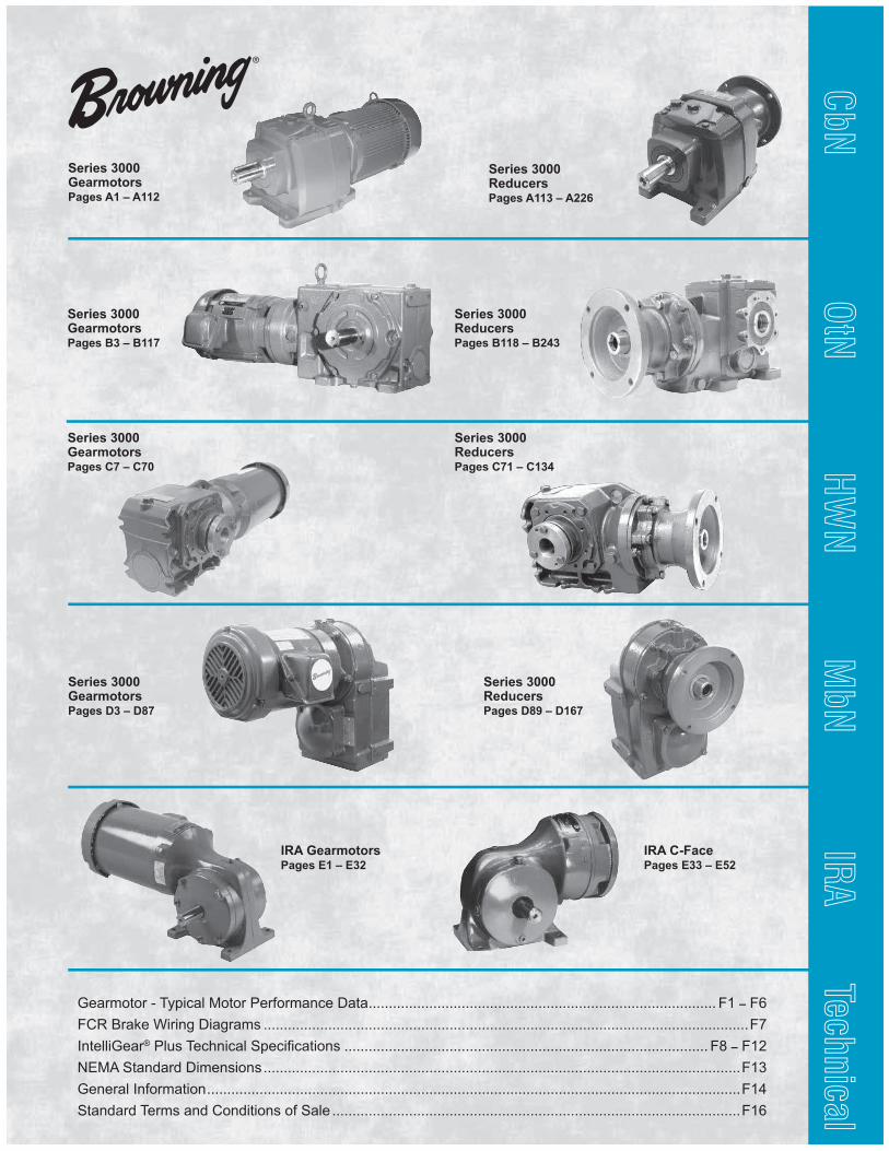
Series 3000ReducersPages A113 – A226
Series 3000ReducersPages B118 – B243
Series 3000ReducersPages C71 – C134
Series 3000GearmotorsPages C7 – C70
Series 3000Gearmotors Pages A1 – A112
Series 3000GearmotorsPages B3 – B117
Series 3000GearmotorsPages D3 – D87
IRA GearmotorsPages E1 – E32
IRA C-FacePages E33 – E52
Series 3000ReducersPages D89 – D167
Gearmotor - Typical Motor Performance Data ...................................................................................... F1 – F6
FCR Brake Wiring Diagrams ........................................................................................................................F7
IntelliGear® !"#$ %&'()*'+" ,-&'*. '+/*0)$ .......................................................................................... F8 – F12
NEMA Standard Dimensions ......................................................................................................................F13
General Information ....................................................................................................................................F14
Standard Terms and Conditions of Sale .....................................................................................................F16
CbN
OtN
HWN
MbN
IRA
Technical

316 Stainless Coating - Corro-Duty Gray
White Epoxy Coating - Corro-Duty® White
These corrosion-resistant coating options are available today in all
sizes for the complete line of Browning® and Morse® speed reducers
and gearmotors. They complement our premium corrosionresistant
engineered solutions, including all the stainless steel Morse Raider® Plus
offerings for the ultimate in corrosion resistance.
Coatings USDA and FDA Accepted
CRES
A-1
CbN
Serie
s
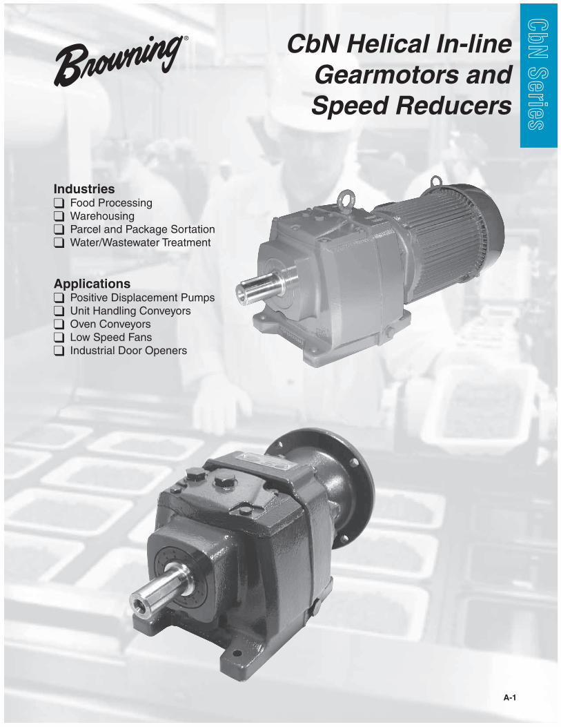
Industries Food Processing Warehousing Parcel and Package Sortation Water/Wastewater Treatment
Applications Positive Displacement Pumps Unit Handling Conveyors Oven Conveyors Low Speed Fans ! Industrial Door Openers
CbN Helical In-line
Gearmotors and
Speed Reducers
A-2
3000SERIESCbN
CbN
Serie
s
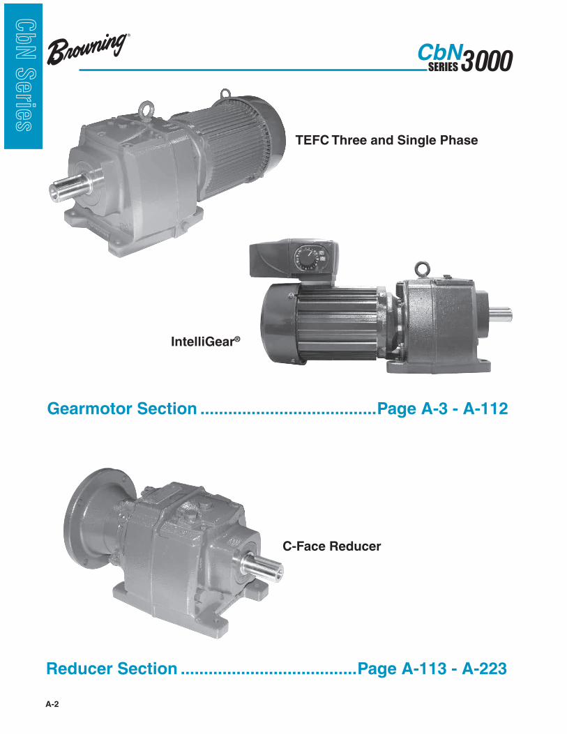
Reducer Section ......................................Page A-113 - A-223
Gearmotor Section ......................................Page A-3 - A-112
IntelliGear®
TEFC Three and Single Phase
C-Face Reducer
A-3
3000SERIESCbN
CbN
Serie
s
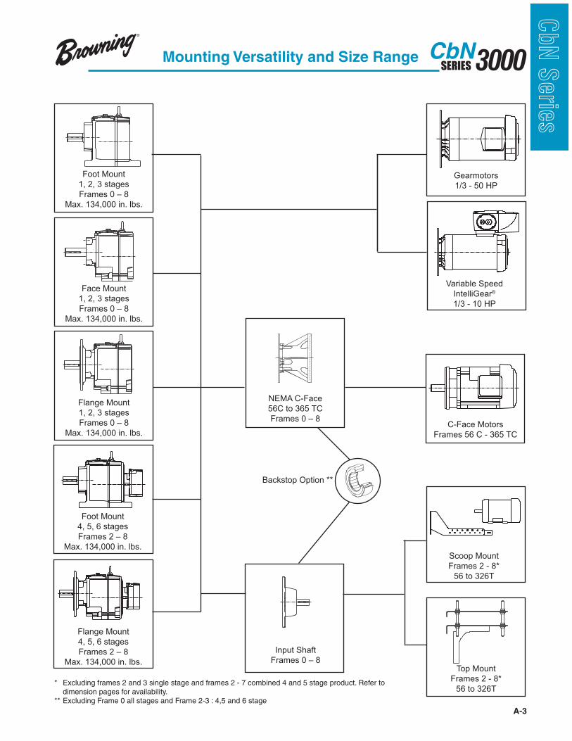
Foot Mount
1, 2, 3 stages
Frames 0 – 8
Max. 134,000 in. lbs.
Face Mount
1, 2, 3 stages
Frames 0 – 8
Max. 134,000 in. lbs.
Mounting Versatility and Size Range
Flange Mount
1, 2, 3 stages
Frames 0 – 8
Max. 134,000 in. lbs.
Foot Mount
4, 5, 6 stages
Frames 2 – 8
Max. 134,000 in. lbs.
Flange Mount
4, 5, 6 stages
Frames 2 – 8
Max. 134,000 in. lbs.
NEMA C-Face
56C to 365 TC
Frames 0 – 8
Input Shaft
Frames 0 – 8Top Mount
Frames 2 - 8*
56 to 326T
Scoop Mount
Frames 2 - 8*
56 to 326T
C-Face Motors
Frames 56 C - 365 TC
Gearmotors
1/3 - 50 HP
Variable Speed
IntelliGear®
1/3 - 10 HP
* Excluding frames 2 and 3 single stage and frames 2 - 7 combined 4 and 5 stage product. Refer to dimension pages for availability.** Excluding Frame 0 all stages and Frame 2-3 : 4,5 and 6 stage
Backstop Option **
A-4
3000SERIESCbN
CbN
Serie
s
General Information
General
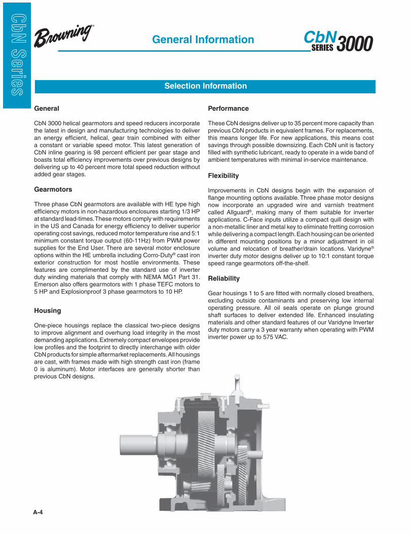
CbN 3000 helical gearmotors and speed reducers incorporate the latest in design and manufacturing technologies to deliver an energy efficient, helical, gear train combined with either a constant or variable speed motor. This latest generation of CbN inline gearing is 98 percent efficient per gear stage and boasts total efficiency improvements over previous designs by delivering up to 40 percent more total speed reduction without added gear stages.
Gearmotors
Three phase CbN gearmotors are available with HE type high efficiency motors in non-hazardous enclosures starting 1/3 HP at standard lead-times. These motors comply with requirements in the US and Canada for energy efficiency to deliver superior operating cost savings, reduced motor temperature rise and 5:1 minimum constant torque output (60-11Hz) from PWM power supplies for the End User. There are several motor enclosure options within the HE umbrella including Corro-Duty® cast iron exterior construction for most hostile environments. These features are complimented by the standard use of inverter duty winding materials that comply with NEMA MG1 Part 31. Emerson also offers gearmotors with 1 phase TEFC motors to 5 HP and Explosionproof 3 phase gearmotors to 10 HP.
Housing
One-piece housings replace the classical two-piece designs to improve alignment and overhung load integrity in the most demanding applications. Extremely compact envelopes provide low profiles and the footprint to directly interchange with older CbN products for simple aftermarket replacements. All housings are cast, with frames made with high strength cast iron (frame 0 is aluminum). Motor interfaces are generally shorter than previous CbN designs.
Selection Information
Performance
These CbN designs deliver up to 35 percent more capacity than previous CbN products in equivalent frames. For replacements, this means longer life. For new applications, this means cost savings through possible downsizing. Each CbN unit is factory filled with synthetic lubricant, ready to operate in a wide band of ambient temperatures with minimal in-service maintenance.
Flexibility
Improvements in CbN designs begin with the expansion of flange mounting options available. Three phase motor designs now incorporate an upgraded wire and varnish treatment called Allguard®, making many of them suitable for inverter applications. C-Face inputs utilize a compact quill design with a non-metallic liner and metal key to eliminate fretting corrosion while delivering a compact length. Each housing can be oriented in different mounting positions by a minor adjustment in oil volume and relocation of breather/drain locations. Varidyne® inverter duty motor designs deliver up to 10:1 constant torque speed range gearmotors off-the-shelf.
Reliability
Gear housings 1 to 5 are fitted with normally closed breathers, excluding outside contaminants and preserving low internal operating pressure. All oil seals operate on plunge ground shaft surfaces to deliver extended life. Enhanced insulating materials and other standard features of our Varidyne Inverter duty motors carry a 3 year warranty when operating with PWM inverter power up to 575 VAC.

A-5
3000SERIESCbN
CbN
Serie
s
Section PageMounting Versatility and Size Range ...............................................................................................................A-6Design Features ..............................................................................................................................................A-7Motor Options ..................................................................................................................................................A-8Gearmotor Selection (constant speed) .................................................................................................A-9 - A-10Gearmotor Selection (variable speed) ................................................................................................A-11 - A-12Catalog Nomenclature ........................................................................................................................A-13 - A-17Mounting Positions ........................................................................................................................................A-15Motor Types and Availability ...............................................................................................................A-16 - A-17Lubrication ......................................................................................................................................A-224 - A-225Modifications, Options and Accessories .............................................................................................A-18 - A-20AGMA Application Classifications ......................................................................................................A-21 - A-23Gearmotor Selection Tables ...............................................................................................................A-24 - A-67Dimension Prints (inch) Three Phase Footed ....................................................................................................................A-68 - A-88 Three Phase Flange Mounted ...................................................................................................A-89 - A-106 Three Phase Footed with Flange .............................................................................................A-107 - A-108 Alternative Motor Types and Dimensions .................................................................................A-109 - A-110 Brake Dimensional Supplement ............................................................................................................A-111Gearmotor Weights......................................................................................................................................A-112Dimension Print Supplements Face Mounted ..........................................................................................................................A-215 - A-216 Metric Output Shafts ................................................................................................................A-217 - A-222Gearmotor – Typical Motor Performance Data ....................................................................................... F-1 - F-7IntelliGear® Technical Specifications ..................................................................................................... F-8 - F-12NEMA Standard Dimensions .............................................................................................................. F-13 - F-14Standard Terms and Conditions of Sale ........................................................................................................F-15
Table of Contents
Gearmotors
A-6
3000SERIESCbN
CbN
Serie
s
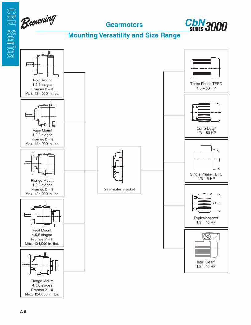
Three Phase TEFC
1/3 – 50 HP
Corro-Duty®
1/3 – 50 HP
IntelliGear®
1/3 – 10 HP
Explosionproof
1/3 – 10 HP
Single Phase TEFC
1/3 – 5 HP
Gearmotors
Mounting Versatility and Size Range
Foot Mount
1,2,3 stages
Frames 0 – 8
Max. 134,000 in. lbs.
Face Mount
1,2,3 stages
Frames 0 – 8
Max. 134,000 in. lbs.
Flange Mount
1,2,3 stages
Frames 0 – 8
Max. 134,000 in. lbs.
Foot Mount
4,5,6 stages
Frames 2 – 8
Max. 134,000 in. lbs.
Flange Mount
4,5,6 stages
Frames 2 – 8
Max. 134,000 in. lbs.
Gearmotor Bracket

A-7
3000SERIESCbN
CbN
Serie
s
5
Type CbN In-line Helical
Series 3000 Gearmotors Features...
Design Features
1. High Efficiency Motor Design Available
2. Innovative, self-locking, taper shaft connection (motor to gear) allows on-site replacement without removing oil, primary pinion, or disconnecting the load.
3. Gearbox is delivered filled with synthetic oil, ready to use.
4. Corrosion resistant, cast iron housings are one piece and ribbed for extra strength. (Size 0 housings are cast aluminum housings.)
5. Gears are made of 8620, heat treated, nickel chromium, molybdenum steel. Helical gearing is skived, superfinished, or ground after case hardening to 58-62 Rc.
6. Multiple breather locations. Breathers are normally closed during construction to exclude contaminants.
7. Double lip seals are installed on plunge ground shafts.
8. Magnetic drain plug is supplied as standard.
21 34
6
7
Gearmotors
Features
A-8
3000SERIESCbN
CbN
Serie
s
Gearmotors
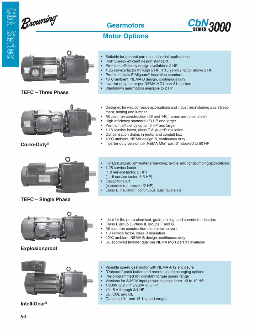
Motor Options
® insulation standard
TEFC – Three Phase
-ment, mining and lumber. ® insulation Corro-Duty®
(1.0 service factor, 2 HP) (1.15 service factor, 3-5 HP)
(capacitor run above 1/2 HP)
TEFC – Single Phase
IntelliGear®
Explosionproof
A-9
3000SERIESCbN
CbN
Serie
s
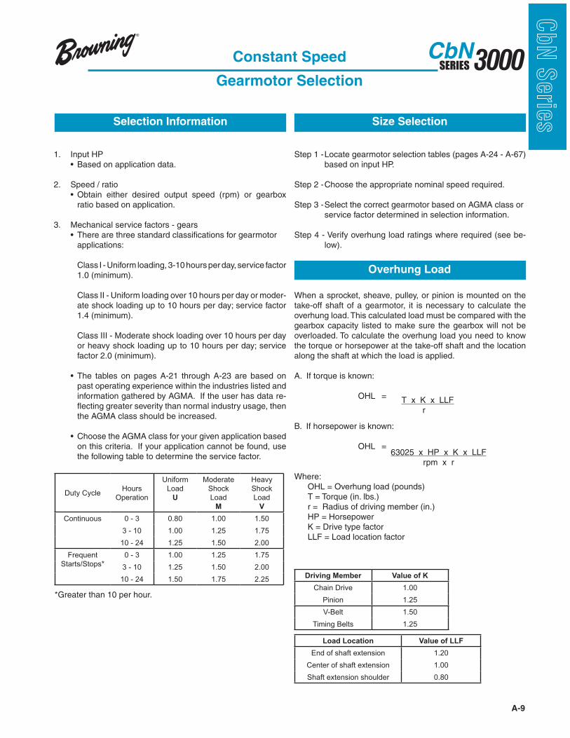
Step 1 - Locate gearmotor selection tables (pages A-24 - A-67) based on input HP.
Step 2 - Choose the appropriate nominal speed required.
Step 3 - Select the correct gearmotor based on AGMA class or service factor determined in selection information.
Step 4 - Verify overhung load ratings where required (see be-low).
When a sprocket, sheave, pulley, or pinion is mounted on the take-off shaft of a gearmotor, it is necessary to calculate the overhung load. This calculated load must be compared with the gearbox capacity listed to make sure the gearbox will not be overloaded. To calculate the overhung load you need to know the torque or horsepower at the take-off shaft and the location along the shaft at which the load is applied.
A. If torque is known: OHL =
B. If horsepower is known: OHL =
Where: OHL = Overhung load (pounds) T = Torque (in. lbs.) r = Radius of driving member (in.) HP = Horsepower K = Drive type factor LLF = Load location factor
1. Input HP
2. Speed / ratio
ratio based on application.
3. Mechanical service factors - gears
applications: Class I - Uniform loading, 3-10 hours per day, service factor
1.0 (minimum).
Class II - Uniform loading over 10 hours per day or moder-
1.4 (minimum).
Class III - Moderate shock loading over 10 hours per day
factor 2.0 (minimum).
past operating experience within the industries listed and information gathered by AGMA. If the user has data re-flecting greater severity than normal industry usage, then the AGMA class should be increased.
on this criteria. If your application cannot be found, use the following table to determine the service factor.
*Greater than 10 per hour.
Size SelectionSelection Information
Overhung Load
T x K x LLFr
63025 x HP x K x LLFrpm x r
Constant Speed
Gearmotor Selection
Duty CycleHours
Operation
Uniform
Load
U
Moderate
Shock
Load
M
Heavy
Shock
Load
V
Continuous 0 - 3 0.80 1.00 1.50
3 - 10 1.00 1.25 1.75
10 - 24 1.25 1.50 2.00
Frequent
Starts/Stops*
0 - 3 1.00 1.25 1.75
3 - 10 1.25 1.50 2.00
10 - 24 1.50 1.75 2.25Driving Member Value of K
Chain Drive 1.00
Pinion 1.25
V-Belt 1.50
Timing Belts 1.25
Load Location Value of LLF
End of shaft extension 1.20
Center of shaft extension 1.00
Shaft extension shoulder 0.80

A-10
3000SERIESCbN
CbN
Serie
s
A horizontal, foot mounted gearmotor is required to operate a uniformly loaded, assembly conveyor at 44 rpm, 24 hours per
the customer requests a 230/460 volt, High Efficiency TEFC motor end.
Step 1... The AGMA service classification table on page A-21 indicates that this is a Class II application.
Step 2... The CbN gearmotor table on page A-44 indicates that a gear frame 3363 will do the job.
Step 3...
To check overhung load for the example:
r = = = 4
K = 1.0 (chain drive)
LLF = 1.2 (sprocket on end of shaft)
HP = 3
Torque formula: OHL =
OHL = = 1289 lbs.
The overhung load capacity of 2305 lbs. listed is greater than the calculated overhung load value of 1289 lbs.
Step 4...
Confirm that no modification is required.
Step 5...
CbN 3363 S B3 40 HT24 182T 3
Example
63025 x HP x K x LLFrpm x r
63025 x 3 x 1.0 x 1.244 x 4
Sprocket Diameter2
82
Output AGMA Service Output Torque OHL Nominal Frame Size Std. Motor
rpm Class Factor in-lb lb Ratio Gear Motor Types !
Constant Speed
Gearmotor Selection
A-11
3000SERIESCbN
CbN
Serie
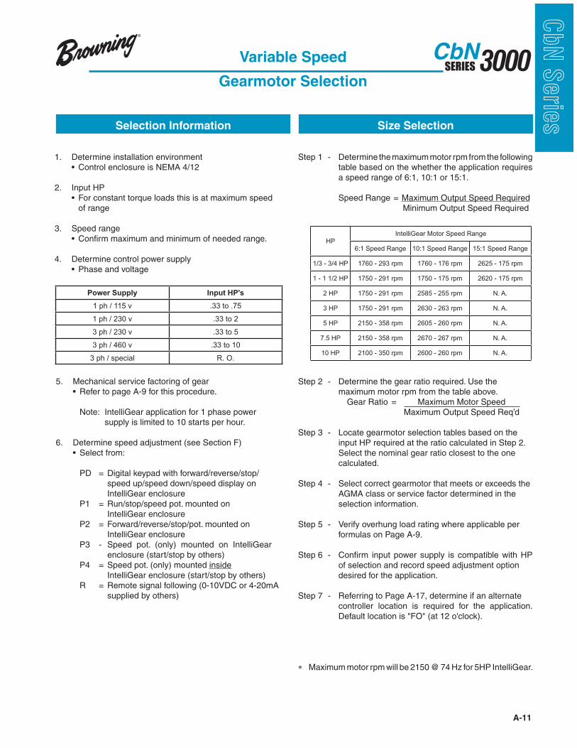
sVariable Speed
Gearmotor Selection
Step 1 - Determine the maximum motor rpm from the following table based on the whether the application requires a speed range of 6:1, 10:1 or 15:1.
Speed Range = Maximum Output Speed Required Minimum Output Speed Required
Step 2 - Determine the gear ratio required. Use the maximum motor rpm from the table above.
Gear Ratio = Maximum Motor Speed Maximum Output Speed Req’d
Step 3 - Locate gearmotor selection tables based on the input HP required at the ratio calculated in Step 2. Select the nominal gear ratio closest to the one calculated.
Step 4 - Select correct gearmotor that meets or exceeds the AGMA class or service factor determined in the selection information.
Step 5 - Verify overhung load rating where applicable per formulas on Page A-9.
Step 6 - Confirm input power supply is compatible with HP of selection and record speed adjustment option desired for the application.
Step 7 - Referring to Page A-17, determine if an alternate controller location is required for the application.
" Maximum motor rpm will be 2150 @ 74 Hz for 5HP IntelliGear.
1. Determine installation environment
2. Input HP of range
3. Speed range 4. Determine control power supply
Size SelectionSelection Information
5. Mechanical service factoring of gear
Note: IntelliGear application for 1 phase power supply is limited to 10 starts per hour.
6. Determine speed adjustment (see Section F)
PD = Digital keypad with forward/reverse/stop/ speed up/speed down/speed display on IntelliGear enclosure P1 = Run/stop/speed pot. mounted on IntelliGear enclosure P2 = Forward/reverse/stop/pot. mounted on IntelliGear enclosure P3 - Speed pot. (only) mounted on IntelliGear
enclosure (start/stop by others) P4 = Speed pot. (only) mounted inside
IntelliGear enclosure (start/stop by others) R = Remote signal following (0-10VDC or 4-20mA supplied by others)
Power Supply Input HP's
1 ph / 115 v .33 to .75
1 ph / 230 v .33 to 2
3 ph / 230 v .33 to 5
3 ph / 460 v .33 to 10
3 ph / special R. O.
HPIntelliGear Motor Speed Range
6:1 Speed Range 10:1 Speed Range 15:1 Speed Range
1/3 - 3/4 HP 1760 - 293 rpm 1760 - 176 rpm 2625 - 175 rpm
1 - 1 1/2 HP 1750 - 291 rpm 1750 - 175 rpm 2620 - 175 rpm
2 HP 1750 - 291 rpm 2585 - 255 rpm N. A.
3 HP 1750 - 291 rpm 2630 - 263 rpm N. A.
5 HP 2150 - 358 rpm 2605 - 260 rpm N. A.
7.5 HP 2150 - 358 rpm 2670 - 267 rpm N. A.
10 HP 2100 - 350 rpm 2600 - 260 rpm N. A.
A-12
3000SERIESCbN
CbN
Serie
s
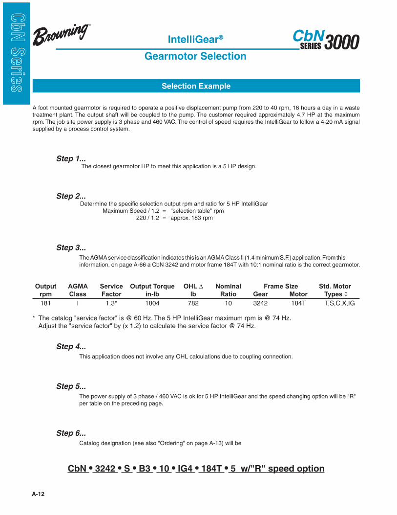
A foot mounted gearmotor is required to operate a positive displacement pump from 220 to 40 rpm, 16 hours a day in a waste treatment plant. The output shaft will be coupled to the pump. The customer required approximately 4.7 HP at the maximum rpm. The job site power supply is 3 phase and 460 VAC. The control of speed requires the IntelliGear to follow a 4-20 mA signal supplied by a process control system.
Step 1... The closest gearmotor HP to meet this application is a 5 HP design.
Step 2... Determine the specific selection output rpm and ratio for 5 HP IntelliGear 220 / 1.2 = approx. 183 rpm
Step 3...
The AGMA service classification indicates this is an AGMA Class II (1.4 minimum S.F.) application. From this information, on page A-66 a CbN 3242 and motor frame 184T with 10:1 nominal ratio is the correct gearmotor.
Output AGMA Service Output Torque OHL Nominal Frame Size Std. Motor
rpm Class Factor in-lb lb Ratio Gear Motor Types !
Step 4...
This application does not involve any OHL calculations due to coupling connection.
Step 5...
per table on the preceding page.
Step 6...
CbN 3242 S B3 10 IG4 184T 5 w/"R" speed option
Selection Example
IntelliGear®
Gearmotor Selection
A-13
3000SERIESCbN
CbN
Serie
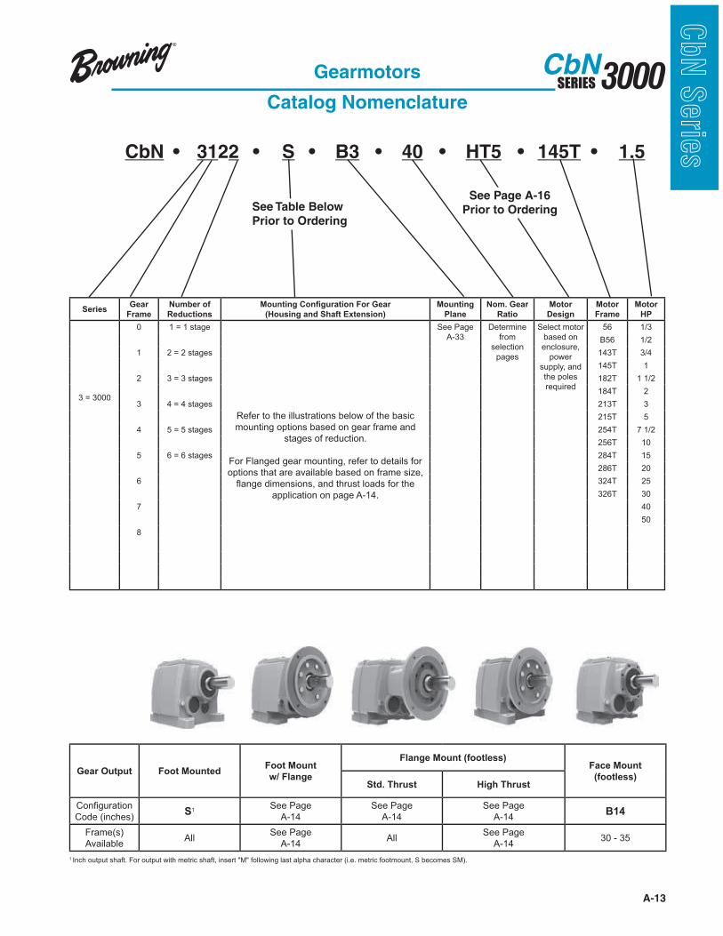
sCbN 3122 S B3 40 HT5 145T 1.5
Gearmotors
Catalog Nomenclature
See Table Below
Prior to Ordering
See Page A-16
Prior to Ordering
SeriesGear
Frame
Number of
Reductions
!"#$%#&'(!#)'&"*+$%!#',!*'-.+*
(Housing and Shaft Extension)
Mounting
Plane
Nom. Gear
Ratio
Motor
Design
Motor
Frame
Motor
HP
3 = 3000
0 1 = 1 stage
Refer to the illustrations below of the basic
mounting options based on gear frame and
stages of reduction.
For Flanged gear mounting, refer to details for
options that are available based on frame size,
!"#$%!&'(%#)'*#)+!"#&!,-./),!0*"&)!1*.!,-%!
application on page A-14.
See Page
A-33
Determine
from
selection
pages
Select motor
based on
enclosure,
power
supply, and
the poles
required
56 1/3
B56 1/2
1 2 = 2 stages 143T 3/4
145T 1
2 3 = 3 stages 182T 1 1/2
184T 2
3 4 = 4 stages 213T 3
215T 5
4 5 = 5 stages 254T 7 1/2
256T 10
5 6 = 6 stages 284T 15
286T 20
6 324T 25
326T 30
7 40
50
8
Gear Output Foot MountedFoot Mount
w/ Flange
Flange Mount (footless)Face Mount
(footless)Std. Thrust High Thrust
2*#3!$/.",'*#!
Code (inches)S1
See Page
A-14
See Page
A-14
See Page
A-14B14
Frame(s)
AvailableAll
See Page
A-14All
See Page
A-1430 - 35
1 Inch output shaft. For output with metric shaft, insert "M" following last alpha character (i.e. metric footmount, S becomes SM).
A-14
3000SERIESCbN
CbN
Serie
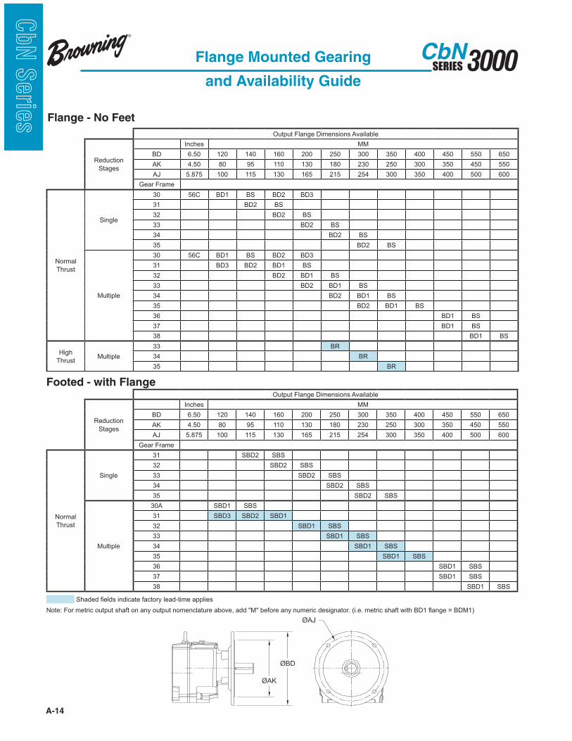
s Flange - No Feet
Flange Mounted Gearing
and Availability Guide
Output Flange Dimensions Available
Reduction
Stages
Inches MM
BD 6.50 120 140 160 200 250 300 350 400 450 550 650
AK 4.50 80 95 110 130 180 230 250 300 350 450 550
AJ 5.875 100 115 130 165 215 254 300 350 400 500 600
Gear Frame
Normal
Thrust
Single
30 56C BD1 BS BD2 BD3
31 BD2 BS
32 BD2 BS
33 BD2 BS
34 BD2 BS
35 BD2 BS
Multiple
30 56C BD1 BS BD2 BD3
31 BD3 BD2 BD1 BS
32 BD2 BD1 BS
33 BD2 BD1 BS
34 BD2 BD1 BS
35 BD2 BD1 BS
36 BD1 BS
37 BD1 BS
38 BD1 BS
High
ThrustMultiple
33 BR
34 BR
35 BR
Footed - with Flange Output Flange Dimensions Available
Reduction
Stages
Inches MM
BD 6.50 120 140 160 200 250 300 350 400 450 550 650
AK 4.50 80 95 110 130 180 230 250 300 350 450 550
AJ 5.875 100 115 130 165 215 254 300 350 400 500 600
Gear Frame
Normal
Thrust
Single
31 SBD2 SBS
32 SBD2 SBS
33 SBD2 SBS
34 SBD2 SBS
35 SBD2 SBS
Multiple
30A SBD1 SBS
31 SBD3 SBD2 SBD1
32 SBD1 SBS
33 SBD1 SBS
34 SBD1 SBS
35 SBD1 SBS
36 SBD1 SBS
37 SBD1 SBS
38 SBD1 SBS
4-"&%&!3%0&)!'#&'5",%!1"5,*.6!0%"&7,'(%!"880'%)
9*,%:!;*.!(%,.'5!*/,8/,!)-"1,!*#!"#6!*/,8/,!#*(%#50",/.%!"<*=%+!"&&!>?>!<%1*.%!"#6!#/(%.'5!&%)'$#",*.@!A'@%@!(%,.'5!)-"1,!B',-!CDE! "#$%!F!CD?EG

A-15
3000SERIESCbN
CbN
Serie
sGearmotors
Mounting Positions
Flange Mounted (footless)
Multiple Reductions
Flange Mounted (footless)
Single Reduction
Foot Mounted
(with/without flange)
Any Reduction
A-16
3000SERIESCbN
CbN
Serie
s
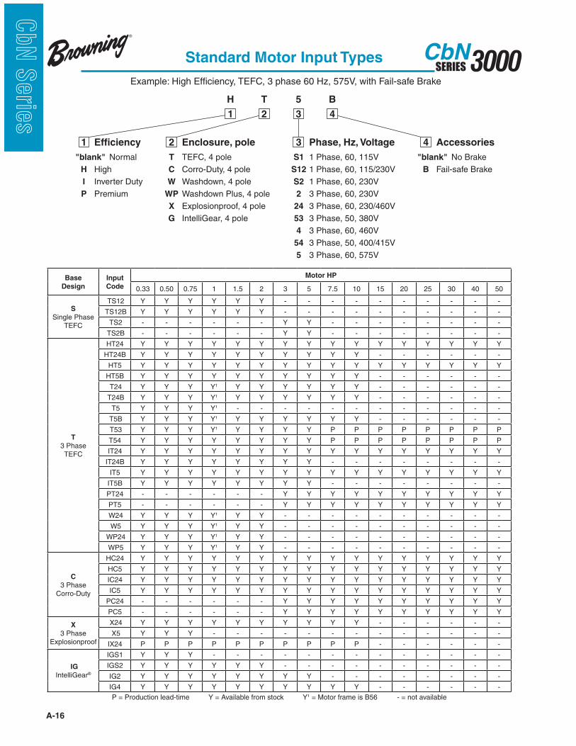
Standard Motor Input Types
Example: High Efficiency, TEFC, 3 phase 60 Hz, 575V, with Fail-safe Brake
"blank" Normal
H High
I Inverter Duty
P Premium
1 Efficiency
T TEFC, 4 pole
C Corro-Duty, 4 pole
W Washdown, 4 pole
WP Washdown Plus, 4 pole
X Explosionproof, 4 pole
G IntelliGear, 4 pole
2 Enclosure, pole
"blank" No Brake
B Fail-safe Brake
4 Accessories
1
H
2
T
3
5
4
B
S1 1 Phase, 60, 115V
S12 1 Phase, 60, 115/230V
S2 1 Phase, 60, 230V
2 3 Phase, 60, 230V
24 3 Phase, 60, 230/460V
53 3 Phase, 50, 380V
4 3 Phase, 60, 460V
54 3 Phase, 50, 400/415V
5 3 Phase, 60, 575V
3 Phase, Hz, Voltage
Base
Design
Input
Code
Motor HP
0.33 0.50 0.75 1 1.5 2 3 5 7.5 10 15 20 25 30 40 50
S Single Phase
TEFC
TS12 Y Y Y Y Y Y - - - - - - - - - -
TS12B Y Y Y Y Y Y - - - - - - - - - -
TS2 - - - - - - Y Y - - - - - - - -
TS2B - - - - - - Y Y - - - - - - - -
T 3 Phase TEFC
HT24 Y Y Y Y Y Y Y Y Y Y Y Y Y Y Y Y
HT24B Y Y Y Y Y Y Y Y Y Y - - - - - -
HT5 Y Y Y Y Y Y Y Y Y Y Y Y Y Y Y Y
HT5B Y Y Y Y Y Y Y Y Y Y - - - - - -
T24 Y Y Y Y1 Y Y Y Y Y Y - - - - - -
T24B Y Y Y Y1 Y Y Y Y Y Y - - - - - -
T5 Y Y Y Y1 - - - - - - - - - - - -
T5B Y Y Y Y1 Y Y Y Y Y Y - - - - - -
T53 Y Y Y Y1 Y Y Y Y P P P P P P P P
T54 Y Y Y Y Y Y Y Y P P P P P P P P
IT24 Y Y Y Y Y Y Y Y Y Y Y Y Y Y Y Y
IT24B Y Y Y Y Y Y Y Y - - - - - - - -
IT5 Y Y Y Y Y Y Y Y Y Y Y Y Y Y Y Y
IT5B Y Y Y Y Y Y Y Y - - - - - - - -
PT24 - - - - - - Y Y Y Y Y Y Y Y Y Y
PT5 - - - - - - Y Y Y Y Y Y Y Y Y Y
W24 Y Y Y Y1 Y Y - - - - - - - - - -
W5 Y Y Y Y1 Y Y - - - - - - - - - -
WP24 Y Y Y Y1 Y Y - - - - - - - - - -
WP5 Y Y Y Y1 Y Y - - - - - - - - - -
C 3 Phase
Corro-Duty
HC24 Y Y Y Y Y Y Y Y Y Y Y Y Y Y Y Y
HC5 Y Y Y Y Y Y Y Y Y Y Y Y Y Y Y Y
IC24 Y Y Y Y Y Y Y Y Y Y Y Y Y Y Y Y
IC5 Y Y Y Y Y Y Y Y Y Y Y Y Y Y Y Y
PC24 - - - - - - Y Y Y Y Y Y Y Y Y Y
PC5 - - - - - - Y Y Y Y Y Y Y Y Y Y
X 3 Phase
Explosionproof
Y Y Y Y Y Y Y Y Y Y - - - - - -
Y Y Y - - - - - - - - - - - - -
P P P P P P P P P P - - - - - -
IG IntelliGear®
IGS1 Y Y Y - - - - - - - - - - - - -
IGS2 Y Y Y Y Y Y - - - - - - - - - -
IG2 Y Y Y Y Y Y Y Y - - - - - - - -
IG4 Y Y Y Y Y Y Y Y Y Y - - - - - -
P = Production lead-time Y = Available from stock Y1 = Motor frame is B56 - = not available
A-17
3000SERIESCbN
CbN
Serie
s
3 o'clock
6 o'clock
9 o'clock
12 o'clock
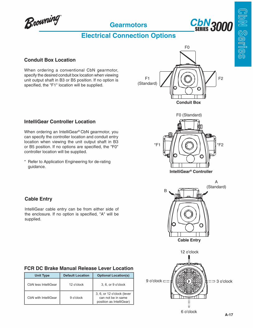
Gearmotors
Electrical Connection Options
F1(Standard)
F0
F2
Conduit Box
*F1 *F2
F0 (Standard)
IntelliGear® Controller
B
A (Standard)
Cable Entry
Conduit Box Location
When ordering a conventional CbN gearmotor, specify the desired conduit box location when viewing unit output shaft in B3 or B5 position. If no option is
IntelliGear Controller Location
When ordering an IntelliGear® CbN gearmotor, you can specify the controller location and conduit entry location when viewing the unit output shaft in B3
controller location will be supplied.
* Refer to Application Engineering for de-rating guidance.
Cable Entry
IntelliGear cable entry can be from either side of
supplied.
FCR DC Brake Manual Release Lever Location
Unit Type Default Location Optional Location(s)
CbN less IntelliGear 12 o'clock 3, 6, or 9 o'clock
CbN with IntelliGear 9 o'clock
3, 6, or 12 o'clock (lever
can not be in same
position as IntelliGear)
A-18
3000SERIESCbN
CbN
Serie
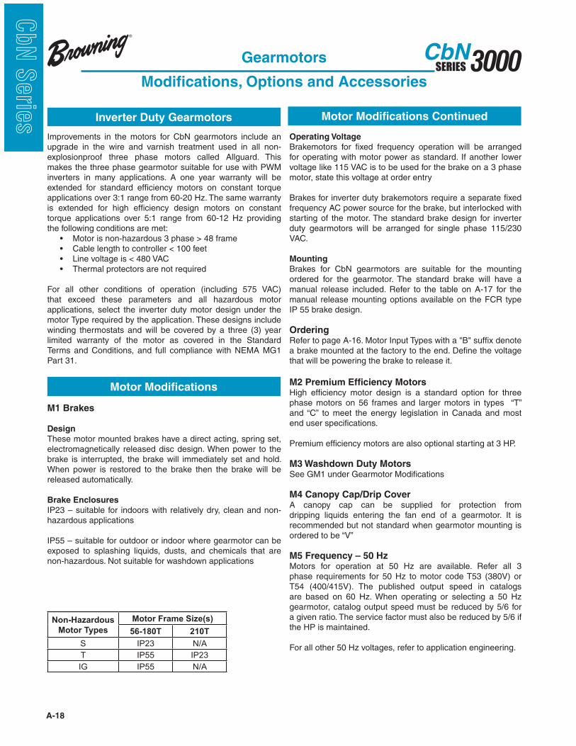
s Inverter Duty Gearmotors
Motor Modifications
Improvements in the motors for CbN gearmotors include an upgrade in the wire and varnish treatment used in all non-explosionproof three phase motors called Allguard. This makes the three phase gearmotor suitable for use with PWM inverters in many applications. A one year warranty will be extended for standard efficiency motors on constant torque applications over 3:1 range from 60-20 Hz. The same warranty is extended for high efficiency design motors on constant torque applications over 5:1 range from 60-12 Hz providing the following conditions are met:
For all other conditions of operation (including 575 VAC) that exceed these parameters and all hazardous motor applications, select the inverter duty motor design under the motor Type required by the application. These designs include winding thermostats and will be covered by a three (3) year limited warranty of the motor as covered in the Standard Terms and Conditions, and full compliance with NEMA MG1 Part 31.
Gearmotors
Modifications, Options and Accessories
M1 Brakes
Design
These motor mounted brakes have a direct acting, spring set, electromagnetically released disc design. When power to the brake is interrupted, the brake will immediately set and hold. When power is restored to the brake then the brake will be released automatically.
Brake Enclosures
IP23 – suitable for indoors with relatively dry, clean and non-hazardous applications
IP55 – suitable for outdoor or indoor where gearmotor can be exposed to splashing liquids, dusts, and chemicals that are non-hazardous. Not suitable for washdown applications
Motor Modifications Continued
Operating Voltage
Brakemotors for fixed frequency operation will be arranged for operating with motor power as standard. If another lower voltage like 115 VAC is to be used for the brake on a 3 phase motor, state this voltage at order entry
Brakes for inverter duty brakemotors require a separate fixed frequency AC power source for the brake, but interlocked with starting of the motor. The standard brake design for inverter duty gearmotors will be arranged for single phase 115/230 VAC.
Mounting
Brakes for CbN gearmotors are suitable for the mounting ordered for the gearmotor. The standard brake will have a manual release included. Refer to the table on A-17 for the manual release mounting options available on the FCR type IP 55 brake design.
Ordering
a brake mounted at the factory to the end. Define the voltage that will be powering the brake to release it.
M2 Premium Efficiency MotorsHigh efficiency motor design is a standard option for three phase motors on 56 frames and larger motors in types “T” and “C” to meet the energy legislation in Canada and most end user specifications.
Premium efficiency motors are also optional starting at 3 HP.
M3 Washdown Duty MotorsSee GM1 under Gearmotor Modifications
M4 Canopy Cap/Drip CoverA canopy cap can be supplied for protection from dripping liquids entering the fan end of a gearmotor. It is recommended but not standard when gearmotor mounting is ordered to be “V”
M5 Frequency – 50 HzMotors for operation at 50 Hz are available. Refer all 3 phase requirements for 50 Hz to motor code T53 (380V) or T54 (400/415V). The published output speed in catalogs are based on 60 Hz. When operating or selecting a 50 Hz gearmotor, catalog output speed must be reduced by 5/6 for a given ratio. The service factor must also be reduced by 5/6 if the HP is maintained.
For all other 50 Hz voltages, refer to application engineering.
Non-Hazardous
Motor Types
Motor Frame Size(s)
56-180T 210T
S IP23 N/A
T IP55 IP23
IG IP55 N/A

A-19
3000SERIESCbN
CbN
Serie
s
M6 Voltage (3 phase only)Standard voltages are listed in the table below. 200 VAC will be handled by 208-230/460V motors up to 10 HP. Refer all other voltages to the Pricing Group to confirm availability.
M7 Motor InsulationEmerson’s 3 phase motors are built with a premium Class F
type motors use a Class B insulation.
Tropical insulation treatment is available as a modification on any motor designs noted above
Class H insulation systems require production lead-times and
M8 Space Heaters Space heaters are recommended for gearmotors installed in very damp locations to prevent condensation from forming on the motor windings when the motor is not operating. Leads will be brought out to the standard motor conduit box. Space heater voltages (115, 230, and 460V) must be specified when
M9 Thermal Protection – ThermostatsThis protection uses a bi-metallic disc thermostat embedded each phase of the motor winding and then connected by others into the holding circuit of the motor starter or VFD drive. The sensor is normally closed, and opens the control circuit to shut the motor down if the motor achieves over-temperature conditions based on the motor insulation class or design code. Thermostats give protection for running overloads, abnormally high ambient, voltage imbalance, high or low voltage, and ventilation failure. Thermostats do not give protection for locked rotor, starting overloads or single phasing.
Thermostats are standard in inverter duty motor designs (including IG) as well as explosionproof dual label motors type
Frequency 3 Phase Voltages Thru 30 HP
60 Hz 200, 230, 460, 575
50 Hz 380, 400/415
Gear Modifications
Gearmotors
Modifications, Options and Accessories
Motor Modifications Continued
G11 Corro-Duty® Corro-Duty treatment can be applied to a gearmotor or reducer when corrosive chemicals or unit will be operated outside in adverse environmental conditions. For gearmotors, the unit should start with specification of the Corro-Duty® type “C” motor design. Other special features of this treatment include: o Grey Option ! 316 stainless steel paint (3 step) ! Light grey semigloss finish ! USDA and FDA approved o White Option ! Two step epoxy paint system ! White gloss finish ! USDA and FDA approved
For washdown application for gearmotors, refer to GM1 Washdown Duty Gearmotors and/or Washdown Duty Gearmotor PLUS.
G12a Foodgrade Synthetic LubricantWhen this modification is specified, the CbN oil sump is filled with the required volume of an FDA approved H1 rated synthetic lubricant for helical gearing (refer to page A-224).
G15 Export BoxingExport boxing can be provided for “under-deck” transport. When the quantity of CbN gearmotors or reducers exceeds five (5) units, refer to international sales for most economical accommodations.
G16 Extra or Special NameplateUnits can be provided with limited additional special information on the standard product nameplate. When required, an extra nameplate may be provided, stamped with custom markings.
A-20
3000SERIESCbN
CbN
Serie
s
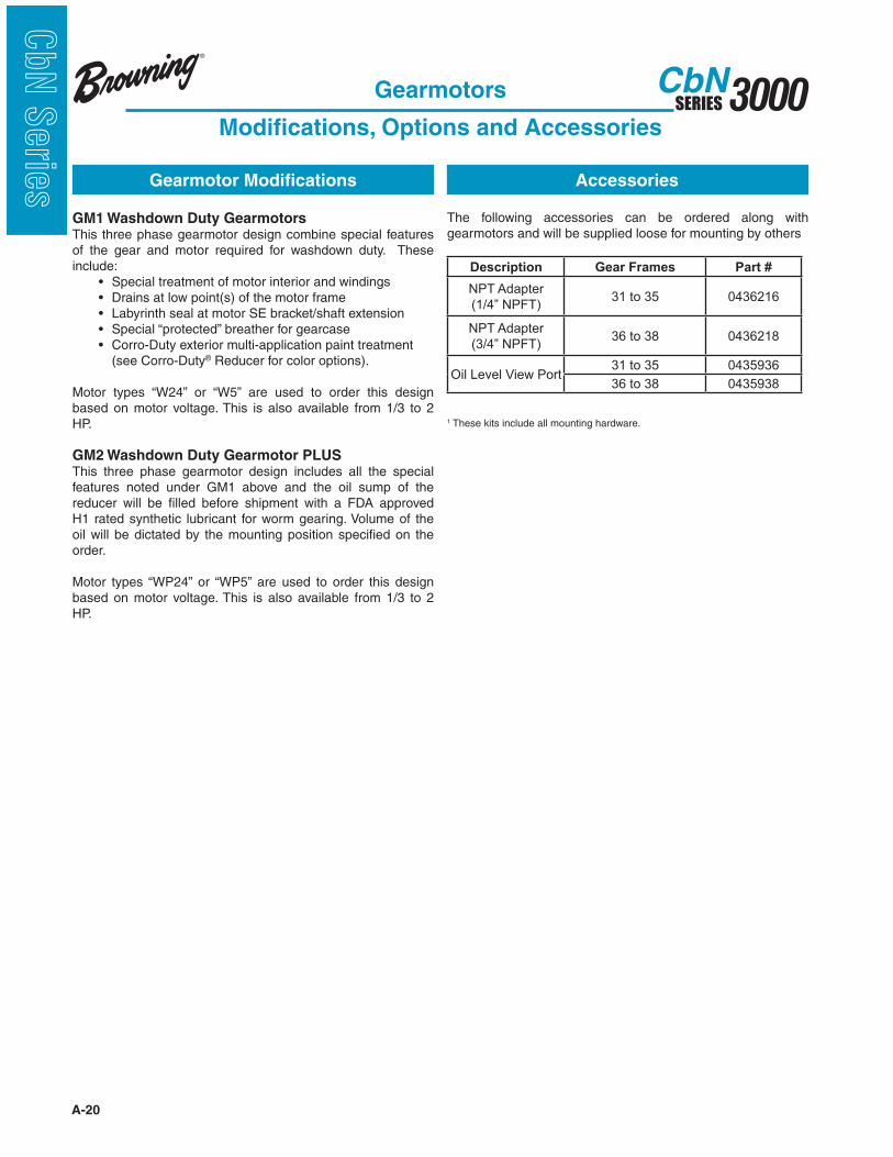
Description Gear Frames Part #
NPT Adapter
(1/4” NPFT)31 to 35 0436216
NPT Adapter
(3/4” NPFT)36 to 38 0436218
Oil Level View Port31 to 35 0435936
36 to 38 0435938
Gearmotor Modifications Accessories
Gearmotors
Modifications, Options and Accessories
The following accessories can be ordered along with gearmotors and will be supplied loose for mounting by others
GM1 Washdown Duty GearmotorsThis three phase gearmotor design combine special features of the gear and motor required for washdown duty. These include: (see Corro-Duty® Reducer for color options).
Motor types “W24” or “W5” are used to order this design based on motor voltage. This is also available from 1/3 to 2 HP.
GM2 Washdown Duty Gearmotor PLUSThis three phase gearmotor design includes all the special features noted under GM1 above and the oil sump of the reducer will be filled before shipment with a FDA approved H1 rated synthetic lubricant for worm gearing. Volume of the oil will be dictated by the mounting position specified on the order.
Motor types “WP24” or “WP5” are used to order this design based on motor voltage. This is also available from 1/3 to 2 HP.
1 These kits include all mounting hardware.

A-21
3000SERIESCbN
CbN
Serie
s
Conveyors - Uniformly Loaded or Fed: Apron, Ass- embly, Belt, Bucket, Chain, Flight, Oven, Screw U I II
Conveyors - Heavy Duty Not Uniformly Fed: Apron, Assembly, Belt, Bucket, Chain, Flight, Oven, Screw M II II Live Roll (Package) U I II Reciprocating, shaker V III III Cookers (Brewing &
Distilling) (Food) U I II
Cooling Tower Fans
Induced Draft M II II Forced Draft Refer to Application Engr. Couch (Paper) M - II
Cranes and Hoists
Main Hoists Heavy Duty V III III Medium Duty M II II Reversing V II II Skip Hoists M II II Trolley Drive M II II Bridge Drive M II II
Crushers
Ore or Stone V III III Cutters (Paper) V - III Cylinders (Paper) M - II
Dewatering Screens
(Sewage) M II II Disc Feeders U I II Distilling (See Brewing)
Double Acting Pumps
2 or more Cylinders M II II Single Cylinder Refer to Application Engr.
Dough Mixer (Food) M II II
Draw Bench
(Metal Mills)
Carriage & Main Drive V III III
Dredges
Cable Reels M II - Conveyors M II II Cutter Head Drives V III III Jig Drives V III III Maneuvering Winches M II - Pumps M II II Screen Drives V III III Stackers M II II Utility Winches M II -
Bucket
Conveyors, Uniform U I II Conveyors, Heavy Duty M II II Elevators Cont. U I II Elevators Uniform U I II Elevators, Heavy Duty M II II
Calenders
Paper U - II Super (Paper) U - II Rubber M II II Textile M II II
Cane Knives M II II Can Filling Machines U I II Card Machines (Textile) M II II Car Dumpers V III -
Car Pullers M II -
Cement Kilns Refer to Application Engr.
Centrifugal
Blowers, Compressors, Dis- charge Elevators or Pumps U I II
Chain Conveyors
Uniformly Loaded or Fed U I II Heavy Duty M II II
Chemical Feeders
(Sewage) U I II Clarifiers U I II Classifiers M II II Clay Working Industry Brick Press V III III Briquette Machine V III III Clay Working Machinery M II II Pug Mill M II II
Collectors (Sewage) U I II
Compressors Centrifugal U I II Lobe M II II Reciprocating, Multi - Cylinder M II II Single - Cylinder V III III
Concrete Mixers
Continuous M II II Intermittent U I -
Converting Machines
(Paper) M - II
Agitators Paper Mills M II II Pure Liquids U I II Liquids & Solids M II II Liquids - Variable Density M II II Apron Conveyors
Uniformly Loaded or Fed U I II Heavy Duty M II II Apron Feeders M II II
Assembly Conveyors
Uniformly Loaded or Fed U I II Heavy Duty M II II Ball Mills V III III
Barking
Drums V - III Hydraulic Auxiliaries V - III Mechanical V - III
Barscreens (Sewage) U I II Batchers (Textile) M II II Beaters and Pulpers
(Paper) U - II
Belt Conveyors
Uniformly Loaded or Fed U I II Heavy Duty M II II Belt Feeders M II II Bending Rolls
(Machine) M II II
Bleachers (Paper) M - II Blowers
Centrifugal U I II Lobe M II II Vane U I II
Bottling Machinery U I II
Brewing and Distilling
Bottling Machinery U I II Brew Kettles, Cont. Duty U - II Can Filling Machines U I II Cookers - Cont. Duty U - II Mash Tubs - Cont. Duty U - II Scale Hoppers - Frequent Starts M II II
Brick Press
(Clay Working) V III III Briquette Machines
(Clay Working) V III III
Up to Over
10 10
hrs/day hrs/day
Up to Over
10 10
hrs/day hrs/day
Up to Over
10 10
hrs/day hrs/day
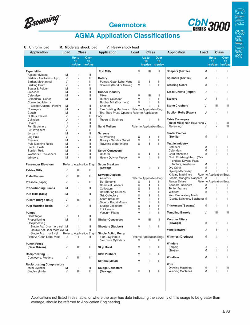
U: Uniform load M: Moderate shock load V: Heavy shock load
Application Load Class Application Load Class Application Load Class
Gearmotors
AGMA Application Classifications

A-22
3000SERIESCbN
CbN
Serie
s U: Uniform load M: Moderate shock load V: Heavy shock load
Up to Over
10 10
hrs/day hrs/day
Application Load Class
Up to Over
10 10
hrs/day hrs/day
Up to Over
10 10
hrs/day hrs/day
Application Load Class Application Load Class
Dryers (Paper) U - II
Dryers and Coolers
(Mills, Rotary) M II II
Dyeing Machinery
(Textile) M II II
Elevators
Bucket - Uniform Load U I II
Bucket - Heavy Duty M II II
Bucket - Continuous U I II
Centrifugal Discharge U I II
Escalators U I II
Freight M II II
Gravity Discharge U I II
Man Lifts, Passenger Refer to Application Engr.
Escalators U I II
Fans
Centrifugal M II II
Cooling Towers
Induced Draft M II II
Forced Draft Refer to Application Engineering Induced Draft M II II
Large (Mine, etc.) M II II
Large Industrial M II II
Light (Small Diameter) U I II
Feeders
Apron, belt M II II
Disc U I II
Reciprocating V III III
Screw M II II
Felt
Stretchers (Paper) U - II
Whippers (Paper) U - II
Flight
Conveyors, Uniform U I II
Conveyors, Heavy M II II
Food Industry
Beet Slicers M II II
Bottling, Can Filling Mach. U I II
Cereal Cookers U I II
Dough Mixers M II II
Meat Grinders M II II
Forming Machines
(Metal Mills) V III III
Generators (Not welding) U I II
Gravity Discharge
Elevators U I II
Grit Collectors
(Sewage) U I II
Machine Tools
Auxiliary Drives U I II
Bending Rolls M II II
Main Drives M II II
Notching Press (Belted) Refer to Application Engr. Plate Planers V III III
Punch Press (Geared) V III III
Tapping Machines V III III
Mangle (Textile) M II II
Mash Tubs (Brewing and
Distilling) U - II
Meat Grinder (Food) M II II
Metal Mills
Draw Bench Carriages
& Main Drives V III III
Forming Machines V III III
Pinch, Dryer & Scrubber
Rolls Reversing Refer to Application Engr. Slitters M II II
Table Conveyors,
Non-Reversing M II III
Reversing V - III
Wire Drawing &
Flattening Machines M II III
Wire Winding Machines M II II
Mills, Rotary Type
Ball, Pebble, Rod V III III
Cement Kilns Refer to Application Engr. Coolers, Dryers, Kilns V II II
Tumbling Barrels V III III
Mixers (Also see Agitators)
Concrete - Continuous M II II
Concrete - Intermittent M I -
Constant Density U I II
Variable Density M II II
Nappers (Textile) M II II
Oil Industry
Chillers M II II
Oil Well Pumping Refer to Application Engr. !"#"$%& '()*+# !#+,, - .. ..
Rotary Kilns M II II
Ore Crushers V III III
Oven Conveyors
Uniform U I II
Heavy Duty M II II
Hammer Mills V III III
Induced Draft Fans M II II
Jordans (Paper) U - II
Kilns (Mills, Rotary) M II II
Cement Refer to Application Engr.
Laundry Washers and
Tumblers M II II
Line Shafts
Heavy Shock Load V III III
Moderate Shock Load M II II
Uniform Load U I II
Live Roll Conveyors
Package U I II
Lobe Blower or
Compressors M II II
Log Hauls (Paper and
Lumber) V III III
Looms (Textile) M II II
Lumber Industry
Barkers - Spindle Feed V II III
Barkers - Main Drive V III III
Carriage Drive Refer to Application Engr. Conveyors
Burner V II III
Main or Heavy Duty V II III
Main Log V III III
Re-Saw Merry-Go-Round V II III
Slab V III III
Transfer V II III
Chains - Floor V II III
Chains - Green V II III
Cut-Off Saws-Chain V II III
Cut-Off Saws-Drag V II III
Debarking Drums V III III
Feeds - Edger V II III
Feeds - Gang V III III
Feeds - Trimmer V II III
Log Deck V III III
Log Hauls - Incline,
Well Type V III III
Log Turning Devices V III III
Planer Feed V II III
Planer Tilting Hoists V II III
Rolls - Live-Off Bearing
Roll Cases V III III
Sorting Table V II III
Tipple Hoist V II III
Transfers - Chain V II III
Transfers - Craneway V II III
Tray Drives V II III
Gearmotors
AGMA Application Classifications
A-23
3000SERIESCbN
CbN
Serie
sU: Uniform load M: Moderate shock load V: Heavy shock load
Up to Over
10 10
hrs/day hrs/day
Application Load Class
Up to Over
10 10
hrs/day hrs/day
Up to Over
10 10
hrs/day hrs/day
Application Load Class Application Load Class
Paper Mills
Agitator (Mixers) M II II Barker - Auxiliaries - Hyd. V - III Barker, Mechanical V - III Barking Drum V - III Beater & Pulper M - II Bleacher M - II Calenders M - II Calenders - Super M - II Converting Mach.- Except Cutters - Platers M - II Conveyors M - II Couch M - II Cutters, Platers V - III Cylinders U - II Dryers U - II Felt Stretchers U - II Felt Whippers V - III Jordans M - II Log Haul V - III Presses M - II Pulp Machine Reels M - II Stock Chests M - II Suction Rolls M - II Washers & Thickeners M - II Winders M - II Passenger Elevators Refer to Application Engr.
Pebble Mills V III III
Plate Planers V III III
Presses (Paper) V - III
Proportioning Pumps M II II
Pub Mills (Clay) M II II
Pullers (Barge Haul) V III III
Pulp Machine Reels U - II
Pumps
Centrifugal U I II Proportioning M II II Reciprocating Single Act., 3 or more cyl. M II II Double Act., 2 or more cyl. M II II Single Act., 1 or 2 cyl. Refer to Application Engr. Rotary: Gear, Lobe, Vane U I II
Punch Press
(Gear Driven) V III III Reciprocating
Conveyors, Feeders V III III Reciprocating Compressors
Multi-Cylinder M II II Single cylinder V III III
Rod Mills V III III
Rotary
Pumps, Gear, Lobe, Vane U I II Screens (Sand or Gravel) V II II
Rubber Industry
Mixer V III III Rubber Calender M II II Rubber Mill (2 or more) M II II Sheeter M II II Tire Building Machines Refer to Application Engr. Tire, Tube Press Openers Refer to Application Engr. Tubers & Strainers M II II Sand Mullers Refer to Application Engr.
Screens
Air Washing U I II Rotary - Sand or Gravel M II II Traveling Water Intake U I II
Screw Conveyors
Uniform U I II Heavy Duty or Feeder M II II
Scum Breakers
(Sewage) M II II
Sewage Disposal
Aerators Refer to Application Engr. Bar Screens U I II Chemical Feeders U I II Collectors U I II Dewatering Screens M II II Grit Collectors U I II Scum Breakers M II II Slow or Rapid Mixers M II II Sludge Collectors U I II Thickeners M II II Vacuum Filters M II II
Shaker Conveyors V III III
Sheeters (Rubber) M II II
Single Acting Pump
1 or 2 Cylinders Refer to Application Engr. 3 or more Cylinders M II II Skip Hoist M II II
Slab Pushers M II II
Slitters (Metal) M II II
Sludge Collectors
(Sewage) U I II
Soapers (Textile) M II II
Spinners (Textile) M II II
Steering Gears M II II
Stock Chests (Paper) U - II
Stokers U I II Stone Crushers V III III
Suction Rolls (Paper) U - II
Table Conveyors
(Metal Mills) Non-Reversing V II III Reversing V - III
Tenter Frames
(Textile) M II II
Textile Industry
Batchers M II II Calenders M II II Card Machines M II II Cloth Finishing Mach. (Cal- enders, Dryers, Pads, Tenters, Washers) M II II Dry Cans M II II Dyeing Machinery M II II Knitting Machinery Refer to Application Engr. Looms, Mangles, Nappers M II II Range Drives Refer to Application Engr. Soapers, Spinners M II II Tenter Frames M II II Winders M II II Yarn Preparatory Mach. (Cards, Spinners, Slashers) M II II
Thickeners (Sewage) M II II
Tumbling Barrels V III III
Vacuum Filters
(sewage) M II II
Vane Blowers U I II
Winches (Dredges) M II -
Winders
(Paper) U - II (Textile) M II II
Windlass M II II
Wire
Drawing Machines M II III Winding Machines M II II
Applications not listed in this table, or where the user has data indicating the severity of this usage to be greater than average, should be referred to Application Engineering.
Gearmotors
AGMA Application Classifications

A-24
3000SERIESCbN
CbN
Serie
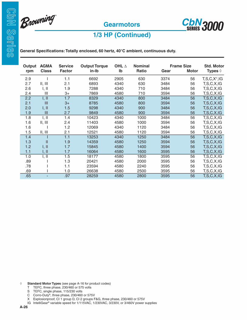
s General Specifications: Totally enclosed, 60 hertz, 40°C ambient, continuous duty.
Standard Motor Types (see page A-16 for product codes) T TEFC, three phase, 230/460 or 575 volts S TEFC, single phase, 115/230 volts C Corro-Duty®, three phase, 230/460 or 575V IG IntelliGear® variable speed for 1/115V, 1/230VAC, 3/230V, or 3/460V power supplies
Output AGMA Service Output Torque OHL ! Nominal Frame Size Std. Motor
rpm Class Factor in-lb lb Ratio Gear Motor Types
Gearmotors
1/3 HP

A-25
3000SERIESCbN
CbN
Serie
sGeneral Specifications: Totally enclosed, 60 hertz, 40°C ambient, continuous duty.
Output AGMA Service Output Torque OHL ! Nominal Frame Size Std. Motor
rpm Class Factor in-lb lb Ratio Gear Motor Types
Gearmotors
1/3 HP (Continued)
Standard Motor Types (see page A-16 for product codes) T TEFC, three phase, 230/460 or 575 volts S TEFC, single phase, 115/230 volts C Corro-Duty®, three phase, 230/460 or 575V IG IntelliGear® variable speed for 1/115VAC, 1/230VAC, 3/230V, or 3/460V power supplies
A-26
3000SERIESCbN
CbN
Serie
s General Specifications: Totally enclosed, 60 hertz, 40°C ambient, continuous duty.
Output AGMA Service Output Torque OHL ! Nominal Frame Size Std. Motor
rpm Class Factor in-lb lb Ratio Gear Motor Types
Gearmotors
1/3 HP (Continued)
Standard Motor Types (see page A-16 for product codes) T TEFC, three phase, 230/460 or 575 volts S TEFC, single phase, 115/230 volts C Corro-Duty®, three phase, 230/460 or 575V IG IntelliGear® variable speed for 1/115VAC, 1/230VAC, 3/230V, or 3/460V power supplies
A-27
3000SERIESCbN
CbN
Serie
sGeneral Specifications: Totally enclosed, 60 hertz, 40°C ambient, continuous duty.
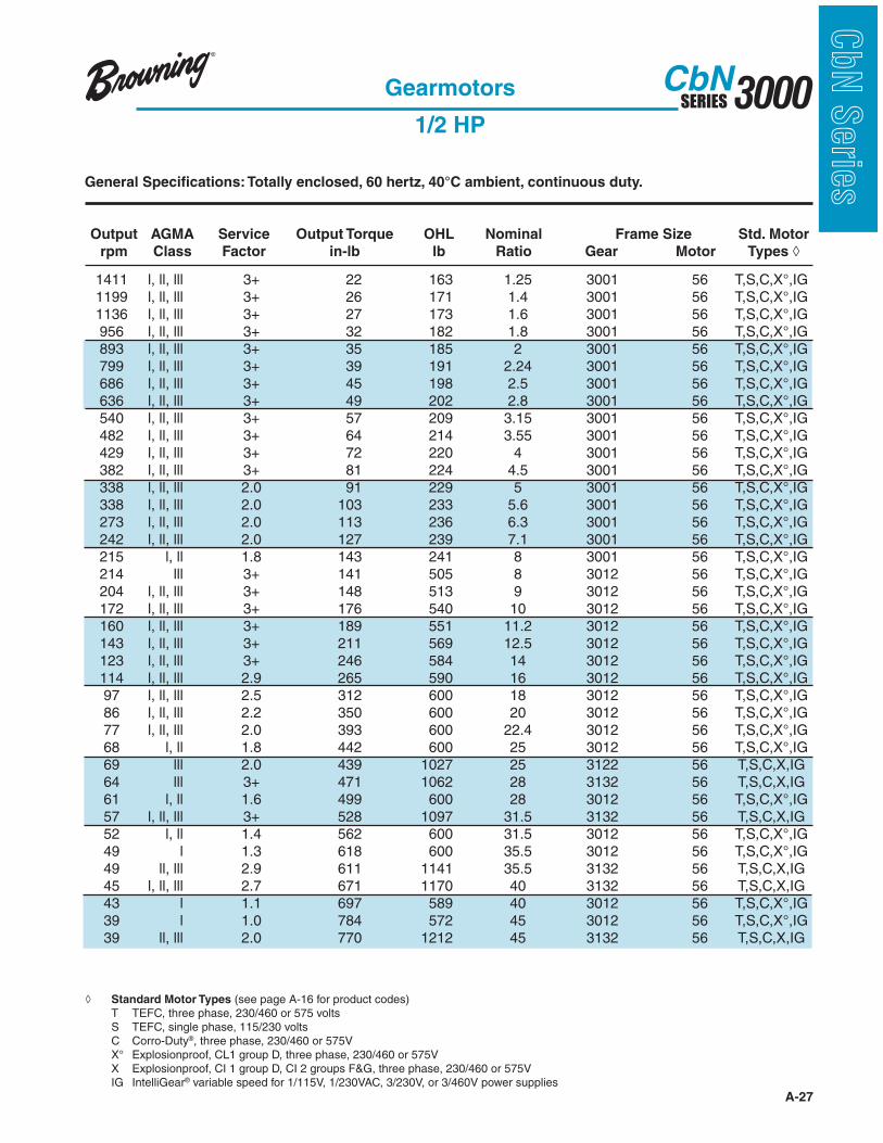
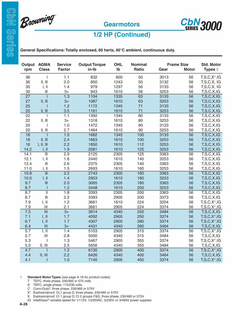
Standard Motor Types (see page A-16 for product codes) T TEFC, three phase, 230/460 or 575 volts S TEFC, single phase, 115/230 volts C Corro-Duty®, three phase, 230/460 or 575V IG IntelliGear® variable speed for 1/115V, 1/230VAC, 3/230V, or 3/460V power supplies
Output AGMA Service Output Torque OHL Nominal Frame Size Std. Motor
rpm Class Factor in-lb lb Ratio Gear Motor Types
Gearmotors
1/2 HP
A-28
3000SERIESCbN
CbN
Serie
s General Specifications: Totally enclosed, 60 hertz, 40°C ambient, continuous duty.
Output AGMA Service Output Torque OHL Nominal Frame Size Std. Motor
rpm Class Factor in-lb lb Ratio Gear Motor Types
Gearmotors
1/2 HP (Continued)
Standard Motor Types (see page A-16 for product codes) T TEFC, three phase, 230/460 or 575 volts S TEFC, single phase, 115/230 volts C Corro-Duty®, three phase, 230/460 or 575V IG IntelliGear® variable speed for 1/115V, 1/230VAC, 3/230V, or 3/460V power supplies
A-29
3000SERIESCbN
CbN
Serie
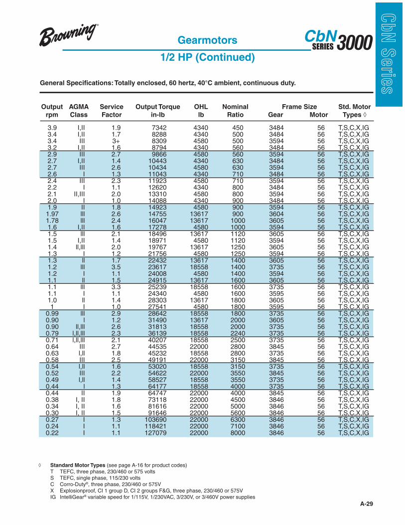
sGeneral Specifications: Totally enclosed, 60 hertz, 40°C ambient, continuous duty.
Output AGMA Service Output Torque OHL Nominal Frame Size Std. Motor
rpm Class Factor in-lb lb Ratio Gear Motor Types
Gearmotors
1/2 HP (Continued)
Standard Motor Types (see page A-16 for product codes) T TEFC, three phase, 230/460 or 575 volts S TEFC, single phase, 115/230 volts C Corro-Duty®, three phase, 230/460 or 575V IG IntelliGear® variable speed for 1/115V, 1/230VAC, 3/230V, or 3/460V power supplies

A-30
3000SERIESCbN
CbN
Serie
s General Specifications: Totally enclosed, 60 hertz, 40°C ambient, continuous duty.
Standard Motor Types (see page A-16 for product codes) T TEFC, three phase, 230/460 or 575 volts S TEFC, single phase, 115/230 volts C Corro-Duty®, three phase, 230/460 or 575V IG IntelliGear® variable speed for 1/115VAC, 1/230VAC, 3/230V, or 3/460V power supplies
Output AGMA Service Output Torque OHL Nominal Frame Size Std. Motor
rpm Class Factor in-lb lb Ratio Gear Motor Types
Gearmotors
3/4 HP
A-31
3000SERIESCbN
CbN
Serie
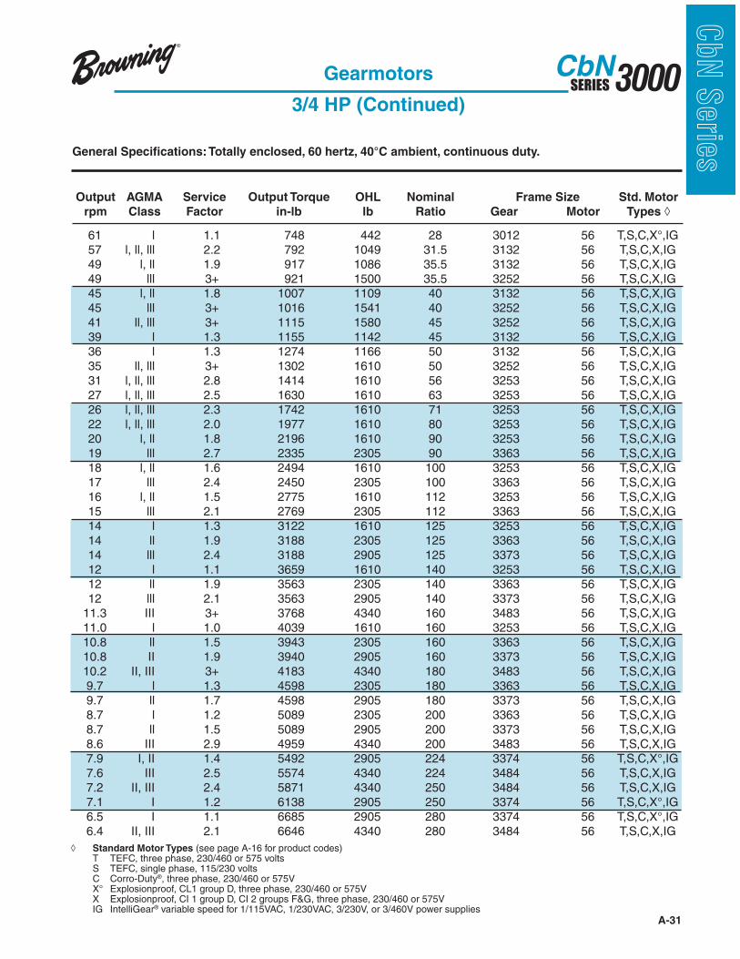
sGeneral Specifications: Totally enclosed, 60 hertz, 40°C ambient, continuous duty.
Output AGMA Service Output Torque OHL Nominal Frame Size Std. Motor
rpm Class Factor in-lb lb Ratio Gear Motor Types
Gearmotors
3/4 HP (Continued)
Standard Motor Types (see page A-16 for product codes) T TEFC, three phase, 230/460 or 575 volts S TEFC, single phase, 115/230 volts C Corro-Duty®, three phase, 230/460 or 575V IG IntelliGear® variable speed for 1/115VAC, 1/230VAC, 3/230V, or 3/460V power supplies
A-32
3000SERIESCbN
CbN
Serie
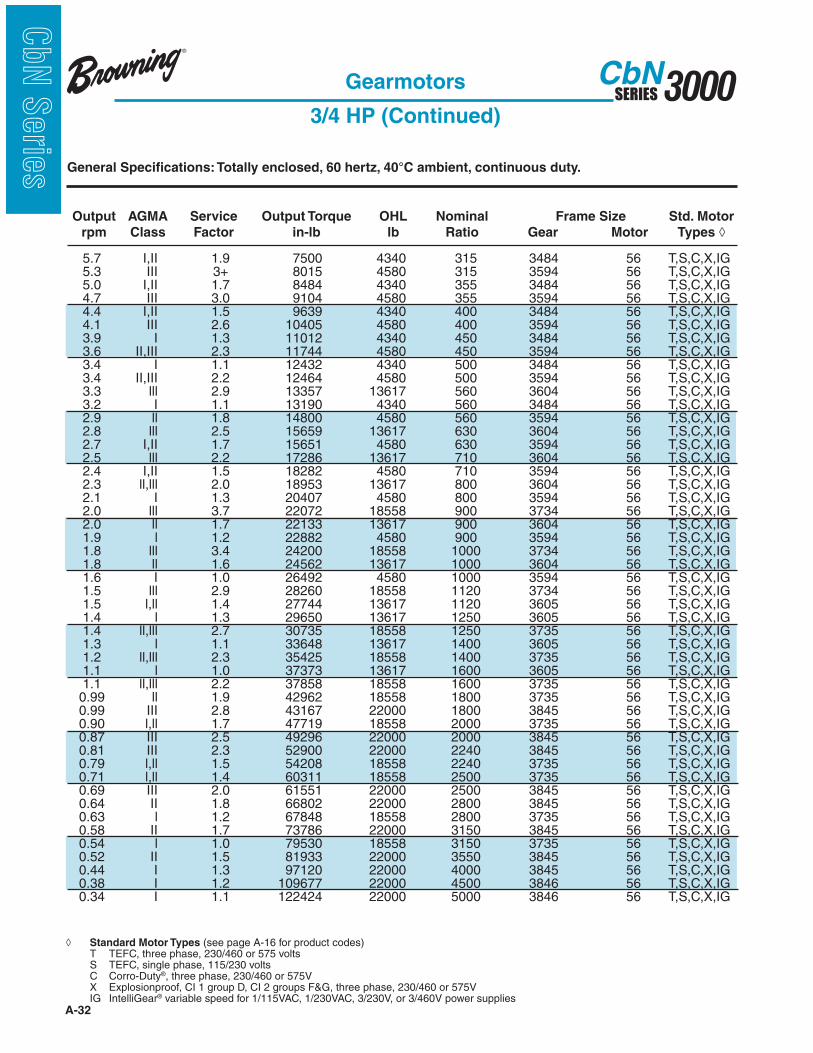
s General Specifications: Totally enclosed, 60 hertz, 40°C ambient, continuous duty.
Output AGMA Service Output Torque OHL Nominal Frame Size Std. Motor
rpm Class Factor in-lb lb Ratio Gear Motor Types
Gearmotors
3/4 HP (Continued)
Standard Motor Types (see page A-16 for product codes) T TEFC, three phase, 230/460 or 575 volts S TEFC, single phase, 115/230 volts C Corro-Duty®, three phase, 230/460 or 575V IG IntelliGear® variable speed for 1/115VAC, 1/230VAC, 3/230V, or 3/460V power supplies

A-33
3000SERIESCbN
CbN
Serie
sGeneral Specifications: Totally enclosed, 60 hertz, 40°C ambient, continuous duty.
Standard Motor Types (see page A-16 for product codes) T TEFC, three phase, 230/460 or 575 volts S TEFC, single phase, 115/230 volts C Corro-Duty®, three phase, 230/460 or 575V IG IntelliGear® variable speed for 1/230VAC, 3/230V, or 3/460V power supplies
Output AGMA Service Output Torque OHL Nominal Frame Size Std. Motor
rpm Class Factor in-lb lb Ratio Gear Motor Types
Gearmotors
1 HP

A-34
3000SERIESCbN
CbN
Serie
s General Specifications: Totally enclosed, 60 hertz, 40°C ambient, continuous duty.
Output AGMA Service Output Torque OHL Nominal Frame Size Std. Motor
rpm Class Factor in-lb lb Ratio Gear Motor Types
Gearmotors
1 HP (Continued)
Standard Motor Types (see page A-16 for product codes) T TEFC, three phase, 230/460 or 575 volts S TEFC, single phase, 115/230 volts C Corro-Duty®, three phase, 230/460 or 575V IG IntelliGear® variable speed for 1/230VAC, 3/230V, or 3/460V power supplies

A-35
3000SERIESCbN
CbN
Serie
sGeneral Specifications: Totally enclosed, 60 hertz, 40°C ambient, continuous duty.
Output AGMA Service Output Torque OHL Nominal Frame Size Std. Motor
rpm Class Factor in-lb lb Ratio Gear Motor Types
Gearmotors
1 HP (Continued)
Standard Motor Types (see page A-16 for product codes) T TEFC, three phase, 230/460 or 575 volts S TEFC, single phase, 115/230 volts C Corro-Duty®, three phase, 230/460 or 575V IG IntelliGear® variable speed for 1/230VAC, 3/230V, or 3/460V power supplies

A-36
3000SERIESCbN
CbN
Serie
s General Specifications: Totally enclosed, 60 hertz, 40°C ambient, continuous duty.
Standard Motor Types (see page A-16 for product codes) T TEFC, three phase, 230/460 or 575 volts S TEFC, single phase, 115/230 volts, 145TY C Corro-Duty®, three phase, 230/460 or 575V IG IntelliGear® variable speed for 1/230V, 3/230V, or 3/460V power supplies
Output AGMA Service Output Torque OHL Nominal Frame Size Std. Motor
rpm Class Factor in-lb lb Ratio Gear Motor Types
Gearmotors
1 1/2 HP

A-37
3000SERIESCbN
CbN
Serie
sGeneral Specifications: Totally enclosed, 60 hertz, 40°C ambient, continuous duty.
Output AGMA Service Output Torque OHL Nominal Frame Size Std. Motor
rpm Class Factor in-lb lb Ratio Gear Motor Types
Gearmotors
1 1/2 HP (Continued)
Standard Motor Types (see page A-16 for product codes) T TEFC, three phase, 230/460 or 575 volts S TEFC, single phase, 115/230 volts, 145TY C Corro-Duty®, three phase, 230/460 or 575V IG IntelliGear® variable speed for 1/230V, 3/230V, or 3/460V power supplies

A-38
3000SERIESCbN
CbN
Serie
s General Specifications: Totally enclosed, 60 hertz, 40°C ambient, continuous duty.
Output AGMA Service Output Torque OHL Nominal Frame Size Std. Motor
rpm Class Factor in-lb lb Ratio Gear Motor Types
Gearmotors
1 1/2 HP (Continued)
Standard Motor Types (see page A-16 for product codes) T TEFC, three phase, 230/460 or 575 volts S TEFC, single phase, 115/230 volts, 145TY C Corro-Duty®, three phase, 230/460 or 575V IG IntelliGear® variable speed for 1/230V, 3/230V, or 3/460V power supplies
A-39
3000SERIESCbN
CbN
Serie
sGeneral Specifications: Totally enclosed, 60 hertz, 40°C ambient, continuous duty.
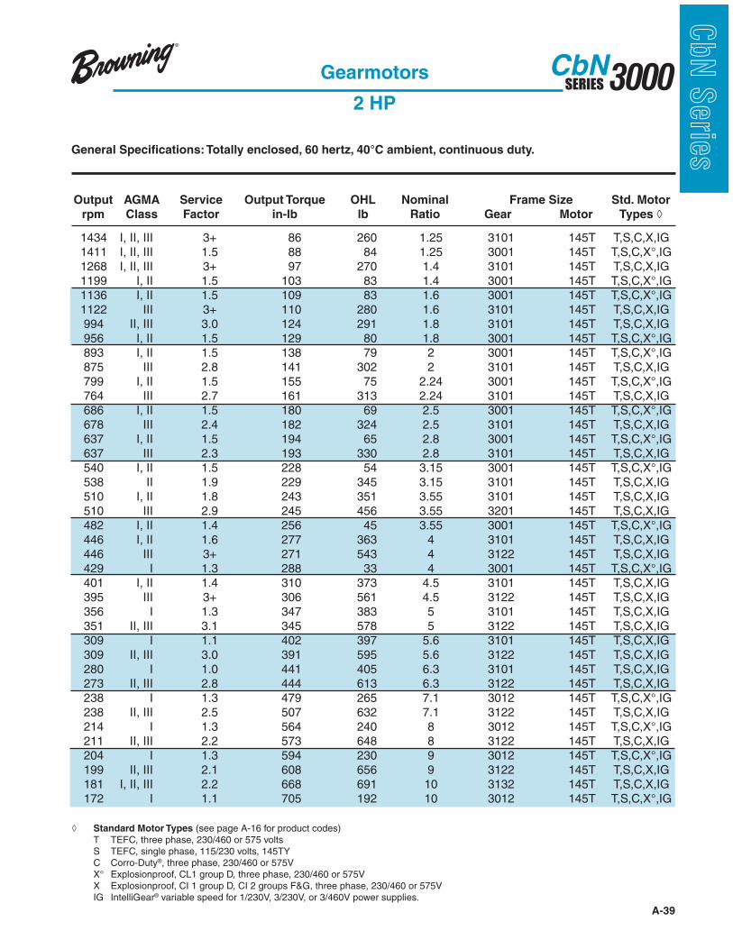
Standard Motor Types (see page A-16 for product codes) T TEFC, three phase, 230/460 or 575 volts S TEFC, single phase, 115/230 volts, 145TY C Corro-Duty®, three phase, 230/460 or 575V IG IntelliGear® variable speed for 1/230V, 3/230V, or 3/460V power supplies.
Output AGMA Service Output Torque OHL Nominal Frame Size Std. Motor
rpm Class Factor in-lb lb Ratio Gear Motor Types
Gearmotors
2 HP

A-40
3000SERIESCbN
CbN
Serie
s General Specifications: Totally enclosed, 60 hertz, 40°C ambient, continuous duty.
Output AGMA Service Output Torque OHL Nominal Frame Size Std. Motor
rpm Class Factor in-lb lb Ratio Gear Motor Types
Gearmotors
2 HP (Continued)
Standard Motor Types (see page A-16 for product codes) T TEFC, three phase, 230/460 or 575 volts S TEFC, single phase, 115/230 volts, 145TY C Corro-Duty®, three phase, 230/460 or 575V IG IntelliGear® variable speed for 1/230V, 3/230V, or 3/460V power supplies.

A-41
3000SERIESCbN
CbN
Serie
sGeneral Specifications: Totally enclosed, 60 hertz, 40°C ambient, continuous duty.
Output AGMA Service Output Torque OHL Nominal Frame Size Std. Motor
rpm Class Factor in-lb lb Ratio Gear Motor Types
Gearmotors
2 HP (Continued)
Standard Motor Types (see page A-16 for product codes) T TEFC, three phase, 230/460 or 575V S TEFC, single phase, 115/230V, 145TY C Corro-Duty®, three phase, 230/460 or 575V IG IntelliGear® variable speed for 1/230V, 3/230V, or 3/460V power supplies.
A-42
3000SERIESCbN
CbN
Serie
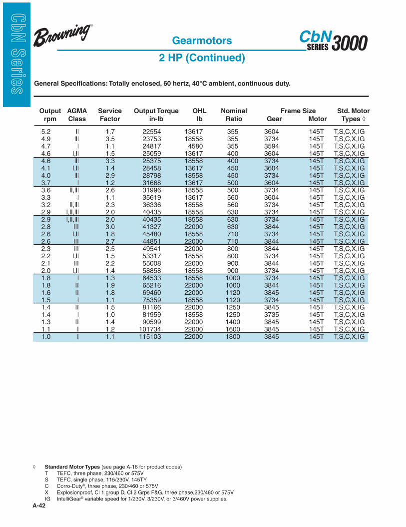
s General Specifications: Totally enclosed, 60 hertz, 40°C ambient, continuous duty.
Output AGMA Service Output Torque OHL Nominal Frame Size Std. Motor
rpm Class Factor in-lb lb Ratio Gear Motor Types
Gearmotors
2 HP (Continued)
Standard Motor Types (see page A-16 for product codes) T TEFC, three phase, 230/460 or 575V S TEFC, single phase, 115/230V, 145TY C Corro-Duty®, three phase, 230/460 or 575V IG IntelliGear® variable speed for 1/230V, 3/230V, or 3/460V power supplies.
A-43
3000SERIESCbN
CbN
Serie
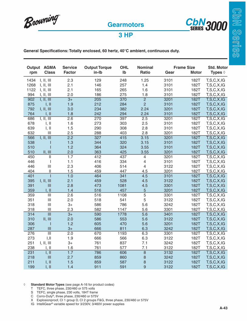
sGeneral Specifications: Totally enclosed, 60 hertz, 40°C ambient, continuous duty.
Output AGMA Service Output Torque OHL Nominal Frame Size Std. Motor
rpm Class Factor in-lb lb Ratio Gear Motor Types
Gearmotors
3 HP
Standard Motor Types (see page A-16 for product codes) T TEFC, three phase, 230/460 or 575 volts S TEFC, single phase, 230 volts, 184T frame C Corro-Duty®, three phase, 230/460 or 575V IG IntelliGear® variable speed for 3/230V, 3/460V power supplies

A-44
3000SERIESCbN
CbN
Serie
s General Specifications: Totally enclosed, 60 hertz, 40°C ambient, continuous duty.
Output AGMA Service Output Torque OHL Nominal Frame Size Std. Motor
rpm Class Factor in-lb lb Ratio Gear Motor Types
Gearmotors
3 HP (Continued)
Standard Motor Types (see page A-16 for product codes) T TEFC, three phase, 230/460 or 575 volts S TEFC, single phase, 230 volts, 184T frame C Corro-Duty®, three phase, 230/460 or 575V IG IntelliGear® variable speed for 3/230V, 3/460V power supplies

A-45
3000SERIESCbN
CbN
Serie
sGeneral Specifications: Totally enclosed, 60 hertz, 40°C ambient, continuous duty.
Output AGMA Service Output Torque OHL Nominal Frame Size Std. Motor
rpm Class Factor in-lb lb Ratio Gear Motor Types
Gearmotors
3 HP (Continued)
Standard Motor Types (see page A-16 for product codes) T TEFC, three phase, 230/460 or 575 volts S TEFC, single phase, 230 volts, 184T frame C Corro-Duty®, three phase, 230/460 or 575V IG IntelliGear® variable speed for 3/230V, 3/460V power supplies

A-46
3000SERIESCbN
CbN
Serie
s General Specifications: Totally enclosed, 60 hertz, 40°C ambient, continuous duty.
Output AGMA Service Output Torque OHL Nominal Frame Size Std. Motor
rpm Class Factor in-lb lb Ratio Gear Motor Types
Gearmotors
3 HP (Continued)
Standard Motor Types (see page A-16 for product codes) T TEFC, three phase, 230/460 or 575 volts S TEFC, single phase, 230 volts, 184T frame C Corro-Duty®, three phase, 230/460 or 575V IG IntelliGear® variable speed for 3/230V, 3/460V power supplies

A-47
3000SERIESCbN
CbN
Serie
sGeneral Specifications: Totally enclosed, 60 hertz, 40°C ambient, continuous duty.
Standard Motor Types (see page A-16 for product codes) T TEFC, three phase, 230/460 or 575 volts S TEFC, single phase, 230 volts C Corro-Duty®, three phase, 230/460 or 575V IG IntelliGear® variable speed for 3/230V, 3/460V power supplies
Output AGMA Service Output Torque OHL Nominal Frame Size Std. Motor
rpm Class Factor in-lb lb Ratio Gear Motor Types
Gearmotors
5 HP

A-48
3000SERIESCbN
CbN
Serie
s General Specifications: Totally enclosed, 60 hertz, 40°C ambient, continuous duty.
Output AGMA Service Output Torque OHL Nominal Frame Size Std. Motor
rpm Class Factor in-lb lb Ratio Gear Motor Types
Gearmotors
5 HP (Continued)
Standard Motor Types (see page A-16 for product codes) T TEFC, three phase, 230/460 or 575 volts S TEFC, single phase, 230 volts C Corro-Duty®, three phase, 230/460 or 575V IG IntelliGear® variable speed for 3/230V, 3/460V power supplies

A-49
3000SERIESCbN
CbN
Serie
sGeneral Specifications: Totally enclosed, 60 hertz, 40°C ambient, continuous duty.
Output AGMA Service Output Torque OHL Nominal Frame Size Std. Motor
rpm Class Factor in-lb lb Ratio Gear Motor Types
Gearmotors
5 HP (Continued)
Standard Motor Types (see page A-16 for product codes) T TEFC, three phase, 230/460 or 575 volts S TEFC, single phase, 230 volts C Corro-Duty®, three phase, 230/460 or 575V IG IntelliGear® variable speed for 3/230V, 3/460V power supplies

A-50
3000SERIESCbN
CbN
Serie
s General Specifications: Totally enclosed, 60 hertz, 40°C ambient, continuous duty.
Output AGMA Service Output Torque OHL Nominal Frame Size Std. Motor
rpm Class Factor in-lb lb Ratio Gear Motor Types
Gearmotors
5 HP (Continued)
Standard Motor Types (see page A-16 for product codes) T TEFC, three phase, 230/460 or 575 volts S TEFC, single phase, 230 volts C Corro-Duty®, three phase, 230/460 or 575V IG IntelliGear® variable speed for 3/230V, 3/460V power supplies

A-51
3000SERIESCbN
CbN
Serie
sGeneral Specifications: Totally enclosed, 60 hertz, 40°C ambient, continuous duty.
Standard Motor Types (see page A-16 for product codes) T TEFC, three phase, 230/460 or 575 volts C Corro-Duty®, three phase, 230/460 or 575V IG IntelliGear® variable speed for 3/460V power supplies
Output AGMA Service Output Torque OHL Nominal Frame Size Std. Motor
rpm Class Factor in-lb lb Ratio Gear Motor Types
Gearmotors
7 1/2 HP

A-52
3000SERIESCbN
CbN
Serie
s General Specifications: Totally enclosed, 60 hertz, 40°C ambient, continuous duty.
Output AGMA Service Output Torque OHL Nominal Frame Size Std. Motor
rpm Class Factor in-lb lb Ratio Gear Motor Types
Gearmotors
7 1/2 HP (Continued)
Standard Motor Types (see page A-16 for product codes) T TEFC, three phase, 208-230/460 or 575 volts C Corro-Duty®, three phase, 230/460 or 575V IG IntelliGear® variable speed for 3/460V power supplies

A-53
3000SERIESCbN
CbN
Serie
sGeneral Specifications: Totally enclosed, 60 hertz, 40°C ambient, continuous duty.
Output AGMA Service Output Torque OHL Nominal Frame Size Std. Motor
rpm Class Factor in-lb lb Ratio Gear Motor Types
Gearmotors
7 1/2 HP (Continued)
Standard Motor Types (see page A-16 for product codes) T TEFC, three phase, 230/460 or 575 volts C Corro-Duty®, three phase, 230/460 or 575V IG IntelliGear® variable speed for 3/460V power supplies† 6 pole motor
A-54
3000SERIESCbN
CbN
Serie
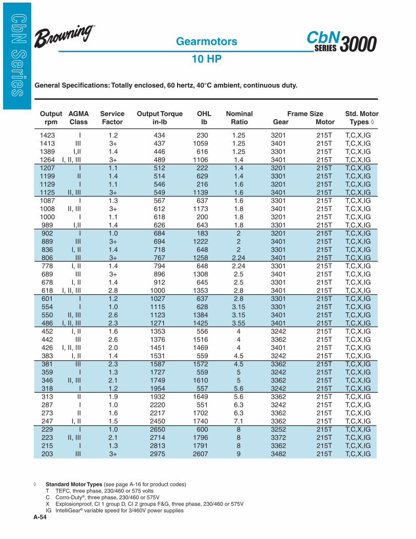
s General Specifications: Totally enclosed, 60 hertz, 40°C ambient, continuous duty.
Standard Motor Types (see page A-16 for product codes) T TEFC, three phase, 230/460 or 575 volts C Corro-Duty®, three phase, 230/460 or 575V IG IntelliGear® variable speed for 3/460V power supplies
Output AGMA Service Output Torque OHL Nominal Frame Size Std. Motor
rpm Class Factor in-lb lb Ratio Gear Motor Types
Gearmotors
10 HP
A-55
3000SERIESCbN
CbN
Serie
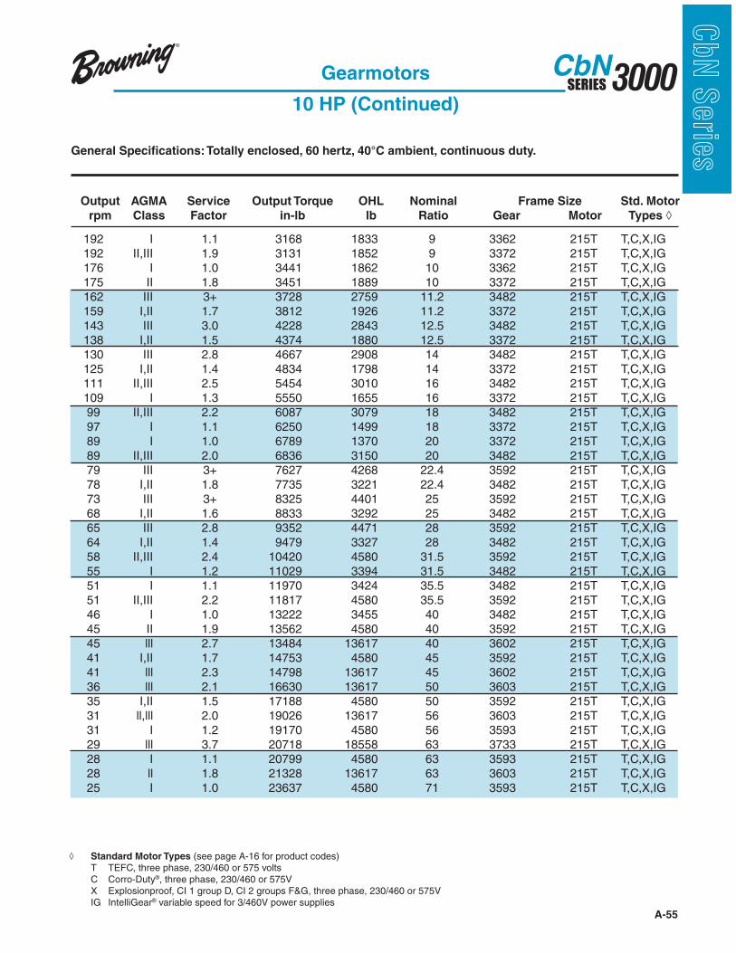
sGeneral Specifications: Totally enclosed, 60 hertz, 40°C ambient, continuous duty.
Standard Motor Types (see page A-16 for product codes) T TEFC, three phase, 230/460 or 575 volts C Corro-Duty®, three phase, 230/460 or 575V IG IntelliGear® variable speed for 3/460V power supplies
Output AGMA Service Output Torque OHL Nominal Frame Size Std. Motor
rpm Class Factor in-lb lb Ratio Gear Motor Types
Gearmotors
10 HP (Continued)

A-56
3000SERIESCbN
CbN
Serie
s General Specifications: Totally enclosed, 60 hertz, 40°C ambient, continuous duty.
Output AGMA Service Output Torque OHL Nominal Frame Size Std. Motor
rpm Class Factor in-lb lb Ratio Gear Motor Types
Gearmotors
10 HP (Continued)
Standard Motor Types (see page A-16 for product codes) T TEFC, three phase, 230/460 or 575 volts C Corro-Duty®, three phase, 230/460 or 575V IG IntelliGear® variable speed for 3/460V power supplies

A-57
3000SERIESCbN
CbN
Serie
sGeneral Specifications: Totally enclosed, 60 hertz, 40°C ambient, continuous duty.
Output AGMA Service Output Torque OHL Nominal Frame Size Std. Motor
rpm Class Factor in-lb lb Ratio Gear Motor Types
1413 I, II, III 2.6 655 1020 1.25 3401 254T T,C 1264 I, II, III 2.7 733 1063 1.4 3401 254T T,C 1125 I, II, III 2.8 824 1093 1.6 3401 254T T,C 1008 I, II, III 2.4 919 1123 1.8 3401 254T T,C 889 I, II, III 2.4 1042 1166 2 3401 254T T,C 806 I, II, III 2.3 1150 1198 2.24 3401 254T T,C 689 I, II, III 2.0 1344 1241 2.5 3401 254T T,C 618 I, II 1.9 1500 1279 2.8 3401 254T T,C 550 I, II 1.7 1684 1304 3.15 3401 254T T,C 486 I, II 1.5 1906 1321 3.55 3401 254T T,C 448 I, II, III 2.6 2028 1994 4 3482 254T T,C 442 I, II 1.7 2064 1430 4 3362 254T T,C 426 I 1.3 2176 1303 4 3401 254T T,C 400 II, III 2.8 2268 2050 4.5 3482 254T T,C 397 I 1.2 2336 1272 4.5 3401 254T T,C 381 I, II 1.5 2380 1473 4.5 3362 254T T,C 356 II, III 2.8 2548 2109 5 3482 254T T,C 346 I, II 1.4 2624 1501 5 3362 254T T,C 341 I 1.1 2718 1244 5 3401 254T T,C 319 I, II, III 2.4 2842 2164 5.6 3482 254T T,C 314 I 1.0 2950 1190 5.6 3401 254T T,C 313 I 1.2 2898 1512 5.6 3262 254T T,C 282 I, II, III 2.4 3223 2226 6.3 3482 254T T,C 273 I 1.1 3326 1426 6.3 3362 254T T,C 255 I, II, III 2.3 3558 2274 7.1 3482 254T T,C 227 III 2.6 3990 2399 8 3482 254T T,C 223 I, II 1.4 4071 1445 8 3372 254T T,C 203 II, III 2.6 4462 2459 9 3482 254T T,C 193 I 1.3 4696 1316 9 3372 254T T,C 181 II, III 2.4 5013 2518 10 3482 254T T,C 175 I 1.2 5176 1207 10 3372 254T T,C 162 II, III 2.2 5592 2573 11.2 3482 254T T,C 159 I 1.1 5718 1076 11.2 3372 254T T,C 143 II, III 2.0 6342 2632 12.5 3482 254T T,C 138 I 1.0 6561 858 12.5 3372 254T T,C 130 I, II 1.9 7001 2676 14 3482 254T T,C 125 III 3+ 7251 3570 14 3592 254T T,C 115 III 3.0 7867 3695 16 3592 254T T,C 111 I, II 1.6 8181 2738 16 3482 254T T,C 102 III 2.8 8941 3781 18 3592 254T T,C 99 I, II 1.5 9131 2775 18 3482 254T T,C 92 II, III 2.4 9891 3869 20 3592 254T T,C 89 I 1.3 10254 2809 20 3482 254T T,C
Gearmotors
15 HP
Standard Motor Types (see page A-16 for product codes) T TEFC, three phase, 230/460 or 575 volts C Corro-Duty®, three phase, 230/460 or 575V
A-58
3000SERIESCbN
CbN
Serie
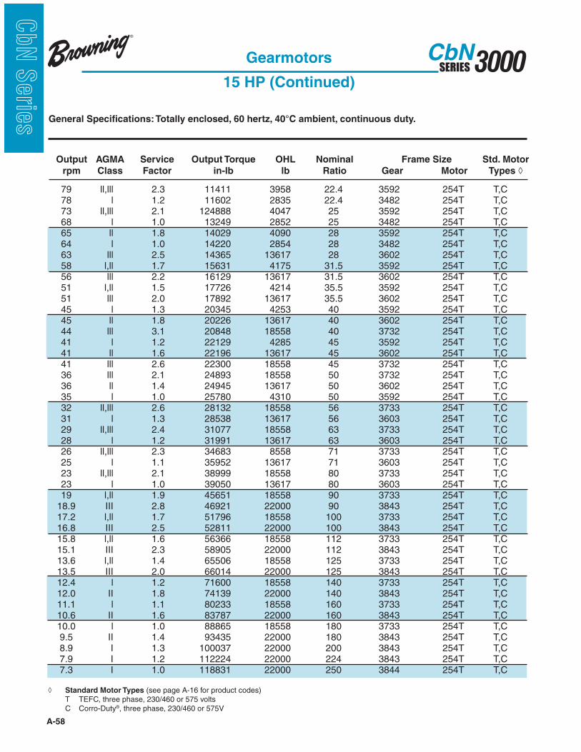
s General Specifications: Totally enclosed, 60 hertz, 40°C ambient, continuous duty.
Output AGMA Service Output Torque OHL Nominal Frame Size Std. Motor
rpm Class Factor in-lb lb Ratio Gear Motor Types
79 ll,lll 2.3 11411 3958 22.4 3592 254T T,C 78 l 1.2 11602 2835 22.4 3482 254T T,C 73 ll,lll 2.1 124888 4047 25 3592 254T T,C 68 l 1.0 13249 2852 25 3482 254T T,C 65 ll 1.8 14029 4090 28 3592 254T T,C 64 l 1.0 14220 2854 28 3482 254T T,C 63 lll 2.5 14365 13617 28 3602 254T T,C 58 l,ll 1.7 15631 4175 31.5 3592 254T T,C 56 lll 2.2 16129 13617 31.5 3602 254T T,C 51 l,ll 1.5 17726 4214 35.5 3592 254T T,C 51 lll 2.0 17892 13617 35.5 3602 254T T,C 45 l 1.3 20345 4253 40 3592 254T T,C 45 ll 1.8 20226 13617 40 3602 254T T,C 44 lll 3.1 20848 18558 40 3732 254T T,C 41 l 1.2 22129 4285 45 3592 254T T,C 41 ll 1.6 22196 13617 45 3602 254T T,C 41 lll 2.6 22300 18558 45 3732 254T T,C 36 lll 2.1 24893 18558 50 3732 254T T,C 36 ll 1.4 24945 13617 50 3602 254T T,C 35 l 1.0 25780 4310 50 3592 254T T,C 32 ll,lll 2.6 28132 18558 56 3733 254T T,C 31 l 1.3 28538 13617 56 3603 254T T,C 29 ll,lll 2.4 31077 18558 63 3733 254T T,C 28 l 1.2 31991 13617 63 3603 254T T,C 26 ll,lll 2.3 34683 8558 71 3733 254T T,C 25 l 1.1 35952 13617 71 3603 254T T,C 23 ll,lll 2.1 38999 18558 80 3733 254T T,C 23 l 1.0 39050 13617 80 3603 254T T,C 19 l,ll 1.9 45651 18558 90 3733 254T T,C 18.9 III 2.8 46921 22000 90 3843 254T T,C 17.2 l,ll 1.7 51796 18558 100 3733 254T T,C 16.8 III 2.5 52811 22000 100 3843 254T T,C 15.8 l,ll 1.6 56366 18558 112 3733 254T T,C 15.1 III 2.3 58905 22000 112 3843 254T T,C 13.6 l,ll 1.4 65506 18558 125 3733 254T T,C 13.5 III 2.0 66014 22000 125 3843 254T T,C 12.4 l 1.2 71600 18558 140 3733 254T T,C 12.0 II 1.8 74139 22000 140 3843 254T T,C 11.1 l 1.1 80233 18558 160 3733 254T T,C 10.6 II 1.6 83787 22000 160 3843 254T T,C 10.0 l 1.0 88865 18558 180 3733 254T T,C 9.5 II 1.4 93435 22000 180 3843 254T T,C 8.9 I 1.3 100037 22000 200 3843 254T T,C 7.9 I 1.2 112224 22000 224 3843 254T T,C 7.3 I 1.0 118831 22000 250 3844 254T T,C
Gearmotors
15 HP (Continued)
Standard Motor Types (see page A-16 for product codes) T TEFC, three phase, 230/460 or 575 volts C Corro-Duty®, three phase, 230/460 or 575V
A-59
3000SERIESCbN
CbN
Serie
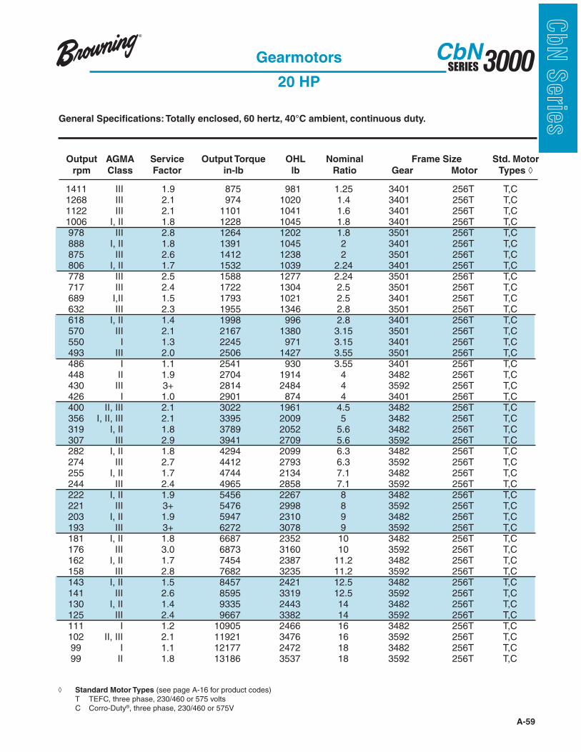
sGeneral Specifications: Totally enclosed, 60 hertz, 40°C ambient, continuous duty.
Output AGMA Service Output Torque OHL Nominal Frame Size Std. Motor
rpm Class Factor in-lb lb Ratio Gear Motor Types
1411 III 1.9 875 981 1.25 3401 256T T,C 1268 III 2.1 974 1020 1.4 3401 256T T,C 1122 III 2.1 1101 1041 1.6 3401 256T T,C 1006 I, II 1.8 1228 1045 1.8 3401 256T T,C 978 III 2.8 1264 1202 1.8 3501 256T T,C 888 I, II 1.8 1391 1045 2 3401 256T T,C 875 III 2.6 1412 1238 2 3501 256T T,C 806 I, II 1.7 1532 1039 2.24 3401 256T T,C 778 III 2.5 1588 1277 2.24 3501 256T T,C 717 III 2.4 1722 1304 2.5 3501 256T T,C 689 I,II 1.5 1793 1021 2.5 3401 256T T,C 632 III 2.3 1955 1346 2.8 3501 256T T,C 618 I, II 1.4 1998 996 2.8 3401 256T T,C 570 III 2.1 2167 1380 3.15 3501 256T T,C 550 I 1.3 2245 971 3.15 3401 256T T,C 493 III 2.0 2506 1427 3.55 3501 256T T,C 486 I 1.1 2541 930 3.55 3401 256T T,C 448 II 1.9 2704 1914 4 3482 256T T,C 430 III 3+ 2814 2484 4 3592 256T T,C 426 I 1.0 2901 874 4 3401 256T T,C 400 II, III 2.1 3022 1961 4.5 3482 256T T,C 356 I, II, III 2.1 3395 2009 5 3482 256T T,C 319 I, II 1.8 3789 2052 5.6 3482 256T T,C 307 III 2.9 3941 2709 5.6 3592 256T T,C 282 I, II 1.8 4294 2099 6.3 3482 256T T,C 274 III 2.7 4412 2793 6.3 3592 256T T,C 255 I, II 1.7 4744 2134 7.1 3482 256T T,C 244 III 2.4 4965 2858 7.1 3592 256T T,C 222 I, II 1.9 5456 2267 8 3482 256T T,C 221 III 3+ 5476 2998 8 3592 256T T,C 203 I, II 1.9 5947 2310 9 3482 256T T,C 193 III 3+ 6272 3078 9 3592 256T T,C 181 I, II 1.8 6687 2352 10 3482 256T T,C 176 III 3.0 6873 3160 10 3592 256T T,C 162 I, II 1.7 7454 2387 11.2 3482 256T T,C 158 III 2.8 7682 3235 11.2 3592 256T T,C 143 I, II 1.5 8457 2421 12.5 3482 256T T,C 141 III 2.6 8595 3319 12.5 3592 256T T,C 130 I, II 1.4 9335 2443 14 3482 256T T,C 125 III 2.4 9667 3382 14 3592 256T T,C 111 I 1.2 10905 2466 16 3482 256T T,C 102 II, III 2.1 11921 3476 16 3592 256T T,C 99 I 1.1 12177 2472 18 3482 256T T,C 99 II 1.8 13186 3537 18 3592 256T T,C
Gearmotors
20 HP
Standard Motor Types (see page A-16 for product codes) T TEFC, three phase, 230/460 or 575 volts C Corro-Duty®, three phase, 230/460 or 575V

A-60
3000SERIESCbN
CbN
Serie
s General Specifications: Totally enclosed, 60 hertz, 40°C ambient, continuous duty.
Output AGMA Service Output Torque OHL Nominal Frame Size Std. Motor
rpm Class Factor in-lb lb Ratio Gear Motor Types
Gearmotors
20 HP (Continued)
Standard Motor Types (see page A-16 for product codes) T TEFC, three phase, 230/460 or 575 volts C Corro-Duty®, three phase, 230/460 or 575V
92 II,III 2.0 13186 3594 20 3592 256T T, C 89 l 1.0 13670 2468 20 3482 256T T, C 80 lll 2.3 15143 12709 22.4 3602 256T T, C 79 I,II 1.7 15254 3647 22.4 3592 256T T, C 73 I,II 1.6 16651 3692 25 3592 256T T, C 69 lll 2.0 17633 13087 25 3602 256T T, C 65 I,II 1.4 18704 3710 28 3592 256T T, C 63 ll 1.9 19154 13288 28 3602 256T T, C 62 lll 3.9 19638 18558 28 3732 256T T, C 58 l 1.3 20841 3732 31.5 3592 256T T, C 56 ll 1.7 21505 13550 31.5 3602 256T T, C 55 lll 3.4 21989 18558 31.5 3732 256T T, C 51 l 1.1 23635 3733 35.5 3592 256T T, C 51 ll 1.5 23856 13617 35.5 3602 256T T, C 49 lll 2.8 24893 18558 35.5 3732 256T T, C 45 - 0.97 27127 3722 40 3592 256T T, C 45 l,ll 1.4 26967 13617 40 3602 256T T, C 44 lll 2.4 27797 18558 40 3732 256T T, C 41 l 1.2 29595 13617 45 3602 256T T, C 41 ll 1.9 29733 18558 45 3732 256T T, C 41 lll 2.2 28979 18558 45 3733 256T T, C 36 l 1.1 33260 13617 50 3602 256T T, C 36 ll 1.6 33191 18558 50 3732 256T T, C 36 lll 2.1 32499 18558 50 3733 256T T, C 32 l,ll,lll 2.2 33041 18558 56 3733 256T T, C 29 l,ll,lll 2.0 37510 18558 63 3733 256T T, C 26 l,ll 1.9 41437 18558 71 3733 256T T, C 24 lll 2.0 46244 12000 71 3843 256T T, C 23 l,ll 1.7 48952 18558 80 3733 256T T, C 21 III 2.4 55452 22000 80 3843 256T T, C 19.5 l,ll 1.4 60868 18558 90 3733 256T T, C 18.9 III 2.1 62561 22000 90 3843 256T T, C 17.2 l 1.3 69061 18558 100 3733 256T T, C 16.8 II,III 1.9 70415 22000 100 3843 256T T, C 15.8 l 1.2 75155 18558 112 3733 256T T, C 15.1 II 1.7 78540 22000 112 3843 256T T, C 13.6 l 1.0 87342 18558 125 3733 256T T, C 13.5 II 1.5 88019 22000 125 3843 256T T, C 12.0 I, II 1.4 98852 22000 140 3843 256T T, C 10.6 I 1.2 111716 22000 160 3843 256T T, C 9.5 I 1.1 124581 22000 180 3843 256T T, C 8.9 I 1.0 133383 22000 200 3843 256T T, C

A-61
3000SERIESCbN
CbN
Serie
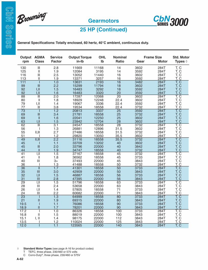
sGeneral Specifications: Totally enclosed, 60 hertz, 40°C ambient, continuous duty.
Output AGMA Service Output Torque OHL Nominal Frame Size Std. Motor
rpm Class Factor in-lb lb Ratio Gear Motor Types
Gearmotors
25 HP
Standard Motor Types (see page A-16 for product codes) T TEFC, three phase, 230/460 or 575 volts C Corro-Duty®, three phase, 230/460 or 575V
1411 I, II 1.5 1094 827 1.25 3401 284T T,C 1367 III 2.5 1129 1062 1.25 3501 284T T,C 1268 I, II 1.7 1218 827 1.4 3401 284T T,C 1199 III 2.4 1288 1101 1.4 3501 284T T,C 1122 I, II 1.7 1376 822 1.6 3401 284T T,C 1094 III 2.3 1412 1128 1.6 3501 284T T,C 1006 I, II 1.4 1535 811 1.8 3401 284T T,C 978 III 2.2 1579 1161 1.8 3501 284T T,C 888 I, II 1.5 1738 788 2 3401 284T T,C 875 III 2.1 1765 1194 2 3501 284T T,C 806 I, II 1.4 1915 763 2.24 3401 284T T,C 778 III 2.0 1985 1228 2.24 3501 284T T,C 717 I, II 1.9 2153 1252 2.5 3501 284T T,C 689 I 1.2 2241 715 2.5 3401 284T T,C 632 I, II 1.9 2444 1288 2.8 3501 284T T,C 618 I 1.1 2497 660 2.8 3401 284T T,C 570 I, II 1.7 2709 1286 3.15 3501 284T T,C 550 I 1.0 2806 614 3.15 3401 284T T,C 545 III 3.0+ 2832 7440 3.15 3602 284T T,C 493 I, II 1.6 3132 1259 3.55 3501 284T T,C 480 III 3.0+ 3905 7431 3.55 3602 284T T,C 486 n/a 0.91 3176 540 3.55 3401 284T T,C 448 I, II 1.6 3380 1834 4 3482 284T T,C 430 III 3+ 3518 2421 4 3592 284T T,C 400 I, II 1.7 3777 1872 4.5 3482 284T T,C 376 III 3+ 4028 2488 4.5 3592 284T T,C 356 I, II 1.7 4244 1909 5 3482 284T T,C 343 III 3.0 4408 2557 5 3592 284T T,C 319 I, II 1.4 4737 1940 5.6 3482 284T T,C 307 III 2.3 4927 2621 5.6 3592 284T T,C 282 I, II 1.5 5368 1973 6.3 3482 284T T,C 274 III 2.2 5515 2693 6.3 3592 284T T,C 255 I, II 1.4 5929 1994 7.1 3482 284T T,C 244 III 2.0 6206 2749 7.1 3592 284T T,C 222 I, II 1.5 6820 2134 8 3482 284T T,C 221 III 3.0 6846 2892 8 3592 284T T,C 203 I, II 1.5 7433 2162 9 3482 284T T,C 193 III 2.6 7840 2959 9 3592 284T T,C 181 I, II 1.4 8358 2185 10 3482 284T T,C 176 III 2.4 8592 3025 10 3592 284T T,C 162 I 1.3 9318 2201 11.2 3482 284T T,C 158 II, III 2.2 9603 3085 11.2 3592 284T T,C 143 I 1.2 10571 2210 12.5 3482 284T T,C 141 II, III 2.1 10744 3149 12.5 3592 284T T,C 130 I 1.1 11669 2210 14 3482 284T T,C
A-62
3000SERIESCbN
CbN
Serie
s General Specifications: Totally enclosed, 60 hertz, 40°C ambient, continuous duty.
Output AGMA Service Output Torque OHL Nominal Frame Size Std. Motor
rpm Class Factor in-lb lb Ratio Gear Motor Types
Gearmotors
25 HP (Continued)
Standard Motor Types (see page A-16 for product codes) T TEFC, three phase, 230/460 or 575 volts C Corro-Duty®, three phase, 230/460 or 575V
130 lll 2.8 11669 11168 14 3602 284T T, C 125 II 1.9 12084 3195 14 3592 284T T, C 116 lll 2.5 13052 11440 16 3602 284T T, C 113 II 1.9 13371 3257 16 3592 284T T, C 111 I 1.0 13631 2193 16 3482 284T T, C 99 lll 2.2 15299 11794 18 3602 284T T, C 92 I,II 1.5 16483 3292 18 3592 284T T, C 92 I,II 1.6 16483 3320 20 3592 284T T, C 88 lll 2.0 17287 12068 20 3602 284T T, C 80 ll 1.8 18929 12248 22.4 3602 284T T, C 79 I,II 1.4 19067 3336 22.4 3592 284T T, C 77 lll 3.8 19534 18558 22.4 3732 284T T, C 73 I 1.2 20813 3337 25 3592 284T T, C 69 lll 3.4 21781 18558 25 3732 284T T, C 69 ll 1.6 22041 12250 25 3602 284T T, C 63 l,ll 1.5 23942 12704 28 3602 284T T, C 62 lll 3.1 24547 18558 28 3732 284T T, C 56 l 1.3 26881 12896 31.5 3602 284T T, C 55 ll,lll 2.7 27486 18558 31.5 3732 284T T, C 51 l 1.2 29820 13050 35.5 3602 284T T, C 49 ll,lll 2.2 31116 18558 35.5 3732 284T T, C 45 l 1.1 33709 13202 40 3602 284T T, C 45 lll 2.0 33796 22000 40 3842 284T T, C 44 ll 1.9 34747 18558 40 3732 284T T, C 41 l,ll 1.5 37167 18558 45 3732 284T T, C 41 ll 1.8 36562 18558 45 3733 284T T, C 40 III 3+ 37493 22000 45 3843 284T T, C 36 l 1.3 41488 18558 50 3732 284T T, C 36 ll 1.7 41301 18558 50 3733 284T T, C 35 III 3.0 42909 22000 50 3843 284T T, C 32 l,ll 1.5 46887 18558 56 3733 284T T, C 31 III 2.8 47395 22000 56 3843 284T T, C 29 l,ll 1.5 51796 18558 63 3733 284T T, C 28 III 2.4 53658 22000 63 3843 284T T, C 26 l,ll 1.4 57805 18558 71 3733 284T T, C 24 III 2.2 60682 22000 71 3843 284T T, C 23 l 1.3 64999 18558 80 3733 284T T, C 21 II 1.9 69315 22000 80 3843 284T T, C 19.5 l 1.1 76086 18558 90 3733 284T T, C 18.9 II 1.7 78201 22000 90 3843 284T T, C 17.2 l 1.0 86326 18558 100 3733 284T T, C 16.8 II 1.5 88019 22000 100 3843 284T T, C 15.1 I, II 1.4 98175 22000 112 3843 284T T, C 13.5 I 1.2 110024 22000 125 3843 284T T, C 12.0 I 1.1 123565 22000 140 3843 284T T, C

A-63
3000SERIESCbN
CbN
Serie
sGeneral Specifications: Totally enclosed, 60 hertz, 40°C ambient, continuous duty.
Output AGMA Service Output Torque OHL Nominal Frame Size Std. Motor
rpm Class Factor in-lb lb Ratio Gear Motor Types
Gearmotors
30 HP
Standard Motor Types (see page A-16 for product codes) T TEFC, three phase, 230/460 or 575 volts C Corro-Duty®, three phase, 230/460 or 575V
1411 I 1.3 1313 638 1.25 3401 286T T, C 1389 II,III 2.1 1334 1030 1.25 3501 286T T, C 1268 I,II 1.4 1461 621 1.4 3401 286T T, C 1199 III 2.0 1546 1066 1.4 3501 286T T, C 1122 I,II 1.4 1652 603 1.6 3401 286T T, C 1094 I,II 1.9 1694 1091 1.6 3501 286T T, C 1006 I 1.2 1842 577 1.8 3401 286T T, C 978 I,II 1.8 1895 1112 1.8 3501 286T T, C 888 I 1.2 2086 530 2 3401 286T T, C 875 I,II 1.8 2118 1112 2 3501 286T T, C 806 I 1.1 2298 486 2.24 3401 286T T, C 778 I,II 1.7 2382 1104 2.24 3501 286T T, C 717 I,II 1.6 2584 1095 2.5 3501 286T T, C 689 I 1.0 2689 409 2.5 3401 286T T, C 648 I,II 1.6 2859 1070 2.8 3501 286T T, C 618 N/A 0.95 2996 325 2.8 3401 286T T, C 570 I,II 1.4 3251 1041 3.15 3501 286T T, C 545 III 3.0+ 3290 7030 3.15 3602 286T T, C 493 I,II 1.4 3759 984 3.55 3501 286T T, C 480 III 3.0+ 3730 7025 3.55 3602 286T T, C 448 I 1.3 4055 1755 4 3482 286T T, C 430 III 2.8 4221 2358 4 3592 286T T, C 400 I,II 1.4 4533 1783 4.5 3482 286T T, C 376 III 2.6 4833 2418 4.5 3592 286T T, C 356 I,II 1.4 5093 1809 5 3482 286T T, C 343 III 2.5 5290 2478 5 3592 286T T, C 319 I 1.2 5684 1829 5.6 3482 286T T, C 307 II 1.9 5912 2533 5.6 3592 286T T, C 282 I 1.2 6441 1846 6.3 3482 286T T, C 274 II 1.8 6617 2594 6.3 3592 286T T, C 255 I 1.1 7115 1854 7.1 3482 286T T, C 244 II 1.6 7447 2639 7.1 3592 286T T, C 222 I 1.3 8184 2001 8 3482 286T T, C 221 II,III 2.5 8215 2785 8 3592 286T T, C 203 I 1.3 8920 2013 9 3482 286T T, C 193 II,III 2.2 9408 2839 9 3592 286T T, C 181 I 1.2 10030 2018 10 3482 286T T, C 176 II,III 2.0 10310 2891 10 3592 286T T, C 162 I 1.1 11181 2015 11.2 3482 286T T, C 158 II 1.9 11523 2935 11.2 3592 286T T, C 161 lll 2.8 11306 10438 11.2 3602 286T T, C 145 lll 2.6 12550 10647 12.5 3602 286T T, C 143 I 1.0 12685 1999 12.5 3482 286T T, C 141 II 1.7 12893 2979 12.5 3592 286T T, C 130 N/A 0.93 14002 1977 14 3482 286T T, C

A-64
3000SERIESCbN
CbN
Serie
s General Specifications: Totally enclosed, 60 hertz, 40°C ambient, continuous duty.
Output AGMA Service Output Torque OHL Nominal Frame Size Std. Motor
rpm Class Factor in-lb lb Ratio Gear Motor Types
Gearmotors
30 HP (Continued)
Standard Motor Types (see page A-34 for product codes) T TEFC, three phase, 208-230/460 or 575 volts C Corro-Duty®, three phase, 230/460 or 575V
130 lll 2.3 14002 10682 14 3602 286T T, C 125 I,II 1.6 14500 3007 14 3592 286T T, C 116 lll 2.1 15662 11121 16 3602 286T T, C 115 I,II 1.4 15783 3038 16 3592 286T T, C 102 I 1.3 17882 3048 18 3592 286T T, C 99 lll 1.8 18359 11421 18 3602 286T T, C 98 lll 3.9 18462 18558 18 3732 286T T, C 92 I 1.3 19780 3045 20 3592 286T T, C 88 lll 1.6 20744 11645 20 3602 286T T, C 87 lll 3.5 20848 18558 20 3732 286T T, C 80 lll 1.5 22715 11788 22.4 3602 286T T, C 79 I 1.1 22881 3026 22.4 3592 286T T, C 77 lll 3.1 23441 18558 22.4 3732 286T T, C 73 I 1.0 24976 2764 25 3592 286T T, C 69 ll,lll 2.9 26138 18558 25 3732 286T T, C 69 l 1.3 26449 12014 25 3602 286T T, C 63 l 1.2 28731 12120 28 3602 286T T, C 62 ll,lll 2.6 29457 18558 28 3732 286T T, C 56 l 1.1 32257 12241 31.5 3602 286T T, C 55 ll,lll 2.3 32983 18558 31.5 3732 286T T, C 51 l 1.0 35784 12323 35.5 3602 286T T, C 51 l 1.0 35784 12323 35.5 3602 286T T, C 51 III 2.2 35888 22000 35.5 3842 286T T, C 49 ll 1.8 37340 18558 35.5 3732 286T T, C 45 II 1.7 40555 22000 40 3842 286T T, C 44 l,ll 1.6 41696 18558 40 3732 286T T, C 44 III 3+ 40218 22000 40 3843 286T T, C 41 l 1.3 44600 18558 45 3732 286T T, C 41 II 1.5 43874 18558 45 3733 286T T, C 40 III 2.9 44991 22000 45 3843 286T T, C 36 l 1.1 49786 18558 50 3732 286T T, C 36 ll 1.4 49561 18558 50 3733 286T T, C 35 III 2.5 51491 22000 50 3843 286T T, C 32 l 1.3 56264 18558 56 3733 286T T, C 31 II,III 2.3 56874 22000 56 3843 286T T, C 29 l 1.2 62155 18558 63 3733 286T T, C 28 II, III 2.0 64389 22000 63 3843 286T T, C 26 l 1.1 69366 18558 71 3733 286T T, C 24 II 1.8 72819 22000 71 3843 286T T, C 23 I 1.1 77998 18558 80 3733 286T T, C 21 II 1.6 83178 22000 80 3843 286T T, C 19 I, II 1.4 93842 22000 90 3843 286T T, C 17 I 1.3 105623 22000 100 3843 286T T, C 15 I 1.1 117810 22000 112 3843 286T T, C 13 I 1.0 132028 22000 125 3843 286T T, C
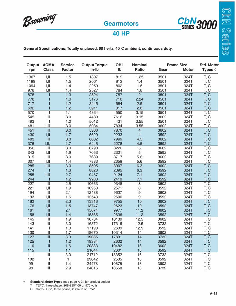
A-65
3000SERIESCbN
CbN
Serie
sGeneral Specifications: Totally enclosed, 60 hertz, 40°C ambient, continuous duty.
Output AGMA Service Output Torque OHL Nominal Frame Size Std. Motor
rpm Class Factor in-lb lb Ratio Gear Motor Types
Gearmotors
40 HP
Standard Motor Types (see page A-34 for product codes) T TEFC, three phase, 208-230/460 or 575 volts C Corro-Duty®, three phase, 230/460 or 575V
1367 I,II 1.5 1807 819 1.25 3501 324T T, C 1199 I,II 1.5 2061 812 1.4 3501 324T T, C 1094 I,II 1.4 2259 802 1.6 3501 324T T, C 978 I,II 1.4 2527 784 1.8 3501 324T T, C 875 I 1.3 2824 757 2 3501 324T T, C 778 I 1.3 3176 718 2.24 3501 324T T, C 717 I 1.2 3445 684 2.5 3501 324T T, C 632 I 1.2 3911 317 2.8 3501 324T T, C 570 I 1.1 4334 550 3.15 3501 324T T, C 545 ll,lll 3.0 4439 7616 3.15 3602 324T T, C 493 I 1.0 5012 431 3.55 3501 324T T, C 481 ll,lll 3.0 5034 7834 3.55 3602 324T T, C 451 lll 3.0 5366 7870 4 3602 324T T, C 430 I,II 1.7 5629 2233 4 3592 324T T, C 403 lll 3.0 6002 7999 4.5 3602 324T T, C 376 I,II, 1.7 6445 2278 4.5 3592 324T T, C 356 lll 3.0 6790 8226 5 3602 324T T, C 343 I,II 1.9 7053 2321 5 3592 324T T, C 315 lll 3.0 7689 8717 5.6 3602 324T T, C 307 I,II 1.4 7883 2358 5.6 3592 324T T, C 285 ll,lll 3.0 8505 8907 6.3 3602 324T T, C 274 I 1.3 8823 2395 6.3 3592 324T T, C 255 ll,lll 2.7 9487 9124 7.1 3602 324T T, C 244 I 1.2 9930 2419 7.1 3592 324T T, C 227 lll 2.5 10663 9348 8 3602 324T T, C 221 I,II 1.9 10953 2571 8 3592 324T T, C 194 lll 2.1 12488 9637 9 3602 324T T, C 193 I,II 1.6 12543 2600 9 3592 324T T, C 182 lll 2.3 13318 9755 10 3602 324T T, C 176 I,II 1.5 13747 2623 10 3592 324T T, C 161 lll 2.1 15074 9977 11.2 3602 324T T, C 158 I,II 1.4 15365 2636 11.2 3592 324T T, C 145 ll 1.9 16734 10139 12.5 3602 324T T, C 143 lll 3.0 16872 17316 12.5 3732 324T T, C 141 l 1.3 17190 2639 12.5 3592 324T T, C 130 ll 1.7 18670 10314 14 3602 324T T, C 127 lll 3.0 19085 17831 14 3732 324T T, C 125 I 1.2 19334 2632 14 3592 324T T, C 116 ll 1.6 20883 10482 16 3602 324T T, C 115 I 1.1 21044 2601 16 3592 324T T, C 111 lll 3.0 21712 18352 16 3732 324T T, C 102 I 1 23842 2535 18 3592 324T T, C 99 ll 1.4 24478 10675 18 3602 324T T, C 98 lll 2.9 24616 18558 18 3732 324T T, C

A-66
3000SERIESCbN
CbN
Serie
s General Specifications: Totally enclosed, 60 hertz, 40°C ambient, continuous duty.
Output AGMA Service Output Torque OHL Nominal Frame Size Std. Motor
rpm Class Factor in-lb lb Ratio Gear Motor Types
Gearmotors
40 HP (Continued)
88 l 1.2 27659 10799 20 3602 324T T, C 87 ll,lll 2.6 27797 18558 20 3732 324T T, C 80 l 1.1 30287 10866 22.4 3602 324T T, C 77 ll,lll 2.4 31255 18558 22.4 3732 324T T, C 69 ll,lll 2.1 34850 18558 25 3732 324T T, C 69 l 1.0 35265 10940 25 3602 324T T, C 62 ll 1.9 39276 18558 28 3732 324T T, C 63 III 2.6 38169 22000 28 3842 324T T, C 62 I, II 1.9 39276 18558 28 3732 324T T, C 57 III 2.3 42733 22000 31.5 3842 324T T, C 55 l,ll 1.7 43978 18558 31.5 3732 324T T, C 55 III 3.0 42926 22000 31.5 3843 324T T, C 51 III 1.7 47850 22000 35.5 3842 324T T, C 50 III 2.7 47801 22000 35.5 3843 324T T, C 49 I, II 1.4 49786 18558 35.5 3732 324T T, C 45 I 1.3 54073 22000 40 3842 324T T, C 44 l 1.2 55595 18558 40 3732 324T T, C 44 II, III 2.4 53624 22000 40 3843 324T T, C 41 l 1.1 58499 18558 45 3733 324T T, C 40 III 2.2 59988 22000 45 3843 324T T, C 36 l 1.0 66082 18558 45 3733 324T T, C 35 II 1.9 68655 22000 50 3843 324T T, C 31 I, II 1.7 75832 22000 56 3843 324T T, C 28 I, II 1.5 85852 22000 63 3843 324T T, C 24 I, II 1.4 97092 22000 71 3843 324T T, C 21 I 1.2 110904 22000 80 3843 324T T, C 19 I 1.1 125122 22000 90 3843 324T T, C
Standard Motor Types (see page A-34 for product codes) T TEFC, three phase, 208-230/460 or 575 volts C Corro-Duty®, three phase, 230/460 or 575V IG IntelliGear® variable speed for 3/460V power supplies

A-67
3000SERIESCbN
CbN
Serie
sGeneral Specifications: Totally enclosed, 60 hertz, 40°C ambient, continuous duty.
Output AGMA Service Output Torque OHL Nominal Frame Size Std. Motor
rpm Class Factor in-lb lb Ratio Gear Motor Types
Gearmotors
50 HP
545 I,II,III 2.4 5549 7482 3.15 3602 326T T, C 481 I,II,III 2.4 6292 7684 3.55 3602 326T T, C 451 I,II,III 2.4 6707 7837 4 3602 326T T, C 403 I,II,III 2.4 7502 8043 4.5 3602 326T T, C 356 I,II,III 2.4 8488 8261 5 3602 326T T, C 315 I,II,III 2.4 9611 8482 5.6 3602 326T T, C 285 I,II,III 2.4 10631 8648 6.3 3602 326T T, C 255 I,II,III 2.2 11859 8834 7.1 3602 326T T, C 227 I,II,III 2.0 13328 9022 8 3602 326T T, C 194 I,II 1.7 15610 9257 9 3602 326T T, C 193 III 2.4 15714 15833 9 3732 326T T, C 182 I,II 1.9 16647 9349 10 3602 326T T, C 170 III 2.4 17805 16283 10 3732 326T T, C 161 I,II 1.7 18843 9516 11.2 3602 326T T, C 159 III 2.4 19016 16561 11.2 3732 326T T, C 145 I,II 1.5 20917 9631 12.5 3602 326T T, C 143 III 2.4 21090 16923 12.5 3732 326T T, C 130 I,II 1.4 23337 9746 14 3602 326T T, C 127 III 2.4 23856 17385 14 3732 326T T, C 116 l 1.3 26103 9843 16 3602 326T T, C 111 ll,lll 2.4 27140 17846 16 3732 326T T, C 99 l 1.1 30598 9929 18 3602 326T T, C 98 ll,lll 2.3 30771 18300 18 3732 326T T, C 88 0.99 34574 9954 20 3602 326T T, C 87 I,II,III 2.1 34747 18558 20 3732 326T T, C 77 I,II 1.9 39068 18558 22.4 3732 326T T, C 69 I,II 1.7 43563 18558 25 3732 326T T, C 71 III 2.4 42699 22000 25 3842 324T T, C 69 I,II 1.7 43563 18558 25 3732 326T T, C 63 III 2.1 47712 22000 28 3842 324T T, C 62 I,II 1.5 49095 18558 28 3732 326T T, C 57 II 1.8 53416 22000 31.5 3842 324T T, C 55 I,II 1.4 54972 18558 31.5 3732 326T T, C 55 III 2.4 53658 22000 31.5 3843 324T T, C 50 II, II 2.2 59751 22000 35.5 3843 324T T, C 49 l 1.1 62233 18558 35.5 3732 326T T, C 45 I 1.0 67592 22000 40 3842 324T T, C 44 II 1.9 67030 22000 40 3843 324T T, C 40 I, II 1.7 74985 22000 45 3843 324T T, C 35 I, II 1.5 85818 22000 50 3843 324T T, C 31 I, II 1.4 94790 22000 56 3843 324T T, C 28 I 1.2 107315 22000 63 3843 324T T, C 24 I 1.1 121365 22000 71 3843 324T T, C
Standard Motor Types (see page A-34 for product codes) T TEFC, three phase, 208-230/460 or 575 volts C Corro-Duty®, three phase, 230/460 or 575V
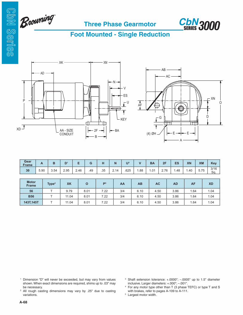
A-68
3000SERIESCbN
CbN
Serie
s
Three Phase Gearmotor
Foot Mounted - Single Reduction
1 Dimension “D” will never be exceeded, but may vary from values
be necessary.2
variations.
3
4 For any motor type other than T (3 phase TEFC) or type T and S with brakes, refer to pages A-109 to A-111.
5 Largest motor width.
XM
ES
V
N
U
KEY
2F
B
P
BA
O
D
E
XN
E
A
(4) ØH
G
AB
AC
XD
AF
AA - SIZECONDUIT
AD
XK
Motor Frame
Type4 XK O P5 AA AB AC AD AF XD
56 T 9.79 8.01 7.22 3/4 6.10 4.50 3.86 1.64 1.04
B56 T 11.04 8.01 7.22 3/4 6.10 4.50 3.86 1.64 1.04
143T,145T T 11.04 8.01 7.22 3/4 6.10 4.50 3.86 1.64 1.04
Gear Frame
A B D1 E G H N U³ V BA 2F ES XN XM Key
30 5.90 3.54 2.95 2.46 .49 .35 2.14 .625 1.88 1.01 2.76 1.48 1.40 5.753/16 Sq.

A-69
3000SERIESCbN
CbN
Serie
sThree Phase Gearmotor
Foot Mounted - Single Reduction
XD KEY
(4) ØHAA - SIZECONDUIT
XN
D
N
V
BA
A
O
E
AB
AC
G
AF
U
ES
E
P
2F
B
XK
AD
XM
1 Dimension “D” will never be exceeded, but may vary from values
be necessary.2
variations.
3
4 For any motor type other than T (3 phase TEFC) or type T and S with brakes, refer to pages A-109 to A-111.
5 Largest motor width.
Motor Frame Type4 XK O P5 AA AB AC AD AF XD
56 T 9.79 8.64 7.22 3/4 6.10 4.21 3.86 .94 1.65
B56 T 11.04 8.64 7.22 3/4 6.10 4.21 3.86 .94 1.65
143T,145T T 11.04 8.64 7.22 3/4 6.10 4.21 3.86 .94 1.65
182T,184T T 14.04 9.76 9.56 3/4 7.52 6.27 5.13 2.13 .64
Gear Frame
A B D1 E G H N U³ V BA 2F ES XN XM Key
31 6.14 4.13 3.15 2.36 .71 .43 1.58 .750 1.50 .71 2.95 1.28 1.83 6.89 3/16 Sq.
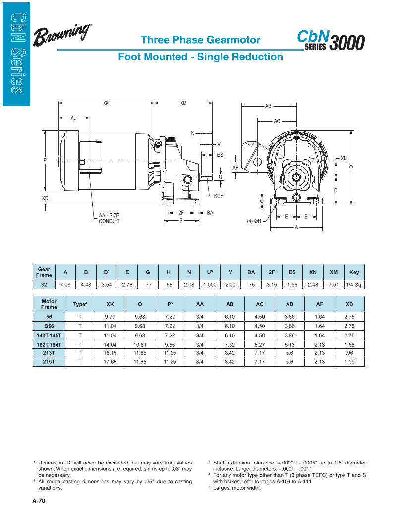
A-70
3000SERIESCbN
CbN
Serie
s
Three Phase Gearmotor
Foot Mounted - Single Reduction
1 Dimension “D” will never be exceeded, but may vary from values
be necessary.2
variations.
3
4 For any motor type other than T (3 phase TEFC) or type T and S with brakes, refer to pages A-109 to A-111.
5 Largest motor width.
XD KEY
(4) ØHAA - SIZECONDUIT
XN
D
N
V
BA
A
O
E
AB
AC
G
AF
U
ES
E
P
2F
B
XK
AD
XM
Motor Frame
Type4 XK O P5 AA AB AC AD AF XD
56 T 9.79 9.68 7.22 3/4 6.10 4.50 3.86 1.64 2.75
B56 T 11.04 9.68 7.22 3/4 6.10 4.50 3.86 1.64 2.75
143T,145T T 11.04 9.68 7.22 3/4 6.10 4.50 3.86 1.64 2.75
182T,184T T 14.04 10.81 9.56 3/4 7.52 6.27 5.13 2.13 1.68
213T T 16.15 11.65 11.25 3/4 8.42 7.17 5.6 2.13 .96
215T T 17.65 11.65 11.25 3/4 8.42 7.17 5.6 2.13 1.09
Gear Frame
A B D1 E G H N U³ V BA 2F ES XN XM Key
32 7.08 4.48 3.54 2.76 .77 .55 2.08 1.000 2.00 .75 3.15 1.56 2.48 7.51 1/4 Sq.
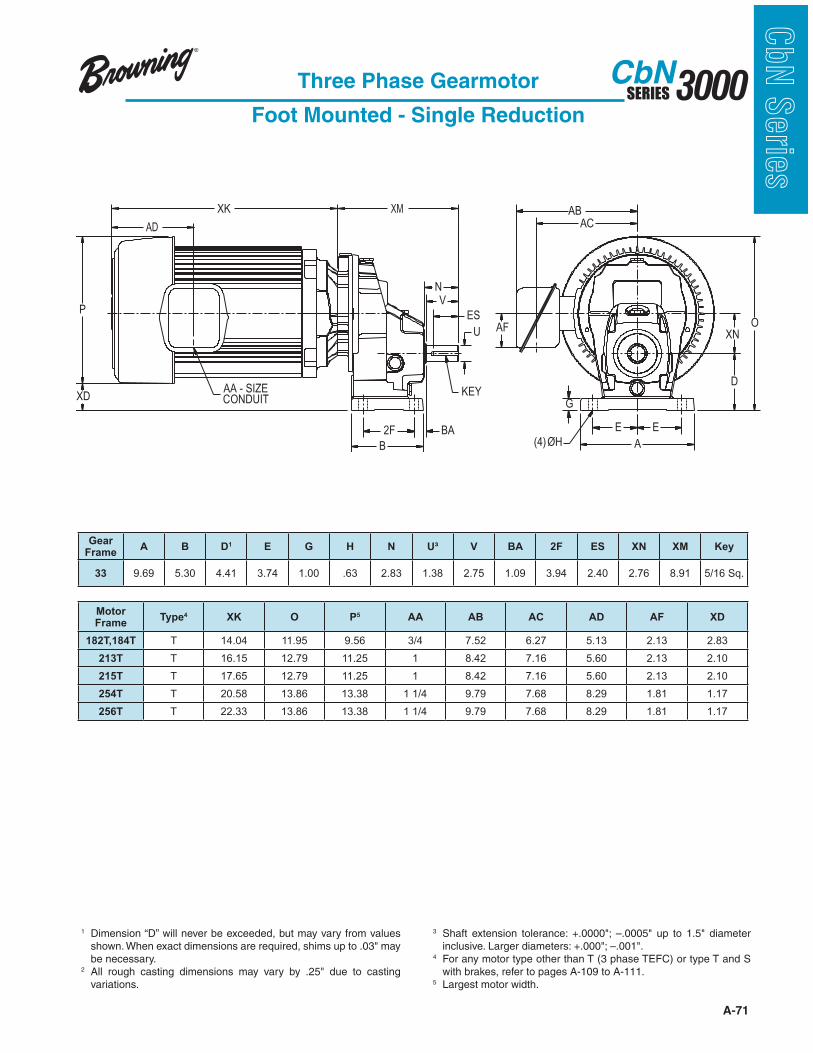
A-71
3000SERIESCbN
CbN
Serie
sThree Phase Gearmotor
Foot Mounted - Single Reduction
1 Dimension “D” will never be exceeded, but may vary from values
be necessary.2
variations.
3
4 For any motor type other than T (3 phase TEFC) or type T and S with brakes, refer to pages A-109 to A-111.
5 Largest motor width.
O
E
A
AF
AB
G
AC
E
XN
D
AD
P
B
BA2F
U
N
ES
V
XD KEY
(4)ØH
AA - SIZECONDUIT
XK XM
Motor Frame
Type4 XK O P5 AA AB AC AD AF XD
182T,184T T 14.04 11.95 9.56 3/4 7.52 6.27 5.13 2.13 2.83
213T T 16.15 12.79 11.25 1 8.42 7.16 5.60 2.13 2.10
215T T 17.65 12.79 11.25 1 8.42 7.16 5.60 2.13 2.10
254T T 20.58 13.86 13.38 1 1/4 9.79 7.68 8.29 1.81 1.17
256T T 22.33 13.86 13.38 1 1/4 9.79 7.68 8.29 1.81 1.17
Gear Frame
A B D1 E G H N U³ V BA 2F ES XN XM Key
33 9.69 5.30 4.41 3.74 1.00 .63 2.83 1.38 2.75 1.09 3.94 2.40 2.76 8.91 5/16 Sq.

A-72
3000SERIESCbN
CbN
Serie
s
Three Phase Gearmotor
Foot Mounted - Single Reduction
O
E
A
AF
AB
G
AC
E
XN
D
AD
P
B
BA2F
U
N
ES
V
XD KEY
(4)ØH
AA - SIZECONDUIT
XK XM
1 Dimension “D” will never be exceeded, but may vary from values
be necessary.2
variations.
3
4 For any motor type other than T (3 phase TEFC) or type T and S with brakes, refer to pages A-109 to A-111.
5 Largest motor width.
Motor Frame
Type4 XK O P5 AA AB AC AD AF XD
182T, 184T T 14.04 13.90 9.56 3/4 7.52 6.27 5.13 2.13 4.28
213T T 16.15 14.25 11.25 1 8.42 7.17 5.6 2.13 3.56
215T T 17.65 14.25 11.25 1 8.42 7.17 5.6 2.13 3.56
254T T 19.61 15.31 13.38 1 1/4 9.79 7.68 8.29 1.81 2.62
256T T 21.36 15.31 13.38 1 1/4 9.79 7.68 8.29 1.81 2.62
284T, 286T T 24.71 15.96 14.66 1 1/2 11.33 9.16 13.19 2.63 1.34
Gear Frame
A B D1 E G H N U³ V BA 2F ES XNXM
Key182T-215T 254T-286T
34 11.02 6.59 5.20 4.25 1.34 .71 3.06 1.50 3.00 1.10 4.92 2.56 3.43 9.98 10.63 3/8 Sq.
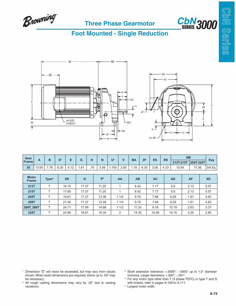
A-73
3000SERIESCbN
CbN
Serie
sThree Phase Gearmotor
Foot Mounted - Single Reduction
D
XNO
EE
A
G
(4) ØH
AF
AC
AB
U
KEY
ES
V
N
2F
BA
B
XD
P
AA-SIZE
CONDUIT
XK XM
AD
1 Dimension “D” will never be exceeded, but may vary from values
be necessary.2
variations.
3
4 For any motor type other than T (3 phase TEFC) or type T and S with brakes, refer to pages A-109 to A-111.
5 Largest motor width.
Motor Frame
Type4 XK O P5 AA AB AC AD AF XD
213T T 16.15 17.37 11.25 1 8.42 7.17 5.6 2.13 5.57
215T T 17.65 17.37 11.25 1 8.42 7.17 5.6 2.13 5.57
254T T 19.61 17.37 13.38 1 1/4 9.79 7.68 8.29 1.81 4.63
256T T 21.36 17.37 13.38 1 1/4 9.79 7.68 8.29 1.81 4.63
284T, 286T T 24.71 17.99 14.66 1 1/2 11.33 9.16 13.19 2.63 3.37
324T T 24.96 18.81 16.34 2 14.30 10.69 14.16 3.25 2.85
Gear Frame
A B D1 E G H N U³ V BA 2F ES XNXM
Key213T-215T 254T-324T
35 13.65 7.76 6.30 5.12 1.61 .79 3.56 1.750 3.50 1.18 6.30 3.06 4.33 10.84 11.36 3/8 Sq.
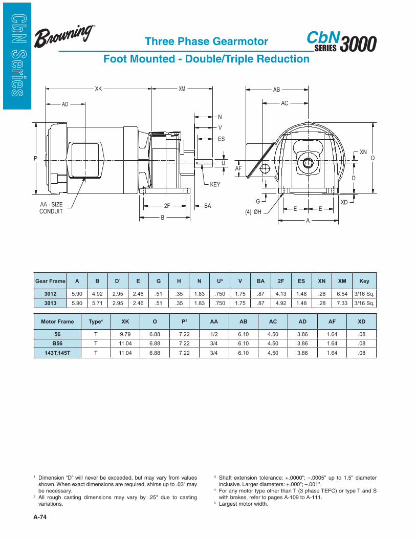
A-74
3000SERIESCbN
CbN
Serie
s
Three Phase Gearmotor
Foot Mounted - Double/Triple Reduction
AA - SIZE
CONDUIT
B
2F BA
KEY
U
N
V
ES
P
A
E(4) ØH
E
G
AF
AC
AB
D
OXN
XD
AD
XMXK
1 Dimension “D” will never be exceeded, but may vary from values
be necessary.2
variations.
3
4 For any motor type other than T (3 phase TEFC) or type T and S with brakes, refer to pages A-109 to A-111.
5 Largest motor width.
Motor Frame Type4 XK O P5 AA AB AC AD AF XD
56 T 9.79 6.88 7.22 1/2 6.10 4.50 3.86 1.64 .08
B56 T 11.04 6.88 7.22 3/4 6.10 4.50 3.86 1.64 .08
143T,145T T 11.04 6.88 7.22 3/4 6.10 4.50 3.86 1.64 .08
Gear Frame A B D1 E G H N U³ V BA 2F ES XN XM Key
3012 5.90 4.92 2.95 2.46 .51 .35 1.83 .750 1.75 .87 4.13 1.48 .28 6.54 3/16 Sq.
3013 5.90 5.71 2.95 2.46 .51 .35 1.83 .750 1.75 .87 4.92 1.48 .28 7.33 3/16 Sq.

A-75
3000SERIESCbN
CbN
Serie
sThree Phase Gearmotor
Foot Mounted - Double/Triple Reduction
1 Dimension “D” will never be exceeded, but may vary from values
be necessary.2
variations.
3
4 For any motor type other than T (3 phase TEFC) or type T and S with brakes, refer to pages A-109 to A-111.
5 Largest motor width.
XMXK
B
2F
BA
O
D
G
A
XD
E E
ABAC
AF
U XN
KEY
AA - SIZECONDUIT (4)ØH
N
V
ES
P
AD
Motor Frame
Type4 XK O P5 AA AB AC AD AF XD
56 T 9.79 6.87 7.22 3/4 6.10 4.21 3.86 .94 .10
B56 T 11.04 6.87 7.22 3/4 6.10 4.21 3.86 .94 .10
143T,145T T 11.04 6.87 7.22 3/4 6.10 4.21 3.86 .94 .10
182T,184T T 14.04 7.99 9.56 3/4 7.52 6.27 5.13 2.13 1.13
Gear Frame
A B D1 E G H XN N U³ V BA 2F ES XM Key
31 6.76 7.68 3.54 2.17 .75 .35 .33 2.08 1.000 2.00 .59 6.50 1.56 9.46 1/4 Sq.
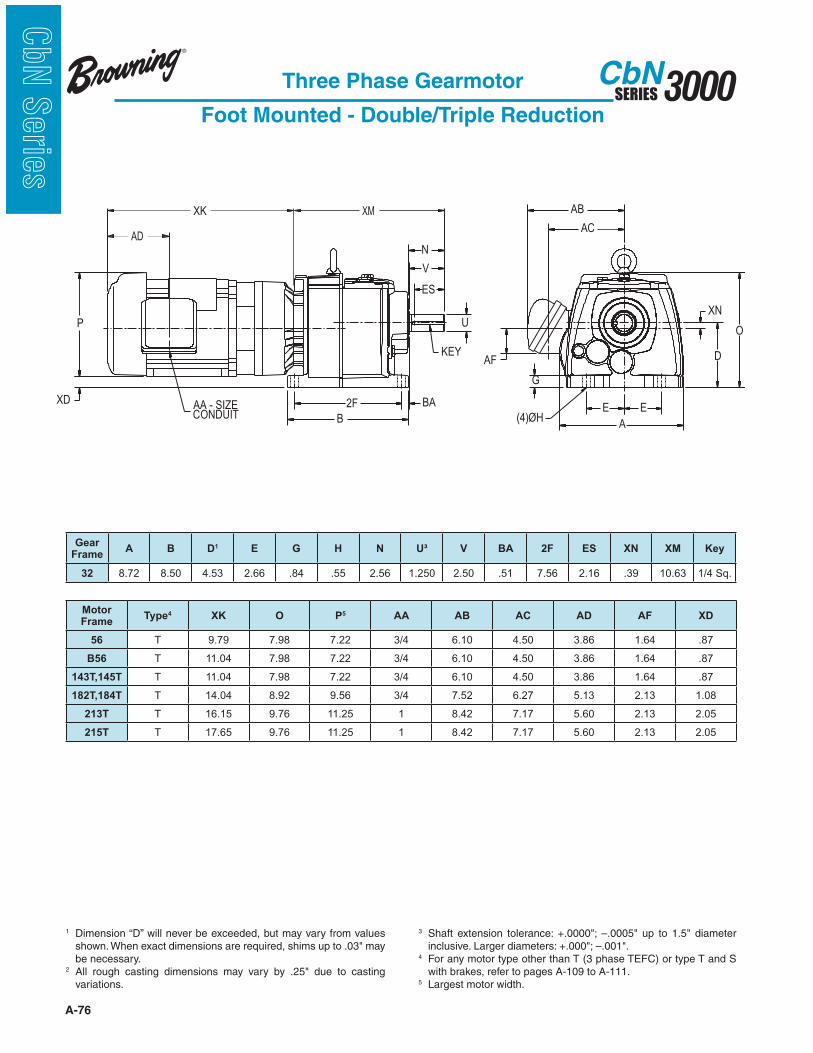
A-76
3000SERIESCbN
CbN
Serie
s
Three Phase Gearmotor
Foot Mounted - Double/Triple Reduction
1 Dimension “D” will never be exceeded, but may vary from values
be necessary.2
variations.
3
4 For any motor type other than T (3 phase TEFC) or type T and S with brakes, refer to pages A-109 to A-111.
5 Largest motor width.
B
2F BA
KEY
U
N
V
ES
P
A
E(4)ØH
E
G
AF
AC
AB
D
O
XN
XD AA - SIZECONDUIT
XMXK
AD
Motor Frame
Type4 XK O P5 AA AB AC AD AF XD
56 T 9.79 7.98 7.22 3/4 6.10 4.50 3.86 1.64 .87
B56 T 11.04 7.98 7.22 3/4 6.10 4.50 3.86 1.64 .87
143T,145T T 11.04 7.98 7.22 3/4 6.10 4.50 3.86 1.64 .87
182T,184T T 14.04 8.92 9.56 3/4 7.52 6.27 5.13 2.13 1.08
213T T 16.15 9.76 11.25 1 8.42 7.17 5.60 2.13 2.05
215T T 17.65 9.76 11.25 1 8.42 7.17 5.60 2.13 2.05
Gear Frame
A B D1 E G H N U³ V BA 2F ES XN XM Key
32 8.72 8.50 4.53 2.66 .84 .55 2.56 1.250 2.50 .51 7.56 2.16 .39 10.63 1/4 Sq.
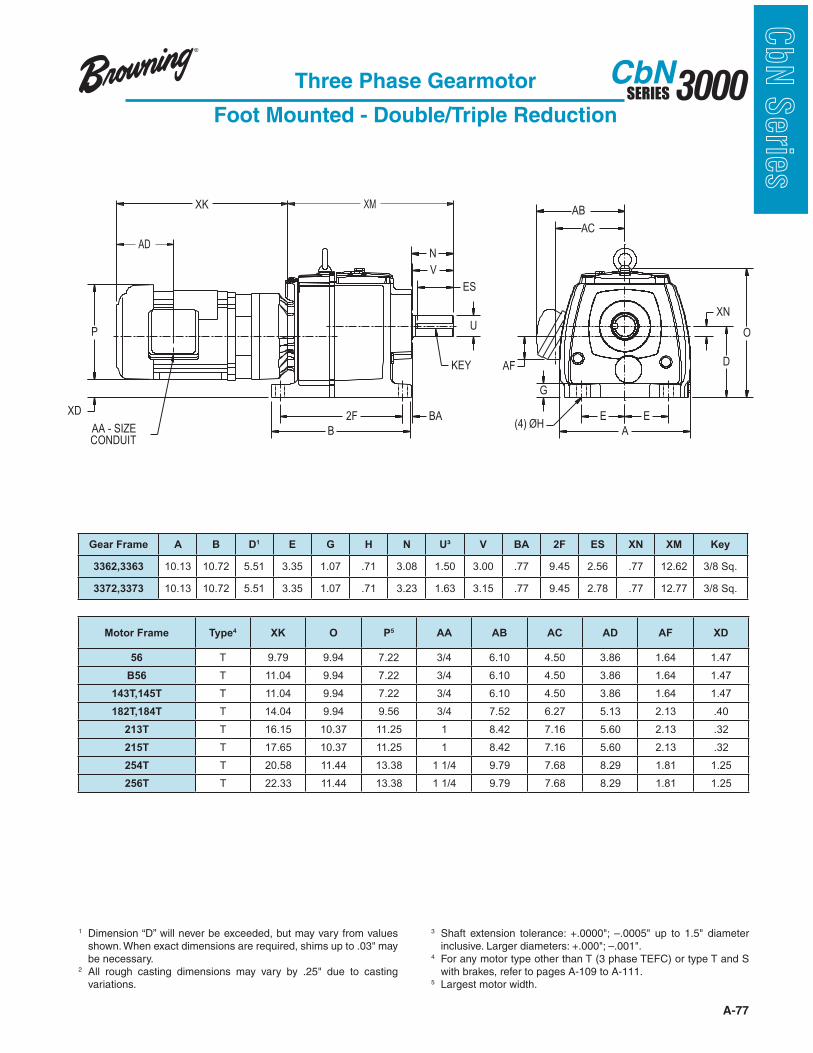
A-77
3000SERIESCbN
CbN
Serie
sThree Phase Gearmotor
Foot Mounted - Double/Triple Reduction
1 Dimension “D” will never be exceeded, but may vary from values
be necessary.2
variations.
3
4 For any motor type other than T (3 phase TEFC) or type T and S with brakes, refer to pages A-109 to A-111.
5 Largest motor width.
AD
XK
A
E E
G
O
D
XN
AB
AC
AF
XD
KEY
(4) ØHAA - SIZECONDUIT
B
2F BA
U
N
V
ES
P
XM
Motor Frame Type4 XK O P5 AA AB AC AD AF XD
56 T 9.79 9.94 7.22 3/4 6.10 4.50 3.86 1.64 1.47
B56 T 11.04 9.94 7.22 3/4 6.10 4.50 3.86 1.64 1.47
143T,145T T 11.04 9.94 7.22 3/4 6.10 4.50 3.86 1.64 1.47
182T,184T T 14.04 9.94 9.56 3/4 7.52 6.27 5.13 2.13 .40
213T T 16.15 10.37 11.25 1 8.42 7.16 5.60 2.13 .32
215T T 17.65 10.37 11.25 1 8.42 7.16 5.60 2.13 .32
254T T 20.58 11.44 13.38 1 1/4 9.79 7.68 8.29 1.81 1.25
256T T 22.33 11.44 13.38 1 1/4 9.79 7.68 8.29 1.81 1.25
Gear Frame A B D1 E G H N U³ V BA 2F ES XN XM Key
3362,3363 10.13 10.72 5.51 3.35 1.07 .71 3.08 1.50 3.00 .77 9.45 2.56 .77 12.62 3/8 Sq.
3372,3373 10.13 10.72 5.51 3.35 1.07 .71 3.23 1.63 3.15 .77 9.45 2.78 .77 12.77 3/8 Sq.
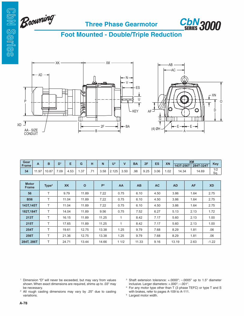
A-78
3000SERIESCbN
CbN
Serie
s
Three Phase Gearmotor
Foot Mounted - Double/Triple Reduction
1 Dimension “D” will never be exceeded, but may vary from values
be necessary.2
variations.
3
4 For any motor type other than T (3 phase TEFC) or type T and S with brakes, refer to pages A-109 to A-111.
5 Largest motor width.
AD
XK
A
E E
G
O
D
XN
AB
AC
AF
XD
KEY
(4) ØHAA - SIZECONDUIT
B
2F BA
U
N
V
ES
P
XM
Motor Frame
Type4 XK O P5 AA AB AC AD AF XD
56 T 9.79 11.89 7.22 0.75 6.10 4.50 3.86 1.64 2.75
B56 T 11.04 11.89 7.22 0.75 6.10 4.50 3.86 1.64 2.75
143T,145T T 11.04 11.89 7.22 0.75 6.10 4.50 3.86 1.64 2.75
182T,184T T 14.04 11.89 9.56 0.75 7.52 6.27 5.13 2.13 1.72
213T T 16.15 11.89 11.25 1 8.42 7.17 5.60 2.13 1.00
215T T 17.65 11.89 11.25 1 8.42 7.17 5.60 2.13 1.00
254T T 19.61 12.75 13.38 1.25 9.79 7.68 8.29 1.81 .06
256T T 21.36 12.75 13.38 1.25 9.79 7.68 8.29 1.81 .06
284T, 286T T 24.71 13.44 14.66 1 1/2 11.33 9.16 13.19 2.63 -1.22
Gear Frame
A B D1 E G H N U³ V BA 2F ES XNXM
Key143T-256T 284T-324T
34 11.97 10.87 7.09 4.53 1.37 .71 3.58 2.125 3.50 .98 9.25 3.06 1.02 14.34 14.691/2 Sq.

A-79
3000SERIESCbN
CbN
Serie
sThree Phase Gearmotor
Foot Mounted - Double/Triple Reduction
1 Dimension “D” will never be exceeded, but may vary from values
be necessary.2
variations.
3
4 For any motor type other than T (3 phase TEFC) or type T and S with brakes, refer to pages A-109 to A-111.
5 Largest motor width.
AD
XK
A
E E
G
O
D
XN
AB
AC
AF
XD
KEY
(4) ØHAA - SIZECONDUIT
B
2F BA
U
N
V
ES
P
XM
Motor Frame
Type4 XK O P5 AA AB AC AD AF XD
B56 T 11.04 14.84 7.22 3/4 6.10 4.50 3.86 1.64 4.40
143T,145T T 11.04 14.84 7.22 3/4 6.10 4.50 3.86 1.64 4.40
182T,184T T 14.04 14.84 9.56 3/4 7.52 6.27 5.13 2.13 3.38
213T T 16.15 14.84 11.25 1 8.42 7.17 5.60 2.13 2.65
215T T 17.65 14.84 11.25 1 8.42 7.17 5.60 2.13 2.65
254T T 19.61 14.84 13.38 1 1/4 9.79 7.68 8.29 1.81 1.72
256T T 21.36 14.84 13.38 1 1/4 9.79 7.68 8.29 1.81 1.72
284T, 286T T 24.71 15.01 14.66 1 1/2 11.33 9.16 13.19 2.63 .39
Gear Frame
A B D1 E G H N U³ V BA 2F ES XNXM
Key143T-256T 284T-324T
35 14.19 12.89 8.86 5.51 1.73 .87 4.81 2.38 4.72 1.10 11.02 4.19 1.14 16.60 17.12 5/8 Sq.
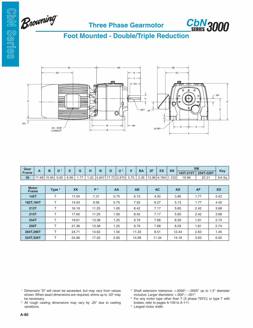
A-80
3000SERIESCbN
CbN
Serie
s
Three Phase Gearmotor
Foot Mounted - Double/Triple Reduction
1 Dimension “D” will never be exceeded, but may vary from values
be necessary.2
variations.
3
4 For any motor type other than T (3 phase TEFC) or type T with brakes, refer to pages A-109 to A-111.
5 Largest motor width.
B
XN
2F BA
N
V
ES
U
KEY
XM
P
XD
AA - SIZE
CONDUIT
AD
XK
D
O
E E
A
G
(4) ØH
AF
AB
AC
CbN36-37 Double/Triple Reduction - Foot Mounted Gearmotor
Gear Frame
A B D 1 E G H N O U 3 V BA 2F ES XNXM
Key145T-215T 254T-326T
36 17.68 15.95 9.85 6.99 1.77 1.02 5.847 17.72 2.875 5.75 2.36 13.98 4.784 1.102 19.96 20.31 3/4 Sq
MotorFrame
Type 4 XK P 5 AA AB AC AD AF XD
145T T 11.04 7.31 0.75 6.10 4.50 3.86 1.77 5.42
182T,184T T 14.04 9.56 0.75 7.52 6.27 5.13 1.77 4.40
213T T 16.16 11.25 1.00 8.42 7.17 5.60 2.42 3.68
215T T 17.65 11.25 1.00 8.42 7.17 5.60 2.42 3.68
254T T 19.61 13.38 1.25 9.79 7.68 8.29 1.81 2.74
256T T 21.36 13.38 1.25 9.79 7.68 8.29 1.81 2.74
284T,286T T 24.71 14.62 1.50 11.33 8.51 12.44 2.63 1.45
324T,326T T 24.96 17.20 2.00 14.99 11.34 14.16 3.63 0.55

A-81
3000SERIESCbN
CbN
Serie
sThree Phase Gearmotor
Foot Mounted - Double/Triple Reduction
1 Dimension “D” will never be exceeded, but may vary from values
be necessary.2
variations.
3
4 For any motor type other than T (3 phase TEFC) or type T with brakes, refer to pages A-109 to A-111.
5 Largest motor width.
B
XN
2F BA
N
V
ES
U
KEY
XM
P
XD
AA - SIZE
CONDUIT
AD
XK
D
O
E E
A
G
(4) ØH
AF
AB
AC
Gear Frame
A B D 1 E G H N O U 3 V BA 2F ES XNXM
Key182T-215T 254T-326T
37 20.39 17.91 12.40 8.27 2.17 1.02 7.127 20.40 3.625 7.00 2.56 15.35 5.893 2.362 23.88 24.23 7/8 Sq
MotorFrame
Type 4 XK P 5 AA AB AC AD AF XD
182T,184T T 14.04 9.56 0.75 7.52 6.27 5.13 1.77 5.69
213T T 16.16 11.25 1.00 8.42 7.17 $5.60 2.42 4.97
215T T 17.65 11.25 1.00 8.42 7.17 $5.60 2.42 4.97
254T T 19.61 13.38 1.25 9.79 7.68 8.29 1.81 4.03
256T T 21.36 13.38 1.25 9.79 7.68 8.29 1.81 4.03
284T,286T T 24.71 14.62 1.50 11.33 8.51 12.44 2.63 2.75
324T,326T T 24.96 17.20 2.00 14.99 11.34 14.16 3.63 1.84

A-82
3000SERIESCbN
CbN
Serie
s
Three Phase Gearmotor
Foot Mounted - Double/Triple Reduction
1 Dimension “D” will never be exceeded, but may vary from values
be necessary.2
variations.
3 4 For any motor type other than T (3 phase TEFC) or type T and S
with brakes, refer to pages A-109 to A-111.5 Largest motor width.
FrameMotor Type4 XK O P5 AA AB AC AD AF XD
213T T 17.47 23.47 11.25 1 8.25 6.39 5.6 1.56 6.35
215T T 18.96 23.47 11.25 1 8.25 6.39 5.6 1.56 6.35
254T T 19.61 23.47 13.38 1 1/4 9.96 7.72 8.29 1.81 5.41
256T T 21.36 23.47 13.38 1 1/4 9.96 7.72 8.29 1.81 5.41
284T,286T T 24.71 23.47 14.66 1 1/2 11.33 9.16 13.19 2.63 4.01
324T,326T T 24.96 27.60 17.20 2 14.99 11.34 14.16 3.63 3.11
Gear Frame
A B D1 E G H N O U³ V BA 2F ES XN XM Key
38 23.94 21.65 13.98 10.04 2.35 1.02 9.99 22.60 4.375 9.99 1.97 18.90 9.02 2.559 29.98 1 SQ
B
XN
2F BA
N
V
ES
U
KEY
XM
P
XD
AA - SIZE
CONDUIT
AD
XK
D
O
E E
A
G
(4) ØH
AF
AB
AC

A-83
3000SERIESCbN
CbN
Serie
sThree Phase Gearmotor
Foot Mounted - Combined Reduction
XK
AD
XD
KEY
(4) ØHAA - SIZECONDUIT
P
N
V
ES
U
BA
B
2F E
A
E
O
XN
D
AB
AC
AF
G
XM
1 Dimension “D” will never be exceeded, but may vary from values
be necessary.2
variations.
3
4 For any motor type other than T (3 phase TEFC) or type T and S with brakes, refer to pages A-109 to A-111.
5 Largest motor width.
FrameMotor Type4 XK
OP5 AA AB AC AD AF
XD
32 33 34 32 33 34
56 T 9.79 8.07 9.94 11.89 7.22 3/4 6.10 4.50 3.86 1.64 1.1 1.71 2.42
B56 T 11.04 8.07 9.94 11.89 7.22 3/4 6.10 4.50 3.86 1.64 1.1 1.71 2.42
143T,145T T 11.04 8.07 9.94 11.89 7.22 3/4 6.10 4.50 3.86 1.64 1.1 1.71 2.42
Gear Frame
A B D1 E G H N U³ V BA 2F ES XN XM Key
32 8.72 8.50 4.53 2.66 .84 .55 2.56 1.250 2.50 .51 7.56 2.16 .12 14.71 1/4 Sq.
33 10.13 10.72 5.51 3.35 1.07 .71 3.23 1.625 3.15 .77 9.45 2.78 .49 16.86 3/8 Sq.
34 11.97 10.87 7.09 4.53 1.37 .71 3.58 2.125 3.50 .98 9.25 3.06 1.35 21.31 1/2 Sq.
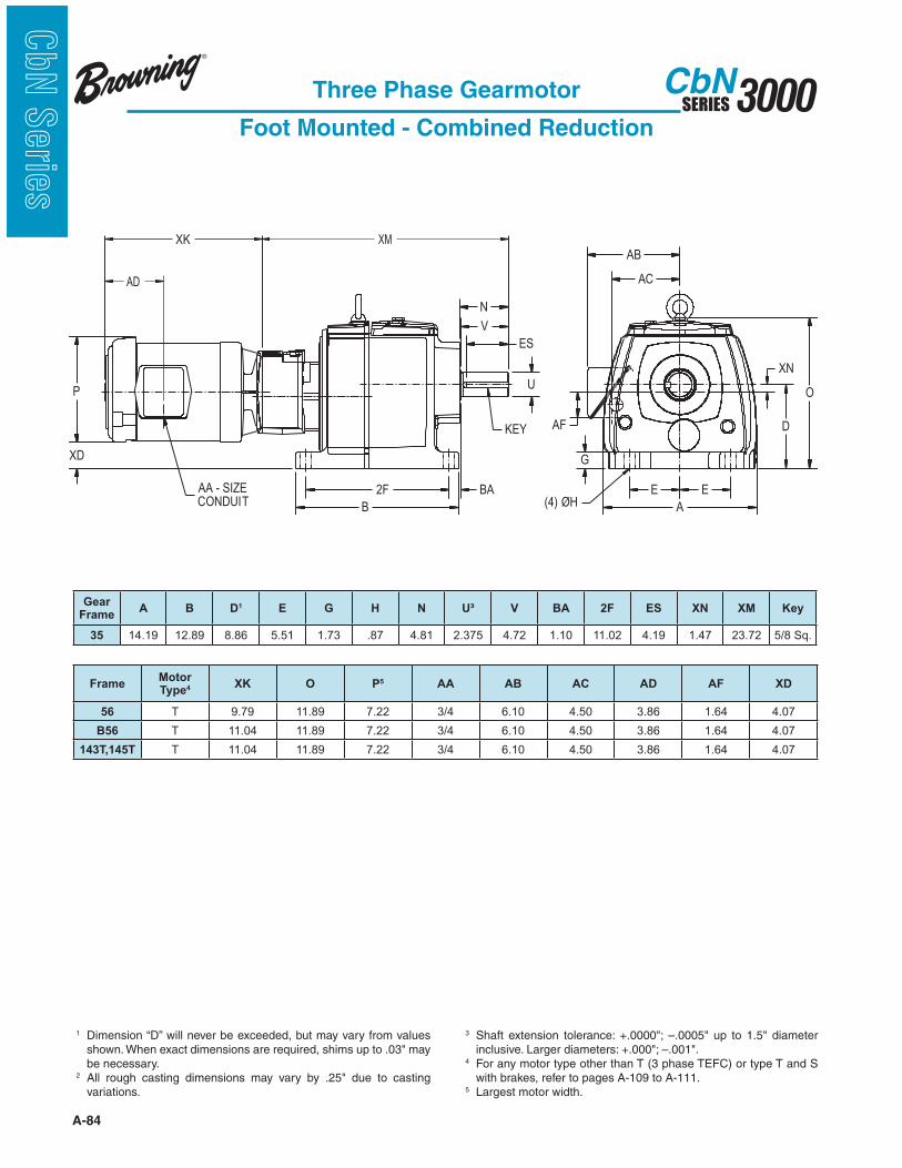
A-84
3000SERIESCbN
CbN
Serie
s
Three Phase Gearmotor
Foot Mounted - Combined Reduction
XK
AD
XD
KEY
(4) ØHAA - SIZECONDUIT
P
N
V
ES
U
BA
B
2F E
A
E
O
XN
D
AB
AC
AF
G
XM
1 Dimension “D” will never be exceeded, but may vary from values
be necessary.2
variations.
3
4 For any motor type other than T (3 phase TEFC) or type T and S with brakes, refer to pages A-109 to A-111.
5 Largest motor width.
FrameMotor Type4 XK O P5 AA AB AC AD AF XD
56 T 9.79 11.89 7.22 3/4 6.10 4.50 3.86 1.64 4.07
B56 T 11.04 11.89 7.22 3/4 6.10 4.50 3.86 1.64 4.07
143T,145T T 11.04 11.89 7.22 3/4 6.10 4.50 3.86 1.64 4.07
Gear Frame
A B D1 E G H N U³ V BA 2F ES XN XM Key
35 14.19 12.89 8.86 5.51 1.73 .87 4.81 2.375 4.72 1.10 11.02 4.19 1.47 23.72 5/8 Sq.

A-85
3000SERIESCbN
CbN
Serie
sThree Phase Gearmotor
Foot Mounted - Combined Reduction
1 Dimension “D” will never be exceeded, but may vary from values
be necessary.2
variations.
3
4 For any motor type other than T (3 phase TEFC) or type T with brakes, refer to pages A-109 to A-111.
5 Largest motor width.
B
E E
A
G
(4) ØH
XN
D
O
AF
AB
AC
2F BA
N
V
ES
U
KEY
XM
AA - SIZE
CONDUIT
p
XD
XK
AD
Gear Frame
A B D1 E G H N O U³ V BA 2F ES XN XM Key
36 17.68 15.95 9.85 6.99 1.77 1.02 5.847 17.72 2.875 5.75 2.36 13.98 4.784 1.492 27.62 3/4 Sq
37 20.39 17.91 12.40 8.27 2.17 1.02 7.127 20.40 3.625 7.00 2.56 15.35 5.893 2.752 31.54 7/8 Sq
Motor Frame
Gear Frame
Type 4 XK P 5 AA AB AC AD AFXD
36 37
56 All T 9.79 7.22 0.75 6.10 4.50 3.86 1.77 5.03 6.33
B56 All T 11.04 7.22 0.75 6.10 4.50 3.86 1.77 5.03 6.33
143T, 145T All T 11.04 7.22 0.75 6.10 4.50 3.86 1.77 5.03 6.33
182T,184T All T 14.04 9.56 0.75 7.52 6.27 5.13 1.77 4.01 5.30
213T 37 T 16.16 11.25 1.00 8.42 7.17 5.60 2.42 - 4.58
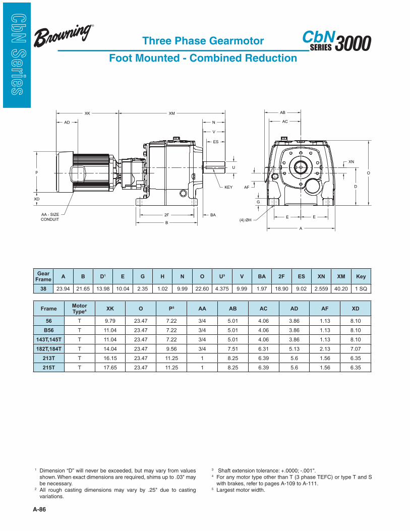
A-86
3000SERIESCbN
CbN
Serie
s
B
E E
A
G
(4) ØH
XN
D
O
AF
AB
AC
2F BA
N
V
ES
U
KEY
XM
AA - SIZE
CONDUIT
p
XD
XK
AD
Three Phase Gearmotor
Foot Mounted - Combined Reduction
1 Dimension “D” will never be exceeded, but may vary from values
be necessary.2
variations.
3 4 For any motor type other than T (3 phase TEFC) or type T and S
with brakes, refer to pages A-109 to A-111.5 Largest motor width.
FrameMotor Type4 XK O P5 AA AB AC AD AF XD
56 T 9.79 23.47 7.22 3/4 5.01 4.06 3.86 1.13 8.10
B56 T 11.04 23.47 7.22 3/4 5.01 4.06 3.86 1.13 8.10
143T,145T T 11.04 23.47 7.22 3/4 5.01 4.06 3.86 1.13 8.10
182T,184T T 14.04 23.47 9.56 3/4 7.51 6.31 5.13 2.13 7.07
213T T 16.15 23.47 11.25 1 8.25 6.39 5.6 1.56 6.35
215T T 17.65 23.47 11.25 1 8.25 6.39 5.6 1.56 6.35
Gear Frame
A B D1 E G H N O U³ V BA 2F ES XN XM Key
38 23.94 21.65 13.98 10.04 2.35 1.02 9.99 22.60 4.375 9.99 1.97 18.90 9.02 2.559 40.20 1 SQ

A-87
3000SERIESCbN
CbN
Serie
sThree Phase Gearmotor
Flange Mounted - Single Reduction
P ES
AH
BB
BE
ØA K
ØBDU
KEY
AB
AC
XN
(4) ØBF
ØAJ
AF
O
AA - SIZECONDUIT
AD
XK XM
2 variations.
3
4 For any motor type other than T (3 phase TEFC) or type T and S with brakes, refer to pages A-109 to A-111. Standard as shown with conduit opening down.
5 Largest motor width.
Motor Frame Type4 XK O P5 AA AB AC AD AF
56 T 9.79 5.05 7.22 3/4 6.10 4.50 3.86 1.64
B56 T 11.04 5.05 7.22 3/4 6.10 4.50 3.86 1.64
143T,145T T 11.04 5.05 7.22 3/4 6.10 4.50 3.86 1.64
Gear Frame U³ AH ES XN XM Key
30 .625 2.06 1.48 1.40 5.75 3/16 Sq.
Flange Type AK AJ BB BD BE BF
56C 4.50 5.875 .12 6.50 .39 3/8-16
BS 3.74 4.53 .12 5.51 .31 .35
BD1 3.15 3.94 .12 4.72 39 .28
BD2 4.33 5.12 .08 6.30 39 .35
BD3 5.12 6.50 .12 7.87 .31 .35

A-88
3000SERIESCbN
CbN
Serie
s
Three Phase Gearmotor
Flange Mounted - Single Reduction
XK
P
ES
AH
BB
BE
ØAK
ØBDU
KEY
AB
AC
XN
(4)ØBF
ØAJ
AF
O
XD
AA - SIZECONDUIT
XM
AD
2 variations.
3
4 For any motor type other than T (3 phase TEFC) or type T and S with brakes, refer to pages A-109 to A-111.
5 Largest motor width.
Motor Frame
Type4 XK O P5 AA AB AC AD AF
56 T 9.79 5.49 7.22 3/4 6.10 4.21 3.86 .83
B56 T 11.04 5.49 7.22 3/4 6.10 4.21 3.86 .83
143T,145T T 11.04 5.49 7.22 3/4 6.10 4.21 3.86 .83
182T,184T T 14.04 6.61 9.56 3/4 7.52 6.27 5.13 2.13
Gear Frame U³ AH ES XD XN XM Key
31 .75 1.50 1.28 3.15 1.83 7.20 3/16 Sq.
Flange Type AK AJ BB BD BE BF
BS 4.33 5.12 .14 6.29 .39 .35
BD2 3.74 4.53 .14 5.50 .39 .35
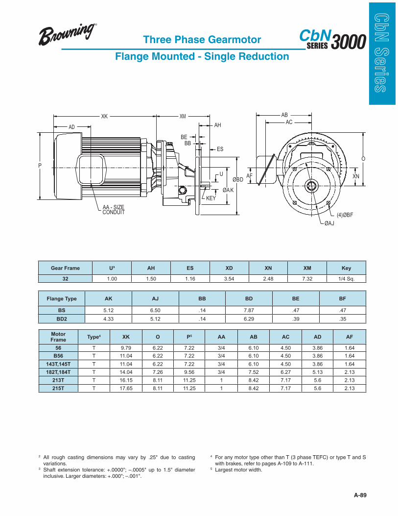
A-89
3000SERIESCbN
CbN
Serie
sThree Phase Gearmotor
Flange Mounted - Single Reduction
XK
AD
P
ES
AH
BB
BE
ØAK
ØBDU
KEY
AB
AC
XN
(4)ØBF
ØAJ
AF
O
AA - SIZECONDUIT
XM
2 variations.
3
4 For any motor type other than T (3 phase TEFC) or type T and S with brakes, refer to pages A-109 to A-111.
5 Largest motor width.
Motor Frame
Type4 XK O P5 AA AB AC AD AF
56 T 9.79 6.22 7.22 3/4 6.10 4.50 3.86 1.64
B56 T 11.04 6.22 7.22 3/4 6.10 4.50 3.86 1.64
143T,145T T 11.04 6.22 7.22 3/4 6.10 4.50 3.86 1.64
182T,184T T 14.04 7.26 9.56 3/4 7.52 6.27 5.13 2.13
213T T 16.15 8.11 11.25 1 8.42 7.17 5.6 2.13
215T T 17.65 8.11 11.25 1 8.42 7.17 5.6 2.13
Gear Frame U³ AH ES XD XN XM Key
32 1.00 1.50 1.16 3.54 2.48 7.32 1/4 Sq.
Flange Type AK AJ BB BD BE BF
BS 5.12 6.50 .14 7.87 .47 .47
BD2 4.33 5.12 .14 6.29 .39 .35
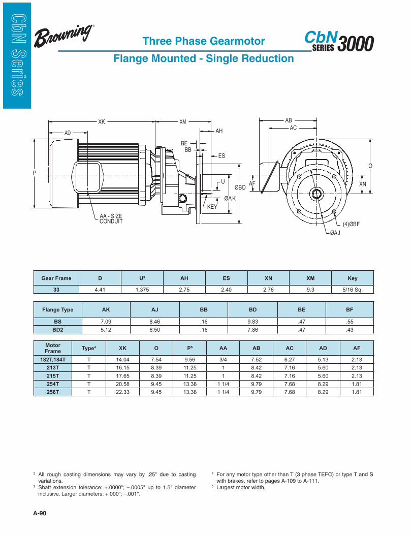
A-90
3000SERIESCbN
CbN
Serie
s
Three Phase Gearmotor
Flange Mounted - Single Reduction
2 variations.
3
4 For any motor type other than T (3 phase TEFC) or type T and S with brakes, refer to pages A-109 to A-111.
5 Largest motor width.
XK
AD
P
ES
AH
BB
BE
ØAK
ØBDU
KEY
AB
AC
XN
(4)ØBF
ØAJ
AF
O
AA - SIZECONDUIT
XM
Motor Frame
Type4 XK O P5 AA AB AC AD AF
182T,184T T 14.04 7.54 9.56 3/4 7.52 6.27 5.13 2.13
213T T 16.15 8.39 11.25 1 8.42 7.16 5.60 2.13
215T T 17.65 8.39 11.25 1 8.42 7.16 5.60 2.13
254T T 20.58 9.45 13.38 1 1/4 9.79 7.68 8.29 1.81
256T T 22.33 9.45 13.38 1 1/4 9.79 7.68 8.29 1.81
Gear Frame D U³ AH ES XN XM Key
33 4.41 1.375 2.75 2.40 2.76 9.3 5/16 Sq.
Flange Type AK AJ BB BD BE BF
BS 7.09 8.46 .16 9.83 .47 .55
BD2 5.12 6.50 .16 7.86 .47 .43

A-91
3000SERIESCbN
CbN
Serie
sThree Phase Gearmotor
Flange Mounted - Single Reduction
XK
AD
P
ES
AH
BB
BE
ØAK
ØBDU
KEY
AB
AC
XN
(4)ØBF
ØAJ
AF
O
AA - SIZECONDUIT
XM
2 variations.
3
4 For any motor type other than T (3 phase TEFC) or type T and S with brakes, refer to pages A-109 to A-111.
5 Largest motor width.
Motor Frame
Type4 XK O P5 AA AB AC AD AF XD
182T,184T T 14.04 8.70 9.56 3/4 7.52 6.27 5.13 2.13 4.28
213T T 16.15 9.05 11.25 1 8.42 7.17 5.60 2.13 3.56
215T T 17.65 9.05 11.25 1 8.42 7.17 5.60 2.13 2.62
254T T 19.61 10.12 13.38 1 1/4 9.79 7.68 8.29 1.81 2.62
256T T 21.36 10.12 13.38 1 1/4 9.79 7.68 8.29 1.81 2.62
284T T 21.86 10.12 13.38 1 1/2 10.71 8.18 8.29 2.13 2.62
286T T 23.36 10.12 13.38 1 1/2 10.71 8.18 8.29 2.13 2.62
Gear Frame XD U³ AH ES XNXM
Key182T-215T 254T-324T
34 5.20 1.50 3.00 2.56 3.43 11.05 11.4 3/8 Sq.
Flange Type AK AJ BB BD BE BF
BS 9.06 10.43 .16 11.80 59 .55
BD2 7.09 8.46 .16 9.84 59 .55
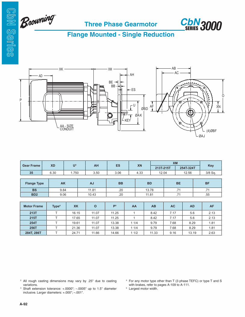
A-92
3000SERIESCbN
CbN
Serie
s
XK
AD
P
ES
AH
BB
BE
ØAK
ØBDU
KEY
AB
AC
XN
(4)ØBF
ØAJ
AF
O
AA - SIZECONDUIT
XM
Three Phase Gearmotor
Flange Mounted - Single Reduction
2 variations.
3
4 For any motor type other than T (3 phase TEFC) or type T and S with brakes, refer to pages A-109 to A-111.
5 Largest motor width.
Motor Frame Type4 XK O P5 AA AB AC AD AF
213T T 16.15 11.07 11.25 1 8.42 7.17 5.6 2.13
215T T 17.65 11.07 11.25 1 8.42 7.17 5.6 2.13
254T T 19.61 11.07 13.38 1 1/4 9.79 7.68 8.29 1.81
256T T 21.36 11.07 13.38 1 1/4 9.79 7.68 8.29 1.81
284T, 286T T 24.71 11.66 14.66 1 1/2 11.33 9.16 13.19 2.63
Gear Frame XD U³ AH ES XNXM
Key213T-215T 254T-324T
35 6.30 1.750 3.50 3.06 4.33 12.04 12.56 3/8 Sq.
Flange Type AK AJ BB BD BE BF
BS 9.84 11.81 .20 13.78 .71 .71
BD2 9.06 10.43 .20 11.81 .71 .55
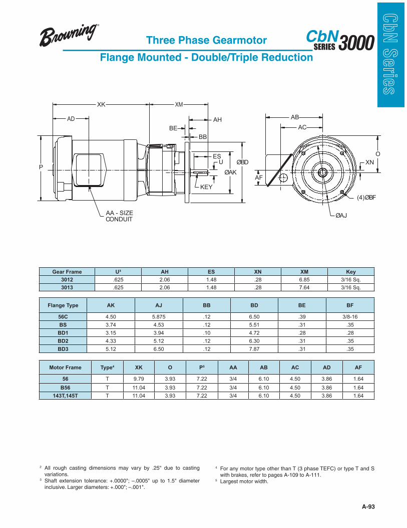
A-93
3000SERIESCbN
CbN
Serie
sThree Phase Gearmotor
Flange Mounted - Double/Triple Reduction
ESU
ØAK
KEY
BB
BE
AH
PØBD
ØAJ
(4)ØBF
XN
AC
AB
O
AF
AA - SIZECONDUIT
XK XM
AD
2 variations.
3
4 For any motor type other than T (3 phase TEFC) or type T and S with brakes, refer to pages A-109 to A-111.
5 Largest motor width.
Motor Frame Type4 XK O P5 AA AB AC AD AF
56 T 9.79 3.93 7.22 3/4 6.10 4.50 3.86 1.64
B56 T 11.04 3.93 7.22 3/4 6.10 4.50 3.86 1.64
143T,145T T 11.04 3.93 7.22 3/4 6.10 4.50 3.86 1.64
Gear Frame U³ AH ES XN XM Key
3012 .625 2.06 1.48 .28 6.85 3/16 Sq.
3013 .625 2.06 1.48 .28 7.64 3/16 Sq.
Flange Type AK AJ BB BD BE BF
56C 4.50 5.875 .12 6.50 .39 3/8-16
BS 3.74 4.53 .12 5.51 .31 .35
BD1 3.15 3.94 .10 4.72 .28 .28
BD2 4.33 5.12 .12 6.30 .31 .35
BD3 5.12 6.50 .12 7.87 .31 .35
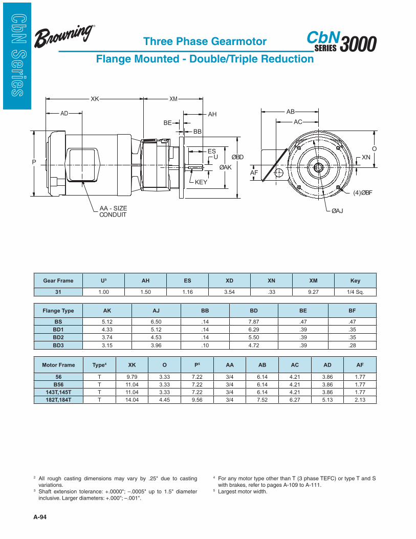
A-94
3000SERIESCbN
CbN
Serie
s
Three Phase Gearmotor
Flange Mounted - Double/Triple Reduction
ESU
ØAK
KEY
BB
BE
AH
PØBD
ØAJ
(4)ØBF
XN
AC
AB
O
AF
AA - SIZECONDUIT
XK XM
AD
2 variations.
3
4 For any motor type other than T (3 phase TEFC) or type T and S with brakes, refer to pages A-109 to A-111.
5 Largest motor width.
Motor Frame Type4 XK O P5 AA AB AC AD AF
56 T 9.79 3.33 7.22 3/4 6.14 4.21 3.86 1.77
B56 T 11.04 3.33 7.22 3/4 6.14 4.21 3.86 1.77
143T,145T T 11.04 3.33 7.22 3/4 6.14 4.21 3.86 1.77
182T,184T T 14.04 4.45 9.56 3/4 7.52 6.27 5.13 2.13
Gear Frame U³ AH ES XD XN XM Key
31 1.00 1.50 1.16 3.54 .33 9.27 1/4 Sq.
Flange Type AK AJ BB BD BE BF
BS 5.12 6.50 .14 7.87 .47 .47
BD1 4.33 5.12 .14 6.29 .39 .35
BD2 3.74 4.53 .14 5.50 .39 .35
BD3 3.15 3.96 .10 4.72 .39 .28
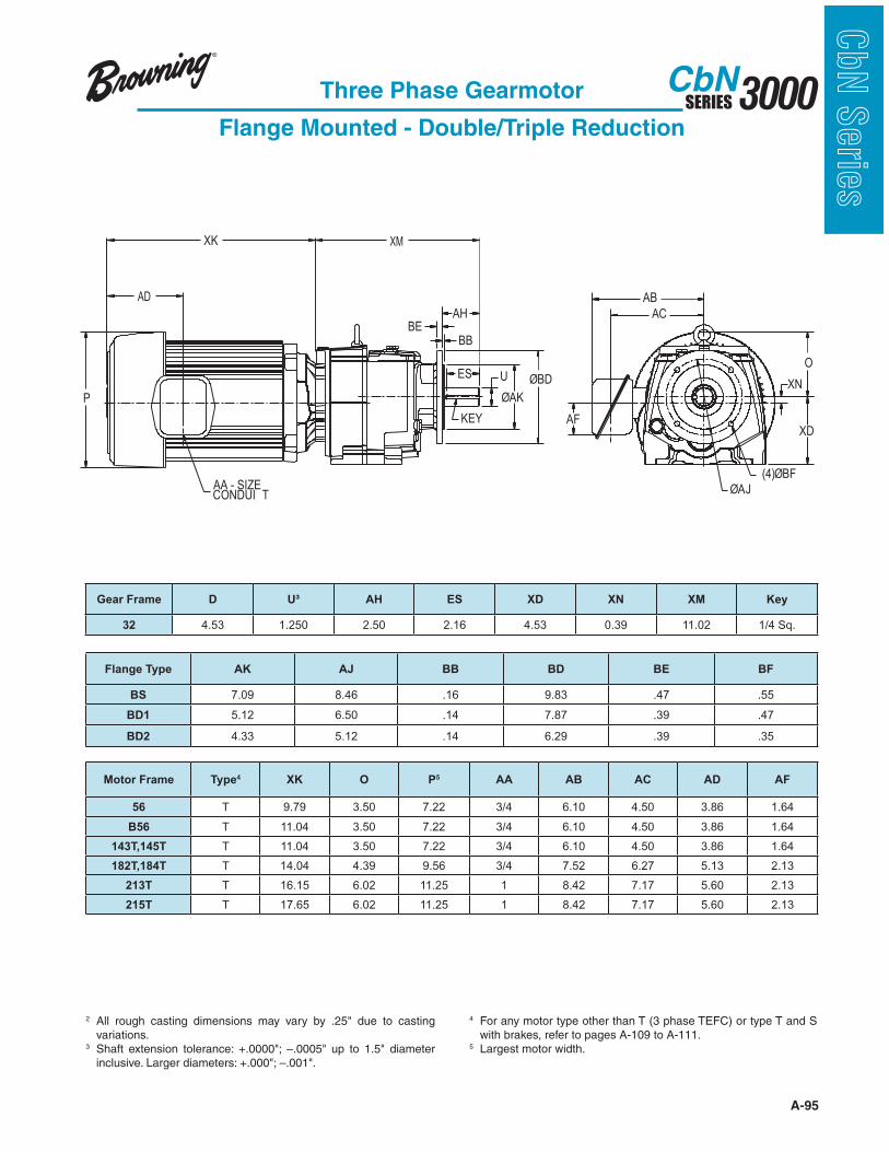
A-95
3000SERIESCbN
CbN
Serie
sThree Phase Gearmotor
Flange Mounted - Double/Triple Reduction
2 variations.
3
4 For any motor type other than T (3 phase TEFC) or type T and S with brakes, refer to pages A-109 to A-111.
5 Largest motor width.
XK
XD
OES U
ØAK
KEY
BB
BE
AH
P
ØBD
ØAJ(4)ØBF
XN
AC
AB
AF
AA - SIZECONDUI T
XM
AD
Motor Frame Type4 XK O P5 AA AB AC AD AF
56 T 9.79 3.50 7.22 3/4 6.10 4.50 3.86 1.64
B56 T 11.04 3.50 7.22 3/4 6.10 4.50 3.86 1.64
143T,145T T 11.04 3.50 7.22 3/4 6.10 4.50 3.86 1.64
182T,184T T 14.04 4.39 9.56 3/4 7.52 6.27 5.13 2.13
213T T 16.15 6.02 11.25 1 8.42 7.17 5.60 2.13
215T T 17.65 6.02 11.25 1 8.42 7.17 5.60 2.13
Gear Frame D U³ AH ES XD XN XM Key
32 4.53 1.250 2.50 2.16 4.53 0.39 11.02 1/4 Sq.
Flange Type AK AJ BB BD BE BF
BS 7.09 8.46 .16 9.83 .47 .55
BD1 5.12 6.50 .14 7.87 .39 .47
BD2 4.33 5.12 .14 6.29 .39 .35

A-96
3000SERIESCbN
CbN
Serie
s
Three Phase Gearmotor
Flange Mounted - Double/Triple Reduction
2 variations.
3
4 For any motor type other than T (3 phase TEFC) or type T and S with brakes, refer to pages A-109 to A-111.
5 Largest motor width.
XK
XD
OES U
ØAK
KEY
BB
BE
AH
P
ØBD
ØAJ(4)ØBF
XN
AC
AB
AF
AA - SIZECONDUI T
XM
AD
Motor Frame Type4 XK O P5 AA AB AC AD AF
56 T 9.79 4.43 7.22 3/4 6.10 4.50 3.86 1.64
B56 T 11.04 4.43 7.22 3/4 6.10 4.50 3.86 1.64
143T,145T T 11.04 4.43 7.22 3/4 6.10 4.50 3.86 1.64
182T,184T T 14.04 4.43 9.56 3/4 7.52 6.27 5.13 2.13
213T T 16.15 4.86 11.25 1 8.42 7.16 5.6 2.13
215T T 17.65 4.86 11.25 1 8.42 7.16 5.6 2.13
254T T 20.58 5.93 13.38 1 1/4 9.79 7.68 8.29 1.81
256T T 22.33 5.93 13.38 1 1/4 9.79 7.68 8.29 1.81
Gear Frame U³ AH ES XD XN XM Key
3362,3363 1.50 3.00 2.56 5.51 .77 13.64 3/8 Sq.
3372,3373 1.625 3.15 2.78 5.51 .77 13.79 3/8 Sq.
Flange Type AK AJ BB BD BE BF
BS 9.06 10.43 .16 11.80 .47 .55
BD1 7.09 8.46 .16 9.83 .47 .55
BD2 5.12 6.50 .14 7.86 .47 .47
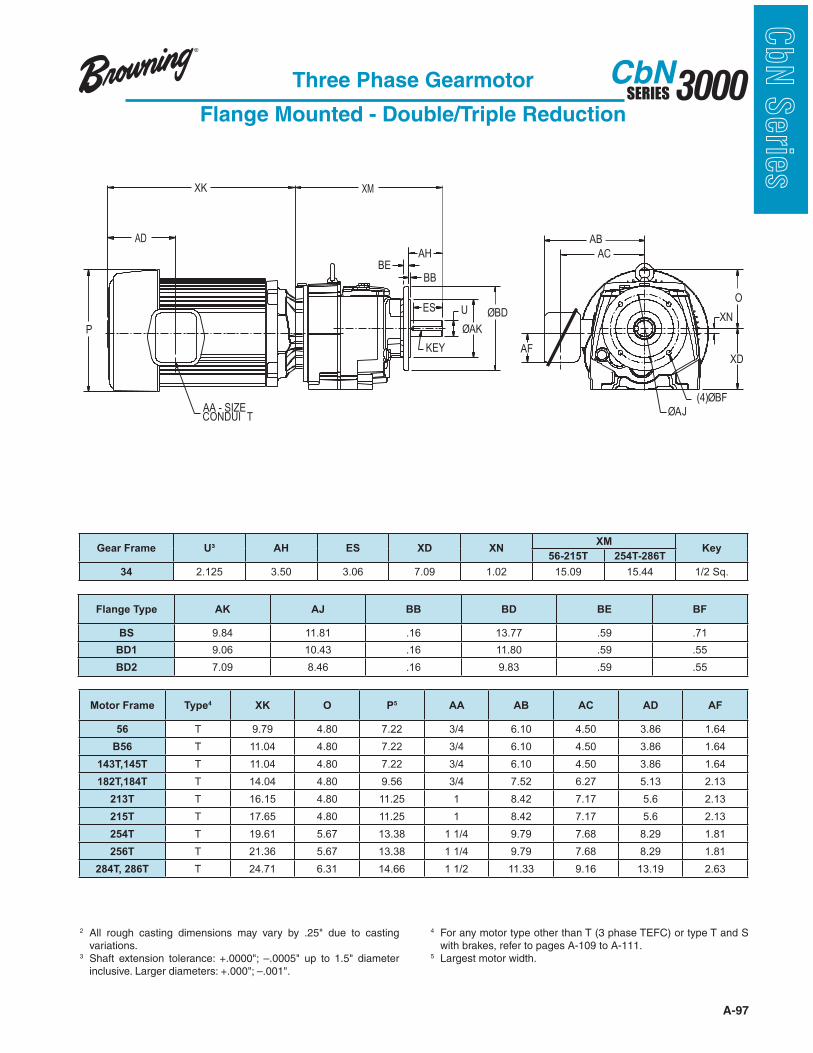
A-97
3000SERIESCbN
CbN
Serie
sThree Phase Gearmotor
Flange Mounted - Double/Triple Reduction
2 variations.
3
4 For any motor type other than T (3 phase TEFC) or type T and S with brakes, refer to pages A-109 to A-111.
5 Largest motor width.
XK
XD
OES U
ØAK
KEY
BB
BE
AH
P
ØBD
ØAJ(4)ØBF
XN
AC
AB
AF
AA - SIZECONDUI T
XM
AD
Motor Frame Type4 XK O P5 AA AB AC AD AF
56 T 9.79 4.80 7.22 3/4 6.10 4.50 3.86 1.64
B56 T 11.04 4.80 7.22 3/4 6.10 4.50 3.86 1.64
143T,145T T 11.04 4.80 7.22 3/4 6.10 4.50 3.86 1.64
182T,184T T 14.04 4.80 9.56 3/4 7.52 6.27 5.13 2.13
213T T 16.15 4.80 11.25 1 8.42 7.17 5.6 2.13
215T T 17.65 4.80 11.25 1 8.42 7.17 5.6 2.13
254T T 19.61 5.67 13.38 1 1/4 9.79 7.68 8.29 1.81
256T T 21.36 5.67 13.38 1 1/4 9.79 7.68 8.29 1.81
284T, 286T T 24.71 6.31 14.66 1 1/2 11.33 9.16 13.19 2.63
Gear Frame U³ AH ES XD XNXM
Key56-215T 254T-286T
34 2.125 3.50 3.06 7.09 1.02 15.09 15.44 1/2 Sq.
Flange Type AK AJ BB BD BE BF
BS 9.84 11.81 .16 13.77 .59 .71
BD1 9.06 10.43 .16 11.80 .59 .55
BD2 7.09 8.46 .16 9.83 .59 .55
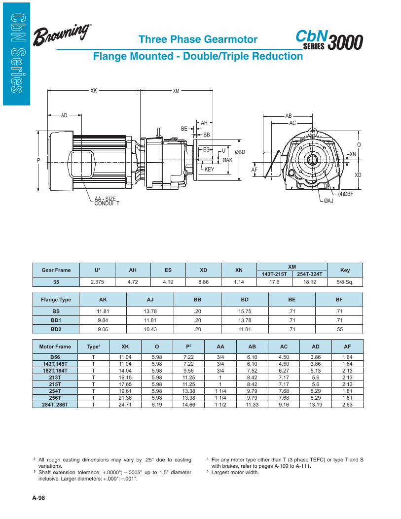
A-98
3000SERIESCbN
CbN
Serie
s
Three Phase Gearmotor
Flange Mounted - Double/Triple Reduction
2 variations.
3
4 For any motor type other than T (3 phase TEFC) or type T and S with brakes, refer to pages A-109 to A-111.
5 Largest motor width.
XK
XD
OES U
ØAK
KEY
BB
BE
AH
P
ØBD
ØAJ(4)ØBF
XN
AC
AB
AF
AA - SIZECONDUI T
XM
AD
Motor Frame Type4 XK O P5 AA AB AC AD AF
B56 T 11.04 5.98 7.22 3/4 6.10 4.50 3.86 1.64
143T,145T T 11.04 5.98 7.22 3/4 6.10 4.50 3.86 1.64
182T,184T T 14.04 5.98 9.56 3/4 7.52 6.27 5.13 2.13
213T T 16.15 5.98 11.25 1 8.42 7.17 5.6 2.13
215T T 17.65 5.98 11.25 1 8.42 7.17 5.6 2.13
254T T 19.61 5.98 13.38 1 1/4 9.79 7.68 8.29 1.81
256T T 21.36 5.98 13.38 1 1/4 9.79 7.68 8.29 1.81
284T, 286T T 24.71 6.19 14.66 1 1/2 11.33 9.16 13.19 2.63
Gear Frame U³ AH ES XD XNXM
Key143T-215T 254T-324T
35 2.375 4.72 4.19 8.86 1.14 17.6 18.12 5/8 Sq.
Flange Type AK AJ BB BD BE BF
BS 11.81 13.78 .20 15.75 .71 .71
BD1 9.84 11.81 .20 13.78 .71 .71
BD2 9.06 10.43 .20 11.81 .71 .55
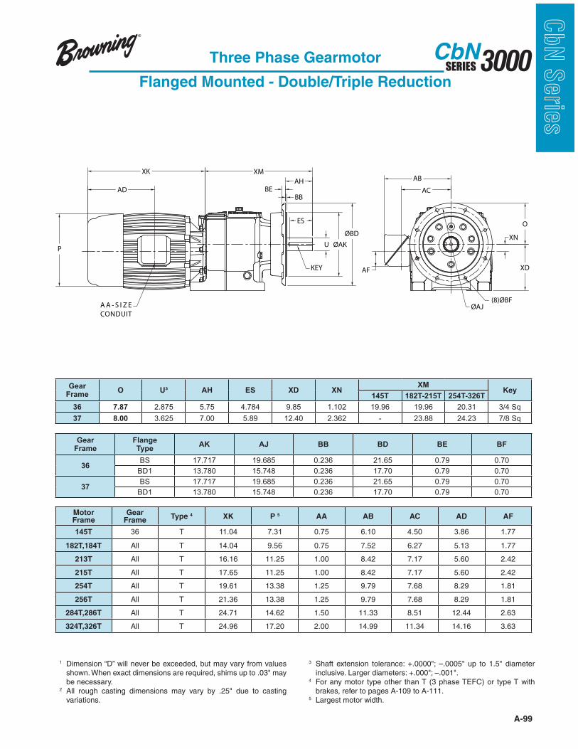
A-99
3000SERIESCbN
CbN
Serie
sThree Phase Gearmotor
Flanged Mounted - Double/Triple Reduction
XN
XM
AF
AB
AC
P
AA - SIZE
CONDUIT
AD
XK
ES
U
BE
AH
BB
KEY
O
XD
ØAJ
(8)ØBF
ØAK
ØBD
AA - S I Z E
CONDUIT
P
AD
XK XM
BE
AH
BB
ES
KEY
ØAK
ØBD
U
AF
AB
AC
XN
XD
O
ØAJ(8)ØBF
GearFrame
FlangeType
AK AJ BB BD BE BF
36BS 17.717 19.685 0.236 21.65 0.79 0.70
BD1 13.780 15.748 0.236 17.70 0.79 0.70
37BS 17.717 19.685 0.236 21.65 0.79 0.70
BD1 13.780 15.748 0.236 17.70 0.79 0.70
Gear Frame
O U³ AH ES XD XNXM
Key145T 182T-215T 254T-326T
36 7.87 2.875 5.75 4.784 9.85 1.102 19.96 19.96 20.31 3/4 Sq
37 8.00 3.625 7.00 5.89 12.40 2.362 - 23.88 24.23 7/8 Sq
MotorFrame
Gear Frame
Type 4 XK P 5 AA AB AC AD AF
145T 36 T 11.04 7.31 0.75 6.10 4.50 3.86 1.77
182T,184T All T 14.04 9.56 0.75 7.52 6.27 5.13 1.77
213T All T 16.16 11.25 1.00 8.42 7.17 5.60 2.42
215T All T 17.65 11.25 1.00 8.42 7.17 5.60 2.42
254T All T 19.61 13.38 1.25 9.79 7.68 8.29 1.81
256T All T 21.36 13.38 1.25 9.79 7.68 8.29 1.81
284T,286T All T 24.71 14.62 1.50 11.33 8.51 12.44 2.63
324T,326T All T 24.96 17.20 2.00 14.99 11.34 14.16 3.63
1 Dimension “D” will never be exceeded, but may vary from values
be necessary.2
variations.
3
4 For any motor type other than T (3 phase TEFC) or type T with brakes, refer to pages A-109 to A-111.
5 Largest motor width.
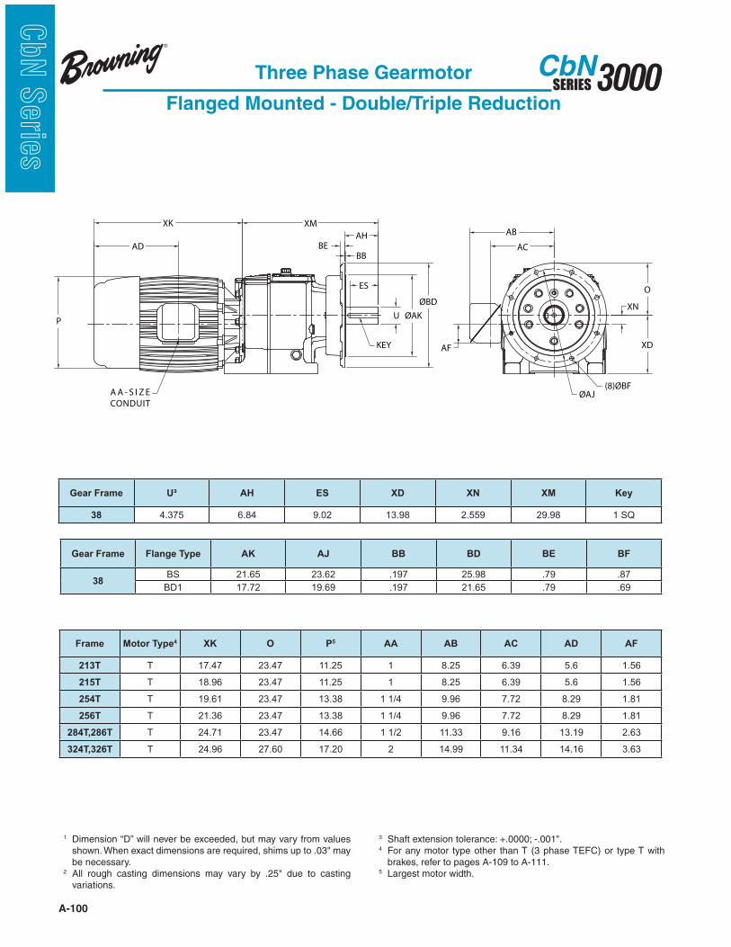
A-100
3000SERIESCbN
CbN
Serie
s
Three Phase Gearmotor
Flanged Mounted - Double/Triple Reduction
1 Dimension “D” will never be exceeded, but may vary from values
be necessary.2
variations.
3 4 For any motor type other than T (3 phase TEFC) or type T with
brakes, refer to pages A-109 to A-111.5 Largest motor width.
Gear Frame U³ AH ES XD XN XM Key
38 4.375 6.84 9.02 13.98 2.559 29.98 1 SQ
Gear Frame Flange Type AK AJ BB BD BE BF
38BS 21.65 23.62 .197 25.98 .79 .87
BD1 17.72 19.69 .197 21.65 .79 .69
XN
XM
AF
AB
AC
P
AA - SIZE
CONDUIT
AD
XK
ES
U
BE
AH
BB
KEY
O
XD
ØAJ
(8)ØBF
ØAK
ØBD
AA - S I Z E
CONDUIT
P
AD
XK XM
BE
AH
BB
ES
KEY
ØAK
ØBD
U
AF
AB
AC
XN
XD
O
ØAJ(8)ØBF
Frame Motor Type4 XK O P5 AA AB AC AD AF
213T T 17.47 23.47 11.25 1 8.25 6.39 5.6 1.56
215T T 18.96 23.47 11.25 1 8.25 6.39 5.6 1.56
254T T 19.61 23.47 13.38 1 1/4 9.96 7.72 8.29 1.81
256T T 21.36 23.47 13.38 1 1/4 9.96 7.72 8.29 1.81
284T,286T T 24.71 23.47 14.66 1 1/2 11.33 9.16 13.19 2.63
324T,326T T 24.96 27.60 17.20 2 14.99 11.34 14.16 3.63
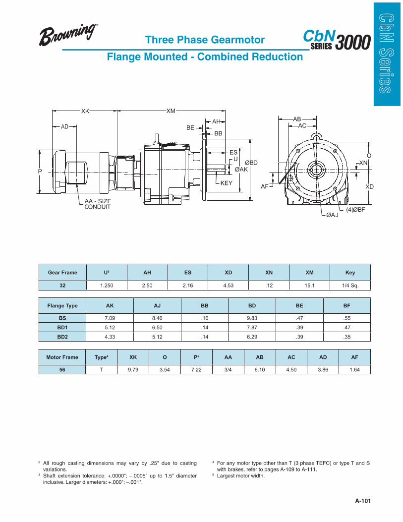
A-101
3000SERIESCbN
CbN
Serie
sThree Phase Gearmotor
Flange Mounted - Combined Reduction
KEY
AA - SIZECONDUIT
ØBD
ØAK
U
ES
BB
AHBE
P
(4)ØBFØAJ
XN
ABAC
AF XD
O
XK XM
AD
2 variations.
3
4 For any motor type other than T (3 phase TEFC) or type T and S with brakes, refer to pages A-109 to A-111.
5 Largest motor width.
Motor Frame Type4 XK O P5 AA AB AC AD AF
56 T 9.79 3.54 7.22 3/4 6.10 4.50 3.86 1.64
Gear Frame U³ AH ES XD XN XM Key
32 1.250 2.50 2.16 4.53 .12 15.1 1/4 Sq.
Flange Type AK AJ BB BD BE BF
BS 7.09 8.46 .16 9.83 .47 .55
BD1 5.12 6.50 .14 7.87 .39 .47
BD2 4.33 5.12 .14 6.29 .39 .35

A-102
3000SERIESCbN
CbN
Serie
s
Three Phase Gearmotor
Flange Mounted - Combined Reduction
KEY
AA - SIZECONDUIT
ØBD
ØAK
U
ES
BB
AHBE
P
(4)ØBFØAJ
XN
ABAC
AF XD
O
XK XM
AD
2 variations.
3
4 For any motor type other than T (3 phase TEFC) or type T and S with brakes, refer to pages A-109 to A-111.
5 Largest motor width.
Motor Frame Type4 XK O P5 AA AB AC AD AF
56 T 9.79 4.43 7.22 3/4 6.10 4.50 3.86 1.64
B56 T 11.04 4.43 7.22 3/4 6.10 4.50 3.86 1.64
143T,145T T 11.04 4.43 7.22 3/4 6.10 4.50 3.86 1.64
Gear Frame U³ AH ES XD XN XM Key
33 1.625 3.15 2.78 5.51 .49 17.88 3/8 Sq.
Flange Type AK AJ BB BD BE BF
BS 9.06 10.43 .16 11.80 .47 .55
BD1 7.09 8.46 .16 9.83 .47 .55
BD2 5.12 6.50 .14 7.86 .47 .47
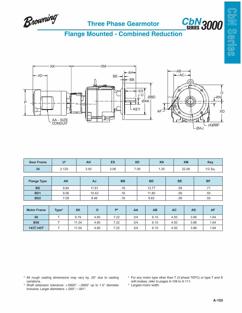
A-103
3000SERIESCbN
CbN
Serie
sThree Phase Gearmotor
Flange Mounted - Combined Reduction
KEY
AA - SIZECONDUIT
ØBD
ØAK
U
ES
BB
AHBE
P
(4)ØBFØAJ
XN
ABAC
AF XD
O
XK XM
AD
2 variations.
3
4 For any motor type other than T (3 phase TEFC) or type T and S with brakes, refer to pages A-109 to A-111.
5 Largest motor width.
Motor Frame Type4 XK O P5 AA AB AC AD AF
56 T 9.79 4.80 7.22 3/4 6.10 4.50 3.86 1.64
B56 T 11.04 4.80 7.22 3/4 6.10 4.50 3.86 1.64
143T,145T T 11.04 4.80 7.22 3/4 6.10 4.50 3.86 1.64
Gear Frame U³ AH ES XD XN XM Key
34 2.125 3.50 3.06 7.09 1.35 22.06 1/2 Sq.
Flange Type AK AJ BB BD BE BF
BS 9.84 11.81 .16 13.77 .59 .71
BD1 9.06 10.43 .16 11.80 .59 .55
BD2 7.09 8.46 .16 9.83 .59 .55
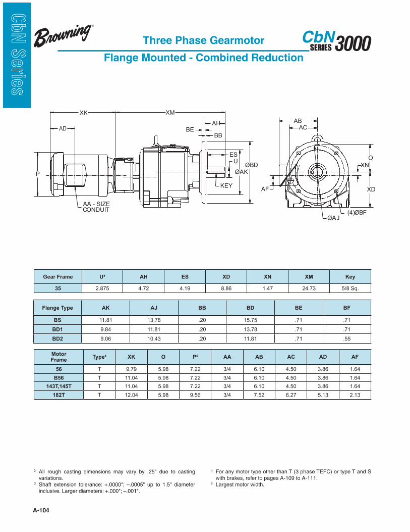
A-104
3000SERIESCbN
CbN
Serie
s
Three Phase Gearmotor
Flange Mounted - Combined Reduction
KEY
AA - SIZECONDUIT
ØBD
ØAK
U
ES
BB
AHBE
P
(4)ØBFØAJ
XN
ABAC
AF XD
O
XK XM
AD
2 variations.
3
4 For any motor type other than T (3 phase TEFC) or type T and S with brakes, refer to pages A-109 to A-111.
5 Largest motor width.
Motor Frame
Type4 XK O P5 AA AB AC AD AF
56 T 9.79 5.98 7.22 3/4 6.10 4.50 3.86 1.64
B56 T 11.04 5.98 7.22 3/4 6.10 4.50 3.86 1.64
143T,145T T 11.04 5.98 7.22 3/4 6.10 4.50 3.86 1.64
182T T 12.04 5.98 9.56 3/4 7.52 6.27 5.13 2.13
Gear Frame U³ AH ES XD XN XM Key
35 2.875 4.72 4.19 8.86 1.47 24.73 5/8 Sq.
Flange Type AK AJ BB BD BE BF
BS 11.81 13.78 .20 15.75 .71 .71
BD1 9.84 11.81 .20 13.78 .71 .71
BD2 9.06 10.43 .20 11.81 .71 .55
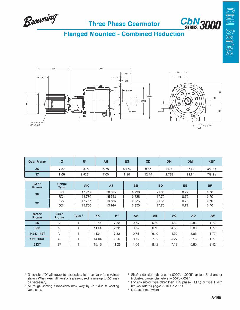
A-105
3000SERIESCbN
CbN
Serie
sThree Phase Gearmotor
Flanged Mounted - Combined Reduction
p
ES
U
KEY
XM
AA - SIZE
CONDUIT
p
XK
AD BE
AH
BB
XN
O
AF
AB
AC
XD
ØAJ
(8)ØBF
ØAK
ØBD
Gear Frame O U³ AH ES XD XN XM KEY
36 7.87 2.875 5.75 4.784 9.85 1.492 27.62 3/4 Sq
37 8.00 3.625 7.00 5.89 12.40 2.752 31.54 7/8 Sq
Motor Frame
Gear Frame
Type 4 XK P 5 AA AB AC AD AF
56 All T 9.79 7.22 0.75 6.10 4.50 3.86 1.77
B56 All T 11.04 7.22 0.75 6.10 4.50 3.86 1.77
143T, 145T All T 11.04 7.22 0.75 6.10 4.50 3.86 1.77
182T,184T All T 14.04 9.56 0.75 7.52 6.27 5.13 1.77
213T 37 T 16.16 11.25 1.00 8.42 7.17 5.60 2.42
1 Dimension “D” will never be exceeded, but may vary from values
be necessary.2
variations.
3
4 For any motor type other than T (3 phase TEFC) or type T with brakes, refer to pages A-109 to A-111.
5 Largest motor width.
GearFrame
FlangeType
AK AJ BB BD BE BF
36BS 17.717 19.685 0.236 21.65 0.79 0.70
BD1 13.780 15.748 0.236 17.70 0.79 0.70
37BS 17.717 19.685 0.236 21.65 0.79 0.70
BD1 13.780 15.748 0.236 17.70 0.79 0.70
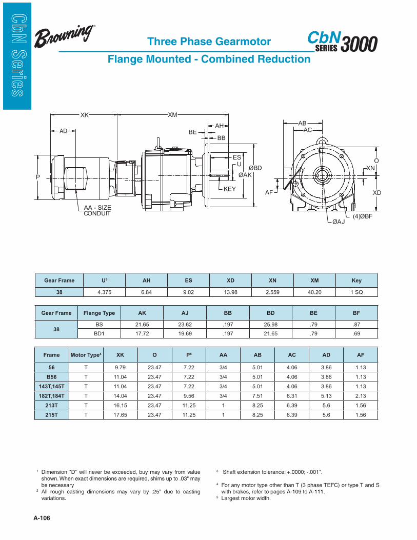
A-106
3000SERIESCbN
CbN
Serie
s
Three Phase Gearmotor
Flange Mounted - Combined Reduction
KEY
AA - SIZECONDUIT
ØBD
ØAK
U
ES
BB
AHBE
P
(4)ØBFØAJ
XN
ABAC
AF XD
O
XK XM
AD
1
be necessary2
variations.
3
4 For any motor type other than T (3 phase TEFC) or type T and S with brakes, refer to pages A-109 to A-111.
5 Largest motor width.
Gear Frame U³ AH ES XD XN XM Key
38 4.375 6.84 9.02 13.98 2.559 40.20 1 SQ
Gear Frame Flange Type AK AJ BB BD BE BF
38BS 21.65 23.62 .197 25.98 .79 .87
BD1 17.72 19.69 .197 21.65 .79 .69
Frame Motor Type4 XK O P5 AA AB AC AD AF
56 T 9.79 23.47 7.22 3/4 5.01 4.06 3.86 1.13
B56 T 11.04 23.47 7.22 3/4 5.01 4.06 3.86 1.13
143T,145T T 11.04 23.47 7.22 3/4 5.01 4.06 3.86 1.13
182T,184T T 14.04 23.47 9.56 3/4 7.51 6.31 5.13 2.13
213T T 16.15 23.47 11.25 1 8.25 6.39 5.6 1.56
215T T 17.65 23.47 11.25 1 8.25 6.39 5.6 1.56

A-107
3000SERIESCbN
CbN
Serie
s
1 Dimension “D” will never be exceeded, but may vary from value shown. When exact dimension is required, shims up to .03” may be required.
2 All rough casting dimensions may vary by .25” due to casting variations.
3 Shaft extension tolerance +.0000”, -.0005” up to 1.5” diameter.4 For any motor types other than T (3 phase TEFC) or for T and S
with brakes, refer to pages A-109 to A111.5 Largest motor width.
Three Phase Gearmotor
Foot Mount with Flange - Double/Triple Reduction
Gear FrameMotor
FrameXK O P5 AA AB AC AD AF XD
3012A
56 9.79 6.88 7.22 3/4 6.10 4.50 3.86 1.64 .08
56B 11.04 6.88 7.22 3/4 6.10 4.50 3.86 1.64 .08
143,145T 11.04 6.88 7.22 3/4 6.10 4.50 3.86 1.64 .08
3013A, 31
56 9.79 6.88 7.22 3/4 6.10 4.50 3.86 .94 .10
56B 11.04 6.88 7.22 3/4 6.10 4.50 3.86 .94 .10
143,145T 11.04 6.88 7.22 3/4 6.10 4.50 3.86 .94 .10
182,184T 14.04 7.99 9.56 3/4 7.52 6.27 5.13 2.13 1.13
Gear Frame Flange Type AH AJ AK BA BB BD BE BF
3012ASBD1 2.06 3.94 3.15 .65 .12 4.72 .28 .28
SBS 2.06 4.53 3.74 .65 .12 5.51 .31 .35
3013ASBD1 2.06 3.94 3.15 .944 .10 4.72 .39 .28
SBS 2.06 4.53 3.74 .944 .14 5.51 .39 .35
31
SBD1 1.50 5.12 4.33 .944 .14 6.29 .39 .35
SBD2 1.50 4.53 3.74 .944 .14 5.51 .39 .35
SBD3 1.50 3.94 3.15 .944 .10 4.72 .39 .28
Gear Frame A B D1 E 2F G H U3 ES XM XN Key
3012A 5.62 5.16 2.95 2.165 4.33 .47 .35 0.750 1.25 4.81 .276 3/16 Sq
3013A 6.76 7.68 3.54 2.170 6.50 .75 .35 0.750 1.25 9.48 -.330 3/16 Sq
31 6.76 7.68 3.54 2.170 6.50 .75 .35 1.000 1.16 9.45 -.330 1/4 Sq
2F
B A
AC
AB
XN
D
XK XM
BE
BB
AH
ES
KEY
BA EE
O
AA - SIZECONDUIT
ØP
(4) H
AF
G
ØUØAK
ØBD
ØAJ
ØBF
AD
P2
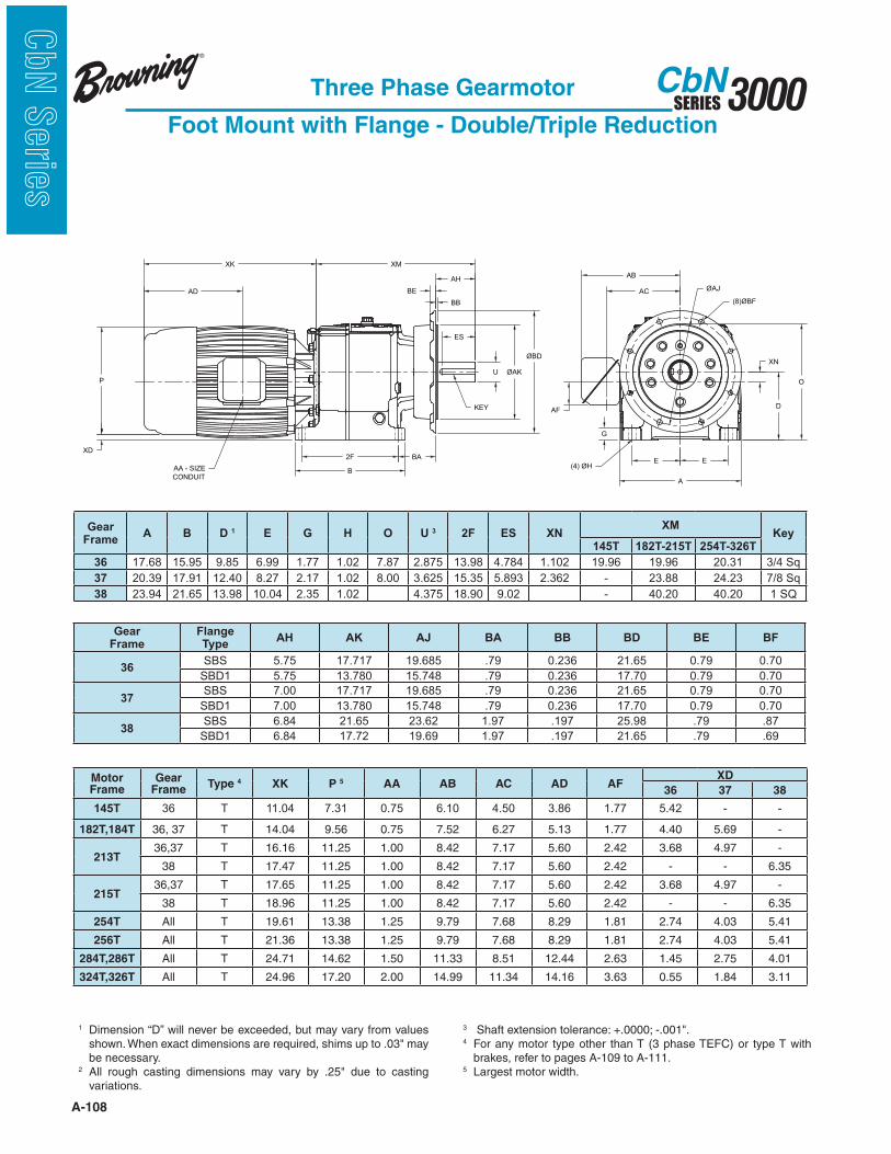
A-108
3000SERIESCbN
CbN
Serie
s
Three Phase Gearmotor
Foot Mount with Flange - Double/Triple Reduction
XN
B
XM
E E
A
G
(4) ØH
DAF
AB
AC
P
XD
AA - SIZE
CONDUIT
AD
XK
2F
ES
U
BE
AH
BB
KEY
BA
O
ØAJ
(8)ØBF
ØAK
ØBD
Gear Frame
Flange Type
AH AK AJ BA BB BD BE BF
36SBS 5.75 17.717 19.685 .79 0.236 21.65 0.79 0.70
SBD1 5.75 13.780 15.748 .79 0.236 17.70 0.79 0.70
37SBS 7.00 17.717 19.685 .79 0.236 21.65 0.79 0.70
SBD1 7.00 13.780 15.748 .79 0.236 17.70 0.79 0.70
38SBS 6.84 21.65 23.62 1.97 .197 25.98 .79 .87
SBD1 6.84 17.72 19.69 1.97 .197 21.65 .79 .69
Gear Frame
A B D 1 E G H O U 3 2F ES XNXM
Key145T 182T-215T 254T-326T
36 17.68 15.95 9.85 6.99 1.77 1.02 7.87 2.875 13.98 4.784 1.102 19.96 19.96 20.31 3/4 Sq
37 20.39 17.91 12.40 8.27 2.17 1.02 8.00 3.625 15.35 5.893 2.362 - 23.88 24.23 7/8 Sq
38 23.94 21.65 13.98 10.04 2.35 1.02 4.375 18.90 9.02 - 40.20 40.20 1 SQ
1 Dimension “D” will never be exceeded, but may vary from values
be necessary.2
variations.
3 4 For any motor type other than T (3 phase TEFC) or type T with
brakes, refer to pages A-109 to A-111.5 Largest motor width.
Motor Frame
Gear Frame
Type 4 XK P 5 AA AB AC AD AFXD
36 37 38
145T 36 T 11.04 7.31 0.75 6.10 4.50 3.86 1.77 5.42 - -
182T,184T 36, 37 T 14.04 9.56 0.75 7.52 6.27 5.13 1.77 4.40 5.69 -
213T36,37 T 16.16 11.25 1.00 8.42 7.17 5.60 2.42 3.68 4.97 -
38 T 17.47 11.25 1.00 8.42 7.17 5.60 2.42 - - 6.35
215T36,37 T 17.65 11.25 1.00 8.42 7.17 5.60 2.42 3.68 4.97 -
38 T 18.96 11.25 1.00 8.42 7.17 5.60 2.42 - - 6.35
254T All T 19.61 13.38 1.25 9.79 7.68 8.29 1.81 2.74 4.03 5.41
256T All T 21.36 13.38 1.25 9.79 7.68 8.29 1.81 2.74 4.03 5.41
284T,286T All T 24.71 14.62 1.50 11.33 8.51 12.44 2.63 1.45 2.75 4.01
324T,326T All T 24.96 17.20 2.00 14.99 11.34 14.16 3.63 0.55 1.84 3.11

A-109
3000SERIESCbN
CbN
Serie
sGearmotor
Alternate Motor Dimensions
rotoM
emarFPH O P 2P AA BA CA DA FA UB KX
652/1,3/1 87.4 82.7 13.3 4/3 87.4 00.4 41.4 31.1 A/N 25.9 2
4/3 87.4 82.7 13.3 4/3 87.4 00.4 41.4 31.1 A/N 20.11 2
T341 1 90.5 82.7 13.3 4/3 87.4 00.4 41.4 31.1 A/N 20.11 2
YT541 2,2/11 35.4 82.7 13.3 4/3 87.4 38.3 41.4 31.1 °5 25.21
T481 5,3 11.5 65.9 93.4 4/3 85.8 54.6 41.7 90.3 A/N 45.61
Single Phase
Corro-Duty®
AD
XK
ØP
P2
AC
AB
BU
AA
Conduit
Size
AF
O
AB
AC
AF
ØP
P2
AA
Conduit
Size
AD
XK
Motor Frame P P2 AA AB AC AD AF XK
56 7.41 3.44 3/4 6.50 4.59 3.72 1.25 10.21 2
143T, 145T 7.41 3.44 3/4 6.50 4.59 3.72 1.25 11.21 2
182T, 184T 9.57 4.33 3/4 3 7.80 6.00 7.79 2.32 14.23
213T, 215T 11 5.44 1 9.47 7.15 9.63 2.00 19.67
254T, 256T 13.31 6.58 1 1/2 11.33 8.51 12.44 2.63 24.26 1
284T, 286T 14.66 7.29 1 1/2 11.33 9.16 13.19 2.63 24.71
1 XK = 23.29 on CbN 33 all reductions.2 XK will increase by .58" if applied to frames 32 and 33 combined units.3 This frame has two openings in conduit box.
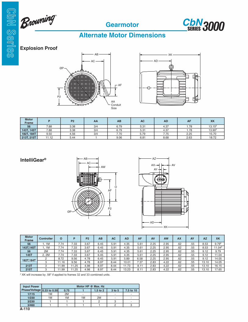
A-110
3000SERIESCbN
CbN
Serie
s
2 XK will increase by .58" if applied to frames 32 and 33 combined units.
rotoM
emarFP 2P AA BA CA DA FA KX
65 88.7 83.3 4/3 97.6 13.5 73.4 87.1 51.312
T541,T341 88.7 83.3 4/3 97.6 13.5 73.4 87.1 09.312
T481,T281 05.9 65.4 4/3 07.7 97.5 57.7 52.2 07.51
T512,T312 21.11 44.5 1 60.9 18.6 86.8 36.2 27.81
AW
AC
AB
O
AF
ØP
AZ
AY
AX
XK
AD
AV
P2
Gearmotor
Alternate Motor Dimensions
AD
XK
AC
AB
AF
ØP
P2
AA
Conduit
Size
rotoM
emarFrellortnoC O P 2P BA CA DA FA VA WA XA YA ZA KX
65 M1,1 47.7 33.7 76.3 54.6 19.5 53.4 16.5 52.2 59.2 26. 55. 35.8 97.9 2
T541,T341 M1,1 47.7 33.7 76.3 54.6 19.5 53.4 16.5 52.2 59.2 26. 55. 35.8 40.11 2
65 M2 47.7 33.7 76.3 54.6 19.5 53.4 16.5 52.2 59.2 26. 55. 21.9 97.9
T541 M2,2 47.7 33.7 76.3 54.6 19.5 53.4 16.5 52.2 59.2 26. 55. 21.9 40.11
T481,T2812 27.8 65.9 87.4 54.6 19.5 98.5 85.6 52.2 59.2 26. 55. 21.9 50.41
3 61.11 65.9 87.4 79.8 44.8 10.01 73.7 38.2 22.4 26. 55. 01.31 50.41
T312 3 99.11 52.11 89.4 79.8 44.8 37.11 11.8 38.2 22.4 26. 55. 01.31 51.61
T512 3 99.11 52.11 89.4 79.8 44.8 32.31 11.8 38.2 22.4 26. 55. 01.31 56.71
rewoPtupnI
egatloV/esahP
zH.xaM@PHrotoM
05.0ot33.0 57.0 1 2ot5.1 5ot3 01ot5.7
511/1 M1 M2 - - - -
032/1 M1 M1 M1 M2 - -
032/3 1 1 1 2 3 -
064/3 1 1 1 1 2 3
Explosion Proof
IntelliGear®
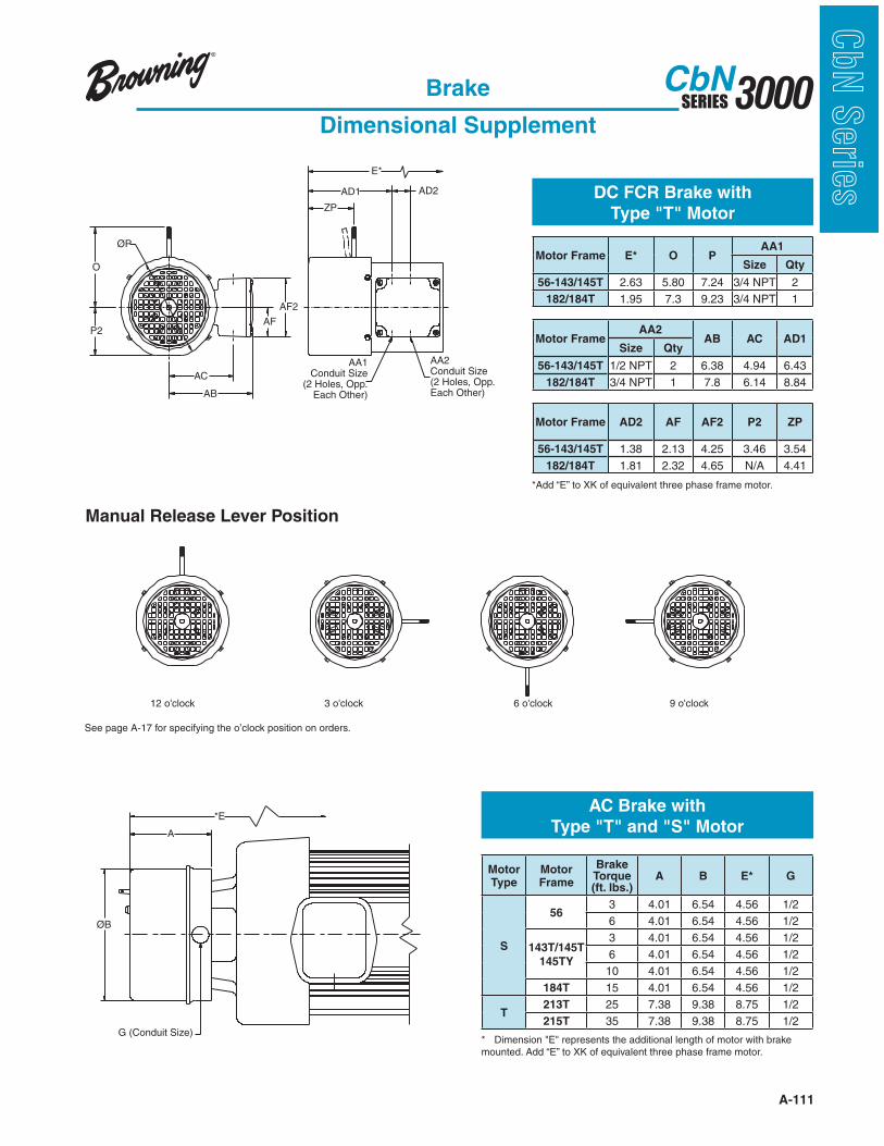
A-111
3000SERIESCbN
CbN
Serie
s
Motor Frame E* O PAA1
Size Qty
56-143/145T 2.63 5.80 7.24 3/4 NPT 2
182/184T 1.95 7.3 9.23 3/4 NPT 1
Motor FrameAA2
AB AC AD1Size Qty
56-143/145T 1/2 NPT 2 6.38 4.94 6.43
182/184T 3/4 NPT 1 7.8 6.14 8.84
Motor Frame AD2 AF AF2 P2 ZP
56-143/145T 1.38 2.13 4.25 3.46 3.54
182/184T 1.81 2.32 4.65 N/A 4.41
Brake
Dimensional Supplement
A
ØB
G (Conduit Size)
*E
ZP
AD1 AD2
P2
AB
AC
ØP
O
AF
AF2
AA2Conduit Size(2 Holes, Opp.Each Other)
AA1Conduit Size
(2 Holes, Opp.Each Other)
E*
AC Brake with
Type "T" and "S" Motor
DC FCR Brake with
Type "T" Motor
Manual Release Lever Position
12 o'clock 3 o'clock 6 o'clock 9 o'clock
See page A-17 for specifying the o’clock position on orders.
Motor Type
MotorFrame
Brake Torque (ft. lbs.)
A B E* G
S
563 4.01 6.54 4.56 1/2
6 4.01 6.54 4.56 1/2
143T/145T
145TY
3 4.01 6.54 4.56 1/2
6 4.01 6.54 4.56 1/2
10 4.01 6.54 4.56 1/2
184T 15 4.01 6.54 4.56 1/2
T213T 25 7.38 9.38 8.75 1/2
215T 35 7.38 9.38 8.75 1/2

A-112
3000SERIESCbN
CbN
Serie
s
Gearmotor
Product Weights (Lbs.)
Foot Mounted Single Reduction - TEFC Three Phase Motor
Optional Motor Types
B14 and Flange Mounted
Weight Adders
Single Reduction Multiple and Combined
Gear
Frame
Motor Frame
56 143T 145T 182T 184T 213T 215T 254T 256T 284T 286T 324T
30 33 35 42 - - - - - - - - -
31 51 55 62 77 87 - - - - - - -
32 56 58 65 80 90 - - - - - - -
33 - 83 85 100 110 147 155 205 - - - -
34 - - - - 113 150 163 213 258 448 498 -
35 - - - - - 200 213 253 308 498 548 728
TypeMotor Frame
56 143T 145T 145TY 182T 184T 213T 215T 254T 256T 284T 286T 320T
C Corro-Duty 8 9 11 11 52 50 73 70 190 165 - - RO
X Explosionproof 19 21 25 - 33 30 50 50 - - - - -
S Single Phase 6 11 - 5 - 17 - - - - - - -
IG IntelliGear 7 15 18 20 31 30 51 53 - - - - -
Gear
Frame
B14 Face
Mount
Flange
Mount
Gear
Frame
B14 Face
Mount
Flange
Mount
30 0 1 30 0 1
31 -1 3 31 -1 2
32 -1 4 32 -1 4
33 -1 8 33 -3 8
34 -2 8 34 -5 8
35 -2 9 35 -6 9
36 0 21
37 0 21
38 0 35
Foot Mounted Multiple Reduction - TEFC Three Phase Motor
Gear
FrameStages
Motor Frame
56 143T 145T 182T 184T 213T 215T 254T 256T 284T 286T 320T30 2, 3 39 41 48 - - - - - - - - -31 2, 3 65 67 75 90 100 - - - - - - -
322, 3 78 80 87 102 112 144 152 - - - - -4, 5 86 88 - - - - - - - - - -
332, 3 107 109 115 132 142 184 192 240 - - - -4, 5 117 119 - - - - - - - - - -
342, 3 130 132 138 156 166 204 212 249 299 489 539 -4, 5 129 131 138 - - - - - - - - -
352, 3 - 225 230 249 259 290 298 348 398 588 638 8184, 5 234 236 243 257 267 - - - - - -
362,3 - - 350 366 367 400 408 458 508 768 818 998
4,5,6 399 408 412 - - - - - - - - -
372,3 - - - 465 475 499 507 557 607 867 917 1097
4,5,6 454 463 467 488 498 522 - - - - - -
383 - - - - - 818 826 876 926 1186 1236 1416
4,5,6 799 808 812 833 843 867 880 - - - - -

A-113
3000SERIESCbN
CbN
Serie
sType CbN Helical In-line
Series 3000 Speed Reducer
Features...
Design Features
1
3
5
1. Gear reducers are delivered factory filled with synthetic hydrocarbon lubricant.
2. Cast one-piece housing/endshield construction provides added strength and rigidity.
3. Series 3000 C-Face reducers utilize compact quill construction with two bearings for support and the quill has a non-metallic liner to eliminate fretting.
4. oil checks
5. All gears are keyed to shafts and finished to provide quiet operation.
6. Oversized bearings are used to help provide longer life.
4
6
4
2
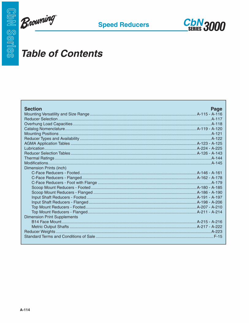
A-114
3000SERIESCbN
CbN
Serie
s
Section PageMounting Versatility and Size Range ..............................................................................................A-115 - A-116Reducer Selection .......................................................................................................................................A-117Overhung Load Capacities ..........................................................................................................................A-118 Catalog Nomenclature ....................................................................................................................A-119 - A-120Mounting Positions ......................................................................................................................................A-121 Reducer Types and Availability ....................................................................................................................A-122AGMA Application Tables ...............................................................................................................A-123 - A-125Lubrication ......................................................................................................................................A-224 - A-225Reducer Selection Tables ...............................................................................................................A-126 - A-143Thermal Ratings ..........................................................................................................................................A-144Modifications ................................................................................................................................................A-145Dimension Prints (inch) C-Face Reducers - Footed .......................................................................................................A-146 - A-161 C-Face Reducers - Flanged .....................................................................................................A-162 - A-178 C-Face Reducers - Foot with Flange ....................................................................................................A-179 Scoop Mount Reducers - Footed .............................................................................................A-180 - A-185 Scoop Mount Reducers - Flanged ...........................................................................................A-186 - A-190 Input Shaft Reducers - Footed .................................................................................................A-191 - A-197 Input Shaft Reducers - Flanged ...............................................................................................A-198 - A-206 Top Mount Reducers - Footed ..................................................................................................A-207 - A-210 Top Mount Reducers - Flanged ................................................................................................A-211 - A-214Dimension Print Supplements B14 Face Mount .......................................................................................................................A-215 - A-216 Metric Output Shafts ................................................................................................................A-217 - A-222Reducer Weights .........................................................................................................................................A-223Standard Terms and Conditions of Sale ........................................................................................................F-15
Table of Contents
Speed Reducers
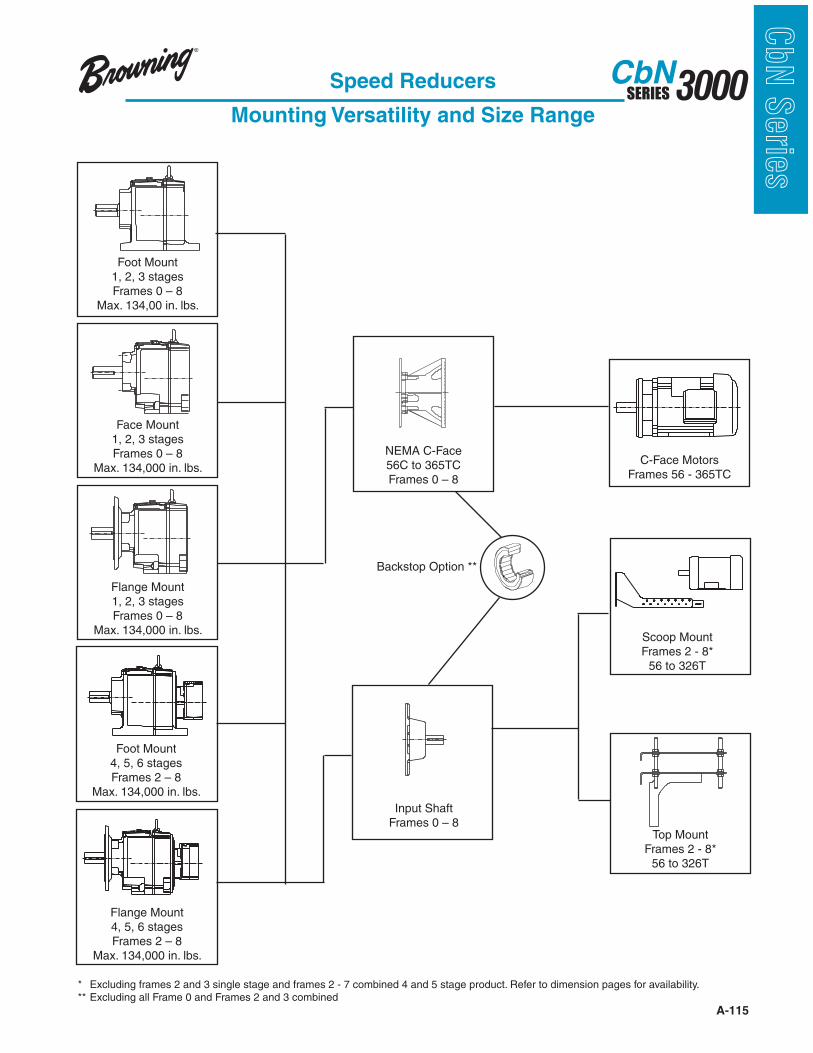
A-115
3000SERIESCbN
CbN
Serie
sSpeed Reducers
Mounting Versatility and Size Range
Foot Mount1, 2, 3 stagesFrames 0 – 8
Max. 134,00 in. lbs.
Face Mount1, 2, 3 stagesFrames 0 – 8
Max. 134,000 in. lbs.
Flange Mount1, 2, 3 stagesFrames 0 – 8
Max. 134,000 in. lbs.
Foot Mount4, 5, 6 stagesFrames 2 – 8
Max. 134,000 in. lbs.
Flange Mount4, 5, 6 stagesFrames 2 – 8
Max. 134,000 in. lbs.
NEMA C-Face56C to 365TCFrames 0 – 8
Input ShaftFrames 0 – 8
Top MountFrames 2 - 8*
56 to 326T
Scoop MountFrames 2 - 8*
56 to 326T
C-Face MotorsFrames 56 - 365TC
Backstop Option **
* Excluding frames 2 and 3 single stage and frames 2 - 7 combined 4 and 5 stage product. Refer to dimension pages for availability.** Excluding all Frame 0 and Frames 2 and 3 combined
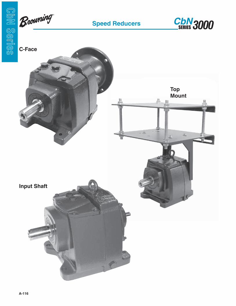
A-116
3000SERIESCbN
CbN
Serie
s
Speed Reducers
C-Face
Top
Mount
Input Shaft
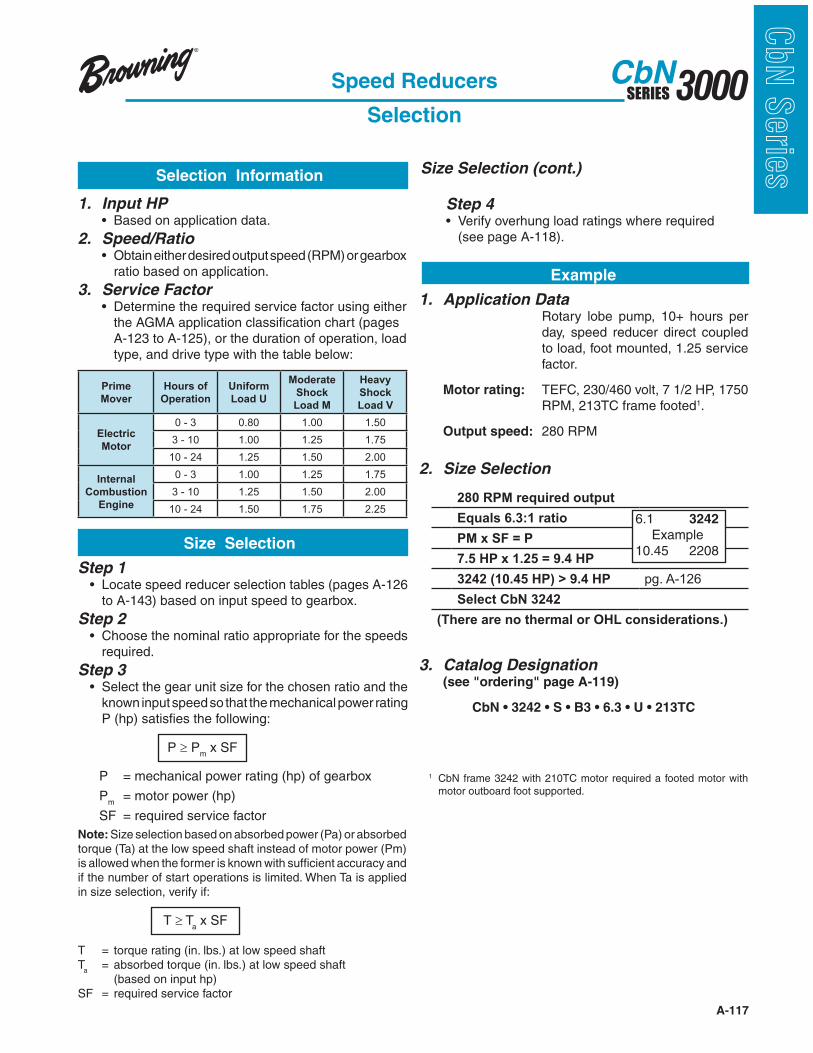
A-117
3000SERIESCbN
CbN
Serie
s
1. Application Data Rotary lobe pump, 10+ hours per
day, speed reducer direct coupled to load, foot mounted, 1.25 service factor.
Motor rating: TEFC, 230/460 volt, 7 1/2 HP, 1750 RPM, 213TC frame footed1.
Output speed: 280 RPM
2. Size Selection
3. Catalog Designation (see "ordering" page A-119)
280 RPM required output
Equals 6.3:1 ratio
PM x SF = P
7.5 HP x 1.25 = 9.4 HP
3242 (10.45 HP) > 9.4 HP pg. A-126
Select CbN 3242
(There are no thermal or OHL considerations.)
Speed Reducers
Selection
1. Input HP 2. Speed/Ratio
ratio based on application.
3. Service Factor
the AGMA application classification chart (pages A-123 to A-125), or the duration of operation, load
type, and drive type with the table below:
Step 1
to A-143) based on input speed to gearbox.
Step 2
required.
Step 3
known input speed so that the mechanical power rating P (hp) satisfies the following:
P Pm x SF
P = mechanical power rating (hp) of gearbox
Pm = motor power (hp)
SF = required service factor
Note: Size selection based on absorbed power (Pa) or absorbed torque (Ta) at the low speed shaft instead of motor power (Pm) is allowed when the former is known with sufficient accuracy and if the number of start operations is limited. When Ta is applied in size selection, verify if:
T Ta x SF
T = torque rating (in. lbs.) at low speed shaftT
a = absorbed torque (in. lbs.) at low speed shaft
(based on input hp)SF = required service factor
Size Selection (cont.)Selection Information
Size Selection
Example
Step 4 (see page A-118).
6.1 3242
Example10.45 2208
Prime
Mover
Hours of
Operation
Uniform
Load U
Moderate
Shock
Load M
Heavy
Shock
Load V
Electric
Motor
0 - 3 0.80 1.00 1.50
3 - 10 1.00 1.25 1.75
10 - 24 1.25 1.50 2.00
Internal
Combustion
Engine
0 - 3 1.00 1.25 1.75
3 - 10 1.25 1.50 2.00
10 - 24 1.50 1.75 2.25
1 CbN frame 3242 with 210TC motor required a footed motor with motor outboard foot supported.
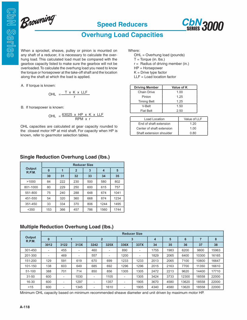
A-118
3000SERIESCbN
CbN
Serie
s When a sprocket, sheave, pulley or pinion is mounted on any shaft of a reducer, it is necessary to calculate the over-hung load. This calculated load must be compared with the gearbox capacity listed to make sure the gearbox will not be overloaded. To calculate the overhung load you need to know the torque or horsepower at the take-off shaft and the location along the shaft at which the load is applied.
A. If torque is known: OHL =
B. If horsepower is known: OHL =
T x K x LLF
r
Where: OHL = Overhung load (pounds) T = Torque (in. lbs.) r = Radius of driving member (in.) HP = Horsepower K = Drive type factor LLF = Load location factor
63025 x HP x K x LLF
RPM x r
Speed Reducers
Overhung Load Capacities
OHL capacities are calculated at gear capacity rounded to the closest motor HP at mid shaft. For capacity when HP is known, refer to gearmotor selection tables.
Single Reduction Overhung Load (lbs.)
Minimum OHL capacity based on minimum recommended sheave diameter and unit driven by maximum motor HP.
Multiple Reduction Overhung Load (lbs.)
Driving Member Value of K
Chain Drive 1.00
Pinion 1.25
Timing Belt 1.25
V-Belt 1.50
Flat Belt 2.50
Load Location Value of LLF
End of shaft extension 1.20
Center of shaft extension 1.00
Shaft extension shoulder 0.80
Output
R.P.M.
Reducer Size
0 1 2 3 4 5
30 31 32 33 34 35
>1000 84 222 230 500 580 802
801-1000 80 229 250 600 615 757
551-800 75 240 288 648 674 1041
451-550 54 320 360 668 874 1234
351-450 33 334 370 806 1244 1495
<350 153 366 457 786 1560 1744
Output
R.P.M.
Reducer Size
0 1 2 3 4 5 6 7 8
3012 3122 313X 3242 325X 336X 337X 34 35 36 37 38
301-450 - 455 - 460 - 890 - 1755 1983 6200 9800 15963
201-300 - 469 - 557 - 1200 - 1829 2065 6400 10300 16165
151-200 129 591 619 670 699 1233 1233 2013 2065 7100 10800 16647
101-150 138 603 649 685 692 1296 1296 2015 2163 7700 11350 16610
51-100 388 701 714 850 856 1305 1305 2472 2213 9620 14400 17710
31-50 600 - 1030 - 1105 - 1305 3424 3733 12300 18558 22000
16-30 600 - 1297 - 1357 - 1905 3670 4580 13620 18558 22000
<15 600 - 1345 - 1610 - 1905 4340 4580 13620 18558 22000
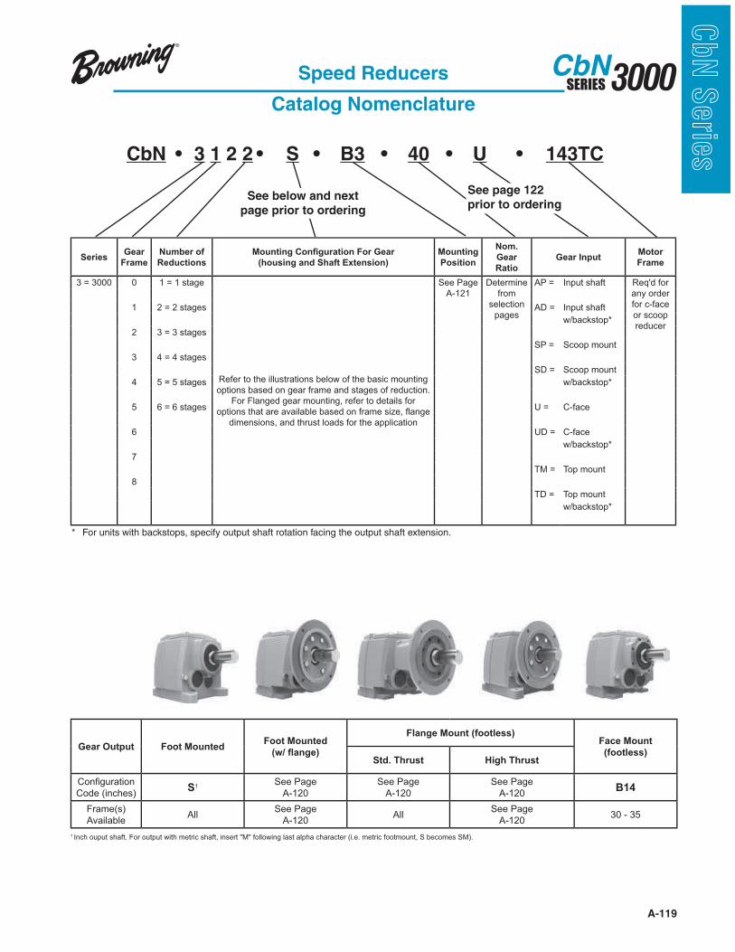
A-119
3000SERIESCbN
CbN
Serie
s
SeriesGear
Frame
Number of
Reductions
!"#$%#&'(!#)'&"*+$%!#',!*'-.+*
(housing and Shaft Extension)
Mounting
Position
Nom.
Gear
Ratio
Gear InputMotor
Frame
3 = 3000 0 1 = 1 stage
Refer to the illustrations below of the basic mounting
options based on gear frame and stages of reduction.
For Flanged gear mounting, refer to details for
!"# $%&"'("&()*&(+(#,(-,*&-(%*.& $&/)(0*&%#1*2&3&($4*&
dimensions, and thrust loads for the application
See Page
A-121
Determine
from
selection
pages
AP = Input shaft Req'd for
any order
for c-face
or scoop
reducer
1 2 = 2 stages AD = Input shaft
w/backstop*
2 3 = 3 stages
SP = Scoop mount
3 4 = 4 stages
SD = Scoop mount
4 5 = 5 stages w/backstop*
5 6 = 6 stages U = C-face
6 UD = C-face
w/backstop*
7
TM = Top mount
8
TD = Top mount
w/backstop*
Speed Reducers
Catalog Nomenclature
* For units with backstops, specify output shaft rotation facing the output shaft extension.
CbN 3 1 2 2 S B3 40 U 143TC
See below and next
page prior to ordering
See page 122
prior to ordering
Gear Output Foot MountedFoot Mounted
/01'2'+#&.3
Flange Mount (footless)Face Mount
(footless)Std. Thrust High Thrust
5 $6&47)("# $&
Code (inches)S1
See Page
A-120
See Page
A-120
See Page
A-120B14
Frame(s)
AvailableAll
See Page
A-120All
See Page
A-12030 - 35
1 Inch ouput shaft. For output with metric shaft, insert "M" following last alpha character (i.e. metric footmount, S becomes SM).
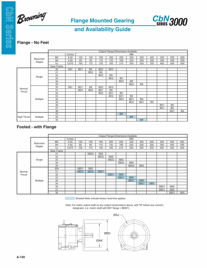
A-120
3000SERIESCbN
CbN
Serie
s Flange - No Feet
Flange Mounted Gearing
and Availability Guide
Output Flange Dimensions Available
Reduction
Stages
Inches MM
BD 6.50 120 140 160 200 250 300 350 400 450 550 650
AK 4.50 80 95 110 130 180 230 250 300 350 450 550
AJ 5.875 100 115 130 165 215 254 300 350 400 500 600
Gear Frame
Normal
Thrust
Single
30 56C BD1 BS BD2 BD3
31 BD2 BS
32 BD2 BS
33 BD2 BS
34 BD2 BS
35 BD2 BS
Multiple
30 56C BD1 BS BD2 BD3
31 BD3 BD2 BD1 BS
32 BD2 BD1 BS
33 BD2 BD1 BS
34 BD2 BD1 BS
35 BD2 BD1 BS
36 BD1 BS
37 BD1 BS
38 BD1 BS
High Thrust Multiple
33 BR
34 BR
35 BR
Output Flange Dimensions Available
Reduction
Stages
Inches MM
BD 6.50 120 140 160 200 250 300 350 400 450 550 650
AK 4.50 80 95 110 130 180 230 250 300 350 450 550
AJ 5.875 100 115 130 165 215 254 300 350 400 500 600
Gear Frame
Normal
Thrust
Single
31 SBD2 SBS
32 SBD2 SBS
33 SBD2 SBS
34 SBD2 SBS
35 SBD2 SBS
Multiple
30A SBD1 SBS
31 SBD3 SBD2 SBD1
32 SBD1 SBS
33 SBD1 SBS
34 SBD1 SBS
35 SBD1 SBS
36 SBD1 SBS
37 SBD1 SBS
38 SBD1 SBS
Footed - with Flange
8'(.*.&6*,.%&#$.#9("*&/(9" ):&,*(.;"#0*&(!!,#*%
Note: For metric output shaft on any output nomenclature above, add "M" before any numeric
& & & .*%#4$(" )<&=#<*<&0*")#9&%'(/"&>#"'&?@A&3($4*&B&?@CAD
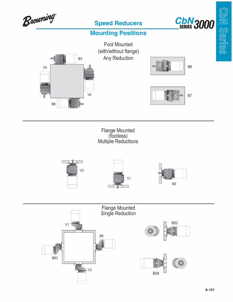
A-121
3000SERIESCbN
CbN
Serie
sSpeed Reducers
Mounting Positions
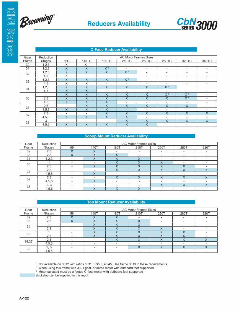
A-122
3000SERIESCbN
CbN
Serie
s
1 Not available on 3012 with ratios of 31.5, 35.5, 40,45. Use frame 3013 in these requirements2 When using this frame with 3301 gear, a footed motor with outboard foot supported.3 Motor selected must be a footed C-face motor with outboard foot supported
Backstop can be supplied in this input.
C-Face Reducer Availability
Gear Frame
Reduction Stages
AC Motor Frames Sizes
56C 140TC 180TC 210TC 250TC 280TC 320TC 360TC
30 1,2,3 X X 1 - - - - - -
31 1,2,3 X X X 3 - - - - -
321,2.3 X X X X 3 - - - -
4,5 X - - - -
331,2,3 X X X X 2 - - - -
4,5 X X - - - - - -
341,2,3 X X X X X X 3
4,5 X X - - - - - -
35
1 X X X X X X 3 X 3 -
2,3 X X X X X X X 3 -
4,5 X X X - - - - -
362,3 - X X X X X X -
4,5,6 X X X - - - - -
372,3 - - X X X X X X
4,5,6 X X X X - - - -
383 - - - X X X X X
4,5,6 X X X X X - - -
Scoop Mount Reducer Availability
Gear Frame
Reduction Stages
AC Motor Frames Sizes
56 140T 180T 210T 250T 280T 320T
32 2,3 X X - - - - -
33 2,3 X X X - - - -
34 1,2,3 - X X X - - -
351 - - X X X - -
2,3 - X X X X X -
362,3 - - X X X X X
4,5,6 - X - - - - -
372,3 - - X X X X X
4,5,6 - X - - - - -
382, 3 - - - - X X X
4,5,6 - X X X - - -
Top Mount Reducer Availability
Gear Frame
Reduction Stages
AC Motor Frames Sizes
56 140T 180T 210T 250T 280T 320T
32 2,3 X X X - - - -
33 2,3 X X X X - - -
341 X X X - - -
2,3 - X X X X - -
351 - X X X X X -
2,3 - X X X X X -
36,372,3 - - X X X X X
4,5,6 - - - - - - -
382, 3 - - - X X X X
4,5,6 - - - - - -
Reducers Availability

A-123
3000SERIESCbN
CbN
Serie
sSpeed Reducers
AGMA Application Classifications
U: Uniform load M: Moderate shock load V: Heavy shock load
Application Load Class Application Load Class Application Load Class
Up to Up to Over
3 10 10
hrs/day hrs/day hrs/day
Agitators (Mixers)
Pure Liquids — 1.00 1.25 Liquids & Solids 1.00 1.25 1.50 Liquids - Variable Density 1.00 1.25 1.50
Blowers
Centrifugal 1.00 1.25 — Lobe 1.00 1.25 1.50 Vane — 1.00 1.25
Brewing and Distillers
Bottling Machinery — 1.00 1.25 Brew Kettles, Continuous Duty — 1.00 1.25 Cookers - Continuous Duty — 1.00 1.25 Mash Tubs - Continuous Duty — 1.00 1.25 Scale Hoppers, Frequent Starts 1.00 1.25 1.50
Can Filling Machines — 1.00 1.25
Car Dumpers 1.25 1.50 1.75
Car Pullers 1.00 1.25 1.50
Clarifiers — 1.00 1.25
Classifiers 1.00 1.25 1.50
Clayworking Industry
Brick Press 1.25 1.50 1.75 Briquette Machine 1.25 1.50 1.75 Pug Mill 1.00 1.25 1.50
Compactors 1.50 1.75 2.00
Compressors
Centrifugal — 1.00 1.25 Lobe 1.00 1.25 1.50 Reciprocating, Multi - Cylinder 1.00 1.25 1.50 Reciprocating, Single - Cylinder 1.25 1.50 1.75
Conveyors - General Purpose
Uniformly Loaded or Fed — 1.00 1.25 Not Uniformly Fed 1.00 1.25 1.50 Reciprocating or Shaker 1.25 1.50 1.75
Cranes
Dry Dock Main Hoist 1.25 1.50 1.75 Auxiliary 1.25 1.50 1.75 Boom Hoist 1.25 1.50 1.75 Slewing Drive 1.25 1.50 1.75 Traction Drive 1.50 1.50 1.50 Container Main Hoist Refer To Application Engineering
Cranes (Continued)
Boom Hoist Refer To Application Engineering Trolley Drive Refer To Application Engineering (Gantry Drive) (Traction Drive) Refer To Application Engineering Mill Duty Main Refer To Application Engineering Auxiliary Refer To Application Engineering Bridge & Trolley Travel Refer To Application Engineering Industrial Duty Main 1.25 1.50 1.75 Auxiliary Refer To Application Engineering Bridge & Trolley Travel Refer To Application Engineering
Crusher
Stone or Ore 1.50 1.75 2.00
Dredges
Cable Reels 1.00 1.25 1.50 Conveyors 1.00 1.25 1.50 Cutter Head Drives 1.25 1.50 1.75 Pumps 1.00 1.25 1.50 Screen Drives 1.25 1.50 1.75 Stackers 1.00 1.25 1.50 Winches 1.00 1.25 1.50
Elevators
Bucket 1.00 1.25 1.50 Centrifugal Discharge — 1.00 1.25 Escalators Refer To Application Engineering Freight Refer To Application Engineering Gravity Discharge — 1.00 1.25
Extruders
General 1.25 1.25 1.25 Plastics (a) Variable Speed Drive 1.50 1.50 1.50 (b) Fixed Speed Drive 1.75 1.75 1.75 Rubber (a) Continuous Screw Operation 1.50 1.50 1.50 (b) Intermittent Screw Operation 1.75 1.75 1.75
Fans
Centrifugal — 1.00 1.25 Cooling Towers Refer To Application Engineering Forced Draft 1.25 1.25 1.25 Induced Draft 1.00 1.25 1.50 Industrial & Mine 1.00 1.25 1.50
Up to Up to Over
3 10 10
hrs/day hrs/day hrs/day
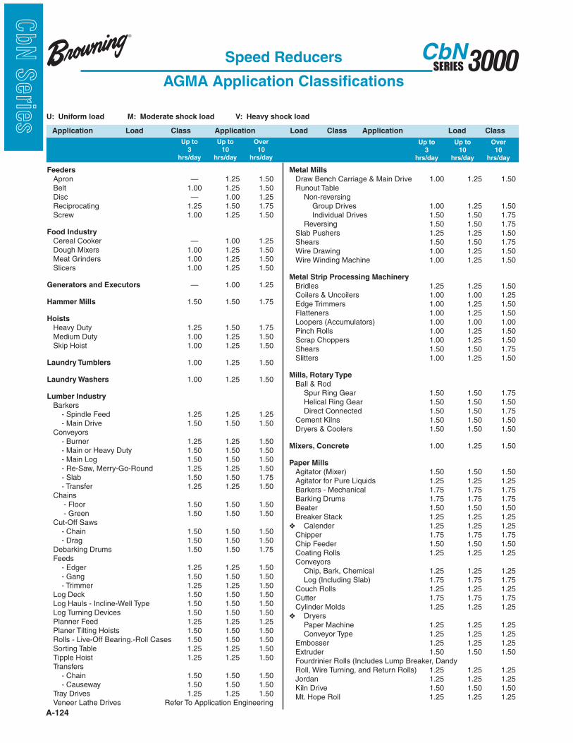
A-124
3000SERIESCbN
CbN
Serie
s U: Uniform load M: Moderate shock load V: Heavy shock load
Application Load Class Application Load Class Application Load Class
Feeders
Apron — 1.25 1.50 Belt 1.00 1.25 1.50 Disc — 1.00 1.25 Reciprocating 1.25 1.50 1.75 Screw 1.00 1.25 1.50
Food Industry
Cereal Cooker — 1.00 1.25 Dough Mixers 1.00 1.25 1.50 Meat Grinders 1.00 1.25 1.50 Slicers 1.00 1.25 1.50
Generators and Executors — 1.00 1.25
Hammer Mills 1.50 1.50 1.75
Hoists
Heavy Duty 1.25 1.50 1.75 Medium Duty 1.00 1.25 1.50 Skip Hoist 1.00 1.25 1.50
Laundry Tumblers 1.00 1.25 1.50
Laundry Washers 1.00 1.25 1.50
Lumber Industry
Barkers - Spindle Feed 1.25 1.25 1.25 - Main Drive 1.50 1.50 1.50 Conveyors - Burner 1.25 1.25 1.50 - Main or Heavy Duty 1.50 1.50 1.50 - Main Log 1.50 1.50 1.50 - Re-Saw, Merry-Go-Round 1.25 1.25 1.50 - Slab 1.50 1.50 1.75 - Transfer 1.25 1.25 1.50 Chains - Floor 1.50 1.50 1.50 - Green 1.50 1.50 1.50 Cut-Off Saws - Chain 1.50 1.50 1.50 - Drag 1.50 1.50 1.50 Debarking Drums 1.50 1.50 1.75 Feeds - Edger 1.25 1.25 1.50 - Gang 1.50 1.50 1.50 - Trimmer 1.25 1.25 1.50 Log Deck 1.50 1.50 1.50 Log Hauls - Incline-Well Type 1.50 1.50 1.50 Log Turning Devices 1.50 1.50 1.50 Planner Feed 1.25 1.25 1.25 Planer Tilting Hoists 1.50 1.50 1.50 Rolls - Live-Off Bearing.-Roll Cases 1.50 1.50 1.50 Sorting Table 1.25 1.25 1.50 Tipple Hoist 1.25 1.25 1.50 Transfers - Chain 1.50 1.50 1.50 - Causeway 1.50 1.50 1.50 Tray Drives 1.25 1.25 1.50 Veneer Lathe Drives Refer To Application Engineering
Metal Mills
Draw Bench Carriage & Main Drive 1.00 1.25 1.50 Runout Table Non-reversing Group Drives 1.00 1.25 1.50 Individual Drives 1.50 1.50 1.75 Reversing 1.50 1.50 1.75 Slab Pushers 1.25 1.25 1.50 Shears 1.50 1.50 1.75 Wire Drawing 1.00 1.25 1.50 Wire Winding Machine 1.00 1.25 1.50
Metal Strip Processing Machinery
Bridles 1.25 1.25 1.50 Coilers & Uncoilers 1.00 1.00 1.25 Edge Trimmers 1.00 1.25 1.50 Flatteners 1.00 1.25 1.50 Loopers (Accumulators) 1.00 1.00 1.00 Pinch Rolls 1.00 1.25 1.50 Scrap Choppers 1.00 1.25 1.50 Shears 1.50 1.50 1.75 Slitters 1.00 1.25 1.50
Mills, Rotary Type
Ball & Rod Spur Ring Gear 1.50 1.50 1.75 Helical Ring Gear 1.50 1.50 1.50 Direct Connected 1.50 1.50 1.75 Cement Kilns 1.50 1.50 1.50 Dryers & Coolers 1.50 1.50 1.50
Mixers, Concrete 1.00 1.25 1.50
Paper Mills
Agitator (Mixer) 1.50 1.50 1.50 Agitator for Pure Liquids 1.25 1.25 1.25 Barkers - Mechanical 1.75 1.75 1.75 Barking Drums 1.75 1.75 1.75 Beater 1.50 1.50 1.50 Breaker Stack 1.25 1.25 1.25 Calender 1.25 1.25 1.25 Chipper 1.75 1.75 1.75 Chip Feeder 1.50 1.50 1.50 Coating Rolls 1.25 1.25 1.25 Conveyors Chip, Bark, Chemical 1.25 1.25 1.25 Log (Including Slab) 1.75 1.75 1.75 Couch Rolls 1.25 1.25 1.25 Cutter 1.75 1.75 1.75 Cylinder Molds 1.25 1.25 1.25 Dryers Paper Machine 1.25 1.25 1.25 Conveyor Type 1.25 1.25 1.25 Embosser 1.25 1.25 1.25 Extruder 1.50 1.50 1.50 Fourdrinier Rolls (Includes Lump Breaker, Dandy Roll, Wire Turning, and Return Rolls) 1.25 1.25 1.25 Jordan 1.25 1.25 1.25 Kiln Drive 1.50 1.50 1.50 Mt. Hope Roll 1.25 1.25 1.25
Up to Up to Over
3 10 10
hrs/day hrs/day hrs/day
Up to Up to Over
3 10 10
hrs/day hrs/day hrs/day
Speed Reducers
AGMA Application Classifications
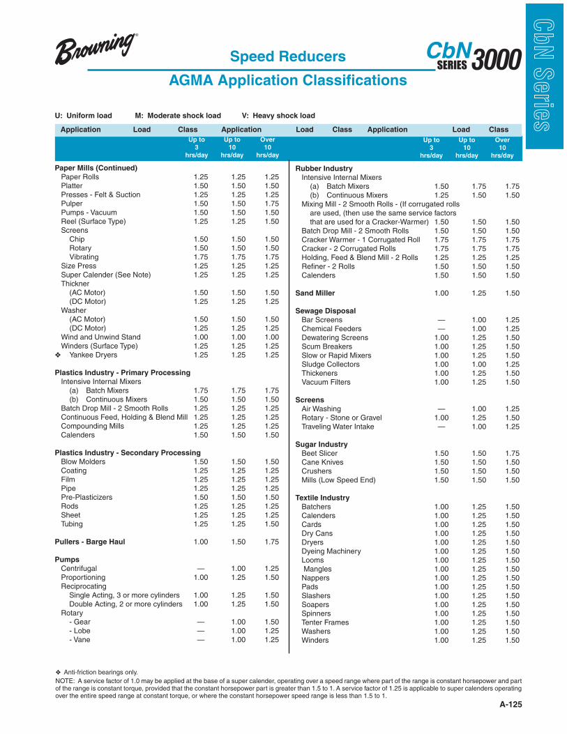
A-125
3000SERIESCbN
CbN
Serie
sSpeed Reducers
AGMA Application Classifications
U: Uniform load M: Moderate shock load V: Heavy shock load
Application Load Class Application Load Class Application Load Class
Paper Mills (Continued)
Paper Rolls 1.25 1.25 1.25 Platter 1.50 1.50 1.50 Presses - Felt & Suction 1.25 1.25 1.25 Pulper 1.50 1.50 1.75 Pumps - Vacuum 1.50 1.50 1.50 Reel (Surface Type) 1.25 1.25 1.50 Screens Chip 1.50 1.50 1.50 Rotary 1.50 1.50 1.50 Vibrating 1.75 1.75 1.75 Size Press 1.25 1.25 1.25 Super Calender (See Note) 1.25 1.25 1.25 Thickner (AC Motor) 1.50 1.50 1.50 (DC Motor) 1.25 1.25 1.25 Washer (AC Motor) 1.50 1.50 1.50 (DC Motor) 1.25 1.25 1.25 Wind and Unwind Stand 1.00 1.00 1.00 Winders (Surface Type) 1.25 1.25 1.25 Yankee Dryers 1.25 1.25 1.25
Plastics Industry - Primary Processing
Intensive Internal Mixers (a) Batch Mixers 1.75 1.75 1.75 (b) Continuous Mixers 1.50 1.50 1.50 Batch Drop Mill - 2 Smooth Rolls 1.25 1.25 1.25 Continuous Feed, Holding & Blend Mill 1.25 1.25 1.25 Compounding Mills 1.25 1.25 1.25 Calenders 1.50 1.50 1.50
Plastics Industry - Secondary Processing
Blow Molders 1.50 1.50 1.50 Coating 1.25 1.25 1.25 Film 1.25 1.25 1.25 Pipe 1.25 1.25 1.25 Pre-Plasticizers 1.50 1.50 1.50 Rods 1.25 1.25 1.25 Sheet 1.25 1.25 1.25 Tubing 1.25 1.25 1.50
Pullers - Barge Haul 1.00 1.50 1.75
Pumps
Centrifugal — 1.00 1.25 Proportioning 1.00 1.25 1.50 Reciprocating Single Acting, 3 or more cylinders 1.00 1.25 1.50 Double Acting, 2 or more cylinders 1.00 1.25 1.50 Rotary - Gear — 1.00 1.50 - Lobe — 1.00 1.25 - Vane — 1.00 1.25
Rubber Industry
Intensive Internal Mixers (a) Batch Mixers 1.50 1.75 1.75 (b) Continuous Mixers 1.25 1.50 1.50 Mixing Mill - 2 Smooth Rolls - (If corrugated rolls are used, (then use the same service factors that are used for a Cracker-Warmer) 1.50 1.50 1.50 Batch Drop Mill - 2 Smooth Rolls 1.50 1.50 1.50 Cracker Warmer - 1 Corrugated Roll 1.75 1.75 1.75 Cracker - 2 Corrugated Rolls 1.75 1.75 1.75 Holding, Feed & Blend Mill - 2 Rolls 1.25 1.25 1.25 Refiner - 2 Rolls 1.50 1.50 1.50 Calenders 1.50 1.50 1.50
Sand Miller 1.00 1.25 1.50
Sewage Disposal
Bar Screens — 1.00 1.25 Chemical Feeders — 1.00 1.25 Dewatering Screens 1.00 1.25 1.50 Scum Breakers 1.00 1.25 1.50 Slow or Rapid Mixers 1.00 1.25 1.50 Sludge Collectors 1.00 1.00 1.25 Thickeners 1.00 1.25 1.50 Vacuum Filters 1.00 1.25 1.50
Screens
Air Washing — 1.00 1.25 Rotary - Stone or Gravel 1.00 1.25 1.50 Traveling Water Intake — 1.00 1.25
Sugar Industry
Beet Slicer 1.50 1.50 1.75 Cane Knives 1.50 1.50 1.50 Crushers 1.50 1.50 1.50 Mills (Low Speed End) 1.50 1.50 1.50
Textile Industry
Batchers 1.00 1.25 1.50 Calenders 1.00 1.25 1.50 Cards 1.00 1.25 1.50 Dry Cans 1.00 1.25 1.50 Dryers 1.00 1.25 1.50 Dyeing Machinery 1.00 1.25 1.50 Looms 1.00 1.25 1.50 Mangles 1.00 1.25 1.50 Nappers 1.00 1.25 1.50 Pads 1.00 1.25 1.50 Slashers 1.00 1.25 1.50 Soapers 1.00 1.25 1.50 Spinners 1.00 1.25 1.50 Tenter Frames 1.00 1.25 1.50 Washers 1.00 1.25 1.50 Winders 1.00 1.25 1.50
NOTE: A service factor of 1.0 may be applied at the base of a super calender, operating over a speed range where part of the range is constant horsepower and part of the range is constant torque, provided that the constant horsepower part is greater than 1.5 to 1. A service factor of 1.25 is applicable to super calenders operating over the entire speed range at constant torque, or where the constant horsepower speed range is less than 1.5 to 1.
Anti-friction bearings only.
Up to Up to Over
3 10 10
hrs/day hrs/day hrs/day
Up to Up to Over
3 10 10
hrs/day hrs/day hrs/day
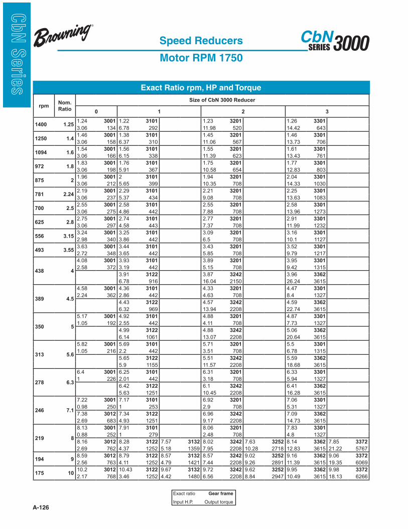
A-126
3000SERIESCbN
CbN
Serie
s Exact Ratio rpm, HP and Torque
Speed Reducers
Motor RPM 1750
Exact ratio Gear frame
Input H.P. Output torque
rpmNom.
Ratio
Size of CbN 3000 Reducer
0 1 2 3
1400 1.251.24 3001 1.22 3101 1.23 3201 1.26 3301
3.06 134 6.78 292 11.98 520 14.42 643
1250 1.41.46 3001 1.38 3101 1.45 3201 1.46 3301
3.06 158 6.37 310 11.06 567 13.73 706
1094 1.61.54 3001 1.56 3101 1.55 3201 1.61 3301
3.06 166 6.15 338 11.39 623 13.43 761
972 1.81.83 3001 1.76 3101 1.75 3201 1.77 3301
3.06 198 5.91 367 10.58 654 12.83 803
875 21.96 3001 2 3101 1.94 3201 2.04 3301
3.06 212 5.65 399 10.35 708 14.33 1030
781 2.242.19 3001 2.29 3101 2.21 3201 2.25 3301
3.06 237 5.37 434 9.08 708 13.63 1083
700 2.52.55 3001 2.58 3101 2.55 3201 2.58 3301
3.06 275 4.86 442 7.88 708 13.96 1273
625 2.82.75 3001 2.74 3101 2.77 3201 2.91 3301
3.06 297 4.58 443 7.37 708 11.99 1232
556 3.153.24 3001 3.25 3101 3.09 3201 3.16 3301
2.98 340 3.86 442 6.5 708 10.1 1127
493 3.553.63 3001 3.44 3101 3.43 3201 3.52 3301
2.72 348 3.65 442 5.85 708 9.79 1217
438 4
4.08 3001 3.93 3101 3.89 3201 3.95 3301
2.58 372 3.19 442 5.15 708 9.42 1315
3.91 3122 3.87 3242 3.96 3362
6.78 916 16.04 2150 26.24 3615
389 4.5
4.58 3001 4.36 3101 4.33 3201 4.47 3301
2.24 362 2.86 442 4.63 708 8.4 1327
4.43 3122 4.57 3242 4.59 3362
6.32 969 13.94 2208 22.74 3615
350 5
5.17 3001 4.92 3101 4.88 3201 4.87 3301
1.05 192 2.55 442 4.11 708 7.73 1327
4.99 3122 4.88 3242 5.06 3362
6.14 1061 13.07 2208 20.64 3615
313 5.6
5.82 3001 5.69 3101 5.71 3201 5.5 3301
1.05 216 2.2 442 3.51 708 6.78 1315
5.65 3122 5.51 3242 5.59 3362
5.9 1155 11.57 2208 18.68 3615
278 6.3
6.4 3001 6.25 3101 6.31 3201 6.33 3301
1 226 2.01 442 3.18 708 5.94 1327
6.42 3122 6.1 3242 6.41 3362
5.63 1251 10.45 2208 16.28 3615
246 7.1
7.22 3001 7.17 3101 6.92 3201 7.06 3301
0.98 250 1 253 2.9 708 5.31 1327
7.38 3012 7.34 3122 6.96 3242 7.09 3362
2.69 683 4.93 1251 9.17 2208 14.73 3615
219 8
8.13 3001 7.91 3101 8.06 3201 7.83 3301
0.88 252 1 279 2.48 708 4.8 1327
8.16 3012 8.28 3122 7.57 3132 8.02 3242 7.63 3252 8.14 3362 7.85 3372
2.69 762 4.37 1252 5.18 1359 7.95 2208 10.28 2718 12.83 3615 21.22 5767
194 98.59 3012 8.79 3122 8.57 3132 8.57 3242 9.02 3252 9.16 3362 9.06 3372
2.56 763 4.11 1252 4.79 1421 7.44 2208 9.26 2891 11.39 3615 19.35 6069
175 1010.2 3012 10.43 3122 9.67 3132 9.72 3242 9.62 3252 9.95 3362 9.98 3372
2.17 768 3.46 1252 4.42 1480 6.56 2208 8.84 2947 10.49 3615 18.13 6266

A-127
3000SERIESCbN
CbN
Serie
sExact Ratio rpm, HP and Torque
Speed Reducers
Motor RPM 1750 (Continued)
Exact ratio Gear frame
Input H.P. Output torque
If shaded, mechanical H.P. may exceed thermal H.P. limit.Refer to page A-144.
rpmNom.
Ratio
Size of CbN 3000 Reducer
4 5 6 7 8
1400 1.251.24 3401 1.28 3501
38.4 1679 61.53 2770
1250 1.41.38 3401 1.46 3501
41.22 2015 59.42 3062
1094 1.61.56 3401 1.6 3501
41.74 2292 57.18 3230
972 1.81.74 3401 1.79 3501
35.43 2171 55.44 3496
875 21.97 3401 2 3501
36.29 2521 52.88 3735
781 2.242.17 3401 2.25 3501
34.03 2610 50.13 3982
700 2.52.54 3401 2.44 3501
30.62 2745 48.17 4152
625 2.82.83 3401 2.77 3501
28.35 2836 46.17 4522
556 3.153.18 3401 3.07 3501 3.21 3602
25.76 2894 42.96 4655 120 13318
493 3.553.6 3401 3.55 3501 3.64 3602
22.84 2903 40.6 5088 120 15102
438 4
4.11 3401 3.88 3501
20 2903 38.16 5221
3.91 3482 4.07 3592 3.88 3602
38.77 5249 66.63 9371 120 16098
389 4.5
4.41 3401 4.35 3501
18.63 2903 33.97 5221
4.37 3482 4.66 3592 4.34 3602 4.39 3732
41.6 6299 66.63 10727 120 18006 120 18213
350 5
5.13 3401 4.85 3501
16.01 2903 30.49 5221
4.91 3482 5.1 3592 4.91 3602 4.91 3732
42.14 7168 66.63 11960 120 20371 120 20371
313 5.6
5.57 3401 5.5 3501
14.76 2903 26.29 5103
5.48 3482 5.7 3592 5.56 3602 5.63 3732 5.76 3842
35.76 6786 57.53 11350 120 23068 120 23358 190 37853
278 6.3
6.15 3401 6.31 3501
13.36 2903 23.43 5221
6.21 3482 6.38 3592 6.15 3602 6.21 3732 6.36 3842
36.63 7883 53.87 11903 120 25515 120 25764 190 41796
246 7.1
6.83 3401 6.87 3501
11.32 2730 21.54 5221
6.86 3482 7.18 3592 6.86 3602 7.04 3732 6.98 3842
34.35 8160 48.81 12133 120 25923 120 29208 190 45871
219 8
8.1 3401 8 3501
9.47 2708 18.48 5221
7.69 3482 7.92 3592 7.71 3602 7.99 3732 8.15 3842
38.77 10329 66.63 18252 101.9 27163 120 33149 190 53560
194 98.6 3482 9.07 3592 9.03 3602 9.09 3732 8.8 3842
38.41 11446 64.65 20305 84.4 26350 120 37713 190 57831
175 109.67 3482 9.94 3592 9.63 3602 10.3 3732 10 3842
35.65 11933 60.86 20956 93.4 31097 119.9 42697 190 65717

A-128
3000SERIESCbN
CbN
Serie
s Exact Ratio rpm, HP and Torque
Speed Reducers
Motor RPM 1750 (Continued)
Exact ratio Gear frame
Input H.P. Output torque
rpmNom.
Ratio
Size of CbN 3000 Reducer
0 1 2 3
156 11.210.92 3012 11.04 3122 10.94 3132 10.8 3242 10.88 3252 11.09 3362 11.03 3372
2.03 769 3.28 1252 4.07 1542 5.9 2208 8.18 3082 9.41 3615 16.56 6330
140 12.512.23 3012 12.61 3122 12.43 3132 12.27 3242 12.04 3252 12.45 3362 12.65 3372
1.82 772 2.87 1252 3.74 1609 5.2 2208 7.64 3186 8.39 3615 15.46 6774
125 1414.24 3012 14.08 3122 14.2 3132 13.65 3242 13.72 3252 14.09 3362 13.98 3372
1.57 776 2.57 1252 3.42 1681 4.67 2208 7.02 3335 7.41 3615 14.12 6839
109 1615.35 3012 15.79 3122 16.03 3132 15.36 3242 15.82 3252 15.33 3362 16.05 3372
1.46 777 2.29 1252 3.15 1750 4.15 2208 6.38 3492 6.81 3615 12.68 7052
97 1818.06 3012 18.28 3122 17.01 3132 18 3242 16.9 3252 17.33 3362 18.08 3372
1.25 781 1.98 1252 2.98 1753 3.54 2208 6.1 3571 6.03 3615 11.39 7132
88 2020.24 3012 20.07 3122 20.2 3132 19.87 3242 19.18 3252 19.95 3362 19.64 3372
1.12 783 1.8 1252 2.52 1762 3.21 2208 5.6 3719 5.23 3615 10.49 7132
78 22.422.76 3012 23.01 3122 21.36 3132 21.79 3242 21.31 3252 22.29 3362 21.89 3372
1 786 1 796 2.39 1765 2.93 2208 5.22 3850 4.68 3615 9.41 7132
70 2525.59 3012 25.39 3122 24.41 3132 25.44 3242 24.2 3252 24.68 3362 24.56 3372
0.89 787 1 878 2.09 1771 2.51 2208 4.72 3952 4.23 3615 8.39 7132
63 2828.85 3012 27.25 3132 26.93 3252 27.8 3372
0.79 789 1.88 1776 4.25 3964 7.41 7132
56 31.533.48 3012 30.55 3132 30.29 3252 32.32 3363 30.24 3372
0.7 791 1.68 1780 3.79 3977 5.4 5910 6.81 7132
49 35.535.73 3012 35.37 3132 35.51 3252 37.29 3363 34.18 3372
0.64 793 1.46 1786 3.25 3993 4.73 5965 6.03 7132
44 4040.32 3012 38.84 3132 39.2 3252 41.1 3363 39.36 3372
0.57 794 1.33 1790 2.95 4002 4.3 6010 5.23 7132
39 4545.36 3012 44.54 3132 42.98 3252 45.4 3363 43.98 3372
0.51 796 1 1540 2.69 4010 3.97 6070 4.68 7132
35 5049.16 3013 49.15 3132 50.19 3252 52.09 3363 48.68 3372
0.53 796 1 1699 2.32 4024 3.46 6100 4.23 7132
31 5655.04 3013 57.83 3133 55.7 3253 57.6 3363 57.57 3373
0.47 798 0.69 1351 2.13 4032 3.13 6100 3.77 7383
28 6364.07 3013 65.25 3133 64.2 3253 66.11 3363 66.1 3373
0.4 800 0.63 1406 1.85 4038 2.73 6100 3.36 7525
25 7169.09 3013 69.24 3133 68.61 3253 74.4 3363 74.44 3373
0.37 801 0.61 1434 1.73 4038 2.42 6100 3.02 7611
22 8081.29 3013 82.23 3133 77.86 3253 80.86 3363 80.87 3373
0.32 803 0.54 1519 1.53 4038 2.2 6100 2.78 7611
19 9091.08 3013 86.97 3133 86.48 3253 90.12 3363 90.1 3373
0.29 804 0.52 1547 1.37 4038 2 6100 2.5 7611
18 100102.43 3013 99.4 3133 98.24 3253 101.13 3363 101.13 3373
0.25 806 0.48 1618 1.21 4038 1.78 6100 2.22 7611
16 112115.16 3013 110.94 3133 109.3 3253 114.47 3363 114.47 3373
0.23 807 0.45 1678 1.09 4038 1.57 6100 1.96 7611
14 125129.81 3013 124.4 3133 122.96 3253 124.53 3363 124.53 3373
0.2 808 0.41 1744 0.97 4038 1.45 6100 1.8 7611
12.5 140146.18 3013 144.02 3133 144.13 3253 141 3363 140.74 3373
0.18 809 0.37 1804 0.82 4038 1.28 6100 1.6 7611
10.9 160160.8 3013 158.13 3133 159.1 3253 162.1 3363 162.06 3373
0.17 810 0.34 1804 0.75 4038 1.1 6100 1.39 7611
9.7 180181.46 3013 181.32 3133 174.46 3253 181 3363 181.09 3373
0.14 811 0.29 1804 0.68 4038 1 6100 1.24 7611
8.8 200204.14 3013 200.11 3133 203.72 3253 200.44 3363 200.44 3373
0.13 812 0.27 1804 0.58 4038 0.9 6100 1.12 7611
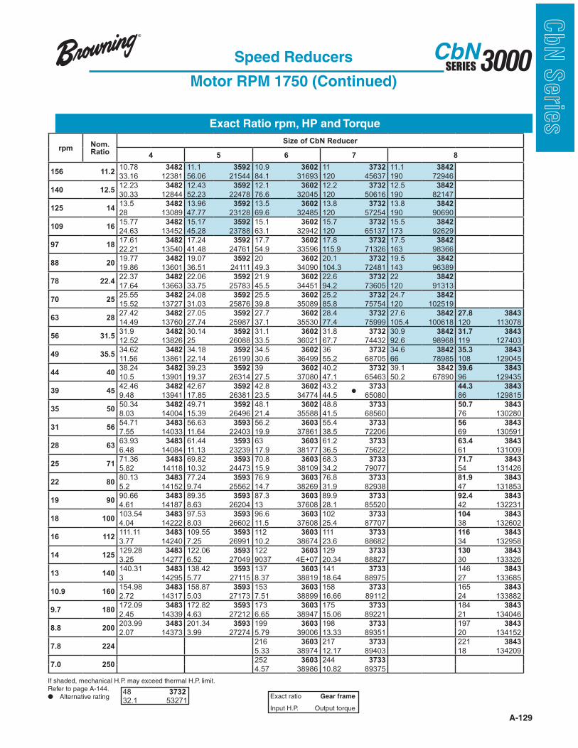
A-129
3000SERIESCbN
CbN
Serie
sExact Ratio rpm, HP and Torque
Speed Reducers
Motor RPM 1750 (Continued)
Exact ratio Gear frame
Input H.P. Output torque
48 373232.1 53271
rpmNom. Ratio
Size of CbN Reducer
4 5 6 7 8
156 11.210.78 3482 11.1 3592 10.9 3602 11 3732 11.1 3842
33.16 12381 56.06 21544 84.1 31693 120 45637 190 72946
140 12.512.23 3482 12.43 3592 12.1 3602 12.2 3732 12.5 3842
30.33 12844 52.23 22478 76.6 32045 120 50616 190 82147
125 1413.5 3482 13.96 3592 13.5 3602 13.8 3732 13.8 3842
28 13089 47.77 23128 69.6 32485 120 57254 190 90690
109 1615.77 3482 15.17 3592 15.1 3602 15.7 3732 15.5 3842
24.63 13452 45.28 23788 63.1 32942 120 65137 173 92629
97 1817.61 3482 17.24 3592 17.7 3602 17.8 3732 17.5 3842
22.21 13540 41.48 24761 54.9 33596 115.9 71326 163 98366
88 2019.77 3482 19.07 3592 20 3602 20.1 3732 19.5 3842
19.86 13601 36.51 24111 49.3 34090 104.3 72481 143 96389
78 22.422.37 3482 22.06 3592 21.9 3602 22.6 3732 22 3842
17.64 13663 33.75 25783 45.5 34451 94.2 73605 120 91313
70 2525.55 3482 24.08 3592 25.5 3602 25.2 3732 24.7 3842
15.52 13727 31.03 25876 39.8 35089 85.8 75754 120 102519
63 2827.42 3482 27.05 3592 27.7 3602 28.4 3732 27.6 3842 27.8 3843
14.49 13760 27.74 25987 37.1 35530 77.4 75999 105.4 100618 120 113078
56 31.531.9 3482 30.14 3592 31.1 3602 31.8 3732 30.9 3842 31.7 3843
12.52 13826 25 26088 33.5 36021 67.7 74432 92.6 98968 119 127403
49 35.534.62 3482 34.18 3592 34.5 3602 36 3732 34.6 3842 35.3 3843
11.56 13861 22.14 26199 30.6 36499 55.2 68705 66 78985 108 129045
44 4038.24 3482 39.23 3592 39 3602 40.2 3732 39.1 3842 39.6 3843
10.5 13901 19.37 26314 27.5 37080 47.1 65463 50.2 67890 96 129435
39 4542.46 3482 42.67 3592 42.8 3602 43.2 3733 44.3 3843
9.48 13941 17.85 26381 23.5 34774 44.5 65080 86 129815
35 5050.34 3482 49.71 3592 48.1 3602 48.8 3733 50.7 3843
8.03 14004 15.39 26496 21.4 35588 41.5 68560 76 130280
31 5654.71 3483 56.63 3593 56.2 3603 55.4 3733 56 3843
7.55 14033 11.64 22403 19.9 37861 38.5 72206 69 130591
28 6363.93 3483 61.44 3593 63 3603 61.2 3733 63.4 3843
6.48 14084 11.13 23239 17.9 38177 36.5 75622 61 131009
25 7171.36 3483 69.82 3593 70.8 3603 68.3 3733 71.7 3843
5.82 14118 10.32 24473 15.9 38109 34.2 79077 54 131426
22 8080.13 3483 77.24 3593 76.9 3603 76.8 3733 81.9 3843
5.2 14152 9.74 25562 14.7 38269 31.9 82938 47 131853
19 9090.66 3483 89.35 3593 87.3 3603 89.9 3733 92.4 3843
4.61 14187 8.63 26204 13 37608 28.1 85520 42 132231
18 100103.54 3483 97.53 3593 96.6 3603 102 3733 104 3843
4.04 14222 8.03 26602 11.5 37608 25.4 87707 38 132602
16 112111.11 3483 109.55 3593 112 3603 111 3733 116 3843
3.77 14240 7.25 26991 10.2 38674 23.6 88682 34 132958
14 125129.28 3483 122.06 3593 122 3603 129 3733 130 3843
3.25 14277 6.52 27049 9037 4E+07 20.34 88827 30 133326
13 140140.31 3483 138.42 3593 137 3603 141 3733 146 3843
3 14295 5.77 27115 8.37 38819 18.64 88975 27 133685
10.9 160154.98 3483 158.87 3593 153 3603 158 3733 165 3843
2.72 14317 5.03 27173 7.51 38899 16.66 89112 24 133882
9.7 180172.09 3483 172.82 3593 173 3603 175 3733 184 3843
2.45 14339 4.63 27212 6.65 38947 15.06 89221 21 134046
8.8 200203.99 3483 201.34 3593 199 3603 198 3733 197 3843
2.07 14373 3.99 27274 5.79 39006 13.33 89351 20 134152
7.8 224216 3603 217 3733 221 3843
5.33 38974 12.17 89403 18 134209
7.0 250252 3603 244 3733
4.57 38986 10.82 89375
If shaded, mechanical H.P. may exceed thermal H.P. limit.Refer to page A-144.● Alternative rating
●

A-130
3000SERIESCbN
CbN
Serie
s Exact Ratio rpm, HP and Torque
Speed Reducers
Motor RPM 1450
Exact ratio Gear frame
Input H.P. Output torque
rpmNom.
Ratio
Size of CbN 3000 Reducer
0 1 2 3
1160 1.251.24 3001 1.22 3101 1.23 3201 1.26 3301
2.54 134 5.62 292 10.54 552 12.7 684
1036 1.41.46 3001 1.38 3101 1.45 3201 1.46 3301
2.54 158 5.61 330 9.74 602 11.82 750
906 1.61.54 3001 1.56 3101 1.55 3201 1.61 3301
2.54 167 5.41 359 10.03 661 11.29 809
806 1.81.83 3001 1.76 3101 1.75 3201 1.77 3301
2.54 198 5.2 390 9.31 694 12.63 854
725 21.96 3001 2 3101 1.94 3201 2.04 3301
2.54 212 4.54 424 8.57 708 12 1095
647 2.242.19 3001 2.29 3101 2.21 3201 2.25 3301
2.54 237 4.54 442 7.52 708 12 1151
580 2.52.55 3001 2.58 3101 2.55 3201 2.58 3301
2.54 276 4.03 442 6.53 708 12.06 1327
518 2.82.75 3001 2.74 3101 2.77 3201 2.91 3301
2.54 298 3.79 443 6.11 708 10.56 1309
460 3.153.24 3001 3.25 3101 3.09 3201 3.16 3301
2.49 343 3.19 442 5.38 708 8.89 1198
408 3.553.63 3001 3.44 3101 3.43 3201 3.52 3301
2.27 351 3.02 442 4.85 708 8.62 1293
363 4
4.08 3001 3.93 3101 3.89 3201 3.95 3301
2.16 375 2.64 442 4.27 708 7.88 1327
3.91 3122 3.87 3242 3.96 3362
5.62 919 13.65 2150 21.74 3615
322 4.5
4.58 3001 4.36 3101 4.33 3201 4.47 3301
1.87 365 2.37 442 3.83 708 6.96 1327
4.43 3122 4.57 3242 4.59 3362
5.56 1030 11.55 2208 18.85 3615
290 5
5.17 3001 4.92 3101 4.88 3201 4.87 3301
0.84 178 2.11 442 3.41 708 6.4 1327
4.99 3122 4.88 3242 5.06 3362
5.4 1128 10.83 2208 17.1 3615
259 5.6
5.82 3001 5.69 3101 5.71 3201 5.5 3301
0.84 201 1.82 442 2.91 708 5.62 1318
5.65 3122 5.51 3242 5.59 3362
5.2 1228 9.58 2208 15.48 3615
230 6.3
6.4 3001 6.25 3101 6.31 3201 6.33 3301
0.81 221 1.66 442 2.63 708 4.92 1327
6.42 3122 6.1 3242 6.41 3362
4.66 1252 8.66 2208 13.49 3615
204 7.1
7.22 3001 7.17 3101 6.92 3201 7.06 3301
0.81 249 0.81 247 2.4 708 4.4 1327
7.38 3012 7.34 3122 6.96 3242 7.09 3362
2.23 683 4.08 1252 7.59 2208 12.2 3615
181 8
8.13 3001 7.91 3101 8.06 3201 7.83 3301
0.81 254 0.81 273 2.06 708 3.98 1327
8.16 3012 8.28 3122 7.57 3132 8.02 3242 7.63 3252 8.14 3362 7.85 3372
2.25 766 3.62 1252 4.53 1435 6.59 2208 9 2871 10.63 3615 18.57 6091
161 98.59 3012 8.79 3122 8.57 3132 8.57 3242 9.02 3252 9.16 3362 9.06 3372
2.14 768 3.41 1252 4.19 1501 6.17 2208 8.1 3054 9.44 3615 16.94 6410
145 1010.2 3012 10.43 3122 9.67 3132 9.72 3242 9.62 3252 9.95 3362 9.98 3372
1.81 772 2.87 1252 3.87 1564 5.43 2208 7.74 3113 8.69 3615 15.87 6618
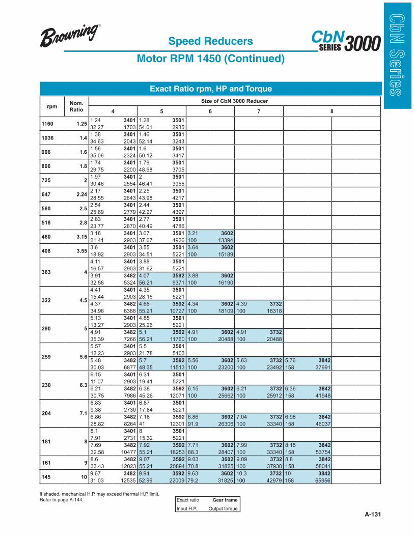
A-131
3000SERIESCbN
CbN
Serie
sExact Ratio rpm, HP and Torque
Speed Reducers
Motor RPM 1450 (Continued)
Exact ratio Gear frame
Input H.P. Output torque
rpmNom.
Ratio
Size of CbN 3000 Reducer
4 5 6 7 8
1160 1.251.24 3401 1.28 3501
32.27 1703 54.01 2935
1036 1.41.38 3401 1.46 3501
34.63 2043 52.14 3243
906 1.61.56 3401 1.6 3501
35.06 2324 50.12 3417
806 1.81.74 3401 1.79 3501
29.75 2200 48.68 3705
725 21.97 3401 2 3501
30.46 2554 46.41 3955
647 2.242.17 3401 2.25 3501
28.55 2643 43.98 4217
580 2.52.54 3401 2.44 3501
25.69 2779 42.27 4397
518 2.82.83 3401 2.77 3501
23.77 2870 40.49 4786
460 3.153.18 3401 3.07 3501 3.21 3602
21.41 2903 37.67 4926 100 13394
408 3.553.6 3401 3.55 3501 3.64 3602
18.92 2903 34.51 5221 100 15189
363 4
4.11 3401 3.88 3501
16.57 2903 31.62 5221
3.91 3482 4.07 3592 3.88 3602
32.58 5324 56.21 9371 100 16190
322 4.5
4.41 3401 4.35 3501
15.44 2903 28.15 5221
4.37 3482 4.66 3592 4.34 3602 4.39 3732
34.96 6388 55.21 10727 100 18109 100 18318
290 5
5.13 3401 4.85 3501
13.27 2903 25.26 5221
4.91 3482 5.1 3592 4.91 3602 4.91 3732
35.39 7266 56.21 11760 100 20488 100 20488
259 5.6
5.57 3401 5.5 3501
12.23 2903 21.78 5103
5.48 3482 5.7 3592 5.56 3602 5.63 3732 5.76 3842
30.03 6877 48.35 11513 100 23200 100 23492 158 37991
230 6.3
6.15 3401 6.31 3501
11.07 2903 19.41 5221
6.21 3482 6.38 3592 6.15 3602 6.21 3732 6.36 3842
30.75 7986 45.26 12071 100 25662 100 25912 158 41948
204 7.1
6.83 3401 6.87 3501
9.38 2730 17.84 5221
6.86 3482 7.18 3592 6.86 3602 7.04 3732 6.98 3842
28.82 8264 41 12301 91.9 26306 100 33340 158 46037
181 8
8.1 3401 8 3501
7.91 2731 15.32 5221
7.69 3482 7.92 3592 7.71 3602 7.99 3732 8.15 3842
32.58 10477 55.21 18253 88.3 28407 100 33340 158 53754
161 98.6 3482 9.07 3592 9.03 3602 9.09 3732 8.8 3842
33.43 12023 55.21 20894 70.8 31825 100 37930 158 58041
If shaded, mechanical H.P. may exceed thermal H.P. limit.Refer to page A-144.
145 109.67 3482 9.94 3592 9.63 3602 10.3 3732 10 3842
31.03 12535 52.96 22009 79.2 31825 100 42979 158 65956
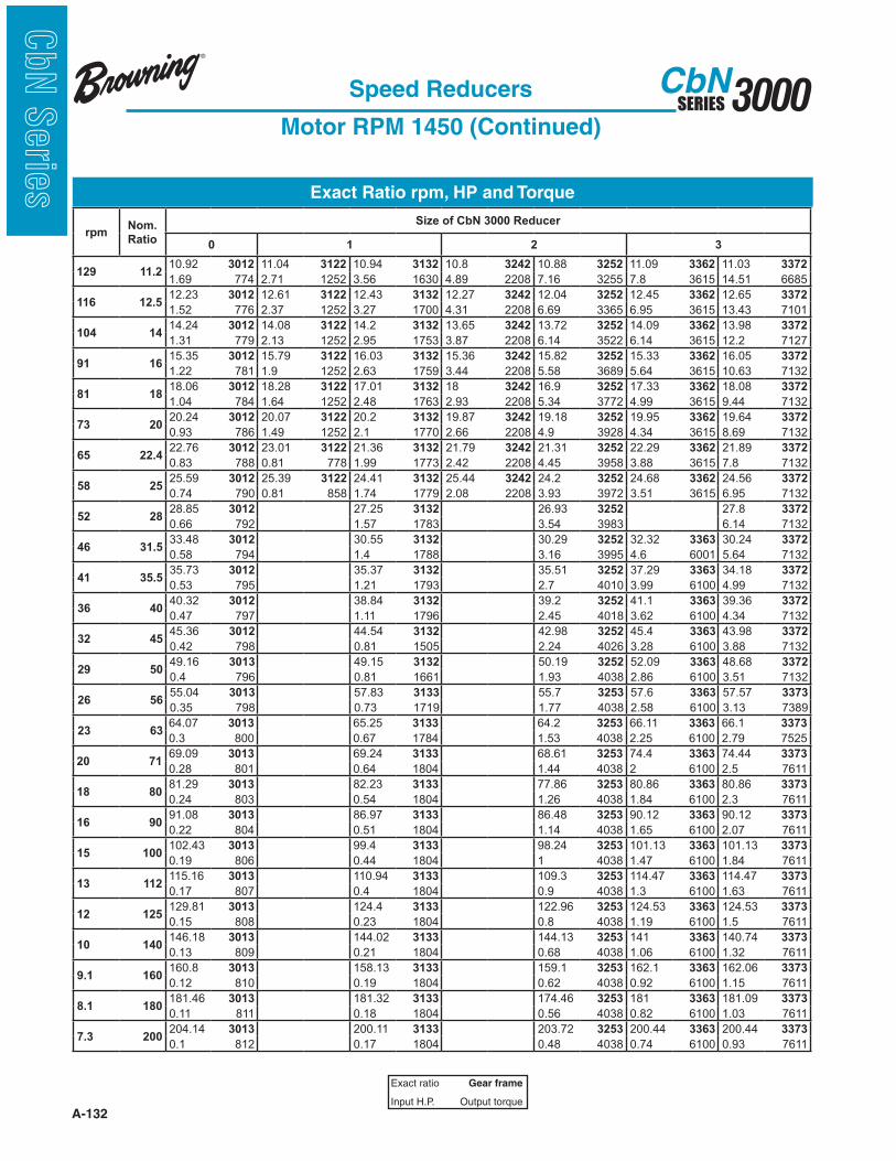
A-132
3000SERIESCbN
CbN
Serie
s Exact Ratio rpm, HP and Torque
Speed Reducers
Motor RPM 1450 (Continued)
Exact ratio Gear frame
Input H.P. Output torque
rpmNom.
Ratio
Size of CbN 3000 Reducer
0 1 2 3
129 11.210.92 3012 11.04 3122 10.94 3132 10.8 3242 10.88 3252 11.09 3362 11.03 3372
1.69 774 2.71 1252 3.56 1630 4.89 2208 7.16 3255 7.8 3615 14.51 6685
116 12.512.23 3012 12.61 3122 12.43 3132 12.27 3242 12.04 3252 12.45 3362 12.65 3372
1.52 776 2.37 1252 3.27 1700 4.31 2208 6.69 3365 6.95 3615 13.43 7101
104 1414.24 3012 14.08 3122 14.2 3132 13.65 3242 13.72 3252 14.09 3362 13.98 3372
1.31 779 2.13 1252 2.95 1753 3.87 2208 6.14 3522 6.14 3615 12.2 7127
91 1615.35 3012 15.79 3122 16.03 3132 15.36 3242 15.82 3252 15.33 3362 16.05 3372
1.22 781 1.9 1252 2.63 1759 3.44 2208 5.58 3689 5.64 3615 10.63 7132
81 1818.06 3012 18.28 3122 17.01 3132 18 3242 16.9 3252 17.33 3362 18.08 3372
1.04 784 1.64 1252 2.48 1763 2.93 2208 5.34 3772 4.99 3615 9.44 7132
73 2020.24 3012 20.07 3122 20.2 3132 19.87 3242 19.18 3252 19.95 3362 19.64 3372
0.93 786 1.49 1252 2.1 1770 2.66 2208 4.9 3928 4.34 3615 8.69 7132
65 22.422.76 3012 23.01 3122 21.36 3132 21.79 3242 21.31 3252 22.29 3362 21.89 3372
0.83 788 0.81 778 1.99 1773 2.42 2208 4.45 3958 3.88 3615 7.8 7132
58 2525.59 3012 25.39 3122 24.41 3132 25.44 3242 24.2 3252 24.68 3362 24.56 3372
0.74 790 0.81 858 1.74 1779 2.08 2208 3.93 3972 3.51 3615 6.95 7132
52 2828.85 3012 27.25 3132 26.93 3252 27.8 3372
0.66 792 1.57 1783 3.54 3983 6.14 7132
46 31.533.48 3012 30.55 3132 30.29 3252 32.32 3363 30.24 3372
0.58 794 1.4 1788 3.16 3995 4.6 6001 5.64 7132
41 35.535.73 3012 35.37 3132 35.51 3252 37.29 3363 34.18 3372
0.53 795 1.21 1793 2.7 4010 3.99 6100 4.99 7132
36 4040.32 3012 38.84 3132 39.2 3252 41.1 3363 39.36 3372
0.47 797 1.11 1796 2.45 4018 3.62 6100 4.34 7132
32 4545.36 3012 44.54 3132 42.98 3252 45.4 3363 43.98 3372
0.42 798 0.81 1505 2.24 4026 3.28 6100 3.88 7132
29 5049.16 3013 49.15 3132 50.19 3252 52.09 3363 48.68 3372
0.4 796 0.81 1661 1.93 4038 2.86 6100 3.51 7132
26 5655.04 3013 57.83 3133 55.7 3253 57.6 3363 57.57 3373
0.35 798 0.73 1719 1.77 4038 2.58 6100 3.13 7389
23 6364.07 3013 65.25 3133 64.2 3253 66.11 3363 66.1 3373
0.3 800 0.67 1784 1.53 4038 2.25 6100 2.79 7525
20 7169.09 3013 69.24 3133 68.61 3253 74.4 3363 74.44 3373
0.28 801 0.64 1804 1.44 4038 2 6100 2.5 7611
18 8081.29 3013 82.23 3133 77.86 3253 80.86 3363 80.86 3373
0.24 803 0.54 1804 1.26 4038 1.84 6100 2.3 7611
16 9091.08 3013 86.97 3133 86.48 3253 90.12 3363 90.12 3373
0.22 804 0.51 1804 1.14 4038 1.65 6100 2.07 7611
15 100102.43 3013 99.4 3133 98.24 3253 101.13 3363 101.13 3373
0.19 806 0.44 1804 1 4038 1.47 6100 1.84 7611
13 112115.16 3013 110.94 3133 109.3 3253 114.47 3363 114.47 3373
0.17 807 0.4 1804 0.9 4038 1.3 6100 1.63 7611
12 125129.81 3013 124.4 3133 122.96 3253 124.53 3363 124.53 3373
0.15 808 0.23 1804 0.8 4038 1.19 6100 1.5 7611
10 140146.18 3013 144.02 3133 144.13 3253 141 3363 140.74 3373
0.13 809 0.21 1804 0.68 4038 1.06 6100 1.32 7611
9.1 160160.8 3013 158.13 3133 159.1 3253 162.1 3363 162.06 3373
0.12 810 0.19 1804 0.62 4038 0.92 6100 1.15 7611
8.1 180181.46 3013 181.32 3133 174.46 3253 181 3363 181.09 3373
0.11 811 0.18 1804 0.56 4038 0.82 6100 1.03 7611
7.3 200204.14 3013 200.11 3133 203.72 3253 200.44 3363 200.44 3373
0.1 812 0.17 1804 0.48 4038 0.74 6100 0.93 7611
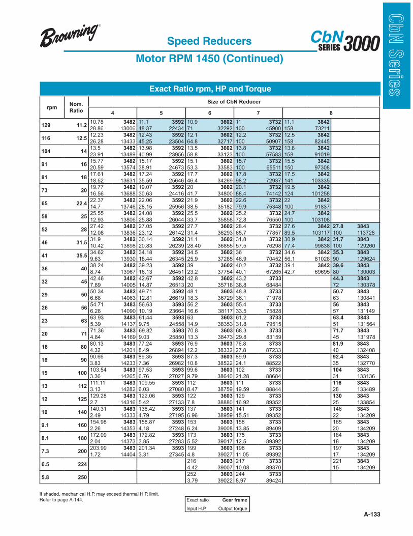
A-133
3000SERIESCbN
CbN
Serie
sExact Ratio rpm, HP and Torque
Speed Reducers
Motor RPM 1450 (Continued)
Exact ratio Gear frame
Input H.P. Output torque
rpmNom.
Ratio
Size of CbN Reducer
4 5 6 7 8
129 11.210.78 3482 11.1 3592 10.9 3602 11 3732 11.1 3842
28.86 13006 48.37 22434 71 32292 100 45900 158 73211
116 12.512.23 3482 12.43 3592 12.1 3602 12.2 3732 12.5 3842
26.28 13433 45.25 23504 64.8 32717 100 50907 158 82445
104 1413.5 3482 13.98 3592 13.5 3602 13.8 3732 13.8 3842
23.91 13489 40.99 23956 58.8 33123 100 57583 158 91019
91 1615.77 3482 15.17 3592 15.1 3602 15.7 3732 15.5 3842
20.59 13574 38.91 24673 53.3 33583 100 65511 150 97308
81 1817.61 3482 17.24 3592 17.7 3602 17.8 3732 17.5 3842
18.52 13631 35.59 25646 46.4 34269 98.2 72937 141 103335
73 2019.77 3482 19.07 3592 20 3602 20.1 3732 19.5 3842
16.56 13688 30.63 24416 41.7 34800 88.4 74142 124 101258
65 22.422.37 3482 22.06 3592 21.9 3602 22.6 3732 22 3842
14.7 13746 28.15 25956 38.5 35182 79.9 75348 100 91837
58 2525.55 3482 24.08 3592 25.5 3602 25.2 3732 24.7 3842
12.93 13806 25.88 26044 33.7 35858 72.8 76550 100 103108
52 2827.42 3482 27.05 3592 27.7 3602 28.4 3732 27.6 3842 27.8 3843
12.08 13836 23.12 26142 31.4 36293 65.7 77857 89.5 103117 100 113728
46 31.531.9 3482 30.14 3592 31.1 3602 31.8 3732 30.9 3842 31.7 3843
10.42 13898 20.83 26239 28.40 36855 57.5 76298 77.4 99838 100 129260
41 35.534.62 3482 34.18 3592 34.5 3602 36 3732 34.6 3842 35.3 3843
9.63 13930 18.44 26345 25.9 37285 46.9 70452 56.1 81028 90 129624
36 4038.24 3482 39.23 3592 39 3602 40.2 3732 39.1 3842 39.6 3843
8.74 13967 16.13 26451 23.2 37754 40.1 67265 42.7 69695 80 130003
32 4542.46 3482 42.67 3592 42.8 3602 43.2 3733 44.3 3843
7.89 14005 14.87 26513 20 35718 38.8 68484 72 130378
29 5050.34 3482 49.71 3592 48.1 3603 48.8 3733 50.7 3843
6.68 14063 12.81 26619 18.3 36729 36.1 71978 63 130841
26 5654.71 3483 56.63 3593 56.2 3603 55.4 3733 56 3843
6.28 14090 10.19 23664 16.6 38117 33.5 75828 57 131149
23 6363.93 3483 61.44 3593 63 3603 61.2 3733 63.4 3843
5.39 14137 9.75 24558 14.9 38353 31.8 79515 51 131564
20 7171.36 3483 69.82 3593 70.8 3603 68.3 3733 71.7 3843
4.84 14169 9.03 25850 13.3 38473 29.8 83159 45 131978
18 8080.13 3483 77.24 3593 76.9 3603 76.8 3733 81.9 3843
4.32 14201 8.49 26894 12.2 38332 27.8 87233 40 132408
16 9090.66 3483 89.35 3593 87.3 3603 89.9 3733 92.4 3843
3.83 14233 7.36 26982 10.8 38522 24.1 88522 35 132770
15 100103.54 3483 97.53 3593 99.6 3603 102 3733 104 3843
3.36 14265 6.76 27027 9.79 38640 21.28 88684 31 133136
13 112111.11 3483 109.55 3593 112 3603 111 3733 116 3843
3.13 14282 6.03 27080 8.47 38759 19.59 88844 28 133489
12 125129.28 3483 122.06 3593 122 3603 129 3733 130 3843
2.7 14316 5.42 27133 7.8 38880 16.92 89352 25 133854
10 140140.31 3483 138.42 3593 137 3603 141 3733 146 3843
2.49 14333 4.79 27195 6.96 38959 15.51 89352 22 134209
9.1 160154.98 3483 158.87 3593 153 3603 158 3733 165 3843
2.26 14353 4.18 27248 6.24 39008 13.85 89409 20 134209
8.1 180172.09 3483 172.82 3593 173 3603 175 3733 184 3843
2.04 14373 3.85 27283 5.52 39017 12.5 89392 18 134209
7.3 200203.99 3483 201.34 3593 199 3603 198 3733 197 3843
1.72 14404 3.31 27345 4.8 39027 11.05 89392 17 134209
6.5 224216 3603 217 3733 221 3843
4.42 39007 10.08 89370 15 134209
5.8 250252 3603 244 3733
3.79 39022 8.97 89424
If shaded, mechanical H.P. may exceed thermal H.P. limit.Refer to page A-144.
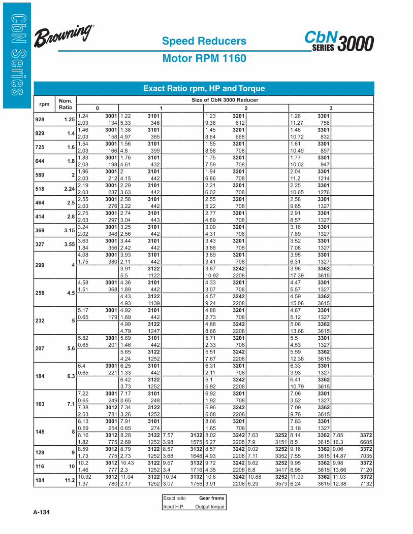
A-134
3000SERIESCbN
CbN
Serie
s Exact Ratio rpm, HP and Torque
Speed Reducers
Motor RPM 1160
Exact ratio Gear frame
Input H.P. Output torque
rpmNom.
Ratio
Size of CbN 3000 Reducer
0 1 2 3
928 1.251.24 3001 1.22 3101 1.23 3201 1.26 3301
2.03 134 5.33 346 9.36 612 11.27 758
829 1.41.46 3001 1.38 3101 1.45 3201 1.46 3301
2.03 158 4.97 365 8.64 668 10.72 832
725 1.61.54 3001 1.56 3101 1.55 3201 1.61 3301
2.03 166 4.8 399 8.58 708 10.49 897
644 1.81.83 3001 1.76 3101 1.75 3201 1.77 3301
2.03 198 4.61 432 7.59 708 10.02 947
580 21.96 3001 2 3101 1.94 3201 2.04 3301
2.03 212 4.15 442 6.86 708 11.2 1214
518 2.242.19 3001 2.29 3101 2.21 3201 2.25 3301
2.03 237 3.63 442 6.02 708 10.65 1276
464 2.52.55 3001 2.58 3101 2.55 3201 2.58 3301
2.03 276 3.22 442 5.22 708 9.65 1327
414 2.82.75 3001 2.74 3101 2.77 3201 2.91 3301
2.03 297 3.04 443 4.89 708 8.57 1327
368 3.153.24 3001 3.25 3101 3.09 3201 3.16 3301
2.02 348 2.56 442 4.31 708 7.89 1327
327 3.553.63 3001 3.44 3101 3.43 3201 3.52 3301
1.84 356 2.42 442 3.88 708 7.08 1327
290 4
4.08 3001 3.93 3101 3.89 3201 3.95 3301
1.75 380 2.11 442 3.41 708 6.31 1327
3.91 3122 3.87 3242 3.96 3362
5.5 1122 10.92 2208 17.39 3615
258 4.5
4.58 3001 4.36 3101 4.33 3201 4.47 3301
1.51 368 1.89 442 3.07 708 5.57 1327
4.43 3122 4.57 3242 4.59 3362
4.93 1139 9.24 2208 15.08 3615
232 5
5.17 3001 4.92 3101 4.88 3201 4.87 3301
0.65 179 1.69 442 2.73 708 5.12 1327
4.99 3122 4.88 3242 5.06 3362
4.79 1247 8.66 2208 13.68 3615
207 5.6
5.82 3001 5.69 3101 5.71 3201 5.5 3301
0.65 201 1.46 442 2.33 708 4.53 1327
5.65 3122 5.51 3242 5.59 3362
4.24 1252 7.67 2208 12.38 3615
184 6.3
6.4 3001 6.25 3101 6.31 3201 6.33 3301
0.65 221 1.33 442 2.11 708 3.93 1327
6.42 3122 6.1 3242 6.41 3362
3.73 1252 6.92 2208 10.79 3615
163 7.1
7.22 3001 7.17 3101 6.92 3201 7.06 3301
0.65 249 0.65 248 1.92 708 3.52 1327
7.38 3012 7.34 3122 6.96 3242 7.09 3362
2.03 781 3.26 1252 6.08 2208 9.76 3615
145 8
8.13 3001 7.91 3101 8.06 3201 7.83 3301
0.59 254 0.65 274 1.65 708 3.18 1327
8.16 3012 8.28 3122 7.57 3132 8.02 3242 7.63 3252 8.14 3362 7.85 3372
1.82 775 2.89 1252 3.98 1575 5.27 2208 7.9 3151 8.5 3615 16.3 6685
129 98.59 3012 8.79 3122 8.57 3132 8.57 3242 9.02 3252 9.16 3362 9.06 3372
1.73 775 2.73 1252 3.68 1648 4.93 2208 7.11 3352 7.55 3615 14.87 7035
116 1010.2 3012 10.43 3122 9.67 3132 9.72 3242 9.62 3252 9.95 3362 9.98 3372
1.46 777 2.3 1252 3.4 1716 4.35 2208 6.8 3417 6.95 3615 13.66 7120
104 11.210.92 3012 11.04 3122 10.94 3132 10.8 3242 10.88 3252 11.09 3362 11.03 3372
1.37 780 2.17 1252 3.07 1756 3.91 2208 6.29 3573 6.24 3615 12.38 7132
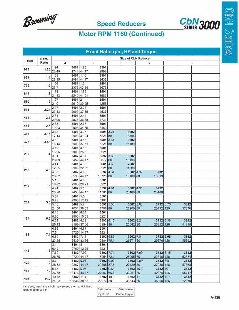
A-135
3000SERIESCbN
CbN
Serie
sExact Ratio rpm, HP and Torque
Speed Reducers
Motor RPM 1160 (Continued)
Exact ratio Gear frame
Input H.P. Output torque
rpmNom.
Ratio
Size of CbN Reducer
4 5 6 7 8
928 1.251.24 3401 1.26 3501
26.45 1744 44.17 2999
829 1.41.38 3401 1.46 3501
28.35 2091 44.17 3432
725 1.61.56 3401 1.6 3501
28.7 2378 43.14 3677
644 1.81.74 3401 1.79 3501
24.33 2249 41.91 3986
580 21.97 3401 2 3501
24.9 2610 39.95 4256
518 2.242.17 3401 2.25 3501
23.33 2699 37.85 4537
464 2.52.54 3401 2.44 3501
20.96 2835 36.38 4731
414 2.82.83 3401 2.77 3501
19.23 2903 34.85 5150
368 3.153.18 3401 3.07 3501 3.21 3602
17.13 2903 31.94 5221 80 13394
327 3.553.6 3401 3.55 3501 3.64 3602
15.14 2903 27.61 5221 80 15189
290 4
4.11 3401 3.88 3501
13.26 2903 25.3 5221
3.91 3482 4.07 3592 3.88 3602
26.69 5452 44.17 9372 80 16190
258 4.5
4.41 3401 4.35 3601 4.6 2602
12.35 2903 22.52 5221 80 11980
4.37 3482 4.66 3592 4.34 3602 4.39 3732
28.62 6538 44.17 10728 80 18109 80 18318
232 5
5.13 3401 4.85 3501
10.62 2903 20.21 5221
4.91 3482 5.1 3592 4.91 3602 4.91 3732
28.96 7433 44.17 11761 80 20488 80 20488
207 5.6
5.57 3401 5.5 3501
9.78 2903 17.42 5101
5.48 3482 5.7 3592 5.56 3602 5.63 3732 5.76 3842
24.56 7031 39.63 11796 80 23200 80 23492 126 37870
184 6.3
6.15 3401 6.31 3501
8.86 2903 15.53 5221
6.21 3482 6.38 3592 6.15 3602 6.21 3732 6.36 3842
25.13 8159 37.06 12354 80 25662 80 25912 126 41815
163 7.1
6.83 3401 6.87 3501
7.5 2729 14.27 5221
6.86 3482 7.18 3592 6.86 3602 7.04 3732 6.98 3842
23.55 8439 33.56 12584 75.1 26871 80 29376 126 45892
145 8
8.1 3401 8 3501
6.42 2769 12.25 5221
7.69 3482 7.92 3592 7.71 3602 7.99 3732 8.15 3842
26.69 10729 44.17 18254 72.1 28995 80 33340 126 53584
129 98.6 3482 9.07 3592 9.03 3602 9.09 3732 8.8 3842
28.62 12867 44.17 20895 57.6 27129 80 37930 126 57858
116 109.67 3482 9.94 3592 9.63 3602 10.3 3732 10 3842
26.68 13476 44.17 22907 65.8 33051 80 42979 126 65747
104 11.210.78 3482 11.1 3592 10.9 3602 11 3732 11.1 3842
24.03 13536 39.63 22973 59 33543 80 45900 126 72979
If shaded, mechanical H.P. may exceed thermal H.P. limit.Refer to page A-144.
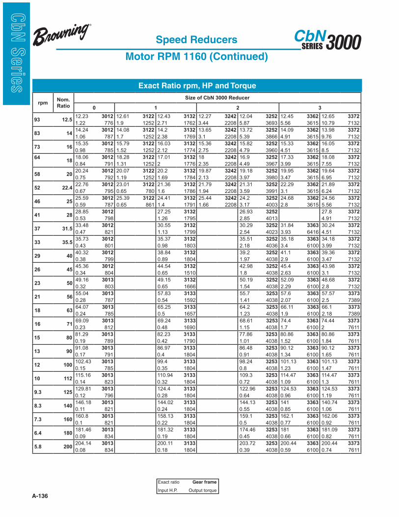
A-136
3000SERIESCbN
CbN
Serie
s Exact Ratio rpm, HP and Torque
Speed Reducers
Motor RPM 1160 (Continued)
Exact ratio Gear frame
Input H.P. Output torque
rpmNom.
Ratio
Size of CbN 3000 Reducer
0 1 2 3
93 12.512.23 3012 12.61 3122 12.43 3132 12.27 3242 12.04 3252 12.45 3362 12.65 3372
1.22 776 1.9 1252 2.71 1762 3.44 2208 5.87 3693 5.56 3615 10.79 7132
83 1414.24 3012 14.08 3122 14.2 3132 13.65 3242 13.72 3252 14.09 3362 13.98 3372
1.06 787 1.7 1252 2.38 1769 3.1 2208 5.39 3866 4.91 3615 9.76 7132
73 1615.35 3012 15.79 3122 16.03 3132 15.36 3242 15.82 3252 15.33 3362 16.05 3372
0.98 785 1.52 1252 2.12 1774 2.75 2208 4.79 3960 4.51 3615 8.5 7132
64
18
18.06 3012 18.28 3122 17.01 3132 18 3242 16.9 3252 17.33 3362 18.08 3372
0.84 791 1.31 1252 2 1776 2.35 2208 4.49 3967 3.99 3615 7.55 7132
58 2020.24 3012 20.07 3122 20.2 3132 19.87 3242 19.18 3252 19.95 3362 19.64 3372
0.75 792 1.19 1252 1.69 1784 2.13 2208 3.97 3980 3.47 3615 6.95 7132
52 22.422.76 3012 23.01 3122 21.36 3132 21.79 3242 21.31 3252 22.29 3362 21.89 3372
0.67 795 0.65 780 1.6 1786 1.94 2208 3.59 3991 3.1 3615 6.24 7132
46 2525.59 3012 25.39 3122 24.41 3132 25.44 3242 24.2 3252 24.68 3362 24.56 3372
0.59 787 0.65 861 1.4 1791 1.66 2208 3.17 4003 2.8 3615 5.56 7132
41 2828.85 3012 27.25 3132 26.93 3252 27.8 3372
0.53 798 1.26 1795 2.85 4013 4.91 7132
37 31.533.48 3012 30.55 3132 30.29 3252 31.84 3363 30.24 3372
0.47 821 1.13 1799 2.54 4023 3.93 6416 4.51 7132
33 35.535.73 3012 35.37 3132 35.51 3252 35.18 3363 34.18 3372
0.43 801 0.98 1803 2.18 4036 3.4 6100 3.99 7132
29 4040.32 3012 38.84 3132 39.2 3252 41.1 3363 39.36 3372
0.38 799 0.89 1804 1.97 4038 2.9 6100 3.47 7132
26 4545.36 3012 44.54 3132 42.98 3252 45.4 3363 43.98 3372
0.34 804 0.65 1510 1.8 4038 2.63 6100 3.1 7132
23 5049.16 3013 49.15 3132 50.19 3252 52.09 3363 48.68 3372
0.32 803 0.65 1666 1.54 4038 2.29 6100 2.8 7132
21 5655.04 3013 57.83 3133 55.7 3253 57.6 3363 57.57 3373
0.28 787 0.54 1592 1.41 4038 2.07 6100 2.5 7389
18 6364.07 3013 65.25 3133 64.2 3253 66.11 3363 66.1 3373
0.24 785 0.5 1657 1.23 4038 1.9 6100 2.18 7389
16 7169.09 3013 69.24 3133 68.61 3253 74.4 3363 74.44 3373
0.23 812 0.48 1690 1.15 4038 1.7 6100 2 7611
15 8081.29 3013 82.23 3133 77.86 3253 80.86 3363 80.86 3373
0.19 789 0.42 1790 1.01 4038 1.52 6100 1.84 7611
13 9091.08 3013 86.97 3133 86.48 3253 90.12 3363 90.12 3373
0.17 791 0.4 1804 0.91 4038 1.34 6100 1.65 7611
12 100102.43 3013 99.4 3133 98.24 3253 101.13 3363 101.13 3373
0.15 785 0.35 1804 0.8 4038 1.23 6100 1.47 7611
10 112115.16 3013 110.94 3133 109.3 3253 114.47 3363 114.47 3373
0.14 823 0.32 1804 0.72 4038 1.09 6100 1.3 7611
9.3 125129.81 3013 124.4 3133 122.96 3253 124.53 3363 124.53 3373
0.12 796 0.28 1804 0.64 4038 0.96 6100 1.19 7611
8.3 140146.18 3013 144.02 3133 144.13 3253 141 3363 140.74 3373
0.11 821 0.24 1804 0.55 4038 0.85 6100 1.06 7611
7.3 160160.8 3013 158.13 3133 159.1 3253 162.1 3363 162.06 3373
0.1 821 0.22 1804 0.5 4038 0.77 6100 0.92 7611
6.4 180181.46 3013 181.32 3133 174.46 3253 181 3363 181.09 3373
0.09 834 0.19 1804 0.45 4038 0.66 6100 0.82 7611
5.8 200204.14 3013 200.11 3133 203.72 3253 200.44 3363 200.44 3373
0.08 834 0.18 1804 0.39 4038 0.59 6100 0.74 7611

A-137
3000SERIESCbN
CbN
Serie
sExact Ratio rpm, HP and Torque
Speed Reducers
Motor RPM 1160 (Continued)
Exact ratio Gear frame
Input H.P. Output torque
rpmNom.
Ratio
Size of CbN Reducer
4 5 6 7 8
93 12.512.23 3482 12.43 3592 12.1 3602 12.2 3732 12.5 3842
21.29 13603 37.06 24062 53.8 33954 80 50907 126 82184
83 1413.5 3482 13.98 3592 13.5 3602 13.8 3732 13.8 3842
19.36 13653 33.55 24504 48.9 34433 80 57583 126 90731
73 1615.77 3482 15.17 3592 15.1 3602 15.7 3732 15.5 3842
16.66 13728 31.82 25221 44.4 34969 80 65511 126 101908
64 1817.61 3482 17.24 3592 17.7 3602 17.8 3732 17.5 3842
14.98 13778 28.89 26018 38.6 35636 80 74274 124 113430
58 2019.77 3482 19.07 3592 20 3602 20.1 3732 19.5 3842
13.39 13829 25.02 24929 34.7 36198 73.09 76627 109 111149
52 22.422.37 3482 22.06 3592 21.9 3602 22.6 3732 22 3842
11.88 13880 22.77 26239 32.1 36667 66.08 77894 80.0 91837
46 2525.55 3482 24.08 3592 25.5 3602 25.2 3732 24.7 3842
10.44 13932 20.91 26310 28.1 37374 60.9 80047 80.0 103108
41 2827.42 3482 27.05 3592 27.7 3602 28.4 3732 27.6 3842 27.8 3843
9.75 13959 18.69 26407 26.2 37854 55 81472 74.5 107293 80.0 113728
37 31.531.9 3482 30.14 3592 31.1 3602 31.8 3732 30.9 3842 31.7 3843
8.41 14014 16.82 26487 23.40 37958 48 79615 62.8 101257 80.0 129683
33 35.534.62 3482 34.18 3592 34.5 3603 36 3732 34.6 3842 35.3 3843
7.76 14042 14.88 26575 21.1 37969 39.2 73606 46.9 84675 72.38 130655
29 4038.24 3482 39.23 3592 39 3602 40.2 3732 39.1 3842 39.6 3843
7.04 14074 13.02 26673 18.7 38039 33.5 70242 35.8 73041 64.71 131032
26 4542.46 3482 42.67 3592 42.8 3602 43.2 3733 44.3 3843
6.36 14107 11.99 26726 16.8 37504 34 75015 58.01 131403
23 5050.34 3482 49.71 3592 48.1 3602 48.8 3733 50.7 3843
5.38 14158 10.33 26823 15.3 38385 31.8 79256 50.85 131844
21 5654.71 3483 56.63 3593 55.4 3603 55.4 3733 56 3843
5.06 14181 9.02 26186 13.4 38461 29.5 83467 46.15 132171
18 6363.93 3483 61.44 3593 63 3603 61.2 3733 63.4 3843
4.34 14223 8.56 26947 12 38610 27.9 87204 40.89 132577
16 7171.36 3483 69.82 3593 70.8 3603 68.3 3733 71.7 3843
3.9 14250 7.55 27009 10.7 38690 25.4 88601 36.27 132968
15 8080.13 3483 77.24 3593 76.9 3603 76.8 3733 81.9 3843
3.48 14278 6.84 27062 9.86 38725 22.62 88723 31.85 133374
13 9090.66 3483 89.35 3593 87.3 3603 89.9 3733 92.4 3843
3.08 14306 5.92 27133 8.71 38834 19.4 89073 28.31 133746
12 100103.54 3483 97.53 3593 96.6 3603 102 3733 104 3843
2.7 14334 5.44 27177 7.89 38926 17.14 89288 25.22 134103
10 112111.11 3483 109.55 3593 112 3603 111 3733 116 3843
2.52 14349 4.85 27221 6.82 39011 15.77 89400 22.63 134209
9.3 125129.28 3483 122.06 3593 122 3603 129 3733 130 3843
2.17 14378 4.36 27265 6.26 39005 13.57 89403 20.19 134209
8.3 140140.31 3483 138.42 3593 137 3603 141 3733 146 3843
2 14393 3.85 27319 5.57 38992 12.4 89404 17.98 134209
7.3 160154.98 3483 158.87 3593 153 3603 158 3733 165 3843
1.81 14410 3.36 27372 4.99 38992 11.08 89409 15.91 134209
6.4 180172.09 3483 172.82 3593 199 3603 175 3733 184 3843
1.64 14428 3.09 27398 3.84 39027 10 89390 14.26 134209
5.8 200203.99 3483 201.34 3593 216 3603 198 3733 197 3843
1.38 14455 2.66 27451 3.54 39052 8.84 89392 13.32 134209
5.2 224216 3603 217 3733 221 3843
3.54 39051 8.06 89325 11.88 134209
4.6 250252 3603 244 3733
3.03 38996 7.17 89349
If shaded, mechanical H.P. may exceed thermal H.P. limit.Refer to page A-144.

A-138
3000SERIESCbN
CbN
Serie
s Exact Ratio rpm, HP and Torque
Speed Reducers
Motor RPM 870
Exact ratio Gear frame
Input H.P. Output torque
rpmNom.
Ratio
Size of CbN 3000 Reducer
0 1 2 3
696 1.251.24 3001 1.22 3101 1.23 3201 1.26 3301
1.52 134 4.27 370 7.5 654 9.03 810
621 1.41.46 3001 1.38 3101 1.45 3201 1.46 3301
1.52 158 3.9 391 6.87 708 8.6 890
544 1.61.54 3001 1.56 3101 1.55 3201 1.61 3301
1.52 166 3.85 425 6.44 708 8.41 959
483 1.81.83 3001 1.76 3101 1.75 3201 1.77 3301
1.52 197 3.54 442 5.7 708 8.6 1083
435 21.96 3001 2 3101 1.94 3201 2.04 3301
1.52 212 3.12 442 5.14 708 8.98 1298
388 2.242.19 3001 2.29 3101 2.21 3201 2.25 3301
1.52 237 2.73 442 4.51 708 8.31 1327
348 2.52.55 3001 2.58 3101 2.55 3201 2.58 3301
1.52 276 2.42 442 3.92 708 7.24 1327
311 2.82.75 3001 2.74 3101 2.77 3201 2.91 3301
1.52 298 2.28 443 3.66 708 6.42 1327
276 3.153.24 3001 3.25 3101 3.09 3201 3.16 3301
1.52 350 1.92 442 3.23 708 5.91 1327
245 3.553.63 3001 3.44 3101 3.43 3201 3.52 3301
1.39 351 1.81 442 2.91 708 5.31 1327
218 4
4.08 3001 3.93 3101 3.89 3201 3.95 3301
1.32 375 1.59 442 2.56 708 4.73 1327
3.91 3122 3.87 3242 3.96 3362
4.41 1202 8.19 2208 13.04 3615
193 4.5
4.58 3001 4.36 3101 4.33 3201 4.47 3301
1.14 365 1.42 442 2.3 708 4.18 1327
4.43 3122 4.57 3242 4.59 3362
3.96 1221 6.93 2208 11.31 3615
174 5
5.17 3001 4.92 3101 4.88 3201 4.87 3301
0.49 178 1.27 442 2.04 708 3.84 1327
4.99 3122 4.88 3242 5.06 3362
3.6 1252 6.5 2208 10.26 3615
155 5.6
5.82 3001 5.69 3101 5.71 3201 5.5 3301
0.49 201 1.09 442 1.74 708 3.4 1327
5.65 3122 5.51 3242 5.59 3362
3.18 1252 5.75 2208 9.29 3615
138 6.3
6.4 3001 6.25 3101 6.31 3201 6.33 3301
0.49 221 1 442 1.58 708 2.95 1327
6.42 3122 6.1 3242 6.41 3362
2.8 1252 5.19 2208 8.09 3615
122 7.1
7.22 3001 7.17 3101 6.92 3201 7.06 3301
0.49 249 0.49 248 1.44 708 2.64 1327
7.38 3012 7.34 3122 6.96 3242 7.09 3362
1.52 733 2.45 1252 4.56 2208 7.32 3615
109 8
8.13 3001 7.91 3101 8.06 3201 7.83 3301
0.45 254 0.49 274 1.23 708 2.39 1327
8.16 3012 8.28 3122 7.57 3132 8.02 3242 7.63 3252 8.14 3362 7.85 3372
1.37 779 2.17 1252 3.17 1673 3.95 2208 6.29 3151 6.38 3615 13.01 7100
97 98.59 3012 8.79 3122 8.57 3132 8.57 3242 9.02 3252 9.16 3362 9.06 3372
1.3 780 2.05 1252 2.93 1750 3.7 2208 5.67 3352 5.66 3615 11.31 7132
87 1010.2 3012 10.43 3122 9.67 3132 9.72 3242 9.62 3252 9.95 3362 9.98 3372
1.1 783 1.72 1252 2.61 1760 3.26 2208 5.41 3417 5.21 3615 10.26 7132
78 11.210.92 3012 11.04 3122 10.94 3132 10.8 3242 10.88 3252 11.09 3362 11.03 3372
1.03 784 1.63 1252 2.32 1766 2.93 2208 5.01 3573 4.68 3615 9.29 7132

A-139
3000SERIESCbN
CbN
Serie
sExact Ratio rpm, HP and Torque
Speed Reducers
Motor RPM 870 (Continued)
Exact ratio Gear frame
Input H.P. Output torque
rpmNom.
Ratio
Size of CbN Reducer
4 5 6 7 8
696 1.251.24 3401 1.28 3501
20.12 1770 33.12 2998
621 1.41.38 3401 1.46 3501
21.57 2121 33.12 3432
544 1.61.56 3401 1.6 3501
21.82 2411 32.35 3677
483 1.81.74 3401 1.79 3501
18.49 2279 31.43 3986
435 21.97 3401 2 3501
18.92 2644 29.96 4256
388 2.242.17 3401 2.25 3501
17.72 2734 28.39 4537
348 2.52.54 3401 2.44 3501
15.92 2870 27.29 4731
311 2.82.83 3401 2.77 3501
14.42 2903 25.15 4956
276 3.153.18 3401 3.07 3501 3.21 3602
12.84 2903 23.95 5221 60 13394
245 3.553.6 3401 3.55 3501 3.64 3602
11.35 2903 20.71 5221 60 15189
218 4
4.11 3401 3.88 3501
9.94 2903 18.97 5221
3.91 3482 4.07 3592 3.88 3602
20.31 5532 33.12 9370 60 16190
193 4.5
4.41 3401 4.35 3501
9.26 2903 16.89 5221
4.37 3482 4.66 3592 4.34 3602 4.39 3732
21.78 6632 33.12 10725 60 18109 60 18318
174 5
5.13 3401 4.85 3501
7.96 2903 15.16 5221
4.91 3482 5.1 3592 4.91 3602 4.91 3732
22.03 7537 33.12 11758 60 20488 60 20488
155 5.6
5.57 3401 5.5 3501
7.34 2903 13.07 5103
5.48 3482 5.7 3592 5.56 3602 5.63 3732 5.76 3842
18.67 7126 30.16 11968 60 23200 60 23492 95 37900
138 6.3
6.15 3401 6.31 3501
6.64 2903 11.65 5221
6.21 3482 6.38 3592 6.15 3602 6.21 3732 6.36 3842
19.1 8267 28.19 12531 60 25662 60 25912 95 42036
123 7.1
6.83 3401 6.87 3501
5.63 2731 10.17 5221
6.86 3482 7.18 3592 6.86 3602 7.24 3732 6.98 3842
17.89 8547 25.52 12761 57.4 27384 71.1 29376 95 46134
109 8
8.1 3401 8 3501
4.85 2792 9.19 5221
7.69 3482 7.92 3592 7.71 3602 7.99 3732 8.15 3842
20.31 10887 33.12 18250 55 29490 60 33340 95 53868
97 98.6 3482 9.07 3592 9.03 3602 9.09 3732 8.8 3842
21.78 13051 33.12 20890 43.9 27569 60 37930 95 58164
87 109.67 3482 9.94 3592 9.63 3602 10.3 3732 10 3842
20.18 13589 33.12 22902 51.3 34356 60 42979 95 66095
78 11.210.78 3482 11.1 3592 10.9 3602 11 3732 11.1 3842
18.17 13645 30.16 23310 46 34870 60 45900 95.0 73366
If shaded, mechanical H.P. may exceed thermal H.P. limit.Refer to page A-144.

A-140
3000SERIESCbN
CbN
Serie
s Exact Ratio rpm, HP and Torque
Speed Reducers
Motor RPM 870 (Continued)
Exact ratio Gear frame
Input H.P. Output torque
rpmNom.
Ratio
Size of CbN 3000 Reducer
0 1 2 3
70 12.512.23 3012 12.61 3122 12.43 3132 12.27 3242 12.04 3252 12.45 3362 12.65 3372
0.92 786 1.42 1252 2.05 1772 2.58 2208 4.68 3923 4.17 3615 8.09 7132
62 1414.24 3012 14.08 3122 14.2 3132 13.65 3242 13.72 3252 14.09 3362 13.98 3372
0.8 789 1.28 1252 1.8 1777 2.32 2208 4.15 3866 3.68 3615 7.32 7132
54 1615.35 3012 15.79 3122 16.03 3132 15.36 3242 15.82 3252 15.33 3362 16.05 3372
0.74 790 1.14 1252 1.6 1782 2.06 2208 3.61 3960 3.39 3615 6.38 7132
48 1818.06 3012 18.28 3122 17.01 3132 18 3242 16.9 3252 17.33 3362 18.08 3372
0.63 793 0.98 1252 1.51 1785 1.76 2208 3.39 3967 3 3615 5.66 7132
44 2020.24 3012 20.07 3122 20.2 3132 19.87 3242 19.18 3252 19.95 3362 19.64 3372
0.56 794 0.9 1252 1.27 1791 1.6 2208 2.99 3980 2.6 3615 5.21 7132
39 22.422.76 3012 23.01 3122 21.36 3132 21.79 3242 21.31 3252 22.29 3362 21.89 3372
0.5 796 0.49 780 1.21 1793 1.45 2208 2.7 3991 2.33 3615 4.68 7132
35 2525.59 3012 25.39 3122 24.41 3132 25.44 3242 24.2 3252 24.68 3362 24.56 3372
0.45 798 0.49 861 1.06 1798 1.25 2208 2.38 4003 2.1 3615 4.17 7132
31 2828.85 3012 27.25 3132 26.93 3252 27.8 3372
0.4 799 0.95 1801 2.15 4013 3.68 7132
28 31.533.48 3012 30.55 3132 30.29 3252 31.84 3363 30.24 3372
0.35 800 0.85 1804 1.91 4023 2.81 6100 3.39 7132
25 35.535.73 3012 35.37 3132 35.51 3252 35.18 3363 34.18 3372
0.32 800 0.73 1804 1.63 4036 2.54 6100 3 7132
22 4040.32 3012 38.84 3132 39.2 3252 41.1 3363 39.36 3372
0.28 800 0.67 1804 1.48 4038 2.21 6100 2.6 7132
19 4545.36 3012 44.54 3132 42.98 3252 45.4 3363 43.98 3372
0.25 800 0.59 1804 1.35 4038 2 6100 2.33 7132
17 5049.16 3013 49.15 3132 50.19 3252 52.09 3363 48.68 3372
0.24 796 0.52 1804 1.16 4038 1.74 6100 2.1 7132
16 5655.04 3013 57.83 3133 55.7 3253 57.6 3363 57.57 3373
0.21 798 0.46 1804 1.06 4038 1.55 6100 1.88 7389
14 6364.07 3013 65.25 3133 64.2 3253 66.11 3363 66.1 3373
0.18 800 0.4 1804 0.92 4038 1.43 6100 1.64 7389
12 7169.09 3013 69.24 3133 68.61 3253 74.4 3363 74.44 3373
0.17 801 0.38 1804 0.86 4038 1.28 6100 1.5 7611
11 8081.29 3013 82.23 3133 77.86 3253 80.86 3363 80.86 3373
0.14 803 0.32 1804 0.76 4038 1.14 6100 1.38 7611
10 9091.08 3013 86.97 3133 86.48 3253 90.12 3363 90.12 3373
0.13 804 0.3 1804 0.68 4038 1.01 6100 1.24 7611
9 100102.43 3013 99.4 3133 98.24 3253 101.13 3363 101.13 3373
0.12 806 0.27 1804 0.6 4038 0.93 6100 1.1 7611
8 112115.16 3013 110.94 3133 109.3 3253 114.47 3363 114.47 3373
0.1 807 0.24 1804 0.54 4038 0.82 6100 0.97 7611
7 125129.81 3013 124.4 3133 122.96 3253 124.53 3363 124.53 3373
0.09 808 0.16 1380 0.48 4038 0.71 6100 0.89 7611
6.2 140146.18 3013 144.02 3133 144.13 3253 141 3363 140.74 3373
0.08 809 0.15 1438 0.41 4038 0.64 6100 0.79 7611
5.4 160160.8 3013 158.13 3133 159.1 3253 162.1 3363 162.06 3373
0.07 810 0.14 1497 0.37 4038 0.58 6100 0.69 7611
4.8 180181.46 3013 181.32 3133 174.46 3253 181 3363 181.09 3373
0.07 811 0.11 1560 0.34 4038 0.49 6100 0.61 7611
4.4 200204.14 3013 200.11 3133 203.72 3253 200.44 3363 200.44 3373
0.06 812 0.11 1628 0.29 4038 0.45 6100 0.56 7611
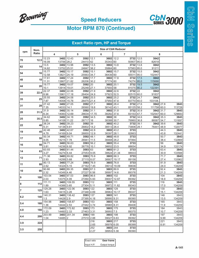
A-141
3000SERIESCbN
CbN
Serie
sExact Ratio rpm, HP and Torque
Speed Reducers
Motor RPM 870 (Continued)
Exact ratio Gear frame
Input H.P. Output torque
rpmNom.
Ratio
Size of CbN Reducer
4 5 6 7 8
70 12.512.23 3482 12.43 3592 12.1 3602 12.2 3732 12.5 3842
16.09 13706 28.2 24410 42 35343 60 50907 95.0 82618
62 1413.5 3482 13.98 3592 13.5 3602 13.8 3732 13.8 3842
14.62 13752 25.51 24847 38.2 35864 60 57583 95.0 91211
54 1615.77 3482 15.17 3592 15.1 3602 15.7 3732 15.5 3842
12.58 13821 24.19 25563 34.7 36439 60 65511 95.0 102447
48 1817.61 3482 17.24 3592 17.7 3602 17.8 3732 17.5 3842
11.31 13867 21.82 26206 30.2 37174 60 74274 95.0 115666
44 2019.77 3482 19.07 3592 20 3602 20.1 3732 19.5 3842
10.1 13914 19.01 25248 27.1 37693 58 81075 90.2 122391
39 22.422.37 3482 22.06 3592 21.9 3602 22.6 3732 22 3842
8.96 13961 17.18 26404 24.9 37923 52.5 82515 60.0 91837
35 2525.55 3482 24.08 3592 25.5 3602 25.2 3732 24.7 3842
7.87 14008 15.78 26475 21.4 37950 47.8 83770 60.0 103108.
31 2827.42 3482 27.05 3592 27.7 3602 28.4 3732 27.6 3842 27.8 3843
7.35 14033 14.1 26560 19.8 38142 43.1 85125 58.2 111758 60.0 113728
28 31.531.9 3482 30.14 3592 31.1 3602 31.8 3732 30.9 3842 31.7 3843
6.34 14083 12.69 26634 17.70 38282 37.6 83153 47.7 102547 60.0 129683
25 35.534.62 3482 34.18 3592 34.5 3602 36 3732 34.6 3842 35.3 3843
5.85 14108 11.22 26717 16 38388 30.7 76860 36.8 88587 54.7 131697
22 4038.24 3482 39.23 3592 39 3602 40.2 3732 39.1 3842 39.6 3843
5.31 14138 9.81 26802 14.2 38513 26.4 73806 28.1 76441 48.9 132077
19 4542.46 3482 42.67 3592 42.8 3602 43.2 3733 44.3 3843
4.79 14169 9.04 26855 12.9 38397 28.1 82663 43.8 132441
17 5050.34 3482 49.71 3592 48.1 3602 48.8 3733 50.7 3843
4.05 14215 7.78 26941 11.5 38468 26.2 87064 38.4 132869
16 5654.71 3483 56.63 3593 56.2 3603 55.4 3733 56 3843
3.81 14236 6.92 26776 10.1 38652 23.5 88654 34.9 133174
14 6363.93 3483 61.44 3593 63 3603 61.2 3733 63.4 3843
3.27 14274 6.44 27053 9.05 38824 21.34 88933 30.9 133566
12 7171.36 3483 69.82 3593 70.8 3603 68.3 3733 71.7 3843
2.93 14299 5.68 27115 8.07 38907 19.17 89158 27.4 133962
11 8080.13 3483 77.24 3593 76.9 3603 76.8 3733 81.9 3843
2.62 14324 5.15 27162 7.45 39012 19.09 99836 24.0 134209
10 9090.66 3483 89.35 3593 87.3 3603 89.9 3733 92.4 3843
2.32 14349 4.46 27227 6.56 38997 14.6 89378 21.3 134209
9 100103.54 3483 97.53 3593 96.6 3603 102 3733 104 3843
2.03 14375 4.09 27260 5.93 39007 12.87 89392 18.9 134209
8 112111.11 3483 109.55 3593 112 3603 111 3733 116 3843
1.89 14388 3.65 27304 5.11 38972 11.82 89343 17.0 134209
7 125129.28 3483 122.06 3593 122 3603 129 3733 130 3843
1.63 14415 3.28 27348 4.69 38963 10.17 89337 15.1 134209
6.2 140140.31 3483 138.42 3593 137 3603 141 3733 146 3843
1.5 14428 2.9 27395 4.18 38995 9.31 89390 13.5 134209
5.4 160154.98 3483 158.87 3593 153 3603 158 3733 165 3843
1.36 14444 2.53 27442 3.74 38965 8.31 89408 11.9 134209
4.8 180172.09 3483 172.82 3593 173 3603 175 3733 184 3843
1.23 14460 2.33 27463 3.31 38993 7.5 89375 10.7 134209
4.4 200203.99 3483 201.34 3593 199 3603 198 3733 197 3843
1.04 14485 2 27510 2.88 39027 6.63 89392 9.99 134209
3.9 224216 3603 217 3733 221 3843
2.65 38978 6.05 89399 8.91 134209
3.5 250252 3603 244 3733
2.27 38953 5.38 89390

A-142
3000SERIESCbN
CbN
Serie
s Exact Ratio rpm, HP and Torque
Speed Reducers
Combined - Motor RPM 1750
Exact ratio Gear frame
Input H.P. Output torque
rpmNom.
Ratio
Size of CbN Reducer
2 3 4 5 6 7 8
12.5 140
10.9 160
9.7 180
8.8 200
7.8 224223.5 3254 223.2 3374 229.4 3484 228.2 3594 210.21 3844
0.545 4038 0.964 7132 1.869 14206 3.556 26890 17.53 122392
7 250247.2 3254 246.8 3374 241.5 3484 258.3 3594 238.49 3844
0.493 4038 0.872 7132 1.775 14206 3.142 26890 15.45 122392
6.3 280260.2 3254 259.8 3374 273.4 3484 291.5 3594 280.01 3604 272.1 3734 263.25 3844
0.468 4038 0.829 7132 1.568 14206 2.784 26890 4.148 38582 9.128 82505 14.00 122392
5.6 315308.9 3254 308.4 3374 308.5 3484 329.7 3594 299.1 3604 310.07 3734 307.52 3844
0.395 4038 0.698 7132 1.39 14206 2.462 26890 3.883 38580. 8.01 82503 11.98 122392
4.9 355330.8 3254 330.2 3374 349 3484 374.5 3594 339.486 3604 357.53 3734 343.39 3844
0.368 4038 0.652 7132 1.229 14206 2.167 26890 3.422 38590 6.947 82506 10.73 122392
4.4 400370.4 3254 369.8 3374 396.5 3484 428 3594 377.19 3604 381.94 3734 385.52 3844
0.329 4038 0.582 7132 1.081 14206 1.896 26890 3.079 38578 6.503 82506 9.56 122392
3.9 450431.3 3254 430.6 3374 453 3484 483.1 3594 428.34 3604 433.47 3734 436.22 3844
0.283 4038 0.5 7132 0.946 14206 1.68 26890 2.711 38574 5.73 82507 8.45 122392
3.5 500465 3254 464.2 3374 511.4 3484 512.7 3594 476.66 3604 481.61 3734 498.23 3844
0.262 4038 0.464 7132 0.838 14206 1.583 26890 2.437 38587 5.157 82503 7.40 122392
3.1 560547 3254 546.1 3374 542.6 3484 608.8 3594 536.13 3604 546.92 3734 534.69 3844
0.223 4038 0.394 7132 0.79 14206 1.333 26890 2.167 38592 4.541 82500 6.89 122392
2.8 630613.1 3254 612.1 3374 644.4 3484 643.8 3594 628.53 3604 608.62 3734 622.05 3844
0.199 4038 0.352 7132 0.665 14206 1.261 26890 1.848 38583 4.081 82507 5.92 122392
2.5 710689.4 3254 688.3 3374 681.4 3484 735.7 3594 693.84 3604 684.55 3734 675.09 3844
0.177 4038 0.313 7132 0.629 14206 1.103 26890 1.674 38582 3.628 82499 5.46 122392
2.2 800775.1 3254 773.8 3374 778.7 3484 821.3 3594 760.75 3604 802.53 3734 745.68 3844
0.157 4038 0.278 7132 0.551 14206 0.988 26890 1.527 38588 3.095 82508 4.94 122392
1.9 900873.9 3254 872.4 3374 869.3 3484 920.8 3594 888.36 3604 885.92 3734 827.97 3844
0.139 4038 0.247 7132 0.493 14206 0.881 26890 1.308 38598 2.804 82518 4.45 122392
1.8 1000983.8 3254 982.2 3374 974.5 3484 1066.1 3594 986.89 3605 971.35 3734 981.63 3844
0.124 4038 0.219 7132 0.44 14206 0.761 26890 1.202 38616 2.557 82506 3.75 122392
1.6 11201082.3 3254 1080.5 3374 1128.3 3484 1170.6 3594 1136.34 3605 1134.29 3734 1066.85 3845
0.113 4038 0.199 7132 0.38 14206 0.693 26890 1.043 38583 2.19 82517 3.52 122392
1.4 12501221.3 3254 1219.3 3374 1239 3484 1342.4 3594 1214.4 3605 1258.82 3735 1246.64 3845
0.1 4038 0.177 7132 0.346 14206 0.605 26890 0.976 38584. 2.013 82492 3.02 122392
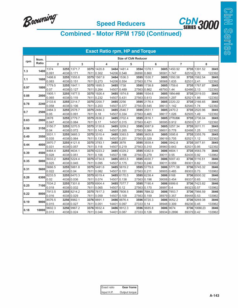
A-143
3000SERIESCbN
CbN
Serie
sSpeed Reducers
Combined - Motor RPM 1750 (Continued)
Exact ratio Gear frame
Input H.P. Output torque
Exact Ratio rpm, HP and Torque
rpmNom.
Ratio
Size of CbN Reducer
2 3 4 5 6 7 8
1.3 14001374 3255 1371.7 3375 1420.8 3484 1481.4 3594 1378.1 3605 1450.92 3735 1391.52 3845
0.091 4038 0.171 7611 0.302 14206 0.548 26890 0.860 38581 1.747 82516 2.70 122392
1.1 16001498.6 3255 1555.6 3375 1567.9 3484 1536.3 3595 1530.7 3605 1550.58 3735 1562.54 3845
0.083 4038 0.151 7611 0.273 14206 0.554 27563 0.774 38568 1.635 82531 2.41 122392
0.97 18001779.5 3255 1847.1 3375 1695.5 3485 1738 3595 1738.8 3605 1759.6 3735 1767.87 3845
0.07 4038 0.127 7611 0.264 14507 0.489 27563 0.862 48793 1.44 82486 2.13 122392
0.88 20001905.1 3255 1977.5 3375 1926.4 3485 1974.8 3595 1934.6 3605 1954.448 3735 2019.03 3845
0.065 4038 0.119 7611 0.232 14507 0.431 27563 0.613 38606 1.297 82521 1.86 122392
0.78 22402133.6 3255 2214.7 3375 2200.7 3485 2256 3595 2176.4 3605 2220.22 3735 2166.65 3845
0.058 4038 0.106 7611 0.203 14507 0.377 27563 0.545 38613 1.142 82540 1.74 122392
0.7 25002484.3 3255 2578.7 3375 2484.3 3485 2546.7 3595 2551.1 3605 2470.2 3735 2520.96 3845
0.05 4038 0.091 7611 0.18 14507 0.334 27563 0.465 38617 1.026 82505 1.49 122392
0.63 28002678 3255 2779.7 3375 2636.2 3485 2702.4 3595 2816.1 3605 2778.896 3735 2736.04 3845
0.047 4038 0.084 7611 0.17 14507 0.315 27563 0.421 38595 0.912 82503 1.37 122392
0.56 31503150.7 3255 3270.5 3375 3130.6 3485 3209.2 3595 3087.9 3605 3257.34 3735 3011.11 3845
0.04 4038 0.072 7611 0.143 14507 0.265 27563 0.384 38601 0.778 82498 1.25 122392
0.49 35503531.1 3255 3665.3 3375 3310.4 3485 3393.5 3595 3605.8 3605 3595.6 3735 3355.76 3845
0.035 4038 0.064 7611 0.135 14507 0.251 27563 0.329 38619 0.705 82521 1.12 122392
0.44 40003970.7 3255 4121.6 3375 3783.1 3485 3878 3595 3939.4 3606 3942.8 3735 3977.81 3845
0.031 4038 0.057 7611 0.118 14507 0.219 27563 0.310 38960 0.643 82531 0.95 122392
0.39 45004464.4 3255 4634.1 3375 4223.2 3485 4329.2 3595 4382.9 3606 4604.1 3735 4583.78 3846
0.028 4038 0.051 7611 0.106 14507 0.196 27563 0.279 39011 0.55 82435 0.92 133962
0.35 50005033.2 3255 5224.4 3375 4734.6 3485 4853.5 3595 4930.7 3606 5007.43 3736 5116.51 3846
0.025 4038 0.045 7611 0.095 14507 0.175 27563 0.248 39011 0.559 89301 0.82 133962
0.31 56005666.5 3255 5881.8 3375 5481.6 3485 5619.2 3595 5779.6 3606 5771.58 3736 5745.32 3846
0.022 4038 0.04 7611 0.082 14507 0.151 27563 0.211 38905 0.485 89303 0.73 133962
0.28 63006233.5 3255 6470.3 3375 6019.4 3485 6170.5 3595 6238.4 3606 6168 3736 6500.32 3846
0.02 4038 0.036 7611 0.074 14507 0.138 27563 0.196 39008 0.454 89337 0.65 133962
0.25 71007034.2 3255 7301.6 3375 6904.4 3485 7077.7 3595 7190.4 3606 6999.6 3736 7423.82 3846
0.018 4038 0.032 7611 0.065 14507 0.12 27563 0.170 38997 0.4 89323 0.57 133962
0.22 80007913.5 3255 8214.2 3375 7617.3 3485 7808.5 3595 7684.32 3606 7853.7 3736 7966.59 3846
0.016 4038 0.029 7611 0.059 14507 0.109 27563 0.159 38979 0.357 89448 0.53 133962
0.19 90008576.5 3256 8982.1 3376 8891.1 3486 8876.4 3596 8720.3 3606 9052.2 3736 9269.38 3846
0.015 4038 0.027 7611 0.051 14401 0.097 27333 0.14 38948 0.309 89236 0.45 133962
0.18 100009602.3 3256 9967.2 3376 9932.4 3486 9912.3 3596 9685.8 3606 9674 3736 10060.23 3846
0.013 4038 0.024 7611 0.046 14401 0.087 27333 0.126 38934 0.2896 89379 0.42 133962
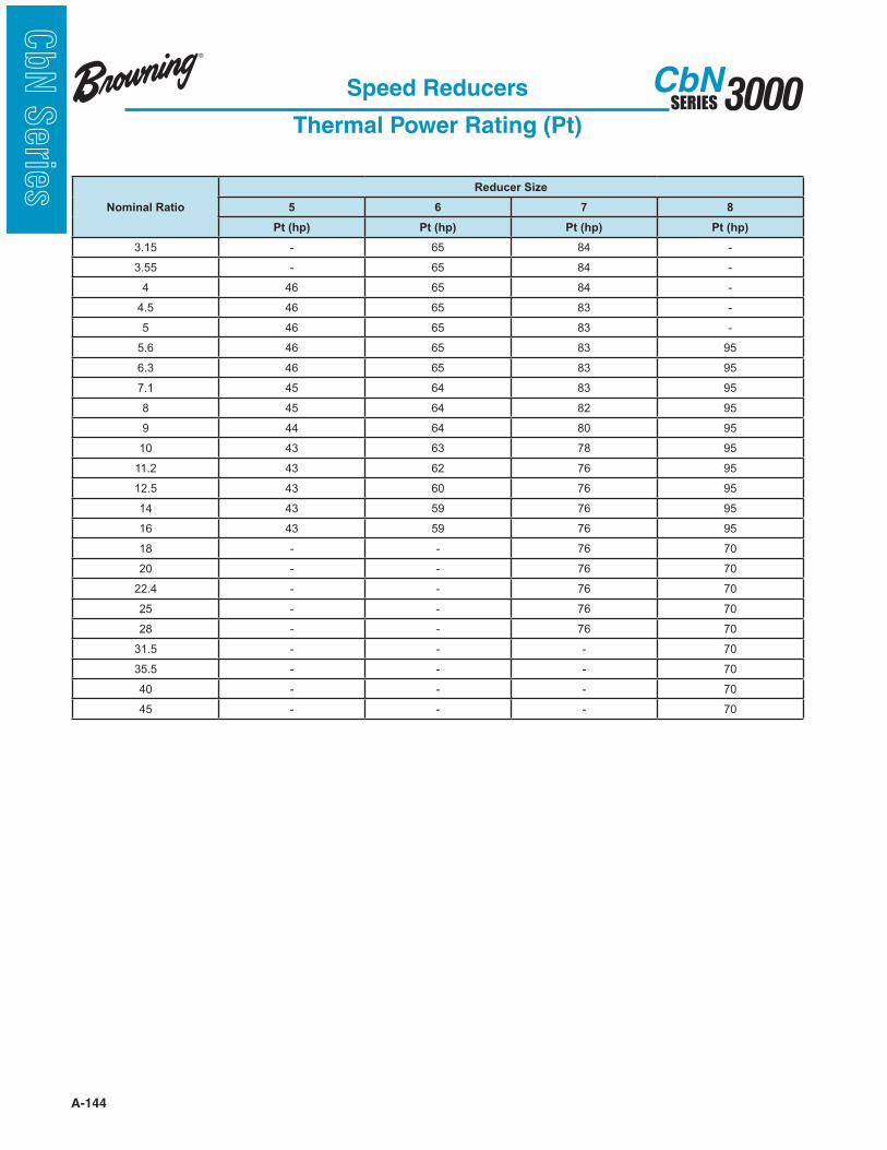
A-144
3000SERIESCbN
CbN
Serie
s
Speed Reducers
Thermal Power Rating (Pt)
Nominal Ratio
Reducer Size
5 6 7 8
Pt (hp) Pt (hp) Pt (hp) Pt (hp)
3.15 - 65 84 -
3.55 - 65 84 -
4 46 65 84 -
4.5 46 65 83 -
5 46 65 83 -
5.6 46 65 83 95
6.3 46 65 83 95
7.1 45 64 83 95
8 45 64 82 95
9 44 64 80 95
10 43 63 78 95
11.2 43 62 76 95
12.5 43 60 76 95
14 43 59 76 95
16 43 59 76 95
18 - - 76 70
20 - - 76 70
22.4 - - 76 70
25 - - 76 70
28 - - 76 70
31.5 - - - 70
35.5 - - - 70
40 - - - 70
45 - - - 70
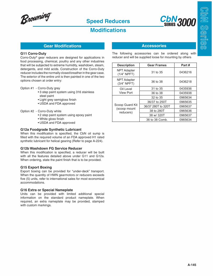
A-145
3000SERIESCbN
CbN
Serie
sGear Modifications
G11 Corro-DutyCorro-Duty® gear reducers are designed for applications in food processing, chemical, poultry and any other industries that will be subjected to extreme humidity, washdown, steam, detergents, and mild acids. Construction of the Corro-Duty reducer includes the normally closed breather in the gear case. The exterior of the entire unit is then painted in one of the two options chosen at order entry:
Option #1 - Corro-Duty grey steel paint
Option #2 - Corro-Duty white
G12a Foodgrade Synthetic LubricantWhen this modification is specified, the CbN oil sump is filled with the required volume of an FDA approved H1 rated synthetic lubricant for helical gearing (Refer to page A-224).
G12b Washdown FG Service ReducerWhen this modification is specified, a reducer will be built with all the features detailed above under G11 and G12a. When ordering, state the paint finish that is to be provided.
G15 Export BoxingExport boxing can be provided for “under-deck” transport. When the quantity of HWN gearmotors or reducers exceeds five (5) units, refer to international sales for most economical accommodations.
G16 Extra or Special NameplateUnits can be provided with limited additional special information on the standard product nameplate. When required, an extra nameplate may be provided, stamped with custom markings.
Accessories
Speed Reducers
Modifications
The following accessories can be ordered along with reducer and will be supplied loose for mounting by others
Description Gear Frames Part #
NPT Adapter
(1/4” NPFT)31 to 35 0436216
NPT Adapter
(3/4” NPFT)36 to 38 0436218
Oil Level
View Port
31 to 35 0435936
36 to 38 0435938
Scoop Guard Kit
(scoop mount
reducers)
32 to 35 0965634
36/37 to 250T 0965635
36/37 280T to 320T 0965637
38 to 280T 0965636
38 w/ 320T 0965637
36 to 38 Comb. 0965634
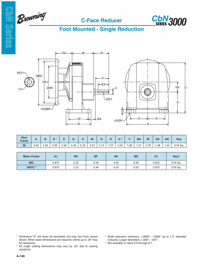
A-146
3000SERIESCbN
CbN
Serie
s
C-Face Reducer
Foot Mounted - Single Reduction
1 Dimension “D” will never be exceeded, but may vary from values
be necessary.2
variations.
3
4 Not available in ratios 5.6 through 8:1.
ES
V
N
U
2F
B
BA
O
D
E
XN
E
A
G
RU M
ØAJ
KEY
(4)ØBF
ØAK
KEY1
U1
(4)ØH
ØBD
Gear
FrameA B D 1 E G H M N O U 3 V BA 2F ES XN Key
30 5.90 3.54 2.95 2.46 0.49 0.35 3.03 2.14 7.07 0.63 1.88 1.01 2.76 1.48 1.40 3/16 Sq.
Motor Frame AJ RU BF AK BD U1 Key1
56C 5.875 3.33 0.44 4.50 6.50 0.625 3/16 Sq.
140TC 4 5.875 3.33 0.44 4.50 6.50 0.875 3/16 Sq.
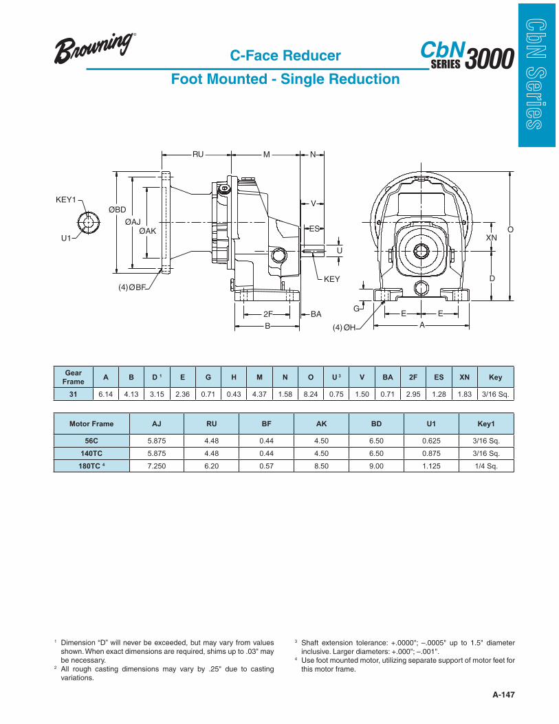
A-147
3000SERIESCbN
CbN
Serie
s
M
ES O
GEE
A
U
KEY
2F
B
D
XN
N
BA
(4) ØH
ØAJ
RU
(4)ØBF
V
ØAK
ØBD
U1
KEY1
C-Face Reducer
Foot Mounted - Single Reduction
1 Dimension “D” will never be exceeded, but may vary from values
be necessary.2
variations.
3
4 Use foot mounted motor, utilizing separate support of motor feet for this motor frame.
Gear
FrameA B D 1 E G H M N O U 3 V BA 2F ES XN Key
31 6.14 4.13 3.15 2.36 0.71 0.43 4.37 1.58 8.24 0.75 1.50 0.71 2.95 1.28 1.83 3/16 Sq.
Motor Frame AJ RU BF AK BD U1 Key1
56C 5.875 4.48 0.44 4.50 6.50 0.625 3/16 Sq.
140TC 5.875 4.48 0.44 4.50 6.50 0.875 3/16 Sq.
180TC 4 7.250 6.20 0.57 8.50 9.00 1.125 1/4 Sq.
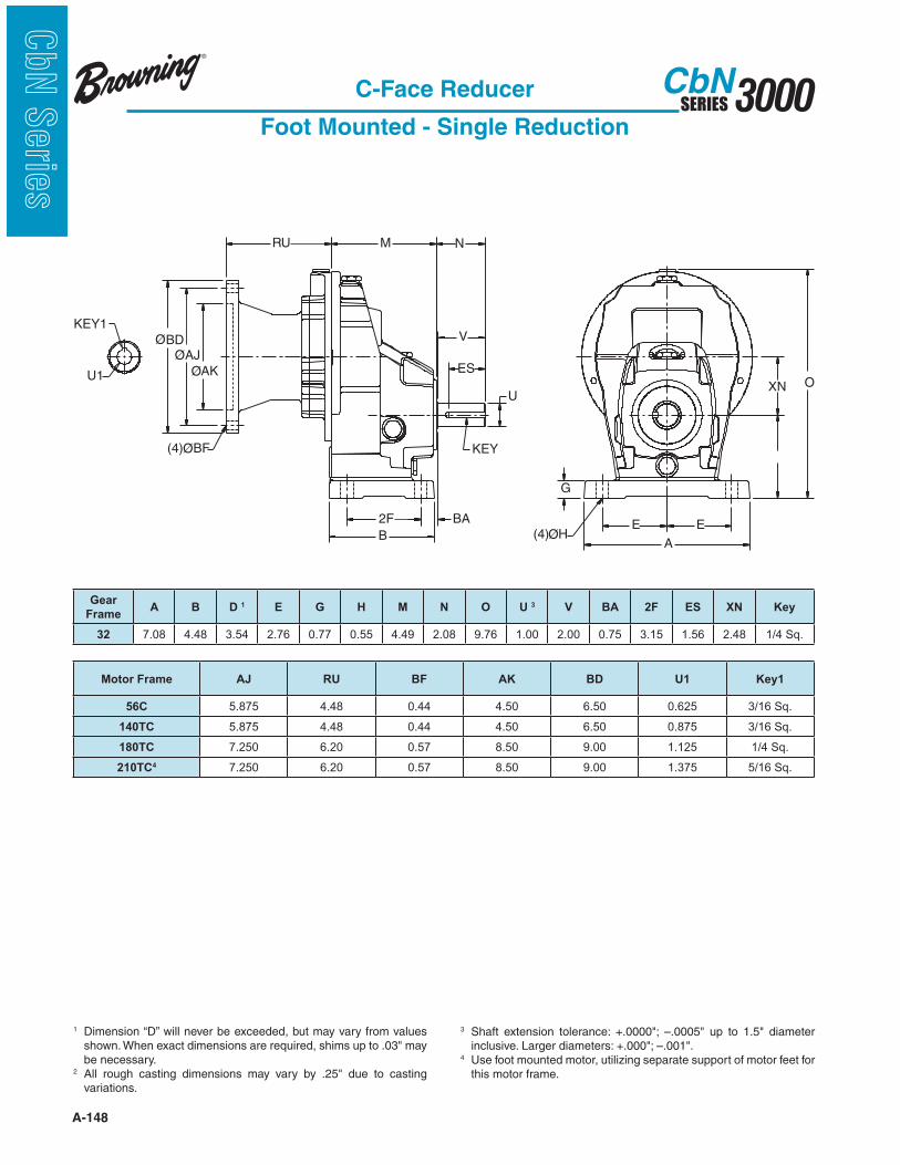
A-148
3000SERIESCbN
CbN
Serie
s
ØAK
ØBD
ES
V
N
U
2F
B
BA
O
E
XN
E
A
G
RU M
ØAJ
KEY1
U1
KEY(4)ØBF
(4)ØH
C-Face Reducer
Foot Mounted - Single Reduction
1 Dimension “D” will never be exceeded, but may vary from values
be necessary.2
variations.
3
4 Use foot mounted motor, utilizing separate support of motor feet for this motor frame.
Gear
FrameA B D 1 E G H M N O U 3 V BA 2F ES XN Key
32 7.08 4.48 3.54 2.76 0.77 0.55 4.49 2.08 9.76 1.00 2.00 0.75 3.15 1.56 2.48 1/4 Sq.
Motor Frame AJ RU BF AK BD U1 Key1
56C 5.875 4.48 0.44 4.50 6.50 0.625 3/16 Sq.
140TC 5.875 4.48 0.44 4.50 6.50 0.875 3/16 Sq.
180TC 7.250 6.20 0.57 8.50 9.00 1.125 1/4 Sq.
210TC4 7.250 6.20 0.57 8.50 9.00 1.375 5/16 Sq.
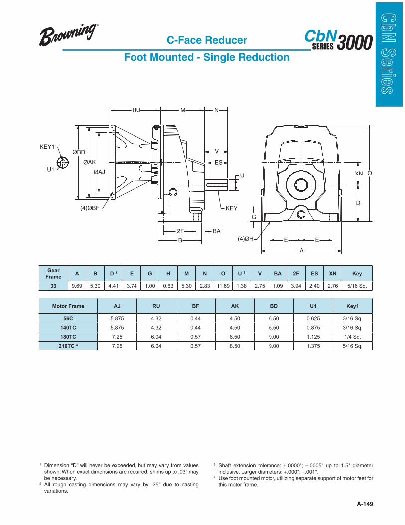
A-149
3000SERIESCbN
CbN
Serie
sC-Face Reducer
Foot Mounted - Single Reduction
1 Dimension “D” will never be exceeded, but may vary from values
be necessary.2
variations.
3
4 Use foot mounted motor, utilizing separate support of motor feet for this motor frame.
ES
V
N
U
KEY
2F
B
BA
O
D
E
XN
E
A
G
RU M
ØAJU1
KEY1
ØAK
ØBD
(4)ØH
(4)ØBF
Gear
FrameA B D 1 E G H M N O U 3 V BA 2F ES XN Key
33 9.69 5.30 4.41 3.74 1.00 0.63 5.30 2.83 11.69 1.38 2.75 1.09 3.94 2.40 2.76 5/16 Sq.
Motor Frame AJ RU BF AK BD U1 Key1
56C 5.875 4.32 0.44 4.50 6.50 0.625 3/16 Sq.
140TC 5.875 4.32 0.44 4.50 6.50 0.875 3/16 Sq.
180TC 7.25 6.04 0.57 8.50 9.00 1.125 1/4 Sq.
210TC 4 7.25 6.04 0.57 8.50 9.00 1.375 5/16 Sq.
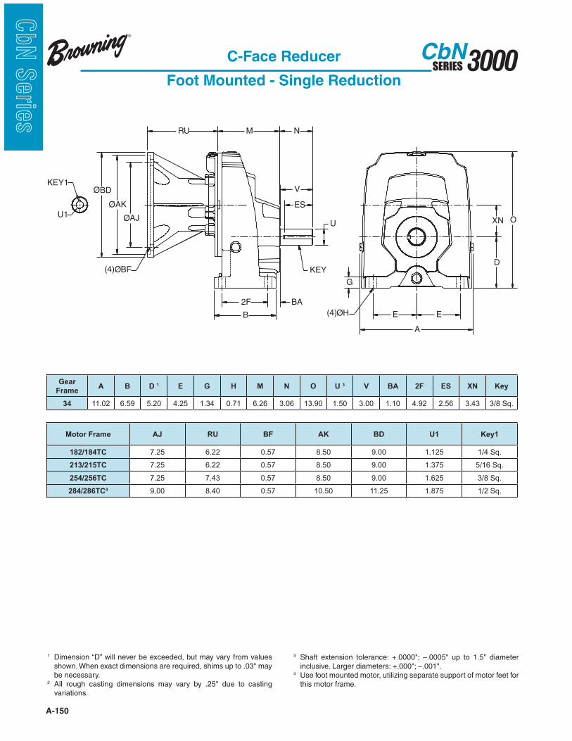
A-150
3000SERIESCbN
CbN
Serie
s
C-Face Reducer
Foot Mounted - Single Reduction
1 Dimension “D” will never be exceeded, but may vary from values
be necessary.2
variations.
3
4 Use foot mounted motor, utilizing separate support of motor feet for this motor frame.
ES
V
N
U
KEY
2F
B
BA
O
D
E
XN
E
A
G
RU M
ØAJU1
KEY1
ØAK
ØBD
(4)ØH
(4)ØBF
Gear
FrameA B D 1 E G H M N O U 3 V BA 2F ES XN Key
34 11.02 6.59 5.20 4.25 1.34 0.71 6.26 3.06 13.90 1.50 3.00 1.10 4.92 2.56 3.43 3/8 Sq.
Motor Frame AJ RU BF AK BD U1 Key1
182/184TC 7.25 6.22 0.57 8.50 9.00 1.125 1/4 Sq.
213/215TC 7.25 6.22 0.57 8.50 9.00 1.375 5/16 Sq.
254/256TC 7.25 7.43 0.57 8.50 9.00 1.625 3/8 Sq.
284/286TC4 9.00 8.40 0.57 10.50 11.25 1.875 1/2 Sq.

A-151
3000SERIESCbN
CbN
Serie
sC-Face Reducer
Foot Mounted - Single Reduction
1 Dimension “D” will never be exceeded, but may vary from values
be necessary.2
variations.
3
4 Use foot mounted motor, utilizing separate support of motor feet for this motor frame.
ES
V
N
U
KEY
2F
B
BA
O
D
E
XN
E
A
G
RU M
ØAJU1
KEY1
ØAK
ØBD
(4)ØH
(4)ØBF
Gear
FrameA B D 1 E G H M N O U 3 V BA 2F ES XN Key
35 13.65 7.76 6.30 5.12 1.61 0.79 6.83 3.56 17.37 1.75 3.50 1.18 6.30 3.06 4.33 3/8 Sq.
Motor Frame AJ RU BF AK BD U1 Key1
213/215TC 7.25 5.87 0.57 8.50 9.00 1.375 5/16 Sq.
254/256TC 7.25 7.09 0.57 8.50 9.00 1.625 3/8 Sq.
284/286TC4 9.00 8.06 0.57 10.50 11.25 1.875 1/2 Sq.
324/326TC4 11.00 8.79 0.69 12.50 13.38 2.125 1/2 Sq.

A-152
3000SERIESCbN
CbN
Serie
s
ØAJ
ØAK
ØBD
KEY
(4)ØH(4)ØBF
KEY1
RU
ES
V
N
U
BA2F
B
GE E
A
D
XN
O
M
U1
C-Face Reducer
Foot Mounted - Double/Triple Reduction
1 Dimension “D” will never be exceeded, but may vary from values
be necessary.2
variations.
3
4 Not available for ratio 31.5 to 45:1 in 3012. Use 3013 for 35.5 to 45:1.
Gear
FrameA B D 1 E G H M N O U 3 V BA 2F ES XN Key
3012 5.90 4.92 2.95 2.46 0.51 0.35 4.13 1.83 6.00 0.75 1.75 0.87 4.13 1.48 0.28 3/16 Sq.
3013 5.90 5.71 2.95 2.46 0.51 0.35 4.92 1.83 6.00 0.75 1.75 0.87 4.92 1.48 0.28 3/16 Sq.
Motor Frame AJ RU BF AK BD U1 Key1
56C 5.875 3.33 0.44 4.50 6.50 0.625 3/16 Sq.
140TC 4 5.875 3.33 0.44 4.50 6.50 0.875 3/16 Sq.
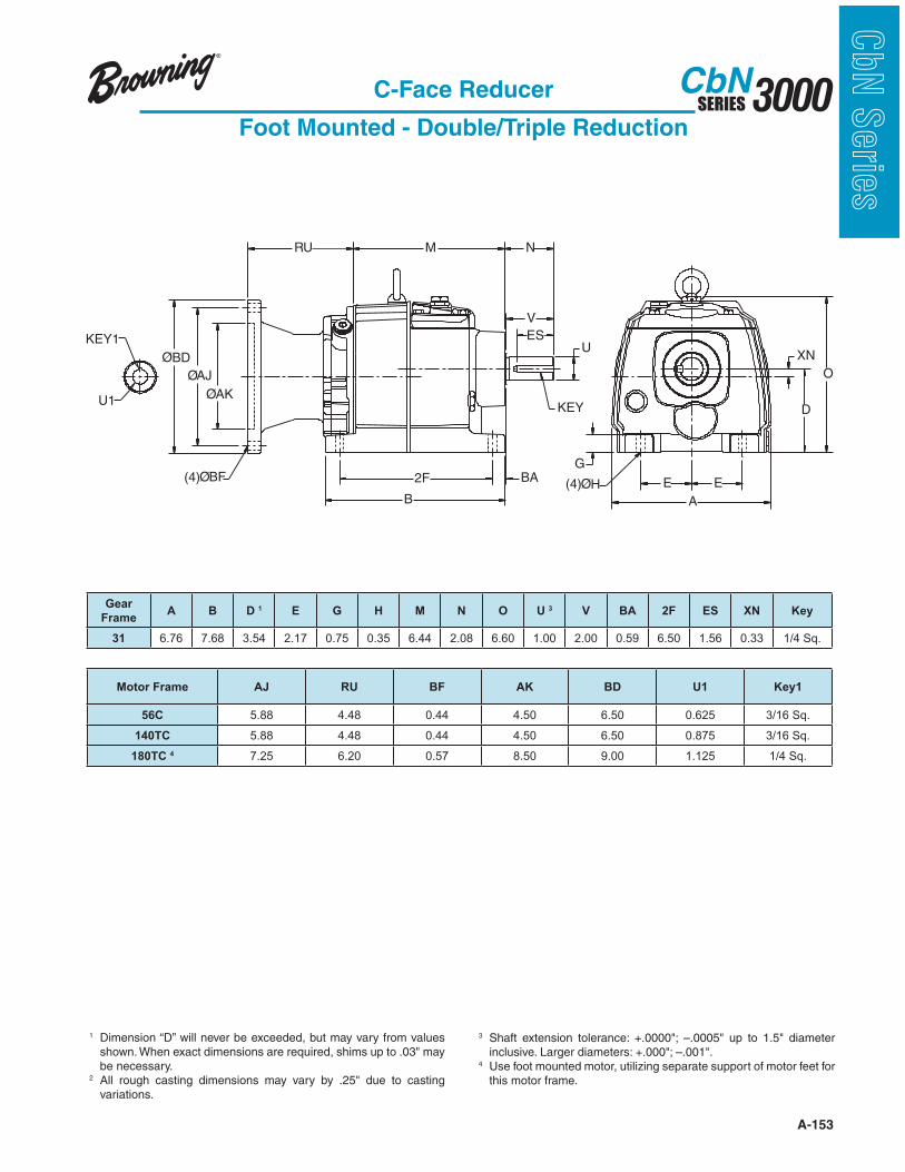
A-153
3000SERIESCbN
CbN
Serie
s
V
ES
NM
2F
B
G
U
E E
A
KEY
O
(4)ØHBA
ØAJ
(4)ØBF
RU
XN
D
KEY1
U1ØAK
ØBD
C-Face Reducer
Foot Mounted - Double/Triple Reduction
1 Dimension “D” will never be exceeded, but may vary from values
be necessary.2
variations.
3
4 Use foot mounted motor, utilizing separate support of motor feet for this motor frame.
Gear
FrameA B D 1 E G H M N O U 3 V BA 2F ES XN Key
31 6.76 7.68 3.54 2.17 0.75 0.35 6.44 2.08 6.60 1.00 2.00 0.59 6.50 1.56 0.33 1/4 Sq.
Motor Frame AJ RU BF AK BD U1 Key1
56C 5.88 4.48 0.44 4.50 6.50 0.625 3/16 Sq.
140TC 5.88 4.48 0.44 4.50 6.50 0.875 3/16 Sq.
180TC 4 7.25 6.20 0.57 8.50 9.00 1.125 1/4 Sq.

A-154
3000SERIESCbN
CbN
Serie
s
U1
KEY1
ØAJ
ØBD
(4)ØH(4)ØBF
ØAK
RU
ES
V
N
U
KEY
BA2F
B
G
E E
A
D
XN
O
M
C-Face Reducer
Foot Mounted - Double/Triple Reduction
1 Dimension “D” will never be exceeded, but may vary from values
be necessary.2
variations.
3
4 Use foot mounted motor, utilizing separate support of motor feet for this motor frame.
Gear
FrameA B D 1 E G H M N O U 3 V BA 2F ES XN Key
32 8.72 8.50 4.53 2.66 0.84 0.55 7.13 2.56 7.97 1.25 2.50 0.51 7.56 2.16 0.39 1/4 Sq.
Motor Frame AJ RU BF AK BD U1 Key1
56C 5.875 4.48 0.44 4.50 6.50 0.625 3/16 Sq.
140TC 5.875 4.48 0.44 4.50 6.50 0.875 3/16 Sq.
180TC 7.25 6.20 0.57 8.50 9.00 1.125 1/4 Sq.
210TC 4 7.25 6.20 0.57 8.50 9.00 1.375 5/16 Sq.
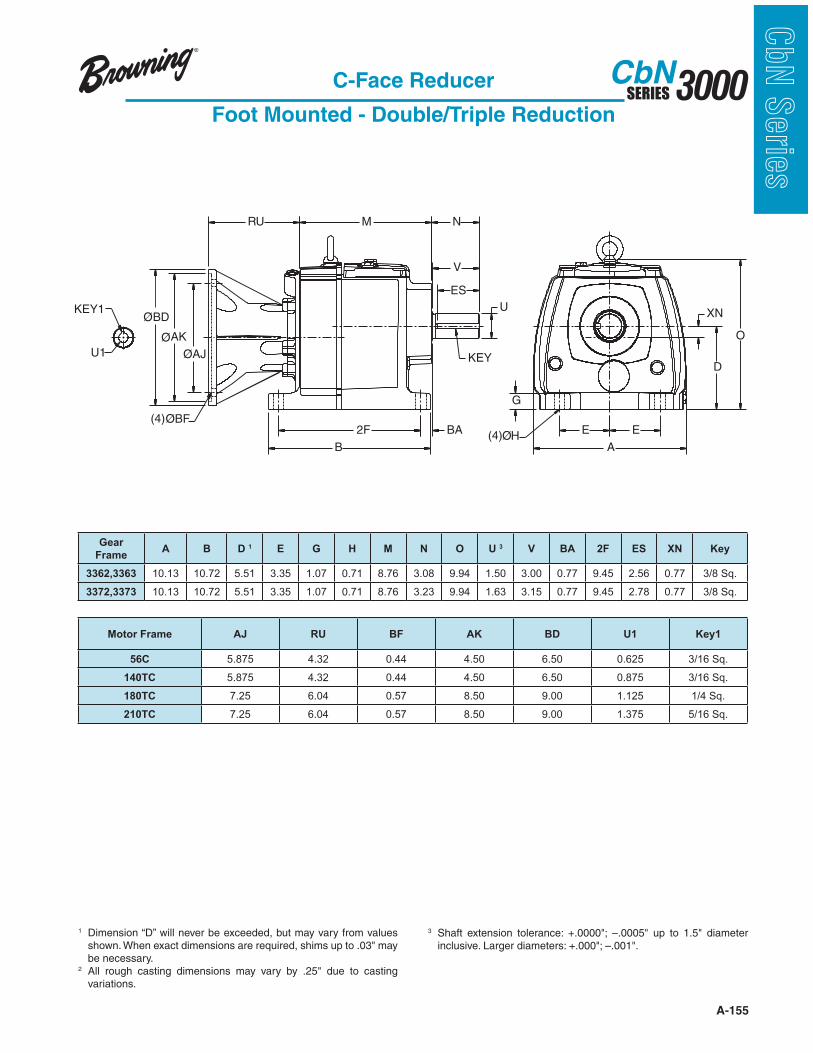
A-155
3000SERIESCbN
CbN
Serie
s
RU
ES
V
N
U
KEY
BA2F
B
G
E E
A
D
XN
O
M
KEY1
U1
ØBD
ØAJ
ØAK
(4)ØBF
(4)ØH
C-Face Reducer
Foot Mounted - Double/Triple Reduction
1 Dimension “D” will never be exceeded, but may vary from values
be necessary.2
variations.
3
Gear
FrameA B D 1 E G H M N O U 3 V BA 2F ES XN Key
3362,3363 10.13 10.72 5.51 3.35 1.07 0.71 8.76 3.08 9.94 1.50 3.00 0.77 9.45 2.56 0.77 3/8 Sq.
3372,3373 10.13 10.72 5.51 3.35 1.07 0.71 8.76 3.23 9.94 1.63 3.15 0.77 9.45 2.78 0.77 3/8 Sq.
Motor Frame AJ RU BF AK BD U1 Key1
56C 5.875 4.32 0.44 4.50 6.50 0.625 3/16 Sq.
140TC 5.875 4.32 0.44 4.50 6.50 0.875 3/16 Sq.
180TC 7.25 6.04 0.57 8.50 9.00 1.125 1/4 Sq.
210TC 7.25 6.04 0.57 8.50 9.00 1.375 5/16 Sq.

A-156
3000SERIESCbN
CbN
Serie
s
RU
ES
V
N
U
KEY
BA2F
B
G
E E
A
D
XN
O
M
KEY1
U1
ØBD
ØAJ
ØAK
(4)ØBF
(4)ØH
C-Face Reducer
Foot Mounted - Double/Triple Reduction
1 Dimension “D” will never be exceeded, but may vary from values
be necessary.2
variations.
3
4 Use foot mounted motor, utilizing separate support of motor feet for this motor frame.
Gear
FrameA B D 1 E G H M N O U 3 V BA 2F ES XN Key
34 11.97 10.87 7.09 4.53 1.37 0.71 9.80 3.58 11.89 2.13 3.50 0.98 9.25 3.06 1.02 1/2 Sq.
35 14.19 12.89 8.86 5.51 1.73 0.87 11.34 4.81 14.84 2.38 4.72 1.10 11.02 4.15 1.14 5/8 Sq.
Motor Frame Gear Frame AJ RU BF AK BD U1 Key1
56C All 5.875 4.14 0.44 4.50 6.50 0.625 3/16 Sq.
143/145TC All 5.875 4.14 0.44 4.50 6.50 0.875 3/16 Sq.
182/184TC All 7.250 5.87 0.57 8.50 9.00 1.125 1/4 Sq.
213/215TC All 7.250 5.87 0.57 8.50 9.00 1.375 5/16 Sq.
254/256TC All 7.250 7.09 0.57 8.50 9.00 1.625 3/8 Sq.
284/286TC 34 4, 35 9.000 8.06 0.57 10.50 11.25 1.875 1/2 Sq.
324/326TC 35 4 11.000 8.79 0.69 12.50 13.38 2.125 1/2 Sq.

A-157
3000SERIESCbN
CbN
Serie
s
B
XN
2F BA
N
V
ES
U
KEY
M
D
O
E E
A
G
(4) ØH
RU
(4)ØBF
ØBDØAK
ØAJ
KEY1
U1
C-Face Reducer
Foot Mounted - Double/Triple Reduction
1 Dimension “D” will never be exceeded, but may vary from values
be necessary.2
variations.
3
Gear
FrameA B D 1 E G H N O U3 V BA 2F ES XN M Key
36 17.68 15.95 9.85 6.99 1.77 1.02 5.847 17.72 2.875 5.75 2.36 13.98 4.784 1.102 13.86 3/4 Sq
37 20.39 17.91 12.40 8.27 2.17 1.02 7.127 20.40 3.625 7.00 2.56 15.35 5.893 2.362 16.54 7/8 Sq
38 23.94 21.65 13.98 10.04 2.35 1.02 9.99 22.60 4.375 9.99 1.97 18.90 9.02 2.559 19.88 1 SQ
Motor Frame Gear Frame AJ AK BF U1 RU BDX Key1
182TC-184TC 36,37 7.25 8.50 .50 1.125 5.26 9.00 1/4 Sq.
213TC-215TC36,37 7.25 4.50 .50 1.375 5.26 9.00 5/16 Sq.
38 7.25 4.50 .50 1.375 6.12 9.00 5/16 Sq.
254TC-256TC All 7.25 8.50 .50 1.625 6.12 9.00 3/8 Sq.
284TC-286TC All 9.00 10.50 .50 1.875 7.09 9.00 1/2 Sq.
324TC-326TC All 11.00 12.50 .625 2.125 8.45 13.38 1/2 Sq.
364TC-365TC 37,38 11.00 12.50 .625 2.375 8.45 13.38 5/8 Sq.
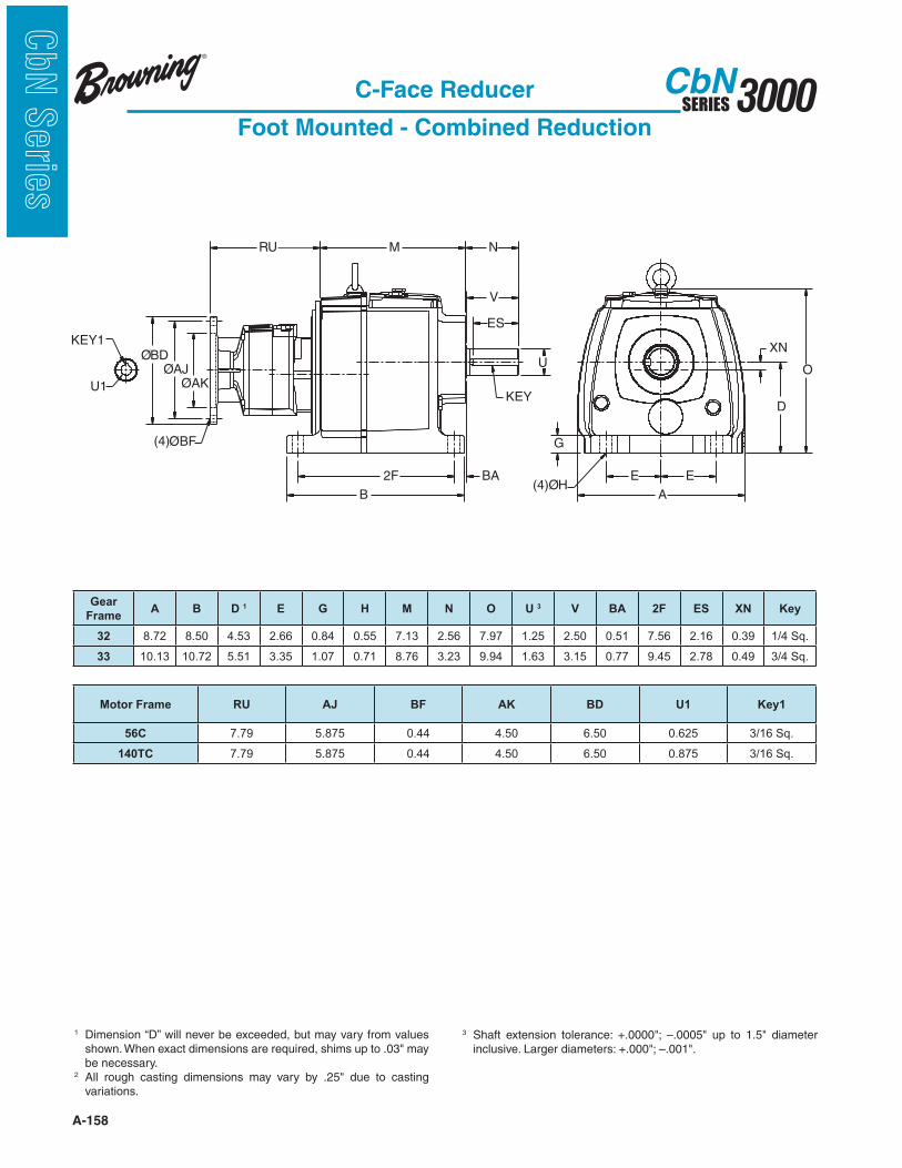
A-158
3000SERIESCbN
CbN
Serie
s
KEY1
(4)ØBF
(4)ØH
RU
ES
V
N
U
KEY
BA2F
B
G
E E
A
D
XN
O
M
ØBD
ØAK
ØAJ
U1
C-Face Reducer
Foot Mounted - Combined Reduction
1 Dimension “D” will never be exceeded, but may vary from values
be necessary.2
variations.
3
Gear
FrameA B D 1 E G H M N O U 3 V BA 2F ES XN Key
32 8.72 8.50 4.53 2.66 0.84 0.55 7.13 2.56 7.97 1.25 2.50 0.51 7.56 2.16 0.39 1/4 Sq.
33 10.13 10.72 5.51 3.35 1.07 0.71 8.76 3.23 9.94 1.63 3.15 0.77 9.45 2.78 0.49 3/4 Sq.
Motor Frame RU AJ BF AK BD U1 Key1
56C 7.79 5.875 0.44 4.50 6.50 0.625 3/16 Sq.
140TC 7.79 5.875 0.44 4.50 6.50 0.875 3/16 Sq.
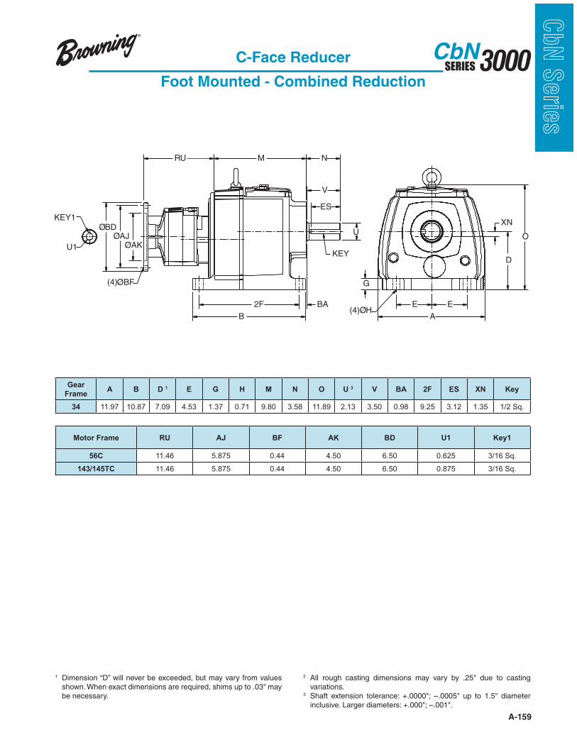
A-159
3000SERIESCbN
CbN
Serie
s
KEY1
(4)ØBF
(4)ØH
RU
ES
V
N
U
KEY
BA2F
B
G
E E
A
D
XN
O
M
ØBD
ØAK
ØAJ
U1
C-Face Reducer
Foot Mounted - Combined Reduction
1 Dimension “D” will never be exceeded, but may vary from values
be necessary.
2 variations.
3
Gear
FrameA B D 1 E G H M N O U 3 V BA 2F ES XN Key
34 11.97 10.87 7.09 4.53 1.37 0.71 9.80 3.58 11.89 2.13 3.50 0.98 9.25 3.12 1.35 1/2 Sq.
Motor Frame RU AJ BF AK BD U1 Key1
56C 11.46 5.875 0.44 4.50 6.50 0.625 3/16 Sq.
143/145TC 11.46 5.875 0.44 4.50 6.50 0.875 3/16 Sq.
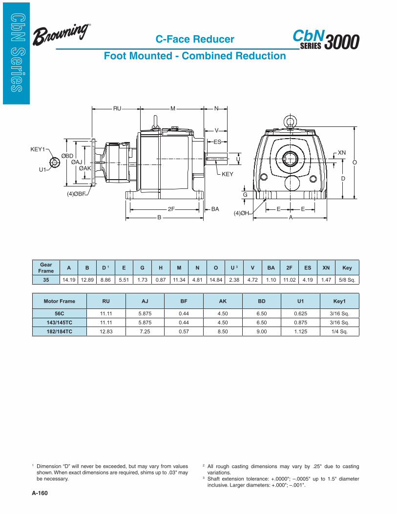
A-160
3000SERIESCbN
CbN
Serie
s
KEY1
(4)ØBF
(4)ØH
RU
ES
V
N
U
KEY
BA2F
B
G
E E
A
D
XN
O
M
ØBD
ØAK
ØAJ
U1
C-Face Reducer
Foot Mounted - Combined Reduction
1 Dimension “D” will never be exceeded, but may vary from values
be necessary.
2 variations.
3
Gear
FrameA B D 1 E G H M N O U 3 V BA 2F ES XN Key
35 14.19 12.89 8.86 5.51 1.73 0.87 11.34 4.81 14.84 2.38 4.72 1.10 11.02 4.19 1.47 5/8 Sq.
Motor Frame RU AJ BF AK BD U1 Key1
56C 11.11 5.875 0.44 4.50 6.50 0.625 3/16 Sq.
143/145TC 11.11 5.875 0.44 4.50 6.50 0.875 3/16 Sq.
182/184TC 12.83 7.25 0.57 8.50 9.00 1.125 1/4 Sq.
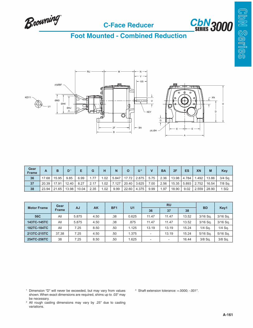
A-161
3000SERIESCbN
CbN
Serie
sC-Face Reducer
Foot Mounted - Combined Reduction
ØAK
ØAJ
RU
(4)ØBF
U1
KEY1
B
E E
A
G
(4) ØH
XN
D
O
2F BA
N
V
ES
U
KEY
M
ØBD
Gear
FrameA B D 1 E G H N O U 3 V BA 2F ES XN M Key
36 17.68 15.95 9.85 6.99 1.77 1.02 5.847 17.72 2.875 5.75 2.36 13.98 4.784 1.492 13.86 3/4 Sq
37 20.39 17.91 12.40 8.27 2.17 1.02 7.127 20.40 3.625 7.00 2.56 15.35 5.893 2.752 16.54 7/8 Sq
38 23.94 21.65 13.98 10.04 2.35 1.02 9.99 22.60 4.375 9.99 1.97 18.90 9.02 2.559 28.90 1 SQ
Motor FrameGear
FrameAJ AK BF1 U1
RUBD Key1
36 37 38
56C All 5.875 4.50 .38 0.625 11.47 11.47 13.52 3/16 Sq. 3/16 Sq.
143TC-145TC All 5.875 4.50 .38 .875 11.47 11.47 13.52 3/16 Sq. 3/16 Sq.
182TC-184TC All 7.25 8.50 .50 1.125 13.19 13.19 15.24 1/4 Sq. 1/4 Sq.
213TC-215TC 37,38 7.25 4.50 .50 1.375 - 13.19 15.24 5/16 Sq. 5/16 Sq.
254TC-256TC 38 7.25 8.50 .50 1.625 - - 16.44 3/8 Sq. 3/8 Sq.
1 Dimension “D” will never be exceeded, but may vary from values
be necessary.2
variations.
3
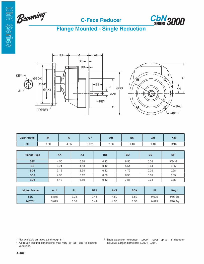
A-162
3000SERIESCbN
CbN
Serie
s
C-Face Reducer
Flange Mounted - Single Reduction
1 Not available on ratios 5.6 through 8:1.2
variations.
KEY1
(4)ØBF1(4)ØBF
ES
AH
BB
BE
ØAK
ØBDUXN
ØAJ
MRU
O
KEY
ØBDX
ØAK1
ØAJ1
U1
3
Gear Frame M O U 3 AH ES XN Key
30 3.50 4.65 0.625 2.06 1.48 1.40 3/16
Flange Type AK AJ BB BD BE BF
56C 4.50 5.88 0.12 6.50 0.39 3/8-16
BS 3.74 4.53 0.12 5.51 0.31 0.35
BD1 3.15 3.94 0.12 4.72 0.39 0.28
BD2 4.33 5.12 0.08 6.30 0.39 0.35
BD3 5.12 6.50 0.12 7.87 0.31 0.35
Motor Frame AJ1 RU BF1 AK1 BDX U1 Key1
56C 5.875 3.33 0.44 4.50 6.50 0.625 3/16 Sq.
140TC 1 5.875 3.33 0.44 4.50 6.50 0.875 3/16 Sq.

A-163
3000SERIESCbN
CbN
Serie
sC-Face Reducer
Flange Mounted - Single Reduction
M
ES
AH
O
U
KEYXD
XNØBD
ØAK
BBBE
AJ
(4)Ø
Ø
BF
RU
ØAJ1
ØAK1
ØBDX
(4)ØBF1
U1
KEY1
A
2 variations.
3
4 Permitted in vertical mounting only.
Gear Frame A M O U 3 AH ES XD XN Key
31 6.14 4.76 4.82 0.75 1.50 1.28 3.15 1.83 3/16 Sq.
Flange Type AK AJ BB BD BE BF
BS 4.33 5.12 0.14 6.29 0.39 0.35
BD2 3.74 4.53 0.14 5.50 0.39 0.35
Motor Frame AJ1 RU BF1 AK1 BDX U1 Key1
56C 5.875 4.48 0.44 4.50 6.50 0.625 3/16 Sq.
140TC 5.875 4.48 0.44 4.50 6.50 0.875 3/16 Sq.
180TC 4 7.250 6.20 0.57 8.50 9.00 1.125 1/4 Sq.

A-164
3000SERIESCbN
CbN
Serie
s
ES
AH
BB
BE
ØAK
ØBDUXN
ØAJ
(4)ØBF
MRU
O
U1
ØBDX
ØAK1
ØAJ1
(4)ØBF1
KEY1
KEY
C-Face Reducer
Flange Mounted - Single Reduction
2 variations.
3
4 Permitted in vertical mounting only.
Gear Frame M O U 3 AH ES XN Key
32 4.88 6.22 1.00 1.50 1.16 2.48 1/4 Sq.
Flange Type AK AJ BB BD BE BF
BS 5.12 6.5 0.14 7.87 0.47 0.47
BD2 4.33 5.12 0.14 6.29 0.39 0.35
Motor Frame AJ1 RU BF1 AK1 BDX U1 Key1
56C 5.875 4.48 0.44 4.50 6.50 0.625 3/16 Sq.
140TC 5.875 4.48 0.44 4.50 6.50 0.875 3/16 Sq.
180TC 7.250 6.20 0.57 8.50 9.00 1.125 1/4 Sq.
210TC 4 7.250 6.20 0.57 8.50 9.00 1.375 5/16 Sq.

A-165
3000SERIESCbN
CbN
Serie
s
KEY1
(4)ØBF1
A
ES
AH
BB
BE
ØAK
ØBDU
KEY
XN
ØAJ
(4)ØBF
MRU
XD
O
ØAJ1
ØBDX
U1
ØAK1
C-Face Reducer
Flange Mounted - Single Reduction
2 variations.
3
4 Permitted in vertical mounting only.
Gear Frame A M O U 3 AH ES XD XN Key
33 9.44 5.77 7.28 1.375 2.75 2.40 4.41 2.76 5/16 Sq.
Flange Type AK AJ BB BD BE BF
BS 7.09 8.46 0.16 9.83 0.47 0.55
BD2 5.12 6.50 0.16 7.86 0.47 0.43
Motor Frame AJ1 RU BF1 AK1 BDX U1 Key1
56C 5.875 4.32 0.44 4.50 6.50 0.625 3/16 Sq.
140TC 5.875 4.32 0.44 4.50 6.50 0.875 3/16 Sq.
180TC 7.250 6.04 0.57 8.50 9.00 1.125 1/4 Sq.
210TC 4 7.250 6.04 0.57 8.50 9.00 1.375 5/16 Sq.
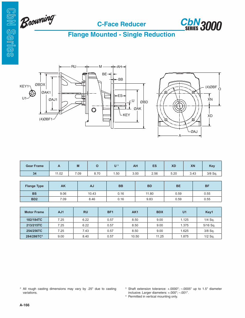
A-166
3000SERIESCbN
CbN
Serie
s
C-Face Reducer
Flange Mounted - Single Reduction
2 variations.
3
4 Permitted in vertical mounting only.
KEY1
(4)ØBF1
A
ES
AH
BB
BE
ØAK
ØBDU
KEY
XN
ØAJ
(4)ØBF
MRU
XD
O
ØAJ1
ØBDX
U1
ØAK1
Gear Frame A M O U 3 AH ES XD XN Key
34 11.02 7.09 8.70 1.50 3.00 2.56 5.20 3.43 3/8 Sq.
Flange Type AK AJ BB BD BE BF
BS 9.06 10.43 0.16 11.80 0.59 0.55
BD2 7.09 8.46 0.16 9.83 0.59 0.55
Motor Frame AJ1 RU BF1 AK1 BDX U1 Key1
182/184TC 7.25 6.22 0.57 8.50 9.00 1.125 1/4 Sq.
213/215TC 7.25 6.22 0.57 8.50 9.00 1.375 5/16 Sq.
254/256TC 7.25 7.43 0.57 8.50 9.00 1.625 3/8 Sq.
284/286TC4 9.00 8.40 0.57 10.50 11.25 1.875 1/2 Sq.

A-167
3000SERIESCbN
CbN
Serie
sC-Face Reducer
Flange Mounted - Single Reduction
2 variations.
3
4 Permitted in vertical mounting only.
KEY1
(4)ØBF1
A
ES
AH
BB
BE
ØAK
ØBDU
KEY
XN
ØAJ
(4)ØBF
MRU
XD
O
ØAJ1
ØBDX
U1
ØAK1
Gear Frame A M O U 3 AH ES XD XN Key
35 13.65 7.89 11.07 1.75 3.50 3.06 6.30 4.33 3/8 Sq.
Flange Type AK AJ BB BD BE BF
BS 9.84 11.81 0.20 13.78 0.71 0.71
BD2 9.06 10.43 0.20 11.81 0.71 0.55
Motor Frame AJ1 RU BF1 AK1 BDX U1 Key1
213/215TC 7.25 5.87 0.57 8.50 9.00 1.375 5/16 Sq.
254/256TC 7.25 7.09 0.57 8.50 9.00 1.625 3/8 Sq.
284/286TC 9.00 8.06 0.57 10.50 11.25 1.875 1/2 Sq.
324/326TC 4 11.00 8.79 0.69 12.50 13.38 2.125 1/2 Sq.
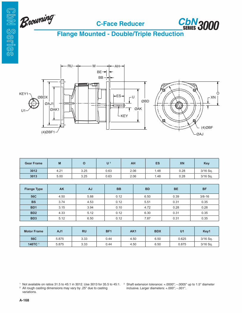
A-168
3000SERIESCbN
CbN
Serie
s
RU M AH
BB
BE
ES U
ØAK
ØBD
ØAJ
XNO
ØAJ1
ØAK1
ØBDX
(4)ØBF1
U1
KEY1
KEY
(4)ØBF
C-Face Reducer
Flange Mounted - Double/Triple Reduction
1 Not available on ratios 31.5 to 45:1 in 3012. Use 3013 for 35.5 to 45:1.2
variations.
3
Gear Frame M O U 3 AH ES XN Key
3012 4.21 3.25 0.63 2.06 1.48 0.28 3/16 Sq.
3013 5.00 3.25 0.63 2.06 1.48 0.28 3/16 Sq.
Flange Type AK AJ BB BD BE BF
56C 4.50 5.88 0.12 6.50 0.39 3/8-16
BS 3.74 4.53 0.12 5.51 0.31 0.35
BD1 3.15 3.94 0.10 4.72 0.28 0.28
BD2 4.33 5.12 0.12 6.30 0.31 0.35
BD3 5.12 6.50 0.12 7.87 0.31 0.35
Motor Frame AJ1 RU BF1 AK1 BDX U1 Key1
56C 5.875 3.33 0.44 4.50 6.50 0.625 3/16 Sq.
140TC 1 5.875 3.33 0.44 4.50 6.50 0.875 3/16 Sq.
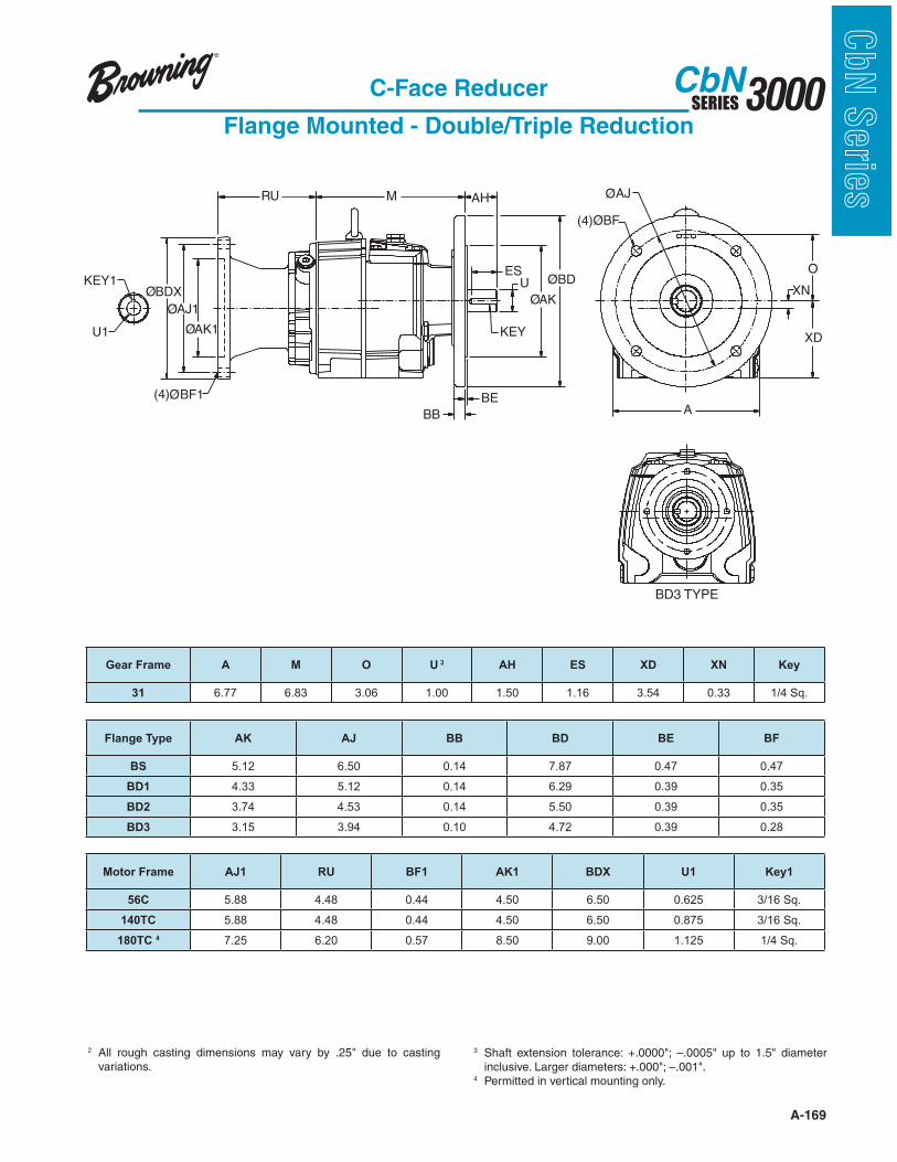
A-169
3000SERIESCbN
CbN
Serie
s
A
(4)ØBF
UES
AHM
KEY
ØBD
ØAK
BE
BB
ØAJ
XN
RU
XD
O
ØAJ1
ØBDX
(4)ØBF1
U1
KEY1
ØAK1
C-Face Reducer
Flange Mounted - Double/Triple Reduction
2 variations.
3
4 Permitted in vertical mounting only.
BD3 TYPE
Gear Frame A M O U 3 AH ES XD XN Key
31 6.77 6.83 3.06 1.00 1.50 1.16 3.54 0.33 1/4 Sq.
Flange Type AK AJ BB BD BE BF
BS 5.12 6.50 0.14 7.87 0.47 0.47
BD1 4.33 5.12 0.14 6.29 0.39 0.35
BD2 3.74 4.53 0.14 5.50 0.39 0.35
BD3 3.15 3.94 0.10 4.72 0.39 0.28
Motor Frame AJ1 RU BF1 AK1 BDX U1 Key1
56C 5.88 4.48 0.44 4.50 6.50 0.625 3/16 Sq.
140TC 5.88 4.48 0.44 4.50 6.50 0.875 3/16 Sq.
180TC 4 7.25 6.20 0.57 8.50 9.00 1.125 1/4 Sq.
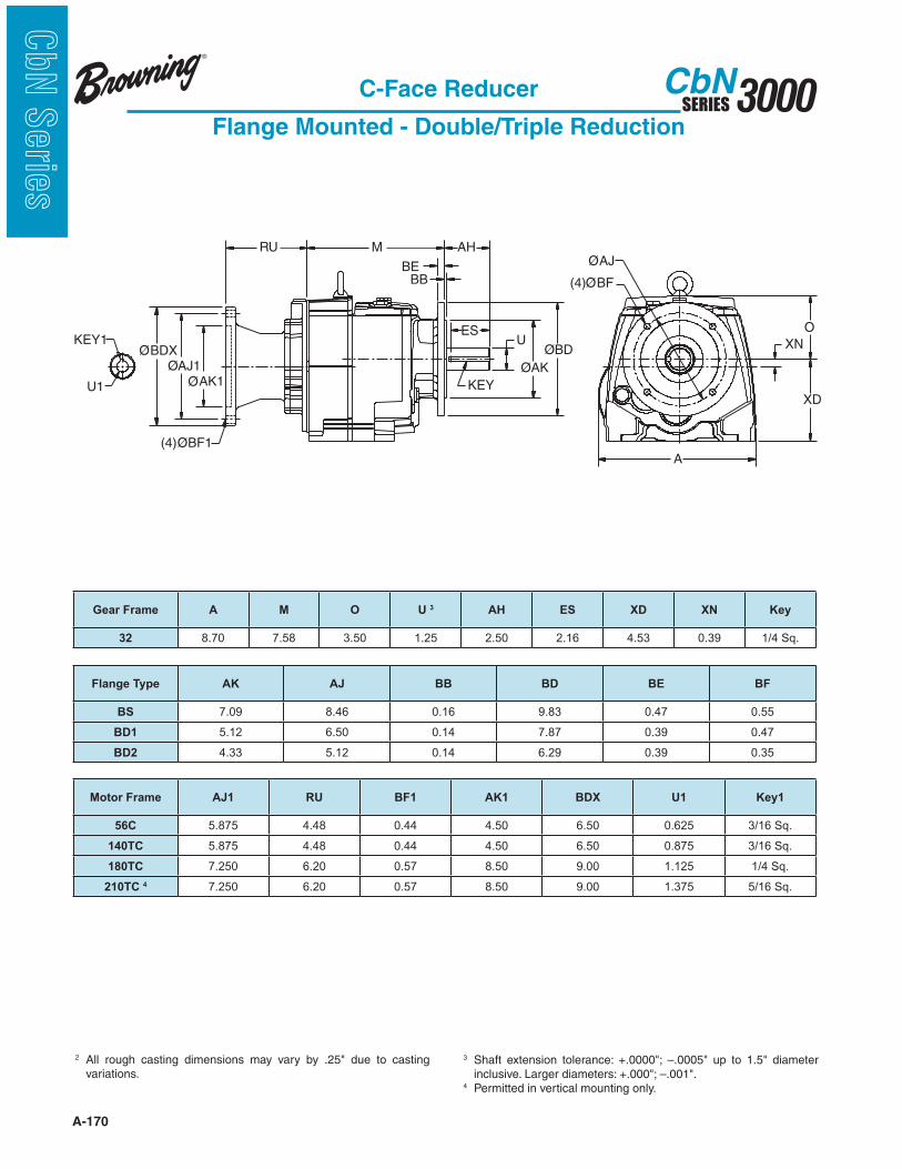
A-170
3000SERIESCbN
CbN
Serie
s
RU M AH
BBBE
ESU
KEY
ØAK
ØBD XN
XD
O
U1 ØAK1
ØBDXØAJ1
KEY1
(4)ØBF1
ØAJ
(4)ØBF
A
C-Face Reducer
Flange Mounted - Double/Triple Reduction
2 variations.
3
4 Permitted in vertical mounting only.
Gear Frame A M O U 3 AH ES XD XN Key
32 8.70 7.58 3.50 1.25 2.50 2.16 4.53 0.39 1/4 Sq.
Flange Type AK AJ BB BD BE BF
BS 7.09 8.46 0.16 9.83 0.47 0.55
BD1 5.12 6.50 0.14 7.87 0.39 0.47
BD2 4.33 5.12 0.14 6.29 0.39 0.35
Motor Frame AJ1 RU BF1 AK1 BDX U1 Key1
56C 5.875 4.48 0.44 4.50 6.50 0.625 3/16 Sq.
140TC 5.875 4.48 0.44 4.50 6.50 0.875 3/16 Sq.
180TC 7.250 6.20 0.57 8.50 9.00 1.125 1/4 Sq.
210TC 4 7.250 6.20 0.57 8.50 9.00 1.375 5/16 Sq.
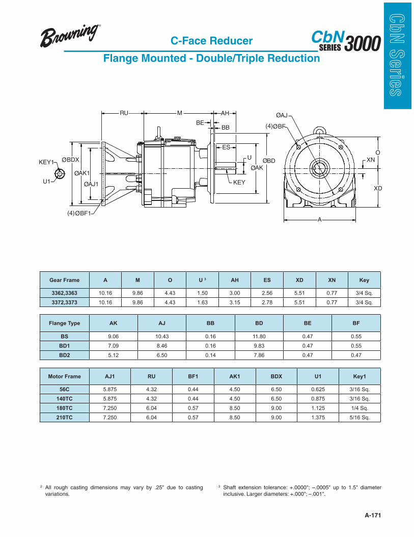
A-171
3000SERIESCbN
CbN
Serie
s
A
RU M AH
BBBE
ES
U
KEY
ØAKØBD
ØAJ
(4)ØBF
XN
XD
O
U1 ØAJ1
ØBDX
ØAK1
(4)ØBF1
KEY1
C-Face Reducer
Flange Mounted - Double/Triple Reduction
2 variations.
3
Gear Frame A M O U 3 AH ES XD XN Key
3362,3363 10.16 9.86 4.43 1.50 3.00 2.56 5.51 0.77 3/4 Sq.
3372,3373 10.16 9.86 4.43 1.63 3.15 2.78 5.51 0.77 3/4 Sq.
Flange Type AK AJ BB BD BE BF
BS 9.06 10.43 0.16 11.80 0.47 0.55
BD1 7.09 8.46 0.16 9.83 0.47 0.55
BD2 5.12 6.50 0.14 7.86 0.47 0.47
Motor Frame AJ1 RU BF1 AK1 BDX U1 Key1
56C 5.875 4.32 0.44 4.50 6.50 0.625 3/16 Sq.
140TC 5.875 4.32 0.44 4.50 6.50 0.875 3/16 Sq.
180TC 7.250 6.04 0.57 8.50 9.00 1.125 1/4 Sq.
210TC 7.250 6.04 0.57 8.50 9.00 1.375 5/16 Sq.

A-172
3000SERIESCbN
CbN
Serie
s
RU M AH
BBBE
ESU
KEY
ØAK
ØBD XN
XD
O
U1 ØAK1
ØBDXØAJ1
KEY1
(4)ØBF1
ØAJ
(4)ØBF
A
C-Face Reducer
Flange Mounted - Double/Triple Reduction
2 variations.
3
4 Permitted in vertical mounting only.
Gear Frame A M O U 3 AH ES XD XN Key
34 11.97 10.63 4.80 2.13 3.50 3.06 7.09 1.02 1/2 Sq.
Flange Type AK AJ BB BD BE BF
BS 9.84 11.81 0.16 13.77 0.59 0.71
BD1 9.06 10.43 0.16 11.80 0.59 0.55
BD2 7.09 8.46 0.16 9.83 0.59 0.55
Motor Frame AJ1 RU BF1 AK1 BDX U1 Key1
56C 5.875 4.50 0.44 4.50 6.50 0.625 3/16 Sq.
143/145TC 5.875 4.50 0.44 4.50 6.50 0.875 3/16 Sq.
182/184TC 7.250 6.22 0.57 8.50 9.00 1.125 1/4 Sq.
213/215TC 7.250 6.22 0.57 8.50 9.00 1.375 5/16 Sq.
254/256TC 7.250 7.43 0.57 8.50 9.00 1.625 3/8 Sq.
284/286TC 4 9.000 8.40 0.57 10.50 11.25 1.875 1/2 Sq.
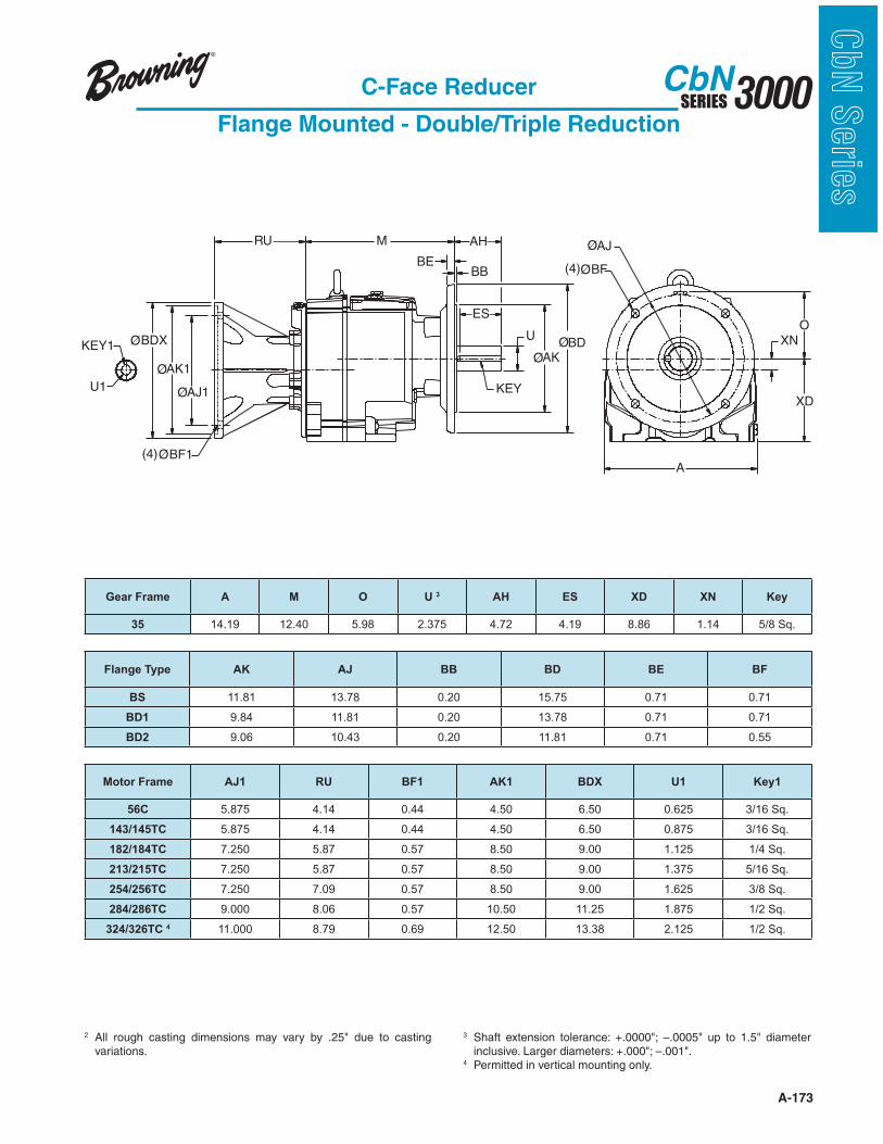
A-173
3000SERIESCbN
CbN
Serie
s
A
RU M AH
BBBE
ES
U
KEY
ØAKØBD
ØAJ
(4)ØBF
XN
XD
O
U1 ØAJ1
ØBDX
ØAK1
(4)ØBF1
KEY1
C-Face Reducer
Flange Mounted - Double/Triple Reduction
2 variations.
3
4 Permitted in vertical mounting only.
Gear Frame A M O U 3 AH ES XD XN Key
35 14.19 12.40 5.98 2.375 4.72 4.19 8.86 1.14 5/8 Sq.
Flange Type AK AJ BB BD BE BF
BS 11.81 13.78 0.20 15.75 0.71 0.71
BD1 9.84 11.81 0.20 13.78 0.71 0.71
BD2 9.06 10.43 0.20 11.81 0.71 0.55
Motor Frame AJ1 RU BF1 AK1 BDX U1 Key1
56C 5.875 4.14 0.44 4.50 6.50 0.625 3/16 Sq.
143/145TC 5.875 4.14 0.44 4.50 6.50 0.875 3/16 Sq.
182/184TC 7.250 5.87 0.57 8.50 9.00 1.125 1/4 Sq.
213/215TC 7.250 5.87 0.57 8.50 9.00 1.375 5/16 Sq.
254/256TC 7.250 7.09 0.57 8.50 9.00 1.625 3/8 Sq.
284/286TC 9.000 8.06 0.57 10.50 11.25 1.875 1/2 Sq.
324/326TC 4 11.000 8.79 0.69 12.50 13.38 2.125 1/2 Sq.
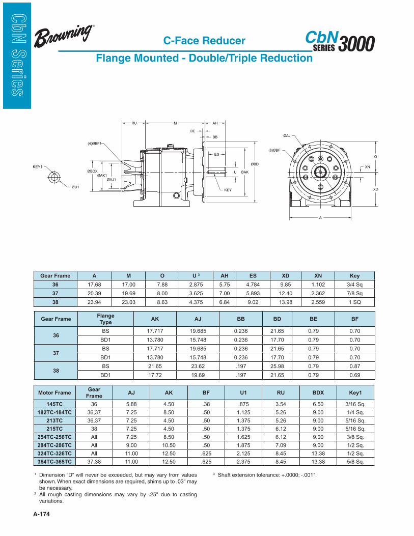
A-174
3000SERIESCbN
CbN
Serie
s
C-Face Reducer
Flange Mounted - Double/Triple Reduction
XN
ES
U
BE
AH
BB
KEY
O
XD
MRU
(4)ØBF1
ØBDXØAK1
ØAJ1
KEY1
ØU1
ØAJ
(8)ØBF
A
ØAK
ØBD
Gear Frame A M O U 3 AH ES XD XN Key
36 17.68 17.00 7.88 2.875 5.75 4.784 9.85 1.102 3/4 Sq
37 20.39 19.69 8.00 3.625 7.00 5.893 12.40 2.362 7/8 Sq
38 23.94 23.03 8.63 4.375 6.84 9.02 13.98 2.559 1 SQ
Gear FrameFlange
TypeAK AJ BB BD BE BF
36BS 17.717 19.685 0.236 21.65 0.79 0.70
BD1 13.780 15.748 0.236 17.70 0.79 0.70
37BS 17.717 19.685 0.236 21.65 0.79 0.70
BD1 13.780 15.748 0.236 17.70 0.79 0.70
38BS 21.65 23.62 .197 25.98 0.79 0.87
BD1 17.72 19.69 .197 21.65 0.79 0.69
Motor FrameGear
FrameAJ AK BF U1 RU BDX Key1
145TC 36 5.88 4.50 .38 .875 3.54 6.50 3/16 Sq.
182TC-184TC 36,37 7.25 8.50 .50 1.125 5.26 9.00 1/4 Sq.
213TC 36,37 7.25 4.50 .50 1.375 5.26 9.00 5/16 Sq.
215TC 38 7.25 4.50 .50 1.375 6.12 9.00 5/16 Sq.
254TC-256TC All 7.25 8.50 .50 1.625 6.12 9.00 3/8 Sq.
284TC-286TC All 9.00 10.50 .50 1.875 7.09 9.00 1/2 Sq.
324TC-326TC All 11.00 12.50 .625 2.125 8.45 13.38 1/2 Sq.
364TC-365TC 37,38 11.00 12.50 .625 2.375 8.45 13.38 5/8 Sq.
1 Dimension “D” will never be exceeded, but may vary from values
be necessary.2
variations.
3

A-175
3000SERIESCbN
CbN
Serie
sC-Face Reducer
Flange Mounted - Combined Reduction
2 variations.
3
RU M AH
BBBE
ES
U
KEY
ØAKØBD
A
ØAJ(4)ØBF
XN
XD
O
ØAJ1
ØAK1
ØBDX
U1
KEY1
(4)ØBF1
Gear Frame A M O U 3 AH ES XD XN Key
3254,3255 8.70 7.58 3.50 1.25 2.50 2.16 4.53 0.12 1/4 Sq.
3374,3375 10.16 9.86 4.43 1.63 3.15 2.78 5.51 0.49 3/8 Sq.
Flange Type32 33
AK AJ BB BD BE BF AK AJ BB BD BE BF
BS 7.09 8.46 0.16 9.83 0.47 0.55 9.06 10.43 0.16 11.80 0.47 0.55
BD1 5.12 6.50 0.14 7.87 0.39 0.47 7.09 8.46 0.16 9.83 0.47 0.55
BD2 4.33 5.12 0.14 6.29 0.39 0.35 5.12 6.50 0.14 7.86 0.47 0.47
Motor Frame RU AJ1 BF1 AK1 BDX U1 Key1
56C 7.79 5.875 0.44 4.50 6.50 0.625 3/16 Sq.
140TC 7.79 5.875 0.44 4.50 6.50 0.875 3/16 Sq.
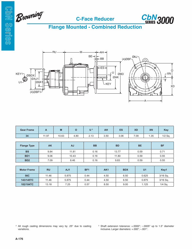
A-176
3000SERIESCbN
CbN
Serie
s
C-Face Reducer
Flange Mounted - Combined Reduction
2 variations.
3
RU M AH
BBBE
ES
U
KEY
ØAKØBD
A
ØAJ(4)ØBF
XN
XD
O
ØAJ1
ØAK1
ØBDX
U1
KEY1
(4)ØBF1
Gear Frame A M O U 3 AH ES XD XN Key
34 11.97 10.63 4.80 2.13 3.50 3.06 7.09 1.35 1/2 Sq.
Flange Type AK AJ BB BD BE BF
BS 9.84 11.81 0.16 13.77 0.59 0.71
BD1 9.06 10.43 0.16 11.80 0.59 0.55
BD2 7.09 8.46 0.16 9.83 0.59 0.55
Motor Frame RU AJ1 BF1 AK1 BDX U1 Key1
56C 11.46 5.875 0.44 4.50 6.50 0.625 3/16 Sq.
143/145TC 11.46 5.875 0.44 4.50 6.50 0.875 3/16 Sq.
182/184TC 13.18 7.25 0.57 8.50 9.00 1.125 1/4 Sq.
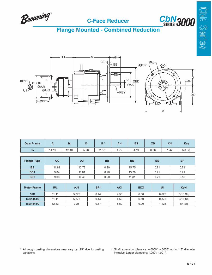
A-177
3000SERIESCbN
CbN
Serie
sC-Face Reducer
Flange Mounted - Combined Reduction
2 variations.
3
RU M AH
BBBE
ES
U
KEY
ØAKØBD
A
ØAJ(4)ØBF
XN
XD
O
ØAJ1
ØAK1
ØBDX
U1
KEY1
(4)ØBF1
Gear Frame A M O U 3 AH ES XD XN Key
35 14.19 12.40 5.98 2.375 4.72 4.19 8.86 1.47 5/8 Sq.
Flange Type AK AJ BB BD BE BF
BS 11.81 13.78 0.20 15.75 0.71 0.71
BD1 9.84 11.81 0.20 13.78 0.71 0.71
BD2 9.06 10.43 0.20 11.81 0.71 0.55
Motor Frame RU AJ1 BF1 AK1 BDX U1 Key1
56C 11.11 5.875 0.44 4.50 6.50 0.625 3/16 Sq.
143/145TC 11.11 5.875 0.44 4.50 6.50 0.875 3/16 Sq.
182/184TC 12.83 7.25 0.57 8.50 9.00 1.125 1/4 Sq.
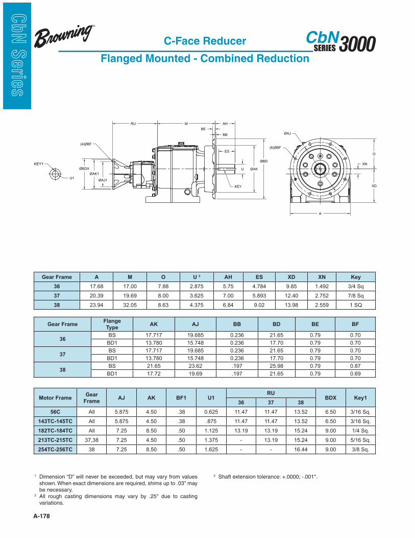
A-178
3000SERIESCbN
CbN
Serie
s
C-Face Reducer
Flanged Mounted - Combined Reduction
ES
U
KEY
ØAK
ØBD
BE
AH
BB
XN
O
XD
ØAK1
ØAJ1
RU
(4)ØBF
U1
KEY1
ØBDX
M
ØAJ
(8)ØBF
A
Gear Frame A M O U 3 AH ES XD XN Key
36 17.68 17.00 7.88 2.875 5.75 4.784 9.85 1.492 3/4 Sq
37 20.39 19.69 8.00 3.625 7.00 5.893 12.40 2.752 7/8 Sq
38 23.94 32.05 8.63 4.375 6.84 9.02 13.98 2.559 1 SQ
Gear FrameFlange
TypeAK AJ BB BD BE BF
36BS 17.717 19.685 0.236 21.65 0.79 0.70
BD1 13.780 15.748 0.236 17.70 0.79 0.70
37BS 17.717 19.685 0.236 21.65 0.79 0.70
BD1 13.780 15.748 0.236 17.70 0.79 0.70
38BS 21.65 23.62 .197 25.98 0.79 0.87
BD1 17.72 19.69 .197 21.65 0.79 0.69
Motor FrameGear
FrameAJ AK BF1 U1
RUBDX Key1
36 37 38
56C All 5.875 4.50 .38 0.625 11.47 11.47 13.52 6.50 3/16 Sq.
143TC-145TC All 5.875 4.50 .38 .875 11.47 11.47 13.52 6.50 3/16 Sq.
182TC-184TC All 7.25 8.50 .50 1.125 13.19 13.19 15.24 9.00 1/4 Sq.
213TC-215TC 37,38 7.25 4.50 .50 1.375 - 13.19 15.24 9.00 5/16 Sq.
254TC-256TC 38 7.25 8.50 .50 1.625 - - 16.44 9.00 3/8 Sq.
1 Dimension “D” will never be exceeded, but may vary from values
be necessary.2
variations.
3
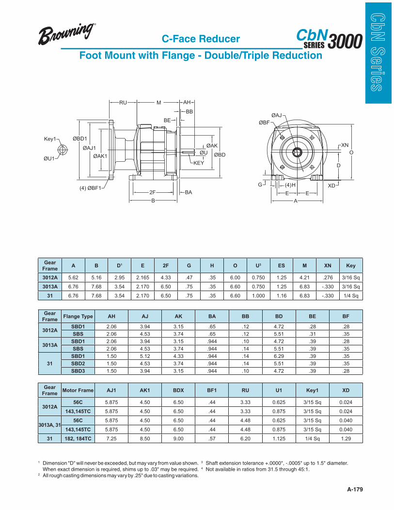
A-179
3000SERIESCbN
CbN
Serie
sC-Face Reducer
Foot Mount with Flange - Double/Triple Reduction
1
2
3 4 Not available in ratios from 31.5 through 45:1.
Gear
FrameMotor Frame AJ1 AK1 BDX BF1 RU U1 Key1 XD
3012A56C 5.875 4.50 6.50 .44 3.33 0.625 3/15 Sq 0.024
143,145TC 5.875 4.50 6.50 .44 3.33 0.875 3/15 Sq 0.024
3013A, 3156C 5.875 4.50 6.50 .44 4.48 0.625 3/15 Sq 0.040
143,145TC 5.875 4.50 6.50 .44 4.48 0.875 3/15 Sq 0.040
31 182, 184TC 7.25 8.50 9.00 .57 6.20 1.125 1/4 Sq 1.29
Gear
FrameFlange Type AH AJ AK BA BB BD BE BF
3012ASBD1 2.06 3.94 3.15 .65 .12 4.72 .28 .28
SBS 2.06 4.53 3.74 .65 .12 5.51 .31 .35
3013ASBD1 2.06 3.94 3.15 .944 .10 4.72 .39 .28
SBS 2.06 4.53 3.74 .944 .14 5.51 .39 .35
31
SBD1 1.50 5.12 4.33 .944 .14 6.29 .39 .35
SBD2 1.50 4.53 3.74 .944 .14 5.51 .39 .35
SBD3 1.50 3.94 3.15 .944 .10 4.72 .39 .28
Gear
FrameA B D1 E 2F G H O U3 ES M XN Key
3012A 5.62 5.16 2.95 2.165 4.33 .47 .35 6.00 0.750 1.25 4.21 .276 3/16 Sq
3013A 6.76 7.68 3.54 2.170 6.50 .75 .35 6.60 0.750 1.25 6.83 -.330 3/16 Sq
31 6.76 7.68 3.54 2.170 6.50 .75 .35 6.60 1.000 1.16 6.83 -.330 1/4 Sq
A
XN
D
EE
O
XD(4) HG
ØAJ
ØBF
2F
B
RU M
BE
BB
AH
KEY
BA
ØU
ØAK
ØBDØAK1
ØAJ1
ØBD1
(4) ØBF1
Key1
ØU1
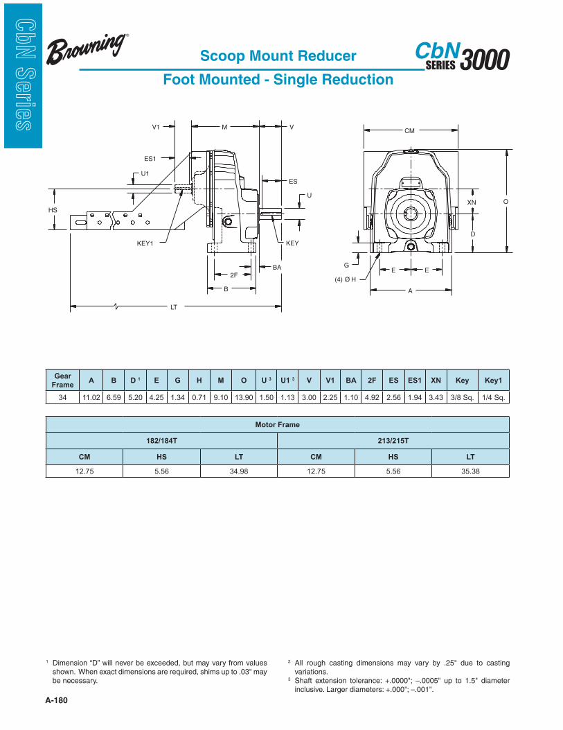
A-180
3000SERIESCbN
CbN
Serie
s
Scoop Mount Reducer
Foot Mounted - Single Reduction
1 Dimension “D” will never be exceeded, but may vary from values
be necessary.
2 variations.
3
(4) Ø H
KEY
ES1
V1
U1
KEY1
HS
LT
BA
CM
O
M V
ES
U
2F
B
XN
D
E
A
EG
Gear
FrameA B D 1 E G H M O U 3 U1 3 V V1 BA 2F ES ES1 XN Key Key1
34 11.02 6.59 5.20 4.25 1.34 0.71 9.10 13.90 1.50 1.13 3.00 2.25 1.10 4.92 2.56 1.94 3.43 3/8 Sq. 1/4 Sq.
Motor Frame
182/184T 213/215T
CM HS LT CM HS LT
12.75 5.56 34.98 12.75 5.56 35.38
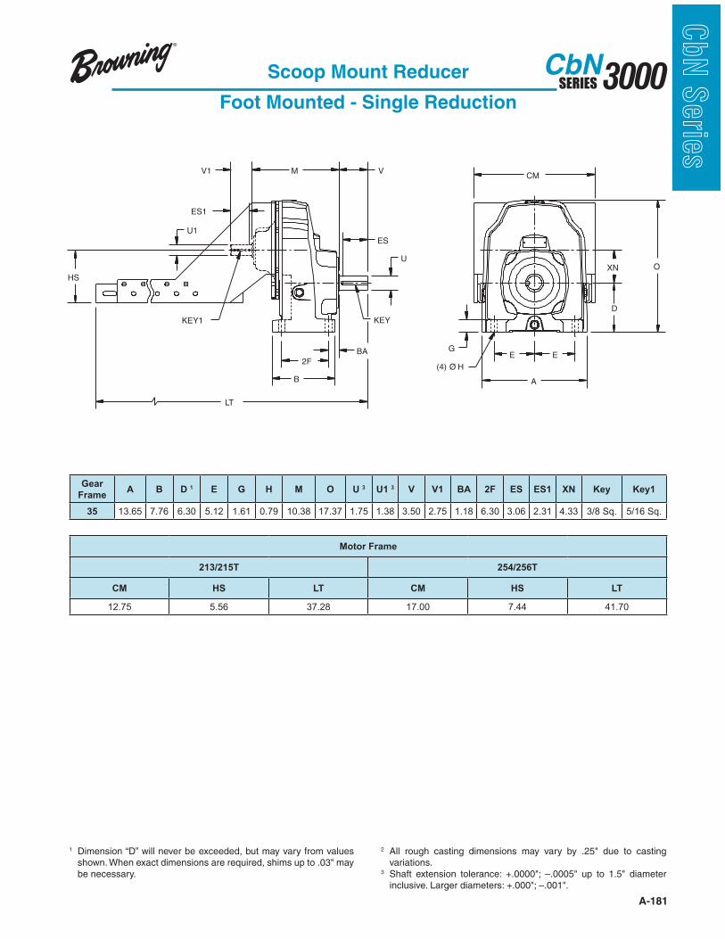
A-181
3000SERIESCbN
CbN
Serie
sScoop Mount Reducer
Foot Mounted - Single Reduction
1 Dimension “D” will never be exceeded, but may vary from values
be necessary.
2 variations.
3
(4) Ø H
KEY
ES1
V1
U1
KEY1
HS
LT
BA
CM
O
M V
ES
U
2F
B
XN
D
E
A
EG
Gear
FrameA B D 1 E G H M O U 3 U1 3 V V1 BA 2F ES ES1 XN Key Key1
35 13.65 7.76 6.30 5.12 1.61 0.79 10.38 17.37 1.75 1.38 3.50 2.75 1.18 6.30 3.06 2.31 4.33 3/8 Sq. 5/16 Sq.
Motor Frame
213/215T 254/256T
CM HS LT CM HS LT
12.75 5.56 37.28 17.00 7.44 41.70

A-182
3000SERIESCbN
CbN
Serie
s
HS
U1
V1
2FB
LT
M V
U
CM
D
O
XN
A
E E
G
BA
ESES1
KEY1KEY
(4)ØH
Scoop Mount Reducer
Foot Mounted - Double/Triple Reduction
1 Dimension “D” will never be exceeded, but may vary from values
be necessary.
2 variations.
3
Gear
FrameA B D 1 E G H M O U 3 U1 3 V V1 BA 2F ES ES1 XN Key Key1
32 8.72 8.50 4.53 2.66 0.84 0.55 9.11 7.97 1.25 0.63 2.50 1.25 0.51 7.56 2.16 1.00 0.39 1/4 Sq. 3/16 Sq.
3362,3363 10.13 10.72 5.51 3.35 1.07 0.71 11.34 9.94 1.50 1.13 3.00 2.25 0.77 9.45 2.56 1.94 0.77 3/8 Sq. 1/4 Sq.
3372,3373 10.13 10.72 5.51 3.35 1.07 0.71 11.34 9.94 1.63 1.13 3.15 2.25 0.77 9.45 2.78 1.94 0.77 3/8 Sq. 1/4 Sq.
34 11.97 10.87 7.09 4.53 1.37 0.71 12.66 11.89 2.13 1.13 3.50 2.25 0.98 9.25 3.06 1.94 1.02 1/2 Sq. 1/4 Sq.
Gear
Frame
Motor Frame
143/145T 182/184T 213/215T
CM HS LT CM HS LT CM HS LT
32 11.38 3.75 27.97 - - - - - -
3362,3363 12.38 4.74 37.31 12.38 4.74 37.31 - - -
3372,3373 12.38 4.74 37.46 12.38 4.74 37.46 - - -
34 12.75 5.56 40.04 12.75 5.56 39.04 12.75 5.56 39.44
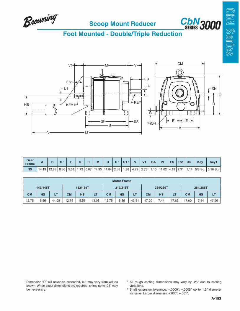
A-183
3000SERIESCbN
CbN
Serie
s
HS
U1
V1
2FB
LT
M V
U
CM
D
O
XN
A
E E
G
BA
ESES1
KEY1KEY
(4)ØH
Scoop Mount Reducer
Foot Mounted - Double/Triple Reduction
1 Dimension “D” will never be exceeded, but may vary from values
be necessary.
2 variations.
3
Gear
FrameA B D 1 E G H M O U 3 U1 3 V V1 BA 2F ES ES1 XN Key Key1
35 14.19 12.89 8.86 5.51 1.73 0.87 14.95 14.84 2.38 1.38 4.72 2.75 1.10 11.02 4.19 2.31 1.14 5/8 Sq. 5/16 Sq.
Motor Frame
143/145T 182/184T 213/215T 254/256T 284/286T
CM HS LT CM HS LT CM HS LT CM HS LT CM HS LT
12.75 5.56 44.08 12.75 5.56 43.08 12.75 5.56 43.41 17.00 7.44 47.83 17.00 7.44 47.96
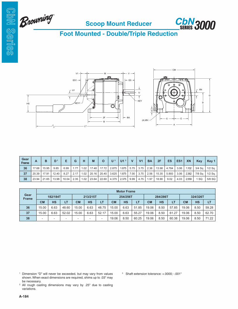
A-184
3000SERIESCbN
CbN
Serie
s
Scoop Mount Reducer
Foot Mounted - Double/Triple Reduction
B
XN
2F BA
V
ES
U
KEYD
O
E E
A
G
(4) ØH
KEY1
LT
CM
MV1
ES1
U1
HS
Gear
FrameA B D 1 E G H M O U 3 U1 3 V V1 BA 2F ES ES1 XN Key Key 1
36 17.68 15.95 9.85 6.99 1.77 1.02 17.48 17.72 2.875 1.875 5.75 3.75 2.36 13.98 4.784 3.06 1.102 3/4 Sq 1/2 Sq.
37 20.39 17.91 12.40 8.27 2.17 1.02 20.16 20.40 3.625 1.875 7.00 3.75 2.56 15.35 5.893 3.06 2.362 7/8 Sq 1/2 Sq.
38 23.94 21.65 13.98 10.04 2.35 1.02 23.64 22.60 4.375 2.375 9.99 4.75 1.97 18.90 9.02 4.03 2.559 1 SQ 5/8 SQ
Gear
Frame
Motor Frame
182/184T 213/215T 254/256T 284/286T 324/326T
CM HS LT CM HS LT CM HS LT CM HS LT CM HS LT
36 15.00 6.63 48.60 15.00 6.63 48.75 15.00 6.63 51.85 19.06 8.50 57.85 19.06 8.50 59.28
37 15.00 6.63 52.02 15.00 6.63 52.17 15.00 6.63 55.27 19.06 8.50 61.27 19.06 8.50 62.70
38 - - - - - - 19.06 8.50 60.25 19.06 8.50 60.38 19.06 8.50 71.22
1 Dimension “D” will never be exceeded, but may vary from values
be necessary.2
variations.
3

A-185
3000SERIESCbN
CbN
Serie
sScoop Mount Reducer
Foot Mounted - Combined Reduction
1 Dimension “D” will never be exceeded, but may vary from values
be necessary.
2 variations.
3
B
E E
A
G
(4) ØH
XN
D
O
2F BA
V
ES
U
KEY
CbN36-37 Combined Reduction - Foot Mounted Scoop Mount Reducer
U1
ES1
V1
KEY1
M
LT
Gear
Frame
Motor Frame
143/145T 182/184T 213/215T
HS LT HS LT HS LT
36 3.75 51.21 - - - -
37 3.75 55.14 - - - -
38 5.56 63.03 5.56 62.03 5.56 62.16
Gear
FrameA B D 1 E G H M O U 3 U1 3 V V1 BA 2F ES ES1 XN Key Key 1
36 17.68 15.95 9.85 6.99 1.77 1.02 22.73 17.72 2.875 0.63 5.75 1.25 2.36 13.98 4.784 1.00 1.492 3/4 Sq 3/16 Sq.
37 20.39 17.91 12.40 8.27 2.17 1.02 25.40 20.40 3.625 0.63 7.00 1.25 2.56 15.35 5.893 1.00 2.752 7/8 Sq 3/16 Sq.
38 23.94 21.65 13.98 10.04 2.35 1.02 23.64 22.60 4.375 2.375 9.99 5.56 1.97 18.90 9.02 5.00 2.559 1 SQ 5/8 SQ
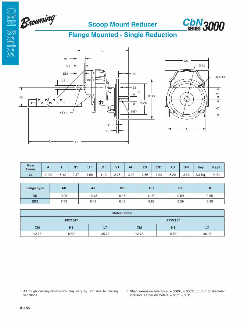
A-186
3000SERIESCbN
CbN
Serie
s
Scoop Mount Reducer
Flange Mounted - Single Reduction
2 variations.
3
A
XN
CM
XD
(4) Ø BF
Ø AJ
LT
HS
U1
ES1
V1
KEY1
U
KEY
ES
Ø AK
Ø BD
AH
BE
BB
N1
L
Gear
FrameA L N1 U 3 U1 3 V1 AH ES ES1 XD XN Key Key1
34 11.02 15.12 2.37 1.50 1.13 2.25 3.00 2.56 1.94 5.20 3.43 3/8 Sq. 1/4 Sq.
Flange Type AK AJ BB BD BE BF
BS 9.06 10.43 0.16 11.80 0.59 0.55
BD2 7.09 8.46 0.16 9.83 0.59 0.55
Motor Frame
182/184T 213/215T
CM HS LT CM HS LT
12.75 5.56 35.75 12.75 5.56 36.05
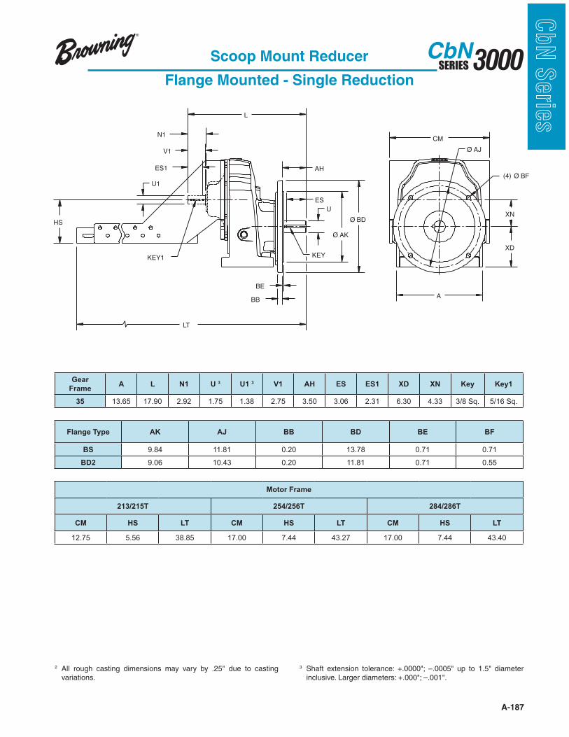
A-187
3000SERIESCbN
CbN
Serie
s
A
XN
CM
XD
(4) Ø BF
Ø AJ
LT
HS
U1
ES1
V1
KEY1
U
KEY
ES
Ø AK
Ø BD
AH
BE
BB
N1
L
Scoop Mount Reducer
Flange Mounted - Single Reduction
2 variations.
3
Gear
FrameA L N1 U 3 U1 3 V1 AH ES ES1 XD XN Key Key1
35 13.65 17.90 2.92 1.75 1.38 2.75 3.50 3.06 2.31 6.30 4.33 3/8 Sq. 5/16 Sq.
Flange Type AK AJ BB BD BE BF
BS 9.84 11.81 0.20 13.78 0.71 0.71
BD2 9.06 10.43 0.20 11.81 0.71 0.55
Motor Frame
213/215T 254/256T 284/286T
CM HS LT CM HS LT CM HS LT
12.75 5.56 38.85 17.00 7.44 43.27 17.00 7.44 43.40

A-188
3000SERIESCbN
CbN
Serie
s
UES
AH
L
ØBD
ØAK
BEBB
(4)ØBF
ØAJ
XNU1
ES1
N1
V1
LT
HS
CM
A
XD
KEY
KEY
Scoop Mount Reducer
Flange Mounted - Double/Triple Reduction
2 variations.
3
Gear
FrameA L N1 U 3 U1 3 V1 AH ES ES1 XD XN Key Key1
32 8.70 13.25 1.29 1.25 0.63 1.25 2.50 2.16 1.00 4.53 0.39 1/4 Sq. 3/16 Sq.
3362,3363 10.16 17.61 2.31 1.50 1.13 2.25 3.00 2.56 1.94 5.51 0.77 3/8 Sq. 1/4 Sq.
3372,3373 10.16 17.76 2.31 1.63 1.13 2.25 3.15 2.78 1.94 5.51 0.77 3/8 Sq. 1/4 Sq.
Flange
Type
32 33
AK AJ BB BD BE BF AK AJ BB BD BE BF
BS 7.09 8.46 0.16 9.83 0.47 0.55 9.06 10.43 0.16 11.80 0.47 0.55
BD1 5.12 6.50 0.14 7.87 0.39 0.47 7.09 8.46 0.16 9.83 0.47 0.55
BD2 4.33 5.12 0.14 6.29 0.39 0.35 5.12 6.50 0.14 7.86 0.47 0.47
Gear
Frame
Motor Frame
143/145T 182/184T
CM HS LT CM HS LT
32 11.38 3.75 28.36 - - -
3362,3363 12.38 4.74 38.33 12.38 4.74 38.33
3372,3373 12.38 4.74 38.48 12.38 4.74 38.48
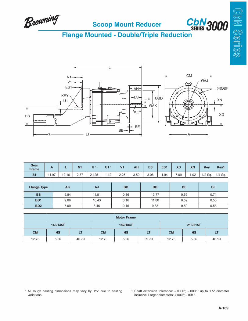
A-189
3000SERIESCbN
CbN
Serie
s
UES
AH
L
ØBD
ØAK
BEBB
(4)ØBF
ØAJ
XNU1
ES1
N1
V1
LT
HS
CM
A
XD
KEY
KEY
Scoop Mount Reducer
Flange Mounted - Double/Triple Reduction
2 variations.
3
Gear
FrameA L N1 U 3 U1 3 V1 AH ES ES1 XD XN Key Key1
34 11.97 19.16 2.37 2.125 1.12 2.25 3.50 3.06 1.94 7.09 1.02 1/2 Sq. 1/4 Sq.
Flange Type AK AJ BB BD BE BF
BS 9.84 11.81 0.16 13.77 0.59 0.71
BD1 9.06 10.43 0.16 11.80 0.59 0.55
BD2 7.09 8.46 0.16 9.83 0.59 0.55
Motor Frame
143/145T 182/184T 213/215T
CM HS LT CM HS LT CM HS LT
12.75 5.56 40.79 12.75 5.56 39.79 12.75 5.56 40.19
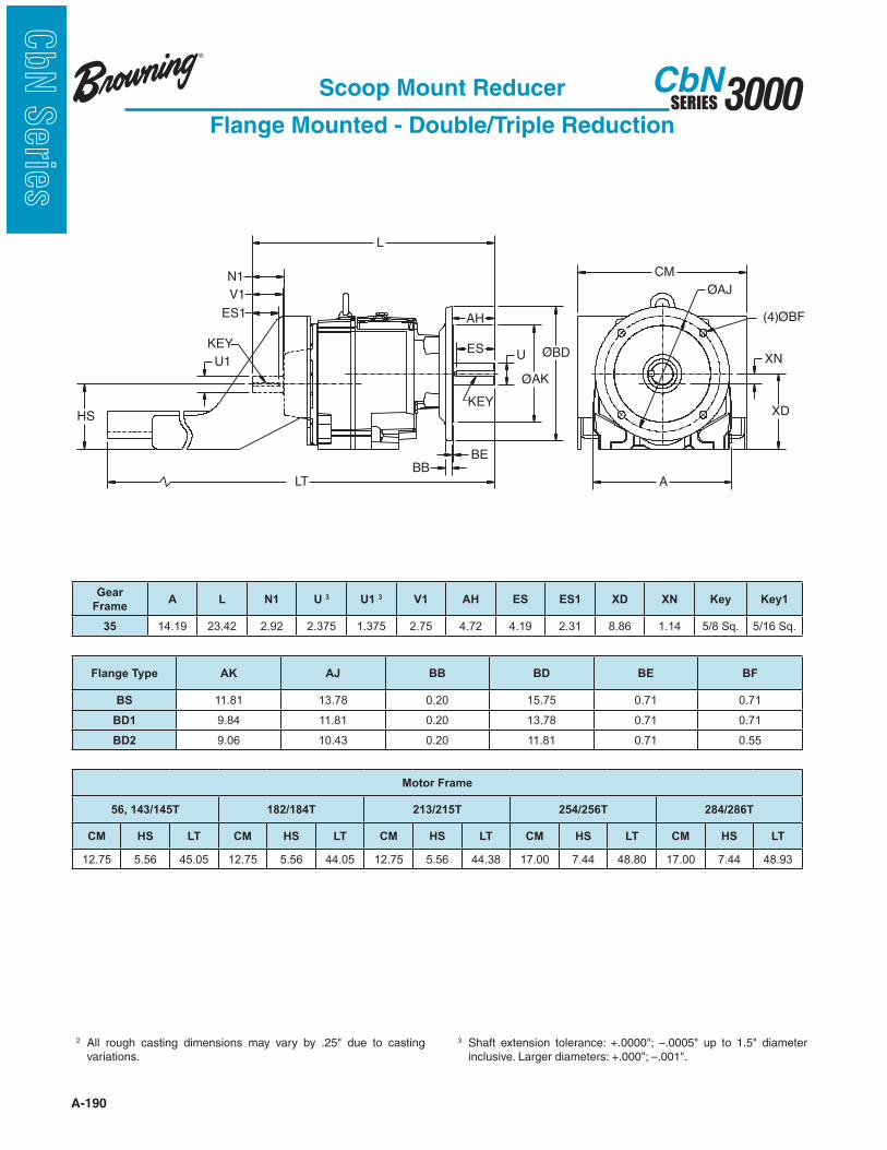
A-190
3000SERIESCbN
CbN
Serie
s
UES
AH
L
ØBD
ØAK
BEBB
(4)ØBF
ØAJ
XNU1
ES1
N1
V1
LT
HS
CM
A
XD
KEY
KEY
Scoop Mount Reducer
Flange Mounted - Double/Triple Reduction
2 variations.
3
Gear
FrameA L N1 U 3 U1 3 V1 AH ES ES1 XD XN Key Key1
35 14.19 23.42 2.92 2.375 1.375 2.75 4.72 4.19 2.31 8.86 1.14 5/8 Sq. 5/16 Sq.
Flange Type AK AJ BB BD BE BF
BS 11.81 13.78 0.20 15.75 0.71 0.71
BD1 9.84 11.81 0.20 13.78 0.71 0.71
BD2 9.06 10.43 0.20 11.81 0.71 0.55
Motor Frame
56, 143/145T 182/184T 213/215T 254/256T 284/286T
CM HS LT CM HS LT CM HS LT CM HS LT CM HS LT
12.75 5.56 45.05 12.75 5.56 44.05 12.75 5.56 44.38 17.00 7.44 48.80 17.00 7.44 48.93
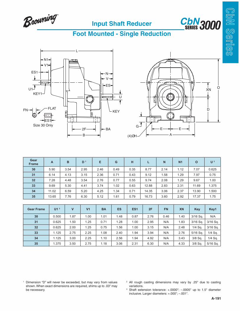
A-191
3000SERIESCbN
CbN
Serie
s
V
V1
BA
(4)ØH
N1
U1
ES1
KEY1
L
ESO
GEE
A
U
KEY
2F
B
D
XN
N
Size 30 Only
FN
ES1
FLAT
Input Shaft Reducer
Foot Mounted - Single Reduction
1 Dimension “D” will never be exceeded, but may vary from values
be necessary.
2 variations.
3
Gear
FrameA B D 1 E G H L N N1 O U 3
30 5.90 3.54 2.95 2.46 0.49 0.35 8.77 2.14 1.12 7.07 0.625
31 6.14 4.13 3.15 2.36 0.71 0.43 9.12 1.58 1.29 7.97 0.75
32 7.28 4.48 3.54 2.76 0.77 0.55 9.74 2.08 1.29 9.67 1.00
33 9.69 5.30 4.41 3.74 1.02 0.63 12.88 2.83 2.31 11.69 1.375
34 11.02 6.59 5.20 4.25 1.34 0.71 14.35 3.06 2.37 13.90 1.500
35 13.65 7.76 6.30 5.12 1.61 0.79 16.73 3.60 2.92 17.37 1.75
Gear Frame U1 3 V V1 BA ES ES1 2F FN XN Key Key1
30 0.500 1.87 1.00 1.01 1.48 0.87 2.76 0.46 1.40 3/16 Sq. N/A
31 0.625 1.50 1.25 0.71 1.28 1.00 2.95 N/A 1.83 3/16 Sq. 3/16 Sq.
32 0.625 2.00 1.25 0.75 1.56 1.00 3.15 N/A 2.48 1/4 Sq. 3/16 Sq.
33 1.125 2.75 2.25 1.08 2.40 1.94 3.94 N/A 2.76 5/16 Sq. 1/4 Sq.
34 1.125 3.00 2.25 1.10 2.56 1.94 4.92 N/A 3.43 3/8 Sq. 1/4 Sq.
35 1.375 3.50 2.75 1.18 3.06 2.31 6.30 N/A 4.33 3/8 Sq. 5/16 Sq.
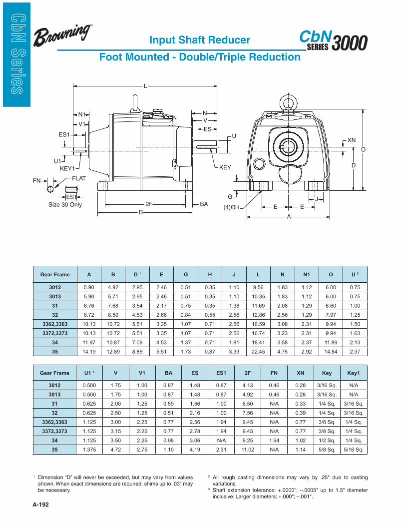
A-192
3000SERIESCbN
CbN
Serie
s
KEYU1
ES1
KEY1
N1
O
BA
V1
FN
Size 30 Only
ES1
V
ES
N
L
2F
B
G
XN
D
U
E E
A
J
(4)ØH
FLAT
Input Shaft Reducer
Foot Mounted - Double/Triple Reduction
1 Dimension “D” will never be exceeded, but may vary from values
be necessary.
2 variations.
3
Gear Frame A B D 1 E G H J L N N1 O U 3
3012 5.90 4.92 2.95 2.46 0.51 0.35 1.10 9.56 1.83 1.12 6.00 0.75
3013 5.90 5.71 2.95 2.46 0.51 0.35 1.10 10.35 1.83 1.12 6.00 0.75
31 6.76 7.68 3.54 2.17 0.75 0.35 1.38 11.69 2.08 1.29 6.60 1.00
32 8.72 8.50 4.53 2.66 0.84 0.55 2.56 12.86 2.56 1.29 7.97 1.25
3362,3363 10.13 10.72 5.51 3.35 1.07 0.71 2.56 16.59 3.08 2.31 9.94 1.50
3372,3373 10.13 10.72 5.51 3.35 1.07 0.71 2.56 16.74 3.23 2.31 9.94 1.63
34 11.97 10.87 7.09 4.53 1.37 0.71 1.81 18.41 3.58 2.37 11.89 2.13
35 14.19 12.89 8.86 5.51 1.73 0.87 3.33 22.45 4.75 2.92 14.84 2.37
Gear Frame U1 3 V V1 BA ES ES1 2F FN XN Key Key1
3012 0.500 1.75 1.00 0.87 1.48 0.87 4.13 0.46 0.28 3/16 Sq. N/A
3013 0.500 1.75 1.00 0.87 1.48 0.87 4.92 0.46 0.28 3/16 Sq. N/A
31 0.625 2.00 1.25 0.59 1.56 1.00 6.50 N/A 0.33 1/4 Sq. 3/16 Sq.
32 0.625 2.50 1.25 0.51 2.16 1.00 7.56 N/A 0.39 1/4 Sq. 3/16 Sq.
3362,3363 1.125 3.00 2.25 0.77 2.56 1.94 9.45 N/A 0.77 3/8 Sq. 1/4 Sq.
3372,3373 1.125 3.15 2.25 0.77 2.78 1.94 9.45 N/A 0.77 3/8 Sq. 1/4 Sq.
34 1.125 3.50 2.25 0.98 3.06 N/A 9.25 1.94 1.02 1/2 Sq. 1/4 Sq.
35 1.375 4.72 2.75 1.10 4.19 2.31 11.02 N/A 1.14 5/8 Sq. 5/16 Sq.
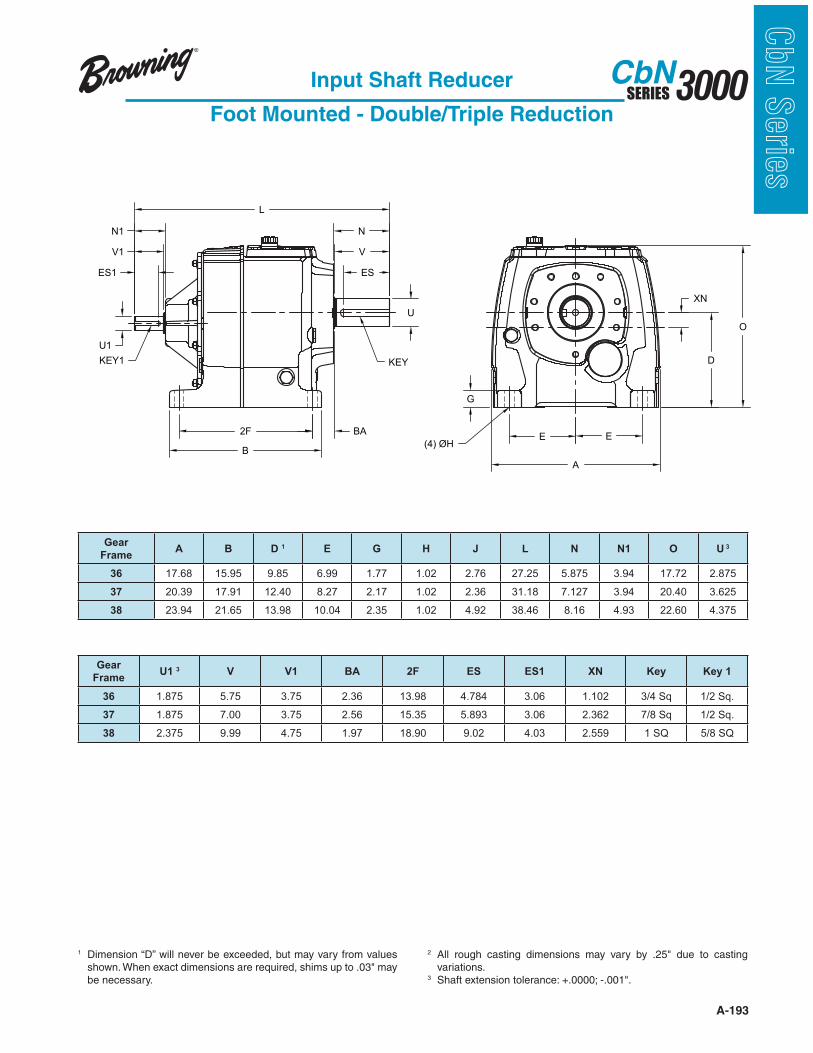
A-193
3000SERIESCbN
CbN
Serie
sInput Shaft Reducer
Foot Mounted - Double/Triple Reduction
1 Dimension “D” will never be exceeded, but may vary from values
be necessary.
2 variations.
3
Gear
FrameA B D 1 E G H J L N N1 O U 3
36 17.68 15.95 9.85 6.99 1.77 1.02 2.76 27.25 5.875 3.94 17.72 2.875
37 20.39 17.91 12.40 8.27 2.17 1.02 2.36 31.18 7.127 3.94 20.40 3.625
38 23.94 21.65 13.98 10.04 2.35 1.02 4.92 38.46 8.16 4.93 22.60 4.375
Gear
FrameU1 3 V V1 BA 2F ES ES1 XN Key Key 1
36 1.875 5.75 3.75 2.36 13.98 4.784 3.06 1.102 3/4 Sq 1/2 Sq.
37 1.875 7.00 3.75 2.56 15.35 5.893 3.06 2.362 7/8 Sq 1/2 Sq.
38 2.375 9.99 4.75 1.97 18.90 9.02 4.03 2.559 1 SQ 5/8 SQ
B
XN
2F BA
N
V
ES
U
KEY
L
D
O
E E
A
G
(4) ØH
ES1
V1
N1
U1
KEY1

A-194
3000SERIESCbN
CbN
Serie
s
ES
V
N
U
KEY
BA2F
B
G
E E
A
D
XN
O
L
(4)ØH
J
U1
ES1
N1V1
FN
FLAT
Input Shaft Reducer
Foot Mounted - Combined Reduction
1 Dimension “D” will never be exceeded, but may vary from values
be necessary.
2 variations.
3
Gear Frame A B D 1 E G H J L N N1 O
32 8.72 8.50 4.53 2.66 0.84 0.55 2.56 17.73 2.56 1.12 7.97
33 10.13 10.72 5.51 3.35 1.07 0.71 2.56 19.88 3.23 1.12 9.94
Gear Frame U 3 U1 3 V V1 BA 2F FN ES ES1 XN Key
32 1.25 0.50 2.50 1.00 0.51 7.56 0.46 2.16 0.87 0.12 1/4 Sq.
33 1.625 0.50 3.15 1.00 0.77 9.45 0.46 2.78 0.87 0.49 3/8 Sq.

A-195
3000SERIESCbN
CbN
Serie
sInput Shaft Reducer
Foot Mounted - Combined Reduction
1 Dimension “D” will never be exceeded, but may vary from values
be necessary.
2 variations.
3
O
J
EE
A
G
(4) Ø H
U
ES
V
N
KEY
L
BA2F
B
ES1
V1
N1
KEY1
U1 D
XN
Gear Frame A B D 1 E G H J L N N1 O U 3
34 11.97 10.87 7.09 4.53 1.37 0.71 1.81 23.54 3.58 1.29 11.89 2.125
Gear Frame U1 3 V V1 BA 2F ES ES1 XN Key Key1
34 0.625 3.50 1.25 0.98 9.25 3.06 1.00 1.35 1/2 Sq. 3/16 Sq.
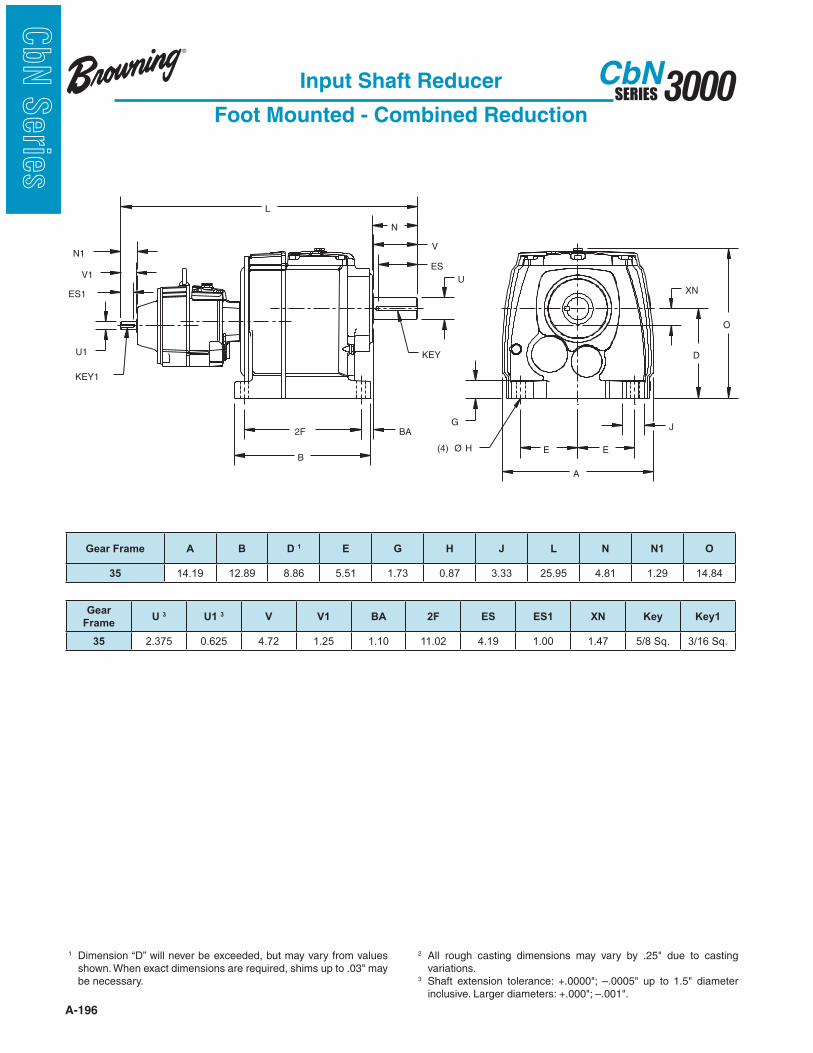
A-196
3000SERIESCbN
CbN
Serie
s
Input Shaft Reducer
Foot Mounted - Combined Reduction
1 Dimension “D” will never be exceeded, but may vary from values
be necessary.
2 variations.
3
O
J
EE
A
G
(4) Ø H
U
ES
V
N
KEY
L
BA2F
B
ES1
V1
N1
KEY1
U1 D
XN
Gear Frame A B D 1 E G H J L N N1 O
35 14.19 12.89 8.86 5.51 1.73 0.87 3.33 25.95 4.81 1.29 14.84
Gear
FrameU 3 U1 3 V V1 BA 2F ES ES1 XN Key Key1
35 2.375 0.625 4.72 1.25 1.10 11.02 4.19 1.00 1.47 5/8 Sq. 3/16 Sq.
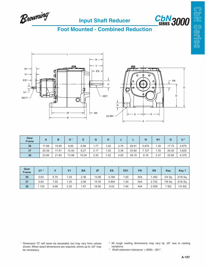
A-197
3000SERIESCbN
CbN
Serie
sInput Shaft Reducer
Foot Mounted - Combined Reduction
1 Dimension “D” will never be exceeded, but may vary from values
be necessary.
2 variations.
3
B
E E
A
G
(4) ØH
XN
D
O
2F BA
N
V
ES
U
KEY
U1
ES1
V1
N1
L
KEY1
Gear
FrameA B D 1 E G H J L N N1 O U 3
36 17.68 15.95 9.85 6.99 1.77 1.02 2.76 29.91 5.875 1.35 17.72 2.875
37 20.39 17.91 12.40 8.27 2.17 1.02 2.36 33.84 7.127 1.35 20.40 3.625
38 23.94 21.65 13.98 10.04 2.35 1.02 4.92 39.19 8.16 2.37 22.60 4.375
Gear
FrameU1 3 V V1 BA 2F ES ES1 FN XN Key Key 1
36 0.63 5.75 1.25 2.36 13.98 4.784 1.00 N/A 1.492 3/4 Sq 3/16 Sq.
37 0.63 7.00 1.25 2.56 15.35 5.893 1.00 N/A 2.752 7/8 Sq 3/16 Sq.
38 1.125 9.99 2.25 1.97 18.90 9.02 1.94 N/A 2.559 1 SQ 1/4 SQ
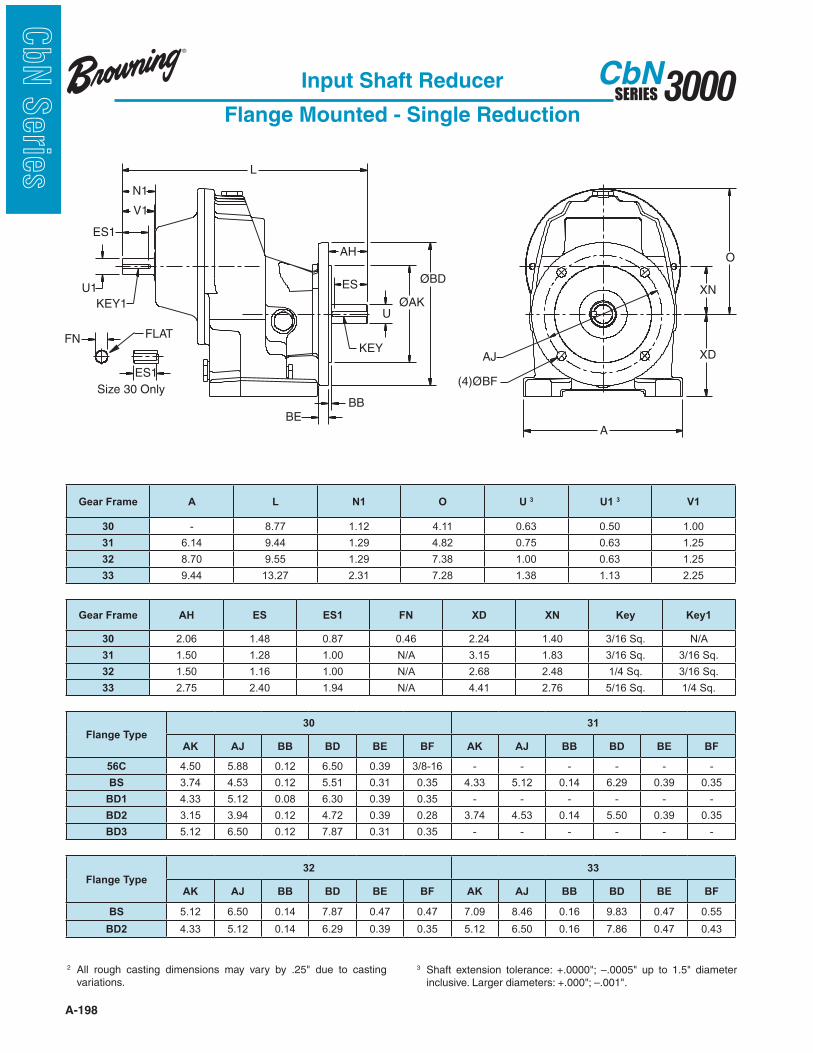
A-198
3000SERIESCbN
CbN
Serie
s
Input Shaft Reducer
Flange Mounted - Single Reduction
2 variations.
3
L
ES
AHO
U
KEYXD
XNØBD
ØAK
BEBB
AJ
(4)ØBF
U1
ES1
KEY1
N1
V1
A
Size 30 Only
ES1
FN FLAT
Gear Frame A L N1 O U 3 U1 3 V1
30 - 8.77 1.12 4.11 0.63 0.50 1.00
31 6.14 9.44 1.29 4.82 0.75 0.63 1.25
32 8.70 9.55 1.29 7.38 1.00 0.63 1.25
33 9.44 13.27 2.31 7.28 1.38 1.13 2.25
Gear Frame AH ES ES1 FN XD XN Key Key1
30 2.06 1.48 0.87 0.46 2.24 1.40 3/16 Sq. N/A
31 1.50 1.28 1.00 N/A 3.15 1.83 3/16 Sq. 3/16 Sq.
32 1.50 1.16 1.00 N/A 2.68 2.48 1/4 Sq. 3/16 Sq.
33 2.75 2.40 1.94 N/A 4.41 2.76 5/16 Sq. 1/4 Sq.
Flange Type30 31
AK AJ BB BD BE BF AK AJ BB BD BE BF
56C 4.50 5.88 0.12 6.50 0.39 3/8-16 - - - - - -
BS 3.74 4.53 0.12 5.51 0.31 0.35 4.33 5.12 0.14 6.29 0.39 0.35
BD1 4.33 5.12 0.08 6.30 0.39 0.35 - - - - - -
BD2 3.15 3.94 0.12 4.72 0.39 0.28 3.74 4.53 0.14 5.50 0.39 0.35
BD3 5.12 6.50 0.12 7.87 0.31 0.35 - - - - - -
Flange Type32 33
AK AJ BB BD BE BF AK AJ BB BD BE BF
BS 5.12 6.50 0.14 7.87 0.47 0.47 7.09 8.46 0.16 9.83 0.47 0.55
BD2 4.33 5.12 0.14 6.29 0.39 0.35 5.12 6.50 0.16 7.86 0.47 0.43

A-199
3000SERIESCbN
CbN
Serie
sInput Shaft Reducer
Flange Mounted - Single Reduction
2 variations.
3
L
ES
AHO
U
KEYXD
XNØBD
ØAK
BEBB
AJ
(4)ØBF
U1
ES1
KEY1
N1
V1
A
Gear Frame A L N1 O U 3 U1 3 V1
34 11.02 15.12 2.37 8.70 1.50 1.125 2.25
35 13.65 17.90 2.92 11.07 1.75 1.375 2.75
Gear Frame AH ES ES1 XD XN Key Key1
34 3.00 2.56 1.94 5.20 3.43 3/8 Sq. 1/4 Sq.
35 3.50 3.06 2.31 6.30 4.33 3/8 Sq. 5/16 Sq.
Flange Type34 35
AK AJ BB BD BE BF AK AJ BB BD BE BF
BS 9.06 10.43 0.16 11.80 0.59 0.55 9.84 11.81 0.20 13.78 0.71 0.71
BD2 7.09 8.46 0.16 9.83 0.59 0.55 9.06 10.43 0.20 11.81 0.71 0.55

A-200
3000SERIESCbN
CbN
Serie
s
UES
AH
L
KEY
ØBD
ØAK
BB
BE
(4)ØBF
ØAJ
XN
U1
ES1
KEY1
N1
V1
A
XD
FN
Size 30 OnlyES1
O
FLAT
Input Shaft Reducer
Flange Mounted - Double/Triple Reduction
2 variations.
3
BD3 TYPE (31)
Gear Frame A L N1 O U 3 U1 3 V1
3012 5.51 9.87 1.12 3.04 0.625 0.500 1.00
3013 5.51 10.66 1.12 3.04 0.625 0.500 1.00
31 6.77 11.50 1.29 3.06 1.000 0.625 1.20
Gear Frame AH ES ES1 FN XD XN Key Key1
3012 2.07 1.48 0.87 0.46 2.48 0.28 3/16 Sq. N/A
3013 2.07 1.48 0.87 0.46 2.48 0.28 3/16 Sq. N/A
31 1.50 1.16 1.00 N/A 3.54 0.33 1/4 Sq. 3/16 Sq.
Flange Type30 31
AK AJ BB BD BE BF AK AJ BB BD BE BF
56C 4.50 5.88 0.12 6.50 0.39 3/8-16 - - - - - -
BS 3.74 4.53 0.12 5.51 0.31 0.35 5.12 6.50 0.14 7.87 0.47 0.47
BD1 3.15 3.94 0.10 4.72 0.28 0.28 4.33 5.12 0.14 6.29 0.39 0.35
BD2 4.33 5.12 0.12 6.30 0.31 0.35 3.74 4.53 0.14 5.50 0.39 0.35
BD3 5.12 6.50 0.12 7.87 0.31 0.35 3.15 3.94 0.10 4.72 0.39 0.28

A-201
3000SERIESCbN
CbN
Serie
sInput Shaft Reducer
Flange Mounted - Double/Triple Reduction
UES
AH
L
KEY
ØBD
ØAK
BB
BE
(4)ØBF
ØAJ
XN
U1
ES1
KEY1
N1
V1
A
XD
O
Gear Frame A L N1 O U 3 U1 3 V1
32 8.70 13.25 1.29 3.50 1.250 0.625 1.25
3362,3363 10.16 17.62 2.31 4.43 1.500 1.125 2.25
3372,3373 10.16 17.77 2.31 4.43 1.625 1.125 2.25
Gear Frame AH ES ES1 FN XD XN Key Key1
32 2.50 2.16 1.00 N/A 4.53 0.39 1/4 Sq. 3/16 Sq.
3362,3363 3.00 2.56 1.94 N/A 5.51 0.77 3/8 Sq. 1/4 Sq.
3372,3373 3.15 2.78 1.94 N/A 5.51 0.77 3/8 Sq. 1/4 Sq.
Flange Type32 33
AK AJ BB BD BE BF AK AJ BB BD BE BF
BS 7.09 8.46 0.16 9.83 0.47 0.55 9.06 10.43 0.16 11.80 0.47 0.55
BD1 5.12 6.50 0.14 7.87 0.39 0.47 7.09 8.46 0.16 9.83 0.47 0.55
BD2 4.33 5.12 0.14 6.29 0.39 0.35 5.12 6.50 0.14 7.86 0.47 0.47
2 variations.
3

A-202
3000SERIESCbN
CbN
Serie
s
UES
AH
L
KEY
ØBD
ØAK
BB
BE
(4)ØBF
ØAJ
XN
U1
ES1
KEY1
N1
V1
A
XD
O
Input Shaft Reducer
Flange Mounted - Double/Triple Reduction
2 variations.
3
Gear Frame A L N1 O U 3 U1 3 V1
34 11.97 19.16 2.37 4.80 2.125 1.125 2.25
35 14.19 23.42 2.92 5.98 2.375 1.375 2.75
Gear Frame AH ES ES1 XD XN Key Key1
34 3.5 3.06 1.94 7.09 1.02 1/2 Sq. 1/4 Sq.
35 4.72 4.19 2.31 8.86 1.14 5/8 Sq. 5/16 Sq.
Flange Type34 35
AK AJ BB BD BE BF AK AJ BB BD BE BF
BS 9.84 11.81 0.16 13.77 0.59 0.71 11.81 13.78 0.20 15.75 0.71 0.71
BD1 9.06 10.43 0.16 11.80 0.59 0.55 9.84 11.81 0.20 13.78 0.71 0.71
BD2 7.09 8.46 0.16 9.83 0.59 0.55 9.06 10.43 0.20 11.81 0.71 0.55
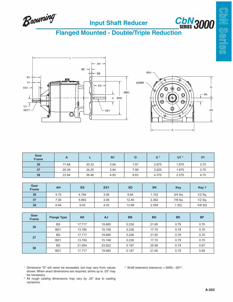
A-203
3000SERIESCbN
CbN
Serie
sInput Shaft Reducer
Flanged Mounted - Double/Triple Reduction
XN
ES
U
BE
AH
BB
KEY
O
XD
ØAJ
(8)ØBF
A
ØAK
ØBD
L
ES1
V1
N1
U1
KEY1
Gear
FrameA L N1 O U 3 U1 3 V1
36 17.68 30.32 3.94 7.87 2.875 1.875 3.75
37 20.39 34.25 3.94 7.99 3.625 1.875 3.75
38 23.94 38.46 4.93 8.63 4.375 2.375 4.75
Gear
FrameAH ES ES1 XD XN Key Key 1
36 5.75 4.784 3.06 9.84 1.102 3/4 Sq 1/2 Sq.
37 7.00 5.893 3.06 12.40 2.362 7/8 Sq 1/2 Sq.
38 6.84 9.02 4.03 13.98 2.559 1 SQ 5/8 SQ
Gear
FrameFlange Type AK AJ BB BD BE BF
36BS 17.717 19.685 0.236 21.65 0.79 0.70
BD1 13.780 15.748 0.236 17.70 0.79 0.70
37BS 17.717 19.685 0.236 21.65 0.79 0.70
BD1 13.780 15.748 0.236 17.70 0.79 0.70
38BS 21.654 23.622 0.197 25.98 0.79 0.87
BD1 17.717 19.685 0.197 21.65 0.79 0.69
1 Dimension “D” will never be exceeded, but may vary from values
be necessary.2
variations.
3
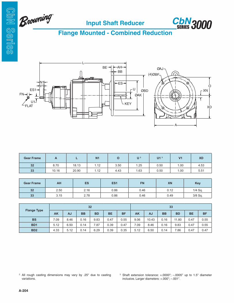
A-204
3000SERIESCbN
CbN
Serie
s
L
V1N1
ES1
U1
FN
AH
BB
BE
ES
U
KEY
ØAK
ØBD
A
ØAJ
(4)ØBF
XN
XD
O
FLAT
Input Shaft Reducer
Flange Mounted - Combined Reduction
2 variations.
3
Gear Frame A L N1 O U 3 U1 3 V1 XD
32 8.70 18.13 1.12 3.50 1.25 0.50 1.00 4.53
33 10.16 20.90 1.12 4.43 1.63 0.50 1.00 5.51
Gear Frame AH ES ES1 FN XN Key
32 2.50 2.16 0.86 0.46 0.12 1/4 Sq.
33 3.15 2.78 0.86 0.46 0.49 3/8 Sq.
Flange Type32 33
AK AJ BB BD BE BF AK AJ BB BD BE BF
BS 7.09 8.46 0.16 9.83 0.47 0.55 9.06 10.43 0.16 11.80 0.47 0.55
BD1 5.12 6.50 0.14 7.87 0.39 0.47 7.09 8.46 0.16 9.83 0.47 0.55
BD2 4.33 5.12 0.14 6.29 0.39 0.35 5.12 6.50 0.14 7.86 0.47 0.47

A-205
3000SERIESCbN
CbN
Serie
s
L
V1N1
ES1
U1
AH
BB
BE
ES
U
KEY
ØAK
ØBD
A
ØAJ
(4)ØBF
XN
XD
O
Input Shaft Reducer
Flange Mounted - Combined Reduction
2 variations.
3
Gear Frame A L N1 O U 3 U1 3 V1
34 11.97 24.29 1.29 4.80 2.125 1.125 1.25
35 14.19 26.86 1.29 5.98 2.125 0.625 1.25
Gear Frame AH ES ES1 XD XN Key Key1
34 3.50 3.06 1.00 7.09 1.35 1/2 Sq. 3/16 Sq.
35 4.72 4.19 1.00 8.86 1.47 5/8 Sq. 3/16 Sq.
Flange Type34 35
AK AJ BB BD BE BF AK AJ BB BD BE BF
BS 9.84 11.81 0.16 13.77 0.59 0.71 11.81 13.78 0.20 15.75 0.71 0.71
BD1 9.06 10.43 0.16 11.80 0.59 0.55 9.84 11.81 0.20 13.78 0.71 0.71
BD2 7.09 8.46 0.16 9.83 0.59 0.55 9.06 10.43 0.20 11.81 0.71 0.55

A-206
3000SERIESCbN
CbN
Serie
s
Input Shaft Reducer
Flange Mounted - Combined Reduction
1 Dimension “D” will never be exceeded, but may vary from values
be necessary.
2 variations.
3
ES
U
KEY
ØAK
ØBD
BE
AH
BB
XN
O
XD
ØAJ
(8)ØBF
A
U1
ES1
V1
N1
L
KEY1
Gear
FrameA L N1 O U 3 U1 3 V1
36 17.68 32.98 1.35 7.87 2.875 0.63 1.25
37 20.39 36.91 1.35 7.99 3.625 0.63 1.25
38 23.94 43.92 2.37 8.63 4.375 1.125 2.25
Gear
FrameAH ES ES1 XD XN Key Key 1
36 5.75 4.784 1.00 9.86 1.492 3/4 Sq 3/16 Sq.
37 7.00 5.893 1.00 12.40 2.752 7/8 Sq 3/16 Sq.
38 6.84 9.02 1.94 13.98 2.559 1 SQ 1/4 SQ
Gear
Frame
Flange
TypeAK AJ BB BD BE BF
36BS 17.717 19.685 0.236 21.65 0.79 0.70
BD1 13.780 15.748 0.236 17.70 0.79 0.70
37BS 17.717 19.685 0.236 21.65 0.79 0.70
BD1 13.780 15.748 0.236 17.70 0.79 0.70
38BS 21.654 23.620 0.197 25.98 0.79 0.87
BD1 17.717 19.685 0.197 21.65 0.79 0.69

A-207
3000SERIESCbN
CbN
Serie
sTop Mount Reducer
Foot Mounted - Single Reduction
1 Dimension “D” will never be exceeded, but may vary from values
be necessary.
2 variations.
3
D
XN
CM
E E
A
9.00
LT
LS
ES1
U1
HS
HTCENTER
DISTANCE
KEY1
(4)ØH
G
U
KEY
ES
BA
V
2F
B
MV1
Gear Frame A B D 1 E G H M U 3 U1 3 V V1 BA
34 12.47 6.59 5.20 4.25 1.34 0.71 9.10 1.50 1.13 3.00 2.25 1.10
35 15.45 7.76 6.30 5.12 1.61 0.79 10.38 1.75 1.38 3.50 2.75 1.18
Gear Frame CM 2F HSHT
LS LT ES ES1 XN Key Key1Min. Max.
34 16.50 4.92 14.48 1.89 7.36 2.35 15.50 2.56 1.94 3.43 3/8 Sq. 1/4 Sq.
35 20.00 6.30 10.48 1.89 7.36 2.72 20.25 3.06 2.31 4.33 3/8 Sq. 5/16 Sq.
Motor Frame34 Center Distance 35 Center Distance
Min. Max. Min. Max.
143/145T 13.87 19.34 15.87 21.34
182/184T 14.87 20.34 16.87 22.34
213/215T 15.62 21.09 17.62 23.09
254/256T - - 18.62 24.09
284/286T - - 19.37 24.84
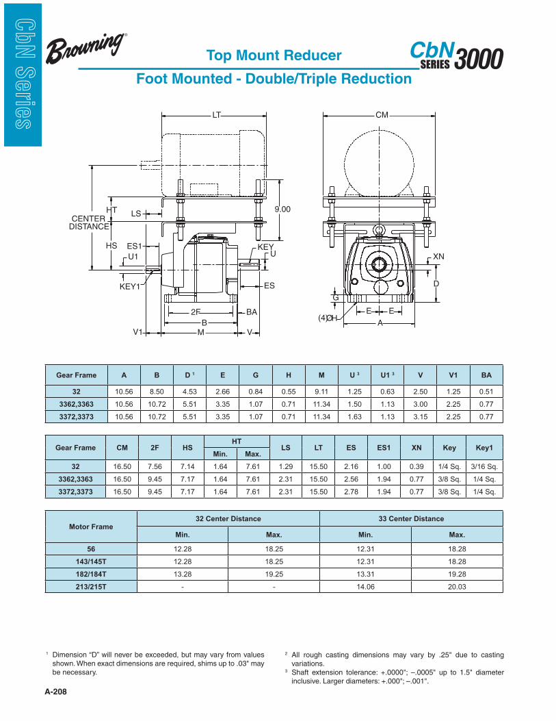
A-208
3000SERIESCbN
CbN
Serie
s
D
XN
CM
E
A
E(4)ØH
G
LT
B
2F BA
ES
V
UKEY
MV1
ES1
U1
HS
KEY1
LS9.00HT
CENTER
DISTANCE
Top Mount Reducer
Foot Mounted - Double/Triple Reduction
1 Dimension “D” will never be exceeded, but may vary from values
be necessary.
2 variations.
3
Gear Frame A B D 1 E G H M U 3 U1 3 V V1 BA
32 10.56 8.50 4.53 2.66 0.84 0.55 9.11 1.25 0.63 2.50 1.25 0.51
3362,3363 10.56 10.72 5.51 3.35 1.07 0.71 11.34 1.50 1.13 3.00 2.25 0.77
3372,3373 10.56 10.72 5.51 3.35 1.07 0.71 11.34 1.63 1.13 3.15 2.25 0.77
Gear Frame CM 2F HSHT
LS LT ES ES1 XN Key Key1Min. Max.
32 16.50 7.56 7.14 1.64 7.61 1.29 15.50 2.16 1.00 0.39 1/4 Sq. 3/16 Sq.
3362,3363 16.50 9.45 7.17 1.64 7.61 2.31 15.50 2.56 1.94 0.77 3/8 Sq. 1/4 Sq.
3372,3373 16.50 9.45 7.17 1.64 7.61 2.31 15.50 2.78 1.94 0.77 3/8 Sq. 1/4 Sq.
Motor Frame32 Center Distance 33 Center Distance
Min. Max. Min. Max.
56 12.28 18.25 12.31 18.28
143/145T 12.28 18.25 12.31 18.28
182/184T 13.28 19.25 13.31 19.28
213/215T - - 14.06 20.03

A-209
3000SERIESCbN
CbN
Serie
s
D
XN
CM
E
A
E(4)ØH
G
LT
B
2F BA
ES
V
UKEY
MV1
ES1
U1
HS
KEY1
LS9.00HT
CENTER
DISTANCE
Top Mount Reducer
Foot Mounted - Double/Triple Reduction
1 Dimension “D” will never be exceeded, but may vary from values
be necessary.
2 variations.
3
Gear Frame A B D 1 E G H M U 3 U1 3 V V1 BA
34 12.47 10.87 7.09 4.53 1.37 0.71 12.66 2.13 1.13 3.50 2.25 0.98
35 15.45 12.89 8.86 5.51 1.73 0.87 14.95 2.38 1.38 4.72 2.75 1.10
Gear Frame CM 2F HSHT
LS LT ES ES1 XN Key Key1Min. Max.
34 16.50 9.25 14.48 1.89 7.36 2.35 15.50 3.06 1.94 1.02 1/2 Sq. 1/4 Sq.
35 20.00 11.02 10.48 1.89 7.36 2.72 20.25 4.19 2.31 1.14 5/8 Sq. 5/16 Sq.
Motor Frame34 Center Distance 35 Center Distance
Min. Max. Min. Max.
143/145T 13.87 19.34 15.87 21.34
182/184T 14.87 20.34 16.87 22.34
213/215T 15.62 21.09 17.62 23.09
254/256T 16.62 22.09 18.62 24.09
284/286T - - 19.37 24.84
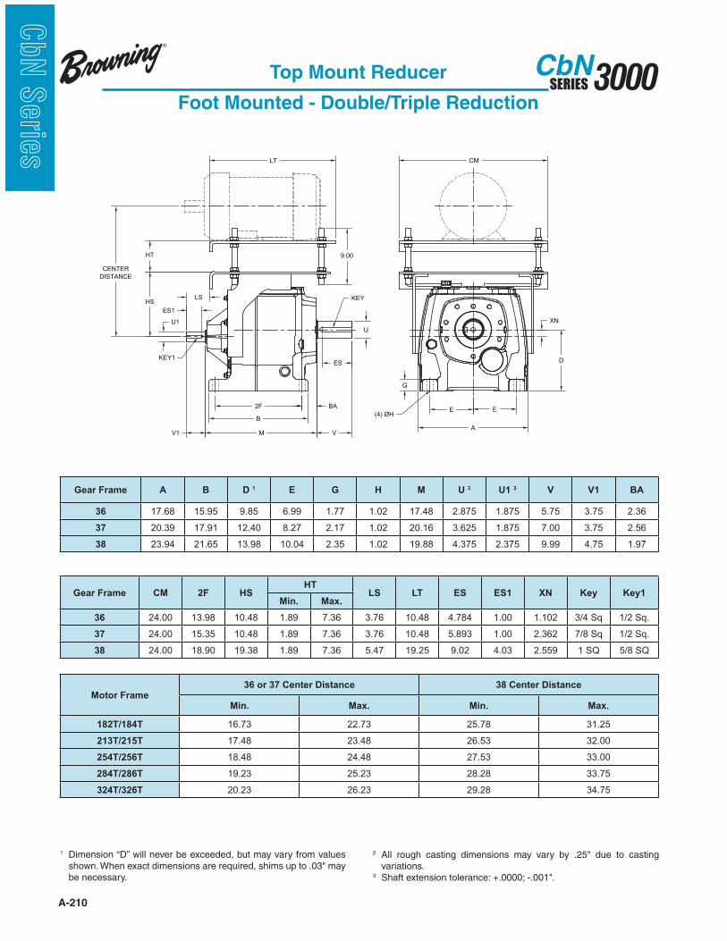
A-210
3000SERIESCbN
CbN
Serie
s
U1
CENTER
DISTANCE
HS
HT
LT
LS
9.00
CM
B
XN
2F BA
V
ES
U
KEY
D
E E
A
G
(4) ØH
ES1
KEY1
MV1
Top Mount Reducer
Foot Mounted - Double/Triple Reduction
1 Dimension “D” will never be exceeded, but may vary from values
be necessary.
2 variations.
3
Gear Frame A B D 1 E G H M U 3 U1 3 V V1 BA
36 17.68 15.95 9.85 6.99 1.77 1.02 17.48 2.875 1.875 5.75 3.75 2.36
37 20.39 17.91 12.40 8.27 2.17 1.02 20.16 3.625 1.875 7.00 3.75 2.56
38 23.94 21.65 13.98 10.04 2.35 1.02 19.88 4.375 2.375 9.99 4.75 1.97
Gear Frame CM 2F HSHT
LS LT ES ES1 XN Key Key1Min. Max.
36 24.00 13.98 10.48 1.89 7.36 3.76 10.48 4.784 1.00 1.102 3/4 Sq 1/2 Sq.
37 24.00 15.35 10.48 1.89 7.36 3.76 10.48 5.893 1.00 2.362 7/8 Sq 1/2 Sq.
38 24.00 18.90 19.38 1.89 7.36 5.47 19.25 9.02 4.03 2.559 1 SQ 5/8 SQ
Motor Frame36 or 37 Center Distance 38 Center Distance
Min. Max. Min. Max.
182T/184T 16.73 22.73 25.78 31.25
213T/215T 17.48 23.48 26.53 32.00
254T/256T 18.48 24.48 27.53 33.00
284T/286T 19.23 25.23 28.28 33.75
324T/326T 20.23 26.23 29.28 34.75
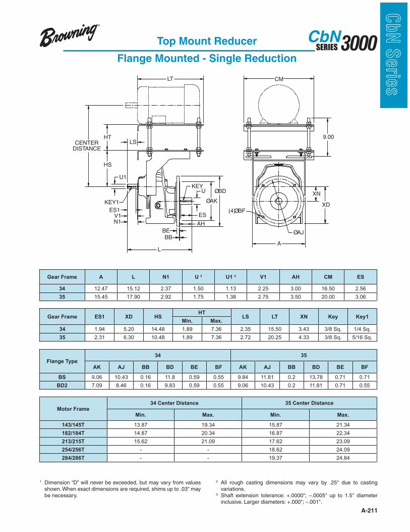
A-211
3000SERIESCbN
CbN
Serie
s
(4)ØBF
N1
ES1
L
ØAK
ØBD
BEBB
AH
ESV1
KEYU
KEY1
CENTER
DISTANCE
HT
HS
U1
LS
LT
9.00
A
CM
XN
XD
ØAJ
Top Mount Reducer
Flange Mounted - Single Reduction
1 Dimension “D” will never be exceeded, but may vary from values
be necessary.
2 variations.
3
Gear Frame A L N1 U 3 U1 3 V1 AH CM ES
34 12.47 15.12 2.37 1.50 1.13 2.25 3.00 16.50 2.56
35 15.45 17.90 2.92 1.75 1.38 2.75 3.50 20.00 3.06
Gear Frame ES1 XD HSHT
LS LT XN Key Key1Min. Max.
34 1.94 5.20 14.48 1.89 7.36 2.35 15.50 3.43 3/8 Sq. 1/4 Sq.
35 2.31 6.30 10.48 1.89 7.36 2.72 20.25 4.33 3/8 Sq. 5/16 Sq.
Flange Type34 35
AK AJ BB BD BE BF AK AJ BB BD BE BF
BS 9.06 10.43 0.16 11.8 0.59 0.55 9.84 11.81 0.2 13.78 0.71 0.71
BD2 7.09 8.46 0.16 9.83 0.59 0.55 9.06 10.43 0.2 11.81 0.71 0.55
Motor Frame34 Center Distance 35 Center Distance
Min. Max. Min. Max.
143/145T 13.87 19.34 15.87 21.34
182/184T 14.87 20.34 16.87 22.34
213/215T 15.62 21.09 17.62 23.09
254/256T - - 18.62 24.09
284/286T - - 19.37 24.84
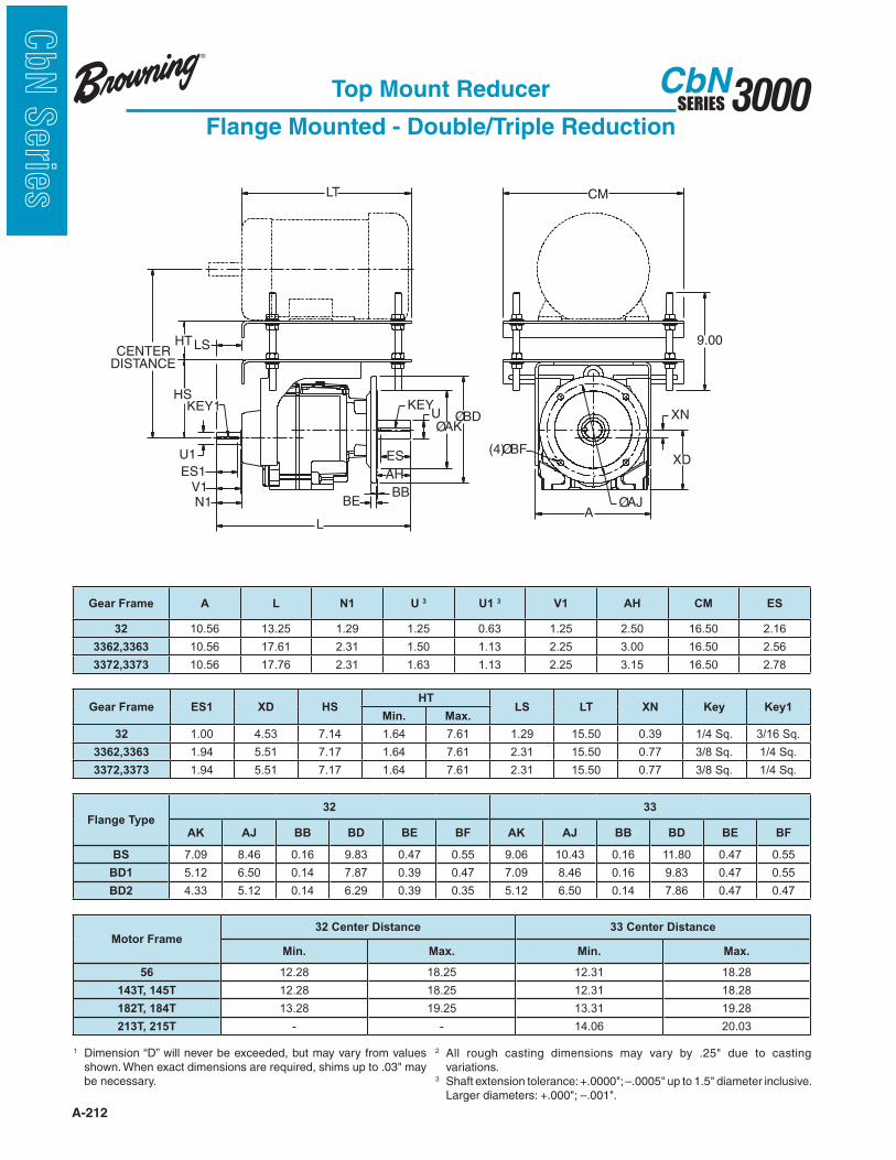
A-212
3000SERIESCbN
CbN
Serie
s
Top Mount Reducer
Flange Mounted - Double/Triple Reduction
1 Dimension “D” will never be exceeded, but may vary from values
be necessary.
ØAJ
(4)ØBF
KEYKEY1ØBD
ØAK
HS
L
ES1
U1
N1V1
BE
AH
BB
ES
U
LT
LSHT 9.00
XN
A
XD
CM
CENTER
DISTANCE
2 variations.
3
Gear Frame A L N1 U 3 U1 3 V1 AH CM ES
32 10.56 13.25 1.29 1.25 0.63 1.25 2.50 16.50 2.16
3362,3363 10.56 17.61 2.31 1.50 1.13 2.25 3.00 16.50 2.56
3372,3373 10.56 17.76 2.31 1.63 1.13 2.25 3.15 16.50 2.78
Gear Frame ES1 XD HSHT
LS LT XN Key Key1Min. Max.
32 1.00 4.53 7.14 1.64 7.61 1.29 15.50 0.39 1/4 Sq. 3/16 Sq.
3362,3363 1.94 5.51 7.17 1.64 7.61 2.31 15.50 0.77 3/8 Sq. 1/4 Sq.
3372,3373 1.94 5.51 7.17 1.64 7.61 2.31 15.50 0.77 3/8 Sq. 1/4 Sq.
Flange Type32 33
AK AJ BB BD BE BF AK AJ BB BD BE BF
BS 7.09 8.46 0.16 9.83 0.47 0.55 9.06 10.43 0.16 11.80 0.47 0.55
BD1 5.12 6.50 0.14 7.87 0.39 0.47 7.09 8.46 0.16 9.83 0.47 0.55
BD2 4.33 5.12 0.14 6.29 0.39 0.35 5.12 6.50 0.14 7.86 0.47 0.47
Motor Frame32 Center Distance 33 Center Distance
Min. Max. Min. Max.
56 12.28 18.25 12.31 18.28
143T, 145T 12.28 18.25 12.31 18.28
182T, 184T 13.28 19.25 13.31 19.28
213T, 215T - - 14.06 20.03

A-213
3000SERIESCbN
CbN
Serie
sTop Mount Reducer
Flange Mounted - Double/Triple Reduction
1 Dimension “D” will never be exceeded, but may vary from values
be necessary.
2 variations.
3
ØAJ
(4)ØBF
KEYKEY1ØBD
ØAK
HS
L
ES1
U1
N1V1
BE
AH
BB
ES
U
LT
LSHT 9.00
XN
A
XD
CM
CENTER
DISTANCE
Gear Frame A L N1 U 3 U1 3 V1 AH CM ES
34 12.47 19.16 2.37 2.13 1.13 2.25 3.50 16.50 3.06
35 15.45 23.42 2.92 2.13 1.38 2.75 4.72 20.00 4.19
Gear Frame ES1 XD HSHT
LS LT XN Key Key1Min. Max.
34 1.94 7.09 14.48 1.89 7.36 2.35 15.5 1.02 1/2 Sq. 1/4 Sq.
35 2.31 8.86 10.48 1.89 7.36 2.72 20.25 1.14 5/8 Sq. 5/16 Sq.
Flange Type34 35
AK AJ BB BD BE BF AK AJ BB BD BE BF
BS 9.84 11.81 0.16 13.77 0.59 0.71 11.81 13.78 0.20 15.75 0.71 0.71
BD1 9.06 10.43 0.16 11.80 0.59 0.55 9.84 11.81 0.20 13.78 0.71 0.71
BD2 7.09 8.46 0.16 9.83 0.59 0.55 9.06 10.43 0.20 11.81 0.71 0.55
Motor Frame34 Center Distance 35 Center Distance
Min. Max. Min. Max.
143/145T 13.87 19.34 15.87 21.34
182/184T 14.87 20.34 16.87 22.34
213/215T 15.62 21.09 17.62 23.09
254/256T 16.62 22.09 18.62 24.09
284/286T - - 19.37 24.84
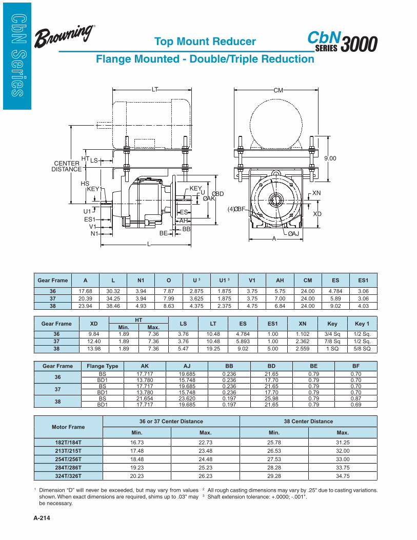
A-214
3000SERIESCbN
CbN
Serie
s
Top Mount Reducer
Flange Mounted - Double/Triple Reduction
1 Dimension “D” will never be exceeded, but may vary from values
be necessary.
ØAJ
(4)ØBF
KEYKEY1ØBD
ØAK
HS
L
ES1
U1
N1V1
BE
AH
BB
ES
U
LT
LSHT 9.00
XN
A
XD
CM
CENTER
DISTANCE
2 3
Gear Frame A L N1 O U 3 U1 3 V1 AH CM ES ES1
36 17.68 30.32 3.94 7.87 2.875 1.875 3.75 5.75 24.00 4.784 3.06
37 20.39 34.25 3.94 7.99 3.625 1.875 3.75 7.00 24.00 5.89 3.06
38 23.94 38.46 4.93 8.63 4.375 2.375 4.75 6.84 24.00 9.02 4.03
Gear Frame XDHT
LS LT ES ES1 XN Key Key 1Min. Max.
36 9.84 1.89 7.36 3.76 10.48 4.784 1.00 1.102 3/4 Sq 1/2 Sq.
37 12.40 1.89 7.36 3.76 10.48 5.893 1.00 2.362 7/8 Sq 1/2 Sq.
38 13.98 1.89 7.36 5.47 19.25 9.02 5.00 2.559 1 SQ 5/8 SQ
Gear Frame Flange Type AK AJ BB BD BE BF
36BS 17.717 19.685 0.236 21.65 0.79 0.70
BD1 13.780 15.748 0.236 17.70 0.79 0.70
37BS 17.717 19.685 0.236 21.65 0.79 0.70
BD1 13.780 15.748 0.236 17.70 0.79 0.70
38BS 21.654 23.620 0.197 25.98 0.79 0.87
BD1 17.717 19.685 0.197 21.65 0.79 0.69
Motor Frame36 or 37 Center Distance 38 Center Distance
Min. Max. Min. Max.
182T/184T 16.73 22.73 25.78 31.25
213T/215T 17.48 23.48 26.53 32.00
254T/256T 18.48 24.48 27.53 33.00
284T/286T 19.23 25.23 28.28 33.75
324T/326T 20.23 26.23 29.28 34.75
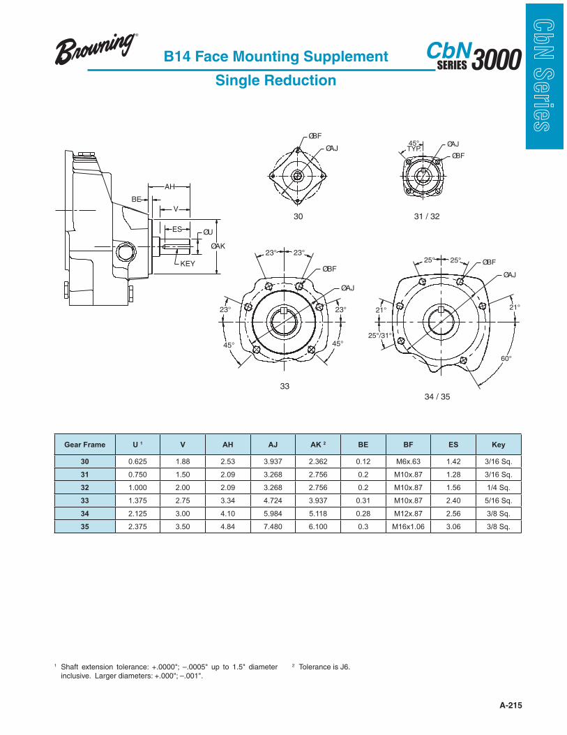
A-215
3000SERIESCbN
CbN
Serie
sB14 Face Mounting Supplement
Single Reduction
1
ØU
KEY
V
ES
BE
AH
ØAK
ØAJ
ØBF
30
ØBF
ØAJ45°TYP.
31 / 32
23°23°
23° 23°
45° 45°
ØBF
ØAJ
33
21°
25°25°
21°
25°/31°
60°
ØBF
ØAJ
34 / 35
Gear Frame U 1 V AH AJ AK 2 BE BF ES Key
30 0.625 1.88 2.53 3.937 2.362 0.12 M6x.63 1.42 3/16 Sq.
31 0.750 1.50 2.09 3.268 2.756 0.2 M10x.87 1.28 3/16 Sq.
32 1.000 2.00 2.09 3.268 2.756 0.2 M10x.87 1.56 1/4 Sq.
33 1.375 2.75 3.34 4.724 3.937 0.31 M10x.87 2.40 5/16 Sq.
34 2.125 3.00 4.10 5.984 5.118 0.28 M12x.87 2.56 3/8 Sq.
35 2.375 3.50 4.84 7.480 6.100 0.3 M16x1.06 3.06 3/8 Sq.
2 Tolerance is J6.
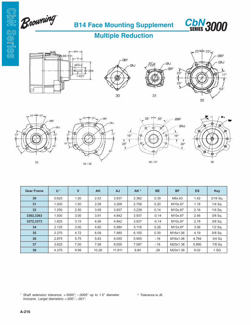
A-216
3000SERIESCbN
CbN
Serie
s
B14 Face Mounting Supplement
Multiple Reduction
1
2 Tolerance is J6.
AH
ØAKØU
KEY
V
ES
BE
ØAJ
ØBF
30
ØBF
ØAJ45°TYP.
31
23°
17°23°
25°
63°
ØAJ
ØBF
23°
32
Gear Frame U 1 V AH AJ AK 2 BE BF ES Key
30 0.625 1.50 2.53 3.937 2.362 0.39 M6x.63 1.42 3/16 Sq.
31 1.000 1.50 2.09 3.268 2.756 0.20 M10x.87 1.16 1/4 Sq.
32 1.250 2.50 3.09 3.937 3.228 0.14 M10x.87 2.16 1/4 Sq.
3362,3363 1.500 3.00 3.91 4.842 3.937 -0.14 M10x.87 2.56 3/8 Sq.
3372,3373 1.625 3.15 4.06 4.842 3.937 -0.14 M10x.87 2.78 3/8 Sq.
34 2.125 3.50 4.60 5.984 5.118 0.28 M12x.87 3.06 1/2 Sq.
35 2.375 4.72 6.09 7.480 6.100 0.30 M16x1.06 4.19 5/8 Sq.
36 2.875 5.75 5.83 9.055 5.905 -.16 M16x1.06 4.784 3/4 Sq
37 3.625 7.00 7.08 9.055 7.087 -.16 M20x1.38 5.890 7/8 Sq
38 4.375 9.99 10.26 11.811 9.84 .28 M20x1.38 9.02 1 SQ
23°23°
23° 23°
45° 45°
ØBF
ØAJ
33
21°
25°25°
21°
25°/31°
60°
ØBF
ØAJ
34 / 35
15°
20°
35° 35°
15°
20°
ØAJ
ØBF
36 / 37 38

A-217
3000SERIESCbN
CbN
Serie
sMetric Output Shaft Dimensions
SM Foot Mounted - Single Reduction
EY
V
U
EX
GA
F
Gear Frame F U GA V EX EY
30 5 16j6 18 40 7 25
31 6 20j6 22,5 40 7 30
32 8 25j6 28 50 5 40
33 10 35k6 38 70 5 60
34 12 40k6 43 80 3 72
35 14 45 48.5 90 5 80
Dimensionsin mm
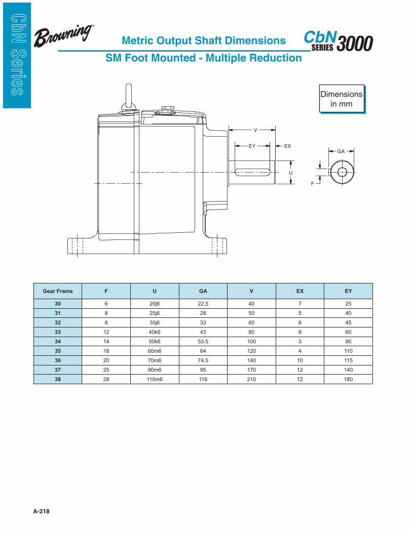
A-218
3000SERIESCbN
CbN
Serie
s
V
EY EX
GA
F
U
Metric Output Shaft Dimensions
SM Foot Mounted - Multiple Reduction
Gear Frame F U GA V EX EY
30 6 20j6 22,5 40 7 25
31 8 25j6 28 50 5 40
32 8 30j6 33 60 6 45
33 12 40k6 43 80 9 60
34 14 50k6 53.5 100 3 90
35 18 60m6 64 120 4 110
36 20 70m6 74.5 140 10 115
37 25 90m6 95 170 12 140
38 28 110m6 116 210 12 180
Dimensionsin mm
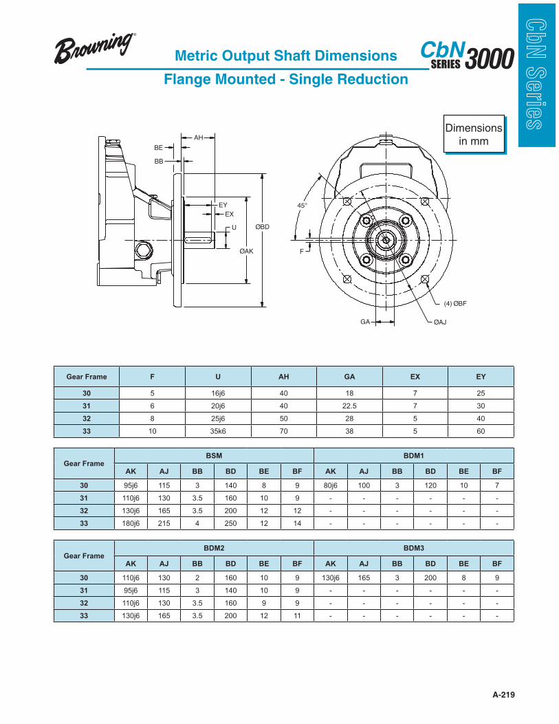
A-219
3000SERIESCbN
CbN
Serie
s
EY
AH
BB
BE
ØAK
ØBDU
(4) ØBF
ØAJ
F
GA
EX
45°
Metric Output Shaft Dimensions
Flange Mounted - Single Reduction
Gear Frame F U AH GA EX EY
30 5 16j6 40 18 7 25
31 6 20j6 40 22.5 7 30
32 8 25j6 50 28 5 40
33 10 35k6 70 38 5 60
Gear FrameBSM BDM1
AK AJ BB BD BE BF AK AJ BB BD BE BF
30 95j6 115 3 140 8 9 80j6 100 3 120 10 7
31 110j6 130 3.5 160 10 9 - - - - - -
32 130j6 165 3.5 200 12 12 - - - - - -
33 180j6 215 4 250 12 14 - - - - - -
Gear FrameBDM2 BDM3
AK AJ BB BD BE BF AK AJ BB BD BE BF
30 110j6 130 2 160 10 9 130j6 165 3 200 8 9
31 95j6 115 3 140 10 9 - - - - - -
32 110j6 130 3.5 160 9 9 - - - - - -
33 130j6 165 3.5 200 12 11 - - - - - -
Dimensionsin mm
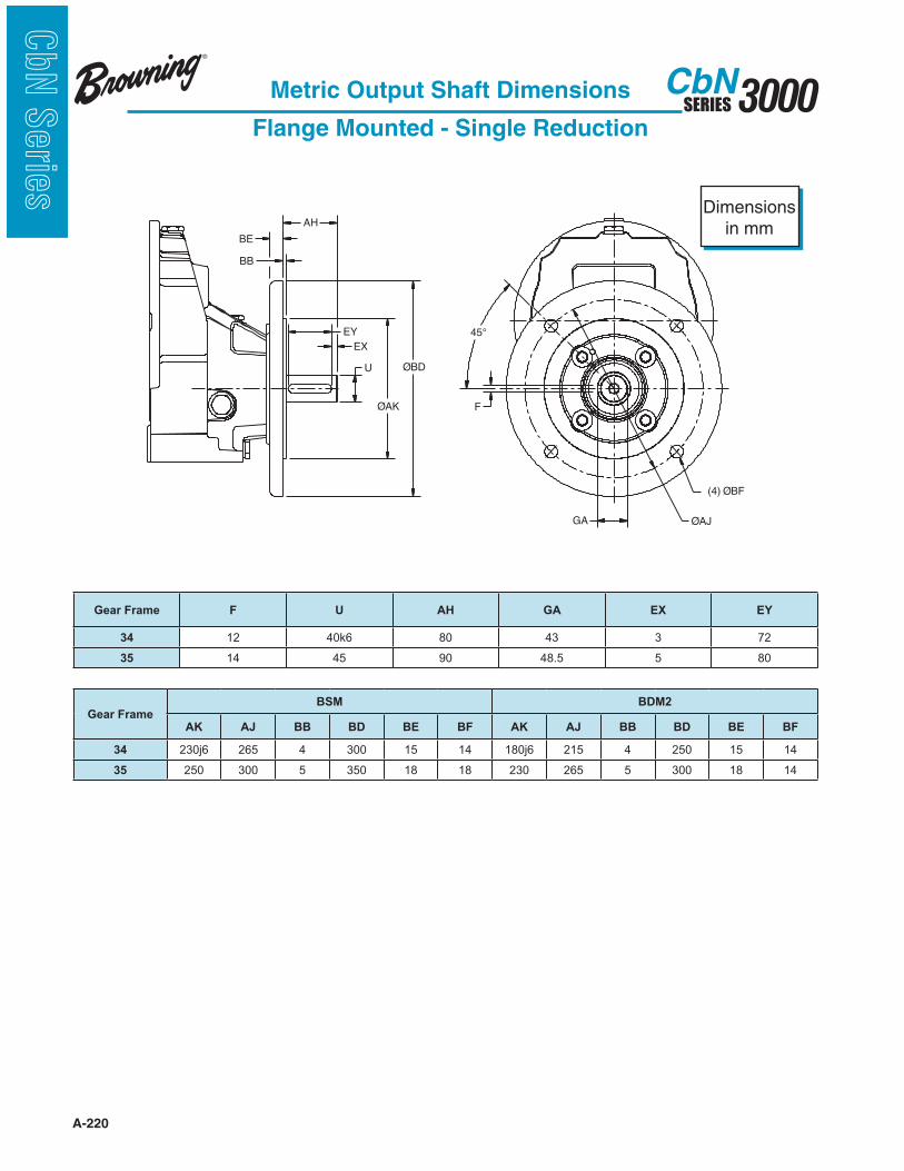
A-220
3000SERIESCbN
CbN
Serie
s
Metric Output Shaft Dimensions
Flange Mounted - Single Reduction
EY
AH
BB
BE
ØAK
ØBDU
(4) ØBF
ØAJ
F
GA
EX
45°
Gear Frame F U AH GA EX EY
34 12 40k6 80 43 3 72
35 14 45 90 48.5 5 80
Gear FrameBSM BDM2
AK AJ BB BD BE BF AK AJ BB BD BE BF
34 230j6 265 4 300 15 14 180j6 215 4 250 15 14
35 250 300 5 350 18 18 230 265 5 300 18 14
Dimensionsin mm

A-221
3000SERIESCbN
CbN
Serie
s
F
GAØAJ
(4)ØB
34 / 35
45°
AH
Metric Output Shaft Dimensions
Flange Mounted - Multiple Reduction
BD3 TYPE (31)
(1) Refer to illustration above for correct hole orientation in BDM3 flange.
Gear Frame F U AH GA EX EY
30 6 20j6 40 22.5 7 25
31 8 25j6 50 28 5 40
32 8 30j6 60 33 6 45
33 12 40k6 80 43 9 6
Gear
Frame
BSM BDM1 BDM2
AK AJ BB BD BE BF AK AJ BB BD BE BF AK AJ BB BD BE BF
30 95j6 115 3 140 8 9 80j6 100 2.5 120 7 7 110j6 130 3 160 8 9
31 130j6 165 3.5 200 10 11 110j6 130 3.5 160 10 9 95j6 115 3.5 140 10 9
32 180j6 215 4 250 12 14 130j6 165 3.5 200 10 11 110j6 130 3.5 160 10 9
33 230j6 265 4 300 12 14 180j6 215 4 250 12 14 130j6 165 3.5 200 12 11
Gear FrameBDM3
AK AJ BB BD BE BF
31 (1) 80j6 100 2,5 120 10 7
Dimensionsin mm

A-222
3000SERIESCbN
CbN
Serie
s
Metric Output Shaft Dimensions
Flange Mounted - Multiple Reduction
EX
EY
AH
BB
BE
ØAK
ØBD
U
Gear Frame F U AH GA EX EY
34 14 50k6 100 53.5 9 85
35 18 60m6 120 64 4 110
36 14 70m6 140 51.5 10 90
37 14 90m6 170 51.5 10 90
38 28 110m6 210 116 12 180
Gear
Frame
BS BD1 BD2
AK AJ BB BD BE BF AK AJ BB BD BE BF AK AJ BB BD BE BF
34 250 300 4 350 15 18 230 265 4 300 15 14 180 215 4 250 15 14
35 300 350 5 400 18 18 250 300 5 350 15 18 230 265 5 300 15 14
36 450 500 6 550 20 18 350 400 6 450 20 18
37 450 500 6 550 20 18 350 400 6 450 20 18
38 550 600 6 660 16 22 450 500 5 550 20 18
Dimensionsin mm
GAØAJ
22.5°
F
(8) ØBF45°
36, 37, 38
F
GAØAJ
(4)ØB
34 / 35
45°
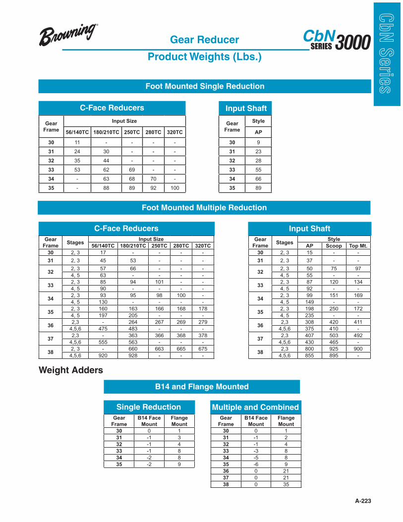
A-223
3000SERIESCbN
CbN
Serie
sGear Reducer
Product Weights (Lbs.)
Foot Mounted Single Reduction
Foot Mounted Multiple Reduction
B14 and Flange Mounted
Weight Adders
Single Reduction Multiple and Combined
C-Face Reducers Input Shaft
C-Face Reducers Input Shaft
Gear
Frame
Input Size Gear
Frame
Style
56/140TC 180/210TC 250TC 280TC 320TC AP
30 11 - - - - 30 9
31 24 30 - - - 31 23
32 35 44 - - - 32 28
33 53 62 69 - - 33 55
34 - 63 68 70 - 34 66
35 - 88 89 92 100 35 89
Gear
FrameStages
Input Size Gear
FrameStages
Style
56/140TC 180/210TC 250TC 280TC 320TC AP Scoop Top Mt.
30 2, 3 17 - - - - 30 2, 3 15 - -
31 2, 3 45 53 - - - 31 2, 3 37 - -
322, 3 57 66 - - -
322, 3 50 75 97
4, 5 63 - - - - 4, 5 55 - -
332, 3 85 94 101 - -
332, 3 87 120 134
4, 5 90 - - - - 4, 5 92 - -
342, 3 93 95 98 100 -
342, 3 99 151 169
4, 5 130 - - - - 4, 5 149 - -
352, 3 160 163 166 168 178
352, 3 198 250 172
4, 5 197 205 - - - 4, 5 235 - -
362,3 - 264 267 269 279
362,3 308 420 411
4,5,6 475 483 - - - 4,5,6 375 410 -
372,3 - 363 366 368 378
372,3 407 503 492
4,5,6 555 563 - - - 4,5,6 430 465 -
382, 3 - 660 663 665 675
382,3 800 925 900
4,5,6 920 928 - - - 4,5,6 855 895 -
Gear
Frame
B14 Face
Mount
Flange
Mount
Gear
Frame
B14 Face
Mount
Flange
Mount
30 0 1 30 0 1
31 -1 3 31 -1 2
32 -1 4 32 -1 4
33 -1 8 33 -3 8
34 -2 8 34 -5 8
35 -2 9 35 -6 9
36 0 21
37 0 21
38 0 35
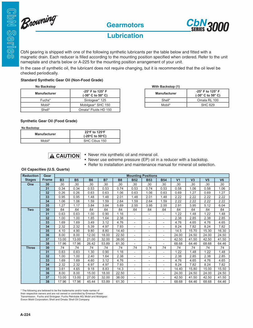
A-224
3000SERIESCbN
CbN
Serie
s
Gearmotors
Lubrication
CbN gearing is shipped with one of the following synthetic lubricants per the table below and fitted with a magnetic drain. Each reducer is filled according to the mounting position specified when ordered. Refer to the unit nameplate and charts below or A-225 for the mounting position arrangement of your unit.
In the case of synthetic oil, the lubricant does not require changing, but it is recommended that the oil level be checked periodically.
Oil Capacities (U.S. Quarts)
Standard Synthetic Gear Oil (Non-Food Grade)
* The following are believed to be the trademarks and/or trade names of their respective owners and are not owned or controlled by Emerson Power
No Backstop
Manufacturer-25° F to 125° F
(-30° C to 50° C)
Fuchs* Sintogear* 125
Mobil* Mobilgear* SHC 150
Shell* Omala* Fluids HD 150
With Backstop (1)
Manufacturer-25° F to 125° F
(-30° C to 50° C)
Shell* Omala RL 100
Mobil* SHC 629
Reduction
Stages
Gear
Frame
Mounting Positions
B3 B5 B6 B7 B8 B52 B53 B54 V1 V3 V5 V6
One 30 .30 .30 .30 .30 .30 .30 .30 .30 .30 .30 .30 .30
31 0.34 0.34 0.53 0.53 0.74 0.53 0.74 0.53 0.58 1.06 0.58 1.06
32 0.26 0.26 0.63 0.63 1.06 0.63 1.06 0.63 0.69 1.27 0.69 1.27
33 0.95 0.95 1.48 1.48 2.01 1.48 2.01 1.48 2.22 2.22 2.22 2.22
34 1.06 1.06 1.59 1.59 2.64 1.59 2.64 1.59 2.22 2.22 2.22 2.22
35 1.27 1.17 3.84 3.84 5.69 2.55 3.95 2.55 2.91 3.95 5.12 6.04
Two 30 .64 .64 .64 .64 .64 .64 .64 .64 .64 .64 .64 .64
31 0.63 0.63 1.00 0.90 1.16 - - - 1.22 1.48 1.22 1.48
32 1.00 1.00 1.85 1.64 2.38 - - - 2.38 2.85 2.38 2.85
33 1.69 1.69 3.49 3.12 4.76 - - - 4.76 4.65 4.76 4.65
34 2.32 2.32 5.39 4.97 7.93 - - - 8.24 7.82 8.24 7.82
35 4.10 4.90 9.80 8.80 14.40 - - - 14.5 15.70 15.30 16.30
36 8.00 8.00 12.00 18.00 22.50 - - - 24.00 24.50 24.00 24.50
37 13.00 13.00 21.00 32.00 38.00 - - - 42.50 41.50 42.50 41.50
38 17.96 17.96 26.42 53.89 61.30 - - - 68.68 64.46 68.68 64.46
Three 30 .74 .74 .74 .74 .74 .74 .74 .74 .74 .74 .74 .74
31 0.63 0.63 1.30 0.90 1.16 - - - 1.22 1.48 1.22 1.48
32 1.00 1.00 2.40 1.64 2.38 - - - 2.38 2.85 2.38 2.85
33 1.69 1.69 4.60 3.12 4.76 - - - 4.76 4.65 4.76 4.65
34 2.32 2.32 6.97 4.97 7.93 - - - 8.24 7.82 8.24 7.82
35 3.61 4.65 9.18 8.83 14.3 - - - 14.40 15.80 15.00 15.50
36 8.00 8.00 15.00 18.00 22.50 - - - 24.00 24.50 24.00 24.50
37 13.00 13.00 27.00 32.00 38.00 - - - 42.50 41.50 42.50 41.50
38 17.96 17.96 45.44 53.89 61.30 - - - 68.68 64.46 68.68 64.46
Synthetic Gear Oil (Food Grade)
No Backstop
Manufacturer22oF to 125oF
(-20oC to 50oC)
Mobil* SHC Cibus 150
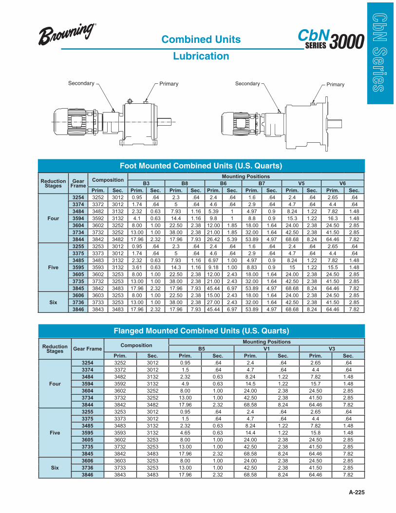
A-225
3000SERIESCbN
CbN
Serie
sCombined Units
Lubrication
Secondary Primary Secondary Primary
Foot Mounted Combined Units (U.S. Quarts)
Reduction Stages
Gear Frame
CompositionMounting Positions
B3 B8 B6 B7 V5 V6
Prim. Sec. Prim. Sec. Prim. Sec. Prim. Sec. Prim. Sec. Prim. Sec. Prim. Sec.
Four
3254 3252 3012 0.95 .64 2.3 .64 2.4 .64 1.6 .64 2.4 .64 2.65 .64
3374 3372 3012 1.74 .64 5 .64 4.6 .64 2.9 .64 4.7 .64 4.4 .64
3484 3482 3132 2.32 0.63 7.93 1.16 5.39 1 4.97 0.9 8.24 1.22 7.82 1.48
3594 3592 3132 4.1 0.63 14.4 1.16 9.8 1 8.8 0.9 15.3 1.22 16.3 1.48
3604 3602 3252 8.00 1.00 22.50 2.38 12.00 1.85 18.00 1.64 24.00 2.38 24.50 2.85
3734 3732 3252 13.00 1.00 38.00 2.38 21.00 1.85 32.00 1.64 42.50 2.38 41.50 2.85
3844 3842 3482 17.96 2.32 17.96 7.93 26.42 5.39 53.89 4.97 68.68 8.24 64.46 7.82
Five
3255 3253 3012 0.95 .64 2.3 .64 2.4 .64 1.6 .64 2.4 .64 2.65 .64
3375 3373 3012 1.74 .64 5 .64 4.6 .64 2.9 .64 4.7 .64 4.4 .64
3485 3483 3132 2.32 0.63 7.93 1.16 6.97 1.00 4.97 0.9 8.24 1.22 7.82 1.48
3595 3593 3132 3.61 0.63 14.3 1.16 9.18 1.00 8.83 0.9 15 1.22 15.5 1.48
3605 3602 3253 8.00 1.00 22.50 2.38 12.00 2.43 18.00 1.64 24.00 2.38 24.50 2.85
3735 3732 3253 13.00 1.00 38.00 2.38 21.00 2.43 32.00 1.64 42.50 2.38 41.50 2.85
3845 3842 3483 17.96 2.32 17.96 7.93 45.44 6.97 53.89 4.97 68.68 8.24 64.46 7.82
Six
3606 3603 3253 8.00 1.00 22.50 2.38 15.00 2.43 18.00 1.64 24.00 2.38 24.50 2.85
3736 3733 3253 13.00 1.00 38.00 2.38 27.00 2.43 32.00 1.64 42.50 2.38 41.50 2.85
3846 3843 3483 17.96 2.32 17.96 7.93 45.44 6.97 53.89 4.97 68.68 8.24 64.46 7.82
Flanged Mounted Combined Units (U.S. Quarts)
Reduction Stages Gear Frame
CompositionMounting Positions
B5 V1 V3
Prim. Sec. Prim. Sec. Prim. Sec. Prim. Sec.
Four
3254 3252 3012 0.95 .64 2.4 .64 2.65 .64
3374 3372 3012 1.5 .64 4.7 .64 4.4 .64
3484 3482 3132 2.32 0.63 8.24 1.22 7.82 1.48
3594 3592 3132 4.9 0.63 14.5 1.22 15.7 1.48
3604 3602 3252 8.00 1.00 24.00 2.38 24.50 2.85
3734 3732 3252 13.00 1.00 42.50 2.38 41.50 2.85
3844 3842 3482 17.96 2.32 68.58 8.24 64.46 7.82
Five
3255 3253 3012 0.95 .64 2.4 .64 2.65 .64
3375 3373 3012 1.5 .64 4.7 .64 4.4 .64
3485 3483 3132 2.32 0.63 8.24 1.22 7.82 1.48
3595 3593 3132 4.65 0.63 14.4 1.22 15.8 1.48
3605 3602 3253 8.00 1.00 24.00 2.38 24.50 2.85
3735 3732 3253 13.00 1.00 42.50 2.38 41.50 2.85
3845 3842 3483 17.96 2.32 68.58 8.24 64.46 7.82
Six
3606 3603 3253 8.00 1.00 24.00 2.38 24.50 2.85
3736 3733 3253 13.00 1.00 42.50 2.38 41.50 2.85
3846 3843 3483 17.96 2.32 68.58 8.24 64.46 7.82