Machine Safeguarding Products - PREVENTA™ XPS Safety ...
72
Catalog 03 Machine Safeguarding Products PREVENTA™ XPS Safety Relays Supplement File 9007 CONTENTS Description Page Selection Guide . . . . . . . . . . . . . . . . . . . . . . . . . . . . . . . . . . . . . . . . . . . . . . . . . . 2-10 General Ratings . . . . . . . . . . . . . . . . . . . . . . . . . . . . . . . . . . . . . . . . . . . . . . . . . 11-12 XPSAC . . . . . . . . . . . . . . . . . . . . . . . . . . . . . . . . . . . . . . . . . . . . . . . . . . . . . . . . 13-15 XPSAV, XPSAT. . . . . . . . . . . . . . . . . . . . . . . . . . . . . . . . . . . . . . . . . . . . . . . . . . 16-22 XPSAF . . . . . . . . . . . . . . . . . . . . . . . . . . . . . . . . . . . . . . . . . . . . . . . . . . . . . . . . 23-26 XPSAFL . . . . . . . . . . . . . . . . . . . . . . . . . . . . . . . . . . . . . . . . . . . . . . . . . . . . . . . 27-29 XPSAR . . . . . . . . . . . . . . . . . . . . . . . . . . . . . . . . . . . . . . . . . . . . . . . . . . . . . . . . 30-35 XPSBA, XPSBC, XPSBF . . . . . . . . . . . . . . . . . . . . . . . . . . . . . . . . . . . . . . . . . . 36-42 XPSTSA, XPSTSW . . . . . . . . . . . . . . . . . . . . . . . . . . . . . . . . . . . . . . . . . . . . . . 43-46 XPSDMB, XPSDME . . . . . . . . . . . . . . . . . . . . . . . . . . . . . . . . . . . . . . . . . . . . . . 47-52 XPSCM. . . . . . . . . . . . . . . . . . . . . . . . . . . . . . . . . . . . . . . . . . . . . . . . . . . . . . . . 53-59 XPSMP. . . . . . . . . . . . . . . . . . . . . . . . . . . . . . . . . . . . . . . . . . . . . . . . . . . . . . . . 60-69 Dimensions. . . . . . . . . . . . . . . . . . . . . . . . . . . . . . . . . . . . . . . . . . . . . . . . . . . . . . . . 70
-
Upload
khangminh22 -
Category
Documents
-
view
0 -
download
0
Transcript of Machine Safeguarding Products - PREVENTA™ XPS Safety ...
Catalog
03
Machine Safeguarding ProductsPREVENTA™ XPS Safety RelaysSupplement
File 9007
CONTENTS
Description PageSelection Guide . . . . . . . . . . . . . . . . . . . . . . . . . . . . . . . . . . . . . . . . . . . . . . . . . . 2-10General Ratings . . . . . . . . . . . . . . . . . . . . . . . . . . . . . . . . . . . . . . . . . . . . . . . . . 11-12XPSAC . . . . . . . . . . . . . . . . . . . . . . . . . . . . . . . . . . . . . . . . . . . . . . . . . . . . . . . . 13-15XPSAV, XPSAT. . . . . . . . . . . . . . . . . . . . . . . . . . . . . . . . . . . . . . . . . . . . . . . . . . 16-22XPSAF . . . . . . . . . . . . . . . . . . . . . . . . . . . . . . . . . . . . . . . . . . . . . . . . . . . . . . . . 23-26XPSAFL . . . . . . . . . . . . . . . . . . . . . . . . . . . . . . . . . . . . . . . . . . . . . . . . . . . . . . . 27-29XPSAR . . . . . . . . . . . . . . . . . . . . . . . . . . . . . . . . . . . . . . . . . . . . . . . . . . . . . . . . 30-35XPSBA, XPSBC, XPSBF . . . . . . . . . . . . . . . . . . . . . . . . . . . . . . . . . . . . . . . . . . 36-42XPSTSA, XPSTSW . . . . . . . . . . . . . . . . . . . . . . . . . . . . . . . . . . . . . . . . . . . . . . 43-46XPSDMB, XPSDME . . . . . . . . . . . . . . . . . . . . . . . . . . . . . . . . . . . . . . . . . . . . . . 47-52XPSCM. . . . . . . . . . . . . . . . . . . . . . . . . . . . . . . . . . . . . . . . . . . . . . . . . . . . . . . . 53-59XPSMP. . . . . . . . . . . . . . . . . . . . . . . . . . . . . . . . . . . . . . . . . . . . . . . . . . . . . . . . 60-69Dimensions. . . . . . . . . . . . . . . . . . . . . . . . . . . . . . . . . . . . . . . . . . . . . . . . . . . . . . . . 70
PREVENTA™ XPS Safety RelaysSelection Guide
2
Applications
Modules
Conformity to standards
Product CE
Machine assemblies E
Product certifications U
Number of circuits
Safety 3
Additional 1
Display 2
Supply voltage2412
Synchronization time between inputs
U
Input channel voltage
24 V / 48 V version 2
115 V/230 V versionor 110 V/120 V/230 V
1
Module type X
Pages 1
Selection Guide
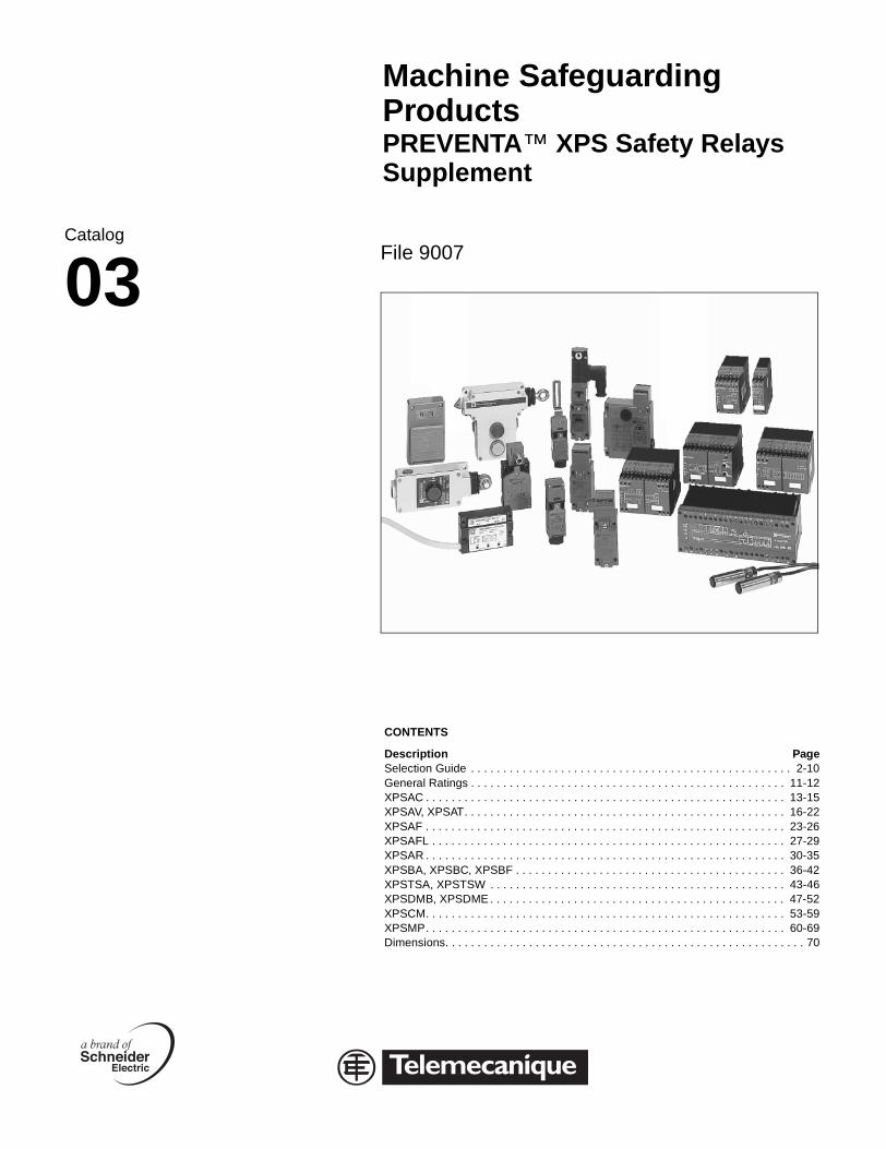
NOTE: Safety systems are comprised of many components. No one safety component will insure the safety of the system. The design of the complete safety system should be considered before beginning. It is very important to follow all applicable safety standards when installing and wiring these components.
For Emergency stop and limit switch monitoring
ategory 3 conforming to EN 60954-1N 61088
Category 4 conforming to EN 60954-1 (instantaneous break contacts)Category 3 conforming to EN 60954-1 (time delay break contacts)EN 61088
Category 4 conforming to EN 60954-1EN 61088
N 60292, EN 60418, IEC/EN 60204-1
L, CSA, CE
N.O. 3 N.O. instantaneous break 2 N.O. time delay break
3 N.O. instantaneous break 3 N.O. time delay break
solid-state 1 N.C. 3 solid-state outputs for signalling to PLC
LEDs 4 LEDs 11 LEDs
4 Vac/dc8 Vac15 Vac30 Vac
24 Vac/dc115 Vac230 Vac
24 Vdc
nlimited 75 ms (when wired for automatic start)
Unlimited or 1.5 secondsdepending on wiring
4 Vac/dc / 48 Vac 24 Vdc / – 24 Vdc / –
15 Vac / 230 Vac 48 Vdc / 48 Vdc – / –
PSAC XPSAT XPSAV
3 to 15 16 to 22
© 2003 Schneider Electric All Rights Reserved 05/03
PREVENTA™ XPS Safety RelaysSelection Guide
05/03
Applications
Modules Fm
Conformity to standards
Product CaEN
Machine assemblies EN
Product certifications UL
Number of circuits
Safety 3 N
Additional –
Display 3 L
Supply voltage 24
Synchronization time between inputs
Un
Input channel voltage
24 V / 48 V version 24
115 V/230 V versionor 110 V/120 V/230 V
–
Module type XP
Pages 23
Selection Guide
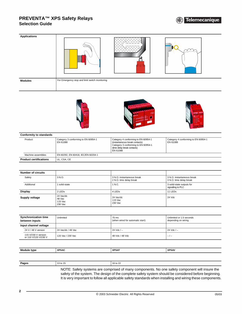
or Emergency stop and limit switch onitoring
For Emergency stop, limit switch and solid-state output light curtain monitoring
For Emergency stop, limit switch, safety mat and safety edge and solid-state output light curtain monitoring
tegory 4 conforming to EN 60954-1 61088
Category 3 conforming to EN 60954-1EN 61088EN 61496-1 (type 4)
Category 4 conforming to EN 60954-1EN 61088EN 61496-1 (type 4)
Category 4 conforming to EN 60954-1EN 61088EN 61760EN 61496-1 (type 4)
60292, EN 60418, IEC/EN 60204-1
, CSA, CE
.O. 7 N.O. 3 N.O.
2 N.C. + 4 solid-state outputsfor signalling to PLC
1 N.C. + 4 solid-state outputsfor signalling to PLC
EDs 4 LEDs 4 LEDs
Vac/dc 24 Vac/dc115 Vac230 Vac
24 Vac/dc120 Vac and 24 Vdc230 Vac and 24 Vdc
limited100 ms
Unlimited or 2 seconds, 4 secondsdepending on wiring
Vdc / – 24 Vdc / –
24 Vdc / 24 Vdc 24 Vdc / 24 Vdc
SAF XPSAFL XPSAR XPSAK
to 26 27 to 29 30 to 35 See Catalog 9007CT0002
3© 2003 Schneider Electric All Rights Reserved
PREVENTA™ XPS Safety RelaysSelection Guide
4
Applications
Modules F
Conformity to standards
Product CE
Machine assemblies EI
Product certifications U
Number of circuits
Safety 3
Additional 1
Display 3
Supply Voltage 2412
Synchronization time between inputs
1
Input channel voltage
24 V / 48 V version 2
115 V/230 V version 4
Module type X
Pages S
Selection Guide
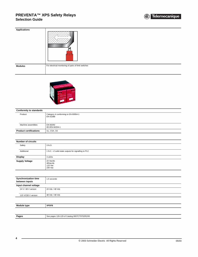
or electrical monitoring of pairs of limit switches
ategory 4 conforming to EN 60954-1N 61088
N 60292EC/EN 60204-1
L, CSA, CE
N.O.
N.C. +2 solid-state outputs for signalling to PLC
LEDs
4 Vac/dc8Vac/dc15 Vac30 Vac
.5 seconds
4 Vdc / 48 Vdc
8 Vdc / 48 Vdc
PSFB
ee pages 126-129 of Catalog 9007CT9702R2/00
© 2003 Schneider Electric All Rights Reserved 05/03
PREVENTA™ XPS Safety RelaysSelection Guide
05/03
Applications
Modules F
Conformity to standards
ProductCE
Machine assembliesEI
Product certifications U
Number of circuits
Safety 1
Additional 1
Display 2
Supply voltage212
Synchronization time between inputs
5
Input channel voltage
24 V / 48 V version2
115 V/230 V version 2
Module type X
Pages 3
Selection Guide
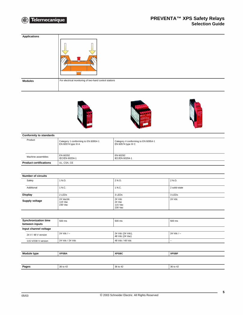
or electrical monitoring of two-hand control stations
ategory 1 conforming to EN 60954-1N 60574 type III A
Category 4 conforming to EN 60954-1EN 60574 type III C
N 60292EC/EN 60204-1
EN 60292IEC/EN 60204-1
L, CSA, CE
N.O. 2 N.O. 2 N.O.
N.C. 1 N.C. 2 solid-state
LEDs 3 LEDs 3 LEDs
4 Vac/dc15 Vac30 Vac
24 Vdc24 Vac115 Vac230 Vac
24 Vdc
00 ms 500 ms 500 ms
4 Vdc / – 24 Vdc (24 Vdc), 48 Vdc (24 Vac)
24 Vdc / –
4 Vdc / 24 Vdc 48 Vdc / 48 Vdc –
PSBA XPSBC XPSBF
6 to 42 36 to 42 36 to 42
5© 2003 Schneider Electric All Rights Reserved
PREVENTA™ XPS Safety RelaysSelection Guide
6
Applications
Modules
Functions
Conformity to standards
Product
Machine assemblies
Product certifications
Number of circuits
Safety
Additional
Display
Supply voltage
Module type
Pages
Selection Guide
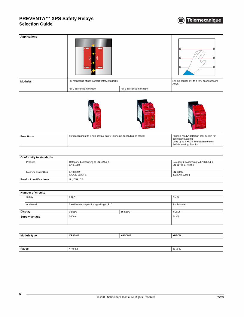
For monitoring of non-contact safety interlocks For the control of 1 to 4 thru-beam sensors XU2S
For 2 interlocks maximum For 6 interlocks maximum
For monitoring 2 to 6 non-contact safety interlocks depending on model Forms a “body” detection light curtain for perimeter guarding. Uses up to 4 XU2S thru-beam sensorsBuilt-in “muting” function
Category 4 conforming to EN 60954-1EN 61088
Category 2 conforming to EN 60954-1EN 61496-1 - type 2
EN 60292IEC/EN 60204-1
EN 60292IEC/EN 60204-1
UL, CSA, CE
2 N.O. 2 N.O.
2 solid-state outputs for signalling to PLC 4 solid-state
3 LEDs 15 LEDs 4 LEDs
24 Vdc 24 Vdc
XPSDMB XPSDME XPSCM
47 to 52 53 to 59
© 2003 Schneider Electric All Rights Reserved 05/03
PREVENTA™ XPS Safety RelaysSelection Guide
05/03
Applications
Modules F
Functions A
Conformity to standards
Product CE
Machine assemblies EI
Product certifications U
Number of circuits
Safety 4
Additional 1
Display 3
Supply voltage 212
Module type X
Pages S
Selection Guide
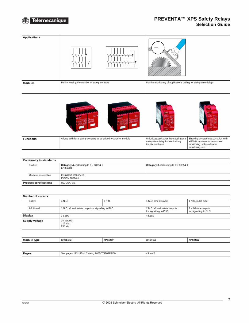
or increasing the number of safety contacts For the monitoring of applications calling for safety time delays
llows additional safety contacts to be added to another module Unlocks guards after the elapsing of a safety time delay for interlocking inertia machines
Shunting contact in association with XPSVN modules for zero speed monitoring, solenoid valve monitoring, etc.
ategory 4 conforming to EN 60954-1N 61088
Category 3 conforming to EN 60954-1
N 60292, EN 60418EC/EN 60204-1
L, CSA, CE
N.O. 8 N.O. 1 N.O. time delayed 1 N.O. pulse type
N.C. +1 solid-state output for signalling to PLC 2 N.C. +2 solid-state outputs for signalling to PLC
2 solid-state outputsfor signalling to PLC
LEDs 4 LEDs
4 Vac/dc15 Vac30 Vac
PSECM XPSECP XPSTSA XPSTSW
ee pages 122-125 of Catalog 9007CT9702R2/00 43 to 46
7© 2003 Schneider Electric All Rights Reserved
PREVENTA™ XPS Safety RelaysSelection Guide
8
Applications
Modules
Functions
Conformity to standards
Product
Machine assemblies
Product certifications
Number of circuits
Safety
Additional
Display
Supply voltage
Module type
Pages
Selection Guide
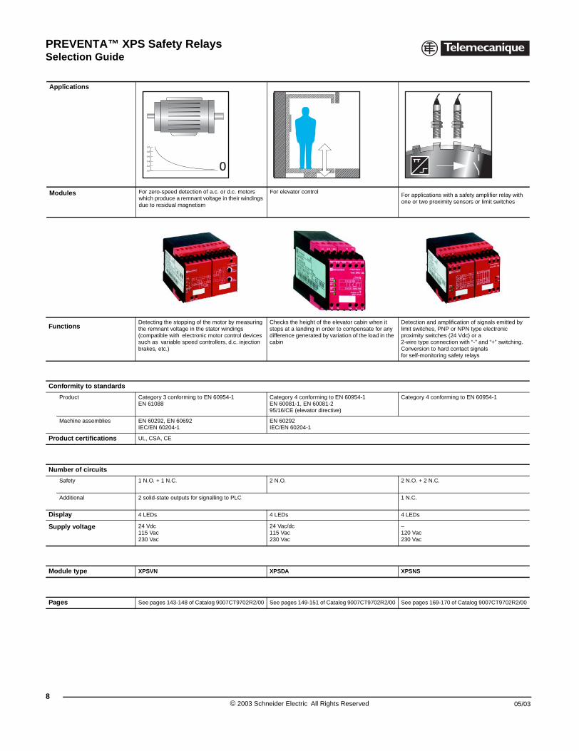
For zero-speed detection of a.c. or d.c. motors which produce a remnant voltage in their windings due to residual magnetism
For elevator controlFor applications with a safety amplifier relay with one or two proximity sensors or limit switches
Detecting the stopping of the motor by measuring the remnant voltage in the stator windings (compatible with electronic motor control devices such as variable speed controllers, d.c. injection brakes, etc.)
Checks the height of the elevator cabin when it stops at a landing in order to compensate for any difference generated by variation of the load in the cabin
Detection and amplification of signals emitted by limit switches, PNP or NPN type electronic proximity switches (24 Vdc) or a 2-wire type connection with “-” and “+” switching. Conversion to hard contact signals for self-monitoring safety relays
Category 3 conforming to EN 60954-1EN 61088
Category 4 conforming to EN 60954-1EN 60081-1, EN 60081-295/16/CE (elevator directive)
Category 4 conforming to EN 60954-1
EN 60292, EN 60692IEC/EN 60204-1
EN 60292IEC/EN 60204-1
UL, CSA, CE
1 N.O. + 1 N.C. 2 N.O. 2 N.O. + 2 N.C.
2 solid-state outputs for signalling to PLC 1 N.C.
4 LEDs 4 LEDs 4 LEDs
24 Vdc115 Vac230 Vac
24 Vac/dc115 Vac230 Vac
–120 Vac230 Vac
XPSVN XPSDA XPSNS
See pages 143-148 of Catalog 9007CT9702R2/00 See pages 149-151 of Catalog 9007CT9702R2/00 See pages 169-170 of Catalog 9007CT9702R2/00
0,0
0,2
0,4
0,6
0,8
1,0
0
© 2003 Schneider Electric All Rights Reserved 05/03
PREVENTA™ XPS Safety RelaysSelection Guide
05/03
Applications
Modules Fl
FunctionsDvlto
Conformity to standards
Product C
Machine assemblies EI
Product certifications U
Number of circuits
Safety 2
Additional –
Display 8
Supply voltage 2
Module type X
Pages S
Selection Guide
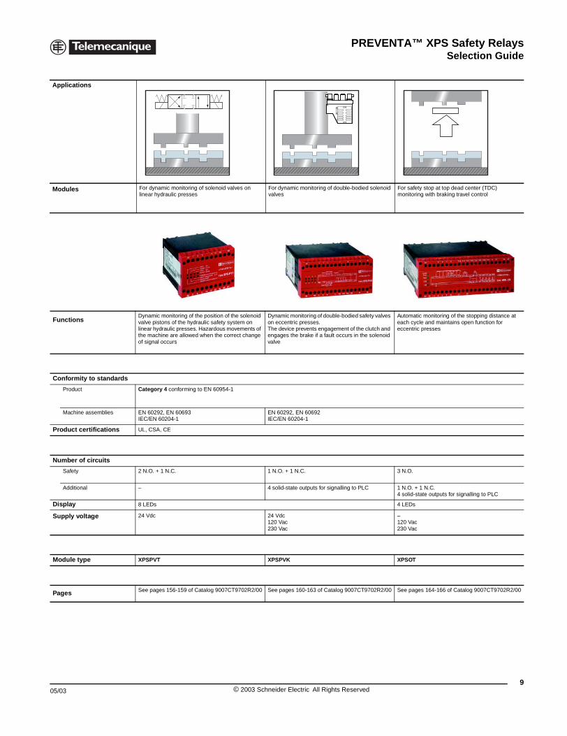
or dynamic monitoring of solenoid valves on inear hydraulic presses
For dynamic monitoring of double-bodied solenoid valves
For safety stop at top dead center (TDC) monitoring with braking travel control
ynamic monitoring of the position of the solenoid alve pistons of the hydraulic safety system on inear hydraulic presses. Hazardous movements of he machine are allowed when the correct change f signal occurs
Dynamic monitoring of double-bodied safety valves on eccentric presses. The device prevents engagement of the clutch and engages the brake if a fault occurs in the solenoid valve
Automatic monitoring of the stopping distance at each cycle and maintains open function for eccentric presses
ategory 4 conforming to EN 60954-1
N 60292, EN 60693EC/EN 60204-1
EN 60292, EN 60692IEC/EN 60204-1
L, CSA, CE
N.O. + 1 N.C. 1 N.O. + 1 N.C. 3 N.O.
4 solid-state outputs for signalling to PLC 1 N.O. + 1 N.C.4 solid-state outputs for signalling to PLC
LEDs 4 LEDs
4 Vdc 24 Vdc120 Vac230 Vac
–120 Vac230 Vac
PSPVT XPSPVK XPSOT
ee pages 156-159 of Catalog 9007CT9702R2/00 See pages 160-163 of Catalog 9007CT9702R2/00 See pages 164-166 of Catalog 9007CT9702R2/00
9© 2003 Schneider Electric All Rights Reserved
PREVENTA™ XPS Safety RelaysSelection Guide
10
Applications
Modules
Functions
Conformity to standards
Product
Machine assemblies
Product certifications
Number of circuits
Safety
Additional
Display
Supply voltage
Module type
Pages
Selection Guide
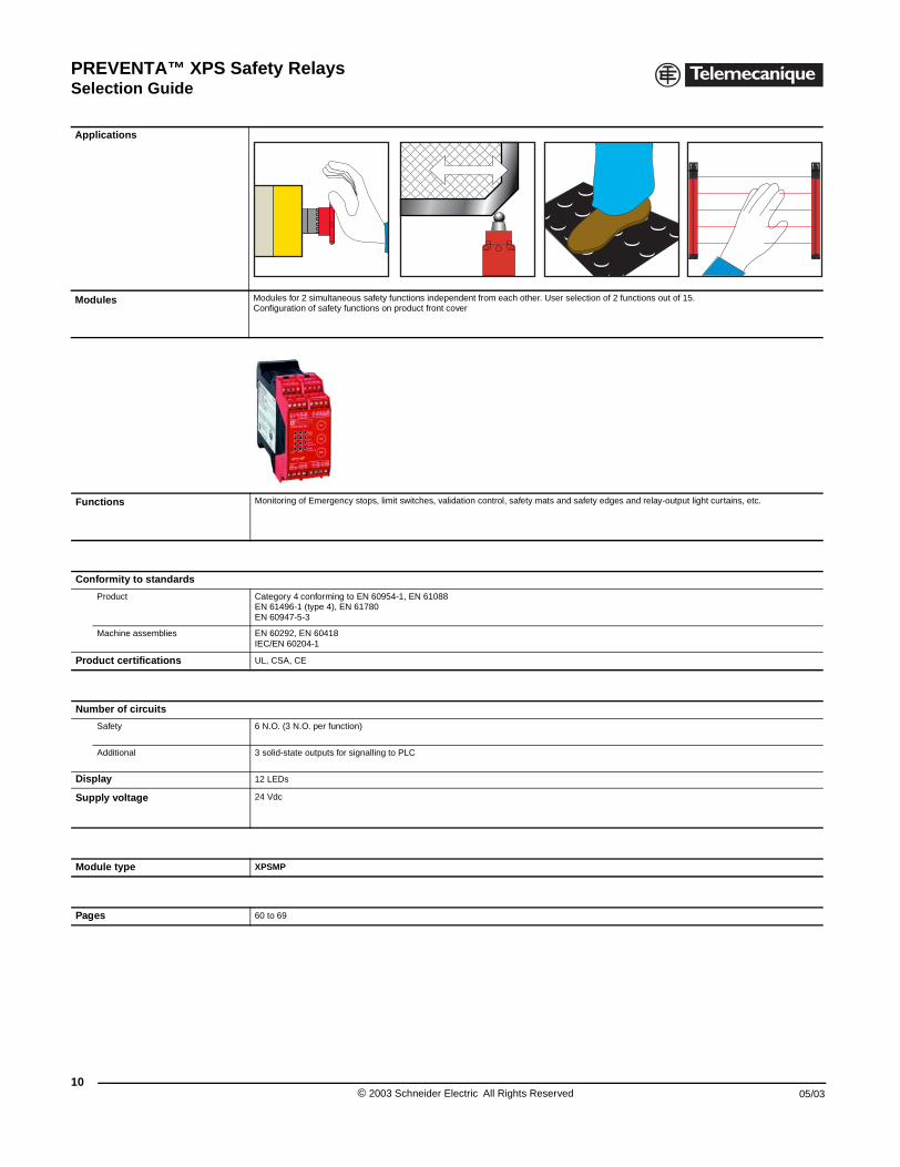
Modules for 2 simultaneous safety functions independent from each other. User selection of 2 functions out of 15. Configuration of safety functions on product front cover
Monitoring of Emergency stops, limit switches, validation control, safety mats and safety edges and relay-output light curtains, etc.
Category 4 conforming to EN 60954-1, EN 61088EN 61496-1 (type 4), EN 61780EN 60947-5-3
EN 60292, EN 60418IEC/EN 60204-1
UL, CSA, CE
6 N.O. (3 N.O. per function)
3 solid-state outputs for signalling to PLC
12 LEDs
24 Vdc
XPSMP
60 to 69
© 2003 Schneider Electric All Rights Reserved 05/03
PREVENTA™ XPS Safety RelaysGeneral Rating Curves
05/03
XPSAL, XPSAC, XPSAT (time delayXPSCM, XPSDA, XPSFB, XPSNS,
XPSAF, XPSAK, XPSAFL
XPSAR
Sw
itchi
ng c
urre
nt (
A)
10
1
0,11104
AC 15: 230 V
DC 13: 24 V
Sw
itchi
ng c
urre
nt (
A)
10
1
0,1104
AC
DC
Sw
itchi
ng c
urre
nt (
A)
10
4
3
2
5
6789
110
DC 13: 24 V
General Rating Curve
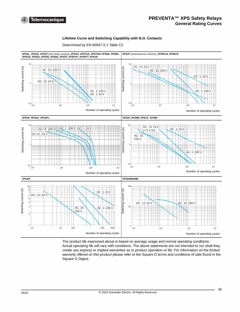
Lifetime Curve and Switching Capability with N.O. Contacts
Determined by EN 60947-5-1 Table C2
The product life expressed above is based on average usage and normal operating conditions. Actual operating life will vary with conditions. The above statements are not intended to nor shall they create any express or implied warranties as to product operation or life. For information on the limited warranty offered on this product please refer to the Square D terms and conditions of sale found in the Square D Digest.
contacts), XPSAX, XPSTSA, XPSTSW, XPSBA, XPSBC, XPSOT, XPSPVK, XPSPVT, XPSVN
XPSAT (instantaneous contacts), XPSECM, XPSECP
XPSAV, XPSMP, XPSVC, XPSBF
XPSDMB/DME
Number of operating cycles
10710605
AC 1: 230 VDC 1: 24 V
Sw
itchi
ng c
urre
nt (
A)
Number of operating cycles
10
1
0,1106 107105104
DC 13: 24 VAC 15: 230 V
DC 1: 24 V
AC 1: 230 V
Number of operating cycles
107106105
AC DC
Sw
itchi
ng c
urre
nt (
A)
Number of operating cycles
10
1
0,1106 107105104
AC 15: 230 V
DC 13: 24 V(< 0.1 Hz) DC 1: 24 V
AC 1: 230 V
Number of operating cycles
50 100 1000500
AC 15: 230 V
DC 1: 24 V
AC 1: 230 V
Sw
itchi
ng c
urre
nt (
A)
Number of operating cycles
107106105104
10
1
100
DC 13: 24 V AC 15: 230 V
11© 2003 Schneider Electric All Rights Reserved
PREVENTA™ XPS Safety RelaysGeneral Electrical Ratings
12
General Electrical Ratings
Ie: Operational current measured. Cos ϕ: Power factor.Ue: Operational voltage measured. T 0.95: Time taken to reach 95% of rated current.
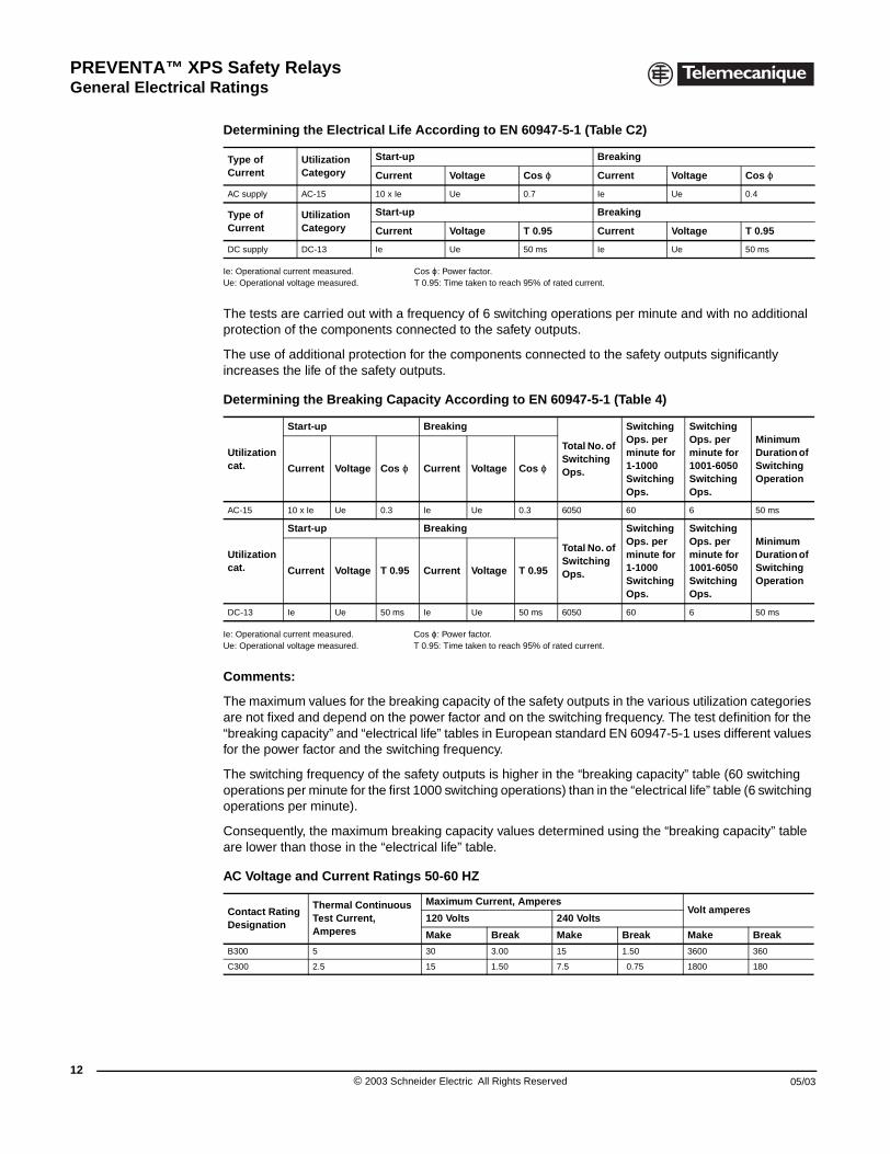
The tests are carried out with a frequency of 6 switching operations per minute and with no additional protection of the components connected to the safety outputs.
The use of additional protection for the components connected to the safety outputs significantly increases the life of the safety outputs.
Ie: Operational current measured. Cos ϕ: Power factor.Ue: Operational voltage measured. T 0.95: Time taken to reach 95% of rated current.
Comments:
The maximum values for the breaking capacity of the safety outputs in the various utilization categories are not fixed and depend on the power factor and on the switching frequency. The test definition for the “breaking capacity” and “electrical life” tables in European standard EN 60947-5-1 uses different values for the power factor and the switching frequency.
The switching frequency of the safety outputs is higher in the “breaking capacity” table (60 switching operations per minute for the first 1000 switching operations) than in the “electrical life” table (6 switching operations per minute).
Consequently, the maximum breaking capacity values determined using the “breaking capacity” table are lower than those in the “electrical life” table.
Determining the Electrical Life According to EN 60947-5-1 (Table C2)
Type of Current
Utilization Category
Start-up Breaking
Current Voltage Cos ϕ Current Voltage Cos ϕ
AC supply AC-15 10 x Ie Ue 0.7 Ie Ue 0.4
Type of Current
Utilization Category
Start-up Breaking
Current Voltage T 0.95 Current Voltage T 0.95
DC supply DC-13 Ie Ue 50 ms Ie Ue 50 ms
Determining the Breaking Capacity According to EN 60947-5-1 (Table 4)
Utilizationcat.
Start-up Breaking
Total No. of SwitchingOps.
Switching Ops. per minute for 1-1000 Switching Ops.
Switching Ops. per minute for 1001-6050 Switching Ops.
Minimum Duration of Switching Operation
Current Voltage Cos ϕ Current Voltage Cos ϕ
AC-15 10 x Ie Ue 0.3 Ie Ue 0.3 6050 60 6 50 ms
Utilizationcat.
Start-up Breaking
Total No. of Switching Ops.
Switching Ops. per minute for 1-1000 Switching Ops.
Switching Ops. per minute for 1001-6050 Switching Ops.
Minimum Duration of Switching Operation
Current Voltage T 0.95 Current Voltage T 0.95
DC-13 Ie Ue 50 ms Ie Ue 50 ms 6050 60 6 50 ms
AC Voltage and Current Ratings 50-60 HZ
Contact Rating Designation
Thermal Continuous Test Current, Amperes
Maximum Current, AmperesVolt amperes
120 Volts 240 Volts
Make Break Make Break Make Break
B300 5 30 3.00 15 1.50 3600 360
C300 2.5 15 1.50 7.5 0.75 1800 180
© 2003 Schneider Electric All Rights Reserved 05/03
PREVENTA™ XPS Safety RelaysEmergency stop and limit switch monitoring
05/03
XPSAC Safety modules for emergency stop and limit switch monitoring
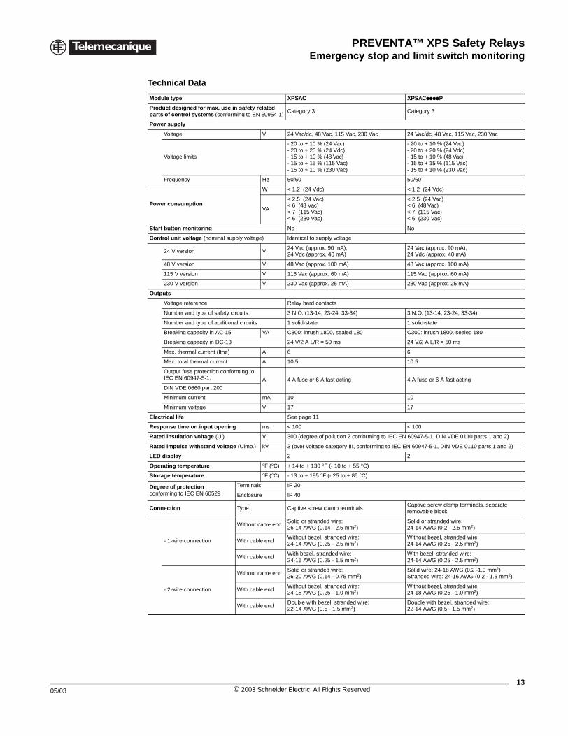
Technical Data
Module type XPSAC XPSACppppP
Product designed for max. use in safety related parts of control systems (conforming to EN 60954-1)
Category 3 Category 3
Power supply
Voltage V 24 Vac/dc, 48 Vac, 115 Vac, 230 Vac 24 Vac/dc, 48 Vac, 115 Vac, 230 Vac
Voltage limits
- 20 to + 10 % (24 Vac)- 20 to + 20 % (24 Vdc)- 15 to + 10 % (48 Vac)- 15 to + 15 % (115 Vac)- 15 to + 10 % (230 Vac)
- 20 to + 10 % (24 Vac)- 20 to + 20 % (24 Vdc)- 15 to + 10 % (48 Vac)- 15 to + 15 % (115 Vac)- 15 to + 10 % (230 Vac)
Frequency Hz 50/60 50/60
Power consumption
W < 1.2 (24 Vdc) < 1.2 (24 Vdc)
VA
< 2.5 (24 Vac)< 6 (48 Vac)< 7 (115 Vac)< 6 (230 Vac)
< 2.5 (24 Vac)< 6 (48 Vac)< 7 (115 Vac)< 6 (230 Vac)
Start button monitoring No No
Control unit voltage (nominal supply voltage) Identical to supply voltage
24 V version V24 Vac (approx. 90 mA), 24 Vdc (approx. 40 mA)
24 Vac (approx. 90 mA), 24 Vdc (approx. 40 mA)
48 V version V 48 Vac (approx. 100 mA) 48 Vac (approx. 100 mA)
115 V version V 115 Vac (approx. 60 mA) 115 Vac (approx. 60 mA)
230 V version V 230 Vac (approx. 25 mA) 230 Vac (approx. 25 mA)
Outputs
Voltage reference Relay hard contacts
Number and type of safety circuits 3 N.O. (13-14, 23-24, 33-34) 3 N.O. (13-14, 23-24, 33-34)
Number and type of additional circuits 1 solid-state 1 solid-state
Breaking capacity in AC-15 VA C300: inrush 1800, sealed 180 C300: inrush 1800, sealed 180
Breaking capacity in DC-13 24 V/2 A L/R = 50 ms 24 V/2 A L/R = 50 ms
Max. thermal current (Ithe) A 6 6
Max. total thermal current A 10.5 10.5
Output fuse protection conforming to IEC EN 60947-5-1, A 4 A fuse or 6 A fast acting 4 A fuse or 6 A fast acting
DIN VDE 0660 part 200
Minimum current mA 10 10
Minimum voltage V 17 17
Electrical life See page 11
Response time on input opening ms < 100 < 100
Rated insulation voltage (Ui) V 300 (degree of pollution 2 conforming to IEC EN 60947-5-1, DIN VDE 0110 parts 1 and 2)
Rated impulse withstand voltage (Uimp.) kV 3 (over voltage category III, conforming to IEC EN 60947-5-1, DIN VDE 0110 parts 1 and 2)
LED display 2 2
Operating temperature °F (°C) + 14 to + 130 °F (- 10 to + 55 °C)
Storage temperature °F (°C) - 13 to + 185 °F (- 25 to + 85 °C)
Degree of protectionconforming to IEC EN 60529
Terminals IP 20
Enclosure IP 40
Connection Type Captive screw clamp terminalsCaptive screw clamp terminals, separate removable block
- 1-wire connection
Without cable endSolid or stranded wire: 26-14 AWG (0.14 - 2.5 mm2)
Solid or stranded wire: 24-14 AWG (0.2 - 2.5 mm2)
With cable endWithout bezel, stranded wire: 24-14 AWG (0.25 - 2.5 mm2)
Without bezel, stranded wire: 24-14 AWG (0.25 - 2.5 mm2)
With cable endWith bezel, stranded wire: 24-16 AWG (0.25 - 1.5 mm2)
With bezel, stranded wire: 24-14 AWG (0.25 - 2.5 mm2)
- 2-wire connection
Without cable endSolid or stranded wire: 26-20 AWG (0.14 - 0.75 mm2)
Solid wire: 24-18 AWG (0.2 -1.0 mm2)Stranded wire: 24-16 AWG (0.2 - 1.5 mm2)
With cable endWithout bezel, stranded wire: 24-18 AWG (0.25 - 1.0 mm2)
Without bezel, stranded wire: 24-18 AWG (0.25 - 1.0 mm2)
With cable endDouble with bezel, stranded wire: 22-14 AWG (0.5 - 1.5 mm2)
Double with bezel, stranded wire: 22-14 AWG (0.5 - 1.5 mm2)
13© 2003 Schneider Electric All Rights Reserved
PREVENTA™ XPS Safety RelaysEmergency stop and limit switch monitoring
14
®
XPSACppppP
File E164353CCN NKCR
File LR44087Class 3211 03
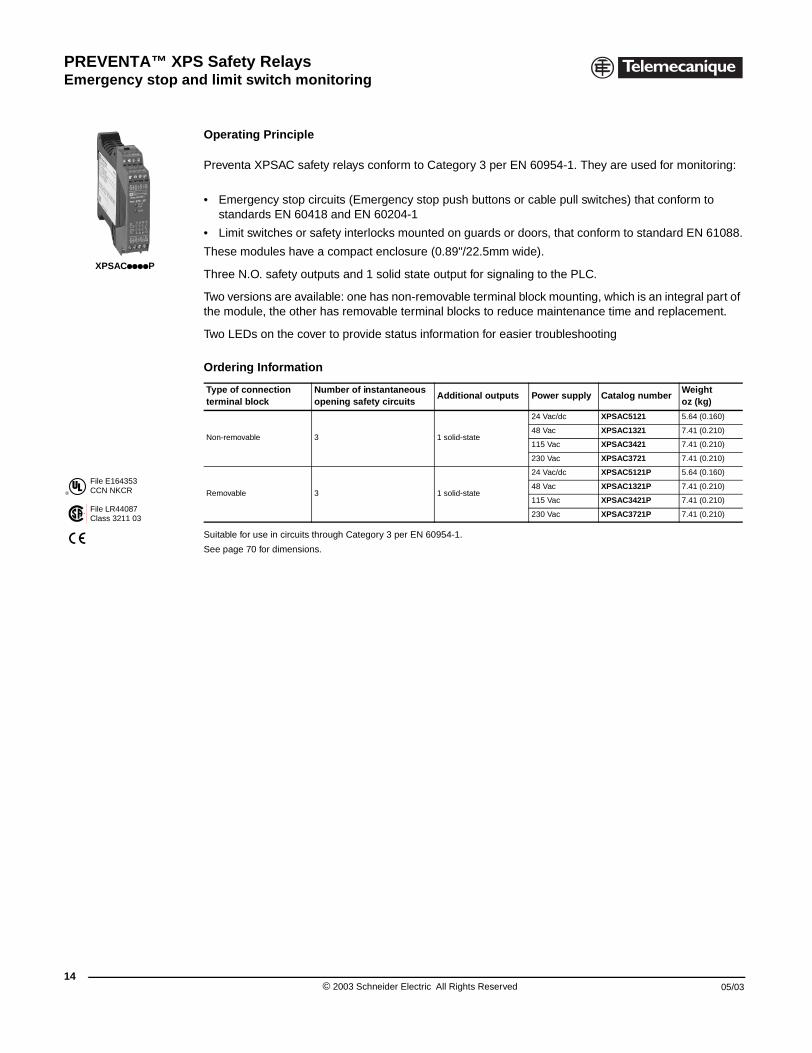
XPSAC Safety modules for emergency stop and limit switch monitoring
Operating Principle
Preventa XPSAC safety relays conform to Category 3 per EN 60954-1. They are used for monitoring:
• Emergency stop circuits (Emergency stop push buttons or cable pull switches) that conform to standards EN 60418 and EN 60204-1
• Limit switches or safety interlocks mounted on guards or doors, that conform to standard EN 61088.
These modules have a compact enclosure (0.89"/22.5mm wide).
Three N.O. safety outputs and 1 solid state output for signaling to the PLC.
Two versions are available: one has non-removable terminal block mounting, which is an integral part of the module, the other has removable terminal blocks to reduce maintenance time and replacement.
Two LEDs on the cover to provide status information for easier troubleshooting
Suitable for use in circuits through Category 3 per EN 60954-1.
See page 70 for dimensions.
Ordering Information
Type of connection terminal block
Number of instantaneous opening safety circuits
Additional outputs Power supply Catalog numberWeightoz (kg)
Non-removable 3 1 solid-state
24 Vac/dc XPSAC5121 5.64 (0.160)
48 Vac XPSAC1321 7.41 (0.210)
115 Vac XPSAC3421 7.41 (0.210)
230 Vac XPSAC3721 7.41 (0.210)
Removable 3 1 solid-state
24 Vac/dc XPSAC5121P 5.64 (0.160)
48 Vac XPSAC1321P 7.41 (0.210)
115 Vac XPSAC3421P 7.41 (0.210)
230 Vac XPSAC3721P 7.41 (0.210)
© 2003 Schneider Electric All Rights Reserved 05/03
PREVENTA™ XPS Safety RelaysEmergency stop and limit switch monitoring
05/03
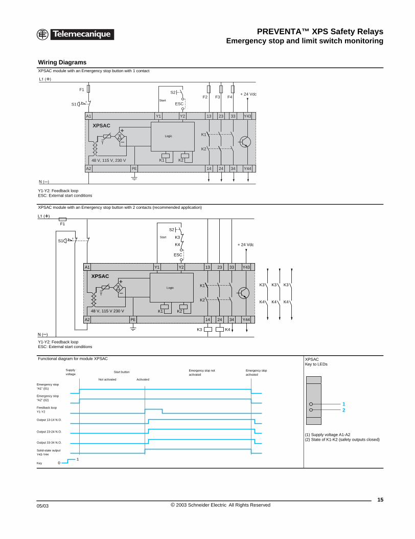
Wiring DiagramsXPSAC module with an Emergency
Y1-Y2: Feedback loopESC: External start conditions
XPSAC module with an Emergency
Y1-Y2: Feedback loopESC: External start conditions
Functional diagram for module XPS
S1
A1
A2
F1
48 V,
T
XPS
S1
A1
A2
F1
48 V, 1
T
XPSA
01
Key
Supplyvoltage
Emergency stop“A2” (02)
Output 23-24 N.O.
Emergency stop“A1” (01)
Feedback loopY1-Y2
Output 13-14 N.O.
Output 33-34 N.O.
Solid-state output Y43-Y44
No
XPSAC Safety modules for emergency stop and limit switch monitoring
stop button with 1 contact
stop button with 2 contacts (recommended application)
AC XPSACKey to LEDs
(1) Supply voltage A1-A2(2) State of K1-K2 (safety outputs closed)
S2
23 33Y2 13
PE 14 24 34
Y43
Y44
Y1
F2 F3 F4
K2K1115 V, 230 V
K1
K2
ESC
AC
+ 24 Vdc
Start
Logic
S2
K3
K4
K3
K4
K3
K4
K3
K4
23 33Y2 13
PE 14 24 34
Y43
Y44
Y1
K2K115 V 230 V
K1
K2
ESC
K4K3
C
+ 24 Vdc
Start
Logic
Emergency stopactivated
Emergency stop not activated
Start button
t activated Activated
12
15© 2003 Schneider Electric All Rights Reserved
PREVENTA™ XPS Safety RelaysEmergency stop and limit switch monitoring
16
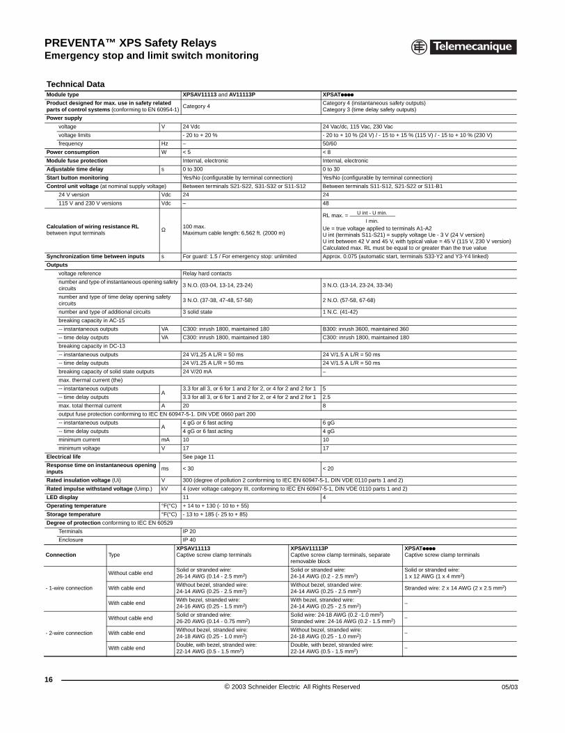
Technical DataModule type
Product designed for max. use inparts of control systems (conformi
Power supply
voltage
voltage limits
frequency
Power consumption
Module fuse protection
Adjustable time delay
Start button monitoring
Control unit voltage (at nominal su
24 V version
115 V and 230 V versions
Calculation of wiring resistance Rbetween input terminals
Synchronization time between inp
Outputs
voltage reference
number and type of instantaneocircuits
number and type of time delay circuits
number and type of additional c
breaking capacity in AC-15
-- instantaneous outputs
-- time delay outputs
breaking capacity in DC-13
-- instantaneous outputs
-- time delay outputs
breaking capacity of solid state
max. thermal current (the)
-- instantaneous outputs
-- time delay outputs
max. total thermal current
output fuse protection conform
-- instantaneous outputs
-- time delay outputs
minimum current
minimum voltage
Electrical life
Response time on instantaneous inputs
Rated insulation voltage (Ui)
Rated impulse withstand voltage
LED display
Operating temperature
Storage temperature
Degree of protection conforming to
Terminals
Enclosure
Connection Type
- 1-wire connection
Without ca
With cable
With cable
- 2-wire connection
Without ca
With cable
With cable
XPSAV and XPSAT Safety modules for emergency stop and switch monitoring
XPSAV11113 and AV11113P XPSATpppp
safety related ng to EN 60954-1)
Category 4 Category 4 (instantaneous safety outputs)Category 3 (time delay safety outputs)
V 24 Vdc 24 Vac/dc, 115 Vac, 230 Vac
- 20 to + 20 % - 20 to + 10 % (24 V) / - 15 to + 15 % (115 V) / - 15 to + 10 % (230 V)
Hz – 50/60
W < 5 < 8
Internal, electronic Internal, electronic
s 0 to 300 0 to 30
Yes/No (configurable by terminal connection) Yes/No (configurable by terminal connection)
pply voltage) Between terminals S21-S22, S31-S32 or S11-S12 Between terminals S11-S12, S21-S22 or S11-B1
Vdc 24 24
Vdc – 48
L Ω 100 max.Maximum cable length: 6,562 ft. (2000 m)
RL max. =
Ue = true voltage applied to terminals A1-A2U int (terminals S11-S21) = supply voltage Ue - 3 V (24 V version)U int between 42 V and 45 V, with typical value = 45 V (115 V, 230 V version)Calculated max. RL must be equal to or greater than the true value
uts s For guard: 1.5 / For emergency stop: unlimited Approx. 0.075 (automatic start, terminals S33-Y2 and Y3-Y4 linked)
Relay hard contacts
us opening safety 3 N.O. (03-04, 13-14, 23-24) 3 N.O. (13-14, 23-24, 33-34)
opening safety 3 N.O. (37-38, 47-48, 57-58) 2 N.O. (57-58, 67-68)
ircuits 3 solid state 1 N.C. (41-42)
VA C300: inrush 1800, maintained 180 B300: inrush 3600, maintained 360
VA C300: inrush 1800, maintained 180 C300: inrush 1800, maintained 180
24 V/1.25 A L/R = 50 ms 24 V/1.5 A L/R = 50 ms
24 V/1.25 A L/R = 50 ms 24 V/1.5 A L/R = 50 ms
outputs 24 V/20 mA –
A3.3 for all 3, or 6 for 1 and 2 for 2, or 4 for 2 and 2 for 1 5
3.3 for all 3, or 6 for 1 and 2 for 2, or 4 for 2 and 2 for 1 2.5
A 20 8
ing to IEC EN 60947-5-1. DIN VDE 0660 part 200
A4 gG or 6 fast acting 6 gG
4 gG or 6 fast acting 4 gG
mA 10 10
V 17 17
See page 11
opening ms < 30 < 20
V 300 (degree of pollution 2 conforming to IEC EN 60947-5-1, DIN VDE 0110 parts 1 and 2)
(Uimp.) kV 4 (over voltage category III, conforming to IEC EN 60947-5-1, DIN VDE 0110 parts 1 and 2)
11 4
°F(°C) + 14 to + 130 (- 10 to + 55)
°F(°C) - 13 to + 185 (- 25 to + 85)
IEC EN 60529
IP 20
IP 40
XPSAV11113Captive screw clamp terminals
XPSAV11113PCaptive screw clamp terminals, separate removable block
XPSATppppCaptive screw clamp terminals
ble endSolid or stranded wire: 26-14 AWG (0.14 - 2.5 mm2)
Solid or stranded wire: 24-14 AWG (0.2 - 2.5 mm2)
Solid or stranded wire: 1 x 12 AWG (1 x 4 mm2)
endWithout bezel, stranded wire: 24-14 AWG (0.25 - 2.5 mm2)
Without bezel, stranded wire:24-14 AWG (0.25 - 2.5 mm2)
Stranded wire: 2 x 14 AWG (2 x 2.5 mm2)
endWith bezel, stranded wire: 24-16 AWG (0.25 - 1.5 mm2)
With bezel, stranded wire: 24-14 AWG (0.25 - 2.5 mm2)
–
ble endSolid or stranded wire: 26-20 AWG (0.14 - 0.75 mm2)
Solid wire: 24-18 AWG (0.2 -1.0 mm2)Stranded wire: 24-16 AWG (0.2 - 1.5 mm2)
–
endWithout bezel, stranded wire: 24-18 AWG (0.25 - 1.0 mm2)
Without bezel, stranded wire: 24-18 AWG (0.25 - 1.0 mm2)
–
endDouble, with bezel, stranded wire:22-14 AWG (0.5 - 1.5 mm2)
Double, with bezel, stranded wire: 22-14 AWG (0.5 - 1.5 mm2)
–
U int - U min.
I min.
© 2003 Schneider Electric All Rights Reserved 05/03
PREVENTA™ XPS Safety RelaysEmergency stop and limit switch monitoring
05/03
®
File E164353CCN NKCR
File LR44087Class 3211 03
XPSAV11113
XPSAV11113P
XPSATpppp
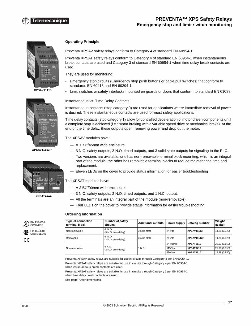
XPSAV and XPSAT Safety modules for emergency stop and switch monitoring
Operating Principle
Preventa XPSAV safety relays conform to Category 4 of standard EN 60954-1.
Preventa XPSAT safety relays conform to Category 4 of standard EN 60954-1 when instantaneous break contacts are used and Category 3 of standard EN 60954-1 when time delay break contacts are used.
They are used for monitoring:
• Emergency stop circuits (Emergency stop push buttons or cable pull switches) that conform to standards EN 60418 and EN 60204-1
• Limit switches or safety interlocks mounted on guards or doors that conform to standard EN 61088.
Instantaneous vs. Time Delay Contacts
Instantaneous contacts (stop category 0) are used for applications where immediate removal of power is desired. These instantaneous contacts are used for most safety applications.
Time delay contacts (stop category 1) allow for controlled deceleration of motor driven components until a complete stop is achieved (i.e.: motor braking with a variable speed drive or mechanical brake). At the end of the time delay, these outputs open, removing power and drop out the motor.
The XPSAV modules have:
— A 1.77"/45mm wide enclosure.
— 3 N.O. safety outputs, 3 N.O. timed outputs, and 3 solid state outputs for signaling to the PLC.
— Two versions are available: one has non-removable terminal block mounting, which is an integral part of the module, the other has removable terminal blocks to reduce maintenance time and replacement.
— Eleven LEDs on the cover to provide status information for easier troubleshooting
The XPSAT modules have:
— A 3.54"/90mm wide enclosure.
— 3 N.O. safety outputs, 2 N.O. timed outputs, and 1 N.C. output.
— All the terminals are an integral part of the module (non-removable).
— Four LEDs on the cover to provide status information for easier troubleshooting
Preventa XPSAV safety relays are suitable for use in circuits through Category 4 per EN 60954-1.
Preventa XPSAT safety relays are suitable for use in circuits through Category 4 per EN 60954-1 when instantaneous break contacts are used.
Preventa XPSAT safety relays are suitable for use in circuits through Category 3 per EN 60954-1 when time delay break contacts are used.
See page 70 for dimensions.
Ordering Information
Type of connection terminal block
Number of safety circuits
Additional outputs Power supply Catalog numberWeightoz (kg)
Non-removable6 N.O.(3 N.O. time delay)
3 solid state 24 Vdc XPSAV11113 11.29 (0.320)
Removable6 N.O.(3 N.O. time delay)
3 solid state 24 Vdc XPSAV11113P 11.29 (0.320)
Non-removable5 N.O.(2 N.O. time delay)
1 N.C.
24 Vac/dc XPSAT5110 22.93 (0.650)
115 Vac XPSAT3410 29.98 (0.850)
230 Vac XPSAT3710 29.98 (0.850)
17© 2003 Schneider Electric All Rights Reserved
PREVENTA™ XPS Safety RelaysEmergency stop and limit switch monitoring
18
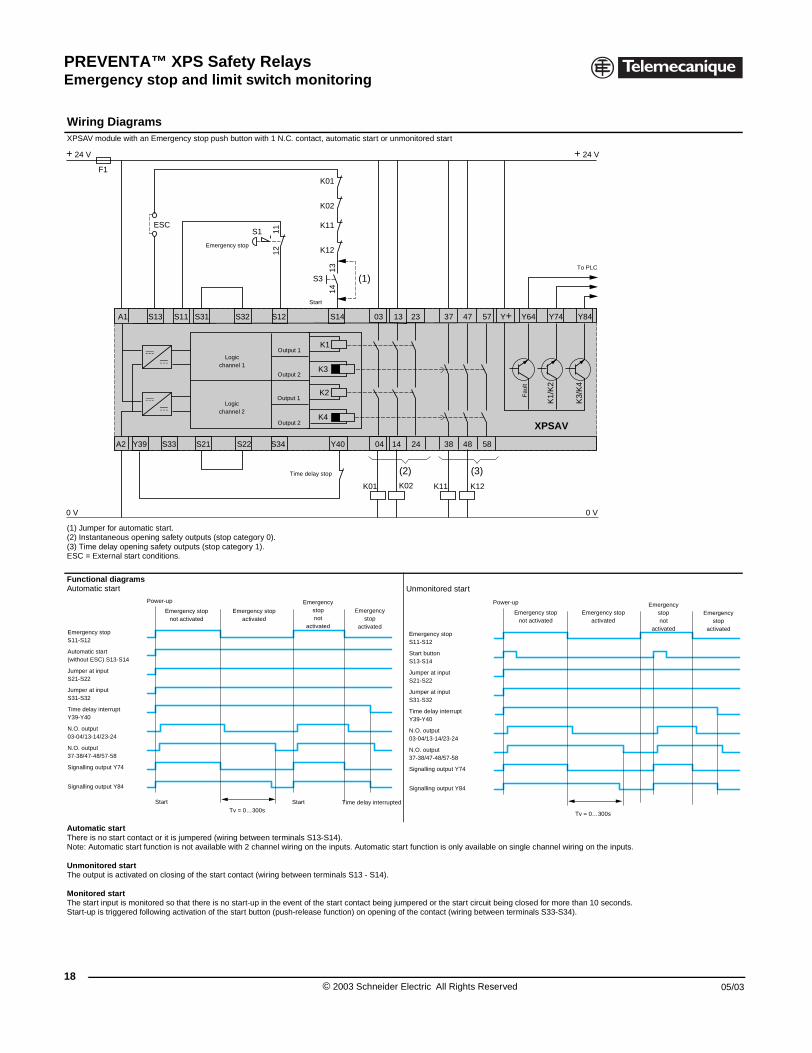
Wiring DiagramsXPSAV module with an Emergency
(1) Jumper for automatic start.(2) Instantaneous opening safety ou(3) Time delay opening safety outpuESC = External start conditions.
Functional diagramsAutomatic start
Automatic startThere is no start contact or it is jumpNote: Automatic start function is not
Unmonitored startThe output is activated on closing o
Monitored startThe start input is monitored so that Start-up is triggered following activa
F1
+ 24 V
0 V
A1
A2
S11S13
S33Y39
ESC
Emergency stop S11-S12
Automatic start(without ESC) S13-S14
Jumper at inputS21-S22
Jumper at inputS31-S32
Time delay interruptY39-Y40
N.O. output03-04/13-14/23-24
N.O. output37-38/47-48/57-58
Signalling output Y74
Signalling output Y84
Emergencnot activ
Power-up
Start
XPSAV and XPSAT Safety modules for emergency stop and switch monitoring
stop push button with 1 N.C. contact, automatic start or unmonitored start
tputs (stop category 0).ts (stop category 1).
Unmonitored start
ered (wiring between terminals S13-S14). available with 2 channel wiring on the inputs. Automatic start function is only available on single channel wiring on the inputs.
f the start contact (wiring between terminals S13 - S14).
there is no start-up in the event of the start contact being jumpered or the start circuit being closed for more than 10 seconds.tion of the start button (push-release function) on opening of the contact (wiring between terminals S33-S34).
+ 24 V
0 V
K2
K4
S1
13S31
XPSAV
S21 S22 04 14
03
1112
K02K01 K12
K3/
K4
K1/
K2
K11
S32 S14S12
S3
1314
K01
K02
K11
K12
Y40S34
K1
K3
37
38
47
48
23
24
57
58
Y64Y+ Y84Y74
(2)
(1)
(3)
To PLC
Fau
lt
Logicchannel 1
Logicchannel 2
Output 1
Output 2
Output 1
Output 2
Start
Time delay stop
Emergency stop
y stopated
Emergency stopactivated
Emergencystop not
activated
Emergencystop
activated
Start Time delay interruptedTv = 0…300s
Emergency stop S11-S12
Start button S13-S14
Jumper at inputS21-S22
Jumper at inputS31-S32
Time delay interruptY39-Y40
N.O. output03-04/13-14/23-24
N.O. output37-38/47-48/57-58
Signalling output Y74
Signalling output Y84
Emergency stopnot activated
Power-up
Emergency stopactivated
Emergencystop
activated
Emergencystopnot
activated
Tv = 0…300s
© 2003 Schneider Electric All Rights Reserved 05/03
PREVENTA™ XPS Safety RelaysEmergency stop and limit switch monitoring
05/03
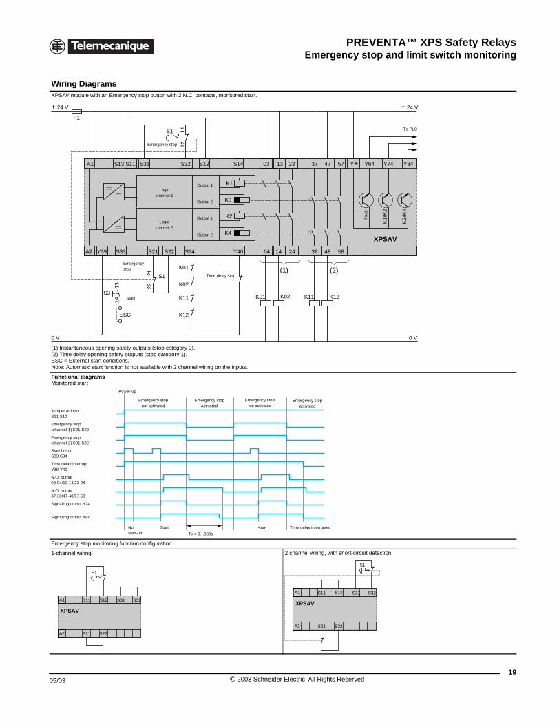
Wiring DiagramsXPSAV module with an Emergency
(1) Instantaneous opening safety ou(2) Time delay opening safety outpuESC = External start conditions.Note: Automatic start function is not
Functional diagramsMonitored start
Emergency stop monitoring function
1-channel wiring
F1
+ 24 V
0 V
A1
A2
S11S13
S33Y39
S3
1314
ESC
Start
Emergestop
Jumper at inputS11-S12
Emergency stop(channel 1) S21-S22
Emergency stop(channel 2) S31-S32
Start buttonS33-S34
Time delay interruptY39-Y40
N.O. output03-04/13-14/23-24
N.O. output37-38/47-48/57-58
Signalling output Y74
Signalling output Y84
Power-up
Nostart-
XPSAV
S1
A1 S11 S31 S3
A2 S21 S22
S12
XPSAV and XPSAT Safety modules for emergency stop and switch monitoring
stop button with 2 N.C. contacts, monitored start.
tputs (stop category 0).ts (stop category 1).
available with 2 channel wiring on the inputs.
configuration
2 channel wiring, with short-circuit detection
+ 24 V
0 V
K2
K4
S1
13S31
XPSAV
S21 S22 04 14
03
K01
K02
K11
2122
1112
K12
K02K01 K12
K3/
K4
K1/
K2
K11
S32 S14S12
Y40S34
S1
K1
K3
37
38
47
48
23
24
57
58
Y64Y+ Y84Y74
(1) (2)
To PLC
Logicchannel 1
Logicchannel 2
Output 1
Output 2
Output 1
Output 2
Time delay stop
Emergency stop
Fau
lt
ncy
Emergency stopnot activated
Emergency stopactivated
Emergency stopnot activated
Emergency stopactivated
upStart Time delay interruptedStart
Tv = 0…300s
2XPSAV
S1
A1 S11 S31 S32
A2 S21 S22
S12
19© 2003 Schneider Electric All Rights Reserved
PREVENTA™ XPS Safety RelaysEmergency stop and limit switch monitoring
20
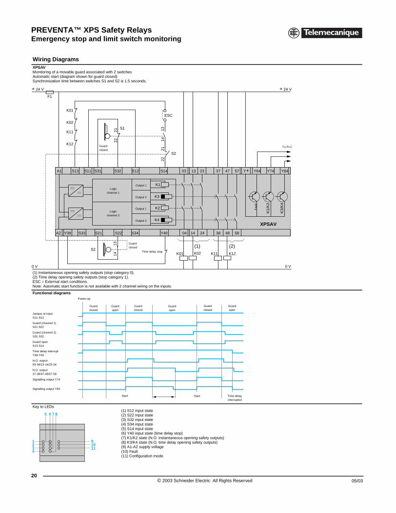
Wiring DiagramsXPSAVMonitoring of a movable guard assoAutomatic start (diagram shown for Synchronization time between switc
(1) Instantaneous opening safety ou(2) Time delay opening safety outpuESC = External start conditions.Note: Automatic start function is not
Functional diagrams
Key to LEDs
F1
+ 24 V
0 V
S2
A1
A2
S11S13
S33Y39
K01
K02
K11
K12
Power-up
Jumper at inputS11-S12
Guard (channel 1)S21-S22
Guard (channel 2)S31-S32
Guard openS13-S14
Time delay interruptY39-Y40
N.O. output03-04/13-14/23-24
N.O. output37-38/47-48/57-58
Signalling output Y74
Signalling output Y84
Guaclos
1
5 6 7 8
234
91011
XPSAV and XPSAT Safety modules for emergency stop and switch monitoring
ciated with 2 switchesguard closed)hes S1 and S2 is 1.5 seconds.
tputs (stop category 0).ts (stop category 1).
available with 2 channel wiring on the inputs.
(1) S12 input state(2) S22 input state(3) S32 input state(4) S34 input state(5) S14 input state(6) Y40 input state (time delay stop)(7) K1/K2 state (N.O. instantaneous opening safety outputs)(8) K3/K4 state (N.O. time delay opening safety outputs)(9) A1-A2 supply voltage(10) Fault(11) Configuration mode
+ 24 V
0 V
K2
K4
S1
13S31
XPSAV
S21 S22 04 14
03
2122
1314
2122
K02K01 K12
K3/
K4
K1/
K2
K11
S32 S14S12
1314
ESC
S2
Y40S34
K1
K3
37
38
47
48
23
24
57
58
Y64Y+ Y84Y74
(1) (2)Time delay stop
Fau
lt
Guardclosed
Guardclosed
To PLC
Logicchannel 1
Logicchannel 2
Output 1
Output 2
Output 1
Output 2
rded
Guardopen
Guardclosed
Guardopen
Guardclosed
Guardopen
Start Time delayinterrupted
Start
© 2003 Schneider Electric All Rights Reserved 05/03
PREVENTA™ XPS Safety RelaysEmergency stop and limit switch monitoring
05/03
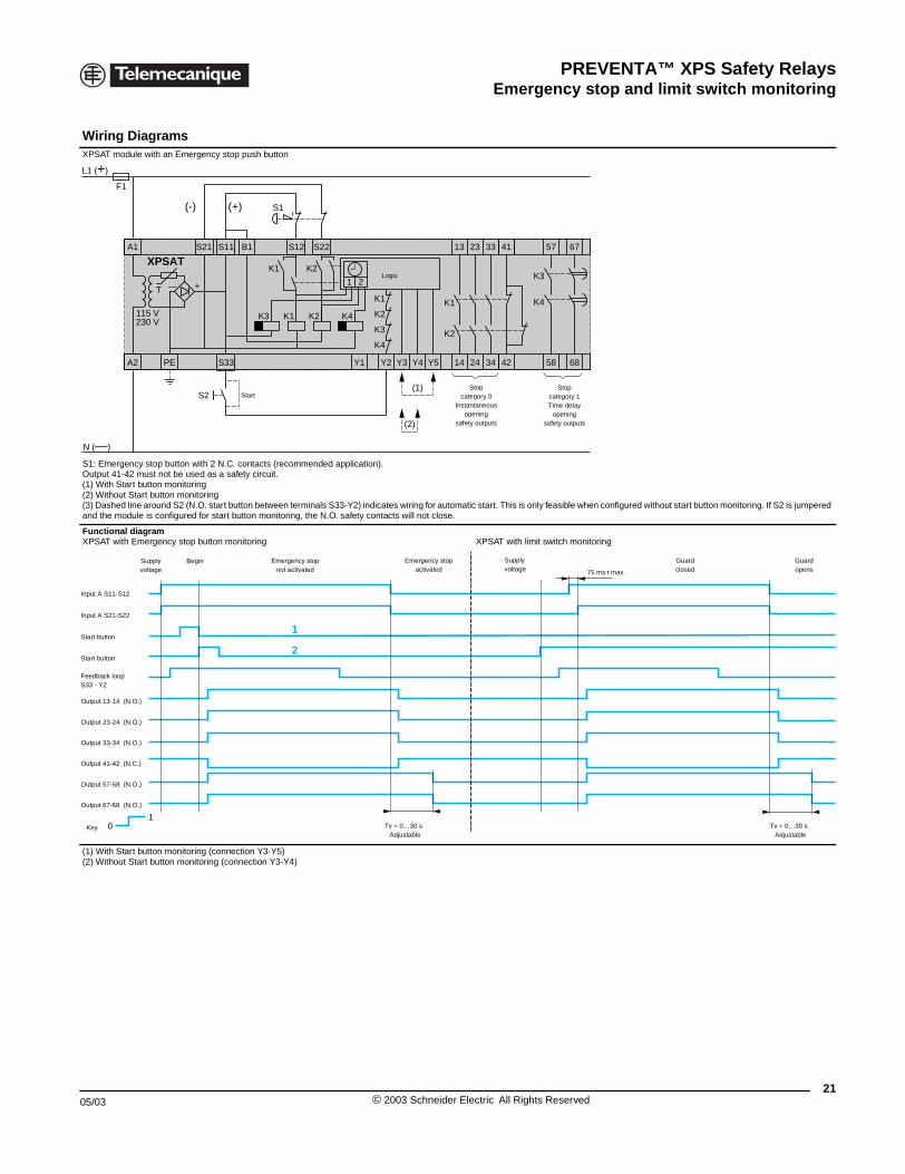
Wiring DiagramsXPSAT module with an Emergency
S1: Emergency stop button with 2 NOutput 41-42 must not be used as a(1) With Start button monitoring(2) Without Start button monitoring(3) Dashed line around S2 (N.O. starand the module is configured for sta
Functional diagramXPSAT with Emergency stop button
(1) With Start button monitoring (con(2) Without Start button monitoring (
S21 SA1
A2 PE
L1 (+)
N (—)
T — +
115 V230 V
S
XPSAT
S2
F1
(-)
01
Supplyvoltage
Begin
Input A S11-S12
Input A S21-S22
Start button
Start button
Feedback loopS33 - Y2
Output 13-14 (N.O.)
Output 23-24 (N.O.)
Output 33-34 (N.O.)
Output 41-42 (N.C.)
Output 57-58 (N.O.)
Output 67-68 (N.O.)
Key
XPSAV and XPSAT Safety modules for emergency stop and switch monitoring
stop push button
.C. contacts (recommended application). safety circuit.
t button between terminals S33-Y2) indicates wiring for automatic start. This is only feasible when configured without start button monitoring. If S2 is jumpered rt button monitoring, the N.O. safety contacts will not close.
monitoring XPSAT with limit switch monitoring
nection Y3-Y5)connection Y3-Y4)
11
Y1
13
2
K2
K1
K3
K4
K1 K2K3
23
2414 34 42 6858
33 41 57 67B1 S12 S22
33 Y2 Y3
K4
K1 K2
K2
K1
1
Y4 Y5
K3
K4
S1
(1)
(2)
(+)
Start
Logic
Stopcategory 0
Instantaneousopening
safety outputs
Stopcategory 1Time delay
openingsafety outputs
2
1
Tv = 0…30 sAdjustable
75 ms t max.
Supplyvoltage
Emergency stopactivated
Emergency stopnot activated
Guardclosed
Guardopens
Tv = 0…30 sAdjustable
21© 2003 Schneider Electric All Rights Reserved
PREVENTA™ XPS Safety RelaysEmergency stop and limit switch monitoring
22
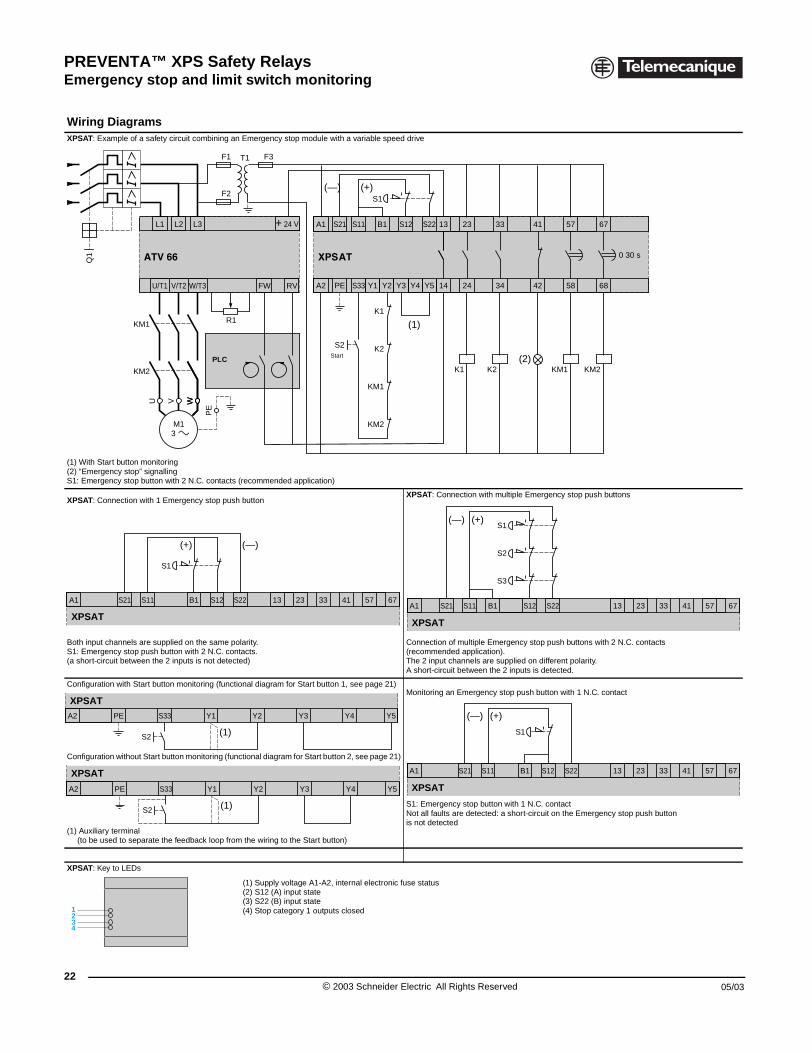
Wiring DiagramsXPSAT: Example of a safety circuit
(1) With Start button monitoring(2) “Emergency stop” signallingS1: Emergency stop button with 2 N
XPSAT: Connection with 1 Emergen
Both input channels are supplied onS1: Emergency stop push button wi(a short-circuit between the 2 inputs
Configuration with Start button mon
Configuration without Start button m
(1) Auxiliary terminal (to be used to separate the feedb
XPSAT: Key to LEDs
Q1
KM2
U
KM1
V
M13
L2
U/T1 V/T2 W
L1
S11S21A1 B
S1
XPSAT
(+)
S2
A2 PE S33
XPSAT
A2 PE S33
XPSAT
S2
1234
XPSAV and XPSAT Safety modules for emergency stop and switch monitoring
combining an Emergency stop module with a variable speed drive
.C. contacts (recommended application)
cy stop push buttonXPSAT: Connection with multiple Emergency stop push buttons
the same polarity.th 2 N.C. contacts. is not detected)
Connection of multiple Emergency stop push buttons with 2 N.C. contacts (recommended application).The 2 input channels are supplied on different polarity. A short-circuit between the 2 inputs is detected.
itoring (functional diagram for Start button 1, see page 21)
onitoring (functional diagram for Start button 2, see page 21)
ack loop from the wiring to the Start button)
Monitoring an Emergency stop push button with 1 N.C. contact
S1: Emergency stop button with 1 N.C. contactNot all faults are detected: a short-circuit on the Emergency stop push buttonis not detected
(1) Supply voltage A1-A2, internal electronic fuse status(2) S12 (A) input state(3) S22 (B) input state(4) Stop category 1 outputs closed
K1
S2
S1
S11S21A1 13 57 67
A2 PE S33 Y1 Y2 Y3 Y4 Y5 14 24 34 42 6858
S22B1 S12 23 33 41
F3
K2
KM1
KM2
KM2KM1 K2K1
WW
F1
+ 24 VL3
/T3
R1
PE
T1
FW RV
0 30 s
F2
(1)
(—) (+)
(2)StartPLC
13 57 67S221 S12 23 33 41
(—)
S3
S11S21A1 13 57 67S22B1 S12 23 33 41
S2
S1
XPSAT
(+)(—)
Y1 Y2 Y3 Y4 Y5
(1)
Y1 Y2 Y3 Y4 Y5
(1)
S11S21A1 13 57 67S22B1 S12 23 33 41
S1
XPSAT
(+)(—)
© 2003 Schneider Electric All Rights Reserved 05/03
PREVENTA™ XPS Safety RelaysEmergency stop and limit switch monitoring
05/03
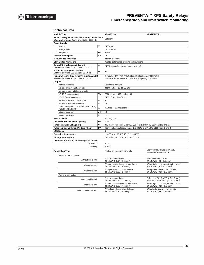
XPSAF Emergency stop and limit switch monitoring
Technical DataModule Type XPSAF5130 XPSAF5130P
Product designed for max. use in safety related parts of control systems (conforming to EN 60954-1)
Category 4
Power Supply
Voltage V 24 Vac/dc
Voltage limits - 15 to +10%
Frequency Hz 50/60
Power Consumption VA ≤ 5
Module Fuse Protection Internal electronic
Start Button Monitoring Yes/No (determined by wring configuration)
Control Unit Voltage and CurrentBetween terminals S11-S12 and S21-S22
V 24 Vdc/30mA (at nominal supply voltage)
Maximum Wiring Resistance RLBetween terminals S11-S12 and S21-S22
Ω 90
Synchronization Time Between Inputs A and B Between terminals S11-S12 and S21-S22
Automatic Start (terminals S33 and S39 jumpered): UnlimitedManual Start (terminals S33 and S34 jumpered): Unlimited
Outputs
Voltage reference Relay hard contacts
No. and type of safety circuits 3 N.O. (13-14, 23-24, 33-34)
No. and type of additional circuits –
AC-15 Breaking capacity VA C300: inrush 1800, sealed 180
DC-13 Breaking capacity 24 V/1.5 A - L/R = 50 ms
Maximum thermal current (Ithe) A 6
Maximum total thermal current A 18
Output fuse protection per IEC 60947-5-1, VDE 0660 Part 200
A 4 A fuse or 6 A fast acting
Minimum current mA 10
Minimum voltage V 17
Electrical Life See page 11.
Response Time on Input Opening ms < 20
Rated Insulation Voltage (Ui) V 300 (Pollution degree 2 per IEC 60947-5-1, DIN VDE 0110 Parts 1 and 2)
Rated Impulse Withstand Voltage (Uimp) kV 4 (Overvoltage category III, per IEC 60947-1, DIN VDE 0110 Parts 1 and 2)
LED Display 3
Operating Temperature + 14 °F to + 130 °F (- 10 °C to + 55 °C)
Storage Temperature - 13 °F to + 185 °F (- 25 °C to + 85 °C)
Degree of Protection conforming to IEC 60529
Terminals IP 20
Housing IP 40
Connection Type Captive screw-clamp terminalsCaptive screw-clamp terminals, removable terminal block
Single Wire Connection
Without cable endSolid or stranded wire:26-14 AWG (0.14 - 2.5 mm2)
Solid or stranded wire:24-14 AWG (0.2 - 2.5 mm2)
With cable endWithout plastic sleeve, stranded wire:24-14 AWG (0.25 - 2.5 mm2)
Without plastic sleeve, stranded wire:24-14 AWG (0.25 - 2.5 mm2)
With cable endWith plastic sleeve, stranded wire:24-16 AWG (0.25 - 1.5 mm2)
With plastic sleeve, stranded wire:24-14 AWG (0.25 - 2.5 mm2)
Two wire connection
Without cable endSolid or stranded wire:26-20 AWG (0.14 - 0.75 mm2)
Solid wire: 24-18 AWG (0.2 -1.0 mm2)Stranded: 24-16 AWG (0.2 - 1.5 mm2)
With cable endWithout plastic sleeve, stranded wire:24-20 AWG (0.25 - 7.5 mm2)
Without plastic sleeve, stranded wire:24-18 AWG (0.25 - 1.0 mm2)
With double cable endWith plastic sleeve, stranded wire:22-14 AWG (0.5 - 1.5 mm2)
With plastic sleeve, stranded wire:22-14 AWG (0.5 - 1.5 mm2)
23© 2003 Schneider Electric All Rights Reserved
PREVENTA™ XPS Safety RelaysEmergency stop and limit switch monitoring
24
®
File E164353CCN NKCR
File LR44087Class 3211 03
XPSAF5130P
XPSAF5130
APSAF Series B
Operating Principle
Preventa XPSAF safety relays conform to Category 4 of standard EN 60954-1. They are used for monitoring:
• Emergency stop circuits (Emergency stop push buttons or cable pull switches) that conform to standards EN 60418 and EN 60204-1
• Limit switches or safety interlocks mounted on guards or doors that conform to standard EN 61088.
These modules have a compact enclosure (0.89"/22.5mm wide)
Three N.O. safety outputs
Start button monitoring can be configured by wiring
Two versions are available: one has non-removable terminal block mounting, which is an integral part of the module, the other has removable terminal blocks to reduce maintenance time and replacement.
Three LEDs on the cover to provide status information for easier troubleshooting
Suitable for use in circuits through Category 4 per EN 60954-1.
See page 70 for dimensions.
Ordering Information
DescriptionType of Terminal Block
No. of SafetyCircuits
Power Supply Catalog NumberWeight oz. (kg)
Safety Modules for emergency stop and limit switch monitoring
Non-removable 3 24 Vac/dc XPSAF5130 9 (0.250)
Removable 3 24 Vac/dc XPSAF5130P 9 (0.250)
© 2003 Schneider Electric All Rights Reserved 05/03
PREVENTA™ XPS Safety RelaysEmergency stop and limit switch monitoring
05/03
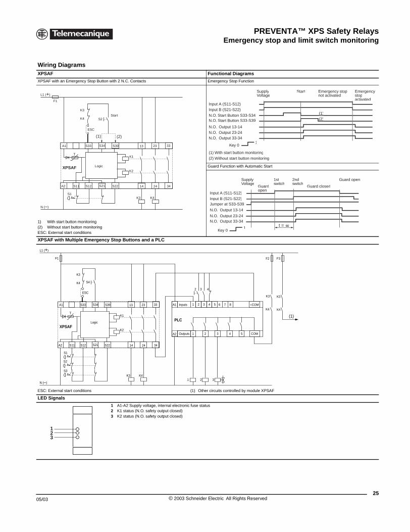
Wiring DiagramsXPSAF
XPSAF with an Emergency Stop Bu
1) With start button monitoring(2) Without start button monitoringESC: External start conditions
XPSAF with Multiple Emerge
ESC: External start conditions
LED Signals
F1
L1 (+)
N (–)
T
S1
A1
A2
SS33
XPSAF
SS12S11
S2
K3
K4
ESC
(1)
Logi
F1
L1 (+)
N (–)
T
A1
A2
S34S33
LogicXPSAF
S21S12S11
S4
K3
K4
ESC
S1
S2
S3
123
APSAF Series B
Functional Diagrams
tton with 2 N.C. Contacts Emergency Stop Function
Guard Function with Automatic Start
ncy Stop Buttons and a PLC
(1) Other circuits controlled by module XPSAF
1 A1-A2 Supply voltage, internal electronic fuse status2 K1 status (N.O. safety output closed)3 K2 status (N.O. safety output closed)
K1
K2
3334 S39
S2221 14 24 34
2313
K4K3
(2)
c
Start (1)( )(2)( )
SupplyVoltage
Start Emergencystopactivated
Emergency stopnot activated
Input A (S11-S12)
N.O. Start Button S33-S34Input B (S21-S22)
N.O. Start Button S33-S39
N.O. Output 23-24N.O. Output 33-34
N.O. Output 13-14
1Key 0
(1) With start button monitoring(2) Without start button monitoring
SupplyVoltage
Guardopen
Guard closed
1stswitch
2ndswitch
Guard open
Input A (S11-S12)
Jumper at S33-S39Input B (S21-S22)
N.O. Output 23-24N.O. Output 33-34
N.O. Output 13-14
1Key 0
8t =
K1
K2
33S39
PLC
S22 14 24 34
2313
K4K32 31
1 43 5 +COM
COM321
2
F3
K3
K4
3 42
(1)
F2
A1 Inputs
OutputsA2
76 8
4 5
K3
K4
25© 2003 Schneider Electric All Rights Reserved
PREVENTA™ XPS Safety RelaysEmergency stop and limit switch monitoring
26
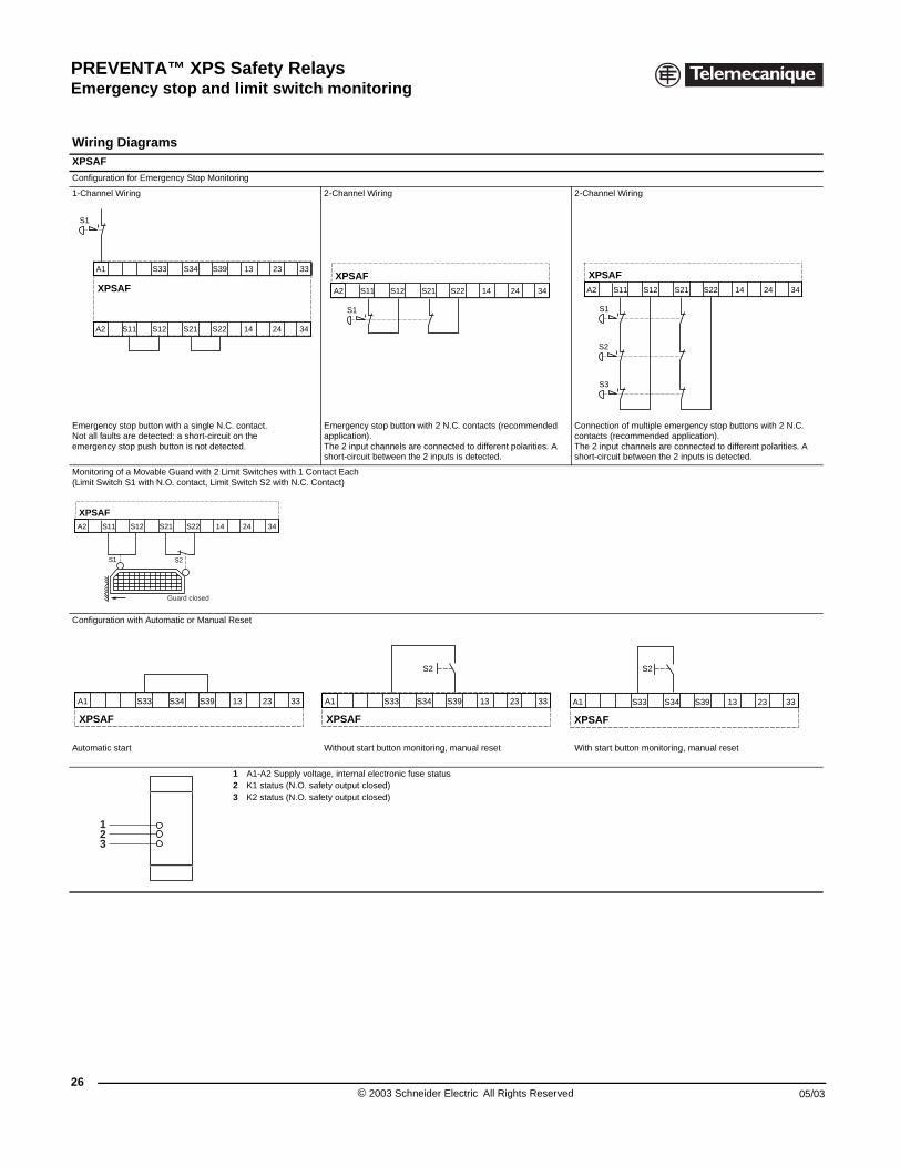
Wiring DiagramsXPSAF
Configuration for Emergency Stop M
1-Channel Wiring
Emergency stop button with a singleNot all faults are detected: a short-ciemergency stop push button is not d
Monitoring of a Movable Guard with (Limit Switch S1 with N.O. contact, L
Configuration with Automatic or Man
Automatic start
XPSAF
S1
A1 S33 S34
A2 S11 S12 S21
S1 S2
XPSAFA2 S11 S12 S21 S22
Guard closed
XPSAF
A1 S33 S34 S39
123
APSAF Series B
onitoring
2-Channel Wiring 2-Channel Wiring
N.C. contact.rcuit on the etected.
Emergency stop button with 2 N.C. contacts (recommended application).The 2 input channels are connected to different polarities. A short-circuit between the 2 inputs is detected.
Connection of multiple emergency stop buttons with 2 N.C. contacts (recommended application).The 2 input channels are connected to different polarities. A short-circuit between the 2 inputs is detected.
2 Limit Switches with 1 Contact Each imit Switch S2 with N.C. Contact)
ual Reset
Without start button monitoring, manual reset With start button monitoring, manual reset
1 A1-A2 Supply voltage, internal electronic fuse status2 K1 status (N.O. safety output closed)3 K2 status (N.O. safety output closed)
S39 13 23 33
S22 14 24 34
XPSAF
S1
A2 S11 S12 S21 S22 14 24 34
S1
S2
S3
XPSAFA2 S11 S12 S21 S22 14 24 34
14 24 34
13 23 33
XPSAF
S2
A1 S33 S34 S39 13 23 33
XPSAF
S2
A1 S33 S34 S39 13 23 33
© 2003 Schneider Electric All Rights Reserved 05/03
PREVENTA™ XPS Safety RelaysEmergency stop, limit switch and light curtain monitoring
05/03
XPSAFL Safety modules for monitoring emergency stops, switches and light cur tains
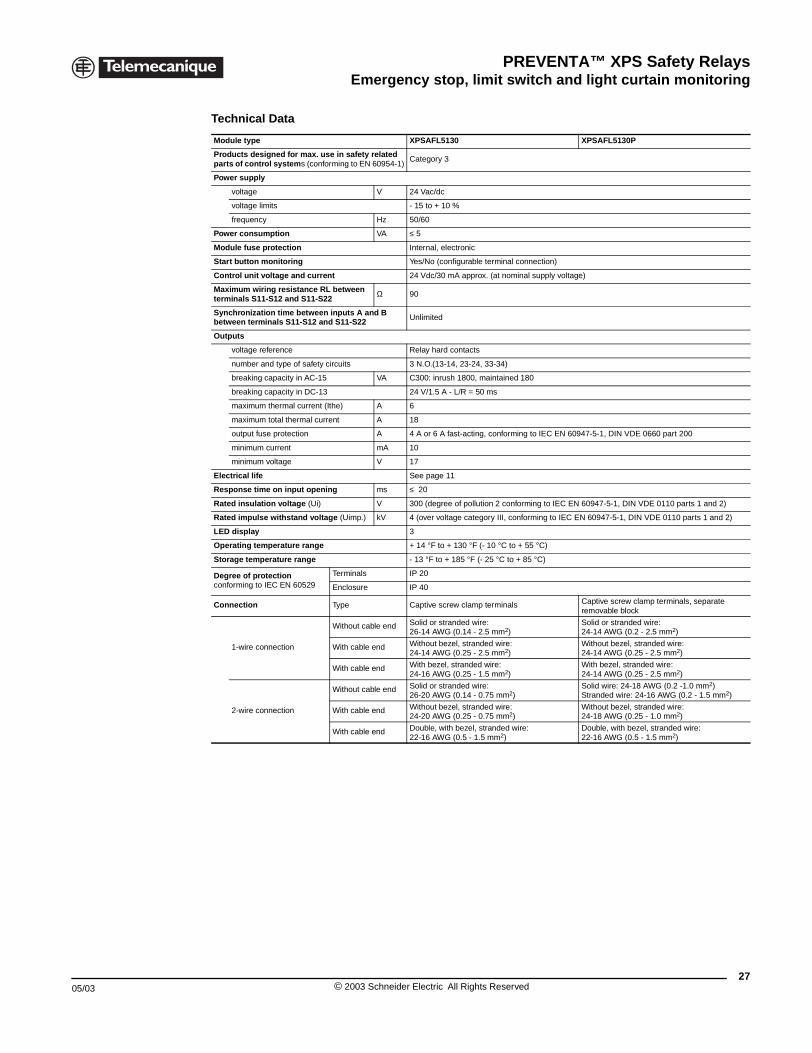
Technical Data
Module type XPSAFL5130 XPSAFL5130P
Products designed for max. use in safety related parts of control systems (conforming to EN 60954-1)
Category 3
Power supply
voltage V 24 Vac/dc
voltage limits - 15 to + 10 %
frequency Hz 50/60
Power consumption VA ≤ 5
Module fuse protection Internal, electronic
Start button monitoring Yes/No (configurable terminal connection)
Control unit voltage and current 24 Vdc/30 mA approx. (at nominal supply voltage)
Maximum wiring resistance RL between terminals S11-S12 and S11-S22
Ω 90
Synchronization time between inputs A and B between terminals S11-S12 and S11-S22 Unlimited
Outputs
voltage reference Relay hard contacts
number and type of safety circuits 3 N.O.(13-14, 23-24, 33-34)
breaking capacity in AC-15 VA C300: inrush 1800, maintained 180
breaking capacity in DC-13 24 V/1.5 A - L/R = 50 ms
maximum thermal current (Ithe) A 6
maximum total thermal current A 18
output fuse protection A 4 A or 6 A fast-acting, conforming to IEC EN 60947-5-1, DIN VDE 0660 part 200
minimum current mA 10
minimum voltage V 17
Electrical life See page 11
Response time on input opening ms ≤ 20
Rated insulation voltage (Ui) V 300 (degree of pollution 2 conforming to IEC EN 60947-5-1, DIN VDE 0110 parts 1 and 2)
Rated impulse withstand voltage (Uimp.) kV 4 (over voltage category III, conforming to IEC EN 60947-5-1, DIN VDE 0110 parts 1 and 2)
LED display 3
Operating temperature range + 14 °F to + 130 °F (- 10 °C to + 55 °C)
Storage temperature range - 13 °F to + 185 °F (- 25 °C to + 85 °C)
Degree of protectionconforming to IEC EN 60529
Terminals IP 20
Enclosure IP 40
Connection Type Captive screw clamp terminals Captive screw clamp terminals, separate removable block
1-wire connection
Without cable end Solid or stranded wire: 26-14 AWG (0.14 - 2.5 mm2)
Solid or stranded wire: 24-14 AWG (0.2 - 2.5 mm2)
With cable end Without bezel, stranded wire:24-14 AWG (0.25 - 2.5 mm2)
Without bezel, stranded wire:24-14 AWG (0.25 - 2.5 mm2)
With cable end With bezel, stranded wire: 24-16 AWG (0.25 - 1.5 mm2)
With bezel, stranded wire: 24-14 AWG (0.25 - 2.5 mm2)
2-wire connection
Without cable end Solid or stranded wire: 26-20 AWG (0.14 - 0.75 mm2)
Solid wire: 24-18 AWG (0.2 -1.0 mm2)Stranded wire: 24-16 AWG (0.2 - 1.5 mm2)
With cable end Without bezel, stranded wire: 24-20 AWG (0.25 - 0.75 mm2)
Without bezel, stranded wire: 24-18 AWG (0.25 - 1.0 mm2)
With cable end Double, with bezel, stranded wire: 22-16 AWG (0.5 - 1.5 mm2)
Double, with bezel, stranded wire: 22-16 AWG (0.5 - 1.5 mm2)
27© 2003 Schneider Electric All Rights Reserved
PREVENTA™ XPS Safety RelaysEmergency stop, limit switch and light curtain monitoring
28
®
File E164353CCN NKCR
File LR44087Class 3211 03
XPSAFL5130
XPSAFL5130P
XPSAFL Safety modules for monitoring emergency stops, switches and light curtains
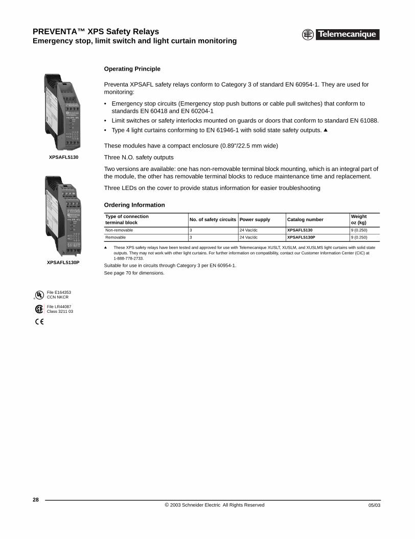
Operating Principle
Preventa XPSAFL safety relays conform to Category 3 of standard EN 60954-1. They are used for monitoring:
• Emergency stop circuits (Emergency stop push buttons or cable pull switches) that conform to standards EN 60418 and EN 60204-1
• Limit switches or safety interlocks mounted on guards or doors that conform to standard EN 61088.
• Type 4 light curtains conforming to EN 61946-1 with solid state safety outputs. q
These modules have a compact enclosure (0.89"/22.5 mm wide)
Three N.O. safety outputs
Two versions are available: one has non-removable terminal block mounting, which is an integral part of the module, the other has removable terminal blocks to reduce maintenance time and replacement.
Three LEDs on the cover to provide status information for easier troubleshooting
q These XPS safety relays have been tested and approved for use with Telemecanique XUSLT, XUSLM, and XUSLMS light curtains with solid state outputs. They may not work with other light curtains. For further information on compatibility, contact our Customer Information Center (CIC) at 1-888-778-2733.
Suitable for use in circuits through Category 3 per EN 60954-1.
See page 70 for dimensions.
Ordering Information
Type of connection terminal block
No. of safety circuits Power supply Catalog numberWeight oz (kg)
Non-removable 3 24 Vac/dc XPSAFL5130 9 (0.250)
Removable 3 24 Vac/dc XPSAFL5130P 9 (0.250)
© 2003 Schneider Electric All Rights Reserved 05/03
PREVENTA™ XPS Safety RelaysEmergency stop, limit switch and light curtain monitoring
05/03
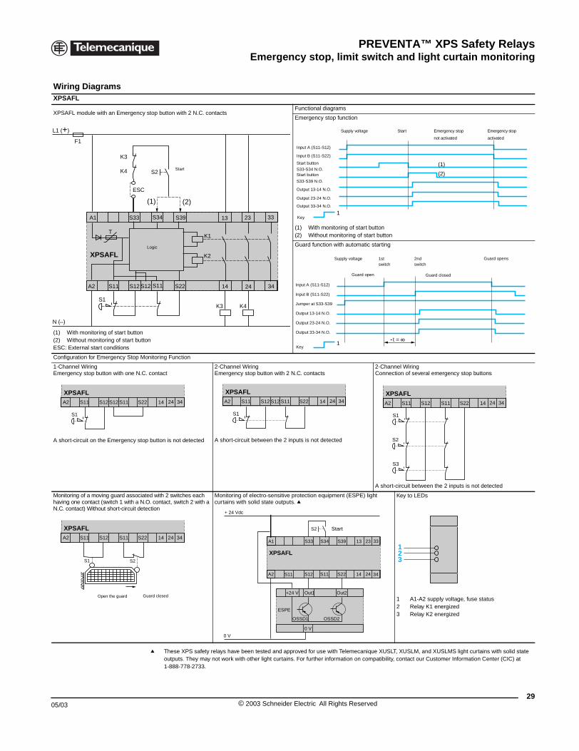
Wiring DiagramsXPSAFL
XPSAFL module with an Emergenc
(1) With monitoring of start button(2) Without monitoring of start butESC: External start conditions
Configuration for Emergency Stop M
1-Channel WiringEmergency stop button with one N.C
A short-circuit on the Emergency sto
Monitoring of a moving guard associahaving one contact (switch 1 with a NN.C. contact) Without short-circuit de
F1
L1 (+)
N ( )
T
S1
A1
A2
S33
XPSAFL
S12S11
K3
K4
ESC
S
XPSAFL
S1
A2 S11 S12 S11 S2S12
S1 S2
XPSAFLA2 S11 S12 S11 S2
Open the guard
XPSAFL Safety modules for monitoring emergency stops, switches and light cur tains
q These XPS safety relays have been tested and approved for use with Telemecanique XUSLT, XUSLM, and XUSLMS light curtains with solid state outputs. They may not work with other light curtains. For further information on compatibility, contact our Customer Information Center (CIC) at 1-888-778-2733.
y stop button with 2 N.C. contactsFunctional diagrams
Emergency stop function
ton
(1) With monitoring of start button(2) Without monitoring of start button
Guard function with automatic starting
onitoring Function
. contact2-Channel WiringEmergency stop button with 2 N.C. contacts
2-Channel WiringConnection of several emergency stop buttons
p button is not detected A short-circuit between the 2 inputs is not detected
A short-circuit between the 2 inputs is not detected
ted with 2 switches each .O. contact, switch 2 with a tection
Monitoring of electro-sensitive protection equipment (ESPE) light curtains with solid state outputs. q
Key to LEDs
1 A1-A2 supply voltage, fuse status2 Relay K1 energized3 Relay K2 energized
K1
K2
33S34 S39
S22S11 14 24 34
2313
S2
K4K3
(1) (2)
12
Start
Logic
1
(1)
(2)
Supply voltage Start Emergency stop
not activated
Emergency stop
activated
Input A (S11-S12)
Input B (S11-S22)
Start button
S33-S34 N.O.Start button
S33-S39 N.O.
Output 13-14 N.O.
Output 23-24 N.O.
Output 33-34 N.O.
Key
1t =
Supply voltage 1st
switch2ndswitch
Guard open Guard closed
Guard opens
Input A (S11-S12)
Input B (S11-S22)
Jumper at S33-S39
Output 13-14 N.O.
Output 23-24 N.O.
Output 33-34 N.O.
Key
2 14 24 34
XPSAFL
S1
A2 S11 S12 S11 S22 14 24 34S12
S1
S2
S3
XPSAFLA2 S11 S12 S11 S22 14 24 34
XPSAFL
A1 S33 S34 S39 13 23 33
A2 S11 S12 S11 S22 14 24 34
+ 24 Vdc
+24 V Out1
OSSD1
ESPE
OSSD2
Out2
0 V
0 V
S2 Start
123
2 14 24 34
Guard closed
29© 2003 Schneider Electric All Rights Reserved
PREVENTA™ XPS Safety RelaysEmergency stop, limit switch and light curtain monitoring
30
XPSAR Safety modules for emergency stop, switch and light curtain monitoring
Technical Data
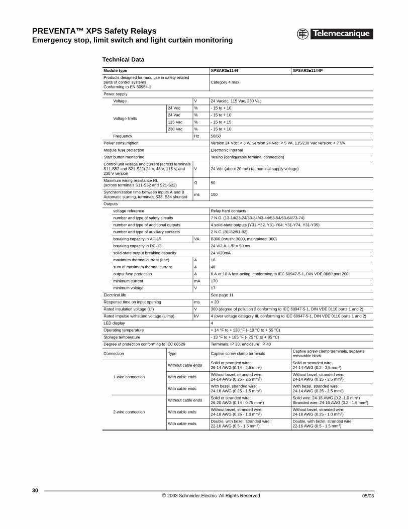
Module type XPSAR3p1144 XPSAR3p1144P
Products designed for max. use in safety related parts of control systemsConforming to EN 60954-1
Category 4 max.
Power supply
Voltage V 24 Vac/dc, 115 Vac, 230 Vac
Voltage limits
24 Vdc % - 15 to + 10
24 Vac % - 15 to + 10
115 Vac % - 15 to + 15
230 Vac % - 15 to + 10
Frequency Hz 50/60
Power consumption Version 24 Vdc: < 3 W, version 24 Vac: < 5 VA, 115/230 Vac version: < 7 VA
Module fuse protection Electronic internal
Start button monitoring Yes/no (configurable terminal connection)
Control unit voltage and current (across terminals S11-S52 and S21-S22) 24 V, 48 V, 115 V, and 230 V version
V 24 Vdc (about 20 mA) (at nominal supply voltage)
Maximum wiring resistance RL(across terminals S11-S52 and S21-S22)
Ω 50
Synchronization time between inputs A and BAutomatic starting, terminals S33, S34 shunted
ms 100
Outputs
voltage reference Relay hard contacts
number and type of safety circuits 7 N.O. (13-14/23-24/33-34/43-44/53-54/63-64/73-74)
number and type of additional outputs 4 solid-state outputs (Y31-Y32, Y31-Y64, Y31-Y74, Y31-Y35)
number and type of auxiliary contacts 2 N.C. (81-82/91-92)
breaking capacity in AC-15 VA B300 (inrush: 3600, maintained: 360)
breaking capacity in DC-13 24 V/2 A, L/R = 50 ms
solid-state output breaking capacity 24 V/20mA
maximum thermal current (Ithe) A 10
sum of maximum thermal current A 40
output fuse protection A 6 A or 10 A fast-acting, conforming to IEC 60947-5-1, DIN VDE 0660 part 200
minimum current mA 170
minimum voltage V 17
Electrical life See page 11
Response time on input opening ms < 20
Rated insulation voltage (Ui) V 300 (degree of pollution 2 conforming to IEC 60947-5-1, DIN VDE 0110 parts 1 and 2)
Rated impulse withstand voltage (Uimp) kV 4 (over voltage category III, conforming to IEC 60947-5-1, DIN VDE 0110 parts 1 and 2)
LED display 4
Operating temperature + 14 °F to + 130 °F (- 10 °C to + 55 °C)
Storage temperature - 13 °F to + 185 °F (- 25 °C to + 85 °C)
Degree of protection conforming to IEC 60529 Terminals: IP 20, enclosure: IP 40
Connection Type Captive screw clamp terminalsCaptive screw clamp terminals, separate removable block
1-wire connection
Without cable endsSolid or stranded wire: 26-14 AWG (0.14 - 2.5 mm2)
Solid or stranded wire: 24-14 AWG (0.2 - 2.5 mm2)
With cable endsWithout bezel, stranded wire: 24-14 AWG (0.25 - 2.5 mm2)
Without bezel, stranded wire: 24-14 AWG (0.25 - 2.5 mm2)
With cable endsWith bezel, stranded wire: 24-16 AWG (0.25 - 1.5 mm2)
With bezel, stranded wire: 24-14 AWG (0.25 - 2.5 mm2)
2-wire connection
Without cable endsSolid or stranded wire:26-20 AWG (0.14 - 0.75 mm2)
Solid wire: 24-18 AWG (0.2 -1.0 mm2)Stranded wire: 24-16 AWG (0.2 - 1.5 mm2)
With cable endsWithout bezel, stranded wire: 24-18 AWG (0.25 - 1.0 mm2)
Without bezel, stranded wire: 24-18 AWG (0.25 - 1.0 mm2)
With cable endsDouble, with bezel, stranded wire: 22-16 AWG (0.5 - 1.5 mm2)
Double, with bezel, stranded wire: 22-16 AWG (0.5 - 1.5 mm2)
© 2003 Schneider Electric All Rights Reserved 05/03
PREVENTA™ XPS Safety RelaysEmergency stop, limit switch and light curtain monitoring
05/03
®
File E164353CCN NKCR
File LR44087Class 3211 03
XPSAR3p1144
XPSAR Safety modules for emergency stop, switch and light curtain monitoring
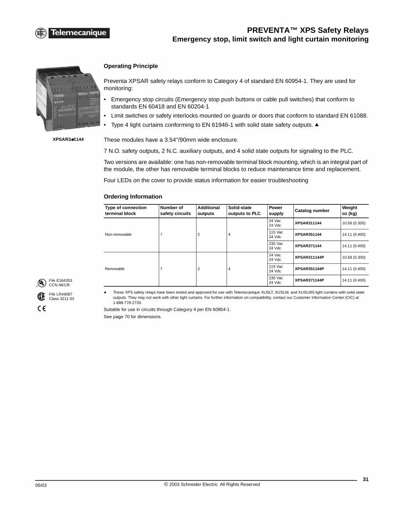
Operating Principle
Preventa XPSAR safety relays conform to Category 4 of standard EN 60954-1. They are used for monitoring:
• Emergency stop circuits (Emergency stop push buttons or cable pull switches) that conform to standards EN 60418 and EN 60204-1
• Limit switches or safety interlocks mounted on guards or doors that conform to standard EN 61088.
• Type 4 light curtains conforming to EN 61946-1 with solid state safety outputs. q
These modules have a 3.54"/90mm wide enclosure.
7 N.O. safety outputs, 2 N.C. auxiliary outputs, and 4 solid state outputs for signaling to the PLC.
Two versions are available: one has non-removable terminal block mounting, which is an integral part of the module, the other has removable terminal blocks to reduce maintenance time and replacement.
Four LEDs on the cover to provide status information for easier troubleshooting
q These XPS safety relays have been tested and approved for use with Telemecanique XUSLT, XUSLM, and XUSLMS light curtains with solid state outputs. They may not work with other light curtains. For further information on compatibility, contact our Customer Information Center (CIC) at 1-888-778-2733.
Suitable for use in circuits through Category 4 per EN 60954-1.
See page 70 for dimensions.
Ordering Information
Type of connection terminal block
Number of safety circuits
Additional outputs
Solid-state outputs to PLC
Power supply
Catalog numberWeightoz (kg)
Non-removable 7 2 4
24 Vac24 Vdc
XPSAR311144 10.58 (0.300)
115 Vac24 Vdc
XPSAR351144 14.11 (0.400)
230 Vac24 Vdc
XPSAR371144 14.11 (0.400)
Removable 7 2 4
24 Vac24 Vdc
XPSAR311144P 10.58 (0.300)
115 Vac24 Vdc
XPSAR351144P 14.11 (0.400)
230 Vac24 Vdc
XPSAR371144P 14.11 (0.400)
31© 2003 Schneider Electric All Rights Reserved
PREVENTA™ XPS Safety RelaysEmergency stop, limit switch and light curtain monitoring
32
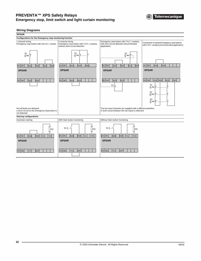
Wiring DiagramsXPSAR
Configurations for the Emergency
1-channel wiringEmergency stop button with one N.C
Not all faults are detected: a short-circuit on the Emergency stonot detected
Starting configurations
Automatic starting
XPSAR
S1
A1 S11 S11
A2 S21 S22
S12B1
B2
XPSAR
A1 S33 Y1
A2 Y1 S37
S34B1
B2
XPSAR Safety modules for emergency stop, switch and light curtain monitoring
stop monitoring function
. contact2-channel wiringEmergency stop button with 2 N.C. contacts, without short-circuit detection
Emergency stop button with 2 N.C. contacts, with short-circuit detection (recommended application)
Connection of several Emergency stop buttons with 2 N.C. contacts (recommended application)
p button is The two input channels are supplied with a different polarities.A short-circuit between the two inputs is detected
With Start button monitoring Without Start button monitoring
S52
XPSAR
S1
A1 S11 S52
A2 S21 S22
S12B1
B2
XPSAR
S1
S1
A1 S11 S11 S52
A2 S21 S22
S12B1
B2
XPSAR
A1 S11
A2 S21 S22S52S11
S12B1
B2
S1
S2
S3
ESC
Y2
S3 ESC
XPSAR
A1 S33 Y1 Y2
A2 Y1 S37
S34B1
B2
S3 ESC
XPSAR
A1 S33 Y1 Y2
A2 Y1 S37
S34B1
B2
© 2003 Schneider Electric All Rights Reserved 05/03
PREVENTA™ XPS Safety RelaysEmergency stop, limit switch and light curtain monitoring
05/03
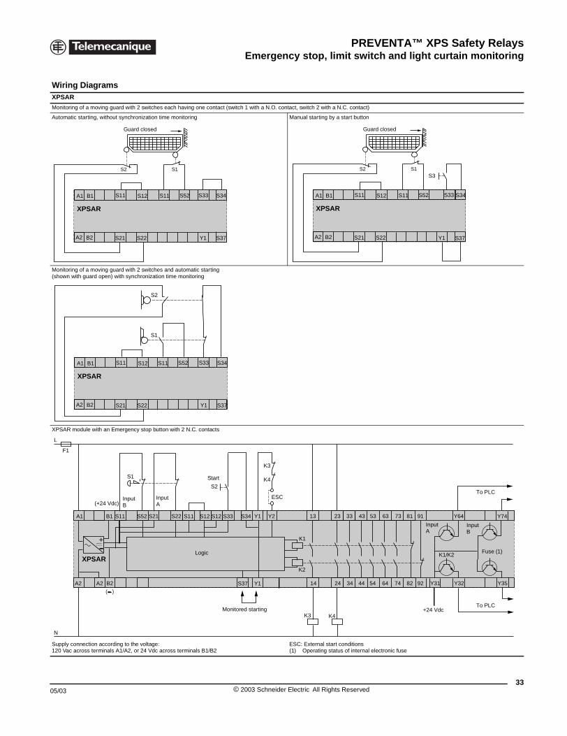
Wiring DiagramsXPSAR
Monitoring of a moving guard with 2
Automatic starting, without synchron
Monitoring of a moving guard with 2(shown with guard open) with synch
XPSAR module with an Emergency
Supply connection according to the 120 Vac across terminals A1/A2, or
XPSAR
A1 S11 S
A2 S21 S
B1
B2
S2
Guard
XPSAR
A1 S11 S
A2 S21 S
B1
B2
F1
L
N
S1
A1
A2 A2
SS11
XPSAR
B1
B2
+
(+24 Vdc)
( )
InputB
XPSAR Safety modules for emergency stop, switch and light curtain monitoring
switches each having one contact (switch 1 with a N.O. contact, switch 2 with a N.C. contact)
ization time monitoring Manual starting by a start button
switches and automatic startingronization time monitoring
stop button with 2 N.C. contacts
voltage: 24 Vdc across terminals B1/B2
ESC: External start conditions(1) Operating status of internal electronic fuse
12
22 Y1 S37
S1
S11 S52 S33 S34
closed
XPSAR
A1 S11 S12
A2 S21 S22
B1
B2
S2
S11 S52 S33 S34
Y1 S37
S1S3
Guard closed
12
22
S11 S52 S33 S34
S1
S2
Y1 S37
K1
K2
2352 S21
14 24
33
34
13
S2
K3
K4
ESC
K4K3
K1/K2
S12S11 S12 S34S33 Y1
S37 Y1
Y2S22 73
74
63
64
53
54
43
44 9282
9181
Y31 Y32
Y64
Y35
Y74
+24 Vdc
Logic
Monitored starting
To PLC
To PLC
Start
InputA
InputA
InputB
Fuse (1)
33© 2003 Schneider Electric All Rights Reserved
PREVENTA™ XPS Safety RelaysEmergency stop, limit switch and light curtain monitoring
34
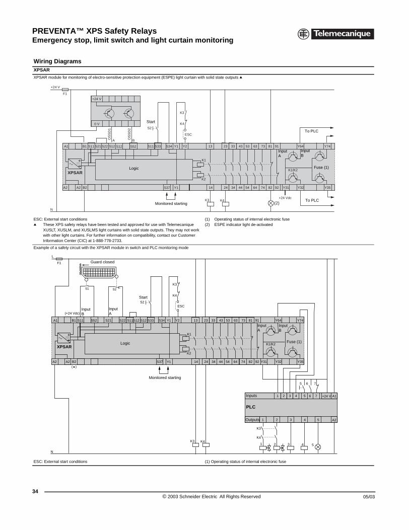
Wiring DiagramsXPSAR
XPSAR module for monitoring of ele
ESC: External start conditionsq These XPS safety relays have
XUSLT, XUSLM, and XUSLMSwith other light curtains. For fuInformation Center (CIC) at 1-8
Example of a safety circuit with the
ESC: External start conditions
+24 V
+24
0
F1
N
A1
A2 A2
S11 S
XPSAR
B1
B2
+
S1
F1
L
N
A1
A2 A2
S52S11
XPSAR
B1
B2
+
( )
(+24 Vdc)InputB
Gua
XPSAR Safety modules for emergency stop, switch and light curtain monitoring
ctro-sensitive protection equipment (ESPE) light curtain with solid state outputs q
been tested and approved for use with Telemecanique light curtains with solid state outputs. They may not work rther information on compatibility, contact our Customer 88-778-2733.
(1) Operating status of internal electronic fuse(2) ESPE indicator light de-activated
XPSAR module in switch and PLC monitoring mode
(1) Operating status of internal electronic fuse
V
V
A BOS
SD
1
OS
SD
2
(2)
K1
K2
23S2221 S12 S12
14 24
33
34
13
K4K3
K1/K2
S11 S34S33 Y1
S37 Y1
Y2 S52 73
74
63
64
53
54
43
44 9282
9181
Y31 Y32
Y64
Y35
Y74
S2K4
K3
ESC
+24 Vdc
Logic
Monitored starting
To PLC
To PLC
Start
InputA
InputB
Fuse (1)
S2
2 31
1 43 5 +24 V
321
2
6 75
A1
A2
76
4 5
4
K4
K3
5
K1
K2
23S21
14 24
33
34
13
S2
K3
K4
ESC
K4K3
K1/K2
S12S11 S12 S34S33 Y1
S37 Y1
Y2S22 73
74
63
64
53
54
43
44 9282
9181
Y31 Y32
Y64
Y35
Y74
Logic
Monitored starting
Start
InputA
InputA
InputB
Fuse (1)
PLC
rd closed
Inputs
Outputs
© 2003 Schneider Electric All Rights Reserved 05/03
PREVENTA™ XPS Safety RelaysEmergency stop, limit switch and light curtain monitoring
05/03
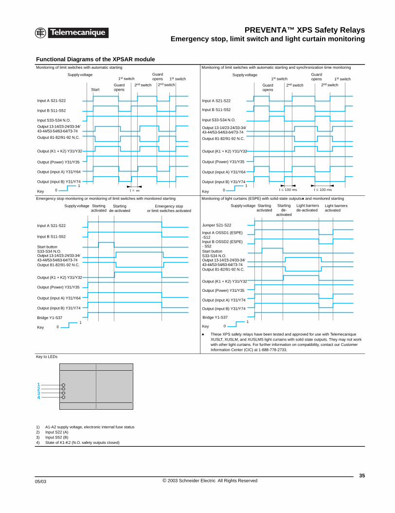
Functional Diagrams oMonitoring of limit switches with auto
Emergency stop monitoring or moni
Key to LEDs
1) A1-A2 supply voltage, electron2) Input S22 (A)3) Input S52 (B)4) State of K1-K2 (N.O. safety ou
1 0
Supply voltage
Key
Input A S21-S22
Input B S11-S52
Input S33-S34 N.O.
Output 13-14/23-24/33-34/43-44/53-54/63-64/73-74
Output 81-82/91-92 N.C.
Output (input B) Y31/Y74
Star
Output (input A) Y31/Y64
Output (Power) Y31/Y35
Output (K1 + K2) Y31/Y32
1 0
Supply voltage
Key
Input A S21-S22
Input B S11-S52
Start buttonS33-S34 N.O.Output 13-14/23-24/33-34/43-44/53-54/63-64/73-74 Output 81-82/91-92 N.C.
Bridge Y1-S37
Staactiv
Output (input A) Y31/Y64
Output (Power) Y31/Y35
Output (K1 + K2) Y31/Y32
Output (input B) Y31/Y74
1234
XPSAR Safety modules for emergency stop, switch and light curtain monitoring
f the XPSAR modulematic starting Monitoring of limit switches with automatic starting and synchronization time monitoring
toring of limit switches with monitored starting Monitoring of light curtains (ESPE) with solid-state outputsq and monitored starting
q These XPS safety relays have been tested and approved for use with Telemecanique XUSLT, XUSLM, and XUSLMS light curtains with solid state outputs. They may not work with other light curtains. For further information on compatibility, contact our Customer Information Center (CIC) at 1-888-778-2733.
ic internal fuse status
tputs closed)
t =
Guard openst
1st switch
2nd switch
Guard opens
2nd switch
1st switch
1 0 t 100 mst 100 ms
Guard opens
Supply voltage
Key
Input A S21-S22
Input B S11-S52
Input S33-S34 N.O.
Output 13-14/23-24/33-34/43-44/53-54/63-64/73-74
Output 81-82/91-92 N.C.
Output (input B) Y31/Y74
1st switch
2nd switch
Guard opens
2nd switch
1st switch
Output (input A) Y31/Y64
Output (Power) Y31/Y35
Output (K1 + K2) Y31/Y32
Startingde-activated
rtingated
Emergency stopor limit switches activated
1 0
Supply voltage
Key
Jumper S21-S22
Input A OSSD1 (ESPE) -S12Input B OSSD2 (ESPE) - S52
Output 13-14/23-24/33-34/43-44/53-54/63-64/73-74 Output 81-82/91-92 N.C.
Output (input B) Y31/Y74
Output (input A) Y31/Y74
Output (Power) Y31/Y35
Output (K1 + K2) Y31/Y32
Bridge Y1-S37
Start buttonS33-S34 N.O.
Startingde-
activated
Startingactivated
Light barriersactivated
Light barriersde-activated
35© 2003 Schneider Electric All Rights Reserved
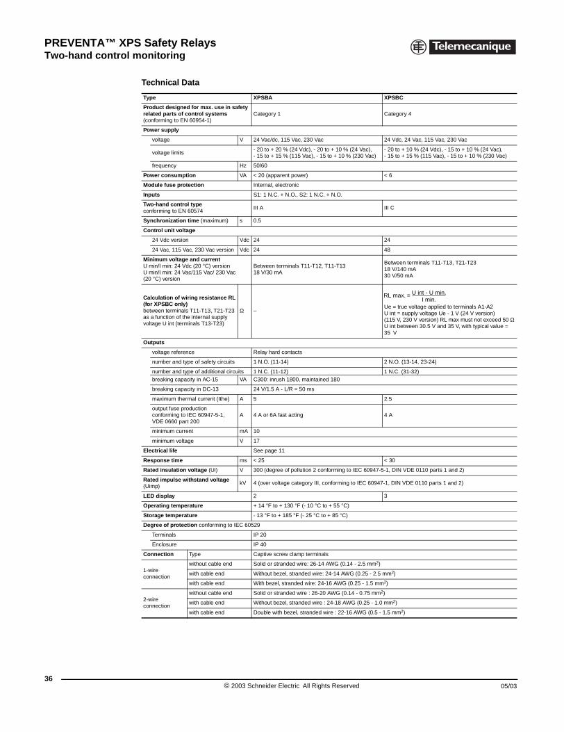
PREVENTA™ XPS Safety RelaysTwo-hand control monitoring
36
XPSBA, BC, BF Safety modules for electrical monitoring of two-hans control stations
Technical Data
Type XPSBA XPSBC
Product designed for max. use in safety related parts of control systems (conforming to EN 60954-1)
Category 1 Category 4
Power supply
voltage V 24 Vac/dc, 115 Vac, 230 Vac 24 Vdc, 24 Vac, 115 Vac, 230 Vac
voltage limits- 20 to + 20 % (24 Vdc), - 20 to + 10 % (24 Vac),- 15 to + 15 % (115 Vac), - 15 to + 10 % (230 Vac)
- 20 to + 10 % (24 Vdc), - 15 to + 10 % (24 Vac), - 15 to + 15 % (115 Vac), - 15 to + 10 % (230 Vac)
frequency Hz 50/60
Power consumption VA < 20 (apparent power) < 6
Module fuse protection Internal, electronic
Inputs S1: 1 N.C. + N.O., S2: 1 N.C. + N.O.
Two-hand control type conforming to EN 60574
III A III C
Synchronization time (maximum) s 0.5
Control unit voltage
24 Vdc version Vdc 24 24
24 Vac, 115 Vac, 230 Vac version Vdc 24 48
Minimum voltage and currentU min/I min: 24 Vdc (20 °C) versionU min/I min: 24 Vac/115 Vac/ 230 Vac(20 °C) version
Between terminals T11-T12, T11-T1318 V/30 mA
Between terminals T11-T13, T21-T2318 V/140 mA30 V/50 mA
Calculation of wiring resistance RL(for XPSBC only) between terminals T11-T13, T21-T23 as a function of the internal supply voltage U int (terminals T13-T23)
Ω –Ue = true voltage applied to terminals A1-A2U int = supply voltage Ue - 1 V (24 V version)(115 V, 230 V version) RL max must not exceed 50 ΩU int between 30.5 V and 35 V, with typical value = 35 V
Outputs
voltage reference Relay hard contacts
number and type of safety circuits 1 N.O. (11-14) 2 N.O. (13-14, 23-24)
number and type of additional circuits 1 N.C. (11-12) 1 N.C. (31-32)breaking capacity in AC-15 VA C300: inrush 1800, maintained 180
breaking capacity in DC-13 24 V/1.5 A - L/R = 50 ms
maximum thermal current (Ithe) A 5 2.5
output fuse productionconforming to IEC 60947-5-1, VDE 0660 part 200
A 4 A or 6A fast acting 4 A
minimum current mA 10
minimum voltage V 17
Electrical life See page 11
Response time ms < 25 < 30
Rated insulation voltage (Ui) V 300 (degree of pollution 2 conforming to IEC 60947-5-1, DIN VDE 0110 parts 1 and 2)
Rated impulse withstand voltage (Uimp)
kV 4 (over voltage category III, conforming to IEC 60947-1, DIN VDE 0110 parts 1 and 2)
LED display 2 3
Operating temperature + 14 °F to + 130 °F (- 10 °C to + 55 °C)
Storage temperature - 13 °F to + 185 °F (- 25 °C to + 85 °C)
Degree of protection conforming to IEC 60529
Terminals IP 20
Enclosure IP 40
Connection Type Captive screw clamp terminals
1-wire connection
without cable end Solid or stranded wire: 26-14 AWG (0.14 - 2.5 mm2)
with cable end Without bezel, stranded wire: 24-14 AWG (0.25 - 2.5 mm2)
with cable end With bezel, stranded wire: 24-16 AWG (0.25 - 1.5 mm2)
2-wire connection
without cable end Solid or stranded wire : 26-20 AWG (0.14 - 0.75 mm2)
with cable end Without bezel, stranded wire : 24-18 AWG (0.25 - 1.0 mm2)
with cable end Double with bezel, stranded wire : 22-16 AWG (0.5 - 1.5 mm2)
RL max. = U int - U min.I min.
© 2003 Schneider Electric All Rights Reserved 05/03
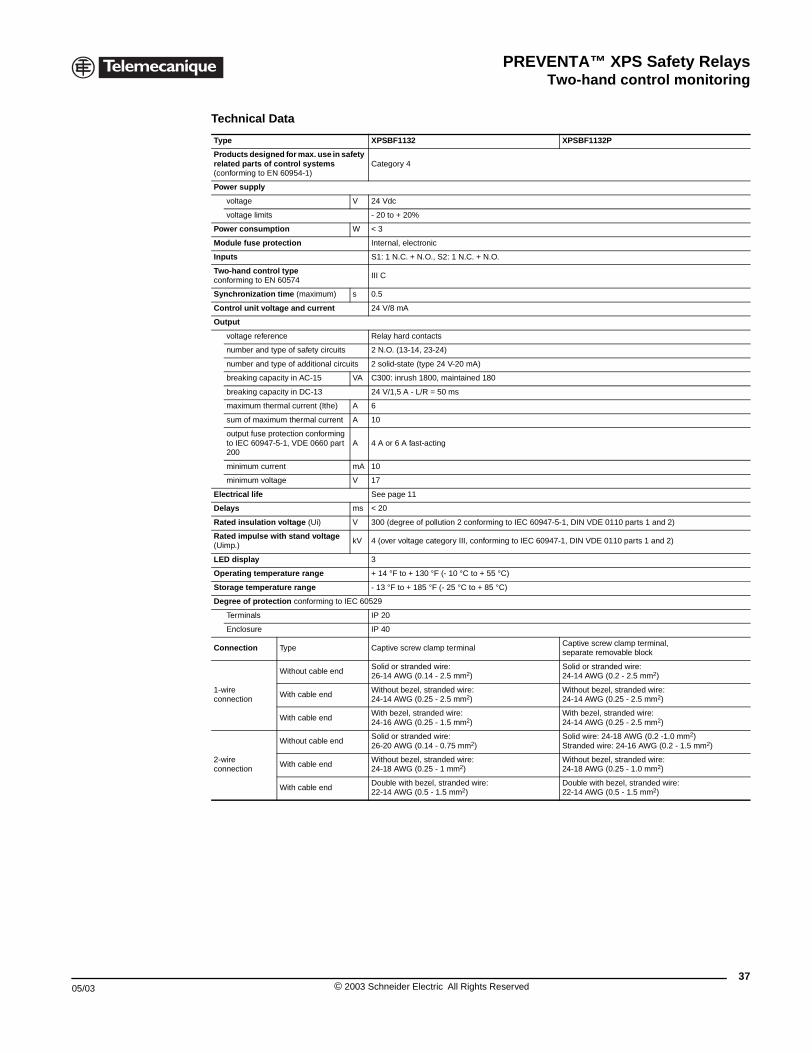
PREVENTA™ XPS Safety RelaysTwo-hand control monitoring
05/03
XPSBA, BC, BF Safety modules for electrical monitoring of two-hans control stations
Technical Data
Type XPSBF1132 XPSBF1132P
Products designed for max. use in safety related parts of control systems (conforming to EN 60954-1)
Category 4
Power supply
voltage V 24 Vdc
voltage limits - 20 to + 20%
Power consumption W < 3
Module fuse protection Internal, electronic
Inputs S1: 1 N.C. + N.O., S2: 1 N.C. + N.O.
Two-hand control type conforming to EN 60574
III C
Synchronization time (maximum) s 0.5
Control unit voltage and current 24 V/8 mA
Output
voltage reference Relay hard contacts
number and type of safety circuits 2 N.O. (13-14, 23-24)
number and type of additional circuits 2 solid-state (type 24 V-20 mA)
breaking capacity in AC-15 VA C300: inrush 1800, maintained 180
breaking capacity in DC-13 24 V/1,5 A - L/R = 50 ms
maximum thermal current (Ithe) A 6
sum of maximum thermal current A 10
output fuse protection conforming to IEC 60947-5-1, VDE 0660 part 200
A 4 A or 6 A fast-acting
minimum current mA 10
minimum voltage V 17
Electrical life See page 11
Delays ms < 20
Rated insulation voltage (Ui) V 300 (degree of pollution 2 conforming to IEC 60947-5-1, DIN VDE 0110 parts 1 and 2)
Rated impulse with stand voltage (Uimp.)
kV 4 (over voltage category III, conforming to IEC 60947-1, DIN VDE 0110 parts 1 and 2)
LED display 3
Operating temperature range + 14 °F to + 130 °F (- 10 °C to + 55 °C)
Storage temperature range - 13 °F to + 185 °F (- 25 °C to + 85 °C)
Degree of protection conforming to IEC 60529
Terminals IP 20
Enclosure IP 40
Connection Type Captive screw clamp terminalCaptive screw clamp terminal, separate removable block
1-wire connection
Without cable endSolid or stranded wire:26-14 AWG (0.14 - 2.5 mm2)
Solid or stranded wire: 24-14 AWG (0.2 - 2.5 mm2)
With cable endWithout bezel, stranded wire: 24-14 AWG (0.25 - 2.5 mm2)
Without bezel, stranded wire: 24-14 AWG (0.25 - 2.5 mm2)
With cable endWith bezel, stranded wire: 24-16 AWG (0.25 - 1.5 mm2)
With bezel, stranded wire: 24-14 AWG (0.25 - 2.5 mm2)
2-wire connection
Without cable endSolid or stranded wire: 26-20 AWG (0.14 - 0.75 mm2)
Solid wire: 24-18 AWG (0.2 -1.0 mm2)Stranded wire: 24-16 AWG (0.2 - 1.5 mm2)
With cable endWithout bezel, stranded wire: 24-18 AWG (0.25 - 1 mm2)
Without bezel, stranded wire: 24-18 AWG (0.25 - 1.0 mm2)
With cable endDouble with bezel, stranded wire: 22-14 AWG (0.5 - 1.5 mm2)
Double with bezel, stranded wire:22-14 AWG (0.5 - 1.5 mm2)
37© 2003 Schneider Electric All Rights Reserved

PREVENTA™ XPS Safety RelaysTwo-hand control monitoring
38
Operating Principle
Two-hand control stations are designed to protect personnel from hand injuries. They require machine operators to keep their hands clear of the hazardous motion area. The use of two-hand control is an individual protective measure, which can protect only one operator. Separate two-hand control units must be provided for each operator in a multiple-worker environment. PREVENTA XPSBA, XPSBC and XPSBF two-hand control safety relays, described below, comply with the requirements of European standard EN 60574 for two-hand control systems.
The control units must be designed and implemented such that they cannot be activated involuntarily or easily rendered inoperative. Depending on the specific application, they must meet the requirements of the Type C standards pertaining to machinery.
To initiate a hazardous motion, both control units (two-hand push buttons) must be activated within an interval of ≤ 0.5 seconds (synchronous activation). If only one of the two push buttons is pressed during a hazardous operation, the control sequence is cancelled. Continuation of the hazardous operation is possible only if both push buttons are returned to their initial position and reactivated within a pre-determined time period. The feedback loop provides self-testing for contactors or relays with mechanically linked contacts designed to increase the number of output contacts or the current switching capacity.
The control sequence does not occur if:
• Both two-hand control push buttons are pressed during a time period greater than 0.5 seconds,
• A short-circuit is present in a push button contact,
• The feedback loop is not closed at start-up.
There must be enough distance between the control units and the hazardous area so that when only one control unit is released, the hazardous area cannot be reached before the hazardous motion stops or the cycle is completed.
XPSBA
This module is designed for use on lighter duty applications where a two-hand control function is desired, but where the safety category is B or 1 (per EN 60954-1) and the two-hand control requirements meet Type III A (per EN 60574). This module is not to be used for applications, such as presses, which require a Type III C module or where the application is not a category B or 1. For press applications, for applications in category 2, 3, or 4, or if application calls for a Type III C module, use XPSBC or XPSBF module.
XPSBC and XPSBF
These modules can be used on applications, such as presses, which require a Type III C module. The XPSBC and XPSBF can be used for a two-hand control application, including presses and similar equipment.
© 2003 Schneider Electric All Rights Reserved 05/03
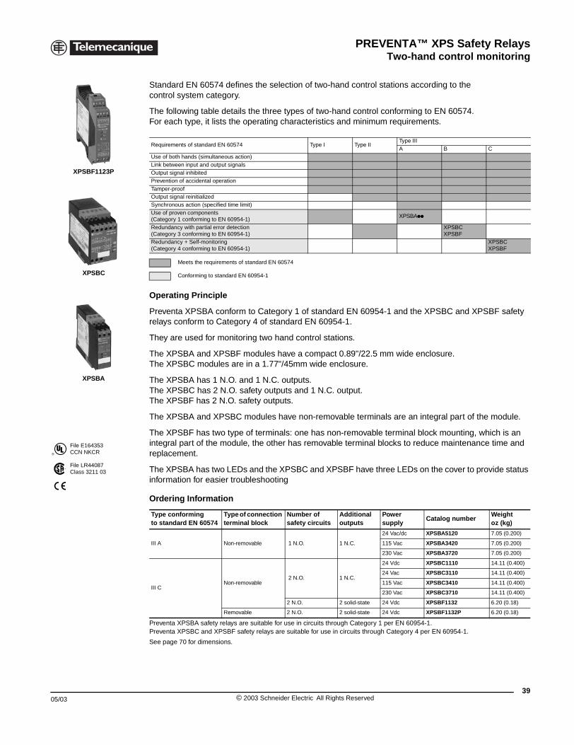
PREVENTA™ XPS Safety RelaysTwo-hand control monitoring
05/03
®
File E164353CCN NKCR
File LR44087Class 3211 03
XPSBF1123P
XPSBC
XPSBA
XPSBA, BC, BF Safety modules for electrical monitoring of two-hans control stations
Standard EN 60574 defines the selection of two-hand control stations according to the control system category.
The following table details the three types of two-hand control conforming to EN 60574.For each type, it lists the operating characteristics and minimum requirements.
Operating Principle
Preventa XPSBA conform to Category 1 of standard EN 60954-1 and the XPSBC and XPSBF safety relays conform to Category 4 of standard EN 60954-1.
They are used for monitoring two hand control stations.
The XPSBA and XPSBF modules have a compact 0.89"/22.5 mm wide enclosure. The XPSBC modules are in a 1.77"/45mm wide enclosure.
The XPSBA has 1 N.O. and 1 N.C. outputs.The XPSBC has 2 N.O. safety outputs and 1 N.C. output.The XPSBF has 2 N.O. safety outputs.
The XPSBA and XPSBC modules have non-removable terminals are an integral part of the module.
The XPSBF has two type of terminals: one has non-removable terminal block mounting, which is an integral part of the module, the other has removable terminal blocks to reduce maintenance time and replacement.
The XPSBA has two LEDs and the XPSBC and XPSBF have three LEDs on the cover to provide status information for easier troubleshooting
Preventa XPSBA safety relays are suitable for use in circuits through Category 1 per EN 60954-1. Preventa XPSBC and XPSBF safety relays are suitable for use in circuits through Category 4 per EN 60954-1.
See page 70 for dimensions.
Requirements of standard EN 60574 Type I Type IIType IIIA B C
Use of both hands (simultaneous action)Link between input and output signalsOutput signal inhibitedPrevention of accidental operationTamper-proofOutput signal reinitializedSynchronous action (specified time limit) Use of proven components(Category 1 conforming to EN 60954-1)
XPSBApp
Redundancy with partial error detection(Category 3 conforming to EN 60954-1)
XPSBCXPSBF
Redundancy + Self-monitoring(Category 4 conforming to EN 60954-1)
XPSBCXPSBF
Meets the requirements of standard EN 60574
Conforming to standard EN 60954-1
Ordering Information
Type conformingto standard EN 60574
Type of connection terminal block
Number of safety circuits
Additionaloutputs
Power supply
Catalog numberWeightoz (kg)
III A Non-removable 1 N.O. 1 N.C.
24 Vac/dc XPSBA5120 7.05 (0.200)
115 Vac XPSBA3420 7.05 (0.200)
230 Vac XPSBA3720 7.05 (0.200)
III CNon-removable
2 N.O. 1 N.C.
24 Vdc XPSBC1110 14.11 (0.400)
24 Vac XPSBC3110 14.11 (0.400)
115 Vac XPSBC3410 14.11 (0.400)
230 Vac XPSBC3710 14.11 (0.400)
2 N.O. 2 solid-state 24 Vdc XPSBF1132 6.20 (0.18)
Removable 2 N.O. 2 solid-state 24 Vdc XPSBF1132P 6.20 (0.18)
39© 2003 Schneider Electric All Rights Reserved
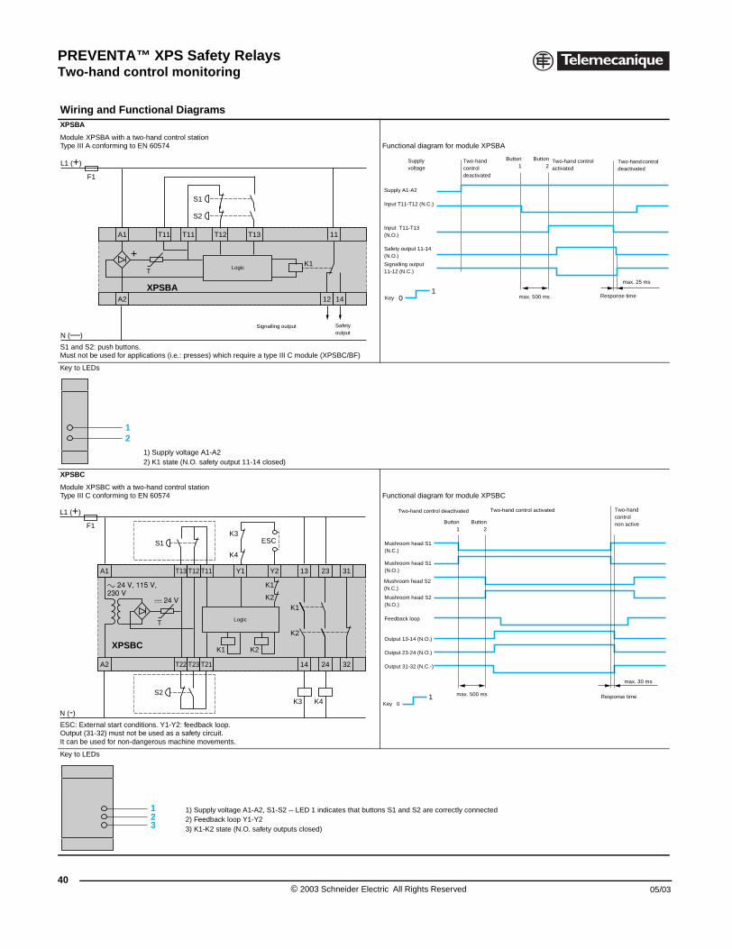
PREVENTA™ XPS Safety RelaysTwo-hand control monitoring
40
Wiring and FunctionalXPSBA
Module XPSBA with a two-hand conType III A conforming to EN 60574
S1 and S2: push buttons.Must not be used for applications (i.
Key to LEDs
1) Supply2) K1 stat
XPSBC
Module XPSBC with a two-hand conType III C conforming to EN 60574
ESC: External start conditions. Y1-YOutput (31-32) must not be used asIt can be used for non-dangerous m
Key to LEDs
A1
A2
T11
F1
L1 (+)
N (—)
T
XPSBA
+
12
A1
A2
F1
L1 (+)
N (-)
T
S1
S2
XPSBC
123
XPSBA, BC, BF Safety modules for electrical monitoring of two-hans control stations
Diagrams
trol stationFunctional diagram for module XPSBA
e.: presses) which require a type III C module (XPSBC/BF)
voltage A1-A2e (N.O. safety output 11-14 closed)
trol stationFunctional diagram for module XPSBC
2: feedback loop. a safety circuit.achine movements.
1) Supply voltage A1-A2, S1-S2 -- LED 1 indicates that buttons S1 and S2 are correctly connected2) Feedback loop Y1-Y2 3) K1-K2 state (N.O. safety outputs closed)
T13 11
12 14
T11 T12
S2
S1
K1Logic
Signalling output Safety output
01
Button1
Button2
Two-hand controldeactivated
max. 500 ms
Supplyvoltage
Key
Two-hand controlactivated
Two-hand control deactivated
max. 25 ms
Response time
Supply A1-A2
Input T11-T12 (N.C.)
Input T11-T13(N.O.)
Safety output 11-14 (N.O.)
Signalling output11-12 (N.C.)
T12 23 31Y2 13
T23 T21T22 14 24 32
T11T13 Y1
K2K1
K1
K2
ESC
K1
K2
K4K3
K3
K4
Logic
1
Two-handcontrolnon active
Two-hand control activatedTwo-hand control deactivated
Mushroom head S1 (N.O.)
Mushroom head S1 (N.C.)
Mushroom head S2(N.C.)
Mushroom head S2 (N.O.)
Feedback loop
Output 13-14 (N.O.)
Output 23-24 (N.O.)
Output 31-32 (N.C.-)
Key 0
max. 500 ms
max. 30 ms
Response time
Button1
Button2
© 2003 Schneider Electric All Rights Reserved 05/03
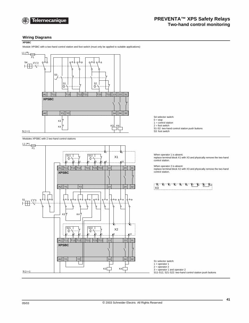
PREVENTA™ XPS Safety RelaysTwo-hand control monitoring
05/03
Wiring Diagrams XPSBC
Module XPSBC with a two-hand con
Modules XPSBC with 2 two-hand co
T11A1
A2
L1 (+)
N (—)
K3
K4
Y
XPSBC
0˚1˚2S4
F1
S3
1˚2˚3
A1
A2
XP
S1
L1 (+)
F1
A1
A2
XP
N (—)
XPSBA, BC, BF Safety modules for electrical monitoring of two-hans control stations
trol station and foot switch (must only be applied to suitable applications)
S4 selector switch:0 = stop1 = control station2 = foot switch S1-S2: two-hand control station push buttonsS3: foot switch
ntrol stations
When operator 1 is absent:replace terminal block X1 with X3 and physically remove the two-hand control station.
When operator 2 is absent:replace terminal block X2 with X3 and physically remove the two-hand control station.
S1 selector switch:1 = operator 12 = operator 23 = operator 1 and operator 2S11-S12, S21-S22: two-hand control station push buttons
T13
1 Y2
13 23 31
14 24 32
T12
K4K3
T21 T23 T22
S1 S2
10
T13
Y1 Y2
13 23 31
14 24 32
SBC
T12 T21 T22T23
K3 K4
T11
S21 S22
S12S11
T13
Y1 Y2
13 23 31
14 24 32
SBC
T12 T21 T22T23T11
X2
K4K3
97
X1
97
864321 5
10864321 5
X31 2 3 4 5 6 7 8 9 10
41© 2003 Schneider Electric All Rights Reserved
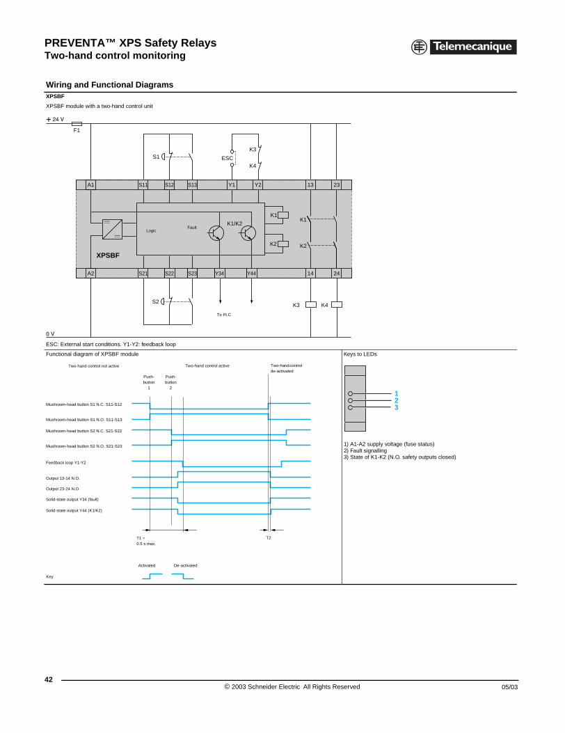
PREVENTA™ XPS Safety RelaysTwo-hand control monitoring
42
Wiring and Functional XPSBF
XPSBF module with a two-hand con
ESC: External start conditions. Y1-Y
Functional diagram of XPSBF modu
A1
A2
F1
XPSBF
Two-hand control not active
Mushroom-head button S1 N.O. S11-S13
Mushroom-head button S1 N.C. S11-S12
Mushroom-head button S2 N.C. S21-S22
Mushroom-head button S2 N.O. S21-S23
Feedback loop Y1-Y2
Output 13-14 N.O.
Output 23-24 N.O.
Solid-state output Y34 (fault)
Key
Solid-state output Y44 (K1/K2)
XPSBA, BC, BF Safety modules for electrical monitoring of two-hans control stations
Diagrams
trol unit
2: feedback loop
le Keys to LEDs
1) A1-A2 supply voltage (fuse status)2) Fault signalling3) State of K1-K2 (N.O. safety outputs closed)
S12 23Y2 13
S22 S23 Y34 Y44S21 14 24
S13S11 Y1
K2
K1
K1/K2K1
K2
K4K3
K1/K2
K3
K4ESCS1
S2
To PLC
FaultLogic
Push-button
1
Push-button
2
Two-hand control de-activated
Two-hand control active
T1 =0.5 s max.
T2
Activated De-activated
123
© 2003 Schneider Electric All Rights Reserved 05/03
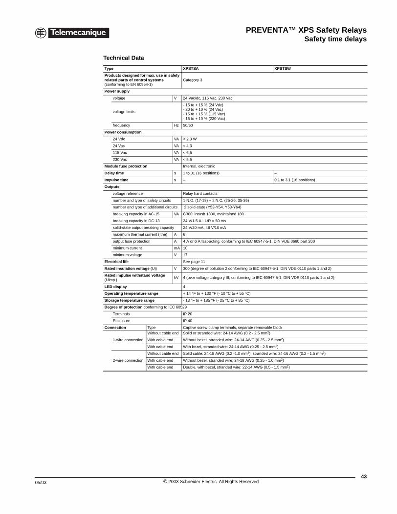
PREVENTA™ XPS Safety RelaysSafety time delays
05/03
XPSTSA, TSW Safety modules for safety time delays
Technical Data
Type XPSTSA XPSTSW
Products designed for max. use in safety related parts of control systems (conforming to EN 60954-1)
Category 3
Power supply
voltage V 24 Vac/dc, 115 Vac, 230 Vac
voltage limits
- 15 to + 15 % (24 Vdc)- 20 to + 10 % (24 Vac)- 15 to + 15 % (115 Vac)- 15 to + 10 % (230 Vac)
frequency Hz 50/60
Power consumption
24 Vdc VA < 2.3 W
24 Vac VA < 4.3
115 Vac VA < 6.5
230 Vac VA < 5.5
Module fuse protection Internal, electronic
Delay time s 1 to 31 (16 positions) –
Impulse time s – 0.1 to 3.1 (16 positions)
Outputs
voltage reference Relay hard contacts
number and type of safety circuits 1 N.O. (17-18) + 2 N.C. (25-26, 35-36)
number and type of additional circuits 2 solid-state (Y53-Y54, Y53-Y64)
breaking capacity in AC-15 VA C300: inrush 1800, maintained 180
breaking capacity in DC-13 24 V/1.5 A - L/R = 50 ms
solid-state output breaking capacity 24 V/20 mA, 48 V/10 mA
maximum thermal current (Ithe) A 6
output fuse protection A 4 A or 6 A fast-acting, conforming to IEC 60947-5-1, DIN VDE 0660 part 200
minimum current mA 10
minimum voltage V 17
Electrical life See page 11
Rated insulation voltage (Ui) V 300 (degree of pollution 2 conforming to IEC 60947-5-1, DIN VDE 0110 parts 1 and 2)
Rated impulse withstand voltage (Uimp.)
kV 4 (over voltage category III, conforming to IEC 60947-5-1, DIN VDE 0110 parts 1 and 2)
LED display 4
Operating temperature range + 14 °F to + 130 °F (- 10 °C to + 55 °C)
Storage temperature range - 13 °F to + 185 °F (- 25 °C to + 85 °C)
Degree of protection conforming to IEC 60529
Terminals IP 20
Enclosure IP 40
Connection Type Captive screw clamp terminals, separate removable block
1-wire connection
Without cable end Solid or stranded wire: 24-14 AWG (0.2 - 2.5 mm2)
With cable end Without bezel, stranded wire: 24-14 AWG (0.25 - 2.5 mm2)
With cable end With bezel, stranded wire: 24-14 AWG (0.25 - 2.5 mm2)
2-wire connection
Without cable end Solid cable: 24-18 AWG (0.2 -1.0 mm2), stranded wire: 24-16 AWG (0.2 - 1.5 mm2)
With cable end Without bezel, stranded wire: 24-18 AWG (0.25 - 1.0 mm2)
With cable end Double, with bezel, stranded wire: 22-14 AWG (0.5 - 1.5 mm2)
43© 2003 Schneider Electric All Rights Reserved
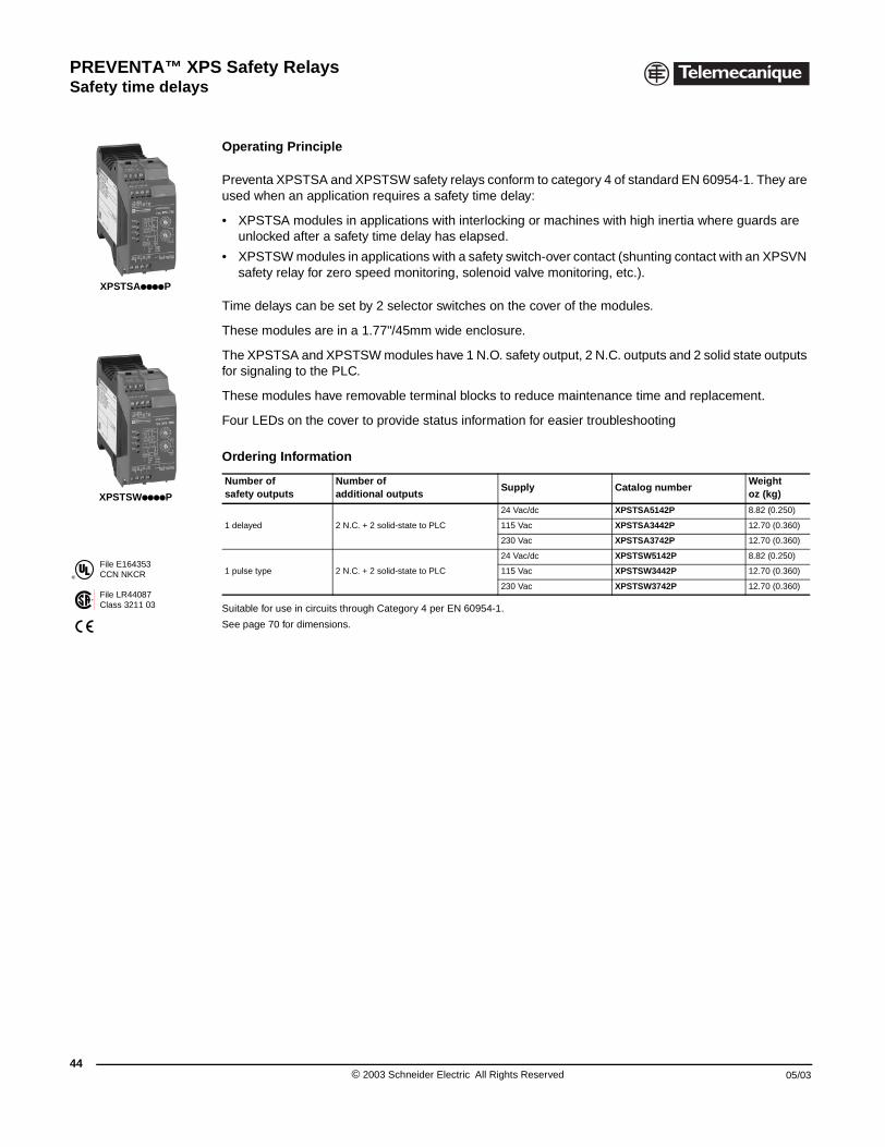
PREVENTA™ XPS Safety RelaysSafety time delays
44
®
File E164353CCN NKCR
File LR44087Class 3211 03
XPSTSAppppP
XPSTSWppppP
XPSTSA, TSW Safety modules for safety time delays
Operating Principle
Preventa XPSTSA and XPSTSW safety relays conform to category 4 of standard EN 60954-1. They are used when an application requires a safety time delay:
• XPSTSA modules in applications with interlocking or machines with high inertia where guards are unlocked after a safety time delay has elapsed.
• XPSTSW modules in applications with a safety switch-over contact (shunting contact with an XPSVN safety relay for zero speed monitoring, solenoid valve monitoring, etc.).
Time delays can be set by 2 selector switches on the cover of the modules.
These modules are in a 1.77"/45mm wide enclosure.
The XPSTSA and XPSTSW modules have 1 N.O. safety output, 2 N.C. outputs and 2 solid state outputs for signaling to the PLC.
These modules have removable terminal blocks to reduce maintenance time and replacement.
Four LEDs on the cover to provide status information for easier troubleshooting
Suitable for use in circuits through Category 4 per EN 60954-1.
See page 70 for dimensions.
Ordering Information
Number of safety outputs
Number of additional outputs
Supply Catalog numberWeightoz (kg)
1 delayed 2 N.C. + 2 solid-state to PLC
24 Vac/dc XPSTSA5142P 8.82 (0.250)
115 Vac XPSTSA3442P 12.70 (0.360)
230 Vac XPSTSA3742P 12.70 (0.360)
1 pulse type 2 N.C. + 2 solid-state to PLC
24 Vac/dc XPSTSW5142P 8.82 (0.250)
115 Vac XPSTSW3442P 12.70 (0.360)
230 Vac XPSTSW3742P 12.70 (0.360)
© 2003 Schneider Electric All Rights Reserved 05/03
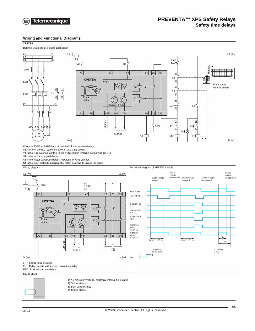
PREVENTA™ XPS Safety RelaysSafety time delays
05/03
Wiring and Functional XPSTSA
Delayed unlocking of a guard applica
Contacts 95/96 and 97/98 are trip coS1 is one of the N.C. safety contactsY1 is the N.C. solenoid contact in thS2 is the motor stop push buttonS3 is the motor start push button, inS4 is the push button to energize the
Wiring diagram
1) Signal to be delayed.2) Relay outputs with inrush curreESC: External start conditions.
Key to LEDs
KM1
L1 L1
FM2
PE PE
PEV WU
FM1
U W PEV
M 3
9897
9695
L2 L2L3 L3
14
13
A1
A2 PE
F1
L1 (+)
+
N ( )
(1)
T
KM1
XPSTSAL
1234
XPSTSA, TSW Safety modules for safety time delays
Diagrams
tion
ntacts for an overload relay. in an XCSE switch
e XCSE switch (wired in series with the S1)
parallel of KM1 contact XCSE solenoid to unlock the guard
Functional diagram of XPSTSA module
nt time delay.
1) A1-A2 supply voltage, electronic internal fuse status2) Output status3) Start button status4) Timing status
A1 25 35Y2 17
A2 18PE Y53 Y54 Y64 26 36
Y1
F1
L1 (+) L1 (+)
+
N ( ) N ( )
K1/K2 F OK
K2
K2
K3
S3
1413
KM1
T
KM1 K3
KM1
XPSTSA
1 2
S4
1413
Y1
S2
2221
S1
2221
Y1
5251
FM2
K3
H1
+24
Vdc
To PLC
LogicXCSE safety interlock switch
ESC
25 35Y2 17
18Y53 Y54 Y64 26 36
Y1
L1 (+)
N ( )
(2)
K1/K2 F OK
K2
K21 2
+ 2
4 V
dc
To PLC
ogic
10
tv = 1...31 s tv = 1...31 ste
tv
Key
Supply voltagede-activatedSupply voltage
activated
Input A1-A2
Input Y1-Y2
Output 17-18 N.O.
SignallingoutputY53-Y54
Supply voltageactivated
Supply voltagede-activated
Supply voltagede-activated
Output 25-26 N.C.
Output 35-36 N.C.
SignallingoutputY53-Y64
No startingY1-Y2 open
No startingte < tv
45© 2003 Schneider Electric All Rights Reserved
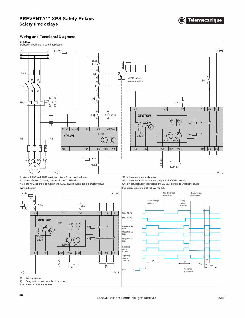
PREVENTA™ XPS Safety RelaysSafety time delays
46
Wiring and Functional XPSTSWDelayed unlocking of a guard applic
Contacts 95/96 and 97/98 are trip coS1 is one of the N.C. safety contactsY1 is the N.C. solenoid contact in th
Wiring diagram
1) Control signal.2) Relay outputs with impulse timESC: External start conditions.
L1 (
F0
4
L1 L1
FM2
PE PE
PEV WU
FM1
U W PEV
2 64
1 53
M 3
9897
9695
L2 L2L3 L3
14
13
A1
A2 PE
F1
L1 (+)
T
KM1
XPSTSW
(1)
L
XPSTSA, TSW Safety modules for safety time delays
Diagrams
ation
ntacts for an overload relay. in an XCSE switch
e XCSE switch (wired in series with the S1)
S2 is the motor stop push buttonS3 is the motor start push button, in parallel of KM1 contactS4 is the push button to energize the XCSE solenoid to unlock the guard
Functional diagram of XPSTSW module
e delay.
A1 25 35Y2 17
A2 18PE Y53 Y54 Y64 26 36
Y1
+) L1 (+)
+
K1/K2 F OK
K2
K2
S3 KM1
1413
T
KM1
XPSTSW
1 2
A1 Z1 Z2 Z3 Y33/Y43
A2 22 Y34
21
14
13
Y44
A1/A2XPSVN
S4
1413
Y1
KM1
S222
21
S1
2221
Y1
5251
FM2
S4
1413
+ 2
4 V
dc
To PLC
XCSE safety interlock switch
ESC
25 35Y2 17
18Y53 Y54 Y64 26 36
Y1
L1 (+)
K1/K2 F OK
K2
K21 2
(2)+ 2
4 V
dc
To PLC
ogic
tw te
te
10
tw
tw
Key
Supply voltagede-activated
Supply voltageactivated
Input A1-A2
Input Y1-Y2
Output 17-18 N.O.
SignallingoutputY53-Y64
Supply voltageactivated
Supply voltagede-activated
Output 25-26 N.C.
Output 35-36 N.C.
No startingY1-Y2 open
SignallingoutputY53-Y54
© 2003 Schneider Electric All Rights Reserved 05/03
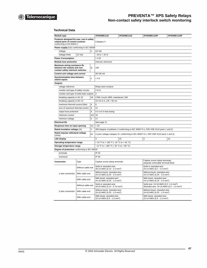
PREVENTA™ XPS Safety RelaysNon-contact safety interlock switch monitoring
05/03
XPSDMB, XPSDME Safety modules for monitoring of encoded magnetic switches
Technical Data
Module type XPSDMB1132 XPSDME1132 XPSDMB1132P XPSDME1132P
Products designed for max. use in safety related parts of control systems conforming to EN 60954-1
Category 4
Power supply (Ue) conforming to IEC 60038
Voltage V 24 Vdc
Voltage limits 24 Vdc - 20 to + 20 %
Power Consumption < 3 W
Module fuse protection Internal, electronic
Maximum wiring resistance RL between the module and non-contact safety interlock switches
Ω 100
Control unit voltage and current 28 V/8 mA
Synchronization time between switch inputs s < 0.5
Outputs
voltage reference Relay hard contacts
number and type of safety circuits 2 N.O.
number and type of solid-state outputs 2
breaking capacity in AC-15 VA C300: inrush 1800, maintained: 180
breaking capacity in DC-13 24 V/1.5 A, L/R = 50 ms
maximum thermal current (Ithe) A 6
sum of maximum thermal current A 12
output fuse protection A 4 A or 6 A fast-acting
minimum current mA 10
minimum voltage V 17
Electrical life See page 11
Response time on input opening ms < 20
Rated insulation voltage (Ui) V 300 (degree of pollution 2 conforming to IEC 60947-5-1, DIN VDE 0110 parts 1 and 2)
Rated impulse withstand voltage (Uimp)
kV 4 (over voltage category III, conforming to IEC 60947-5-1, DIN VDE 0110 parts 1 and 2)
LED display 3 15 3 15
Operating temperature range + 14 °F to + 130 °F (- 10 °C to + 55 °C)
Storage temperature range - 13 °F to + 185 °F (- 25 °C to + 85 °C)
Degree of protection conforming to IEC 60529
terminals IP 20
enclosure IP 40
Connection Type Captive screw clamp terminalsCaptive screw clamp terminals, separate removable terminal block
1-wire connection
Without cable endSolid or stranded wire: 26-14 AWG (0.14 - 2.5 mm2)
Solid or stranded wire: 24-14 AWG (0.2 - 2.5 mm2)
With cable endWithout bezel, stranded wire: 24-14 AWG (0.25 - 2.5 mm2)
Without bezel, stranded wire: 24-14 AWG (0.25 - 2.5 mm2)
With cable endWith bezel, stranded wire: 24-16 AWG (0.25 - 1.5 mm2)
With bezel, stranded wire: 24-14 AWG (0.25 - 2.5 mm2)
2-wire connection
Without cable endSolid or stranded wire: 26-20 AWG (0.14 - 0.75 mm2)
Solid wire: 24-18 AWG (0.2 -1.0 mm2)Stranded wire: 24-16 AWG (0.2 - 1.5 mm2)
With cable endWithout bezel, stranded wire: 24-18 AWG (0.25 - 1.0 mm2)
Without bezel, stranded wire: 24-18 AWG (0.25 - 1.0 mm2)
With cable endWith bezel, stranded wire: 22-14 AWG (0.5 - 1.5 mm2)
With bezel, stranded wire: 22-14 AWG (0.5 - 1.5 mm2)
47© 2003 Schneider Electric All Rights Reserved
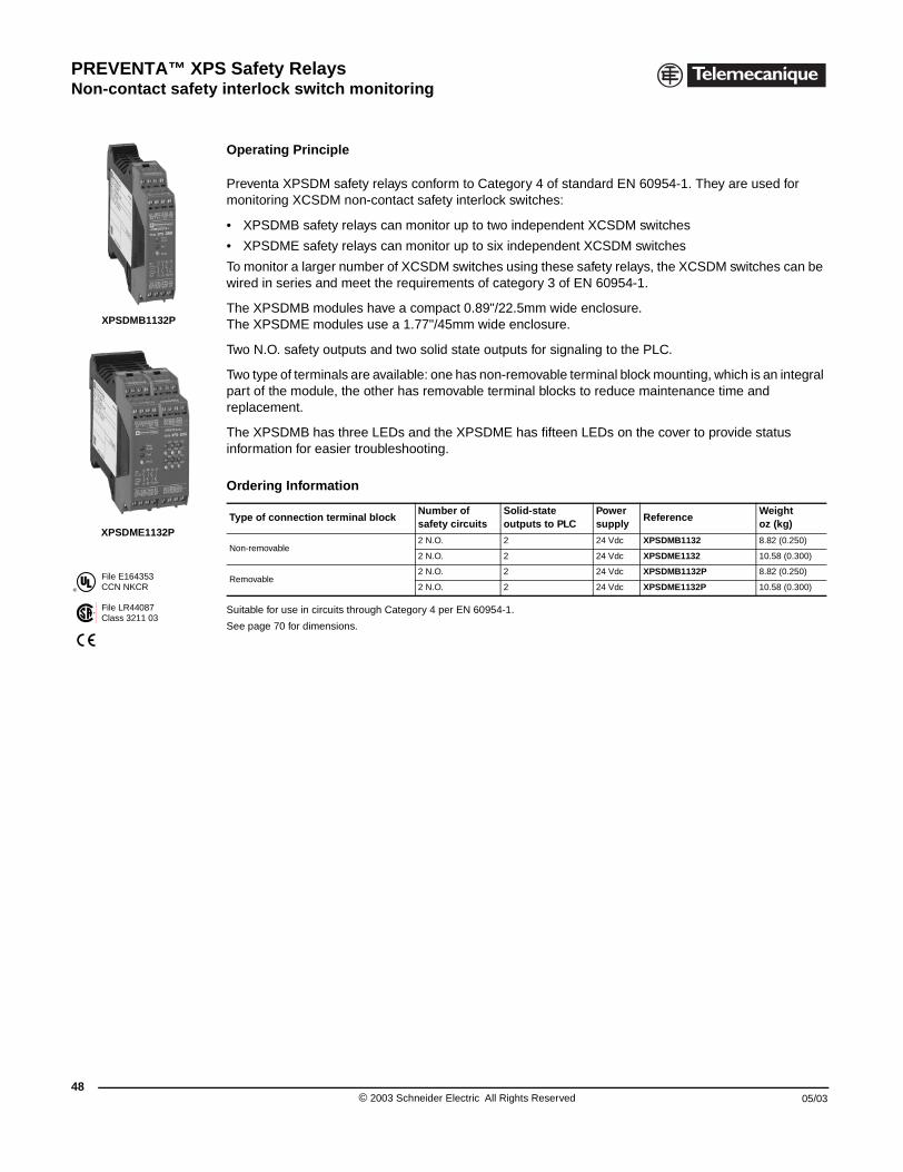
PREVENTA™ XPS Safety RelaysNon-contact safety interlock switch monitoring
48
®
File E164353CCN NKCR
File LR44087Class 3211 03
XPSDMB1132P
XPSDME1132P
XPSDMB, XPSDME Safety modules for monitoring of encoded magnetic switches
Operating Principle
Preventa XPSDM safety relays conform to Category 4 of standard EN 60954-1. They are used for monitoring XCSDM non-contact safety interlock switches:
• XPSDMB safety relays can monitor up to two independent XCSDM switches
• XPSDME safety relays can monitor up to six independent XCSDM switches
To monitor a larger number of XCSDM switches using these safety relays, the XCSDM switches can be wired in series and meet the requirements of category 3 of EN 60954-1.
The XPSDMB modules have a compact 0.89"/22.5mm wide enclosure.The XPSDME modules use a 1.77"/45mm wide enclosure.
Two N.O. safety outputs and two solid state outputs for signaling to the PLC.
Two type of terminals are available: one has non-removable terminal block mounting, which is an integral part of the module, the other has removable terminal blocks to reduce maintenance time and replacement.
The XPSDMB has three LEDs and the XPSDME has fifteen LEDs on the cover to provide status information for easier troubleshooting.
Suitable for use in circuits through Category 4 per EN 60954-1.
See page 70 for dimensions.
Ordering Information
Type of connection terminal blockNumber of safety circuits
Solid-state outputs to PLC
Power supply
ReferenceWeightoz (kg)
Non-removable2 N.O. 2 24 Vdc XPSDMB1132 8.82 (0.250)
2 N.O. 2 24 Vdc XPSDME1132 10.58 (0.300)
Removable2 N.O. 2 24 Vdc XPSDMB1132P 8.82 (0.250)
2 N.O. 2 24 Vdc XPSDME1132P 10.58 (0.300)
© 2003 Schneider Electric All Rights Reserved 05/03
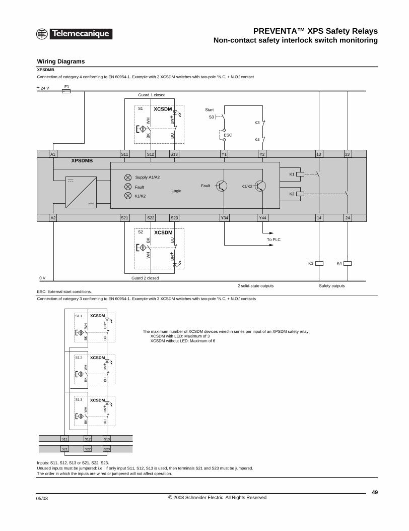
PREVENTA™ XPS Safety RelaysNon-contact safety interlock switch monitoring
05/03
Wiring Diagrams XPSDMB
Connection of category 4 conformin
ESC: External start conditions.
Connection of category 3 conformin
Inputs: S11, S12, S13 or S21, S22, Unused inputs must be jumpered: i.eThe order in which the inputs are wi
A1
A2
XPSDMB
F1+ 24 V
0 V
S11 S12
S1.3 XCSD
BK
WH
S1.2 XCSD
BK
WH
S1.1 XCSD
BK
WH
S21 S22
XPSDMB, XPSDME Safety modules for monitoring of encoded magnetic switches
g to EN 60954-1. Example with 2 XCSDM switches with two-pole “N.C. + N.O.” contact
g to EN 60954-1. Example with 3 XCSDM switches with two-pole “N.C. + N.O.” contacts
S23..: if only input S11, S12, S13 is used, then terminals S21 and S23 must be jumpered.
red or jumpered will not affect operation.
Y1 Y2 13S11 S12 S13
S1 XCSDM
K4
K3
K1
K3
K2
K1/K2
BK
WH
K4
BU
BN+
Y34 Y44 14
23
24S21 S22 S23
K1/K2
S2 XCSDM
WH
BK
BN+
BU
S3
ESC
Start
Logic
Supply A1/A2
Fault Fault
Safety outputs
To PLC
2 solid-state outputs
Guard 2 closed
Guard 1 closed
S13
M
BU
BN+
M
BU
BN+
M
BU
BN+
S23
The maximum number of XCSDM devices wired in series per input of an XPSDM safety relay:XCSDM with LED: Maximum of 3XCSDM without LED: Maximum of 6
49© 2003 Schneider Electric All Rights Reserved
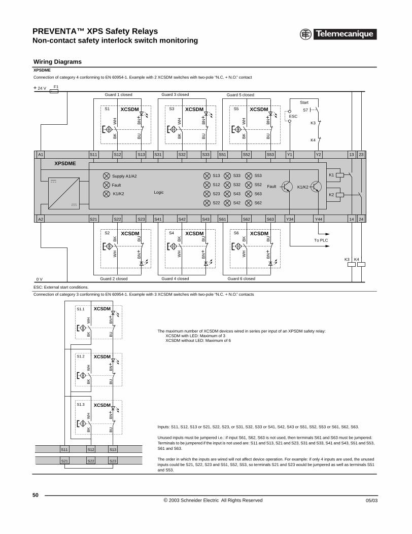
PREVENTA™ XPS Safety RelaysNon-contact safety interlock switch monitoring
50
Wiring Diagrams XPSDME
Connection of category 4 conformin
ESC: External start conditions.
Connection of category 3 conformin
A1 S11
A2 S21
XPSDME
F1+ 24 V
0 V
S11 S12
S1.3 XC
BK
WH
S1.2 XC
BK
WH
S1.1 XC
BK
WH
S21 S22
XPSDMB, XPSDME Safety modules for monitoring of encoded magnetic switches
g to EN 60954-1. Example with 2 XCSDM switches with two-pole “N.C. + N.O.” contact
g to EN 60954-1. Example with 3 XCSDM switches with two-pole “N.C. + N.O.” contacts
The maximum number of XCSDM devices wired in series per input of an XPSDM safety relay:XCSDM with LED: Maximum of 3XCSDM without LED: Maximum of 6
Inputs: S11, S12, S13 or S21, S22, S23, or S31, S32, S33 or S41, S42, S43 or S51, S52, S53 or S61, S62, S63.
Unused inputs must be jumpered i.e.: if input S61, S62, S63 is not used, then terminals S61 and S63 must be jumpered. Terminals to be jumpered if the input is not used are: S11 and S13, S21 and S23, S31 and S33, S41 and S43, S51 and S53, S61 and S63.
The order in which the inputs are wired will not affect device operation. For example: if only 4 inputs are used, the unused inputs could be S21, S22, S23 and S51, S52, S53, so terminals S21 and S23 would be jumpered as well as terminals S51 and S53.
Y1 Y2 13S12 S13
S1 XCSDM XCSDM XCSDM
K4
K3
K1
K3
K2
K1/K2
BK
WH
BU
BN+
S31 S32 S33
S3
BK
WH
BU
BN+
S51 S52 S53
Y34 Y44 14
23
K4
24S22 S23 S41 S42 S43 S61 S62 S63
S13
S12
S23
S22
K1/K2
S53
S52
S63
S62
S33
S32
S43
S42
S5
BK
WH
BU
BN+
S2 XCSDM
WH
BK
BN+
BU
S4 XCSDM
WH
BK
BN+
BU
S6 XCSDM
WH
BK
BN+
BU
S7
ESC
Start
Logic
Supply A1/A2
Fault Fault
To PLC
Guard 2 closed
Guard 1 closed
Guard 4 closed Guard 6 closed
Guard 3 closed Guard 5 closed
S13
SDM
BU
BN+
SDM
BU
BN+
SDM
BU
BN+
S23
© 2003 Schneider Electric All Rights Reserved 05/03
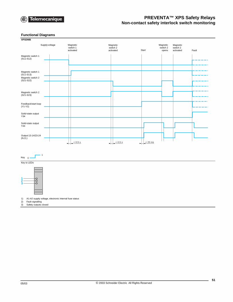
PREVENTA™ XPS Safety RelaysNon-contact safety interlock switch monitoring
05/03
Functional Diagrams XPSDMB
Key to LEDs
1) A1-A2 supply voltage, electron2) Fault signalling3) Safety outputs closed
10
Supply voltage
Key
Magnetic switch 1(S11-S12)
Output 13-14/23-24 (N.O.)
Magnetic switch 1(S11-S13)Magnetic switch 2(S21-S22)
Magnetic switch 2(S21-S23)
Solid-state output Y44
Solid-state output Y34
Feedback/start loop (Y1-Y2)
123
XPSDMB, XPSDME Safety modules for monitoring of encoded magnetic switches
ic internal fuse status
< 0,5 s < 0,5 s < 20 ms
Magnetic switch 1 activated
Magnetic switch 2 activated Start Fault
Magneticswitch 2
opens
Magnetic switch 2 activated
51© 2003 Schneider Electric All Rights Reserved
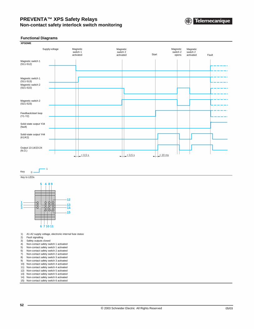
PREVENTA™ XPS Safety RelaysNon-contact safety interlock switch monitoring
52
Functional Diagrams XPSDME
Key to LEDs
1) A1-A2 supply voltage, electron2) Fault signalling3) Safety outputs closed4) Non-contact safety switch 1 ac5) Non-contact safety switch 1 ac6) Non-contact safety switch 2 ac7) Non-contact safety switch 2 ac8) Non-contact safety switch 3 ac9) Non-contact safety switch 3 ac10) Non-contact safety switch 4 ac11) Non-contact safety switch 4 ac12) Non-contact safety switch 5 ac13) Non-contact safety switch 5 ac14) Non-contact safety switch 6 ac15) Non-contact safety switch 6 ac
1 0
Supply voltage
Key
Magnetic switch 1(S11-S12)
Output 13-14/23-24 (N.O.)
Magnetic switch 1(S11-S13)Magnetic switch 2(S21-S22)
Magnetic switch 2(S21-S23)
Solid-state output Y44(K1/K2)
Solid-state output Y34(fault)
Feedback/start loop (Y1-Y2)
12
45 8 9
76 10 11
3
XPSDMB, XPSDME Safety modules for monitoring of encoded magnetic switches
ic internal fuse status
tivatedtivatedtivatedtivatedtivatedtivatedtivatedtivatedtivatedtivatedtivatedtivated
< 0,5 s < 0,5 s < 20 ms
Magnetic switch 1 activated
Magnetic switch 2 activated Start Fault
Magneticswitch 2
opens
Magnetic switch 2activated
12
131415
© 2003 Schneider Electric All Rights Reserved 05/03
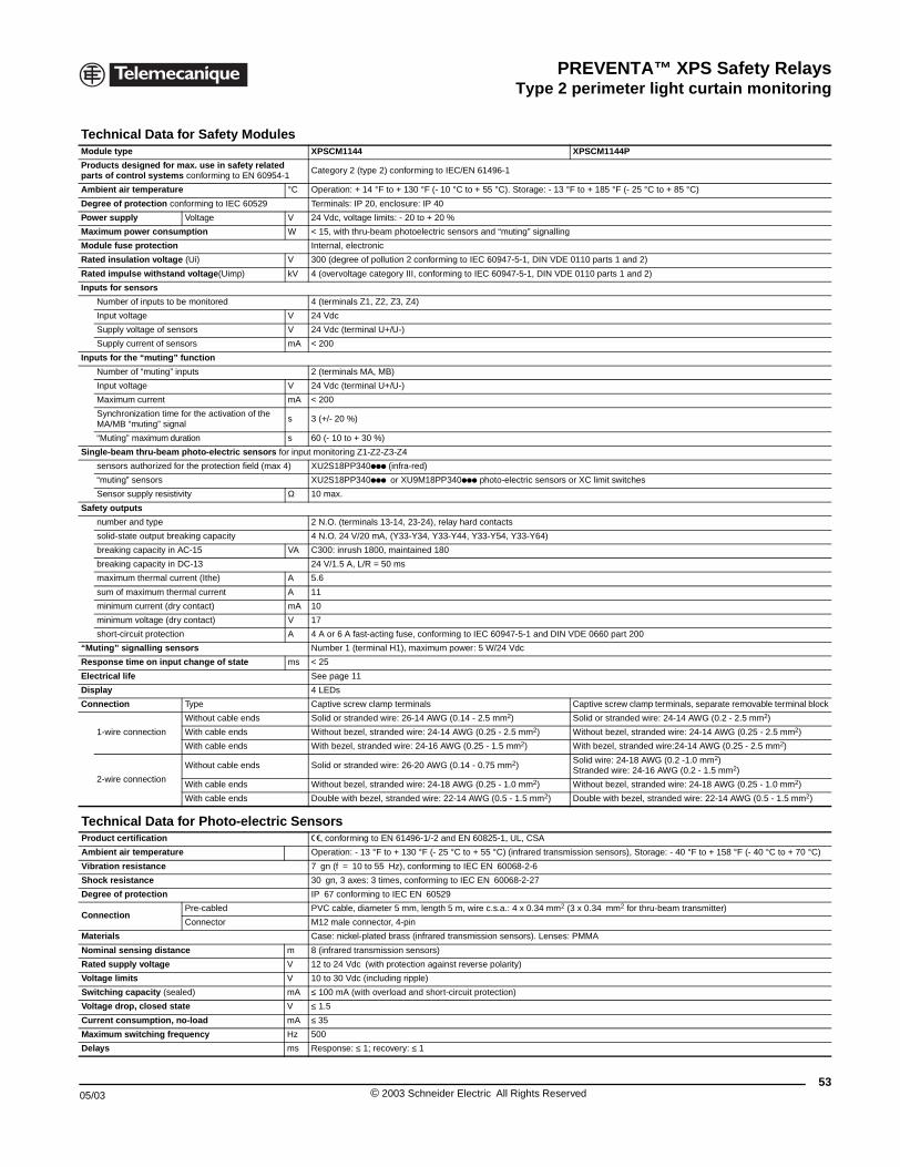
PREVENTA™ XPS Safety RelaysType 2 perimeter light curtain monitoring
05/03
Technical Data for SafeModule type
Products designed for max. use inparts of control systems conformin
Ambient air temperature
Degree of protection conforming to
Power supply Voltage
Maximum power consumption
Module fuse protection
Rated insulation voltage (Ui)
Rated impulse withstand voltage(
Inputs for sensors
Number of inputs to be monitore
Input voltage
Supply voltage of sensors
Supply current of sensors
Inputs for the “muting” function
Number of “muting” inputs
Input voltage
Maximum current
Synchronization time for the actiMA/MB “muting” signal
“Muting” maximum duration
Single-beam thru-beam photo-ele
sensors authorized for the prote
“muting” sensors
Sensor supply resistivity
Safety outputs
number and type
solid-state output breaking capa
breaking capacity in AC-15
breaking capacity in DC-13
maximum thermal current (Ithe)
sum of maximum thermal curren
minimum current (dry contact)
minimum voltage (dry contact)
short-circuit protection
“Muting” signalling sensors
Response time on input change o
Electrical life
Display
Connection Type
1-wire connection
Without c
With cable
With cable
2-wire connection
Without c
With cable
With cable
Technical Data for PhoProduct certification
Ambient air temperature
Vibration resistance
Shock resistance
Degree of protection
ConnectionPre-cable
Connecto
Materials
Nominal sensing distance
Rated supply voltage
Voltage limits
Switching capacity (sealed)
Voltage drop, closed state
Current consumption, no-load
Maximum switching frequency
Delays
XPSCM Safety modules and photo-electric sendors with abuilt-in muting function
ty ModulesXPSCM1144 XPSCM1144P
safety related g to EN 60954-1
Category 2 (type 2) conforming to IEC/EN 61496-1
°C Operation: + 14 °F to + 130 °F (- 10 °C to + 55 °C). Storage: - 13 °F to + 185 °F (- 25 °C to + 85 °C)
IEC 60529 Terminals: IP 20, enclosure: IP 40
V 24 Vdc, voltage limits: - 20 to + 20 %
W < 15, with thru-beam photoelectric sensors and “muting” signalling
Internal, electronic
V 300 (degree of pollution 2 conforming to IEC 60947-5-1, DIN VDE 0110 parts 1 and 2)
Uimp) kV 4 (overvoltage category III, conforming to IEC 60947-5-1, DIN VDE 0110 parts 1 and 2)
d 4 (terminals Z1, Z2, Z3, Z4)
V 24 Vdc
V 24 Vdc (terminal U+/U-)
mA < 200
2 (terminals MA, MB)
V 24 Vdc (terminal U+/U-)
mA < 200
vation of the s 3 (+/- 20 %)
s 60 (- 10 to + 30 %)
ctric sensors for input monitoring Z1-Z2-Z3-Z4
ction field (max 4) XU2S18PP340ppp (infra-red)
XU2S18PP340ppp or XU9M18PP340ppp photo-electric sensors or XC limit switches
Ω 10 max.
2 N.O. (terminals 13-14, 23-24), relay hard contacts
city 4 N.O. 24 V/20 mA, (Y33-Y34, Y33-Y44, Y33-Y54, Y33-Y64)
VA C300: inrush 1800, maintained 180
24 V/1.5 A, L/R = 50 ms
A 5.6
t A 11
mA 10
V 17
A 4 A or 6 A fast-acting fuse, conforming to IEC 60947-5-1 and DIN VDE 0660 part 200
Number 1 (terminal H1), maximum power: 5 W/24 Vdc
f state ms < 25
See page 11
4 LEDs
Captive screw clamp terminals Captive screw clamp terminals, separate removable terminal block
able ends Solid or stranded wire: 26-14 AWG (0.14 - 2.5 mm2) Solid or stranded wire: 24-14 AWG (0.2 - 2.5 mm2)
ends Without bezel, stranded wire: 24-14 AWG (0.25 - 2.5 mm2) Without bezel, stranded wire: 24-14 AWG (0.25 - 2.5 mm2)
ends With bezel, stranded wire: 24-16 AWG (0.25 - 1.5 mm2) With bezel, stranded wire:24-14 AWG (0.25 - 2.5 mm2)
able ends Solid or stranded wire: 26-20 AWG (0.14 - 0.75 mm2)Solid wire: 24-18 AWG (0.2 -1.0 mm2)Stranded wire: 24-16 AWG (0.2 - 1.5 mm2)
ends Without bezel, stranded wire: 24-18 AWG (0.25 - 1.0 mm2) Without bezel, stranded wire: 24-18 AWG (0.25 - 1.0 mm2)
ends Double with bezel, stranded wire: 22-14 AWG (0.5 - 1.5 mm2) Double with bezel, stranded wire: 22-14 AWG (0.5 - 1.5 mm2)
to-electric Sensorse, conforming to EN 61496-1/-2 and EN 60825-1, UL, CSA
Operation: - 13 °F to + 130 °F (- 25 °C to + 55 °C) (infrared transmission sensors), Storage: - 40 °F to + 158 °F (- 40 °C to + 70 °C)
7 gn (f = 10 to 55 Hz), conforming to IEC EN 60068-2-6
30 gn, 3 axes: 3 times, conforming to IEC EN 60068-2-27
IP 67 conforming to IEC EN 60529
d PVC cable, diameter 5 mm, length 5 m, wire c.s.a.: 4 x 0.34 mm2 (3 x 0.34 mm2 for thru-beam transmitter)
r M12 male connector, 4-pin
Case: nickel-plated brass (infrared transmission sensors). Lenses: PMMA
m 8 (infrared transmission sensors)
V 12 to 24 Vdc (with protection against reverse polarity)
V 10 to 30 Vdc (including ripple)
mA ≤ 100 mA (with overload and short-circuit protection)
V ≤ 1.5
mA ≤ 35
Hz 500
ms Response: ≤ 1; recovery: ≤ 1
53© 2003 Schneider Electric All Rights Reserved
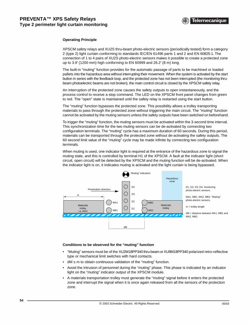
PREVENTA™ XPS Safety RelaysType 2 perimeter light curtain monitoring
54
XPSCM Safety modules and photo-electric sensors with built-in muting function
Operating Principle
XPSCM safety relays and XU2S thru-beam photo-electric sensors (periodically tested) form a category 2 (type 2) light curtain conforming to standards IEC/EN 61496 parts 1 and 2 and EN 60825-1. The connection of 1 to 4 pairs of XU2S photo-electric sensors makes it possible to create a protected zone up to 3.9' (1200 mm) high conforming to EN 60999 and 26.2' (8 m) long.
The built-in “muting” function provides for the automatic passage of parts to be machined or loaded pallets into the hazardous area without interrupting their movement. When the system is activated by the start button in series with the feedback loop, and the protected zone has not been interrupted (the monitoring thru-beam photoelectric beams are not broken), the main control circuit is closed by the XPSCM safety relay.
An interruption of the protected zone causes the safety outputs to open instantaneously, and the process control to receive a stop command. The LED on the XPSCM front panel changes from green to red. The “open” state is maintained until the safety relay is restarted using the start button.
The “muting” function bypasses the protected zone. This possibility allows a trolley transporting materials to pass through the protected zone without triggering the main circuit. The “muting” function cannot be activated by the muting sensors unless the safety outputs have been switched on beforehand.
To trigger the “muting” function, the muting sensors must be activated within the 3-second time interval. This synchronization time for the two muting sensors can be de-activated by connecting two configuration terminals. The “muting” cycle has a maximum duration of 60 seconds. During this period, materials can be transported through the protected zone without de-activating the safety outputs. The 60 second limit value of the “muting” cycle may be made infinite by connecting two configuration terminals.
When muting is used, one indicator light is required at the entrance of the hazardous zone to signal the muting state, and this is controlled by terminal H1 of the XPSCM. A fault at the indicator light (short circuit, open circuit) will be detected by the XPSCM and the muting function will be de-activated. When the indicator light is on, it indicates muting is activated and the light curtain is being bypassed.
D1, D2, D3, D4: monitoring photo-electric sensors.
MA1, MB1, MA2, MB2: “Muting” photo-electric sensors.
m = trolley length
dM = distance between MA1, MB1 and MA2, MB2.
Conditions to be observed for the “muting” function
• “Muting” sensors must be of the XU2M18PP340 thru-beam or XU9M18PP340 polarized retro-reflective type or mechanical limit switches with hard contacts.
• dM ≤ m to obtain continuous validation of the “muting” function.
• Avoid the intrusion of personnel during the “muting” phase. This phase is indicated by an indicator light on the “muting” indicator output of the XPSCM module.
• A materials transportation trolley must generate the “muting” signal before it enters the protected zone and interrupt the signal when it is once again released from all the sensors of the protection zone.
m
dM
MB1
MA1
D4
D2
D3
D1MA2
MB2
Penetration direction
“Muting” indication
Hazardous zone
Materialstrolley
Materialstrolley
i.e.:AGV
© 2003 Schneider Electric All Rights Reserved 05/03
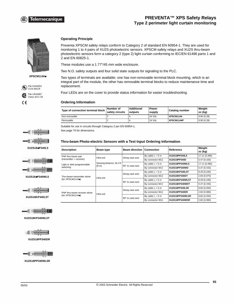
PREVENTA™ XPS Safety RelaysType 2 perimeter light curtain monitoring
05/03
®
File E164353CCN NKCR
File LR44087Class 3211 03
XPSCM1144p
XU2S18pP340L5
XU2S18pP340WL5
XU2S18KP340L5T
XU2S18KP340WL5T
XU2S18PP340DR
XU2S18PP340WL5R
XPSCM Safety modules and photo-electric sensors with built-in muting function
Operating Principle
Preventa XPSCM safety relays conform to Category 2 of standard EN 60954-1. They are used for monitoring 1 to 4 pairs of XU2S photoelectric sensors. XPSCM safety relays and XU2S thru-beam photoelectric sensors form a category 2 (type 2) light curtain conforming to IEC/EN 61496 parts 1 and 2 and EN 60825-1.
These modules use a 1.77"/45 mm wide enclosure.
Two N.O. safety outputs and four solid state outputs for signaling to the PLC.
Two types of terminals are available: one has non-removable terminal block mounting, which is an integral part of the module, the other has removable terminal blocks to reduce maintenance time and replacement.
Four LEDs are on the cover to provide status information for easier troubleshooting.
Suitable for use in circuits through Category 2 per EN 60954-1.
See page 70 for dimensions.
Ordering Information
Type of connection terminal blockNumber of safety circuits
Additional outputs
Power supply
Catalog numberWeightoz (kg)
Non-removable 2 4 24 Vdc XPSCM1144 9.90 (0.28)
Removable 2 4 24 Vdc XPSCM1144P 9.90 (0.28)
Thru-beam Photo-electric Sensors with a Test Input Ordering Information
Description Beam type Beam direction Connection ReferenceWeightoz (kg)
PNP thru-beam pair (transmitter + receiver)
Light or dark programmable switching
Infra-red
Sensing distance: 26.2 ft (8 m)
Along case axisBy cable L = 5 m XU2S18PP340L5 17.11 (0.485)
By connector M12 XU2S18PP340D 5.47 (0.155)
90° to case axisBy cable L = 5 m XU2S18PP340WL5 17.11 (0.485)
By connector M12 XU2S18PP340WD 5.47 (0.155)
Thru-beam transmitter alone(for XPSCM1144p)
Infra-red
Along case axisBy cable L = 5 m XU2S18KP340L5T 8.29 (0.235)
By connector M12 XU2S18KP340DT 2.65 (0.075)
90° to case axisBy cable L = 5 m XU2S18KP340WL5T 8.29 (0.235)
By connector M12 XU2S18KP340WDT 5.47 (0.155)
PNP thru-beam receiver alone(for XPSCM1144p)
Infra-red
Along case axisBy cable L = 5 m XU2S18PP340L5R 8.82 (0.250)
By connector M12 XU2S18PP340DR 2.82 (0.080)
90° to case axisBy cable L = 5 m XU2S18PP340WL5R 8.82 (0.250)
By connector M12 XU2S18PP340WDR 2.82 (0.080)
55© 2003 Schneider Electric All Rights Reserved
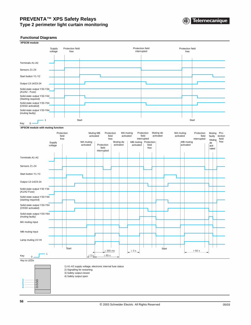
PREVENTA™ XPS Safety RelaysType 2 perimeter light curtain monitoring
56
Functional Diagrams XPSCM module
XPSCM module with muting funct
Key to LEDs
1 0
Supplyvoltage
Key
Terminals A1-A2
Sensors Z1-Z4
Start button Y1-Y2
Output 13-14/23-24
Solid-state output Y33-Y34 (A1/A2 - Fuse)
Solid-state output Y33-Y64(muting faulty)
Solid-state output Y33-Y44(Starting required)
Solid-state output Y33-Y54(OSSD activated)
1 0Key
Terminals A1-A2
Sensors Z1-Z4
Start button Y1-Y2
Output 13-14/23-24
Solid-state output Y33-Y54(OSSD activated)
Supplyvoltage
Pro
Solid-state output Y33 Y34(A1/A2 Fuse)
Solid-state output Y33-Y44(starting required)
Solid-state output Y33-Y64(muting faulty)
MA muting input
MB muting input
Lamp muting UV-HI
1234
XPSCM Safety modules and photo-electric sensors with built-in muting function
ion
1) A1-A2 supply voltage, electronic internal fuse status2) Signalling for restarting3) Safety output closed4) Safety output open
Protection field free
Protection field interrupted
Protection field free
Start Start
≤ 3 s
≥ 3 s
≤ 60 s
> 60 s≥ 300 ms
tection field free
MA muting activated
Muting MB activated
Protection field
interrupted
Protection field free
Muting de-activated
MA muting activated
MB mutingactivated
Protection field
interruptedProtection
fieldfree
Muting de-activated
Protectionfield
interrupted
MA muting activated
MB muting activated
Muting faulty
Muting de acti-vated
Pro-tection
field free
Start Start
© 2003 Schneider Electric All Rights Reserved 05/03
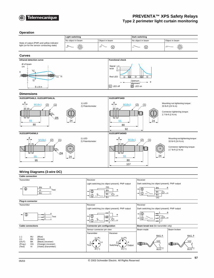
PREVENTA™ XPS Safety RelaysType 2 perimeter light curtain monitoring
05/03
Operation
State of output (PNP) and yellow indlight (on for the sensor conducting st
CurvesInfrared detection curve
DimensionsXU2S18PP340L5, XU2S18PP340L
XU2S18PP340WL5
Wiring Diagrams (3-wirCable connection
Transmitter
Plug-in connector
Transmitter
Cable connections
(–)(+)(OUT)(Prog.)(Test)
BUBNBKOGVI
(Blue)(Brown)(Black) (receiver)(Orange) (receive(Violet) (transmit
Ø of beamcm
E
4
80
55
M18x1 (2)
4M18x1
95
(2)
55
BN
BU
+
–VI T
1
32 T
XPSCM Safety modules and photo-electric sensors with built-in muting function
icator ate)
Light switching Dark switching
No object in beam Object in beam No object in beam Object in beam
Functional check
5L XU2S18PP340D
1) LED2) Potentiometer
Mounting nut tightening torque: 33 lb-ft (24 N.m)
Connector tightening torque: 2.7 lb-ft (2 N.m)
XU2S18PP340WD
1) LED2) Potentiometer
Mounting nut tightening torque: 33 lb-ft (24 N.m)
Connector tightening torque: 2.7 lb-ft (2 N.m)
e DC)
Receiver Receiver
Light switching (no object present). PNP output Dark switching (no object present). PNP output
Receiver Receiver
Light switching (no object present). PNP output Dark switching (no object present). PNP output
Connector pin configuration Beam break test (for transmitter only)
Sensor connector pin view Beam made Beam broken
r)ter)
Transmitter Receiver
11 m
0,711,5
+–
Signal level
Red LED
Optimum alignment
LED off LED on
24
(1)
80
55
92
4
24
(1)M18x1 (2)
(1)
2480
55
107
4(1)M18x1 (2)
24
estOG
BN
BK
BU
+
–
BN
BUOG
BK
+
–
est+
–3
4
1
2 +
–
234
1
+
–
BN/1
VI/2
BU/3
+
–
BN/1
VI/2
BU/3
1 (+)
3 (–)
42Test
1 (+)
3 (–)
42Switching Output
57© 2003 Schneider Electric All Rights Reserved
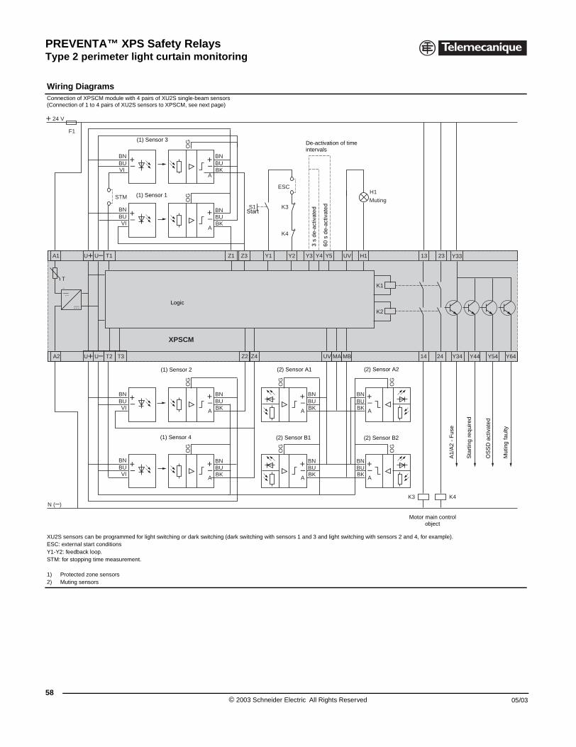
PREVENTA™ XPS Safety RelaysType 2 perimeter light curtain monitoring
58
Wiring Diagrams Connection of XPSCM module with (Connection of 1 to 4 pairs of XU2S
XU2S sensors can be programmed ESC: external start conditions Y1-Y2: feedback loop.STM: for stopping time measuremen
1) Protected zone sensors2) Muting sensors
T1A1 U U
T2U U T3A2
24 V
N ( )
F1
BNBUVI
BNBUVI
STM
BNBUVI
BNBUVI
T
XPSCM Safety modules and photo-electric sensors with built-in muting function
4 pairs of XU2S single-beam sensorssensors to XPSCM, see next page)
for light switching or dark switching (dark switching with sensors 1 and 3 and light switching with sensors 2 and 4, for example).
t.
Z4 UV MA MBZ2
Y2
Y342414
H1UVZ1 Z3
XPSCM
Y33Y1 Y4 Y5Y3
K1
BNBUBK
OG
OG
BNBUBK
K2
K3 K4
2313
Y64Y54
H1
S1 K3
K4
A
A
A
A
BNBUBK
OG
OG
BNBUBK
Y44
ESC
Muting
A
A
BNBUBK
OG
OG
OG
OG
BNBUBK
BNBUBK
BNBUBK
A
A
(1) Sensor 3
(1) Sensor 1
Start
De-activation of time intervals
3 s
de-a
ctiv
ated
60 s
de-
activ
ated
Logic
A1/
A2
- F
use
(1) Sensor 2
(1) Sensor 4
(2) Sensor A1
(2) Sensor B1 (2) Sensor B2
(2) Sensor A2
Sta
rtin
g re
quire
d
Mut
ing
faul
ty
OS
SD
act
ivat
ed
Motor main control object
© 2003 Schneider Electric All Rights Reserved 05/03
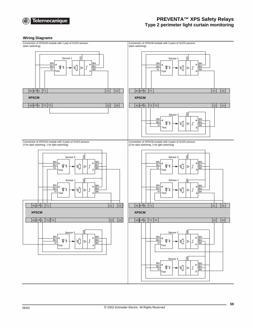
PREVENTA™ XPS Safety RelaysType 2 perimeter light curtain monitoring
05/03
Wiring Diagrams Connection of XPSCM module with (dark switching)
Connection of XPSCM module with (2 for dark switching, 1 for light switc
T1A1 U+ U
T2U+ U T3A2
XPSCM
BNBUVI
+
S
Test
T1A1 U+ U
T2U+ U T3A2
XPSCM
BNBUVI
BNBUVI
+
+
+
BNBUVI
Test
Test
Tes
XPSCM Safety modules and photo-electric sensors with built-in muting function
1 pair of XU2S sensors Connection of XPSCM module with 2 pairs of XU2S sensors(dark switching)
3 pairs of XU2S sensorshing)
Connection of XPSCM module with 4 pairs of XU2S sensors(2 for dark switching, 2 for light switching)
Z4Z2
Z1 Z3
BNBUBK
OG
+
A
ensor 1
T1A1 U+ U
T2U+ U T3A2 Z4Z2
Z1 Z3
XPSCM
BNBUBK
BN
OG
BUVI
+
+ +
A
BNBUBK
BN
OG
BUVI
+
A
Sensor 1
Test
Sensor 2
Test
Z4Z2
Z1 Z3
BNBUBK
OG
OG
BNBUBK
+
+
A
A
BNBUBK
OG
+
A
Sensor 3
Sensor 2
Sensor 1
t
T1A1 U+ U
T2U+ U T3A2 Z4Z2
Z1 Z3
XPSCM
BNBUBK
BN
OG
OG
BUVI
BNBUVI
BNBUBK
+
+
+
+
A
A
BNBUBK
BN
OG
OG
BUVI
BNBUVI
BNBUBK
++
+
A
+
A
Sensor 3
Test
Sensor 2
Test
Sensor 1
Test
Sensor 4
Test
59© 2003 Schneider Electric All Rights Reserved
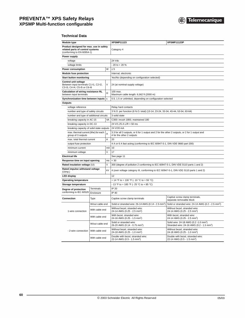
PREVENTA™ XPS Safety RelaysXPSMP Multi-function configurable
60
XPSMP Safety Relays
Technical Data
Module type XPSMP11123 XPSMP11123P
Product designed for max. use in safety related parts of control systems (conforming to EN 60954-1)
Category 4
Power supply
voltage 24 Vdc
voltage limits - 20 to + 20 %
Power consumption W ≤ 5
Module fuse protection Internal, electronic
Start button monitoring Yes/No (depending on configuration selected)
Control unit voltageBetween input terminals C1-I1, C2-I2,C3-I3, C4-I4, C5-I5 or C6-I6
V 24 (at nominal supply voltage)
Calculation of wiring resistance RLbetween input terminals
Ω 100 max.Maximum cable length: 6,562 ft (2000 m)
Synchronization time between inputs s 0.5, 1.5 or unlimited, depending on configuration selected
Outputs
voltage reference Relay hard contacts
number and type of safety circuits 3 N.O. per function (6 N.O. total) (13-14, 23-24, 33-34, 43-44, 53-54, 63-64)
number and type of additional circuits 3 solid state
breaking capacity in AC-15 VA C300: inrush 1800, maintained 180
breaking capacity in DC-13 24 V/1.25 A L/R = 50 ms
breaking capacity of solid state outputs 24 V/20 mA
max. thermal current (Ithe) for each group of 3 outputs
A3.3 for all 3 outputs, or 6 for 1 output and 2 for the other 2 outputs, or 2 for 1 output and 4 for the other 2 outputs
max. total thermal current A 20
output fuse protection 4 A or 6 A fast acting (conforming to IEC 60947-5-1, DIN VDE 0660 part 200)
minimum current mA 10
minimum voltage V 17
Electrical life See page 11
Response time on input opening ms < 30
Rated insulation voltage (Ui) V 300 (degree of pollution 2 conforming to IEC 60947-5-1, DIN VDE 0110 parts 1 and 2)
Rated impulse withstand voltage (Uimp.)
kV 4 (over voltage category III, conforming to IEC 60947-5-1, DIN VDE 0110 parts 1 and 2)
LED display 12
Operating temperature + 14 °F to + 130 °F (- 10 °C to + 55 °C)
Storage temperature - 13 °F to + 185 °F (- 25 °C to + 85 °C)
Degree of protectionconforming to IEC 60529
Terminals IP 20
Enclosure IP 40
Connection Type Captive screw clamp terminalsCaptive screw clamp terminals, separate removable block
1-wire connection
W/out cable end Solid or stranded wire: 26-14 AWG (0.14 - 2.5 mm2) Solid or stranded wire: 24-14 AWG (0.2 - 2.5 mm2)
With cable endWithout bezel, stranded wire: 24-14 AWG (0.25 - 2.5 mm2)
Without bezel, stranded wire: 24-14 AWG (0.25 - 2.5 mm2)
With cable endWith bezel, stranded wire: 24-16 AWG (0.25 - 1.5 mm2)
With bezel, stranded wire:24-14 AWG (0.25 - 2.5 mm2)
- 2-wire connection
W/out cable endSolid or stranded wire: 26-20 AWG (0.14 - 0.75 mm2)
Solid wire: 24-18 AWG (0.2 -1.0 mm2)Stranded wire: 24-16 AWG (0.2 - 1.5 mm2)
With cable endWithout bezel, stranded wire: 24-18 AWG (0.25 - 1.0 mm2)
Without bezel, stranded wire: 24-18 AWG (0.25 - 1.0 mm2)
With cable endDouble with bezel, stranded wire: 22-14 AWG (0.5 - 1.5 mm2)
Double with bezel, stranded wire: 22-14 AWG (0.5 - 1.5 mm2)
© 2003 Schneider Electric All Rights Reserved 05/03
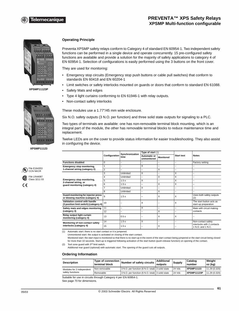
PREVENTA™ XPS Safety RelaysXPSMP Multi-function configurable
05/03
®
File E164353CCN NKCR
File LR44087Class 3211 03
XPSMP11123P
XPSMP11123
XPSMP Safety Relays
Operating Principle
Preventa XPSMP safety relays conform to Category 4 of standard EN 60954-1. Two independent safety functions can be performed in a single device and operate concurrently. 15 pre-configured safety functions are available and provide a solution for the majority of safety applications to category 4 of EN 60954-1. Selection of configurations is easily performed using the 3 buttons on the front cover.
They are used for monitoring:
• Emergency stop circuits (Emergency stop push buttons or cable pull switches) that conform to standards EN 60418 and EN 60204-1
• Limit switches or safety interlocks mounted on guards or doors that conform to standard EN 61088.
• Safety Mats and edges
• Type 4 light curtains conforming to EN 61946-1 with relay outputs.
• Non-contact safety interlocks
These modules use a 1.77"/45 mm wide enclosure.
Six N.O. safety outputs (3 N.O. per function) and three solid state outputs for signaling to a PLC.
Two types of terminals are available: one has non-removable terminal block mounting, which is an integral part of the module, the other has removable terminal blocks to reduce maintenance time and replacement.
Twelve LEDs are on the cover to provide status information for easier troubleshooting. They also assist in configuring the device.
(1) Automatic start: there is no start contact or it is jumpered.Unmonitored start: the output is activated on closing of the start contact.Monitored start: the start input is monitored so that there is no start-up in the event of the start contact being jumpered or the start circuit being closed for more than 10 seconds. Start-up is triggered following activation of the start button (push-release function) on opening of the contact.
(2) Tool zone guard with 3rd limit switch. Additional rear guard (optional) with automatic start. The opening of the guard cuts all outputs.
Suitable for use in circuits through Category 4 per EN 60954-1.See page 70 for dimensions.
Configuration Synchronization time
Type of start (1)Start test NotesAutomatic or
unmonitored Monitored
Functions disabled 0 – – – – Factory setting
Emergency stop monitoring,1-channel wiring (category 2)
1 – X – – –
2 – – X – –
Emergency stop monitoring,2-channel wiring, orguard monitoring (category 4)
3 Unlimited X – X –
4 Unlimited – X X –
5 1.5 s X – X –
6 1.5 s – X X –
7 Unlimited X – – –
8 Unlimited – X – –
Guard monitoring for injector press or blowing machine (category 4)
9 1.5 s – X XUses both safety outputs (2)
Validation control with handle(3 position limit switch) (category 4) 10 – X – X
The start button acts as start-up preparation
Safety mats and edges monitoring (category 3)
11 – X – – Mats with circuit making contacts12 – – X –
Relay output light curtain monitoring (category 4)
13 0.5 s – X X –
Monitoring of non-contact safety interlocks (category 4)
14 1.5 s X – – Non-contact safety interlocks with 2 contacts 1 N.O. and 1 N.C.15 1.5 s – X –
Ordering Information
DescriptionType of connectionterminal block
Number of safety circuitsAdditional outputs
SupplyCatalog number
Weightoz (kg)
Modules for 2 independentsafety functions
Non-removable 3 N.O. per function (6 N.O. total) 3 solid state 24 Vdc XPSMP11123 11.29 (0.320)
Removable 3 N.O. per function (6 N.O. total) 3 solid state 24 Vdc XPSMP11123P 11.29 (0.320)
61© 2003 Schneider Electric All Rights Reserved
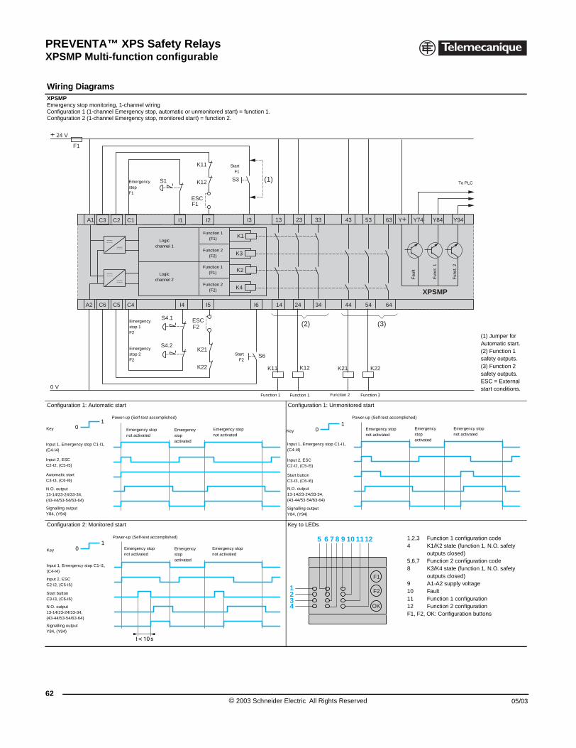
PREVENTA™ XPS Safety RelaysXPSMP Multi-function configurable
62
Wiring Diagrams XPSMPEmergency stop monitoring, 1-chanConfiguration 1 (1-channel EmergenConfiguration 2 (1-channel Emergen
Configuration 1: Automatic start
Configuration 2: Monitored start
F1
+ 24 V
0 V
A1
A2 C4C5C6
C1C2C3
EmestopF1
EmestopF2
EmestopF2
Input 1, Emergency stop C1-I1, (C4-I4)
Input 2, ESCC2-I2, (C5-I5)
Automatic startC3-I3, (C6-I6)
N.O. output13-14/23-24/33-34,(43-44/53-54/63-64)
Signalling outputY84, (Y94)
Emernot ac
Power-up (Se
01
Key
Input 1, Emergency stop C1-I1, (C4-I4)
Input 2, ESCC2-I2, (C5-I5)
Start buttonC3-I3, (C6-I6)
N.O. output13-14/23-24/33-34,(43-44/53-54/63-64)
Signalling outputY84, (Y94)
Emergnot act
Power-up (S
01
Key
XPSMP Safety Relays
nel wiringcy stop, automatic or unmonitored start) = function 1.cy stop, monitored start) = function 2.
(1) Jumper for Automatic start.(2) Function 1 safety outputs.(3) Function 2 safety outputs.ESC = External start conditions.
Configuration 1: Unmonitored start
Key to LEDs
1,2,3 Function 1 configuration code4 K1/K2 state (function 1, N.O. safety
outputs closed)5,6,7 Function 2 configuration code8 K3/K4 state (function 1, N.O. safety
outputs closed)9 A1-A2 supply voltage10 Fault11 Function 1 configuration12 Function 2 configuration F1, F2, OK: Configuration buttons
K2
K4
23
XPSMP
I4 14 24
13
K12K11 K22K21
I3
S3
ESC
S1
ESCS4.1
S4.2
K11
K12
F1
F2
K21
K22
I6I5
I1 I2
K1
K3
43
44
53
54
33
34
63
64
Y74Y+ Y94Y84
(2)
(1)
(3)
S6
Logicchannel 1
Logicchannel 2
StartF2
rgency
Fau
lt
rgency 1
Function 1(F1)
Function 2(F2)
Function 1(F1)
Function 2(F2)
Fun
ct. 1
Fun
ct. 2
To PLC
rgency 2
StartF1
Function 1 Function 1 Function 2 Function 2
Emergency stopnot activated
Emergency stopactivated
gency stoptivated
lf-test accomplished)
Input 1, Emergency stop C1-I1, (C4-I4)
Input 2, ESCC2-I2, (C5-I5)
Start buttonC3-I3, (C6-I6)
N.O. output13-14/23-24/33-34,(43-44/53-54/63-64)
Signalling outputY84, (Y94)
Emergency stopnot activated
Emergency stopactivated
Emergency stopnot activated
Power-up (Self-test accomplished)
01
Key
Emergency stopnot activated
Emergency stopactivated
ency stopivated
elf-test accomplished)
1
5 6 7 8 9 10 1112
234
F1
F2
OK
© 2003 Schneider Electric All Rights Reserved 05/03
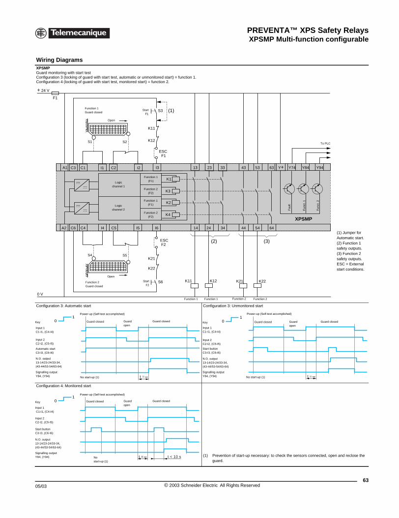
PREVENTA™ XPS Safety RelaysXPSMP Multi-function configurable
05/03
Wiring Diagrams XPSMPGuard monitoring with start testConfiguration 3 (locking of guard witConfiguration 4 (locking of guard wit
Configuration 3: Automatic start
Configuration 4: Monitored start
F1
+ 24 V
0 V
A1
A2 C4C6
C1C3
S4
S1
Function 1Guard clos
Function 2Guard clo
Input 1 C1-I1, (C4-I4)
Input 2C2-I2, (C5-I5)
Automatic startC3-I3, (C6-I6)
N.O. output13-14/23-24/33-34,(43-44/53-54/63-64)
Signalling outputY84, (Y94)
Guard clo
Power-up (Sel
No start-up (1
01
Key
Input 1 C1-I1, (C4-I4)
Input 2C2-I2, (C5-I5)
Start buttonC3-I3, (C6-I6)
N.O. output13-14/23-24/33-34,(43-44/53-54/63-64)
Signalling outputY84, (Y94)
Guard clo
Power-up (Sel
Nostar
01
Key
XPSMP Safety Relays
h start test, automatic or unmonitored start) = function 1.h start test, monitored start) = function 2.
(1) Jumper for Automatic start.(2) Function 1 safety outputs.(3) Function 2 safety outputs.ESC = External start conditions.
Configuration 3: Unmonitored start
(1) Prevention of start-up necessary: to check the sensors connected, open and reclose the guard.
K2
K4
23
XPSMP
I4 C5 14 24
13
K12K11 K22K21
I3
ESC
ESC
K11
K12
F1
F2
K21
K22
I6I5
I1 C2 I2
K1
K3
43
44
53
54
33
34
63
64
Y74Y+ Y94Y84
(2) (3)
S6
S5
S2
S3 (1)
Logicchannel 1
Logicchannel 2
StartF2
ed
Fau
lt
Function 1(F1)
Function 2(F2)
Function 1(F1)
Function 2(F2)
Fun
ct. 1
Fun
ct. 2
To PLC
sed
StartF1
Open
Open
Function 1 Function 1 Function 2 Function 2
t =
Guard closedGuardopen
sed
f-test accomplished)
) t =
Input 1 C1-I1, (C4-I4)
Input 2C2-I2, (C5-I5)
Start buttonC3-I3, (C6-I6)
N.O. output13-14/23-24/33-34,(43-44/53-54/63-64)
Signalling outputY84, (Y94)
Guard closedGuardopen
Guard closed
Power-up (Self-test accomplished)
No start-up (1)
01
Key
t = t < 10 s
Guard closedGuardopen
sed
f-test accomplished)
t-up (1)
63© 2003 Schneider Electric All Rights Reserved
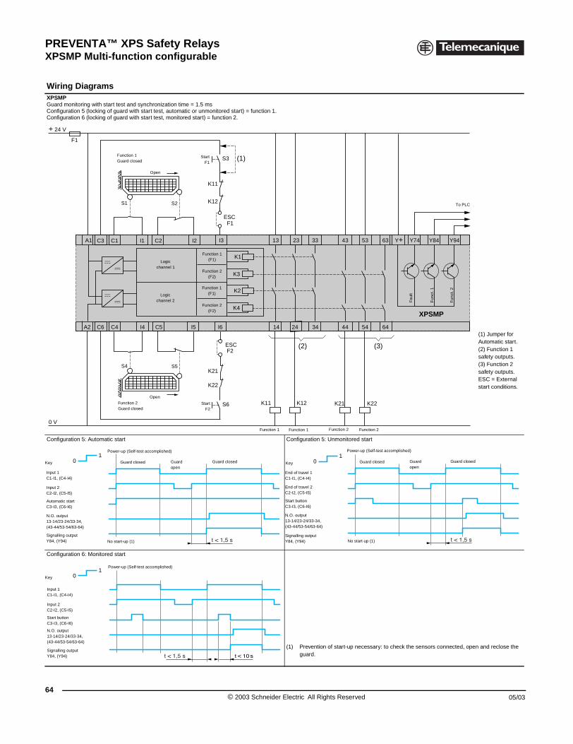
PREVENTA™ XPS Safety RelaysXPSMP Multi-function configurable
64
Wiring Diagrams XPSMPGuard monitoring with start test andConfiguration 5 (locking of guard witConfiguration 6 (locking of guard wit
Configuration 5: Automatic start
Configuration 6: Monitored start
F1
+ 24 V
0 V
A1
A2 C4C6
C1C3
S4
S1
Function 1Guard clo
Function Guard clo
01
Key
Input 1 C1-I1, (C4-I4)
Input 2C2-I2, (C5-I5)
Automatic startC3-I3, (C6-I6)
N.O. output13-14/23-24/33-34,(43-44/53-54/63-64)
Signalling outputY84, (Y94)
Guard c
Power-up (Self
No start-up (1)
01
Key
Input 1C1-I1, (C4-I4)
Input 2C2-I2, (C5-I5)
Start buttonC3-I3, (C6-I6)
N.O. output13-14/23-24/33-34,(43-44/53-54/63-64)
Signalling outputY84, (Y94)
Guard clo
Power-up (Self
XPSMP Safety Relays
synchronization time = 1.5 msh start test, automatic or unmonitored start) = function 1.h start test, monitored start) = function 2.
(1) Jumper for Automatic start.(2) Function 1 safety outputs.(3) Function 2 safety outputs.ESC = External start conditions.
Configuration 5: Unmonitored start
(1) Prevention of start-up necessary: to check the sensors connected, open and reclose the guard.
K2
K4
23
XPSMP
I4 C5 14 24
13
K12K11 K22K21
I3
ESC
ESC
K11
K12
F1
F2
K21
K22
I6I5
I1 C2 I2
K1
K3
43
44
53
54
33
34
63
64
Y74Y+ Y94Y84
(2) (3)
S6
S5
S2
S3 (1)
Logicchannel 1
Logicchannel 2
StartF2
sed
Fau
lt
Function 1(F1)
Function 2(F2)
Function 1(F1)
Function 2(F2)
Fun
ct. 1
Fun
ct. 2
To PLC
2sed
StartF1
Open
Open
Function 1 Function 1 Function 2 Function 2
Guard closedGuardopen
losed
-test accomplished)
01
Key
End of travel 1C1-I1, (C4-I4)
End of travel 2C2-I2, (C5-I5)
Start buttonC3-I3, (C6-I6)
N.O. output13-14/23-24/33-34,(43-44/53-54/63-64)
Signalling outputY84, (Y94)
Guard closedGuardopen
Guard closed
Power-up (Self-test accomplished)
No start-up (1)
Guard closedGuardopen
sed
-test accomplished)
© 2003 Schneider Electric All Rights Reserved 05/03
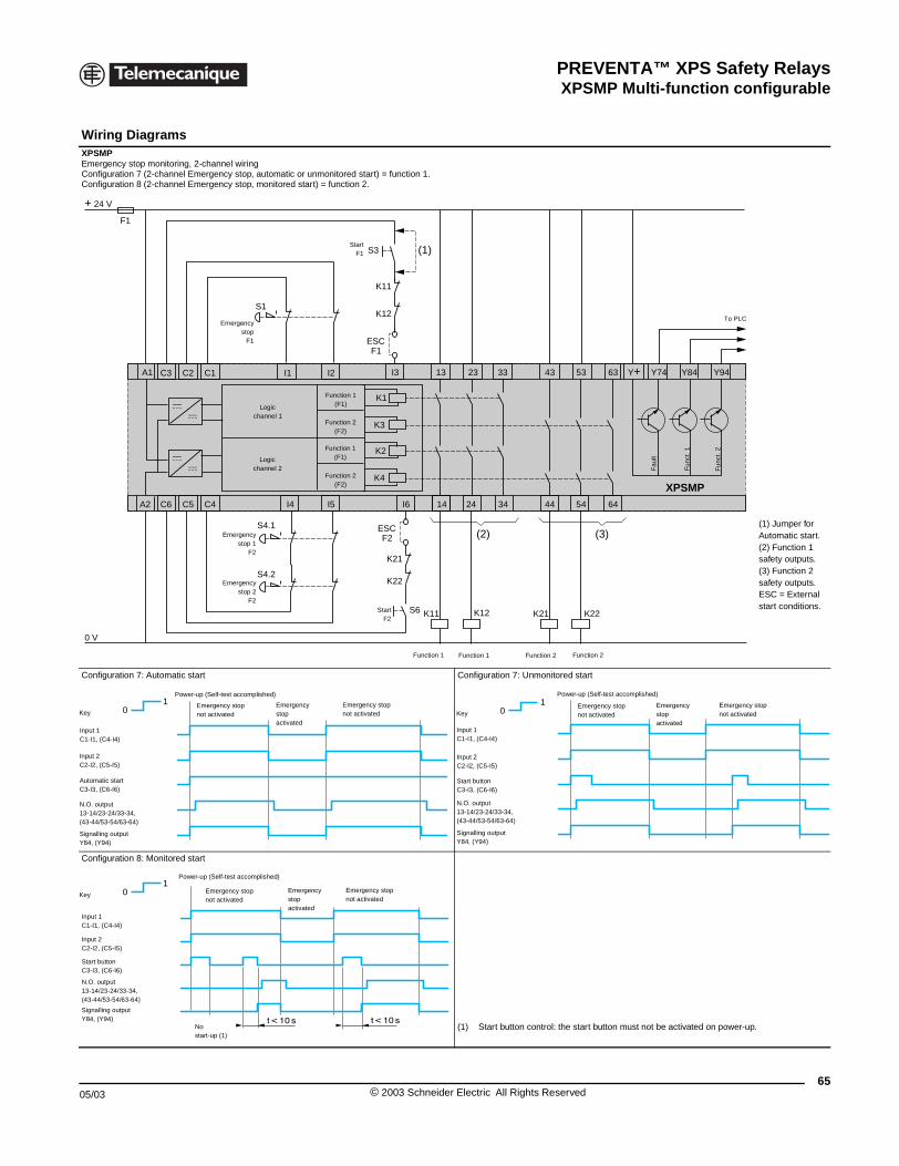
PREVENTA™ XPS Safety RelaysXPSMP Multi-function configurable
05/03
Wiring Diagrams XPSMPEmergency stop monitoring, 2-chanConfiguration 7 (2-channel EmergenConfiguration 8 (2-channel Emergen
Configuration 7: Automatic start
Configuration 8: Monitored start
F1
+ 24 V
0 V
A1
A2 C4C5C6
C1C2C3
E
01
Key
Input 1 C1-I1, (C4-I4)
Input 2C2-I2, (C5-I5)
Automatic startC3-I3, (C6-I6)
N.O. output13-14/23-24/33-34,(43-44/53-54/63-64)
Signalling outputY84, (Y94)
Power-up (Self-t
Emergennot activ
01
Key
Input 1C1-I1, (C4-I4)
Input 2C2-I2, (C5-I5)
Start buttonC3-I3, (C6-I6)
N.O. output13-14/23-24/33-34,(43-44/53-54/63-64)
Signalling outputY84, (Y94)
Power-up (Self
Nostart-up (
Emernot ac
XPSMP Safety Relays
nel wiringcy stop, automatic or unmonitored start) = function 1.cy stop, monitored start) = function 2.
(1) Jumper for Automatic start.(2) Function 1 safety outputs.(3) Function 2 safety outputs.ESC = External start conditions.
Configuration 7: Unmonitored start
(1) Start button control: the start button must not be activated on power-up.
K2
K4
23
XPSMPI4 14 24
13
K12K11 K22K21
I3
S3
ESC
S1
S4.1
S4.2
K11
K12
F1
ESCF2
K21
K22
I6I5
I1 I2
K1
K3
43
44
53
54
33
34
63
64
Y74Y+ Y94Y84
(2)
(1)
(3)
S6
Logicchannel 1
Logicchannel 2 F
ault
Function 1(F1)
Function 2(F2)
Function 1(F1)
Function 2(F2)
Fun
ct. 1
Fun
ct. 2
To PLC
StartF1
Function 1 Function 1 Function 2 Function 2
Emergencystop 2
F2
mergencystop
F1
StartF2
Emergencystop 1
F2
est accomplished)
Emergency stopnot activated
Emergency stopactivated
cy stopated 0
1Key
Input 1C1-I1, (C4-I4)
Input 2C2-I2, (C5-I5)
Start buttonC3-I3, (C6-I6)
N.O. output13-14/23-24/33-34,(43-44/53-54/63-64)
Signalling outputY84, (Y94)
Power-up (Self-test accomplished)
Emergency stopnot activated
Emergency stopactivated
Emergency stopnot activated
-test accomplished)
1)
Emergency stopnot activated
Emergency stopactivated
gency stoptivated
65© 2003 Schneider Electric All Rights Reserved
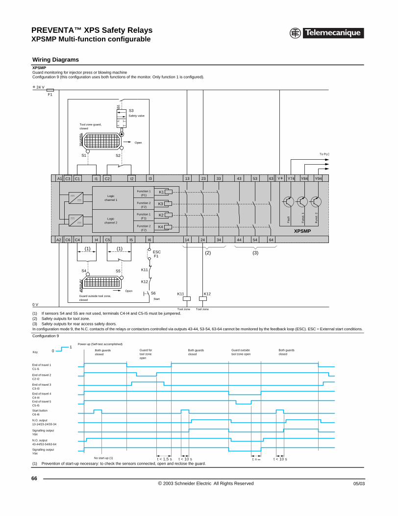
PREVENTA™ XPS Safety RelaysXPSMP Multi-function configurable
66
Wiring Diagrams XPSMPGuard monitoring for injector press oConfiguration 9 (this configuration u
(1) If sensors S4 and S5 are not u(2) Safety outputs for tool zone.(3) Safety outputs for rear access In configuration mode 9, the N.C. con
Configuration 9
(1) Prevention of start-up necessa
F1
+ 24 V
0 V
A1
A2 C4C6
C1C3
(1)
S4
S1
Tool zone gclosed
Guard outsiclosed
01
Key
End of travel 1C1-I1
End of travel 2C2-I2
Start buttonC6-I6
N.O. output13-14/23-24/33-34
Signalling outputY94
Power-up (S
Signalling outputY84
N.O. output43-44/53-54/63-64
End of travel 3C3-I3
End of travel 4C4-I4End of travel 5C5-I5
XPSMP Safety Relays
r blowing machineses both functions of the monitor. Only function 1 is configured).
sed, terminals C4-I4 and C5-I5 must be jumpered.
safety doors. tacts of the relays or contactors controlled via outputs 43-44, 53-54, 63-64 cannot be monitored by the feedback loop (ESC). ESC = External start conditions.
ry: to check the sensors connected, open and reclose the guard.
K2
K4
23
XPSMP
I4 C5 14 24
13
K12K11
I3
ESCF1
K11
K12
I6I5
I1 C2 I2
K1
K3
43
44
53
54
33
34
63
64
Y74Y+ Y94Y84
(2)(1)
(3)
S6
S5
S3
S2
Logicchannel 1
Logicchannel 2
Start
Fau
lt
Function 1(F1)
Function 2(F2)
Function 1(F1)
Function 2(F2)
Fun
ct. 1
Fun
ct. 2
To PLC
Safety valve
Open
Open
uard,
de tool zone,
Tool zone Tool zone
t < 1,5 s t < 10 s t = t < 10 s
Both guards closed
elf-test accomplished)
No start-up (1)
Guard fortool zoneopen
Guard outsidetool zone open
Both guards closed
Both guards closed
© 2003 Schneider Electric All Rights Reserved 05/03
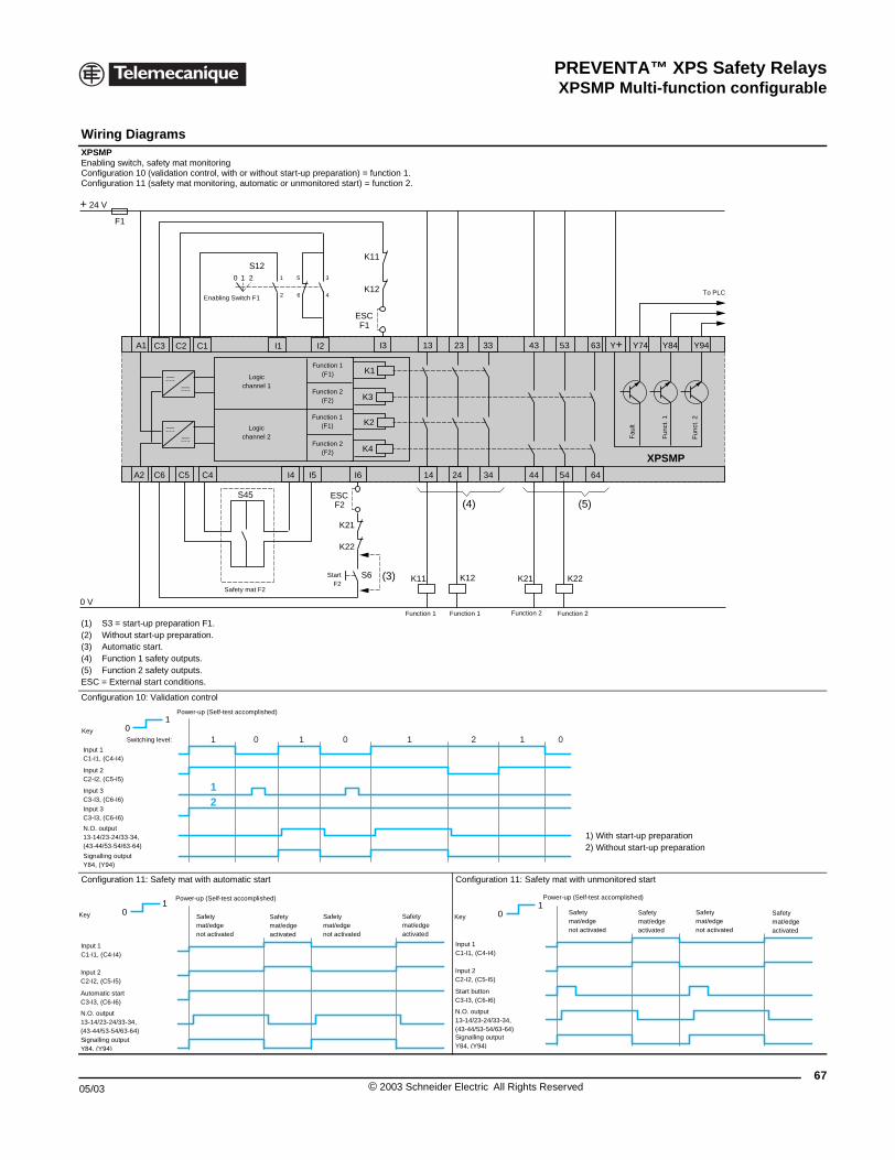
PREVENTA™ XPS Safety RelaysXPSMP Multi-function configurable
05/03
Wiring Diagrams XPSMPEnabling switch, safety mat monitoriConfiguration 10 (validation control, Configuration 11 (safety mat monito
(1) S3 = start-up preparation F1.(2) Without start-up preparation.(3) Automatic start.(4) Function 1 safety outputs.(5) Function 2 safety outputs.ESC = External start conditions.
Configuration 10: Validation control
Configuration 11: Safety mat with au
F1
+ 24 V
0 V
A1
A2 C4C5C6
C1C2C3
Enabl
01
Key1
12
Input 1 C1-I1, (C4-I4)
Input 2C2-I2, (C5-I5)
Input 3C3-I3, (C6-I6)
N.O. output13-14/23-24/33-34,(43-44/53-54/63-64)
Signalling outputY84, (Y94)
Power-up (Self
Input 3C3-I3, (C6-I6)
Switching level:
01
Key
Input 1C1-I1, (C4-I4)
Input 2C2-I2, (C5-I5)
Automatic startC3-I3, (C6-I6)
N.O. output13-14/23-24/33-34,(43-44/53-54/63-64)Signalling outputY84, (Y94)
Power-up (Self-
Safetymat/edgnot activ
XPSMP Safety Relays
ngwith or without start-up preparation) = function 1.ring, automatic or unmonitored start) = function 2.
1) With start-up preparation2) Without start-up preparation
tomatic start Configuration 11: Safety mat with unmonitored start
K2
K4
23
XPSMP
I4 14 24
13
K12K11 K22K21
I3
ESC
S120 1 2 1
2
5
6
3
4
K11
K12
F1
ESCF2
K21
K22
I6I5
I1 I2
K1
K3
43
44
53
54
33
34
63
64
Y74Y+ Y94Y84
(4) (5)
(3)S6XY2-TP
S45
Logicchannel 1
Logicchannel 2
StartF2
Fau
lt
Function 1(F1)
Function 2(F2)
Function 1(F1)
Function 2(F2)
Fun
ct. 1
Fun
ct. 2
To PLC
Safety mat F2
Function 1 Function 1 Function 2 Function 2
ing Switch F1
0 01 1 2 1 0
-test accomplished)
test accomplished)
Safetymat/edgenot activated
Safetymat/edge activated
eated
Safetymat/edgeactivated
01
Key
Input 1C1-I1, (C4-I4)
Input 2C2-I2, (C5-I5)
Start buttonC3-I3, (C6-I6)
N.O. output13-14/23-24/33-34,(43-44/53-54/63-64)Signalling outputY84, (Y94)
Power-up (Self-test accomplished)
Safetymat/edgenot activated
Safetymat/edge activated
Safetymat/edgenot activated
Safetymat/edge activated
67© 2003 Schneider Electric All Rights Reserved
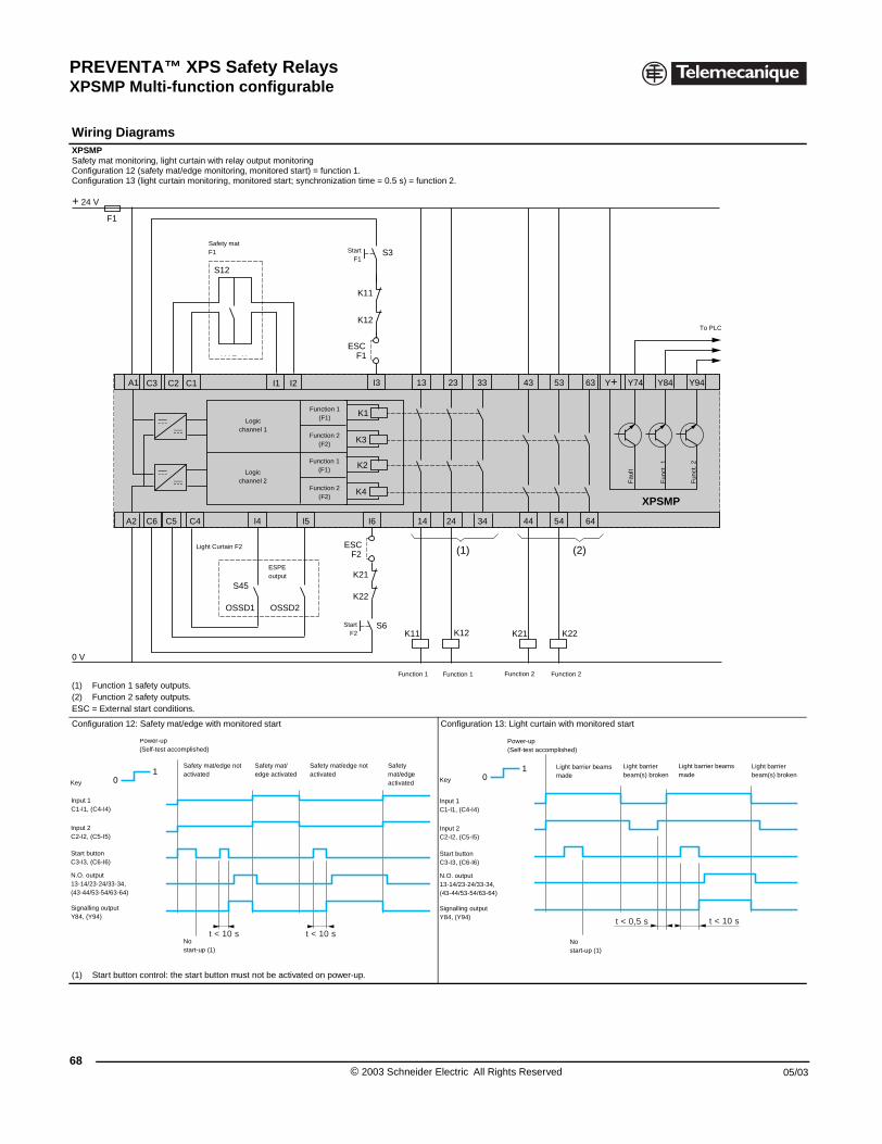
PREVENTA™ XPS Safety RelaysXPSMP Multi-function configurable
68
Wiring Diagrams XPSMPSafety mat monitoring, light curtain wConfiguration 12 (safety mat/edge mConfiguration 13 (light curtain monit
(1) Function 1 safety outputs.(2) Function 2 safety outputs.ESC = External start conditions.
Configuration 12: Safety mat/edge w
(1) Start button control: the start b
F1
+ 24 V
0 V
A1
A2 C4C5C6
C1C2C3
Ligh
01
Key
Input 1 C1-I1, (C4-I4)
Input 2C2-I2, (C5-I5)
Start buttonC3-I3, (C6-I6)
N.O. output13-14/23-24/33-34,(43-44/53-54/63-64)
Signalling outputY84, (Y94)
Safety mactivated
Power-up(Self-test accomplished)
Nostart-up (
XPSMP Safety Relays
ith relay output monitoringonitoring, monitored start) = function 1.
oring, monitored start; synchronization time = 0.5 s) = function 2.
ith monitored start Configuration 13: Light curtain with monitored start
utton must not be activated on power-up.
K2
K4
23
XPSMP
I4 14 24
13
K12K11
S45
S6K22K21
I3
S3
K11
K12
ESCF2
ESCF1
K21
K22
I6I5
I1 I2
K1
K3
43
44
53
54
33
34
63
64
Y74Y+ Y94Y84
(1) (2)
XY2-TP
S12
OSSD1 OSSD2
Logicchannel 1
Logicchannel 2
StartF2
Fau
lt
Function 1(F1)
Function 2(F2)
Function 1(F1)
Function 2(F2)
Fun
ct. 1
Fun
ct. 2
To PLC
t Curtain F2
StartF1
Function 1 Function 1 Function 2 Function 2
ESPEoutput
Safety matF1
t < 10 s t < 10 s
at/edge not
1)
Safety mat/edge activated
Safety mat/edge not activated
Safetymat/edge activated
01
Key
t < 0,5 s t < 10 s
Input 1 C1-I1, (C4-I4)
Input 2C2-I2, (C5-I5)
Start buttonC3-I3, (C6-I6)
N.O. output13-14/23-24/33-34,(43-44/53-54/63-64)
Signalling outputY84, (Y94)
Light barrier beams made
Power-up(Self-test accomplished)
Nostart-up (1)
Light barrier beam(s) broken
Light barrier beams made
Light barrier beam(s) broken
© 2003 Schneider Electric All Rights Reserved 05/03
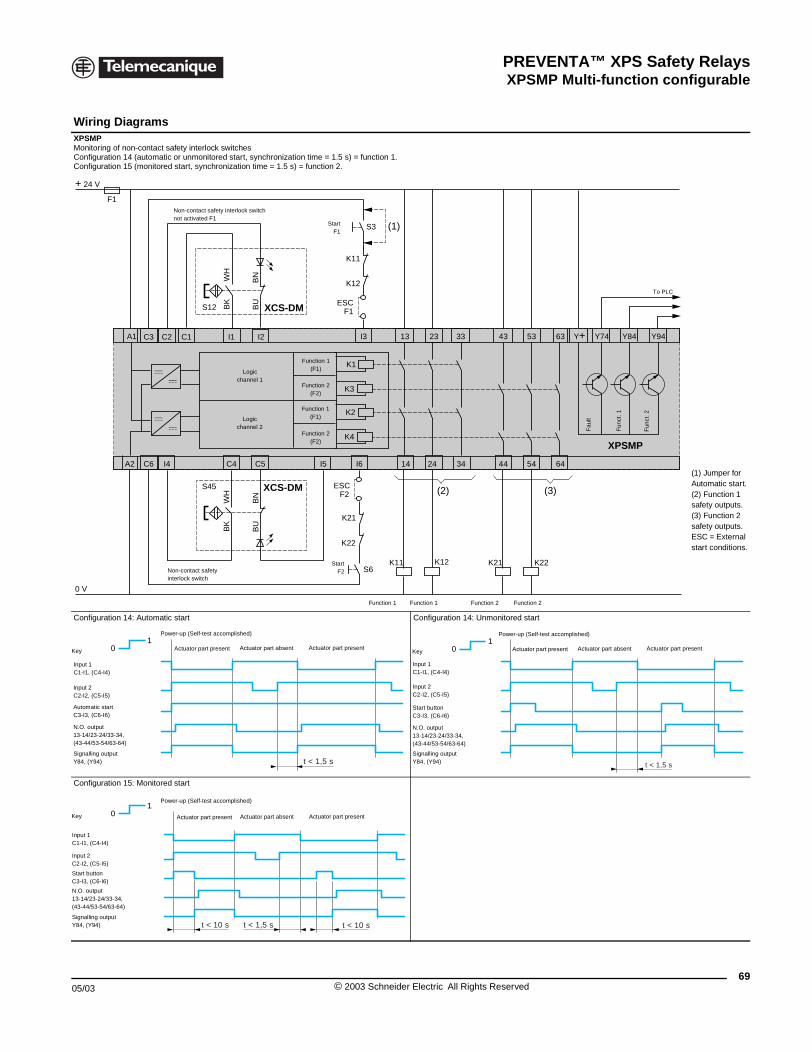
PREVENTA™ XPS Safety RelaysXPSMP Multi-function configurable
05/03
Wiring Diagrams XPSMPMonitoring of non-contact safety inteConfiguration 14 (automatic or unmoConfiguration 15 (monitored start, sy
Configuration 14: Automatic start
Configuration 15: Monitored start
F1
+ 24 V
0 V
A1
A2 I4C6
C1C2C3
Non-contanot activat
Non-contactinterlock swi
01
Key
Input 1 C1-I1, (C4-I4)
Input 2C2-I2, (C5-I5)
Automatic startC3-I3, (C6-I6)
N.O. output13-14/23-24/33-34,(43-44/53-54/63-64)
Signalling outputY84, (Y94)
Power-up (Self
Actuator p
01
Key
Input 1C1-I1, (C4-I4)
Input 2C2-I2, (C5-I5)
Start buttonC3-I3, (C6-I6)
N.O. output13-14/23-24/33-34,(43-44/53-54/63-64)
Signalling outputY84, (Y94)
Power-up (Self
Actuator
XPSMP Safety Relays
rlock switchesnitored start, synchronization time = 1.5 s) = function 1.nchronization time = 1.5 s) = function 2.
(1) Jumper for Automatic start.(2) Function 1 safety outputs.(3) Function 2 safety outputs.ESC = External start conditions.
Configuration 14: Unmonitored start
K2
K4
23
XPSMP
C4 C5 14 24
13
K12K11S6
K22K21
I3
S3
K11
K12
ESCF2
ESCF1
K21
K22
I6I5
I1 I2
K1
K3
43
44
53
54
33
34
63
64
Y74Y+ Y94Y84
(2) (3)
(1)
S12 XCS-DMBK
WH
BU
BN
S45 XCS-DM
BK
WH
BU
BN
Logicchannel 1
Logicchannel 2 F
ault
Function 1(F1)
Function 2(F2)
Function 1(F1)
Function 2(F2)
Fun
ct. 1
Fun
ct. 2
To PLC
StartF1
Function 1 Function 1 Function 2 Function 2
ct safety interlock switched F1
StartF2 safety
tch
t < 1,5 s
-test accomplished)
Actuator part presentActuator part absentart present 01
Key
t < 1,5 s
Input 1C1-I1, (C4-I4)
Input 2C2-I2, (C5-I5)
Start buttonC3-I3, (C6-I6)
N.O. output13-14/23-24/33-34,(43-44/53-54/63-64)
Signalling outputY84, (Y94)
Power-up (Self-test accomplished)
Actuator part presentActuator part absentActuator part present
t < 10 st < 10 s t < 1,5 s
-test accomplished)
Actuator part presentActuator part absentpart present
69© 2003 Schneider Electric All Rights Reserved
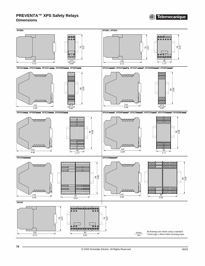
PREVENTA™ XPS Safety RelaysDimensions
70
XPSBA
XPSACpppp, XPSAFpppp, XPSAF
XPSAVpppp, XPSMPpppp, XPSCM
XPSARpppppp
XPSAT
1204.72
1144.49
1144.49
1144.49
1204.72
Dimensions
XPSBC, XPSDA
Lpppp, XPSDMBpppp, XPSBFpppp XPSACppppP, XPSAFpppPp, XPSAFLppppP, XPSDMBppppP, XPSBFppppP
pppp, XPSDMEpppp XPSAVppppP, XPSMPppppP, XPSCMppppP, XPSTSApppP, XPSTSWppppP, XPSDMEpppp
XPSARppppppP
All drawings are shown using a standard 7.5mm high x 35mm DIN3 mounting track.
22.50.89
78 3.07
1204.72
78 3.07
451.77
78 3.07
22.50.89
99 3.90
22.50.89
99 3.90
1144.49
451.77
99 3.90
451.77
99 3.90
1144.49
903.54
99 3.90
903.54
99 3.90
1144.49
903.54
78 3.0778 3.07
inchesmm
© 2003 Schneider Electric All Rights Reserved 05/03
PREVENTA™ XPS Safety Relays
05/03
71© 2003 Schneider Electric All Rights Reserved

Catalog No. 9007CT0203 May 2003 © 2003 Schneider Electric All Rights Reserved
Square D Company8001 Highway 64 EastKnightdale, NC 275451-888-SquareD(1-888-778-2733)www.SquareD.com
Schneider Canada Inc.19 Waterman Avenue, M4B 1 Y2Toronto, Ontario1-800-565-6699www.schneider-electric.ca