Deposition of Ti–6Al–4V using a high power diode laser and wire, Part I: Investigation on the...
8
This article appeared in a journal published by Elsevier. The attached copy is furnished to the author for internal non-commercial research and education use, including for instruction at the authors institution and sharing with colleagues. Other uses, including reproduction and distribution, or selling or licensing copies, or posting to personal, institutional or third party websites are prohibited. In most cases authors are permitted to post their version of the article (e.g. in Word or Tex form) to their personal website or institutional repository. Authors requiring further information regarding Elsevier’s archiving and manuscript policies are encouraged to visit: http://www.elsevier.com/copyright
-
Upload
nottingham -
Category
Documents
-
view
0 -
download
0
Transcript of Deposition of Ti–6Al–4V using a high power diode laser and wire, Part I: Investigation on the...
This article appeared in a journal published by Elsevier. The attachedcopy is furnished to the author for internal non-commercial researchand education use, including for instruction at the authors institution
and sharing with colleagues.
Other uses, including reproduction and distribution, or selling orlicensing copies, or posting to personal, institutional or third party
websites are prohibited.
In most cases authors are permitted to post their version of thearticle (e.g. in Word or Tex form) to their personal website orinstitutional repository. Authors requiring further information
regarding Elsevier’s archiving and manuscript policies areencouraged to visit:
http://www.elsevier.com/copyright

Author's personal copy
Deposition of Ti–6Al–4V using a high power diode laser and wire, Part II:Investigation on the mechanical properties
Sui Him Mok a, Guijun Bi b,⁎, Janet Folkes a, Ian Pashby a, Joel Segal a
a Innovative Manufacturing Processes Group, School of Mechanical, Materials and Manufacturing Engineering, University of Nottingham,University Park, NG7 2RD, UK
b Singapore Institute of Manufacturing Technology, 71 Nanyang Drive, Singapore, 638075
Received 18 October 2007; accepted in revised form 20 March 2008Available online 8 April 2008
Abstract
The deposition with high power diode laser and Ti6Al4V wire was verified as a process which can provide a high deposition rate with goodquality. Sound mechanical properties of the deposited parts are the prerequisites for the real applications of this process. In this paper, the mainmechanical properties including micro-hardness and tensile properties were investigated. Single bead walls were deposited. Test pieces weremachined from the deposited walls according to the British standard for the mechanical tests.
The epitaxial columnar grains were found growing parallel to the building direction. A band region was observed between two depositedlayers, which resulted from the remelting of previously deposited layer and multiple thermal cycles that had occurred with each subsequentdeposition pass. The results showed that with the same laser power, the built samples with higher traverse speed possess similar or slightly higherhardness than the samples built with lower traverse speed. The hardness varied less than 10% with different sets of parameters. The investigationson the tensile properties were carried out with the samples as deposited and stress relieved at 700 °C in an air circulating furnace for 2 h. The asdeposited samples showed better tensile properties than the stress relieved ones. This results from the reduction of the compressive residualstresses and the coarser microstructure after stress relief. The tensile properties also showed dependence on the direction of the test carried out. Allthe examined tensile properties of the as deposited samples matched properties of the as cast and wrought material.© 2008 Elsevier B.V. All rights reserved.
PACS: 81.15.FgKeywords: Deposition; Diode laser; Ti6Al4V; Mechanical properties
1. Introduction
In part I [1] of the present paper, the characteristics of theDirect Diode Laser Deposition (DDLD) with Ti6Al4V wirehave been studied and discussed in detail by deposition of singletracks. A maximum deposition rate of 1 kg/h can be achieved.The deposit showed good dense, free of porosity as well asclean and smooth surface. Front wire feeding with 45° anglewas verified as the best feeding orientation and a maximum wirefeeding rate of 2 m/min was achieved for the setup utilised in thestudy. The results showed that the deposition width is mainlydetermined by laser power. And traverse speed influences theheight more significantly than laser power.
The mechanical properties of the deposited parts are the mainfactors which determine whether the parts are suitable for theapplications or not. The properties must be comparable to thoseof as forged or made by other conventional methods. Thus, themechanical properties of the deposited samples need to beinvestigated. Deposition of Ti6Al4V powder with high powerlasers has been widely investigated by other researchers [2–9].Most of the studies focused on the examination of the phasetransformation and microstructures. Kobryn and Semiatinreported the tensile properties of the stress relieved (700–730 °C/vacuum/2 h) and HIP'ed (900 °C/100 MPa/2 h)Ti6Al4V powder deposits [7]. The stress relieved samplesshowed very low elongation, which resulted from the obviousporosity in the deposits. Kelbassa et al. reported that the stressrelief (640 °C/vacuum/2 h) can increase the elongation of thelaser deposited Ti6Al4V [6]. However, the microstructures of
Available online at www.sciencedirect.com
Surface & Coatings Technology 202 (2008) 4613–4619www.elsevier.com/locate/surfcoat
⁎ Corresponding author. Tel.: +65 67938502.E-mail addresses: [email protected], [email protected] (G. Bi).
0257-8972/$ - see front matter © 2008 Elsevier B.V. All rights reserved.doi:10.1016/j.surfcoat.2008.03.028
Author's personal copy
the as deposited and stress relieved samples were notinvestigated. Furthermore, the mechanical properties of thedeposition with Ti6Al4V wire have not been investigated orreported.
In this paper, the main mechanical properties includinghardness and tensile properties of deposition with wire and highpower diode laser were investigated. Single bead walls weredeposited. Test pieces were machined from the deposited wallsaccording to the British standard for the tensile test. The macro-,microstructure and hardness were analyzed. The yield strength,ultimate tensile strength, Young's module and elongation wereexamined at room temperature 20 °C. These properties wereinvestigated with the as deposited and stress relieved samples.
2. Experimental procedure
2.1. Experimental setup
The same experimental setup and materials as in part I wereused in this part of study. 1.2 mm Ti6Al4V wire was depositedonto Ti6Al4V plates. The nominal size of the substrates was120 mm (L)×30 mm (W)×10 mm (T). The chemicalcomposition of the materials is shown in Table 1. A 2.5 kWRofin DL025 high power direct diode laser with beam deliverysystem was utilised. The compact laser head was mounted onthe z-axis of a CNC-machine. The sample was clamped on thehorizontal x–y table. The deposition was carried out by thecombination of the movements of the x–y table and the z-axis.Wire feeding was accomplished by using a wire feeder Planetics501. In addition, the system also included a cooling system (topand base cooling plates), a camera system for processobservation and video capturing, a chamber filled with Argonand a Dansensor (oxygen sensor). The laser beam was set in thefocus position with the beam size of 2 mm×7 mm.
2.2. Arrangement of the experiments
The front wire feeding with 45° angle was adopted.Preliminary trials were firstly performed to find out thepreferred z-increment for the process. The samples were built
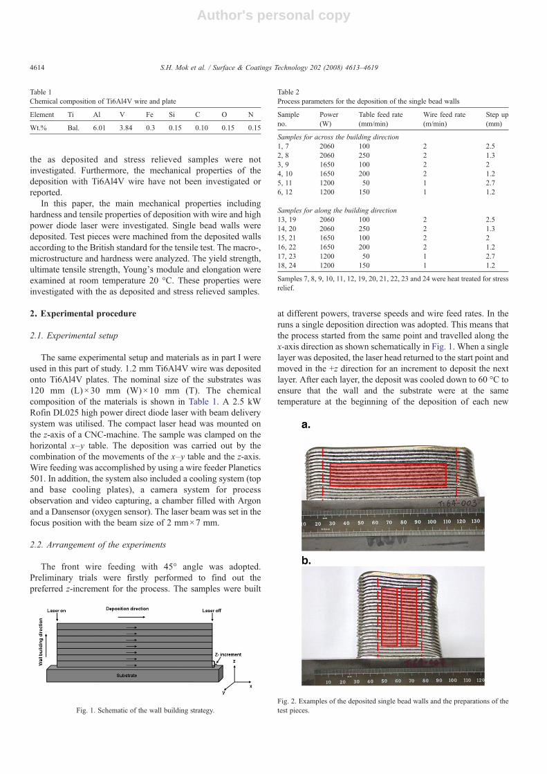
at different powers, traverse speeds and wire feed rates. In theruns a single deposition direction was adopted. This means thatthe process started from the same point and travelled along thex-axis direction as shown schematically in Fig. 1. When a singlelayer was deposited, the laser head returned to the start point andmoved in the +z direction for an increment to deposit the nextlayer. After each layer, the deposit was cooled down to 60 °C toensure that the wall and the substrate were at the sametemperature at the beginning of the deposition of each new
Table 1Chemical composition of Ti6Al4V wire and plate
Element Ti Al V Fe Si C O N
Wt.% Bal. 6.01 3.84 0.3 0.15 0.10 0.15 0.15
Fig. 1. Schematic of the wall building strategy.
Table 2Process parameters for the deposition of the single bead walls
Sampleno.
Power(W)
Table feed rate(mm/min)
Wire feed rate(m/min)
Step up(mm)
Samples for across the building direction1, 7 2060 100 2 2.52, 8 2060 250 2 1.33, 9 1650 100 2 24, 10 1650 200 2 1.25, 11 1200 50 1 2.76, 12 1200 150 1 1.2
Samples for along the building direction13, 19 2060 100 2 2.514, 20 2060 250 2 1.315, 21 1650 100 2 216, 22 1650 200 2 1.217, 23 1200 50 1 2.718, 24 1200 150 1 1.2
Samples 7, 8, 9, 10, 11, 12, 19, 20, 21, 22, 23 and 24 were heat treated for stressrelief.
Fig. 2. Examples of the deposited single bead walls and the preparations of thetest pieces.
4614 S.H. Mok et al. / Surface & Coatings Technology 202 (2008) 4613–4619
Author's personal copy
layer. Based on the preliminary experiments 80% of the layerheight was found to be the preferred z-increment according to themelt condition and appearance. Table 2 shows the processparameters in detail. Selected samples (no. 7, 8, 9, 10, 11, 12, 19,20, 21, 22, 23 and 24) were heat treated at 700 °C in an aircirculating furnace for 2 h for stress relief. After heat treatmentthe samples were machined to the required dimensions of thetensile test specimens. The samples were then subjected tomacro- and microstructure analysis, hardness test and tensile test.
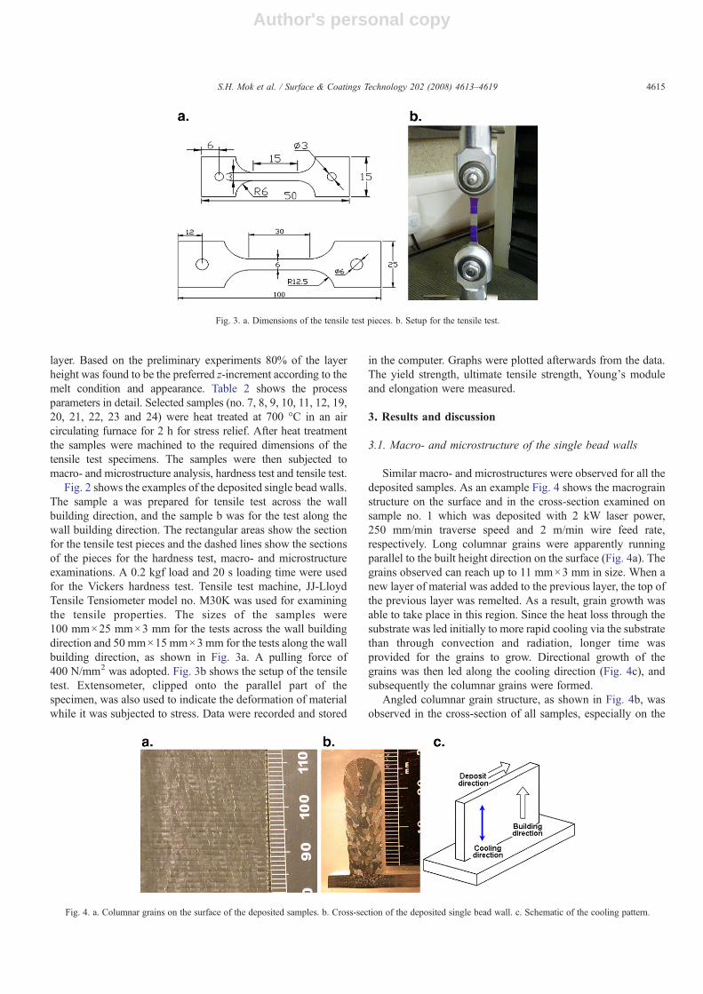
Fig. 2 shows the examples of the deposited single bead walls.The sample a was prepared for tensile test across the wallbuilding direction, and the sample b was for the test along thewall building direction. The rectangular areas show the sectionfor the tensile test pieces and the dashed lines show the sectionsof the pieces for the hardness test, macro- and microstructureexaminations. A 0.2 kgf load and 20 s loading time were usedfor the Vickers hardness test. Tensile test machine, JJ-LloydTensile Tensiometer model no. M30K was used for examiningthe tensile properties. The sizes of the samples were100 mm×25 mm×3 mm for the tests across the wall buildingdirection and 50 mm×15 mm×3 mm for the tests along the wallbuilding direction, as shown in Fig. 3a. A pulling force of400 N/mm2 was adopted. Fig. 3b shows the setup of the tensiletest. Extensometer, clipped onto the parallel part of thespecimen, was also used to indicate the deformation of materialwhile it was subjected to stress. Data were recorded and stored
in the computer. Graphs were plotted afterwards from the data.The yield strength, ultimate tensile strength, Young's moduleand elongation were measured.
3. Results and discussion
3.1. Macro- and microstructure of the single bead walls
Similar macro- and microstructures were observed for all thedeposited samples. As an example Fig. 4 shows the macrograinstructure on the surface and in the cross-section examined onsample no. 1 which was deposited with 2 kW laser power,250 mm/min traverse speed and 2 m/min wire feed rate,respectively. Long columnar grains were apparently runningparallel to the built height direction on the surface (Fig. 4a). Thegrains observed can reach up to 11 mm×3 mm in size. When anew layer of material was added to the previous layer, the top ofthe previous layer was remelted. As a result, grain growth wasable to take place in this region. Since the heat loss through thesubstrate was led initially to more rapid cooling via the substratethan through convection and radiation, longer time wasprovided for the grains to grow. Directional growth of thegrains was then led along the cooling direction (Fig. 4c), andsubsequently the columnar grains were formed.
Angled columnar grain structure, as shown in Fig. 4b, wasobserved in the cross-section of all samples, especially on the
Fig. 3. a. Dimensions of the tensile test pieces. b. Setup for the tensile test.
Fig. 4. a. Columnar grains on the surface of the deposited samples. b. Cross-section of the deposited single bead wall. c. Schematic of the cooling pattern.
4615S.H. Mok et al. / Surface & Coatings Technology 202 (2008) 4613–4619
Author's personal copy
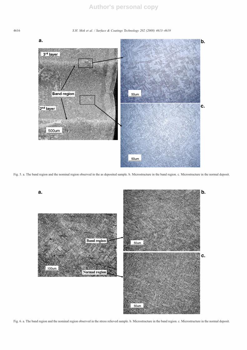
Fig. 5. a. The band region and the nominal region observed in the as deposited sample. b. Microstructure in the band region. c. Microstructure in the normal deposit.
Fig. 6. a. The band region and the nominal region observed in the stress relieved sample. b. Microstructure in the band region. c. Microstructure in the normal deposit.
4616 S.H. Mok et al. / Surface & Coatings Technology 202 (2008) 4613–4619
Author's personal copy
top part of the build. Similar macrostructure was also revealed inthe deposition of Ti6Al4V powder with laser [2–7]. Results showthat the angled growth of these columnar grains occurred due to thedirectional heating and cooling during the deposition. Thegrains inthe top region of the previous layer were partially remelted whichwould serve as nuclei and grew again epitaxially along the coolingdirection. The process was continued in the consecutive layersuntil the solidificationmechanism changedwhen heat loss throughthe substrate was no longer dominant in cooling.
As shown in Fig. 5a, there is a band region between twolayers of the single line walls, which was also observed bydeposition with Ti6Al4V powder [3–5]. The thickness of theband region is about 100 µm. The band region formed due to theremelting of previously deposited layer and multiple thermalcycles that had occurred with each subsequent deposition pass,as discussed in detail in [3–5]. Under the microscope, the bandregion (Fig. 5b) shows a colony Widmanstätten acicular α grain
structure. Whereas, the nominal microstructure in the depositexhibits a fine basket-weave Widmanstätten α morphology,which indicates a high cooling rate [4,5]. For the high laserpowers and low traverse speeds a thicker band region formedand coarser microstructure was obtained, whereas for the lowlaser powers and fast traverse speeds the microstructure becamefiner. Similar results were also revealed in the literatures [8,9].
Fig. 6 shows the microstructure observed on the stress relievedsample deposited with the same parameters as sample no. 1.Compared with the as deposit samples, no obvious phase change ofthe microstructure in the band region (Fig. 6b) and normal deposit(Fig. 6) was observed, because the heat treatment was carried outbelow the β-transus temperature (around 980 °C). However, thecoarser α colony Widmanstätten morphology was formed in thenominal deposit after the heat treatment. The difference of themicrostructure has an effect on the mechanical properties [10], aswill be discussed in Section 3.3.
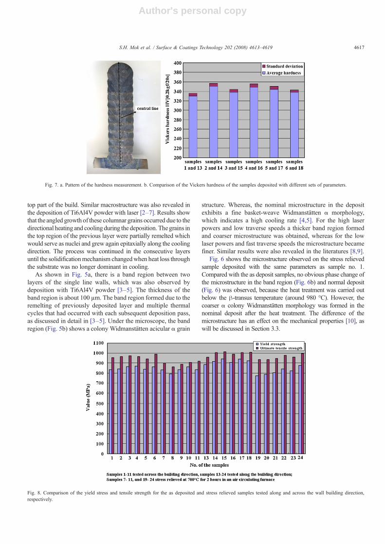
Fig. 7. a. Pattern of the hardness measurement. b. Comparison of the Vickers hardness of the samples deposited with different sets of parameters.
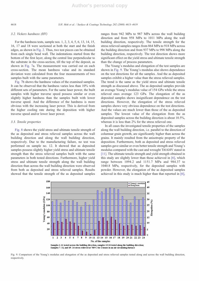
Fig. 8. Comparison of the yield stress and tensile strength for the as deposited and stress relieved samples tested along and across the wall building direction,respectively.
4617S.H. Mok et al. / Surface & Coatings Technology 202 (2008) 4613–4619
Author's personal copy
3.2. Vickers hardness (HV)
For the hardness tests, sample nos. 1, 2, 3, 4, 5, 6, 13, 14, 15,16, 17 and 18 were sectioned at both the start and the finishedges, as shown in Fig. 2. Thus, two test pieces can be obtainedfrom each single bead wall. The indentations started from thebottom of the first layer, along the central line perpendicular tothe substrate in the cross-section, till the top of the deposit, asshown in Fig. 7a. The measurement was carried out on eachcross-section. The mean hardness value and its standarddeviation were calculated from the four measurements of twosamples built with the same parameters.
Fig. 7b shows the hardness values of the examined samples.It can be observed that the hardness varies less than 10% withdifferent sets of parameters. For the same laser power, the builtsamples with higher traverse speed possess similar or evenslightly higher hardness than the samples built with lowertraverse speed. And the difference of the hardness is moreobvious with the increasing laser power. This is derived fromthe higher cooling rate during the deposition with highertraverse speed and/or lower laser power.
3.3. Tensile properties
Fig. 8 shows the yield stress and ultimate tensile strength ofthe as deposited and stress relieved samples across the wallbuilding direction and along the wall building direction,respectively. Due to the manufacturing failure, no test wasperformed on sample no. 12. It showed that as depositedsamples possess slightly higher yield stress and ultimate tensilestrength than the stress relieved samples built with the sameparameters in both tested directions. Furthermore, higher yieldstress and ultimate tensile strength along the wall buildingdirection than across the wall building direction were observedfrom both as deposited and stress relieved samples. Resultsshowed that the tensile strength of the as deposited samples
ranges from 942 MPa to 987 MPa across the wall buildingdirection and from 958 MPa to 1011 MPa along the wallbuilding direction, respectively. The tensile strength for thestress relieved samples ranges from 864 MPa to 918 MPa acrossthe building direction and from 937 MPa to 998 MPa along thebuilding direction, respectively. The test direction shows moresignificant effect on the yield stress and ultimate tensile strengththan the change of process parameters.
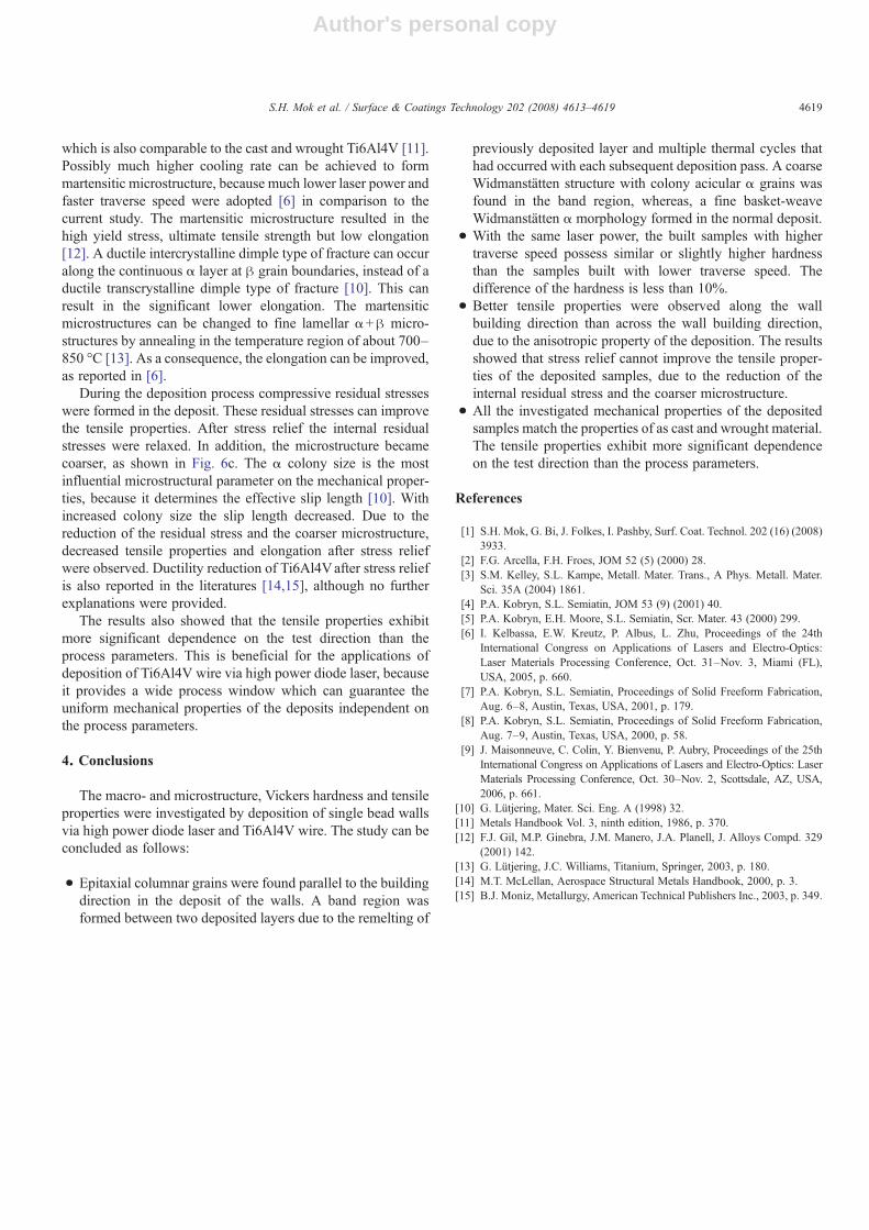
The Young's modulus and elongation of the test samples areshown in Fig. 9. The Young's modulus also shows dependenceon the test directions for all the samples. And the as depositedsamples exhibit a higher value than the stress relieved samples.The trend is the same as the yield stress and ultimate tensilestrength as discussed above. The as deposited samples providean average Young's modulus value of 154 GPa while the stressrelieved ones average 123 GPa. The elongation of the asdeposited samples shows insignificant dependence on the testdirections. However, the elongation of the stress relievedsamples shows very obvious dependence on the test directions.And the values are much lower than those of the as depositedsamples. The lowest value of the elongation from the asdeposited samples across the building direction is about 10.5%,whereas it is less than 2% for the stress relieved one.
In all cases the investigated tensile properties of the samplesalong the wall building direction, i.e. parallel to the direction ofcolumnar grain growth, are significantly higher than across thegrains. It mainly resulted from the anisotropic property of thedeposition. Furthermore, both as deposited and stress relievedsamples gave similar or even better tensile strength and Young'smodulus compared with the cast and wrought Ti6Al4V stated in[11]. The ultimate tensile strength and yield strength obtained inthis study are slightly lower than those achieved in [6], whichrange between 1094.2 and 1151.7 MPa and 984.37 to1040.8 MPa, respectively, for the deposited samples withpowder. However, the elongation of the as deposited samplesachieved in this study is much higher than that reported in [6],
Fig. 9. Comparison of the Young's modulus and elongation of the as deposited and stress relieved samples tested along and across the wall building direction,respectively.
4618 S.H. Mok et al. / Surface & Coatings Technology 202 (2008) 4613–4619
Author's personal copy
which is also comparable to the cast and wrought Ti6Al4V [11].Possibly much higher cooling rate can be achieved to formmartensitic microstructure, because much lower laser power andfaster traverse speed were adopted [6] in comparison to thecurrent study. The martensitic microstructure resulted in thehigh yield stress, ultimate tensile strength but low elongation[12]. A ductile intercrystalline dimple type of fracture can occuralong the continuous α layer at β grain boundaries, instead of aductile transcrystalline dimple type of fracture [10]. This canresult in the significant lower elongation. The martensiticmicrostructures can be changed to fine lamellar α+β micro-structures by annealing in the temperature region of about 700–850 °C [13]. As a consequence, the elongation can be improved,as reported in [6].
During the deposition process compressive residual stresseswere formed in the deposit. These residual stresses can improvethe tensile properties. After stress relief the internal residualstresses were relaxed. In addition, the microstructure becamecoarser, as shown in Fig. 6c. The α colony size is the mostinfluential microstructural parameter on the mechanical proper-ties, because it determines the effective slip length [10]. Withincreased colony size the slip length decreased. Due to thereduction of the residual stress and the coarser microstructure,decreased tensile properties and elongation after stress reliefwere observed. Ductility reduction of Ti6Al4Vafter stress reliefis also reported in the literatures [14,15], although no furtherexplanations were provided.
The results also showed that the tensile properties exhibitmore significant dependence on the test direction than theprocess parameters. This is beneficial for the applications ofdeposition of Ti6Al4V wire via high power diode laser, becauseit provides a wide process window which can guarantee theuniform mechanical properties of the deposits independent onthe process parameters.
4. Conclusions
The macro- and microstructure, Vickers hardness and tensileproperties were investigated by deposition of single bead wallsvia high power diode laser and Ti6Al4V wire. The study can beconcluded as follows:
• Epitaxial columnar grains were found parallel to the buildingdirection in the deposit of the walls. A band region wasformed between two deposited layers due to the remelting of
previously deposited layer and multiple thermal cycles thathad occurred with each subsequent deposition pass. A coarseWidmanstätten structure with colony acicular α grains wasfound in the band region, whereas, a fine basket-weaveWidmanstätten α morphology formed in the normal deposit.
• With the same laser power, the built samples with highertraverse speed possess similar or slightly higher hardnessthan the samples built with lower traverse speed. Thedifference of the hardness is less than 10%.
• Better tensile properties were observed along the wallbuilding direction than across the wall building direction,due to the anisotropic property of the deposition. The resultsshowed that stress relief cannot improve the tensile proper-ties of the deposited samples, due to the reduction of theinternal residual stress and the coarser microstructure.
• All the investigated mechanical properties of the depositedsamples match the properties of as cast and wrought material.The tensile properties exhibit more significant dependenceon the test direction than the process parameters.
References
[1] S.H. Mok, G. Bi, J. Folkes, I. Pashby, Surf. Coat. Technol. 202 (16) (2008)3933.
[2] F.G. Arcella, F.H. Froes, JOM 52 (5) (2000) 28.[3] S.M. Kelley, S.L. Kampe, Metall. Mater. Trans., A Phys. Metall. Mater.
Sci. 35A (2004) 1861.[4] P.A. Kobryn, S.L. Semiatin, JOM 53 (9) (2001) 40.[5] P.A. Kobryn, E.H. Moore, S.L. Semiatin, Scr. Mater. 43 (2000) 299.[6] I. Kelbassa, E.W. Kreutz, P. Albus, L. Zhu, Proceedings of the 24th
International Congress on Applications of Lasers and Electro-Optics:Laser Materials Processing Conference, Oct. 31–Nov. 3, Miami (FL),USA, 2005, p. 660.
[7] P.A. Kobryn, S.L. Semiatin, Proceedings of Solid Freeform Fabrication,Aug. 6–8, Austin, Texas, USA, 2001, p. 179.
[8] P.A. Kobryn, S.L. Semiatin, Proceedings of Solid Freeform Fabrication,Aug. 7–9, Austin, Texas, USA, 2000, p. 58.
[9] J. Maisonneuve, C. Colin, Y. Bienvenu, P. Aubry, Proceedings of the 25thInternational Congress on Applications of Lasers and Electro-Optics: LaserMaterials Processing Conference, Oct. 30–Nov. 2, Scottsdale, AZ, USA,2006, p. 661.
[10] G. Lütjering, Mater. Sci. Eng. A (1998) 32.[11] Metals Handbook Vol. 3, ninth edition, 1986, p. 370.[12] F.J. Gil, M.P. Ginebra, J.M. Manero, J.A. Planell, J. Alloys Compd. 329
(2001) 142.[13] G. Lütjering, J.C. Williams, Titanium, Springer, 2003, p. 180.[14] M.T. McLellan, Aerospace Structural Metals Handbook, 2000, p. 3.[15] B.J. Moniz, Metallurgy, American Technical Publishers Inc., 2003, p. 349.
4619S.H. Mok et al. / Surface & Coatings Technology 202 (2008) 4613–4619