Time and space-resolved dynamic studies on ceramic and cementitious materials
11
J. Synchrotron Rad. (2000). 7, 167–177 Time- and space-resolved dynamic studies on ceramic and cementitious materials Paul Barnes, a * Sally Colston, a Bernadette Craster, b Chris Hall, b ² Andrew Jupe, a Simon Jacques, a Jeremy Cockcroft, a Shane Morgan, a M. Johnson, a D. O’Connor a and M. Bellotto c a Industrial Materials Group, Department of Crystallography, Birkbeck College, Malet Street, London WC1E 7HX, UK, b Schlumberger Cambridge Research Ltd, High Cross, Madingley Road, Cambridge CB3 OEL, UK, and c CTG Italcementi Group, Rue des Technodes, 78931 Guerville, France. E-mail: [email protected] (Received 20 January 2000; accepted 28 February 2000 ) A review is given of the results and lessons arising from a sustained in situ diffraction study of the structure and performance of functional ceramic/cementitious materials in which synchrotron-based energy-dispersive diffraction has been the central under-pinning technique. Five particular points of discussion emerge: the demands on time resolution; the use of penetrating radiation for the in situ mode; the need for complementary techniques; re-analysing of data; spatially resolved diffraction: a new tomography. These aspects are discussed in turn using illustrative examples taken from the fields of cement hydration, clay intercalation, cation-exchanged zeolites, and particulate/fluid invasion into building and archaeological objects. Keywords: diffraction; tomography; cements; ceramics. 1. Time resolution Rapid data collection has been a long-standing pursuit of the synchrotron and neutron radiation communities; spec- tacular time resolutions, approaching hundreds of femto- seconds, have been obtained in highly specialized situations (e.g. Wark, 1999). The experience gained within these studies on bulk solid-state chemistry systems is that the most frequently needed time resolutions lie in the 1 s to 5 min timescale, which is conveniently well matched to the performance of current conventional energy-dispersive detector systems (useful count rates in the 10 4 – 10 5 counts s 1 range). Synchrotron-based angle-scanning (monochromatic) diffraction is now also capable of deli- vering sub-minute powder patterns of sufficient quality sometimes for Rietveld structure refinement (e.g. Svensson et al., 1997; Norby et al. , 1999). Thus the distinguishing advantages of the energy-dispersive diffraction (EDD) method lie mainly in flexibility with respect to complex specimen environments and very short timescales (1 s or less). In the following we present two illustrative examples where these two attributes were essential. 1.1. Intercalation of clays Research into the fundamentals of hydration and inter- calation in swelling clays is an important topic for the oil industry. It has led to significant advances in the technology of shale stabilization during drilling (Boek et al., 1998) and gives new insight into the diagenesis of clays and their behaviour under reservoir conditions (De Siqueira et al., 1999). Molecular modelling of the interlayer space in the presence of water, ions (Boek et al., 1995) and intercalation species such as polyglycols (Boek et al., 1998) has been used successfully in interpreting high-quality neutron diffraction data (Skipper et al., 1995). In situ EDD has also become accepted as a valuable adjunct (Redfern, 1987; Bray & Redfern, 1999; Fogg & O’Hare, 1999) to more traditional methods (e.g. neutron and conventional diffraction, thermo-gravimetric techniques) for studying intercalation within layered minerals (e.g. kaolinite, montmorillonite, gibbsite) providing data for kinetic analysis (use of rate equations and Arrhenius plots) and elucidating the reac- tion pathways (presence of intermediates etc.). In the case presented here it turns out that the ability with EDD to be able to spatially resolve the intercalation has been a key additional feature. For example, very rapid changes in interlayer spacing have been observed when an 8 wt% KCl solution is injected (via a remotely controlled solenoid valve) into a stirred suspension of Na-montmorillonite pretreated with polyglycol. The reduction of basal spacing from 1.8 to 1.5 nm corresponds to the removal of one layer of water molecules. In this experiment, EDD patterns were collected in 1 s at intervals of 7 s (Fig. 1a). Such ion- exchange experiments can be carried out on dilute suspensions, typical of processes occurring in colloidal clay aggregates in dilute suspension, as well as in dense clay 167 # 2000 International Union of Crystallography Journal of Synchrotron Radiation Printed in Great Britain – all rights reserved ISSN 0909-0495 # 2000 ² Now at Centre for Materials Science and Engineering, University of Edinburgh, Edinburgh EH9 3JL, UK.
-
Upload
independent -
Category
Documents
-
view
3 -
download
0
Transcript of Time and space-resolved dynamic studies on ceramic and cementitious materials

J. Synchrotron Rad. (2000). 7, 167±177
Time- and space-resolved dynamic studies on ceramic andcementitious materials
Paul Barnes,a* Sally Colston,a Bernadette Craster,b Chris Hall,b² Andrew Jupe,a
Simon Jacques,a Jeremy Cockcroft,a Shane Morgan,a M. Johnson,a D.O'Connora and M. Bellottoc
aIndustrial Materials Group, Department of Crystallography, Birkbeck College, Malet Street,London WC1E 7HX, UK, bSchlumberger Cambridge Research Ltd, High Cross, MadingleyRoad, Cambridge CB3 OEL, UK, and cCTG Italcementi Group, Rue des Technodes, 78931Guerville, France. E-mail: [email protected]
(Received 20 January 2000; accepted 28 February 2000 )
A review is given of the results and lessons arising from a sustained in situ diffraction study of the
structure and performance of functional ceramic/cementitious materials in which synchrotron-based
energy-dispersive diffraction has been the central under-pinning technique. Five particular points of
discussion emerge: the demands on time resolution; the use of penetrating radiation for the in situ
mode; the need for complementary techniques; re-analysing of data; spatially resolved diffraction: a
new tomography. These aspects are discussed in turn using illustrative examples taken from the ®elds
of cement hydration, clay intercalation, cation-exchanged zeolites, and particulate/¯uid invasion into
building and archaeological objects.
Keywords: diffraction; tomography; cements; ceramics.
1. Time resolution
Rapid data collection has been a long-standing pursuit of
the synchrotron and neutron radiation communities; spec-
tacular time resolutions, approaching hundreds of femto-
seconds, have been obtained in highly specialized situations
(e.g. Wark, 1999). The experience gained within these
studies on bulk solid-state chemistry systems is that the
most frequently needed time resolutions lie in the 1 s to
5 min timescale, which is conveniently well matched to the
performance of current conventional energy-dispersive
detector systems (useful count rates in the 104±
105 counts sÿ1 range). Synchrotron-based angle-scanning
(monochromatic) diffraction is now also capable of deli-
vering sub-minute powder patterns of suf®cient quality
sometimes for Rietveld structure re®nement (e.g. Svensson
et al., 1997; Norby et al., 1999). Thus the distinguishing
advantages of the energy-dispersive diffraction (EDD)
method lie mainly in ¯exibility with respect to complex
specimen environments and very short timescales (1 s or
less). In the following we present two illustrative examples
where these two attributes were essential.
1.1. Intercalation of clays
Research into the fundamentals of hydration and inter-
calation in swelling clays is an important topic for the oil
industry. It has led to signi®cant advances in the technology
of shale stabilization during drilling (Boek et al., 1998) and
gives new insight into the diagenesis of clays and their
behaviour under reservoir conditions (De Siqueira et al.,
1999). Molecular modelling of the interlayer space in the
presence of water, ions (Boek et al., 1995) and intercalation
species such as polyglycols (Boek et al., 1998) has been used
successfully in interpreting high-quality neutron diffraction
data (Skipper et al., 1995). In situ EDD has also become
accepted as a valuable adjunct (Redfern, 1987; Bray &
Redfern, 1999; Fogg & O'Hare, 1999) to more traditional
methods (e.g. neutron and conventional diffraction,
thermo-gravimetric techniques) for studying intercalation
within layered minerals (e.g. kaolinite, montmorillonite,
gibbsite) providing data for kinetic analysis (use of rate
equations and Arrhenius plots) and elucidating the reac-
tion pathways (presence of intermediates etc.). In the case
presented here it turns out that the ability with EDD to be
able to spatially resolve the intercalation has been a key
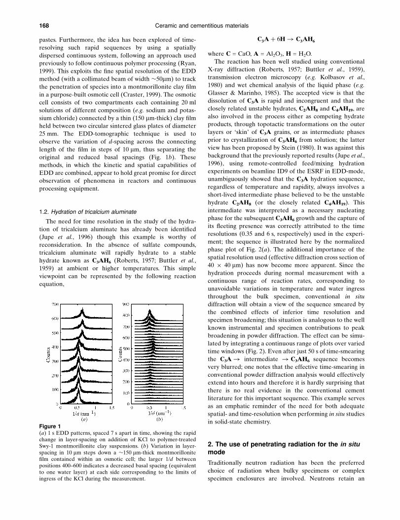
additional feature. For example, very rapid changes in
interlayer spacing have been observed when an 8 wt% KCl
solution is injected (via a remotely controlled solenoid
valve) into a stirred suspension of Na-montmorillonite
pretreated with polyglycol. The reduction of basal spacing
from 1.8 to 1.5 nm corresponds to the removal of one layer
of water molecules. In this experiment, EDD patterns were
collected in 1 s at intervals of 7 s (Fig. 1a). Such ion-
exchange experiments can be carried out on dilute
suspensions, typical of processes occurring in colloidal clay
aggregates in dilute suspension, as well as in dense clay
167
# 2000 International Union of Crystallography Journal of Synchrotron Radiation
Printed in Great Britain ± all rights reserved ISSN 0909-0495 # 2000
² Now at Centre for Materials Science and Engineering, University ofEdinburgh, Edinburgh EH9 3JL, UK.
168 Ceramic and cementitious materials
pastes. Furthermore, the idea has been explored of time-
resolving such rapid sequences by using a spatially
dispersed continuous system, following an approach used
previously to follow continuous polymer processing (Ryan,
1999). This exploits the ®ne spatial resolution of the EDD
method (with a collimated beam of width �50mm) to track
the penetration of species into a montmorillonite clay ®lm
in a purpose-built osmotic cell (Craster, 1999). The osmotic
cell consists of two compartments each containing 20 ml
solutions of different composition (e.g. sodium and potas-
sium chloride) connected by a thin (150 mm-thick) clay ®lm
held between two circular sintered glass plates of diameter
25 mm. The EDD-tomographic technique is used to
observe the variation of d-spacing across the connecting
length of the ®lm in steps of 10 mm, thus separating the
original and reduced basal spacings (Fig. 1b). These
methods, in which the kinetic and spatial capabilities of
EDD are combined, appear to hold great promise for direct
observation of phenomena in reactors and continuous
processing equipment.
1.2. Hydration of tricalcium aluminate
The need for time resolution in the study of the hydra-
tion of tricalcium aluminate has already been identi®ed
(Jupe et al., 1996) though this example is worthy of
reconsideration. In the absence of sulfate compounds,
tricalcium aluminate will rapidly hydrate to a stable
hydrate known as C3AH6 (Roberts, 1957; Buttler et al.,
1959) at ambient or higher temperatures. This simple
viewpoint can be represented by the following reaction
equation,
C3A� 6H! C3AH6
where C = CaO, A = Al2O3, H = H2O.
The reaction has been well studied using conventional
X-ray diffraction (Roberts, 1957; Buttler et al., 1959),
transmission electron microscopy (e.g. Kolbasov et al.,
1980) and wet chemical analysis of the liquid phase (e.g.
Glasser & Marinho, 1985). The accepted view is that the
dissolution of C3A is rapid and incongruent and that the
closely related unstable hydrates, C2AH8 and C4AH19, are
also involved in the process either as competing hydrate
products, through topotactic transformations on the outer
layers or `skin' of C3A grains, or as intermediate phases
prior to crystallization of C3AH6 from solution; the latter
view has been proposed by Stein (1980). It was against this
background that the previously reported results (Jupe et al.,
1996), using remote-controlled feed/mixing hydration
experiments on beamline ID9 of the ESRF in EDD-mode,
unambiguously showed that the C3A hydration sequence,
regardless of temperature and rapidity, always involves a
short-lived intermediate phase believed to be the unstable
hydrate C2AH8 (or the closely related C4AH19). This
intermediate was interpreted as a necessary nucleating
phase for the subsequent C3AH6 growth and the capture of
its ¯eeting presence was correctly attributed to the time
resolutions (0.35 and 6 s, respectively) used in the experi-
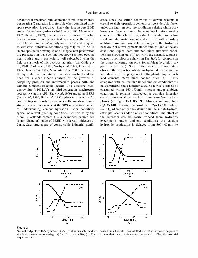
ment; the sequence is illustrated here by the normalized
phase plot of Fig. 2(a). The additional importance of the
spatial resolution used (effective diffraction cross section of
40 � 40 mm) has now become more apparent. Since the
hydration proceeds during normal measurement with a
continuous range of reaction rates, corresponding to
unavoidable variations in temperature and water ingress
throughout the bulk specimen, conventional in situ
diffraction will obtain a view of the sequence smeared by
the combined effects of inferior time resolution and
specimen broadening; this situation is analogous to the well
known instrumental and specimen contributions to peak
broadening in powder diffraction. The effect can be simu-
lated by integrating a continuous range of plots over varied
time windows (Fig. 2). Even after just 50 s of time-smearing
the C3A! intermediate ! C3AH6 sequence becomes
very blurred; one notes that the effective time-smearing in
conventional powder diffraction analysis would effectively
extend into hours and therefore it is hardly surprising that
there is no real evidence in the conventional cement
literature for this important sequence. This example serves
as an emphatic reminder of the need for both adequate
spatial- and time-resolution when performing in situ studies
in solid-state chemistry.
2. The use of penetrating radiation for the in situmode
Traditionally neutron radiation has been the preferred
choice of radiation when bulky specimens or complex
specimen enclosures are involved. Neutrons retain an
Figure 1(a) 1 s EDD patterns, spaced 7 s apart in time, showing the rapidchange in layer-spacing on addition of KCl to polymer-treatedSwy-1 montmorillonite clay suspensions. (b) Variation in layer-spacing in 10 mm steps down a �150 mm-thick montmorillonite®lm contained within an osmotic cell; the larger 1/d betweenpositions 400±600 indicates a decreased basal spacing (equivalentto one water layer) at each side corresponding to the limits ofingress of the KCl during the measurement.
Paul Barnes et al. 169
advantage if specimen-bulk averaging is required whereas
penetrating X-radiation is preferable when combined time/
space-resolution is required. Since the ®rst in situ EDD
study of autoclave synthesis (Polak et al., 1990; Munn et al.,
1992; He et al., 1992), energetic synchrotron radiation has
been increasingly used to penetrate specimen cells made of
metal (steel, aluminium) or polymer (PEEK) and designed
to withstand autoclave conditions, typically 403 to 523 K
(more spectacular examples of bulk specimen penetration
are presented in x5). Such methodology has now become
near-routine and is particularly well subscribed to in the
®eld of synthesis of microporous materials (e.g. O'Hare et
al., 1998; Clark et al., 1995; Norby et al., 1999; Lewis et al.,
1995; Davies et al., 1997; Muncaster et al., 2000) because of
the hydrothermal conditions invariably involved and the
need for a clear kinetic analysis of the growths of
competing products and intermediate phases, with and
without template-directing agents. The effective high-
energy ¯ux (>100 keV) on third-generation synchrotron
sources [e.g. at the APS (Shaw et al., 1999) and at the ESRF
(Jupe et al., 1996; Hall et al., 1998)] gives further scope for
constructing more robust specimen cells. We show here a
study example, undertaken at the SRS synchrotron, aimed
at understanding cement hydration under conditions
typical of oilwell grouting conditions. For this study the
oilwell (Portland) cement ®lls a cylindrical sample cell
(8 mm diameter) made of PEEK with a wall thickness of
2 mm. Such studies are of considerable industrial signi®-
cance since the setting behaviour of oilwell cements is
crucial to their operation: cements set considerably faster
under the high-temperature conditions existing within bore
holes yet placement must be completed before setting
commences. To achieve this, oilwell cements have a low
tricalcium aluminate content and are used with retarding
additives. We are now able to compare the hydration
behaviour of oilwell cements under ambient and autoclave
conditions. Typical data obtained under autoclave condi-
tions are shown in Fig. 3(a) for which the normalized phase-
concentration plots are shown in Fig. 3(b); for comparison
the phase-concentration plots for ambient hydration are
given in Fig. 3(c). Some differences are immediately
obvious: the production of calcium hydroxide, often used as
an indicator of the progress of setting/hardening in Port-
land cements, starts much sooner, after 160±170 min
compared with 300±400 min under ambient conditions; the
brownmillerite phase (calcium alumino-ferrite) starts to be
consumed within 160±170 min whereas under ambient
conditions it remains unaffected; a complex interplay
occurs between three calcium alumino-sulfate hydrate
phases (ettringite C3A.3Cs.32H; 14-water monosulphate
C3A.Cs.14H; 12-water monosulphate C3A.Cs.12H; where
s = SO3) whereas only one calcium alumino-sulfate hydrate,
ettringite, occurs under ambient conditions. The effect of
the retarders can be easily evinced from hydration
experiments under ambient conditions: the calcium
hydroxide production is delayed from 300±400 min to
Figure 2Normalized plots of C3A hydration (C3A ± continuous; intermediate ± dashed; ®nal hydrate ± dash/dotted curves) with various degrees ofsimulated space-time smearing: (a) 5 s, (b) 10 s, (c) 20 s, (d) 50 s. It is clear that once the time-smearing exceeds �50 s, the essentialsequence is lost.

170 Ceramic and cementitious materials
beyond the total experimental measurement time
(620 min) in the case of two typical retarder types (Fig. 4a),
and the consumption pro®le of ettringite under autoclave
conditions is also modi®ed by the same retarders (Fig. 4b).
These differences are now being used to test existing ideas
regarding the retardation mechanisms involved and to
provide a behavioural baseline from which to assess novel
retarders. It is dif®cult to imagine any alternative metho-
dology which could so conveniently and effectively provide
in situ data on these bulk hydrating systems.
3. Use of complementary and combined in situtechniques
The application of several complementary techniques to a
single problem is becoming increasingly recognized as an
effective means of pooling together different structural
views on a chemical/materials event. An excellent review of
this approach has been provided by Cheetham & Mellot
(1997) where various combinations of diffraction (labora-
tory, synchrotron X-rays, neutrons), small-angle scattering
(X-rays, neutrons), spectroscopy/resonance methods
(X-ray absorption spectroscopy, nuclear magnetic reso-
nance, vibrational spectroscopy) and imaging (optical,
electron, atomic force) have been applied to in situ studies
of sol±gel synthesis processes. A further subset of this
approach is to perform two or more complementary tech-
niques simultaneously in time. In the opinion of the authors
this further approach is best served by repeating a given
experiment in both combined and individual technique
mode: the former is necessary to bring the information
from each technique into time registration, while the latter
ensures that essential information is not marred by the
inevitable compromises that have to be made with
combined technique stations. A very recent example of the
combined technique approach can be seen with the
building of the new ten-pole wiggler station on the
Daresbury SRS (Cernik et al., 1999±2001) which will
combine three techniques, powder X-ray diffraction, small-
angle scattering and EXAFS, with multi-wire detector
technology capable of capturing data sets within 10 s. In the
following we provide three illustrative examples where
Figure 3Time-resolved EDD data on oilwell Portland cements hydrating at403 K under autoclave (a,b) and ambient (c) conditions. (a) Athree-dimensional view of the autoclave sequence (hydrothermalconditions, temperature ramp 303±403 K, over 2 h) in which themain phases are indicated. (b) The corresponding phaseconcentration plots, in which the coded phases are maximallynormalized to 1.0, together with the actual autoclave temperaturepro®le attained; (c) An equivalent phase concentration plot forhydration under ambient conditions. The autoclave displays morerapid hydration and a more complex interplay between themonosulphate and ettringite phases.

Paul Barnes et al. 171
complementary/combined techniques have provided both
challenge and eventual elucidation and in which energy-
dispersive diffraction played a central role.
3.1. Calcination of zirconium hydroxide to zirconia
This concerns previously published studies (Turrillas et
al., 1995) into the structural and kinetic aspects of this
amorphous-to-crystalline reaction-transformation which
has now become the subject of visual and computational
modelling methods (Cerius 2 Visualizer; Molecular Simu-
lations, CA, USA). The raw data obtained from X-ray
diffraction, neutron scattering and Zr-EXAFS experiments
super®cially look very different, with two of these techni-
ques, X-ray diffraction and Zr-EXAFS, having also been
performed in combined technique mode on station 9.3 of
the SRS. The basic information provided by each technique
can be brie¯y summarized as follows:
(i) X-ray diffraction (both energy- and angle-dispersive
modes) gave the least information on the amorphous
hydroxide structure, but was the simplest way to gain
kinetic data on the amorphous hydroxide to tetragonal
oxide and tetragonal to monoclinic oxide transformation as
a function of starting material, heating/cooling rate and top
temperature.
(ii) Neutron scattering, employed (at ILL and ISIS) with
various isotopic/group substitutions (i.e. ODÿ/D2O and
CH3Oÿ/CH3OH for OHÿ/H2O), was able to provide, from
the level of incoherent background scattering, direct
information on the combined hydroxide/water content at
each stage of the calcination, particularly over the ®nal
cooperative oxolation/crystallization stage around 773 K.
(iii) Zr K-edge EXAFS, combined with information from
the above and the existing literature, was able to interpret
the ®rst [ZrÐOÐ at 2.08 AÊ , ZrÐ(OH)2Ð and ZrÐH2O at
2.16 AÊ ] and second [ZrÐOÐZr at 3.27 AÊ and
Zr<(OH)2>Zr at 3.41 AÊ ] Zr-coordination shells in terms of
a generic `hydroxide' two-dimensional nucleating unit.
These very different views can be brought together in an
illustrative way using the graphic model representations
shown in Fig. 5. As such it remains a good example of the
elucidating power of multi-techniques.
3.2. The structure and hydration of doped brownmillerites
This case presents a contrasting example to the above in
which complementary `static' structural characterization
techniques have resulted in partially contradictory views.
Brownmillerite is the mineral name given to the calcium
alumino-ferrite cement phase which has a stoichiometric
composition of C4AF (C = CaO; A = Al2O3; F = Fe2O3) and
a perovskite-type structure (Bertaut et al., 1959; Colville &
Geller, 1971) in which Al and Fe occupy the tetrahedrally
and octahedrally coordinated sites with a statistical
preference of 3:1 and 1:3, respectively (Jupe, 1997).
However, in real Portland cements (Hall & Scrivener, 1998)
the brownmillerite Al:Fe ratio varies and, furthermore,
impurities such as Mg and Si substitute for Al and Fe in an,
as yet, undetermined way. In an attempt to resolve this
latter ambiguity, a combined X-ray/neutron diffraction
analysis was performed on a synthetic brownmillerite with
composition Ca4Al1.9Fe1.9Mg0.1Si0.1O10. A combined
neutron/X-ray Rietveld re®nement procedure has been
devised (Jupe et al., 2000) to overcome the under-deter-
minancy resulting from the unknown statistical occupations
of Fe, Al and Mg within the structure. This re®nement
indicates a similar Al,Fe-occupation scheme as that with
pure brownmillerite but with the Mg preferring wholly
tetrahedral or octahedral, rather than mixed, coordination;
the re®nement suggests a very slight preference (i.e. by
tenths of a % in the Rwp-factor) for the tetrahedral coor-
dination whereas Mg-XANES analysis on station 3.4 of the
SRS yields an octahedral XANES signature. That Mg
prefers an ordered occupational scheme is interesting given
that in situ energy-dispersive diffraction shows the Mg-
doped brownmillerites to be less reactive than the pure
forms (Jupe et al., 2000), suggesting that the Mg adopts a
structure-stabilizing role. This example serves as a
reminder of the need to con®rm ambiguous structural
analyses with additional complementary data.
3.3. The high-temperature stability of cation-exchangedclinoptilolite
The behaviour of clinoptilolite, treated with various
cation-exchange scenarios, is being studied in order to
understand the potential of this naturally abundant zeolite
for industrial separation and ®xation processes. The treat-
ment stages of interest commence from the as-given clin-
optilolite, followed by hydration at ambient conditions,
exchange to the cation state of interest, activation by
Figure 4(a) Calcium hydroxide pro®les. (b) Ettringite pro®les. Data fromtime-resolved EDD experiments on the hydration of oilwellcement (with and without two typical retarders calcium gluconate;phosphonate) under ambient conditions. The calcium hydroxideproduction is delayed (a) by the retarders from 300±400 min(without retarder) to beyond the total experimental measurementtime (620 min), whereas the change in consumption pro®le ofettringite is more subtle (b).

172 Ceramic and cementitious materials
Figure 5Four computer-graphic illustrations of various stages during the calcination of amorphous zirconium hydroxide to crystalline oxide, asevinced from X-ray/neutron diffraction and Zr-EXAFS data. (a) Initial array of highly hydrated hydroxide units; (b) close up of hydratedhydroxide unit as a defective distorted two-dimensional raft; (c) the same unit after further calcination/dehydration; (d) condensation ofrafts at the early stages of three-dimensional crystallization.
Paul Barnes et al. 173
calcination (typically to 623 K), and ®nally thermal
destruction (typically 1273 K). The ®rst study was on a
mixed Ca,K-cation system and demonstrated the combi-
nation of three techniques: high-resolution powder X-ray
diffraction, Ca,K-EXAFS and Grand Canonical Monte-
Carlo-type computer simulations by which the cation/water
content could be varied in order to elucidate likely cation
locations as the dehydrated/activated structure was
approached; this indicated a valve-type mechanism in
which gaseous ¯ow through the zeolite is restricted in
either direction by the K cations projecting into the main
zeolite channel (O'Connor et al., 1998). The main problem
in this study was the poor quality of available clinoptilolite
powders: the natural minerals have poor crystallinity
whereas the few successfully synthesized versions are
multi-phasic, and so the main value of the complementary
methods here was rather to compensate for the restricted
quality of the experimental data. However, the metho-
dology devised is now being extended to look at other
cation combinations, including the Cs form (ideal formula
Si30Al6O22Cs6) which is implicated in the radioactive ion
extraction from contaminated water supplies, and to also
examine the intermediate hydration/dehydration stages
using rapid combined diffraction/EXAFS facilities (Cernik
et al., 1999±2001). An additional interest has now arisen
concerning the high-temperature stability of these various
systems and a temperature/time-resolved energy-dispersive
diffraction protocol is being tested as a rapid comparative
method of assessment: the temperature at which crystal-
linity is destroyed and the detailed diffraction behaviour
prior to the structural collapse are found to be quite
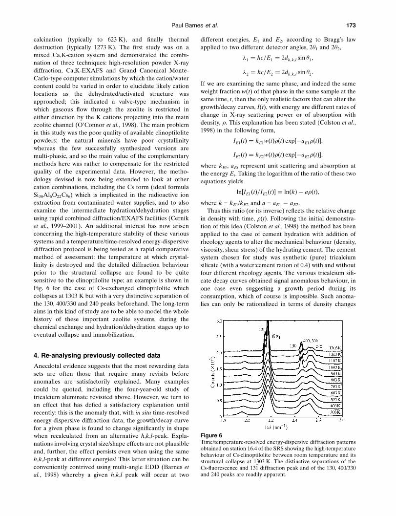
sensitive to the clinoptilolite type; an example is shown in
Fig. 6 for the case of Cs-exchanged clinoptilolite which
collapses at 1303 K but with a very distinctive separation of
the 130, 400/330 and 240 peaks beforehand. The long-term
aims in this kind of study are to be able to model the whole
history of these important zeolite systems, during the
chemical exchange and hydration/dehydration stages up to
eventual collapse and immobilization.
4. Re-analysing previously collected data
Anecdotal evidence suggests that the most rewarding data
sets are often those that require many revisits before
anomalies are satisfactorily explained. Many examples
could be quoted, including the four-year-old study of
tricalcium aluminate revisited above. However, we turn to
an effect that has de®ed a satisfactory explanation until
recently: this is the anomaly that, with in situ time-resolved
energy-dispersive diffraction data, the growth/decay curve
for a given phase is found to change signi®cantly in shape
when recalculated from an alternative h,k,l-peak. Expla-
nations involving crystal size/shape effects are not plausible
and, further, the effect persists even when using the same
h,k,l-peak at different energies! This latter situation can be
conveniently contrived using multi-angle EDD (Barnes et
al., 1998) whereby a given h,k,l peak will occur at two
different energies, E1 and E2, according to Bragg's law
applied to two different detector angles, 2�1 and 2�2,
�1 � hc=E1 � 2dh;k;l sin �1;
�2 � hc=E2 � 2dh;k;l sin �2:
If we are examining the same phase, and indeed the same
weight fraction w(t) of that phase in the same sample at the
same time, t, then the only realistic factors that can alter the
growth/decay curves, I(t), with energy are different rates of
change in X-ray scattering power or of absorption with
density, �. This explanation has been stated (Colston et al.,
1998) in the following form,
IE1�t� � kE1w�t���t� exp�ÿaE1��t��;IE2�t� � kE2w�t���t� exp�ÿaE2��t��;
where kEi , aEi represent unit scattering and absorption at
the energy Ei. Taking the logarithm of the ratio of these two
equations yields
ln�IE1�t�=IE2�t�� � ln�k� ÿ a��t�;where k = kE1/kE2 and a = aE1 ÿ aE2.
Thus this ratio (or its inverse) re¯ects the relative change
in density with time, �(t). Following the initial demonstra-
tion of this idea (Colston et al., 1998) the method has been
applied to the case of cement hydration with addition of
rheology agents to alter the mechanical behaviour (density,
viscosity, shear stress) of the hydrating cement. The cement
system chosen for study was synthetic (pure) tricalcium
silicate (with a water:cement ration of 0.4) with and without
four different rheology agents. The various tricalcium sili-
cate decay curves obtained signal anomalous behaviour, in
one case even suggesting a growth period during its
consumption, which of course is impossible. Such anoma-
lies can only be rationalized in terms of density changes
Figure 6Time/temperature-resolved energy-dispersive diffraction patternsobtained on station 16.4 of the SRS showing the high-temperaturebehaviour of Cs-clinoptilolite between room temperature and itsstructural collapse at 1303 K. The distinctive separations of theCs-¯uorescence and 13�1 diffraction peak and of the 130, 400/330and 240 peaks are readily apparent.

174 Ceramic and cementitious materials
occurring during hydration. Indeed using the ln[IE1(t)/
IE2(t)] method outlined above, for E1 = 33.4 and E2 =
51.5 keV, respectively, for the ®ve cases under study, yields
the density curves shown in Fig. 7: all display initial
increases in density corresponding to autogeneous
shrinkage (which accounts for the false apparent increase
in tricalcium silicate content) but thereafter (>4±6 h) show
very different behaviour between the control and four
additives (see Fig. 7). Density analysis is used in the cement
industry, particularly to monitor long-term expansion in
concrete which can be deleterious in certain weathering
environments (see x5.2 below). However, such tests are
performed after at least 24 h and continue over even years
of hydration by which time the cement/concrete has
acquired suf®cient mechanical rigidity and water retention
to be compatible with standard hydromechanical methods
of measurement. There is no other effective way of
extending these density analyses into the ®rst few hours of
hydration and therefore the method outlined here is
potentially valuable in providing information on the role of
different ¯uidizing systems in relation to hydration kinetics
and rheology of silicate cements during the crucial early
hydration period.
5. TEDDI: a new kind of (diffraction) tomography
Recently a new kind of tomography, termed TEDDI
(tomographic energy-dispersive diffraction imaging) and
based on X-ray diffraction, rather than spectroscopic,
signals has been realized (Hall et al., 1996, 1998). This has
the prospect of yielding, simultaneously, structural infor-
mation both at the atomic level, via the diffraction patterns,
and at the macroscopic level via the tomographic mode.
The basic concept is illustrated in Fig. 8 whereby the ®xed
geometry and tightly collimated incident and diffracted
X-ray beams de®ne a small diffraction volume, termed a
lozenge. By traversing the sample in one, two or three
dimensions the lozenge can be made to visit all required
macroscopic regions of the sample and a tomographic map
of any diffraction feature (e.g. intensity of a given phase
h,k,l-peak) can be assembled in the appropriate dimen-
sional space. Also, by using the energetic (20±120 keV)
white synchrotron beam, large objects can be penetrated
and non-destructively examined; this supplements the
point already made in x2 concerning the need for pene-
trating radiation with in situ studies.
TEDDI has some features in common with stress/strain
scanning, which has been well practised using both X-ray
and neutron sources, where the emphasis is on eliciting
unit-cell variations, rather than changes in composition,
from the diffraction patterns. The long-standing use of
neutron radiation in this context derives from its well
known penetrability and atomic/isotopic contrast, and it is
only with the more recent wave of second- and third-
generation synchrotrons that the alternatives with high-
energy X-ray photons are being fully realized (Hall et al.,
1998). X-ray scanning devices on third-generation sources
are placed to exploit far greater radiation ¯uxes, but their
main advantage lies in the superior X-ray spatial resolution:
current neutron scanning devices on spallation and reactor
sources (e.g. Withers et al., 1995/1996; Webster, 1991)
realize spatial resolutions, R, in the millimetre range (or
equivalent gauge volumes in the mm3 range) whereas, for
X-rays, R is typically in the tens to hundred micrometre
range which is more than suf®cient for many practical
problems in materials science and engineering, e.g. miner-
alogical cores and geodes (R = 200 mm) (Hall et al., 1996); a
PEEK phantom de®ning object (deconvoluted spatial
resolution �1 mm) (Hall et al., 1998); particulate invasion
Figure 8Schematic of the TEDDI principle. The well de®ned incident anddiffracted white X-ray beams de®ne a diffraction lozenge which isalso shown in the blow up. By traversing in x-, y- and z-axisdirections the diffraction lozenge can be made to visit all requiredregions of the sample, collecting a stored energy-dispersivediffraction pattern at each region. These patterns are assembledlater to form appropriate tomographic images.
Figure 7Calculated density±time plots obtained by the method outlined inthe text for ®ve cases involving synthetic tricalcium silicatehydration: the pure control system (ref) and four additions ofpolynapthalene sulphonate (1% PNS; 1% PNS plus a further0.64% NaOH; 1% PNS plus a further 1.14% Na2SO4; 1% PNSplus a deliberately delayed addition of PNS by 45 minutes). Afteran initial density rise over the ®rst 1±2 h, the density plots showvery differing characteristics.

Paul Barnes et al. 175
through drilling ¯uids into oil-bearing rocks (R = 50 mm)
(Bailey et al., 1999); micro-engineering ceramic objects (R =
25 mm over microfeatures) (Colston et al., 2000); archae-
ological artifacts (R = 150 mm) (Barnes et al., 2000).
In this study we report on two new applications, where
high resolution is not essential but involve one- and two-
dimensional tomographic scanning.
5.1. Super-critical CO2 attack (one-dimensional TEDDI)
Carbon dioxide at super-critical pressures/temperatures
is known to exhibit greatly enhanced activity (diffusion
rate; carbonation) and has found many useful applications
such as in solvent extraction and cleaning processes. In
hydrating cements it is known to have an advantageous
effect in which exposed calcium hydroxide in micropores is
converted into calcium carbonate thereby reducing the
porosity and improving the long-term strength: in fact, the
same process, referred to as carbonation, occurs within
cements under normal exposure to the environment, but at
much slower rates. In this study, hydrated cement cylind-
rical rods (typically 8 mm diameter � 40 mm length) were
exposed at each end to supercritical carbon dioxide at
�7 � 106 Pa and ambient temperature for varied times and
subsequently subjected to one-dimensional tomographic
examination along the cylindrical axis. The effect becomes
pronounced after 60 min as illustrated in Fig. 9. The one-
dimensional TEDDI analyses along half the length of the
cement cylinder clearly show that the carbonation proceeds
as expected from the exposed end [where the Ca(OH)2 is
reduced to the lowest concentration with the CaCO3 at its
highest] to the middle of the cylinder [highest Ca(OH)2 and
lowest CaCO3]. The reduction in Ca(OH)2 and increase of
CaCO3 appear to be correlated even to the level of local
residual waves (e.g. around 1 and 6 mm) on top of the
overall CaCO3 decay. It appears that another crystalline
hydrate (ettringite) has also been attacked and the nature
of this reaction is currently the subject of further study. This
prototype study demonstrates that TEDDI should prove to
Figure 9One-dimensional TEDDI analyses along (half) the length of acement cylinder subjected to 60 min of exposure to supercriticalcarbon dioxide; in each case the exposed face is nearer the viewer.Before exposure the Ca(OH)2 content is high and the CaCO3
content is low down along the whole cylinder length [(a) with thebottom detector at a 2� angle of 2.247�]; after exposure theCa(OH)2 is reduced (b), with the greatest reduction at theexposed (near) end, in contrast to the CaCO3 which isconcentrated most at the exposed end decreasing to the middleof the core [(c) with the middle detector at 2� = 4.966�]. Theappropriate EDD peaks for Ca(OH)2, CaCO3, ettringite (Ett),and brownmillerite (Bm) are indicated together with an, as yet,unidenti®ed phase (*).

176 Ceramic and cementitious materials
be a valuable tool in non-destructively charting and
assessing the effects of supercritical carbon dioxide in a
range of cement types and specimen form.
5.2. Simulated weathering of concrete (two-dimensionalTEDDI)
The value of TEDDI for non-destructive applications is
apparent in a new study of concrete aging/weathering (Hall
et al., 2000). In the example here a large 75 � 75 mm
concrete block has been subjected to simulated weathering
by immersion in supersaturated MgCO3 solution for three
months. Particular interest was centred on the presence of
ettringite and thaumasite, two related crystalline hydrates
which can be the cause for concern if they form/reform in
the later stages of concrete life. A two-dimensional TEDDI
map was obtained on a selected 8 � 2.5 mm region just
beneath the surface, using the white beam available on
station ID30 of the ESRF (the con®guration details are
given in the caption for Fig. 10). For the purposes of data
compression (i.e. disk-space limitations etc.) only selected
windows of the EDD patterns were recorded, around
principal diffraction peaks (two dolomite, one calcium
hydroxide and one ettringite and/or thaumasite peak).
Owing to the extensive overlap between the ettringite and
thaumasite peaks it was not possible to con®dently distin-
guish between these two phases. Fig. 10 shows the occur-
rence of the aggregate phase (dolomite map), the main
hydrate (calcium hydroxide map) and the ettringite/thau-
masite phases of interest as a combined map. The location
of two fuller and one partial aggregate region is clear from
the dolomite map; the calcium hydroxide populates the
inter-aggregate regions, which is as might be expected since
the cement hydrates that are normally involved in the
binding of aggregates within concrete are calcium silicate
hydrate (which is mainly amorphous) and calcium hydro-
xide. The presence of minor hydrates, ettringite/thaumasite,
is also indicated. The ability to locate these hydrates, in
relation to the aggregate and cement phases, is potentially
important since it opens up the possibility of tracking the
initiation and progression of these phases over a sustained
weathering period in order to increase understanding of
their role in environmental weathering. Such information
can also be gained by sample sectioning and scanning
electron microscopy/X-ray ¯uorescence analysis, but this
would be a destructive one-shot-only approach. With the
TEDDI technique there is now the real prospect of revi-
siting the same interior portions of bulk samples
throughout long periods of environmental exposure.
6. Conclusions
This review of current synchrotron studies into the struc-
tural and kinetic behaviour of functional ceramic and
cementitious materials has highlighted ®ve key points:
(i) Time-resolutions for diffraction, around the 1 s level,
appear to be adequate for most solid-state chemical engi-
neering systems of practical interest, provided time-
smearing of rate processes within the sample is avoided.
(ii) For energy-dispersive diffraction the penetrating
power of an energetic white synchrotron beam (e.g. 20±
120 keV) is ideal for in situ studies: (a) for realizing more
advanced specimen environment enclosures, and (b) for
non-destructive analysis of the interior of bulk material.
(iii) The use of complementary and simultaneous tech-
niques is encouraged for several reasons: (a) when one
technique alone gives a limited view of a process; (b) where
a structural solution is under-determined; (c) if the data
quality from any one technique is limited on its own.
(iv) The unexpected bene®ts from re-analysing old data
is demonstrated using, as an example, the determination of
density versus time pro®les from multi-angle energy-
dispersive data; the method is valid for any evolving system
in which the overall chemical composition is homogeneous
and conserved.
(v) Well de®ned penetrating synchrotron white X-ray
beams can be exploited to produce a new type of tomo-
graphic image based on diffraction rather than spectro-
scopic signals; the prospect now exists to perform combined
Figure 10Two-dimensional TEDDI map of a selected 8 mm � 2.5 mmregion just beneath the surface of an arti®cially weatheredconcrete block. The incident (100 mm � 100 mm), diffracted(40 mm � 100 mm) beams and detector 2� angle (3�) result in adiffraction lozenge of area 100 � 100 mm in the plane of the two-dimensional map and length 2.7 mm in the direction perpendi-cular to the concrete surface. The traverse was performed in stepsof 100 mm in both directions, thus giving rise to 2000 pixel maps.The three maps given indicate the presence of (a) aggregates(dolomite map), (b) inter-aggregate binding cement hydrate(calcium hydroxide), (c) the ettringite/thaumasite of interest, andhow these phases are inter-related.

Paul Barnes et al. 177
time- and space-resolved diffraction analysis of the interior
of bulk solid-state systems during their lifetime and
performance.
We wish to thank the sponsoring bodies EPSRC, CLRC
(SRS and ISIS), ESRF, ILL, Daresbury Laboratory, The
Royal Institution, Schlumberger Cambridge Research (Mr
A. Wilson, Professor G. Maitland), Castle Cement Co. (Mr
P. Livesey), Fosroc International (Mr J. Drans®eld), Ital-
cementi, UMIST (Professor W. Hoff et al.), Building
Research Establishment (Mr M. Helliwell) and all other
associated personnel for their essential and valuable help.
References
Bailey, L., Boek, E., Jacques, S., Boassen, T., Selle, O., Argillier,J.-F. & Longeron, D. (1999). Soc. Petrol. Eng. pp. 471±480.
Barnes, P., Colston, S. L., Jupe, A. C., Jacques, S. D. M., Cockcroft,J. K. & Hall, C. (2000). Proc. XVIII Eur. Cryst. Cong., Prague,1998. In the press.
Barnes, P., Jupe, A. C., Colston, S. L., Jacques, S. D. M., Grant, A.,Rathbone, T., Miller, M., Clark, S. M. & Cernik, R. J. (1998).Nucl. Instrum. Methods Phys. Res. B, 134, 310±313.
Bertaut, E. F., Blum, P. & SagnieÁres, A. (1959). Acta Cryst. 12, 149±159.
Boek, E. S., Coveney, P. V., Craster, B. & Reid, P. I. (1998).Chemistry in the Oil Industry, Royal Society of ChemistrySpecial Publication No. 211, edited by L. Cookson, pp. 58±70.London: Royal Society of Chemistry.
Boek, E. S., Coveney, P. V. & Skipper, N. T. (1995). J. Am. Chem.Soc. 117, 12608±12617.
Bray, H. J. & Redfern, S. A. T. (1999). Phys. Chem. Miner. 26, 591±600.
Buttler, F. G., Dent-Glasser, L. S. & Taylor, H. F. W. (1959). J. Am.Ceram. Soc. 42, 121±133.
Cernik, R. J., Barnes, P., Greaves, G. N., Rayment, T. & Ryan, A.(1999±2001). Unpublished.
Cheetham, A. K. & Mellot, C. F. (1997). Chem. Mater. 9, 2269±2279.
Clark, S. M., Nield, A., Rathbone, T., Flaherty, J., Tang, C. C.,Evans, J. S. O., Francis, J. & O'Hare, D. (1995). Nucl. Instrum.Methods Phys Res. B, 97, 98.
Colston, S. L., Jacques, S. D. M., Barnes, P., Jupe, A. C. & Hall, C.(1998). J. Synchroptron Rad. 5, 112±117.
Colston, S. L., O'Connor, D., Barnes, P., Mayes, E. L., Mann, S.,Freimuth, H. & Ehrfeld, W. (2000). J. Mater. Sci. Lett. In thepress.
Colville, A. A. & Geller, S. (1971). Acta Cryst. 27, 2311±2315.Craster, B. (1999). PhD thesis, Shef®eld Hallam University,
UK.Davies, A. T., Sankar, G., Catlow, C. R. A. & Clark, S. M. (1997). J.
Phys. Chem. B101, 10115±10120.De Siqueira, A. V., Lobban, C., Skipper, N. T., Williams, G. D.,
Soper, A. K., Performed, R., Dreyer, J. W. & Humphreys, R. J.(1999). J. Phys. Cond. Matter, 11, 9179±9188.
Fogg, A. M. & O'Hare, D. (1999). Chem. Mater. 11, 1771±1775.
Glasser, F. & Marinho, M. B. (1985). Trans. J. Brit. Ceram. Soc. 35,211±236.
Hall, C., Barnes, P., Cockcroft, J. K., Colston, S. L., Hausermann,D., Jacques, S. D. M., Jupe, A. C. & Kunz, M. (1998). Nucl.Instrum. Methods Phys. Res. B, 140, 253±257.
Hall, C., Barnes, P., Cockcroft, J. K., Jacques, S. D. M., Jupe, A. C.,Turrillas, X., Han¯and, M. & Hausermann, D. (1996). Analyt.Commun. 33, 245±248.
Hall, C., Colston, S. L., Jupe, A. C., Jacques, S. D. M., Livingston,R., Ramadan, E.-S. & Barnes, P. (2000). Cem. Concr. Res. In thepress.
Hall, C. & Scrivener, K. L. (1998). Adv. Cem.-Based Mater. 7,28±38.
He, H., Barnes, P., Munn, J., Turrillas, X. & Klinowski, J. (1992).Chem. Phys. Lett. 196, 267±273.
Jupe, A. C. (1997). PhD thesis, University of London, UK.Jupe, A. C., Cockcroft, J. K., Barnes, P., Colston, S. L., Hall, C. &
Sankar, G. (2000). In preparation.Jupe, A. C., Turrillas, X., Barnes, P., Colston, S. L., Hall, C.,
HaÈusermann, D. & Han¯and, M. (1996). Phys. Rev. B, 53,14697±14700.
Kolbasov, V. N., Kosyreva, N. A. & Dobronravova, L. A. (1980).Proc. 7th. Int. Congr. Chem. Cem. IV, 455±459.
Lewis, D., Sankar, G., Catlow, C. R. A., Carr, S. W. & Thomas, J. M.(1995). Nucl. Instrum. Methods Phys. Res. B, 97, 44.
Muncaster, G., Davies, A. T., Sankar, G., Catlow, C. R. A., Thomas,J. M., Colston, S. L., Barnes, P., Walton, R. & O'Hare, D. (2000).In preparation.
Munn, J., Barnes, P., Hausermann, D., Axon, S. A. & Klinowski, J.(1992). Phase Trans. 39, 129±134.
Norby, P., Christensen, A. N. & Hanson, J. C. (1999). Inorg. Chem.38, 1216±1221.
O'Connor, D., Barnes, P., Bates, D. R. & Lander, D. F. (1998).Chem. Commun. pp. 2527±2528.
O'Hare, D., Evans, J. S. O., Francis, R. J., Shiv Halasyamani, P.,Norby, P. & Hanson, J. (1998). Microporous Mesoporous Mater.21, 253±262.
Polak, E., Munn, J., Barnes, P., Tarling, S. E. & Ritter, C. (1990). J.Appl. Cryst. 23, 258±262.
Redfern, S. A. T. (1987). Clay Miner. 22, 447±456.Roberts, M. H. (1957). J. Appl. Chem. 7, 543±555.Ryan, A. (1999). Synchrotron Radiation Satellite Meeting of the
XVIII IUCr Congress, 1 August 1999, Daresbury Laboratory,Warrington, Cheshire, UK.
Shaw, S., Clark, S. M., Wang, T., Henderson, C. M. B. & Shen, G.(1999). Synchrotron Rad. News, 12(3), 21±25.
Skipper, N. T., Smalley, M. V., Williams, G. D. & Soper, A. K.(1995). J. Phys. Chem. 99, 14201.
Stein, H. N. (1980). Proc. 7th. Int. Congr. Chem. Cem. IV, 449±454.Svensson, S. O., Birch, J., MuÈ ller, H. & Kvick, A. (1997). J.
Synchrotron Rad. 4, 83±94.Turrillas, X., Barnes, P., Gascoigne, D., Turner, J. Z., Jones, S. L.,
Norman, C. J., Pygall, C. F. & Dent, A. J. (1995). Radiat. Phys.Chem. 45, 491±508.
Wark, J. (1999). XVIIIth International Union of CrystallographyCongress, 4±13 August 1999, Glasgow, UK. Abstract No.K13.04.007.
Webster, P. J. (1991). Neutron News, 2(2), 19±22.Withers, P. J., Edwards, L. & Johnson, M. W. (1995/1996). ISIS
Annual Report, Vol. 1, pp. 54±55. ISIS, Central Library of theResearch Councils, Rutherford Appleton Laboratories,Chilton, Didcot, Oxfordshire OX11 0QX, UK.