Development of 3D printable cementitious composites for ...
190
Development of 3D printable cementitious composites for electromagnetic interference shielding Dimuthu Danajaya Wanasinghe BSc.(Hons) MSc. (Moratuwa) This thesis is presented for the degree of Doctor of Philosophy of The University of Western Australia School of Engineering Department of Civil, Environmental and Mining Engineering 2021
-
Upload
khangminh22 -
Category
Documents
-
view
2 -
download
0
Transcript of Development of 3D printable cementitious composites for ...

Development of 3D printable cementitious composites for electromagnetic interference
shielding
Dimuthu Danajaya Wanasinghe BSc.(Hons) MSc. (Moratuwa)
This thesis is presented for the degree of Doctor of Philosophy of The University of Western
Australia
School of Engineering
Department of Civil, Environmental and Mining Engineering
2021
ii
THESIS DECLARATION
I, Dimuthu Dananjaya Wanasinghe, certify that:
This thesis has been substantially accomplished during enrolment in this degree.
This thesis does not contain material which has been submitted for the award of any other
degree or diploma in my name, in any university or other tertiary institution.
In the future, no part of this thesis will be used in a submission in my name, for any other
degree or diploma in any university or other tertiary institution without the prior approval of
The University of Western Australia and where applicable, any partner institution responsible
for the joint-award of this degree.
This thesis does not contain any material previously published or written by another person,
except where due reference has been made in the text and, where relevant, in the Authorship
Declaration that follows.
This thesis does not violate or infringe any copyright, trademark, patent, or other rights
whatsoever of any person.
This thesis contains published work and/or work prepared for publication, some of which
has been co-authored.
Signature:
Date: 13/07/2021

iii
ABSTRACT
Electromagnetic interference (EMI) caused by electromagnetic pulses (EMP) is responsible for
the malfunction of many electronic devices, resulting in financial and data losses. Traditionally,
metals have been used as shields against EMI due to their high conductivity. There is increased
interest in fabricating a construction material that would not need metallic cladding to provide
EMI shielding. Cement being the most commonly used construction material to date, it was the
ideal material to be developed for EMI shielding. Since cement is inherently electrically
insulating, no cementitious composite has been fabricated to provide the necessary level of
EMI shielding to date.
To address this research gap, an experimental program was conducted to fabricate a
cementitious mix with EMI shielding properties. In addition to being EMI shielding, the
experiment was also focused on making the mix 3D printable to enable rapid fabrication and
lower the manufacturing costs. In order to make the cementitious composite EMI shielding,
the focus was to make it electrically conductive and ensure the conductive network is
widespread within the composite. An initial control mix with optimal EMI shielding properties
was established by varying the additives, which included water to cement ratio, silica fume,
and ground granulated blast-furnace slag. To keep results from this experiment comparable, all
the EMI measurements were carried out in accordance with ASTM D4935 – 18 standard and
within a frequency range of 30 MHz to 1.5 GHz. In addition to EMI shielding properties, the
mechanical, electrical, and morphological properties were measured for each fabricated mix.
The comprehensive literature review revealed that in order to impart electrical conductivity in
cementitious composites, carbon fibre (CF), steel fibre (SF), activated carbon powder (ACP),
Zinc oxide (ZnO), carbon nanofibre (CNF), carbonyl iron powder (CIP), heavyweight
aggregates (HW), slag aggregates (SA), and iron ore powder (IP) could be used as additives.
The effect of each additive type was investigated by varying each additive type added to the
control mix. For each additive type, best shielding effectiveness results were shown by mixes
containing 0.7 wt% of 12 mm unsized CF (50 dB), 7 wt% of SF (9.94 dB), 4 wt% of ACP (1.25
dB), 0.1 wt% of ZnO (1.98 dB), 0.07 wt% of 24LHT CNF (2.24 dB), 10 wt% of CIP (1.42 dB),
1.5 wt% of HW (3.25 dB), 1.5 wt% of SA (5.18 dB), and 15 wt% of IP (2.31 dB). Once these
optimal levels of each fibre and particle additive were established, each particle additive was
combined with the optimal amount of CF to create hybrid mixes and study their synergetic
effect. The optimal level of shielding was shown by hybrid mixes containing 0.7 wt% of 12

iv
mm CF and 0.5 wt% ACP (53.69 dB) followed by the mix containing 0.7 wt% of 12 mm CF
and 10 wt% CIP (51.30 dB).
Once the optimal mix for each additive was established, they were optimised for 3D printing.
3D printed process included the establishment of a control mix since parameters used in the
conventional cast specimens could not be used for 3D printing. Following the control mix,
several mixes with different additives were 3D printed and optimised for the best EMI shielding
properties. The 3D printed specimens were also tested in the same conditions as that of cast
specimens. Results of 3D printed specimens showed that there is a slight drop in EMI shielding
in these specimens due to the orientation of fibres in the extrusion direction and layered
structure, causing regions within the specimen with depleted additives. However, they still
possessed a level of EMI shielding close to their cast counterparts. The printed specimen
containing 0.7 wt% of 12 mm CF and 0.5 wt% ACP showed an average EMI shielding
effectiveness of 44 dB. Additionally, these specimens showed superior mechanical properties
compared to cast specimens. Overall, the series of experiments showed that it is possible to
fabricate a cementitious composite mix with sufficient EMI shielding properties, which could
also be 3D printed for rapid manufacturing.

v
TABLE OF CONTENTS
Thesis declaration ...................................................................................................................... ii
Thesis abstract ........................................................................................................................... iii
Acknowledgements ................................................................................................................... vi
Authorship declarations ........................................................................................................... vii
Chapter 1: Introduction .............................................................................................................. 1
Chapter 2: Advancements in electromagnetic interference shielding cementitious composites
.................................................................................................................................................. 16
Chapter 3: Effect of water to cement ratio, fly ash, and slag on the electromagnetic shielding
effectiveness of mortar ............................................................................................................. 40
Chapter 4: Electromagnetic shielding properties of carbon fibre reinforced cementitious
composites................................................................................................................................ 55
Chapter 5: Electromagnetic shielding properties of cementitious composites containing
carbon nanofibers, zinc oxide, and activated carbon powder .................................................. 70
Chapter 6: Effect of electric arc furnace slag on electromagnetic shielding properties of
cementitious composites .......................................................................................................... 88
Chapter 7: An experimental and simulation-based study on the effect of carbonyl iron,
heavyweight aggregate powders, and carbon fibres on the electromagnetic shielding
properties of cement-based composites ................................................................................. 115
Chapter 8: Development of 3D printable cementitious composite for electromagnetic
interference shielding ............................................................................................................. 128
Chapter 9: Cost-benefit analysis ............................................................................................ 161
Chapter 10: Concluding remarks ........................................................................................... 174

vi
ACKNOWLEDGEMENTS
This research was funded by an Australian Research Council Discovery Project (Grant No.
DP180104035).
The experimental work described in this thesis was financially supported by the University
of Western Australia.
I would like to thank my principal supervisor, A/Prof. Farhad Aslani for his invaluable
supervision and support provided during the course of my PhD degree. Besides my principal
supervisor, I would like to thank the rest of my supervisory panel: Dr. Alexandra Suvorova,
Prof. Guowei Ma, and Prof. Barry Lehane for their insightful comments and encouragement.
I would also like to thank A/Prof. Farhad Aslani and Prof. Guowei Ma for securing the funds
necessary for the PhD.
I would like to acknowledge all the staff of the Structures laboratory for helping complete
the experimental work in a timely manner.
My sincere thanks also go to my lab mates Yasoja Gunawardena and Lining Wang for the
support, stimulating discussions, and patience showed during the last three years.
I would also like to acknowledge all the staff members of UWA who helped me during the
course of the PhD.
My appreciation also goes out to my family and friends for their encouragement and support
all through my studies.

vii
AUTHORSHIP DECLARATION: CO-AUTHORED PUBLICATIONS
This thesis contains work that has been published and prepared for publication.
Details of the work: Journal paper (published)
Wanasinghe, D., Aslani, F., Ma, G., & Habibi, D. (2020a). Advancements in electromagnetic
interference shielding cementitious composites. Construction and Building Materials, 231,
117116. https://doi.org/10.1016/j.conbuildmat.2019.117116
Location in thesis:
Chapter 2– full paper included in published format
Student contribution to work:
Literature review, data collection and analysis, writing original draft, preparation of figures and
tables, preparation of final draft based on review comments
Co-author signatures and dates:
A/Prof. Farhad Aslani Prof. Guowei Ma Prof. Daryoush Habibi
15/07/2021 30/07/2021
Details of the work: Journal paper (published)
Wanasinghe, D., Aslani, F., & Ma, G. (2020a). Effect of water to cement ratio, fly ash, and slag
on the electromagnetic shielding effectiveness of mortar. Construction and Building Materials,
256, 119409. https://doi.org/10.1016/j.conbuildmat.2020.119409
Location in thesis:
Chapter 3– full paper included in published format
Student contribution to work:
Literature review, carrying out experimental work, data collection and analysis, comprehensive
assessment of results, writing original draft, preparation of figures and tables, preparation of
final draft based on review comments
Co-author signatures and dates:
A/Prof. Farhad Aslani Prof. Guowei Ma
15/07/2021 30/07/2021
Details of the work: Journal paper (published)
Wanasinghe, D., Aslani, F., & Ma, G. (2020b). Electromagnetic shielding properties of carbon
fibre reinforced cementitious composites. Construction and Building Materials, 260, 120439.
https://doi.org/10.1016/j.conbuildmat.2020.120439
Location in thesis:
Chapter 4– full paper included in published format
Student contribution to work:
Literature review, carrying out experimental work, data collection and analysis, comprehensive
assessment of results, writing original draft, preparation of figures and tables, preparation of
final draft based on review comments
Co-author signatures and dates:
A/Prof. Farhad Aslani Prof. Guowei Ma
15/07/2021 30/07/2021

viii
Details of the work: Journal paper (published)
Wanasinghe, D., Aslani, F., & Ma, G. (2021). Electromagnetic shielding properties of
cementitious composites containing carbon nanofibers, zinc oxide, and activated carbon powder.
Construction and Building Materials, 285, 122842.
https://doi.org/10.1016/j.conbuildmat.2021.122842
Location in thesis:
Chapter 5– full paper included in published format
Student contribution to work:
Literature review, carrying out experimental work, data collection and analysis, comprehensive
assessment of results, writing original draft, preparation of figures and tables, preparation of
final draft based on review comments
Co-author signatures and dates:
A/Prof. Farhad Aslani Prof. Guowei Ma
15/07/2021 30/07/2021
Details of the work: Journal paper (submitted and undergoing peer review)
Wanasinghe, D., Aslani, F., & Ma, G., Effect of Electric Arc Furnace Slag on Electromagnetic
Shielding Properties in Cementitious Composites
Location in thesis:
Chapter 6– full paper included in submitted format
Student contribution to work:
Literature review, carrying out experimental work, data collection and analysis, comprehensive
assessment of results, writing original draft, preparation of figures and tables
Co-author signatures and dates:
A/Prof. Farhad Aslani Prof. Guowei Ma
15/07/2021 30/07/2021
Details of the work: Journal paper (published)
Wanasinghe, D., Aslani, F., & Ma, G. (2021). An experimental and simulation-based study on
the effect of carbonyl iron, heavyweight aggregate powders, and carbon fibres on the
electromagnetic shielding properties of cement-based composites. Construction and Building
Materials, 313, 125538. https://doi.org/10.1016/j.conbuildmat.2021.125538
Location in thesis:
Chapter 7– full paper included in published format
Student contribution to work:
Literature review, carrying out experimental work, carrying out CST Studio simulation, data
collection and analysis, comprehensive assessment of results, writing original draft, preparation
of figures and tables
Co-author signatures and dates:
A/Prof. Farhad Aslani Prof. Guowei Ma
15/07/2021 30/07/2021

ix
Details of the work: Journal paper (submitted and undergoing peer review)
Wanasinghe, D., Aslani, F., & Ma, G., Development of 3D printable cementitious composite for
electromagnetic interference shielding
Location in thesis:
Chapter 8– full paper included in submitted format
Student contribution to work:
Literature review, carrying out experimental work, data collection and analysis, comprehensive
assessment of results, writing original draft, preparation of figures and tables
Co-author signatures and dates:
A/Prof. Farhad Aslani Prof. Guowei Ma
15/07/2021 30/07/2021
Student signature:
Date: 13/07/2021
I, A/Prof. Farhad Aslani certify that the student’s statements regarding their contribution to each
of the works listed above are correct.
Coordinating supervisor signature:
Date: 15/07/2021

Chapter 1: Introduction
1.1 Background
Electromagnetic interference (EMI) is the phenomenon where an unprotected electronic device
starts to malfunction when irradiated with electromagnetic radiation (EMR) [1]–[5]. EMR,
which is responsible for these malfunctions, can be generated due to natural phenomena, such
as lightning, or during the use of other electronic devices, such as mobile phones [4], [6]. Apart
from causing malfunctions in electronic devices, EMR is also known to cause health-related
issues in humans ranging from minor headaches to cancer [7]–[13]. Additionally, sensitive
electronics, such as pacemakers and heart monitors, are also known to malfunction when
subjected to EMR [14]–[23]. EMR is also commonly used in warfare as a weapon and for
espionage [24]–[27]. For these reasons, it is crucial that sensitive electronic devices have
adequate protection against EMI. While small devices have inbuilt shields, large systems
cannot have the same mode of protection due to their sheer size. In such instances, these
systems need to be covered by materials that would act as shields against EMI.
Materials with high electrical conductivity are known to be good shields against EMI since
they can create a Faraday’s cage when subjected to EMR [28], [29]. Hence, metals are chosen
to be the material for many of the applications requiring shielding against EMI. However,
metals suffer from several drawbacks such as corrosion, difficulty in manufacturing to the
required shape, high density, leakage of EMR through gaps, and high maintenance costs. To
overcome these problems, different EMI shielding materials that could be used to construct
protective building enclosures are being researched into which could house large electronics as
well as humans. Hence, there has been a great deal of interest in using cement as an EMI
shielding material since it is the most commonly used building construction material. There
have been several attempts to develop a cement-based material for EMI shielding [30]–[36].
1

However, these cement-based materials are yet to be developed to have the same level of
shielding as existing metallic materials.
The primary problem in using cement for EMI shielding applications is that cement is
electrically insulating and does not attenuate EMR. Therefore, to make cement suitable for
EMI shielding applications, additives with high electrical conductivity needs to be added
resulting in cementitious composites. Additionally, additives with magnetic properties that can
directly absorb EMR can also be used to give cementitious composites the capability to shield
against EMI. Hence, the effects of multiple additives such as carbon fibre, carbon nanofibre,
carbon powder, heavyweight aggregates, piezoelectric particles, and iron powder in this
research were studied by employing a series of experiments that assessed the effects of these
additives individually and in combination. Apart from studying EMI shielding effects, the
research also studied the mechanical properties of these mixes since mechanical properties are
of great importance in relation to the use of cementitious composites in the building
construction industry.
There are several methods that have been developed to measure the EMI shielding
effectiveness (SE) of a material. Essentially, all these methods use two antennas and an EMR
generator, which is normally a vector network analyser, to assess the SE. One of the antennas
will irradiate the specimen with the required EMR, while the other will measure how much
radiation is transmitted through the specimen. In some techniques, the first antenna would be
able to measure the amount of EMR that is reflected back to it. These different techniques exist
since the frequency range that each of these methods use depends on the size of the fixture,
which controls the cut-off frequency. While it is possible to fabricate fixtures that would suit
any frequency range, it would not be possible to compare the results of such customised fixtures
with others. Hence, to overcome this issue, some of these measurement techniques have been
developed as standards thereby making the results universally comparable. This research used
2

the ASTM D4935 – 18 [37] standardised method to measure the SE of all the specimens that
were tested. Hence, it would be possible to compare the results obtained in this research with
any other research that would have used the same standardised method.
While there have been increased attention in developing a cementitious composite for EMI
shielding, all of them have followed traditional fabrication routes. However, this research was
focused on fabricating a cementitious composite that could not only act as an EMI shielding
material but also be 3D printed. Modern 3D printing was initially developed in 1981 by Hideo
Kodama, where a three-dimensional object was fabricated using photopolymers [38]. Since its
inception, 3D printing has undergone rapid development and currently there are well-
established rapid prototyping techniques for not only polymers but also for metals and
cementitious composites [39]–[47]. In fact, 3D printing of cementitious composites has
developed to an industrial scale [48]–[50]. With further developments in technology, 3D
printing of cementitious composites is set to further evolve in coming years and is likely to
modify many aspects of the construction industry due to the low cost and rapid manufacturing
capability it possesses. Additionally, 3D printing of cementitious composites could also
become a significant factor in future warfare and space explorations. Such cementitious
composites would also require EMI shielding properties to provide protection from EMR
emitted by weapons during warfare and EMR present in atmospheres on other planets [51],
[52].
However, despite identifying the importance of developing an EMI shielding capability in
cementitious composites, none of the existing research has attempted to fabricate a mix that
could also be 3D printed. Hence, this research aimed to bridge this research gap by developing
a cementitious composite that could also be 3D printed and at the same time have significant
EMI shielding properties.
3

1.2 Research objectives
In order to address the aforementioned research gap, a series of experiments were carried out
following a comprehensive literature review. The main objectives of this research could be
summarised as follows.
• Identify suitable additives that can impart EMI shielding properties and increase the
electrical conductivity of cementitious composites.
• Evaluate the effect of each additive on EMI shielding, mechanical, and electrical
conducting properties when added to cementitious composites.
• Improve the properties of the mixes by combining them in optimal amounts.
• Adopt the optimised mixes for 3D printing and investigate the possibility of further
enhancing their properties.
1.3 Methodology
To achieve the objectives of the research, a comprehensive literature review was carried out.
The purposes of this review were to study the theory of EMI shielding, current materials being
used for shielding, their shortcomings, and new developments in composites developed for
shielding. The literature review covered not only cementitious composites being developed but
also metallic and polymeric composites. It also identified possible additives that could be used
in the fabrication of a cementitious composite for EMI shielding. Findings of the literature
review regarding cementitious composites are given in Chapter 2 of this thesis. The basis for
the selection of these additives was their electrical conductivity and ability to absorb
electromagnetic radiation directly. Based on these findings, the selected additives were divided
as fibrous and particle based additives. The fibrous additives included carbon fibre (CF) and
micro steel fibre (SF), while the particle additives included activated carbon powder (ACP),
carbon nanofibre (CNF), Zinc oxide (ZnO), carbonyl iron powder (CIP), magnetite powder
4

(IP), electric arc furnace slag aggregates (SA), and magnetite aggregates (HW). The series of
experiments to assess the effect of each of these additives was started with the establishment
of a control mix. The control mix was formulated by varying the primary constituents in
cementitious composites such as water, cement, fly ash, sand, and ground granulated blast
furnace slag.
All the specimens were tested after 28 days to ensure the results would not vary based on the
curing period. In terms of mechanical tests, the compressive strength was evaluated by
fabricating specimens with dimensions 50 mm × 50 mm × 50 mm. For the flexural strength,
specimens with dimensions 40 mm × 40 mm × 160 mm were tested. Both types of mechanical
tests were conducted at a constant quasi-static test speed of 0.5 mm/min. The electrical
conductivity of the specimens was measured by using the four-probe technique with embedded
copper mesh electrodes and using the Keithley 2100 multimeter, which is schematically
represented in Figure 1. EMI shielding was measured per ASTM D4935 – 18 standard [37]
using the Agilent E5071C vector network analyser and Electro-Metrics EM-2107A fixture
within the frequency range of 30 MHz – 1.5 GHz. As per the standard, two specimens are
required for EMI shielding measurements and their dimensions are given in Figure 2. The
thickness of all the specimens used for EMI shielding measurements was 10 mm. Initial
readings showed that the free water content caused erroneous readings in electrical
conductivity and EMI shielding measurements; hence, all the specimens were oven-dried at
110 ˚C to remove any freestanding water. For each of these tests, three specimens were tested,
and readings were averaged to obtain the final value. Morphological analyses were carried out
using TESCAN VEGA3 and Zeiss 1555 VP-FESEM scanning electron microscopes with
platinum coatings. Findings of the experiments conducted for the establishment of the control
mix are summarised and presented in Chapter 3 of this thesis.
5

2 cm 2 cm4 cm
A
V
4 cm
Cu electrodes
Figure 1: Schematic representation of the setup used for electrical conductivity measurements
(a) (b)
Figure 2: Dimensions of the (a) reference and (b) load specimens used for EMI shielding
measurements (all dimensions are in millimetres)
Once the control mix was established, identified additives were mixed to see their effect on
EMI shielding. For CF, two different types of CFs, known as unsized and desized, were used
to fabricate the composites. The difference between the two fibre types is that unsized CFs
have their coating, which was applied during the manufacturing process, removed while the
coating is intact in desized CFs. Three different lengths of 3, 6, and 12 mm from unsized CFs
and two different lengths of 6 and 12 mm from desized CFs were used in the experiments. For
6

each CF type and size, four different weight percentages of 0.1, 0.3, 0.5, and 0.7 were used in
the specimen fabrication. All of the CFs used in these experiments were used in their as-
supplied conditions without subjecting them to any treatment. Steel fibres used in this research
were micro steel fibres, which are typically used in the construction industry. Four different
weight percentages of steel fibre, specifically, 1, 3, 5, and 7 were mixed into the control mix to
assess their properties. All of the fabricated specimens were tested following the same testing
method used for the control mix. Findings of the mixes containing CFs are summarised and
given in Chapter 4 of this thesis.
The literature review showed that EMI shielding properties could be improved when fibrous
additives are mixed with particles that complement the shielding process. Hence, all the
identified particle additives were added to the cementitious composite to assess their properties.
Prior to mixing with CFs, each additive was added to the control mix in varying compositions
to find the amount of additive needed for optimal shielding. As particle additives, four different
types of CNFs, which are based on their aspect ratios, were mixed into the control mix in six
different weight percentages of 0.01, 0.03, 0.05, 0.07, 0.09, and 0.11 for each of the CNF. Prior
to adding to the mix, CNFs were sonicated in water using an ultrasonic sonicator to ensure no
agglomeration of CNFs would occur. The second particle additive used was ZnO, and three
weight percentages of 0.05, 0.10, and 0.30 were added to the established control mix. For ACP,
different weight percentages of 0.5, 1.0, 2.0, and 4.0 were added to the control mix. The
properties of each additive were investigated identically to the previous mixes. Afterwards,
each particle additives were mixed with the 0.7 wt% 12 mm CF mix, which showed the best
shielding properties in previous experiments. For the mix with CFs, 0.11 wt% of each type of
CNF, 0.05, 0.10, and 0.30 wt% of ZnO, and 0.25, 0.50, and 1.00 wt% of ACP were added and
tested. The findings of these experiments are summarised and presented in Chapter 5 of this
thesis.
7

Electric arc furnace slag and magnetite aggregates were selected to be used in this research
since both of these additives contain high percentages of iron oxide that could absorb the
magnetic portion of the electromagnetic waves. Four different weight percentages of 0.5, 1.0,
1.5, and 2.0 from each were added to the control mix to evaluate their properties. Afterwards,
they were mixed with the CF mix in weight percentages of 1.0, 1.5, and 2.0. Properties of each
mix were evaluated, and their summarised results are presented in Chapter 6 of this thesis. In
addition to SA and HW aggregates, the effects of CIP and IP were also investigated since both
are known to contain iron, which is effective in blocking electromagnetic radiation. To assess
the impact of each of these powders, four different weight percentages of 5, 10, 15, and 20
from each were mixed into the control mix. Afterwards, each powder was combined with the
optimal CF mix in two different weight percentages of 10 and 20. Within the same series of
experiments, 3 mm CF was mixed with 0.7 wt% 12 mm CF mix in four different weight
percentages of 0.1, 0.3, 0.5, and 0.7. The purpose of mixing the two CFs was to observe if they
would expand the conductive network within the composite and lead to a higher level of EMI
shielding. In addition to carrying out experiments to assess the EMI shielding of these mixes,
a simulation using the CST Studio was also conducted to evaluate the possibility of
investigating the effect of different additives in cementitious composites. For the simulation,
properties obtained from the experiments, such as electrical conductivity, were used to define
the parameters of the material. Properties of all these mixes were tested in the exact method to
previous ones, and the findings are summarised in Chapter 7 of this thesis.
The results of the initial mixes revealed that the addition of CF along with ACP would impart
the best shielding properties. Hence, this mix was selected to be 3D printed. However, it was
not possible to 3D print the same mix design since 3D printing has specific requirements such
as flowability and setting time of the printing mix. Hence, an initial control mix was established
by varying the primary constituents of the mix according to findings in the literature. Fresh
8

properties of the control mix were used to assess the printability of the later mixes. 3 mm and
12 mm CFs were used in 3D printing to evaluate the level of shielding generated by composites
with fibres of different length. For each fibre, three different weight percentages of 0.3, 0.5,
and 0.7 were used for the fabrication of the mixes. Apart from 3D printing these mixes, they
were also conventionally cast to compare possible differences in properties. Once the mix with
optimal EMI shielding was obtained, ACP was added to the mix in 0.5 and 1.0 wt%. Since it
is difficult to control the size of the specimen during printing, specimens were printed larger
than required and later cut to the required size. All of the specimens were tested in the same
conditions as previous mixes, and their results are summarised and discussed in Chapter 8 of
this thesis.
1.4 Structure of the thesis
This thesis is compiled as a series of papers. Some of the papers included in this thesis are
presented in the as-published format, while some of them are presented in the format in which
they were submitted for publication. The papers which are yet to be published are undergoing
peer review at present. Each of the chapters within this thesis is organised based on the type of
additive used and the progression of the research. Each of these chapters consists of a literature
review related to the type of additive used, the theory of shielding, and measurement
techniques. Each chapter also contains a methodology section, resulting in some repetitive
content among the chapters, due to the usage of the same techniques to assess properties in
different mixes.
Chapter 2 of the thesis comprised of the literature review carried out at the initial stages of the
research to identify potential additives that can be used for EMI shielding as well as current
research related to EMI shielding cementitious composites. Chapter 3 describes the
establishment of the control mix and how each constituent was varied to obtain the optimal
9

level of required properties. Chapters 3 to 7 detail the different additives used and their
synergetic effect on investigated properties. Chapter 7 also includes the results of the numerical
simulation carried out for mixes included within that chapter. Chapter 8 details the
development of identified mixes to be 3D printable. Each chapter also critically evaluates the
obtained results for each mix included within that chapter. Based on the findings, a cost benefit
analysis was carried out to the mix with the best EMI shielding properties that was 3D printed,
which is given in Chapter 9. The concluding remarks are provided in Chapter 10.
References
[1] V. Shukla, “Review of electromagnetic interference shielding materials fabricated by
iron ingredients,” Nanoscale Adv., vol. 1, no. 5, pp. 1640–1671, May 2019.
[2] S. B. Kondawar and P. R. Modak, “Theory of EMI shielding,” in Materials for Potential
EMI Shielding Applications, Elsevier, 2020, pp. 9–25.
[3] A. M. Trzynadlowski, “EMI Effects of Power Converters,” in Power Electronics
Handbook, Elsevier, 2018, pp. 1381–1396.
[4] R. C. Radha and P. Gurupranesh, “ELECTROMAGNETIC RADIATION FROM
ELECTRONIC APPLIANCES.”
[5] M. K. Aswathi, A. V. Rane, A. R. Ajitha, S. Thomas, and M. Jaroszewski, “EMI
Shielding Fundamentals,” Adv. Mater. Electromagn. Shield., pp. 1–9, 2018.
[6] T. Williams, “Introduction,” in EMC for Product Designers, T. Williams, Ed. Elsevier,
1992, pp. 1–30.
[7] E. P. and of the Council, “EU MRI Directive 2013/35/EU,” Off. J. Eur. Union, vol. 2013,
no. June, pp. 1–21, 2013.
[8] A. Zamanian and C. Hardiman, “Electromagnetic Radiation and Human Health: A
Review of Sources and Effects,” no. July, 2005.
10

[9] W. Van Loock, “Problems of human exposure in electromagnetic fields and radiation,”
Proc. Int. Conf. Electromagn. Interf. Compat., pp. 399–403, 2008.
[10] A. B. Lavanya, “Effects of electromagnetic radiation on biological systems: a short
review of case studies,” in 8th International Conference on Electromagnetic
Interference and Compatibility, 2003, vol. 2003-Janua, pp. 87–90.
[11] A. Christ, M. Douglas, J. Nadakuduti, and N. Kuster, “Assessing Human Exposure to
Electromagnetic Fields From Wireless Power Transmission Systems,” Proc. IEEE, vol.
101, no. 6, Jun. 2013.
[12] J. Hwang, T. Kang, J. Kwon, and S. Park, “Effect of Electromagnetic Interference on
Human Body Communication,” IEEE Trans. Electromagn. Compat., vol. 59, no. 1, pp.
48–57, Feb. 2017.
[13] S. Mukhopadhyay and A. Sanyal, “A review of the effects of non-ionizing
electromagnetic radiation on human body and exposure standards,” Proc. Int. Conf.
Electromagn. Interf. Compat. ’97 (IEEE Cat. No.97TH8310), 1997.
[14] W. IRNICH, J. M. T. de BAKKER, and H. ‐J BISPING, “Electromagnetic Interference
in Implantable Pacemakers,” Pacing Clin. Electrophysiol., vol. 1, no. 1, pp. 52–61, Jan.
1978.
[15] S. Rao, A. Sathyanarayanan, and U. K. Nandwani, “EMI problems for medical devices,”
Proc. Int. Conf. Electromagn. Interf. Compat., pp. 21–24, 1999.
[16] G. N. Nogueira-Neto, P. Nohama, M. A. De Moura, and S. B. De Paula, “Ad hoc test
protocols for determination of electromagnetic interference caused by cell phones on
electro-medical devices,” Proc. Annu. Int. Conf. IEEE Eng. Med. Biol. Soc. EMBS, vol.
4, pp. 3621–3624, 2003.
[17] G. Calcagnini et al., “Electromagnetic interference to infusion pumps from GSM mobile
phones,” Annu. Int. Conf. IEEE Eng. Med. Biol. - Proc., vol. 26 V, pp. 3515–3518, 2004.
11

[18] V. Dafinescu, V. David, and I. Nica, “Medical Devices Electromagnetic Interference
due to Radiated Emissions in the Hospital,” E-Health Bioeng. Conf., pp. 24–27, 2011.
[19] E. Hanada et al., “Electromagnetic interference on medical equipment by low-power
mobile telecommunication systems,” IEEE Trans. Electromagn. Compat., vol. 42, no.
4, pp. 470–476, 2000.
[20] W. D. Paperman, Y. David, and J. Hibbetts, “Electromagnetic Interference in the
Hospital,” in Clinical Engineering Handbook, Elsevier, 2004, pp. 263–269.
[21] J. P. Thaker, M. B. Patel, K. Jongnarangsin, V. V. Liepa, and R. K. Thakur,
“Electromagnetic interference with pacemakers caused by portable media players,”
Hear. Rhythm, vol. 5, no. 4, pp. 538–544, Apr. 2008.
[22] D. P. Sager, “Current facts on pacemaker electromagnetic interference and their
application to clinical care,” Hear. Lung; (United States).
[23] J. Higashiyama, Y. Tarusawa, T. Hikage, and T. Nojima, “EMI risk assessment of
electromagnetic field from mobile phone in elevator cabin for implantable pacemaker,”
2012 Int. Symp. Electromagn. Compat. (EMC Eur. 2012). Proc., 2012.
[24] P. Crerar, J. Henley, and P. Wintour, “Russia accused of cyber-attack on chemical
weapons watchdog,” The Guardian, 2019. [Online]. Available:
https://www.theguardian.com/world/2018/oct/04/netherlands-halted-russian-cyber-
attack-on-chemical-weapons-body. [Accessed: 29-Sep-2019].
[25] Tim Stickings, “China forced Indians to retreat with ‘secret microwave pulse weapon’ |
Daily Mail Online,” Daily Mail, 17-Nov-2020. [Online]. Available:
https://www.dailymail.co.uk/news/article-8957019/China-used-secret-microwave-
pulse-weapon-Indian-soldiers.html. [Accessed: 18-Nov-2020].
[26] Commission to Assess the Threat to the United States from Electromagnetic Pulse
(EMP) Attack, “Assessing the Threat from Electromagnetic Pulse (EMP)- Volume I:
12

Executive Report,” 2007.
[27] W. Radasky and E. Savage, “Intentional Electromagnetic Interference (IEMI) and Its
Impact on the U. S. Power Grid,” Metatech Corporation, California, 2010.
[28] X. C. Tong, Advanced Materials and Design for Electromagnetic Interference
Shielding, 1st ed. Florida: CRC Press, 2009.
[29] D. Wanasinghe and F. Aslani, “A review on recent advancement of electromagnetic
interference shielding novel metallic materials and processes,” Compos. Part B Eng.,
vol. 176, p. 107207, Nov. 2019.
[30] D. Wanasinghe, F. Aslani, G. Ma, and D. Habibi, “Advancements in electromagnetic
interference shielding cementitious composites,” Constr. Build. Mater., vol. 231, p.
117116, Jan. 2020.
[31] H. Guan, S. Liu, Y. Duan, and J. Cheng, “Cement based electromagnetic shielding and
absorbing building materials,” Cem. Concr. Compos., vol. 28, no. 5, pp. 468–474, May
2006.
[32] J. Cao and D. D. L. Chung, “Use of fly ash as an admixture for electromagnetic
interference shielding,” Cem. Concr. Res., vol. 34, no. 10, pp. 1889–1892, Oct. 2004.
[33] R. Pastore et al., “Advanced concrete materials for EMI reduction in protected
environment and IEMI threats suppression,” in 2015 IEEE 15th International
Conference on Environment and Electrical Engineering (EEEIC), 2015, pp. 2011–2016.
[34] B. Zukowski, Y. G. dos Santos Mendonça, J. V. B. de Souza, and R. D. T. Filho,
“Cement-based EMI shielding materials,” in Materials for Potential EMI Shielding
Applications, Elsevier, 2020, pp. 333–340.
[35] R. Pastore et al., “Advanced concrete materials for EMI reduction in protected
environment and IEMI threats suppression,” 2015 IEEE 15th Int. Conf. Environ. Electr.
Eng. EEEIC 2015 - Conf. Proc., pp. 2011–2016, 2015.
13

[36] M. Jung, Y. Lee, S.-G. Hong, and J. Moon, “Carbon nanotubes (CNTs) in ultra-high
performance concrete (UHPC): Dispersion, mechanical properties, and electromagnetic
interference (EMI) shielding effectiveness (SE),” Cem. Concr. Res., vol. 131, p. 106017,
May 2020.
[37] ASTM Committee on Standards, “ASTM D4935-18, Standard Test Method for
Measuring the Electromagnetic Shielding Effectiveness of Planar Materials.” ASTM
International, Pennsylvania, p. 11, 2018.
[38] H. Kodama, “Automatic method for fabricating a three-dimensional plastic model with
photo-hardening polymer,” Rev. Sci. Instrum., vol. 52, no. 11, pp. 1770–1773, 1981.
[39] T. Duda and L. V. Raghavan, “3D Metal Printing Technology,” IFAC-PapersOnLine,
vol. 49, no. 29, pp. 103–110, Jan. 2016.
[40] R. A. Buswell, W. R. Leal de Silva, S. Z. Jones, and J. Dirrenberger, “3D printing using
concrete extrusion: A roadmap for research,” Cem. Concr. Res., vol. 112, no. June, pp.
37–49, 2018.
[41] Z. Malaeb, H. Hachem, A. Tourbah, T. Maalouf, N. El Zarwi, and F. Hamzeh, “3D
Concrete Printing: Machine and Mix Design,” Int. J. Civ. Eng. Technol., vol. 6, no.
April, pp. 14–22, 2015.
[42] V. N. Nerella, M. Krause, M. Näther, and V. Mechtcherine., “CONPrint3D—3D
printing technology for onsite construction,” Concr. Aust., vol. 42, no. 3, pp. 36–39,
2016.
[43] X. Zhang et al., “Large-scale 3D printing by a team of mobile robots,” Autom. Constr.,
vol. 95, no. August, pp. 98–106, 2018.
[44] F. Hamidi and F. Aslani, “Additive manufacturing of cementitious composites:
Materials, methods, potentials, and challenges,” Constr. Build. Mater., vol. 218, pp.
582–609, Sep. 2019.
14

[45] J. Woodard, “Investigative Properties of High-performance Printing Concrete,” North
Carolina A&T State University, 2017.
[46] E. R. Jutinov, “3D Concrete Printing,” p. 110, 2017.
[47] G. De Schutter, K. Lesage, V. Mechtcherine, V. N. Nerella, G. Habert, and I. Agusti-
Juan, “Vision of 3D printing with concrete — Technical, economic and environmental
potentials,” Cem. Concr. Res., vol. 112, no. August, pp. 25–36, 2018.
[48] S. S. Uppala and M. R. Tadikamalla, “A Review on 3D Printing of Concrete-The Future
of Sustainable Construction,” i-Manager’s J. Civ. Eng., vol. 7, no. 3, pp. 49–62, 2017.
[49] C. Gosselin, R. Duballet, P. Roux, N. Gaudillière, J. Dirrenberger, and P. Morel, “Large-
scale 3D printing of ultra-high performance concrete - a new processing route for
architects and builders,” Mater. Des., vol. 100, no. November 2017, pp. 102–109, 2016.
[50] E. Fry, “The Future of Facades: How 3D Printing is Revolutionizing Architectural
Restoration,” www.independent.co.uk, 2018. [Online]. Available:
https://www.independent.co.uk/life-style/design/3d-printing-buildings-architecture-
design-futuristic-restoration-a8297911.html. [Accessed: 14-Jun-2018].
[51] T. Staedter, “AI SpaceFactory Wins NASA’s 3D-Printed Extraterrestrial Habitats
Challenge - IEEE Spectrum,” IEEE Spectrum, 2019. [Online]. Available:
https://spectrum.ieee.org/tech-talk/aerospace/space-flight/3d-printers-could-build-
future-homes-on-mars. [Accessed: 07-May-2021].
[52] B. Gholipour, “3D Printing on Mars Could Be Key for Martian Colony | Space,” Future
US, Inc. [Online]. Available: https://www.space.com/23059-3d-printing-mars-
colony.html. [Accessed: 07-May-2021].
15

Chapter 2: Advancements in electromagnetic interference shielding cementitious
composites
This chapter consists of the detailed literature review carried out at the initiation of the research
project. The objective of this chapter is to explore the type of additives that have been used in
the fabrication of cementitious composites for EMI shielding applications. In addition to
exploring possible additives, it also summarizes the EMI measurement techniques that have
been used, frequency range each of the methods have employed, and their advantages and
disadvantages. At the conclusion of the chapter, it shows the progress these composites have
made and critically evaluates their performance against the MIL-STD-188-125-1 standard
requirements. The paper has been included in the thesis in the published format.
Wanasinghe, D., Aslani, F., Ma, G., & Habibi, D. (2020a). Advancements in electromagnetic
interference shielding cementitious composites. Construction and Building Materials, 231,
117116. https://doi.org/10.1016/j.conbuildmat.2019.117116
16

Review
Advancements in electromagnetic interference shielding cementitiouscomposites
Dimuthu Wanasinghe a, Farhad Aslani a,b,⇑, Guowei Ma a, Daryoush Habibi b
aMaterials and Structures Innovation Group, School of Engineering, University of Western Australia, WA 6009, Australiab School of Engineering, Edith Cowan University, WA 6027, Australia
h i g h l i g h t s
� Existing concrete use in construction industry does not provide adequate shielding.� Addition of high conductive materials help to increase overall shielding.� Energy absorbing nanoparticles can mitigate the propagation of electromagnetic wave.� Synergetic effect of fibres and particles enhance shielding properties in composites.
a r t i c l e i n f o
Article history:Received 11 March 2019Received in revised form 27 September2019Accepted 29 September 2019
Keywords:Electromagnetic interferenceShieldingCementitious compositesNanomaterials
a b s t r a c t
With the advancement of modern technology, there has been a rapid rise in the electronic devices, andalong with this growth, there has been an increased concern over the electromagnetic (EM) radiationemitted by these devices. Research into electromagnetic interference (EMI) shielding materials has beenon the rise since it is known that the EM radiation generated artificially by a nuclear detonation is strongenough to destroy most modern electronic devices. Traditionally, metals have been used as the idealshielding material simply due to their high shielding effectiveness (SE) that arises as a result of their highelectrical conductivity. However, due to a few undesirable characteristics of these metallic materials suchas the corrosion, there have been novel experiments into the development of other materials that can beused as an effective EMI shield. While some of these research work focuses on developing cementitiouscomposites, others have focused on creating lightweight polymer-based shielding materials. This paperreviews such novel cementitious composite materials which have been developed to shield againstEMI. The review emphasises the type of additives used in the fabrication of the composite giving riseto adequate SE as described in industrial standards.
� 2019 Elsevier Ltd. All rights reserved.
Contents
1. Introduction . . . . . . . . . . . . . . . . . . . . . . . . . . . . . . . . . . . . . . . . . . . . . . . . . . . . . . . . . . . . . . . . . . . . . . . . . . . . . . . . . . . . . . . . . . . . . . . . . . . . . . . . . . . 21.1. Theory of EMWs and shielding. . . . . . . . . . . . . . . . . . . . . . . . . . . . . . . . . . . . . . . . . . . . . . . . . . . . . . . . . . . . . . . . . . . . . . . . . . . . . . . . . . . . . . . 3
1.1.1. Open field method . . . . . . . . . . . . . . . . . . . . . . . . . . . . . . . . . . . . . . . . . . . . . . . . . . . . . . . . . . . . . . . . . . . . . . . . . . . . . . . . . . . . . . . . . 41.1.2. Shielded box method . . . . . . . . . . . . . . . . . . . . . . . . . . . . . . . . . . . . . . . . . . . . . . . . . . . . . . . . . . . . . . . . . . . . . . . . . . . . . . . . . . . . . . . 41.1.3. Shielded room method. . . . . . . . . . . . . . . . . . . . . . . . . . . . . . . . . . . . . . . . . . . . . . . . . . . . . . . . . . . . . . . . . . . . . . . . . . . . . . . . . . . . . . 41.1.4. Co-axial transmission line method . . . . . . . . . . . . . . . . . . . . . . . . . . . . . . . . . . . . . . . . . . . . . . . . . . . . . . . . . . . . . . . . . . . . . . . . . . . . 4
1.2. Other characterisation techniques . . . . . . . . . . . . . . . . . . . . . . . . . . . . . . . . . . . . . . . . . . . . . . . . . . . . . . . . . . . . . . . . . . . . . . . . . . . . . . . . . . . . 42. EMI shielding cementitious shielding composites . . . . . . . . . . . . . . . . . . . . . . . . . . . . . . . . . . . . . . . . . . . . . . . . . . . . . . . . . . . . . . . . . . . . . . . . . . . . . 4
2.1. Introduction . . . . . . . . . . . . . . . . . . . . . . . . . . . . . . . . . . . . . . . . . . . . . . . . . . . . . . . . . . . . . . . . . . . . . . . . . . . . . . . . . . . . . . . . . . . . . . . . . . . . . . 42.2. SE of different types of concrete . . . . . . . . . . . . . . . . . . . . . . . . . . . . . . . . . . . . . . . . . . . . . . . . . . . . . . . . . . . . . . . . . . . . . . . . . . . . . . . . . . . . . 52.3. Carbon particles based composites . . . . . . . . . . . . . . . . . . . . . . . . . . . . . . . . . . . . . . . . . . . . . . . . . . . . . . . . . . . . . . . . . . . . . . . . . . . . . . . . . . . 62.4. Carbon fibre based composites. . . . . . . . . . . . . . . . . . . . . . . . . . . . . . . . . . . . . . . . . . . . . . . . . . . . . . . . . . . . . . . . . . . . . . . . . . . . . . . . . . . . . . 10
https://doi.org/10.1016/j.conbuildmat.2019.1171160950-0618/� 2019 Elsevier Ltd. All rights reserved.
⇑ Corresponding author at: Materials and Structures Innovation Group, School of Engineering, University of Western Australia, WA 6009, Australia.E-mail address: [email protected] (F. Aslani).
Construction and Building Materials 231 (2020) 117116
Contents lists available at ScienceDirect
Construction and Building Materials
journal homepage: www.elsevier .com/locate /conbui ldmat
17

2.5. Carbon nanotube-based composites. . . . . . . . . . . . . . . . . . . . . . . . . . . . . . . . . . . . . . . . . . . . . . . . . . . . . . . . . . . . . . . . . . . . . . . . . . . . . . . . . . 122.6. Particle-based composites. . . . . . . . . . . . . . . . . . . . . . . . . . . . . . . . . . . . . . . . . . . . . . . . . . . . . . . . . . . . . . . . . . . . . . . . . . . . . . . . . . . . . . . . . . 142.7. Hybrid composites . . . . . . . . . . . . . . . . . . . . . . . . . . . . . . . . . . . . . . . . . . . . . . . . . . . . . . . . . . . . . . . . . . . . . . . . . . . . . . . . . . . . . . . . . . . . . . . 172.8. SE of common construction materials . . . . . . . . . . . . . . . . . . . . . . . . . . . . . . . . . . . . . . . . . . . . . . . . . . . . . . . . . . . . . . . . . . . . . . . . . . . . . . . . 18
3. Summary . . . . . . . . . . . . . . . . . . . . . . . . . . . . . . . . . . . . . . . . . . . . . . . . . . . . . . . . . . . . . . . . . . . . . . . . . . . . . . . . . . . . . . . . . . . . . . . . . . . . . . . . . . . . 204. Conclusions. . . . . . . . . . . . . . . . . . . . . . . . . . . . . . . . . . . . . . . . . . . . . . . . . . . . . . . . . . . . . . . . . . . . . . . . . . . . . . . . . . . . . . . . . . . . . . . . . . . . . . . . . . . 21
Declaration of Competing Interest . . . . . . . . . . . . . . . . . . . . . . . . . . . . . . . . . . . . . . . . . . . . . . . . . . . . . . . . . . . . . . . . . . . . . . . . . . . . . . . . . . . . . . . . 21Acknowledgment . . . . . . . . . . . . . . . . . . . . . . . . . . . . . . . . . . . . . . . . . . . . . . . . . . . . . . . . . . . . . . . . . . . . . . . . . . . . . . . . . . . . . . . . . . . . . . . . . . . . . . 21References . . . . . . . . . . . . . . . . . . . . . . . . . . . . . . . . . . . . . . . . . . . . . . . . . . . . . . . . . . . . . . . . . . . . . . . . . . . . . . . . . . . . . . . . . . . . . . . . . . . . . . . . . . . 21
1. Introduction
An electromagnetic wave (EMW) is a form of energy that iscommonly found in the atmosphere as visible light, ultravioletradiation, and radio waves. EMWs have the ability to ionise theair and can be generated from natural sources such as lightningor can be generated by manmade instruments [1–4]. EMWs aremost commonly generated at domestic level by many electronicdevices such as microwave ovens or mobile phones. While manyof these artificially generated EMWs such as radio waves are usedfor communication, some of these waves are created as a by-product from many electronic devices during their operation [5–7]. These EMWs can induce eddy currents in other electronicdevices, interrupting the functionality of these devices. With therapid advancement of electronic devices in recent times, suchEMWs within the atmosphere have increased significantly, whichhas led to what is known as electromagnetic pollution. The disrup-tion caused by EMWs in another electronic device, causing the sec-ond device to malfunction is known as the electromagneticinterference (EMI) [7–12]. While in most cases, this would be aharmless effect, in some, it can cause significant disturbances caus-ing some devices to seize functionality altogether. Permanent dam-age caused to electronic devices due to EMI can even be lethal if thedamage occurred to sensitive electronic devices within a hospitalor electronic medical implants worn by people such as cardiacpacemakers [13–20]. Some of the research work carried out tomeasure the effect of EMI on human health have found that EMIcan cause harmful effects on newborn babies and pregnant women
[21–24]. Prolonged exposure to EMWs is known to cause complexmedical conditions within humans, such as cancer and heart prob-lems [25]. In some instances, EMI can also be used as a weapon inwarfare, which can be used to cripple electronic systems by artifi-cially generated EMI [26–30]. These are some of the key reasonswhy shielding against EMI is sought.
Due to the harmful effects of EMI and increased EMWs withinthe atmosphere, the necessity to measure the EMW intensityinside the buildings and to provide adequate shielding has alsoincreased. The most significant threat of EMI is the crippling ofelectronic systems within a building which can come in the formof a High Altitude Electromagnetic Pulse (HEMP). HEMPs can begenerated by detonation of a small nuclear device in the tropo-sphere. As a result, most of the early research work relating toEMI and the amount of Shielding Effectiveness (SE) needed havebeen carried out by the military [26]. Accordingly, the US Depart-ment of Defense has identified the minimum shielding require-ment for buildings, which is shown graphically in Fig. 1. Detailsof SE defined by the US Department of Defense are published instandard MIL-STD-188-125-1, which is accessible to the generalpublic. The frequency range identified for shielding in this standardis from 1 kHz to 1.5 GHz. Based on these shielding requirements,there have been numerous designs for shielding enclosuresemploying a variety of materials [31–34].
However, in particular buildings such as hospitals, the need forSE is much more stringent. Since some of the electronic devicesused within hospitals such as Magnetic Resonance Imaging (MRI)scanners generate high electromagnetic fields, it is essential that
Fig. 1. Minimum SE requirement defined by the US Department of Defense [46].
2 D. Wanasinghe et al. / Construction and Building Materials 231 (2020) 117116
18
these fields do not interfere with the functionality of other elec-tronic devices within the same building [35]. As a result, roomscontaining such equipment must be lined with shielding materialsthat would prevent the leakage of EMWs out of the room. Tradi-tionally, copper has been used as the ideal shielding material forsuch requirements. Apart from copper, steel and aluminium arealso being used in hospitals for EMI shielding [36]. Although therehave been no extensive research on the effect of such short burst ofEM energy emitted fromMRI scanners to humans, as a general pre-caution, it is advised that these shielding requirements must bemet within hospitals [25,37]. Additionally, there are general rulesand guidelines for usage of other electronic devices that produceEMWs, such as mobile phones and laptops within hospitals. Thegeneral public is advised to minimise the usage of these deviceswithin hospitals in order to prevent malfunction of electronicequipment used in hospitals [38–41].
Research into materials for EMI shielding dates back to firstnuclear tests conducted by the USA. During these tests, sensitiveelectronic devices and cables were shielded with metal enclosures,which prevented most of the damage caused by the EM energyreleased by the nuclear blasts [42]. Extensive research has beenconducted on materials which provide shielding against EMI tofind suitable ones for specific frequency ranges. Metals have beenthe most commonly used shielding materials since they are goodconductors and create a Faraday cage upon encountering EMenergy, thus shielding components within. Steel, copper, copper-nickel alloy, tin, aluminium, and Mu-metals are the most com-monly used metals for EMI shielding [43,44]. Despite their goodshielding properties, metallic shields pose problems since theyare heavy, bulky, and prone to corrosion [45]. Because of thesedrawbacks, there has been increased interest in new materialswhich can provide adequate shielding against EMI, light in weight,and easy to fabricate. These new studies have led to many promis-ing novel materials that can act as effective shields against EMI.Many of these new materials are mostly cementitious or polymercomposites, which have additional filler materials to improve theirshielding properties. This paper summarises many of these novelcementitious composites that have been developed for EMIshielding.
1.1. Theory of EMWs and shielding
EMW is represented as two sinusoidal waves vibrating perpen-dicular to each other, consisting of electrical and magnetic ener-gies. The behaviour of EMWs was first theorised by the Scottishphysicist James Clerk Maxwell [47]. Like all other sinusoidal waves,EMWs are also characterised by the wavelength, which is the dis-tance between two consecutive peaks or nadirs in the wave, or thefrequency, which is the number of cycles occurring per second.Wavelength and the frequency of an EMW are related throughEquation (1) where k is the wavelength, f is the frequency, and cis the speed of light in a vacuum which is 2.998 � 108 m/s.
k ¼ cf
ð1Þ
The energy contained within EMWs can be calculated as perEquation (2), where E is the energy, h is the Planck’s constant(h = 6.62607 � 10�34 J), and f is the frequency.
E ¼ hf ð2ÞFor practical applications, EMWs have been divided into several
categories based on the frequency and the energy within them. TheEM spectrum is a visual representation of how EM waves aregrouped based on their frequency or wavelength. At the lower
end of this spectrum, the waves have lower frequencies hencelower energies, and these progressively increase towards thehigher end of the spectrum.
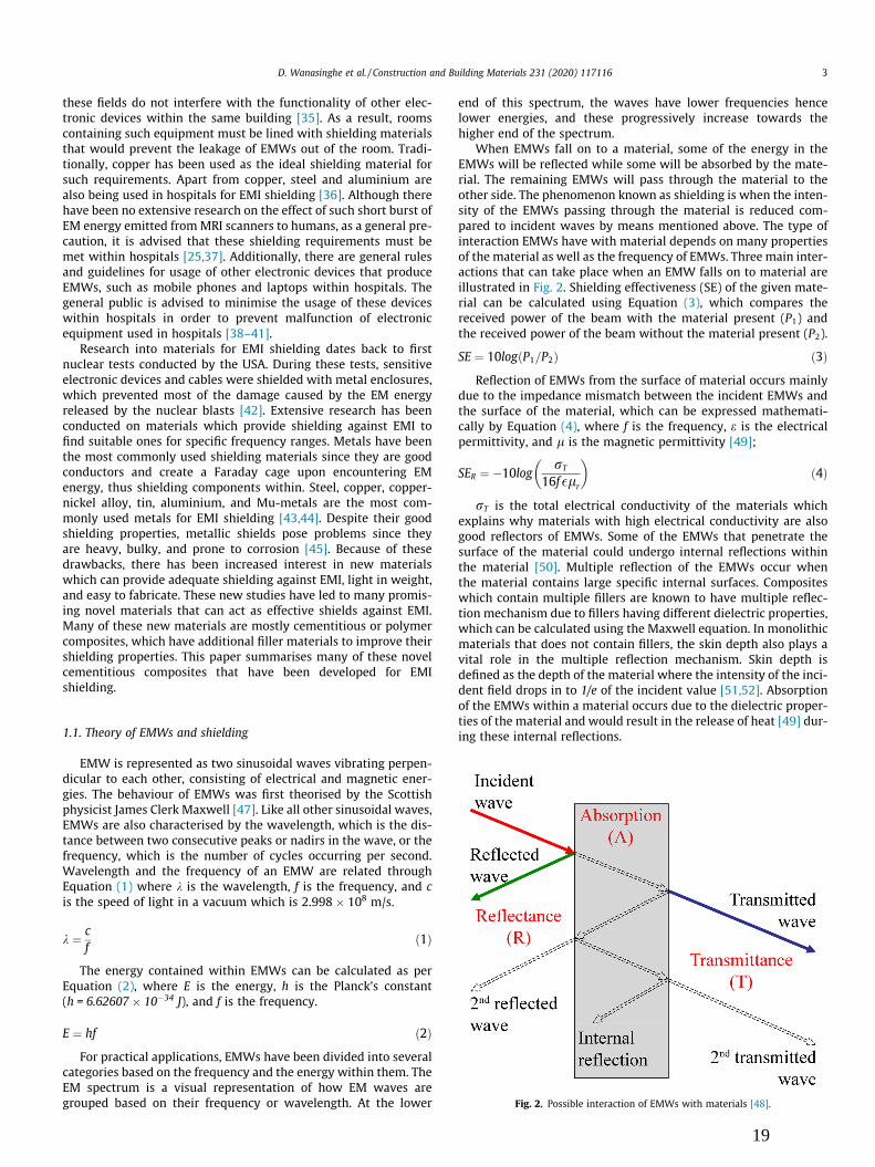
When EMWs fall on to a material, some of the energy in theEMWs will be reflected while some will be absorbed by the mate-rial. The remaining EMWs will pass through the material to theother side. The phenomenon known as shielding is when the inten-sity of the EMWs passing through the material is reduced com-pared to incident waves by means mentioned above. The type ofinteraction EMWs have with material depends on many propertiesof the material as well as the frequency of EMWs. Three main inter-actions that can take place when an EMW falls on to material areillustrated in Fig. 2. Shielding effectiveness (SE) of the given mate-rial can be calculated using Equation (3), which compares thereceived power of the beam with the material present (P1) andthe received power of the beam without the material present (P2).
SE ¼ 10logðP1=P2Þ ð3ÞReflection of EMWs from the surface of material occurs mainly
due to the impedance mismatch between the incident EMWs andthe surface of the material, which can be expressed mathemati-cally by Equation (4), where f is the frequency, e is the electricalpermittivity, and l is the magnetic permittivity [49];
SER ¼ �10logrT
16f�lr
� �ð4Þ
rT is the total electrical conductivity of the materials whichexplains why materials with high electrical conductivity are alsogood reflectors of EMWs. Some of the EMWs that penetrate thesurface of the material could undergo internal reflections withinthe material [50]. Multiple reflection of the EMWs occur whenthe material contains large specific internal surfaces. Compositeswhich contain multiple fillers are known to have multiple reflec-tion mechanism due to fillers having different dielectric properties,which can be calculated using the Maxwell equation. In monolithicmaterials that does not contain fillers, the skin depth also plays avital role in the multiple reflection mechanism. Skin depth isdefined as the depth of the material where the intensity of the inci-dent field drops in to 1/e of the incident value [51,52]. Absorptionof the EMWs within a material occurs due to the dielectric proper-ties of the material and would result in the release of heat [49] dur-ing these internal reflections.
Fig. 2. Possible interaction of EMWs with materials [48].
D. Wanasinghe et al. / Construction and Building Materials 231 (2020) 117116 3
19
There are several methods developed for the measurement ofthe SE, giving emphasis to various parameters and standards. Mostof these techniques use a vector network analyser (VNA) whichgenerates a radio frequency signal and transmit it by using anantenna. EMWs that reflect and pass through the material can bemeasured by the same VNA [53,54]. The energy within thereflected and the transmitted signal can be used to calculate theSE of the material. Four main techniques that have been developedfor the measurement of SE can be described as follows.
1.1.1. Open field methodAlso known as the free space method, this mode of measuring
the SE comprises of dual antenna setup where the EMWs are trans-mitted from one while the transmitted EMWs are captured by theother. The shielding specimen which is placed between the twoantennas should be placed 1 m, 3 m, 5 m, 10 m, or 30 m from thereceiving antenna depending upon the standard used for the SEmeasurement [50,55]. This method is known to be a very realisticform of measurement of SE since the testing conditions are verysimilar to that of practical scenarios.
1.1.2. Shielded box methodIn the shielded box method, the sample is placed in an opening
within a Faraday cage. The specimen is irradiated with EMWs fromthe antenna placed outside the box while the antenna inside mea-sures the transmitted wave energy [50]. This method suffers fromseveral drawbacks such as limitations in the range of EMWs thatcan be used and difficulty in achieving the required electrical con-tact between the specimen and the box.
1.1.3. Shielded room methodThis method has been developed to overcome the limitations of
the shielded box method but remains to be one of the most com-plicated methods of measuring the SE. It comprises of an anechoicchamber with two antennas and the sample placed between thetwo antennas. One antenna transmits the EM signal onto the spec-imen while the other measures the intensity of the signal comingthrough the specimen [50]. Shielded room method has beendescribed in MIL-STD-188-125-1 standard for the measurementof SE [46].
Another variation of the shielded room method is the reverber-ation chamber method, which has an enclosure which can be usedto measure the SE of both small and large specimens. The specimenwhich needs its SE measure is kept inside the chamber attached toa small enclosure while the chamber is irradiated with EMWs ofdifferent frequencies [56,57]. The SE can be measured by theantenna, which is placed inside the smaller enclosure. Few of thekey advantages of this method include repeatability, the abilityto use a wider range of frequency, and the ability to irradiate thespecimen with EMWs with different angles [58,59].
1.1.4. Co-axial transmission line methodCo-axial transmission line method is the most commonly used
technique for the measurement of SE due to various advantagesit provides such as the ability to measure the SE over a wide rangeof frequencies, repeatability of the testing, and the comparability ofresults tested at different facilities [60,61]. The specimen is keptwithin a sample holder while it is irradiated with EMWs fromthe VNA. Intensities of the reflected and transmitted EMWs arethen measured by the same VNA.
Since many new materials being investigated for EMI shieldingproperties are composites, it is often necessary to use other charac-terisation techniques to evaluate their mechanical and morpholog-ical characteristics. While having high SE values, materials used forEMI shielding applications are required to have sufficient strength
in order to carry physical loads applied during real-lifeapplications.
1.2. Other characterisation techniques
Apart from SE measurements, materials fabricated for EMIshielding should also undergo other characterisation techniquesto understand their morphological, compositional, mechanical,and compositional properties. Scanning Electron Microscope(SEM) and Transmission Electron Microscope (TEM) analyses arethe most commonly utilised morphological characterisation tech-niques mainly due to the high-resolution images they can provide.X-Ray Diffraction (XRD) and Energy-dispersive X-ray Spectroscopy(EDS) analyses can be used to analyse the composition of the mate-rials. XRD can be used for qualitative and quantitative analysis ofthe material and have been used for a very long time due to its reli-ability. For the characterisation of polymeric materials, FourierTransform Infrared Spectroscopy (FTIR) is the most commonlyused technique. New developments in technology have made thecharacterisation of other materials also possible by using thismethod. Tensile test, 3-point bend test, and the compressive testcan be utilised for the measurement of mechanical properties.Some of the materials, such as cementitious materials wouldrequire certain time periods such as 28 days before the finalstrength can be measured.
2. EMI shielding cementitious shielding composites
2.1. Introduction
EMI is known to cause failures within many sensitive electronicsystems on a regular basis with catastrophic losses [11]. Researchwork conducted on EM radiation and human health have shownthat EM radiation emitted from most of the electronic devicescan have a long-term adverse effect on human health [24,62].Due to such reasons, shielding from EM radiation has attracted alot of attention in the field of material development. Most of theexisting material used in EMI shielding are metals with good elec-trical conductivity. Unfortunately, these metals have high specificweights and are also prone to corrosion. While metals have beenable to satisfy shielding requirements, modernisation of electronicdevices requires more lightweight, flexible, and corrosion resistantmaterials. As a result of these requirements, there has been anincrease in the research conducted on EMI shielding of novel mate-rials. This is reflected by the number of research publications onEMI shielding materials over the past few decades. Most of thesepublications have focused on using polymers as shielding materialssince most polymers are light in weight and corrosion resistant.Some researchers have tried to formulate cementitious, wood-based, or even modified metallic materials to suit modern shield-ing needs. Naturally, cement-based materials are known to havea slight amount of conductivity owing to the ion transfer, whichdepends on the evaporable water content in the cement mixture.In this regard, the overall conductivity of cementitious materialsis known to increase by having a porous microstructure with a sig-nificant degree of interconnectivity [63]. Based on the type of fillersused to enhance the SE, cementitious composites can be broadlyclassified, as shown in Fig. 3. This paper discusses some of thenovel cementitious composites within this classification.
Concrete is one of the most commonly used cementitious con-struction material in the world which has been investigated forits electrical conductivity and EMI shielding properties. Many ofthe past research into concrete have revealed that conductivityand SE depend onmany factors, such as the type of additives, waterto cement ratio, porosity, and fillers [64]. Several publications have
4 D. Wanasinghe et al. / Construction and Building Materials 231 (2020) 117116
20

shown that the addition of steel rebar can increase the overall SE ofthe concrete since it would add to the conductivity of the compos-ite. Hyun et al. [65] have carried out several tests on concrete withand without the inclusion of rebar in order to measure their effecton the shielding effectiveness. Authors have found that concretedoes possess a very small natural shielding property, especiallyat higher frequencies owing to relative permittivity and loss tan-gent values. The addition of rebar enables the concrete to have ahigher attenuation of EMWs at lower frequencies. Further studieson the rebar and their size have yielded that with the increase ofthe rebar diameter and the decrease of the spacing between therebar, the attenuation of the EMWs and the SE of concrete increase.Additionally, a double layer rebar structure has proven to have alower transmission of EMWs than a single layer rebar structure.From these results, authors conclude that the addition of doublelayer rebar can reduce the transmission coefficient by up to 30–60 dB when compared to concrete with single layer rebar.
2.2. SE of different types of concrete
According to some of the published literature, different types ofconcrete that are already being used in the construction industryhave shown to possess a varying amount of SEs. Koppel et al.[66] have conducted experiments to measure the SE of three differ-ent concretes. Natural fibre concrete pressed plate, aerated con-crete, and high-performance concrete has been tested for their SEalong with thirteen other most commonly used construction mate-rials in this experiment. SE test has been carried out at 2.4 GHz inorder to measure how much shielding each of these materialswould provide in the Wi-Fi frequency band. Out of all the materialstested, high-performance concrete has provided the highest reflec-tion coefficient and the lowest transmission coefficient, making itthe best EMI shielding material out of the tested ones. In additionto this finding, authors have suggested that atmospheric factors,such as humidity can also affect the shielding properties of somethe materials which require further investigations. For example,authors claim that aerated concrete might be able to producehigher SE when the atmospheric moisture content is increasedbecause of the absorbed moisture within the concrete can increasethe attenuation of EMWs. Apart from high-performance concrete,authors claim gypsum board and oriented strand board can be
used in EMI shielding applications since they have shown consid-erably lower transmission coefficients.
Since the water content within the cementitious composite is afactor that can alter the SE, Chung and Kharkovsky [67] have inves-tigated how water content can affect the EMW absorption of con-crete. Additionally, authors have investigated the effect of coarseaggregates on the EMW absorption as well. While the primaryobjective of this experiment has been to measure the curing rateof concrete and mortar using EMWs, it has also provided valuableinformation into absorbance and reflection of microwaves duringthe curing period. The shielding characteristics have been mea-sured over a frequency range of 8.2–12.4 GHz. Authors haveobserved that the electrical conductivity of the concrete and mor-tar both decrease with the ageing period, which is mainly due tothe reduction of free water within the material. The rate of reduc-tion of the conductivity was observed to be different in the twomaterials and theorised to be due to the addition of aggregateswithin the concrete. The reflectivity of EMWs from the specimenshas shown similar behaviour to that of the conductivity. Whileauthors have not measured the shielding properties of materialsin details in this work, they conclude that conductivity can be usedas an effective method in measuring the curing behaviour ofconcrete.
While early research into EMI shielding materials have exploredthe possibility of using concrete as it is, Sato et al. [68] have inves-tigated the possibility of modifying the surface of the concrete wallto mitigate the EMWs and enhance the shielding capabilities. Theyhave used a triangular and sinusoidal wave-shaped structure forthe concrete walls. The effects of wave-shaped concrete walls havebeen analysed theoretically using the Finite Difference-TimeDomain (FD-TD) technique at the frequency of 2.5 GHz. To verifythe accuracy of the theoretical calculations, actual concrete speci-mens constructed with these shapes have been tested using anexperimental setup within 6–10 GHz frequency range. There havebeen slight discrepancies when the two results from the theoreti-cal calculation and the experimental setup have been compared.Authors suggest the differences might be due to the differencesof the relative permittivity, which would have occurred becauseof the possible inclusion of water within actual samples. Authorsclaim that the SE of the concrete walls can be further enhancedby adjusting the width and the depth of the grooves but suggest
Fig. 3. Broad classification of EMI shielding cementitious composites.
D. Wanasinghe et al. / Construction and Building Materials 231 (2020) 117116 5
21

extending the experiment to a three-dimensional analysis forbetter accuracy. Summary of SE produced by different types ofconcrete that has been discussed within this section is providedin Table 1.
2.3. Carbon particles based composites
Since the SE of concrete has proven insufficient to be used as aneffective barrier against EMI, the development of cementitiousmaterials has focused on the addition of filler materials into thecement mix to enhance the SE. One of the earliest experiments inusing filler materials to reflect EMWs has been conducted by Fuand Chung [69]. The main focus of the research has been to useconductive concrete as a guidance system in automatic highways.Carbon filaments having a diameter of 0.1 lm andlength > 100 lm, has been the main filler added to the mix in orderto enhance the EMW reflection properties. Different mixes contain-ing 0.5 wt%, 1.0 wt%, and 1.5 wt% of carbon filament have been cre-ated to find out the mix with best reflective properties. Authorsclaim no aggregates have been used in any of the mixes. Beforeadding to the mix, carbon filaments have been surface treated withozone gas to enhance the bonding between the filaments and thecement matrix. The SE tests have been carried out for 1 GHz fre-quency. Results from the SE tests have revealed that with theincrease of the carbon filament content, the SE of the compositesincreases. The mix with the largest SE has been the mix containing1.5 wt% carbon filament. The primary shielding mechanism hasbeen identified as the reflectivity of EMWs. Authors further claimthat the addition of carbon filaments have greatly enhanced themechanical properties of the concrete as well.
Many experiments focused on fabricating EMI shielding cemen-titious composites have looked into using fillers with high electri-cal conductivity to achieve the required level of shielding. Graphiteis known to be an excellent electrical conductor and has been usedin a variety of applications where high conductivity is sought.Hence, graphite is one of the preferred materials to be added tothe cement mix to increase the conductivity and SE. Guan et al.[70] have analysed several cementitious mixes in literature wheregraphite have been added to improve the SE. They have found thatthe SE and the electrical conductivity of mixes increase with theincrease of the graphite content. Authors claim that a 3 mm thickcementitious composite specimen containing 30 wt% graphitecan produce a SE of about 10–40 dB over the frequency range of200–1600 MHz. However, graphite being a brittle material canhave a significant impact on the overall mechanical propertieswhen added to a cement mix. Unfortunately, authors have notmentioned the change in mechanical properties that may arisedue to the addition of graphite. Analysis of another experimentalwork shows that the creation of a graphite layer on top of thecementitious composite can also increase the overall SE of thecomposite. According to details in the experiment, the graphite
coating is created by suspending graphite particles on water oralcohol. Once the water or the alcohol is evaporated, the graphitecoating is applied over the composite. One key advantage of thismethod is the increased electrical conductivity and SE of the com-posite due to the interconnectivity of graphite particles. A 4.4 mmthick coating made by using this technique has been able to pro-vide a SE of 22.3 dB at 1.0 GHz and 25.6 dB at 1.5 GHz respectively.Authors also mention that styrene-butadiene latex and silica fumecan be used to disperse graphite within the composite that wouldexpand the conducting network increasing the SE.
Guan et al. [70] have also analysed published literature wherecarbon black (CB) particles have been added to the cementitiouscomposite to increase the SE. A 10 mm thick cementitious compos-ite specimen containing 3.0 vol% CB has been able to produce a SEof 6–8 dB when tested within 2–8 GHz frequency range. Toimprove the SE of the composite, authors have fabricated anothermix containing CB and a secondary absorbent which has pushedthe SE up to 15 dB. Authors claim that the addition of the sec-ondary absorbent has decreased the conductivity of the material,improving the impedance matching between the specimen surfaceand the free space. This has resulted in a decrease in the reflectionand an increase in the absorption of EMWs. The absorbing beha-viour of the composites containing different CB content is shownin Fig. 4(a). A TEM micrograph of CB nanoparticles used in thisexperiment is shown in Fig. 7(a).
Dai et al. [71] have used high-structure CB fillers to create anEMI shielding cementitious composite with high SE. High-structure CB differs from low-structure CB mainly due to thehigher number of branching and chaining within an aggregate.Apart from the branching differences, high-structure CB also showsvery high electrical conductivity and high specific surface area.Authors have opted to use high-structure CB to fabricate a cemen-titious composite since high-structure CB is not a commonly usedfiller in the fabrication of cementitious composites even though ithas been widely used in fabricating polymer composites with highelectrical conductivity. Several cementitious mixes have been fab-ricated by varying the CB content so that their shielding propertiesand mechanical properties can be compared to the control mixcontaining 0 wt% CB. Shielding tests have been carried out for8.0–18.0 GHz and 18.0–26.5 GHz frequency ranges. Conductivitytests, which have been carried out by using the four-probe tech-nique, have shown that the conductivity of the cementitious com-posites increases with the increasing CB content. Compressivestrength, on the other hand, has decreased with the increase ofthe CB content. The compressive strength of the composite haddecreased at a rapid rate when the CB content was increasedbeyond 3 wt%. Authors theorise one possibility for the reductionin the compressive strength as the need for higher water contentin the cement mix because of the absorption of a higher amountof water by CB due to their large specific surface area. Throughoutthe entire frequency range tested, a composite containing 2.5 wt%
Table 1Summary of SE in different types of concrete.
No. Type Frequency Specimens thickness Effect of shielding References
1 Steel reinforces concrete – – The transmission coefficient approximately30–60 dB lower in double-layered rebar, thanthe single-layer
[65]
2 Natural fiber concrete pressed plate/Aeratedconcrete/High performance concrete plate,round shape/High performance concrete plate
2.4 GHz 50 mm/100 mm/13 mm reflection coefficients, �0.03/�0.11/0.38/0.35 [66]
3 Plain concrete 8.2–12.4 GHz 250 mm Varies greatly over the hydration period, anaverage value cannot be determined
[67]
4 Plain concrete 6–10 GHz 10–30 mm By adjusting the width and the depth of thegrooves, reduction of reflection andtransmission is found possible at the requiredwall thickness
[68]
6 D. Wanasinghe et al. / Construction and Building Materials 231 (2020) 117116
22

CB has shown a minimum reflectivity of �20.30 dB. Authors claimthat the loss factor of the composite has increased due to the addi-tion of CB, resulting in the increased absorption of EMWs. Absorp-tion performance (reflection loss) of fabricated composites isshown in Fig. 4(b) and (c). SEM micrograph of the cementitiouscomposite containing high-structure CB is shown in Fig. 7(b).
Xie et al. [72] have investigated the EMI SE of CB mixed compos-ite fabricated into a honeycomb structure. The CB has been coatedon to a paper honeycomb structure which then filled with gypsumplaster. The particle size of the CB that has been used for the com-posite fabrication had ranged between 30 and 50 nm. Apart fromhaving different CB contents, authors have varied the side lengthand height of the honeycombs to study the effect of the geometryparameters on shielding. EMI shielding tests have been carried outusing arched reflecting testing method over the frequency range of2–8 GHz. As expected, the results have shown that increasing theCB content yields a higher SE. Authors claim honeycombs withsmaller side length, and larger height leads to composites havingbetter SE since the EMWs tend to have a higher number of internalreflections, which leads to higher attenuation of EMWs. Eventhough this research has not fabricated a cementitious composite,the method described by the authors can be adopted in fabricatinga cementitious composite.
Yee and Jenu [73] have studied the SE and the permittivity ofcementitious composites containing fine graphite powder (FGP).Authors have fabricated cementitious composite mixes containing7.2 vol%, 9.6 vol%, and 12 vol% of FGP and compared the resultswith a control mix containing 0 vol% FGP. All the specimens hada thickness of 20 mm. The SE tests have been carried out within50–400 MHz frequency range. Results from the shielding testshave shown that the addition of FGP increases the SE of the com-posites. However, authors have discovered that addition of FGPbetween 200 and 250 MHz frequency range decreases the multiplere-reflection loss, reducing the SE of the composite. Even with thisreduction, increasing the filler content has increased the overall SEof the composite. The composite containing 12 vol% of FGP has
shown the highest SE. Authors claim the addition of FGP has notincreased the conductivity of the composite drastically hence hasnot produced a high absorption loss at lower frequencies.
In the hope of creating a cost-effective EMI shielding cementi-tious composite, Khushnood et al. [74] have used micro andnanoparticles of carbon derived from carbonised peanut and hazel-nut shells as filler materials. Raman spectrometer analysis con-ducted on both shells has revealed that the chemical compositionof both shells is almost equivalent to each other, and both shellscontain a limited amount of carbon in their structure. SEM imagesof the carbonised shells have shown smooth textures, a featurethat would minimise possible entanglement problems that mightoccur during the mixing process. Two composite mixes containing0.2 wt% and 0.5 wt% of each carbonised shell have been createdalong with a control mix containing 0 wt% of carbonised shells.The distribution of the carbon nanoparticles within the compositecan be seen in the SEMmicrograph given in Fig. 7(c). Each compos-ite has been tested within 0.2–10 GHz frequency range for their SE.As expected, SE has increased with the increase of the carbonisedshells content. At the same filler content, the composite containingpeanut shells has shown a slightly higher SE than the compositecontaining hazelnut shells. A maximum SE of 2–10 dB has beenobtained by these composites for the tested frequency range. SEvariation of composites containing the two type of carbonised nut-shells is shown in Fig. 4(d). Cost comparison with commonly usedconductive fillers have shown that these carbonised nut shells canachieve the same SE but at a fraction of the cost compared to mostcommonly used expensive fillers such as CB and carbon nanotubes.Authors mention they plan to use other agricultural wastes toinvestigate the possibility of manufacturing more cost-effectiveEMI shielding composites in the future.
Waste material collected from the palm oil industry known asthe Palm Oil Fuel Ash (POFA) is also used as a replacement forcement in cementitious composites manufacturing. POFA is classi-fied as fly ash due to its chemical composition and currently beingtreated as landfill, which causes severe environmental pollution.
Fig. 4. (a) The absorbing performance of carbon black added composite materials. 1#: 1.5 vol% CB, 2#: 3.0 vol% CB, 3#: 6.0 vol% CB, 4#: combined wave absorber [70], (b) theabsorbing performance of CB mixed cementitious composites with different concentration of CB in the frequency range of 8–18 GHz (c) 18–26.5 GHz [71], (d) SE ofcementitious composites containing carbonized peanut and hazelnut shells (CPS- carbonized peanut shells, CHS- carbonized hazelnut shells) [74], (e) EMI SE of cementitiouscomposites containing GO [76], and (f) SE of the cementitious composite with 10 wt% GO and 2 wt% SF [77].
D. Wanasinghe et al. / Construction and Building Materials 231 (2020) 117116 7
23

Studies in the literature have shown that POFA can be used as astrength addition filler in concrete. Narong et al. [75] have investi-gated the possibility of using POFA as a low-cost filler in EMI shield-ing cementitious composites. X-ray fluorescence (XRF) andchemical analyses have confirmed that the POFA used in this studyconforms to ASTM C618 standard. Different mixes of cementitiouscomposites have been fabricated by adding a varying amount ofPOFA. The SE of the mixes has been measured using a transverseelectromagnetic parallel plate method within 0.1–1.5 GHz fre-quency range. Authors have used Taguchi Grey method to optimisethe mixes further to enhance their mechanical properties, and as aresult, they have been able to achieve an increase of 45.90% in the28 days compressive strength. The optimisation technique has alsorevealed the optimum POFA content to be 20 wt%. A composite mixwith 20 wt% of POFA has been able to generate a SE of 6 dB withinthe tested frequency range. Authors claim the use of the TaguchiGrey method has resulted in improvement in the mechanical prop-erties as well as in the SE compared to original mixes in theexperiment.
As shown in equation (4), the SE of a material increase with theincrease of its electrical conductivity. Hence, many of the EMIshielding material research have focused on increasing the conduc-tivity of the specimen to achieve a high SE value. To achieve highelectrical conductivity, some researchers have used graphene oxide(GO) as a conductive filler in the fabrication of cementitious com-posites [107–108]. Apart from having high electrical conductivity,GO particles are known to have a large specific surface area. Addi-tionally, the presence of defects and groups within GO particlescan attenuate EMWs by increasing the number of internal reflec-tions. Due to these many advantages, Zhao et al. [76] have usedGO powder to fabricate a conductive cementitious composite forEMI shielding applications. In this research work, graphite powderhas been subjected to modified Hummer’s method to obtain therequired GO. Obtained GO has been added to the cement mix andthen ultrasonicated to disperse them within the cement matrix.Several composite mixes have been fabricated in this manner byvarying the GO content. Resultant composites have been kept for28 days to achieve the required mechanical strength. After speci-mens have been cured for seven days, they have been subjectedto EMI SE tests within 8.2–12.4 GHz frequency range. Apart fromthese characterisation techniques, the specimens have been sub-jected to SEM and XRD analyses as well. The SEMmicrograph show-ing the emerging of hydration crystals in GO/cement composite isshown in Fig. 7(d). Mechanical tests have revealed the compressiveand the flexural strength of the specimens increased with the age-ing time similar to that of the control mix containing 0 wt% GO.However, the compressive and the flexural strength after 28 daysof the composite containing 0.08 wt% GO has shown a slightlyhigher value than the control mix, indicating the addition of theGO had a positive impact on the mechanical properties. The EMISE of composites shows an increasewith the increase of the GO con-tent up to 0.08 wt% then recedes to a lower value than the controlmix, as shown in Fig. 4(e). Unfortunately, authors have not providedpossible reasons for such fluctuations of SE of the composites.
Following the finding that GO can improve the SE of cementi-tious composites, Mazzoli et al. [77] have tried to enhance the SEof the cementitious composite by adding GO with metal fibres.By the combination of these fillers, authors have expected to obtainan excellent conducting network within the composite that wouldenhance the EMI SE. The experiment has used GO microparticlesmixed in with brass coated steel fibres (SF) as filler materials. Tocheck the effect of each filler, different mixes containing none ofthe conducting fillers, GO only, SF only, and GO and SF has beenfabricated and tested for their mechanical and EMI shielding prop-erties. Distribution of GO particles within the concrete mix isshown in Fig. 7(e). The compressive strength of the mixes contain-
ing GO has not seen an increase that was observable in previous lit-erature containing GO. Authors suggest that the loss of planarity ofthe particles during the mixture preparation due to their consider-able large size may have caused the compressive strength not toimprove as expected. On the other hand, the addition of SF hasimproved the flexural strength of the composites. EMI shieldingproperties of the mixes have been tested within 0.8–7.8 GHz fre-quency range. Results have shown that the SE of the compositesincreases with the increase of GO content. However, a more pro-found effect on SE is generated when SF and GO are added to thecomposite mix. Hence, the composite containing GO and SF hasshown the best SE. Authors claim the composite containing 10 wt% GO and 2 wt% SF has a stable SE between 40 and 50 dB overthe tested frequency range, as shown in Fig. 4(f). The high SEachieved by this composite is due to the extension of the conduc-tive network within the composite because of the synergetic effectof the two fillers which has resulted in increasing the number ofinternal refraction and higher attenuation of EMWs.
While some researchers have focused on fabricating EMWreflecting composites, others have tried to maximise the absorp-tion and minimise the reflection of EMWs. Mostly in indoor envi-ronments, it is crucial to minimise the reflection of EMWs sincereflection is most likely in such environments, and it can causeadditional interference in vulnerable devices. For the EMWs to beabsorbed by a material, it is necessary for the waves first to pene-trate the material. However, most of the cementitious compositeshave a very compact structure making it difficult for the EMWs totravel inside the composite. The composite needs to have a certainamount of porosity to make sure the EMWs can go into the mate-rial. Lv et al. [78] have tried to maximise the EMW absorption ofcementitious composites by increasing the porosity of the compos-ite. Authors have used hollow glass microspheres (HGM) to createthe porous structure necessary for the penetration of the EMWs.However, when the porosity of the composite is increased, thestrength of the composite can be decreased. Therefore, thereshould be an optimum amount of porosity within the compositewhile maintaining sufficient strength to carry the applied load.To maximise the absorption of the EMWs while maintaining suffi-cient strength, authors have used graphene nano-platelets (GN)along with HGM in the composite mix. Several composite mixescomprising of the two fillers have been fabricated and tested fortheir SE and mechanical properties. The SEM analysis carried outto observe the morphology of the composite has shown a uniformdistribution of GN and HGM within the concrete. The SE test hasbeen carried out by using an arched anechoic chamber setup forthe frequency range of 2–18 GHz. To analyse the effect of thicknesson the SE, specimens with thicknesses of 10 mm, 20 mm, and30 mm have been cast and tested by using the same test. Mechan-ical test results show that the compressive strength of the mixesvaries with the addition of filler, but authors have failed to estab-lish a relationship with the filler content and the compressivestrength of the composites. Variation of the EMI SE of differentcomposite mixes is shown in Fig. 8(a).
From this graph, it can be seen that the absorption of the spec-imens undergoes improvement as the HGM content is increased.Variation of the GN has shown that there is an optimum level ofGN that can be added to mix to achieve maximum absorption ofEMWs after which additional GN would result in an adverse out-come for the SE. Analysis of the variation of the thickness of spec-imens has shown that the absorption of the EMWs cannot becontrolled only by changing the thickness and depends on manyfactors, including the frequency of the EMWs. From obtainedresults, authors have concluded that for a composite containing40 vol% HGM and 0.2 wt% GN the optimum thickness would bebetween 20 mm and 30 mm if it is being subjected for EMWswithin the frequency range of 2–18 GHz.
8 D. Wanasinghe et al. / Construction and Building Materials 231 (2020) 117116
24

Summary of composite mixes containing carbon powder thathas been analysed in this section is provided in Table 2. Reflectionloss of several specimens is plotted together for comparison inFig. 5. For this comparison, maximum reflection loss shown byeach composite mix within the tested frequency range has beenplotted. The composite containing GN and HGM has shown threesharp peaks of �34, �37, and �20 dB at about 6, 10.5, and15 GHz respectively. �37 dB is the maximum reflection loss shownby any composite containing carbon particles. However, the samecomposite does not maintain the reflection loss throughout theentire frequency range. Composite with 0.5 wt% carbonised peanutshells which contain 93.77% carbon, has shown the minimumreflection loss, which is about 0 to �7 dB. Composites containing0.5 wt% CB has a very similar reflection loss characteristic to thatof the composite with CPS, which leads to the conclusion that acementitious composite with carbon particles alone can show onlya limited increase in their reflection loss. Addition of higher per-centages of carbon particles without another filler has not beeninvestigated by authors since previous literature have shown thata high amount of carbon particles in the cementitious compositescan increase the brittleness and the cost of the composites.Composites with CPS and carbon particles show an increasing SE
with the increase of the frequency up to 18 GHz and starts todecrease again.
Addition of a secondary absorber along with CB can improve thereflection loss characteristics of the composites. This compositewith CB and secondary absorber shows two reflection loss peaksof about �18 and �14 dB at 4 and 6 GHz respectively. In general,the reflection loss of the composite with CB and secondary absor-ber is higher than composite with CPS. However, the addition ofthe secondary absorber has not helped to maintain a uniformreflection loss within the tested frequency range. Altering thegeometry of the composite has shown an effect on the reflectionloss as the composite with CB and honeycomb geometry showsslightly higher reflection loss than the flat specimen. The honey-comb with a height of 9 mm has shown two reflection loss peaksof about 18 and 16 dB at 3 and 7 GHz. Increased multiple reflec-tions EMWs undergo when they encounter the hexagonal honey-combs has been the main reason for the increased reflection loss.
Total SE of three composite mixes described in this section isplotted in Fig. 6. The comparison shows the addition of only carbonparticle to cementitious composite imparts only a very small SE.Carbonised peanuts and graphene oxide particle added compositesshow very similar behaviour with the increasing frequency.
0 2 4 6 8 10 12 14 16 18 20 22 24 26 28-40
-35
-30
-25
-20
-15
-10
-5
0
3 vol% CB to SiO2 + Secondary absorber [70] 0.5 wt% CB [71] 0.5 wt% CB [71] 9 mm honeycomb height + 0.6% CB [72] 0.5% CPS [74] 0.2% GN + 60% HGM [78]
Ref
lect
ion
loss
(dB
)
Frequency (GHz)
Fig. 5. Variation of reflection loss of carbon particle based cementitious composites.
0 1 2 3 4 5 6 7 8 9 10 11 12 130
5
10
15
20
25
30
35
40
45
50
SE (d
B)
Frequency (GHz)
0.5% CPS [74] 0.08 wt% GO [76] 2 wt% SF + 10 wt% GO [77]
Fig. 6. Total SE of carbon particle based cementitious composites.
Table 2Summary of carbon powder based cementitious composites.
No. Shielding material Frequency Specimensthickness
Effect of shielding References
1 Carbon filaments 1 GHz 3.6–4.4 mm 29 dB higher than thetransmissivity
[69]
2 Carbon/Metal/Ferrite/Fly ash 2–8 GHz/2.45 GHz/75–100 GHz/1.0–1.5 GHz
10 mm/-/30 mm/4.3 mm
6–8 dB/8 dB/7–9 dB/4 dB [70]
3 Carbon black 8.0–18.0 GHz and 18–26.5 GHz 30 mm Reflectivity < -20.30 dB and < -10 dB
[71]
4 Carbon black (CB) coated paper honeycomb 2–8 GHz Variablethicknesses
Reflection loss ~ 10 dB [72]
5 Graphite Fine Powder 50 MHz–400 MHz 20 mm 2.4 dB additional shielding at360 MHz
[73]
6 Carbonaceous nano/micro inerts [peanut shell andhazelnut shell]
0.2–10 GHz – 2–10 dB [74]
7 Palm Oil Fuel Ash (POFA) 0.1 and 1.5 GHz 120 mm 6 dB [75]8 Graphene oxide (GO) 8.2–12.4 GHz 5 mm 11–16 dB [76]9 graphene oxide particles + straight brass-coated steel
fiber0.8–7.8 GHz 2.5 m and 0.8 m 25–50 dB [77]
10 Graphene nano-platelets (GN) and hollow glassmicrospheres (HGM)
2–18 GHz 10, 20, and 30 mm �8.2 dB [78]
D. Wanasinghe et al. / Construction and Building Materials 231 (2020) 117116 9
25

Composite with CPS shows an overall SE of about 2–10 dB within0.2–10 GHz frequency range. The composite with GO shows anoverall SE of about 11–15 dB within 8.2–12.4 GHz frequency range.Both composites with CPS and GO shows an increasing SE with thefrequency. However, given that composite with CPS has 0.5 wt% ofparticles and the composite with GO contains only 0.08 wt% of par-ticles, it can be concluded that GO can impart larger SE than carbonparticles in cementitious composites. The third composite with2 wt% SF and 10 wt% GO has shown a SE, which is almost six timeshigher than the other two composites. The superior SE of the thirdcomposite is created due to the synergetic effect of steel fibres andcarbon particles, which helps to extend the conducting networkwithin the composite. A SE of 33–48 dB has been generated bythe composite with SF and GOwithin 0.8–8.4 GHz frequency range.The composite has been able to maintain its high SE throughoutthe tested frequency range. From all these results it can be con-cluded that addition of carbon particles alone is insufficient to cre-ate an adequate SE within a cementitious composite and additionof secondary fillers such as steel fibres is necessary to achieve anadequate SE.
2.4. Carbon fibre based composites
As mentioned in the previous sections, many of the researchershave used carbon-based fillers for the fabrication of compositesrequiring high electrical conductivity. Out of these carbon-basedfillers, carbon fibres (CF) have been used in composite fabricationfor several decades, mainly due to their lower cost of manufactur-ing compared to other filler materials such as carbon nanotubes. Tomeasure the impact of CF, Zhang and Sun [79] have fabricatedcementitious composites consisting of the varying amount of CF.Moreover, test results that were obtained for CF mixed compositeshave been compared with composites containing steel fibres. Eachcomposite has been fabricated by using the mould cast method.After the composite has been cast, they have been left for 28 daysto achieve their strength. Specimens have been tested for the SE byusing the shielded box technique for the frequency range of 8–18 GHz. SE test results have shown that SE increases with theincrease of CFs and steel fibres in each composite type. However,the reflectivity of EMWs from the two composites does not showsimilar behaviour to that of the overall shielding. When the steelfibre content is increased in the composite, the reflectivity ofEMWs increases, but when the CF content is increased, it reachesa maximum reflection value and gradually decreases. Authorsclaim this behaviour is mainly because of the impedance mismatchthat would occur when the CF fraction is increased. The maximumamount CFs added to the composite has been limited to 1% due totheir cost. The overall SE of the two composites with the fibre frac-tion is shown in Fig. 8(b) and (c). From these results, it can be seenthat with the increase of the fibre content of both fillers, the overallSE is increased. Authors suggest that the addition of a secondarywave absorber, such as ferrite would be able to increase the overallSE even further.
While there has been an increased number of research on EMIshielding cementitious composites in the past few decades, onlya very small number of experiments have been conducted on thesecomposites when subjected to environmental conditions. Sincemost of the cementitious composites are used in outdoor applica-tions, Wang et al. [80] have studied how the SE of cementitiouscomposites containing CFs varies with freezing and thawing cycles.The main reason behind this research has been to understand howthe SE of CF containing cementitious composite varies when itexperiences expansion and contraction due to being exposed tobelow freezing temperatures during the winter and high tempera-tures during the summer. Moreover, when cementitious compos-ites experience such temperature fluctuations, there is a
possibility of crack development in the composite that would leadto an increment of moisture content within the composite. Both ofthese factors can result in a change in the mechanical propertiesand SE of the composite. For their experiment, authors have usedcementitious composites containing 0.2%, 0.4%, 0.6%, and 0.8%CFs. SEM micrograph showing the distribution of the CFs withinthe fabricated composites is given in Fig. 7(f). Each of the fabricatedcomposites has been subjected to 50 freezing, and thawing cyclesto study their effect and results have been compared with theresults of the control mix which contained 0% CFs which hasundergone the same number of freezing and thawing cycles. SEtests have been carried out within 2–18 GHz frequency range.Results obtained from SE tests have revealed that the freezingand thawing does not change the SE when there is no CF withinthe composite. Regardless of being subjected to freezing and thaw-ing, the SE of composites has increased with the increase of the CFcontent. Additionally, authors have observed that the porosity ofthe composite decreases with the increase of the CF content butstart to increase when the CF content is 0.8%. Freezing and thawingof the composites containing CFs have shown that after compositeshave undergone these cycles, the EMW reflection of the compositesincreases while the absorption decreases at high frequencies. Vari-ation of the absorption loss of the composite containing 0.8% CFbefore and after the freezing cycles is shown in Fig. 8(d). After ana-lysing all the test results, authors conclude that CF can be added tocementitious composite undergoing freezing and thawing toenhance composite’s SE and mechanical properties. However, CFcontent should not be increased beyond the optimum level as itis detrimental to the composite.
Addition of CF has shown to increase the SE of cementitious com-posites but below the required values in industrial standards. Toovercome this limitation, some researchers have combined a sec-ondary filler with CF to boost the SE of the composite. Ferroferricoxide (Fe3O4) is such an additive that has been mixed in with CF tocreate superior EMI shielding composites. Fe3O4 is a form of ironoxide that occurs naturally as magnetite which possesses soft mag-netic properties [81,82]. Additionally, ferroferric particles are alsoknown to have high surface energy and a large specific surface area.Particles of Fe3O4 can be added to cementitious composites to pro-vide shielding against EMI and to increase the strength. Liu et al.[83] have researched the effect of CF along with Fe3O4 on the SE ofcementitious composites. Fe3O4 nanoparticles prepared by asolvothermal method with manually cut CFs having lengthsbetween 3 and 5 mm have been used for the fabrication of compos-ites. Several composite mixes have been fabricated using 1 wt%,3 wt%, and 5 wt% of the particles while maintaining the CF contentat 0.4%. Fabricated specimens have been subject to SEM, XRD, andSE characterisation to find out the distribution of fillers within thecomposite and amount of shielding the composites could providewithin 8.2–12.4 GHz frequency range. The thickness of the speci-mens subjected to SE tests has been7 mm. SEM images of specimensobtained at different magnifications are shown in Fig. 14(a) and (b).Images clearly show the distribution of CFs within the composite.Fe3O4 particles are also visible in the SEM images as small flakes.Overall, SEM images confirm that the CFs and Fe3O4 particles havebeen distributed well within the composite. SE results have shownthat with the increase of the Fe3O4 content, the SE of the compositesincreases. The composite containing 5% Fe3O4 has been able to pro-duce a maximum SE of 29.8 dB within the measured frequencyrange with the absorption being the main shielding mechanism.EMI shielding effectiveness of fabricated composites containingvarying amount of Fe3O4 nanoparticles is shown in Fig. 8(e). Authorsbelieve the synergetic effect, illustrated in Fig. 9, of the two fillers, isthe main reason for the enhanced SE of the composite. The EMWsentering the composite undergoes a high number ofmultiple reflec-tions and scattering due to the combination of the fillers, increasing
10 D. Wanasinghe et al. / Construction and Building Materials 231 (2020) 117116
26

the SE. Authors claim that this type of composite can be investigatedfurther to have even better SE.
Details of cementitious composites containing CFs discussedwithin this section is provided in Table 3. Comparison of the com-posites consisting of CF and also a composite with steel fibres isshown in Fig. 10. Composite with 1% CF has shown a SE of about30–45 dB within the tested frequency range, and its SE has beenincreasing with the frequency. Comparatively the composite with0.4% CF and ferrite has shown a SE which is about half of that ofthe composite with 1% CFs. Even though ferrite is known toincrease the SE of cementitious composites, it can be seen that aconsiderable amount of CF is necessary to impart high SE in these
composites. However, the addition of higher percentages of CFincreases the overall cost of the composite. The composite withsteel fibres has been able to generate a SE of about 55–70 dB withinits tested frequency range. The SE of the composite with steel fibresis almost twice the SE of the composite with CF. one reason for theincreased SE of steel fibre composite is the higher percentage of fil-lers, which is 3% compared to 1% CF in the other composite. Thehigh cost of the CF has been the main reason to limit the amountof them added to the composite. Findings from these works canbe used for future experiments where a higher percentage of CFalong with other fillers to cement mix to create composites withhigher SE.
Fig. 7. Microstructure of several EMI shielding concrete (a) TEM micrograph of graphite to be added to cement mix [70], (b) SEM micrograph showing CB within the concretemix [71], (c) SEM micrographs of cement mix with carbonized nanoparticles [74], (d) SEM image of GO within cement mix [76], (e) SEM image showing GO microparticlesdistributed with cement mix [77], (f) SEM image of CF dispersed within cement [80].
Fig. 8. (a) Reflection loss characteristics of cementitious composites containing GN and HGM [78], (b) SE of steel fibre reinforced cementitious composites, (c) SE of carbonfibre reinforced cementitious composites [79], (d) Variation of the absorption loss of the composite containing 0.8% CF before and after the freezing cycles [80], and (e) EMIshielding effectiveness of composites containing CF and Fe3O4 nanoparticles (0%, 1%, 3%, and 5%) [83].
D. Wanasinghe et al. / Construction and Building Materials 231 (2020) 117116 11
27

2.5. Carbon nanotube-based composites
A carbon nanotube can be viewed as a roll-up of graphene layerinto a tubular form. If the tube consists of only one such structure,it is known as a single-walled carbon nanotube (SWCNT). Com-pared with SWCNT, multi-walled carbon nanotube (MWCNT) canbe seen as a tube comprising of several rolled up graphene layers[84]. MWCNTs have been increasingly used in many of the com-posites investigated for SE owing to their extremely high electricalconductivity. Results from most of the composites with MWCNTs
have shown that there is a promising future for these compositesin EMI shielding applications. Hence, increasing the volume frac-tion of MWCNT increases the overall SE of the composite. However,one of the critical limiting factors for using carbon nanotubes as afiller in composite fabrication has been their extremely high man-ufacturing cost.
One of the earliest research in MWCNT/cementitious compositefor EMI shielding has been conducted by Micheli et al. [85], whereMWCNT in powder form has been added to the cement mix to fab-ricate the composite. The primary objective of their experimenthas been to fabricate a cost-effective composite that would provideadequate shielding within the mobile frequency band of 0.8–8 GHz. In their research, 3 cm thick composite specimens contain-ing 0 wt%, 1 wt%, and 3 wt% of MWCNTs have been fabricated andtested for SE using the shielded box method. SEM image of the fab-ricated composite showing the conductive filler is shown in Fig. 14(e). The fibrous appearance of the SEM image indicates the distri-bution of MWCNTs within its structure. The SE of the compositeshas increased with the increase of the conductive filler content,as shown in Fig. 12(a). The SE of the composite having 3 wt%MWCNTs has been able to produce a SE about 10–35 dB withinthe tested frequency range, which is the largest SE out of all thefabricated mixes.
Taking a step further from their previous research authors havefabricated an EMI shielding cementitious composite for 1.7–2.6 GHz frequency range [86]. In this experiment, authors haveused a layered composite, as illustrated in Fig. 11. One of the mainreasons for the fabrication of a layered composite has been toreduce the cost of fabrication by cutting down the MWCNT con-tent. Two composites have been fabricated in this manner, onecontaining 1 wt% MWCNTs (M2) and the other containing 3 wt%MWCNTs (M3). High-resolution SEM micrographs, shown in
Table 3Summary of SE in carbon fibres based cementitious composites.
No. Shielding material Frequency Specimensthickness
Effect of shielding References
1 Steel fiber/carbon fiber/synthetic polyvinylalcohol (PVA) fiber
8–18 GHz 30 mm 30–50 dB/20–40 dB/reduced with fiber fraction [79]
2 Carbon fiber 2.0–18.0 GHz 10 mm �12.5 dB to �4.9 dB After freezing–thawing cycles, thereflectivity increases
[80]
3 Fe3O4 nanoparticles/CF 8.2–12.4 GHz 7 mm 20–27 dB/reflection 2–2.5 dB [83]
2 3 4 5 6 7 8 9 10 11 12 1325
30
35
40
45
50
55
60
65
70
3% steel fiber [79] 1% CF [79] 0.4% CF + 5% Fe2O3[83]
SE (d
B)
Frequency (GHz)
Fig. 10. Comparison of overall SE of carbon and steel fibres based cementitiouscomposites.
Fig. 9. Possible interaction of EMW and cement composite containing CF and Ferroferric oxide nanoparticles [83].
12 D. Wanasinghe et al. / Construction and Building Materials 231 (2020) 117116
28

Fig. 14(c) and (d), taken from the two composites show the disper-sion of the nanotubes within the cement matrix. Image of M2 spec-imen show clustering of the nanotubes while the image of M3shows the well-dispersed MWCNTs making up a conductive net-work. Hence, from the morphological characterisation, it can beconcluded that the electrical conductivity and the SE could be highin the M3 composite due to the formation of the conductive net-work. SE test has been carried out using a waveguide apparatusand shielded box method for the frequency ranges of 0.75–1.12 GHz and 1.7–2.6 GHz. Apart from actual measurements ofthe SE, authors have relied on a mathematical model to predictthe SE of the composites as well. When shielding results were anal-ysed, authors have found that a 30 mm thick M3 specimen had thehighest SE, which has reached a maximum of 80 dB at 2.6 GHz.Overall SE of the same specimen within the tested frequency rangehas been about 50 dB, as shown in Fig. 12(b) [87]. This SE isclaimed to be a very high value by authors for a cementitious com-posite containing MWCNTs since SE of the composite with thesame filler in literature have recorded lower values. Authors claimSE values obtained for these composites could be further improvedby utilising a nanoparticle-based secondary EMW absorber thatcould be integrated into the composite. However, authors havenot mentioned the variation of the mechanical properties of thefabricated composites.
Even though MWCNT is an excellent conductor, SE generated bycomposites with only these fillers is insufficient compared to stan-dards in practice. In order to enhance the SE of cementitious com-posites with MWCNTs, the addition of a secondary filler has beenresearched in many literature. In one of such experiment, Namand Lee [88] have created several cementitious composite speci-mens by varying the fly ash (FA) and silica fume (SF) content whilekeeping the MWCNT content at 0.6%. Prior research done on SF andMWCNTs has shown that SF is a good dispersion agent of MWCNTs.
This has been the primary purpose for the addition of SF in thisexperiment. The composite specimens have been fabricated byreplacing cement with 0%, 25%, 50%, and 75% of fly ash. In eachcomposite mix, the SF content has been varied by 0 wt%, 10 wt%,20 wt%, and 30 wt%. Each mix has been cast on plastic moulds hav-ing the dimensions of the coaxial transmission line used in SE test-ing. For all the specimens, SE has been tested within 1–18 GHzfrequency range. Apart from SE characterisation, specimens havebeen subjected to SEM for morphological analysis and EDS foridentification of elements within the composite. SEM micrographof the composite containing 20 wt% SF and 75% FA is given inFig. 14(f) which shows the distribution of MWCNTs mixed withother additives. EDS analysis has been able to identify componentswhich are typically present in cementitious composites. The com-posite containing 20 wt% SF and 75% FA has been able to generatethe maximum SE out of all the composite mixes, which is about 5–55 dB as shown in Fig. 12(c). Authors state that these findings cor-relate well with values in literature. Furthermore, authors theorisethat the MWCNTs distribute optimally at this SF content, increas-ing the SE of the composite. One of the constituents in FA isFe2O3, which is a soft magnetic material that could enhance theSE of a composite when added as a secondary additive. As a resultof the FA replacing cement in this experiment, the SE has increasedwith the increasing FA content. From this work, it is clear thatproper distribution of MWCNTs combined with secondary EMWabsorber could enhance the SE of the composite. Summary of theSE provided when different forms of carbon nanotubes are addedto cementitious composites is provided in Table 4.
Summary analysis of cementitious composites containing CNTsplotted in Fig. 13 clearly shows that the increase of the CNT contentcan increase the SE of the composites. Composite with 0.6 wt%MWCNTs, silica fumes, and fly ash fabricated by Nam and Lee intheir experiment work has the lowest SE out of all the specimens.Throughout the tested frequency range, it has shown a SE of 1–55 dB. All the specimens show an increasing SE with the increasingfrequency. Both experiments conducted by Micheli et al. having3 wt% MWCNTs in the composite shows slightly higher SE thanthe composite fabricated by Nam and Lee. Composite fabricatedby Micheli et al. have shown a SE of 10–35 dB within the testingfrequency range. Even though MWCNT is an excellent conductor,its high-cost limits the amount that can be added to the composite.To overcome this problem, Micheli et al. have fabricated a layeredcomposite with 3 wt% of MWCNTs. Since it was constructed to be alayered composite, it has been able to produce a SE of about 60–80 dB. Apart from the absorption of EMWs from the composite,the change in the impedance from layer to another would havecontributed to higher SE since it can result in higher multiplereflections within the composite. From the comparison, it can beconcluded that out of the analysed composites containingMWCNTs, the layered composite is the best composite for EMI
Fig. 12. (a) Variation of the SE of the fabricated specimens with the CNT content [85], (b) Variation of EMI SE of M3 specimens with different thicknesses [87], and (c) EMI SEof composites containing 20% SF and varying amount of FA [88].
Fig. 11. Three-layered cementitious composite having MWCNT [86].
D. Wanasinghe et al. / Construction and Building Materials 231 (2020) 117116 13
29

shielding. For future experiments, multi-layered composites withhigher CNT contents can be explored for their SE.
2.6. Particle-based composites
Many experimental results in literature have shown that Fe3O4
particles can enhance the SE of cementitious composites. However,the SE of the composite also depends on the distribution of the par-ticles throughout the entire composite. Which means there shouldbe an effective method to distribute the particles within the entire
matrix to obtain a high SE from the composite. To minimise thisproblem, He et al. [89] have used nano-Fe3O4 fluids to fabricatecementitious composite for EMI shielding. Co-precipitationmethod has been used to obtain the Fe3O4 liquid used in thisexperiment. The prepared liquid has been mixed into the cementmix with the other constituents, cast, and left for 28 days untilthe required mechanical strength is achieved. The amount ofFe3O4 present in the composite mixes has been varied by 3 wt%,5 wt%, and 7 wt% to assess its impact on SE. EMI shielding proper-ties of these specimens have been tested using the arched testingmethod for the frequency range of 8–18 GHz. Results from theshielding tests have shown that the absorption of EMWs is the pri-mary form of shielding in these composites. Out of the differentcomposite mixes fabricated one containing 5 wt% Fe3O4 has shownthe best SE throughout the entire frequency range. Comparison ofthe results obtained in this experiment with literature values hasbeen carried out to assess the impact of using liquid Fe3O4 insteadof its powder form. The reflection loss values from the comparisonhave shown that the liquid form of Fe3O4 has far superior SE com-pared to their traditional powder counterparts, as shown in Fig. 15(a). Authors claim this could be because Fe3O4 can disperse wellwithin the entire mix since it is already in liquid form whereas dis-persion would be difficult if it were in powder form. EDS tests con-ducted on the specimens have shown that Fe3O4 is distributed wellwithin the entire composite. Authors also claim that the nano-Fe3O4 magnetic fluid has accelerated the hydration of the cementi-tious composites leading to better early age compressive strength.
Apart from creating high SE, one of the critical challenges in fab-ricating EMI shielding cementitious composites is to make it costeffective since most of the high conductive fillers that are used inthese composite fabrications are expensive, increasing the entire
Table 4Summary of the SE in carbon nanotube-based cementitious composites.
No. Shielding material Frequency Specimens thickness Effect of shielding References
1 Carbon nano tubes (MWCNT) 0.8–8 GHz 30 mm 15 dB around 2 GHz and up to 30 dB at 8 GHz [85]2 Carbon nano tubes 2.6 GHz 25 � 12 cm2/
11 � 5.5 cm212 dB (3 cm thick) 80 dB (30 cm thick) [86]
3 Carbon nanotubes 1.7–2.6 GHz
5 cm 60–80 dB [87]
4 Multi-wall carbon nanotube (MWCNT) and fly ash (FA) 1–18 GHz 10.0 mm �8.0~–57.1 dB [88]
0 2 4 6 8 10 12 14 16 180
10
20
30
40
50
60
70
80 3 wt% MWCNT [85] 3 wt% MWCNT [86] 3 wt% MWCNT + concrete layered [87] 20 wt% SF + 75% FA[88]
SE (d
B)
Frequency (GHz)
Fig. 13. Comparison of overall SE generated by carbon nanotube-based cementi-tious composites.
Fig. 14. (a) and (b) SEM images of the cementitious composite containing CF and Fe3O4 particles [83], High magnification SEM images of 1 wt% (c) and 3 wt% (d) MWCNTreinforced material bulk morphology [86], SEM images showing the microstructure of (e) conducting concrete containing MWCNT [85], (f) composite containing MWCNT[88], and (g) SEM micrograph of the cementitious composite containing 40% EAFS [90].
14 D. Wanasinghe et al. / Construction and Building Materials 231 (2020) 117116
30

cost of the composite. To overcome this drawback, severalresearchers have tried to enhance the SE of the composite whiletrying to keep the fabricating cost low by using more cost-effective fillers. In one of these experiments, Ozturk et al. [90] haveinvestigated the possibility of using electric arc furnace slag (EAFS)in the fabrication of cementitious composite for EMI shielding.EAFS is a by-product that is created in the steel production. Analy-sis conducted in previous literature has shown that EAFS has therequired chemical and physical characteristics to be used as anaggregate in the fabrication of cementitious composites. Authorshave chosen to use EAFS fine aggregates, having an average diam-eter of 4 mm in their research. Six different mixes containing 10%,20%, 40%, 60%, 80%, and 100% EAFS replacing sand have been cre-ated along with a control mix for comparison. The flexural andcompressive strength of the composite has been measured after7, 14, and 28 days. Morphological characterization has been carriedout using an SEM analysis. SE of each composite has been mea-sured using the open space method in 3–18 GHz frequency range.Mechanical property analysis has shown that all the mixes havebetter flexural and compressive properties than the control mix.However, mechanical properties show an increase with theincreasing EAFS content up to 40% and reduce thereon. The mixcontaining 40% slag has shown an increase of 30% in its compres-sive strength compared to the control mix. SEM image obtainedfor the mix containing 40% slag is shown in Fig. 14(g). This imageshows how the slag particles are distributed within the cementmatrix, minimizing the empty space within the composite. Authorsbelieve the inclusion of slag in the cement mix has resulted in abetter interlock between the cement paste and the slag granules.SE tests on the composites have shown that the SE increases withthe increasing slag content with the mix containing 100% EAFShaving the largest SE as shown in Fig. 15(b). The mix having theoptimum mechanical properties has shown an overall SE of about15–20 dB within the tested frequency range. Authors theorize thatthe high SE obtained when the slag content is increased mainly dueto the high iron content within the slag and better interlockbetween the slag and the cement paste. Authors believe that thesecomposites could be used for potential EMI shielding applicationswith further improvements.
In some of the literature focused on fabricating EMI shieldingcementitious composites, authors have reported an observabledrop in mechanical properties. The presence of a porousmicrostructure, which helps the attenuation of the EMWs andincreases the SE is the main reason for this reduction. To overcomethe deterioration of mechanical properties in EMI shielding com-posites, Lu et al. [91] have opted to use calcined clay pellets con-sisting of nano-TiO2 powder. For additional SE, another mixcontaining the clay aggregates and 30 wt% manganese zinc ferritepowder has also been investigated. Authors have used two refer-ence composite mixes consisting of gravel aggregates and haydite.
SE tests of specimens have been carried out in an anechoic cham-ber within 8–18 GHz frequency range. Evaluation of the mechani-cal properties has shown the composite with the gravel aggregateshas the best compressive strength while the least compressivestrength has been reported by the composite with the haydite.Composite consisting of clay/nano-TiO2 aggregates has shown amoderate 28-days compressive strength, which is higher thanthe minimum required value in the industry. The SE has been high-est in the composite consisting of clay/nano-TiO2 and manganesezinc ferrite powder. This composite has been able to show a reflec-tion loss of about �9 to �12 dB. Authors believe the improvedmagnetic properties of the composite imparted by the addition offillers is the reason for its improved SE. The composite containinggravel aggregates has shown the lowest SE. Composite with hay-dite has shown the second lowest SE. Variation of the SE of eachcomposite containing different fillers is shown in Fig. 15(c).Authors believe the porous structure of haydite may have givenbetter SE to that composite compared to the composite with gravelaggregates.
Findings in the literature on powder mixed cementitious com-posites have shown promising results in having a good SE. In anattempt to enhance the SE of powder mixed cementitious compos-ites, Pretorius and Maharaj [92] have experimented in using ferri-magnetic MnZnFe2O4 powder and MnO4 magnetic powder. Severalspecimens have been fabricated by varying the ferrimagnetic andmagnetic powder content in composite mixes. Authors haveattempted to fabricate a cementitious composite suitable forindoor applications and aimed at shielding mobile frequency bandsand Wi-Fi frequency band. For the SE measurement authors haveused the open field measurement technique within the frequencyranges of 824–894 MHz, 890–960 MHz, 1.71–1.88 GHz, 1.86–1.99 GHz, and 2.4–2.484 GHz, which are known as GSM850,GSM900, GSM1800, GSM1900, and Wi-Fi bands respectively.Results from the shielding test have revealed that the SE of bothtypes of composites increases with the filler content. However,the composite containing the ferromagnetic powder has shownbetter SE than the one containing the magnetic powder. As a result,authors have analysed the SE of the composite containing the high-est amount of ferromagnetic powder (5 wt%) in detail. The com-posite has been able to produce SEs of 8.5–9 dB, 3.5–5 dB, and4.75–5.75 dB for GSM 850–900, GSM 1800–1900, and Wi-Fi fre-quency band ranges. Even though the SE produced by this compos-ite is not extremely high, authors believe that it can be applied as aplaster to existing indoor walls or can be made into tile form thatcan be used to shield homes against external EMIs.
While the addition of magnetic particles is beneficial for the SEof the cementitious composites, they also tend to increase theweight of the composite due to their high densities. Hence, carefulcontrol of the particle volume in the composite mix is needed tokeep the overall density of the composite at a desirable level. To
Fig. 15. (a) Effect on SE of cementitious composites containing different forms of Fe3O4 [89], (b) The shielding effectiveness of the cementitious composite specimens withvarious EAFS aggregates ratios [90], and (c) Reflectivity of composite specimens containing gravel, haydite, and functional aggregates [91].
D. Wanasinghe et al. / Construction and Building Materials 231 (2020) 117116 15
31

overcome this drawback, Guan et al. [93] have used expandedpolystyrene (EPS) beads to make a lightweight cementitious com-posite for EMI shielding. EPS have been selected for this experi-ment due to their low density, high specific strength, and lowwater absorption properties. Previous literature show that cemen-titious composites containing EPS have already been fabricated tobe used as lightweight concrete or thermally insulating concrete.Since EPS is light in weight, they tend to float on top of the cementmix. To prevent this, authors have pretreated the EPS beads withacetone and then rinsed with a polyvinyl alcohol solution to makethem hydrophilic. EPS beads with 1 mm and 3 mm diameters havebeen used in this experiment. Different composite mixes have beencreated by adding 40 vol%, 50 vol%, and 60 vol% of EPS beads fromboth sizes. Each of these mixes then has been mould cast to spec-imens with thicknesses of 10 mm, 20 mm, and 30 mm. Fabricatedspecimens have been tested for their SE in the arched chambertesting method within frequency ranges of 8–12 GHz and 12–18 GHz. The addition of EPS beads has drastically reduced the den-sity of the cementitious composite with the larger EPS bead mixedspecimens having the lower densities. The composite containing60 vol% of EPS beads with the diameter of 1 mm had shown thebest the SE when it was mould cast to a thickness of 20 mm asshown in Fig. 19(a). This composite is reported to have a reflectionloss of �8.17 dB to �15.27 dB within 8–18 GHz frequency range.Although EPS does not possess magnetic properties to absorbEMWs, they can scatter the waves when they fall on to the cementcoated bead surfaces, generating a shielding effect. Although the SEprovided by the EPS bead mixed cementitious composite is notextremely high, authors believe there could be potential futureapplications to it due to its low density. Summary of SE in particlefiller added cementitious composites is provided in Table 5.
Comparison of reflection loss values of three composites con-sisting of TiO2/clay/MnZnFe2O4, EPS, and nano-Fe2O3 fluids isshown in Fig. 16. Both composites consisting of EPS and a mix ofTiO2/clay/MnZnFe2O4 have shown similar SE characteristics withthe first composite showing reflection loss about �8 to �14 dBwhile the second showing a reflection loss of about �10 dBthroughout the tested frequency range. While the addition of EPShas reduced the density of the composite, it has not contributedto the SE greatly. The reflection loss of the composite with TiO2/-clay/MnZnFe2O4 also has not proven to have high SE. On the otherhand, the composite with nano-Fe2O3 fluids has shown better SEwith the reflection loss varying between �8 to �35 dB, with a largereflection peak at 17 GHz. Unfortunately, authors have not pro-vided reasons for the high reflection peak at this frequency butstate the higher reflection loss is mainly due to the better disper-sion of nano-Fe2O3 fluids within the composite.
The SE variation of two cementitious composite mixes contain-ing 40% and 100% EAFS replacing sand is shown in Fig. 17. From theplots, it can be seen that the SE of the cementitious compositeincreases with the EAFS content. The composite with 100% EAFS
has shown the best SE with its SE varying between 8 and 88 dB.However, authors have chosen the mix with 40% EAFS as the bettermix since the composite with 100% EAFS has shown lower com-pressive strength than industry requirements. The SE shown bythe composite with 40% EAFS has been about 2–30 dB. Since EAFSis known to contain magnetic ferrite, it can contribute to the SE ofthe cementitious composite. Since the SE produced by EAFS aloneis insufficient, there is a possibility for future experiments whereEAFS can be combined with fibre fillers to achieve higher SE.
Table 5SE of particle-based cementitious composites.
No. Shielding material Frequency Specimensthickness
Effect of shielding References
1 Nano-Fe3O4 magnetic fluid 8–18 GHz 20 mm �10 dB (9.5 GHz) and< �15 dB (6.3 GHz)
[89]
2 Electric arc furnace slag 3–18 GHz 15 dB – 20 dB (40% of filler) [90]3 TiO2 8–18 GHz 10 mm ~ �7.5 dB [91]4 MnZnFe2O4/MnO4 824–894 MHz (GSM850); 890–960 MHz
(GSM900)/1.71–1.88 GHz (GSM1800); 1.86–1.99 GHz(GSM1900)/2.4–2.484 GHz (WiFi)
20 mm 8–9 dB/~4 dB/5.5 dB [92]
5 Expanded Polystyrene (EPS) 8–18 GHz Variousthicknesses
�8.17 dB to �15.27 dB [93]
8 9 10 11 12 13 14 15 16 17 18
-35
-30
-25
-20
-15
-10
-5
5 wt% nano-Fe2O3 fluid [89] Nano TiO2/clay + 30 wt% MnFe2O4 [91] 60 vol% EPS (20 mm) [93]
Ref
lect
ion
loss
(dB
)
Frequency (GHz)
Fig. 16. Comparison of reflection loss of three particle based composites.
4 6 8 10 12 14 16 180
20
40
60
80
100
100% EAFS/sand [90] 40% EAFS/sand [90]
SE (d
B)
Frequency (GHz)
Fig. 17. SE variation EAFS based composites.
16 D. Wanasinghe et al. / Construction and Building Materials 231 (2020) 117116
32

2.7. Hybrid composites
Addition of metals into the cement-based composites has beenan attractive method to boost the electrical conductivity, SE, andstrength of the composites. Metal powders do not provide a hugeadvantage in creating a good EMI shielding composite because oftheir high density. Fibres, on the other hand, can be used effec-tively since they can create an excellent conducting networkwithin the composite [70]. Different metal fibres have been addedto cementitious mixes to enhance the SE and steel is one of themost attractive options because of its high strength, good conduc-tivity, and low cost [94,95]. One of the earliest experiments onmetal filler mixed cementitious composite had been conductedby Shi and Chung [96]. In this experiment, standard paperclipshave been added to the composite mix in order to fabricate acementitious composite with magnetic shielding properties. Zincplated steel paperclips with a diameter of 0.079 cm, a length of3.18 cm, and a width of 0.64 cm have been used in this research.Two different mixes have been produced by adding 3 vol% and5 vol% of paperclips along with a control mix. Magnetic shieldingproperties of mould cast specimens have been tested by using asolenoid on one side of the specimen while a detector on the otherside measured the magnetic field passed through the specimen.Authors report that the addition of paperclips did not affect thecompressive strength of the specimens. However, paperclips havehad a dramatic improvement on the magnetic shielding properties.Authors report that the specimens containing 5 vol% of paperclipswere able to produce a shielding effect similar to that of a cemen-titious composite containing a steel mesh. Authors believe the highshielding properties of the cementitious composites containingdiscontinued paperclips is due to the intertwining tendency ofthe paperclips that aids in the enhancement of the electrical con-ductivity of the composite.
Ogunsola et al. [97] have simulated the SE of steel fibre mixedcementitious composite assuming the composite is a heteroge-neous mixture of cement, sand, aggregates, water, air, and steelfibres. Furthermore, steel fibres are assumed to be cylindrical inshape, identical in size, and uniformly distributed within the spec-imen. Each steel fibres is calculated to have a diameter of 0.5 mmand a length of 30 mm. The electromagnetic pulse has been calcu-lated as a uniform plane wave Gaussian pulse. The simulation thathas been carried out for a frequency range of 0–4 GHz has shownthe SE of the composite increases with the addition of the steelfibres and composite with a thickness of 30 mm can have a SE ofabout 7–9 dB within the simulated frequency range. Unfortunately,authors have not conducted actual tests to verify the accuracy ofthe simulations.
Since the addition of steel fibres is known to enhance the con-ductivity of cementitious composites, Yehia et al. [98] have usedtwo different types of steel fibres to investigate their effect on con-ductivity and SE. One type of steel fibres has been straight whilethe other type was not. Both fibre types have been randomly dis-tributed within the composite mix. Fly ash has been added to thecomposite mixes to boost the SE. Unfortunately, authors have notmentioned the amount of fly ash added to each composite mix.For the comparison purpose specimens containing no steel fibresand specimens containing steel fibres with a steel mesh have beenfabricated and tested under the same conditions. The SE for mouldcast specimens has been tested by using the open field methodwithin the frequency range of 0.3–11 GHz. Compression tests con-ducted on the specimens have shown that there is no significantchange in the compressive strength due to the addition of steelfibres. The conductivity and the SE of the specimens have seen adramatic improvement by the addition of the steel fibres. The typeof steel fibres has not affected the SE or the conductivity of thespecimens. Specimens have been able to produce a SE up to
50 dB within the tested frequency range. Comparison with thecomposite consisting of a steel mesh has shown no change in theSE. Authors believe that because of the high SE, this compositehas shown it has a vast potential to be used in EMI shielding appli-cations in the future.
Khalid et al. [99] have tried to develop a steel mixed cementi-tious composite to replace the existing carbon laced polyurethanecomposite as the EMW absorbing material used in anechoic cham-bers. The existing polymeric composite is known to be an effectiveEMW absorber; hence, it is the preferred material inside the ane-choic chamber since no EMWs should leak out of the room. How-ever, due to the high cost of the polymeric composite, thefabrication cost of the anechoic chamber is also high. Author’s pri-mary objective in this research has been to come up with a cost-effective material that would perform equal or better than theexisting polymeric composite. Cementitious composite mixes con-sisting of steel fibres with different aspect ratios, petroleum coke(20 vol%) with different particle sizes, and synthetic graphite pow-der (2 vol%) have been fabricated in this experiment to find theoptimum mix. Specimens have been mould cast into flat and pyra-midal shapes for testing. SE tests have been carried out by usingthe open field technique for the frequency range of 1–5.5 GHz.Existing polymer composite has a SE of 50 dB for this frequencyrange. The newly tested pyramidal shaped cementitious compositehas shown a SE of 65 dB for the same frequency range. Comparisonof EMI SE of flat and pyramidal shaped specimens is shown inFig. 19(b). Cost analysis conducted by the authors has revealed thatthe cementitious composite is lower in cost compared to the exist-ing polymer composite. However, it is still expensive than cemen-titious composites used in construction applications. Expensivefillers added to enhance the SE of the cementitious compositehas been the main reason for the increase of the cost. However,authors believe that the cost of these fillers would reduce in thefuture due to improved manufacturing processes, thus reducingthe cost of the cementitious composite.
While many of the metal filler incorporated cementitious com-posites have used steel fibres to impart high electrical conductivity,Yao et al. [100] have evaluated the SE of cementitious compositeswith nickel (Ni) fibres. Additionally, authors have analysed theeffect of different dispersing agents on the electrical conductivityof the composites as well. While steel is lower in cost, readily avail-able, and increase the SE and strength of the composite, authorsclaim the addition of Ni fibres can have higher electrical conductiv-ity within the composite. Ni fibres with an average diameter of8 lm and an average length of 6 mm have been used in thisresearch. Three different dispersing agents, namely Methylcellu-lose (MC), hydroxyethyl cellulose (HEC), and sodium car-boxymethylcellulose (CMC), have been used to disperse the Nifibres within the composites. Different mixes have been synthe-sised by adding 1 vol%, 3 vol%, 5 vol%, 7 vol%, and 9 vol% of Ni.The electrical conductivity has been measured using the four-probe technique while the SE has been measured using the co-axial transmission line method for 1–1500 MHz frequency range.The electrical conductivity is shown in Fig. 19(c) has increasedup to 0.4 wt% of Ni and then reduced with the increase of Ni con-tent. Authors believe the poor dispersion of the Ni fibres is thecause for the reduction of the electrical conductivity as none ofthe dispersant work well when the Ni content becomes signifi-cantly high. SE showed in Fig. 19(d), has increased with theincrease of the Ni content, which signifies that the EMI shieldingmechanism has taken place due to both reflection and absorptionof the EMWs. From the electrical conductivity results, authors con-clude that MC is the best dispersant that can be used for Ni fibres ina cementitious matrix. Even though the SE produced by these com-posites in not extremely high, authors believe these compositescan be improved further to have better SE. However, authors have
D. Wanasinghe et al. / Construction and Building Materials 231 (2020) 117116 17
33

not measured the variation of the mechanical properties of speci-mens with the Ni content.
In one of the most recent advances in creating EMI shieldingcementitious composites, Krause et al. [101] have synthesised amix containing steel fibres, carbon powder, and taconite which isa mineral rock containing iron. Even though originally, this mixhas been developed to be used for deicing of pavements, it hasbeen investigated for SE due to its high electrical conductivity[102]. EMI shielding testing of the specimens has been carriedout according to the requirements described in MIL-STD-188-125-1 standard [46]. The same mix has been used to create a largecube-shaped structure with a steel mesh and tested for SE as well.The results of the cube structure have shown that it can have a SEof 40–120 dB in the frequency range of 10 kHz–1 MHz which con-forms with MIL-STD-188-125-1 standard requirements as shownin Fig. 19(e) [103]. This cementitious composite mix has shownsuperior shielding qualities to that of other mixes developed sofar. SE summary of cementitious composites containing metal fil-lers is provided in Table 6.
Variation of many of the composites analysed in this section isprovided in Fig. 18. It is evident from this analysis the addition ofNi fibres to cement mix could not generate a high enough EMIshielding as the SE produced by this composite has been about20 dB. Creation of a conducting network within the compositecan increase its SE and has been demonstrated when steel fibreshave been mixed with petroleum coke and graphite powder. Thiscomposite has been able to produce a SE of about 50–80 dB withinthe tested frequency range. While this is a high value of SE, evenhigher SE has been achieved when steel fibres, carbon powder,and taconite is added to the cement mix. The SE produced by thiscomposite has been about 40–150 dB. The main reason for the gen-eration of such a high SE from this composite has been due to thereflection and absorption of EMWs by various fillers within the
composite. When this mix is cast with a wire mesh, the entirestructure has been able to exceed the shielding requirements sta-ted in MIL-STD-188-125-1. The composite has shown a slight dropin its SE at about 25 GHz, which has not been explained by theauthors. Even so, this is the only cementitious composite mix thatis known to have higher SE than the specified values in MIL-STD-188-125-1. For future work, this mix can be used with furtherdevelopments to achieve even higher SE without the inclusion ofsteel wire mesh.
2.8. SE of common construction materials
Apart from cementitious composite mixes discussed in abovesections, there has been a considerable amount of literature pub-lished on the EMI SE of other construction materials as well. Inone such research Büyüköztürk et al. [104] have calculated thecomplex permittivity of most commonly used construction materi-als by using transmission coefficient and time difference of arrival(TDOA) information in free-space measurement method. Valuesobtained from this mathematical model have been verified byexperimentally derived values from the open field measurementtechnique. The results have shown a good correlation betweenthe theoretical and experimental values. The experiment hasrevealed that materials used in this study, which are Teflon, Lexan,Bakelite, and Portland cement concrete have SEs of 2.28 dB,3.74 dB, 7.25 dB, and 5.77 dB respectively within 8–18 GHz fre-quency range. Although authors believe this technique can be usedas an in-situ method for the measurement of the permittivity andthe SE of materials, further testing would be required to assess theaccuracy of the method.
With the increased demand for faster communication methods,the use of higher frequency EMWs is on the rise since higher fre-quency EMWs are good at faster data transfer. Choi et al. [105]have measured the SE of conventional construction materials whenthey are subjected to millimetre wave frequencies. Glass, tile, plas-terboard, particleboard, marble, wood, and concrete have beentested in this experiment. The SE testing has been carried out byusing the open field measurement technique in the frequencyrange of 13–28 GHz. Authors have opted to test these materialsin such high-frequency band as they believe with the developmentof technology such as high-frequency EMWs would be used in thefield of communication. The experiment has evaluated the beha-viour of each material when they are subjected to EMWs from dif-ferent incident angles. Results from this experiment have shownthat for the reflection loss, there is no change due to the incidentangle. However, the amount of SE changes with the incident angleduring the transmission loss. While glass has shown the pooresttransmission and reflection losses, wood has shown the best per-formance for the reflection loss while concrete for transmissionloss. Authors believe that a more comprehensive study on materi-als and atmospheric conditions are necessary since millimetrewave frequencies tend to get affected by weather conditions.
High-frequency EMWs, such as terahertz waves can be utilisedfor indoor communication purposes since the attenuation due tothe atmospheric condition can be minimised within indoor envi-
Table 6SE summary of hybrid cementitious composites.
No. Shielding material Frequency Specimens thickness Effect of shielding Reference
1 Steel fibres 0.5–4 GHz 30 cm 7–9 dB [97]2 Steel fiber/mesh 0.3–11 GHz 0.500 , 100 , and 200 ~50 dB for both [98]3 Fly ash + petroleum coke + synthetic graphite + steel fibers 1–3 GHz 2.5 cm ~65 dB [99]4 Nickel fiber 1 MHz–1500 MHz 6 mm 19.85–24.48 dB [100]5 Steel fibres, carbon powder, and taconite 10 kHz–1 MHz 12 in. >80 dB [101]6 Steel fibres, carbon powder, and taconite + wire mesh structures 10 kHz–1 MHz 3.5 ft 40–120 dB [103]
10-5 10-4 10-3 10-2 10-1 1000
20
40
60
80
100
120
140
Steel fiber + petroleum coke + graphite powder [99] 9 vol% Ni fibers [100] Steel fibers + carbon powder + taconite [103] MIL-STD
SE (d
B)
Frequency (GHz)
Fig. 18. SE variation of hybrid cementitious composite.
18 D. Wanasinghe et al. / Construction and Building Materials 231 (2020) 117116
34

ronments. Because of this reason, Kokkoniemi et al. [106] haveinvestigated the possible interactions of EMWs in the terahertz fre-quency range with construction materials found in homes. Alu-minium, glass, plastic, hardboard, and concrete have been testedwithin 100 GHz to 4 THz in this research. The reflectivity of theEMWs from each material has been measured with the change ofthe incident beam. Results obtained have shown that reflectivityof terahertz EMWs increases with the smoothness of the materialsurface, and as a result, glass and plastic materials have shownthe best reflectivity. Another critical observation made by authorsis that with the increase of the frequency, the scattering of the sig-
nal becomes high, which makes it difficult to distinguish low-intensity EMWs from the noise. However, authors claim that thetested materials have enough reflectivity of terahertz EMWs tobe successfully used in indoor applications. Summary of findingsof this research as well as two previous literature in this sectionis summarised in Table 7.
All the literature on EMI shielding cementitious compositeshave shown that without adding high conductive and waveabsorbing additives, it is challenging to achieve high SE valuesrequired by industrial standards. Many of the additives used toenhance the SE of the cementitious composites have shown that
Fig. 19. (a) Effect of thickness on EMW reflection loss 4#: 60 vol% EPS (20 mm), 7#: 60 vol% EPS (30 mm), 8#: 60 vol% EPS (10 mm) [93], (b) Comparison of EMI SE of flat (CC-25) and pyramidal (CC-P) shaped cementitious composite specimens [99], (c) Electrical conductivity and (d) EMI SE of Ni fibre added cementitious composites [100], and (e)EMI SE of the cementitious composite mix with a wire mesh which was developed by Nguyen et al. [103].
D. Wanasinghe et al. / Construction and Building Materials 231 (2020) 117116 19
35

they can have a direct influence on the mechanical properties aswell. Most of the experiments on EMI shielding cementitious com-posite fabrication have focused on creating an excellent conductivenetwork within the composite mix, which has proven to be aneffective method of increasing the overall SE. However, it has beenshown from many experimental works that the SE of these com-posite mixes not only depend on the type of additive but also thethickness of the composite and the frequency of the EMWs.
3. Summary
Analyses carried out in this paper shows that the SE of thecementitious composite can be improved with the addition of con-ductive fillers. However, the cost of high conductive fillers limitsthe amount of these fillers that can be mixed into the composite.Hence, the SE achieved with those composites is insufficient tomeet the minimum requirements defined in standards. Reflectionand absorbance tests conducted on many specimens show that acomposite with an excellent conducting network can reflect EMWs
and increase the SE. Many fibrous fillers are known to create goodconductive networks within the composite while particle fillers areknown to absorb and reflect EMWs. The combination of fibres andfillers are known to create an excellent conductive network andalso to increase the attenuation of EMWs within the composite.However, to achieve this property, the fillers need to be dispersedwell within the composite. For the proper dispersion of fillerswithin the composite, it is essential to use good dispersing agents.Since the composite might contain more than one type of filler, itwould require careful experiments to determine the best disper-sion medium. Properties of the cementitious composite with thebest shielding properties that have been discussed in each sectionin this review have been summarised in Table 8. The distribution ofSE in these composites with frequency is shown in Fig. 20.
It is crucial for the cementitious composite designed for EMIshielding to have high mechanical properties since many of thesecomposites will be used in load-bearing applications. Many ofthe cementitious composite containing fibres have shown thatthe addition of fibres helps to enhance the mechanical properties
Table 8Summary of cementitious composites with the best shielding properties in each category.
Primary filler Secondary fillers SE Frequency range Thickness References
GO particles Straight brass-coated steel fiber 25–50 dB 0.8–7.8 GHz 2.5 m [77]Carbon fiber – 20–40 dB 8–18 GHz 30 mm [79]MWCNT (Three layered structure with concrete middle layer) 60–80 dB 1.7–2.6 GHz 50 mm [87]Nano-Fe3O4 magnetic fluid – �5 to �35 dB (Reflection loss) 8–18 GHz 20 mm [89]Steel fibers Carbon powder, taconite, and wire mesh structures 40–120 dB 10 kHz–1 MHz 3 ft [103]
Fig. 20. Distribution of SE of some of the best mixes analysed in this paper.
Table 7Summary of SE of common constructional materials.
No. Material Frequency Specimens thickness Effect of shielding References
1 Teflon/Lexan/Bakelite/GFRP/concrete
8–18 GHz 6 mm/6 mm/6 mm/1.5 mm/50 mm 2.28 dB/3.74 dB/7.25 dB/5.77 dB [104]
2 Glass/Tile/Plasterboard/Particleboard/Marble/Wood/Concrete
13 GHz–28 GHz
600 � 610 mm2/600 � 400 mm2/400 � 400 mm2/1300 � 600 mm2/400 � 248 mm2/900 � 840 mm2/625 � 385 mm2
�4 dB/�8.5 dB/�11.5 dB/�10.5 dB/7 dB/�17 dB/�5 dB
[105]
3 Aluminium/glass/plastic/hardboard/concrete
100 GHz–4 THz
– Strong specular reflection in lowerfrequencies, but high scattering asfrequency increases
[106]
20 D. Wanasinghe et al. / Construction and Building Materials 231 (2020) 117116
36

of the cementitious composite. However, many carbon particlesadded to cementitious mixes show that high percentages of carbonparticles lead to brittle composites. Therefore, when combiningmultiple fillers to achieve high SE, it is imperative to measurehow each filler contributes to mechanical properties.
From the graphical representation of SE distribution given inFig. 20, it is clear thatmany of themixes fall well below the requiredSE value. While some mixes have performed well in frequenciesabove 1 GHz, many of the mixes have not been able to achievethe requirement set for lower frequencies. Within 10 MHz–1 GHz,the composites need to have a SE above 80 dB. However, unfortu-nately, none of the mixes that have been tested within this fre-quency range has been able to produce such high SE values. Onlyone mix consisting of steel fibres, carbon powder, and taconite castaround a wire mesh structure has been able to produce higher thanthe minimum required SE within 1 kHz–10 MHz frequency range.Another mix containing CNTs has also shown promising results inthe same frequency range. For a composite to meet the minimumshielding requirements specified by the MIL-STD-188-125-1 stan-dard, it is essential to maintain an average SE above 80 dB within1 kHz–1 GHz frequency range. So far, there has been no cementi-tious composite mix that has been able to meet this requirement.However, the information gathered from these mixes could be usedin future research to fabricate cementitious composites that wouldexceed the expected requirements.
4. Conclusions
Due to the rapid advancement of the electronic industry andshortcomings of metallic shielding materials, the need for novelEMI shielding materials is on the rise. To address this growingdemand, many types of research have been conducted to find suit-able alternatives. This paper has analysed various cementitiouscomposites that have been developed to replace existing shieldingmaterials. The analysis of different types of concrete that are beingused in the industry currently shows inadequate shielding proper-ties. However, high strength concrete show much better EMIshielding properties compared with other types. Additionally, theinclusion of steel reinforcement shows an increase in the EMI SEof the concrete.
Many of these novel composites have been aimed at increasingthe electrical conductivity of the composite by incorporating highconductive fillers. Nano/microfibers and nano/microparticles aresome of the most commonly added fillers to cementitious mixesto increase their EMI shielding properties. From the analysis ofpowder-based cementitious composites, it could be seen that theGO-based composites have much higher shielding capabilities thatcomposites containing other forms of particles. The high conduc-tivity of the GO and the high surface area of small particles helpto improve the SE by improving the overall electrical conductivityand the multiple reflections of EMWs within the composite. Out ofother forms of particles, magnetic nano-Fe3O4 fluid based compos-ite has shown superior SE due to better dispersion of the particleswithin the composite. However, the SE of this magnetic fluid incor-porated composite is still below the SE of GO-based composites.
Analysis of the fibre-based cementitious composites shows thatthe increase of the SE of the composite is attributed to the overallconductivity of the composite. Hence, composites containing highconductive fibres show good SE. However, most of the high con-ductive fibres such as carbon fibres and MWCNTs are extremelyexpensive and increase the overall cost of the composite. Therehas been no cost-benefit analysis conducted on these compositesto-date.
Experimental results have shown that the addition of one fillerto enhance the SE of cementitious composites is insufficient andwould require additional fillers. The composite containing steel
fibres, carbon powder, and taconite has been able to generate highSE compared with all the other composites reviewed in this work.However, even this composite has shown better SE than the stan-dard required only when it is cast around a steel mesh.
The review of all these novel materials shows that only a hand-ful of them can achieve adequate SE levels as defined in standards.Moreover, to achieve the required SE, many of these new materialsrequire a high-volume fraction of fillers, making them expensive.This leaves room for further research into the development ofnew materials and processes that can eventually lead to EMIshielding cementitious composite that is cost effective and hasadequate shielding properties.
Declaration of Competing Interest
All authors declare that have no conflict of interest.
Acknowledgment
The authors would like to acknowledge the support of the Aus-tralian Research Council Discovery Project (Grant No.608DP180104035).
References
[1] P. Nikita, V. Kevin, H. Mateo, Electromagnetic Radiation – ChemistryLibreTexts, Chem. Libr. (2015) 1 (accessed September 12, 2018) https://chem.libretexts.org/Textbook_Maps/Physical_and_Theoretical_Chemistry_Textbook_Maps/Supplemental_Modules_(Physical_and_Theoretical_Chemistry)/Spectroscopy/Fundamentals_of_Spectroscopy/Electromagnetic_Radiation.
[2] L.V. Keldysh, Ionization in the field of a strong electromagnetic wave, Sov.Phys. JETP 20 (1965) 1307–1314.
[3] A. Ishimaru, Electromagnetic Wave Propagation, Radiation, and Scattering:from Fundamentals to Applications, John Wiley & Sons, 2017.
[4] G. Goubau, F. Schwering, On the guided propagation of electromagnetic wavebeams, IRE Trans. Antennas Propag. 9 (1961) 248–256.
[5] H. Kim, B.-W. Min, A study on EMI generation from a capacitive touch screenpanel, (2017) 344–346. doi: 10.1109/APEMC.2017.7975501.
[6] H.W. Markstein, Shielding electronics from EMI/RFI, Electron. Packag. Prod.(1991) 31. https://www.engineeringvillage.com/share/document.url?mid=inspec_base903890503&database=ins.
[7] J.P. Hertel, I.D. Flintoft, S.J. Porter, A.C. Marvin, Measurement of EMI onnetwork cables due to multiple GSM phones, IEEE Trans. Electromagn.Compat. 42 (2000), https://doi.org/10.1109/15.902305.
[8] A.K. Singh, A. Shishkin, T. Koppel, N. Gupta, A review of porouslightweight composite materials for electromagnetic interference shielding,Compos. Part B Eng. 149 (2018) 188–197, https://doi.org/10.1016/j.compositesb.2018.05.027.
[9] S. Chen, T.W. Nehl, J.-. Lai, X. Huang, E. Pepa, R. De Doncker, I. Voss, TowardsEMI prediction of a PM motor drive for automotive applications, in:Eighteenth Annu. IEEE Appl. Power Electron. Conf. Expo. 2003. APEC ’03,2003: pp. 14–22 vol.1. doi: 10.1109/APEC.2003.1179170.
[10] V. Kraz, A. Wallash, The effects of EMI from cell phones on GMR magneticrecording heads and test equipment, Electr. Overstress/Electrostatic Disch.Symp. Proc. 2000 (IEEE Cat. No.00TH8476). (2000). doi: 10.1109/EOSESD.2000.890050.
[11] L. Palisek, L. Suchy, High power microwave effects on computer networks, in:EMC Eur. 2011 York, 2011: pp. 18–21.
[12] W. Radasky, E. Savage, Intentional electromagnetic interference (IEMI) and itsimpact on the US power grid, Meta 1–3 (2010).
[13] J. Dr. John S. Foster, M.E. Gjelde, D.W.R.G. (Chairman), D.R.J. Hermann, M.H.(Hank) M. Kluepfel, U. (Ret. . Gen Richard L. Lawson, D.G.K. Soper, J. Dr. LowellL. Wood, D.J.B. Woodard, Report of the Commission to Assess the Threat tothe United States from Electromagnetic Pulse (EMP) Attack, 2008. http://www.empcommission.org/docs/A2473-EMP_Commission-7MB.pdf.
[14] Y. Kawamura, T. Hikage, T. Nojima, K. Fukui, H. Fujimoto, T. Toyoshima,Experimental estimation of EMI from electronic article surveillance onimplantable cardiac pacemakers and implantable cardioverter defibrillators:interference distance and clinical estimation, Trans. Japanese Soc.Med. Biol. Eng. 50 (2012) 289–298. https://www.engineeringvillage.com/share/document.url?mid=cpx_522190cd148d1d1a31cM7ce710178163125&database=cpx.
[15] T. Nojima, Y. Tarusawa, A new EMI test method for electronic medical devicesexposed to mobile radio wave, Trans. Inst. Electron. Inf. Commun. Eng. B(2001) J84-B. https://www.engineeringvillage.com/share/document.url?mid=inspec_base906877742&database=ins.
D. Wanasinghe et al. / Construction and Building Materials 231 (2020) 117116 21
37

[16] S. Rao, A. Sathyanarayanan, U.K. Nandwani, EMI problems for medical devices,Proc. Int. Conf. Electromagn. Interf. Compat. (1999) 21–24. https://www.engineeringvillage.com/share/document.url?mid=cpx_b753f811bfbca509070eb2061377553&database=cpx.
[17] J. Higashiyama, Y. Tarusawa, T. Hikage, T. Nojima, EMI risk assessment ofelectromagnetic field from mobile phone in elevator cabin for implantablepacemaker, in: 2012 Int. Symp. Electromagn. Compat. (EMC Eur. 2012). Proc.(2012). doi: 10.1109/EMCEurope.2012.6396818.
[18] G. Calcagnini, P. Bartolini, M. Floris, M. Triventi, P. Cianfanelli, G. Scavino, L.Proietti, V. Barbaro, Electromagnetic interference to infusion pumps fromGSM mobile phones, Annu. Int. Conf. IEEE Eng. Med. Biol. – Proc. 26V (2004)3515–3518.
[19] S. Ishihara, T. Onishi, Electric field evaluation around radiation sources usedfor EMI test with medical devices from mobile terminals, Int. Symp. Med. Inf.Commun. Technol. ISMICT 2015 (2015-May) 52–55, https://doi.org/10.1109/ISMICT.2015.7107496.
[20] G.N. Nogueira-Neto, P. Nohama, M.A. De Moura, S.B. De Paula, Ad hoc testprotocols for determination of electromagnetic interference caused by cellphones on electro-medical devices, Proc. Annu. Int. Conf. IEEE Eng. Med. Biol.Soc. EMBS 4 (2003) 3621–3624, https://doi.org/10.1109/IEMBS.2003.1280937.
[21] E.P. and of the Council, EU MRI Directive 2013/35/EU, Off. J. Eur. Union. 2013(2013) 1–21.
[22] S. Mukhopadhyay, A. Sanyal, A review of the effects of non-ionizingelectromagnetic radiation on human body and exposure standards, Proc.Int. Conf. Electromagn. Interf. Compat. ’97 (IEEE Cat. No. 97TH8310) (1997),https://doi.org/10.1109/ICEMIC.1997.669814.
[23] A. Christ, M. Douglas, J. Nadakuduti, N. Kuster, Assessing human exposure toelectromagnetic fields from wireless power transmission systems, Proc. IEEE101 (2013), https://doi.org/10.1109/JPROC.2013.2245851.
[24] W. Van Loock, Problems of human exposure in electromagnetic fieldsand radiation, Proc. Int. Conf. Electromagn. Interf. Compat. (2008)399–403. https://www.engineeringvillage.com/share/document.url?mid=cpx_535b58124bfeb2810M65372061377553&database=cpx.
[25] Scenihr, Possible effects of electromagnetic fields (EMF) on human health,Eur. Comm. Heal. Consum. Prot. Dir. (2006) 58.
[26] C. Wilson, High Altitude Electromagnetic Pulse (HEMP) and High PowerMicrowave (HPM) Devices: Threat Assessments, 2008. https://fas.org/sgp/crs/natsec/RL32544.pdf.
[27] J. Bohl, R. Stark, G. Wollman, RF-Weapons for Non Lethal Interference andDestruction of Communication, Information and Electronic Systems, in: Proc.3rd Eur. Symp. Non-Lethal Weapons, Ettlingen, Ger. 10–12 May 2005, 2005.
[28] C.E. Baum, W.L. Baker, W.D. Prather, J.M. Lehr, J.P. O’Loughlin, D.V. Giri, I.D.Smith, R. Altes, J. Fockler, D.M. McLemore, et al., JOLT: a highly directive, veryintensive, impulse-like radiator, Proc. IEEE 92 (2004) 1096–1109.
[29] W.D. Prather, C.E. Baum, R.J. Torres, F. Sabath, D. Nitsch, Survey of worldwidehigh-power wideband capabilities, IEEE Trans. Electromagn. Compat. 46(2004) 335–344.
[30] M.W. Wik, W.A. Radasky, R.L. Gardner, The threat of intentionalelectromagnetic interference, in: Environ. Electromagn. 2000. CEEM 2000.Proceedings. Asia-Pacific Conf., 2000, pp. 17–19.
[31] W.A. Radasky, M. Caruso, HPEM protection of commercial facilities, in:Electromagn. Compat. (EMC), 2013 IEEE Int. Symp., 2013, pp. 411–415.
[32] R. Hoad, I. Sutherland, The forensic utility of detecting disruptiveelectromagnetic interference, in: ECIW2008-7th Eur. Conf. Inf. Warf. Secur.ECIW2008, 2008, p. 77.
[33] C. Adami, C. Braun, P. Clemens, M. Suhrke, H.U. Schmidt, A. Taenzer, HPMdetection system for mobile and stationary use, in: EMC Eur. 2011 York, 2011,pp. 1–6.
[34] F.J. Duquette, Considerations for selecting electronic cabinets. II. [EMI/RFIshielding], Electronics. 33 (1987). https://www.engineeringvillage.com/share/document.url?mid=inspec_base803131555&database=ins.
[35] D.H. Hoglund, S.K. Olsen, EMI Issues Related to the Current HealthcareEnvironment, Med. Strateg. Plan. Ind. Alert. 10 (2008) 26–29.
[36] Paul Pierce, MRI shielding and RF shield design for your new MRI system,Provid. Med. (2016) (accessed November 14, 2018) https://www.providianmedical.com/blog/mri-shielding-rf-shield-design.
[37] V. Dafinescu, V. David, I. Nica, Medical Devices Electromagnetic Interferencedue to Radiated Emissions in the Hospital, E-Health, Bioeng. Conf. (2011) 24–27.
[38] J. Boyle, Wireless Technologies and Patient Safety in Hospitals, Telemed. e-Health. 12 (2006), https://doi.org/10.1016/0361-9230(84)90025-X.
[39] S.E. Lapinsky, A.C. Easty, Electromagnetic interference in critical care, J. Crit.Care 21 (2006) 267–270, https://doi.org/10.1016/j.jcrc.2006.03.010.
[40] Mobile Use in Hospitals, Aust. Mob. Telecommun. Assoc. (n.d.). http://www.amta.org.au/pages/Mobile.Use.in.Hospitals, (accessed November 14, 2018).
[41] N. Lawrentschuk, D.M. Bolton, Mobile phone interference with medicalequipment and its clinical relevance: a systematic review Nathan, BioorganicMed. Chem. 181 (2004) 145–149, https://doi.org/10.1016/j.bmc.2016.04.053.
[42] Jerry Emanuelson, Electromagnetic Pulse History, Futur. LLC. (n.d.). http://www.futurescience.com/emp/EMP-history.html, (accessed September 19,2018).
[43] The Three Most Popular EMI Shielding Metals and What You Should KnowAbout Them – LeaderTech Inc. Blog, Lead. Tech Inc. (2016). https://leadertechinc.com/blog/the-three-most-popular-shielding-metals-and-what-you-should-know-about-them/, (accessed September 21, 2018).
[44] MuMETAL� Magnetic Shielding ASTM A753 – Home, Magn. Shield Corp.(2018). http://www.mu-metal.com/, (accessed September 21, 2018).
[45] C. Liu, X. Huang, J. Zhou, Z. Chen, X. Liao, X. Wang, B. Shi, Lightweight andhigh-performance electromagnetic radiation shielding composites based on asurface coating of Cu@Ag nanoflakes on a leather matrix, J. Mater. Chem. C 4(2016) 914–920, https://doi.org/10.1039/c5tc02591e.
[46] MIL-STD-188-125-1 High-Altitude Electromagnetic (HEMP) Protection forGround Based C41 Facilities, (2005) 1–106. http://works.bepress.com/george_h_baker/26/.
[47] Jim Lucas, What Is electromagnetic radiation?, Live Sci. (2015) 1 (accessedSeptember 12, 2018) https://www.livescience.com/38169-electromagnetism.html.
[48] A. Joshi, S. Datar, Carbon nanostructure composite for electromagneticinterference shielding, Pramana – J. Phys. 84 (2015) 1099–1116, https://doi.org/10.1007/s12043-015-1005-9.
[49] S. Sankaran, K. Deshmukh, M.B. Ahamed, S.K. Khadheer Pasha, Recentadvances in electromagnetic interference shielding properties of metal andcarbon filler reinforced flexible polymer composites: a review, Compos. PartA Appl. Sci. Manuf. 114 (2018) 49–71, https://doi.org/10.1016/J.COMPOSITESA.2018.08.006.
[50] S. Geetha, K.K.S. Kumar, C.R.K. Rao, M. Vijayan, D.C. Trivedi, E.M.I. Shielding,Methods and materials—A review, Wiley Intersci. 112 (2007) 2073–2086,https://doi.org/10.1002/app.
[51] M.K. Aswathi, A.V. Rane, A.R. Ajitha, S. Thomas, M. Jaroszewski, EMI shieldingfundamentals, Adv. Mater. Electromagn. Shield (2018) 1–9, https://doi.org/10.1002/9781119128625.ch1.
[52] P. Saini, M. Arora, Microwave absorption and EMI shielding behavior ofnanocomposites based on intrinsically conducting polymers, graphene andcarbon nanotubes, in: New Polym. Spec. Appl., InTech, 2012, pp. 71–112,https://doi.org/10.1021/jp203724f.
[53] I. Poole, Vector Network Analyzer VNA Tutorial : Radio-Electronics.Com,Radio-Electronics.Com. (n.d.). https://www.radio-electronics.com/info/t_and_m/rf-network-analyzer/vector-analyser-vna-tutorial.php, (accessedNovember 22, 2018).
[54] What is a Vector Network Analyzer and how does it work? | Tektronix,Tektronix, Inc. (n.d.). https://www.tek.com/dokument/primer/what-vector-network-analyzer-and-how-does-it-work, (accessed November 22, 2018).
[55] M. González, G. Mokry, M. De Nicolás, J. Baselga, J. Pozuelo, Carbon NanotubeComposites as Electromagnetic Shielding Materials in GHz Range, (2016). doi:10.5772/62508.
[56] C.L. Holloway, D.A. Hill, M. Sandroni, J.M. Ladbury, J. Coder, G. Koepke, A.C.Marvin, Y. He, Use of reverberation chambers to determine the shieldingeffectiveness of physically small, electrically large enclosures and cavities,IEEE Trans. Electromagn. Compat. 50 (2008) 770–782, https://doi.org/10.1109/TEMC.2008.2004580.
[57] C.L. Holloway, D.A. Hill, J. Ladbury, G. Koepke, R. Garzia, Shieldingeffectiveness measurements of materials using nested reverberationchambers, IEEE Trans. Electromagn. Compat. 45 (2003) 350–356, https://doi.org/10.1109/TEMC.2003.809117.
[58] J. Carlsson, K. Karlsson, A. Johansson, Validation of shielding effectivenessmeasurement method using nested reverberation chambers by comparisonwith aperture theory, IEEE Int. Symp. Electromagn. Compat. (2012), https://doi.org/10.1109/EMCEurope. 2012.6396716.
[59] F.B.J. Leferink, H. Bergsma, W.C. van Etten, Shielding effectivenessmeasurements using a reverberation chamber, in: Electromagn. Compat.2006. EMC-Zurich 2006. 17th Int. Zurich Symp., IEEE, 2006: pp. 505–508. doi:10.1109/emczur.2006.214982.
[60] Y.K. Hong, C.Y. Lee, C.K. Jeong, D.E. Lee, K. Kim, J. Joo, Method and apparatus tomeasure electromagnetic interference shielding efficiency and its shieldingcharacteristics in broadband frequency ranges, Cit. Rev. Sci. Instrum. 74(2003) 1098, https://doi.org/10.1063/1.1532540.
[61] D. Micheli, R. Pastore, A. Vricella, A. Delfini, M. Marchetti, F. Santoni,Electromagnetic characterization of materials by vector network analyzer,experimental setup, Spectrosc. Meth. Nanomater. Charact. (2017) 195–236,https://doi.org/10.1016/B978-0-323-46140-5.00009-1.
[62] J. Hwang, T. Kang, J. Kwon, S. Park, Effect of electromagnetic interference onhuman body communication, IEEE Trans. Electromagn. Compat. 59 (2017)48–57, https://doi.org/10.1109/TEMC.2016.2598582.
[63] T.C. Madhavi, S. Annamalai, Electrical conductivity of concrete, ARPN J. Eng.Appl. Sci. 11 (2016) 5979–5982.
[64] P.J. Tumidajski, Electrical conductivity of Portland cementmortars, Cem. Concr.Res. 26 (1996) 529–534, https://doi.org/10.1016/0008-8846(96)00027-0.
[65] S.Y. Hyun, J.K. Du, H.J. Lee, K.W. Lee, J.H. Lee, C. Jung, E.J. Kim, W. Kim, J.G.Yook, Analysis of shielding effectiveness of reinforced concrete against high-altitude electromagnetic pulse, IEEE Trans. Electromagn. Compat. 56 (2014)1488–1496, https://doi.org/10.1109/TEMC.2014.2322911.
[66] T. Koppel, A. Shishkin, H. Haldre, N. Toropov, P. Tint, Reflection andtransmission properties of common construction materials at 2.4 GHzfrequency, Energy Procedia 113 (2017) 158–165, https://doi.org/10.1016/j.egypro.2017.04.045.
[67] K. Chung, S. Kharkovsky, Measurements of Microwave Reflection Propertiesof Early-Age Concrete and Mortar Specimens, in: 2014 IEEE Int. Instrum.Meas. Technol. Conf. Proc., Montevideo, 2014: pp. 1295–1300.
[68] H. Sato, H. Domae, M. Takahashi, M. Abe, Reflection and transmission controlof electromagnetic wave for concrete walls, Electron. Commun. Jpn (Part IIElectron) 83 (2000) 12–21.
22 D. Wanasinghe et al. / Construction and Building Materials 231 (2020) 117116
38

[69] X. Fu, D.D. Chung, Radio-wave-reflecting concrete for lateral guidance inautomatic highways, Cem. Concr. Res. 28 (1998) 795–801.
[70] H. Guan, S. Liu, Y. Duan, J. Cheng, Cement based electromagnetic shieldingand absorbing building materials, Cem. Concr. Compos. 28 (2006) 468–474,https://doi.org/10.1016/j.cemconcomp.2005.12.004.
[71] Y. Dai, M. Sun, C. Liu, Z. Li, Electromagnetic wave absorbing characteristics ofcarbon black cement-based composites, Cem. Concr. Compos. 32 (2010) 508–513, https://doi.org/10.1016/j.cemconcomp.2010.03.009.
[72] S. Xie, Z. Ji, Y. Yang, G. Hou, J. Wang, Electromagnetic wave absorptionproperties of honeycomb structured plasterboards in S and C bands, J. Build.Eng. 7 (2016) 217–223, https://doi.org/10.1016/j.jobe.2016.06.008.
[73] S.K. Yee, M.Z.M. Jenu, Shielding effectiveness of concrete with graphite finepowder in between 50MHz to 400MHz, 2013 Asia-Pacific Symp, Electromagn.Compat. APEMC 2013 (2015), https://doi.org/10.1109/APEMC.2013.7360614.
[74] R.A. Khushnood, S. Ahmad, P. Savi, J.M. Tulliani, M. Giorcelli, G.A. Ferro,Improvement in electromagnetic interference shielding effectiveness ofcement composites using carbonaceous nano/micro inerts, Constr. Build.Mater. 85 (2015) 208–216, https://doi.org/10.1016/j.conbuildmat.2015.03.069.
[75] O.L.C. Narong, C.K. Sia, S.K. Yee, P. Ong, A. Zainudin, N.H.M. Nor, M.F. Hassan,Optimisation of EMI shielding effectiveness: mechanical and physicalperformance of mortar containing POFA for plaster work using TaguchiGrey method, Constr. Build. Mater. 176 (2018) 509–518, https://doi.org/10.1016/j.conbuildmat.2018.05.025.
[76] D. Zhao, J. Chen, Q. Gao, H.Y. Ge, Graphene Oxide/Cement Composites forElectromagnetic Interference Shielding, Mater. Sci. Forum 809–810 (2014)485–489, https://doi.org/10.4028/www.scientific.net/MSF.809-810.485.
[77] A. Mazzoli, V. Corinaldesi, J. Donnini, C. Di Perna, D. Micheli, A. Vricella, R.Pastore, L. Bastianelli, F. Moglie, V. Mariani Primiani, Effect of graphene oxideand metallic fibers on the electromagnetic shielding effect of engineeredcementitious composites, J. Build. Eng. 18 (2018) 33–39, https://doi.org/10.1016/j.jobe.2018.02.019.
[78] X. Lv, Y. Duan, G. Chen, Electromagnetic wave absorption properties ofcement-based composites filled with graphene nano-platelets and hollowglass microspheres, Constr. Build. Mater. 162 (2018) 280–285, https://doi.org/10.1016/j.conbuildmat.2017.12.047.
[79] X. Zhang, W. Sun, Electromagnetic shielding and absorption properties offiber reinforced cementitious composites, J. Wuhan Univ. Technol. Sci. Ed. 27(2012) 172–176, https://doi.org/10.1007/s11595-012-0430-6.
[80] Z.J. Wang, K.Z. Li, C. Wang, Freezing-thawing effects on electromagnetic wavereflectivity of carbon fiber cement based composites, Constr. Build. Mater. 64(2014) 288–292, https://doi.org/10.1016/j.conbuildmat.2014.04.091.
[81] Y.S. Kang, S. Risbud, J.F. Rabolt, P. Stroeve, Synthesis and characterization ofnanometer-size Fe3O4 and c-Fe2O3 particles, Chem. Mater. 8 (1996) 2209–2211.
[82] S. Si, C. Li, X. Wang, D. Yu, Q. Peng, Y. Li, Magnetic monodisperse Fe3O4nanoparticles, Cryst. Growth Des. 5 (2005) 391–393.
[83] Z. Liu, H. Ge, J. Wu, J. Chen, Enhanced electromagnetic interference shieldingof carbon fiber/cement composites by adding ferroferric oxide nanoparticles,Constr. Build. Mater. 151 (2017) 575–581, https://doi.org/10.1016/j.conbuildmat.2017.06.017.
[84] B. Ribeiro, E.C. Botelho, M.L. Costa, C.F. Bandeira, Carbon nanotubebuckypaper reinforced polymer composites: a review, Polímeros 27 (2017)247–255, https://doi.org/10.1590/0104-1428.03916.
[85] D. Micheli, M. Marchetti, R. Pastore, A. Vricella, G. Gradoni, F. Moglie, V.M.Primiani, Shielding effectiveness of carbon nanotube reinforced concretecomposites by reverberation chamber measurements, Proc. 2015 Int. Conf.Electromagn. Adv. Appl. ICEAA 2015 (2015) 145–148, https://doi.org/10.1109/ICEAA.2015.7297092.
[86] D. Micheli, A. Vricella, R. Pastore, A. Delfini, R. Bueno Morles, M. Marchetti, F.Santoni, L. Bastianelli, F. Moglie, V. Mariani Primiani, V. Corinaldesi, A.Mazzoli, J. Donnini, Electromagnetic properties of carbon nanotubereinforced concrete composites for frequency selective shielding structures,Constr. Build. Mater. 131 (2017) 267–277, https://doi.org/10.1016/j.conbuildmat.2016.11.078.
[87] R. Pastore, D. Micheli, A. Vricella, R.B. Morles, M. Marchetti, F. Moglie, V.M.Primiani, Advanced concrete materials for EMI reduction in protectedenvironment and IEMI threats suppression, 2015 IEEE 15th Int. Conf.Environ. Electr. Eng. EEEIC 2015 – Conf. Proc. (2015) 2011–2016. doi:10.1109/EEEIC.2015.7165483.
[88] I.W. Nam, H.K. Lee, Synergistic effect of MWNT/fly ash incorporation on theEMI shielding/absorbing characteristics of cementitious materials, Constr.
Build. Mater. 115 (2016) 651–661, https://doi.org/10.1016/j.conbuildmat.2016.04.082.
[89] Y. He, L. Lu, K. Sun, F. Wang, S. Hu, Electromagnetic wave absorbing cement-based composite using Nano-Fe3O4magnetic fluid as absorber, Cem. Concr.Compos. 92 (2018) 1–6, https://doi.org/10.1016/j.cemconcomp.2018.05.004.
[90] M. Ozturk, O. Akgol, U.K. Sevim, M. Karaaslan, M. Demirci, E. Unal,Experimental work on mechanical, electromagnetic and microwaveshielding effectiveness properties of mortar containing electric arc furnaceslag, Constr. Build. Mater. 165 (2018) 58–63, https://doi.org/10.1016/j.conbuildmat.2018.01.031.
[91] L. Lu, Y. He, B. Ping, F. Wang, S. Hu, TiO2 containing electromagnetic waveabsorbing aggregate and its application in concrete, Constr. Build. Mater. 134(2017) 602–609, https://doi.org/10.1016/j.conbuildmat.2016.12.153.
[92] J.C. Pretorius, B.T. Maharaj, Improvement of electromagnetic wave (EMW)shielding through inclusion of electrolytic manganese dioxide in cement andtile-based composites with application for indoor wireless communicationsystems, Int. J. Phys. Sci. 8 (2013) 295–301, https://doi.org/10.5897/IJPS12.081.
[93] H. Guan, S. Liu, Y. Duan, Y. Zhao, Investigation of the electromagneticcharacteristics of cement based composites filled with EPS, Cem. Concr.Compos. 29 (2007) 49–54, https://doi.org/10.1016/j.cemconcomp.2006.08.001.
[94] P.S. Song, S. Hwang, Mechanical properties of high-strength steel fiber-reinforced concrete, Constr. Build. Mater. 18 (2004) 669–673.
[95] F. Altun, T. Haktanir, K. Ari, Effects of steel fiber addition on mechanicalproperties of concrete and RC beams, Constr. Build. Mater. 21 (2007) 654–661.
[96] Z. Shi, D.D.L. Chung, Concrete for magnetic shielding, Cem. Concr. Res. 25(1995) 939–944.
[97] A. Ogunsola, U. Reggiani, L. Sandrolini, Shielding properties of conductiveconcrete against transient electromagnetic disturbances, in: 2009 IEEE Int.Conf. Microwaves, Commun. Antennas Electron. Syst., IEEE, 2009: pp. 1–5.doi: 10.1109/COMCAS.2009.5385975.
[98] S. Yehia, N. Qaddoumi, M. Hassan, B. Swaked, Conductive concrete forelectromagnetic shielding applications, Adv. Civ. Eng. Mater. 3 (2014)20130107, https://doi.org/10.1520/ACEM20130107.
[99] T. Khalid, L. Albasha, N. Qaddoumi, S. Yehia, Feasibility study of usingelectrically conductive concrete for electromagnetic shielding applications asa substitute for carbon-laced polyurethane absorbers in anechoic chambers,IEEE Trans. Antennas Propag. 65 (2017) 2428–2435, https://doi.org/10.1109/TAP.2017.2670538.
[100] W.L. Yao, G.X. Xiong, Y. Yang, Electromagnetic shielding effectiveness ofnickel fiber-reinforced cement composites, Mater. Sci. Forum 898 (2017)2065–2070, https://doi.org/10.4028/www.scientific.net/MSF.898.2065.
[101] A. Krause, L. Nguyen, C. Tuan, J. Bonsell, B. Chen, J.D. Blasey, J.P. Zemotel, H.McNerney, F.J. Metzger, Conductive concrete as an electromagnetic shield,IEEE Int. Symp. Electromagn. Compat. (2012) 85–87, https://doi.org/10.1109/ISEMC.2012.6351806.
[102] S. Mategko, Iron Range 101: What is taconite? | Twin Cities Daily Planet, TwinCities Enterp. (2011). https://www.tcdailyplanet.net/iron-range-101-what-taconite/, (accessed November 26, 2018).
[103] L. Nguyen, A. Krause, C. Tuan, J.D. Blasey, J.P. Zemotel, H. McNerney, F.J.Metzger, Shielding effectiveness performance of conductive concretestructures, IEEE Int. Symp. Electromagn. Compat. (2017) 360–363, https://doi.org/10.1109/ISEMC.2017.8077895.
[104] O. Büyüköztürk, T.Y. Yu, J.A. Ortega, A methodology for determining complexpermittivity of construction materials based on transmission-only coherent,wide-bandwidth free-space measurements, Cem. Concr. Compos. 28 (2006)349–359, https://doi.org/10.1016/j.cemconcomp.2006.02.004.
[105] B. Choi, W. Jeong, K. Kim, Characteristics Analysis of Reflection andTransmission According to Building Materials in the Millimeter Wave Band,Recent Adv. Electrosci. Comput. Charact. (2013) 3–7.
[106] J. Kokkoniemi, V. Petrov, D. Moltchanov, J. Lehtomaki, Y. Koucheryavy, M.Juntti, Wideband Terahertz Band Reflection and Diffuse ScatteringMeasurements for Beyond 5G Indoor Wireless Networks, Proc. EW ’16.(2016), pp. 89–94.
[107] A.P. Singh, M. Mishra, A. Chandra, S.K. Dhawan, Graphene oxide/ferrofluid/cement composites for electromagnetic interference shielding application,Nanotechnology. 22 (46) (2011 Nov 18) 465701.
[108] D. Wanasinghe, F. Aslani, A review on recent advancement of electromagneticinterference shielding novel metallic materials and processes, Compos. B Eng.176 (2019) 107207.
D. Wanasinghe et al. / Construction and Building Materials 231 (2020) 117116 23
39

Chapter 3: Effect of water to cement ratio, fly ash, and slag on the electromagnetic
shielding effectiveness of mortar
This chapter includes the details of the formulation of the control mix that was used in the
succeeding mixes. The objective of this chapter is to provide information as to how the primary
constituents, such as water to cement ratio, slag, sand, and fly ash were varied to find the
optimal EMI shielding, mechanical, and electrical conductive properties. Each of these
parameters was varied individually, and the properties were assessed to identify the optimal
combination. The mix with maximum EMI shielding of 5.06 dB was obtained when the water
to cement ratio was 0.4 and slag content was 1.2 wt%. Once this mix was identified, it was then
used to formulate other mixes containing high conductive additives, which are detailed in later
chapters. The paper has been included in the thesis in the published format.
Wanasinghe, D., Aslani, F., & Ma, G. (2020a). Effect of water to cement ratio, fly ash, and
slag on the electromagnetic shielding effectiveness of mortar. Construction and Building
Materials, 256, 119409. https://doi.org/10.1016/j.conbuildmat.2020.119409
40

Effect of water to cement ratio, fly ash, and slag on the electromagneticshielding effectiveness of mortar
Dimuthu Wanasinghe a, Farhad Aslani a,b,⇑, Guowei Ma a
aMaterials and Structures Innovation Group, School of Engineering, The University of Western Australia, WA, Australiab School of Engineering, Edith Cowan University, WA 6027, Australia
h i g h l i g h t s
� Mechanical property change due to additives correlates with finding in literature.� Electrical conductivity of cementitious composites increases with the W/C ratio.� High W/C ratio reduces the EMI shielding properties in cementitious composites.� A moderate amount of FA and GGBFS is needed for optimal EMI shielding.� EMI shielding of investigated mixes increases with the frequency.
a r t i c l e i n f o
Article history:Received 16 January 2020Received in revised form 18 April 2020Accepted 30 April 2020Available online 11 May 2020
Keywords:EMI shieldingFly ashSlagWater to cementElectrical conductivity
a b s t r a c t
Electromagnetic (EM) shielding has become an important aspect in the modern world as the increasedusage of electronic devices has a profound effect on the risk of EM pollution within the atmosphereand the harmful effects of EM on humans. In the recent decade, there has been an increased numberof research focusing on using cementitious materials to be used as EM shielding materials. Many of theseresearches have focused on the addition of various additives into the cementitious mix to increase the EMshielding properties. This work investigates the effect of water to cement (W/C) ratio and primary addi-tives such as fly ash (FA) and ground-granulated blast-furnace slag (GGBFS) on the EM shielding. Widerange of properties including mechanical, electrical conductivity, EM shielding, and microstructural prop-erties were analysed to identify the ideal W/C ratio, FA, and GGBFS content that would result in highershielding with adequate mechanical properties. Electromagnetic shielding tests were carried out inaccordance with ASTM D4935 – 18 standards within 30 MHz to 1.5 GHz frequency range. Test resultsshow that the ideal W/C ratio in cementitious composites for an optimal EM shielding amount of1.89 dB, should be 0.3. For the mixes with additives, maximum EM shielding amounts of 3.38 dB and5.06 dB were obtained at a frequency of 1.5 GHz, when the FA content was 1.8 with a W/C ratio of 0.4and GGBFS content of 1.2 with a W/C ratio of 0.4, respectively.
� 2020 Elsevier Ltd. All rights reserved.
1. Introduction
The recent development of the electronic industry has led to amultitude of new electronic appliances flooding the consumermarket. Along with these appliances, the concern of electromag-netic (EM) pollution also has become a prominent problem. Thefunctionality of electronic devices emits EM radiations of variousfrequencies. Many of these frequencies fall below the thresholdfrequency, where they could cause any harm to humans [1]. How-
ever, there are some devices that could generate EM radiation withhigh frequency that could cause harmful effects in prolonged expo-sures [2,3]. Additionally, many of the EM radiation from electronicdevices could cause other devices to malfunction, which is knownas electromagnetic interference (EMI) [4,5]. While EM radiationcould be emitted by electronic devices that could be harmful tohumans or other electronic devices, there have been known inci-dents where EM radiation have been used for malicious activitiesincluding stealing confidential information [6]. These develop-ments have prompted the need for EM shielding materials in theconstruction industry.
Traditionally, metal-based materials have been used for EMshielding since high conductivity they possess creates a Faraday
https://doi.org/10.1016/j.conbuildmat.2020.1194090950-0618/� 2020 Elsevier Ltd. All rights reserved.
⇑ Corresponding author at: Director of Materials and Structures InnovationGroup, School of Engineering, The University of Western Australia, WA, Australia.
E-mail address: [email protected] (F. Aslani).
Construction and Building Materials 256 (2020) 119409
Contents lists available at ScienceDirect
Construction and Building Materials
journal homepage: www.elsevier .com/locate /conbui ldmat
41

cage which effectively shields the material inside [7]. However, theuse of metallic shielding components in buildings would add to theconstruction and maintenance costs [8]. As a result, there havebeen a considerable number of research focusing on fabricatingconstruction materials that could be used for EMI shielding with-out the use of additional cladding [9]. Since cement is the primaryconstruction material that is being used to date, there is consider-able attention focused on making cementitious EMI shieldingmaterials [10]. Many of these researches have focused on additivesthat would add high electrical conductive and which would impartEMI shielding properties [10–13].
EM radiation shielding is known to take place in three differentmechanisms, which are known as reflection (SER), absorption (SEA),and multiple reflections (SEM) as shown in Fig. 1 [14]. The totalshielding effectiveness (SET) is the sum of attenuation of electro-magnetic waves from the three mechanisms, which can be calcu-lated using equation (1) [15].
SET ¼ SEA þ SER þ SEM ð1ÞAbsorption of EM waves from a material takes place mainly due
to the interaction of EM waves and the material, which results inthe generation of heat and electrical current within the material.The thickness of the material plays a crucial role as thicker thematerial higher the interaction between EM waves and the mate-rial, increasing the absorption of EM waves. The absorption losscan be calculated by using equation (2) [17], where t is the thick-ness of the material and d is the skin depth.
SEA ¼ 20 t=dð Þ log eð Þ ¼ 8:69ðt=dÞ ð2ÞThe skin depth is defined as the thickness of the material
needed to attenuate the intensity of the incident EM wave to 1/e,which can be calculated using equation (3) [17], where f is the fre-quency of the EM wave, l is the permeability of the material, and ris the conductivity.
d ¼ 1ffiffiffiffiffiffiffiffiffiffiffiffiffipflr
p ð3Þ
The reflection of the EM waves from a medium occurs whenthere is a significant difference between the impedance betweenthe waves and the shielding material. Reflection component ofthe shielding mechanism can be calculated using equation (4)[15], where lr is the relative permeability.
SER ¼ �10log10r
16f elr
� �ð4Þ
While the absorption and the forms reflection of EM waves arethe primary of shielding generated by a material, a small compo-nent is contributed by the multiple reflections. Multiple reflectionsis a phenomenon that takes place when the EM waves encountermediums with different conductivity and permeability within the
material. For materials containing layered or porous structures,multiple reflection is significantly higher than for materials witha uniform structure [18,19]. However, compared with the reflec-tion and the absorption, multiple reflections provides a minuteamount of shielding effectiveness (SE) [17,18,20,21]. Additionally,the SE produced by multiple reflection phenomenon is known tobe prominent at lower frequencies [17]. Multiple reflection compo-nent can be calculated by using equation (5) [15].
SEM ¼ 20log10 1� e�2td
� �ð5Þ
While the EMI shielding is theoretically analysed using theequations discussed above, there are few methods developed tomeasure the SE practically. Each of these methods has differentparameters, such as frequency range, specimen dimensions. Thesemethods can mainly be categorised as Open field, Shielded box,Shielded room, and Co-axial transmission line methods [18]. Whileeach of these methods has its own advantages and disadvantages,only a few of these methods have been adopted to be standards.Some of these developed standards include ASTM E1851 – 15[22], ASTM D4935 – 18 [23], IEEE 299–2006 [24], IEEE-STD-299[25], and MIL-STD-188–125-1 [26]. EMI SE of the specimen fabri-cated in this experiment was measured using ASTM D4935 – 18standard method, which is based on the coaxial transmission linetechnique. While this technique can be adapted to measure SE ina wide range of frequencies, the standard has specified a frequencyrange that should be used for the measurement. Additionally, thestandard also specifies the temperature the specimens should beat when the measurements are being carried out. While specimensmeasured using this technique could be compared easily due to thespecific parameters mentioned in the standard, the frequencyrange of the standard is limited to 30 MHz to 1.5 GHz, which isthe primary drawback of this method. Additionally, the specimensthat could be tested with this technique have a flat surface, whichmight pose problems with certain materials [27]. Stringent dimen-sion requirement of this technique also poses a problemwhen test-ing certain materials such as composites, which might contain longfibres [28]. Despite all these drawbacks, this standard is still beingused in many experimental works due to its ease of use andrepeatability [29].
The theoretical analysis into EM shielding given above showsthat the electrical conductivity and the permeability of the mate-rial play essential roles in shielding. This is one of the reasonsmaterials which are good electrical conductors such as copperare selected for EM shielding applications [30–34]. This has beenone of the main reasons why many of the research into cementi-tious materials for EM shielding have focused on increasing theelectrical conductivity with the inclusion of high conductive addi-tives. However, the electrical conductivity of cement-based mate-rials also depends on the W/C ratio and other additives such asfly ash and slag, which influence the porosity within the materialwhich in turn affects the ionic conductivity of the material [35].
Traditionally, the W/C ratio has been considered to be an impor-tant parameter for the mechanical properties of cement mixessince the amount of water within the mix is important for the cur-ing and workability of the cement paste [36]. Variation of the W/Cratio is known to vary the porosity of the cementitious composites,which have a direct impact on the mechanical properties [37].However, previous research have shown that the porosity is alsoknown to affect the EMI SE as well [38,39]. The effect of W/C ratiois studied in detail in this work mainly because findings from thiswork could be used for the preparation of a mix with optimalmechanical and EMI shielding properties. Apart from the effect ofW/C ratio, this work also aims to find the synergetic effect of flyash and ground-granulated blast-furnace slag in combination withdifferent W/C ratios individually.Fig. 1. Interaction of EM waves with material [16]
2 D. Wanasinghe et al. / Construction and Building Materials 256 (2020) 119409
42

Fly ash (FA), which is a by-product of the coal industry, has beenused in the construction industry mainly as a filler that wouldlower the cost of constructions [40]. Fine FA is known to react withCa(OH)2 in the presence of water to produce cementitious material[41]. However, the addition of FA is known to have a detrimentaleffect on the mechanical properties of mortar, especially at highconcentrations [42]. One of the reasons why FA affects themechanical properties is that FA can vary the porosity of the mor-tar. It is known that the porosity of mortar can be increased withthe addition of fly ash with the reduction of the average pore size[43,44]. The change in the level of porosity in mortar has a directinfluence on electrical conductivity, density, and EMI shielding.While there are some literature, which have looked at the effectof FA on the EMI SE, they have not measured the impact of FA withdifferent W/C ratios. While the W/C ratio and FA could both affectthe porosity, which is related to the EMI SE, their synergetic effectwould result in properties that are different when they are utilisedindividually [44].
Ground-granulated blast-furnace slag (GGBFS) is another addi-tive used in cementitious materials as a filler. It is known thatGGBFS reacts with cementitious materials and water to increasethe rate of strength development in cementitious materials. Addi-tion of GGBFS in cementitious mix will help to reduce the cost ofmanufacturing. However, too much GGBFS is known to decreasethe mechanical properties in cementitious composites [45]. Inaddition to the change in mechanical properties, the addition ofGGBFS is also known to increase the durability of cementitiouscomposites as well [46]. The change in mechanical properties bythe addition of GGBFS in cementitious composites can be attribu-ted to the change of the porosity and hydration products withinthe composite [47]. Since the addition of GGBFS affects the poros-ity, hence, it could alter the EMI SE of cementitious composites[48]. This work aims to study the variation of the EMI SE withthe GGBFS andW/C ratio, which has not been investigated in detailbefore.
2. Materials and method
2.1. Materials
General-purpose cement (Cement Australia Pty Ltd, Queens-land, Australia), which complies to AS3972:2010 standard [49],
was used in fabricating all the mixes in this work. Silica fume (Sim-coa Operations Pty Ltd., Bunbury, Australia) that confirms toAS3582.3:2016 standard [50] was used in these mixes in order toreduce bleeding. 45/50 grade fine silica sand (by Hanson AustraliaPty Ltd., Sydney, Australia) was used in this work as natural fineaggregates. Chemical composition of general-purpose cement, sil-ica fume, and silica sand provided by the manufacturer are givenin Table 1 while physical properties of cement and silica fume pro-vided by the manufacturer are given in Table 2 respectively. Fly ash(Cement Australia Pty Ltd., Queensland, Australia) conforming toAS3582.1:2016 [51] was used for the fabrication of specimens inthis research. GGBFS (Australian Steel Mill Services Pty. Ltd., PortKembla, Australia) that was used in this work conforms toAS3582.2:2016 [52]. Chemical and physical properties of fly ashand GGBFS provided by the manufacturer are shown in Table 3and Table 4, respectively.
2.2. Mixture proportions
Three different W/C ratios were considered in this experimentand details of the mixes are provided in Table 5. All the ratios ofeach constituent in Table 5 are given in weight ratios. Specimenswere fabricated by mixing dry materials for 5 min, followed bythe addition of water and continue mixing for 2 min. Mixing wascarried out by using Hobart A200 mixer (Hobart, Troy, OH, USA).High range water reducers (HRWR) were used in some mixes inorder to increase the workability. Mixes were poured into mouldsand were vibrated for about one second with the use of a shaketable. After the specimens were cast, they were kept in a curingroom, which confirms to AS1012.8.1:2014 standard [53].
2.3. Testing
2.3.1. Mechanical testingFor compression tests, cubes with dimensions
50 mm � 50 mm � 50 mm were fabricated and tested after 7 and28 days using the Baldwin universal testing machine (Baldwin-Lima-Hamilton Corporation, Waltham, MA, USA). Flexural testswere carried out by casting prisms with dimensions40 mm � 40 mm � 140 mm after 7 and 28 days using Instron5982 universal testing machine (Instron, Norwood, MA, USA). Boththe compressive and the flexural tests were carried out at room
Table 1Chemical composition of cementitious materials.
General Purpose Cement Silica Fume 45/50 Silica Sand
CaO 63.40% Silicon as SiO2 98% SiO2 99.86%SiO2 20.10% Sodium as Na2O 0.33% Fe2O3 0.01%Al2O3 4.60% Potassium as K2O 0.17% Al2O3 0.02%Fe2O3 2.80% Available alkali 0.40% CaO 0.00%SO3 2.70% Chloride as Cl- 0.15% MgO 0.00%MgO 1.30% Sulphuric anhydride 0.83% Na2O 0.00%Na2O 0.60% Sulphate as SO3 0.90%Total chloride 0.02%
Table 2Physical properties of cementitious materials.
General Purpose Cement Silica Fume
Specific gravity 3.0–3.2 t/m3 Bulk density 625 kg/m3
Fineness index 390 m2/kg Relative density 2.21Normal consistency 27% Pozzolanic activity at 7 days 111%Setting time initial 120 min Control mix strength 31.3 MPaSetting time final 210 min Moisture content 1.10%Soundness 2 mm Loss of ignition 2.40%Loss on ignition 3.80%Residue 45 lm sieve 4.70%
D. Wanasinghe et al. / Construction and Building Materials 256 (2020) 119409 3
43

temperature and at a constant quasi-static test speed of0.5 mm/min for three specimens for each composition.
2.3.2. Electrical conductivityThe electrical conductivity of the specimens was measured
using the four-probe technique by using Keithley 2100 multimeter(Tektronix, Inc., Beaverton, OR, USA). The resistance of three spec-imens was measured after 28 days, and their values were averagedto find the wet resistance. The samples were dried at 110 �C for24 h by keeping them in Steridium D500 oven (Steridium Pty.Ltd., Brisbane, Australia) prior to measuring the dry resistance.
2.3.3. EMI SEEMI shielding effectiveness was measured according to ASTM
D4935 – 18 [23] using Agilent E5071C vector network analyser
(VNA) (Keysight Technologies, Santa Rosa, CA, USA) within30 MHz – 1.5 GHz frequency range. Prior to EMI shielding tests,each specimen was polished using a lapidary polisher to ensurethe surfaces are smooth as surface roughness would lead to erro-neous shielding results [33]. Since it is known that freestandingwater would change the EMI SE of cementitious composite, pol-ished specimens were dried by keeping them in Steridium D500oven (Steridium Pty. Ltd., Brisbane, Australia) at 110 �C for 24 h[54]. Dried specimens were kept in a room for 48 h where the tem-perature was kept constant at 23 �C and relative humidity 50%, asper standard requirements before being tested for SE. Fig. 2 (a)shows the test setup used for the EMI shielding measurement.Fig. 2 (b) and (c) shows the reference and test specimens fabricatedin accordance with ASTM D4935 – 18 for the EMI shielding tests.To minimise the deviations that would occur due to the thickness,all the specimens were cast to a thickness of 10 mm.
2.3.4. Microstructural characterisationMicrostructural characterisation of the specimens was carried
out using TESCAN VEGA3 (TESCAN ORSAY HOLDING, Kohoutovice,Czech Republic) scanning electron microscope (SEM).
3. Results and discussion
3.1. Mechanical properties
Compressive strength, which was measured after 7 and 28 dayshave shown a reduction with the increase of the water content.Results of the compressive and flexural tests are shown graphicallyin Fig. 3. Previous research on W/C ratio on mechanical propertieshave shown a detrimental effect on the mechanical properties oncementitious composites, which are reflected in the results fromthis work [55]. While the compressive strength increases withthe ageing time, both 7 and 28 days compressive strengths showa gradual decrease with the increase of the W/C ratio.
The flexural strength of the mixes shows a similar trend to thatof the compressive strength with the increase of the W/C ratio.There are many literature available explaining the decrease ofthe flexural strength with the increase of the W/C ratio. Theincrease of the porosity with the increase of the water content isone of the primary reason for the reduction of the flexural strengthof the cement mortar [37]. Similar to compressive strength, theflexural strength also shows improvement with the ageing time.
Table 3Chemical compositions of fly ash and slag.
Fly Ash GGBFS
CaO 3.30% FeO 1.30%SiO2 50.40% CaO 38–43%Al2O3 31.50% SiO2 32–37%Fe2O3 10.40% Al2O3 13–16%SO3 0.10% MgO 5–8%MgO 1.10% TiO2 1.50%Na2O 0.30% MnO 0.50%K2O 0.50% Hydraulic index 1.7–1.9%SrO <0.1%TiO2 1.90%P2O5 0.50%Mn2O3 0.20%Total alkali 0.60%
Table 4Physical properties of fly ash and slag.
Fly Ash GGBFS
Relative density 2.29 Bulk density 850 kg/m3
Moisture <0.1% Glass content >85%Relative water requirement 93% Angle of repose Approx. 35O
Sulphuric anhydride 0.10% Chloride ion <0.025%Chloride ion 0.00%Chemical composition 92.30%Loss on ignition 1.10%Strength index 102%
Table 5Details of mix design used in the study.
W/C Cement Silica Fume 45/50 Sand Fly ash Slag
Mix 1 (W3) 0.3 1 0.05 0.38 0 0Mix 2 (W4) 0.4 1 0.05 0.38 0 0Mix 3 (W5) 0.5 1 0.05 0.38 0 0Mix 4 (W3F1.2) 0.3 1 0.10 0.84 1.2 0Mix 5 (W3F1.5) 1 0.11 0.95 1.5 0Mix 6 (W3F1.8) 1 0.13 1.07 1.8 0Mix 7 (W4F1.2) 0.4 1 0.10 0.84 1.2 0Mix 8 (W4F1.5) 1 0.11 0.95 1.5 0Mix 9 (W4F1.8) 1 0.13 1.07 1.8 0Mix 10 (W5F1.2) 0.5 1 0.10 0.84 1.2 0Mix 11 (W5F1.5) 1 0.11 0.95 1.5 0Mix 12 (W5F1.8) 1 0.13 1.07 1.8 0Mix 13 (W3S1.2) 0.3 1 0.11 0.836 0 1.2Mix 14 (W3S1.5) 1 0.13 0.95 0 1.5Mix 15 (W3S1.8) 1 0.14 1.064 0 1.8Mix 16 (W4S1.2) 0.4 1 0.11 0.836 0 1.2Mix 17 (W4S1.5) 1 0.13 0.95 0 1.5Mix 18 (W4S1.8) 1 0.14 1.064 0 1.8Mix 19 (W5S1.2) 0.5 1 0.11 0.836 0 1.2Mix 20 (W5S1.5) 1 0.13 0.95 0 1.5Mix 21 (W5S1.8) 1 0.14 1.064 0 1.8
4 D. Wanasinghe et al. / Construction and Building Materials 256 (2020) 119409
44

The addition of FA in the mortar shows a gradual reduction ofthe compressive and flexural strengths. Variation of 7 and 28 dayscompressive and flexural strengths for all the mixes containing FAare provided in Fig. 4. While the addition of FA helps to fill thepores with the pozzolanic products, increased amount of FA hasa detrimental effect on mechanical properties [40,56]. These find-ings in literature conform to findings in this work where themechanical properties show a degradation with the increased FAcontent. The increase of the water content in the mix also gradually
reduces the mechanical properties, mainly due to increased poros-ity. Comparison of the 7 days and 28 days shows the gradually pro-gressing reaction, which results in increased strength with time.Comparative to the mixes with no additives of which mechanicalproperties are shown in Fig. 3, mixes with FA show lower mechan-ical properties similar to results from the literature [56].
Inclusion of GGBFS in cement mixes shows a reduction in theircompressive and flexural strengths, as shown in Fig. 5. Increase ofthe W/C ratio for a particular GGBFS content also tends to reduce
Fig. 2. (a) EMI Shielding test setup, (b) reference specimen, and (c) test specimen cast for EMI SE test.
Fig. 3. (a) Compressive and (b) flexural strength of fabricated mixes measured at 7 and 28 days.
Fig. 4. (a) Compressive and (b) flexural strength of mixes containing FA.
D. Wanasinghe et al. / Construction and Building Materials 256 (2020) 119409 5
45

both mechanical properties measured. The addition of GGBFS isknown to increase the early strength of cementitious materialsdue to GGBFS accelerating the pozzolanic reaction, which can beobserved in results shown in Fig. 5. However, the addition of slagin cementitious mixes is known to have an overall detrimentaleffect on mechanical properties [57]. Increase of the water contentin the mix increases the detrimental effect on mechanical proper-ties on average as well. One of the main reasons for the reductionof the mechanical properties with the increase of the slag is thereduction of the calcium silicate, which is part of the hydrationproducts, which gives strength to the material [58]. Even thoughslag contains the same raw material to produce calcium silicate,it is known that these would not react with water hence wouldnot contribute to the strength generation of the material. Addition-ally, the porosity is known to increase with the increase of the slagcontent, which also affects the mechanical properties adversely[57,59].
3.2. Electrical conductivity
The electrical resistance of the specimens was measured after28 days by using the four-probe technique, as illustrated inFig. 6. Both wet and dry resistance of the specimens were mea-sured in order to investigate the effect of free-standing waterwithin the specimens. Results from these tests are graphicallyshown in Fig. 7. The electrical conductivity of cement mortar isknown to be generated due to free-standing water and the pres-
ence of ions. As a result, the dry resistance of the specimens is areflection of the free-moving ions that contributes to the electricalconductivity of the specimens. This can be seen from the differ-ences between the wet and dry electrical conductivity values ofthe specimens.
The wet resistance of mortar specimens remains almost thesame for all specimens ranging between 118 and 122 kX, reducingwith the increase with the W/C ratio. However, when the speci-mens were dried, the resistance of the specimens increased drasti-cally. The primary reason for this change is the removal of the freewater that is present in the specimens.
Prior research have shown that the porosity of cementitiouscomposites is known to increase with the increase of the W/C ratio[37]. The ionic conductivity of cementitious composites has foundto take place through the pore network of the material [60]. Theincrease of the pores within the material would result in anincrease in the ionic conductivity within cementitious materials,which is evident from the resistance readings obtained from thespecimens. These findings correlate with findings of previousresearch where the electrical conductivity is known to increasewith the W/C ratio [61].
The variation of electrical properties of the mixes containing FAis shown in Fig. 8. The wet resistance of these mixes also shows aminute variation, indicating that the electrical conductivity of theundried specimens takes place due to the free water present within
Fig. 5. (a) Compressive and (b) flexural strength of mixes containing GGBFS.
Fig. 6. Illustration of the four-probe technique used for the measurement ofelectrical resistance of specimens.
Fig. 7. Dry and wet resistance of mixes with different W/C ratios.
6 D. Wanasinghe et al. / Construction and Building Materials 256 (2020) 119409
46

the specimens. When the dry resistance is measured, it shows adrastic rise in the resistance when the FA content is increased to1.8. However, the increase of the resistance in mixes with a W/Cratio of 0.4 is much less than the other twoW/C ratios. The increaseof the electrical resistance with a significant addition of FA hasbeen observed in previous literature as well [62]. One of the mainreasons for the increase of the electrical resistance in mixes con-taining a significant amount of FA has been identified as the reduc-tion of the pore size within the matrix. With the reduction of thepore size, the mean path for the ions, which is responsible forthe electrical conductivity in cementitious materials, is known toincrease, increasing the electrical resistance. Additionally, the elec-trical resistance is known to gradually increase due to continuouspozzolanic reaction that takes place due to FA within the matrix,which reduces the pore size further [62]. Chemical compositionof FA reveals that it does not contain a large number of ions suchas Ca2+, Na+, K+, SO4
2-, and OH–, that is necessary for the ionic con-ductivity of cementitious composites [61]. The initial reduction ofelectrical conductivity that can be seen for mixes with low watercontents could result from the change of porosity due to the addi-tion of FA. However, with the increase of FA, the electrical conduc-tivity decreases since it reduces the essential ions needed for theelectrical conductivity.
Dry resistance of mixes containing slag shows an increase withthe increase of the slag content for a given W/C ratio, as shown inFig. 9. The wet resistance of the specimens shows a very small vari-ation among each other, mainly resulting due to the free wateravailable in the specimens. The dry conductivity, which dependson the ions in the specimens dropswith the increase of the slag con-tent [58]. However, the chemical composition of slag indicates thatit consists of a considerable amount of Ca2+, which is necessary forthe electrical conductivity of cementitious composites. Addition-ally, the differences in the porosity and the pore sizes have a directimpact on the conductivity, which is known to decrease with theincrease of slag content [57,59]. The synergetic effect of all these fac-tors has led to the reduction of the electrical conductivity of the fab-ricated specimens, which correlate with findings in the literature[63]. However, the increase of the W/C ratio seems to increase theconductivity, as the increased water content would lead to higherporosity in thematerial. Comparing the electrical conductivitymea-surements with the mixes containing no additives shows the inclu-sion of slag can lead to much lower conductivity in specimens.
It has been established in many research that high electricalconductivity is required for EMI shielding properties in a material[64,65]. However, for cementitious materials, additives such as sil-
ica could also increase the overall SE due to piezoelectric proper-ties of silica even though the addition silica would not have abeneficial impact on the DC conductivity of specimens [66]. Hence,it is not possible to get an estimation of how much EMI SE wouldbe produced by a specimen by merely analysing its electrical con-ductivity. As a result, a separate test was carried out to find the EMISE produced by each of these mixes.
3.3. EMI shielding
EMI shielding of the specimens was tested by fabricating spec-imens with dimensions mentioned in ASTM D4935 – 18. The thick-ness of all the specimens was 10 mm in order to eliminate thediscrepancy of the shielding values that may arise due to the vari-ation of the thickness. The shielding test was carried out by cali-brating and normalising by using the reference specimen in thefrequency range of 30 MHz – 1.5 GHz. Afterwards, the test speci-men was kept in the test fixture, and measurement was taken forthe same frequency range. The difference between the readingsof with and without the test specimen was taken as the EMI shield-ing results. Sweeping test results for W3, W4, and W5 mixes areshown in Fig. 10. From the comparison of the results, it can be seenthat W3 has the highest EMI shielding out of the three mixes. TheEMI shielding of the specimens is considerably very low since thereare no additives in the mixes to increase the SE.
Results obtained from the shielding results show that W3 mixhas the highest SE. W5 mix shows better SE at lower frequenciesbut gradually reduces than the SE produced by the W4 mix. Withthe increase of the W/C ratio, the porosity of the material, whichnegatively affects the density is also known to increase. The den-sity of the material is one of the main factors that contribute tothe EM absorption [17]. Hence, reduction of the density will resultin the reduction of the absorption of EM, lowering the overall SEproduced by the material, which is why W3 shows the highestSE out of the tested specimens. However, the increase of the poros-ity would result in higher internal reflection of EM waves, which isprominent in lower frequencies [18]. This is the primary reasonwhy W5 would show a higher SE than W4 in lower frequencies.With the increase of the frequency effect of internal reflectiongradually diminishes while other factors increase the overall SEof W4 mix than W5. Even though the increase of the W/C ratiowould result in higher porosity which would increase multiplereflections of EM waves within the material, the reduction of thedensity results in overall lower SE.
Fig. 8. Wet and dry resistance of mixes containing fly ash. Fig. 9. Wet and dry resistance of mixes containing GGBFS.
D. Wanasinghe et al. / Construction and Building Materials 256 (2020) 119409 7
47
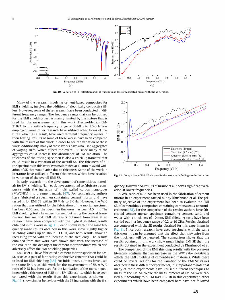
Many of the research involving cement-based composites forEMI shielding, involves the addition of electrically conductive fil-lers. However, some of these research have been conducted in dif-ferent frequency ranges. The frequency range that can be utilisedfor the EMI shielding test is mainly limited by the fixture that isused for the measurements. In this work, Electro-Metrics EM-2107A fixture with a frequency range of 30 MHz to 1.5 GHz wasemployed. Some other research have utilised other forms of fix-tures, which as a result, have used different frequency ranges intheir testing. Results of some of these works have been comparedwith the results of this work in order to see the variation of thesework. Additionally, many of these works have also used aggregatesof varying sizes, which affects the overall SE since many of theaggregates could increase the absorbance of EM radiation. Thethickness of the testing specimen is also a crucial parameter thatcould result in a variation of the overall SE. The thickness of allthe specimens in this work was maintained at 10 mm to avoid vari-ation of SE that would arise due to thickness. Some of the work inliterature have utilised different thicknesses which have resultedin variation of the overall EMI SE.
In early research into the development of cementitious materi-als for EMI shielding, Nam et al. have attempted to fabricate a com-posite with the inclusion of multi-walled carbon nanotubes(MWCNTs) into a cement matrix [67]. For comparison, authorshave fabricated a specimen containing cement mortar and havetested it for EMI SE within 30 MHz to 3 GHz. However, the W/Cration that was utilised for the fabrication of the mortar specimenhas been 0.65, and the specimen thickness has been 4.5 mm. TheEMI shielding tests have been carried out using the coaxial trans-mission line method. EMI SE results obtained from Nam et al.research have been compared with the highest shielding resultsobtained in this work in Fig. 11. Graph shows within the same fre-quency range results obtained in this work show slightly highershielding values up to about 1.1 GHz, and both results show anincreasing trend with the increase of the frequency. The resultsobtained from this work have shown that with the increase ofthe W/C ratio, the density of the cement mortar reduces which alsoadversely affect the EMI shielding properties.
Krause et al. have fabricated a cement mortar specimen for EMISE tests as a part of fabricating conductive concrete that could beutilised for EMI shielding [33]. For initial tests, authors have usedthe same fixture as this work for the measurement of SE. A W/Cratio of 0.48 has been used for the fabrication of the mortar spec-imen with a thickness of 6.35 mm. EMI SE results, which have beencompared with the results from this experiment, as shown inFig. 11, show similar behaviour with the SE increasing with the fre-
quency. However, SE results of Krause et al. show a significant vari-ation at lower frequencies.
A W/C ratio of 0.35 has been used in the fabrication of cementmortar in an experiment carried out by Khushnood et al. The pri-mary objective of the experiment has been to evaluate the EMISE of cementitious composites containing carbonaceous nano/mi-cro inerts [68]. For the comparison of the results, authors have fab-ricated cement mortar specimen containing cement, sand, andwater with a thickness of 10 mm. EMI shielding tests have beencarried out in a frequency range of 0.2 to 10 GHz. Results obtainedare compared with the SE results obtained for this experiment inFig. 11. Since both research have used specimens with the samethickness, it can be assumed that the effect that may arise fromthe thickness will be negated. The comparison shows that theresults obtained in this work show much higher EMI SE than theresults obtained in the experiment conducted by Khushnood et al.
The comparison of the EMI shielding results with the previousliterature confirms that an increase in the W/C ratio negativelyaffects the EMI shielding of cement-based materials. While therecould be several reasons for the variation of the EMI SE valuesobtained in these different experiments, it is important to note thatmany of these experiments have utilised different techniques tomeasure the EMI SE. While the measurements of EMI SE were car-ried out according to ASTM D4935 – 18 in this experiment, otherexperiments which have been compared here have not followed
Fig. 10. Variation of (a) reflection and (b) transmission loss of fabricated mixes with the W/C ratios.
Fig. 11. Comparison of EMI SE obtained in this work with findings in the literature.
8 D. Wanasinghe et al. / Construction and Building Materials 256 (2020) 119409
48

the same standard. However, with all the variations in each exper-iment, it can be seen from Fig. 11 that all these experiments yieldalmost the same amount of SE. While this SE is an extremely smallvalue, results from this experiment have shown that W/C ratio canact as an important parameter for the EMI SE.
The variation of the EMI shielding of mixes containing FA isshown in Figs. 12, 13, and 14, with W/C ratios of 0.3, 0.4, and 0.5respectively. Fig. 15 compares the highest SE obtained in mixes
with FA and different W/C ratios. The EMI SE results show thatthe increase of the FA content leads to higher SE. The primary rea-son for the increased SE is due to the incorporation of Fe2O3 intothe specimens from FA. The chemical composition of FA given inTable 2 shows FA contains approximately 10% Fe2O3. Increasingthe W/C ratio also increases the EMI SE of mixes containing FA asshown in Fig. 15. While FA adds EM wave absorbing Fe2O3 intospecimens, the increased water content would lead to higher
Fig. 12. Variation of (a) reflection and (b) transmission loss of fabricated mixes with varying amount of FA with the W/C ratio of 0.3.
Fig. 13. Variation of (a) reflection and (b) transmission loss of fabricated mixes with varying amount of FA with the W/C ratio of 0.4.
Fig. 14. Variation of (a) reflection and (b) transmission loss of fabricated mixes with varying amount of FA with the W/C ratio of 0.5.
D. Wanasinghe et al. / Construction and Building Materials 256 (2020) 119409 9
49

porosity, which would lead to a lower density of the specimen. Theoverall EMI SE of the specimens takes place from the synergeticeffects of all these factors; hence, there are variations of SE in spec-imens containing the same W/C ratio. The comparison shown inFig. 15 shows that the overall SE increases with the FA content.Hence, the primary form of shielding mechanism is the absorptionof EM waves from the Fe2O3 in the specimen. Increased FA contentshows a similar pattern in literature as findings of this work[48,69]. However, many of these research have been conductedin different frequency ranges. The optimum amount of EMI shield-ing was obtained in the mix containing 1.8 FA with 0.4 W/C ratio.
EMI SE of materials containing GGBFS is graphically shown fromFigs. 16 to 18. Fig. 19 compares the highest EMI SE obtained foreach W/C ratio. The variation of EMI SE of the mixes with slagtends to increase with the slag content, reach a saturation valueand then decrease. For the mixes with a W/C ratio of 0.3 the max-imum SE is obtained for the mix containing 1.5 slag. However, thesame mix shows lower SE at lower frequencies. When the slag con-tent is increased to 1.8, the EMI SE reduces to the lowest value outof the three mixes. Other two mixes with W/C ratios of 0.4 and 0.5both show that the EMI SE is lowest when the slag content isincreased to 1.8. The SE of mix with a W/C ratio of 0.4 and slag con-tent of 1.2 and 1.5 show near-identical behaviour. When the W/Ccontent is increased to 0.5, the highest SE is obtained by the mixcontaining the lowest slag content.
The increase of the porosity with the increase of the slag con-tent, as reported in the literature, is one of the reasons why theEMI SE is higher at lower frequencies with the increase of the slag
content. When the slag content is increased the overall SE ofalmost all the mixes tend to reach a saturation level and thendecrease indicating that the density of the material would increasethen decrease drastically with the reduction of the calcium sili-cates. Since slag does not contain specific material that wouldabsorb EM waves, the mechanism of shielding would take placefrom the perovskite minerals present in slag [70]. The presenceof perovskite is known to significantly increase the EMI SE of cera-mic materials [71,72]. The increased conductivity of the specimensas a result of the addition of slag in combination with the per-ovskite structure would be the primary reasons why mixes con-taining slag shows the highest amount of SE in this study. Theoptimum level of slag and the W/C ratio for the best shieldingresults were found to be 1.2 GGBFS and 0.4 W/C.
To observe the effect of each additive with respect to the mixwith no additives, the optimum SE of each mix plotted, which isshown in Fig. 20. The comparison shows the best EMI SE isachieved when the mix contains 1.2 slag with 0.4 W/C ratio. Com-pared to the mix containing no additives, both FA and GGBFS mixesshow lower SE at lower frequencies that may arise as a result ofhigher porosity in these materials. However, with the increase ofthe frequency, the mix with GGBFS shows much better SE thanthe other two. As previously stated, the primary reason for thishigher SE can be attributed to the presence of perovskite mineralsin GGBFS [73]. Even though FA contains Fe2O3, which can absorbEM waves, lower percentage of it is insufficient to produce high SE.
Though these results provide promising results for futureresearch into cementitious materials that could be developed for
Fig. 15. Comparison of (a) reflection and (b) transmission SE of mixes containing FA.
Fig. 16. Variation of (a) reflection and (b) transmission loss of fabricated mixes with varying amount of slag with the W/C ratio of 0.3.
10 D. Wanasinghe et al. / Construction and Building Materials 256 (2020) 119409
50

EMI shielding, comparison with the standard of EMI shieldingrequirement shows that these mixes need a significant amountof improvements to meet industrial requirements. MIL-STD-188–125-1 standard [26], which contains details of required EMI SE,shows that at a frequency of 1 GHz an EMI SE of 80 dB should bepresent in a structure. With the increase of the frequency, thisreduces linearly up to 1.5 GHz, where no SE can be there. In order
to meet this amount of SE, these mixes need to have additionaladditives that would boost their SE.
3.4. SEM characterisation
SEM analysis was carried out for the observation of themicrostructural characterisation of the specimens with the varia-
Fig. 17. Variation of (a) reflection and (b) transmission loss of fabricated mixes with varying amount of slag with the W/C ratio of 0.4.
Fig. 18. Variation of (a) reflection and (b) transmission loss of fabricated mixes with varying amount of slag with the W/C ratio of 0.5.
Fig. 19. Comparison of (a) reflection and (b) transmission SE of mixes containing slag with different W/C ratios.
D. Wanasinghe et al. / Construction and Building Materials 256 (2020) 119409 11
51

tion of the W/C ratio, which is shown in Fig. 21. Results from themechanical and EMI SE indicates that the porosity of the specimensincreases with the increase of the water content. The SEM analysisconfirms these findings where the structure shows a highly porousstructure in W5 specimen where the W/C ratio is 0.5, while thestructure of W3 specimen with a W/C ratio of 0.3 is much denser.
These observations conform to numerous research on the cementi-tious materials and the W/C ratio.
SEM analysis conducted on specimens containing FA shows thatthe spherical shaped FA particles have been distributed evenlythroughout the matrix. Additionally, images also show the distri-bution of hydration products and pores within the matrix. Fig. 22
Fig. 20. Comparison of highest (a) reflection and (b) transmission SE of specimens with no additives (W3), FA (W4F1.8), and GGBFS (W4S1.2).
Fig. 21. SEM Micrographs of (a) W3, (b) W4, and (c) W5 mixes.
Fig. 22. SEM image of the mix containing 1.2 FA with 0.3 W/C ratio. Fig. 23. SEM image of the mix containing 1.2 GGBFS with 0.3 W/C ratio.
12 D. Wanasinghe et al. / Construction and Building Materials 256 (2020) 119409
52

shows the SEM image of the mix consisting of 1.2 FA with 0.3 W/Cratio.
SEM characterisation of specimens containing GGBFS shows thedistribution of slag particles within the matrix consisting of hydra-tion products with a considerable amount of porosity. Fig. 23shows the SEM image for the mix containing 1.2 GGBFS with aW/C ratio of 0.3. Observations of the SEM analysis leads to the con-clusion that the porosity of the specimen could be increased withthe addition of GGBFS, which are confirmed from the results ofthe mechanical tests. EMI shielding of the mixes containing GGBFSwould result from the porous structure and the GGBFS particleswhich are evenly distributed within the matrix.
4. Conclusions
For the investigation of W/C ratio, FA, and GGBFS on EMI SE,cement mixes with different water content and additives were fab-ricated and tested for various properties in this research. A wholerange of properties, including mechanical, electrical conductivity,SEM, and EMI shielding, was measured by employing suitable testsfor the characterisation of the specimens. EMI shielding tests werecarried out within 30 MHz to 1.5 GHz frequency range with accor-dance to ASTM D4935 – 18.
1. Electrical conductivity, which was carried out by using the four-probe technique shows that the increase of theW/C ratio resultsin an increase of the dry conductivity of the specimens. Compar-ison of these findings with the previous findings in the literatureshows that the increased pore structure results in higher ionicconductivity in cement-based composites. The electrical con-ductivity of FA mixes shows a drastic reduction with the highamount of FA addition. The reduction of the pore size, whichresults due to the addition of FA is known to be the primary rea-son for this behaviour. Conductivity gradually decreases withthe inclusion of GGBFS for a givenW/C ratio. The primary reasonfor this reduction can be identified as the reduction of ions thatis essential in electrical conductivity of dry mortar. Increasingthe water content leads to an increase in electrical conductivityas it would increase the pore structure within the material.
2. EMI SE analysis shows a decrease with the increasing W/C ratiowithin the tested frequency range. The increase of the voidswithin specimens due to increased W/C ratio would lead to adecrease of the density of the specimens, whichwould adverselyaffect the EMI absorption by the specimen. Even though theincreased pore structure would lead to higher multiple reflec-tions, it is has a smaller effect compared with the reflectionand the absorption of EMI. As a result, it was concluded thatthe specimens containing a W/C ratio of 0.3 yields the best EMIshielding and mechanical properties required by the industry.
3. Inclusion of FA increases the EMI SE of mortar with the FA con-tent. However, the porosity created by the FA leads to poorshielding properties at lower frequencies. Increasing the W/Cratio also leads to poor overall SE in mixes containing FA. Theprimary form of shielding in mixes with FA can be attributedto the presence of Fe2O3, which can effectively absorb EM radi-ation. The optimum shielding for the mixes containing FA wasfound to be the mix with 1.8 FA with 0.4 W/C ratio.
4. Addition of GGBFS increased the overall SE in cementitiousmixes and reach a saturation level and gradually decreases withfurther addition. The presence of perovskite minerals withinGGBFS leads to higher SE in comparison to other mixes testedin this work. The increase of W/C ratio leads to poor shieldingproperties due to the formation of pores within the matrix.The mix with highest EMI SE, which contains GGBFS was foundto be 1.2 GGBFS with 0.4 W/C ratio.
CRediT authorship contribution statement
Dimuthu Wanasinghe: Conceptualization, Data curation, For-mal analysis, Investigation, Methodology, Software, Validation,Visualization, Writing - original draft. Farhad Aslani: Fundingacquisition, Supervision, Project administration, Resources, Con-ceptualization, Methodology, Data curation, Writing - review &editing. Guowei Ma: Funding acquisition, Supervision.
Declaration of Competing Interest
The authors declare that they have no known competing finan-cial interests or personal relationships that could have appearedto influence the work reported in this paper.
References
[1] P. Stavroulakis, Biological Effects of Electromagnetic Fields: Mechanisms,Modeling, Biological Effects, Therapeutic Effects, International Standards,Exposure Criteria, Springer, Berlin Heidelberg, 2013.
[2] A. B. Lavanya, ‘‘Effects of electromagnetic radiation on biological systems: ashort review of case studies,” in 8th International Conference onElectromagnetic Interference and Compatibility, 2003, vol. 2003-Janua, pp.87–90.
[3] A. Zamanian and C. Hardiman, ‘‘Electromagnetic Radiation and Human Health:A Review of Sources and Effects,” no. July, 2005.
[4] D. P. Sager, ‘‘Current facts on pacemaker electromagnetic interference andtheir application to clinical care,” Hear. Lung; (United States).
[5] C. Binggeli et al., Induction Ovens and Electromagnetic Interference: What Isthe Risk for Patients with Implantable Cardioverter Defibrillators?, JCardiovasc. Electrophysiol. 16 (4) (2005) 399–401.
[6] P. Crerar, J. Henley, and P. Wintour, ‘‘Russia accused of cyber-attack onchemical weapons watchdog,” The Guardian, 2019. [Online]. Available: https://www.theguardian.com/world/2018/oct/04/netherlands-halted-russian-cyber-attack-on-chemical-weapons-body. [Accessed: 29-Sep-2019].
[7] D. Wanasinghe, F. Aslani, A review on recent advancement of electromagneticinterference shielding novel metallic materials and processes, Compos. Part BEng. 176 (2019) 107207.
[8] A. Shishkin, T. Koppel, V. Mironov, I. Hussainova, J. Locs, H. Haldre, MicrowaveReflectance and Transmittance Properties of Conductive Composite Materials,Energy Procedia 113 (2017) 354–361.
[9] T. Koppel, A. Shishkin, H. Haldre, N. Toropov, P. Tint, Reflection andTransmission Properties of Common Construction Materials at 2.4 GHzFrequency, Energy Procedia 113 (2017) 158–165.
[10] B. Zukowski, Y.G. dos Santos Mendonça, J.V.B. de Souza, R.D.T. Filho, ‘‘Cement-based EMI shielding materials”, in Materials for Potential EMI Shielding,Applications, Elsevier (2020) 333–340.
[11] D. Zhao, J. Chen, Q. Gao, H.Y. Ge, Graphene Oxide/Cement Composites forElectromagnetic Interference Shielding, Mater. Sci. Forum 809–810 (2015)(2014) 485–489.
[12] W. L. Yao, G. X. Xiong, and Y. Yang, ‘‘Electromagnetic Shielding Effectiveness ofNickel Fiber-Reinforced Cement Composites,” Mater. Sci. Forum, vol. 898, no.Mc, pp. 2065–2070, 2017.
[13] S. Muthusamy and D. D. L. Chung, ‘‘Carbon-Fiber Cement-Based Materials forElectromagnetic Shielding.,” ACI Mater. J., vol. 107, no. 6, 2010.
[14] S. Kovar, J. Valouch, H. Urbancokova, Calculation of Shielding Effectiveness ofMaterials for Security Devices, MATEC Web Conf. 125 (Oct. 2017) 02036.
[15] S. Sankaran, K. Deshmukh, M. B. Ahamed, and S. K. Khadheer Pasha, ‘‘Recentadvances in electromagnetic interference shielding properties of metal andcarbon filler reinforced flexible polymer composites: A review,” Compos. PartA Appl. Sci. Manuf., vol. 114, no. April, pp. 49–71, 2018.
[16] A. Joshi, S. Datar, Carbon nanostructure composite for electromagneticinterference shielding, Pramana - J. Phys. 84 (6) (2015) 1099–1116.
[17] X.C. Tong, Advanced Materials and Design for Electromagnetic InterferenceShielding, 1st ed., CRC Press, Florida, 2009.
[18] A.K. Singh, A. Shishkin, T. Koppel, N. Gupta, A review of porous lightweightcomposite materials for electromagnetic interference shielding, Compos. PartB Eng. 149 (May) (2018) 188–197.
[19] A.K. Singh, A. Shishkin, T. Koppel, N. Gupta, ‘‘Porous materials for EMIshielding”, in Materials for Potential EMI Shielding, Applications, Elsevier (2020)287–314.
[20] H. Sato, H. Domae, M. Takahashi, M. Abe, Reflection and Transmission Controlof Electromagnetic Wave for Concrete Walls, Electron. Commun. Japan (Part IIElectron. 83 (11) (2000) 12–21.
[21] R. Panigrahi, S.K. Srivastava, Trapping of microwave radiation in hollowpolypyrrole microsphere through enhanced internal reflection: A novelapproach, Sci. Rep. 5 (2015) 1–10.
[22] ASTM Committee on Standards, ASTM E1851–15, Standard Test Method forElectromagnetic Shielding Effectiveness of Durable Rigid Wall RelocatableStructures, ASTM International, Pennsylvania, 2015, pp. 1–15.
D. Wanasinghe et al. / Construction and Building Materials 256 (2020) 119409 13
53

[23] ASTM Committee on Standards, ‘‘ASTM D4935-18, Standard Test Method forMeasuring the Electromagnetic Shielding Effectiveness of Planar Materials.”ASTM International, Pennsylvania, p. 11, 2018.
[24] IEEE Standards Association, ‘‘IEEE Standard Method for Measuring theEffectiveness of Electromagnetic Shielding Enclosures.” The Institute ofElectrical and Electronics Engineers, Inc., New York, p. 52, 2007.
[25] IEEE Standards Association, ‘‘IEEE Standard Method for Measuring theShielding Effectiveness of Enclosures and Boxes Having all Dimensionsbetween 0.1 m and 2 m.” The Institute of Electrical and ElectronicsEngineers, Inc., New York, p. 96, 2014..
[26] Department of Defense, ‘‘MIL-STD-188-125-1 High-Altitude Electromagnetic(HEMP) Protection for Ground Based C41 Facilities.” US Military Specs/Standards/Handbooks, Virginia, p. 106, 2005.
[27] H. Vasquez, L. Espinoza, and K. Lozano, ‘‘Simple Device for ElectromagneticInterference Shielding Effectiveness Measurement,” IEEE, pp. 62–68, 2009.
[28] P. G. de Francisco, D. Poyatos Martinez, B. P. Gallardo, D. Escot Bocanegra, andS. F. Romero, ‘‘Limitations in the Measurement of the Shielding Effectiveness ofAeronautical Multi-ply CFC Laminates,” in 2019 International Symposium onElectromagnetic Compatibility - EMC EUROPE, 2019, pp. 662–667.
[29] T. Viheriäkoski, R. Wong, R. Fung, P. Tamminen, Characterization of ESDshielding materials with novel test methods, J. Phys. Conf. Ser. 1322 (1) (Oct.2019) 012023.
[30] S. Yehia, N. Qaddoumi, M. Hassan, B. Swaked, Conductive Concrete forElectromagnetic Shielding Applications, Adv. Civ. Eng. Mater. 3 (1) (2014)20130107.
[31] A. Krause et al., Conductive concrete as an electromagnetic shield, IEEE Int.Symp. Electromagn. Compat (2012) 85–87.
[32] A. Ogunsola, U. Reggiani, and L. Sandrolini, ‘‘Shielding properties of conductiveconcrete against transient electromagnetic disturbances,” in 2009 IEEEInternational Conference on Microwaves, Communications, Antennas andElectronics Systems, 2009, no. 1, pp. 1–5.
[33] A.P. Krause, L. Nguyen, C.Y. Tuan, J.D. Blasey, Conductive Concrete: a ShieldingConstruction Material, J. Radiat. Eff. 31 (1) (2013) 151–158.
[34] A. Shishkin, I. Hussainova, V. Kozlov, M. Lisnanskis, P. Leroy, D. Lehmhus,Metal-Coated Cenospheres Obtained via Magnetron Sputter Coating: A NewPrecursor for Syntactic Foams, JOM 70 (7) (Jul. 2018) 1319–1325.
[35] D. Wanasinghe, F. Aslani, G. Ma, D. Habibi, Advancements in electromagneticinterference shielding cementitious composites, Constr. Build. Mater. 231 (Jan.2020) 117116.
[36] S. Goto, D.M. Roy, The effect of w/c ratio and curing temperature on thepermeability of hardened cement paste, Cem. Concr. Res. 11 (4) (Jul. 1981)575–579.
[37] A. Shamsai, S. Peroti, K. Rahmani, L. Rahemi, Effect of water-cement ratio onabrasive strength, porosity and permeability of nano-silica concrete, WorldAppl. Sci. J. 17 (8) (2012) 929–933.
[38] H. Guan, S. Liu, Y. Duan, Y. Zhao, Investigation of the electromagneticcharacteristics of cement based composites filled with EPS, Cem. Concr.Compos. 29 (1) (2007) 49–54.
[39] X. Lv, Y. Duan, G. Chen, Electromagnetic wave absorption properties ofcement-based composites filled with graphene nano-platelets and hollowglass microspheres, Constr. Build. Mater. 162 (2018) 280–285.
[40] L.K.A. Sear, Properties and Use of Coal Fly Ash, A Valuable Industrial By-product.Thomas Telford (2001).
[41] K. Wesche, Fly Ash in Concrete: Properties and performance, Taylor & Francis,2004.
[42] P. Hou, S. Kawashima, K. Wang, D.J. Corr, J. Qian, S.P. Shah, Effects of colloidalnanosilica on rheological and mechanical properties of fly ash–cement mortar,Cem. Concr. Compos. 35 (1) (Jan. 2013) 12–22.
[43] C.S. Poon, L. Lam, Y.L. Wong, Effects of Fly Ash and Silica Fume on InterfacialPorosity of Concrete, J. Mater. Civ. Eng. 11 (3) (Aug. 1999) 197–205.
[44] J. Baronins, J. Setina, G. Sahmenko, S. Lagzdina, A. Shishkin, Pore Distributionand Water Uptake in a Cenosphere-Cement Paste Composite Material, IOPConf. Ser. Mater. Sci. Eng. 96 (1) (Nov. 2015) 012011.
[45] H. Yazıcı, M.Y. Yardımcı, H. Yigiter, S. Aydın, S. Türkel, Mechanical properties ofreactive powder concrete containing high volumes of ground granulated blastfurnace slag, Cem. Concr. Compos. 32 (8) (Sep. 2010) 639–648.
[46] S. Teng, T.Y.D. Lim, B. Sabet Divsholi, Durability and mechanical properties ofhigh strength concrete incorporating ultra fine Ground Granulated Blast-furnace Slag, Constr. Build. Mater., Mar. 40 (2013) 875–881.
[47] H. Zhao, W. Sun, X. Wu, B. Gao, The properties of the self-compacting concretewith fly ash and ground granulated blast furnace slag mineral admixtures, J.Clean. Prod. 95 (May 2015) 66–74.
[48] M. Ozturk, O. Akgol, U.K. Sevim, M. Karaaslan, M. Demirci, E. Unal,Experimental work on mechanical, electromagnetic and microwaveshielding effectiveness properties of mortar containing electric arc furnaceslag, Constr. Build. Mater. 165 (2018) 58–63.
[49] Australian Standard, ‘‘General purpose and blended cements (AS 3972-2010).”Standards Australia, Sydney, p. 29, 2010.
[50] Australian Standard, ‘‘Supplementary cementitious materials Part 3 :Amorphous silica (AS/NZS 3582.3:2016).” Standards Australia, Sydney, p. 21,2016.
[51] Australian Standard, ‘‘Supplementary cementitious materials Part 3 :Amorphous silica (AS/NZS 3582.3:2016).” Standards Australia, Sydney, p. 21,2016.
[52] Australian Standard, ‘‘Supplementary cementitious materials Part 3 :Amorphous silica (AS/NZS 3582.3:2016).” Standards Australia, Sydney, p. 21,2016.
[53] Australian Standard, ‘‘Methods of testing concrete Method 8.1: Method formaking and curing concrete—Compression and indirect tensile test specimens(AS 1012.8.1:2014).” Standards Australia, Sydney, p. 13, 2014.
[54] T. Koppel, I. Vilcane, V. Mironov, A. Shiskin, S. Rubene, P. Tint, Aerated ConcreteMicrowave Reflection and Transmission Properties in a Wet Environment,Environ. Technol. Resour. Proc. Int. Sci. Pract. Conf. 3 (2017) 145.
[55] S.B. Singh, P. Munjal, N. Thammishetti, Role of water/cement ratio on strengthdevelopment of cement mortar, J. Build. Eng. 4 (2015) 94–100.
[56] M. Zabihi-Samani, S.P. Mokhtari, F. Raji, Effects of Fly Ash on MechanicalProperties of Concrete, J. Appl. Eng. Sci. 8 (2) (2018) 35–40.
[57] Ö. Çakır, F. Aköz, Effect of curing conditions on the mortars with and withoutGGBFS, Constr. Build. Mater. 22 (3) (2008) 308–314.
[58] I.B. Topu, T. Uygunolu, I. Hocaolu, Electrical conductivity of setting cementpaste with different mineral admixtures, Constr. Build. Mater. 28 (1) (2012)414–420.
[59] A.A. Ramezanianpour, V.M. Malhotra, Effect of curing on the compressivestrength, resistance to chloride-ion penetration and porosity of concretesincorporating slag, fly ash or silica fume, Cem. Concr. Compos. 17 (2) (1995)125–133.
[60] A. Berg, G.A. Niklasson, K. Brantervik, B. Hedberg, L.O. Nilsson, Dielectricproperties of cement mortar as a function of water content, J. Appl. Phys. 71(12) (1992) 5897–5903.
[61] S.A.A. El-Enein, M.F. Kotkata, G.B. Hanna, M. Saad, M.M.A. El Razek, Electricalconductivity of concrete containing silica fume, Cem. Concr. Res. 25 (8) (1995)1615–1620.
[62] R. Kurda, J. de Brito, and J. D. Silvestre, ‘‘Water absorption and electricalresistivity of concrete with recycled concrete aggregates and fly ash,” Cem.Concr. Compos., vol. 95, no. August 2018, pp. 169–182, Jan. 2019.
[63] A. Lübeck, A.L.G. Gastaldini, D.S. Barin, H.C. Siqueira, Compressive strength andelectrical properties of concrete with white Portland cement and blast-furnaceslag, Cem. Concr. Compos. 34 (3) (2012) 392–399.
[64] S.C. Ryu, J.Y. Kim, C. Cho, W.N. Kim, Improvements of the ElectricalConductivity and EMI Shielding Efficiency for the Polycarbonate/ABS/CarbonFiber Composites Prepared by Pultrusion Process, Macromol. Res. 28 (2) (2020)118–125.
[65] M. Mahmoodi, M. Arjmand, U. Sundararaj, S. Park, The electrical conductivityand electromagnetic interference shielding of injection molded multi-walledcarbon nanotube/polystyrene composites, Carbon N. Y. 50 (4) (2012) 1455–1464.
[66] A.A. Al-Ghamdi et al., Correlation between Electrical Conductivity andMicrowave Shielding Effectiveness of Natural Rubber Based Composites,Containing Different Hybrid Fillers Obtained by Impregnation Technology,Mater. Sci. Appl. 07 (09) (2016) 496–509.
[67] I.W. Nam, H.K. Lee, J.B. Sim, S.M. Choi, Electromagnetic Characteristics ofCement Matrix Materials with Carbon Nanotubes, ACI Mater. J. 109 (3) (2012)363–370.
[68] R.A. Khushnood, S. Ahmad, P. Savi, J.M. Tulliani, M. Giorcelli, G.A. Ferro,Improvement in electromagnetic interference shielding effectiveness ofcement composites using carbonaceous nano/micro inerts, Constr. Build.Mater. 85 (2015) 208–216.
[69] I.W. Nam, H.K. Lee, Synergistic effect of MWNT/fly ash incorporation on theEMI shielding/absorbing characteristics of cementitious materials, Constr.Build. Mater. 115 (2016) 651–661.
[70] M. Hu, L. Liu, X. Lv, C. Bai, S. Zhang, Crystallization Behavior of Perovskite in theSynthesized High-Titanium-Bearing Blast Furnace Slag Using ConfocalScanning Laser Microscope, Metall. Mater. Trans. B 45 (1) (2014) 76–85.
[71] S. Ghahari, E. Ghafari, N. Lu, Effect of ZnO nanoparticles on thermoelectricproperties of cement composite for waste heat harvesting, Constr. Build.Mater. 146 (2017) 755–763.
[72] W. Ari Adi et al., ‘‘Metamaterial: Smart Magnetic Material for MicrowaveAbsorbing Material”, in Electromagnetic Fields and Waves, vol. i, no. tourism,IntechOpen (2019) 13.
[73] L. Liu, M. Hu, C. Bai, X. Lv, L. Wen, S. Zhang, In situ observation of thecrystallisation process of perovskite in titanium-bearing blast furnace slag,Miner. Process. Extr. Metall. 123 (4) (2014) 241–245.
14 D. Wanasinghe et al. / Construction and Building Materials 256 (2020) 119409
54

Chapter 4: Electromagnetic shielding properties of carbon fibre reinforced cementitious
composites
The initial literature review revealed that fibre additives would impart high electrical
conductivity in composites with poor conductive matrices. Out of the fibres used in previous
research, carbon fibre (CF) has been able to produce better results than metal fibres. To study
the effect of CFs in electromagnetic shielding, two different fibres known as unsized and
desized were selected. The difference between these two types is that unsized CFs have their
surface coating removed, whereas desized fibres have their coating intact. Three different
lengths of 3, 6, and 12 mm unsized CFs and two different lengths of 6 and 12 mm desized CFs
were used in composite fabrication. From each fibre size, four weight percentages of 0.1, 0.3,
0.5, and 0.7 were added to the established control mix to analyse their properties. All the
specimens were tested for their mechanical, electrical, and electromagnetic shielding
properties. Results showed that unsized fibres had better shielding than desized due to having
better conductivity. Additionally, the amount of shielding increased with the fibre size and
amount. The maximum amount of shielding was generated by the specimen with 0.7 wt% 12
mm unsized CFs, which was 50.65 dB. This chapter consists of the following publication and
included in the thesis in the published format.
Wanasinghe, D., Aslani, F., & Ma, G. (2020b). Electromagnetic shielding properties of carbon
fibre reinforced cementitious composites. Construction and Building Materials, 260, 120439.
https://doi.org/10.1016/j.conbuildmat.2020.120439
55

Electromagnetic shielding properties of carbon fibre reinforcedcementitious composites
Dimuthu Wanasinghe a, Farhad Aslani a,b,⇑, Guowei Ma a
aMaterials and Structures Innovation Group, School of Engineering, The University of Western Australia, WA, Australiab School of Engineering, Edith Cowan University, WA 6027, Australia
h i g h l i g h t s
� CFs enhance flexural strength in cementitious composites.� Electrical conductivity increases and reaches a saturation level with CF loading.� EMI shielding is better in composites with unsized CF compared to desized CFs.� EMI shielding increases with the unsized CF loading and length.
a r t i c l e i n f o
Article history:Received 1 March 2020Received in revised form 17 May 2020Accepted 30 July 2020
Keywords:Electromagnetic shieldingCementitious compositesCarbon fibre
a b s t r a c t
The need for construction materials with high electromagnetic (EM) shielding properties is growing glob-ally due to the rapid development of electronic devices. This study has aimed at fabricating a cement-based composite that could be developed for electromagnetic shielding applications within the industry.To impart EM shielding properties, unsized carbon fibres with lengths of 3 mm, 6 mm, and 12 mm anddesized carbon fibres with lengths of 6 mm and 12 mm were mixed to a control mix. Different weightfractions of 0.1%, 0.3%, 0.5%, and 0.7% of carbon fibres of each type were used in the fabrication of spec-imens. Each mix was subjected to mechanical, electrical conductivity, electromagnetic interferenceshielding, and scanning electron microscope analyses for characterisation. Results show that the additionof carbon fibres has a significant improvement in flexural, electrical conductivity, and electromagneticinterference shielding properties. The mix with the highest electrical conductivity was the one withunsized 12 mm carbon fibres with a weight fraction of 0.7%. The same mix showed the best electromag-netic interference shielding properties, which was about 40–60 dB within 300 MHz to 1.5 GHz frequencyrange. Comparison of obtained results with mixes reported in the literature containing carbon within acement matrix showed that electromagnetic interference shielding performance of the best mix in thisstudy exceeded performance reported in the literature for the same frequency range.
� 2020 Elsevier Ltd. All rights reserved.
1. Introduction
Electromagnetic radiation is a common form of radiation that isfound in nature, such as natural light [1]. However, the advance-ment of the electronics industry has led to a flood of electromag-netic radiations of different wavelengths. Such an influx ofradiation to the atmosphere would eventually lead to what isknown as electromagnetic pollution [2–5]. Such a phenomenoncould lead to electromagnetic interference (EMI), which results inthe malfunction of electronic devices [6]. Most of the EMI would
result in harmless outcomes in electronic devices. However, insome instances, prolonged exposure to high-frequency electro-magnetic radiation could lead to adverse outcomes within humansand the malfunction of other electronic devices [7–10].
Additionally, EMI is known to cause malfunction of critical elec-tronic devices such as pacemakers, endangering human lives [11–14]. Electromagnetic radiation could also be used for hacking intocomputer networks in order to steal classified data [15]. Inten-tional EMI could also be used as a weapon during warfare to crip-ple computer networks [16–21]. As a result of these, there havebeen numerous attempts to fabricate constructional materials toprovide shielding properties against electromagnetic radiation.
Metals have been the conventionally used materials used forshielding against electromagnetic radiation. Metals can create a
https://doi.org/10.1016/j.conbuildmat.2020.1204390950-0618/� 2020 Elsevier Ltd. All rights reserved.
⇑ Corresponding author at: Materials and Structures Innovation Group, School ofEngineering, The University of Western Australia, WA, Australia.
E-mail address: [email protected] (F. Aslani).
Construction and Building Materials 260 (2020) 120439
Contents lists available at ScienceDirect
Construction and Building Materials
journal homepage: www.elsevier .com/locate /conbui ldmat
56

Faraday’s cage, when subjected to electromagnetic radiation, dueto their high electrical conductivity, protecting instruments within[22,23]. High conductive metal sheets are used for instances wherehigh protection from electromagnetic radiation, such as in roomswith magnetic resonance scanners, is necessary. However, themetal cladding that needs to be installed for this kind of protectionwould require constant maintenance since metals are prone to cor-rosion [24–26]. The installation of such cladding also incurs addi-tional constructional costs [27–29]. Hence, there has been anincreased number of research focusing on fabricating EMI shieldingconstructional materials that would not require additional clad-dings. Many of these research have focused on cementitious com-posites since cement is the primary constructional material used todate [30–39].
The natal EMI shielding properties of cement mortar is extre-mely poor. Hence, many of the research focused on making cementwith EMI shielding properties include additives that would absorbelectromagnetic radiations and increase the electrical conductivityof the cement mix [40,41]. Increasing the electrical conductivityhelps cementitious composite to increase their EMI shielding prop-erties since the interaction of electromagnetic radiation with highconductive additives would result in the electrical current beinginduced within them, which diminishes the intensity of the inci-dent EM radiation [42].
Theoretically, total EMI shielding (SET) occurs by three mecha-nisms known as reflection (SER), absorption (SEA), and multiplereflection (SEM), as represented in equation (1).
SET ¼ SEA þ SER þ SEM ð1ÞElectromagnetic waves get reflected from a material surface
due to impedance mismatch between the incident electromagneticwaves and the material surface [43]. For the calculation of thereflection component, equation (2) can be used, where r is the con-ductivity, f is the frequency of the EM waves, e is the electric per-mittivity, and lr is the relative permeability [44].
SER ¼ �10log10r
16f elr
� �ð2Þ
Waves that penetrate the surface could undergo absorption ormultiple reflection losses. The absorption of the electromagneticwaves is the result of dielectric properties of the material thatwould result in the generation of heat, which results in an attenu-ation the waves [44,45]. Theoretically, the absorbing componentcan be calculated using Eq. (3), where a is the rate of attenuationand z is the thickness of the material [46].
SEA ¼ 20log101
e�az
� �ð3Þ
Presence of multiple surfaces within the material is known tobe the primary reason for multiple reflection of electromagneticwaves (EMWs) [44]. The presence of different material with impe-dance mismatches makes the EMWs undergo reflections, whichthen would reflect within the material further for the same reason.However, compared to the reflection and absorption losses, theamount of EMI shielding produced by multiple reflection is verysmall [27]. Calculation of the multiple reflection of EM waves canbe carried out using Eq. (4), where d is the skin depth [27].
SEM ¼ 20log10 1� e�2zd
� �ð4Þ
There are different methods developed to measure the amountof shielding provided by a material. One of the most commonlyused standards used for the EMI shielding measurement of planermaterials is ASTM D4935 – 18 [47], which is based on the coaxialtransmission line technique. While this standard describes thedimensions of the specimen and the frequency range to be used
for the measurement, it also describes the fixture that is neededto be used for measurement. A technique based on the shieldedroom technique is described in MIL-STD-188-125-1 standard,which details the requirement for EMI shielding needed from elec-tromagnetic pulses [48]. There are other techniques used for EMIshielding measurement such as the open field and shielded boxmethods and their variations, which are based on the requirementand frequency range that is being used [22,27,49].
Many of the research on EMI shielding have been able to suc-cessfully increase the shielding properties of cementitious compos-ites with the addition of conductive and EMI absorptive fillers. Asignificant number of these research has focused on carbon fibres(CF), carbon nanotubes (CNT), and steel fibres (SF) as additivesfor imparting high electrical conductivity within the cementmatrix [32,50–61]. For the increased absorption of EMWs by thecementitious composites effect of additives such as steel fibres, fer-rite, carbon black, coated hollow glass microspheres, grapheneoxide, and activated carbon have been investigated [54,62–72]. Inaddition to these additives, there have been a number of researchfocusing on using carbon nanotubes as a conductive additive toenhance the EMI shielding properties of cementitious composites[73,74].
CFs have been an attractive reinforcing material for polymermatrix composite due to the high tensile strength and low densitythey possess [75,76]. However, the surface of CFs needs to undergochemical treatments for them to have good adhesion propertieswith the matrix in order to impart high strength in the composite.The chemically treating of CF surface is known as sizing, and differ-ent chemicals are used based on the application and the type ofmatrix that is going to be used [77–81]. While these chemicaltreatments do enhance the adhesion properties between the fibresand polymer matrix, it also reduces the electrical conductivity ofthe fibres since it would be coated with a thin insulating layer[82–84]. Unsized CFs are a form of pristine CFs, which have notbeen subjected to this type of coating [85]. Hence, it can beassumed that the electrical properties of these fibres are superiorto that of the sized fibres. Desizing is a method used in the industryto remove the coating applied to the CFs using different treatmentssuch as heat and chemical [84,86]. Depending upon the type oftreatment used, properties of the desized CFs such as the adhesionstrength and the tensile strength could vary [84,87].
This research is aimed at investigating the effect of carbon fibreson EMI shielding properties of cementitious composites. CFs of dif-ferent aspect ratios and conditions have been used in varyingquantities to identify the best type and amount of CFs needed formaximum EMI shielding. EMI shielding measurement was mea-sured according to ASTM D4935 – 18 standard technique. In addi-tion to EMI shielding properties, this study also focused on thevariation of mechanical properties and electrical conductivity withthe addition of these CFs.
2. Materials and method
2.1. Materials
2.1.1. CementGeneral-purpose cement conforming to AS 3972-2010 [88]
standard was used in all the mixes in this study. Chemical andphysical properties of the cement as provided by the manufacturerare provided in Tables 1 and 2.
2.1.2. SandSilica sand graded 45/50, was used in this study as fine natural
aggregates. Chemical composition of silica sand used in this studyis provided in Table 1.
2 D. Wanasinghe et al. / Construction and Building Materials 260 (2020) 120439
57

2.1.3. Ground-granulated blast-furnace slag (GGBFS)GGBFS is a common addition in the cementitious composite as a
replacement material for Portland cement. Addition of GGBFS isknown to increase the compressive strength and setting time ofcementitious composites [89,90]. GGBFS used in this study con-forms to AS 3582.2:2016 [91] standard. Chemical and physicalproperties are provided in Table 1 and Table 2, respectively.
2.1.4. Silica fumeSilica fume is an additive used in cementitious composites in
order to control the bleeding, enhance mechanical properties,and increase durability [92,93]. Silica fume conforming to AS/NZS3582.3:2016 [94] standard was used in the specimen fabricatedin this study for the same reason mentioned above. Chemical andphysical properties of the silica fume are provided in Table 1 andTable 2, respectively.
2.1.5. Carbon fibreIn order to assess the effect of CFs on the EMI shielding, several
different types of CFs with different aspect ratios were used in thisstudy. Properties of the CFs as provided by their manufacturers areshown in Table 3. Two types of CFs, namely unsized and desized,have been used in the fabrication of specimens in this study. Oneof the primary objectives of this research was to identify readilyavailable CF that would optimise the mechanical and EMI shieldingproperties. While sizing of CFs is known to lower the electrical con-ductivity, it is also known to increase the bonding strength withthe matrix which eventually lead to the higher strength of thecomposite [95,96]. Hence, both types of CFs was used in the fabri-cation of specimens in this experiment to assess mechanical prop-erties, electrical conductivity, and EMI SE of the fabricatedcomposites to identify best CFs. Additionally, CFs with differentlengths were used to assess the effect the length would have on
properties of the fabricated specimens. CFs with different lengthssupplied by the manufacturers were used for this purpose.
Fibres in this study were used as supplied condition from themanufacturers without subjecting them to any other treatments.Morphology observed using Zeiss 1555 VP-FESEM scanning elec-tron microscope (SEM), of unsized CFs coated with platinum,reveals they have rough surface features formed by ridges com-pared to desized CFs as shown in Fig. 1. The surface roughnesswould help increase the binding between the fibre and matrix,increasing the mechanical properties such as flexural strength. Bet-ter adhesion between the fibres and the matrix could also lead tobetter electrical conductivity of the composite [97].
2.2. Specimen fabrication
Mix design with optimal shielding properties was chosen as thecontrol mix based on findings that were obtained from previousresearch [98]. The control mix constituted of a water/cement ratioof 0.4, SF content of 0.11% by weight, and a GGBFS content of 1.2%by weight. Two different types of CFs, which are known as unsizedand desized with different lengths, were mixed in for the fabrica-tion of mixes. Prior to adding CFs into the mix, they were dispersedin water with mechanical stirring and sufficient superplasticiserswere added to the mix to ensure that CFs are well dispersed withinthe cement matrix [99,100]. Details of the mix designs are pro-vided in Table 4. The total volume of each mix was 7,175 cm3.
2.3. Testing
Fabricated specimens were subjected to a variety of tests inorder to assess their mechanical, electrical conducting, and EMIshielding properties.
Table 1Chemical composition of cementitious materials.
General Purpose Cement Silica Fume 45/50 Silica Sand GGBFS
CaO 63.40% Silicon as SiO2 98% SiO2 99.86% FeO 1.30%
SiO2 20.10% Sodium as Na2O 0.33% Fe2O3 0.01% CaO 38–43%Al2O3 4.60% Potassium as K2O 0.17% Al2O3 0.02% SiO2 32–37%Fe2O3 2.80% Available alkali 0.40% CaO 0.00% Al2O3 13–16%SO3 2.70% Chloride as Cl- 0.15% MgO 0.00% MgO 5–8%MgO 1.30% Sulphuric anhydride 0.83% Na2O 0.00% TiO2 1.50%Na2O 0.60% Sulphate as SO3 0.90% MnO 0.50%Total chloride 0.02% Hydraulic index 1.7–1.9%
Table 2Physical properties of cementitious materials.
General Purpose Cement Silica Fume GGBFS
Specific gravity 3.0–3.2 t/m3 Bulk density 625 kg/m3 Bulk density 850 kg/m3
Fineness index 390 m2/kg Relative density 2.21 Glass content greater than 85%Normal consistency 27% Pozzolanic activity at 7 days 111% Angle of repose Approx. 35�Setting time initial 120 min Control mix strength 31.3 MPa Chloride ion < 0.025%Setting time final 210 min Moisture content 1.10%Soundness 2 mm Loss of ignition 2.40%Loss on ignition 3.80%Residue 45 lm sieve 4.70%
Table 3Properties of CFs used in this study.
Type and length of CFs Tensile strength (MPa) Tensile modulus (GPa) Electrical resistivity (X∙cm) Density (g/cm3) Fibre diameter (mm) Carbon content (%)
Unsized 3 mm 4,137 242 1.55 � 10-3 1.8 7 95Unsized 6 mm 4,137 242 1.55 � 10-3 1.8 7 95Unsized 12 mm 4,137 242 1.55 � 10-3 1.8 7 95Desized 6 mm 5,000 262–290 – 1.8 7 –Desized 12 mm 5,000 262–290 – 1.8 7 –
D. Wanasinghe et al. / Construction and Building Materials 260 (2020) 120439 3
58

2.3.1. Mechanical testingAll the fabricated specimens were subjected to compressive and
flexural tests for the investigation of mechanical properties after 7and 28 days from fabrication. Specimens with dimensions50 mm � 50 mm � 50 mm and 40 mm � 40 mm � 140 mm wereused for compression and flexural tests respectively. Values ofthree specimens were averaged to get the reading for each mix.
2.3.2. Electrical conductivityThe electrical conductivity of the specimens was measured by
measuring the resistance of the specimens using the four-probetechnique using Keithley 2100, which is schematically representedin Fig. 2. Both wet and dry resistance of the specimens were mea-sured after 28 days. For the measurement of dry resistance, thespecimens were dried at 110 �C for 24 h prior to the measurement.Drying of the specimen was carried out to ensure removal of allfreestanding water and the electrical conductivity of the matrixwould take place only from the ionic conductivity. For the electri-cal conductivity, three specimens were cast and the measured val-ues were averaged.
2.3.3. EMI shielding measurementEMI shielding properties of the fabricated specimens were mea-
sure within the frequency range of 30 MHz to 1.5 GHz using Agi-lent E5071C vector network analyser (VNA) and Electro-metrics
EM-2107A fixture. The measurement was carried out accordingto the ASTM D4935 – 18 standards [47]. The thickness of eachspecimen was 10 mm, which ensured that there would be no
Fig. 1. SEM images of (a) unsized (20.95 kx) and (b) desized (35.60 kx) CFs.
Table 4Details of the mix design.
Mix label Cement GGBFS Sand CF % Length of the CFs Type of CF
Control 1 0.4 0.836 0 – –3ZOL0.1 1 0.4 0.836 0.1 3 mm Unsized3ZOL0.3 1 0.4 0.836 0.3 3 mm Unsized3ZOL0.5 1 0.4 0.836 0.5 3 mm Unsized3ZOL0.7 1 0.4 0.836 0.7 3 mm Unsized6ZOL0.1 1 0.4 0.836 0.1 6 mm Unsized6ZOL0.3 1 0.4 0.836 0.3 6 mm Unsized6ZOL0.5 1 0.4 0.836 0.5 6 mm Unsized6ZOL0.7 1 0.4 0.836 0.7 6 mm Unsized12ZOL0.1 1 0.4 0.836 0.1 12 mm Unsized12ZOL0.3 1 0.4 0.836 0.3 12 mm Unsized12ZOL0.5 1 0.4 0.836 0.5 12 mm Unsized12ZOL0.7 1 0.4 0.836 0.7 12 mm Unsized6ELG0.1 1 0.4 0.836 0.1 6 mm Desized6ELG0.3 1 0.4 0.836 0.3 6 mm Desized6ELG0.5 1 0.4 0.836 0.5 6 mm Desized6ELG0.7 1 0.4 0.836 0.7 6 mm Desized12ELG0.1 1 0.4 0.836 0.1 12 mm Desized12ELG0.3 1 0.4 0.836 0.3 12 mm Desized12ELG0.5 1 0.4 0.836 0.5 12 mm Desized12ELG0.7 1 0.4 0.836 0.7 12 mm Desized
Fig. 2. Schematic illustration of the four-probe technique used for the measure-ment electrical resistance.
4 D. Wanasinghe et al. / Construction and Building Materials 260 (2020) 120439
59

variation of EMI SE due to thickness variation among each mix. Allthe other dimensions of EMI SE specimens were same as what isspecified in ASTM D4935 – 18 [47]. Measurements were carriedout by casting three test specimens and averaging their readings.Fig. 3 shows the test setup used for the EMI shielding. Images ofthe reference and load specimen fabricated for the measurementof EMI shielding are shown in Fig. 4.
2.3.4. Microstructural characterisationFabricated specimens were subjected to microstructural charac-
terisation by TESCAN VEGA3 SEM. Each specimen was subjected toPlatinum coating prior to morphological characterisation. The pri-mary purpose of this characterisation is to observe the distributionof the CFs within the matrix, adhesion of CFs to the matrix, and dis-tribution of other additives within the specimens.
3. Results and discussion
3.1. Mechanical properties
Mechanical properties, including compressive strength of thespecimens, were measured after 7 and 28 days. Compressivestrength results of specimens containing unsized CFs are showngraphically in Fig. 5. The addition of CFs has shown no significantvariation in the compressive strength of the specimens with noidentifiable pattern to the variation of the compressive strength.Results show that specimens containing CFs with the same dimen-sions show an initial increase in the compressive strength and thena reduction. However, when the CF content is increased to 0.7 wt%,the compressive strength shows an increase. The change in thelength of the CFs also shows no significant effect on the compres-sive strength of the specimens. Being a complex composite, cemen-titious composites are known to show variation in theirmechanical properties including in compressive strength, whichis reflected from the standard deviation shown in Fig. 5 [101].Addition of CFs would also contribute to this fact [102–104]. How-ever, all the specimens show sufficient compressive strength to beused in the industry [105].
The addition of CFs has a favourable effect on the flexuralstrength of the specimens, which correlate with findings in the lit-erature [106–110]. Fig. 6 shows the flexural performance of speci-mens containing unsized CFs, which shows that both the 7 and28 days flexural strength increases with the increase of a CF con-
tent of specific size. The high tensile strength of the CFs is the mainreason for the increase of the flexural performance of the speci-mens. The size of the unsized CFs shows a relatively smallimprovement in the flexural strength among specimens with thesame fibre fraction. Variation of the flexural strength among spec-imens of the same mixes can be attributed to the fact that porosityof the specimen varies due to many parameters, including due tothe addition of CFs to the mix [102,104,111].
For the desized CF mixed specimens, the variation of the com-pressive strength also remains minimal as shown in Fig. 7. WhileCF mixed specimens do show a change compared to the controlmix, there is no identifiable pattern in this variation. The 6 mmdesized CF mixed specimens show a fluctuation in their compres-sive strength values while the 12 mm mixed specimens show ageneral decrease with the increase of the fibre fraction. The generalreduction of the compressive strength of cementitious compositeswith the addition of CFs has been observed in previous study aswell [112,113]. However, the amount of reduction in the compres-sive strength will vary on many conditions such as the type of CF,additives used, and water to cement ratio [98,114–117].
The flexural strength of the desized CF mixed specimens show anotable improvement, as shown in Fig. 8. While CFs of two differ-ent sizes have a positive impact on the flexural strength, 6 mm CFstend to show better flexural strength compared to the 12 mm CFsmixed specimens. While the flexural strength of the specimens isimproved by the addition of CFs with high tensile strength, thelower flexural strength shown by the 12 mm fibre mixed speci-mens can be attributed to the increased pore structure withinthe material [113]. Specimens containing both CFs show a gradualreduction in their increase of flexural strength with the increase ofthe CF fraction, indicating that a saturation level of CFs would beachieved with a further increase of the CF content. Compared tothe control mix, all of the specimens with CFs show adequate flex-ural strength to be used in industrial applications [105,118].
3.2. Electrical conductivity
The addition of CF to the cementitious matrix has shown anincrease in the electrical conductivity in different proportionsdepending upon the amount of CF and their type. The high electri-cal conductivity of the specimens containing CFs can be attributedto the conductive network created by high CFs. Hence, it can beassumed that with the increase of the CF weight fraction, the over-all conductivity of the specimens would also increase, which canalso be seen from the results obtained in this study.
Fig. 9 shows the variation of electrical resistance in specimenswith unsized CFs, while Fig. 10 shows the variation of electricalresistance with desized CFs. In both Figs. 9 and 10 the electricalresistance axis has been converted to log scale to ensure compar-ison of results since there is a large variation between the controlmix and mixes containing CFs.
The length of the CFs also has a significant impact on the elec-trical conductivity of the specimens. From Fig. 9 it can be seen thatthe electrical resistance for a given weight fraction of fibresreduces when the length of the CFs is increased. In addition, thereis a drastic reduction in electrical resistance when the CF fraction isincreased from 0.1 wt% to 0.3 wt%. While the resistance reduceswith the further addition of CFs, the amount of reduction is low,indicating that a saturation level of electrical conductivity isachieved when the CF fraction is increased beyond 0.3 wt%.
Similar to unsized CFs, desized CFs also help to reduce the elec-trical resistance of the specimens, as shown in Fig. 10. While theaddition of desized CFs has decreased the resistivity of the speci-mens, it can be seen that similar to unsized CFs mixed specimens,these specimens also reach a saturation level of conductivity as thereduction of resistivity gradually decreases.Fig. 3. VNA and test fixture used for the EMI shielding measurement.
D. Wanasinghe et al. / Construction and Building Materials 260 (2020) 120439 5
60

Fig. 4. (a) Reference and (b) load specimen fabricated for the measurement of EMI SE.
Con
trol
3ZO
L0.1
3ZO
L0.3
3ZO
L0.5
3ZO
L0.7
6ZO
L0.1
6ZO
L0.3
6ZO
L0.5
6ZO
L0.7
12ZO
L0.1
12ZO
L0.3
12ZO
L0.5
12ZO
L0.7
0
10
20
30
40
50
Com
pres
sive
Stre
ngth
(MPa
)
7 days 28 days
Fig. 5. Compressive strength variation of unsized CFs added specimens.
Con
trol
3ZO
L0.1
3ZO
L0.3
3ZO
L0.5
3ZO
L0.7
6ZO
L0.1
6ZO
L0.3
6ZO
L0.5
6ZO
L0.7
12ZO
L0.1
12ZO
L0.3
12ZO
L0.5
12ZO
L0.7
0
2
4
6
8
10
12
Flex
ural
Stre
ngth
(MPa
)
7 days 28 days
Fig. 6. Flexural strength variation of unsized CF added specimens.
Con
trol
6ELG
0.1
6ELG
0.3
6ELG
0.5
6ELG
0.7
12EL
G0.
1
12EL
G0.
3
12EL
G0.
5
12EL
G0.
7
0
10
20
30
40
50C
ompr
essi
ve S
treng
th (M
Pa)
7 days 28 days
Fig. 7. Compressive strength variation of desized CFs added specimens.
Con
trol
6ELG
0.1
6ELG
0.3
6ELG
0.5
6ELG
0.7
12EL
G0.
1
12EL
G0.
3
12EL
G0.
5
12EL
G0.
7
0
2
4
6
8
10
Flex
ural
Stre
ngth
(MPa
)
7 days 28 days
Fig. 8. Flexural strength variation of desized CF added specimens.
6 D. Wanasinghe et al. / Construction and Building Materials 260 (2020) 120439
61

3.3. EMI SE
Addition of CFs into the cementitious matrix is known toincrease the EMI SE of the material due to the high electrical con-ductivity of CFs [119–121]. There have been numerous researchfocused on the addition of these fibres in order to engineer a mate-rial with high shielding properties. The addition of unsized anddesized CFs into cementitious material has shown a significantincrease in their EMI SE. While many of the research on cementi-tious materials for EMI shielding have implemented various tech-niques to measure their SE, this study has applied the methoddescribed in ASTM D4935 – 18 standards [31,42,122]. Conse-quently, the findings of this study could be compared with thefindings of other research that have implemented the same stan-dard. In addition to being able to compare obtained results withother experiments, which have used the same standard, ASTMD4935 – 18 offers ease of testing and better repeatability thanother test methods [27,98,123].
Fig. 11 shows the reflection and transmission shielding charac-teristics of the specimens containing 3 mm unsized CFs along withthe control mix. The content of the CF has a significant effect on theoverall shielding properties, as shown in Fig. 11. The increase of theCF content has increased the overall SE gradually with the maxi-mum transmission SE is produced by the specimen containingthe largest amount of CFs. The reflection characteristics showslightly different behaviour as the maximum SE produced by thespecimen containing 0.3 wt% CFs. However, when the frequencyis increased the specimen with the lowest amount of CFs showsprominent peaks of reflection. It is known that the EMI shieldingis produced by three different mechanisms as described in theintroduction. Combination of these mechanisms could lead to dif-ferent SEs at different frequencies and the addition of CFs tocementitious composites are known to vary the porosity, impe-dance mismatch, and surface roughness of the specimen as well[122,124]. As a result, the reflection SE could undergo variationwith the variation of the frequency [32,124,125].
The EMI SE variations of cementitious specimens with 6 mmunsized CFs are shown in Fig. 12. Specimens show an increase intheir SE with the increase of the CFs content. However, when com-paring the transmission SE produced by the 3 mm fibres, 6 mmfibre mixed specimens have generated significantly higher SE.
Con
trol
3ZO
L0.1
3ZO
L0.3
3ZO
L0.5
3ZO
L0.7
6ZO
L0.1
6ZO
L0.3
6ZO
L0.5
6ZO
L0.7
12ZO
L0.1
12ZO
L0.3
12ZO
L0.5
12ZO
L0.7
0.1
1
10
100
Res
ista
nce
(kΩ
)
WetDry
Fig. 9. Electrical conductivity of specimens with unsized CFs.
Con
trol
6ELG
0.1
6ELG
0.3
6ELG
0.5
6ELG
0.7
12EL
G0.
1
12EL
G0.
3
12EL
G0.
5
12EL
G0.
7
0.1
1
10
100
Res
ista
nce
(kΩ
)
WetDry
Fig. 10. Electrical conductivity of specimens with desized CFs.
0.2 0.4 0.6 0.8 1.0 1.2 1.4-40
-30
-20
-10
0
Ref
lect
ion
SE (d
B)
Frequency (GHz)
Control3ZOL0.13ZOL0.33ZOL0.53ZOL0.7
0.2 0.4 0.6 0.8 1.0 1.2 1.4
0
5
10
15
20
25
30
Tran
smis
sion
SE
(dB
)
Frequency (GHz)
Control3ZOL0.13ZOL0.33ZOL0.53ZOL0.7
(b)(a)
Fig. 11. Reflection (a) and transmission (b) EMI SE of 3 mm unsized CFs mixed specimens.
D. Wanasinghe et al. / Construction and Building Materials 260 (2020) 120439 7
62

One of the main mechanisms that help to improve the overall EMISE of materials depends on the conductive network within thematerial. As a result, it can be assumed that the addition of6 mm CFs leads to much better interconnected conductive networkwithin the cementitious material leading to higher SE. ReflectionSE also shows similar behaviour with the increase of the CF con-tent. However, when the measuring frequency is increased speci-mens tend to show similar reflection SE characteristics withpeaks appearing at specific frequencies.
EMI SE characteristics of unsized 12 mm CF mixed specimensare shown in Fig. 13. Compared to the control mix, these specimensshow higher SE than the 3 mm or 6 mm unsized CF mixed speci-mens. However, the improvement of their respective SE with the6 mm fibres is not significantly high. Comparison of Figs. 12 and13 shows that overall SE of CF mixed cementitious composites tendto reach a saturation value when the CF weight fraction is above0.5%. From obtained results, it can be seen that the specimen withthe best EMI SE is produced by the specimen with 12 mm unsizedCFs with the weight fraction of 0.7%.
Reflection EMI shielding properties did not show a significantimprovement when the CF size was changed to 12 mm from
6 mm. The reflection SE shows gradual improvement with theincrease of the frequency. However, when the frequency is furtherincreased, the reflection SE shows the formation of peaks in theirSE characteristics. The intensity of these peaks tends to be sameas that of the control mix, indicating that the addition of largersized CFs does not drastically contribute to the reflection SE athigher frequencies.
The effect of 6 mm desized CFs on the reflection and transmis-sion EMI SE are shown in Fig. 14. The addition has a profound effecton the SE compared to the control mix. When comparing the trans-mission SE of unsized and desized CFs of the same length it can beseen that the smaller percentages of desized CFs have much betterSE than the unsized ones. However, when the CF percentage isincreased, the unsized CFs show better results than the desizedones. The best transmission SE has been produced by the highestpercentage of 6 mm desized CFs. However, this SE is lower thanthe one produced by the unsized CFs with the same weightpercentage.
The reflection SE of the 6 mm desized CFs shows an increasewith the increasing CF percentage at lower frequencies. Whenthe frequency is increased, the reflection SE starts to show peaks
0.2 0.4 0.6 0.8 1.0 1.2 1.4-35
-30
-25
-20
-15
-10
-5
0
Ref
lect
ion
SE (d
B)
Frequency (GHz)
Control6ZOL0.16ZOL0.36ZOL0.56ZOL0.7
(a)
0.2 0.4 0.6 0.8 1.0 1.2 1.4
0
10
20
30
40
50
Tran
smis
sion
SE
(dB
)
Frequency (GHz)
Control6ZOL0.16ZOL0.36ZOL0.56ZOL0.7
(b)
Fig. 12. Reflection (a) and transmission (b) EMI SE of 6 mm unsized CFs mixed specimens.
0.2 0.4 0.6 0.8 1.0 1.2 1.4
-25
-20
-15
-10
-5
0
Ref
lect
ion
SE (d
B)
Frequency (GHz)
Control12ZOL0.112ZOL0.312ZOL0.512ZOL0.7
(a)
0.2 0.4 0.6 0.8 1.0 1.2 1.4
0
10
20
30
40
50
60
Tran
smis
sion
SE
(dB
)
Frequency (GHz)
Control12ZOL0.112ZOL0.312ZOL0.512ZOL0.7
(b)
Fig. 13. Reflection (a) and transmission (b) EMI SE of 12 mm unsized CFs mixed specimens.
8 D. Wanasinghe et al. / Construction and Building Materials 260 (2020) 120439
63

at specific frequencies. The largest peak, which is produced by thespecimen containing 0.7 wt% of 6 mm desized CFs at about1.28 GHz is the largest reflection peak that was observed for anyof the specimens tested in this study.
The behaviour of specimens with 12 mm desized CFs is shownin Fig. 15. The increase of the CFs has been able to increase thetransmission SE when compared to 6 mm desized CFs. Higher per-centages of CFs show a small variation in the transmission SE, indi-cating that the SE reaches a saturation value which tends to getlower when the CF percentage is increased further on. This is evi-dent from the fact that the highest transmission SE has been pro-duced by the specimen containing 0.5 wt% of 12 mm desizedCFs. When the fibre percentage is increased further, the transmis-sion SE show lower value. The reflection SE shows a similar beha-viour with the specimen containing 0.3 wt% 12 mm desized CFsshowing the best reflection SE. The reflection SE of 12 mm desizedCFs shows similar behaviour to that of unsized CFs. The optimalreflection SE has been produced by the mix containing 0.3 wt% of12 mm desized CFs. Similar to other specimens, these also show
large fluctuations of their reflection SE when the frequency isincreased.
While the results obtained in this study yields satisfactoryresults, CFs have been used in other research as an additive toincrease the EMI SE of cementitious composites. Many of theseresearch have used different type of CFs and different methods tomeasure the SE produced by the cementitious composites. Becauseof this reason, some of these works have measurement frequenciesoutside of the range used in this study creating difficulties in com-parison. There are some research, which have used measurementfrequency range within the frequency range of this study.
For the comparison of these results, the mix with the best SE,which is the mix containing 0.7 wt% of 12 mm unsized CFs hasbeen chosen. Samkova et al. [33] have researched the fabricationof EMI shielding plaster materials with the addition of CFs. Forthe matrix material, they have used four types of materials includ-ing cement. The specimens have been fabricated by mixing in CFswith an average diameter of 1.76 lm and a length of 8 mm. Thethickness of the specimens has been 10 mm, which is same as
0.2 0.4 0.6 0.8 1.0 1.2 1.4
-80
-60
-40
-20
0
Ref
lect
ion
SE (d
B)
Frequency (GHz)
Control6ELG0.16ELG0.36ELG0.56ELG0.7
(a)
0.2 0.4 0.6 0.8 1.0 1.2 1.4
0
10
20
30
40
50
Tran
smis
sion
SE
(dB
)
Frequency (GHz)
Control6ELG0.16ELG0.36ELG0.56ELG0.7
(b)
Fig. 14. Reflection (a) and transmission (b) EMI SE of 6 mm desized CFs mixed specimens.
0.2 0.4 0.6 0.8 1.0 1.2 1.4
-30
-25
-20
-15
-10
-5
0
Ref
lect
ion
SE (d
B)
Frequency (GHz)
Control12ELG0.112ELG0.312ELG0.512ELG0.7
(a)
0.2 0.4 0.6 0.8 1.0 1.2 1.4
0
10
20
30
40
50
Tran
smis
sion
SE
(dB
)
Frequency (GHz)
Control12ELG0.112ELG0.312ELG0.512ELG0.7
(b)
Fig. 15. Reflection (a) and transmission (b) EMI SE of 12 mm desized CFs mixed specimens.
D. Wanasinghe et al. / Construction and Building Materials 260 (2020) 120439 9
64

the thickness of this study. Three different mass ratios 1%, 2%, and3% of CFs have been considered in their mixes. The EMI SE test hasbeen carried out within a frequency range of 10 kHz to 300 GHz.The maximum EMI shielding has been produced by the specimencontaining 3 wt% CFs. Their results show that the EMI shieldingof the cementitious composite shows large fluctuations at smallerfrequencies, which gradually stabilises with the increase of thefrequency.
Furthermore, it shows a gradual increase in the SE with theincrease of the frequency. Comparison of their results with thehighest EMI SE obtained from this study shows much better shield-ing properties in this study, especially given that the amount of CFsused in this study is limited to 0.7 wt%. Even though Samkova et al.study has achieved a good level of SE, authors mention that theaddition of CFs more than 2 wt% has detrimental effects onmechanical properties rendering such mixes unusable in industrialapplications.
Another research which has utilised CFs to impart EMI shieldingproperties in cementitious composites have been carried out byZhang and Sun [61]. Authors have fabricated several specimensof cementitious composites with 1 vol%, 2 vol%, and 3 vol% ofCFs. EMI shielding tests have been carried out according toIEEE299-1997 standard within 80 MHz to 10 GHz frequency range.The thickness of the specimens has been 30 mm. The primaryobjective of their study has been to study the variation of cemen-titious composites containing steel fibres and CFs. The optimumresults of EMI shielding for specimens with CFs have been obtainedfor mixes containing 3 vol% fibre fractions. For comparison, theoptimal results of this study have been plotted along with the opti-mal results from Zhang and Sun research. From the first glance ofthe two curves, it can be seen clearly that the results obtained inthis study have superior EMI shielding properties. This is signifi-cant since the thickness of the specimens in this study is 10 mm,compared to 30 mm thick specimens in the study of Zhang andSun. It should be noted that the thickness of the material also playsa significant role in generating high EMI shielding properties in amaterial [27].
There could be several reasons for this variation of the EMI SEshown in the two works with the type of CF being the main param-eter. Unfortunately, there are not many details available about theCFs authors have used for the fabrication of their specimens. Com-parison of the results obtained from this study with the othershows that cementitious composites fabricated with 12 mmunsized CFs have higher and stable SE within the tested frequencyrange. Graphical comparison of the previous research into cemen-titious composites containing CFs with the results obtained in thisresearch is presented in Fig. 16.
3.4. SEM micrographs
While the high electrical conductivity of the CFs is one of themain reasons for the composites fabricated in this study to achievehigh EMI SE, the distribution of the CFs also plays a crucial role inthis factor. The homogenous distribution of the CFs throughout theentire matrix creates a conducting network that generates an opti-mum level of EMI shielding.
Figs. 17 to 21 show the obtained SEM micrographs of 3 mm,6 mm, 12 mm unsized CFs, 6 mm, and 12 mm desized CFs respec-tively. Images show that many of the specimens have CFs dis-tributed well within the matrix with CFs distributed in randomdirections. Images also reveal the distribution of other componentswithin the matrix, such as sand, hydration products, and GGBFS. Itcan be seen in many of the images that the CFs interlace with eachother forming the conductive network within the material. It canbe assumed that the mixes containing longer fibres have betterfibre network due to their longer lengths, which would increasethe interlacing with each other. Images of some of the specimensrevealed a small amount of agglomeration of CFs in some locations,which may be inevitable [100,126–128]. Conductive and EMIshielding results obtained in this study show adequate properties;hence, the presence of these minor agglomerations have notcaused significant variations in the properties sought after.
Fig. 16. Comparison of EMI SE results with findings of previous research.
Fig. 17. SEM image of the mix containing 3 mm unsized CFs.
Fig. 18. SEM image of the mix containing 6 mm unsized CFs.
10 D. Wanasinghe et al. / Construction and Building Materials 260 (2020) 120439
65

4. Conclusions
In this research, cementitious composites with unsized anddesized carbon fibres with different lengths, as additives, havebeen investigated for their EM shielding, electrical conductivity,
and mechanical properties. Based on the results obtained, the fol-lowing conclusions can be drawn about the fabricated specimens.
1. Compressive strength does not show a considerable variationregardless of the type, length, or the fraction of the CFs usedin the mixes. The general variation shown by specimens forthe compressive strength does not correlate to any of the vari-ables. However, all the mixes showed adequate compressivestrength to be used within the industrial applications.
2. The flexural strength shows improvement with the increase ofthe CF fraction for a given CF length and type. Gradual increaseof the CF fraction for a given CF type and size shows that therate of improvement of flexural strength slows down. Compar-ison of the type of CF used shows that unsized mixed specimenshave slightly better flexural performance than their desizedmixed counterparts. For a given CF type and fraction, the flexu-ral strength shows a slight decrease with the increase of the CFlength. Compared to the control mix, all the mixes show a dra-matic improvement in the flexural strength.
3. Electrical conductivity, measured by measuring the electricalresistance of specimens, show a drastic improvement after theaddition of CFs. The electrical resistance of the specimen forboth type of CFs shows a reduction with the increase of theCF fraction and size. Rate of reduction of electrical resistancedecreases gradually with the increase of the CF fraction, indicat-ing that further addition would lead to a saturation level of elec-trical conductivity. The best electrical conductivity wasachieved in specimens containing 12 mm unsized CFs with aweight fraction of 0.7%.
4. EMI shielding tests, which were carried out according to ASTMD4935 – 18 standards, show that the addition of CFs to cemen-titious matrix would enhance the shielding properties. Increas-ing the fraction of a given CF size and type led to animprovement in the overall SE. However, similar to the electri-cal conductivity results, EMI shielding also showed a reductionin the improvement with the increase of the CF fraction, indi-cating a saturation level of shielding. Comparison of the typeof CF type showed that unsized CF mixed specimens had muchbetter shielding properties than desized counterparts. Best EMIshielding properties within 300 MHz to 1.5 GHz frequencyrange were achieved by the specimens containing 0.7 wt% of12 mm unsized CFs, which is about 40–60 dB. Comparison ofthis result with results obtained in previous works showed thatshielding properties obtained in this study are higher thanthem.
5. SEM analysis was conducted to observe the distribution of CFswithin the cementitious matrix. The analysis showed that CFshave been distributed well within the matrix and having inter-connectivity with each other, which would lead to the forma-tion of a high conductive network within the material whichis essential for EMI shielding. SEM analysis of the CFs showedthat unsized fibre surface was rougher than desized fibre sur-face. This difference of morphology observed in the SEM analy-sis for the two types of CFs would explain unsized fibre mixedspecimens having better flexural performance since they canform stronger bonds with the matrix.
CRediT authorship contribution statement
Dimuthu Wanasinghe: Conceptualization, Data curation, For-mal analysis, Investigation, Methodology, Software, Validation,Visualization, Writing - original draft. Farhad Aslani: Fundingacquisition, Supervision, Project administration, Resources, Con-ceptualization, Methodology, Data curation, Investigation, Visual-ization, Writing - review & editing. Guowei Ma: Fundingacquisition, Supervision, Writing - review & editing.
Fig. 19. SEM image of the mix containing 12 mm unsized CFs.
Fig. 20. SEM image of the mix containing 6 mm desized CFs.
Fig. 21. SEM image of the mix containing 12 mm desized CFs.
D. Wanasinghe et al. / Construction and Building Materials 260 (2020) 120439 11
66

Declaration of Competing Interest
The authors declare that they have no known competing finan-cial interests or personal relationships that could have appearedto influence the work reported in this paper.
Acknowledgements
The authors would like to acknowledge the support by the Aus-tralian Research Council Discovery Project (Grant No.DP180104035).
References
[1] P. Nikita, V. Kevin, H. Mateo, Electromagnetic radiation - chemistryLibreTexts, Chemistry LibreTexts, 2019. [Online]. Available: https://chem.libretexts.org/link?1779. [Accessed: 12-Sep-2018].
[2] O. Genc, M. Bayrak, E. Yaldiz, Analysis of the effects of GSM bands to theelectromagnetic pollution in the RF spectrum, Prog. Electromagn. Res. 101(2010) 17–32.
[3] L. Ioriatti, M. Martinelli, F. Viani, M. Benedetti, A. Massa, Real-time distributedmonitoring of electromagnetic pollution in urban environments, in 2009 IEEEInternational Geoscience and Remote Sensing Symposium, 2009, vol. 5, pp. V-100–V-103.
[4] A. Balmori, The incidence of electromagnetic pollution on the amphibiandecline: Is this an important piece of the puzzle?, Toxicol. Environ. Chem. 88(2) (Apr. 2006) 287–299.
[5] I. Lingvay, A. Voina, C. Lingvay, C. Mateescu, The impact of theelectromagnetic pollution of the environment on the complex build-upmedia, pp. 95–111, 2008.
[6] T. Williams, Introduction, in: T. Williams (Ed.), EMC for Product Designers,Elsevier, 1992, pp. 1–30.
[7] A.B. Lavanya, Effects of electromagnetic radiation on biological systems: ashort review of case studies, in: 8th International Conference onElectromagnetic Interference and Compatibility, 2003, vol. 2003-Janua, pp.87–90.
[8] P. Stavroulakis, Biological Effects of Electromagnetic Fields: Mechanisms,Modeling, Biological Effects, Therapeutic Effects, International Standards,Exposure Criteria, Springer, Berlin, Heidelberg, 2013.
[9] A. Zamanian, C. Hardiman, Electromagnetic radiation and human health: areview of sources and effects, no. July, 2005.
[10] D.P. Sager, Current facts on pacemaker electromagnetic interference and theirapplication to clinical care, Hear. Lung; (United States).
[11] C. Binggeli et al., Induction ovens and electromagnetic interference: what isthe risk for patients with implantable cardioverter defibrillators?, JCardiovasc. Electrophysiol. 16 (4) (Apr. 2005) 399–401.
[12] J. Boyle, Wireless technologies and patient safety in hospitals, Telemed. e-health, 12(3) (2006).
[13] Y. Kawamura, T. Hikage, T. Nojima, K. Fukui, H. Fujimoto, T. Toyoshima,Experimental estimation of EMI from electronic article surveillance onimplantable cardiac pacemakers and implantable cardioverterdefibrillators: interference distance and clinical estimation, Trans. Japan.Soc. Med. Biol. Eng. 50 (3) (2012) 289–298.
[14] J. Higashiyama, Y. Tarusawa, T. Hikage, T. Nojima, EMI risk assessment ofelectromagnetic field from mobile phone in elevator cabin for implantablepacemaker, in: 2012 Int. Symp. Electromagn. Compat. (EMC Eur. 2012). Proc.,2012.
[15] P. Crerar, J. Henley, P. Wintour, Russia accused of cyber-attack on chemicalweapons watchdog, The Guardian, 2019. [Online]. Available: https://www.theguardian.com/world/2018/oct/04/netherlands-halted-russian-cyber-attack-on-chemical-weapons-body. [Accessed: 29-Sep-2019].
[16] Commission to Assess the Threat to the United States from ElectromagneticPulse (EMP) Attack, Assessing the Threat from Electromagnetic Pulse (EMP)-Volume I: Executive Report, 2007.
[17] C.R. Major Miller, Electromagnetic pulse threats in 2010, Alabama, 2005[18] W.R. Graham, et al., Report of the commission to assess the threat to the
United States from electromagnetic pulse (EMP) attack - critical nationalinfrastructures, Virginia, 2008.
[19] C. Wilson, High altitude electromagnetic pulse (HEMP) and high powermicrowave (HPM) devices: threat assessments, 2008.
[20] W.A. Radasky, C.E. Baum, M.W. Wik, Introduction to the special issue on high-power electromagnetics (HPEM) and intentional electromagneticinterference (IEMI), IEEE Trans. Electromagn. Compat. 46 (3) (2004) 314–321.
[21] E.J. Lemer, Military electronics: electromagnetic pulses: Potential crippler:Three bombs, exploded in space over the US, could black out the nation, wipeout communications, and make computers useless, IEEE Spectr. 18 (5) (1981)41–46.
[22] S. Geetha, K.K.S. Kumar, C.R.K. Rao, M. Vijayan, D.C. Trivedi, EMI shielding:methods and materials—a review, Wiley Intersci. 112 (2007) 2073–2086.
[23] D. Wanasinghe, F. Aslani, A review on recent advancement of electromagneticinterference shielding novel metallic materials and processes, Compos. Part BEng. 176 (2019) 107207.
[24] Y.-S. Choi, Y.-H. Yoo, J.-G. Kim, S.-H. Kim, A comparison of the corrosionresistance of Cu–Ni–stainless steel multilayers used for EMI shielding, Surf.Coatings Technol. 201 (6) (2006) 3775–3782.
[25] H.W. Denny, K.R. Shouse, EMI shielding of conductive gaskets in corrosiveenvironments, in: IEEE International Symposium on ElectromagneticCompatibility, 1990, pp. 20–24.
[26] S.X. Jiang, R.H. Guo, Electromagnetic shielding and corrosion resistance ofelectroless Ni–P/Cu–Ni multilayer plated polyester fabric, Surf. CoatingsTechnol. 205 (17–18) (2011) 4274–4279.
[27] X.C. Tong, Advanced Materials and Design for Electromagnetic InterferenceShielding, 1st ed., CRC Press, Florida, 2009.
[28] S.Y. Chang, S.K.A. Bahar, J. Zhao, Advances in Civil Engineering and BuildingMaterials, CRC Press, 2012.
[29] J. Delmonte, Metal/Polymer Composites, Springer, US, 2013.[30] H. Sato, H. Domae, M. Takahashi, M. Abe, Reflection and transmission control
of electromagnetic wave for concrete walls, Electron. Commun. Japan (Part IIElectron.) 83 (11) (2000) 12–21.
[31] A.P. Krause, L. Nguyen, C.Y. Tuan, J.D. Blasey, Conductive concrete: a shieldingconstruction material, J. Radiat. Eff. 31 (1) (2013) 151–158.
[32] S. Muthusamy, D.D.L. Chung, Carbon-fiber cement-based materials forelectromagnetic shielding, ACI Mater. J. 107(6) (2010).
[33] A. Samkova, P. Kulhavy, V. Tunakova, M. Petru, Improving electromagneticshielding ability of plaster-based composites by addition of carbon fibers,Adv. Mater. Sci. Eng. 2018 (Jul. 2018) 1–14.
[34] D. Micheli et al., Electromagnetic characterization and shielding effectivenessof concrete composite reinforced with carbon nanotubes in the mobilephones frequency band, Mater. Sci. Eng. B Solid-State Mater. Adv. Technol.188 (2014) 119–129.
[35] S.Y. Hyun et al., Analysis of shielding effectiveness of reinforced concreteagainst high-altitude electromagnetic pulse, IEEE Trans. Electromagn.Compat. 56 (6) (2014) 1488–1496.
[36] L. Lu, Y. He, B. Ping, F. Wang, S. Hu, TiO2 containing electromagnetic waveabsorbing aggregate and its application in concrete, Constr. Build. Mater. 134(2017) 602–609.
[37] R. Dalke, C.L. Holloway, P. McKenna, Reflection and transmission properties ofreinforced concrete walls, Antennas Propag. Soc. Int. Symp. 1999. IEEE, vol. 3,pp. 1502–1505 vol.3, 1999.
[38] R.A. Dalke, C.L. Holloway, P. McKenna, M. Johansson, A.S. Ali, Effects ofreinforced concrete structures on RF communications, IEEE Trans.Electromagn. Compat. 42 (4) (2000) 486–496.
[39] W.L. Yao, G.X. Xiong, Y. Yang, Electromagnetic shielding effectiveness ofnickel fiber-reinforced cement composites, Mater. Sci. Forum, 898(Mc) (2017)2065–2070.
[40] H. Guan, S. Liu, Y. Duan, J. Cheng, Cement based electromagnetic shieldingand absorbing building materials, Cem. Concr. Compos. 28 (5) (2006) 468–474.
[41] S. Xie, et al., Recent progress in electromagnetic wave absorptionbuilding materials, J. Build. Eng. 27(September 2019) p. 100963,Jan. 2020.
[42] D. Wanasinghe, F. Aslani, G. Ma, D. Habibi, Advancements in electromagneticinterference shielding cementitious composites, Constr. Build. Mater. 231(Jan. 2020) 117116.
[43] C. Wang et al., Overview of carbon nanostructures and nanocomposites forelectromagnetic wave shielding, Carbon N. Y. (2018).
[44] S. Sankaran, K. Deshmukh, M.B. Ahamed, S.K. Khadheer Pasha, Recentadvances in electromagnetic interference shielding properties of metal andcarbon filler reinforced flexible polymer composites: a review, Compos. PartA Appl. Sci. Manuf. 114 (April) (2018) 49–71.
[45] D.D. Chung, Electromagnetic interference shielding effectiveness of carbonmaterials, Carbon N. Y. 39 (2) (2001) 279–285.
[46] R. Pastore, et al., Advanced concrete materials for EMI reduction inprotected environment and IEMI threats suppression, in: 2015 IEEE15th Int. Conf. Environ. Electr. Eng. EEEIC 2015 - Conf. Proc.,pp. 2011–2016, 2015.
[47] ASTM Committee on Standards, ASTM D4935-18, Standard Test Method forMeasuring the Electromagnetic Shielding Effectiveness of Planar Materials,ASTM International, Pennsylvania, p. 11, 2018.
[48] Department of Defense, MIL-STD-188-125-1 High-Altitude Electromagnetic(HEMP) Protection for Ground Based C41 Facilities, US Military Specs/Standards/Handbooks, Virginia, p. 106, 2005.
[49] S.B. Kondawar, P.R. Modak, Theory of EMI shielding, in: Materials for PotentialEMI Shielding Applications, Elsevier, 2020, pp. 9–25.
[50] L. Zhang, L.B. Wang, K.Y. See, J. Ma, Effect of carbon nanofiber reinforcementon electromagnetic interference shielding effectiveness of syntactic foam, J.Mater. Sci. 48 (21) (2013) 7757–7763.
[51] C. Tuan, L. Nguyen, B. Chen, Concrete Mix for Electromagnetic Wave/PulseShielding, US8968461B1, 2015.
[52] T. Khalid, L. Albasha, N. Qaddoumi, S. Yehia, Feasibility study of usingelectrically conductive concrete for electromagnetic shielding applications asa substitute for carbon-laced polyurethane absorbers in anechoic chambers,IEEE Trans. Antennas Propag. 65 (5) (2017) 2428–2435.
[53] C. Tuan, L. Nguyen, Concrete mix for electromagnetic wave/pulse shielding,US9278887B1, 2017.
[54] J.M. Thomassin, C. Jérôme, T. Pardoen, C. Bailly, I. Huynen, C. Detrembleur,Polymer/carbon based composites as electromagnetic interference (EMI)shielding materials, Mater. Sci. Eng. R Reports 74 (7) (2013) 211–232.
12 D. Wanasinghe et al. / Construction and Building Materials 260 (2020) 120439
67

[55] Z. Liu, H. Ge, J. Wu, J. Chen, Enhanced electromagnetic interference shieldingof carbon fiber/cement composites by adding ferroferric oxide nanoparticles,Constr. Build. Mater. 151 (2017) 575–581.
[56] D.C. Silveira, N. Gomes, M.C. Rezende, E.C. Botelho, Electromagneticproperties of multifunctional composites based on glass fiber prepreg andni/carbon fiber veil, J. Aerosp. Technol. Manag. 9 (2) (2017) 222–231.
[57] M. González, G. Mokry, M. De Nicolás, J. Baselga, J. Pozuelo, Carbon NanotubeComposites as Electromagnetic Shielding Materials in GHz Range, 2016.
[58] L.C. Jia, Y.K. Li, D.X. Yan, Flexible and efficient electromagnetic interferenceshielding materials from ground tire rubber, Carbon N. Y. 121 (2017) 267–273.
[59] D. Micheli, et al., Shielding effectiveness of carbon nanotube reinforcedconcrete composites by reverberation chamber measurements, in: Proc. 2015Int. Conf. Electromagn. Adv. Appl. ICEAA 2015, no. 1, pp. 145–148, 2015.
[60] M. Imai, K. Akiyama, T. Tanaka, E. Sano, Highly strong and conductive carbonnanotube/cellulose composite paper, Compos. Sci. Technol. 70 (10) (2010)1564–1570.
[61] X. Zhang, W. Sun, Electromagnetic shielding and absorption properties offiber reinforced cementitious composites, J. Wuhan Univ. Technol. Sci. Ed. 27(1) (2012) 172–176.
[62] A. Mazzoli, et al., Effect of graphene oxide and metallic fibers on theelectromagnetic shielding effect of engineered cementitious composites, J.Build. Eng. 18(February 2017) (2018) 33–39.
[63] L. Bastianelli, et al., Shielding effectiveness statistical evaluation of randomconcrete composites, in: 2016 IEEE Metrology for Aerospace(MetroAeroSpace), 2016, pp. 172–176.
[64] M. Jafarian, S.S.S. Afghahi, Y. Atassi, M. Salehi, Insights on the design of a novelmulticomponent microwave absorber based on SrFe10Al2O19andNi0.5Zn0.5Fe2O4/MWCNTs/polypyrrole, J. Magn. Magn. Mater., vol. 471, no.September 2018, pp. 30–38, 2019.
[65] M.A. Dar, K. Majid, M. Farukh, S.K. Dhawan, R.K. Kotnala, J. Shah,Electromagnetic attributes a dominant factor for the enhanced EMIshielding of PANI/Li0.5Fe2.5-xGdxO4 core shell structured nanomaterial,Arab. J. Chem. (2016) 2–10.
[66] X. Mashuri, W. Lestari, X. Triwikantoro, X. Darminto, Preparation andmicrowave absorbing properties in the X-band of natural ferrites from ironsands by high energy milling, Mater. Res. Express 5 (1) (2018) 3–8.
[67] S. Xie, Z. Ji, Y. Yang, G. Hou, J. Wang, Electromagnetic wave absorptionproperties of honeycomb structured plasterboards in S and C bands, J. Build.Eng. 7 (2016) 217–223.
[68] Y. Dai, M. Sun, C. Liu, Z. Li, Electromagnetic wave absorbing characteristics ofcarbon black cement-based composites, Cem. Concr. Compos. 32 (7) (2010)508–513.
[69] T. Koppel, A. Shiskin, I. Hussainova, H. Haldre, P. Tint, Electromagneticshielding properties of ceramic spheres coated with paramagnetic metal,Agron. Res. 14 (2016) 1015–1022.
[70] A.K. Singh, A. Shishkin, T. Koppel, N. Gupta, A review of porous lightweightcomposite materials for electromagnetic interference shielding, Compos. PartB Eng. 149 (May) (2018) 188–197.
[71] T. Zou, N. Zhao, C. Shi, J. Li, Microwave absorbing properties of activatedcarbon fibre polymer composites, Bull. Mater. Sci. 34 (1) (2011) 75–79.
[72] J. Wu, D.D. Chung, Increasing the electromagnetic interference shieldingeffectiveness of carbon fiber polymer–matrix composite by using activatedcarbon fibers, Carbon N. Y. 40 (3) (2002) 445–447.
[73] D. Micheli et al., Electromagnetic properties of carbon nanotube reinforcedconcrete composites for frequency selective shielding structures, Constr.Build. Mater. 131 (2017) 267–277.
[74] D. Micheli, et al., Shielding effectiveness of carbon nanotube reinforcedconcrete composites by reverberation chamber measurements, in: 2015International Conference on Electromagnetics in Advanced Applications(ICEAA), 2015, no. 1, pp. 145–148.
[75] S. Chand, Carbon fibers for composites, J. Mater. Sci. 35 (6) (2000) 1303–1313.[76] K. I. Morita, Carbon Fibers, vol. 40. CRC Press, 1984.[77] F. Severini, L. Formaro, M. Pegoraro, L. Posca, Chemical modification of carbon
fiber surfaces, Carbon N. Y. 40 (5) (2002) 735–741.[78] C.U. Pittman, G.-R. He, B. Wu, S.D. Gardner, Chemical modification of carbon
fiber surfaces by nitric acid oxidation followed by reaction withtetraethylenepentamine, Carbon N. Y. 35 (3) (Jan. 1997) 317–331.
[79] J.H. Cranmer, G.C. Tesoro, D.R. Uhlmann, Chemical Modification of CarbonFiber Surfaces with Organic Polymer Coatings, 1982.
[80] Y. Chong, H. Ohara, Modification of carbon fiber surfaces by directfluorination, J. Fluor. Chem. 57 (1–3) (1992) 169–175.
[81] M. Sharma, S. Gao, E. Mäder, H. Sharma, L.Y. Wei, J. Bijwe, Carbon fibersurfaces and composite interphases, Compos. Sci. Technol. 102 (Oct. 2014)35–50.
[82] N. Dilsiz, J.P. Wightman, Effect of acid-base properties of unsized and sizedcarbon fibers on fiber/epoxy matrix adhesion, Colloids Surf. A Physicochem.Eng. Asp. 164 (2–3) (2000) 325–336.
[83] N. Dilsiz, J.P. Wightman, Surface analysis of unsized and sized carbon fibers,Carbon N. Y. 37 (7) (1999) 1105–1114.
[84] J. Qiu, J. Li, Z. Yuan, H. Zeng, X. Chen, Surface modification of carbon fibres forinterface improvement in textile composites, ECCM 2018–18th Eur. Conf.Compos. Mater. (2020) 853–860.
[85] L. Servinis, L.C. Henderson, L.M. Andrighetto, M.G. Huson, T.R. Gengenbach, B.L. Fox, A novel approach to functionalise pristine unsized carbon fibre using
in situ generated diazonium species to enhance interfacial shear strength, J.Mater. Chem. A 3 (7) (2015) 3360–3371.
[86] Z. Dai, F. Shi, B. Zhang, M. Li, Z. Zhang, Effect of sizing on carbon fiber surfaceproperties and fibers/epoxy interfacial adhesion, Appl. Surf. Sci. 257 (15)(May 2011) 6980–6985.
[87] L. Yao et al., Comparison of sizing effect of T700 grade carbon fiber oninterfacial properties of fiber/BMI and fiber/epoxy, Appl. Surf. Sci. 263 (2012)326–333.
[88] Australian Standard, General purpose and blended cements (AS 3972-2010),Standards Australia, Sydney, p. 29, 2010.
[89] S.P. Sangeetha, Strength and flexural behaviour of reinforced concrete withground granulated blast furnace slag, Int. J. Pure Appl. Math. 118 (5) (2018)867–879.
[90] G.J. Osborne, Durability of Portland blast-furnace slag cement concrete, Cem.Concr. Compos. 21 (1) (Jan. 1999) 11–21.
[91] Australian Standard, Supplementary cementitious materials Part 2: Slag —Ground granulated blast- furnace (AS 3582.2:2016), no. 1. StandardsAustralia, Sydney, p. 21, 2016.
[92] C. Satish, Use of silica fume in concrete, in: Waste Materials Used in ConcreteManufacturing, Elsevier Science & Technology Books, 1997, pp. 554–652.
[93] K.H.K. Pierre-Claude, Silica fume in concrete–an overview, ACI Symp. Publ., 132.[94] Australian Standard, Supplementary cementitious materials Part 3:
Amorphous silica (AS/NZS 3582.3:2016), Standards Australia, Sydney, p. 21,2016.
[95] S. Yumitori, D. Wang, F.R. Jones, The role of sizing resins in carbon fibre-reinforced polyethersulfone (PES), Composites 25 (7) (Jan. 1994) 698–705.
[96] K.M. Beggs, J.D. Randall, L. Servinis, A. Krajewski, R. Denning, L.C. Henderson,Increasing the resistivity and IFSS of unsized carbon fibre by covalent surfacemodification, React. Funct. Polym. 129 (Aug. 2018) 123–128.
[97] W. Qin, F. Vautard, L.T. Drzal, J. Yu, Mechanical and electrical properties ofcarbon fiber composites with incorporation of graphene nanoplatelets at thefiber–matrix interphase, Compos. PART B 69 (2015) 335–341.
[98] D. Wanasinghe, F. Aslani, G. Ma, Effect of water to cement ratio, fly ash, andslag on the electromagnetic shielding effectiveness of mortar, Constr. Build.Mater. 256 (2020) 119409.
[99] C. Wang, K.Z. Li, H.J. Li, G.S. Jiao, J. Lu, D.S. Hou, Effect of carbon fiberdispersion on the mechanical properties of carbon fiber-reinforced cement-based composites, Mater. Sci. Eng. A 487 (1–2) (2008) 52–57.
[100] I. Gull, M.A. Tantray, Effect of super plasticizers on fresh and hardened stateproperties of short carbon fiber reinforced electrically conductive concrete,Int. J. Recent Technol. Eng. 8 (5) (2020) 2644–2650.
[101] J.C. Maso, Interfaces in Cementitious Composites, 1st ed., Taylor & Francis,2004.
[102] A. Bentur, S. Mindess, Fibre Reinforced Cementitious Composites, 2nd ed.,Taylor & Francis, 2006.
[103] A. Briggs, Carbon fibre-reinforced cement, J. Mater. Sci. 12 (2) (1977) 384–404.
[104] D.D.L. Chung, Carbon Fiber Reinforced Concrete, Washington, DC, 1992.[105] A. Standard, Concrete structures (AS 3600:2018), Standards Australia,
Sydney, 2018.[106] R.N. Swamy, Fibre reinforcement of cement and concrete, Matériaux Constr. 8
(3) (1975) 235–254.[107] M.A. Ali, A.J. Majumdar, D.L. Rayment, Carbon fibre reinforcement of cement,
Cem. Concr. Res. 2 (2) (1972) 201–212.[108] M.N. Soutsos, T.T. Le, A.P. Lampropoulos, Flexural performance of fibre
reinforced concrete made with steel and synthetic fibres, Constr. Build.Mater. 36 (2012) 704–710.
[109] H.A. Toutanji, T. El-Korchi, R.N. Katz, Strength and reliability of carbon-fiber-reinforced cement composites, Cem. Concr. Compos. 16 (1) (1994) 15–21.
[110] S. Akihama, T. Suenaga, T. Banno, Mechanical properties of carbon fibrereinforced cement composites, Int. J. Cem. Compos. Light. Concr. 8 (1) (1986)21–33.
[111] S.Y. Ghanem, J. Bowling, Mechanical properties of carbon-fiber–reinforcedconcrete, Adv. Civ. Eng. Mater. 8 (3) (2019) 20180089.
[112] H. Tanyildizi, Prediction of the strength properties of carbon fiber-reinforcedlightweight concrete exposed to the high temperature using artificial neuralnetwork and support vector machine, Adv. Civ. Eng. 2018 (2018).
[113] A. Katz, A. Bentur, Mechanical properties and pore structure of carbon fiberreinforced cementitious composites, Cem. Concr. Res. 24 (2) (1994) 214–220.
[114] S. Bhanja, B. Sengupta, Influence of silica fume on the tensile strength ofconcrete, Cem. Concr. Res. 35 (4) (Apr. 2005) 743–747.
[115] A. Badanoiu, J. Holmgren, Cementitious composites reinforced withcontinuous carbon fibres for strengthening of concrete structures, Cem.Concr. Compos. 25 (3) (2003) 387–394.
[116] S. Jiang et al., Comparison of compressive strength and electrical resistivity ofcementitious composites with different nano- and micro-fillers, Arch. Civ.Mech. Eng. 18 (1) (2018) 60–68.
[117] Y. Lestari et al., Effect of different dispersants in compressive strength ofcarbon fiber cementitious composites, AIP Conf. Proc. 1555 (1) (2013) 67–69.
[118] NRMCA, CIP 16-Flexural Strength Concrete, Silver Spring, 2016.[119] P. Xie, P. Gu, J.J. Beaudoin, Electrical percolation phenomena in cement
composites containing conductive fibres, J. Mater. Sci. 31 (15) (1996) 4093–4097.
[120] N. Banthia, S. Djeridane, M. Pigeon, Electrical resistivity of carbon and steelmicro-fiber reinforced cements, Cem. Concr. Res. 22 (5) (1992) 804–814.
D. Wanasinghe et al. / Construction and Building Materials 260 (2020) 120439 13
68

[121] X. Liu, Z. Nie, S. Wu, C. Wang, Self-monitoring application of conductiveasphalt concrete under indirect tensile deformation, Case Stud. Constr. Mater.3 (2015) 70–77.
[122] R. Pastore, et al., Advanced concrete materials for EMI reduction in protectedenvironment and IEMI threats suppression, in: 2015 IEEE 15th InternationalConference on Environment and Electrical Engineering (EEEIC), 2015, pp.2011–2016.
[123] T.W. Wieckowski, J.M. Janukiewicz, Methods for evaluating the shieldingeffectiveness of textiles, Fibres Text. East. Eur. 14, no. 5 (59) (2006) 18–22.
[124] L. Nguyen et al., Shielding effectiveness performance of conductive concretestructures, IEEE Int. Symp. Electromagn. Compat. (2017) 360–363.
[125] A.P. Krause, Conductive Concrete for Electromagnetic Shielding – Methods forDevelopment and Evaluation, University of Nebraska, 2012.
[126] H. Ji, R. Zhao, N. Zhang, C. Jin, X. Lu, C. Wang, Lightweight and flexibleelectrospun polymer nanofiber/metal nanoparticle hybrid membrane forhigh-performance electromagnetic interference shielding, NPG Asia Mater.10 (8) (2018) 749–760.
[127] B. Chen, K. Wu, W. Yao, Conductivity of carbon fiber reinforced cement-basedcomposites, Cem. Concr. Compos. 26 (4) (2004) 291–297.
[128] L. Wu, Z. Lu, C. Zhuang, Y. Chen, R. Hu, Mechanical properties of nano SiO2and carbon fiber reinforced concrete after exposure to high temperatures,Materials (Basel) 12 (22) (2019) 3773.
14 D. Wanasinghe et al. / Construction and Building Materials 260 (2020) 120439
69
Chapter 5: Electromagnetic shielding properties of cementitious composites containing
carbon nanofibers, zinc oxide, and activated carbon powder
The comprehensive literature review carried out at the initiation of the research showed that
many of the EMI shielding composites have optimal properties when multiple additives were
added to the matrix. In previous experiments, the best type and amount of CFs needed for
optimal properties were identified. In this experiment, different particles were added on their
own and with CFs to assess their EMI shielding properties. These three different types of
particles were selected for their electrical conductive and electromagnetic radiation absorption
properties. From each type of particle additive, four different percentages were mixed into the
control mix and to the mix containing 0.7 wt% 12 mm CF. All three particles were able to
generate an EMI shielding above 50 dB when mixed with CFs. However, the maximum amount
of shielding was generated by the specimen containing 0.5 % of activated carbon powder in
combination with 0.7 wt% 12 mm CFs, which on average was 53.69 dB. This chapter consists
of the following publication and included in the thesis in the published format.
Wanasinghe, D., Aslani, F., & Ma, G. (2021). Electromagnetic shielding properties of
cementitious composites containing carbon nanofibers, zinc oxide, and activated carbon
powder. Construction and Building Materials, 285, 122842.
https://doi.org/10.1016/j.conbuildmat.2021.122842
70

Electromagnetic shielding properties of cementitious compositescontaining carbon nanofibers, zinc oxide, and activated carbon powder
Dimuthu Wanasinghe a, Farhad Aslani a,b,⇑, Guowei Ma a
aMaterials and Structures Innovation Group, School of Engineering, The University of Western Australia, WA, Australiab School of Engineering, Edith Cowan University, WA 6027, Australia
h i g h l i g h t s
� Mechanical properties vary unpredictably with the addition of CNF, ZnO, and ACP.� Mixes with ZnO shows best electrical conductivity compared to others.� EMI SE increases in the order of ACP, ZnO, and CNF.� EMI shielding is optimal when ACP combined with CF.� SEM images how dense structure with random distribution of additives.
a r t i c l e i n f o
Article history:Received 19 August 2020Received in revised form 7 February 2021Accepted 23 February 2021
Keywords:Carbon nanofibersZinc oxideActivated carbon powderCarbon fibreEMI shielding
a b s t r a c t
Exposure to electromagnetic radiation is known to cause many adverse effects such as malfunction ofelectronic devices and health problems in humans. Since currently used metallic shields suffer from var-ious drawbacks, using construction materials that would provide the same amount of shielding hasbecome a novel research area in the construction industry. Set of experiments were carried out to findthe effect of carbon nanofibers, zinc oxide, and activated carbon powder on electromagnetic interferenceshielding in cementitious composites. Additionally, the impact of these additives on mechanical and elec-trical conductivity was measured. For these experiments, four different types of carbon nanofibers wereused to establish the best type of carbon nanofibers. Different contents of each additive were mixed intothe cementitious composite to find the optimal content of each additive. These three different types ofadditives were then combined with 12 mm unsized carbon fibre within the cementitious matrix.Effects of the hybrid composites were measured similar to previous tests to find out the best combinationof additives that would provide the optimum amount of electromagnetic shielding. Electromagneticshielding tests were carried out within the frequency range of 30 MHz to 1.5 GHz according to ASTMD4935 – 18 standard method. Results showed that the inclusion of individual additives did not have asignificant impact on the electromagnetic shielding properties. The best shielding properties wereobtained when 0.5% of activated carbon powder was combined with the carbon fibre, which was42.5–60.0 dB.
� 2021 Elsevier Ltd. All rights reserved.
1. Introduction
Electromagnetic (EM) radiation is a common form of radiationthat can be found in the atmosphere, such as radio wave, x-rays,infrared, and visible light [1–3]. While the naturally occurringEM radiations have low frequencies and would not cause anydisruption to living organisms, artificially created EM can have a
profound effect on living being as well as on electronic circuitry[4–13]. Generation artificial EM waves can be carried out inten-tionally, such as in the form of radio waves, and unintentionallyas a side effect while using electronic devices [14,15]. Since inten-tionally created EM waves have a specific frequency and used for aparticular application, it is easy to control them. On the other hand,unintentionally generated EM waves are harder to control sincethey would possess waves, which have a wide range of frequencies.Still, most of these frequencies are well below the level to cause adirect impact on living matter. However, they can still interferewith the functionality of other electronic devices, which is known
https://doi.org/10.1016/j.conbuildmat.2021.1228420950-0618/� 2021 Elsevier Ltd. All rights reserved.
⇑ Corresponding author at: Materials and Structures Innovation Group, School ofEngineering, The University of Western Australia, WA, Australia.
E-mail address: [email protected] (F. Aslani).
Construction and Building Materials 285 (2021) 122842
Contents lists available at ScienceDirect
Construction and Building Materials
journal homepage: www.elsevier .com/locate /conbui ldmat
71

as electromagnetic interference (EMI) [16,17]. These interferencescan lead to serious malfunction within many electronic devices[18–23]. Hence, there is a great interest in finding suitablematerials that can act as a shield against these EMI.
Most commonly utilised materials for EMI shielding are metalssince they have high electrical conductivity [24–27]. When a mate-rial has high electrical conductivity, they will act as a Faraday cagewhen subjected to EM radiations, thus ensuring they would notpenetrate inside [28]. For applications, which requires stringentcontrol of EMI, such as in rooms housing magnetic resonance scan-ners, high electrical conducting metals such as copper are used[21,29]. Since most of the metals have high electrical conductivity,they are the preferred materials to be used as EMI shields. How-ever, metals are not without drawbacks. They are known to beheavy posing problems during manufacturing and machining,prone to corrosion, causing additional maintenance costs, and theywould also require careful sealing between sheets to prevent EMwaves leaking through [30–32]. To overcome these problems, therehas been an increased number of research on fabricating uniformmaterials which can enclose the entire component that needsshielding from EMI.
Many of these research have focused on polymer-basedcomposites since polymers are easy to manufacture and haveexcellent corrosion resistant properties [33–36]. Additionally,there are a number of research focusing on high-performanceEMI shielding materials (HIGP), electromagnetic bandgap (EBG)structures, and frequency selective surface (FSS) structures forEMI shielding applications [37–39]. However, for the EMI shieldingof buildings, polymeric materials and other forms of structureswould still pose problems, as they also would have to be used ascladdings on buildings. For this reason, there is a growing interestin manufacturing a cementitious composite material that could beused for constructions that require EMI shielding [40–42]. How-ever, being an electrical insulator, cement-based materials haveclose to no EMI shielding properties. Hence, many of the researchfocused on using cementitious materials have used additionaladditives to impart EMI shielding properties [43–46]. Many ofthese additives have been used to improve the electrical conduc-tivity of these materials [47–49].
In order to improve the electrical conductivity of composites,some of the research have utilised carbon nanofibers (CNF) dueto their high electrical conductivity since it is a parameter for piv-otal for high EMI shielding [50–52]. Additionally, the effects of CNFin combination with carbon fibres (CF) was also studied. Zinc oxide(ZnO) is the second additive that was used in this research for theinvestigation of EMI shielding properties. While ZnO possesses nosignificant electrical conductive property, it is known to be piezo-electric material, which is known to absorb EM waves [53–55]. Inaddition to possible EM absorption properties, ZnO is also used incementitious composites to improve their mechanical properties[56,57]. Similar to CNF, the effect of ZnO with the combination ofCF was also investigated. The third additive used in this researchis activated carbon powder (ACP). ACP is known to improve theelectrical conductivity of composites when used in combinationwith high conducting fibres such as CFs since they act as nodesfor the fibres to connect and extend the conducting network [58–60]. Effect of ACP in a cementitious matrix on their own and withthe combination of CFs was studied in this research.
Primary forms of interactions of EM waves with a materialinclude reflection and absorption of EM waves. In addition to thesetwo interactions, EMwaves could also undergo multiple reflectionswithin the material. However, the amount of shielding producedby the multiple reflection mechanism is considerably very smallcompared to the other two.
The reflection of EM waves occurs when there is a difference inpermittivity between the material and the medium EM waves
travelling. Theoretical reflection component (SER) can be expressedusing equation (1), where g and g0 are impedances of the materialand the medium, respectively [61].
SER ¼ 20 logg
4g0
� �ð1Þ
Absorption of EMwaves by a material takes place when the por-tion of EM waves that penetrates the material starts to interactwith it. These interactions would result in the generation of electri-cal current or heat within the material. If the material consists of agood conducting network, more EM waves could interact with thematerial leading to a higher amount of absorption. This is the pri-mary reason why many of the research, which are focused on fab-ricating alternating materials for EMI shielding, have focused oncreating a good conducting network within them. Calculation ofthe absorption component (SEA) could be carried out using equa-tion (2), where d is the material thickness and d is the skin depth[61]. Skin depth is the depth of the material where the intensityof the incident waves reduces to 1/e [62]. Calculation of the skindepth can be carried out by using equation (3), where f is the fre-quency, l is the magnetic permeability and r is the electrical con-ductivity of the material [61].
SEA ¼ 20 loged=d ð2Þ
d ¼ 1ffiffiffiffiffiffiffiffiffiffiffiffiffipflr
p ð3Þ
The third mechanism where EM waves interact with a materialis known as the multiple reflection. For multiple reflection mecha-nism to take place, the material should consist of phases with dif-ferent electrical conductivity and permeability. Ideally, layeredmaterials such as composites consisting of micro or nanoscale lay-ers have high multiple reflection component. Materials with por-ous structures are also known to show multiple reflection of EMwaves as well. Calculation of the multiple reflection component(SEM) can be carried out using Eq. (4) [61].
SEM ¼ 20 log 1� e2d=d� � ð4Þ
The total shielding effectiveness (SET) is the combination of allthe three components, as shown in equation (5).
SET ¼ SER þ SEA þ SEM ð5ÞFor the measurement of EMI shielding effectiveness (SE),
several methods have been developed based on the frequency ofthe EM waves. Based on the measurement method, these can becategorised into four [63], open field; shielded box; shielded room;and coaxial transmission line.
Open field method is known to be the most realistic method ofmeasurement of EMI SE. This method uses two antennas where EMwaves are transmitted by one while the other measures the inten-sity of EM waves transmitted through the material which is keptbetween the two. The distance of the sample from the receivingantenna is kept at distances of 1, 3, 5, 10, and 30 m depending uponthe standard used. In the shielded box method, the specimen iskept in an opening of a Faraday cage. EM waves are sent from anantenna located outside the box while an antenna inside measuresthe intensity of the EM waves coming in. Care should be taken toproperly seal the gap between the specimen and the box to ensureEM waves would leak through the gap. The shielded room methodhas been developed to overcome the shortcoming of the shieldedbox method. In this technique, both the antennas are kept withinan anechoic chamber with the sample kept in an opening withinthe shielding wall that separates the chamber. The coaxial trans-mission line method uses a specific sample fixture, which is madebased on the frequency range used in the test. This method is com-
D. Wanasinghe, F. Aslani and G. Ma Construction and Building Materials 285 (2021) 122842
272

monly used to measure the SE since it is repeatable and can beused within a wide range of frequencies. EMI SE measurement inthis research used the coaxial transmission line as per ASTMD4935 – 18 standards [64].
The primary purpose of this research is to study the effect of dif-ferent additives and their content in EMI shielding propertieswithin cementitious composites. For this reason, a variety of differ-ent additives, described above, were added with varying content.Twenty-eight days after the fabrication, specimens were testedfor their mechanical, electrical conductivity, and EMI shieldingproperties. Details of the experimental procedure followed aredescribed in detail in the following section. Other than the typeof additive and their content, all the other parameters were keptconstant. Results show that each different additive and their con-tent have a varying amount of effects on the different propertiesinvestigated. Additives investigated were also combined with car-bon fibre to study their synergetic effect. Results showed that thebest shielding properties were obtained when ACP is combinedwith carbon fibre. Details of the results obtained in this researchare discussed in the following sections.
2. Materials and method
2.1. Cement
For the fabrication of specimens in this research general pur-pose cement which conforms to AS3972 (2010) standard was used[65]. Chemical and physical properties of the cement provided bythe manufacture are given in Table 1.
2.2. Sand
For the fine aggregates, silica sand graded 45/50 was used forthe fabrication of specimens in this research. Chemical composi-tion and physical properties provided by the supplier of silica sandis given in Table 2.
2.3. Ground-granulated blast-furnace slag (GGBFS)
GGBFS is commonly used in the fabrication of cementitiouscomposites as a replacement material for Portland cement. GGBFSconforming to AS3582 used for the fabrication of specimens for thesame reason [66]. Chemical and physical properties of GGBFS pro-vided by the manufacturer are given in Table 3.
2.4. Silica fume
Silica fume conforming to AS3582 (2016) used in the fabricationof specimen in this research [67]. Silica fume is a common additivein the fabrication of cementitious composites to control bleeding.Chemical and physical properties of the silica fume are given inTable 4.
2.5. Carbon nanofibers (CNF)
CNF has been used in the fabrication of electrically conductivecomposites due to their excellent conductive properties [68,69].Even though the conductivity of CNF is less than that of carbonnanotubes, the low cost of CNF makes it an attractive option. Fourdifferent CNF with different aspect ratios were used in thisresearch to assess their EMI shielding properties when used in acementitious composite. Properties of CNF provided by the manu-facturer are given in Table 5. CNF used in this research were usedas provided condition without subjecting them to any treatmentbefore adding to the cementitious mix. To ensure that CNFs arenot agglomerated together, they were subjected to ultrasonicationin an aqueous solution prior to adding to the cement mix.
2.6. Zinc oxide (ZnO)
Being a piezoelectric material, ZnO is known to absorb EMwaves [70,71]. However, ZnO has been used in cementitiouscomposites to increase the setting time by delaying the hydrationprocess [72]. Addition of ZnO into cementitious composites is alsoknown to increase the mechanical properties [56,57]. Nanoparti-cles of ZnO was used in this research to investigate their EMIshielding effect when added to cementitious composites. Proper-ties of ZnO as provided by the manufacturer are given in Table 6.Prior to adding to the cement mix, ZnO was subjected to ultrason-ication in an aqueous medium to ensure that they would not beagglomerated together.
Table 1Chemical and physical properties of cement.
Chemical composition Physical properties
CaO 63.40% Specific gravity 3.0–3.2 t/m3
SiO2 20.10% Fineness index 390 m2/kgAl2O3 4.60% Normal consistency 27%Fe2O3 2.80% Setting time initial 120 minSO3 2.70% Setting time final 210 minMgO 1.30% Soundness 2 mmNa2O 0.60% Loss on ignition 3.80%Total chloride 0.02% Residue 45 lm sieve 4.70%
Table 2Chemical composition and physical properties of silica sand.
Chemical compositionof Silica Sand
Physical properties of Silica Sand
SiO2 99.86% Bulk density 2.65 g/cmFe2O3 0.01% Loss on ignition 0.01%Al2O3 0.02% Water content (at 105 �C) <0.001%CaO 0.00% AFS number 47.50%MgO 0.00%Na2O 0.00%
Table 3Chemical and physical properties of GGBFS.
Chemical composition Physical properties
FeO 1.30% Bulk density 850 kg/m3
CaO 38–43% Glass content >85%SiO2 32–37% Angle of repose Approx. 35�Al2O3 13–16% Chloride ion <0.025%MgO 5–8%TiO2 1.50%MnO 0.50%Hydraulic index 1.7–1.9%
Table 4Chemical and physical properties of silica fume.
Chemical composition Physical properties
Silicon as SiO2 98% Bulk density 625 kg/m3
Sodium as Na2O 0.33% Relative density 2.21Potassium as K2O 0.17% Pozzolanic activity at 7 days 111%Available alkali 0.40% Control mix strength 31.3 MPaChloride as Cl� 0.15% Moisture content 1.10%Sulphuric anhydride 0.83% Loss of ignition 2.40%Sulphate as SO3 0.90%
D. Wanasinghe, F. Aslani and G. Ma Construction and Building Materials 285 (2021) 122842
373

2.7. Activated carbon powder (ACP)
ACP has been used in research such as supercapacitors, waterpurification, and electrically conductive composites [73–75]. SinceACP has good conductive properties, it was selected to be used inthis research to assess EMI shielding properties when added tothe cementitious composite [76,77]. Properties of ACP providedby the manufacturer are given in Table 7. ACP used in this researchin as provided condition without any modification.
2.8. Carbon fibre (CF)
CFs used in this research were based on the findings of previousresearch, where extensive experiments were carried out to find thetype and aspect ratio of CFs, which would result in an optimal levelof properties [78]. Based on these previous findings, 0.7% ofunsized 12 mm CFs were used in all the mixes along with differentadditives described in each section.
2.9. Fabrication process
Based on the findings of previous research, a mix with optimalshielding properties was chosen as the control mix [79]. To assessthe properties imparted by each of the additives, a series of mixeswas created by varying the amount of each additive that was incor-porated into the original mix. Details of each mix are summarisedin Table 8 along with the abbreviation given to each mix. All thepercentage of additives provided throughout this experiment aregiven in weight percentages.
After analysing the results obtained from the initial mixes, asecond set of mixes were fabricated by mixing these additives withCF. 0.7% of Zoltek unsized CF with a length of 12 mm, which are
based on findings of the previous research. The objective of mixingadditives investigated in this research with CF, was to enhance theconductive network created by CF with the help of these additives.The highest percentage of CNF was chosen to be mixed with CF tomaximise the conductive network within the composite. Differentpercentages of ZnO and ACP were mixed in with CF to study theireffect for EMI shielding. Compositions of the second set of speci-mens are provided in Table 9.
2.10. Testing
Specimens from each mix were subjected to a series of tests toassess their mechanical, electrical conductivity, and EMI shieldingproperties. Mechanical tests, which comprised of compressive andflexural, were carried out at 28 days after the fabrication of speci-mens. Three specimens from each mix were tested for each test inorder to obtain averaged readings. The electrical conductivity mea-surements were carried out using the four-probe technique usingKeithley 2100 multimeter. Prior to the measurement of electricalconductivity of the specimens, they were dried at 110 �C for a per-iod of 24 h. This ensured that the freestanding water within thespecimens would not cause in any erroneous reading during theconductivity measurements.
EMI SE measurements were carried out by as per ASTM D4935 –18 standards [64]. Specimens subjected to this test also were driedat 110 �C for 24 h to ensure that freestanding water would beremoved from the specimens (see Fig. 1). EMI SE of each specimenwas measured using Electro-Metrics EM-2107A fixture and AgilentE5071C vector network analyser (VNA). Since the Electro-MetricsEM-2107A fixture can only be used within 30 MHz to 1.5 GHz,the frequency range used in this research was limited to the samerange. All the specimens used in this test had a thickness of 10 mmto ensure no variations would occur due to different thicknessesbetween specimens in each mix. Other dimensions of the speci-mens were as same as what has been described in ASTM D4935– 18 standards [64]. Morphological analyses of specimens werecarried out by using Zeiss 1555 VP-FESEM scanning electronmicroscope after the specimens were coated with platinum.
3. Results and discussion
3.1. Mechanical properties
Addition of CNF to cementitious matrix has shown nosignificant variation in mechanical properties in all the fabricatedmixes. Generally, the compressive strength of all the mixes hasshown an increase with the CNF content and tend to decrease afterreaching a maximum value. The 28 days compressive strength,shown in Fig. 2(a), indicates that specimens with larger diameterCNF have better compressive strength than the smaller diametercounterparts. Lowest compressive strength was shown by thespecimen with LHT24 CNFs. However, all the specimens haveshown adequate 28 days compressive strength to be used in indus-trial applications [80]. Flexural strength of specimens containingCNF given in Fig. 2(b) also shows an optimum level before decreas-
Table 5Properties of carbon nanofibers.
Abbreviation Type Average diameter(nm)
CVD carbon overcastpresent on fibre
Surface area(m2/gm)
Dispersive surface energy(mJ/m2)
Iron content(ppm)
Density(g/cm3)
LHT19 PR-19-XT-LHT 150 No 20–30 120–140 6681 0.0353LHT24 PR-24-XT-LHT 100 No 43 155 1096 0.0541PS19 PR-19-XT-PS 150 Yes 20–30 120–140 11,150 0.0270PS24 PR-24-XT-PS 100 Slight 45 85 12,893 0.0291
Table 6Properties of Zinc oxide.
Property Value
Appearance White powderGrain size (nm) 30Purity % 99.9Specific surface area (m2/g) 40Fe % �0.005Si % �0.005
Table 7Properties of activated carbon powder.
Property Value
Methylene blue Min 240 mg/gMoisture (as packaged) (wt %) 15 (max)pH 3–5Bulk density (kg/m3) 380 ± 20Particle size (200 mesh) 95% pass (min)
D. Wanasinghe, F. Aslani and G. Ma Construction and Building Materials 285 (2021) 122842
474

ing with the fibre content. Since fibres within a matrix enhance theflexural performance of the composite, it is understandable thatthe flexural strength increases with the addition of CNFs [81,82].
However, the addition of a higher amount of CNFs has shown tofibres to agglomerate within the matrix leading to a reduction ofthe mechanical properties [83,84]. While it is known that the com-
Table 8Details of mix design with different additives.
Mix Cement GGBFS Sand Silica fume Additive type Additive percentage
Control 1.00 1.20 0.84 0.10 – –0.01LHT19 1.00 1.20 0.84 0.10 CNF-LHT19 0.010.03LHT19 1.00 1.20 0.84 0.10 CNF-LHT19 0.030.05LHT19 1.00 1.20 0.84 0.10 CNF-LHT19 0.050.07LHT19 1.00 1.20 0.84 0.10 CNF-LHT19 0.070.09LHT19 1.00 1.20 0.84 0.10 CNF-LHT19 0.090.11LHT19 1.00 1.20 0.84 0.10 CNF-LHT19 0.110.01LHT24 1.00 1.20 0.84 0.10 CNF-LHT24 0.010.03LHT24 1.00 1.20 0.84 0.10 CNF-LHT24 0.030.05LHT24 1.00 1.20 0.84 0.10 CNF-LHT24 0.050.07LHT24 1.00 1.20 0.84 0.10 CNF-LHT24 0.070.09LHT24 1.00 1.20 0.84 0.10 CNF-LHT24 0.090.11LHT24 1.00 1.20 0.84 0.10 CNF-LHT24 0.110.01PS19 1.00 1.20 0.84 0.10 CNF-PS19 0.010.03PS19 1.00 1.20 0.84 0.10 CNF-PS19 0.030.05PS19 1.00 1.20 0.84 0.10 CNF-PS19 0.050.07PS19 1.00 1.20 0.84 0.10 CNF-PS19 0.070.09PS19 1.00 1.20 0.84 0.10 CNF-PS19 0.090.11PS19 1.00 1.20 0.84 0.10 CNF-PS19 0.110.01PS24 1.00 1.20 0.84 0.10 CNF-PS24 0.010.03PS24 1.00 1.20 0.84 0.10 CNF-PS24 0.030.05PS24 1.00 1.20 0.84 0.10 CNF-PS24 0.050.07PS24 1.00 1.20 0.84 0.10 CNF-PS24 0.070.09PS24 1.00 1.20 0.84 0.10 CNF-PS24 0.090.11PS24 1.00 1.20 0.84 0.10 CNF-PS24 0.110.05ZnO 1.00 1.20 0.84 0.10 ZnO 0.050.10ZnO 1.00 1.20 0.84 0.10 ZnO 0.100.30ZnO 1.00 1.20 0.84 0.10 ZnO 0.300.5ACP 1.00 1.20 0.84 0.10 ACP 0.51.0ACP 1.00 1.20 0.84 0.10 ACP 1.02.0ACP 1.00 1.20 0.84 0.10 ACP 2.04.0ACP 1.00 1.20 0.84 0.10 ACP 4.0
Table 9Composition of mixes with CF.
Mix Cement GGBFS Sand Silica fume Additive type Additive amount CF amount
0.11LHT19 + CF 1.00 1.20 0.84 0.10 CNF-LHT19 0.11 0.70.11LHT24 + CF 1.00 1.20 0.84 0.10 CNF-LHT24 0.11 0.70.11PS19 + CF 1.00 1.20 0.84 0.10 CNF-PS19 0.11 0.70.11PS24 + CF 1.00 1.20 0.84 0.10 CNF-PS24 0.11 0.70.05ZnO + CF 1.00 1.20 0.84 0.10 ZnO 0.05 0.70.10ZnO + CF 1.00 1.20 0.84 0.10 ZnO 0.10 0.70.30ZnO + CF 1.00 1.20 0.84 0.10 ZnO 0.30 0.70.25ACP + CF 1.00 1.20 0.84 0.10 ACP 0.25 0.70.50ACP + CF 1.00 1.20 0.84 0.10 ACP 0.50 0.71.00ACP + CF 1.00 1.20 0.84 0.10 ACP 1.00 0.7
Fig. 1. Setup used for the measurement of EMI SE (a), the reference (b), and test (c) specimens fabricated according to ASTM D4935 – 18 standard.
D. Wanasinghe, F. Aslani and G. Ma Construction and Building Materials 285 (2021) 122842
575

pressive strength and the flexural strength can increase with theCNF due to their good adhesion to the matrix and ability to bridgemicrocracks, there are some instances where the compressive andflexural strength are known to reduce with the CNF content. One ofthe main reasons for this is the poor bonding between the fibre andthe matrix, which would have caused some of the specimens inthis experiment to show poor mechanical properties with theinclusion of CNF [85–88].
Addition of ZnO has not varied the compressive strength of thecementitious composites by a significant amount, as shown inFig. 3(a). However, it can be seen that the compressive strengthreaches an optimum value with the addition of ZnO beforedecreasing with further addition. One of the critical issues of usingZnO nanoparticles in the cementitious mix was that the settingtime increased drastically with the addition of ZnO. The main rea-son for this is that ZnO tends to act as a retarder by interfering withthe hydration reaction [72,89,90]. ZnO shows a detrimental effecton the flexural strength of the cementitious composites with theflexural strength gradually decreasing with the addition of ZnO,as shown in Fig. 3(b). Complexes formed by the reaction of ZnOwith cement have known to increase the porosity of the cementi-
tious matrix, which would lead to the reduction of flexuralstrength at 28 days [91]. Due to these reasons, the maximumamount of ZnO that could be added to the cementitious mix waslimited to 0.30%, since further addition of these provided speci-mens which did not have sufficient strength to be demoulded after28 days.
Compressive strength of the specimens containing ACP shows amaximum level before decreasing with further additions, as shownin Fig. 4(a). ACP is known to increase the properties of cementitiouscomposites by reducing the number of pores within the matrix andthe useful range of ACP that can be added to a cementitious matrixis known to be 1 to 4% [92]. This range is dependent on other addi-tives, which are included in the cementitious mix [92]. However,since ACP is an inherently brittle material, the gradual additionof it would lead to an increase of brittle properties of the compos-ite. Flexural strength of the specimens containing ACP also showsan optimal level of strength with the addition of ACP, which grad-ually decreases with further addition, as shown in Fig. 4(b). WhileACP is known to reduce the porosity of the cementitious compos-ites, the brittleness of these would lead to lower flexural strengthof composite when added in higher percentages [92]. Nevertheless,
0.01 0.03 0.05 0.07 0.09 0.1134
36
38
40
42
44
28 D
ays C
ompr
essi
ve S
treng
th (M
Pa)
CNF Amount (%)
Control LHT19 LHT24 PS19 PS24
(a)
0.01 0.03 0.05 0.07 0.09 0.11
3.4
3.6
3.8
4.0
4.2
4.4
4.6
4.8
5.0
5.2
28 D
ays F
lexu
ral S
treng
th (M
Pa)
CNF Amount (%)
Control LHT19 LHT24 PS19 PS24
(b)
Fig. 2. Compressive (a) and flexural (b) strengths of mixes containing CNF at 28 days.
0.05ZnO 0.10ZnO 0.30ZnO41.5
42.0
42.5
43.0
43.5
28 D
ays C
ompr
essi
ve S
treng
th (M
Pa)
(a)0.05ZnO 0.10ZnO 0.30ZnO
5.5
6.0
6.5
7.0
7.5
8.0
8.5
28 D
ays F
lexu
ral S
treng
th (M
Pa)
(b)
Fig. 3. Compressive (a) and flexural (b) strengths of mixes containing ZnO at 28 days.
D. Wanasinghe, F. Aslani and G. Ma Construction and Building Materials 285 (2021) 122842
676
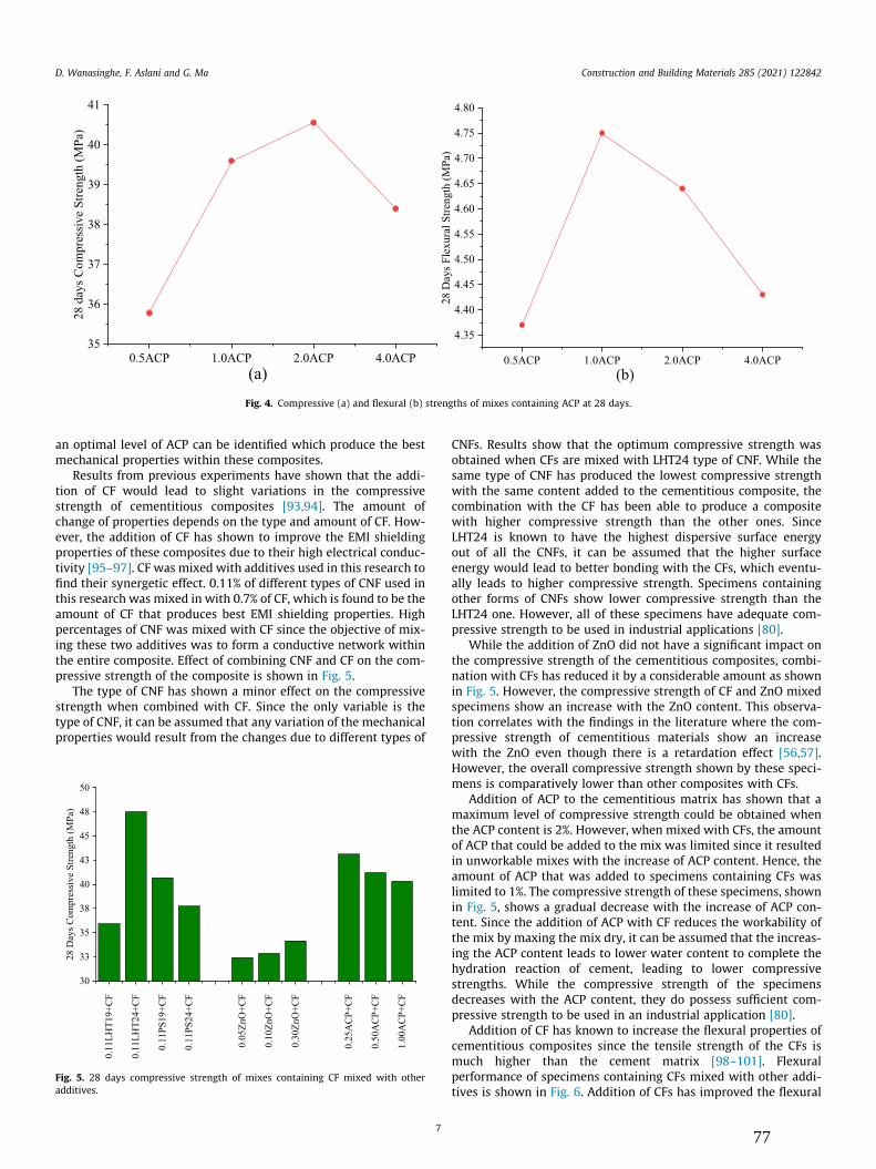
an optimal level of ACP can be identified which produce the bestmechanical properties within these composites.
Results from previous experiments have shown that the addi-tion of CF would lead to slight variations in the compressivestrength of cementitious composites [93,94]. The amount ofchange of properties depends on the type and amount of CF. How-ever, the addition of CF has shown to improve the EMI shieldingproperties of these composites due to their high electrical conduc-tivity [95–97]. CF was mixed with additives used in this research tofind their synergetic effect. 0.11% of different types of CNF used inthis research was mixed in with 0.7% of CF, which is found to be theamount of CF that produces best EMI shielding properties. Highpercentages of CNF was mixed with CF since the objective of mix-ing these two additives was to form a conductive network withinthe entire composite. Effect of combining CNF and CF on the com-pressive strength of the composite is shown in Fig. 5.
The type of CNF has shown a minor effect on the compressivestrength when combined with CF. Since the only variable is thetype of CNF, it can be assumed that any variation of the mechanicalproperties would result from the changes due to different types of
CNFs. Results show that the optimum compressive strength wasobtained when CFs are mixed with LHT24 type of CNF. While thesame type of CNF has produced the lowest compressive strengthwith the same content added to the cementitious composite, thecombination with the CF has been able to produce a compositewith higher compressive strength than the other ones. SinceLHT24 is known to have the highest dispersive surface energyout of all the CNFs, it can be assumed that the higher surfaceenergy would lead to better bonding with the CFs, which eventu-ally leads to higher compressive strength. Specimens containingother forms of CNFs show lower compressive strength than theLHT24 one. However, all of these specimens have adequate com-pressive strength to be used in industrial applications [80].
While the addition of ZnO did not have a significant impact onthe compressive strength of the cementitious composites, combi-nation with CFs has reduced it by a considerable amount as shownin Fig. 5. However, the compressive strength of CF and ZnO mixedspecimens show an increase with the ZnO content. This observa-tion correlates with the findings in the literature where the com-pressive strength of cementitious materials show an increasewith the ZnO even though there is a retardation effect [56,57].However, the overall compressive strength shown by these speci-mens is comparatively lower than other composites with CFs.
Addition of ACP to the cementitious matrix has shown that amaximum level of compressive strength could be obtained whenthe ACP content is 2%. However, when mixed with CFs, the amountof ACP that could be added to the mix was limited since it resultedin unworkable mixes with the increase of ACP content. Hence, theamount of ACP that was added to specimens containing CFs waslimited to 1%. The compressive strength of these specimens, shownin Fig. 5, shows a gradual decrease with the increase of ACP con-tent. Since the addition of ACP with CF reduces the workability ofthe mix by maxing the mix dry, it can be assumed that the increas-ing the ACP content leads to lower water content to complete thehydration reaction of cement, leading to lower compressivestrengths. While the compressive strength of the specimensdecreases with the ACP content, they do possess sufficient com-pressive strength to be used in an industrial application [80].
Addition of CF has known to increase the flexural properties ofcementitious composites since the tensile strength of the CFs ismuch higher than the cement matrix [98–101]. Flexuralperformance of specimens containing CFs mixed with other addi-tives is shown in Fig. 6. Addition of CFs has improved the flexural
0.5ACP 1.0ACP 2.0ACP 4.0ACP35
36
37
38
39
40
41
28 d
ays C
ompr
essi
ve S
treng
th (M
Pa)
(a)0.5ACP 1.0ACP 2.0ACP 4.0ACP
4.35
4.40
4.45
4.50
4.55
4.60
4.65
4.70
4.75
4.80
28 D
ays F
lexu
ral S
treng
th (M
Pa)
(b)
Fig. 4. Compressive (a) and flexural (b) strengths of mixes containing ACP at 28 days.
0.11
LHT1
9+C
F
0.11
LHT2
4+C
F
0.11
PS19
+CF
0.11
PS24
+CF
0.05
ZnO
+CF
0.10
ZnO
+CF
0.30
ZnO
+CF
0.25
AC
P+C
F
0.50
AC
P+C
F
1.00
AC
P+C
F
33
38
43
48
30
35
40
45
50
28 D
ays C
ompr
essi
ve S
treng
th (M
Pa)
Fig. 5. 28 days compressive strength of mixes containing CF mixed with otheradditives.
D. Wanasinghe, F. Aslani and G. Ma Construction and Building Materials 285 (2021) 122842
777

performance of mixes containing CNFs. Similar to the compressivestrength, the flexural strength has shown a maximum in the mixcontaining LHT24 CNFs. This again can be attributed to these fibresbonding with the CFs, which would result in a better fibre networkwhich would carry the applied load. While lower, specimens con-taining other types of CNFs have also shown an increase whencombined with CFs. Comparison of results with the specimens,which did not contain CFs show that they follow a similar pattern.
Combining CF with ZnO has resulted in only a minor improve-ment in the flexural strength of the specimens. While the flexuralstrength decreases with the addition of ZnO, the presence of CFprovides positive reinforcement. Even with the presence of CFs,these specimens show the lowest flexural strength out of all thespecimens containing CFs. The reason for this effect can be attrib-uted to the retarding effect of ZnO.
The mixing of ACP with CF produced mixes, which were dry andhard to be poured. Hence, the maximum amount of ACP, whichcould be mixed in with CF was limited to 1%. Even though the com-binations of these two additives resulted in mixes, which werehard to be handled, the water content was not changed since theobjective of this experiment was to assess the impact of additivesused within this research while keeping all other parameters con-stant. Previous tests showed that the flexural strength reached amaximum when the ACP content was 1%. When combined withCF the specimen with the same amount of ACP showed the bestflexural strength. The high flexural strength shown by this speci-men, in comparison to other specimens, is most likely due to thereduction of porosity when ACP is added to the cementitiousmatrix coupled with the reinforcement effect of CFs.
3.2. Electrical conductivity
The electrical conductivity of cementitious composites isknown to take place primarily due to the ionic conductivity. Inorder to have ionic conductivity, there should be a pore structurepresent within the material, since ions collect on the inside wallsof the pores [102–104]. Additives with high electrical conductivitysuch as CF and CNF could increase the overall conductivity of thecementitious composites. While CNF is known to have good elec-trical conductive properties, the addition of it in cementitious com-posites has shown no improvement for the electrical conductivityof the composite. In fact, the resistivity has shown an increase withthe increase of the CNF content, which can be seen from Fig. 7. Oneof the reasons for this behaviour could be the reduction of the porestructure within the matrix due to CNF occupying them. In order to
obtain high conductivity with CNF, its content needs to be signifi-cantly higher. However, increasing the CNF also increases the costof production since CNF is an expensive additive. All of the mixescontaining CNF show that electrical conductivity increases withthe amount of CNF content.
Mixes containing ZnO shows a lower electrical resistivity thanany of the mixes containing individual additives, as shown inFig. 7. The electrical conductivity of these mixes shows a maximumat 0.1% ZnO and decreases with the increase of the additive. How-ever, the addition of ZnO has a profound effect on the mechanicalproperties of the mixes, and the amount that could be added waslimited. Since ZnO nanoparticles delay the hydration reaction ofcement, it could lead to a higher porous structure within thecementitious composite at 28 days since the space occupied bywater will be empty once the specimen is dried. Previous researchhave shown that the addition of ZnO would lead to increasing ofthe porosity in the cementitious composites, which is a criticalparameter for the ionic conductivity of cementitious composites[91]. This increased porosity would be the main reason for thehigher electrical conductivity of these specimens compared toothers.
Addition of ACP has shown that the electrical conductivityincreases up to 1.00% ACP and decreases with further addition, asshown in Fig. 7. While ACP is known to be a good electrical conduc-tor, the increased presence of these would lead to a reduction ofthe pore structure within the material [92,105]. With the porositydecreasing with the increase of the ACP content, the electricalresistivity of these specimens would also increase. Even thoughindividual ACP is a good electrical conductor, they are distributedwithin the matrix as discontinued particles, which does not createa conductive network. Additionally, since ACP is known to consistof nanopores within its structure, which would trap ions otherwisefree for ionic conductivity in these composites [76,77,106]. Thecombined effect of all these would result in these compositesincreasing their resistivity when the ACP content is increasedbeyond 1.00%.
Since previous research have shown that the addition of CF tocementitious composites enhances the electrical properties of thecomposites, combined effect of CF with additives used in thisresearch was also investigated. Electrical conductivity results forall the hybrid mixes are shown in Fig. 8.
Average electrical conductivity results show that CNF con-tributes positively to the overall electrical conductivity of the spec-imens. However, there are slight variations among the mixesconsisting of different types of CNFs. The increased electrical con-ductivity of mixes consisting of CNF and CF can occur mainly dueto the extended conductive network, which would take place asa result of the interaction of the conductive additives since bothCF and CNF are known to be good electrical conductors.
Addition of ZnO with CF in cementitious composites has shownthat the electrical resistivity reaches a maximum value when theZnO content is 0.10%. Variation of the electrical conductivity ofthese hybrid composite could be due to various reasons since theionic content, water for the hydration, and porosity all vary withthe ZnO [90,107,108]. While it could be assumed that the CF wouldform a conductive network within the composite, the variationscreated by the addition of ZnO could modify the overall conductiv-ity of these specimens.
ACP with the combination of CF is expected to create a betterelectrically conductive network within the cementitious compos-ites. While the majority of the conductivity is contributed by theCFs, ACP is expected to act as nodes that would extend the con-ducting network. However, the results of electrical conductivitytests show that resistivity reaches a maximum when the ACP con-tent is increased before reducing again. Previous mixes consistingof ACP also show that the electrical conductivity increases when
0.11
LHT1
9+C
F
0.11
LHT2
4+C
F
0.11
PS19
+CF
0.11
PS24
+CF
0.05
ZnO
+CF
0.10
ZnO
+CF
0.30
ZnO
+CF
0.25
AC
P+C
F
0.50
AC
P+C
F
1.00
AC
P+C
F
7
8
9
10
11
28 D
ays F
lext
ural
Stre
ngth
(MPa
)
Fig. 6. 28 days flexural strength of mixes containing CF mixed with other additives.
D. Wanasinghe, F. Aslani and G. Ma Construction and Building Materials 285 (2021) 122842
878

the ACP content is increased from 0.50 to 1.00%, which can beobserved in mixes consisting of CFs as well. This indicates thatthe same effect ACP had on the cementitious matrix take placeeven when the CFs are there. Higher percentages of ACP couldnot be tested since they resulted in mixes which were too dry.
3.3. EMI shielding
Addition of CNF does not show a significant impact on the EMIshielding. While there are slight variations among the SE when dif-ferent CNF are added, the overall effect of them remains consider-able low, as shown in Fig. 9. LHT19 type shows that the overall SEincreases with the CNF content and reducing after reaching a max-imum. While overall SE shows considerable variation at lower fre-quencies, the SE tend to get uniform as the frequency is increasing.
Variation of the reflection SE shows near-identical behaviour withmany of the curves overlapping each other.
Addition of LHT24 CNF shows that the SE increases with theaddition of CNF and reaching a maximum, as shown in Fig. 10. Fur-ther addition of CNF reduces the overall SE of the composite. How-ever, the optimum SE produced by the LHT24 shows a higheramount of SE compared to LHT19. One reason for this behaviourcould be the slightly higher amount of electrical conductivityshown by the composites containing LHT24 CNFs. Overall SE ofthe mixes shows an increase with the frequency with slight varia-tion among each other. The reflection SE curves show near-identical behaviour, much like LHT19 specimens with severalcurves overlapping each other.
PS19 CNF has shown slight improvement in total EMI SE withthe increase of the fibre content. However, it can be seen that atlower frequencies, the SE is lower when the CNF content is low,with an exemption at 0.03%. This variation could occur most likelydue to the variation of the porosity with the addition of CNF chang-ing the porosity of the specimens, which in turn alters the multiplereflection component. Refection component shows no significantvariation with the addition of CNF. Similar to other CNF mixes,some of the reflection curves overlap each other indicating thereis almost no variation in the reflection SE. Total and reflection SEof specimens containing PS19 CNF are shown in Fig. 11.
EMI SE of specimens containing PS24 CNF, shown in Fig. 12,shows a very small amount of variation in SE. Overall SE resultsshow that SE is better at lower frequencies with a higher amountof CNF. However, with the increase of the frequency SE shown byall the mixes show similar results. Reflection SE shows that themix with 0.03% CNF has slightly better reflection properties com-pared to other mixes. However, similar to other mixes with CNF,these also shows almost no variation among each other.
Addition of CNF to cement has shown that there is only a slightvariation in the SE. Majority of the variation occurs in the lowerfrequency band and with the increase of the frequency, almostall the mixes show near-identical SE behaviour. Results indicatethat the amount of CNF added do not create a proper conductive
0.01
LHT1
90.
03LH
T19
0.05
LHT1
90.
07LH
T19
0.09
LHT1
90.
11LH
T19
0.01
LHT2
40.
03LH
T24
0.05
LHT2
40.
07LH
T24
0.09
LHT2
40.
11LH
T24
0.01
PS19
0.03
PS19
0.05
PS19
0.07
PS19
0.09
PS19
0.11
PS19
0.01
PS24
0.03
PS24
0.05
PS24
0.07
PS24
0.09
PS24
0.11
PS24
0.05
ZnO
0.10
ZnO
0.30
ZnO
0.5A
CP
1.0A
CP
2.0A
CP
4.0A
CP
1000
10000
Elec
trica
l Res
istiv
ity (k
cm)
Fig. 7. Electrical resistivity of initial mixes.
0.11
LHT1
9+C
F
0.11
LHT2
4+C
F
0.11
PS19
+CF
0.11
PS24
+CF
0.05
ZnO
+CF
0.10
ZnO
+CF
0.30
ZnO
+CF
0.25
AC
P+C
F
0.50
AC
P+C
F
1.00
AC
P+C
F
0.00
0.05
0.10
0.15
0.20
0.25
0.30
0.35
0.40
Elec
trica
l Res
istiv
ity (k
cm)
Fig. 8. Electrical conductivity of hybrid mixes.
D. Wanasinghe, F. Aslani and G. Ma Construction and Building Materials 285 (2021) 122842
979

0.2 0.4 0.6 0.8 1.0 1.2 1.4
-2
0
2
Tota
l EM
I SE
(dB
)
Frequency (GHz)
0.01LHT19 0.03LHT19 0.05LHT19 0.07LHT19 0.09LHT19 0.11LHT19
(a)
0.2 0.4 0.6 0.8 1.0 1.2 1.4-15
-10
-5
0
Ref
lect
ion
EMI S
E (d
B)
Frequency (GHz)
0.01LHT19 0.03LHT19 0.05LHT19 0.07LHT19 0.09LHT19 0.11LHT19
(b)
Fig. 9. Total (a) and reflection (b) EMI SE of mixes containing LHT19 CNF.
0.2 0.4 0.6 0.8 1.0 1.2 1.4-2
-1
0
1
2
3
Tota
l EM
I SE
(dB
)
Frequency (GHz)
0.01LHT24 0.03LHT24 0.05LHT24 0.07LHT24 0.09LHT24 0.11LHT24
(a)
0.2 0.4 0.6 0.8 1.0 1.2 1.4
-10
-5
0R
efle
ctio
n EM
I SE
(dB
)
Frequency (GHz)
0.01LHT24 0.03LHT24 0.05LHT24 0.07LHT24 0.09LHT24 0.11LHT24
(b)
Fig. 10. Total (a) and reflection (b) EMI SE of mixes containing LHT24 CNF.
0.2 0.4 0.6 0.8 1.0 1.2 1.4
0
1
2
3
Tota
l EM
I SE
(dB
)
Frequency (GHz)
0.01PS19 0.03PS19 0.05PS19 0.07PS19 0.09PS19 0.11PS19
(a)
0.2 0.4 0.6 0.8 1.0 1.2 1.4
-10
-5
0
Ref
lect
ion
EMI S
E (d
B)
Frequency (GHz)
0.01PS19 0.03PS19 0.05PS19 0.07PS19 0.09PS19 0.11PS19
(b)
Fig. 11. Total (a) and reflection (b) EMI SE of mixes containing PS19 CNF.
D. Wanasinghe, F. Aslani and G. Ma Construction and Building Materials 285 (2021) 122842
1080

network within the composite that would lead to higher EMIshielding properties.
Being a piezoelectric material, ZnO is known to absorb EMwaves providing shielding from EMI [70,71,109–111]. However,the amount of ZnO that could be added to cementitious materialsis limited due to their retarding effect, which has been discussed inprevious sections. EMI shielding properties of cementitious com-posites containing ZnO fabricated in this research are shown inFig. 13. At first glance, it can be seen that these specimens haveproduced a very small amount of EMI shielding properties. How-ever, the increase of the ZnO has shown an increase in both thereflection and overall shielding properties. While there is a consid-erable increase in EMI shielding when the ZnO content wasincreased from 0.05 to 0.10%, the effect of further addition isinsignificant. Since a higher amount of ZnO could not be addeddue to specimens not having enough strength to be handled, theeffect of percentages higher than 0.30% was not investigated in thisresearch.
Previous research has shown that ACP possesses good electricalconductive properties, which would be beneficial for EMI shieldingas well [105,112–114]. However, when ACP is added to the cemen-titious matrix, the resultant composites showed only a slight vari-
ation in EMI SE. Specimens did show a general increase in EMIshielding with the increase of the ACP content, as shown inFig. 14. Since ACP is known to reduce the porosity of cementitiouscomposites, as discussed previously, the synergetic effect of addingACP into cementitious matrix would result in only a minor varia-tion in EMI shielding since porosity is also an important factor thatis necessary for multiple reflection component of EMI shieldingmechanism [115–117].
Since previous experiments have shown that CF mixed cemen-titious composites have very good EMI shielding properties, thecombination of additives used in this research with CFs was carriedout to investigate their synergetic effect. Combination of CF andCNF has shown a minor variation in their EMI shielding properties,as shown in Fig. 15. The highest amount of EMI shielding has beenproduced by the composite containing PS19 CNFs. The electricalconductivity of the same composite also shows the highest value,indicating that the combined electrical conductivity of CNF andCFs could be the main reason for this mix to show better shieldingproperties than the other mixes. The mix consisting of LHT24 andCF also shows a very similar EMI shielding behaviour. While thesame composite has shown a higher electrical resistivity in themixes consisting of CNF, the higher amount of EMI shielding
0.2 0.4 0.6 0.8 1.0 1.2 1.40
1
2
3
Tota
l EM
I SE
(dB
)
Frequency (GHz)
0.01PS24 0.03PS24 0.05PS24 0.07PS24 0.09PS24 0.11PS24
(a)
0.2 0.4 0.6 0.8 1.0 1.2 1.4
-20
-15
-10
-5
0
Ref
lect
ion
EMI S
E (d
B)
Frequency (GHz)
0.01PS24 0.03PS24 0.05PS24 0.07PS24 0.09PS24 0.11PS24
(b)
Fig. 12. Total (a) and reflection (b) EMI SE of mixes containing PS24 CNF.
0.2 0.4 0.6 0.8 1.0 1.2 1.4-1
0
1
2
3
Tota
l EM
I SE
(dB
)
Frequency (GHz)
0.05ZnO 0.10ZnO 0.30ZnO
(a)
0.2 0.4 0.6 0.8 1.0 1.2 1.4-15
-10
-5
0
Ref
lect
ion
EMI S
E (d
B)
Frequency (GHz)
0.05ZnO 0.10ZnO 0.30ZnO
(b)
Fig. 13. Total (a) and reflection (b) EMI SE of mixes containing ZnO.
D. Wanasinghe, F. Aslani and G. Ma Construction and Building Materials 285 (2021) 122842
1181

indicates that there might be more than one mechanism of shield-ing taking place in the hybrid specimens. Since CNF is randomlydistributed within the cement matrix and because they have differ-ent permittivity, they could generate a higher amount of multiplereflections. Mixes with other CNFs, show slightly lower shieldingproperties compared to these two mixes. However, the variationof EMI shielding is negligible at lower frequencies. Reflection prop-erties show near identical results for most of the mixes with LHT24showing slightly higher shielding while PS24 mix showing slightlylower properties.
Aim of combining ZnO with CF is to ensure that ZnO wouldabsorb EM waves that do not interact with CFs. EMI shieldingresults of these hybrid mixes are shown in Fig. 16. From theseresults, it can be seen that the mix with the best shielding is theone with 0.05% ZnO, which is the lowest amount of ZnO in thesemixes. Since ZnO showed retarding effect, the increased amountof ZnO would have resulted in specimens which have not beendensified, which may have resulted in higher shielding propertiesin the mix with the lower amount of ZnO. The lowest amount ofshielding is generated by the mix with 0.10% ZnO while the mixwith the highest amount of ZnO has generated a moderate amountof shielding. While a high amount of ZnO would result in retarda-
tion, it would also absorb EMwaves, increasing the EMI SE with theincrease of the ZnO content. Since the majority of SE in these spec-imens are generated by the CF present in them, the variationamong the mixes can be due to the absorption of the EM wavesfrom the ZnO as well as from the matrix. Reflection properties ofthe mixes show that the reflection of the EM waves reaches a max-imum when the amount of ZnO is 0.10% when mixed with CFs.However, the variation of EMI reflection among the mixes is verysmall.
ACP, which is known to have good electrical conductive proper-ties, was mixed in with CF to create a better conductive networkwithin the specimens and EMI shielding results are shown inFig. 17. However, electrical resistivity results show that exceptfor 0.25% of ACP, other percentages have considerably higher resis-tivity when mixed with CFs. EMI shielding results of specimensconsisting of ACP and CF show that the best shielding is producedby the mix containing 0.50% of ACP. Since ACP has good electricalconductivity property of its own, it has not been able to producea very high conductive network with the specimen at this percent-age. This leads to the conclusion that ACP would induce reflectionof EM waves which can also lead to multiple reflection mechanismwithin the specimens. This is corroborated by the EM wave reflec-
0.2 0.4 0.6 0.8 1.0 1.2 1.4
-2
0
2
Tota
l EM
I SE
(dB
)
Frequency (GHz)
0.5ACP 1.0ACP 2.0ACP 4.0ACP
(a)
0.2 0.4 0.6 0.8 1.0 1.2 1.4-15
-10
-5
0
Ref
lect
ion
EMI S
E (d
B)
Frequency (GHz)
0.5ACP 1.0ACP 2.0ACP 4.0ACP
(b)
Fig. 14. Total (a) and reflection (b) EMI SE of mixes containing ACP.
0.2 0.4 0.6 0.8 1.0 1.2 1.4
30
35
40
45
50
55
60
65
Tota
l EM
I SE
(dB
)
Frequency (GHz)
0.11PS19+CF 0.11LHT24+CF 0.11LHT19+CF 0.11PS24+CF
(a)
0.2 0.4 0.6 0.8 1.0 1.2 1.4-35
-30
-25
-20
-15
-10
-5
0R
efle
ctio
n EM
I SE
(dB
)
Frequency (GHz)
0.11PS19+CF 0.11LHT24+CF 0.11LHT19+CF 0.11PS24+CF
(b)
Fig. 15. Total (a) and reflection (b) EMI SE of hybrid mixes containing CF and CNF.
D. Wanasinghe, F. Aslani and G. Ma Construction and Building Materials 285 (2021) 122842
1282

tion results as the same mix shows better reflection propertiesthan the rest. This percentage shows the highest amount of EMIshielding in all the three compositions of ACP mixed with CFs.Comparison of these results with other combined mixes showsthat 0.50% ACP hybrid mix provides the best amount of EMI shield-ing for the frequency range used in this research.
3.4. SEM analysis
SEM analyses of all the additives were carried out to observe themorphology of each of the additives. Different magnifications hadto be used each of these specimens depending upon the size ofeach of the additives. Fig. 18 shows the SEM image of CNFs, whichshows that these fibres are agglomerated into clump forms. This isone of the reasons why they were subjected to ultrasonicationbefore being added to the cement mix. This would have ensuredthat these clumps would have been broken down and fibres wouldmix with other additives in the mix.
0.2 0.4 0.6 0.8 1.0 1.2 1.4
30
35
40
45
50
55
60
65
Tota
l EM
I SE
(dB
)
Frequency (GHz)
0.05ZnO+CF 0.10ZnO+CF 0.30ZnO+CF
(a)
0.2 0.4 0.6 0.8 1.0 1.2 1.4
-30
-20
-10
0
Ref
lect
ion
EMI S
E (d
B)
Frequency (GHz)
0.05ZnO+CF 0.10ZnO+CF 0.30ZnO+CF
(b)
Fig. 16. Total (a) and reflection (b) EMI SE of hybrid mixes containing CF and ZnO.
0.2 0.4 0.6 0.8 1.0 1.2 1.425
30
35
40
45
50
55
60
65
Tota
l EM
I SE
(dB
)
Frequency (GHz)
0.25ACP+CF 0.50ACP+CF 1.00ACP+CF
(a)
0.2 0.4 0.6 0.8 1.0 1.2 1.4
-35
-30
-25
-20
-15
-10
-5
0
Ref
lect
ion
EMI S
E (d
B)
Frequency (GHz)
0.25ACP+CF 0.50ACP+CF 1.00ACP+CF
(b)
Fig. 17. Total (a) and reflection (b) EMI SE of hybrid mixes containing CF and ACP.
Fig. 18. SEM image of CNF.
D. Wanasinghe, F. Aslani and G. Ma Construction and Building Materials 285 (2021) 122842
1383

Fig. 19 shows the SEM image of the ZnO particles. Data providedby the manufacturer showed that the average particle size of theseis 30 nm. SEM image shows that these particles are agglomeratedtogether to form clumps. As in CNFs, ultrasonication was necessaryto ensure that these clumps would be broken down and individualparticles would be mixed with other additives in the mix.
SEM image of ACP given in Fig. 20 shows that there is a wideparticle size distribution in ACP particles. Additionally, the imagealso shows that there is no specific shape for these particles. Beingelectrically conductive particles, they appear dark in SEM analysiscompared with other additives.
In addition to SEM analysis of individual additives, SEM analy-ses were carried out for cementitious specimens fabricated withthese additives. These images showed that individual additiveshad been distributed within the cementitious matrix in a randommanner. However, it was not possible to identify the distributionof ZnO in these images. This was mainly due to the fact that theseparticles were small and did not show a specific pattern whenobserved using a SEM. Additionally, since ZnO is not electricallyconductive, which is same as the cementitious matrix, there wasno contrast difference in these when compared to the matrix.The very small amount of ZnO used in these mixes also made it dif-ficult to identify these in the composite.
SEM analyses of specimens with CF mixed with additives usedin this research was also carried out to observe if these additiveswould interlace with CFs. Specimens with CNF and CF clearly show
the presence of both additives and interlacing with each other, asshown in Fig. 21. The image shows that the CNFs are distributedwithin the matrix in a random manner and also in contact withthe CFs, which is vital for the expansion of the electricallyconductive network.
SEM images of a specimen with ACP and CF shows that ACPparticles are considerably larger than in comparison with CFs.Since ACP has good electrical conductivity, it could be observedthat they are darker than the surrounding matrix, as shown inFig. 22. While this image does not show that CF and ACP are in con-tact with each other, EMI shielding results suggest that these twoare indeed in contact, which has resulted in good shielding proper-ties. Additionally, since ACP can be seen to be larger in comparisonto CFs, it can be assumed that several CFs could come into contactwith a single ACP, which would result in a very good electrical con-ductive network with each ACP acting as a node for multiple CFs.
As previously mentioned, distribution of ZnO could not beobserved in this SEM analysis since these particles were small insize and did not have significant contrast difference to the sur-rounding matrix. The small amount of ZnO added to these mixeswould also create problems in detecting them through SEManalysis.
Many of the SEM images of specimens show dense structurewith additives being distributed evenly within the matrix. Hence,it would be interesting to observe how these materials wouldperform when they are subjected to electromagnetic waves in
Fig. 19. SEM Image of ZnO.
Fig. 20. SEM Image of ACP.
Fig. 21. SEM image of specimen containing CF and CNF.
Fig. 22. SEM images of specimen containing CF and ACP.
D. Wanasinghe, F. Aslani and G. Ma Construction and Building Materials 285 (2021) 122842
1484

the terahertz frequency range especially since EMI SE results forthese specimens also increase with the increasing frequency.However, for the EMI shielding measurements on the terahertz fre-quency range, there are no well-established standards; hence,comparison of results with other research in the same frequencyrange would pose minor problems.
4. Conclusion
The effects of adding CNF, ZnO, and ACP on mechanical, electri-cal, and EMI SE properties in cementitious composites were inves-tigated extensively in this research. In addition to the effects ofindividual additives on these properties, the combined effects ofthese with CFs were also investigated. Based on the resultsobtained from these tests, the following conclusions can be drawn.
1. Addition of CNF does not impact the mechanical properties ofcementitious composites to a great extent. However, it can beseen that with the addition of CNFs, mechanical propertiesreach an optimal level before decreasing again. The amount ofCNFs for this optimal level depends on the type of CNF used.It can be seen that when CNFs are combined with CFs, the vari-ation of mechanical properties primarily depends on the type ofCNF, which in turn would depend on the surface energy of theseCNFs. Variation of electrical conductivity did not show anyrelatable pattern in specimens indicating that CNF did not con-tribute to electrical conductivity. When combined with CFs, theelectrical conductivity showed slightly similar behaviour tomechanical properties, which depended on the type of CNF.EMI shielding properties did not vary by a great deal when CNFsused by themselves. Hybrid specimens containing CNF and CFalso showed only a small variation. However, from the shieldingresults, it was possible to identify that PS19 CNF in combinationwith CF would produce the best EMI shielding in this set ofhybrid mixes.
2. Addition of ZnO has a retardation effect on cementitious com-posites, which conforms with findings of previous research.Compressive strength reached a maximum when the ZnO con-tent was 0.10% while the flexural strength showed a gradualreduction with the ZnO content. When combined with CFs,specimens showed an increase in compressive strength whilethe flexural strength reduced with the ZnO content. Electricalconductivity showed a maximum when the ZnO content was0.10%, which decreased with higher addition. Hybrid mixeswith CFs showed an opposite behaviour where the conductivitywas minimum when the ZnO content was 0.10%. Multiple fac-tors, such as the porosity variation, availability of water, andpresence of ions would be the cause of this behaviour. TheEMI shielding properties showed an increase with the ZnO con-tent and when combined with the CFs, the best shielding prop-erties were produced by the hybrid mix with 0.05% ZnO.
3. Specimens with ACP showed a maximum in compressive andflexural strengths when the ACP content is 2.0 and 1.0% respec-tively. Mixing with CFs showed a detrimental effect on the com-pressive strength while it helped to improve the flexuralstrength. Combining the two additives proved challenging asthe mixes became unworkable when the ACP content wasincreased beyond 1.0% when combined with CFs. The electricalconductivity showed a maximumwhen the ACP content is 1.0%,while hybrid mixes with CFs showed a minimum value in theconductivity and slight increase thereafter. EMI shielding prop-erties showed a gradual increase with the ACP content. Whencombined with CFs, specimens showed a maximum amountof EMI shielding when the ACP content is 0.50%, which is thebest amount of shielding observed in this experiment.
Results obtained from experiments indicate that the combina-tion of additives used in this research with CFs has only a slightimprovement to EMI shielding properties. The amount of ZnOand ACP that could be added was limited due to loss of workabilityof the mixes, which also affected the EMI shielding.
CRediT authorship contribution statement
Dimuthu Wanasinghe: Conceptualization, Data curation, For-mal analysis, Investigation, Methodology, Software, Validation,Visualization, Writing - original draft. Farhad Aslani: Fundingacquisition, Supervision, Project administration, Resources, Con-ceptualization, Methodology, Data curation, Investigation, Visual-ization, Writing - review & editing. Guowei Ma: Fundingacquisition, Supervision, Writing - review & editing.
Declaration of Competing Interest
The authors declare that they have no known competing finan-cial interests or personal relationships that could have appearedto influence the work reported in this paper.
Acknowledgements
The authors would like to acknowledge the support by the Aus-tralian Research Council Discovery Project (Grant No.DP180104035).
References
[1] R.K. Funk, A.L. Stockham, N.N.I. Laack, Basics of radiation therapy, in: ClinicalCardio-Oncology, Elsevier, 2016, pp. 39–60.
[2] R. Percuoco, Plain radiographic imaging, in: Clinical Imaging, Elsevier, 2014,pp. 1–43.
[3] D.A. Elliott, N. Nabavizadeh, S.K. Seung, E.K. Hansen, J.M. Holland, Radiationtherapy, in: Oral, Head and Neck Oncology and Reconstructive Surgery,Elsevier, 2018, pp. 268–290.
[4] Scenihr, Possible effects of Electromagnetic Fields (EMF) on Human Health,Eur. Comm. Heal. Consum. Prot. Dir., no. July, p. 58, 2006.
[5] D.H. Pfluger, C.E. Minder, Effects of exposure to 16.7 Hz magnetic fields onurinary 6-hydroxymelatonin sulfate excretion of Swiss railway workers, J.Pineal Res. 21 (2) (1996) 91–100.
[6] J.H. Olsen, A. Nielsen, G. Schulgen, Residence near high voltage facilities andrisk of cancer in children, BMJ 307 (6909) (1993) 891–895.
[7] P.K. Verkasalo, E. Pukkala, J. Kaprio, K.V. Heikkila, M. Koskenvuo, Magneticfields of high voltage power lines and risk of cancer in Finnish adults:nationwide cohort study, BMJ 313 (7064) (1996) 1047–1051.
[8] M. Feychting, W.T. Kaune, D.A. Savitz, A. Ahlbom, Estimating exposure instudies of residential magnetic fields and cancer, Epidemiology 7 (3) (1996)220–224.
[9] A. Ahlbom et al., A pooled analysis of magnetic fields and childhoodleukaemia, Br. J. Cancer 83 (5) (2000) 692–698.
[10] B.D. Jankovic, D. Maric, J. Ranin, J. Veljic, Magnetic fields, brain and immunity:effect on humoral and cell-mediated immune responses, Int. J. Neurosci. 59(1–3) (1991) 25–43.
[11] Y.-J. Choi, Y.-S. Choi, Effects of electromagnetic radiation from smartphoneson learning ability and hippocampal progenitor cell proliferation in mice,Osong Public Heal. Res. Perspect. 7 (1) (2016) 12–17.
[12] R.C. Radha, P. Gurupranesh, Electromagnetic radiation from electronicappliances.
[13] V.F. Nikitin, N.N. Smirnov, M.N. Smirnova, V.V. Tyurenkova, On boardelectronic devices safety subject to high frequency electromagneticradiation effects, Acta Astronaut. 135 (2017) 181–186.
[14] W. Radasky, E. Savage, Intentional Electromagnetic Interference (IEMI) and ItsImpact on the U. S. Power Grid, Metatech Corporation, California, 2010.
[15] W.R. Graham et al., Report of the Commission to Assess the Threat to theUnited States from Electromagnetic Pulse (EMP) Attack - Critical NationalInfrastructures, Virginia, 2008.
[16] T. Williams, EMC, in: Instrumentation Reference Book, Elsevier, 2010, pp.797–871. no. November.
[17] T. Williams, Introduction, in: EMC for Product Designers, T. Williams, Ed.Elsevier, 1992, pp. 1–30.
[18] S. Rao, A. Sathyanarayanan, U.K. Nandwani, EMI problems for medicaldevices, Proc. Int. Conf. Electromagn. Interf. Compat. (1999) 21–24.
D. Wanasinghe, F. Aslani and G. Ma Construction and Building Materials 285 (2021) 122842
1585
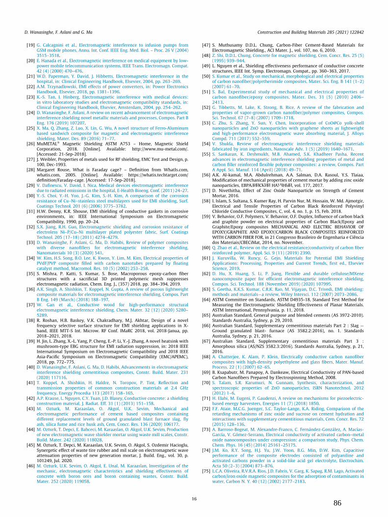
[19] G. Calcagnini et al., Electromagnetic interference to infusion pumps fromGSM mobile phones, Annu. Int. Conf. IEEE Eng. Med. Biol. – Proc. 26 V (2004)3515–3518.
[20] E. Hanada et al., Electromagnetic interference on medical equipment by low-power mobile telecommunication systems, IEEE Trans. Electromagn. Compat.42 (4) (2000) 470–476.
[21] W.D. Paperman, Y. David, J. Hibbetts, Electromagnetic interference in thehospital, in: Clinical Engineering Handbook, Elsevier, 2004, pp. 263–269.
[22] A.M. Trzynadlowski, EMI effects of power converters, in: Power ElectronicsHandbook, Elsevier, 2018, pp. 1381–1396.
[23] K.-S. Tan, I. Hinberg, Electromagnetic interference with medical devices:in vitro laboratory studies and electromagnetic compatibility standards, in:Clinical Engineering Handbook, Elsevier, Amsterdam, 2004, pp. 254–262.
[24] D. Wanasinghe, F. Aslani, A review on recent advancement of electromagneticinterference shielding novel metallic materials and processes, Compos. Part BEng. 176 (2019) 107207.
[25] X. Ma, Q. Zhang, Z. Luo, X. Lin, G. Wu, A novel structure of Ferro-Aluminumbased sandwich composite for magnetic and electromagnetic interferenceshielding, Mater. Des. 89 (2016) 71–77.
[26] MuMETAL� Magnetic Shielding ASTM A753 – Home, Magnetic ShieldCorporation, 2018. [Online]. Available: http://www.mu-metal.com/.[Accessed: 21-Sep-2018].
[27] J. Weibler, Properties of metals used for RF shielding, EMC Test and Design, p.100, Dec-1993.
[28] Margaret Rouse, What is Faraday cage? – Definition from WhatIs.com,whatis.com, 2005. [Online]. Available: https://whatis.techtarget.com/definition/Faraday-cage. [Accessed: 17-Sep-2018].
[29] V. Dafinescu, V. David, I. Nica, Medical devices electromagnetic interferencedue to radiated emissions in the hospital, E-Health Bioeng. Conf. (2011) 24–27.
[30] Y.-S. Choi, Y.-H. Yoo, J.-G. Kim, S.-H. Kim, A comparison of the corrosionresistance of Cu–Ni–stainless steel multilayers used for EMI shielding, Surf.Coatings Technol. 201 (6) (2006) 3775–3782.
[31] H.W. Denny, K.R. Shouse, EMI shielding of conductive gaskets in corrosiveenvironments, in: IEEE International Symposium on ElectromagneticCompatibility, 1990, pp. 20–24.
[32] S.X. Jiang, R.H. Guo, Electromagnetic shielding and corrosion resistance ofelectroless Ni–P/Cu–Ni multilayer plated polyester fabric, Surf. CoatingsTechnol. 205 (17–18) (2011) 4274–4279.
[33] D. Wanasinghe, F. Aslani, G. Ma, D. Habibi, Review of polymer compositeswith diverse nanofillers for electromagnetic interference shielding,Nanomaterials 10 (3) (2020) 541.
[34] W. Kim, H.S. Song, B.O. Lee, K. Kwon, Y. Lim, M. Kim, Electrical properties ofPVdF/PVP composite filled with carbon nanotubes prepared by floatingcatalyst method, Macromol. Res. 10 (5) (2002) 253–258.
[35] S. Mishra, P. Katti, S. Kumar, S. Bose, Macroporous epoxy-carbon fiberstructures with a sacrificial 3D printed polymeric mesh suppresseselectromagnetic radiation, Chem. Eng. J., (357) 2018, pp. 384–394, 2019.
[36] A.K. Singh, A. Shishkin, T. Koppel, N. Gupta, A review of porous lightweightcomposite materials for electromagnetic interference shielding, Compos. PartB Eng. 149 (March) (2018) 188–197.
[37] W. Gan et al., Conductive wood for high-performance structuralelectromagnetic interference shielding, Chem. Mater. 32 (12) (2020) 5280–5289.
[38] R. Roshan, H.B. Baskey, V.K. Chakradhary, M.J. Akhtar, Design of a novelfrequency selective surface structure for EMI shielding applications in X-band, IEEE MTT-S Int. Microw. RF Conf. IMaRC 2018, vol. 2018-Janua, pp.2018–2021, 2018.
[39] H. Jin, L. Zhang, X.-L. Yang, P. Cheng, E.-P. Li, Y.-J. Zhang, A novel heatsink withmushroom-type EBG structure for EMI radiation suppression, in: 2018 IEEEInternational Symposium on Electromagnetic Compatibility and 2018 IEEEAsia-Pacific Symposium on Electromagnetic Compatibility (EMC/APEMC),2018, pp. 772–775.
[40] D. Wanasinghe, F. Aslani, G. Ma, D. Habibi, Advancements in electromagneticinterference shielding cementitious composites, Constr. Build. Mater. 231(2020) 117116.
[41] T. Koppel, A. Shishkin, H. Haldre, N. Toropov, P. Tint, Reflection andtransmission properties of common construction materials at 2.4 GHzfrequency, Energy Procedia 113 (2017) 158–165.
[42] A.P. Krause, L. Nguyen, C.Y. Tuan, J.D. Blasey, Conductive concrete: a shieldingconstruction material, J. Radiat. Eff. 31 (1) (2013) 151–158.
[43] M. Ozturk, M. Karaaslan, O. Akgol, U.K. Sevim, Mechanical andelectromagnetic performance of cement based composites containingdifferent replacement levels of ground granulated blast furnace slag, flyash, silica fume and rice husk ash, Cem. Concr. Res. 136 (2020) 106177.
[44] M. Ozturk, T. Depci, E. Bahceci, M. Karaaslan, O. Akgol, U.K. Sevim, Productionof new electromagnetic wave shielder mortar using waste mill scales, Constr.Build. Mater. 242 (2020) 118028.
[45] M. Ozturk, T. Depci, M. Karaaslan, U.K. Sevim, O. Akgol, S. Ozdemir Hacioglu,Synergetic effect of waste tire rubber and mil scale on electromagnetic waveattenuation properties of new generation mortar, J. Build. Eng., vol. 30, p.101249, Jul. 2020.
[46] M. Ozturk, U.K. Sevim, O. Akgol, E. Unal, M. Karaaslan, Investigation of themechanic, electromagnetic characteristics and shielding effectiveness ofconcrete with boron ores and boron containing wastes, Constr. Build.Mater. 252 (2020) 119058.
[47] S. Muthusamy D.D.L. Chung, Carbon-Fiber Cement-Based Materials forElectromagnetic Shielding., ACI Mater. J., vol. 107, no. 6, 2010.
[48] Z. Shi, D.D.L. Chung, Concrete for magnetic shielding, Cem. Concr. Res. 25 (5)(1995) 939–944.
[49] L. Nguyen et al., Shielding effectiveness performance of conductive concretestructures, IEEE Int. Symp. Electromagn. Compat., pp. 360–363, 2017.
[50] S. Kumar et al., Study on mechanical, morphological and electrical propertiesof carbon nanofiber/polyetherimide composites, Mater. Sci. Eng. B 141 (1–2)(2007) 61–70.
[51] S. Bal, Experimental study of mechanical and electrical properties ofcarbon nanofiber/epoxy composites, Mater. Des. 31 (5) (2010) 2406–2413.
[52] G. Tibbetts, M. Lake, K. Strong, B. Rice, A review of the fabrication andproperties of vapor-grown carbon nanofiber/polymer composites, Compos.Sci. Technol. 67 (7–8) (2007) 1709–1718.
[53] C. Zhu, S. Zhang, Y. Sun, Y. Chen, Incorporation of CoO@Co yolk-shellnanoparticles and ZnO nanoparticles with graphene sheets as lightweightand high-performance electromagnetic wave absorbing material, J. AlloysCompd. 711 (2017) 552–559.
[54] V. Shukla, Review of electromagnetic interference shielding materialsfabricated by iron ingredients, Nanoscale Adv. 1 (5) (2019) 1640–1671.
[55] S. Sankaran, K. Deshmukh, M.B. Ahamed, S.K. Khadheer Pasha, Recentadvances in electromagnetic interference shielding properties of metal andcarbon filler reinforced flexible polymer composites: a review, Compos. PartA Appl. Sci. Manuf. 114 (April) (2018) 49–71.
[56] A.K. Al-kamal, M.A. Abdulrehman, A.A. Salman, D.A. Rasoul, Y.S. Tlaiaa,Modification of mechanical properties of cement mortar by adding zinc oxidenanoparticles, EBPAPBQCRBQ HAEXHSQ, vol. 177, 2017.
[57] D. Nivethitha, Effect of Zinc Oxide Nanoparticle on Strength of CementMortar, 2016.
[58] I. Islam, S. Sultana, S. Kumer Ray, H. Parvin Nur, M. Hossain, W. Md. Ajmotgir,Electrical and Tensile Properties of Carbon Black Reinforced PolyvinylChloride Conductive Composites, C, vol. 4, no. 1, p. 15, Feb. 2018.
[59] V. Behavior, O.F. Polymers, V. Behavior, O.F. Duplex, Influence of carbon blackand graphite powder on electrical properties of Carbon Black/Epoxy andGraphite/Epoxy composites MECHANICAL AND ELECTRIC BEHAVIOR OFEPOXY/GRAPHITE AND EPOXY/CARBON BLACK COMPOSITES REINFORCEDWITH CARBON FIBER FOR, in 21 Congresso Brasileiro de Engenharia e Ciênciados Materiais/CBECiMat, 2014, no. November.
[60] Q. Zhao et al., Review on the electrical resistance/conductivity of carbon fiberreinforced polymer, Appl. Sci. 9 (11) (2019) 2390.
[61] J. Kuruvilla, W. Runcy, G. Gejo, Materials for Potential EMI ShieldingApplications: Processing, Properties and Current Trends, first ed., ElsevierScience, 2019.
[62] D. Hu, X. Huang, S. Li, P. Jiang, Flexible and durable cellulose/MXenenanocomposite paper for efficient electromagnetic interference shielding,Compos. Sci. Technol. 188 (November 2019) (2020) 107995.
[63] S. Geetha, K.K.S. Kumar, C.R.K. Rao, M. Vijayan, D.C. Trivedi, EMI shielding:methods and materials—a review, Wiley Intersci. 112 (2007) 2073–2086.
[64] ASTM Committee on Standards, ASTM D4935-18, Standard Test Method forMeasuring the Electromagnetic Shielding Effectiveness of Planar Materials.ASTM International, Pennsylvania, p. 11, 2018.
[65] Australian Standard, General purpose and blended cements (AS 3972-2010).Standards Australia, Sydney, p. 29, 2010.
[66] Australian Standard, Supplementary cementitious materials Part 2 : Slag —Ground granulated blast- furnace (AS 3582.2:2016), no. 1. StandardsAustralia, Sydney, p. 21, 2016.
[67] Australian Standard, Supplementary cementitious materials Part 3 :Amorphous silica (AS/NZS 3582.3:2016). Standards Australia, Sydney, p. 21,2016.
[68] A. Chatterjee, K. Alam, P. Klein, Electrically conductive carbon nanofibercomposites with high-density polyethylene and glass fibers, Mater. Manuf.Process. 22 (1) (2007) 62–65.
[69] B. Ksapabutr, M. Panapoy, A. Dankeaw, Electrical Conductivity of PAN-basedCarbon Nanofibers Prepared by Electrospinning Method, 2008.
[70] S. Talam, S.R. Karumuri, N. Gunnam, Synthesis, characterization, andspectroscopic properties of ZnO nanoparticles, ISRN Nanotechnol. 2012(2012) 1–6.
[71] H. Elahi, M. Eugeni, P. Gaudenzi, A review on mechanisms for piezoelectric-based energy harvesters, Energies 11 (7) (2018) 1850.
[72] F.F. Ataie, M.C.G. Juenger, S.C. Taylor-Lange, K.A. Riding, Comparison of theretarding mechanisms of zinc oxide and sucrose on cement hydration andinteractions with supplementary cementitious materials, Cem. Concr. Res. 72(2015) 128–136.
[73] A. Barroso-Bogeat, M. Alexandre-Franco, C. Fernández-González, A. Macías-García, V. Gómez-Serrano, Electrical conductivity of activated carbon–metaloxide nanocomposites under compression: a comparison study, Phys. Chem.Chem. Phys. 16 (45) (2014) 25161–25175.
[74] J.M. Ko, R.Y. Song, H.J. Yu, J.W. Yoon, B.G. Min, D.W. Kim, Capacitiveperformance of the composite electrodes consisted of polyaniline andactivated carbons powder in a solid-like acid gel electrolyte, Electrochim.Acta 50 (2–3) (2004) 873–876.
[75] L.C.A. Oliveira, R.V.R.A. Rios, J.D. Fabris, V. Garg, K. Sapag, R.M. Lago, Activatedcarbon/iron oxide magnetic composites for the adsorption of contaminants inwater, Carbon N. Y. 40 (12) (2002) 2177–2183.
D. Wanasinghe, F. Aslani and G. Ma Construction and Building Materials 285 (2021) 122842
1686

[76] M. Inagaki, F. Kang, Engineering and Applications of Carbon Materials, inMaterials Science and Engineering of Carbon: Fundamentals, Elsevier, 2014,pp. 219–525.
[77] H. Marsh, F.R. Reinoso, Activated Carbon, 1st ed., Elsevier Science, 2006.[78] D. Wanasinghe, F. Aslani, G. Ma, Electromagnetic shielding properties of
carbon fibre reinforced cementitious composites, Constr. Build. Mater. 260(2020) 120439.
[79] D. Wanasinghe, F. Aslani, G. Ma, Effect of water to cement ratio, fly ash, andslag on the electromagnetic shielding effectiveness of mortar, Constr. Build.Mater. 256 (2020) 119409.
[80] Australian Standard, Concrete Structures (AS 3600:2018), StandardsAustralia, Sydney, 2018.
[81] R.N. Swamy, Fibre reinforcement of cement and concrete, Matériaux Constr. 8(3) (1975) 235–254.
[82] M.N. Soutsos, T.T. Le, A.P. Lampropoulos, Flexural performance of fibrereinforced concrete made with steel and synthetic fibres, Constr. Build.Mater. 36 (2012) 704–710.
[83] L. Brown, F. Sanchez, Influence of carbon nanofiber clustering on the chemo-mechanical behaviour of cement pastes, Cem. Concr. Compos. 65 (2016) 101–109.
[84] C. Gay, F. Sanchez, Performance of carbon nanofiber-cement composites witha high-range water reducer, Transp. Res. Rec. J. Transp. Res. Board 2142 (1)(2010) 109–113.
[85] T. Wang, J. Xu, B. Meng, G. Peng, Experimental study on the effect of carbonnanofiber content on the durability of concrete, Constr. Build. Mater. 250(2020) 118891.
[86] A. Peyvandi, L.A. Sbia, P. Soroushian, K. Sobolev, Effect of the cementitiouspaste density on the performance efficiency of carbon nanofiber in concretenanocomposite, Constr. Build. Mater. 48 (2013) 265–269.
[87] Y.L. Mo, R. Howser, Carbon nanofiber concrete for damage detection ofinfrastructure, Advances in Nanofibers, InTech, 2013.
[88] T. Manzur, N. Yazdani, M.A.B. Emon, Effect of carbon nanotube size oncompressive strengths of nanotube reinforced cementitious composites, J.Mater. 2014 (2014) 1–8.
[89] P. Siler et al., The effect of zinc, water to binder ratio and silica fume on thehydration and mechanical properties of Portland cement mixtures, IOP Conf.Ser. Mater. Sci. Eng. 583 (2019) 012008.
[90] Šiler et al., Application of isothermal and isoperibolic calorimetry to assessthe effect of zinc on hydration of cement blended with slag, Materials (Basel)12 (18) (2019) 2930.
[91] S. Ghahari, E. Ghafari, N. Lu, Effect of ZnO nanoparticles on thermoelectricproperties of cement composite for waste heat harvesting, Constr. Build.Mater. 146 (2017) 755–763.
[92] S. Aiswarya, M.T. Moses, L.B. Thomas, J. Scaria, G.V. Dev, Prospective benefitsof using activated carbon in cement composites- an overview, Int. J. Civ. Eng.Technol. 10 (04) (2019) 946–953.
[93] A. Briggs, Carbon fibre-reinforced cement, J. Mater. Sci. 12 (2) (1977) 384–404.
[94] D.D.L. Chung, Carbon Fiber Reinforced Concrete, Washington, DC, 1992.[95] P. Xie, P. Gu, J.J. Beaudoin, Electrical percolation phenomena in cement
composites containing conductive fibres, J. Mater. Sci. 31 (15) (1996) 4093–4097.
[96] N. Banthia, S. Djeridane, M. Pigeon, Electrical resistivity of carbon andsteel micro-fiber reinforced cements, Cem. Concr. Res. 22 (5) (1992) 804–814.
[97] X. Liu, Z. Nie, S. Wu, C. Wang, Self-monitoring application of conductiveasphalt concrete under indirect tensile deformation, Case Stud. Constr. Mater.3 (2015) 70–77.
[98] M.A. Ali, A.J. Majumdar, D.L. Rayment, Carbon fibre reinforcement of cement,Cem. Concr. Res. 2 (2) (1972) 201–212.
[99] H.A. Toutanji, T. El-Korchi, R.N. Katz, Strength and reliability of carbon-fiber-reinforced cement composites, Cem. Concr. Compos. 16 (1) (1994) 15–21.
[100] S.Akihama, T. Suenaga, T.Banno,Mechanicalpropertiesof carbonfibrereinforcedcement composites, Int. J. Cem. Compos. Light. Concr. 8 (1) (1986) 21–33.
[101] S.Y. Ghanem, J. Bowling, Mechanical properties of carbon-fiber–reinforcedconcrete, Adv. Civ. Eng. Mater. 8 (3) (2019) 20180089.
[102] K. Baldwin, Electrically conductive concrete: properties and potential, Constr.Canada 98 (1) (1998) 28–29.
[103] K. Venkatraman, V. Tamizharasan, Electrically conductive concrete, Int. J.Innov. Res. Sci. Eng. Technol. 4 (8) (2015) 6738–6743.
[104] A.S. El-Dieb, M.A. El-Ghareeb, M.A.H. Abdel-Rahman, E.S.A. Nasr,Multifunctional electrically conductive concrete using different fillers, J.Build. Eng., vol. 15, no. October 2017, pp. 61–69, Jan. 2018.
[105] T. Adinaveen, J.J. Vijaya, L.J. Kennedy, Comparative study of electricalconductivity on activated carbons prepared from various cellulosematerials, Arab. J. Sci. Eng. 41 (1) (2016) 55–65.
[106] A.F. Nicholas, M.Z. Hussein, Z. Zainal, T. Khadiran, Activated carbon for shape-stabilized phase change material, in: Synthesis, Technology and Applicationsof Carbon Nanomaterials, Elsevier, 2019, pp. 279–308.
[107] H. Bolio-Arceo, F.P. Glasser, Zinc oxide in cement clinkering: part 1. SystemsCaO—ZnO—Al2O3 and CaO—ZnO—Fe2O3, Adv. Cem. Res. 10 (1) (1998) 25–32.
[108] H. Bolio-Arceo, F.P. Glasser, Zinc oxide in Portland cement. Part II: hydration,strength gain and hydrate mineralogy, Adv. Cem. Res. 12 (4) (Oct. 2000) 173–179.
[109] A. Singh, Synthesis, characterization, electrical and sensing properties of ZnOnanoparticles, Adv. Powder Technol. 21 (6) (2010) 609–613.
[110] A. Samadi, S.M. Hosseini, M. Mohseni, Investigation of the electromagneticmicrowaves absorption and piezoelectric properties of electrospun Fe3O4-GO/PVDF hybrid nanocomposites, Org. Electron. 59 (2018) 149–155.
[111] A. Jain, P.K.J., A.K. Sharma, A. Jain, R.P.N, Dielectric and piezoelectricproperties of PVDF/PZT composites: a review, Polym. Eng. Sci., vol. 55, no.7, pp. 1589–1616, Jul. 2015.
[112] V. Hoffmann, C. Rodriguez Correa, D. Sautter, E. Maringolo, A. Kruse, Study ofthe electrical conductivity of biobased carbonaceous powder materials undermoderate pressure for the application as electrode materials in energystorage technologies, GCB Bioenergy 11 (1) (2019) 230–248.
[113] A. Celzard, J.F. Marêché, F. Payot, G. Furdin, Electrical conductivity ofcarbonaceous powders, Carbon N. Y. 40 (15) (2002) 2801–2815.
[114] E. Taer, M. Deraman, I.A. Talib, A.A. Umar, M. Oyama, R.M. Yunus, Physical,electrochemical and supercapacitive properties of activated carbon pelletsfrom pre-carbonized rubber wood sawdust by CO2 activation, Curr. Appl.Phys. 10 (4) (2010) 1071–1075.
[115] X.C. Tong, Advanced Materials and Design for Electromagnetic InterferenceShielding, 1st ed., CRC Press, Florida, 2009.
[116] C. Wang, J. Li, S. Guo, High-performance electromagnetic wave absorption bydesigning the multilayer graphene/thermoplastic polyurethane porouscomposites with gradient foam ratio structure, Compos. Part A Appl. Sci.Manuf. 125 (2019) 105522.
[117] Q. Liu, D. Zhang, T. Fan, Electromagnetic wave absorption properties ofporous carbon/Co nanocomposites, Appl. Phys. Lett. 93 (1) (2008) 013110.
D. Wanasinghe, F. Aslani and G. Ma Construction and Building Materials 285 (2021) 122842
1787

Chapter 6: Effect of electric arc furnace slag on electromagnetic shielding properties of
cementitious composites
Particles containing iron oxide is known to absorb the magnetic portion of the electromagnetic
waves. Electric arc furnace slag, being a by-product of iron manufacturing, is known to contain
iron and iron oxide. Hence, electric arc furnace slag was chosen to be added to cementitious
composite to study the effect on their own and in combination with CFs. In addition to electric
arc furnace slag, small aggregates of magnetite were also added to cementitious mixes to study
their effect on EMI shielding. Similar to electric arc furnace slag, magnetite aggregates are also
known to contain a high level of iron oxides in different forms. The effect of these two
aggregates was studied on their own in the cementitious composite as well as in combination
with CFs. The results showed slag aggregates had slightly better shielding properties when
added on their own since the amount of iron present in these is higher than in magnetite
aggregates. However, when mixed with CFs, both of these aggregates lowered the amount of
shielding produced by the composite by distorting the CF network and allowing the radiation
to pass through the material without encountering the fibre network. Slag aggregates produced
a maximum level of shielding of 34.21 dB when the aggregate content was 1.5 % and mixed
with the optimal amount of CFs. The maximum level of shielding produced by the magnetite
aggregates was 36.78 dB when the aggregate content was 1.5 % and in combination with CFs.
This chapter consists of the manuscript submitted for publication in “Construction and Building
Materials” and is currently under peer review and presented in the thesis in the submitted
format.
88

Effect of Electric Arc Furnace Slag and Heavy Weight Aggregates on Electromagnetic
Shielding Properties in Cementitious Composites
Abstract
Research into construction materials to be used as electromagnetic shielding has been on the
rise since it would allow eliminating the need to have metallic shields, which would cost more
and would require additional manufacturing. However, cement-based construction materials
are electrically insulating, making them transparent to electromagnetic radiation. The addition
of additives that would boost the electrical conductivity has been one of the main methods these
research have used to make cement-based material to act as shields against electromagnetic
radiation. This research looks at the effect of electric arc furnace slag and heavy-weight
aggregates on the electromagnetic shielding when added to cementitious composites along with
other properties such as mechanical and electrical conductivity. Four different weight
percentage of 0.5, 1.0, 1.5, and 2.0 of both aggregates were mixed into a control mix to assess
the effect of these aggregates on the electromagnetic interference shielding properties. Results
showed that optimal shielding was produced when both aggregate content was 1.5 % in their
respective mixes, which is 5.18 dB for electric arc furnace slag and 3.25 dB for heavy-weight
aggregate mixes, within the frequency range of 30 MHz to 1.5 GHz. However, the
improvement in shielding properties compared to the control was very small. Hence, these
aggregates were mixed with 0.7 % of carbon fibre mix, which has shown good shielding
properties to study the synergetic effect of all the additives. Several mix designs comprising
0.7 % of carbon fibre along with 1.0, 1.5, and 2.0 % of both types of aggregates were fabricated
and tested for shielding, mechanical, and electrical conducting properties. Electromagnetic
properties showed a gradual decrease with the aggregate content due to these aggregates
disrupting the conductive carbon fibre network within the specimens and enabling
electromagnetic radiation to pass through the specimens.
89

Keywords: electric arc furnace slag aggregates, heavy-weight aggregates, carbon fibre,
cementitious composites, electromagnetic shielding
1. Introduction
Electromagnetic (EM) waves consist of how frequency radio waves to high-frequency gamma
rays that exist in space [1], [2]. A very small fraction of these waves fall into the visible range,
commonly referred to as light. While EM radiations with a wide range of frequencies can be
found in nature, they could also be generated by manmade devices. The functionality of many
modern electronic devices results in the generation of EM radiation as a by-product. While
some of these radiations, such as radio waves, are useful for everyday life, others, such as high-
frequency microwaves, could disrupt the functionality of electronic devices, which is known
as electromagnetic interference (EMI) [3], [4]. Apart from disrupting other electronic devices,
high-frequency EM waves could also have an adverse effect on human health [3]–[9]. Various
methods have been investigated to provide shielding against EMI for a wide range of EM
radiation. While shielding could be adopted easily for small scale devices, it becomes
problematic for large scales, such as shielding in buildings. Traditionally, metals have been
used as EMI shielding material since they could create a Faraday's cage when irradiated with
EM waves due to their high electrical conductivity [10], [11]. However, this also means that
metal shields need to be developed for the building requiring shielding against EM radiation.
While metals are excellent in shielding EM radiation, they have inherent problems such as
corrosion, high manufacturing cost, and improper sealing [12]–[18]. One of the best ways to
overcome these problems is to develop an EM shielding construction material.
Cementitious composites have been the primary form of materials that have been used in the
construction industry for decades [19]. While there are ongoing research to replace cement with
more environmentally sustainable material, there is no material with the same properties as
cement [20], [21]. The innate electrical conductivity of cementitious composites is extremely
90

low, making them transparent to EM radiation. EMI shielding is generated in three different
ways: reflection, absorptions, and multiple reflections [11]. Materials, such as metals, which
have free moving charge carriers, are good at reflecting EM waves due to their high electrical
conductivity [22]. Interaction with material and EM radiation, which results in ohmic and heat
losses, is the main reason for the absorption losses [16]. Multiple reflection results when a
material consists of a large surface or interface area [22]. However, compared to the first two
mechanisms, shielding effectiveness (SE) created by the multiple reflection is very small [16].
For the measurement of SE, different techniques have been developed. These methods have
been developed based on the thickness of the material and the frequency range used for testing,
with each having advantages and limitations. Some of these techniques have been developed
to standards such as ASTM D4935 – 18, IEEE-STD-299, and MIL-STD-188-125-1 [23], [24].
Since cementitious materials are inherently electrically insulating, high conductive additives
are necessary to impart any form of electrical conductivity in these composites. However, these
various additives would also affect other properties sought after in these composites, such as
the compressive strength. Some of the most common additives which are being investigated
are steel fibres, carbon fibres (CF), carbon nanofiber, carbon nanotubes, and carbon powder
[25]–[32]. While these additives have been able to improve the EMI shielding properties in
cementitious composites, they still cannot reach the same level of SE as that of the metal
shields. This research aims to find the effect of electric arc furnace slag (EAFS) and heavy-
weight aggregates alone and in combination with carbon fibre (CF) on EMI shielding
properties.
EAFS is a by-product of the steel-making industry, which has been utilised in the cementitious
composite to replace natural aggregate [33], [34]. However, due to the lack of the same level
of strength in EAFS aggregates, the cementitious composite's compressive strength is known
to decrease with the addition of EAFS. The general chemical composition of EAFS aggregates
91

consists of Fe2O3, CaO, SiO2, Al2O3, and smaller percentages of other minerals [33]. The
presence of Fe2O3 is the primary reason why these aggregates could be used for EMI shielding.
CF is known to have excellent electrically conductive properties. The development of
manufacturing processes has reduced CF's cost, making them an affordable addition in
composite manufacturing [35]. EMI shielding properties of cementitious composites
containing CF have been studies in many previous research, which have shown a significant
increase in shielding when CF is added to the matrix [30], [36]–[38]. While CF produces good
EMI shielding properties in cementitious composites, this research also looks at the possible
synergetic effect of combining CF with EAFS.
2. Materials and methods
General-purpose cement was the primary binding material used for the fabrication of specimen
in this research. The cement used in this research conforms to the AS3972 (2010) standard
[39]. The chemical and physical properties of the cement provided by the manufacture is given
in Table 1, while an image of it in Figure 1(a).
Table 1: Chemical composition and physical properties of cement
Chemical composition Physical properties
CaO 63.40 % Specific gravity 3.0-3.2 t/m3
SiO2 20.10 % Fineness index 390 m2/kg
Al2O3 4.60 % Normal consistency 27 %
Fe2O3 2.80 % Setting time initial 120 min
SO3 2.70 % Setting time final 210 min
MgO 1.30 % Soundness 2 mm
Na2O 0.60 % Loss on ignition 3.80 %
Total chloride 0.02 % Residue 45 μm sieve 4.70 %
92

Sand with 45/50 grading and commonly used in industry was used as fine aggregates in the
fabrication of specimens. The chemical composition of the sand is given in Table 2 and an
image of it in Figure 1(b).
Table 2: Chemical composition of 45/50 sand
Chemical composition of silica Sand
SiO2 99.86 %
Fe2O3 0.01 %
Al2O3 0.02 %
CaO 0.00 %
MgO 0.00 %
Na2O 0.00 %
Ground-granulated blast-furnace slag (GGBFS) was also used in this research as a replacement
for general-purpose cement. GGBFS used in this research conforms to AS3582 standard, and
the chemical and physical properties of GGBFS provided by the manufacturer are given in
Table 3 and an image of it in Figure 1(c) [40]. While GGBFS also contains a small percentage
of iron oxide, primary constituents are very similar to that of cement, which is why they are a
good replacement for cement. The use of GGBFS as a cement replacement also increases the
environmental sustainability of the final product. However, since the composition of GGBFS
is not as same as that of cement, the maximum amount of it that can be added to the mix is
limited due to this reason.
93

Table 3: Chemical composition and physical properties of GGBFS
Chemical composition Physical properties
FeO 1.30 % Bulk density 850 kg/m3
CaO 38-43 % Glass content > 85 %
SiO2 32-37 % Angle of repose Approx. 35°
Al2O3 13-16 % Chloride ion < 0.025 %
MgO 5-8 %
TiO2 1.50 %
MnO 0.50 %
Hydraulic index 1.7-1.9 %
Silica fume is a common addition in the cementitious composite that is used to control bleeding.
The silica fume used in this research conforms to the AS3582 (2016) standard. The chemical
composition and physical properties of silica fume are given in Table 4 [41], while an image
is given in Figure 2(a).
Table 4: Chemical composition and physical properties of silica fume
Chemical composition Physical properties
Silicon as SiO2 98 % Bulk density 625 kg/m3
Sodium as Na2O 0.33 % Relative density 2.21
Potassium as K2O 0.17 % Pozzolanic activity at 7 days 111 %
Available alkali 0.40 % Control mix strength 31.3 MPa
Chloride as Cl- 0.15 % Moisture content 1.10 %
Sulphuric anhydride 0.83 % Loss of ignition 2.40 %
Sulphate as SO3 0.90 %
The effect of EAFS in combination with CF was also investigated in this research. Previous
research has shown that 0.7 % of 12 mm unsized CF can produce good level EMI shielding
properties when added to cementitious composites [36].
94

Figure 1: Images of (a) cement, (b) sand, and (c) GGBFS used in this research
A control mix was established in previous research, which produces the highest amount of EMI
shielding properties [42]. To investigate the effect EAFS has on EMI shielding properties,
different weight percentages of EAFS aggregates were added to fabricate different mixes while
keeping other additives constant. The image of the EAFS aggregates used in this research is
given in Figure 2(b). Chemical analysis carried out on these aggregates revealed that they
contain 6.97 % of Al2O3, 27.7 % of CaO, 34.3 % of Fe2O3, 9.34 % of MgO, 6.16 % of MnO,
and 12.5 % of SiO2. For the mixes containing EAFS and CF, all constituents, including CF,
were kept constant while the EAFS was varied. The objective of such a variation was to
determine the optimal amount of EAFS necessary to produce maximum EMI shielding in these
mixes. Heavy-weight (HW) aggregates commonly refer to minerals consisting of high
percentages of iron oxides, which are aggregates produced from iron ores. Some of the most
commonly used HW aggregates in cementitious composites are listed in ASTM C637−20
standard [43]. The specification provided by the HW aggregate supplier states that the size of
these aggregates is 1 – 2 mm, and they consist of 34.3% FeO. Compositions of the mixes
fabricated in this research are given in Table 5.
.
95

Table 5: Composition of mixes containing EAFS and HW aggregates
Label Cement GGBFS Sand
Silica
fume
EAFS
percentage
HW
percentage
CF percentage
Control 1.00 1.20 0.84 0.10 - - -
EAFS0.5 1.00 1.20 0.84 0.10 0.5 - -
EAFS1.0 1.00 1.20 0.84 0.10 1.0 - -
EAFS1.5 1.00 1.20 0.84 0.10 1.5 - -
EAFS2.0 1.00 1.20 0.84 0.10 2.0 - -
HW0.5 1.00 1.20 0.84 0.10 - 0.5 -
HW1.0 1.00 1.20 0.84 0.10 - 1.0 -
HW1.5 1.00 1.20 0.84 0.10 - 1.5 -
HW2.0 1.00 1.20 0.84 0.10 - 2.0 -
CF7+EAFS1.0 1.00 1.20 0.84 0.10 1.0 - 0.7
CF7+EAFS1.5 1.00 1.20 0.84 0.10 1.5 - 0.7
CF7+EAFS2.0 1.00 1.20 0.84 0.10 2.0 - 0.7
CF7+HW1.0 1.00 1.20 0.84 0.10 - 1.0 0.7
CF7+HW1.5 1.00 1.20 0.84 0.10 - 1.5 0.7
CF7+HW2.0 1.00 1.20 0.84 0.10 - 2.0 0.7
Figure 2: Images of (a) silica fume, (b) EAFS aggregates, and (c) HW aggregates used in this
research
Each of the mixes listed in Table 5 was cast to be tested in compression, flexural, electrical
conductivity, and EMI SE. For the compressive tests, three specimens with dimensions of 50
96

mm × 50 mm × 50 mm were cast and tested after 28 days. Values of each test specimen were
averaged to obtain the final value. For the flexural tests, three specimens with a length of 160
mm and a cross-sectional area of 40 mm × 40 mm were cast and tested after 28 days. Similar
to the compression test, each specimen's values were averaged to obtain the flexural strength
for the particular mix. The electrical conductivity of the mixes was measured using the four-
probe technique after 28 days of casting. Prior to measuring the conductivity, specimens were
dried at 110 ˚C for 24 hours to remove the free-standing water within the specimens. EMI SE
was measured according to ASTM D4935 – 18 standards. Hence, the dimensions of the
specimens were the same as that is mentioned in the standard. The thickness of the specimens
used for EMI shielding tests was 10 mm. Similar to electrical conductivity specimens, there
were also dried in an over at 110 C for 24 hours prior to testing. For both electrical conductivity
and EMI shielding tests, the average of three specimens was taken as the final reading.
3. Results and discussion
Variation of the compressive strength when EAFS are added is shown in Figure 3, along with
the compressive strength of the control mix. On average addition of EAFS has reduced the
compressive strength relative to the control mix. Compressive strength has shown the lowest
when the slag aggregate content is 1.5, while other mixes show slight variations among each
other. Macroscopic observations of EAFS aggregates of both sizes show that they are highly
porous, which can be observed in Figure 2(b) as well. Additionally, slag aggregates were light
in weight compared to natural aggregates used in concrete. The high porosity of these
aggregates leads to high brittleness, which would lower the overall compressive strength of the
fabricated mixes. However, the mix containing 1.5 % of EAFS shows much lower compressive
strength than other mixes. One possible reason for such a drop would be the low bonding of
the aggregates with the paste at this concentration leading to the specimen having lower
compressive strength.
97

While EAFS aggregates have brittle nature, HW aggregates do not show such behaviour upon
inspection. However, the addition of HW aggregates has led to even lower compressive
strength than the EAFS aggregates, as shown in Figure 3. The variation of the compressive
strengths of mixes containing HW aggregates shows similar behaviour to that of EAFS, with
HW aggregate specimens having much lower compressive strength for the same amount of
aggregates. While HW aggregates showed lesser porosity compared to EAFS aggregates, they
had comparatively even surface compared to irregular surfaces of EAFS aggregates. Having a
rough surface would lead to EAFS aggregates to have a much larger contact surface area than
the HW aggregates, leading to these specimens showing slightly higher compressive strength
values. The minimum compressive strength when the HW aggregate content is 1.5 % could be
due to poor adhesion between the aggregates and the paste at this content as the compressive
strength shown an increase similar to that of EAFS aggregate mixes.
Figure 3: 28-days compressive strength of the control and mixes containing different
percentages of EAFS and HW aggregates
98

The flexural strength of the fabricated mixes given in Figure 4 shows an increase when EAFS
aggregates are added to the mix. On average, the addition of the EAFS aggregates has increased
the flexural strength of the specimen. However, the flexural strength shows a maximum when
the aggregate content is 1.0 % and reduces thereafter.
Figure 4: 28-days flexural strength of the control and mixes containing different percentages
of EAFS and HW aggregates
Since the flexural strength of cementitious composites depends on the porosity of the
specimens, the increase of the flexural strength indicates a possible reduction in the pore size
in the specimens. The addition of a small amount of EAFS aggregates may have led to a
reduction of the pore sizes leading to flexural strength, reaching a maximum at 1.0 %. However,
further increase of the EAFS aggregate content would lead to increasing the pore sizes leading
to the gradual reduction of the flexural strength. The addition of HW aggregates has also shown
a maximum when the aggregate content of 1.0 % with slight variation in other mixes. As
99

observed previously, HW aggregates have smoother surfaces compared to EAFS aggregates,
which could lead to less variation of pore sizes hence flexural strength.
Being an electrically insulating material, cementitious composites are known to show a very
small amount of electrical conductivity due to ions present within the material. It has also been
proven that the pore structure within these materials plays a crucial role in the overall
conductivity [42]. The addition of any conducting material has known to improve the overall
conductivity of these materials. Electrical resistivity results of specimens containing EAFS and
HW aggregates are shown in Figure 5.
Figure 5: Resistivity of the control mix and mixes containing EAFS and HW aggregates
The addition of both types of aggregates has led to an increase in the resistivity of the
specimens, except for 1.0 % of EAFS and 1.5 % of HW. Both of these aggregates are known
to contain ions which would facilitate electrical conductivity. However, from these results, it
can be seen that the addition of these aggregates leads to modification of the pore structure
100

within the specimens that may lead to discontinued pores within the specimen. Since both the
pores and ions introduced by the aggregates can modify the conductivity of these mixes, it can
be concluded that the optimal amount of EAFS that could be added is limited to 1.0 %, while
the HW content is limited to 1.5 %, to obtain maximum conductivity.
While electrical conductivity is an essential parameter for EMI shielding, it is not the only
parameter that would contribute to EMI shielding of a material. Total EMI shielding generated
by a material is a combination of the three mechanisms described in the introductory section,
and the synergetic effects of additives would contribute to the total SE. EAFS and HW
aggregates are known to contain minerals that produce shielding against the magnetic portion
of the EMW at high frequencies [44], [45]. The addition of EAFS has shown to increase the
EMI SE to a maximum before reducing with a further increase, as shown in Figure 6. An
optimal amount of shielding of 5.18 dB has been produced by the mix containing a 1.5 %
amount of aggregates indicating that further addition of these aggregates would lead to
disruption of the material and would become transparent to EMW.
0.2 0.4 0.6 0.8 1.0 1.2 1.4-3
-2
-1
0
1
2
3
4
5
6
EM
I S
E (
dB
)
Frequency (GHz)
Control
EAFS 0.5%
EAFS 1.0%
EAFS 1.5%
EAFS 2.0%
(a)
0.2 0.4 0.6 0.8 1.0 1.2 1.4
-30
-25
-20
-15
-10
-5
0
Ref
lect
ion
EM
I S
E (
dB
)
Frequency (GHz)
Control
EAFS 0.5%
EAFS 1.0%
EAFS 1.5%
EAFS 2.0%
(b)
Figure 6: (a) total and (b) reflection EMI SE of mixes containing EAFS and the control mix
The addition of HW aggregates shows that the small addition of these aggregates does not
produce an adequate amount of shielding in these specimens, and the amount of shielding
101

increases with the aggregate content, as shown in Figure 7. An average maximum of shielding
of 3.25 dB is produced by the specimens containing 1.5 and 2.0 % of HW aggregates, indicating
that the addition of more than 1.5 % would not yield better shielding properties. The reflection
properties of these mixes show that the reflection of EMW reduces when the HW aggregate
content is increased beyond 1.5 %. This shows that the overall electrical conductivity of the
mixes would start to drop when the aggregate content is increased beyond 1.5 %. While both
EAFS and HW aggregates have been able to produce a certain level of EMI shielding, the
optimal amount of shielding produced by either of these aggregates remains very low. In order
to increase the overall EMI SE of these mixes, the addition of CF along with these two types
of aggregates was also researched. The CF type and amount were based on findings of previous
research [36].
0.2 0.4 0.6 0.8 1.0 1.2 1.4
-4
-3
-2
-1
0
1
2
3
4
EM
I S
E (
dB
)
Frequency (GHz)
Control
HW 0.5%
HW 1.0%
HW 1.5%
HW 2.0%
(a)
0.2 0.4 0.6 0.8 1.0 1.2 1.4
-45
-40
-35
-30
-25
-20
-15
-10
-5
0
Ref
lect
ion
EM
I S
E (
dB
)
Frequency (GHz)
Control
HW 0.5%
HW 1.0%
HW 1.5%
HW 2.0%
(b)
Figure 7: (a) total and (b) reflection EMI SE of mixes containing HW and the control mix
Previous research has shown that the addition of 12 mm CF does not significantly impact the
compressive strength of the cementitious composites and has enough strength to be used in
industrial applications [36]. However, the addition of 0.7 % CF has a significant impact on
EMI SE since CF is an excellent electrical conductor. The combination of CF with EAFS has
shown that the compressive strength of the mixes tends to decrease initially and increase when
the aggregate content is increased further, as shown in Figure 8. However, the compressive
102

strength of the mixes has not varied by a significant amount compared to the control mix. The
addition of HW aggregates into the mixes has shown to reduce the compressive strength by a
greater degree than EAFS, as shown in Figure 8. The compressive strength has shown to
increase with the increase of the HW aggregate content; however, it remains lower than the
compressive strength of the control mix. The reduction of the compressive strength due to the
addition of both type of aggregates is a sign that these aggregates weaken the bonding between
the additives, including CF and the cement paste. The increase of compressive strength with
the increase of the aggregates would be due to the higher compressive strength of the
aggregates.
Figure 8: 28-days compressive strength of the mixes containing CF along with EAFS and
HW aggregates
The variation of the flexural strength of the mixes containing EAFS aggregates shows similar
behaviour to that of the compressive strength, where the flexural strength first reduces and
increases with the further addition of aggregates. The addition of HW aggregates shows a much
103

higher reduction of the flexural strength compared to EAFS slag, as shown in Figure 9. The
flexural strength of composites containing CF is known to be governed by the tensile strength
of the CF within them. However, in order for such composite to have high flexural strength,
the majority of them need to be aligned in the direction of the applied stress. The pore size
within the material can also contribute to the flexural strength of these composites.
Additionally, the inclusion of CF is also known to increase the overall porosity of cementitious
composites since CF can trap air within them. As a result, variation of the flexural strength
obtained for these specimens could be due to all these factors in combination.
Figure 9: 28-days flexural strength of the mixes containing CF along with EAFS and HW
aggregates
The natal ionic conductivity in cementitious composites becomes negligible when CF is added
to them due to the high electrical conductivity of CF. However, to have this high conductivity
within the composite, the CF needs to have an interconnecting network. Disruption to this
network causes the conductivity of the specimen to decrease. The addition of a small amount
104

of EAFS aggregates has shown to increase the conductivity of these composite mixes, as shown
in Figure 10. This could be due to the contribution of constituents within the aggregates.
However, the increased addition of these aggregates has shown to decrease the conductivity,
which is most likely due to the disruption of the CF network within the mix. Mixes containing
HW aggregates also show similar behaviour but with lower conductivity than the mixes
containing the same amount of EAFS aggregates. These results show that the addition of both
types of aggregates in combination with CF needs to be kept at a low percentage to obtain an
optimal amount of electrical conductivity.
Figure 10: Resistivity of the mixes containing CF along with EAFS and HW aggregates
The inclusion of CF in the cementitious composites has shown a significant improvement in
the overall EMI SE. The primary reason for such an increase in the SE is the high electrical
conductivity of the CF, which produces a conductive network that interacts with the EMW and
attenuates them. The addition of both EAFS and HW aggregates has reduced the overall EMI
SE, as shown in Figure 11 and Figure 12, with a slight SE variation for the same amount of
105

aggregate content. It can also be seen that the EMI SE reduces with the increase of the aggregate
content for both. While both of these aggregates contain constituents that would aid in
producing EMI shielding, the overall SE is the synergetic effect of many factors such as the
additives within the composite, the electrical conductivity of the additives, distribution of the
additives, and porosity of the composites. The inclusion of these additives in these composites
can easily disrupt the distribution of CF enabling a higher percentage of EMW to go through
the material without interacting with the conductive network. As a result, increasing the
aggregate content has led to specimens having lower SE. The reduction of the conductivity
with the increasing aggregate content also shows that the conductive network breaks down with
the increasing aggregate contents, which is the primary reason for these mixes showing lower
SE. There are some research where these aggregates have been used for the fabrication of
concrete that would provide shielding against high-frequency radiation such as gamma rays,
the frequency range in this research was limited because of the fixture used for the EMI SE
measurement. This specific measurement technique was used in this research since it is known
that results obtained from this method are more repeatable and comparable than other
measurement techniques.
0.2 0.4 0.6 0.8 1.0 1.2 1.4
20
30
40
50
60
EM
I S
E (
dB
)
Frequency (GHz)
CF 0.7%
CF 0.7% + EAFS 1.0%
CF 0.7% + EAFS 1.5%
CF 0.7% + EAFS 2.0%
(a)
0.2 0.4 0.6 0.8 1.0 1.2 1.4-40
-35
-30
-25
-20
-15
-10
-5
0
Ref
lect
ion
EM
I S
E (
dB
)
Frequency (GHz)
CF 0.7%
CF 0.7% + EAFS 1.0%
CF 0.7% + EAFS 1.5%
CF 0.7% + EAFS 2.0%
(b)
Figure 11: (a) total and (b) reflection EMI SE of CF control and mixes containing different
percentages of EAFS aggregates
106

0.2 0.4 0.6 0.8 1.0 1.2 1.410
20
30
40
50
60
EM
I S
E (
dB
)
Frequency (GHz)
CF 0.7%
CF 0.7% + HW 1.0%
CF 0.7% + HW 1.5%
CF 0.7% + HW 2.0%
(a)
0.2 0.4 0.6 0.8 1.0 1.2 1.4
-35
-30
-25
-20
-15
-10
-5
0
Ref
lect
ion
EM
I S
E (
dB
)
Frequency (GHz)
CF 0.7%
CF 0.7% + HW 1.0%
CF 0.7% + HW 1.5%
CF 0.7% + HW 2.0%
(b)
Figure 12: (a) total and (b) reflection EMI SE of CF control and mixes containing different
percentages of HW aggregates
4. Conclusions
The primary objective of this research was to observe the effect of EAFS and HW aggregates
on the EMI shielding properties of cementitious composites within the 0.03 to 1.5 GHz
frequency range. For this purpose, different percentages of EAFS and HW aggregates were
mixed into a control mix and their mechanical, electrical conductivity, and EMI shielding
properties were measured after 28 days. Additionally, these aggregates were mixed in with
composite mixes that contained 0.7 % of CF since it has been found that CF produces good
EMI shielding properties when added to cementitious composites. Properties of these mixes
were also measured after 28 days, similar to that of previous mixes. Based on the results
obtained from these tests following conclusions can be drawn.
1. Both EAFS and HW aggregates showed a negative impact on the compressive strength
of the mixes, mainly due to poor compressive strength of the EAFS aggregates and low
bonding strength between the HW aggregates and the paste. Both types of aggregates
showed a minimum in compressive strength with the aggregate content and increased
beyond afterwards due to variation of the different mechanism controlling the
compressive strength. Mixes containing CF also showed a lowering of the compressive
107

strength with the addition of the aggregates. EAFS aggregate mixes showed a lowering
of compressive strength before increasing with the further addition of aggregates. The
addition of HW aggregates showed a gradual increase of the compressive strength with
the aggregate content; however, all of these mixes with HW aggregates had
compressive strength lower than the control mix.
2. Both aggregates showed an increase of flexural strength with small variation among
each mix. Variation of the pore sizes due to the addition of the aggregates is the main
reason for these variations. When combined with the CF, mixes showed much lower
flexural strength. CF having high tensile strength is the main reason for the control mix
with CF for having higher flexural strength. Hence, disruption to this CF within the
specimen due to the addition of aggregates has lowered the flexural strength. However,
EAFS with 2.0 % aggregates has shown higher flexural strength than any of the other
mixes. Such an increase would most likely due to the synergetic effect of porosity
modification and CF within the specimen. HW aggregates show very low flexural
strength compared to the control mix and increase with the aggregate content.
3. The addition of both types of aggregates showed a lowering of the electrical resistivity
in the specimen to a minimum value before increasing again. While constituents within
these aggregates can aid in electrical conductivity, the modification of the pores and the
pore structure would affect negatively in terms of conductivity. When added to
composites containing CF, the resistivity showed a gradual increase with the aggregate
content. Since the electrical conductivity of CF composites is governed by the
conductive network formed by the CF, the addition of a large amount of aggregates
disrupted the network causing the electrical resistivity to increase.
4. EMI shielding properties of the mixes containing EAFS and HW aggregates showed an
optimal level when the aggregate content is 1.5 %. However, this optimal level is a very
108

small increase when compared to the control mix. The mix containing 1.5 % of EAFS
aggregates produced a SE of 5.18 dB, while the mix with the same percentage of HW
aggregates produced a SE of 3.25 dB. Both aggregates were mixed with a control mix
containing 0.7 % of CF to study the synergetic effect on the overall EMI SE. However,
results showed that the addition of both types of aggregates leads to disruption of the
conducting network formed by the CF, which in turn reduces the overall SE with
aggregate addition.
5. Acknowledgements
The authors would like to acknowledge the support of the Australian Research Council
Discovery Project (Grant No.DP180104035).
6. References
[1] A. Smale, “Electromagnetic Spectrum - Introduction,” National Aeronautics and Space
Administration- Goddard Space Flight Center, 2013. [Online]. Available:
https://imagine.gsfc.nasa.gov/science/toolbox/emspectrum1.html. [Accessed: 12-Nov-
2020].
[2] T. Williams, “Introduction,” in EMC for Product Designers, T. Williams, Ed. Elsevier,
1992, pp. 1–30.
[3] C. BINGGELI et al., “Induction Ovens and Electromagnetic Interference: What Is the
Risk for Patients with Implantable Cardioverter Defibrillators?,” J. Cardiovasc.
Electrophysiol., vol. 16, no. 4, pp. 399–401, Apr. 2005.
[4] D. P. Sager, “Current facts on pacemaker electromagnetic interference and their
application to clinical care,” Hear. Lung; (United States).
[5] A. B. Lavanya, “Effects of electromagnetic radiation on biological systems: a short
review of case studies,” in 8th International Conference on Electromagnetic
109

Interference and Compatibility, 2003, vol. 2003-Janua, pp. 87–90.
[6] A. Zamanian and C. Hardiman, “Electromagnetic Radiation and Human Health: A
Review of Sources and Effects,” no. July, 2005.
[7] J. Boyle, “Wireless Technologies and Patient Safety in Hospitals,” Telemed. e-health,
vol. 12, no. 3, 2006.
[8] Y. Kawamura, T. Hikage, T. Nojima, K. Fukui, H. Fujimoto, and T. Toyoshima,
“Experimental estimation of EMI from electronic article surveillance on implantable
cardiac pacemakers and implantable cardioverter defibrillators: Interference distance
and clinical estimation,” Trans. Japanese Soc. Med. Biol. Eng., vol. 50, no. 3, pp. 289–
298, 2012.
[9] J. Higashiyama, Y. Tarusawa, T. Hikage, and T. Nojima, “EMI risk assessment of
electromagnetic field from mobile phone in elevator cabin for implantable pacemaker,”
2012 Int. Symp. Electromagn. Compat. (EMC Eur. 2012). Proc., 2012.
[10] D. Wanasinghe and F. Aslani, “A review on recent advancement of electromagnetic
interference shielding novel metallic materials and processes,” Compos. Part B Eng.,
vol. 176, p. 107207, Nov. 2019.
[11] S. Geetha, K. K. S. Kumar, C. R. K. Rao, M. Vijayan, and D. C. Trivedi, “EMI
Shielding: Methods and Materials—A Review,” Wiley Intersci., vol. 112, pp. 2073–
2086, 2007.
[12] A. Shishkin, T. Koppel, V. Mironov, I. Hussainova, J. Locs, and H. Haldre, “Microwave
Reflectance and Transmittance Properties of Conductive Composite Materials,” Energy
Procedia, vol. 113, pp. 354–361, May 2017.
[13] Y.-S. Choi, Y.-H. Yoo, J.-G. Kim, and S.-H. Kim, “A comparison of the corrosion
110

resistance of Cu–Ni–stainless steel multilayers used for EMI shielding,” Surf. Coatings
Technol., vol. 201, no. 6, pp. 3775–3782, Dec. 2006.
[14] H. W. Denny and K. R. Shouse, “EMI shielding of conductive gaskets in corrosive
environments,” in IEEE International Symposium on Electromagnetic Compatibility,
1990, pp. 20–24.
[15] S. X. Jiang and R. H. Guo, “Electromagnetic shielding and corrosion resistance of
electroless Ni–P/Cu–Ni multilayer plated polyester fabric,” Surf. Coatings Technol., vol.
205, no. 17–18, pp. 4274–4279, May 2011.
[16] X. C. Tong, Advanced Materials and Design for Electromagnetic Interference
Shielding, 1st ed. Florida: CRC Press, 2009.
[17] S. Y. Chang, S. K. A. Bahar, and J. Zhao, Advances in Civil Engineering and Building
Materials. CRC Press, 2012.
[18] J. Delmonte, Metal/Polymer Composites. Springer US, 2013.
[19] P. Jahren and T. Sui, History Of Concrete: A Very Old And Modern Material. Singapore:
World Scientific Publishing Company, 2017.
[20] H. Zain, M. M. A. B. Abdullah, K. Hussin, N. Ariffin, and R. Bayuaji, “Review on
Various Types of Geopolymer Materials with the Environmental Impact Assessment,”
in MATEC Web of Conferences, 2017, vol. 97, p. 01021.
[21] G. Habert and C. Ouellet-Plamondon, “Recent update on the environmental impact of
geopolymers,” RILEM Tech. Lett., vol. 1, p. 17, Apr. 2016.
[22] S. Sankaran, K. Deshmukh, M. B. Ahamed, and S. K. Khadheer Pasha, “Recent
advances in electromagnetic interference shielding properties of metal and carbon filler
reinforced flexible polymer composites: A review,” Compos. Part A Appl. Sci. Manuf.,
111

vol. 114, no. April, pp. 49–71, 2018.
[23] ASTM Committee on Standards, “ASTM D4935-18, Standard Test Method for
Measuring the Electromagnetic Shielding Effectiveness of Planar Materials.” ASTM
International, Pennsylvania, p. 11, 2018.
[24] Department of Defense, “MIL-STD-188-125-1 High-Altitude Electromagnetic (HEMP)
Protection for Ground Based C41 Facilities.” US Military Specs/Standards/Handbooks,
Virginia, p. 106, 2005.
[25] D. Wanasinghe, F. Aslani, G. Ma, and D. Habibi, “Advancements in electromagnetic
interference shielding cementitious composites,” Constr. Build. Mater., vol. 231, p.
117116, Jan. 2020.
[26] M. Sharif, C. S. Ping, and K. Y. Leong, “Electromagnetic Interference Shielding
Performances of MWCNT in Concrete Composites,” Diffusion and defect data., vol.
266, no. [ISS UE]. Sci-Tech Publications, [Vaduz, Liechtenstein :, pp. 283–286, 2017.
[27] A. Mazzoli et al., “Effect of graphene oxide and metallic fibers on the electromagnetic
shielding effect of engineered cementitious composites,” J. Build. Eng., vol. 18, no.
February 2017, pp. 33–39, 2018.
[28] S. K. Yee and M. Z. M. Jenu, “Shielding effectiveness of concrete with graphite fine
powder in between 50MHz to 400MHz,” 2013 Asia-Pacific Symp. Electromagn.
Compat. APEMC 2013, 2015.
[29] D. Micheli et al., “Electromagnetic characterization and shielding effectiveness of
concrete composite reinforced with carbon nanotubes in the mobile phones frequency
band,” Mater. Sci. Eng. B Solid-State Mater. Adv. Technol., vol. 188, pp. 119–129, 2014.
[30] S. Muthusamy and D. D. L. Chung, “Carbon-Fiber Cement-Based Materials for
112

Electromagnetic Shielding.,” ACI Mater. J., vol. 107, no. 6, 2010.
[31] A. P. Krause, L. Nguyen, C. Y. Tuan, and J. D. Blasey, “Conductive Concrete: a
Shielding Construction Material,” J. Radiat. Eff., vol. 31, no. 1, pp. 151–158, 2013.
[32] Z. Liu, H. Ge, J. Wu, and J. Chen, “Enhanced electromagnetic interference shielding of
carbon fiber/cement composites by adding ferroferric oxide nanoparticles,” Constr.
Build. Mater., vol. 151, pp. 575–581, 2017.
[33] S. Monosi, M. L. Ruello, and D. Sani, “Electric arc furnace slag as natural aggregate
replacement in concrete production,” Cem. Concr. Compos., vol. 66, pp. 66–72, Feb.
2016.
[34] S.-W. Kim, Y.-J. Lee, and K.-H. Kim, “Flexural Behavior of Reinforced Concrete
Beams with Electric Arc Furnace Slag Aggregates,” J. Asian Archit. Build. Eng., vol.
11, no. 1, pp. 133–138, May 2012.
[35] J. Meredith, E. Bilson, R. Powe, E. Collings, and K. Kirwan, “A performance versus
cost analysis of prepreg carbon fibre epoxy energy absorption structures,” Compos.
Struct., vol. 124, pp. 206–213, Jun. 2015.
[36] D. Wanasinghe, F. Aslani, and G. Ma, “Electromagnetic shielding properties of carbon
fibre reinforced cementitious composites,” Constr. Build. Mater., vol. 260, p. 120439,
Nov. 2020.
[37] D. D. . Chung, “Electromagnetic interference shielding effectiveness of carbon
materials,” Carbon N. Y., vol. 39, no. 2, pp. 279–285, Feb. 2001.
[38] D. D. L. Chung and A. A. Eddib, “Effect of fiber lay-up configuration on the
electromagnetic interference shielding effectiveness of continuous carbon fiber
polymer-matrix composite,” Carbon N. Y., vol. 141, 2018.
113

[39] Australian Standard, “General purpose and blended cements (AS 3972-2010).”
Standards Australia, Sydney, p. 29, 2010.
[40] Australian Standard, “Supplementary cementitious materials Part 2 : Slag — Ground
granulated blast- furnace (AS 3582.2:2016),” no. 1. Standards Australia, Sydney, p. 21,
2016.
[41] Australian Standard, “Supplementary cementitious materials Part 3 : Amorphous silica
(AS/NZS 3582.3:2016).” Standards Australia, Sydney, p. 21, 2016.
[42] D. Wanasinghe, F. Aslani, and G. Ma, “Effect of water to cement ratio, fly ash, and slag
on the electromagnetic shielding effectiveness of mortar,” Constr. Build. Mater., vol.
256, p. 119409, Sep. 2020.
[43] ASTM Committee on Standards, “ASTM C637−20, Standard specification for
aggregates for radiation-shielding concrete,” ASTM International, vol. 4, no. 100.
ASTM International, Pennsylvania, pp. 1–4, 2015.
[44] M. Oluwaseun Azeez, S. Ahmad, S. U. Al-Dulaijan, M. Maslehuddin, and A. Abbas
Naqvi, “Radiation shielding performance of heavy-weight concrete mixtures,” Constr.
Build. Mater., vol. 224, pp. 284–291, Nov. 2019.
[45] C. Basyigit et al., “Investigating Radiation Shielding Properties of Different Mineral
Origin Heavyweight Concretes,” in AIP Conference Proceedings, 2011, vol. 1400, pp.
232–235.
114

Chapter 7: An experimental and simulation-based study on the effect of carbonyl iron,
heavyweight aggregate powders, and carbon fibres on the electromagnetic shielding
properties of cement-based composites
Carbonyl iron powder (CIP) is known to have excellent EMI shielding properties since it
consists of pure iron and is commonly used for radar-absorbing paint manufacturing. Different
percentages of CIP was mixed into the control mix and the mix containing 0.7 wt% 12 mm
CFs to study their synergetic effect. Additionally, magnetite powder was also used in a similar
manner to study the effect on EMI shielding and compare results with specimens containing
CIP. In addition to these two powders, 3 mm CF was mixed with 12 mm CF to analyse the
amount of EMI shielding produced. The primary purpose of mixing the two different CFs was
to observe the possible change in EMI shielding due to the expansion of the conductive
network. However, results showed that EMI shielding properties could not be enhanced when
the two different CFs were mixed and the maximum level of EMI shielding produced was
limited to 50 dB when the 3 mm CF content was 0.1 %. On the other hand, CIP was able to
produce an EMI shielding of 51.30 dB when the powder content was 20 % and in combination
with 0.7 wt% 12 mm CF. Magnetite powder produced an EMI shielding of 46.15 dB for the
same amount of powder as CIP and in combination with CF. The paper has been included in
the thesis in the published format.
Wanasinghe, D., Aslani, F., & Ma, G. (2021). An experimental and simulation-based study on
the effect of carbonyl iron, heavyweight aggregate powders, and carbon fibres on the
electromagnetic shielding properties of cement-based composites. Construction and Building
Materials, 313, 125538. https://doi.org/10.1016/j.conbuildmat.2021.125538
115

Construction and Building Materials 313 (2021) 125538
0950-0618/© 2021 Elsevier Ltd. All rights reserved.
An experimental and simulation-based study on the effect of carbonyl iron, heavyweight aggregate powders, and carbon fibres on the electromagnetic shielding properties of cement-based composites
Dimuthu Wanasinghe , Farhad Aslani *, Guowei Ma Materials and Structures Innovation Group, School of Engineering, The University of Western Australia, WA, Australia
A R T I C L E I N F O
Keywords: Carbonyl iron Heavyweight aggregate Carbon fibre Cement composite
A B S T R A C T
Research into electromagnetic interference (EMI) shielding has been growing over the last couple of decades due to shortcomings of existing methods and increased demand. Therefore, the construction industry has also been interested in fabricating a cement-based composite that could be used for EMI shielding without the use of additional cladding material. This research is focused on fabricating a cement-based composite that could be used for EMI shielding with the addition of carbonyl iron powder, heavyweight aggregate powder, and carbon fibres. Several mix designs were carried out by varying the additives used to find the content that would produce optimal properties. All the mixes were tested for their mechanical, electrical conductivity, and EMI shielding properties. EMI shielding tests were carried out per ASTM D4935 – 18 standard within 30 MHz to 1.5 GHz frequency range. The mix consisting of 20% carbonyl iron powder in combination with 0.7% of 12 mm CF produced an EMI shielding of 51.30 dB, which was the best result obtained for any mix in this research. An additional simulation was carried out using CST Studio software to see the theoretical level of shielding produced by these mixes. The simulation results showed near identical results to that of the experimental with smaller variation at specific frequencies.
1. Introduction
Electromagnetic radiation (EMR) is the most common form of radi-ation that could be found in nature [1]. As per the theory, EMR has electrical and magnetic fields, which are normal to each other, and they could induce electrical current in an electrical conductor [2]. This effect is known as electromagnetic interference (EMI) and could cause adverse effects in sensitive electronic devices [3]. This phenomenon can be observed in nature during a lightning storm, where high electrical cur-rents are generated in overhead powerlines. The same effect created by artificial EMR is known to be used as weapons, for espionage, and known to cause problems in critical care and human health [4–12]. Hence, it is important to have an adequate level of shielding against EMI. The theory of EMI shielding explains that there are three methods of shielding known as reflection, absorption, and multiple reflection [13]. Materials that are known to be excellent EMI shields are also good electrical conductors such as metals [14]. Drawbacks of existing metallic shields and innovation of new materials have increased the number of research on EMI shielding materials in the past couple of decades, as shown in
Fig. 1. Many of these research on to EMI shielding composites have attempted to impart electrical conductivity in traditionally insulating materials. In addition to additives that would impart electrical con-ductivity, some additives could also absorb EMR, which would add to the overall shielding effectiveness (SE) of the composite. Despite having an increased number of research in the field of EMI shielding compos-ites, research on EMI shielding cement-based materials remain relatively low, as shown in Fig. 1. One of the main reasons for this is that cement- based composites are electrically insulating and inherently transparent to EMR. Recent developments of EMI shielding cementitious composites as well as the theory of shielding are explained in detail in many prior publications [15,16].
This research is looking into the fabrication of cement-based com-posite for EMI shielding since cement is the most common material that is used in the construction industry. EMI shielding of buildings has shown that the effectiveness of existing metal shields degrades over time, mainly due to corrosion. Additionally, metal shields are expensive to produce and could leak EMR through gaps between each cladding. Having a construction material that can shield EMR can avoid all the
* Corresponding author at: Materials and Structures Innovation Group, School of Engineering, The University of Western Australia, WA, Australia E-mail address: [email protected] (F. Aslani).
Contents lists available at ScienceDirect
Construction and Building Materials
journal homepage: www.elsevier.com/locate/conbuildmat
https://doi.org/10.1016/j.conbuildmat.2021.125538 Received 14 July 2021; Received in revised form 21 October 2021; Accepted 1 November 2021
116

Construction and Building Materials 313 (2021) 125538
2
drawbacks of metal shields. To make cement an EMI shielding material, additives that can impart electrical conductivity or directly absorb EMR would be needed since cement is an inherent electrical insulator. Pre-vious research showed that a high level of shielding could be achieved by the addition of carbon fibre (CF) into cement-based composites [17]. Apart from CFs, previous research also revealed that other additives could contribute to overall EMI SE by either directly interacting with EMR or by modifying the structure of the material that would increase interactions with EMR [18]. This research is focused on enhancing the EMI shielding properties obtained in prior research with the use of conductive and EMR absorbing materials.
Inclusion of many of the additives that would impart EMI shielding properties also leads to a reduction in mechanical properties of cement- based composites. Hence, the amount and type of additives that could be added to these composites are very limited. Therefore, the additives used for EMI shielding need to have good properties in attenuating EMR either by absorption or reflection. It is known that materials with a high amount of iron or iron oxides can absorb EMR, increasing the overall SE of composites [19,20]. Hence, this research focused on using additives that are rich in iron content and are known to be good EMI shielding materials. Additionally, this research attempted to enhance the results obtained in previous research by expanding the conductive network within the composite by combining CFs with different lengths.
Measurement of the amount of shielding produced by a material can be measured in several different ways depending upon the frequency range used and the size of the component. Some of these methods have been standardised so that the results can be compared with other research. Some of such notable standards include, ASTM E1851 – 15 [21], ASTM D4935 – 18 [22], IEEE 299–2006 [23], and MIL-STD- 188–125-1 [24]. In order for the results in this research to be compa-rable, the EMI SE measurements were carried out according to ASTM D4935 – 18 [22] standard. This specific standard is based on the coaxial transmission line technique. The frequency range used to test all the specimens in this research was 30 MHz to 1.5 GHz. The frequency range that can be used in these measurements is based on the cut-off frequency hence, the size of the fixture. In addition to using the experimental method to measure the amount of shielding produced by mixes, com-puter simulations were also carried out using CST studio, which is a software commonly used in the industry for EMR shielding applications, to compare the obtained results.
2. Materials and methods
2.1. Materials
All of the mixes fabricated in this research used materials that are commercially available. The primary binder used was general-purpose cement, which complies with AS3972:2010 standard [25]. In addition to using cement, ground-granulated blast-furnace slag (GGBFS) con-forming to AS3582.2:2016 standard [26] was used to reduce the amount of cement used and to increase mechanical properties [27]. The third material used in the binder mix was silica fume, which is known to control the bleeding of cementitious mixes. The silica fume used in this research conforms to the AS3582.3:2016 standard [28]. To provide strength to the mixes, 45/50 sand was used as fine aggregates. While coarse aggregates did not show a decrease in mechanical properties of cementitious composites in prior research, they are known to lower the amount of SE produced in composites containing CF. Hence, no coarse aggregates were used in this research.
Apart from the basic materials used in the cement paste, carbonyl iron powder (CIP) and heavyweight aggregate powder (HP) were added to study their effect on EMI shielding. The primary reason for selecting CIP as an additive in this research is because CIP is a pure form of iron and has good EMR absorbing properties hence why they are used in synthesising radar-absorbing paint in stealth aircraft manufacturing [29–32]. Chemical analysis was carried out on the CIP powder revealed they consist of 100% iron. Additionally, SEM analysis was carried out to observe the particle shape, which is shown in Fig. 2(a). While the SEM analysis showed that the CIP were spherical in shape, the average par-ticle size was between 3 and 5 µm as per information provided by the manufacturer.
HP used in this research is obtained from iron ore, which is ground to an average particle size of 50 µm. Iron ores contain different forms of iron oxides, which can effectively take part in the EMI shielding mech-anism due to their magnetic properties. Chemical analysis carried on this powder revealed that it mainly consists of iron along with other impu-rities such as titanium, aluminium, silica, and calcium oxides. Chemical analysis conducted for elements most commonly found in HP is given in Table 1. SEM analysis was carried out for HP in order to observe the shape of the particles, which is shown in Fig. 2(b). SEM analysis shows that there is large particle size distribution with no specific shape to the particles. Additionally, almost all the particles show jagged edges, which may have formed as a result of the grinding process. It is possible that these sharp edges of these particles would act as stress concentrators that would lower the mechanical properties of the composite.
2.2. Methods
Additives were mixed into a control, which was established in pre-vious research by varying the primary constituents by different per-centages to find the optimal amount of EMI shielding [33]. Four different percentages of 5, 10, 15, and 20 of each CIP and HP, were added to the control mix while keeping all the other constituents con-stant. The mix designs of all the mixes used in this research are provided in Table 1. Specimens were cast and tested for compressive, flexural, electrical conductivity, and EMI shielding tests. All tests were carried out after curing for 28 days in a curing room conforming to AS1012.8.1:2014 standard [34].
The compressive strength of the specimens was measured by casting 50 mm × 50 mm × 50 mm cubic specimens at a constant quasi-static test speed of 0.5 mm/min. Flexural strength was measured by casting 40 mm × 40 mm × 160 mm prism specimens and, similar to compressive tests, tested at a constant quasi-static test speed of 0.5 mm/min. Sche-matic representation of the compressive and flexural test setups as well as the dimensions of the specimens used in each test are shown in Fig. 3. For both mechanical tests, three specimens for each mix were tested in identical conditions, and the results were averaged to obtain the final
1990 1995 2000 2005 2010 2015 20200
50
100
150
200
250
300
350
Num
ber o
f Pub
licat
ions
Year
Total Cement Based
Fig. 1. Number of publications on EMI shielding materials in the past 30 years.
D. Wanasinghe et al.
117

Construction and Building Materials 313 (2021) 125538
3
strength of the corresponding mix. The electrical conductivity of the specimens was measured using the
four-probe technique by embedding four copper meshes into a specimen with dimensions 40 mm × 40 mm × 160 mm. The spacing between each electrode was 40 mm. Electrical resistance was measured using a mul-timeter, and the resistivity and conductivity of the specimens were calculated using these results. A schematic representation of the con-ductivity measurement setup showing the specimen dimension and the spacing between electrodes is shown in Fig. 4. Similar to mechanical tests, three specimens from each mix were used in measuring the con-ductivity to ensure values were averaged. However, after curing for 28 days, specimens used for conductivity measurements were dried at 110 ◦C for 24 h to ensure removal of all freestanding water that would cause erroneous results.
EMI shielding was measured in accordance with ASTM D4935 – 18 standard [22] and using Agilent E5071C vector network analyser (VNA) along with Electro-Metrics EM-2107A test fixture within the frequency
range of 30 MHz to 1.5 GHz. As per the standard requirement, two sets of specimens were cast for each mix, which is known as the reference and load specimens. Dimensions of both specimens used for EMI shielding measurements, as specified in ASTM D4935 – 18 standard [22], is shown in Fig. 5. The thickness of all the specimens was 10 mm to eliminate any variations that would arise due to variation of thickness since the thickness can affect the attenuation of EMR. Other dimensions of the cast specimens were maintained as per the requirement of the standard. Measurements were carried out by first measuring the amount of EMR detected by the VNA for the reference sample followed by the load specimen. From the values obtained, each scattering parameter was calculated using equation (1), where PT is the transmitted power and PI is the incident power [35].
Fig. 2. SEM images of (a) CIP and (b) HP.
Table 1 Chemical composition of HP for most common elements.
Chemical composition of HP
Fe 39.1% Ti 6.25% Al 0.90% Si 0.20% Ca 0.11% Mn 0.07% Mg 0.01%
5 cm
5 cm
)b()a(
Fig. 3. Specimen dimensions and schematic representation of the (a) compressive and (b) flexural tests.
2 cm 2 cm4 cm
A
V
4 cm
Cu electrodes
Fig. 4. Schematic representation of the 4-probe technique used for electrical conductivity measurement.
D. Wanasinghe et al.
118

Construction and Building Materials 313 (2021) 125538
4
SE = 10 log10
(PT
PI
)
(1)
All the specimens used for EMI shielding measurements were dried at 110 ◦C for 24 h after the initial 28 days curing period to remove the freestanding water. Dried specimens were stored in a room where the temperature and relative humidity were maintained at 23 ◦C and 50% for a period of 48 h as per the requirements of the standard.
Specimens were also subjected to scanning electron microscope (SEM) imaging in order to observe the distribution of the additives with these specimens. Random pieces of each specimen were coated with platinum prior to being subjected to SEM since these specimens con-tained micro-scale additives.
Based on the results from previous research, the addition of CFs into cement-based composites has shown significant improvement to EMI shielding properties [17]. However, prior research used 12 mm CFs separately or in combination with powder additives. The enhanced shielding produced by specimens with CFs was mainly due to the increased electrical conductivity of these specimens created by the CF network. Hence, several mix designs were made by combining 12 mm and 3 mm CFs to expand the conducting network and increase the overall SE. Mixes were fabricated by varying the 3 mm CF content while keeping the 12 mm CF content constant at 0.7%. In addition to mixing 3 mm CF with 12 mm CF, several other mixes were fabricated by mixing
CIP and HP with the optimal amount of 12 mm CF. While the 12 mm CF network would enable absorption and reflection of EMR due to their high electrical conductivity, CIP and HP particles would absorb EMR due to their high iron content. The composition of all the mixes in this research is summarised in Table 2. Similar to other specimens, all the specimens with 12 mm CF were also tested for their mechanical, elec-trical conductivity, and EMI shielding properties in an identical manner. Apart from obtaining results from experiments, simulation was also carried out to observe the possible theoretical EMI SE produced by some of these mixes. The simulations were carried out using CST Studio Stu-dent version for the same frequency range and sample dimensions. Data obtained from experiments such as electrical conductivity and magnetic permeability were used as input data for these simulations.
3. Discussion
3.1. Mechanical properties
The compressive strength of cement-based composites is based on multiple factors such as bonding between the aggregates and the paste, strength of aggregates, water to cement ratio, and type of additives. The primary aggregates used in these mixes is sand, while CIP and HP can also affect the strength when they are added to the composite. The compressive strength of the control mix showed adequate strength to be
)b()a(
Fig. 5. Specifications of (a) reference and (b) load specimens used for EMI shielding measurements (all dimensions are in millimetres).
Table 2 Composition of mixes fabricated in this research.
Label Cement GGBFS Sand Silica fume CIP% HP% 3 mm CF% 12 mm CF%
Control 1.00 1.20 0.84 0.10 – – – – CIP05 1.00 1.20 0.84 0.10 05 – – – CIP10 1.00 1.20 0.84 0.10 10 – – – CIP15 1.00 1.20 0.84 0.10 15 – – – CIP20 1.00 1.20 0.84 0.10 20 – – – HP05 1.00 1.20 0.84 0.10 – 05 – – HP10 1.00 1.20 0.84 0.10 – 10 – – HP15 1.00 1.20 0.84 0.10 – 15 – – HP20 1.00 1.20 0.84 0.10 – 20 – – 12CF + 3CF0.1 1.00 1.20 0.84 0.10 – – 0.1 0.7 12CF + 3CF0.3 1.00 1.20 0.84 0.10 – – 0.3 0.7 12CF + 3CF0.5 1.00 1.20 0.84 0.10 – – 0.5 0.7 12CF + 3CF0.7 1.00 1.20 0.84 0.10 – – 0.7 0.7 12CF + CIP10 1.00 1.20 0.84 0.10 10 – – 0.7 12CF + CIP20 1.00 1.20 0.84 0.10 20 – – 0.7 12CF + HP10 1.00 1.20 0.84 0.10 – 10 – 0.7 12CF + HP20 1.00 1.20 0.84 0.10 – 20 – 0.7
D. Wanasinghe et al.
119

Construction and Building Materials 313 (2021) 125538
5
used in industrial applications while the addition of HP reduced with the additive content, as shown in Fig. 6(a). Results in the literature show a wide variation in compressive strength when heavyweight aggregates are added to cement-based composites [36]. Therefore, a single factor cannot be identified for the variation of the compressive strength with the addition of HP as many factors such as changes in bonding between the particles and the matrix, changes to cementitious reaction, strength of the HP, and sharp edges of HP. The addition of CIP has shown to decrease the compressive strength slightly before increasing with further addition. While CIP particles are smaller and smoother compared to HP, they also have different chemical compositions to that of HP. Hence, variation in compressive strength with the addition of these particles would most likely cause by the roughness and the size of the particles and possible chemical reactions that may interfere with the cementitious reaction.
Flexural strength, which is shown in Fig. 6(b), reaches a maximum with the additive content and reduces with further addition. Both CIP and HP showed a wide distribution in their particle size distribution during their SEM analyses. The flexural strength of cement-based com-posites mainly depends upon the pores within the composite. Any variation to the pore structure would result in changing the flexural strength of these composites. The wide particle size distribution had resulted in modifying the pores with the cement paste matrix when both CIP and HP were added, and hence, the flexural strength has increased. After reaching the maximum, the flexural strength of specimens with HP showed slightly lower values than specimens with CIP, which has resulted due to the shape edges of HP particles. However, all the mixes show adequate flexural strength to be used in industrial applications.
The addition of CFs in cement-based composites has not shown a great variation in compressive strength in these composites [17]. However, combining 0.7% of 12 mm CF with different percentages of 3 mm CF has shown a significant reduction in the compressive strength, as shown in Fig. 7(a). One of the key observations made during the mixing process is the reduction of the workability with the 3 mm CF addition. Also, the addition of CF is known to increase the porosity of the com-posites since CF can trap air within them [37]. The increased amount of CFs within the composite would create air pockets around the CFs, which would result in poor adhesion with the cement paste that would eventually lead to lower compressive strength in the specimens. How-ever, CFs are known to have high tensile strength, which would contribute to the flexural strength of the specimens. The flexural strength of the specimens with 3 mm CFs shows a gradual increase with the CF content, as shown in Fig. 7(b). The initial decrease that can be observed in the same figure could be as a result of the porosity created by the air entrapped within CFs. However, when the CF content is
increased, the overall effect would result in an increase in the flexural strength due to the tensile strength added by the CFs.
When CIP and HP were combined with 0.7% of 12 mm CF, the compressive strength of the mixes was lowered by a significant amount, which increased with further addition, as shown in Fig. 8(a). When CIP and HP were mixed to the control mix with no CF, the same effect of the decrease in the compressive strength could be observed. Hence, it could be concluded that both CIP and HP in small quantities would have a negative impact on the compressive strength, which would be a result of poor adhesion of these particles with the matrix and/or possible disruption to the cementitious reaction. When the CIP and HP content was increased, the compressive strength also showed an increase, which may be a result of smaller particles within these additives filling the voids created by air trapped within CFs. However, the flexural strength shows an increase when CIP added but a decrease with the HP content, as shown in Fig. 8(b). The SEM imaging showed that CIP is spherical in shape while HP have sharp edges, which can act as stress concentrators. When combined with increased porosity due to CFs, HP would create a negative effect on flexural strength. Overall, CIP showed slightly better mechanical properties than HP when added to cement-based composites.
3.2. Electrical conductivity
The electrical conductivity of all the specimens was calculated from the resistivity values measured using the four-probe technique. Elec-trical conductivity is an important parameter for EMI shielding as ma-terials with a high level of conductivity could create a Faraday’s cage when irradiated with EMR [38]. Since it is such an important parameter, the electrical conductivity was measured for all the mixes fabricated in this research. The variation of the electrical conductivity with CIP and HP contents is shown in Fig. 9. The electrical conductivity of cement- based composites with no additives is known to occur due to ions pre-sent within them, and pore structure within the composite can have a significant impact on it [33,39]. The addition of both CIP and HP has shown to decrease the electrical conductivity in these composites, with CIP reducing it gradually while the addition of HP results in a sudden reduction. While both particles contain ions that can contribute to ionic conductivity, they would be larger than the ions present in the matrix. Additionally, these particles would fill up the pores and break down the interconnectivity of the pores within the matrix, which would negatively affect the conductivity.
CFs are known to have high electrical conductivity, and the addition of even a small amount is known to increase the electrical conductivity within a composite [17]. The primary objective of combining 12 mm
0 5 10 15 2030
35
40
45
Com
pres
sive
Stre
ngth
(MPa
)
Additive Content (vol%)
CIP HP
(a)
0 5 10 15 204.0
4.5
5.0
5.5
6.0
Flex
ural
Stre
ngth
(MPa
)
Additive Content (vol%)
CIP HP
(b)
Fig. 6. Variation of (a) compressive and (b) flexural strength of fabricated specimens with additive content.
D. Wanasinghe et al.
120

Construction and Building Materials 313 (2021) 125538
6
and 3 mm CFs in this research was to expand the conductive network within the composite, which would increase the EMI SE. Variation in the electrical conductivity when 3 mm CF is added to the mix with 0.7% of 12 mm CF is shown in Fig. 10. With the increase of 3 mm CF content, the electrical conductivity shows a gradual increase, with the rate of in-crease gradually decreasing. Since the increase of electrical conductivity is decreasing with higher 3 mm CF addition, it can be assumed that electrical conductivity would reach an optimal level. An increase in the electrical conductivity that can be seen with the addition of 3 mm CF can be attributed to the expansion of the conductive network formed by both 12 mm and 3 mm CFs.
Combining CIP and HP with 0.7% of 12 mm CF shows contrasting effects as the addition of CIP increase the conductivity while the addi-tion of HP decreases it, as shown in Fig. 11. However, while the elec-trical conductivity increased when CIP was initially added to the mix, it shows no variation with further addition. This variation could be a result that CIP particles acting as nodes to extend the network formed by the CFs. While the electrical conductivity of CIP is not extremely high, it is still high enough to be a good conductor in these composites. Conduc-tivity remains constant with the increase of CIP content, indicating a saturation level of conductivity, and further addition would not result in any amount of increase in conductivity. In comparison to CIP, HP only
0 0.1 0.3 0.5 0.715
20
25
30
35
40
45C
ompr
essi
ve S
treng
th (M
Pa)
3 mm CF Content (%)(a)
0 0.1 0.3 0.5 0.78.00
8.25
8.50
8.75
9.00
9.25
9.50
9.75
10.00
Flex
ural
Stre
ngth
(MPa
)
3 mm CF Content (%)(b)
Fig. 7. Variation of (a) compressive and (b) flexural strength of specimens containing 0.7% of 12 mm CF with 3 mm CF content.
0 10 2020
25
30
35
40
45
Com
pres
sive
Stre
ngth
(MPa
)
Additive Content (vol%)
12CF+CIP 12CF+HP
(a)
0 10 205
6
7
8
9
10
11
Flex
ural
Stre
ngth
(MPa
)
Additive Content (vol%)
12CF+CIP 12CF+HP
(b)
Fig. 8. Variation of (a) compressive and (b) flexural strength of specimens containing 0.7% of 12 mm CF with CIP and HP content.
0 5 10 15 20
0.0000
0.0001
0.0002
0.0003
0.0004
0.0005
Elec
trica
l Con
duct
ivity
(S/m
)
Additive Content (vol%)
CIP HP
Fig. 9. Electrical conductivity of cement-based composites with CIP and HP content.
D. Wanasinghe et al.
121

Construction and Building Materials 313 (2021) 125538
7
has different oxide forms of iron, which may not contribute to the conductivity by a great deal. Additionally, comparatively large HP would disrupt the CF network within the composite, which would result in the reduction of the conductivity with the increase of HP content.
3.3. EMI shielding
EMI shielding by a material takes place in three different mecha-nisms known as reflection, absorption, and multiple reflection. For EMR to be reflected, the shielding material needs to have free moving charge carriers such as electrons [35]. When EMR travels through a material, it will get attenuated due to interaction with the material, which is known as absorbance. The EMR would be absorbed would result in generating eddy currents or heat within the material [40]. When the EMR going through material encounters multiple surfaces, it will undergo re-flections, which would result in EMR being reflected by many surfaces, which is termed as multiple reflection [41]. CIP and HP were added to cement-based composite since high iron and iron oxide content in these additives are known to absorb EMR. 3 mm CF in conjunction with 12 mm CF were used to expand the electrical conductive network and in-crease the EMI SE by reflecting and absorbing EMR. CIP and HP in combination with 12 mm CF were used to enhance EMI SE by enabling
absorbance of EMR, which do not interact with the CF network. EMI shielding results for mixes containing CIP and HP are shown in Fig. 12 (a) and (b), respectively.
The addition of both CIP and HP has shown only a small variation in the overall EMI shielding properties in the mixes. CIP has shown the best results when the content is 10 and 20% and shows an identical level of shielding at higher frequencies. Additionally, the variation between in each percentage is minimal, indicating that the amount of EMR that can be absorbed by CIP is limited within this frequency range, and further addition of CIP would not increase the amount of shielding. HP has shown a gradual increase in the EMI SE with its content up to 15% and reducing afterwards, indicating a saturation level of shielding with HP content. While the level of shielding produced by HP is slightly higher than that of CIP, both additives produce only a small amount of shielding within the tested frequency range. Slightly higher EMI shielding produced by HP can be attributed to multiple shielding mechanisms, while shielding produced by CIP would be due to ab-sorption by high iron content.
The addition of 3 mm CF to mix containing 0.7% 12 mm CF showed an increase in the electrical conductivity with the CF content. The EMI shielding produced by these specimens is shown in Fig. 13. While all the mixes show near-identical levels of shielding, the specimen with the smallest amount of 3 mm CF shows the highest level of shielding. While the electrical conductivity increases with the CF content, the level of shielding does not mainly because the EMI shielding does not solely depend on conductivity alone. The average level of shielding produced by the mix with 0.1% 3 mm CF is 50 dB within this frequency range. The mix with the highest amount of 3 mm CF showed the last amount of EMI shielding. One reason for this observation is the increase of the porosity with the CF content, which would make it easier for the EMR to pass through the material. Another possible reason for this behaviour would be the possible clumping of CF when the CF content is very high, which while making the composite high conductive would not spread the CFs within the specimen adequately.
To study possible enhancement to EMI SE, CIP and HP were com-bined with the mix containing 0.7% of 12 mm CF. For these mixes, 10 and 20% of each CIP and HP were combined with the 12 mm CF mix. The resulting shielding produced by each of the mixes is shown in Fig. 14. While there is no significant difference in results for each mix, mixes with CIP shows better shielding properties than the mixes con-taining HP for the same amount of additives. The highest SE is produced by the mix containing 20% CIP, which on average is 51.30 dB within the tested frequency range. Comparatively, the mix containing the same amount of HP shows a SE of only 46.15 dB in the same frequency range. While CIP contains iron, which can absorb EMR, they could also act as nodes for the CF network within the composite. However, HP contains iron oxides, which, while they can absorb EMR, cannot conduct elec-tricity well as iron, thus making them poor nodes for the CF network. While CIP showed a lower level of SE when added individually, they show better SE when combined with CF, indicating the synergetic effect of the two additives. HP would show higher SE to CIP when added on their own due to the higher surface area they have compared to CIP, increasing the number of interactions with EMR. Experimental data shows that combining 20% CIP with 0.7% 12 mm CF produces the best composite with adequate mechanical properties and good electrical conductivity and EMI SE.
EMI simulation using CST Studio was carried out to analyse the level of theoretical shielding produced by a some of the specimens studied in this research. The simulation was carried out for the same frequency range of that of the experimental, which is 30 MHz to 1.5 GHz. A two- port setup was used in the simulation, where port 1 was used for the excitation, while port 2 was used for the detection, which is similar to the experimental setup. However, the port shape that can be used in the simulation is either rectangular or square, which is different from the experimental port, which used a circular coaxial port. Properties such as electrical conductivity and magnetic permeability of the material to be
0.0 0.1 0.2 0.3 0.4 0.5 0.6 0.7
0.45
0.50
0.55
0.60
0.65
Elec
trica
l Con
duct
ivity
(S/m
)
3 mm CF Content (%)
Fig. 10. Variation of electrical conductivity of specimens containing 0.7% of 12 mm CF with 3 mm CF.
0 5 10 15 200.35
0.40
0.45
0.50
0.55
0.60
0.65
0.70
Elec
trica
l Con
duct
ivity
(S/m
)
Additive Content (vol%)
12CF+CIP 12CF+HP
Fig. 11. Variation of electrical conductivity of specimens containing 0.7% of 12 mm CF with CIP and HP.
D. Wanasinghe et al.
122

Construction and Building Materials 313 (2021) 125538
8
simulated were obtained from the experimental data. Fig. 15(a) shows the EMI SE produced by the specimens containing
20% CIP and the simulated result for the same specimen. Simulated results show much higher-level shielding at lower frequencies while it drops down to relatively the same level of actual specimen. Comparison of the experimental results for the specimen with 0.7% of 12 mm CF and 20% CIP and the simulation for the same specimen is shown in Fig. 15 (b). Fig. 16(a) shows the simulated and experimental EMI SE generated by the specimen containing 20% HP. The simulated results show much higher shielding at lower frequencies compared to the actual results. When comparing to the simulation results of the specimen with 20% CIP, this specimen shows lower values at the same frequency range. Simulated shielding values show such difference since magnetic permeability values obtained for these specimens were different owing to the two different additives. Fig. 16(b) shows the simulated and experimental shielding results for the specimen with 0.7% 12 mm CF with 20% HP, which shows a significant difference in the middle of the tested frequency range. Fig. 17 shows the simulated and actual EMI SE of the specimen containing 0.7% of 12 mm CF and 0.1% of 3 mm CF, which also shows lesser SE in the mid-frequency range.
The simulated results show slightly different SE when compared to the actual results in almost all the specimens. One of the main reasons for this behaviour is that the simulation assumes the material is ho-mogenous and does not consider how the additives have been distrib-uted within the composite. CF being the additive that creates the conductive network within the composite, is very small and spread randomly within the matrix. These factors would make them interact with EMR differently compared to a homogenous material with the same conductivity. This would be the primary reason why the actual SE in-creases with the frequency since smaller fibres would attenuate incident EMR by absorbing them to cause ohmic losses. However, if the material were homogenous and larger, it would be easier for the lower frequency EMR to be absorbed for the same reason.
Fig. 18 shows the maximum electric field detected by port 2 with port 1 and specimen in the background. For analysis, a simulation with a square shape was also tested while keeping all the other parameters constant. The change of shape of the specimen did not change the amount of shielding or the amount of maximum electric field detected by port 2. However, when properties of the specimen, such as electrical conductivity, were changed, the level of shielding changed by a notable amount. However, the electrical conductivity of cement-based com-posites is based on the porosity for specimens when no additives are present and depends on the type and content when additives are mixed. The inability to model specimens with such random porosity and
0.2 0.4 0.6 0.8 1.0 1.2 1.4-1.0
-0.5
0.0
0.5
1.0
1.5
2.0
EMI S
E (d
B)
Frequency (GHz)
CIP05 CIP10 CIP15 CIP20
(a)
0.2 0.4 0.6 0.8 1.0 1.2 1.4-0.5
0.0
0.5
1.0
1.5
2.0
2.5
EMI S
E (d
B)
Frequency (GHz)
HP05 HP10 HP15 HP20
(b)
Fig. 12. EMI shielding results of mixes containing (a) CIP and (b) HP.
0.2 0.4 0.6 0.8 1.0 1.2 1.420
25
30
35
40
45
50
55
60
65
EMI S
E (d
B)
Frequency (GHz)
12CF+3CF0.1 12CF+3CF0.3 12CF+3CF0.5 12CF+3CF0.7
Fig. 13. EMI SE produced by mixes containing different percentages of 3 mm CF along with 0.7% 12 mm CF.
0.2 0.4 0.6 0.8 1.0 1.2 1.425
30
35
40
45
50
55
60
EMI S
E (d
B)
Frequency (GHz)
12CF+CIP10 12CF+CIP20 12CF+HP10 12CF+HP20
Fig. 14. EMI SE produced by mixes containing different percentages of CIP and HP along with 0.7% 12 mm CF.
D. Wanasinghe et al.
123

Construction and Building Materials 313 (2021) 125538
9
0.2 0.4 0.6 0.8 1.0 1.2 1.40
5
10
15
20EM
I SE
(dB
)
Frequency (GHz)
CIP20 Simulated
(a)
0.2 0.4 0.6 0.8 1.0 1.2 1.4
20
30
40
50
60
EMI S
E (d
B)
Frequency (GHz)
12CF+CIP20 Simulated
(b)
Fig. 15. Comparison of theoretical and simulated EMI SE of the mix containing (a) 20% CIP and (b) 0.7% 12 mm CF and 20% CIP.
0.2 0.4 0.6 0.8 1.0 1.2 1.41
2
3
4
5
EMI S
E (d
B)
Frequency (GHz)
HP20 Simulated
(a)
0.2 0.4 0.6 0.8 1.0 1.2 1.430
35
40
45
50
55
EMI S
E (d
B)
Frequency (GHz)
12CF+HP20 Simulated
(b)
Fig. 16. Comparison of theoretical and simulated EMI SE of the mix containing (a) 20% HP and (b) 0.7% 12 mm CF and 20% HP.
0.2 0.4 0.6 0.8 1.0 1.2 1.425
30
35
40
45
50
55
60
65
EMI S
E (d
B)
Frequency (GHz)
12CF+3CF0.1 Simulated
Fig. 17. Comparison of theoretical and simulated EMI SE of the mix containing 0.7% 12 mm CF and 0.1% 3 mm CF.
Fig. 18. Maximum electric field detected by port 2.
D. Wanasinghe et al.
124

Construction and Building Materials 313 (2021) 125538
10
additive and their distribution is one of the key drawbacks in these simulations and results in simulations with different levels of EMI SE to that of actual specimens.
To-date, software that is available for EMI shielding simulations as-sumes the shielding material is homogenous and does not take into ac-count different constituents that make up the composite. Therefore, EMI shielding results obtained from the simulation of material would not be accurate. The best way to simulate EMI shielding of a composite would be to use software that has enough computational power to take into account the properties of different additives and their random distri-bution within the cement-based matrix.
3.4. SEM analysis
SEM analysis was conducted to observe the distribution of additives within the cement matrix and the possible interaction of each additive. Fig. 19(a) shows how CIP are distributed within the cement matrix, while Fig. 19(b) shows the distribution of HP. While it is easy to identify CIP within the cement matrix due to their spherical shape, HP is harder to identify even if they are larger than CIP. When mixed with the cement matrix, HP appears as same as sand. However, HP consists of jagged edges, while sand has smoother surfaces. SEM images show that both CIP and HP are distributed well within the cement matrix in a random manner.
SEM analyses were carried out to specimens containing CF with particle additives to observe the distribution of each additive. Fig. 20(a) shows the SEM analysis of the specimen containing CIP with CF while Fig. 20(b) shows CF with HP. In the specimen with CF and CIP, it can be seen that CIP is randomly distributed and in contact with CFs. The magnification used in specimens containing HP had to be smaller due to the large size of HPs. However, the SEM images of specimens containing CF and HP shows that CFs are in contact with HP. Due to the large size of HP, they would be most likely cause the CF network to deform, reducing the effectiveness and leading to lower EMI SE in these specimens. Additionally, SEM images also show that despite having high density, both of these particles have not segregated at the bottom of the specimen and have random distribution within the composite.
4. Conclusions
Two additives CIP and HP, in powder form were added in different percentages to find a mix that would provide the best level of shielding from the fabricated mixes. Afterwards, they were combined with a mix containing 0.7% of 12 mm CF, since previous research has shown good EMI shielding results in specimens containing CF. Additionally, 3 mm CF
was also added to the mix containing 12 mm CF to extend the con-ducting network, which in turn, would increase the amount of shielding produced by the specimen. All the fabricated specimens were tested for their mechanical, electrical conductivity, EMI shielding properties. EMI shielding tests were conducted within the 30 MHz to 1.5 GHz frequency range in accordance with ASTM D4935 – 18 standard [22]. SEM ana-lyses were used to observe the distribution of additives within the composites. Based on the findings, the following conclusions can be drawn.
1. The addition of CIP did not have a significant impact on the compressive strength; however, HP gradually reduced the compres-sive strength significantly. The variation of the compressive strengths with the addition of CIP and HP can mainly be attributed to the strength of the additives and their shape. The flexural strength reached a maximum with the addition of both CIP and HP and reduced with further addition, which would be a result of the change in the porosity with the addition of these particles. Combining 3 mm and 12 mm CFs had a significant detrimental effect on the compressive strength, mainly due to an increase in porosity in the specimen with the addition of CFs. The flexural strength increased gradually with 3 mm CF content since CFs are known to have high tensile strength. Combining CIP and HP with 12 mm CF saw a min-imum in compressive strength before increasing with further addi-tion mainly because smaller addition of these would lead to poor adhesion due to existing pores created by CFs. The flexural strength saw an increase with the addition of CIP and a decrease with HP when combined with 12 mm CF. The differences in the shape of the two particles combined with the porosity created by CFs would have a significant effect on the flexural strength since CIP were spherical and would act to reduce the stress concentration while HP would increase it due to their sharp edges.
2. The electrical conductivity decreased with the addition of both CIP and HP. The lack of any charge carries within these particles and the filling of pores, which is responsible for the electrical conductivity of cement-based composites, are the primary reasons for the drop in conductivity. Combining 3 mm and 12 mm CFs showed a gradual increase in electrical conductivity due to CFs having very high electrical conductivity. Combining CIP and HP with 12 mm CFs showed that conductivity increase with CIP and decreased with HP. Since CIP consists of pure iron, they can act as nodes for the CF network, whereas HP mainly consists of iron oxides, which cannot act as nodes but act to disrupt the CF network resulting in a drop in conductivity.
Fig. 19. SEM images of cement-based composite specimens with (a) CIP and (b) HP additives.
D. Wanasinghe et al.
125

Construction and Building Materials 313 (2021) 125538
11
3. The EMI shielding performance of composites containing CIP and HP on their own was very poor as most mixes containing CIP showed identical SE while mixes with HP showed a maximum before reducing with further addition. Mixes containing 3 mm and 12 mm CF showed a good level of SE, with the specimen with 0.1% 3 mm CF showing the best result. The average SE produced by this specimen was 50 dB over the tested frequency range. Increasing the CF content slightly reduced the SE since the change in porosity would also affect the amount of shielding produced by the specimen. Specimen con-taining 20% CIP with 12 mm CF showed the best shielding results, which was 51.30 dB on average. A high level of shielding from this specimen can be attributed to the EMR absorption by CIP and extension of the conducting CF network with CIP acting as nodes. Specimens with HP showed slightly lower EMI SE mainly because they would reduce the conductivity of the specimens by disrupting the CF network.
4. EMI shielding simulation showed near identical results for the con-ducted mixes with slight variations at different frequencies. One of the key shortcomings of the simulation is that it cannot simulate the random distribution of additives within the composite and assumes the composite is a homogeneous material. This leads to many of the simulated results showing near identical results when the properties of the material are varied. Currently available simulation software cannot model the random distribution of additives that are in micro or nanoscale, leading to miscalculations in simulated results. Addi-tionally, these simulation programs require some experimental re-sults, such as surface roughness.
5. SEM analysis showed that both CIP and HP are distributed randomly within the matrix, and in specimens with 12 mm CF, they showed that both CIP and HP are in contact with each additive, which cor-relates with findings from other tests.
The results from this research show that a good cement-based com-posite can be fabricated by combining CIP and 12 mm CF, which also has adequate mechanical properties. Results from this research could be used to further enhance the mix by subjecting it to larger EMI shielding tests that would allow a wider frequency range. Simulation results ob-tained from this research suggest that it is not possible to obtain accurate simulation data by existing programs and would require more novel approaches such as machine learning that would allow better replication of material properties.
CRediT authorship contribution statement
Dimuthu Wanasinghe: Conceptualization, Data curation, Formal
analysis, Investigation, Methodology, Software, Validation, Visualiza-tion, Writing – original draft. Farhad Aslani: Funding acquisition, Su-pervision, Project administration, Resources, Conceptualization, Methodology, Data curation, Investigation, Visualization, Writing – re-view & editing. Guowei Ma: Funding acquisition, Supervision, Writing – review & editing.
Declaration of Competing Interest
The authors declare that they have no known competing financial interests or personal relationships that could have appeared to influence the work reported in this paper.
Acknowledgement
The authors would like to acknowledge the support of the Australian Research Council Discovery Project (Grant No. DP180104035).
References
[1] P. Nikita, V. Kevin, and H. Mateo, “Electromagnetic Radiation - Chemistry LibreTexts,” Chemistry LibreTexts, 2019. [Online]. Available: https://chem. libretexts.org/link?1779. [Accessed: 12-Sep-2018].
[2] J. Lucas “What Is Electromagnetic Radiation?”, Live Science, Online Available: https://www.livescience.com/38169-electromagnetism.html 2015 Accessed: 12- Sep-2018.
[3] R. C. Radha and P. Gurupranesh, “ELECTROMAGNETIC RADIATION FROM ELECTRONIC APPLIANCES.”.
[4] P. Crerar, J. Henley, and P. Wintour, “Russia accused of cyber-attack on chemical weapons watchdog,” The Guardian, 2019. [Online]. Available: https://www. theguardian.com/world/2018/oct/04/netherlands-halted-russian-cyber-attack-on- chemical-weapons-body. [Accessed: 29-Sep-2019].
[5] Tim Stickings, “China forced Indians to retreat with ‘secret microwave pulse weapon’ | Daily Mail Online,” Daily Mail, 17-Nov-2020. [Online]. Available: https://www.dailymail.co.uk/news/article-8957019/China-used-secret- microwave-pulse-weapon-Indian-soldiers.html. [Accessed: 18-Nov-2020].
[6] S. Rao, A. Sathyanarayanan, U.K. Nandwani, EMI problems for medical devices, Proc. Int. Conf. Electromagn. Interf. Compat. (1999) 21–24.
[7] G. Calcagnini, et al., Electromagnetic interference to infusion pumps from GSM mobile phones, Annu. Int. Conf. IEEE Eng. Med. Biol. - Proc. vol. 26 V (2004) 3515–3518.
[8] A. Zamanian and C. Hardiman, “Electromagnetic Radiation and Human Health: A Review of Sources and Effects,” no. July, 2005.
[9] S.E. Lapinsky, A.C. Easty, Electromagnetic interference in critical care, J. Crit. Care 21 (3) (2006) 267–270.
[10] J. Bohl, R. Stark, and G. Wollman, “RF-Weapons for Non Lethal Interference and Destruction of Communication, Information and Electronic Systems,” in Proceedings of the 3rd European Symposium on Non-Lethal Weapons, Ettlingen, Germany 10-12 May 2005, 2005.
[11] E. P. and of the Council, “EU MRI Directive 2013/35/EU,” Off. J. Eur. Union, vol. 2013, no. June, pp. 1–21, 2013.
[12] W. Radasky, E. Savage, Intentional Electromagnetic Interference (IEMI) and Its Impact on the U. S. Power Grid, Metatech Corporation, California, 2010.
Fig. 20. SEM images of cement-based specimens with 0.7% CF along with (a) 20% CIP and (b) 20% HP.
D. Wanasinghe et al.
126

Construction and Building Materials 313 (2021) 125538
12
[13] S.B. Kondawar, P.R. Modak, “Theory of EMI shielding”, in Materials for Potential EMI Shielding Applications, Elsevier (2020) 9–25.
[14] D. Wanasinghe, F. Aslani, A review on recent advancement of electromagnetic interference shielding novel metallic materials and processes, Compos. Part B Eng. 176 (Nov. 2019), 107207.
[15] B. Han, L. Zhang, J. Ou, Smart and Multifunctional Concrete Toward Sustainable Infrastructures, 1st ed., Springer Singapore, Singapore, 2017.
[16] D. Wanasinghe, F. Aslani, G. Ma, D. Habibi, Advancements in electromagnetic interference shielding cementitious composites, Constr. Build. Mater. 231 (Jan. 2020), 117116.
[17] D. Wanasinghe, F. Aslani, G. Ma, Electromagnetic shielding properties of carbon fibre reinforced cementitious composites, Constr. Build. Mater. 260 (Nov. 2020), 120439.
[18] D. Wanasinghe, F. Aslani, G. Ma, Electromagnetic shielding properties of cementitious composites containing carbon nanofibers, zinc oxide, and activated carbon powder, Constr. Build. Mater. 285 (May 2021), 122842.
[19] L.C.A. Oliveira, R.V.R.A. Rios, J.D. Fabris, V. Garg, K. Sapag, R.M. Lago, Activated carbon/iron oxide magnetic composites for the adsorption of contaminants in water, Carbon N. Y. 40 (12) (Jan. 2002) 2177–2183.
[20] A. Samadi, S.M. Hosseini, M. Mohseni, Investigation of the electromagnetic microwaves absorption and piezoelectric properties of electrospun Fe3O4-GO/ PVDF hybrid nanocomposites, Org. Electron. 59 (2018) 149–155.
[21] ASTM Committee on Standards, ASTM E1851–15, Standard Test Method for Electromagnetic Shielding Effectiveness of Durable Rigid Wall Relocatable Structures, ASTM International, Pennsylvania, 2015, pp. 1–15.
[22] ASTM Committee on Standards, “ASTM D4935-18, Standard Test Method for Measuring the Electromagnetic Shielding Effectiveness of Planar Materials.” ASTM International, Pennsylvania, p. 11, 2018.
[23] IEEE Standards Association, “IEEE Standard Method for Measuring the Shielding Effectiveness of Enclosures and Boxes Having all Dimensions between 0.1 m and 2 m” The Institute of Electrical and Electronics Engineers Inc 2014 New York 96.
[24] Department of Defense, “MIL-STD-188-125-1 High-Altitude Electromagnetic (HEMP) Protection for Ground Based C41 Facilities.” US Military Specs/Standards/ Handbooks, Virginia, p. 106, 2005.
[25] Australian Standard, “General purpose and blended cements (AS 3972-2010).” Standards Australia, Sydney, p. 29, 2010.
[26] Australian Standard, “Supplementary cementitious materials Part 2 : Slag — Ground granulated blast- furnace (AS 3582.2:2016),” no. 1. Standards Australia, Sydney, p. 21, 2016.
[27] H. Zhao, W. Sun, X. Wu, B. Gao, The properties of the self-compacting concrete with fly ash and ground granulated blast furnace slag mineral admixtures, J. Clean. Prod. 95 (2015) 66–74.
[28] Australian Standard, “Supplementary cementitious materials Part 3 : Amorphous silica (AS/NZS 3582.3:2016).” Standards Australia, Sydney, p. 21, 2016.
[29] M.S. Pinho, M.L. Gregori, R.C.R. Nunes, B.G. Soares, Aging effect on the reflectivity measurements of polychloroprene matrices containing carbon black and carbonyl- iron powder, Polym. Degrad. Stab. 73 (1) (2001) 1–5.
[30] D. Chen, M. Yu, M. Zhu, S. Qi, J. Fu, Carbonyl iron powder surface modification of magnetorheological elastomers for vibration absorbing application, Smart Mater. Struct. 25 (11) (Oct. 2016), 115005.
[31] L. Liu, Y. Duan, L. Ma, S. Liu, Z. Yu, Microwave absorption properties of a wave- absorbing coating employing carbonyl-iron powder and carbon black, Appl. Surf. Sci. 257 (3) (2010) 842–846.
[32] L.de.C. Folgueras, M.A. Alves, M.C. Rezende, Microwave absorbing paints and sheets based on carbonyl iron and polyaniline: Measurement and simulation of their properties, J. Aerosp. Technol. Manag., Jan. 2 (1) (2010) 63–70.
[33] D. Wanasinghe, F. Aslani, G. Ma, Effect of water to cement ratio, fly ash, and slag on the electromagnetic shielding effectiveness of mortar, Constr. Build. Mater. 256 (Sep. 2020), 119409.
[34] Australian Standard, “Methods of testing concrete Method 8.1: Method for making and curing concrete—Compression and indirect tensile test specimens (AS 1012.8.1:2014).” Standards Australia, Sydney, p. 13, 2014.
[35] S. Sankaran, K. Deshmukh, M.B. Ahamed, S.K. Khadheer Pasha, Recent advances in electromagnetic interference shielding properties of metal and carbon filler reinforced flexible polymer composites: A review, Compos. Part A Appl. Sci. Manuf. 114 (April) (2018) 49–71.
[36] B.P. Sharath, B.B. Das, “Engineering Properties of Heavyweight Concrete—A Review”, Lecture Notes in Civil Engineering vol. 78 (2021) 297–314.
[37] S.Y. Ghanem, J. Bowling, Mechanical properties of carbon-fiber–reinforced concrete, Adv. Civ. Eng. Mater. 8 (3) (Mar. 2019) 20180089.
[38] S. Geetha, K.K.S. Kumar, C.R.K. Rao, M. Vijayan, D.C. Trivedi, EMI shielding: methods and materials—A review, Wiley Intersci. 112 (2007) 2073–2086.
[39] T.C. Madhavi, S. Annamalai, Electrical conductivity of concrete, ARPN J. Eng. Appl. Sci. 11 (9) (2016) 5979–5982.
[40] X.C. Tong, Advanced Materials and Design for Electromagnetic Interference Shielding, 1st ed., CRC Press, Florida, 2009.
[41] H. Guan, S. Liu, Y. Duan, J. Cheng, Cement based electromagnetic shielding and absorbing building materials, Cem. Concr. Compos. 28 (5) (2006) 468–474.
D. Wanasinghe et al.
127

Chapter 8: Development of 3D printable cementitious composite for electromagnetic
interference shielding
The initial experiments in the research were conducted to identify and study the effect of
fibrous and particle additives that would impart EMI shielding within cementitious composites.
They revealed that carbon fibres and activated carbon powder in combination would provide
the optimal level of shielding. The next stage of the research was to develop the identified mix
to be 3D printed. However, 3D printing requires certain workability, viscosity, and setting time.
Hence, the initial mixes needed to be modified to be 3D printed. A series of control mixes was
tested by printing and evaluating their mechanical properties. For the development of the
control mix, constituents were varied as per findings in the literature. Once the control mix was
established, its fresh properties were measured and used to assess the printability of succeeding
mixes. Several specimens were printed by incorporating the additives that were identified in
previous experiments. Due to the nature of 3D printing, the specimens were printed larger than
the required size and later cut to the required size. In addition to printed specimens, the same
mixes were conventionally cast to assess and compare their properties. All the mixes were
tested for their mechanical, electrical conductive, and EMI shielding properties, similar to
previous experiments. The optimal amount of EMI shielding was obtained by the specimen
containing 0.7 wt% 12 mm carbon fibre, which was 43.61 dB. The addition of other additives
in conjunction with carbon fibres lowered the overall shielding effectiveness due to these
additives distorting the fibre network. Additionally, the fibres showed alignment along the
direction of printing, which also affected the properties of these specimens. This chapter
consists of the manuscript submitted for publication in “Construction and Building Materials”
and is currently under peer review and presented in the thesis in the submitted format.
128

Development of 3D printable cementitious composite for electromagnetic interference
shielding
Abstract
Interference caused by electromagnetic radiation is a common reason for the malfunction of
many sensitive electronic devices, which has a significant impact in areas such as defence and
medical instrumentation. This research aims to fabricate a cementitious mix that could be used
to prevent electromagnetic interference (EMI) and also be 3D printed so that required structures
could be fabricated in a short amount of time. Additives with high electrical conductivity were
mixed in different percentages to an established control mix to impart EMI shielding properties.
To observe the effect of 3D printing, cast specimens with the same mix design were fabricated
and tested after 28 days in conditions identical to 3D printed specimens. EMI shielding
properties were measured in accordance with ASTM D4935 – 18 standard to ensure results
from this research can be compared with similar research that utilised the same standard.
Results revealed that 3D printed specimens had better mechanical properties than cast
specimens. EMI shielding properties of 3D printed specimens with 3 mm carbon fibres had
better overall shielding properties than the cast specimens. In specimens with 12 mm carbon
fibre, cast specimens showed better properties when the fibre content was low but similar
properties to printed ones when the fibre content was increased. 3D printed specimen with 0.7
% of 12 mm carbon fibre showed an average EMI shielding effectiveness (SE) of 43.61 dB
within 30 MHz to 1.5 GHz frequency range. Activated carbon powder was used in conjunction
with carbon fibre to improve the EMI shielding properties. However, activated carbon powder
failed to yield expected results and produced specimens with lower SE. Scanning electron
microscope images revealed that carbon fibres are oriented in the direction of printing in 3D
printed specimens and they have a lower amount of porosity compared to cast specimens.
129

Keywords: EMI shielding, 3D printing, cementitious composite, carbon fibre
1. Introduction
Electromagnetic (EM) shielding in construction has attracted a great deal of attention in recent
times due to many adverse effects caused by EM radiations generated intentionally and
unintentionally [1]–[6]. Traditionally used metallic shields to block EM radiation suffers from
drawbacks such as corrosion, high maintenance and fabrication costs, and leakage of EM
radiation between the joints [7]–[12]. Hence, many researchers have attempted to produce a
construction material that would effectively block EM radiations within a wide range of
frequencies [13]–[22]. Cementitious composites, being the most commonly used construction
materials, are the ideal materials to be investigated for EMI shielding. However, many of the
cement-based materials, which are currently being used in the industry, are nearly transparent
to EM radiation due to their extremely low electrical conductivity [23]. The theory of EMI
shielding states that there are three methods of shielding known as reflection, absorption, and
multiple reflection [24]. The first two methods are known to be the primary forms of shielding,
while multiple reflection provides a small amount of shielding compared to the other two [25].
The ideal material for EMI shielding should have a high level of electrical conductivity as the
two primary forms of shielding mainly depend on it [26]. Hence, the ideal way to make
cementitious materials EM shielding would be to make it electrically conductive with the
addition of electrically conductive additives that would not affect mechanical properties
adversely. There are researches in literature where different additives such as carbon
nanotubes, carbon nanofibers, carbon fibres, steel fibres, graphene, and carbon nanoparticles
have been used in the fabrication of EM shielding cementitious composites [19], [27]–[33].
Some of these publications also highlight the adverse effects of EM radiation and the theory of
130

shielding. Given the effect of electromagnetic interference, it is necessary to fabricate EMI
shielding structures with a small amount of time, such as in warfare where shielding is needed
from high altitude electromagnetic pulses. Hence, the materials being developed for EMI
shielding also need to be manufactured using rapid prototyping techniques such as 3D printing.
This research is focused not only on fabricating a cementitious composite with EM shielding
properties but also to make it 3D printable so that it could be used for rapid manufacturing.
3D printing or additive manufacturing is a form of fabrication that has gained popularity over
the last decade due to its many advantages, such as the ability to manufacture complex shapes
in a short amount of time. However, the majority of the materials being 3D printed at the
moment are polymers since they can be easily shaped with the application of heat [34]. Despite
this, there are 3D printers that can be used for the rapid manufacturing of metallic and
cementitious components [35], [36]. With the advancement in technology, 3D printing of
cementitious composites have developed from its initiation to fabrication of large structures
[37]–[40]. Usage of 3D printing in space exploration has also been investigated for the purpose
of building habitable buildings on other planets [41], [42]. Since the atmospheres in other
planets would be significantly different to earth’s, they would also filter radiation differently
and there could be harmful radiation on these planet’s surfaces. Since it would be impossible
to have a human builder in such conditions, the best option would be to use manufacturing
techniques such as 3D printing to fabricate necessary structures. Hence, future space
exploration programs would require construction material that could be 3D printed and able to
block harmful radiation.
Additionally, 3D printing could also play a vital role in the rapid fabrication of structures to
protect personal and equipment in defence-related activities. EM radiation has been known to
be used for espionage as well as weapons in military-related activities [1], [2], [43], [44]. In
many of these instances, metal shields have been used where possible. However, metal shields
131

have several drawbacks, which are highlighted above, and there is no adequate time to fabricate
a structure with metallic shields during warfare. Additionally, these structures should be able
to provide protection to soldiers on the ground from gunfire as well. For these reasons, a
cementitious composite that could provide shielding against EM radiation, gunfire, and be 3D
printed would be the ideal solution. In all of these situations, making these structures EMI
shielding would also play an essential role since radiation could cause serious damages to
equipment and humans alike. Hence, 3D printing of cementitious composites with the ability
to block EM radiation has a pivotal role to play in the coming decades. While there are
cementitious mixes currently available that can be 3D printed, they have not been developed
to have any form of EMI shielding. This is the primary reason why this research was focused
on fabricating a cementitious mix that would not only provide EMI shielding but also be able
to be 3D printed.
2. Materials and Methods
For the fabrication of 3D printed and conventionally cast specimens in this research,
commercially available raw materials were used. Since the focus of the research was to
fabricate a cementitious mix with EMI shielding properties that can be 3D printed, general-
purpose cement conforming to AS3972 (2010) was chosen as the primary binder [45]. To
complement cement and to reduce the manufacturing cost, ground-granulated blast-furnace
slag (GGBFS) conforming to AS3582 (2016) was also included in the mix design [46]. Silica
fume conforming to AS3582 (2016) was also included in the binder mix in order to control
bleeding and to have a better particle size distribution in the skeleton of the cementitious
composite [47]. Chemical and physical properties provided by manufacturers of cement,
GGBFS, and silica fume are provided in Tables 1 and 2, respectively.
132

Table 1: Chemical properties of cement, GGBFS, and silica fume used in this research
Chemical composition of
general-purpose cement
Chemical composition of
GGBFS
Chemical composition of silica
fume
CaO 63.40 % FeO 1.30 % Silicon as SiO2 98 %
SiO2 20.10 % CaO 38-43 % Sodium as Na2O 0.33 %
Al2O3 4.60 % SiO2 32-37 % Potassium as K2O 0.17 %
Fe2O3 2.80 % Al2O3 13-16 % Available alkali 0.40 %
SO3 2.70 % MgO 5-8 % Chloride as Cl- 0.15 %
MgO 1.30 % TiO2 1.50 % Sulphate as SO3 0.90 %
Na2O 0.60 % MnO 0.50 %
Total chloride 0.02 % Hydraulic index 1.7-1.9 %
Table 2: Physical properties of cement, GGBFS, and silica fume used in this research
Physical properties of general-
purpose cement
Physical properties GGBFS Physical properties silica fume
Specific gravity 3.0-3.2 t/m3 Bulk density 850 kg/m3 Bulk density 625 kg/m3
Fineness index 390 m2/kg Glass content > 85 % Relative density 2.21
Normal consistency 27 % Angle of repose Approx. 35° Pozzolanic activity at 7 days 111 %
Setting time initial 120 min Chloride ion < 0.025 % Control mix strength 31.3 MPa
Setting time final 210 min Moisture content 1.10 %
Soundness 2 mm Loss of ignition 2.40 %
Loss on ignition 3.80 %
Residue 45 μm sieve 4.70 %
Aggregates are necessary for cementitious composites to provide strength. However, the size
of the aggregates that can be used in this research is limited by the nozzle size of the 3D printer.
Hence, sand with 45/50 grading was used as fine aggregates in this research.
133

In addition to the primary materials listed above, carbon fibre (CF) and activated carbon
powder (ACP) were also used since prior research showed good improvement to EMI shielding
properties when these additives were included in the cementitious mix [48], [49]. The amount
of each of these additives used in the mixes within this research was based on the findings of
these research [48], [49]. However, since the mixes needed to be 3D printed, the mix designs
of this research were different to that of previous research.
Initially, a control mix was established with enough flowability and strength when 3D printed,
which included primary additives [23]. For the formulation of the control mix, several trial
mixes were carried out using the mix designs obtained from literature and testing their
properties. However, these mixes in literature could not be used as they were and had to be
adopted to obtain the necessary flowrate and setting properties by varying the constituents,
including viscosity modifier and retarder. Fresh properties of the established control mix were
measured and used as parameters for the mixes formulated afterwards. Once the control mix
was established, additives that impart electrical conductivity were mixed into the control mix
in different percentages to establish the optimal amount of additives that would produce the
best EMI shielding properties. After the optimal amount of each additive was determined, they
were combined together to improve the shielding properties further. To compare the results,
specimens for each mix were cast and tested in the same conditions as 3D printed ones.
3D printing of the mixes was carried out using a custom-built 3D printer, which is shown in
Figure 1(a), similar to some of the printers used in other research [50]. The printer consisted of
an extrusion system with a changeable nozzle at the end. Material to be printed needs to be fed
into the hopper within the extrusion system. The extrusion system can move in all three
directions based on the shape and printing pattern. The geometry to be printed is modelled
using computer-aided design (CAD) software and the printing pattern for the specific geometry
is determined by the software of the 3D printer along with the printing speed and the extrusion
134

speed. However, the software also allows the user to make changes to these parameters.
Fabrication of specimens using this 3D printer is carried out in the layer-by-layer technique,
which is the most common form of 3D printing cementitious composites. Figure 1(b) shows a
specimen being 3D printed. Specimens fabricated in this research were made slightly larger
than the required dimensions and later cut using a concrete cutter. A printing speed of 20 mm/s
was used in this research with a 20 mm nozzle. The gap between each layer was maintained at
15 mm for all the specimens.
Figure 1: (a) Custom built 3D printer used for fabrication specimens and (b) fabrication of a
specimen using the 3D printer
All of the fabricated mixes were tested for their compressive, flexural, electrical conductivity,
and EMI shielding properties after 28 days. For the compressive test, specimens with
dimensions 50 mm × 50 mm × 50 mm were fabricated and tested at a constant quasi-static test
speed of 0.5 mm/min. Compressive tests of specimens were carried out in two different
directions with reference to the direction of 3D printing, as shown in Figure 2. While some
researchers have tested the specimens in three directions with reference to the printing
135

direction, only two directions were used in this research [51]. Testings were carried out in these
two directions since initial trials showed no significant variation when tested along the third
direction, which has been reported in other research as well [52], [53]. However, the two
directions used for testing in this research had significant variations, which have been discussed
in later sections. The specimens tested normal to the direction of 3D printing are denoted by -
N in their labels, while specimens tested parallel to the direction printing are denoted by -P in
their labels. For the flexural test, specimens with dimensions 40 mm × 40 mm × 160 mm were
fabricated and tested at a constant quasi-static test speed of 0.5 mm/min.
(a) (b)
Figure 2: Direction of application of compressive load (a) normal and (b) parallel to the
direction of 3D printing
Electrical conductivity was measured using the four-probe technique with specimens having
embedded copper meshes as electrodes. Similar to compressive tests, electrical conductivity
was also measured in two different directions, as shown in Figure 3. The specimens where the
3D printed are parallel to the length of the specimen are denoted by -P in their label while labels
of other specimens are denoted by -N.
136

V
A
V
A
(a) (b)
Figure 3: Measurement of electrical conductivity of specimens with the direction of 3D
printing (a) parallel and (b) normal to the length of the specimens
The EMI shielding test was carried out according to ASTM D4935 – 18 standard [54] using
Electro-metrics EM-2107A fixture and Agilent E5071C vector network analyser (VNA). The
complete test setup used to measure the EMI SE is shown in Figure 4(a). While there are
different methods in the literature for measuring EMI shielding, this specific method was
chosen for this research since it is a standardised test; hence results from this research could be
easily compared with other research using the same standard. The test fixture used in this
research allows measurements within the 30 MHz to 1.5 GHz frequency range. The thickness
of the specimens used for shielding tests was 10 mm, while other dimensions were as same as
what is mentioned in ASTM D4935 – 18 standard [54]. During the EMI SE testing, the EM
waves were applied perpendicular to the 3D printed layers, as shown in Figure 4(b). Specimens
used for both electrical conductivity and EMI shielding tests were dried in an oven at 110 ˚C
for a period of 24 hours before being tested. The purpose of this drying process was to remove
any freestanding water that would otherwise cause erroneous electrical conductivity. Three
specimens from each mix were tested in each test, and values were averaged to obtain the final
result. Specimens were also subjected to scanning electron microscope (SEM) analysis to
observe the morphology of the specimens and the distribution of additives. Due to the nature
of 3D printing, it was not possible to fabricate specimens with very precise dimensions. Hence,
137

specimens were fabricated as larger specimens, and they were cut to the required sizes for each
test. The mix designs of all the mixes fabricated in this research are summarised in Table 3.
(a) (b)
Figure 4: (a) EMI shielding tests setup used in this research and (b) the schematic
representation of the application of EM waves with reference to the 3D printed layers
Table 3: Mix design compositions
Mix label Cement GGBFS Sand
Silica
fume
Additive type(s)
Additive
percentage(s)
3D printed
or cast
Control 1.00 1.20 0.84 0.10 - - 3D printed
3C3 1.00 1.20 0.84 0.10 3 mm CF 0.30 3D printed
3C5 1.00 1.20 0.84 0.10 3 mm CF 0.50 3D printed
3C7 1.00 1.20 0.84 0.10 3 mm CF 0.70 3D printed
12C3 1.00 1.20 0.84 0.10 12 mm CF 0.30 3D printed
12C5 1.00 1.20 0.84 0.10 12 mm CF 0.50 3D printed
12C7 1.00 1.20 0.84 0.10 12 mm CF 0.70 3D printed
12C7A0.5 1.00 1.20 0.84 0.10 12 mm CF + ACP 0.70 / 0.5 3D printed
12C7A1.0 1.00 1.20 0.84 0.10 12 mm CF + ACP 0.70 / 1.0 3D printed
CControl 1.00 1.20 0.84 0.10 - - Cast
C3C3 1.00 1.20 0.84 0.10 3 mm CF 0.30 Cast
C3C5 1.00 1.20 0.84 0.10 3 mm CF 0.50 Cast
138

C3C7 1.00 1.20 0.84 0.10 3 mm CF 0.70 Cast
C12C3 1.00 1.20 0.84 0.10 12 mm CF 0.30 Cast
C12C5 1.00 1.20 0.84 0.10 12 mm CF 0.50 Cast
C12C7 1.00 1.20 0.84 0.10 12 mm CF 0.70 Cast
C12C7A0.5 1.00 1.20 0.84 0.10 12 mm CF + ACP 0.70 / 0.5 Cast
C12C7A1.0 1.00 1.20 0.84 0.10 12 mm CF + ACP 0.70 / 1.0 Cast
3. Discussion
3.1 Mechanical properties
The compressive strength of the specimens was measured in two different directions in order
to study the possible difference in strength with reference to the direction of 3D printing.
Additionally, cast specimens with the same mix design were also tested in the same conditions
as that of 3D printed ones. Results of the compressive tests are shown in Figure 5. One of the
key observations in these results is that all the -N specimens tested have higher compressive
strength than the rest. Also, except for two mixes, all the other mixes show higher compressive
strength when 3D printed. Although 3D printed layers showed good adhesion to each other,
they do not possess the same additive distribution, which would make them easier to split in
the direction of printing. Additionally, there is no method to investigate the adhesion of each
layer since they appeared to have fused with the fusion points between layers undistinguishable
and appeared to be homogenous to visual inspection. The distribution of additives can be seen
in the SEM images in the proceeding section.
Prior research have shown that the addition of CF would result in the variation of the
compressive strength of the cementitious composite with no identifiable pattern to the variation
[29]. Such variation of the compressive strength could be due to parameters such as the
porosity, adhesion of CF and the matrix, and distribution of CF relative to other additives.
139

Compressive strength of -N control mix shows the highest among the tested mixes indicating
that the addition of CF and ACP would lead to poor adhesion between these additives and the
paste. However, the cast specimens show a gradual increase in their compressive strength when
3 mm CF is added while a reduction occurs when 12 mm CF is added. Previous research also
revealed that the porosity of the specimens increases drastically with the addition of CF and
size [29]. However, 3D printed specimens showed higher density in their morphological
studies, which would cause the pores to break down during the extrusion process and increase
the bonding with the fibre and paste.
The addition of 12 mm CF has shown a noticeable reduction in the compressive strength
compared to 3D printed specimens, primarily due to a change in the porosity, which would
have a lesser impact on the printed specimen. The -N specimens show slightly higher
compressive strength compared to -P specimens. One of the main reasons for this is that during
the printing process, the fibres get aligned in the direction of extrusion. This left the area
between each layer slightly less in fibres density than the middle of each extruded layer. The
addition of ACP in combination with 12 mm CF has shown an increase in the compressive
strength in cast specimens, while both 3D printed specimens show a decrease with the ACP
content. Prior researches have shown that ACP has a fragile porous structure [49], [55]. The
extrusion process of 3D printing could easily break down the porous structure of ACP, leading
to less interaction between the ACP and the paste. However, in cast specimens, ACP would
remain intact and would not undergo such a change in bonding between the ACP and the paste.
Overall, this test shows that 3D printed specimens, especially when tested normal to the printed
direction, have noticeably higher compressive strength compared to cast counterparts.
140

Contr
ol-
N
Co
ntr
ol-
P
CC
ontr
ol
3C
3-N
3C
3-P
C3C
3
3C
5-N
3C
5-P
C3C
5
3C
7-N
3C
7-P
C3C
7
12
C3-N
12C
3-P
C12
C3
12
C5-N
12C
5-P
C12
C5
12
C7-N
12C
7-P
C12
C7
12
C7A
0.5
-N
12C
7A
0.5
-P
C12C
7A
0.5
12
C7A
1.0
-N
12C
7A
1.0
-P
C12C
7A
1.0
25
30
35
40
45
50
55
60
Co
mp
ress
ive
Str
eng
th (
MP
a)
Figure 5: Compressive strength of 3D printed and cast specimens
The addition of many forms of CF is known to increase the flexural strength of cementitious
composites due to the high tensile strength of fibres [48]. The flexural strength of 3D printed
specimens in this research was tested in the direction of the printing. Results of flexural tests
are shown in Figure 6. Except for the control mix, all the 3D printed specimens show
considerably better flexural properties than cast mixes primarily due to the alignment of CF
along the direction of extrusion. However, cast specimens only show minor variation with the
addition of CF. Reasons for this behaviour include the random distribution of CF and the
porosity created by CF entrapping air within the composite, which can be difficult to control
[56]–[58]. This, in effect, would reduce the flexural strength of the composite while CF would
increase it. Hence, their overall effect would result in a minor variation of the flexural strength
in cast specimens.
141

While 3D printed specimens have higher flexural strength than the control mix, the increase of
the CF content does not necessarily increase it. This could be a result of the fact that while
extrusion would align the fibres and remove some of the air entrapped between the fibres, the
mixes needed to have a high viscosity in order to retain the shape after it is printed, which is
further increased with the CF content. The increased viscosity would make the removal of the
entrapped air difficult, making the flexural strength depend on the CF content as well as the
porosity created by entrapped air. The addition of ACP has increased the flexural strength
slightly but reduced with the ACP content, similar to findings in prior research when CF and
ACP are combined [49]. The increase of flexural strength when CF and ACP are combined
could be a result of ACP helping to reduce the porosity within the paste by taking in air into
cavities within them. Similar to the compressive strength, specimens with CF shows higher
flexural performance when the mixes are 3D printed.
Contr
ol
CC
ontr
ol
3C
3
C3C
3
3C
5
C3C
5
3C
7
C3C
7
12C
3
C12C
3
12C
5
C12C
5
12C
7
C12C
7
12C
7A
0.5
C12C
7A
0.5
12C
7A
1.0
C12C
7A
1.0
0
2
4
6
8
10
12
14
16
18
Fle
xu
ral
Str
eng
th (
MP
a)
Figure 6: Flexural strength of 3D printed and cast specimens
142

3.2 Electrical conductivity
The electrical conductivity of the specimens was measured in terms of electrical resistivity by
using the four-probe technique. Electrical resistivity results were then converted to electrical
conductivity for ease of comparison between each mix, which is shown in Figure 7. As
mentioned in the previous section, the electrical resistivity of the specimens was measured in
two directions with reference to the direction of 3D printing. All the 3D printed specimens
show better electrical conductive properties in the direction of printing, especially when the
specimens contain CF. Though each printed layer showed good fusion to each other after
curing, the area between layers is known to contain micropores. These pores would be too large
for the ionic conduction in cementitious composites to take place. However, along the direction
of printing, pores, as well as additives, would have continuity, which would result in higher
electrical conductivity in this direction. This effect becomes more prominent when CFs are
added to the composite. The extrusion process effectively aligns the CFs on the direction of
printing, which is evident from macroscopic and microscopic observations of specimens, as
shown in the latter sections. The alignment of CFs along the direction of printing creates a
pathway for the electricity to flow through. On comparison, the direction normal to the
extrusion would not have this continuity and result in lower electrical conductivity. The
inclusion of CF has shown a gradual reduction in the resistivity in both 3D printed specimens.
Additionally, 12 mm CF show better conductive properties than 3 mm CF, similar to findings
in prior research [48]. Increased electrical conductivity in -P specimens is a clear indication
that CF has been aligned in the direction of extrusion and would also create a better pathway
for the current to flow.
The electrical conductivity has shown a decrease when the ACP content is increased in
specimens mixed in with CF. The primary objective of adding ACP was to create a good
electrical conductive network within the specimens with ACP acting as nodes. However,
143

results show that when ACP is added and content increased, the electrical resistivity of the 3D
specimens increases. Despite having high electrical conductivity, ACP has acted in an opposing
manner when added to cementitious composites, which correlates with findings in some
previous research [49]. This suggests that ACP has acted as particles to disrupt the CF network,
therefore reducing the overall conductivity of the specimens. One reason for ACP contributing
negatively to the overall conductivity is the breakdown of the ACP structure during the
extrusion process. The presence of the porous structure within ACP is necessary for the
electrical conductivity as well as the EMI shielding properties. Hence, if the extrusion process
breaks down this structure, the overall volume, as well as the surface area of the ACP, will
reduce, which will result in a reduction in the electrical conductivity and EMI SE.
Co
ntr
ol-
NC
on
tro
l-P
CC
on
tro
l 3
C3
-N3
C3
-PC
3C
3 3
C5
-N3
C5
-PC
3C
5
3C
7-N
3C
7-P
C3
C7
1
2C
3-N
12
C3
-PC
12
C3
1
2C
5-N
12
C5
-PC
12
C5
1
2C
7-N
12
C7
-PC
12
C7
12
C7
A0
.5-N
12
C7
A0
.5-P
C1
2C
7A
0.5
1
2C
7A
1.0
-N1
2C
7A
1.0
-PC
12
C7
A1
.0
0.0001
0.0010
0.0100
0.1000
1.0000
Ele
ctri
cal
Conduct
ivit
y (
S/m
)
Figure 7: Electrical conductivity of specimens fabricated in this research
144

3.3 EMI Shielding properties
EMI shielding properties of specimens containing 3 mm CF are shown in Figure 8, where
properties of both the 3D printed and cast specimens are shown. The addition of 3 mm CF has
shown to increase the overall EMI shielding properties of both 3D printed and cast specimens.
However, for the same amount of CF content, the 3D printed specimens show better EMI
shielding properties than the cast counterparts. Prior research has shown that the length of the
CF plays a crucial role in the amount of shielding the specimen would produce [29]. However,
other factors such as the density of the specimen are also known to affect the EMI shielding
properties [10]. For specimens containing 3 mm CF, the maximum shielding properties are
shown by the 3D printed specimen with 0.7 % CF. The average amount of shielding produced
by this specimen is 25.69 dB within the frequency range tested, while its cast counterpart shows
a shielding level of 22.07 dB. Additionally, the cast specimens show comparatively higher
level shielding at a lower frequency range, which could results from multiple reflection as a
result of pores within the specimen [10]. Reflection properties show almost identical results for
all the specimens and a large amount of resonance with the increase of frequency, which could
result from the surface roughness of the specimens [23].
0.2 0.4 0.6 0.8 1.0 1.2 1.410
15
20
25
30
35
(a)
EM
I S
E (
dB
)
Frequency (GHz)
3C3
3C5
3C7
C3C3
C3C5
C3C7
0.2 0.4 0.6 0.8 1.0 1.2 1.4
0.2 0.4 0.6 0.8 1.0 1.2 1.4
40
30
20
10
0
Frequency (GHz)
(b)
Ref
lect
ion
EM
I S
E (
dB
)
3C3
3C5
3C7
C3C3
C3C5
C3C7
Figure 8: (a) Total and (b) reflection EMI shielding properties of specimens containing 3 mm
CF
145

Specimens containing 12 mm CF show much higher EMI shielding properties compared to
specimens with 3 mm CF primarily due to the better-conducting network created by longer CF.
EMI shielding properties of specimens with 12 mm CF is shown in Figure 9. When the CF
content is low, the cast specimens show much higher shielding properties compared to the
printed specimens. However, when the CF content is increased to 0.7 %, the cast and the printed
specimens both show almost identical behaviour. The 3D printed specimen with 0.7 % CF
shows an average EMI shielding value of 43.61 dB, while the cast specimen shows 43.96 dB.
The maximum amount of shielding produced by the printed specimen is 54.36 dB at 1.38 GHz,
and the maximum shielding of the cast specimen is 53.24 dB at 1.49 GHz. One of the reasons
for specimens with lower CF content showing a lower amount of shielding is due to CF being
oriented in the direction of extrusion hence creating an area with a depleted amount of CF
between layers. This would allow the radiation to leak through compared to cast specimens
where the CF would be randomly distributed, creating a widespread conducting network.
However, when the CF content is increased, the space between the gap would have a higher
amount of CF, which would be a part of the conducting network hence improving the overall
SE.
Another interesting observation can be made in the lower frequency range of cast specimens,
where they show near identical and high levels of shielding. This can arise from multiple
reflection due to a higher level of porosity, which would be further increased with the addition
of CF. When the frequency is increased, other shielding mechanisms will be more dominant,
lessening the effect of multiple reflection. Reflection properties show that the reflection of EM
radiation increases with the CF content and reach an optimal level before reducing again. Both
the 3D printed and cast specimens show similar behaviour. However, the 3D printed specimens
show a slightly higher amount of reflection compared to cast specimens, which could be as a
result of the higher density of printed specimens.
146

0.2 0.4 0.6 0.8 1.0 1.2 1.4
25
30
35
40
45
50
55
(a)
EM
I S
E (
dB
)
Frequency (GHz)
12C3
12C5
12C7
C12C3
C12C5
C12C7
0.2 0.4 0.6 0.8 1.0 1.2 1.4
0.2 0.4 0.6 0.8 1.0 1.2 1.4
40
30
20
10
0
Frequency (GHz)
Ref
lect
ion E
MI
SE
(d
B)
12C3
12C5
12C7
C12C3
C12C5
C12C7
(b)
Figure 9: (a) Total and (b) reflection EMI shielding properties of specimens containing 12
mm CF
EMI shielding properties of mixes containing CF and ACP show predictable results based on
the electrical conductivity values. The cast specimen with 0.5 % ACP show the best level of
shielding compared to all other mixes, as shown in Figure 10. Comparatively, the 3D printed
specimen shows a lower shielding level. While the cast specimens show a decrease with the
increase of ACP content, printed specimens show a slight increase in the EMI SE. 3D printed
specimen with 1 % ACP shows an average EMI shielding of 23.71 dB, while the specimen
with 0.5 % ACP shows an average EMI SE of 18.77 dB. The significant difference in the level
of shielding in the cast and 3D printed specimens proves that ACP has failed to act as nodes
and expand the conductive network. Furthermore, as mentioned previously, the added ACP
could have acted as particles that would have disrupted the CF network. While the cast
specimen with 0.5 % ACP has shown higher shielding properties than other specimens, it is
not significantly higher than the 12C7, also indicating that the addition of ACP did not have a
significant impact on the EMI SE.
147

0.2 0.4 0.6 0.8 1.0 1.2 1.410
15
20
25
30
35
40
45
50
55
EM
I S
E (
dB
)
Frequency (GHz)
12C7A0.5
12C7A1.0
C12C7A0.5
C12C7A1.0
(a)
0.2 0.4 0.6 0.8 1.0 1.2 1.4
0.2 0.4 0.6 0.8 1.0 1.2 1.4
40
30
20
10
0
Frequency (GHz)
Ref
lect
ion
EM
I S
E (
dB
)
12C7A0.5
12C7A1.0
C12C7A0.5
C12C7A1.0
(b)
Figure 10: (a) Total and (b) reflection EMI shielding properties of specimens containing 12
mm CF and ACP
EMI shielding results of the 3D printed specimens in this research shows that it is possible to
3D print cementitious composites with good EMI shielding properties. However, currently,
there are no similar data available in the literature to compare these results since research on
3D printed cementitious composites for EMI shielding have used non-standard techniques and
different frequency ranges to measure the SE. Given that the thickness of the specimens tested
in this research is only 10 mm, the results are promising that better EMI shielding and 3D
printable mix design could be developed by using these results.
3.4 SEM analysis
SEM analysis was carried out for specimens in this research to observe the distribution of
additives and any other morphological characteristics. One of the critical observations in the
3D printed and cast specimens was the distribution of the CF. While the cast specimens had
CF distributed randomly within the matrix, the 3D printed specimens had CF arranged in a
single direction, which is the direction of extrusion. The distribution of CF in 3D printed and
cast specimens are shown in Figures 11 and 12, respectively.
148

Figure 11: SEM image of the 3D printed specimen with 0.7 % CF showing the arrangement
of CF in a single direction
Figure 12: SEM image of cast specimen with 0.7 % CF showing the distribution of CF in
random directions
The other significant feature that could be observed in the SEM analysis is the difference in
porosities in 3D printed and cast specimens. The printed specimens show a significantly lesser
149

amount of pores compared to cast specimens. This observation correlates with other results
obtained in mechanical, electrical conductivity, and EMI shielding property results as well. The
reduction in the porosity in the printed specimens can mainly be attributed to the extrusion
process that would remove most of the pores in the matrix. SEM images of 3D printed and cast
specimens showing differences in porosities are shown in Figures 13 and 14, respectively.
While images presented in this SEM analysis are only samples images, the analysis was
conducted by using multiple images, which showed characteristics described within this
section.
Figure 13: SEM images of the 3D printed specimen showing denser structure with less
amount of porosity
150

Figure 14: SEM image of cast specimen showing less dense structure with a significant
amount of pores
4. Conclusions
The primary objective of this research was to study the EMI shielding properties of 3D printed
cementitious composites and optimise these properties by the addition of high electrical
conducting additives. Several mix designs, including a control mix, were 3D printed and tested
for their properties along with their cast counterparts for comparison. Based on the results
obtained following conclusions can be drawn.
1. On average, all 3D printed specimens had better compressive strength compared to their
cast counterparts, especially when tested in the direction normal to the printing. The
addition of CF resulted in a reduction in the compressive strength with the content and
size of CF.
2. The flexural strength showed higher strength in 3D specimens when CF is added to the
mix. 3 mm CF showed a maximum flexural strength when the CF content is 0.5 %,
while the flexural strength decreased gradually with the CF content for 12 mm CF. The
151

variation of the flexural strength was mainly due to the air entrapped inside the matrix
with the addition of CF. However, all the 3D printed specimens with CF had better
flexural strength compared to cast mixes.
3. The electrical conductivity increased with the addition of CF and with the CF size, as
expected. However, 3D printed specimens showed a significantly higher electrical
conductivity in the direction of the printing, indicating that the CF has been oriented in
the same direction. The best electrical conductivity properties were shown by the
specimen with 12 mm CF. The addition of ACP reduced the electrical conductivity,
indicating that instead of extending the conductive network, they have disrupted the CF
within the composite.
4. For specimens with 3 mm CF, 3D printed specimens showed better properties than the
cast specimens. 3D printed specimen with 0.7 % of 3 mm CF showed an average SE of
25.69 dB over the tested frequency range. The addition of 12 mm CF showed improved
SE compared to 3 mm CF specimens. However, when the 12 mm CF content was low,
the 3D printed specimens showed lower SE than the cast specimens primarily due to
EM radiation leaking through the joint between the printing layer. The 3D printed
specimen with 0.7 % of 12 mm CF showed an average SE of 43.61 dB over the tested
frequency range. Generally, cast specimens showed higher SE at lower frequencies
indicating cast specimens had higher multiple reflection that results due to porosity.
The addition of ACP had a detrimental effect on shielding properties, especially in 3D
printed specimens, showing that ACP had acted as particles disrupting the conductive
network instead of extending it.
5. SEM analysis showed that the CF had oriented in the direction of printing along with
lower porosity in the composite, which confirms the findings in other tests.
152

The results from this research showed that 3D printing cementitious composites increase the
mechanical properties significantly. EMI showed a good level of shielding when the CF size
and content is increased. Because of the process of 3D printing, it is difficult to add multiple
additives that would aid in EMI SE. However, this research was able to establish a mix
containing CF with superior mechanical and good EMI shielding properties. This mix could be
used in future research to fabricate 3D printable cementitious composites with higher EMI SE.
5. Acknowledgement
The authors would like to acknowledge the support of the Australian Research Council
Discovery Project (Grant No. DP180104035).
6. References
[1] P. Crerar, J. Henley, and P. Wintour, “Russia accused of cyber-attack on chemical
weapons watchdog,” The Guardian, 2019. [Online]. Available:
https://www.theguardian.com/world/2018/oct/04/netherlands-halted-russian-cyber-
attack-on-chemical-weapons-body. [Accessed: 29-Sep-2019].
[2] Tim Stickings, “China forced Indians to retreat with ‘secret microwave pulse weapon’ |
Daily Mail Online,” Daily Mail, 17-Nov-2020. [Online]. Available:
https://www.dailymail.co.uk/news/article-8957019/China-used-secret-microwave-
pulse-weapon-Indian-soldiers.html. [Accessed: 18-Nov-2020].
[3] J. Chadwick, “iPhone 12 can interfere with pacemakers, Apple confirms | Daily Mail
Online,” Associated Newspapers Ltd, 2021. [Online]. Available:
https://www.dailymail.co.uk/sciencetech/article-9184227/iPhone-12-interfere-
pacemakers-Apple-confirms.html. [Accessed: 11-Mar-2021].
[4] V. Dafinescu, V. David, and I. Nica, “Medical Devices Electromagnetic Interference
153

due to Radiated Emissions in the Hospital,” E-Health Bioeng. Conf., pp. 24–27, 2011.
[5] S. Rao, A. Sathyanarayanan, and U. K. Nandwani, “EMI problems for medical devices,”
Proc. Int. Conf. Electromagn. Interf. Compat., pp. 21–24, 1999.
[6] E. P. and of the Council, “EU MRI Directive 2013/35/EU,” Off. J. Eur. Union, vol. 2013,
no. June, pp. 1–21, 2013.
[7] Y.-S. Choi, Y.-H. Yoo, J.-G. Kim, and S.-H. Kim, “A comparison of the corrosion
resistance of Cu–Ni–stainless steel multilayers used for EMI shielding,” Surf. Coatings
Technol., vol. 201, no. 6, pp. 3775–3782, Dec. 2006.
[8] H. W. Denny and K. R. Shouse, “EMI shielding of conductive gaskets in corrosive
environments,” in IEEE International Symposium on Electromagnetic Compatibility,
1990, pp. 20–24.
[9] S. X. Jiang and R. H. Guo, “Electromagnetic shielding and corrosion resistance of
electroless Ni–P/Cu–Ni multilayer plated polyester fabric,” Surf. Coatings Technol., vol.
205, no. 17–18, pp. 4274–4279, May 2011.
[10] X. C. Tong, Advanced Materials and Design for Electromagnetic Interference
Shielding, 1st ed. Florida: CRC Press, 2009.
[11] S. Y. Chang, S. K. A. Bahar, and J. Zhao, Advances in Civil Engineering and Building
Materials. CRC Press, 2012.
[12] J. Delmonte, Metal/Polymer Composites. Springer US, 2013.
[13] T. Koppel, A. Shishkin, H. Haldre, N. Toropovs, I. Vilcane, and P. Tint, “Reflection and
Transmission Properties of Common Construction Materials at 2.4 GHz Frequency,”
Energy Procedia, vol. 113, pp. 158–165, May 2017.
154

[14] I. W. Nam, H. K. Lee, J. B. Sim, and S. M. Choi, “Electromagnetic Characteristics of
Cement Matrix Materials with Carbon Nanotubes,” ACI Mater. J., vol. 109, no. 3, pp.
363–370, 2012.
[15] Y. He, L. Lu, K. Sun, F. Wang, and S. Hu, “Electromagnetic wave absorbing cement-
based composite using Nano-Fe3O4magnetic fluid as absorber,” Cem. Concr. Compos.,
vol. 92, no. April, pp. 1–6, 2018.
[16] A. P. Krause, L. Nguyen, C. Y. Tuan, and J. D. Blasey, “Conductive Concrete: a
Shielding Construction Material,” J. Radiat. Eff., vol. 31, no. 1, pp. 151–158, 2013.
[17] M. Maslehuddin, A. A. Naqvi, M. Ibrahim, and Z. Kalakada, “Radiation shielding
properties of concrete with electric arc furnace slag aggregates and steel shots,” Ann.
Nucl. Energy, vol. 53, pp. 192–196, Mar. 2013.
[18] W. L. Yao, G. X. Xiong, and Y. Yang, “Electromagnetic Shielding Effectiveness of
Nickel Fiber-Reinforced Cement Composites,” Mater. Sci. Forum, vol. 898, no. Mc, pp.
2065–2070, 2017.
[19] A. Ogunsola, U. Reggiani, and L. Sandrolini, “Shielding properties of conductive
concrete against transient electromagnetic disturbances,” in 2009 IEEE International
Conference on Microwaves, Communications, Antennas and Electronics Systems, 2009,
no. 1, pp. 1–5.
[20] D. Micheli et al., “Shielding effectiveness of carbon nanotube reinforced concrete
composites by reverberation chamber measurements,” Proc. 2015 Int. Conf.
Electromagn. Adv. Appl. ICEAA 2015, no. 1, pp. 145–148, 2015.
[21] R. Pastore et al., “Advanced concrete materials for EMI reduction in protected
environment and IEMI threats suppression,” in 2015 IEEE 15th International
155

Conference on Environment and Electrical Engineering (EEEIC), 2015, pp. 2011–2016.
[22] D. Wanasinghe, F. Aslani, G. Ma, and D. Habibi, “Advancements in electromagnetic
interference shielding cementitious composites,” Constr. Build. Mater., vol. 231, p.
117116, Jan. 2020.
[23] D. Wanasinghe, F. Aslani, and G. Ma, “Effect of water to cement ratio, fly ash, and slag
on the electromagnetic shielding effectiveness of mortar,” Constr. Build. Mater., vol.
256, p. 119409, Sep. 2020.
[24] S. B. Kondawar and P. R. Modak, “Theory of EMI shielding,” in Materials for Potential
EMI Shielding Applications, Elsevier, 2020, pp. 9–25.
[25] S. Geetha, K. K. S. Kumar, C. R. K. Rao, M. Vijayan, and D. C. Trivedi, “EMI
Shielding: Methods and Materials—A Review,” Wiley Intersci., vol. 112, pp. 2073–
2086, 2007.
[26] H. W. Markstein, “Shielding electronics from EMI/RFI,” Electron. Packag. Prod., vol.
31, no. 1, Jan. 1991.
[27] A. K. Singh, A. Shishkin, T. Koppel, and N. Gupta, “A review of porous lightweight
composite materials for electromagnetic interference shielding,” Compos. Part B Eng.,
vol. 149, no. March, pp. 188–197, Sep. 2018.
[28] F. Nanni, P. Travaglia, and M. Valentini, “Effect of carbon nanofibres dispersion on the
microwave absorbing properties of CNF/epoxy composites,” Compos. Sci. Technol.,
vol. 69, no. 3–4, pp. 485–490, 2009.
[29] D. Wanasinghe, F. Aslani, and G. Ma, “Electromagnetic shielding properties of carbon
fibre reinforced cementitious composites,” Constr. Build. Mater., vol. 260, p. 120439,
Nov. 2020.
156

[30] X. Liu, J. Wu, J. He, and L. Zhang, “Electromagnetic interference shielding
effectiveness of titanium carbide sheets,” Mater. Lett., vol. 205, pp. 261–263, Oct. 2017.
[31] J. Liu et al., “Ultrastrong and Highly Conductive MXene-Based Films for High-
Performance Electromagnetic Interference Shielding,” Adv. Electron. Mater., vol. 6, no.
1, pp. 1–8, 2020.
[32] A. Samadi, S. M. Hosseini, and M. Mohseni, “Investigation of the electromagnetic
microwaves absorption and piezoelectric properties of electrospun Fe3O4-GO/PVDF
hybrid nanocomposites,” Org. Electron., vol. 59, pp. 149–155, Aug. 2018.
[33] A. Barroso-Bogeat, M. Alexandre-Franco, C. Fernández-González, A. Macías-García,
and V. Gómez-Serrano, “Electrical conductivity of activated carbon–metal oxide
nanocomposites under compression: a comparison study,” Phys. Chem. Chem. Phys.,
vol. 16, no. 45, pp. 25161–25175, Oct. 2014.
[34] T. Wohlers, “Early Research & Development,” 2005.
[35] Z. Malaeb, H. Hachem, A. Tourbah, T. Maalouf, N. El Zarwi, and F. Hamzeh, “3D
Concrete Printing: Machine and Mix Design,” Int. J. Civ. Eng. Technol., vol. 6, no.
April, pp. 14–22, 2015.
[36] T. Duda and L. V. Raghavan, “3D Metal Printing Technology,” IFAC-PapersOnLine,
vol. 49, no. 29, pp. 103–110, Jan. 2016.
[37] Z. Jianchao, T. Zhang, M. Faried, and C. Wengang, “3D printing cement based ink, and
it’s application within the construction industry,” MATEC Web Conf., vol. 120, pp. 1–
13, 2017.
[38] V. N. Nerella, M. Krause, M. Näther, and V. Mechtcherine., “CONPrint3D—3D
printing technology for onsite construction,” Concr. Aust., vol. 42, no. 3, pp. 36–39,
157

2016.
[39] X. Zhang et al., “Large-scale 3D printing by a team of mobile robots,” Autom. Constr.,
vol. 95, no. August, pp. 98–106, 2018.
[40] A. Miller, “The evolution of 3D printing: Past, present, and future,”
www.3dprintingindustry.com, 2016. [Online]. Available:
https://3dprintingindustry.com/news/evolution-3d-printing-past-present-future-90605/.
[Accessed: 22-Jun-2018].
[41] T. Staedter, “AI SpaceFactory Wins NASA’s 3D-Printed Extraterrestrial Habitats
Challenge - IEEE Spectrum,” IEEE Spectrum, 2019. [Online]. Available:
https://spectrum.ieee.org/tech-talk/aerospace/space-flight/3d-printers-could-build-
future-homes-on-mars. [Accessed: 07-May-2021].
[42] B. Gholipour, “3D Printing on Mars Could Be Key for Martian Colony | Space,” Future
US, Inc. [Online]. Available: https://www.space.com/23059-3d-printing-mars-
colony.html. [Accessed: 07-May-2021].
[43] Jerry Emanuelson, “Electromagnetic Pulse History,” Futurescience, LLC. [Online].
Available: http://www.futurescience.com/emp/EMP-history.html. [Accessed: 19-Sep-
2018].
[44] Commission to Assess the Threat to the United States from Electromagnetic Pulse
(EMP) Attack, “Assessing the Threat from Electromagnetic Pulse (EMP)- Volume I:
Executive Report,” 2007.
[45] Australian Standard, “General purpose and blended cements (AS 3972-2010).”
Standards Australia, Sydney, p. 29, 2010.
[46] Australian Standard, “Supplementary cementitious materials Part 2 : Slag — Ground
158

granulated blast- furnace (AS 3582.2:2016),” no. 1. Standards Australia, Sydney, p. 21,
2016.
[47] Australian Standard, “Supplementary cementitious materials Part 3 : Amorphous silica
(AS/NZS 3582.3:2016).” Standards Australia, Sydney, p. 21, 2016.
[48] D. Wanasinghe, F. Aslani, and G. Ma, “Electromagnetic shielding properties of carbon
fibre reinforced cementitious composites,” Constr. Build. Mater., vol. 260, p. 120439,
Nov. 2020.
[49] D. Wanasinghe, F. Aslani, and G. Ma, “Electromagnetic shielding properties of
cementitious composites containing carbon nanofibers, zinc oxide, and activated carbon
powder,” Constr. Build. Mater., vol. 285, p. 122842, May 2021.
[50] J. Sun, Y. Huang, F. Aslani, and G. Ma, “Electromagnetic wave absorbing performance
of 3D printed wave-shape copper solid cementitious element,” Cem. Concr. Compos.,
vol. 114, p. 103789, Nov. 2020.
[51] B. Panda, S. Chandra Paul, and M. Jen Tan, “Anisotropic mechanical performance of
3D printed fiber reinforced sustainable construction material,” Mater. Lett., vol. 209, pp.
146–149, Dec. 2017.
[52] C. Joh, J. Lee, T. Q. Bui, J. Park, and I.-H. Yang, “Buildability and Mechanical
Properties of 3D Printed Concrete,” Mater. 2020, Vol. 13, Page 4919, vol. 13, no. 21, p.
4919, Nov. 2020.
[53] A. S. Alchaar and A. K. Al-Tamimi, “Mechanical properties of 3D printed concrete in
hot temperatures,” Constr. Build. Mater., vol. 266, p. 120991, Jan. 2021.
[54] ASTM Committee on Standards, “ASTM D4935-18, Standard Test Method for
Measuring the Electromagnetic Shielding Effectiveness of Planar Materials.” ASTM
159
International, Pennsylvania, p. 11, 2018.
[55] H. Marsh and F. R. Reinoso, Activated Carbon, 1st ed. Elsevier Science, 2006.
[56] A. Bentur and S. Mindess, Fibre Reinforced Cementitious Composites, 2nd ed. Taylor
& Francis, 2006.
[57] D. D. L. Chung, “Carbon Fiber Reinforced Concrete,” Washington, DC, 1992.
[58] S. Y. Ghanem and J. Bowling, “Mechanical Properties of Carbon-Fiber–Reinforced
Concrete,” Adv. Civ. Eng. Mater., vol. 8, no. 3, p. 20180089, Mar. 2019.
160

Chapter 9: Cost-benefit analysis
9.1 introduction
It is well known that the construction industry is one of the sectors that has a significant impact
on both the economy and the environment. It is estimated that the construction industry
accounts for more than 40 % of global energy usage and approximately 30 % of global
greenhouse gas emissions [1]. The development of new technologies has seen the construction
industry change its landscape rapidly in the last few decades. Additive manufacturing has also
added to this rapid evolution, with many researchers predicting that it will be the future of the
construction industry. One of the key benefits of additive manufacturing(also commonly
referred to as 3D printing) is that it can potentially reduce the labour cost by about 80 % since
there would be no requirement for the same amount of labourers on-site as the fabrication
process is automated [2].
Additionally, the amount of material wastage is known to reduce by about 60% compared to
conventional fabrication processes [2]. Since the automated manufacturing process can run
without stopping until the end of production, 3D printing would also result in cutting down the
construction time by 80 % [2]. On top of all these benefits, the usage of 3D printing in the
construction industry is known to reduce the environmental impact by about 50 % [3].
Commercial 3D printing is carried out in two different ways, known as the on-site layer-by-
layer method and printing individual components for later assembly [3]. The distribution of
cost types for the layer-by-layer method is shown in Table 1. It can be seen that most of the
costs associated with commercial 3D printing are associated with materials and labour. Even
though less labour is required for 3D printing compared with conventional fabrication,
specialised operators are required to ensure the printer would operate properly [3]. The salary
scales of these specialised operators are considerably higher than normal labourers, which
increases the associated costs [4].
161

Table 1: Distribution of cost types for conventional and automated construction [5]
Construction Method
Type of Expense
Material (%) Equipment (%) Labour (%)
Straight Wall / Conventional 23 21 56
Straight Wall / Robot 45 18 36
Curved Wall / Conventional 75 3 22
Curved Wall / Robot 44 18 38
One of the primary objectives of this research was to formulate a material that could provide
alternative solutions for EMI shielding, while also being able to be used as a
buildingconstruction material. Conventionally, metal alloy panels or foils are used when EMI
shielding of buildings are required. The type of metal alloy that would be used is based on
many factors, including the level of shielding required, the frequency of the electromagnetic
radiation, geometry and complexity of the room requiring shielding [6], [7]. Additionally,
designers have to pay attention to the type of gasket material that needs be used when
connecting these metal sheets to prevent the leakage of radiation through the gaps. The gaskets
not only need to provide the same or higher level of shielding compared to surrounding metal
but also cannot be far apart from the metal alloy in the galvanic series as not to induce galvanic
corrosion. Based on these requirements, most of the common shielding materials are alloys of
copper, silver, and aluminium [8]. While these metallic panels can provide adequate shielding
in the area they cover, the challenge is to use a proper gasket material that is cost-effective as
well as provides adequate sealing. Most of these gasket materials are made out of silver and
silicone [6]. While the material costs of the aforementioned solutions used forEMI shielding
are inherently expensive, the associated maintenance work can also be costly. Regular checks
162

need to be conducted to see if the metal panels are undergoing corrosion and to ascertain
whether they are still providing adequate shielding. Additionally, if a panel is detected to be
leaking radiation, that panel needs to be replaced, which would result in associatedlabour and
material expenses.
Synthesis of a construction material that could provide EMI shielding would reduce the cost of
fabrication and maintenance since there would be no requirement for additional panels and
their maintenance. This research was focused on establishing a cementitious mix that would
provide EMI shielding and could also be 3D printed. Both objectives aid to reduce
manufacturing and maintenance costs. This chapter details the cost-benefit analysis of the 3D
printed mix which displayed the optimal amount of EMI shielding. While most of the factors
considered in this cost-benefit analysis could be quantified, there are a few factors that cannot
be quantified. For quantifiable costs, Net Present Value (NPV) calculation was used since it is
one of the powerful tools used in project evaluation to assess the viability of a project
throughout its lifetime [9]–[11]. The costs associated withthe 3D printing and conventional
fabrication methods were compared using the NPV calculation. Unquantifiable factors have
been analysed by utilising relevant and applicable data available in the literature.
9.2 Method
Formulation of the mix with optimal EMI shielding has been described in detail in the previous
chapters. The cost-benefit analysis was carried out using the NPV calculation for quantifiable
costs and considering the fabrication of a Magnetic Resonance Imaging (MRI) scanner room
as per Australian guidelines [12], as a case study. The planning and preparation costs for both
methods were considered the same since both methods would have to make use of similar
software and skilled workers at this stage. The material cost of the developed optimal mix as
provided by the respective manufacturers, which include the costs of cement, ground-
163

granulated blast-furnace slag (GGBFS), sand, silica fume (SF), and carbon fibre (CF), are
provided in Table 2. The volume of the mix considered for in Table 2 is 7 litres, and the total
material cost was calculated pro rata by considering the volume of material needed to construct
the scanner room enclosure. Since the cost of 3D printing can vary based on the type of
equipment, the cost of 3D printing, including the labour cost, was calculated based on the
number of estimated hours of usage [13]. Machine maintenance cost was calculated based on
the volume of material to be printed as per the method given in the literature [13]. The capital
cost of the 3D printer was not used for the equipment cost since the printer would be utilised
only for the required duration. The duration of printing was estimated to be 24 hours since
previous research has shown that a one-storey house can be printed within 48 hours [14]. The
scanner room dimensions provided by Australasian Health Infrastructure Alliance (AHIA),
which was the one used in this case study, is much smaller than a one storey house [12].
The construction cost calculation of the conventional route was also carried out in a similar
manner by using the information provided in various sources [15]. The EMI shielding material
used in the conventional method was considered to be commercially available 3M EMI
shielding copper sheets with dimensions 50 mm × 16 mm [16]. The maintenance cost of the
conventional route was calculated using publicly available information from multiple service
suppliers that provide specialised EMI maintenance services [17]–[19]. Costs calculated in this
manner for the conventional fabrication method are provided in Table 3. The NPV calculation
was carried out for a period of 20 years with a discount rate of 7 %, which is the recommended
rate for all infrastructure projects within Australia [20]. This calculation did not consider any
delays that might occur due to various unpredictable circumstances such as delays in
procurement, breakdown of equipment, and labour shortage. This case study only considered
the construction and maintenance of the sidewalls of the room. The breakdown of the costs and
benefits considered in this analysis are summarised in Figure 1.
164

Table 2: Raw material costs for 3D printing
Material Unit cost (AUD/kg) Mix proportions (wt%) Cost per mix (AUD)
Cement 0.4 1 0.40
GGBFS 0.2 1.2 0.24
Sand 3.4 0.84 2.86
SF 0.6 0.4 0.24
CF 44.61 0.7 31.23
Total 34.96
Table 3: Construction and maintenance costs of the convention method
Cost type Cost (AUD)
Construction labour 7,452
Construction materials 15,000
EMI shielding materials 10,000
EMI shielding installation 2,300
Annual Maintenance 2,500
165

Cost-benefit analysis
Costs Benefits
Planning and preperation
Procurement
Design and engineering
Construction
Operation and maintenance
Systematic risks and uncertainties
Time savings
Labour cost savings
Safety benefits
Other benefits
Disbenefits
Figure 1: Breakdown of the costs and benefits analysed
9.3 Discussion
In general, most economic projects analysed using NPV will have both positive and negative
cash flows. However, the case study used here has a negative cash flow since the primary aim
of this analysis was to compare the costs associated with the conventional and proposed
fabrication processes and materials. The result of the NPV analysis is graphically presented in
Figure 2. It can be seen that the initial cost of 3D printing is more than double the conventional
method cost. The main reason for this is the high cost of the materials that are used in this mix.
Since the mix contains CFs, which have a considerably high manufacturing cost, the overall
material cost becomes significantly larger for 3D printing. However, 3D printed mix does not
require annual maintenance after the fabrication, unlike the conventional method. With the
discount factor, the maintenance cost of the conventional method increases annually, which
166

gives it an NPV of -$144,414.94. The 3D printing method has an NPV of -$51,215.47. Details
of the NPV calculations are provided in Table A1. Even though 3D printing incurs a higher
initial cost, at the end of the project lifetime, it would provide a 64 % saving compared to the
conventional method.
0 5 10 15 20
-50,000
-40,000
-30,000
-20,000
-10,000
0
Cas
h f
low
(A
UD
)
Year
Conventional
Proposed
Figure 2: Result of the NPV calculation for conventional and proposed fabrication processes
While the mix used for 3D printing does not require maintenance since CFs does not undergo
degradation, it would be arguable that periodic inspections would still be necessary to ensure
that a proper level of shielding is provided throughout the lifetime of the enclosure. Hence, a
second NPV calculation was carried out with maintenance every five years for the 3D printed
method. Results of this are shown in Figure 3, and a detailed calculation is given in Table A2.
In this calculation, it is assumed that the maintenance cost in a given year for both 3D printed
and conventional methods would be the same. However, in reality, the maintenance of the
conventional method would be much higher since it would require the replacement of metal
panels after a specific time period. Even with the inclusion of the maintenance cost, the 3D
167

printed method shows a lower NPV than the conventional method. The 3D printed method has
a NPV of -$78,886.52, while the conventional method has an NPV of -$144,414.94. Hence,
even with maintenance, the 3D print method would have a saving of 45 % compared to the
conventional method.
0 5 10 15 20
-50,000
-40,000
-30,000
-20,000
-10,000
0
Cas
h f
low
(A
UD
)
Year
Conventional
Proposed
Figure 3: Result of the NPV calculation with 5-year maintenance for 3D printed method
NPV is an effective analysis tool, which has shown that the 3D printed method of fabrication
would save a significant amount of costs over the lifetime of the enclosure considered in this
case study. While costs can be analysed through tools such as NPV, there are some factors that
cannot be quantified, yet are extremely important when assessing the benefits of a project such
as this. One such key factor would be time. Time-savings in relation to the fabrication of
structures have been discussed within the introductory as well as method section using
information available in the literature. However, another significant time saving of this 3D
printed mix would occur during usage of the enclosure. The inspection and maintenance of the
conventional method would require a minimum of one day, and if replacement of a panel is
168

required, it will take up to one week to complete the required work [19]. During this time, the
room, including the equipment within, will be unusable. However, the 3D printed enclosure
would not need such maintenance, which would ensure that the room will be available for usage
for a longer time period than in the conventional route.
Another significant benefit that would arise from 3D printing would be in relation to safety.
These include not only the safety of the workers within the site but also the safety of people
and equipment outside the enclosure while it is in operation. The reduced number of workers
and equipment within the site would result inminimal opportunities for accidents while the
enclosure is being constructed. The continuous EMI shielding provided by the 3D printed mix
would also ensure that no harmful radiation would leak out of the room while it is in operation.
On the contrary, there is a possibility for the radiation to leak from the enclosure fabricated
through the conventional method due to the failure of the gasket materials. This can only be
detected during a scheduled inspection. From the time of the gasket failure to inspection,
enough radiation could leak out that might cause significant damages to sensitive electronics
such as pacemakers. Apart from the benefits discussed in this section, there could be other
benefits, such as environmental benefits arising from lower CO2 emission during the
fabrication process of the 3D printed method. However, these would require complex tools and
measurements to evaluate their effects.
Apart from the mentioned benefits, there could be some drawbacks in the 3D printed method
over the conventional route. One of the critical socio-economic problems that can arise from
the usage of 3D printing is the reduction of jobs in the construction sector. While the reduction
of labour would have significant economic advantages, it would also lead to complicated socio-
economic problems. Hence, it is crucial to assess all these factors before utilising the
technology in the construction industry. Additionally, extensive tests of the 3D printed
enclosure would be required to ensure that it is safe from unpredictable environmental impacts
169

such as seismic loadings. Research has shown that it would take further development of the
printing technology before it can fully replace the conventional fabrication processes [5].
9.4 Conclusions
This section carried out a brief cost-benefit analysis using the NPV method for costs, and
published literature to evaluate the benefits, considering a standardised MRI scanner room
enclosure as a case study. The NPV showed that there is a significant increase in the initial cost
related to the 3D printed method compared to conventional fabrication methods. However, over
the lifetime of the enclosure, the 3D printed method would potentially enable a cost-saving of
over 45 % compared with the conventional fabrication method. Such a significant saving is
achieved through the reduced maintenance of the 3D printed enclosure. Analysis of the benefit
by utilising the published literature showed that there is a reasonable likelihood of significant
time savings during the fabrication and operational stages if the 3D printing method is utilised.
Additionally, there is a significant reduction in hazards in relation to the 3D printing method
compared to the conventional method. Despite these benefits, 3D printing could lead to socio-
economic disadvantages due to job cuts in the construction sector. However, despite minor
drawbacks, 3D printing of EMI enclosures appear to be more economically feasible due to the
many benefits they offer.
9.5 References
[1] “Sustainable buildings | UNEP - UN Environment Programme,” UNEP. [Online].
Available: https://www.unep.org/explore-topics/resource-efficiency/what-we-
do/cities/sustainable-buildings. [Accessed: 12-Nov-2021].
[2] F. El Sakka and F. Hamzeh, “3d Concrete Printing in the Service of Lean
Construction.,” in IGLC 2017 - Proceedings of the 25th Annual Conference of the
170

International Group for Lean Construction, 2017, pp. 781–788.
[3] B. García de Soto et al., “Productivity of digital fabrication in construction: Cost and
time analysis of a robotically built wall,” Autom. Constr., vol. 92, pp. 297–311, Aug.
2018.
[4] “Weekly Payroll Jobs and Wages in Australia, Week ending 16 October 2021,”
Australian Bureau of Statistics. [Online]. Available:
https://www.abs.gov.au/statistics/labour/earnings-and-work-hours/weekly-payroll-
jobs-and-wages-australia/latest-release#data-downloads. [Accessed: 13-Nov-2021].
[5] S. Ranjha, A. Kulkarni, and J. Sanjayan, “3D Construction Printing – A Review with
Contemporary Method of Decarbonisation and Cost Benefit Analysis,” in 1st
International Conference on 3D Construction Printing (3DCP), 2018, vol. 2018, no.
November, pp. 1–11.
[6] Modus Engineering Team, “EMI Shielding Materials Guide,” Modus, 2021. [Online].
Available: https://www.modusadvanced.com/resources/blog/emi-shielding-materials-
guide. [Accessed: 12-Nov-2021].
[7] “RMI-EMI Shielded Rooms - Shielding - Faraday Cage,” Global EMC. [Online].
Available: https://globalemc.co.uk/shielding/faraday-cages/rmi-emi-shielded-rooms/.
[Accessed: 12-Nov-2021].
[8] “EMI/EMC Shielded Rooms - Soliani EMC,” Soliani Emc. [Online]. Available:
https://www.solianiemc.com/en/p/emi-emc-shielded-rooms/. [Accessed: 12-Nov-
2021].
[9] T. Arnold, “How Net Present Value Is Implemented,” A Pragmatic Guid. to Real
Options, pp. 1–13, 2014.
[10] H. Gaspars-Wieloch, “Project Net Present Value estimation under uncertainty,” Cent.
Eur. J. Oper. Res., vol. 27, no. 1, pp. 179–197, Mar. 2019.
171

[11] O. Žižlavský, “Net Present Value Approach: Method for Economic Assessment of
Innovation Projects,” Procedia - Soc. Behav. Sci., vol. 156, pp. 506–512, Nov. 2014.
[12] “MRI Room | AusHFG,” Australasian Health Infrastructure Alliance (AHIA).
[Online]. Available: https://www.healthfacilityguidelines.com.au/component/mri-
room. [Accessed: 12-Nov-2021].
[13] I. Akulova and G. Slavcheva, “Methodical Approach to Calculation of the
Maintenance Cost for 3D Built Printing Equipment,” IOP Conf. Ser. Mater. Sci. Eng.,
vol. 753, no. 5, p. 052056, Mar. 2020.
[14] S. Carpenter, “3D Printing in Construction – How Long Does it Take to Print a
House?,” All3DP. [Online]. Available: https://all3dp.com/2/3d-printing-in-
construction-how-long-does-it-take-to-print-a-house/. [Accessed: 12-Nov-2021].
[15] “Bricklaying Cost Per m2 & How to Save $ in 2021.” [Online]. Available:
https://www.oneflare.com.au/costs/bricklaying. [Accessed: 12-Nov-2021].
[16] “3M 1181 EMI Copper Foil Shielding Tapes.” [Online]. Available:
https://www.swiftsupplies.com.au/3m-1181-emi-copper-foil-shielding-tapes.
[Accessed: 12-Nov-2021].
[17] “Austest | Product Testing & Certification Services - Australia & NZ.” [Online].
Available: https://austest.com.au/. [Accessed: 12-Nov-2021].
[18] “Quantum Digital Laboratories - EMC ESD EMI Precompliance and Compliance
Testing, Consulting.” [Online]. Available: http://www.qdl.com.au/. [Accessed: 12-
Nov-2021].
[19] “Compliance Engineering: EMC Testing & RCM Certification in Melbourne.”
[Online]. Available: https://www.compeng.com.au/. [Accessed: 12-Nov-2021].
[20] “Selecting the right discount rate for infrastructure projects,” KPMG, Sep. 2021.
172

9.6 Appendix
Tab
le A1: N
PV
calculatio
n o
f the case-stu
dy
Tab
le A2: N
PV
calculatio
n o
f the case-stu
dy
with
main
tenan
ce cost fo
r 3D
prin
ted m
ethod
01
23
45
67
89
10
11
12
13
14
15
16
17
18
19
20
NP
V
Conv
entional
34,7
52.0
0-$
2,6
75.0
0-$
2,8
62.2
5-$
3,0
62.6
1-$
3,2
76.9
9-$
3,5
06.3
8-$
3,7
51.8
3-$
4,0
14.4
5-$
4,2
95.4
7-$
4,5
96.1
5-$
4,9
17.8
8-$
5,2
62.1
3-$
5,6
30.4
8-$
6,0
24.6
1-$
6,4
46.3
4-$
6,8
97.5
8-$
7,3
80.4
1-$
7,8
97.0
4-$
8,4
49.8
3-$
9,0
41.3
2-$
9,6
74.2
1-$
144,4
14.9
4-$
Pro
posed
51,2
15.4
7-$
2,6
75.0
0-$
-
$
-$
-$
3,5
06.3
8-$
-
$
-$
-$
-$
4,9
17.8
8-$
-
$
-$
-$
-$
6,8
97.5
8-$
-
$
-$
-$
-$
9,6
74.2
1-$
78,8
86.5
2-$
01
23
45
67
89
10
11
12
13
14
15
16
17
18
19
20
NP
V
Conv
entional
34,7
52.0
0-$
2,6
75.0
0-$
2,8
62.2
5-$
3,0
62.6
1-$
3,2
76.9
9-$
3,5
06.3
8-$
3,7
51.8
3-$
4,0
14.4
5-$
4,2
95.4
7-$
4,5
96.1
5-$
4,9
17.8
8-$
5,2
62.1
3-$
5,6
30.4
8-$
6,0
24.6
1-$
6,4
46.3
4-$
6,8
97.5
8-$
7,3
80.4
1-$
7,8
97.0
4-$
8,4
49.8
3-$
9,0
41.3
2-$
9,6
74.2
1-$
144,4
14.9
4-$
Pro
posed
51,2
15.4
7-$
-
$
-$
-$
-$
-$
-$
-$
-$
-$
-$
-$
-$
-$
-$
-$
-$
-$
-$
-$
-$
51,2
15.4
7-$
173

Chapter 10: Concluding remarks
10.1 Conclusions
The primary objective of this research was to fabricate an electromagnetic shielding
cementitious composite that could be 3D printed. To achieve this objective, the effects of a
multitude of additives and their synergetic effects when combined in a cementitious matrix
were studied in detail.
Identification of additives that would impart EMI shielding properties was carried out through
a comprehensive literature review. The basis of the selection of these additives was their
electrical conductivity and ability to absorb EMR directly. From the findings of the literature
review, CF and SF were selected as fibre additives, while ACP, CNF, ZnO, CIP, HW, SA, and
IP were selected as the particle additives. The literature review also revealed that a widespread
electrically conductive network is necessary for effectively blocking EMR.
All the specimens were tested after 28 days to ensure the results would not vary based on the
curing period. In terms of mechanical tests, the compressive and flexural strengths were
measured at a constant quasi-static test speed of 0.5 mm/min. The electrical conductivity of the
specimens was measured by using the four-probe technique with embedded copper meshes as
electrodes and using the Keithley 2100 multimeter. EMI shielding was measured per ASTM
D4935 – 18 standard using the Agilent E5071C vector network analyser and Electro-Metrics
EM-2107A fixture within a frequency range of 30 MHz – 1.5 GHz. Initial readings showed
that the free water content caused erroneous readings in electrical conductivity and EMI
shielding measurements; hence, all the specimens were oven-dried at 110 ˚C to remove any
freestanding water. Morphological analyses were carried out using TESCAN VEGA3 and
Zeiss 1555 VP-FESEM scanning electron microscopes with platinum coatings. For each of
these tests, three specimens were tested, and readings were averaged to obtain the final value.
174

An initial control mix was established by varying the primary constituents of cementitious
composites, which are cement, water, fly ash, ground granulated blast furnace slag (GGBFS),
and silica fume. Each of these parameters was varied while keeping others constant to study
their effect. The water to cement (W/C) ratio altered the SE slightly by decreasing it when the
W/C ratio was increased due to an increase in porosity within the composite. Perovskite
constituents within GGBFS increased the SE up to an optimal level when the amount of
GGBFS was gradually increased. Further addition led to the modification of the pore structure
within the composite leading to a drop in the SE. Increasing the fly ash content led to a drop in
the SE due to constituents within it as well as modification of the pore structure of the
composite. The optimal SE was obtained by the mix containing 1.2 GGBFS with a W/C ratio
of 0.4, which on average was 3.20 dB.
From the literature review, CF was identified as one of the most commonly used additives in
composite fabrication to impart electrical conductivity. However, during the manufacturing
process, coatings would be applied to the CF, which is known as sizing, to make them bond
better with the matrix. Effect of 6 mm and 12 mm desized and 3 mm, 6 mm, and 12 mm unsized
CFs were analysed by varying the fibre content by 0.1, 0.3, 0.5, and 0.7 wt%. All the fibres
used in the fabrication were used in as provided conditions without subjecting them to any form
of treatment. For both CF types, the EMI shielding increased with the CF size and amount.
However, for each CF size, unsized CFs showed slightly higher EMI SE. In addition to
improved EMI shielding properties, the electrical conductivity and flexural strength also
showed an increase with the CF size and amount. The mix containing 0.7 wt% of unsized 12
mm CF showed the best EMI shielding results of 50.65 dB. Hence, this mix was selected as
the base mix to fabricate hybrid mixes with the particle additives.
Particle additives were selected based on their electrical conductivity and EMR absorbing
properties. In the initial phase, these particle additives were mixed into the control mix in four
175

varying percentages to find their optimal content. The varying percentages of particle additives
were determined based on the findings in the literature. For ACP, the best shielding properties
were obtained when the ACP content was 4 wt% and was 1.25 dB on average. CNF produced
an average EMI SE of 2.24 dB when the content is 0.07 wt%, which is the optimal level of
shielding produced by any mix containing CNF. Having piezoelectric properties, ZnO is known
to absorb EMR. However, the amount of ZnO that can be added to the cementitious composites
was limited since ZnO leads to higher setting times, with the mix containing 1 wt% ZnO not
setting even after 28 days. Hence, the optimal amount of EMI shielding that could be obtained
with mixes containing ZnO was 1.98 dB when the ZnO content was 0.1 wt%. All these three
particles were mixed with the optimal CF mix to investigate the level of EMI shielding
produced. The mix containing ACP and CF produced an EMI SE of 53.69 dB on average when
the ACP content is 0.5 wt%. Mix with CNF and CF produced an EMI SE of 51.49 dB when
the CNF content was 0.11 wt%. The optimal amount of EMI SE of the mix containing ZnO
and CF was 51.06 dB when the ZnO content was 0.05 wt%.
The effect of electric arc furnace slag and HW aggregates were also investigated since both
aggregates contain a high amount of Fe2O3 that can absorb EMR. Similar to other particle
additives, four different weight percentages were initially mixed into the control mix to find
the optimal amount of aggregates needed to produce the best shielding. Afterwards, they were
combined with the CF base mix to investigate their synergetic effect. On their own, these
aggregates did not produce a significant level of shielding since they can absorb only a small
amount of radiation. However, electric arc furnace slag aggregates showed slightly better
shielding properties than the HW aggregates since they had larger surface area hence, higher
interactions with EMR. The mix containing 1.5 wt% of slag aggregates produced an average
EMI SE of 5.18 dB, while the mix containing the same amount of HW aggregates produced
only 3.25 dB shielding level. These aggregates were added to the mix containing 0.7 wt% of
176
CF to study their EMI shielding properties. When combined with CF, the mix containing slag
aggregates produced an average EMI shielding of 34.21 dB when the particle content is 1 wt%.
When the same amount of HW aggregates were added to the CF mix, it was able to produce an
EMI SE of 36.78 dB. With both types of aggregates reducing the EMI SE when the aggregate
content was increased, it can be seen that these particles have not expanded the conductive
network by acting as nodes. Instead, these particles have disrupted the CF network causing
more EMR to penetrate the material with a lower amount of attenuation.
Since the HW aggregates showed better EMI shielding properties than slag aggregates, they
were ground to reduce the particle size and studied for shielding properties. The mix with 15
wt% ground HW aggregates produced an EMI SE of 2.31 dB. The reduction of the particle size
would also lead to a reduction of the disruption of the fibre network when these are added with
CF. An average SE of 46.15 dB was obtained by the mix containing 20 wt% of this powder
mixed with CF. Since Fe2O3 does not contribute to electrical conductivity and only absorb
EMR, the composite would not be able to extend the conducting network formed by CF with
this powder. Carbonyl iron powder, which is used for manufacturing radar-absorbing paint,
was used in conjunction with HW powder to assess and compare the results. The mix
containing 10 wt% CIP produced an average EMI SE of 1.42 dB. Additionally, it was observed
that at higher frequencies, the level of shielding produced by the composite is independent of
the CIP content. When mixed with CF, it was able to produce an average SE of 51.30 dB when
the CIP content is 20 wt%. Since CIP consists of pure Fe, it will act not only as an EMR
absorber but also as nodes for the CF network to expand it, increasing the overall SE of the
composite.
Since CF showed a higher level of EMI SE on their own and when combined with some of the
particle additives, 12 mm and 3 mm CFs were combined to see if it would lead to increased
SE. Four different percentages of 3 mm CF were mixed with 0.7 wt% of 12 mm CF mix. The
177

best SE was produced when the 3 mm CF content was 0.1 wt%, which was 50.00 dB on
average. Furthermore, it was observed that the SE was reduced with the increase of the 3 mm
CF content.
Overall results revealed that many of the additives would not have a negative impact on the
compressive and flexural strengths of the specimens. However, some additions such as Zinc
Oxide altered the cementitious reaction such that specimens did not have high enough strength
to be tested even after 28 days. Large-sized particle additives did not improve the electrical
conductivity of the specimens, indicating that they did not have any significant impact on the
ionic conductivity of the specimens. However, smaller particles reduced the electrical
conductivity when added to cementitious composites, indicating that the additives may have
modified the pore structure of the specimens, which is necessary for the electrical conductivity
in cement-based composites. These measurements allowed to identify additives that can be
used to improve the EMI shielding properties.
The purpose of carrying out the conventionally cast mixes was to identify potential additives
and their combinations with optimal levels of EMI shielding that can be used for 3D printing.
However, for 3D printing, the control mix had to be modified since 3D printing requires
specific properties, such as flowability, that does not create a significant impact when
conventionally cast. Hence, a control mix was printed and tested initially to assess the
compatibility of the mix properties with those needed to enable practical 3D printing. Several
mixes were printed and tested for all the properties that the conventionally cast specimens were
tested for. Due to the nature of the layer-by-layer method of printing, the specimen size could
not be controlled to a great deal of accuracy. Hence, specimens were printed larger than the
required size and later cut to the required size and shape. Mechanical properties showed a
significant improvement with 3D printing due to the extrusion process increasing the density
of the mix and orientation of layers and fibres. The control mix produces an average EMI SE
178

of 7.37 dB. 3D printing of cementitious mixes reduces the porosity compared to conventionally
cast mixes due to the extrusion process. As a result, EMR would undergo a higher level of
attenuation. When CF was added, the EMI SE showed lower values than the conventionally
cast specimens mainly due to fibre orientation in the direction of extrusion compared with the
random orientation in cast specimens. Additionally, the area between two adjacent layers
would have a lower density of fibres since the layer is cylindrical shaped. The 3D printed mix
consisting of 0.7 wt% 12 mm CF produced an average SE of 50 dB. ACP did not act to increase
the SE when 3D printed due to the extrusion process breaking down the delicate structure of
ACP. The 3D printed mix containing 0.7 wt% 12 mm CF and 1 wt% ACP showed only an
average SE of 27.40 dB. Hence, the 3D printed mix with the optimal amount of EMI shielding
was the mix consisting of 0.7 wt% 12 mm CF without any particle additives.
Since the mix containing 0.7 wt% CF produced the optimal amount of shielding out of the 3D
printed mixes, a cost-benefit analysis was carried out to see the feasibility of the mix and the
printing process. The analysis was conducted as a case study for the fabrication and
maintenance of a room housing a Magnetic Resonance Imaging (MRI) scanner as per
Australian guidelines. The effect of quantifiable costs was measured using Net Present Value
(NPV) calculation assuming a project life of 20 years and a discount rate of 7 %, the
recommended discount rate for Australian infrastructure projects. Unquantifiable parameters
were weighed against findings in the literature to measure their effects. The analysis revealed
that the initial cost of fabrication using 3D printing is much higher than the conventional
method. However, since the 3D printed mix provides shielding that does not degrade over time,
the maintenance cost of it was significantly lower compared with the conventional method,
giving it a much lower NPV. The analysis showed that 3D printed mix would be able to save
up to 45 % of the costs spent on fabrication and maintaining such an enclosure compared to
the conventional fabrication process.
179

10.2 Limitations and future work
While this research was successful in fabricating a cementitious composite with an average
EMI SE of 50 dB, a few limitations were encountered during the experiments. The primary
limitation was the frequency range that could be used, which was limited from 30 MHz to 1.5
GHz. This constrained frequency range was due to the testing standard that was followed as
well as the test fixture. While it was possible to fabricate a custom fixture that would enable
measurements at different frequency ranges, it would also then make the tests non-standard,
making comparisons with results from other research difficult. Resonance in EMI shielding
measurements, especially at higher frequencies, were observed even though instruments were
calibrated before the measurements were taken. The surface roughness of the specimens is one
of the primary reasons such resonance could be generated in measurements. However, it was
present for specimens with polished surfaces. Hence, it can be concluded that porosity within
cementitious composites is likely the cause of this resonance.
The software CST Studio was used to simulate EMI shielding for the mixes investigated in this
research to observe the theoretical predicted shielding. Since the mixes considered in this
research were not conventional materials which were available within the database of the
simulation software, the experimental tests were used to derive the material property inputs
required for the afore-mentioned simulation. However, the simulation assumes the materials
are homogenous, which they are not. Additionally, the software cannot model the distribution
of fibres and particles within the composite. This leads to inaccurate interactions of EMR with
the additives and different levels of shielding. However, to date, there is no software that can
simulate the random distribution of micro and nanoscale additives within the composite. A
better simulation could be carried out with machine learning, where results from this research
could be used to train the model. Such modelling would be beneficial for accurate shielding
simulations in future works.
180

Large scale tests of specimens fabricated from the investigated mixes could not be carried out
as part of this research. This was partly due to time and budgetary limitations as well since the
3D printer used in this research was not large enough to print a structure that is needed for large
scale tests. Such large-scale tests conforming to MIL-STD-188-125-1 standard [1] could
potentially reveal the level of shielding for a wider frequency range and would enable
comparison of the EMI shielding of the developed mixes with the level required for military
purposes. The mixes with the best level of shielding obtained in this research could be used as
the basis for future work to fabricate specimens to be used in large scale tests as well as for
machine learning based numerical simulations.
References
[1] Department of Defense, “MIL-STD-188-125-1 High-Altitude Electromagnetic (HEMP)
Protection for Ground Based C41 Facilities.” US Military Specs/Standards/Handbooks,
Virginia, p. 106, 2005.
181