Cementitious materials for nuclear waste immobilization
25
Transcript of Cementitious materials for nuclear waste immobilization

File Attachment
Thumbnailjpg
Cementitious Materials for Nuclear Waste Immobilization
Cementitious Materials for Nuclear Waste
Immobilization
Professor rehab o abdel rahman
Hot Laboratory and Waste Management Centre Atomic Energy Authority of Egypt Egypt
Professor ravil Z rakhimov
Kazan State University of Architecture and Engineering Russian Federation
Professor nailia r rakhimova
Kazan State University of Architecture and Engineering Russian Federation
Professor michael i ojovan
Imperial College London UK
This edition first published 2015copy 2015 john Wiley amp sons ltd
Registered Officejohn Wiley amp sons ltd The atrium southern Gate chichester West sussex Po19 8sQ United kingdom
for details of our global editorial offices for customer services and for information about how to apply for permission to reuse the copyright material in this book please see our website at wwwwileycom
The right of the author to be identified as the author of this work has been asserted in accordance with the copyright designs and Patents act 1988
all rights reserved no part of this publication may be reproduced stored in a retrieval system or transmitted in any form or by any means electronic mechanical photocopying recording or otherwise except as permitted by the Uk copyright designs and Patents act 1988 without the prior permission of the publisher
Wiley also publishes its books in a variety of electronic formats some content that appears in print may not be available in electronic books
designations used by companies to distinguish their products are often claimed as trademarks all brand names and product names used in this book are trade names service marks trademarks or registered trademarks of their respective owners The publisher is not associated with any product or vendor mentioned in this book
limit of liabilitydisclaimer of Warranty While the publisher and author have used their best efforts in preparing this book they make no representations or warranties with respect to the accuracy or completeness of the contents of this book and specifically disclaim any implied warranties of merchantability or fitness for a particular purpose it is sold on the understanding that the publisher is not engaged in rendering professional services and neither the publisher nor the author shall be liable for damages arising herefrom if professional advice or other expert assistance is required the services of a competent professional should be sought
The advice and strategies contained herein may not be suitable for every situation in view of ongoing research equipment modifications changes in governmental regulations and the constant flow of information relating to the use of experimental reagents equipment and devices the reader is urged to review and evaluate the information provided in the package insert or instructions for each chemical piece of equipment reagent or device for among other things any changes in the instructions or indication of usage and for added warnings and precautions The fact that an organization or Website is referred to in this work as a citation andor a potential source of further information does not mean that the author or the publisher endorses the information the organization or Website may provide or recommendations it may make further readers should be aware that internet Websites listed in this work may have changed or disappeared between when this work was written and when it is read no warranty may be created or extended by any promotional statements for this work neither the publisher nor the author shall be liable for any damages arising herefrom
Library of Congress Cataloging-in-Publication Data
rahman rehab o abdel cementitious materials for nuclear waste immobilization professor rehab o abdel rahman professor ravil Z rakhimov professor nailia r rakhimova professor michael i ojovan pages cm includes bibliographical references and index isbn 978-1-118-51200-5 (cloth) 1 radioactive waste repositoriesndashmaterials 2 cement composites 3 hazardous wastesndashsolidification i rakhimov ravil Z ii rakhimova nailia r iii ojovan michael i iv Title Td89817r35 2014 62148prime38ndashdc23 2014024526
a catalogue record for this book is available from the british library
isbn 9781118512005
set in 1012pt Times by sPi Publisher services Pondicherry india
1 2015
ldquoTo emeritus mathematician vladimir rolinskyirdquo
About the Authors xiPreface xiii
1 Introduction 1
11 Background of Nuclear Waste Problem 112 Nuclear Industry Facilities 2
121 NFC Facilities 2122 Radioisotope Production and Application 8
13 Nuclear Waste Sources and Classification 1014 Nuclear Waste Management 13
141 Development of Policy Principles Strategy and Legal Framework 14
142 Technical Options for a Waste Management System 16143 Technical Factors that Affect Technology Selection 22
15 Wasteform Materials 23References 25
2 Cements Portland Cement 27
21 Cements 2722 Portland Cement Manufacture Mineral Composition
Properties 2823 Phase and Mineral Composition of Ordinary Portland
Cement 3024 Properties of Portland Cement 3125 Hydration of Portland Cement 32
251 Hydration and Hydraulic Activity of Clinker Phases and Portland Cement 32
252 Process Chemistry Products and Hydration Stages 35253 Microstructure Phases and Properties of Fresh
and Hardened Cement Paste 4026 Interaction of Portland Cements with Water and Soil 44
261 Ground Waters and Their Interaction with Cement Hydration Products 44
262 Soil and Its Interaction with Cement Hydration Products 48
References 51
Contents
viii Contents
3 Portland Cements with Mineral and Chemical Admixtures 53
31 Chemical Admixtures to Control the Structure and Properties of Portland Cements 53311 Accelerators 55312 Retarders 56313 Plasticizers Super-Plasticizers and Hyperplasticizers 57
32 Mineral Admixtures in the Control of the Composition Structure and Properties of Cements 61321 Classification of Mineral Admixtures for Cements 62322 Portland Cements with Mineral Admixtures from Natural Rocks
and Minerals 66323 Portland Cements with Mineral Admixtures from Wastes of Various
Industries 67324 Portland Cements with Synthetic Mineral Admixtures 69325 Portland Cements with Hybrid Mineral and Organic-Mineral
Admixtures 70References 74
4 Alternative Binders 79
41 Calcium Aluminate Cements 80411 Chemical and Mineralogical Composition of CACs 80412 Hardening of CACs 81413 Properties of CACs 82
42 Calcium Sulphoaluminate Cements 83421 Chemical and Mineralogical Composition of CSACs 84422 Hardening of CSACs 84423 Properties of CSACs 86
43 Phosphate Cements 87431 Properties of Phosphate Cements 89432 Magnesium Phosphate Cements 90433 Calcium Phosphate Cements 90
44 Alkali-Activated Cements 92References 99
5 Cement Properties Characterization and Testing 105
51 WaterCement Ratio Water Requirement Workability and Water Retention 105
52 Setting Time 10953 Specific Surface Area and Particle Size Distribution 11154 Heat Evolution 11355 Strength 11456 FreezendashThaw Resistance 11957 Microstructure and Analysis 121References 124
Contents ix
6 Radioactive Waste Cementation 127
61 Radioactive Waste Streams for Cementation 12762 Liquid Waste 130
621 Organic Liquid Waste for Cementation 130622 Aqueous Waste for Cementation 132
63 Bulk Solid Radioactive Wastes 138631 Bulk Metallic Wastes 138632 Bulk Concrete Wastes 140633 Bulk Graphite 142634 Bulk Hazardous Wastes 143
64 Fragmented (Dispersed) Solid Wastes 143641 Compactable Combustible Wastes 144642 Non-compactable Non-combustible Wastes 145
65 Additives for Radioactive Waste Cementation 147651 Lime 148652 Blast Furnace Slag 149653 Clay Minerals 149
66 Cement-Based Composite Materials 15267 Cement-Based Wasteform Optimization 153References 154
7 Waste Cementation Technology 159
71 Methods of Liquid Waste Cementation 159711 Regular Mixer Technology 161712 Disposable Stirrer Technology 163713 Slant Mixer Technology 167714 High Energy and High Shear Mixer Technology 168715 In-line Mixing Technology 168
72 Methods for Cementation of Fragmented (Dispersed) Solid Waste 168
73 Methods for Cementation of Bulk Solid Waste 17374 Quality Control of Technological Processes
and Materials Obtained 174References 175
8 Cementitious Wasteform Durability 177
81 Wasteform Durability Requirements 17782 Role of Material Performance 18183 Expected Performance of Cements 18284 Wasteform Leaching Parameters 18585 Laboratory Tests 18686 Long-Term Field Tests 188
861 Mound Type Repository Field Tests 189862 Vault Repository Field Tests 194
x Contents
87 Effect of Radiation 19588 Biological Effects 19689 Role of Filling Materials 197References 198
9 Performance Assessment 201
91 Historical Disposal Practice 20292 Disposal Facility Design 204
921 Shallow Land Disposal Options 206922 Underground Disposal Option 208
93 Modelling Approaches 21094 Performance Assessment 21295 Safety Case 216References 217
10 Future Trends and Concluding Remarks 221
101 Role of Cementitious Materials 221102 Novel Cementitious Materials 222103 Concluding Remarks 224References 225
Index 227
Rehab O Abdel Rahman is Associate Professor of Chemical Nuclear Engineering in the Radioactive Waste Management Department Hot Laboratory and Waste Management Centre Atomic Energy Authority of Egypt
She received her PhD degree in Radioactive Waste Management from the Nuclear Engineering Department Faculty of Engineering Alexandria University Egypt Her research interests include different aspects of radioactive waste management including radioactive waste treatment conditioning and disposal She has authored more than 25 peer-reviewed scientific papers and book chapters on radioactive waste management She serves as a
reviewer for some international journals as Managing Editor for the International Journal of Environment and Waste Management and the International Journal of Environmental Engineering and was Editor of the book Radioactive Waste (InTech 2012) She was awarded the State Incentive Award in Engineering Sciences 2011 and selected as one of the lsquoTop 100 Engineers 2011rsquo by the International Biographical Centre
Ravil Z Rakhimov is a Professor and Head of Department in the Department of Building Materials of the Kazan State University of Architecture and Engineering Russian Federation
He has been awarded DSc and PhD degrees in polymer research He is a Fellow of the Russian Academies of Architecture and Building Sciences Informatisation and of Quality Problems an Honoured Scientist of the Russian Federation an Honorary Builder of the Russian Federation and Laureate of the State Prize of the Government of the Russian Federation He has authored over 600 scientific papers has 32 patents and published 39 monographs and textbooks on development and investigation of different mineral binders and building materials
Nailia R Rakhimova is a Professor in the Department of Building Materials of the Kazan State University of Architecture and Engineering Russian Federation
She has been awarded a DSc degree in alkali-activated slag-blended cements research and a PhD degree in polymer coatings research She has authored over 100 scientific papers (in Russian) and 15 peer-reviewed scientific papers has 6 patents and published 1 monograph on alkali-activated slag cements and concretes
About the Authors
xii About the Authors
Michael I Ojovan has been Visiting Professor in the Department of Materials of Imperial College London and Associate Professor in the Department of Engineering Materials of the University of Sheffield He is currently a Nuclear Engineer at the International Atomic Energy Agency Headquarters in Vienna Austria
He has been awarded a DSc degree in Physical Chemistry and a PhD degree in Solid State Physics He is a Fellow of the Russian Academy of Natural Sciences and a Member of the Materials Research Society and International Commission on Glass He has authored over 300 peer-reviewed scientific papers has 42
patents and published 11 monographs on nuclear materials including the second edition of An Introduction to Nuclear Waste Immobilisation (Elsevier 2005 2014) He is known for the two-exponential universal viscosity equation and the connectivityndashpercolation theory of glassndashliquid transition
Approaches and current practices of use of cementitious materials for nuclear waste immo-bilization are summarized in this book with a focus on the most important aspects of cements as nuclear wasteforms The topics covered include an introductory background on nuclear waste management description of Portland cements and cements with mineral and chemical admixtures alternative cementitious binders radioactive waste cementation and equipment used wasteform durability requirements and testing and performance assessment
Hydration of Portland cement as well as interaction of Portland cements with water and soil are described in detail Also covered are mineral and chemical admixtures chemical admixtures to control the structure and properties of Portland cements such as accelerators and retarders plasticizers and super-plasticizers air-entraining agents water-retaining agents and water permeability reducing admixtures biocidal admixtures mineral admix-tures in the control of the composition structure and properties of cements and mineral admixtures from natural rocks and minerals Alternative binders are considered including calcium aluminate cements calcium sulphoaluminate cements phosphate cements such as magnesium and calcium phosphate cements as well as alkali-activated cements Cement properties relevant to waste immobilization are analysed including characterization and testing
Radioactive waste streams suitable for cementation are described including both aqueous and organic waste bulk and fragmented (dispersed) solid wastes as well as the description of cement-based wasteform optimization Waste cementation technology and equipment are considered including methods of liquid and dispersed solid waste cementation and methods for cementation of bulk solid waste Quality control of technological processes and materials obtained is discussed
Cementitious wasteform durability requirements are examined along with the role of material performance and expected performance of cements Wasteform leaching parame-ters and testing protocols such as IAEAISO 6961-82 ASTM C1220-98 (MCC-1) ANS-2009 (ANSANSI 161) and ASTM C1662-10 are given Long-term field tests of cementitious materials are described as well as the effects of radiation biological activities and role of filling materials Performance assessment gives a brief overview of historical disposal prac-tice disposal facility design modelling approaches and safety case developed for disposal facilities
Overall the book provides the reader with both a scientific and technological basis of using cementitious materials for immobilization of nuclear waste
Preface
Cementitious Materials for Nuclear Waste Immobilization First Edition Rehab O Abdel Rahman Ravil Z Rakhimov Nailia R Rakhimova and Michael I Ojovan copy 2015 John Wiley amp Sons Ltd Published 2015 by John Wiley amp Sons Ltd
11 Background of Nuclear Waste Problem
By definitions a waste is a material for which no further use is foreseen For legal and regu-latory purposes a radioactive (nuclear) waste is that waste which contains or is contaminated with radionuclides at concentrations or activities greater than clearance levels as established by the regulatory body It is always recognized that this definition is purely for regulatory purposes and that material with activity concentrations equal to or less than clearance levels is still radioactive from a physical viewpoint although the associated radiological hazards are considered negligible [International Atomic Energy Agency (IAEA) 2003a] Over recent years large amounts of radioactive waste have been generated during the production and application of radioactive materials both for peaceful and military purposes The knowledge of the hazard associated with exposure to these wastes led to the adaptation of waste management strategies that relies on the concepts of containment and confinement In radioactive waste repository confinement may be provided by the wasteform and its container whereas containment may be provided by the surrounding host rock (IAEA 2013) The selection of the wasteform type and disposal option is determined based on the hazard imposed by the wastes Although containment and confinement concepts have proven efficiency in isolating nuclear waste there were some cases dating back to the early 1950s where radioactive wastes were disposed of unsolidified in unlined trenches These practices led to radioactivity leaks in many sites such as in Hanford Washington USA The evaluation of the remediation costs and the hazard imposed from these practices on human health and the environment resulted in recognition of the need to have more rigorous confinement and containment strategies This led to the development of new waste man-agement systems which utilize volume reduction techniques and solidificationstabilization technologies to produce stable wasteforms and implement the multi-barrier disposal concept to ensure safe disposal of these wastes
Introduction
1
2 Cementitious Materials for Nuclear Waste Immobilization
Currently safe management of nuclear wastes is a subject that is receiving considerable attention from public and different governmental regional and international bodies This recognition has not only stemmed from the huge volume of the cumulative wastes and the diversity of their chemical biological and radiological hazards but also because the public relates their acceptance for new nuclear power programmes to their confidence in the waste management practice (Abdel Rahman 2012) In the following sections the facilities that generate nuclear wastes will be briefly introduced different waste classification schemes and waste management activities will be presented and matrix material for nuclear waste immobilization will be highlighted
12 Nuclear Industry Facilities
The nuclear fuel cycle ( NFC) and radioisotope production and application facilities are considered the main generators for nuclear wastes The NFC includes all operations asso-ciated with the production of nuclear energy namely mining and milling processing and enrichment of uranium or thorium manufacture of nuclear fuel operation of nuclear reactors (including research reactors) reprocessing of nuclear fuel any related research and development activities and all related waste management activities (including decom-missioning) During the lifecycle activities of these facilities different amounts of wastes with varying characteristics are produced Within the operational and decommissioning phases only nuclear wastes are generated whereas other phases produce non-nuclear wastes for example soils from excavation building materials and so on Nuclear wastes produced within the operational phase are usually characterized by their limited amounts on the other hand a much larger volume of waste is generated during the decommission-ing phase (IAEA 2007) This section will introduce operational processes that take place in different nuclear facilities and lead to generation of radioactive wastes whereas the wastes generated during the decommissioning phase of these facilities will be discussed in Chapter 6
121 NFC Facilities
The NFC refers to activities associated with the production of electricity using nuclear reactors (IAEA 2003a) They are classified based on the existence of recycling option into two categories namely open and closed NFCs as illustrated in Figure 11 (Ojovan and Lee 2005) Facilities that operate from nuclear ore extraction to fuel loading into a nuclear reactor are known as front-end NFC facilities these include mines mills fuel enrichment and fuel fabrication facilities After using the fuel in the reactor the facilities that deal with used (spent) fuel and radioactive waste are referred to as back-end NFC facilities they include fuel storage andor fuel reprocessing plants The operation of each facility is associated with the generation of different types of nuclear wastes It is worth mentioning that nuclear materi-als generally can pose chemical radiological and flammability hazards Accordingly there is a need to specify these hazards and implement certain safety measures to counter these hazards Table 11 lists the safety aspects associated with the hazard of nuclear wastes at NFC facilities (IAEA 2005a)
Introduction 3
1211 Mining and Milling Facilities
Mining uranium ore is the first step in any NFC where uranium is extracted from a mine and then concentrated in a mill The uranium mill is usually located near the mine to reduce shipping charges The concentration processes involved include crushing grinding leaching precipitation solvent extraction and ion exchange (Benedict et al 1981) The concentrate is composed of uranyl nitrate solution [UO
2(NO
3)
2] and solid ammonium
diuranate [(NH4)
2U
2O
7] which is known as yellow cake The operation of these facilities
generates large amounts of solid wastes in the form of natural materials that is displaced soil and radioactive contaminated tailings The radioactivity content in tailings is above the background level usually they are returned to the pit from where the uranium ore was
Exploration Mining
Milling
Processing
Enrichment
Fuel fabrication
Front end
Operational phase
Back end
Interim storage
Reactor
Plutoniumclosed NFC
Spent fuelreprocessing
Open NFC
Uraniumclosed NFC
Disposal
Figure 11 Open and closed NFCs Reproduced with permission from Ojovan and Lee 2005 copy 2005 Elsevier
4 Cementitious Materials for Nuclear Waste Immobilization
originally extracted and the site rehabilitated for further use (see Section 64) In some cases this operation is not economically feasible so the tailings are stored then transported to a long-term stable structure and the site is rehabilitated for further use (Alexander and McKinley 2007) Also large volumes of effluent are generated during the operation of mines and mills historically these effluents were held in storage ponds and eventually evaporated to solids (Benedict et al 1981) Currently the treatment of these effluents and their control is becoming a concern because of the strengthened regulatory requirements The main problems that arise when dealing with these effluents are due to their large vol-umes and the nature of contaminants where both radioactive and non-radioactive toxicants exist (IAEA 2004)
1212 Uranium Refining Facilities
Refining uranium concentrate is performed by purifying the concentrate where chemical impurities are removed followed by conversion of purified concentrate into a suitable chem-ical form The purification is conducted by dissolving the concentrate in nitric acid and then applying solvent extraction to remove impurities Purified concentrate is then converted to uranium trioxide (UO
3) or uranium dioxide ( UO
2) depending on the type of reactor To
produce UO3 either thermal denitration (TDN) or ammonium diuranate (ADU) could be
used where ammonium uranyl carbonate (AUC) is used to obtain UO2 TDN is a one-step
process from which fine UO3 powder is produced With ADU and AUC the purified uranium
is subjected to precipitation filtration and calcinationscalcinations with hydrogen Figure 12 illustrates these processes The wastes arising from refining processes are mainly generated during the purification step They include liquid effluent sludge insoluble and filter aid and drums (IAEA 1999a)
If enrichment is required UO3 will be transformed to uranium hexafluoride ( UF
6) according
to the following reaction
UO UO UF UFH HF F
3 2 4 6
2 2
rarr rarr rarr (11)
Figure 13 illustrates the sequence of the chemical process to produce UF6 these chemical
processes generate wastes in the form of solid calcium fluoride calcium hydroxide water
Table 11 Hazard identification at different NFC facilities
Facility Criticality Radiation Chemical toxicity Flammability
Miningmilling mdash XX XX XConversion X XX XX XXEnrichment X XX XX XXFuel fabrication XX XX XX XXReprocessing XX XX XX XXStorage XX XX mdash mdashTransportation X XX X XX
X hazard may be of concern XX hazard of concernReproduced with permission from IAEA 2005a copy 2005 IAEA
Introduction 5
contaminated by uranium and gaseous wastes that contain UF6 F
2 and HF (IAEA 1999a
2008) UF6 is then directed to the enrichment plant to increase the percentage of uranium
fissionable isotope (235U) to the required ratio depending on the reactor type There are several technologies available for enriching uranium these include electromagnetic iso-tope separation thermal diffusion aerodynamic uranium enrichment process chemical exchange isotope separation ion exchange process the plasma separation process gaseous diffusion process gas centrifuge process and laser isotope separation Gas diffusion and gas centrifuge are considered the most widely used commercial methods (IAEA 2005a) The enrichment process generate wastes in the form of depleted UF
6 which can be con-
verted to stable insoluble and non-corrosive U3O
8 that can be safely stored pending reuse
(IAEA 2009a)
Calcination
Filtration Filtration
Insolubles DigestionFiltration
Solvent extraction
Re-extraction
Thermaldenitration
Precipitation
Sludge
NOxCondensate
Precipitation
Evaporation
NH3
Filtre aidUOC
Liquideffluents
Extragents
HNO3
HNO3
Extragent +solvent
HNO3
NH4HCO3
UO2UO3UO3
(NH4NO3)H2 Filtrate
(NH4NO3)
HNO3
Calcination
Figure 12 Flowchart for the production of uranium trioxide and uranium dioxide Reproduced with permission from IAEA 1999a copy 1999 IAEA
6 Cementitious Materials for Nuclear Waste Immobilization
In commercial light-water nuclear power reactors (pressurized water and boiling water reactors) the fuel is formed of UO
2 so UF
6 is converted to UO
2 The integrated dry route
method is one of the methods that is commonly used for this purpose where UF6 vapour is
reacted with a mixture of superheated dry steam and hydrogen at ~600ndash700 degC as follows
UF H O H UO HFC
6 2 2
600 700
22 6+ + rarr +minus deg
(12)
The process does not generate any liquid effluent but by-product wastes in the form of high purity HF which could be recovered and reutilized (IAEA 2005a) UO
2 powder is then
granulated and subjected to high temperature sintering to produce fuel pellets Uranium pellets are then loaded into the clad to form fuel rod and then attached together in arrays to form a fuel assembly The assembly shape is designed to meet the neutronic and thermalndashhydraulic characteristics of the reactor and to provide the first level of containment for fission products and actinides that are generated during the irradiation of nuclear fuel Figure 14 shows different processes to produce UO
2 nuclear fuel pellets (IAEA 1999a) It
is worth mentioning that for other reactors the amount and type of wastes that are generated during fuel fabrication is markedly different
1213 Nuclear Reactors
Nuclear reactors are used to irradiate nuclear fuel to release energy there are different types of reactors Table 12 presents a comparison between different reactor types and their configu-ration (IAEA 2009a) The fuel service life time depends on the characteristics of the reactor initial composition of the fuel neutron flux to which it is exposed and the way in which the fuel is managed in the reactor Factors that eventually require fuel to be discharged include deterioration of cladding as a result of fuel swelling thermal stresses or corrosion and loss of nuclear reactivity as a result of depletion of fissile material and build-up of neutron-absorbing fission products A typical fuel service life time is 3 years
The normal operation of nuclear reactors is associated with the generation of different nuclear wastes in the form of effluent associated with decontamination activities of the primary coolant lubricants wet storage and detergent wastes Wet solid wastes are also
Reduction
Hydro-fluorination
Fluorination
UF6
H2
F
HF
Figure 13 Sequence of the chemical process to produce UF6 Reproduced with permission from IAEA 2008 copy 2008 IAEA
Introduction 7
produced in the form of ion-exchange resins and sludge and dry waste solids ie rubber gloves and paper tissue
1214 Repossessing Plants and Storage
When spent fuel is discharged from the reactor it contains substantial amounts of fissile and fertile materials In an open NFC the spent fuel is cooled in a storage basin (wet storage) to allow for heat intensity decrease and short-lived radioactivity decay and is then transported to dry storage In a closed NFC the spent fuel is shipped in strong and heavily shielded casks that are capable of withstanding damage during a shipping accident to a reprocessing plant where decladding is performed to remove the clad either chemically or mechanically During decladding the fuel rod is dissolved in acid and fissile and fertile materials are separated from fission products and from each other Different chemical processes are commercially available PUREX ( plutonium uranium reduction extraction) is one of these processes Plutonium and uranium are considered the most valuable materials to be recovered This process utilizes the separated fission products to obtain relatively pure plutonium and
Oxidation
Powder
Dry recycleroute
UO2
Blended UO2
Granulation
Pelleting
Wet recycleroute
Sintering
Pellets scrap
Powder
Dirtypowder
Dirty pellets
Structure components
Fuelassembly
Reuse
Pellets scrap
Rod scrap Canning
Grinding
Rods
U3O8 powder
U3O8 andoradditives
Figure 14 Light water reactor fuel pellet manufacturing flow diagram Reproduced with permission from IAEA 1999a copy 1999 IAEA
8 Cementitious Materials for Nuclear Waste Immobilization
uranium nitrates and nuclear wastes are generated as by-product This process includes five phases namely preparation for dissolution fuel dissolution feed preparation primary decontamination and uranium and plutonium separation The last phase includes four activities that is solvent extraction organic phase recycling diluents wash and nuclear waste management The solvent extraction activity utilizes tributyl phosphate diluted using organic diluents Diluents are used to maintain the viscosity and density of the organic phase in the workable range Figure 15 illustrates the sequence of activities to separate uranium and plutonium using the PUREX method Plutonium in nitrate form is usually converted to oxide or carbide and used in fuel for fast reactors or recycled to thermal reactors where uranium nitrate is converted to UF
6 Other valuable isotopes that have medical or industrial uses such
as 137Cs may also be recovered and the rest of the fission products are considered as waste effluent that needs to be safely managed (IAEA 2009a)
122 Radioisotope Production and Application
Radioisotopes have a large number of applications in different fields where isotopes are produced in research reactors or in particle accelerators The operation of particle accelera-tors is associated with radioactive waste production in the course of activated parts removal
Table 12 Configuration of different reactor types
Reactor type PWRWWER
BWR PHWR RBMK AGR MAGNOX FR
Neutron spectrum Thermal Thermal Thermal Thermal Thermal Thermal Fast
Moderator H2O H2O D2O Graphite Graphite Graphite ndash
Coolant
type Press H2O
Boiling H2O
Pr D2O Boil H2O
CO2 CO2 Na
Pressure bartemperatureoutlet degC
155320
70286
110310
70284
40630
19400
5550
Fuel
type UO2 or MOX
UO2 or MOX
UO2 UO2 UO2 U metal UO2
enrichment up to 5 235U eff
up to 5 235U eff
Nat U up to 3 235U eff
25ndash38 235U eff
Nat U 17ndash26 235U
Cladding Zr alloy Zr alloy Zr alloy Zr alloy SS MgO-Al SS
Burnup GWDt HM
Up to 60 Up to 55 7 Up to 25 Up to 30 4 Up to 100
Number of operating reactors
229 93 39 16 14 8 1
Total power GWe 2406 826 20 114 84 23 06
data for Russian BN-600SSndashstainless steelReproduced from IAEA 2009a copy 2009 IAEA
Introduction 9
or replacement or as a result of neutron activation of materials The waste generated from the latter is characterized by its relatively short-lived radionuclide content and small amount Some accelerator-based neutron generators use large tritium targets which become tritium contaminated waste (IAEA 2003b) If research reactors are used to produce the isotopes the operation of the reactor will generate wastes in the form of organic and aqueous effluents and wet and dry solid waste as discussed earlier The produced isotopes are extracted or processed in hot cells or laboratories Most of the wastes produced from this step contain a mixture of long- and short-lived radionuclides Long-lived fission products andor transuranic radionuclides are not usually generated in the laboratories of small nuclear research centres Only a small part of the radioactive waste from these centres is contaminated with long-lived radioisotopes that is 14C and 3H (IAEA 2001a)
Liquid radioactive solutions sealed and unsealed sources of high to low concentrations are used during normal operation of facilities using radioisotope applications The quantities and types of the generated wastes are largely dependent on the application In medicine radioisotopes are used for radio-immunoassays as radiopharmaceuticals for diagnostic procedures for radiotherapy for sterilization and for research (Abdel Rahman et al 2014) These isotopes are characterized by their very short life and in most cases the only operation performed on the waste is the storage for decay before further treatment to eliminate biological hazards andor release to the environment In industry the radioisotopes are used to perform quality control measure level and thickness check the performance of equipment and improve its efficiency In universities and research establishments labelled compounds are widely used these compounds have typically low radioactivity content
Aquoues phaseOrganic phase
U
scrubbing
U
stripping
U U stripping
solution
Pu Pu(V)
UU
Pu
Pu
stripping
Pu stripping
Solution
Scrubing
Solution
FP U P
u
FP
U Pu FP
U Pu
extraction
FP
scrubing
Figure 15 Separation of uranium and plutonium using the PUREX method
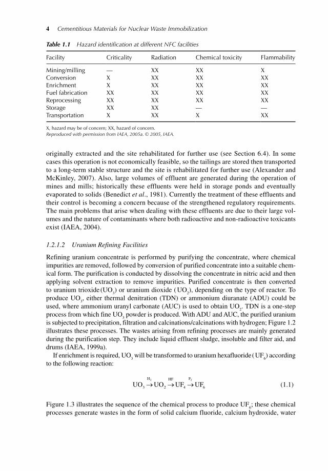