Efficiency of RC square columns repaired with polymer-modified cementitious mortars
Upload
khangminh22Category
view
1download
0
JOINT TRANSPORTATION RESEARCH PROGRAM INDIANA DEPARTMENT OF TRANSPORTATION AND PURDUE UNIVERSITY
Self-Healing Cementitious Composites (SHCC) with Ultrahigh Ductility for Pavement and Bridge Construction
Cihang Huang, Yen-Fang Su, Na (Luna) Lu
SPR-4326 • Report Number: FHWA/IN/JTRP-2021/36 • DOI: 10.5703/1288284317403

RECOMMENDED CITATIONHuang, C., Su, Y.-F., & Lu, N. (2021). Self-healing cementitious composites (SHCC) with ultrahigh ductility for pavement and bridge construction (Joint Transportation Research Program Publication No. FHWA/IN/JTRP-2021/36). West Lafayette, IN: Purdue University. https://doi.org/10.5703/1288284317403
AUTHORSCihang HuangGraduate Research AssistantLyles School of Civil EngineeringPurdue University
Yen-Fang SuGraduate Research AssistantLyles School of Civil EngineeringPurdue University
Na (Luna) Lu, PhDACPA ProfessorLyles School of Civil EngineeringPurdue University(765) [email protected] Author
JOINT TRANSPORTATION RESEARCH PROGRAMThe Joint Transportation Research Program serves as a vehicle for INDOT collaboration with higher education in-stitutions and industry in Indiana to facilitate innovation that results in continuous improvement in the planning, design, construction, operation, management and economic efficiency of the Indiana transportation infrastructure. https://engineering.purdue.edu/JTRP/index_html
Published reports of the Joint Transportation Research Program are available at http://docs.lib.purdue.edu/jtrp/.
NOTICEThe contents of this report reflect the views of the authors, who are responsible for the facts and the accuracy of the data presented herein. The contents do not necessarily reflect the official views and policies of the Indiana Depart-ment of Transportation or the Federal Highway Administration. The report does not constitute a standard, specifica-tion or regulation.

TECHNICAL REPORT DOCUMENTATION PAGE
1. Report No.FHWA/IN/JTRP-2021/36
2. Government Accession No. 3. Recipient’s Catalog No.
4. Title and SubtitleSelf-Healing Cementitious Composites (SHCC) with Ultrahigh Ductility forPavement and Bridge Construction
5. Report Date December 20216. Performing Organization Code
7. Author(s)Cihang Huang, Yen-Fang Su, and Na (Luna) Lu
8. Performing Organization Report No.FHWA/IN/JTRP-2021/36
9. Performing Organization Name and AddressJoint Transportation Research ProgramHall for Discovery and Learning Research (DLR), Suite 204207 S. Martin Jischke DriveWest Lafayette, IN 47907
10. Work Unit No.
11. Contract or Grant No.SPR-4326
12. Sponsoring Agency Name and AddressIndiana Department of Transportation (SPR)State Office Building100 North Senate AvenueIndianapolis, IN 46204
13. Type of Report and Period CoveredFinal Report14. Sponsoring Agency Code
15. Supplementary NotesConducted in cooperation with the U.S. Department of Transportation, Federal Highway Administration.16. Abstract
Cracks and their formations in concrete structures have been a common and long-lived problem, mainly due to the intrinsicbrittleness of the concrete. Concrete structures, such as rigid pavement and bridge decks, are prone to deformations and deteriorations caused by shrinkage, temperature fluctuation, and traffic load, which can affect their service life. Rehabilitation of concrete structures is expensive and challenging—not only from maintenance viewpoints but also because they cannot be used for services during maintenance. It is critical to significantly improve the ductility of concrete to overcome such issues and to enable better infrastructure quality. To this end, the self-healing cementitious composites (SHCC) investigated in this work could be a promising solution to the aforementioned problems.
In this project, the team has designed a series of cementitious composites to investigate their mechanical performances and self-healing abilities. Firstly, various types of fibers were investigated for improving ductility of the designed SHCC. To enhance the self-healing of SHCC, we proposed and examined that the combination of the internal curing method with SHCC mixture design can further improve self-healing performance. Three types of internal curing agents were used on the SHCC mixture design, and their self-healing efficiency was evaluated by multiple destructive and non-destructive tests. Results indicated a significant improvement in the self-healing capacity with the incorporation of internal curing agents such as zeolite and lightweight aggregate. To control the fiber distribution and workability of the SHCC, the mix design was further adjusted by controlling rheology using different types of viscosity modifiers. The team also explored the feasibility of the incorporation of colloidal nano-silica into the mix design of SHCC. Results suggest that optimum amounts of nano-silica have positive influence on self-healing efficiency and mechanical properties of the SHCC. Better hydration was also achieved by adding the nano-silica. The bonding strength of the SHCC with conventional concrete was also improved. At last, a standardized mixing procedure for the large scale SHCC was drafted and proposed. 17. Key Wordsself-healing, fiber reinforced cementitious composite, internalcuring, rheology, colloidal nano silica
18. Distribution StatementNo restrictions. This document is available through theNational Technical Information Service, Springfield, VA22161.
19. Security Classif. (of this report)Unclassified
20. Security Classif. (of this page)Unclassified
21. No. of Pages 62 including appendices
22. Price
Form DOT F 1700.7 (8-72) Reproduction of completed page authorized

EXECUTIVE SUMMARY
Introduction
The formation of cracks in concrete structures is commonly
observed due to the intrinsic brittleness of the concrete. Concrete
structures, such as rigid pavement and bridge decks, are prone to
deformation and deterioration caused by shrinkage, temperature
fluctuation, and traffic load, which can affect the service life of the
structure. The rehabilitation of the concrete structure can be
expensive and challenging since they are in continuous service.
Therefore, it is critical to develop self-healing cementitious
composites (SHCC) with ultra-high ductility to potentially over-
come the aforementioned issues.
In this project, the team designed a series of cementitious
composites to investigate their mechanical performance and self-
healing ability. First, various types of fibers were investigated to
improve the ductility of the designed SHCC. To enhance the self-
healing of SHCC, we tested if the combination of the internal
curing method with SHCC mixture would improve self-healing
performance. Three types of internal curing agents were used on
the SHCC mixture design, and the self-healing efficiency was
evaluated by using multiple non-destructive tests. The results
indicate a significant improvement in the self-healing capacity
with the incorporation of the internal curing agents. To control
the fiber distribution and workability of the SHCC, the mix design
was further adjusted by controlling the rheology using different
types of viscosity modifiers. The team also explored the feasibility
of the incorporation of nano-silica into the mix design of SHCC.
Better hydration was achieved by adding the nano-silica.
Moreover, the bonding strength between the SHCC and conven-
tional concrete layer was further improved. The results suggest
that a certain amount of nano-silica would positively influence
self-healing efficiency and the mechanical properties of the SHCC.
Finally, a standardized mixing procedure for the SHCC was also
developed.
Findings
We have conducted a comprehensive investigation of a series of
self-healing cementitious composites with various mix designs.
Extensive experiments were performed to investigate the effec-
tiveness of different variables, such as fibers properties, internal
curing agents, and various additives in SHCC. The findings of this
project are detailed as follows.
1. Findings related to different fibers.
N Mechanical and crack width control ability of six
different types of fibers, PVA (Polyvinyl Alcohol)
Fiber, Strux 90/40, Masterfiber Mac Matrix,
Fiberforce 650, Suf-Strand SF and Forta-Ferro One,
were evaluated with SHCC design. Experimental results
showed that SHCC samples with various fibers incor-
porated exhibited pseudo-strain-hardening behavior
during the loading process due to the bridging effect
of the fibers.
N Among the six mixtures tested, samples with PVA
(Polyvinyl Alcohol) fiber exhibited higher mechanical
strength performance. For compressive strength, the
PVA-SHCC performed 10% to 165% higher than
others; for tensile strength results, the PVA-SHCC
exceeded other sets by 24% to 65%; for flexural strength,
the PVA-SHCC behaved 5% to 101% higher than
SHCC incorporated with other fibers.
N Analysis of the flexural deflection shows that the crack
width control ability of the PVA fiber is stronger than
other fibers. PVA fiber can control the propagation of
the crack width by generating multiple narrowed cracks,
while fewer cracks were formed in the sample with
macro-fibers. It is also observed that PVA-SHCC
exhibited a lower flexural strain capacity compared with
others, which could be due to the shorter length of PVA
that makes it easier to be pulled out during the loading.
N Based on the experimental result, PVA fiber is the most
suitable fiber for the design of SHCC since it can lead
to higher mechanical strength and smaller crack width,
which is favorable for self-healing.
2. Findings related to internal curing aggregates.
N Two types of internal curing aggregates, Zeolite, and
lightweight aggregate were used and evaluated with
SHCC. Mechanical test results indicate that when
internal curing aggregates were used, the samples
showed over 15% compressive strength improvement
for the cementitious composites sample with zeolite and
a 6% improvement with lightweight aggregate.
N The use of the zeolite could increase the healing ratio
from around 2.0% to over 5.0% after the self-healing of
7 wet/dry cycles (28 days) based on two non-destructive
tests. Results of the experiment suggest that the optimal
zeolite replacing ratio for sand may be around 15 wt%.
The self-healing performance of SHCC incorporated
with lightweight aggregate was compared with the
zeolite. The results indicate that the lightweight aggre-
gate improved the healing efficiency of the SHCC, but
the improvement was not as significant as zeolite.
N Pore structure analysis suggests that the zeolite has a
finer pore size compared to lightweight aggregate
(LWA). During the self-healing period, zeolite is capable
of slowly but continuously supplying water to cementi-
tious materials. The continued water supply led to a
better autogenous self-healing performance.
N Experimental results provide solid evidence that the
internal curing aggregates can enhance healing efficiency
by providing water internally to accelerate the auto-
genous healing.
3. Findings related to superabsorbent polymer (SAP).
N Properties of the SAP were investigated and their
robustness evaluation shows that the SAP can be
influenced by the superplasticizer, hydration accelerator,
and fly ash. However, only a minor influence of less
than 10% was observed. Therefore, it can be concluded
that SAP is relatively robust under the designed
environmental conditions.
N During the experiments, a dramatic reduction in the
water flow rate from 0.2 g/s to 0.02 g/s was observed
within 60 seconds of the test when the SAP was
incorporated. Experimental results indicate that SAP is
an effective material for sealing the cracks in concrete
materials.
N Evaluation of the influence of the SAP on the rheology
of cement paste shows that as the dosage of the SAP
increased from 0% to 0.24 wt% of cement, the plastic
viscosity showed a dramatic improvement of over 56%.

This suggests that the incorporation of the SAP may be
able to improve interfacial friction between fiber and
matrix and further enhance the fiber distribution.
N Mechanical tests for the SHCC incorporated with SAP
indicate that incorporating the SAP particles reduced
the 7-days compressive and flexural strength of the
sample by over 25% and 20%, respectively, which was
due to the large voids left by the dried SAP particles.
It was also found that with a small dosage of the SAP,
the 7-days tensile performance of the SHCC was slightly
improved by around 13.8%. This may be due to the
improvement of fiber distribution and that the void
created by the SAP could act as flaws that triggered the
formation of multiple cracks. However, with a higher
dosage of SAP, the tensile strength was decreased again
because of the large quantity of voids.
4. Findings related to viscosity modifying admixtures (VMA).
N Three types of viscosity modifying agents were used, and
the properties of the SHCC were evaluated. The
viscosity results indicated that compared with thicken-
ing-type VMA, the binding-based VMA can better
increase the viscosity of fresh SHCC. The increase of the
viscosity of SHCC can prevent segregation, which
improves the interfacial properties between fiber and
matrix and fiber distribution.
N Mechanical tests results suggest that VMA 450 (binding
type) can effectively enhance the ductility of SHCC due
to the improvement of the fiber-matrix interface quality
and the fiber distribution.
5. Findings related to the nano-silica based SHCC.
N The team investigated the mechanical properties and
self-healing performance of SHCC incorporated with
colloidal nanosilica. The experimental result shows that
colloidal nanosilica can significantly improve mechan-
ical strength. For the compressive strength result, the
nanosilica-based SHCC can reach over 5,500 psi at
90 days. Flexural strength results indicate that SHCC
with nanosilica showed 7% to 9% higher flexural
strength than the reference set. Tensile results of
SHCC suggest that the nanosilica-based SHCC had a
higher tensile strength of over 500 psi.
N Self-healing evaluation suggests that the incorpora-
tion of nanosilica presents a positive impact on
autogenous healing of the SHCC. The result of the
resonant frequency test indicates that under the wet/dry
cycle condition, the RF recovery ratio of nanosilica-
based SHCC can recover 15% or above for 28 days.
After the designed self-healing period, the tensile testing
revealed that the SHCC sample with E5 colloidal nano
silica (CNS) can reach a higher tensile strength and
stiffness retention ratio than the reference SHCC
sample.
6. Large scale SHCC sample testing.
N To study the feasibility of utilizing designed material in
real field application, the team prepared the SHCC
mixture on a large scale. The workability assessment by
slump and J-ring tests indicates that the designed SHCC
with VMA possesses excellent workability and passing
ability which is comparable with self-consolidating
concrete (SCC).
N Layered structure beam was designed and tested to
further study the flexural performance of SHCC/
concrete composite. Different layer ratios between
SHCC and concrete were designed, and the result
suggests that as the ratio of the SHCC layer increased,
a higher modulus of rupture (MOR) could be achieved.
Specifically, the SHCC and concrete ratio of 3:1 can
achieve the optimal flexural performance.
N A standardized mixing procedure for the large scale
SHCC was developed based on the large batch mixing.
In the standardized procedure, it is suggested that extra
attention needs to be made to check the inner wall of the
mixer to ensure any agglomerate of the cementitious
materials could be mixed and dispersed by the mixer.
In addition, any additives that may counterweigh the
effect of the VMA should be added after the well-mix of
the PVA fibers.
Implementations
The objective of this project is to develop ductile self-healing
cementitious composites (SHCC), which can be used in concrete
applications especially for link-slab. The SHCC was delivered to
INDOT as a reference for the design of concrete materials with
ultra-high ductility and self-healing ability that can reduce the
need for conventional rehabilitation.
N To ensure the quality of the fiber distribution and the
ductility of the SHCC, PVA fiber with short fiber length,
high tensile strength, and aspect ratio was chosen. Better
mechanical properties and crack width control ability can
therefore be expected.
N The internal curing method was applied into the design of
the SHCC to further improve the self-healing performance.
Internal curing aggregates with high porosity and small pore
size, such as zeolite, performed better in the improvement of
the healing efficiency. Optimal sand replacing ratio for
zeolite is around 15 wt%.
N Superabsorbent polymer (SAP) can effectively seal the crack
within a short period; however, it has a negative influence on
the mechanical performance of the SHCC.
N Viscosity modifying admixtures (VMA) can effectively
improve the fiber distribution and fiber-matrix interface
of the SHCC, especially when a higher water to cement
ratio is used. The experimental result indicates VMA 450
(binding type) with a dosage of 1% performed the best in
SHCC with a water to cement ratio of 0.35, in terms of
ductility.
N Addition of the colloidal nanosilica can further improve
the mechanical and self-healing performance of the SHCC.
The test result suggests 0.6 wt% of cement as the optimal
dosage. Also, the bonding strength between the SHCC and
conventional concrete layer was increased with the addition
of the nanosilica.
N SHCC mixture design with VMA has been proved to possess
satisfied workability and passing ability, which is compar-
able with self-consolidating concrete (SCC).
N The combination of the SHCC with conventional concrete
can improve the flexural performance of the beam sample.
A higher flexural strength with high modulus of rupture
(MOR) can be achieved.
N Different strategies for the design of the SHCC can be
adopted based on certain applications. For a concrete
patching project, it is more desirable to have SHCC with a
better curing quality and higher bonding strength. Therefore,

it is recommended to incorporate the internal curing agent
and colloidal nanosilica, which are proven to lead to better
curing and bonding performance. A lower PVA fiber content
of 1 vol% may be used to reduce the cost. On the other hand,
if SHCC is used for a link slab application, ductility and the
self-healing ability are favorable. Thus, a higher dosage of
the PVA fiber, such as 2 vol% can be used. Internal curing
agents such as zeolite can be incorporated to further improve
the self-healing performance.
Limitations and Future Studies
The extensive experiments conducted in this project have laid
the foundation for the design of ultra-high ductility self-healing
cementitious composites (SHCC). This project proved the
effectiveness of using internal curing agents to improve the
self-healing performance of the designed cementitious composite.
The properties of the SHCC can be adjusted by selecting different
types of fibers, internal curing agents, and VMA based on specific
requirements. Nevertheless, there are still several limitations as
discussed below.
N Although the properties of the designed SHCC have been
systematically evaluated in the laboratory and in the
relatively large batch, the performance of the specimen
prepared by in-field batch mixing equipment still needs to be
verified.
N For the long-term durability, limited research has been done
for the SHCC, such as freeze-thaw, chloride penetration,
corrosion resistance, and alkali–silica reaction (ASR) resis-
tance.

CONTENTS
1. INTRODUCTION . . . . . . . . . . . . . . . . . . . . . . . . . . . . . . . . . . . . . . . . . . . . . . . . . . . . . . . . . . . . . . 11.1 Background . . . . . . . . . . . . . . . . . . . . . . . . . . . . . . . . . . . . . . . . . . . . . . . . . . . . . . . . . . . . . . . . . 11.2 Objective . . . . . . . . . . . . . . . . . . . . . . . . . . . . . . . . . . . . . . . . . . . . . . . . . . . . . . . . . . . . . . . . . . . 11.3 Organization of the Report . . . . . . . . . . . . . . . . . . . . . . . . . . . . . . . . . . . . . . . . . . . . . . . . . . . . . . 1
2. LITERATURE REVIEW . . . . . . . . . . . . . . . . . . . . . . . . . . . . . . . . . . . . . . . . . . . . . . . . . . . . . . . . . 12.1 Self-Healing of Concrete . . . . . . . . . . . . . . . . . . . . . . . . . . . . . . . . . . . . . . . . . . . . . . . . . . . . . . . . 12.2 Fiber-Reinforced Concrete . . . . . . . . . . . . . . . . . . . . . . . . . . . . . . . . . . . . . . . . . . . . . . . . . . . . . . 22.3 Internal Curing for Concrete Material . . . . . . . . . . . . . . . . . . . . . . . . . . . . . . . . . . . . . . . . . . . . . . 32.4 Summary. . . . . . . . . . . . . . . . . . . . . . . . . . . . . . . . . . . . . . . . . . . . . . . . . . . . . . . . . . . . . . . . . . . 5
3. EFFECT OF DIFFERENT CONFIGURATIONS OF FIBERS . . . . . . . . . . . . . . . . . . . . . . . . . . . . . 53.1 Objective . . . . . . . . . . . . . . . . . . . . . . . . . . . . . . . . . . . . . . . . . . . . . . . . . . . . . . . . . . . . . . . . . . . 53.2 Experimental Method . . . . . . . . . . . . . . . . . . . . . . . . . . . . . . . . . . . . . . . . . . . . . . . . . . . . . . . . . . 53.3 Result and Discussion. . . . . . . . . . . . . . . . . . . . . . . . . . . . . . . . . . . . . . . . . . . . . . . . . . . . . . . . . . 63.4 Summary. . . . . . . . . . . . . . . . . . . . . . . . . . . . . . . . . . . . . . . . . . . . . . . . . . . . . . . . . . . . . . . . . . . 8
4. INTERNAL CURING AGENT-BASED SHCC. . . . . . . . . . . . . . . . . . . . . . . . . . . . . . . . . . . . . . . . . 94.1 Objective . . . . . . . . . . . . . . . . . . . . . . . . . . . . . . . . . . . . . . . . . . . . . . . . . . . . . . . . . . . . . . . . . . . 94.2 Experimental Method . . . . . . . . . . . . . . . . . . . . . . . . . . . . . . . . . . . . . . . . . . . . . . . . . . . . . . . . . . 94.3 Effect of Using Zeolite in SHCC . . . . . . . . . . . . . . . . . . . . . . . . . . . . . . . . . . . . . . . . . . . . . . . . . . 94.4 Effect of Using Lightweight Aggregates in SHCC . . . . . . . . . . . . . . . . . . . . . . . . . . . . . . . . . . . . . 124.5 Effect of Using Superabsorbent in SHCC . . . . . . . . . . . . . . . . . . . . . . . . . . . . . . . . . . . . . . . . . . . 174.6 Summary. . . . . . . . . . . . . . . . . . . . . . . . . . . . . . . . . . . . . . . . . . . . . . . . . . . . . . . . . . . . . . . . . . 20
5. RHEOLOGY CONTROL OF SHCC. . . . . . . . . . . . . . . . . . . . . . . . . . . . . . . . . . . . . . . . . . . . . . . . 205.1 Introduction . . . . . . . . . . . . . . . . . . . . . . . . . . . . . . . . . . . . . . . . . . . . . . . . . . . . . . . . . . . . . . . 205.2 Effect of SAP on the Rheology of SHCC . . . . . . . . . . . . . . . . . . . . . . . . . . . . . . . . . . . . . . . . . . . 205.3 Effect of VMA on Rheological Control of SHCC . . . . . . . . . . . . . . . . . . . . . . . . . . . . . . . . . . . . . 245.4 Summary. . . . . . . . . . . . . . . . . . . . . . . . . . . . . . . . . . . . . . . . . . . . . . . . . . . . . . . . . . . . . . . . . . 25
6. NANOSILICA BASED SHCC . . . . . . . . . . . . . . . . . . . . . . . . . . . . . . . . . . . . . . . . . . . . . . . . . . . . 276.1 Introduction . . . . . . . . . . . . . . . . . . . . . . . . . . . . . . . . . . . . . . . . . . . . . . . . . . . . . . . . . . . . . . . 276.2 Mixture Design and Experiment Procedure. . . . . . . . . . . . . . . . . . . . . . . . . . . . . . . . . . . . . . . . . . 276.3 Results and Discussion . . . . . . . . . . . . . . . . . . . . . . . . . . . . . . . . . . . . . . . . . . . . . . . . . . . . . . . . 286.4 Summary. . . . . . . . . . . . . . . . . . . . . . . . . . . . . . . . . . . . . . . . . . . . . . . . . . . . . . . . . . . . . . . . . . 34
7. LARGE SCALE SHCC SAMPLE TESTING AND THE MIXING PROCEDURE . . . . . . . . . . . . . . 347.1 A Standardized Procedure for Large Batch SHCC Mixing . . . . . . . . . . . . . . . . . . . . . . . . . . . . . . . 347.2 Workability and Passing Ability . . . . . . . . . . . . . . . . . . . . . . . . . . . . . . . . . . . . . . . . . . . . . . . . . 357.3 Layer Structure Design for SHCC-Concrete . . . . . . . . . . . . . . . . . . . . . . . . . . . . . . . . . . . . . . . . . 357.4 Summary. . . . . . . . . . . . . . . . . . . . . . . . . . . . . . . . . . . . . . . . . . . . . . . . . . . . . . . . . . . . . . . . . . 36
8. ADVANTAGE OF SHCC DESIGN FOR IN-FIELD APPLICATIONS . . . . . . . . . . . . . . . . . . . . . . 368.1 Economic Competitiveness . . . . . . . . . . . . . . . . . . . . . . . . . . . . . . . . . . . . . . . . . . . . . . . . . . . . . 368.2 Expected Benefits . . . . . . . . . . . . . . . . . . . . . . . . . . . . . . . . . . . . . . . . . . . . . . . . . . . . . . . . . . . . 368.3 Implementation . . . . . . . . . . . . . . . . . . . . . . . . . . . . . . . . . . . . . . . . . . . . . . . . . . . . . . . . . . . . . 37
9. FINAL CONCLUSIONS AND RECOMMENDATIONS. . . . . . . . . . . . . . . . . . . . . . . . . . . . . . . . . 38
REFERENCES . . . . . . . . . . . . . . . . . . . . . . . . . . . . . . . . . . . . . . . . . . . . . . . . . . . . . . . . . . . . . . . . . 39
APPENDIX . . . . . . . . . . . . . . . . . . . . . . . . . . . . . . . . . . . . . . . . . . . . . . . . . . . . . . . . . . . . . . . . . . . . 43

LIST OF FIGURES
Figure Page
Figure 3.1 Dog-bone specimen for uniaxial tensile loading 6
Figure 3.2 Compressive strength results of SHCC incorporated with various fibers 7
Figure 3.3 Tensile strength results of SHCC incorporated with various fibers 7
Figure 3.4 Flexural strength results of SHCC incorporated with various fibers 8
Figure 3.5 Stress-strain curve of SHCC with various fibers 8
Figure 4.1 Compressive strength of different samples 10
Figure 4.2 Splitting tensile strength of different samples 10
Figure 4.3 Self-healing performance at different Zeolite replacing ratios: (a) resonant frequency test and
(b) ultrasonic pulse velocity test 11
Figure 4.4 Schematic of blocking effect 12
Figure 4.5 The tensile strength retention ratio of different SHCC sample after 7 cycles 12
Figure 4.6 Experimental procedure for autogenous healing evaluation 13
Figure 4.7 Result of 28 days compressive test 13
Figure 4.8 Result of 28 days flexural test 14
Figure 4.9 Result of 28 days uniaxial tensile test 14
Figure 4.10 Recovery ratio of designed materials based on resonant frequency measurement 14
Figure 4.11 Healing of cracks throughout wet/dry cycles (from mixture R-0) 15
Figure 4.12 Water desorption behavior of internal curing agents 16
Figure 4.13 SEM images of internal curing agents: (a–b) lightweight aggregate and (c–d) Zeolite 16
Figure 4.14 Bulk sample water absorption capacity 17
Figure 4.15 Evaluation of the SAP robustness under various superplasticizer dosage: (a) filtration test and (b) void size analysis 18
Figure 4.16 Evaluation of the SAP robustness under various hydration accelerator dosage: (a) filtration test and
(b) void size analysis 19
Figure 4.17 Evaluation of the SAP robustness under various fly ash content 19
Figure 4.18 Water flow rate of the testing samples 19
Figure 4.19 Weight of the cumulative passing water 20
Figure 5.1 Flow curve of SAP cement (left), the effect of SAP on the plastic viscosity and dynamic yield stress
of cement paste (right) 21
Figure 5.2 Viscosity evaluation of the SHCC based SAP 22
Figure 5.3 Mini-slump test for SHCC with 0.664% SAP 22
Figure 5.4 Compressive strength result for the SHCC-SAP 23
Figure 5.5 Flexural strength result for the SHCC-SAP 23
Figure 5.6 Tensile strength result for the SHCC-SAP 24
Figure 5.7 Experimental logistic of VMA-SHCC 25
Figure 5.8 Results of viscosity measurements with various configuration of VMA 25
Figure 5.9 Comparison of the viscosity of three types of VMA (1%)
Figure 5.10 Results of mini-slump test with various configuration of VMA-SHCC with PVA fiber 26
Figure 5.11 Results of mini-slump test with various configuration of VMA-SHCC with Strux fiber 27
Figure 6.1 Experiment procedure of self-healing evaluation with nanosilica 28
Figure 6.2 Compressive strength results 29
26

Figure 6.3 Four-points flexural test results 29
Figure 6.4 Ductility index 29
Figure 6.5 Tensile strength results 30
Figure 6.6 Dry shrinkage results of SHCC-E5 30
Figure 6.7 Bond strength results of SHCC-E5 30
Figure 6.8 Results of resonant frequency test (SHCC exposed to W/D cycle) 31
Figure 6.9 Results of resonant frequency test (SHCC exposed to 50% RH dry condition) 31
Figure 6.10 Results of tensile strength and stiffness retention ratio test (SHCC exposed to W/D cycles) 32
Figure 6.11 Results of tensile strength and stiffness retention ratio test (SHCC exposed to dry conditions) 32
Figure 6.12 Representative microscope images for sample (0.3% E5 SHCC) after preloaded and two W/C cycles 33
Figure 6.13 Results of average crack recovery ratio for SHCC under W/D cycle curing condition 33
Figure 6.14 Probability of SHCC crack width after three-points bending test 33
Figure 6.15 Average area of unhydrated cementitious materials of different SHCC samples 34
Figure 7.1 Set up and results of SHCC J-ring testing 35
Figure 7.2 Schematic of SHCC/concrete beam 36
Figure 7.3 The MOR result of SHCC/concrete structure 36
Figure 8.1 Estimated material cost per cubic yard 37

LIST OF TABLES
Table Page
Table 3.1 Mixture design (by weight of cement) 6
Table 4.1 Compositions of concrete mixtures (proportions expressed as fraction of cement weight) 9
Table 4.2 Mixture design (by weight of cement) for the study of internal curing aggregates 13
Table 4.3 Crack width reduction ratio of different mixtures 15
Table 5.1 Mixture composition for the evaluation of slump and viscosity of SAP-SHCC 22
Table 5.2 Result of the mini-slump test 22
Table 5.3 Mixture design for the evaluation of the mechanical properties of SHCC-SAP 23
Table 5.4 Experiment dosages of different VMA 24
Table 6.1 Composition of SHCC with nanosilica (by cement weight) 28
Table 7.1 Workability results of SHCC compared with SCC criteria 35
Table 8.1 Estimated material cost of different mixture designs 37

1. INTRODUCTION
1.1 Background
Cracks always occur in conventional concrete infra-structures such as bridge construction, particularly thelink-slab application due to structural deflection, con-crete shrinkage, and temperature variation. Signif-icantly, combined with the freeze-thaw condition andthe use of deicing salt in northern regions, the damageof concrete structures caused by cracks is furtheramplified. The existence of the cracks in concreteshortens the service life of the structure by generating apathway for harmful compounds to invade concretefrom the external environment. Additionally, concreteinfrastructures, such as bridges and highway pavement,are always in continuous service, making the repair orreplacement even harder. To address this problem, it isnecessary to design ductile concrete with the ability toself-heal the cracks. The ductility could prevent theconcrete materials from sudden failure; simultaneously,the self-healing ability could prevent the event of crackspropagation and elongate the service life of the concretematerials.
The presence of water is one of the most criticalfactors governing the efficiency of autogenous healingin concrete. The concept of incorporation of theinternal water reservoir in concrete materials has beenwell developed for internal curing and shrinkagemigration. The internal curing method has been widelyused to supply water internally to eliminate early ageshrinkage. Thus, the combination of internal curingand autogenous healing has the potential to enhanceautogenous healing performance.
This study proposes to develop fiber-reinforced self-healing cementitious composites (SHCC) with ductilitythat can be used in bridge applications such as link-slab. The designed material has the necessary self-healing ability to heal the cracks within one season toeliminate the potential issues of reinforcement corro-sion and crack propagation.
1.2 Objective
This program aims to develop ductile self-healingcementitious composites (SHCC), which enables thehealing of formed cracks within one season cycle toeliminate the potential deterioration of concrete infra-structure. The self-healing performance of the concreteis evaluated with the incorporation of three differenttypes of internal curing agents with various mix designs,including lightweight aggregate, zeolite, and super-absorbent polymer (SAP). A hypothesis is proposedthat the incorporation of the internal curing agents canimprove the self-healing behavior of the designedconcrete and evaluated in this project. Various typesof fibers are examined to optimize the mechanicalproperties of the material. The rheological properties ofthe SHCC are adjusted, and the nano-silica is used toimprove the properties of the designed material. Assuch, this project provides a recommendation for the
design guidelines of the cementitious composite withself-healing ability and excellent mechanical perfor-mance, which can be used in concrete application,especially for link-slab.
1.3 Organization of the Report
This report consists of seven chapters. This firstchapter introduces the background and objective of thisresearch. The second chapter reviews previous researchfor the design of high-performance concrete, includingthe design of self-healing cementitious composite,properties of fiber reinforced concrete, internal curingmethod, and the rheology control of the concretematerials. The third chapter evaluates and comparesvarious types of fibers that can potentially use inSHCC. The fourth chapter reports the self-healingperformance of the SHCC with the incorporation of theinternal curing agents. The fifth chapter presents therheology adjustment of the SHCC by different meth-ods. The sixth chapter reports the further improvementof the SHCC by using nano-silica. The seventh chapterincludes the large batch mixing and testing of theSHCC, and a standardized mixing procedure is pro-vided. The last part of this report presents a conclusionand recommendation for the design of the SHCC.
2. LITERATURE REVIEW
Concrete is widely used in construction projects.Concrete structures can be designed to have a servicelife as long as several decades. However, cracking inconcrete can lead to the deterioration of the structure.The formation of cracks can be attributed to a varietyof reasons. Timely repairs and rehabilitation which canprevent further deterioration are necessary for theconcrete structure. However, those works could beextremely expensive, not to mention infrastructuressuch as bridges, tunnels, and pavement require con-tinuous service that can further increase the difficulty ofthe repair or rehabilitation.
To address the above-mentioned issues, concretewith the ability to self-heal the crack has been proposedand studied. The idea for self-healing concrete is thatafter the formation of cracks, concrete itself can re-generate solid substances that can block the cracks andeven recover its mechanical strength.
2.1 Self-Healing of Concrete
Autogenous healing of the concrete is associated withthe physical or chemical processes that occur in thecementitious matrix, as shown in Figure A.1 (Yang etal., 2009). By analyzing the healing product in the crackmouth, newly formed C-S-H gel (Jacobsen et al., 1995)and calcium carbonate were found (Edvardsen, 1999),which implies that the main mechanisms of the auto-genous healing are the secondary hydration, carbona-tion of calcium hydroxide and the crystallization ofportlandite (Ca(OH)2) (Huang et al., 2016; Keskin
Joint Transportation Research Program Technical Report FHWA/IN/JTRP-2021/36 1

et al., 2016). Solid healing products can block thecracks and prevent the entrance of aggressive agents.As a result, the further deterioration of the concrete canbe prevented, which ensures the service life of thestructure (Yang et al., 2009). Among different auto-genous healing mechanisms, secondary hydration hasbeen proved to be highly responsible for the recoveryof the mechanical properties of the concrete structure.The newly formed healing products from secondaryhydration possess a strength property that is able tore-connect the crack face and concrete debris together(Snoeck, 2015).
One of the most important factors that can affect theefficiency of the self-healing is the selection ofcementitious materials. Previous research indicates thatpartially replacing cement with fly ash and/or blastfurnace slag can significantly improve the healingperformance of the concrete (Termkhajornkit et al.,2009; Yang et al., 2009). The underlying mechanism isthat compared with cement clinker, fly ash and slagpossess a lower reactivity, leading to a decrease in theearly age hydration rate. Therefore, a larger amount ofunreacted cementitious materials can be reserve forsecondary hydration. It is also worth noting that thepozzolanic reaction of the fly ash and slag requires theexistence of the calcium hydroxide. And it is knownthat calcium hydroxide is one of the hydration productsof the cement. Thus, the replacement of the cement bythe fly ash or slag should be controlled and limited toensure that a sufficient amount of the cement will behydrated to produce calcium hydroxide which can beused for secondary hydration of the fly ash or slag(Zhang et al., 2014).
Different exposure conditions have been studied byvarious researchers (Hung et al., 2017; Roig-Floreset al., 2016; Sisomphon, 2013). Hung et al. (2017)evaluated the healing performance of cementitiouscomposites under three different curing conditions:lab-controlled dry, water submersion and naturalweathering with high humidity. The result shows thatthe samples cured in a lab-controlled environmentexhibited limited healing performance, compared withthe other two curing environments with water supply(Hung et al., 2018). A similar conclusion was also foundin other research (Jiang et al., 2015; Ma et al., 2014).Thus, it can be seen that in order to achieve sufficientautogenous healing in cementitious material, watersupply is of vital importance. During the autogenoushealing process, water can act as a carrier for the fineparticles and ions, and it is also indispensable for thechemical reactions. Previous research found out thatthe healing efficiency in wet/dry cycles is higher thanthat in complete water submersion. This may be due tothe wet curing can provide water for secondaryhydration, while the CO2 is available for the precipita-tion of calcium carbonate during dry conditions.Therefore, the combination of secondary hydrationand the carbonation during the wet/dry cycles can leadto a higher autogenous healing efficiency (Ma et al.,2014).
In addition to the mixture design and curingcondition, the crack width is another factor that cansignificantly influence the healing efficiency. The widthof the crack can directly determine the amount ofhealing products that are required to plug the crack(Gagne & Argouges, 2012). The internal tensile stresscaused by the shrinkage, external loading, or thermalexpansion may lead to the intensive propagation of thecrack width. If the crack width can be controlled duringthe loading process, the autogenous healing perfor-mance can be improved. Therefore, fibers have beenintroduced to the development of self-healing concrete(Yang et al., 2009). The fiber can act as bridges insidethe concrete material and limit the propagation ofthe crack mouth. In addition to the crack width control,the reinforced fiber can also act as nucleation sitesfor the secondary hydration and the carbonationof calcium hydroxide. According to the microscopicobservation, the healing products were found on thebridging fiber across the crack (Homma et al., 2009).
Based on the mechanisms of the autogenous healing,it is an intrinsic ability of cementitious material; withproper design, the concrete material can possess self-healing ability without aggressively increasing the costand construction difficulty (Van Tittelboom & DeBelie, 2013).
2.2 Fiber-Reinforced Concrete
Concrete is a complex composite material composedof fine and coarse aggregate bonded with cementmortar. The border between different particles, espe-cially the mortar-aggregate interface, is typically theweak spot of the concrete material (Akcaoglu et al.,2004). The crack may therefore tend to generate at theweak spot during the service life of the concrete.Without timely repair, those cracks may propagate andcause further deterioration of the concrete structure.It can be expected that a crack with a larger widthrequires a larger amount of solid products in orderto reach completed sealing (Yıldırım et al., 2015).Therefore, the control of crack width has the potentialto further improve the efficiency of autogenous healing(Mihashi & Nishiwaki, 2012). To address this issue,researchers have used fiber as reinforcement to controlthe crack width in concrete material (Nishiwaki et al.,2012; Qian et al., 2010). Generally, the tensile strengthof the fiber used in the concrete industry is much higherthan that of the hardened concrete matrix. The fibercan improve the post-cracking behavior of the concretematerial by transferring the stress between crack facesand controlling the increase of the crack width(Bischoff, 2003; Paipetis et al., 1999). In addition,previous studies indicated that fiber can be used toproduce concrete material with increased toughness anddurability performance (Kuder & Shah, 2010; Lau &Anson, 2006).
In fiber-reinforced concrete, upon the formation ofthe crack, embedded fibers with random distributioncan act as bridges to limit the propagation of the crack
2 Joint Transportation Research Program Technical Report FHWA/IN/JTRP-2021/36

and transfer the stress across the mouth of the crack(Cattaneo & Biolzi, 2010; Kaufmann et al., 2019).As a consequence, the strength and durability of theconcrete with the incorporation of fiber as rein-forcement are generally higher than the plain concrete(Ding & Kusterle, 2000). Nowadays, various fibertypes, such as steel fiber, glass fiber, carbon fiber, andPVA fiber, etc., have been developed and used in theconcrete industry. Different parameters of the fiber,such as length and aspect ratio, can significantly affectthe performance of the fiber-reinforced concrete(Afroughsabet et al., 2016).
The fiber geometry can intensively influence theconcrete properties. In the Doo-Yeol Yoo et al., (2015)study, the increase of the fiber length effectivelyenhanced the flexural deflection capacity of thecementitious composite (Yoo et al., 2015). In fiber-reinforced concrete, the completed pull out of the fiberscan be considered as the main reason for the concretefailure. And the pull-out effect of the fiber can bedetermined by the bonding condition between the fiberand matrix. It can be expected that a longer fibergenerally leads to an increase in the bonding areabetween fiber and the matrix, which results in animprovement in the ductility of the concrete (Yoo et al.,2015). Therefore, tailoring the fiber length can poten-tially affect the mechanical performance of the con-crete. In addition, the researchers noticed that theincrease in the fiber length could potentially lead tofiber entanglement and poor distribution, which maylead to a more porous structure (Yoo et al., 2014).It was reported that concrete material with longerfiber exhibited a lower compressive strength comparedwith those with shorter fiber (Chen & Carson, 1971).A similar experimental result was also found inNoushini et al’s study, where the increase of the lengthof the PVA fiber enhanced the strain capacity of thesample while the improvement in splitting tensilestrength of the concrete was not observed (Noushiniet al., 2013). Based on previous work, it can beconcluded that the length of the fiber can effectivelyinfluence the mechanical performance of the designedconcrete. However, a balance exists between thepositive and negative effects of using longer or shorterfibers. Apart from the fiber length, previous studiesshowed that the aspect ratio of the fiber is anotherprimary factor that can affect the mechanical propertiesof the concrete. It was reported that the increase in theaspect ratio could lead to higher compressive strengthand toughness (Eren & Celik, 1997). In Hameed et al.’sstudy, it was proposed that a larger aspect ratio ofthe fiber could result in a better control of the crackpropagation. Therefore, the increment of the compres-sive and flexural strength can be expected when fiberwith a higher aspect ratio is used (Hameed et al., 2009).
According to the literature review, it can be seen thatthe parameters of the fiber may affect the properties ofthe concrete material in a different way. Therefore,during the mixture design of the fiber-reinforced
cementitious material, the selection of the fiber needsto depend on the specific requirement or application.
2.3 Internal Curing for Concrete Material
To design high-performance concrete, people gen-erally increase the content of the cementitious materialto produce a denser and stronger cementitious matrix.However, even though the low water to cement ratiobenefits the strength of the concrete, it also increasesthe risk of the early age shrinkage cracks formation(Cusson & Hoogeveen, 2007). During the hydrationprocess, the loss of water and relative humidity decreaseleads to self-desiccation that generates internal stress.Under the constraint condition, the internal stress cancause the formation of cracks, which may lead to theearly age failure of the concrete. For concrete withrelatively high water to cement ratio, the external cur-ing method can supply moisture and mitigate shrink-age. However, when it comes to the concrete with lowwater to cement ratio, a low permeability caused by thedense matrix does not allow the transfer of externalwater from the surface to the interior of the material(Bentz & Snyder, 1999). Therefore, external curing haslimited efficiency in shrinkage reduction for theconcrete with high binder content (Bentz et al., 2005).
In order to mitigate the potential damage caused byshrinkage in concrete with low water to cement ratio,the internal curing method has been developed; theschematic is shown in Figure A.2 (de la Varga et al.,2012). Pre-wetted internal curing agents with highwater absorption capacity are used to serve as waterreservoirs to supply extra water from the inside of theconcrete material (Ma et al., 2019). It has been provedthat the pre-wetted internal curing agent can releasesthe water once held in its structure during the hydrationand prevent the autogenous shrinkage of high-perfor-mance concrete (Bentur et al., 2001).
2.3.1 Internal Curing Aggregates
In the application of the internal curing method,selection of the internal curing agent is of vitalimportance. The internal curing agent can not onlyaffect the shrinkage reduction efficiency but also themechanical properties of the concrete. Pre-wettedporous aggregates were initially used to partiallyreplace the sand in high-performance concrete to serveas the internal curing agent. The porosity of the internalcuring aggregates is generally responsible for theabsorption capacity. High absorption capacity canpotentially increase the effectiveness of the internalcuring by carrying a larger amount of extra water. Inaddition, the size distribution of the pores inside theinternal curing aggregate also influences the internalcuring efficiency (Henkensiefken et al., 2009a; Ma et al.,2019). The previous study indicated that the pores ininternal curing aggregate need to be larger than those inthe cementitious matrix so that the water carried by the
Joint Transportation Research Program Technical Report FHWA/IN/JTRP-2021/36 3

aggregate will be preferentially released and consumedby the hydration process (Bentz et al., 2001).
Various types of internal curing aggregates have beenstudied and used in high-performance concrete materi-als (Dixit et al., 2019; Masum & Manzur, 2019; Tuet al., 2018). Among them, expanded lightweightaggregate is one of the most frequently used internalcuring agents. It has been proved that completeelimination of the shrinkage may be expected when25% of the normal-weight aggregate is replaced bylightweight aggregate (Bentur et al., 2001). The largepore with a diameter of greater than 1 mm in lightweightaggregate can be saturated within a short time andexhibit low water retention ability (Ma et al., 2019).During the early age hydration process, those largepores are capable of releasing most of their absorbedwater at high relative humidity. Thus, it is an effectiveinternal curing agent to reduce early age shrinkage byproviding water to replenish the empty pores caused byself-desiccation (Castro et al., 2011). On the other hand,clinoptilolite zeolite, a porous aluminosilicate mineral,was reported to have nm-sized pores capable of storingwater down to low relative humidity levels (Ghourchianet al., 2013; Zhang et al., 2018). The previous studyindicated that the incorporation of pre-wetted zeolitecould result in a shrinkage reduction of over 30%
(Zhang et al., 2017). In Ghourchian et al.’s study, theinternal curing efficiency of the zeolite is compared withexpanded lightweight aggregate. It is reported that the24 hours absorption capacity of the zeolite is around41.8% higher than the lightweight aggregate. Themercury intrusion porosimetry test evaluated the sizedistribution of the pores. The result showed thatlightweight aggregate possessed a coarse pore structure,while a large volume fraction of the nano-pore existedin the zeolite. For the absorption/desorption behavior,the lightweight aggregate was capable of releasing morethan 95% of its absorbed water at a relative humidity of90%, while zeolite retained around 90% of the waterunder the same environmental condition. Therefore, itis more likely for the zeolite to store part of its absorbedwater instead of releasing it for early age hydration.Consequently, due to the high water retention capacityof the zeolite, lesser reduction of shrinkage could beexpected when the zeolite is used as an internal curingagent (Ghourchian et al., 2013).
For the mechanical properties of the concreteincorporated with internal curing aggregate, a balanceexists between the side effect of the porous structure ofthe internal curing aggregate and the positive effect ofthe internal curing. The high porosity of the internalcuring aggregate may negatively affect the strength ofthe concrete, while a higher degree of hydration causedby the extra water carried by the curing agent has apositive effect on the mechanical properties of theconcrete (Bentz & Weiss, 2011). In previous studies,both decrease and increase in strength caused byinternal curing have been observed. It was reportedthat the use of the internal curing method resulted in adecrease of the early age compressive and tensile
strength of the concrete, mostly due to the porousstructure and larger particle size of the lightweightaggregate (Sahmaran et al., 2009). On the contrary,an increase in the long-term compressive strengthwas observed in Bentz’s study. It was concluded thatin the designed high-performance blended cementmortar, the improvement in the hydration overcamethe negative influence of the porous structure of theinternal curing agent, which resulted in an increase ofthe concrete strength (Bentz, 2007). Similar result wasalso found in other studies (de la Varga et al., 2012;Van et al., 2014).
2.3.2 Superabsorbent Polymer (SAP)
After the invention of the internal curing method,some concerns have been reported about the use ofporous aggregates, requiring the pre-soaking prior tomixing. This could be difficult to handle in the fieldapplications due to the lack of reasonable controlover the absorption capacity of the curing aggregate.Also, the incorporation of the porous aggregate willlead to the decrement of the mechanical propertiesdue to the incorporation of porous components(Jensen & Hansen, 2001). Therefore, superabsorbentpolymers (SAP), which can be added in the cementmixtures in the form of dry powders, were proposedas a new type of internal curing agent to prevent theshrinkage of concrete and has been widely studied(Mechtcherine et al., 2006; 2014). SAPs are a groupof cross-linked polymers with the ultra-high waterabsorption capacity of hundreds of times of theirown weight (Kong et al., 2015). SAPs are able toabsorb water and expand to form an insoluble gelthat acts as a barrier to the flow of the water.Afterward, SAPs can release the absorbed waterwithin the concrete and prevent shrinkage when thesurrounding humidity drops. The water absorptionmechanism of SAP is mainly the osmotic pressurearising from the difference in the concentration ofions between the gel and the surrounding solution(Lee et al., 2018). In the application of internal cur-ing, crosslinked poly-acrylic/acid-acrylamide mole-cule is the most commonly used type of SAP (Zhuet al., 2015). In Jensen and Hansen’s study, a high-performance cementitious composite blended withsilica fume was designed with a water to cement ratioof 0.3 (Jensen & Hansen, 2002). In this referencesample without the addition of SAP, shrinkagedeformation was observed up to 3,700 mm/m at theage of 21 days. However, when SAP was added at arate of 0.3 and 0.6 wt% of binder, it was observedthat the internal relative humidity of the concretewas effectively increased during the early age of thehydration process. The test result indicated that a0.6 wt% of SAP addition could fully eliminate theshrinkage (Jensen & Hansen, 2002). Similar resultwas also found in other studies, which proved thatSAP could be used as an effective internal curingagent (Just et al., 2015; Mechtcherine et al., 2006).
4 Joint Transportation Research Program Technical Report FHWA/IN/JTRP-2021/36

In Hasholt et al’s (2012) paper, it was reported thatthe overestimate of SAP water absorption capacitycould result in an incorrect mixture design, where theextra water added for internal curing is too large. As aconsequence, the increase of the actual water to cementratio may result in a decrease in the concrete strength(Hasholt, 2012). In Lee et al’s (2018) study, it wasobserved that the concentration of the cations and thealkalinity of the environment could intensively influ-ence the swelling behavior of the SAP. The study foundout that the calcium ions are capable of binding withcarboxylate groups in the acrylate chains of the SAP,which further decreases the absorption capacity of theSAP (Lee et al., 2018). Similarly, Zhu et al. (2015)reported that a stiff shell structure was formed when theSAP sample was immersed in the Al3+ solution. Thepresence of the barrier layer directly reduces the waterabsorption capacity of the SAP by hindering the watertransportation between the SAP and the solution (Zhuet al., 2015). Therefore, it can be concluded that thebehavior of the SAP can be affected by environmentalconditions. It is necessary to understand the robustnessof the SAP to optimize the mixture design when SAP isused as an internal curing agent.
2.4 Summary
According to the literature review, the healing ofcracks with smaller width requires less amount of solidproduct, which is more likely to be completed healed.Therefore, the efficiency of the autogenous healingperformance could be improved by incorporating fibersto control the crack width propagation. On the otherhand, according to the mechanisms of autogenoushealing, it can be noticed that water is a critical factorfor the autogenous healing of concrete materials.A sufficient self-healing phenomenon can only beobserved when external water is available. However,the external water supply is not continuous andunstable. Thus, developing a method that can avoidthe limitation of the external water supply will bebeneficial to the autogenous healing efficiency. Internalcuring is a well-developed method that suppliesadditional water for cementitious material to eliminateearly age shrinkage. Internal curing agents with highwater absorption capacity can be used as internal waterreservoirs for cement hydration. Thus, with properdesign, the internal curing agent has the potential tosupply water for autogenous healing. Various types ofinternal curing agents have been studied. Among them,porous aggregates and superabsorbent polymer (SAP)have been widely used. However, as the direct experi-mental evidence is lacking, it is still unclear if thehealing performance can be enhanced by the internalcuring method. In addition, inadequate studies havebeen performed on the robustness of the SAP in thefresh concrete mixture, which may potentially nega-tively affect the mechanical properties of the concretematerials.
3. EFFECT OF DIFFERENT CONFIGURATIONSOF FIBERS
3.1 Objective
According to the literature review, it can be seen thatthe parameters of the fiber can affect the propertiesof the concrete material in a different way. Therefore,during the mixture design of the fiber-reinforcedcementitious material, the selection of the fiber needsto depend on the specific requirement or application.To study the influence of fiber parameter on the mecha-nical properties of the SHCC, PVA fiber (PolyvinylAlcohol) and five different types of macro-fibersapproved by the Indiana Department of Transpor-tation (INDOT) (Strux 90/40 fiber, Fiberforce 650,TUF-Strand SF, Forta-Ferro One and MasterfiberMac Matrix fiber) were used to reinforce the designedcementitious composite, as shown in Figure A.3. Thematerial properties of the fibers are shown in Table A.1.
The ingredients that used in the mixture includedType I Ordinary Portland cement (OPC, Buzzi Unicem,USA), Grade 100 blast furnace slag (Skyway cementcompany LLC, USA), Class C fly ash (fly ash direct,ltd.- Joppa Power Plant, USA), natural sand and tapwater. The mix composition is listed in Table 3.1.In order to achieve high mechanical performance,relatively low water to binder ratio of 0.35 was used.Two percent volumetric fraction of fiber was incorpo-rated to control the crack width and enhance theductility of the designed material.
The cementitious materials, sand, and internal curingaggregates were firstly dry mixed for 3 minutes at lowspeed to reach a uniform state. After that, water wasadded and mixed for 3–5 minutes until the mixturereached good fluidity and uniformity. Finally, the fiberswere slowly added into the mixture at a low mixingspeed within 1 minute, followed by a medium speedmixing for 3 minutes to achieve good fiber dispersion.The fresh cementitious materials were then cast into 50mm cubic molds for the compressive test, 240 mm 6 60mm 6 15 mm plate for the four-point bending test, anddog-bone specimens (Figure 3.1) for uniaxial tensiletest, respectively. The samples were de-molded after24 hours and cured in a 100% relative humiditychamber for 28 days.
3.2 Experimental Method
A Universal Tensile Machine (MTS Insight 10) wasused to conduct the mechanical tests. The 28th daycompressive and flexural strengths for each mixturewere determined by five cubic and plates samplesaccording to ASTM C109 and ASTM D6272, respec-tively. The test setup for the flexural test is shown inFigure A.4. The deflection of the sample was monitoredby a linear variable displacement transducer (LVDT).For the uniaxial tensile test, a customized fixture wasused, as shown in Figure A.5. The loading rate wascontrolled at 0.5 mm/min to simulate the quasi-static
Joint Transportation Research Program Technical Report FHWA/IN/JTRP-2021/36 5

TABLE 3.1Mixture design (by weight of cement)
Mix OPC-I Blast Furnace Slag Fly Ash w/b* Fiber (Volume %) Sand
PVA-SHCC
Strux 90/40-SHCC
MasterFiber-SHCC
Fiberforce 650-SHCC
TUF-Strand SF-SHCC
Forta-Ferro One-SHCC
1
1
1
1
1
1
0.15
0.15
0.15
0.15
0.15
0.15
0.15
0.15
0.15
0.15
0.15
0.15
0.35
0.35
0.35
0.35
0.35
0.35
2
2
2
2
2
2
0.80
0.80
0.80
0.80
0.80
0.80
Figure 3.1 Dog-bone specimen for uniaxial tensile loading.
loading condition. The result of the mechanical testswas averaged from the five replicates of each mixture.
3.3 Result and Discussion
3.3.1 Mechanical Properties
Mechanical properties of the designed cementitiouscomposite with different types of fiber are shown inFigure 3.2, 3.3, and 3.4. It can be observed that PVA-SHCC exhibited a higher strength level at 28 dayscompared with other mixtures with macro-fibers. Forcompressive strength (Figure 3.2), the sample withPVA fibers exhibited a strength of 8,800 psi, whichwas 10%–165% higher than other mixtures. Still, it isworth noting that samples with Tuf-strand, Masterfiberand Fortar fiber also showed a relatively high strengthperformance of around 7,980 psi. As for the uniaxialtensile test (Figure 3.3), the incorporation of PVA fiberled to the highest uniaxial tensile strength of 506 psi,while all the other samples with macro-fibers showedsimilar strength of around 435 psi, which was 20%lower than the PVA-SHCC. For the flexural test(Figure 3.4), samples with PVA, fortar-ferro andStrux 90/40 fiber exhibited a similar strength level of
around 1,160 psi, while the Masterfiber-SHCC, Tuf-Strand-SHCC and Fiber-Force-SHCC showed a lowerflexural strength of less than 1,015 psi. The analysis ofthe flexural strain is discussed in 3.3.2.
It can be observed from the result that, overall, thesample with PVA fiber exhibited better mechanicalperformance. There are three underlying reasons forthis phenomenon. Firstly, PVA fiber has a highertensile strength. Upon the formation of the crackduring the loading process, PVA fiber can transfer ahigher level of stress across the cracks for propagation.Therefore, the structural integrity could remain intactat a higher stress level. Secondly, PVA fiber has a shortlength of 0.3 inches, compared with macro-fibers with alength of over 1.5 inches. When longer fiber is used, thefiber entanglement is more likely to happen during themixing process. Thus, the poor distribution of the fibercould lead to the worse mechanical performance of theconcrete material. Thirdly, the aspect ratio of the fiberscan affect the mechanical strength of the concrete.Various studies have proved that a higher aspect ratioof the fiber potentially leads to a higher strength of theconcrete material (Costa et al., 2012; Eren & Celik;Marar et al., 2001). It was reported that a high aspectratio could delay the debonding of the fiber from thecementitious matrix during the loading process (Koksalet al., 2008). Since the aspect ratios of the PVA is muchhigher, better mechanical performance can, therefore,be expected for the sample with PVA fiber.
3.3.2 Crack Width Control Ability of the Fibers
During the flexural test, the midspan deflectionof the sample was monitored by a linear variabledisplacement transducer (LVDT). According toASTM-D6272, the flexural strain was calculated byEquation 3.1).
Strain~4:70 �D � d
L2ðEquation 3:1Þ
Where D is the maximum midspan deflection (in),d is the depth of the beam (in), and L is the supportspan of the sample (in).
The flexural stress-strain curves of the tested materialare shown in Figure 3.5. It can be observed that thesample incorporated with PVA fiber showed a strongerflexural strength, while the use of macro-fibers gen-erally led to a higher flexural strain capacity but lower
6 Joint Transportation Research Program Technical Report FHWA/IN/JTRP-2021/36

Figure 3.2 Compressive strength results of SHCC incorporated with various fibers.
Figure 3.3 Tensile strength results of SHCC incorporated with various fibers.
strength level. Unlike the brittle behavior of theconventional concrete, all mixtures tested in this studyexhibited relatively high ductility during the loadingprocess. Among which, the sample with PVA fiber,Strux 90/40, Tuf-strand, and Forta-Ferro fibers showedpseudo-strain-hardening behavior during the loadingprocess, which means that the post-cracking strengthof the sample was higher than the first-crackingstrength. This phenomenon can result in the forma-tion of multiple cracks that were bridging bridged bythe fibers. As can be seen in the stress-strain curve,every sudden drop of the flexural stress representsthe formation of a new crack (Ranade et al., 2011).
In Figure 3.5, after the formation of a crack, the stressdropped and then continued to increase, rather thandrastic decrease and leads to the failure. This phenom-enon is because the fibers across the crack successfullyacted as bridges to transfer the stress, which preventedthe uncontrollable crack propagation.
As for the crack width control ability, it can beobserved from Figure 3.5 that when macro-fiber wasused, samples with Forta-Ferro, Strux 90/40 fiber andTuf-strand fiber, 5 cracks were formed in the matrixduring the flexural loading, while fewer cracks can beobserved in the sample with FF650 and MasterFiber.The limited number of cracks in the matrix indicates
Joint Transportation Research Program Technical Report FHWA/IN/JTRP-2021/36 7
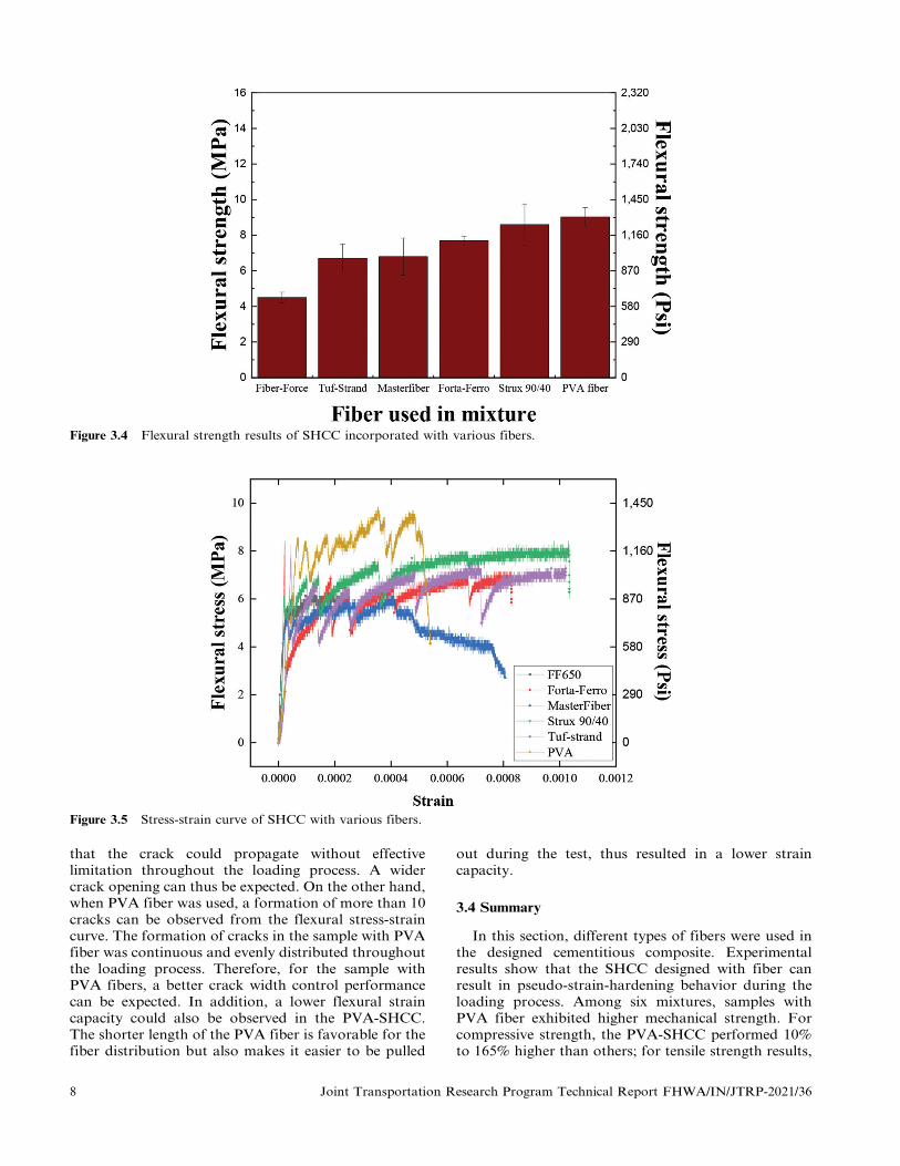
Figure 3.4 Flexural strength results of SHCC incorporated with various fibers.
Figure 3.5 Stress-strain curve of SHCC with various fibers.
that the crack could propagate without effectivelimitation throughout the loading process. A widercrack opening can thus be expected. On the other hand,when PVA fiber was used, a formation of more than 10cracks can be observed from the flexural stress-straincurve. The formation of cracks in the sample with PVAfiber was continuous and evenly distributed throughoutthe loading process. Therefore, for the sample withPVA fibers, a better crack width control performancecan be expected. In addition, a lower flexural straincapacity could also be observed in the PVA-SHCC.The shorter length of the PVA fiber is favorable for thefiber distribution but also makes it easier to be pulled
out during the test, thus resulted in a lower straincapacity.
3.4 Summary
In this section, different types of fibers were used inthe designed cementitious composite. Experimentalresults show that the SHCC designed with fiber canresult in pseudo-strain-hardening behavior during theloading process. Among six mixtures, samples withPVA fiber exhibited higher mechanical strength. Forcompressive strength, the PVA-SHCC performed 10%
to 165% higher than others; for tensile strength results,
8 Joint Transportation Research Program Technical Report FHWA/IN/JTRP-2021/36

the PVA-SHCC exceeded other sets for 24% to 65%;for flexural strength, the PVA-SHCC behaved 5% to101% higher than SHCC incorporated with otherfibers. The analysis of the flexural deflection showsthat the crack width control ability of the PVA fiber isstronger than the macro-fibers, since PVA fiber isstronger with higher aspect ratio and has a shorterlength which less prone to entangle. The existence of thePVA fiber can control the propagation of the crackwidth by generating multiple cracks, while less crackscould be formed in the sample with macro-fibers. It isalso observed that PVA-SHCC exhibited a lowerflexural strain capacity compared with others, whichcould be due to the shorter length of PVA that makes iteasier to pull out during the loading. In this project, thegoal is to develop a high-performance cementitiouscomposite with self-healing ability. It is favorable tochoose a fiber with stronger crack width control abilitywhich could limit the propagation of the cracks andpotentially increase the efficiency of the self-healing.Therefore, PVA fiber is more suitable for this specificpurpose and will be used in the following study aboutthe evaluation of the autogenous healing performance.
4. INTERNAL CURING AGENT-BASED SHCC
4.1 Objective
Based on the literature review, it has been concludedthat water is one of the indispensable factors that affectself-healing. However, due to the limited supply of freewater inside the hardened concrete, most of theproducts contributing to the self-healing process (suchas calcium hydroxide and calcium carbonate) can onlyform on the outer surfaces of the elements and are thusvulnerable to leaching. As such, the concept of internalcuring is introduced to serve as internal water reservoirsto enhance self-healing efficiency. In this project, ahypothesis is proposed that the incorporation of theinternal curing agent can improve the self-healingperformance of the designed concrete. This theory isexamined in this chapter by a series of tests, and arecommendation for the mixture design is provided.
4.2 Experimental Method
Three types of internal curing agents, Zeolite, light-weight aggregate, and SAP are used and evaluated.
Among them, the zeolite and lightweight aggregate areexpected to serve as internal water reservoirs which cansupply water internally. And the SAP is incorporated toact as the internal sealing agent that could swell andblock the crack from the inside.
In the first part of this study, zeolite was firstly usedto verify our theory. Then, the lightweight aggregatewas incorporated to compare with zeolite, and themechanism of the influence of the internal curing agenton self-healing was investigated.
4.3 Effect of Using Zeolite in SHCC
4.3.1 Mixture Composition of Zeolite-SHCC
The compositions of mixtures used to prepare SHCCspecimens are shown in Table 4.1. These included theordinary (Type I) Portland cement (OPC, BuzziUnicem USA), grade 100 slag cement (SC, SkywayCement Company), Class C fly ash (FA, Fly Ash DirectLtd.-Joppa Power Plant), silica sand (AGSCOCorporation), and polyvinyl alcohol (PVA) fibers(NYCON Corporation).
The water absorption capacity of the clinoptilolitezeolite (KMI Zeolite Inc, USA) particles was testas 18%. In this study, the zeolite was used to replacepart of the silica sand. Figure 4.6 presents the particlesize distribution of zeolite and silica sand. The waterabsorption capacity of zeolite is 18%. To have athorough understanding of the influence of the internalcuring aggregate on the performance of the self-healing,the replacing ratios for the sand were designed from0% to 30%. All mixes have the w/b of 0.32 and 2%
volumetric fraction of PVA fiber.
4.3.2 Mechanical Test
The SHCC samples were cured in the moisture-curing room for 10 days to decrease the probability ofthe shrinkage cracking. Then, the samples were movedto an environment-controlled chamber with 23¡2uCand 50% RH for another 40 days until testing.Mechanical properties, including compressive test andsplitting tensile test, were conducted. Three 50 mmcubes evaluated the compressive strength of specimensfrom various mixtures according to ASTM-C109. For thesplitting tensile test (ASTM-C496), 100 mm 6 200 mm
TABLE 4.1Compositions of concrete mixtures (proportions expressed as fraction of cement weight)
Mix OPC SC FA Zeolite Silica Sand w/b1 PAV Fiber (Volume %) Zeolite Replacement (%)2
Z_0 1 0.15 0.15 0 0.80 0.32 2 0
Z_75 1 0.15 0.15 0.06 0.74 0.32 2 7.5
Z_150 1 0.15 0.15 0.12 0.68 0.32 2 15
Z_225 1 0.15 0.15 0.18 0.62 0.32 2 22.5
Z_300 1 0.15 0.15 0.24 0.56 0.32 2 30
1Water-to-binder ratio.2Level of replacement of sand by zeolite (weight %).
Joint Transportation Research Program Technical Report FHWA/IN/JTRP-2021/36 9

cylindrical specimens were used. Three-cylinder andcubic specimens were prepared for each mixture. Thestrength measurements were averaged from the threereplicates of each mixture.
4.3.3 Self-Healing Evaluation by Non-Destructive Test
The SHCC samples were pre-damaged at the age of50 days and then exposed in the wet/dry condition toevaluate the self-healing performance. To induce thepre-damage in the specimens (100 mm 6 200 mmcylinders), the loading was applied in the circumferencedirection of the sample using splitting tensile method.The pre-loading of the specimens was applied 80% ofthe ultimate splitting tensile strength of each mixture toavoid the different degrees of the damage (or pre-cracks) among the specimens. After the pre-damage,the specimens were exposed to healing cycles (4 daysper cycle) with 2 days in a high moisture environment(100% RH) and 2 days in a moderate humidityenvironment (50% RH) for 7 cycles (28 days). Thedesign of the wet/dry cycles intends to simulate thenatural environment where the external water supply islimited.
After the healing period, the self-healing process ofthe specimens was evaluated via two non-destructivetests (NDT), including resonant frequency (RF) andultrasonic pulse velocity (UPV) tests. According toASTM C215, the torsional mode was adopted toconsider the geometric shape of the cylinder speci-mens for RF measurement. The RF measurementsetup consisted of a piezoelectric oscilloscope(GrindoSonic MK5, Penn Tool Co.), a vibrationdetector, a wooden ball, and sponge support, asshown in Figure 4.7
UPV test (NDE 360 Platform, Olson Instruments)was conducted according to ASTM-C597. The devicewas calibrated with a reference aluminum bar beforetesting. To eliminate human errors during the measure-ment, a custom-designed wooden frame was utilized,as shown in Figure 4.8. The transducers were pushedto contact both sides of the cylinder surface with aconstant force from springs. The high vacuum couplingagent was applied to erase the air void on the interfacebetween sensors and samples.
The sound samples were measured for RF and UPVbefore pre-damage. After imposing the 80% tensileloading to pre-damage the samples, the RF and UPVtest were conducted again. To attain the self-healingperformance in cementitious materials, RF and UPVwere conducted after 1st, 3rd, and 7th wet/dry cycles(4, 12, and 28 days after pre-damaged).
4.3.4 Properties of Zeolite-SHCC
4.3.4.1 Mechanical performance. Figure 4.1 presentsthe compression results of various zeolite replacingratios of SHCC samples. As the figure shows, com-pressive strength grows slightly as the zeolite contentincreases. The sample without zeolite incorporated has
Figure 4.1 Compressive strength of different samples.
Figure 4.2 Splitting tensile strength of different samples.
a strength of 69.2 MPa, while the high zeolite content(30%) raised to 80 MPa. The compressive strengthgains around 15% due to the extra water released fromthe internal curing agent for continuous hydration,which enhances the strength of the matrix. Thus, theimprovement of the degree of hydration is reflected inthe increase of compressive property.
Figure 4.2 presents the splitting tensile result ofdifferent SHCC samples. As can be seen that the tensilestrength of the sample is range from 7.54 MPa to7.98 MPa as the content of the zeolite increases. Theresult indicates that although zeolite is a high porositymaterials, it would not affect the tensile performancewith replacing ratio of up to 30%. The enhancement oftensile stiffness due to internal curing and incorporationof PVA fiber might compensate for the high porosityweakness.
10 Joint Transportation Research Program Technical Report FHWA/IN/JTRP-2021/36

4.3.4.2 Self-healing performance of zeolite-SHCC.The self-healing performance of SHCC samples wasevaluated via a resonant frequency test and ultrasonicpulse velocity test at each age of interest. The NDTresults of the sound sample were measured before thepre-damage imposed on the sample. The measurementswere also conducted after the sample was pre-damagedand underwent different wet/dry cycles, including 1, 3,and 7 cycles.
Recovery ratio %ð Þ
~NDTHealed{NDTPre{damaged
NDTsound|100% ðEquation 4:1Þ
Figure 4.3(a,b) depict the recovery results of theresonant frequency test and ultrasonic pulse velocitytest, respectively. It can be seen that the incorporationof the zeolite effectively improved the self-healingperformance. It is no surprise that the recovery ratioof both RF and UPV is increased with the wet/drycycles for all mixtures due to the further hydration ofun-hydrated cementitious materials. The benefit ofadding porous zeolite in cementitious materials is toincrease the bulk absorption capacity of the sample,which leads to the sample to absorb and store part ofthe external water under wet curing conditions.Consequently, the stored water can be slowly releasedfor continuous secondary hydration when the externalwater is unavailable. In addition, since the zeolite waspre-wetted before the mixing, it is also possible thatpart of the internal curing water was used for thehealing of the crack.
In Figure 4.3(a), it can be noted that the recoveryratio of the 1st cycle increases with the zeolite replacingratio increase; however, the SHCC with 30% zeoliteincorporation shows less healing performance thanothers. After 3 cycles, the sample with 15% and 22.5%
performed better recovery ratio than all other samples.It is worth to note that the RF recovery results of30% sample growth rapidly from 1 cycle (4 days) to3 cycles (12 days). The RF experiment result underwent
7 wet/dry cycles suggested that incorporating theinternal curing agent improves the healing performanceof the designed material, while the sample with 15% ofzeolite performs the best and shows around 6% recoveryratio. However, the healing performance decreased withthe zeolite replacing ratio increasing for the more zeoliteincorporated sample of 22.5% and 30%.
The UPV results can be seen in Figure 4.3(b). Afterthe first cycle, the UPV recovery ratio increases with thezeolite content up to 15%, and the healing performancedecreases after incorporating more internal curingagents. The SHCC with 22.5% zeolite exhibits a betterhealing performance of 4.1% on the 3rd wet/dry cycle.The 7th wet/dry cycle result reveals that the increasingtendency of recovery rate reaches the maximum for thesample with 15% zeolite; nevertheless, it decreasedafterward. The UPV result happened to have a similartrend with the RF outcome on the seven cycles, whichimplied that the optimal zeolite replacing ratio toimprove self-healing performance might be around 15%.
We have noticed that the healing performancedecreased after 15% incorporation. The phenomenamay be attributed to the densification of the cementi-tious matrix of high zeolite content SHCC block theexternal water for secondary hydration, which is theso-called ‘‘blocking effect.’’ To be more specific, partof the water stored in zeolite might be released duringthe early stage of hydration, which is expected as aninternal curing effect. The extra water provided by theinternal curing agent can enhance the hydration degreeof cementitious materials and further densify thecement matrix. Consequently, a dense cement matrixwould tend to block the water supply from the exter-nal environment, as Figure 4.4 shows. As mentionedabove, it is important for the sample to absorb waterfrom the external environment and use it for self-healing when the water supply is unavailable. A cementmatrix with a high hydration degree may inhibit theability of the sample to absorb and store water. Also,due to the dense matrix, the water release via aninternal curing agent might not be able to transport to
Figure 4.3 Self-healing performance at different Zeolite replacing ratios: (a) resonant frequency test and (b) ultrasonic pulsevelocity test.
Joint Transportation Research Program Technical Report FHWA/IN/JTRP-2021/36 11

Figure 4.4 Schematic of blocking effect.
Figure 4.5 The tensile strength retention ratio of differentSHCC sample after 7 cycles.
the crack for healing. Moreover, as the amount of theinternal curing water carried by the zeolite increase,larger portion of the cement particles was consumedduring the early age hydration. Consequently, lessamount of the cement would be available for secondaryhydration during the self-healing period. Thus, once theincorporation rate of the internal curing agent is higherthan the balance point (15% in this study), the increaseof the amount of the internal curing agent might leadto a negative effect.
The strength recovery factor is defined as sreloaded/sultimate, where sreloaded is the reloaded tensile splittingstrength, and sultimate is the ultimate strength. After thenon-destructive evaluations, the post-7-cycles SHCCsamples were reloaded using a splitting tensile test.Figure 4.5 presents the tensile strength recovery factorof different SHCC samples after 7 wet/dry cycles. Asshown in Figure 4.5, the recovery factor of all samplesis higher than 0.73. The strength recovery factor ofplain SHCC sample without zeolite incorporated isaround 0.84. The 7.5% sample performed the besttensile recovery of 0.98. Nevertheless, as the zeolitecontent increase, the recovery factor decreased. It mightoccur due to the blocking effect, which limited theinfiltration of external water into samples as discussedin the previous section. Also, due to the higherhydration degree of the sample with larger zeolitecontent, limited amount of the cement would beavailable after the pre-damaging process.
4.4 Effect of Using Lightweight Aggregates in SHCC
4.4.1 Mixture Composition of LWA-SHCC
To further study the mechanism of the influence ofinternal curing aggregates on the healing of thedesigned composite, lightweight aggregate was usedas an internal curing agent and compared withzeolite. Table 4.2 presents the mixture design for the
LWA-SHCC. Two sets of mixtures with zeolite werealso designed to compare with the LWA-SHCC.
4.4.2 Mechanical Test
The fresh cementitious materials were then cast into50 mm cubic molds for the compressive test, 240 mm 660 mm 6 15 mm plate for four-point bending test,and dog-bone specimens for uniaxial tensile test andself-healing evaluation, respectively. The samples werede-molded after 24 hours and cured in a 100% relativehumidity chamber for 28 days.
4.4.3 Self-Healing Evaluations
To evaluate the autogenous healing performance ofthe sample, a designated level of damage was induced to
12 Joint Transportation Research Program Technical Report FHWA/IN/JTRP-2021/36

TABLE 4.2Mixture design (by weight of cement) for the study of internal curing aggregates
PAV Fiber Lightweight
Mix OPC-I Blast Furnace Slag Fly Ash w/b1 (Volume %) Zeolite Aggregate Sand Replaced (%)2
R_0 1 0.15 0.15 0.35 2 0 0 0.80 0
L_15 1 0.15 0.15 0.35 2 0 0.06 0.74 15
L_30 1 0.15 0.15 0.35 2 0 0.12 0.68 30
Z_15 1 0.15 0.15 0.35 2 0.06 0 0.74 15
Z_30 1 0.15 0.15 0.35 2 0.12 0 0.68 30
1Water-to-binder ratio.2Internal curing agent replaced sand rate (weight %).
Figure 4.6 Experimental procedure for autogenous healing evaluation.
Figure 4.7 Result of 28 days compressive test.
the sample. A tensile strain of 0.5% was chosen as thepre-loading level to induce cracking on the specimens.After the pre-loading, samples were exposed to wet/drycycles to simulate the natural environment of rainingand sunny, which has a discontinuous water supply.Each wet/dry cycle includes two days curing at 100%
relative humidity, and another 2 days at 50% relativehumidity. The total healing period was kept at 28 days(7 cycles).
The autogenous healing performance was evaluatedthrough a resonant frequency test and optical micro-scope. The measurement of resonant frequency is basedon ASTM C215 (Subcommittee C09.64, 2019). Thecracks were examined through an optical microscope.By using image analysis software (Image J), the sealingof the crack mouth can be observed and quantified.For each crack on the specimen, test points were takenat an equal distance of 200 mm. Changes in the crackwidth for all the test points were analyzed before andafter the healing period. The experimental procedure isshown in Figure 4.6.
4.4.4 Properties of LWA-SHCC
4.4.4.1 Mechanical performance. After 28 days ofmoisture curing, compressive and uniaxial tensile testwere conducted. Figure 4.7, Figure 4.8, and Figure 4.9present the compressive, flexural and uniaxial tensiletest results, respectively. It can be observed that theincorporation of internal curing agents slightly
increased the compressive and flexural performancewhile the tensile strength stayed almost consistent.
Moreover, by comparing the two types of internalcuring agents, the sample with zeolite exhibited a morepronounced improvement in compressive and flexuralstrength. The phenomena may be attributed to thehigher water absorption capacity of zeolite. A con-siderable amount of water was supplied by zeolite,leading to a denser cementitious matrix, which isfavorable for mechanical behavior. When it comes tothe uniaxial tensile test, the incorporation of zeolite or
Joint Transportation Research Program Technical Report FHWA/IN/JTRP-2021/36 13

LWA was expected to be detrimental to tensileperformance because of the larger particle sizes ofinternal curing agents. The porous agents can act asflaws in the cement matrix when uniaxial tensile loading
was applied. The higher hydration degree due to theinternal curing compensated the negative effect ofadding large internal curing agents.
4.4.4.2 Self-healing performance. As shown inFigure 4.10, after 28 days of healing, all the samplesshowed certain levels of healing. Among this, samples withinternal curing agents exhibited a more significant self-healing ability compared with the reference group.Specifically, while the R_0 had 12.6% of the recoveryratio, the samples L_15, L_30, Z_15, and Z_30 showed ahigher recovery ratio of 18.3%, 23.8%, 25.3%, and 21.3%,respectively. The recovery ratio increased with the increasein the replacement level of lightweight aggregates. Theeffect of zeolite was somewhat more complicated. It hadthe highest recovery ratio at the replacement level of 15%,but there was a decrease in the recovery ratio at thereplacement of 30%, which will be discussed later.
Morphology observation was performed by using anoptical microscope. Figure 4.11 shows the healing ofcracks throughout the wet/dry cycles. As the curingcycles increased, the healing of the micro-cracks can beobserved. The optical microscopic image of cracks wascompared before and after 7 wet/dry cycles of curing tofurther quantify and compare the healing efficiency.The crack width reduction ratio (Equation 4.2) wasused to represent the healing extent of the crack mouth.The result is shown in Table 4.3.
Reduction ration %ð Þ
~Original crack width{Healed crack width
Original crack width
|100% Equation 4:2ð Þ
According to the result of the morphology observa-tion, all the mixtures showed complete sealing for crackwidths below 20 mm due to the self-healing behavior.
Figure 4.8 Result of 28 days flexural test.
Figure 4.9 Result of 28 days uniaxial tensile test.
Figure 4.10 Recovery ratio of designed materials based on resonant frequency measurement.
14 Joint Transportation Research Program Technical Report FHWA/IN/JTRP-2021/36

Figure 4.11 Healing of cracks throughout wet/dry cycles (from mixture R-0).
TABLE 4.3Crack width reduction ratio of different mixtures
Crack Width Range (mm) R_0 L_15 L_30 Z_15 Z_30
0,10
10,20
20,30
30,40
40,50
.50
100
100
43.52
42.79
25.27
20.85
100
100
44.24
40.96
27.70
34.09
100
100
44.73
55.73
31.67
23.64
100
100
88.61
59.69
46.28
49.09
100
95.56
48.17
50.3
33.96
31.28
For R_0, the reduction ratio dropped to around 40% atthe crack width of 20,40 mm and remained at a lowlevel of around 20% above 40 mm. With the incorpora-tion of pre-wetted internal curing agents effectivelyincreased the crack width reduction ratio for all crackwidth ranges. Z_15 achieved the best healing perfor-mance among all groups. The reduction ratio was almosttwo times higher than the other groups at 20,30 mm.Even above 50 mm, it still retained around 50% of thecrack width reduction ratio.
4.4.4.3 Pore structure of the internal curingaggregates. Internal curing agents under satura-ted surface-dry (SSD) condition were tested toevaluate the water desorption kinetics by monitoringthe change of the weight under different designed
conditions. The normalized moisture content defined asMass Water
, is used to quantify the extent of48h Water Absorptionthe water desorption. A normalized weight of 1.0represents the saturated internal curing agent. Theresult of the water desorption kinetic test is shown inFigure 4.12. It can be seen that zeolite and LWAreached equilibrium after 8 hours at a relative humidityof 50%. Furthermore, 80% and 90% of their absorbedwater were released, respectively. It is expected thatsince LWA and zeolite have been used to supply waterto reduce the early age shrinkage, a high release rate ofwater is required under such a relative humidity level(Paul & Lopez, 2011). Afterward, when samples weremoved to the chamber with 10% relative humidity,zeolite released another 10% of its absorbed water while
Joint Transportation Research Program Technical Report FHWA/IN/JTRP-2021/36 15
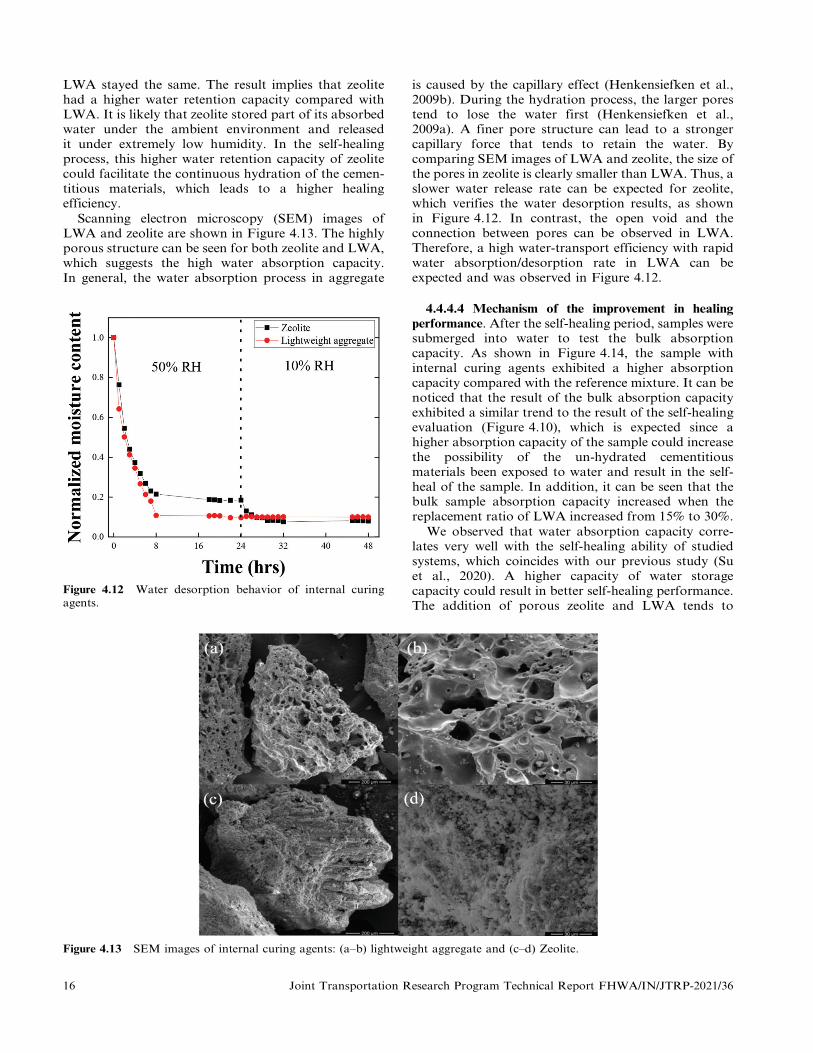
LWA stayed the same. The result implies that zeolitehad a higher water retention capacity compared withLWA. It is likely that zeolite stored part of its absorbedwater under the ambient environment and releasedit under extremely low humidity. In the self-healingprocess, this higher water retention capacity of zeolitecould facilitate the continuous hydration of the cemen-titious materials, which leads to a higher healingefficiency.
Scanning electron microscopy (SEM) images ofLWA and zeolite are shown in Figure 4.13. The highlyporous structure can be seen for both zeolite and LWA,which suggests the high water absorption capacity.In general, the water absorption process in aggregate
is caused by the capillary effect (Henkensiefken et al.,2009b). During the hydration process, the larger porestend to lose the water first (Henkensiefken et al.,2009a). A finer pore structure can lead to a strongercapillary force that tends to retain the water. Bycomparing SEM images of LWA and zeolite, the size ofthe pores in zeolite is clearly smaller than LWA. Thus, aslower water release rate can be expected for zeolite,which verifies the water desorption results, as shownin Figure 4.12. In contrast, the open void and theconnection between pores can be observed in LWA.Therefore, a high water-transport efficiency with rapidwater absorption/desorption rate in LWA can beexpected and was observed in Figure 4.12.
4.4.4.4 Mechanism of the improvement in healingperformance. After the self-healing period, samples weresubmerged into water to test the bulk absorptioncapacity. As shown in Figure 4.14, the sample withinternal curing agents exhibited a higher absorptioncapacity compared with the reference mixture. It can benoticed that the result of the bulk absorption capacityexhibited a similar trend to the result of the self-healingevaluation (Figure 4.10), which is expected since ahigher absorption capacity of the sample could increasethe possibility of the un-hydrated cementitiousmaterials been exposed to water and result in the self-heal of the sample. In addition, it can be seen that thebulk sample absorption capacity increased when thereplacement ratio of LWA increased from 15% to 30%.
We observed that water absorption capacity corre-lates very well with the self-healing ability of studiedsystems, which coincides with our previous study (Suet al., 2020). A higher capacity of water storagecapacity could result in better self-healing performance.The addition of porous zeolite and LWA tends to
Figure 4.12 Water desorption behavior of internal curingagents.
Figure 4.13 SEM images of internal curing agents: (a–b) lightweight aggregate and (c–d) Zeolite.
16 Joint Transportation Research Program Technical Report FHWA/IN/JTRP-2021/36

Figure 4.14 Bulk sample water absorption capacity.
increase the bulk absorption capacity of the sample(Figure 4.14), which makes it more likely to absorb andstore part of the external water when it is under wetcuring condition (Kou et al., 2014). Consequently, thispart of the stored water can be slowly released forcontinuous secondary hydration and precipitation ofthe calcium carbonate when the external water is nolonger available. Besides, if we took a closer look at theeffect of zeolite when the content of zeolite increasedfrom 15% to 30%, the water absorption capacitydecreased, and its decreasing water absorption com-promised the healing performance. Considering thewater absorption capacities of zeolite and LWA are18.00% and 13.64%, respectively, mixture Z_30 isexpected to have the highest water absorption capacity.However, the test result shows that this is not the case.In fact, mixture Z_30 exhibited the lowest absorptioncapacity among all the samples with internal curingagents, even though the mechanical tests have alreadyproven that Z_30 did have the most robust matrix dueto a larger amount of internal curing water carried by30 wt% of zeolite. The reason may be the existence ofthe balance between the incorporation of porous agentand internal curing effects. When the internal curingeffect is under a certain threshold, the incorporation ofa porous curing agent will increase bulk absorptioncapacity. In contrast, when the amount of internalcuring water beyond that threshold, the increment incompactness of the matrix due to the internal curingeffect starts to block the external water from absorbingby the bulk sample, the so-called water blockingeffect, which leads to a lower absorption capacity(Su et al., 2020).
Based on the result of the internal curing agents’desorption test, as shown in Figure 4.12, zeolite has ahigher water retention capacity compared with LWA.LWA tends to release all its absorbed water in theambient environment, while zeolite can store part of it.Also, the SEM images show that zeolite has finer porescompared with LWA (Figure 4.13), leading to a slowerwater release rate. These features of zeolite are
favorable for the improvement of self-healing since itis vitally essential for the internal curing agent to hasthe ability to supply water when the external moisture islimited continuously. The TGA measurement showsthat samples incorporated with zeolite exhibited ahigher degree of hydration, which confirms the strongerinternal curing effect and secondary hydration. It canbe noticed that, although Z_30 had a lower bulk sampleabsorption capacity than the mixtures with LWA(Figure 4.14), it still led to the comparable self-healingperformance compared with LWA (Figure 4.10 andTable 4.3) owning to its high water retention capacityand slower water release rate (Figure 4.12).
4.5 Effect of Using Superabsorbent in SHCC
4.5.1 Experimental Design
According to the literature review, autonomoushealing of the concrete is based on the artificiallyincorporated healing agents which allows the completehealing of cracks larger than several hundreds ofmicrometers, while the autogenous healing exhibited aless healing capacity of less than 100 mm.
In order to prevent the overestimation of theabsorption capacity of the SAP in concrete mixture,the robustness of the SAP was evaluated. The SAP usedin this study is a commercially available SAP Floset 27.Various dosages of the superplasticizer, hydrationaccelerator and fly ash were designed, and the absorp-tion behavior of the SAP was tested by the filtrationtest and void size analysis.
A filtration test was performed to evaluate theinfluence of superplasticizer and hydration acceleratoron the water absorption behavior of SAP. Theconcentration of the SP and accelerator were rangedfrom 0 to 2.0 wt% and 0 to 1.0 wt%, respectively.A constant mass of the SAP of 0.2 g was prepared foreach test. The test setup is shown in Figure 5.4. TheSAP was filtrated by a funnel after 15 minutes soakingin the 100 mL DI water with different concentrations ofthe superplasticizer or hydration accelerator. A pumpwas used to provide a constant pumping pressure toaccelerate the filtration process. The absorption capa-city of the SAP was calculated by Equation 4.2.
Absorption capacity g=gð Þ~ mliquid
mSAP
ðEquation 4:2Þ
Where mliquid is the mass of the liquid that isabsorbed by the SAP and the msap is the original massof the SAP that adds into the solution.
Void size analysis was conducted to analyze the sizeof the pores that leave by SAP after it releases theabsorbed water. The void size left by the SAP can beused as an index to represent the absorption behaviorof the SAP during the mixing and curing process.Different dosages of superplasticizer, hydration accel-erator, or fly ash were designed. Samples with fourdifferent fly ash to cement contents (FA/CEM) range
Joint Transportation Research Program Technical Report FHWA/IN/JTRP-2021/36 17

from 0 to 1.2 were prepared. Based on the technicaldata sheet provided by the manufacturers, the designeddosages for superplasticizer and accelerator wereranged from 0 to 2 wt% and 0 to 1.79 wt%, respectively.All the sample was incorporate with 0.25 w% of theSAP and the water to cement ratio was 0.4. Thesamples were de-molded after 24 hours and cured in thelaboratory condition for 7 days.
After the curing, the samples were cut into 25.4 mmcubic by a diamond saw, and calcinated under 600uCfor 1 hour to decompose the SAP particles. Then,acetone was used to clean the surface of the sample. Toenhance the contract between the void and the matrixunder the microscope, the surface of the sample wascolored by black marker, and then pre-treated by thebarium sulfate powder. To evaluate the average voidsize on the surface of the sample, the microscopicimages were analyzed by the software Image J.
A water flow test was designed to evaluate the self-sealing performance of the SAP in concrete materials.Cement paste with 1 wt% of the SAP was cast into76.2 mm (diameter) 6 152.4 mm cylinder and curedin the laboratory environment for 7 days. A referencesample without the addition of SAP was also prepared.The water to cement ratio of the mixtures was 0.4.After the 7 days curing, splitting tensile loading wasconducted to pre-crack the sample. The crack widthwas controlled by two steel rings as 0.16 mm. Theexperimental setup includes a water tank, PVC tube,rubber tube, balance and computer, as shown inFigure 5.5. The water tank can continuously supplywater, while a rubber tube connected to the PVC tubecontrols the water level to make sure the constant of thewater pressure to the testing sample. Balance and thecomputer are used to monitor and record the weight ofwater passing through the sample with time.
4.5.2 Result and Discussion
4.5.2.1 Robustness of SAP. Results of the robustnessevaluation of SAP are shown in Figures 4.15, 4.16, and
4.17. For the filtration test, as can be seen inFigure 4.15(a) and Figure 4.16(a), the absorptioncapacity of the SAP decreased from 287.5 g/g to102.6 g/g as the dosage of the superplasticizer increasedfrom 0 to 2 wt%. On the other hand, when 1 wt% of theaccelerator was used, a much more aggressive inhibitioncan be observed, where the absorption capacity of theSAP was decreased down to 8.4 g/g. Therefore, it can beconcluded that the presence of the superplasticizer orhydration accelerator can effectively inhibit the swellingof the SAP particles. The result was further verified bythe void size analysis, as shown in Figure 4.15(b) andFigure 4.16(b). During the mixing process, the dry SAPparticles swelled by absorbing part of the mixing water.Afterward, the absorbed water was released for cementhydration as the relative humidity decrease, whichcaused the shrinkage of the SAP particles and generatedempty voids inside the cementitious matrix. Therefore,the average void size can be used to analyze theabsorption behavior of the SAP in fresh concrete. Theincorporation of the superplasticizer or accelerator ledto a smaller average void size, which indicates that theswelling of the SAP was inhibited by the additives thatwere incorporated. On the contrary, as shown in theFigure 4.17, the addition of the fly ash led to anincrease in the average void size. This could be due tothe low solubility of the fly ash compared with cement.
+Since the presence of cations such as Ca2 and Al3+ wasreported to have an inhibiting effect on the swelling ofthe SAP, the low solubility of the fly ash reduced thecation concentration of the pore solution, whichpromoted the absorption capacity of the SAP.
It is worth noting that even though the result of thefiltration test shows that the superplasticizer andaccelerator can aggressively reduce the absorptioncapacity of the SAP, only minor influence was observedfrom the void size analysis. Especially for the hydra-tion accelerator, only 3.2% reduction was observedwhen the dosage of the accelerator was 1.79 wt%.Furthermore, the average void size was reduced for10.0% when 2 wt% of the superplasticizer was used.
Figure 4.15 Evaluation of the SAP robustness under various superplasticizer dosage: (a) filtration test and (b) void size analysis.
18 Joint Transportation Research Program Technical Report FHWA/IN/JTRP-2021/36

Figure 4.16 Evaluation of the SAP robustness under various hydration accelerator dosage: (a) filtration test and (b) void sizeanalysis.
Figure 4.17 Evaluation of the SAP robustness under variousfly ash content.
Figure 4.18 Water flow rate of the testing samples.
Similarly, when the fly ash to cement ratio was 1.2, only8.1% increment on the average size was found.Therefore, it can be concluded that the SAP is relativelyrobust under various environmental conditions. How-ever, during the mixture design with SAP, the use ofsuperplasticizer, hydration accelerator and fly ashshould be considered as a factor that may influencethe efficiency of the internal curing.
4.5.2.2 Self-healing performance of SAP. Accordingto the data recorded by the computer, the water flowrate can be calculated by the weight of water passingthrough the sample per unit time, as shown inFigure 4.18. The cumulative passing water with timewas also acquired, as shown in Figure 4.19.
It can be observed from the result that theincorporation of SAP effectively controlled the seepingof the water compared with the plain cement sample.In Figure 4.18, it can be noticed that compared with
the reference mixture, the sample with SAP has a higherwater flow rate at the beginning. It could be due to thelarge pores left by drying SAPs that favor the passingof the water. However, it can be noticed that within60 seconds, the water flow rate decreased from over0.2 g/s to 0.02 g/s, which is already lower than the plaincement sample. In this process, there are two mechan-isms for the reduction of the water flow rate. Firstly,once the SAPs embedded inside the cement paste comein contact with water, it will start to absorb water andprevent part of the water from passing through thesample. Secondly, after the SAP absorbs water, theswelling effect of the SAP can seal the crack and blockthe further seeping of the water. In Figure 4.19, it canbe observed that the passing of water was effectivelycontrolled for the sample with SAP. On the contrary,the water passing through the sample without SAPincreased almost linearly with time. The total weight ofthe passing water was over 150 g after 3,000 s, which is7 times higher than the sample with SAP. Therefore, itcan be concluded that the self-sealing effect of the SAP
Joint Transportation Research Program Technical Report FHWA/IN/JTRP-2021/36 19

Figure 4.19 Weight of the cumulative passing water.
is capable of controlling the seepage of the externalwater. If the cracked concrete is exposed to the outdoorenvironment, such as precipitation or groundwater,SAP inside the concrete will form a soft gel that fills inthe formed cracks, preventing the further waterpenetration, which is called self-sealing. The self-sealingoccurs rather rapidly (usually within a few minutes inthe presence of external water). Afterward, the waterretained in SAP triggers the hydration and carbonationat the surface of cracks, leading to long-term self-healing.
4.6 Summary
In this chapter, effects of the incorporation ofinternal curing agents into the designed cementitiouscomposite on the self-healing performance were tested.Experimental results show that the internal curingaggregates can enhance the healing efficiency byproviding water internally to accelerate the autogenoushealing.
In the evaluation of the internal curing aggregates,it was found that the cementitious composites withporous curing aggregate had better compressivestrength than the reference sample. The extra watersupplied by the pre-wetted zeolite or lightweightaggregate could enhance the degree of hydration toform more C-S-H gel and a strong cement matrix. Thesamples show an over 15% compressive strengthimprovement for the cementitious composites samplewith zeolite and a 6% improvement with lightweightaggregate.
Evaluation of the self-healing performance showsthat the addition of the internal curing aggregateimproved the healing of the sample. The use of thezeolite could increase the healing ratio from around2.0% to over 5.0% after 7 wet/dry cycles (28 days) basedon two non-destructive tests. Results from the experi-ments suggests that the optimal zeolite replacing ratio
for sand may be 15 wt%. In addition to zeolite, aconventional internal curing agent, the lightweightaggregate was also incorporated and the properties ofthe SHCC were compared with the zeolite. The resultsindicate that the use of the lightweight aggregateimproved the healing efficiency of the SHCC, but theimprovement was not as significant as zeolite. The porestructure analysis suggests that the zeolite has a finerpore size compared with LWA. During the healingperiod, it is capable of slowly but continuously supply-ing water to cementitious materials when the externalwater supply is unavailable. The continued watersupply led to a better autogenous self-healing perfor-mance compared with lightweight aggregate.
Evaluation of the SAP indicated that the absorptionbehavior of the SAP could be influenced by thesuperplasticizer, hydration accelerator, and fly ash.However, only a minor influence of less than 10% wasobserved. Therefore, it can be concluded that SAP isrelatively robust under the designed environmentalconditions. For the self-sealing effect of the SAP, adramatic reduction in the water flow rate from 0.2 g/sto 0.02 g/s was observed within 60 seconds of the testwhen the SAP is incorporated. In addition, the 5 hourscumulative passing water of the reference sample was7 times higher than that with the incorporation of SAP.In summary, experimental results indicated the effec-tiveness of using SAP as a self-sealing agent in concretematerials.
5. RHEOLOGY CONTROL OF SHCC
5.1 Introduction
Rheological control is critical for optimize the fiberdistribution and to realize the micromechanical designof SHCC. In fiber reinforced cementitious composite,a higher solid volume fraction can lead to a higherfrictional force between fiber and other solid particles.Therefore, in the design of the high ductility cementi-tious composite, low water to cement ratio is generallyused to ensure the fiber distribution and fiber-matrixinterface. However, considering the economic efficiencyand practical application, a relatively high-watercontent of 0.35 is used in the design SHCC. Thus, thequality of the fiber distribution would be a concern andaffect the ductility of the SHCC. In this session, wediscuss the efficiency of two approaches on rheologycontrol, including the addition of SAPs and adjusted byvarious viscosity-modified agents. The mechanicalperformance of the SHCC was also evaluated andreported in this chapter.
5.2 Effect of SAP on the Rheology of SHCC
In this part of the study, we first present the influenceof the SAP on the rheology properties of the cementpaste. The plastic viscosity of the cement paste wascalculated and discussed. Moreover, the mini-slumptest was performed to identify the workability of SAP
20 Joint Transportation Research Program Technical Report FHWA/IN/JTRP-2021/36

based SHCC, and the mechanical properties of thesample were evaluated.
5.2.1 Materials and Methods
A commercially available SAP (Floset 27 CS) waschosen in this study. The selected SAP is a cross-linkedcopolymer of acrylamide and acrylate in a powder formwith a mean particle size of 194 mm, as shown inFigure 5.11. The absorption capacity in the syntheticcement pore solution was measured using the tea-bagmethod, as described in (Mechtcherine et al., 2018). Thesynthetic cement pore solution was prepared based onprevious work (Kjeldsen et al., 2006). As shown inFigure 6.1, the SAPs absorbed the synthetic cementpore solution and reached a plateau rapidly while theabsorption of SAPs in DI water kept increasing,showing no sign of saturation within the investigatedtime range. The absorption capacity of the SAP in DIwater was much higher than that in synthetic cementpore solution. It can be due to the existence of thecations such as Ca2+ that reduced the water retentioncapacity of the SAP (Kang et al., 2018). The plateauvalue in the cement pore solution is around 35 g/g,representing that 35 g of solution absorbed by the unitweight (1 g) of dry SAP powders, and SAPs reached90% of the plateau value at 3 minutes after the SAPsfirst came into contact with the solution.
5.2.2 Rheological Measurements
As SAP absorbs the water and reduces the free waterin the cement matrix, it will significantly alter theworkability. It is necessary to evaluate the influence ofSAP on the rheological properties. All rheologicalcharacterization was performed on a temperature-controlled, stress-controlled rotational rheometer witha 4-blade vane geometry set at a constant temperatureof 25uC. The rheological test started with a pre-shearingto ensure that all the samples were at a reproduciblereference state. The sample was left to rest for 120 s to
allow for stress relaxation and followed by a linearshear ramp to obtain a flow curve. The shear stressresponse was recorded. From the flow curve, the yieldstress and plastic viscosity were obtained using theBingham model.
t~t0zgpl _c
Where t is shear stress, c is shear rate, t0 is dynamicyield stress, and gpl is plastic viscosity.
5.2.3 Experimental Result
A downward portion of the curve was fitted with theBingham model. The yield stress is the intercept withthe vertical axis (when the shear rate is 0) and theplastic viscosity is the slope of the curve (constantthroughout the shear rate range considered). Theplastic viscosity and dynamic yield stress increasemonotonically with the addition of SAP as shown inFigure 5.1. The result shows that as the dosage of theSAP increased from 0% to 0.24 wt% of cement, theplastic viscosity showed a dramatic improvement ofover 56%. Based on the experimental result, theincorporation of the SAP could improve the fiberdistribution since it can increase the viscosity of themixture and the frictional force between fiber and othercementitious composite components during the mixingprocess. To further verify the influence of SAP on theperformance of SHCC, mechanical tests were con-ducted and presented in Section 5.2.5.
5.2.4 Mini-Slump and Viscosity Test Results of SAPBased SHCC
To study the influence of the SAP on the freshproperties of the SHCC, mini-slump and viscosity testswere conducted. The mixture composition is shown inTable 5.1. After the raw materials were prepared, thecement, slag, fly ash, sand and SAP powder were drymixed for 3 minutes. Then, water was added for the wetmixing for 3 minutes. After the wet mix, a partial of the
Figure 5.1 Flow curve of SAP cement (left), the effect of SAP on the plastic viscosity and dynamic yield stress of cement paste(right).
Joint Transportation Research Program Technical Report FHWA/IN/JTRP-2021/36 21

TABLE 5.1Mixture composition for the evaluation of slump and viscosity of SAP-SHCC
Mix OPC-I Blast Furnace Slag Fly Ash w/b* Fiber (Volume %) Sand SAP
2%PVA
2%PVA+0.166SAP
2%PVA+0.664SAP
1
1
1
0.15
0.15
0.15
0.15
0.15
0.15
0.35
0.35
0.35
2
2
2
0.8
0.8
0.8
0
0.166
0.664
Figure 5.2 Viscosity evaluation of the SHCC based SAP.
Figure 5.3 Mini-slump test for SHCC with 0.664% SAP.
TABLE 5.2Result of the mini-slump test
Mixture Ref 0.166% 0.644%
Diameter (inch) 6.188 5.625 –
mortar was taken out for viscosity measurement untilthe 15th minute (after adding water). The rest of thematrix was constantly mixed for 2 more minutes beforeadding the fiber. As the SHCC were well mixed, thefresh SHCC was used for the mini-slump test. Theresults are shown in Figures 5.2 and 5.3 and Table 5.2.
It can be seen from the Figure 5.2 that the additionof the SAP effectively increased the viscosity of theSHCC mixture from around 1,800 cP to over 10,000 cP,which is favorable for the improvement of the fiberdistribution. From Table 5.2, it can be found that theaddition of the 0.166% SAP reduced the diameter of themini-slump for 9.1%, which indicates the waterabsorption ability of the SAP could adjust the work-ability of the SHCC and prevent the overflow of themixture due to the use of the fly ash. However, it canalso be observed from Figure 5.3 that when the higherdosage of the SAP was used (0.664 wt%), the work-ability of the SHCC was un-satisfied, the viscosity andmini-slump of the SHCC with 0.664% SAP were unableto be measured due to the extreme low workability.
In this part of the study, the influence of the SAP onthe fresh properties of the SHCC was investigated.It was found that SAP can effectively increase theviscosity and decrease the workability of the mixtureusing small dosage of 0.166 wt%, which shows potentialin improving the fiber distribution. However, it wasalso observed that higher dosage of the SAP could leadto a poor quality of the mixture. It causes concern ofthe mechanical properties since SAP may negativelyaffect the hydration of the cementitious materials sinceit will absorb a large portion of the water and hinderthe early age hydration. Therefore, in the following
study, the mechanical performance of the SAP basedSHCC was examined. Extra water was designed andprovided for the SHCC mixtures with SAP incorpora-tion to ensure the early age hydration.
5.2.5 Mechanical Properties of SAP Based SHCC
5.2.5.1 Experimental design. To evaluate the influenceof the SAP on the mechanical properties, SHCCmixtures incorporated with SAP were designed, asshown in Table 5.3. Since SAP is used as internal curingagent that absorbs large amount of free water duringthe mixing process, extra water was provided for themixtures with SAP to ensure workability and early agehydration. 50 mm cubic, 240 mm 6 60 mm 6 15 mmplates, and dog-bone specimens were prepared for thecompressive test, four-point bending test, and uniaxialtensile test, respectively. The sample was demoldedafter 24 hours and cured in the moisture room untiltesting age.
5.2.5.2 Result and discussion. After 3 and 7 days ofthe moisture curing, the samples were subjected to
22 Joint Transportation Research Program Technical Report FHWA/IN/JTRP-2021/36

TABLE 5.3Mixture design for the evaluation of the mechanical properties of SHCC-SAP
Mix OPC-I Blast Furnace Slag Fly Ash w/b* Fiber (Volume %) Sand SAP
2%PVA
2%PVA+0.166SAP
2%PVA+0.664SAP
1
1
1
0.15
0.15
0.15
0.15
0.15
0.15
0.35
0.35+0.07
0.35+0.07
2
2
2
0.8
0.8
0.8
0
0.166
0.664
Figure 5.4 Compressive strength result for the SHCC-SAP.
Figure 5.5 Flexural strength result for the SHCC-SAP.
mechanical testing. The results are presented inFigures 5.4, 5.5, and 5.6. It can be observed that theaddition of the SAP decreased the compressive strengthof the SHCC at both testing age of 3 and 7 days. When0.166% of the SAP was used, the compressive strengthof the sample was decreased for over 25%, while ahigher dosage of the SAP could further decrease thestrength for another 15%. The adverse influence ofthe SAP on compressive strength could be due to theincreased porosity inside the matrix which was resultedin the swelling and shrinking of the SAP particles. TheSAP particles absorbed water in the fresh mixture andthe swelling effect increased its volume. Later, as the
cement matrix got harden, releasing the absorbed waterfrom the SAP left large pores inside the system.Therefore, a lower compressive strength can beexpected. Similar phenomenon was also found fromthe flexural test, as the size of the pore and the porosityincreased, the strength performance was adverselyaffected. In terms of the flexural deflection, the highdosage of the SAP incorporation reduced the ductilityof the SHCC, while the addition of the 0.166% SAPperformed similar as the reference sample. On the otherhand, it can be noted that the uniaxial tensile strengthof the sample with 0.166% SAP exhibited a slightlyhigher tensile strength and further increasing the dosage
Joint Transportation Research Program Technical Report FHWA/IN/JTRP-2021/36 23

Figure 5.6 Tensile strength result for the SHCC-SAP.
TABLE 5.4Experiment dosages of different VMA
Reference VMA 358 (,225 cP) (%) VMA 362 (,570 cP) (%) VMA 450 (,2,270 cP) (%)
VMA Percentage 0% 0.1
0.2
0.3
0.5
1.0
0.1
0.2
0.3
0.5
1.0
0.1
0.2
0.3
0.5
1.0
of the SAP resulted in a reduction of the tensileperformance. This result was due to the voids left by
the SAP and the improvement of the fiber distribution.
The empty space that was occupied by the swelled SAP
could acted as flaws in the matrix that can trigger the
formation of multiple cracks. Initially, the strong
SHCC matrix can generate limited number of cracks
that were bridging by the fibers was discussed in the
Section 3.1. The number of cracks was tightly related to
the amount of fiber that can contribute to the ductility
of the sample. The existence of the voids left by SAP
particles increased the possibility of forming more
cracks in the matrix during the loading process, which
resulted in a better tensile performance. Moreover, as
mentioned in Section 5.2.3, the increase on the viscosity
of the mixture by SAP is favorable for the improvement
of the fiber distribution which contributes to the higher
tensile strength. However, as the dosage of the SAP
increased, the existence of large number of voids started
to negatively affect the performance of the sample,
which resulted in a decrease of the tensile strength in the
sample with 0.664% of the SAP.
5.3 Effect of VMA on Rheological Control of SHCC
5.3.1 Experimental Method and Design
To improve the fiber dispersion and increase theinterfacial force between fiber and matrix, the commer-cially available viscosity modifying agents (VMA) wereused to adjusting the rheological properties of SHCC.
Three types of VMAs, including two thickening-type(methenamine based (VMA 358) and biphenyl-based(VMA 362) and binding types (methylpentane based,VMA 450) from BASF company, were utilized withthe apparent viscosity of 225 cP, 570 cP, 2,270 cP,respectively. The SHCC samples were tested withdifferent dosages of VMA (from 0.1% to 1%), as thetable shown in Table 5.4.
Figure 5.7 presents the experimental logistic of thetesting in this session. After the raw materials wereprepared, the materials were dry mixed using the mixerfor 3 minutes. Then, the water was added for the wetmixing for 3 minutes. Some mortar samples were takenout for viscosity measurement until the 15th minute(after adding water.) The rest of the matrix wasconstantly mixed for 2 more minutes before addingthe fiber. As the SHCC were well mixed, the freshSHCC were taken to test the mini-slump and cast in theflexural plate mold for the four-point bending test.
5.3.2 Result and Discussion
Figure 5.8 shows the results of viscosity measure-ments with various configurations of VMA. It can beseen that the VMA was able to increase the viscosity ofthe SHCC matrix. For VMA 358 and VMA 362, theviscosity of SHCC is located around 1,000 cP to 1,500cP at 15 minutes. However, for SHCC with VMA 450,the viscosity measurement was exceeded 1,500 cP.Specifically, the viscosity reached 2,500 cP as theVMA 450 dosage increased to 0.3%. Figure 5.9 showsthe viscosity results of 1% dosage of three types of
24 Joint Transportation Research Program Technical Report FHWA/IN/JTRP-2021/36
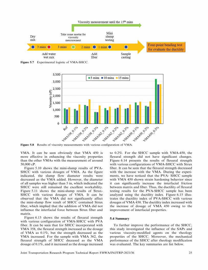
Figure 5.7 Experimental logistic of VMA-SHCC.
Figure 5.8 Results of viscosity measurements with various configuration of VMA.
VMA. It can be seen obviously that VMA 450 ismore effective in enhancing the viscosity propertiesthan the other VMAs with the measurement of around50,000 cP.
Figure 5.10 shows the mini-slump results of PVA-SHCC with various dosages of VMA. As the figureindicated, the slump flow diameter results weredecreased as the VMA added. However, the diameterof all samples was higher than 5 in, which indicated theSHCC were still remained the excellent workability.Figure 5.11 shows the mini-slump results of Strux-SHCC with various dosages of VMA. It can beobserved that the VMA did not significantly affectthe mini-slump flow result of SHCC contained Struxfiber, which implied that the addition of VMA did notinfluence the interfacial force between Strux fiber andmatrix.
Figure 6.13 shows the results of flexural strengthwith various configuration of VMA-SHCC with PVAfiber. It can be seen that for SHCC incorporated withVMA 358, the flexural strength increased as the dosageof VMA as 0.1%, but the strength decreased as theVMA increased. For the sample with VMA 362, theflexural strength of SHCC deceased as the VMAdosage of 0.1%, and it increased as the dosage increased
to 0.2%. For the SHCC sample with VMA-450, theflexural strength did not have significant changes.Figure 6.14 presents the results of flexural strengthwith various configurations of VMA-SHCC with Struxfiber. It can be seen that the flexural strength decreasedwith the increase with the VMA. During the experi-ments, we have noticed that the PVA- SHCC samplewith VMA 450 shown strain hardening behavior sinceit can significantly increase the interfacial frictionbetween matrix and fiber. Thus, the ductility of flexuraltesting results for the PVA-SHCC sample has beenanalyzed using the ductility index. Figure 6.15 illus-trates the ductility index of PVA-SHCC with variousdosages of VMA 450. The ductility index increased withthe increase of dosage of VMA 450 owing to theimprovement of interfacial properties.
5.4 Summary
To further improve the performance of the SHCC,this study investigated the influence of the SAPs andvarious viscosity-modified agents on the rheologyproperties of the SHCC. Moreover, the mechanicalperformance of the SHCC after rheology modificationwas evaluated. The key summaries are list below.
Joint Transportation Research Program Technical Report FHWA/IN/JTRP-2021/36 25

Figure 5.9 Comparison of the viscosity of three types of VMA (1%).
Figure 5.10 Results of mini-slump test with various configuration of VMA-SHCC with PVA fiber.
N Evaluation of the influence of the SAP on the rheology of
cement paste shows that as the dosage of the SAP
increased from 0% to 0.24 wt% of cement, the plastic
viscosity showed a dramatical improvement of over 56%,
which suggest that the incorporation of the SAP may be
able to improve the fiber distribution since it may
increase the frictional force between fiber and another
component of the cementitious composite during the
mixing process.
N Fresh properties of the SHCC could be adjusted by
the use of the SAP. However, when a higher dosage
of the SAP was used, it could negatively affect the quality
of the mixture, especially at an early age due to the
large water absorption capacity of the SAP particles.
It is recommended that extra water need to be provi-
ded for the mixture with SAP addition in order to
ensure the early age hydration of the cementitious
materials.
26 Joint Transportation Research Program Technical Report FHWA/IN/JTRP-2021/36

Figure 5.11 Results of mini-slump test with various configuration of VMA-SHCC with Strux fiber.
N Mechanical tests for the SHCC incorporated with SAPindicate that the incorporation of the SAP particlesreduce the 7 days compressive and flexural strength ofthe sample by over 25% and 20%, respectively. The largevoids left by the dried SAP adversely influence the matrixquality. On the other hand, it was also found that with asmall dosage of the SAP, the 7 days tensile performanceof the SHCC was slightly improved by around 13.8% dueto the void created by the SAP could act as flaws whichtriggered the formation of multiple cracks. Also, theincrease in the viscosity of the mixture by SAP isfavorable for improving the fiber distribution, whichcontributes to the higher tensile strength. However, witha higher dosage of SAP, the tensile strength wasdecreased as the large quantity of voids started to affectthe performance of the sample adversely. The evaluationof the SAP in SHCC suggests that the incorporation ofthe SAP may improve the fiber distribution in SHCC,but the adverse effect of the SAP on the cementitiousmatrix resulted in a worse mechanical performance.
N Three types of viscosity modify agents were used,including two thickening-type (methenamine based andbiphenyl based) and binding type (methylpentane based).The viscosity results indicated that compared withthickening-type VMA, the binding based VMA canbetter raise the viscosity of fresh SHCC mortar. Theincrease of the mortar viscosity of SHCC can preventsegregation and improve the interfacial propertiesbetween fiber and matrix and fiber distribution. Themechanical strength results indicated that VMA has lessimpact on flexural strength; however, VMA 450 (bindingtype) can effectively enhance the ductility of SHCC dueto the improvement of interfacial properties.
6. NANOSILICA BASED SHCC
6.1 Introduction
Colloidal nanosilica as reported can improve therheological properties, mechanical properties, anddurability of cementitious materials through refining
the microstructure and pozzolanic reaction. In thissession, we investigated whether the mechanical proper-ties and self-healing performance of SHCC can beimproved with the incorporation of colloidal nanosi-lica.
6.2 Mixture Design and Experiment Procedure
In this session, a series of nanosilica based SHCCexperiments were performed. Four different mixes wereconducted using ordinary Portland cement (OPC), classC-fly ash (FA), silica sand, PVA fiber, and colloidalnanosilica (CNS). The PVA fiber was kept 1% volumefriction for all mixture. To ensure the interfacial frictionbetween the mixture and fiber, the VMA 450 (BASFcompany) was added, and the ratio was kept at 1% byweight of cement to better performance, as reported inthe previous chapter. The colloidal nanosilica (E5nanosilica, Specification Products, USA) was variedfrom 0% (as reference group) to 1% by weight cementin SHCC. The composition of SHCC is shown inTable 6.1. The water to binder ratio was kept constantsfor all the mixes at 0.35.
During the mixing, dry powder form materials (OPC,FA, Silica sand) were mixed for 3 minutes. Half of thewater was added first for wet mix. Another half ofwater was mixed with VMA and added for mixing3 minutes. PVA fibers were added after the mortar wasready and mixed for 2 minutes. The liquid colloidalnanosilica was added the last as the vendor suggestedand mixed for 2 more minutes. The SHCC were castinto the mold and cover with plastic sheet at 23uClaboratory environment for 24 hours. After 1 day, thespecimens were demolded and placed in the curingchamber until the testing age.
Various experiments were conducted to evaluate the(1) mechanical properties and (2) self-healing perfor-mance of nanosilica based SHCC. For the mechanical
Joint Transportation Research Program Technical Report FHWA/IN/JTRP-2021/36 27

TABLE 6.1Composition of SHCC with nanosilica (by cement weight)
Mix OPC FA Silica Sand CNS1 (%) VMA1 (%) 2PVA Fiber (%) W/B3
REF
0.3% E5 CNS
0.6% E5 CNS
1.0% E5 CNS
1
1
1
1
0.5
0.5
0.5
0.5
0.8
0.8
0.8
0.8
0
0.3
0.6
1.0
1
1
1
1
1
1
1
1
0.35
0.35
0.35
0.35
1By weight percent of cement.2By volume percent.3Water-to-binder ratio.
Figure 6.1 Experiment procedure of self-healing evaluation with nanosilica.
properties’ evaluation, the samples were prepared forcompressive testing (2" cubic specimen), direct tensile
testing (dog-bone specimen), and three points flexural
testing (plate specimen). The testing ages were 7 days,
28 days, and 90 days. The four shrinkage bars were also
prepared for each SHCC set to assess its dry shrinkage
from 3 days to 90 days per ASTM. The bond strength
between new cast SHCC in corresponding with old
concrete layer was also investigated in accordance with
ASTM C1583. The pull-off testers (Proceq DY-225)
were used for measuring the bond strength.
To investigate the self-healing performance ofSHCC, the dog bone samples were prepared forconducting the resonant frequency test and directtensile test. The procedure for evaluating the self-healing performance of the nanosilica based SHCCspecimens is shown in Figure 6.1. The resonantfrequency of intact SHCC dog bond samples wasmeasured firstly. Then, the samples were preloadedthrough uniaxial tensile loading with the pre-strain levelof 0.8% and took the measurement of the resonantfrequency of pre-cracked samples as the baseline. Pre-cracked SHCC specimens were placed in two types ofenvironmental conditions for assessing the self-healingperformance, including wet-dry cycles (altered betweenimmersed in water for 48 hrs and placed in 50%RH for48 hrs) and a controlled chamber with the controlledtemperature of 23 ¡ 2uC and humidity of 50 ¡ 5%RH.
The wet-dry cycles condition is to simulate the sunnyday and rainy day, and the controlled 50%RHcondition is to consider the extreme condition of lowhumidity level. Self-healing evaluation was measuredat 28 days (1 month), 56 days (2 months), and 84 days(3 months) using both resonant frequency test anddirect tensile test.
6.3 Results and Discussion
6.3.1 Mechanical Performance
6.3.1.1 Compressive testing. The compressive strengthresults of nanosilica based SHCC were presented inFigure 6.2. It can be seen that for the early age (7 days),the compressive strength of four types of SHCC werehigher than 4,500 psi. Among the four sets, SHCC with0.6% E5 nanosilica shown highest compressive strengthresults of around 5,000 psi. For the 28 days, the trend ofthe compressive strength is clear that 0.6% E5-SHCCshowed the highest compressive strength of over 6,200psi due to the addition of nanosilica to accelerate thehydration. However, for the long-term results (90 days),the SHCC with nanosilica incorporation did not showsignificant increments (3%–5%) compared with 28 daysresults. Interestingly, the reference SHCC (withoutnanosilica) presented higher compressive strengthincrements of 10% compared with the other sets of
28 Joint Transportation Research Program Technical Report FHWA/IN/JTRP-2021/36

Figure 6.2 Compressive strength results.
Figure 6.3 Four-points flexural test results.
Figure 6.4 Ductility index.
nanosilica based SHCC. The reason might attribute tothe nanosilica accelerated hydration before 28 days,thus, SHCC approximated the high degree of hydrationearlier than the reference set.
6.3.1.2 Flexural testing. Figure 6.3 shows the flexuralstrength results of four-point bending test. It can beobserved that the results of 7 days strength did notshow significant difference for SHCC with various E5CNS dosages. The results of 28 days strength indicatethat SHCC with E5 nanosilica presents higher flexuralstrength than the reference set for 7% to 9%. The90 days flexural strength results present a similar trendwith 28 days data.
Figure 6.4 indicates the calculation of the ductilityindex for 28 days SHCC sample. The ductility index isdefined as the ratio between the strain on the modulusof rupture (MOR) and the strain on a limit ofproportionality (LOP), i.e., (Ductility index 5 dMOR/dLOP) (Hameed et al., 2009). This index can be used to
determine the degree of ductility of the materialsbehaved strain-hardening property. As the figure isshown, SHCC with nano-silica incorporation presenthigher ductility than the reference set. It can be seenthat 0.3% E5 SHCC presents the highest ductility,which might be the optimized CNS dosage to enhancethe interfacial properties between matrix and fiber.Based on previous studies, it has to satisfy two micro-mechanics criteria–cracking energy and strength, toachieve the strain-hardening behavior. The SHCCmatrix with 0.3% E5 CNS successfully optimized thefiber bridging strength stress to be larger than the stressacross the crack tip. Thus, it will require more energy tode-bond the fiber and resulted in a higher flexuralcapacity. However, the extra CNS would not benefitthe ductility performance of SHCC.
6.3.1.3 Tensile testing. Tensile strength results ofSHCC samples are shown in Figure 6.5. It can be seenthat the strength results at the age of 7 days did notshow a significant difference (considered the error bar)for four mixtures with various dosages of E5 CNS.Nevertheless, at the age of 28 days, the nanosilica basedSHCC show higher tensile strength results; specifically,for SHCC with 0.6% and 1.0% nanosilica, the tensilestrength results are higher than 500 psi.
6.3.2 Drying Shrinkage
Dry shrinkage results of four SHCC mix from 3 daysto 90 days were shown in Figure 6.6. As the figureindicated, the early age shrinkage of SHCC werelocated around 0.05% to 0.06% for 3 days and 0.07%
to 0.08% for 7 days. The incremental of dry shrinkagetends to slow down after 28 days. It is hard to observethe correlation between dry shrinkage and nano silicacontent since the results of each set did not have asignificant difference if considering the error bar. Thereason could be due to the PVA fiber, which dominated
Joint Transportation Research Program Technical Report FHWA/IN/JTRP-2021/36 29

Figure 6.5 Tensile strength results.
Figure 6.6 Dry shrinkage results of SHCC-E5.
Figure 6.7 Bond strength results of SHCC-E5.
the control of dry shrinkage, which was hardly affectedby the addition of nanosilica in SHCC.
6.3.3 Bond Strength Testing
To evaluate the bond strength between SHCC andconcrete, pull-off testing was performed. The 2 inchesof concrete layer were prepared and cured for 35 daysas substrate. Two types of sample configurations wereprepared including reference SHCC-to-concrete, 0.3%
E5 CNS-SHCC-to-concrete. The thickness of the upperlayer is 4 inches. The pull-off testing was conducted atthree different ages of the new casting upper layer for3, 7, and 28 days. Figure 6.7 reveals the results of bondstrength for different types of upper layers. It can beobserved that the bonding strength between the upperlayer and substrate layer increased over time. For earlyage results, 0.3% E5 SHCC showed higher bondingstrength than Reference SHCC due to the accelerated
reaction of nanosilica, which improve the interfacialadhesion between concrete and SHCC.
6.3.4 Self-Healing Evaluation
Several experiments were conducted to assess theself-healing performance of SHCC with variousdosages of nanosilica, including resonant frequencytest, direct tensile test, and microscope crack analysis.Furthermore, scanning electron microscope (SEM) wasperformed to understand the morphology and hydra-tion degree after self-healing period.
6.3.4.1 Resonant frequency test. A resonant frequencytest was performed per ASTM C215 to evaluate theself-healing performance of SHCC samples. The resultsare shown in Figure 6.8. As can be seen that under thewet/dry cycle condition, the RF recovery ratio ofreference SHCC is higher than SHCC with E5 CNS atearly cycles (7-cycles). This might be due to the referencesample (without colloidal nano silica incorporated)contained more remaining unhydrated particles. On theother hand, nano silica with the high surface-area-to-volume ratio increases chemical reactivity duringhydration of cementitious materials; thus, the higherportion of cement particles were consumed at its earlystage. However, after 14 cycles (56 days), the CNS basedSHCC gradually caught up in the RF recovery ratio,especially for SHCC samples with a higher dosage ofcolloidal nano silica (i.e., 0.6% and 1%). Among threesets of colloidal nano silica based SHCC, the samplewith 0.6% CNS showed a higher recovery ratio than theother sets.
Figure 6.9 reveals the results of the resonantfrequency recovery ratio for the sample under the drycondition. As the figure illustrates, SHCC sample withCNS incorporated presents a higher RF recovery ratio,particularly, 0.6% E5-SHCC showed the highestrecovery ratio than other samples.
30 Joint Transportation Research Program Technical Report FHWA/IN/JTRP-2021/36

Figure 6.8 Results of resonant frequency test (SHCCexposed to W/D cycle).
Figure 6.9 Results of resonant frequency test (SHCCexposed to 50% RH dry condition).
One of the possible assumptions is attributed to the‘‘water holding effect’’ of colloidal nano silica flocnetwork, which would be able to retain some water forlong-term reaction even under low humidity environ-mental conditions. Previous literature (Yoo et al., 2014)indicated that once silica sol contacts with cementparticles, they tend to gel instantly. The silica gel is athree-dimensional network that allows ions and waterto slowly diffused in and outward the system (Cusson &Hoogeveen, 2007). Thus, the water evaporation ofthe CNS based SHCC was reduced and resulted infurther hydration inside SHCC and a higher RFrecovery ratio.
6.3.4.2 Direct tensile test. The pre-crack SHCCsample was exposed to two designated environmental
conditions and re-loading at the age of interest.Figure 6.10 illustrates the tensile strength retentionratio (a) and tensile stiffness retention ratio (b) ofSHCC with various dosages of colloidal nano silicaafter W/D cycles conditioning. The tensile strength andstiffness retention ratio was the proportion betweenmaximum stress (s)/stiffness (k) under pre-loading andre-loading conditions which is defined as:
sre{loading or kre{loading=spre{loading or kpre{loading ð%Þ
It can be observed that the colloidal nano silica-based SHCC samples performed a higher tensilestrength retention ratio than the reference set.Specifically, 0.6% E5 and 1% E5 SHCC samplesshowed better tensile strength retention ratio of thevalue higher than 90% compared with other sets. Thisresult echoes the mechanical testing results from theprevious session. The reason might be attribute to thedensification of the matrix with higher dosages ofcolloidal nano silica, which strengthens the ITZbetween SHCC matrix and PVA fiber. Figure 6.10(b)plots the results of the tensile stiffness retention ratio ofSHCC samples. It is obvious that the SHCC samplewith E5 CNS can reach higher tensile stiffness thanreference sample with the ratio higher than 100%. Thecontinued pozzolanic reaction during the W/D cyclesperiod resulted in a finer C-S-H phase and densified themicrostructures (Bentz & Snyder, 1999) of colloidalnano silica based SHCC to achieve even higher stiffnesscompared with the sample before W/D cycle condition-ing.
Figure 6.11(a,b) exhibit the tensile strength andstiffness retentions ratio of SHCC samples under thecontrolled 50% RH conditions, respectively. It can beseen that even without the external water supply, thetensile performance of SHCC still increased over time.Specifically, those samples with colloidal nano silicaincorporation performed an exceptional stiffness reten-tion ratio than the reference SHCC. Comparing the twohealing conditions, it is interesting that there is nosignificant difference in tensile strength (Figure 6.10(a)and Figure 6.11(a)) and stiffness (Figure 6.10(b) andFigure 6.11(b)) retention ratio between the sampleunder W/D cycle and dry condition. The reason mightbe most fibers are not broken or pulled out under thepre-cracking level; hence, all the pre-cracked SHCCspecimens are still able to show satisfactory retainedtensile strength and stiffness.
6.3.4.3 Crack analysis. Conditions of cracks afterexposing SHCC sample to designated environmentalconditions were evaluated. Figure 6.12 compares themicroscope images for SHCC samples after preloadedand several W/C cycles. In general, the W/D cyclesconditions was effective for activating the self-healingof SHCC sample due to the suppling of water. For thecracks with a width less than 30 mm, they were able toseal completely after two W/D cycles as (a) location inFigure 6.12. It can be observed that the cracks were
Joint Transportation Research Program Technical Report FHWA/IN/JTRP-2021/36 31

Figure 6.10 Results of tensile strength and stiffness retention ratio test (SHCC exposed to W/D cycles).
Figure 6.11 Results of tensile strength and stiffness retention ratio test (SHCC exposed to dry conditions).
partially sealed with a width around 50 mm, as (b) spotsindicated in the figure. Yang et al. (2009) suggested thatfor those crack widths larger than 150 mm, it can barelyobserve the autogenous healing of SHCC; however,we have observed the crack narrowing from 233 mm to113 mm after two W/D cycles conditions as shown atthe spot (c) in Figure 6.12. As suggested by literature(Feng et al., 2019), the PVA fiber can be the nuclea-tion site for growing the healing precipitants, which wasalso observed in this figure at (d) area.
Figure 6.13 illustrates the average crack recoveryratio after several W/D cycles for different SHCCsamples. It can be seen that reference SHCC showshigher average crack recovery ratio than nanosilicabased SHCC since Ref SHCC might retain more un-hydrated cementitious particles for further hydration.Also, crack sealing of Ref SHCC might mostly be due
to the formation of calcite (CaCO3) or re-crystallizationof portlandite leached from the bulk paste, which ismore easily observed on the surface. On the other hand,it has been noticed that the 0.6% and 1% E5-SHCCshows a lower average crack recovery ratio comparedwith 0.3% E5 sample and Ref SHCC sample, it mightbe because of the crack width of these samples were notfavorable for healing. Yang et al. (2009) found thereis no or less recovery for the crack width larger than150 mm. Thus, if we look into the probability of thecrack width for different samples as Figure 6.14 shown,it can find that the probability of a large width crack(larger than 150 mm) of 0.6% and 1% E5-SHCC ishigher than 0.3% E5 set and reference set. Specifically,in the crack width range of 300 mm to 400 mm, theprobability for SHCC sample of 0.6% and 1% E5 mix ishigher than 5%.
32 Joint Transportation Research Program Technical Report FHWA/IN/JTRP-2021/36

Figure 6.12 Representative microscope images for sample (0.3% E5 SHCC) after preloaded and two W/C cycles.
Figure 6.13 Results of average crack recovery ratio forSHCC under W/D cycle curing condition.
Figure 6.14 Probability of SHCC crack width after three-points bending test.
6.3.4.4 SEM image analysis of unhydratedcementitious materials. To understand the morphologyand hydration condition of SHCC samples after thehealing period, the scanning electron microscope(SEM) was used. The surface of SHCC sample wascoated with platinum to enhance the surface con-ductivity before SEM analysis, then the surface wasobserved by using a scanning electron microscope.Figure A.11(a–d) displays the representative SEMimages for different types of SHCC samples after21 wet-dry cycles. In the SEM images, the componentsare identified based on the shapes and gray levels. Themain area with grey color represents the cementitiouspaste, and the sand in the image appears as a shade ofdarker gray. The unhydrated cementitious particles arethe brighter whitish grains. And the black sphere-shaped regions are the cross- of the PVA fibers. Fromthe SEM images, it can be observed that all the sampleswere well-hydrated, and the cementitious matrix wasdense after the designed curing period. It is observedthat the unhydrated cementitious particles were smallerwhen various dosages of the CNS were incorporated.This may be due to the internal curing effect, and thenano seeding effect of the CNS improved the hydrationof the cementitious materials, which led to a higherhydration degree and smaller size of the unhydratedcementitious particles.
Afterward, the images were further analyzed throughImage J software to identify the average size ofunhydrated cementitious particles. More than fiveimages were used for each data point for differentconditions (7 cycles and 21 cycles). It can be observedthat the averaged particle size of the unhydratedcementitious materials decreased with the increase ofcolloidal nano silica content (Figure 6.15). Notably,the particles area of 1% E5 CNS-SHCC sample issmaller than 160 mm2. This evidence further verifies thebenefits of long-term hydration promotion of CNS inSHCC.
Joint Transportation Research Program Technical Report FHWA/IN/JTRP-2021/36 33

Figure 6.15 Average area of unhydrated cementitiousmaterials of different SHCC samples.
6.4 Summary
In this session, the mechanical properties and self-healing performance of nanosilica based SHCC werecompared with the reference SHCC. For the mechan-ical properties, compressive testing, tensile testing,flexural testing, and pull off testing were conductedat different age of interest. A shrinkage bar test wasalso performed to monitor the dry shrinkage for up to90 days. On the other hand, the self-healing performancewas assessed through the non-destructive resonant fre-quency and destructive tensile tests. Microscopy imagesof SHCC samples after being exposed to designatedenvironmental conditions were taken to analyze cracks’condition. SEM images were also taken for the evalua-tion of the cementitious hydration. Based on theexperimental results and the analysis from this session,conclusions can be drawn as follows.
1. The incorporation of colloidal nanosilica can significantly
improve the mechanical properties of SHCC. For the
compressive strength results, the nanosilica based SHCC
can reach over 5,500 psi at 90 days. Flexural strength
result indicate that SHCC with E5 nanosilica shown
higher flexural strength than reference set for 7% to 9%.
Tensile results of SHCC suggest that the nanosilica
based SHCC show higher tensile strength of over
500 psi. Also, SHCC with nanosilica incorporation
presents higher ductility than the reference set as reflec-
ted on the ductility index. Specifically, the additional ratio
of 0.6% by weight of cement can achieve the best
mechanical strength performance which might be the
optimal dosage.
2. The bonding strength between SHCC and old concrete
layer was assessed through pull-off testing. The pull-off
testing was conducted at three different ages of the new
casting SHCC upper layer for 3, 7, and 28 days. The
results indicate that the bonding strength between the
upper layer and substrate layer increased over time. Due
to the accelerated reaction of nanosilica, 0.3% E5 SHCC
shown higher bonding strength than Reference SHCC atthe early age, which attributed to the improvement of theinterfacial adhesion between concrete and SHCC.
3. Self-healing evaluation suggests that the SHCC withnanosilica incorporated presents a positive impact forautogenous healing of the pre-cracked sample. Resonantfrequency test results indicated that under the wet/drycycle condition, the RF recovery ratio of nanosilica basedSHCC can recover 15% or above for 28 days. The tensiletesting revealed that the SHCC sample with E5 CNScould reach higher tensile strength and stiffness retentionratio than the reference SHCC sample. Based on themicroscope image analysis of cracks, all the SHCC hasshown crack recovery after wet-dry cycles conditions(28 days). Specifically, 0.3% E5 can reach higher than30%. However, the crack sealing of Ref SHCC mightmainly be due to the formation of calcite (CaCO3) orre-crystallization of portlandite leached from the bulkpaste, which is mostly on the surface and easier to beobserved by the microscope. Therefore, the crack recoveryratio is higher than colloidal nano silica based SHCC.
7. LARGE SCALE SHCC SAMPLE TESTING ANDTHE MIXING PROCEDURE
To study the feasibility of utilizing designed materialin the real field application, large SHCC samples wereprepared. The flexural performance of the SHCC wasevaluated through the flexural bending testing perASTM C78. A suitable mixing and casting methodfor the production of SHCC on a large scale wasalso identified. A standard operating procedure wasdeveloped based on this study.
7.1 A Standardized Procedure for Large Batch SHCCMixing
The preparation of the SHCC in large scale requiresa specific procedure and sufficient mixing to ensurea satisfactory fiber distribution. Therefore, a standar-dized procedure was proposed for the SHCC mixing inlarge batch.
1. Prepare all the dry ingredients except PVA fiber (cement,SCMs, fine aggregates, etc.) and pre-mix for 5 minutesusing slow mixing speed.
2. Add the VMA into the prepared mixing water, then stirfor 3 minutes to dissolve the VMA into the water. If thisstep is unable to accomplish due to the large volume ofthe water, transfer a sufficient part of the mixing waterinto a container and do the stirring with VMA.
3. Under the low mixing speed, slowly add the mixing waterinto the mixture. Then mix for 5 minutes using mediumspeed. During this step, extra attention should be madeto examine whether the cementitious materials areagglomerated and stick to the inner wall of the mixer.If so, use appropriate tools to detach the cement blockfrom the inner wall of the mixer and then mix for another3 minutes.
4. Add the PVA fiber into the mixture under low mixingspeed, then switch the mixer to high mixing speed andmix for 5 minutes. The flowability of the mixture mayreduce due to the incorporation of the fibers. Then, add
34 Joint Transportation Research Program Technical Report FHWA/IN/JTRP-2021/36

the superplasticizer (water reducer) until it reaches
desired flowability. Afterward, add the E5 and mix for
another 3 minutes.
For SHCC mixture design, since VMA was incorpo-rated, the fresh mixture may be agglomerated ifthe mixing is not sufficient. This agglomeration of thecementitious materials will be well-dispersed afterthe 5 minutes of mixing. However, it should be notedthat the agglomerate may stick to the inner wall ofthe mixer, and the blades of the mixer may not be ableto scrape it off the wall. In this case, the issue canbe solved by either manually scraping the inner wall ofthe mixer or changing the mixer.
In this standardized procedure, it is worth notingthat the superplasticizer and the E5 were added afterthe incorporation of the fiber. The reason is that theaddition of the VMA aims to improve the fiber distri-bution by increasing the frictional force, while thesuperplasticizer and E5 potentially reduce the viscosityand increase the flowability. Therefore, any additivesthat may counterweigh the effect of the VMA should beadded after the PVA fibers have been well mixed.
7.2 Workability and Passing Ability
To evaluate the workability and passing ability ofSHCC, the slump flow testing (ASTM C1611) andJ-ring testing (ASTM C1621) were performed. Thesetup and the results of SHCC J-ring testing are shownin Figure 7.1. It can be seen that the fiber dispersion ofSHCC is uniform, and no significant fiber clusteringwas observed. The SHCC successfully passed the J-ringevenly. Table 7.1 reveals the measurement of J-ringtesting. The spread range of SHCC is 20.5 inches which
is within the range of SCC criteria. The spread speedindex, which referred to the time of the SHCC reached20 inches spread diameter, is 7 seconds, and the resultsare also in the interval for SCC. The difference betweenslump flow and J ring flow of SHCC is one inch, whichindicates that the fiber would not hinder the matrixfrom passing the rebar. In summary, SHCC performedexcellent workability and passing ability, which iscomparable with self-consolidating concrete.
7.3 Layer Structure Design for SHCC-Concrete
In this session, the layered structure beam wasdesigned to investigate the flexural performance ofSHCC/Concrete composite with different layer ratios.The dimension of the beam sample is 4" by 4" by 15".It has designed five different configurations of theSHCC/Concrete beam layer, and the SHCC layervaried from 100% (entire SHCC beam) to 0% (entireconcrete beam), as Table A.1 presented. Figure 7.2shows the schematic of SHCC/Concrete beam underthe flexural testing. The SHCC was set as the bottomlayer, and concrete was cast on top after 45 minutes toensure the adequate hardness of the SHCC. During theflexural testing, the tension would mainly be resisted bySHCC.
The composite sample is presented in Figure A.15.Figure 7.3 shows the flexural results of different SHCC/Concrete composite beams at the age of 28 days. As canbe seen that the modulus of rupture (MOR) raised withthe increase of the SHCC layer owing to the excellenttensile and flexural properties of SHCC. The result ofthe concrete beam is around 570 psi, while the 3"SHCC/1" concrete beam reached 920 psi. Compared with theconcrete beam, the incremental increased around 7%
Figure 7.1 Set up and results of SHCC J-ring testing.
TABLE 7.1Workability results of SHCC compared with SCC criteria
SCC Criteria SHCC
Spread range: 18 to 30 inches
Spread speed index, T20: 2 to 10 seconds
Difference between slump flow and J ring flow (ASTM C1621)
20.5 in
7 seconds
1 in (no visible blocking)
Joint Transportation Research Program Technical Report FHWA/IN/JTRP-2021/36 35

Figure 7.2 Schematic of SHCC/concrete beam.
Figure 7.3 The MOR result of SHCC/concrete structure.
for 1" SHCC beam to 60% for 3" SHCC beam.Interestingly, the 100% SHCC beam did not have thehighest MOR compared with the layer-structure beam.This might be due to the coarse aggregate interlockof concrete attributes to the resisting of the crackingof SHCC/Concrete composite beam. More testingcould be conducted in the future to understand thelayer structure behavior and verify the assumption. Inconclusion, the SHCC layer can significantly enhancethe flexural performance of a large beam structure.
7.4 Summary
In this section, the SHCC samples were preparedfrom large batch mixing. Based on the large batchmixing, a standardized mixing procedure was proposedfor the SHCC. Then, the workability and passingability of the fresh SHCC mixture were evaluated.Afterwards, the flexural test for the SHCC beam andSHCC/Concrete multilayer composite was conductedat the designed age. The conclusions drawn from thissession is listed as follows.
1. During the mixing of the SHCC, agglomeration of thecementitious materials will be well-dispersed aftersufficient time of mixing. However, the agglomeratemay stick to the inner wall of the mixer, and the blades ofthe mixer may not be able to scrape it out of the wall.
Therefore, this issue should be dealt with by eithermanually scraping the inner wall of the mixer orchanging the mixer.
2. The addition of the VMA in SHCC aims to improvethe fiber distribution by increasing the frictional force,while the superplasticizer and E5 potentially reduce theviscosity and increase the flowability. Therefore, anyadditives that may counterweigh the effect of the VMAshould be added after the well-mix of the PVA fibers.
3. From the slump and J-ring testing result, SHCC hasexcellent workability and passing ability, which iscomparable with self-consolidating concrete.
4. The flexural test of the layer-structure beam suggests thatthe modulus of rupture (MOR) raised with the increaseof the percentage of the SHCC layer owing to the excellenttensile and flexural properties of SHCC. Particularly,SHCC and concrete ratio of 3:1 would be the optimaldesign to reach the excellent flexural performance;however, it was also found that 100% SHCC beam didnot have the highest MOR compared with the layer-structure beam. This may be due to the interlocking effectof the coarse aggregate in concrete favors the flexuralperformance of the multilayer composite.
8. ADVANTAGE OF SHCC DESIGN FOR IN-FIELD APPLICATIONS
8.1 Economic Competitiveness
In this section, a material cost estimation fordifferent mixture designs was compared. The averagecost of the raw materials was collected and shown inTable A.12. It is worth noting that the price estimationin this study only includes the cost of the materials,while the unit price of the raw material can be changed.The transportation fee, labor cost, and other cost werenot considered.
The estimated cost of the SHCC was compared withthe Engineered Cementitious Composite (ECC), Ultra-High Performance Concrete (UHPC) and INDOT-564concrete. The representative mixture design is shown inTable A.3. The comparison of the cost for differentmixture designs is presented in Figure 8.1 and Table 8.1.
It can be seen from the result that compared withthe conventional concrete design (INDOT-564), thematerial cost of the SHCC is higher due to the use of alarge volume of cement and the addition of the fibers.As the previous study showed, SHCC exhibited bettermechanical performance, including compressive, tensileand flexural behavior. Moreover, the self-healing abilityof the SHCC can potentially elongate its service lifespan, which reduces the cost of the maintenance. Whencompared with other high performance cementitiouscomposites, the cost of the SHCC is much cheaper andacceptable. The estimated result shows that the cost ofthe ECC is 1.5–2.0 times higher than the SHCC, whilethe UPHC is 3.1–12.1 times higher than the SHCC.
8.2 Expected Benefits
In this study, the design of the SHCC materials isdeveloped and evaluated by various testing methods.
36 Joint Transportation Research Program Technical Report FHWA/IN/JTRP-2021/36

Figure 8.1 Estimated material cost per cubic yard.
TABLE 8.1Estimated material cost of different mixture designs
Estimated Price ($/cyd)
INDOT-564 (w/c 5 0.42) 67.2
SHCC (w/c 5 0.35) 220.9–228.7
ECC (w/c 5 0.30) 344.3–453.0
UHPC (w/c 5 0.18) 694.0–2,723.9
A comprehensive investigation of the performance ofthe SHCC was conducted.
The result indicates that SHCC has better ductility,hence favors the application of structures such as bridgedeck and link slab that require better flexural andtensile resistance. With the incorporation of the fibers,such as Strux 90/40 or PVA, the material exhibitedpseudo-strain-hardening behavior during the loadingprocess. Also, a better mechanical performance wasachieved. The bridging effect of the fibers efficientlyimproved the ductility of the designed cementitiouscomposite, which increased the flexural and tensilestrain capacity. In addition, the study of the SHCC/concrete composite shows a better flexural performanceof the material when SHCC was set as the bottom layerto sustain tensile stress. This result provides insighton using SHCC to achieve better structure perfor-mance while controlling the cost of the material byonly partially replacing the convention concrete bySHCC.
The self-healing ability of the SHCC can be used toaddress the concern of the cracking on the concretematerials. Due to the high volume of cementitiousmaterials, SHCC is capable of healing the cracks bysecondary hydration. To further improve the healingefficiency, internal curing agents and nano-silica wereused and studied. The incorporation of the internal
curing aggregates or the E5-nanosilica can lead to ahigher recovery ratio of the sample. In addition, the useof the internal curing method can potentially improvethe curing quality by reducing/eliminating the dryingshrinkage, while the incorporation of the E5-nanosilicais more convenient compared with internal curingaggregates and favors the strength development.
When used as a patching material, the excellentworkability and passing ability of the SHCC meet therequirement of the self-consolidating concrete (SCC),which ensures the good bonding with the old concretelayer and rebar. In addition, this study also noticed anincrease in the bonding strength between SHCC andconventional concrete layer when the E5-nanosilica wasincorporated, which further made SHCC suitable to beused as a patching material.
8.3 Implementation
The objective of this project is to develop ductile self-healing cementitious composites (SHCC), which can beused in concrete applications especially for link-slab.The SHCC was delivered to INDOT as a reference forthe design of concrete materials with ultra-high ductilityand self-healing ability that can reduce the need forconventional rehabilitation.
N To ensure the quality of the fiber distribution and theductility of the SHCC, PVA fiber with short fiber length,high tensile strength, and aspect ratio was chosen. Bettermechanical properties and crack width control abilitycan therefore be expected.
N Internal curing method was applied into the design of theSHCC to further improve the self-healing performance.Internal curing aggregates with high porosity and smallpore size, such as zeolite, performed better in theimprovement of the healing efficiency. Optimal sandreplacing ratio for zeolite is around 15 wt%.
Joint Transportation Research Program Technical Report FHWA/IN/JTRP-2021/36 37

N Superabsorbent polymer (SAP) can effectively seal thecrack within a short period; however, it has a negativeinfluence on the mechanical performance of the SHCC.
N Viscosity modifying admixtures (VMA) can effectivelyimprove the fiber distribution and fiber-matrix interfaceof the SHCC, especially when a higher water to cementratio is used. The experimental result indicates VMA 450(binding type) with a dosage of 1% performed the best inSHCC with a water to cement ratio of 0.35, in terms ofductility.
N Addition of the colloidal nanosilica can further improvethe mechanical and self-healing performance of theSHCC. The test result suggests 0.6 wt% of cement asthe optimal dosage. Also, the bonding strength betweenthe SHCC and conventional concrete layer was increasedwith the addition of the nanosilica.
N SHCC mixture design with VMA has been proved topossess satisfied workability and passing ability, which iscomparable with self-consolidating concrete (SCC).
N The combination of the SHCC with conventionalconcrete can improve the flexural performance of thebeam sample. A higher flexural strength with highmodulus of rupture (MOR) can be achieved.
Different strategies for the design of the SHCC canbe adopted based on certain applications. For aconcrete patching project, it is more desired to haveSHCC with a better curing quality and higher bondingstrength. Therefore, it is recommended to incorporatethe internal curing agent and colloidal nanosilica, whichare proven to lead to better curing and bondingperformance. A lower PVA fiber content of 1 vol%may be used to reduce the cost. On the other hand, ifSHCC is used for a link slab application, ductility andthe self-healing ability are favorable. Thus, a higherdosage of the PVA fiber, such as 2 vol% can be used.Internal curing agents such as zeolite can be incorpo-rated to further improve the self-healing performance.
9. FINAL CONCLUSIONS ANDRECOMMENDATIONS
This work has conducted an in-depth study on themechanical properties, self-healing performance, andtheir underlying mechanism of various types of self-healing cementitious composites (SHCC). Differentmaterials were utilized to incorporated in SHCC forinvestigation, including different kinds of fiber (PVA,Strux, and other INDOT approved fiber), internalcuring agents (zeolite, lightweight aggregate, and super-absorbent polymer), various types of viscosity modifier,and colloidal nanosilica. The pros and cons of each typeof SHCC were discussed to provide the comprehensivedesign concept for engineers on the mixture design ofSHCC. The key summary is listed as follows.
N Among the fibers, i.e., PVA fiber and five types ofINDOT approved fiber (Strux 90/40, MasterFiber,Fiberforce 650, Tur-Strand SF, MasterFiber MacMatrix), the SHCC sample with PVA fiber exhibitedthe highest mechanical properties at 28 days. Forcompressive strength, the PVA-SHCC performed 10%
to 165% higher than others; for tensile strength results,
the PVA-SHCC exceeded other sets by 24% to 65%; forflexural strength, the PVA-SHCC behaved 5% to 101%
higher than SHCC incorporated with other fibers.Also, based on the results, the crack width controlability of the PVA fiber is better than other fibers inSHCC since PVA fiber has a higher aspect ratio and hasa shorter length, which is less prone to entanglement.Thus, PVA fiber can control the propagation of the crackwidth by generating multiple cracks and potentiallyincreasing the self-healing efficiency.
N In general, the incorporation of internal curing agents inSHCC can enhance the degree of hydration to form moreC-S-H gel to strengthen the matrix. The compressivestrength results revealed that compared with referenceSHCC (w/o internal curing agents), it would have over15% strength enhancement for the sample with zeoliteand 6% improvement for the sample with lightweightaggregate. In addition, internal curing agents wereproven to benefit the healing efficiency of SHCC byproviding water internally to accelerate the autogenoushealing. The internal curing agents with high waterabsorption rate, finer particle, and small size of porestructure, such as zeolite, is preferable for SHCC onimproving the healing performance. On the other hand,the results from SAP samples indicated that SAP couldswell inside the crack and efficiency seal the crack within60 seconds, which can be used as a self-sealing agent inconcrete materials.
N The incorporation of the SAP into the cement pasteresulted in an increase of the plastic viscosity for over56% as the dosage of the SAP increased from 0% to 0.24wt% of cement, which suggest that the incorporation ofthe SAP may be able to improve the fiber distributionsince it may increase the frictional force between fiberand other components of cementitious composite duringthe mixing process.
N The mechanical tests for the SHCC incorporated withSAP indicate that the incorporation of the SAP particlesreduces the 7 days compressive and flexural strength ofthe sample by over 25% and 20%, respectively. The largevoids left by the dried SAP adversely influence the matrixquality. On the other hand, it was also found that with asmall dosage of the SAP, the 7 days tensile performanceof the SHCC was slightly improved by around 13.8% dueto the void created by the SAP could act as flaws whichtriggered the formation of multiple cracks. However,with a higher dosage of SAP, the tensile strength wasdecreased as a large number of voids started to adverselyaffect the performance of the sample. The test resultsuggests that the incorporation of the SAP may improvethe fiber distribution in SHCC, but overall, the mechan-ical performance was adversely affected by the large voidleft by the dried SAP.
N Three types of viscosity modify agents were used,including two thickening-type (methenamine based andbiphenyl based) and binding types (methylpentanebased). The viscosity results indicated that comparedwith thickening-type VMA, the binding-based VMAcould better raise the viscosity of fresh SHCC mortar.The increase of mortar viscosity of SHCC can preventsegregation, improve the interfacial properties betweenfiber and matrix and fiber distribution. The mechanicalstrength results indicated that VMA has less impact onflexural strength; however, VMA 450 (binding type) caneffectively enhance the ductility of SHCC due to theimprovement of interfacial properties.
38 Joint Transportation Research Program Technical Report FHWA/IN/JTRP-2021/36
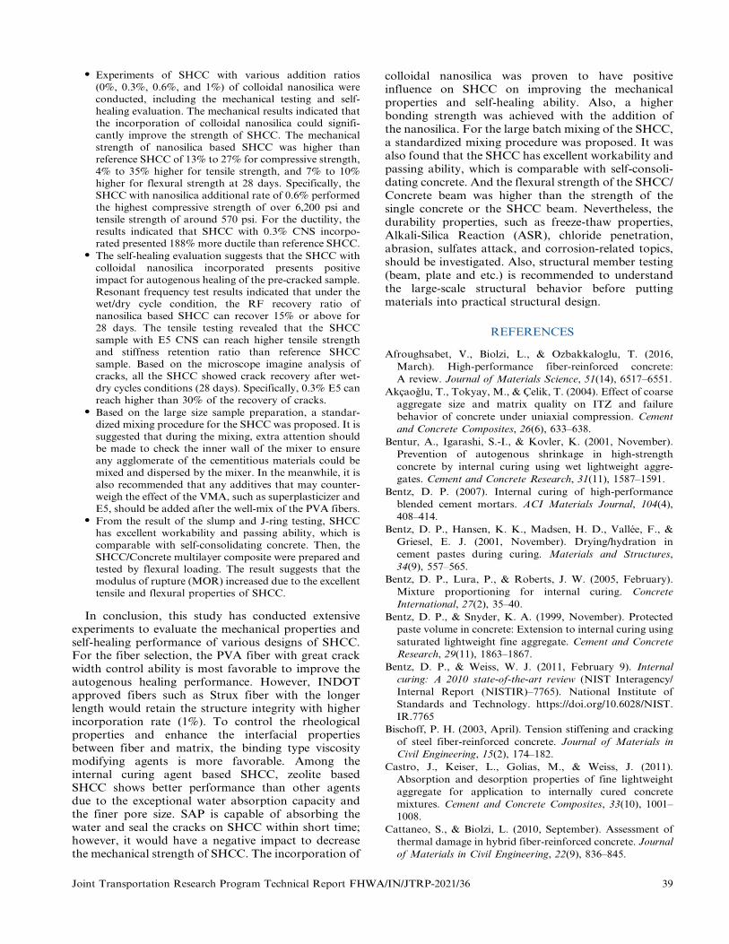
N Experiments of SHCC with various addition ratios(0%, 0.3%, 0.6%, and 1%) of colloidal nanosilica wereconducted, including the mechanical testing and self-healing evaluation. The mechanical results indicated thatthe incorporation of colloidal nanosilica could signifi-cantly improve the strength of SHCC. The mechanicalstrength of nanosilica based SHCC was higher thanreference SHCC of 13% to 27% for compressive strength,4% to 35% higher for tensile strength, and 7% to 10%
higher for flexural strength at 28 days. Specifically, theSHCC with nanosilica additional rate of 0.6% performedthe highest compressive strength of over 6,200 psi andtensile strength of around 570 psi. For the ductility, theresults indicated that SHCC with 0.3% CNS incorpo-rated presented 188% more ductile than reference SHCC.
N The self-healing evaluation suggests that the SHCC withcolloidal nanosilica incorporated presents positiveimpact for autogenous healing of the pre-cracked sample.Resonant frequency test results indicated that under thewet/dry cycle condition, the RF recovery ratio ofnanosilica based SHCC can recover 15% or above for28 days. The tensile testing revealed that the SHCCsample with E5 CNS can reach higher tensile strengthand stiffness retention ratio than reference SHCCsample. Based on the microscope imagine analysis ofcracks, all the SHCC showed crack recovery after wet-dry cycles conditions (28 days). Specifically, 0.3% E5 canreach higher than 30% of the recovery of cracks.
N Based on the large size sample preparation, a standar-dized mixing procedure for the SHCC was proposed. It issuggested that during the mixing, extra attention shouldbe made to check the inner wall of the mixer to ensureany agglomerate of the cementitious materials could bemixed and dispersed by the mixer. In the meanwhile, it isalso recommended that any additives that may counter-weigh the effect of the VMA, such as superplasticizer andE5, should be added after the well-mix of the PVA fibers.
N From the result of the slump and J-ring testing, SHCChas excellent workability and passing ability, which iscomparable with self-consolidating concrete. Then, theSHCC/Concrete multilayer composite were prepared andtested by flexural loading. The result suggests that themodulus of rupture (MOR) increased due to the excellenttensile and flexural properties of SHCC.
In conclusion, this study has conducted extensiveexperiments to evaluate the mechanical properties andself-healing performance of various designs of SHCC.For the fiber selection, the PVA fiber with great crackwidth control ability is most favorable to improve theautogenous healing performance. However, INDOTapproved fibers such as Strux fiber with the longerlength would retain the structure integrity with higherincorporation rate (1%). To control the rheologicalproperties and enhance the interfacial propertiesbetween fiber and matrix, the binding type viscositymodifying agents is more favorable. Among theinternal curing agent based SHCC, zeolite basedSHCC shows better performance than other agentsdue to the exceptional water absorption capacity andthe finer pore size. SAP is capable of absorbing thewater and seal the cracks on SHCC within short time;however, it would have a negative impact to decreasethe mechanical strength of SHCC. The incorporation of
colloidal nanosilica was proven to have positiveinfluence on SHCC on improving the mechanicalproperties and self-healing ability. Also, a higherbonding strength was achieved with the addition ofthe nanosilica. For the large batch mixing of the SHCC,a standardized mixing procedure was proposed. It wasalso found that the SHCC has excellent workability andpassing ability, which is comparable with self-consoli-dating concrete. And the flexural strength of the SHCC/Concrete beam was higher than the strength of thesingle concrete or the SHCC beam. Nevertheless, thedurability properties, such as freeze-thaw properties,Alkali-Silica Reaction (ASR), chloride penetration,abrasion, sulfates attack, and corrosion-related topics,should be investigated. Also, structural member testing(beam, plate and etc.) is recommended to understandthe large-scale structural behavior before puttingmaterials into practical structural design.
REFERENCES
Afroughsabet, V., Biolzi, L., & Ozbakkaloglu, T. (2016,
March). High-performance fiber-reinforced concrete:
A review. Journal of Materials Science, 51(14), 6517–6551.
Akcaoglu, T., Tokyay, M., & Celik, T. (2004). Effect of coarse
aggregate size and matrix quality on ITZ and failure
behavior of concrete under uniaxial compression. Cement
and Concrete Composites, 26(6), 633–638.
Bentur, A., Igarashi, S.-I., & Kovler, K. (2001, November).
Prevention of autogenous shrinkage in high-strength
concrete by internal curing using wet lightweight aggre-
gates. Cement and Concrete Research, 31(11), 1587–1591.
Bentz, D. P. (2007). Internal curing of high-performance
blended cement mortars. ACI Materials Journal, 104(4),
408–414.
Bentz, D. P., Hansen, K. K., Madsen, H. D., Vallee, F., &
Griesel, E. J. (2001, November). Drying/hydration in
cement pastes during curing. Materials and Structures,
34(9), 557–565.
Bentz, D. P., Lura, P., & Roberts, J. W. (2005, February).
Mixture proportioning for internal curing. Concrete
International, 27(2), 35–40.
Bentz, D. P., & Snyder, K. A. (1999, November). Protected
paste volume in concrete: Extension to internal curing using
saturated lightweight fine aggregate. Cement and Concrete
Research, 29(11), 1863–1867.
Bentz, D. P., & Weiss, W. J. (2011, February 9). Internal
curing: A 2010 state-of-the-art review (NIST Interagency/
Internal Report (NISTIR)–7765). National Institute of
Standards and Technology. https://doi.org/10.6028/NIST.
IR.7765
Bischoff, P. H. (2003, April). Tension stiffening and cracking
of steel fiber-reinforced concrete. Journal of Materials in
Civil Engineering, 15(2), 174–182.
Castro, J., Keiser, L., Golias, M., & Weiss, J. (2011).
Absorption and desorption properties of fine lightweight
aggregate for application to internally cured concrete
mixtures. Cement and Concrete Composites, 33(10), 1001–
1008.
Cattaneo, S., & Biolzi, L. (2010, September). Assessment of
thermal damage in hybrid fiber-reinforced concrete. Journal
of Materials in Civil Engineering, 22(9), 836–845.
Joint Transportation Research Program Technical Report FHWA/IN/JTRP-2021/36 39

Chen, W.-F., & Carson, J. L. (1971, December). Stress-strainproperties of random wire reinforced concrete. JournalProceedings, 68(12), 933–936.
Costa, H., Julio, E., & Lourenco, J. (2012, October). Newapproach for shrinkage prediction of high-strength light-weight aggregate concrete. Construction and BuildingMaterials, 35, 84–91.
Cusson, D., & Hoogeveen, T. (2007, February). An experi-mental approach for the analysis of early-age behaviour ofhigh-performance concrete structures under restrainedshrinkage. Cement and Concrete Research, 37(2), 200–209.
de la Varga, I., Castro, J., Bentz, D. P., & Weiss, J. (2012,October). Application of internal curing for mixturescontaining high volumes of fly ash. Cement and ConcreteComposites, 34(9), 1001–1008.
Ding, Y., & Kusterle, W. (2000, October). Compressive stress–strain relationship of steel fibre-reinforced concrete at earlyage. Cement and Concrete Research, 30(10), 1573–1579.
Dixit, A., Gupta, S., Pang, S. D., & Kua, H. W. (2019,November). Waste Valorisation using biochar for cementreplacement and internal curing in ultra-high performanceconcrete. Journal of Cleaner Production, 238, 117876.
Edvardsen, C. (1999, July). Water permeability and auto-genous healing of cracks in concrete. Innovation in ConcreteStructures: Design and Construction (pp. 473–487). ThomasTelford Publishing.
Eren, O., & Celik, T. (1997). Effect of silica fume and steelfibers on some properties of high-strength concrete.Construction and Building Materials, 11(7–8), 373–382.
Feng, J., Su, Y., & Qian, C. (2019, December). Coupled effectof PP fiber, PVA fiber and bacteria on self-healingefficiency of early-age cracks in concrete. Construction andBuilding Materials, 228, 116810.
Gagne, R., & Argouges, M. (2012, April). A study of thenatural self-healing of mortars using air-flow measure-ments. Materials and Structures, 45(11), 1625–1638.
Ghourchian, S., Wyrzykowski, M., Lura, P., Shekarchi, M., &Ahmadi, B. (2013, March). An investigation on the use ofzeolite aggregates for internal curing of concrete.Construction and Building Materials, 40, 135–144.
Hameed, R., Turatsinze, A., Duprat, F., & Sellier, A. (2009,July). Metallic fiber reinforced concrete: Effect of fiberaspect ratio on the flexural properties. Journal ofEngineering and Applied Sciences, 4(5), 67–72.
Hasholt, M. T., Jensen, O. M., Kovler, K., & Zhutovsky, S.(2012). Can superabsorent polymers mitigate autogenousshrinkage of internally cured concrete without compromis-ing the strength? Construction and Building Materials, 31,226–230.
Henkensiefken, R., Bentz, D., Nantung, T., & Weiss, J.(2009a, August). Volume change and cracking in internallycured mixtures made with saturated lightweight aggregateunder sealed and unsealed conditions. Cement and ConcreteComposites, 31(7), 427–437.
Henkensiefken, R., Castro, J., Bentz, D., Nantung, T., &Weiss, J. (2009b, October). Water absorption in internallycured mortar made with water-filled lightweight aggregate.Cement and Concrete Research, 39(10), 883–892.
Homma, D., Mihashi, H., & Nishiwaki, T. (2009, June).Self-healing capability of fibre reinforced cementitiouscomposites. Journal of Advanced Concrete Technology,7(2), 217–228.
Huang, H., Ye, G., Qian, C.-X., & Schlangen, E. (2016,February). Self-healing in cementitious materials:Materials, methods and service conditions. Materials andDesign, 92, 499–511.
Hung, C.-C., Su, Y.-F., & Hung, H.-H. (2017, July). Impact ofnatural weathering on medium-term self-healing perfor-mance of fiber reinforced cementitious composites withintrinsic crack-width control capability. Cement andConcrete Composites, 80, 200–209.
Hung, C.-C., Su, Y.-F., & Su, Y.-M. (2018). Mechanicalproperties and self-healing evaluation of strain-hardeningcementitious composites with high volumes of hybridpozzolan materials. Composites Part B: Engineering, 133,15–25.
Jacobsen, S., Marchand, J., & Hornain, H. (1995, December).SEM observations of the microstructure of frost deterio-rated and self-healed concretes. Cement and ConcreteResearch, 25(8), 1781–1790.
Jensen, O. M., & Hansen, P. F. (2001, April). Water-entrainedcement-based materials: I. Principles and theoretical back-ground. Cement and Concrete Research, 31(4), 647–654.
Jensen, O. M., & Hansen, P. F. (2002, June). Water-entrainedcement-based materials: II. Experimental observations.Cement and Concrete Research, 32(6), 973–978.
Jiang, Z., Li, W., & Yuan, Z. (2015, March). Influence ofmineral additives and environmental conditions on theself-healing capabilities of cementitious materials. Cementand Concrete Composites, 57, 116–127.
Justs, J., Wyrzykowski, M., Bajare, D., & Lura, P. (2015,October). Internal curing by superabsorbent polymers inultra-high performance concrete. Cement and ConcreteResearch, 76, 82–90.
Kang, S.-H., Hong, S.-G., & Moon, J. (2018, April).Importance of monovalent ions on water retention capacityof superabsorbent polymer in cement-based solutions.Cement and Concrete Composites, 88, 64–72.
Kaufmann, W., Amin, A., Beck, A., & Lee, M. (2019, May).Shear transfer across cracks in steel fibre reinforcedconcrete. Engineering Structures, 186, 508–524.
Keskin, S., Keskin, O. K., Anil, O., Sahmaran, M., Alyousif,A., Lachemi, M., Amleh, L., & Ashour, A. (2016,September). Self-healing capability of large-scale engineeredcementitious composites beams. Composites Part B:Engineering, 101, 1–13.
Kjeldsen, A. M., Flatt, R. J., & Bergstrom, L. (2006, July).Relating the molecular structure of comb-type super-plasticizers to the compression rheology of MgO suspen-sions. Cement and Concrete Research, 36(7), 1231–1239.
Koksal, F., Altun, F., Yigit, I., & Sahin, Y. (2008, August).Combined effect of silica fume and steel fiber on themechanical properties of high strength concretes.Construction and Building Materials, 22(8), 1874–1880.
Kong, X., Zhang, Z.-L., & Lu, Z.-C. (2015). Effect ofpre-soaked superabsorbent polymer on shrinkage ofhigh-strength concrete. Materials and Structures, 48(9),2741–2758.
Kou, S. C., Poon, C. S., & Etxeberria, M. (2014, October).Residue strength, water absorption and pore size distribu-tions of recycled aggregate concrete after exposure toelevated temperatures. Cement and Concrete Composites,53, 73–82.
Kuder, K. G., & Shah, S. P. (2010, February). Processing ofhigh-performance fiber-reinforced cement-based compo-sites. Construction and Building Materials, 24(2), 181–186.
Lau, A., & Anson, M. (2006, September). Effect of hightemperatures on high performance steel fibre reinforcedconcrete. Cement and Concrete Research, 36(9), 1698–1707.
Lee, H. X. D., Wong, H. S., & Buenfeld, N. R. (2018,April). Effect of alkalinity and calcium concentration ofpore solution on the swelling and ionic exchange of
40 Joint Transportation Research Program Technical Report FHWA/IN/JTRP-2021/36

superabsorbent polymers in cement paste. Cement andConcrete Composites, 88, 150–164.
Ma, H., Qian, S., & Zhang, Z. (2014, October). Effect of self-healing on water permeability and mechanical property ofmedium-early-strength engineered cementitious composites.Construction and Building Materials, 68, 92–101.
Ma, X., Liu, J., & Shi, C. (2019). A review on the use of LWAas an internal curing agent of high performance cement-based materials. Construction and Building Materials, 218,385–393.
Marar, K., Eren, O., & Celik, T. (2001, February).Relationship between impact energy and compressiontoughness energy of high-strength fiber-reinforced concrete.Materials Letters, 47(4–5), 297–304.
Masum, A. T. M., & Manzur, T. (2019, December). Delayingtime to corrosion initiation in concrete using brickaggregate as internal curing medium under adverse curingconditions. Construction and Building Materials, 228,116772.
Mechtcherine, V., Dudziak, L., Schulze, J., & Staehr, H.(2006, January). Internal curing by super absorbentpolymers (SAP)–Effects on material properties of self-compacting fibre-reinforced high performance concrete.Proceedings of the International RILEM Conference—Volume Changes of Hardening Concrete: Testing andMitigation (pp. 87–96).
Mechtcherine, V., Gorges, M., Schroefl, C., Assmann, A.,Brameshuber, W., Ribeiro, A. B., Cusson, D., Custodio, J.,da Silva, E. F., Ichimiya, K., Igarashi, S.-I., Klemm, A.,Kovler, K., de Mendonca Lopes, A. N., Lura, P., Nguyen,V. T., Reinhardt, H.-W., Filho, R. D. T., Weiss, J. . . .Zhutovsky, S. (2014). Effect of internal curing by usingsuperabsorbent polymers (SAP) on autogenous shrinkageand other properties of a high-performance fine-grainedconcrete: Results of a RILEM round-robin test. Materialsand Structures, 47(3), 541–562.
Mechtcherine, V., Snoeck, D., Schrofl, C., De Belie, N.,Klemm, A. J., Ichimiya, K., Moon, J., Wyrzykowski, M.,Lura, P., Toropovs, N., Assmann, A., Igarashi, S.-I., De LaVarga, I., Almeida, F. C. R., Erk, K., Ribeiro, A. B.,Custodio, J., Reinhardt, H. W., & Falikman, V. (2018).Testing superabsorbent polymer (SAP) sorption propertiesprior to implementation in concrete: results of a RILEMRound-Robin Test. Materials and Structures, 51(28), 1–16.
Mihashi, H., & Nishiwaki, T. (2012, May). Development ofengineered self-healing and self-repairing concrete-state-of-the-art report. Journal of Advanced Concrete Technology,10(5), 170–184.
Nishiwaki, T., Koda, M., Yamada, M., Mihashi, H., &Kikuta, T. (2012). Experimental study on self-healingcapability of FRCC using different types of synthetic fibers.Journal of Advanced Concrete Technology, 10(6), 195–206.
Noushini, A., Samali, B., & Vessalas, K. (2013, December).Effect of polyvinyl alcohol (PVA) fibre on dynamicand material properties of fibre reinforced concrete.Construction and Building Materials, 49, 374–383. https://doi.org/10.1016/j.conbuildmat.2013.08.035
Paipetis, A., Galiotis, C., Liu, Y. C., & Nairn, J. A. (1999,February). Stress transfer from the matrix to the fibre in afragmentation test: Raman experiments and analyticalmodeling. Journal of Composite Materials, 33(4), 377–399.
Paul, A., & Lopez, M. (2011, July). Assessing lightweightaggregate efficiency for maximizing internal curing perfor-mance. ACI Materials Journal, 108(4), 385–393.
Qian, S. Z., Zhou, J., & Schlangen, E. (2010, October).Influence of curing condition and precracking time on the
self-healing behavior of engineered cementitious compo-sites. Cement and Concrete Composites, 32(9), 686–693.
Ranade, R., Stults, M. D., Li, V. C., Rushing, T. S., Roth, J.,& Heard, W. F. (2011, December 12–14). Development ofhigh strength high ductility concrete. 2nd InternationalRILEM Conference on Strain Hardening CementitiousComposites, Rio de Janeiro, Brazil.
Roig-Flores, M., Pirritano, F., Serna Ros, P., & Ferrara, L.(2016, July). Effect of crystalline admixtures on the self-healing capability of early-age concrete studied by means ofpermeability and crack closing tests. Construction andBuilding Materials, 114, 447–457. https://doi.org/10.1016/j.conbuildmat.2016.03.196
Sahmaran, M., Lachemi, M., Hossain, K. M., & Li, V. C.(2009, October). Internal curing of engineered cementitiouscomposites for prevention of early age autogenous shrink-age cracking. Cement and Concrete Research, 39(10), 893–901.
Sisomphon, K., Copuroglu, O., & Koenders, E. A. B. (2013,May). Effect of exposure conditions on self healingbehavior of strain hardening cementitious compositesincorporating various cementitious materials. Constructionand Building Materials, 42, 217–224.
Snoeck, D. (2015). Self-healing and microstructure of cementi-tious materials with microfibres and superabsorbent polymers[Doctoral dissertation, Ghent University]. http://hdl.handle.net/1854/LU-7010896
Su, Y.-F., Huang, C., Jeong, H., Nantung, T., Olek, J., Baah,P., & Lu, N. (2020). Autogenous healing performance ofinternal curing agent-based self-healing cementitious com-posite. Cement and Concrete Composites, 114, 103825.
Subcommittee C09.64. (2019). Standard test method forfundamental transverse, longitudinal, and torsional resonantfrequencies of concrete specimens (ASTM C215–19). ASTMInternational. http://www.astm.org/cgi-bin/resolver.cgi?C215-19
Termkhajornkit, P., Nawa, T., Yamashiro, Y., & Saito, T.(2009, March). Self-healing ability of fly ash–cementsystems. Cement and Concrete Composites, 31(3), 195–203.
Tu, W., Zhu, Y., Fang, G., Wang, X., & Zhang, M. (2018).Internal curing of alkali-activated fly ash-slag pastes usingsuperabsorbent polymer. Cement and Concrete Research,116, 179–190.
Van Tittelboom, K., & De Belie, N. (2013). Self-healing incementitious materials—A review. Materials, 6, 2182–2217.
Van, V.-T.-A., Roßler, C., Bui, D.-D., & Ludwig, H.-M.(2014, July). Rice husk ash as both pozzolanic admixtureand internal curing agent in ultra-high performanceconcrete. Cement and Concrete Composites, 53, 270–278.
Yang, Y., Lepech, M. D., Yang, E.-H., & Li, V. C. (2009,May). Autogenous healing of engineered cementitiouscomposites under wet–dry cycles. Cement and ConcreteResearch, 39(5), 382–390.
Yıldırım, G., Keskin, O. K., Keskin, S. B., Sahmaran, M., &Lachemi, M. (2015). A review of intrinsic self-healingcapability of engineered cementitious composites: Recoveryof transport and mechanical properties. Construction andBuilding Materials, 101(Part 1), 10–21.
Yoo, D.-Y., Kang, S.-T., & Yoon, Y.-S. (2014, August).Effect of fiber length and placement method on flexuralbehavior, tension-softening curve, and fiber distributioncharacteristics of UHPFRC. Construction and BuildingMaterials, 64, 67–81.
Yoo, D.-Y., Zi, G., Kang, S.-T., & Yoon, Y.-S. (2015,October). Biaxial flexural behavior of ultra-high-perfor-mance fiber-reinforced concrete with different fiber lengths
Joint Transportation Research Program Technical Report FHWA/IN/JTRP-2021/36 41

and placement methods. Cement and Concrete Composites,63, 51–66.
Zhang, J., Wang, Q., & Zhang, J. (2017, March). Shrinkage ofinternal cured high strength engineered cementitiouscomposite with pre-wetted sand-like zeolite. Constructionand Building Materials, 134, 664–672.
Zhang, J., Zheng, X., & Wang, Q. (2018). Mixture optimiza-tion on internally cured high strength engineered cementi-tious composite with pre-wetted sand-like Zeolite. Journalof Advanced Concrete Technology, 16(9), 485–497.
Zhang, Z., Qian, S., & Ma, H. (2014, February). Investigating
mechanical properties and self-healing behavior of micro-
cracked ECC with different volume of fly ash. Construction
and Building Materials, 52, 17–23.
Zhu, Q., Barney, C. W., & Erk, K. A. (2015). Effect of
ionic crosslinking on the swelling and mechanical
response of model superabsorbent polymer hydrogels for
internally cured concrete. Materials and Structures, 48(7),
2261–2276.
42 Joint Transportation Research Program Technical Report FHWA/IN/JTRP-2021/36
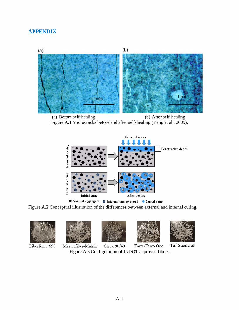
APPENDIX
(a) Before self-healing (b) After self-healing Figure A.1 Microcracks before and after self-healing (Yang et al., 2009).
Figure A.2 Conceptual illustration of the differences between external and internal curing.
Figure A.3 Configuration of INDOT approved fibers.
A-1

Figure A.4 Test setup for the flexural test.
Figure A.5 Test setup for the uniaxial tensile test.
Figure A.6 Particle size distribution of zeolite and silica sand.
A-2

Piezoelectric Vibration Detector
Hit point Oscilloscope
Sponge support
Figure A.7 Setup of resonant frequency test.
Figure A.8 Setup of ultrasonic velocity test.
Figure A.9 Experimental setup for filtration test.
A-3

Figure A.10 Experimental setup for water flow test.
Figure A.11 Particle size distributions of the SAP and cement.
A-4

Figure A.12 Absorption behavior of the SAPs in DI water and synthetic cement pore solution.
Figure A.13 Results of flexural strength with various configuration of VMA-SHCC with PVA fiber.
A-5

Figure A.14 Results of flexural strength with various configurations of VMA-SHCC with Strux fiber.
Figure A.15 Ductility index of PVA-SHCC with the various dosage of VMA 450.
A-6

(a) Reference SHCC (b) 0.3%E5 SHCC
(c) 0.6 % E5 SHCC (d) 1% E5 SHCC Figure A.16 Representative SEM images for SHCC specimens (after 21 W/D cycles).
Figure A.17 SHCC sample and flexural testing.
A-7

Table A.1 Material properties of the fibers
Specific Length Tensile Strength Fiber Name Gravity (In) (MPA) Aspect Ratio PVA 1.3 0.3 1,600 205 Strux 90/40 0.92 1.55 620 90 Masterfiber Mac 0.91 2.1 585 70 Matrix Fiberforce 650 0.91 1.5 – 100Tuf-Strand SF 0.92 2 625 74Forta-Ferro One 0.91 2.25 615 –
Table A.2 Design of different layer structure of SHCC/Concrete beam
Layer Structure SHCC Layer (%) Configuration SHCC 100% (SHCC Reference) SHCC-4″ SHCC 75% Concrete-1″/SHCC-3″ SHCC 50% Concrete-2″/SHCC-2″ SHCC 25% Concrete-3″/SHCC-1″ SHCC 0% (Concrete Reference) Concrete-4″
Table A.3 Unit price of raw materials
Type I Natural Fly Granulated Silica Silica Cement Sand Stone Ash Slag Sand Fume PVA Steel Fiber
Unit ~128 ~17.5 ~21.5 15~40 35–70 50–300 400–1,000 ~17,085 2,800–13,300 price ($/ton)
Note: Table sources: The Aberdeen Group, 1985; Alibaba.com, n.d.; Clayworks Supplies, Inc., n.d.; Condensed silica fume, n.d.; FHWA, 2013; HomeAdvisor, n.d.; NYCON, n.d.; Van Oss, 2002; Reference.com, 2020; Statista, n.d.
Table A.4 Mixture designs of different types of concrete materials
Cement Natural Sand Stone Fly Ash Silica Sand Silica Fume Fiber (lb/cyd) (lb/cyd) (lb/cyd) (lb/cyd) (lb/cyd) (lb/cyd) (vol%)
INDOT-564 (w/c = 0.42) 564 1,344 1800 – – – – SHCC (w/c = 0.35) 1,241 993 – 620 – – 1 ECC (w/c = 0.30) 947 – – 1,136 756 – 2UHPC (w/c = 0.18) 1,718 – – – 1,306 447 2.5
A-8
APPENDIX REFERENCES
The Aberdeen Group. (1985). Fly ash [PDF file]. https://www.concreteconstruction.net/_view-object?id=00000153-8b9c-dbf3-a177-9fbd58630000
Alibaba.com. (n.d.). Silica sand price per ton [Webpage]. https://www.alibaba.com/showroom/silica-sand-price-per-ton.html
Clayworks Supplies, Inc. (n.d.). Silica sand bulk pricing–50 lb. bag [Webpage]. https://clayworkssupplies.com/product/silica-sand-bulk-pricing/
Condensed silica fume. (n.d.). https://www.engr.psu.edu/ce/courses/ce584/concrete/library/materials/Altmaterials/Silica%2 0Fume.htm
FHWA. (2013, October). Development of non-proprietary ultra-high performance concrete for use in the highway bridge sector (Report Publication No. FHWA-HRT-13-100). Federal Highway Administration. https://www.fhwa.dot.gov/publications/research/infrastructure/structures/bridge/13100/inde x.cfm
HomeAdvisor. (n.d.). How much does it cost to deliver topsoil, dirt, sand, mulch, or rock? [Webpage]. https://www.homeadvisor.com/cost/landscape/deliver-soil-mulch-or-rocks/
NYCON. (n.d.). RMS702 [Webpage]. https://nycon.com/products/rms702
Reference.com. (2020, April 9). How much does silica sand cost? https://www.reference.com/science/much-silica-sand-cost-d092088142328ed7
Statista. (n.d.) Cement prices in the United States from 2010 to 2021 [Webpage]. https://www.statista.com/statistics/219339/us-prices-of-cement/
Van Oss, H. G. (2002). Slag—Iron and steel [PDF file]. U.S. Geological Survey Minerals Yearbook. https://s3-us-west-2.amazonaws.com/prd-wret/assets/palladium/production/mineral-pubs/iron-steel-slag/islagmyb02.pdf
A-9

About the Joint Transportation Research Program (JTRP) On March 11, 1937, the Indiana Legislature passed an act which authorized the Indiana State Highway Commission to cooperate with and assist Purdue University in developing the best methods of improving and maintaining the highways of the state and the respective counties thereof. That collaborative effort was called the Joint Highway Research Project (JHRP). In 1997 the collaborative venture was renamed as the Joint Transportation Research Program (JTRP) to reflect the state and national efforts to integrate the management and operation of various transportation modes.
The first studies of JHRP were concerned with Test Road No. 1 — evaluation of the weathering characteristics of stabilized materials. After World War II, the JHRP program grew substantially and was regularly producing technical reports. Over 1,600 technical reports are now available, published as part of the JHRP and subsequently JTRP collaborative venture between Purdue University and what is now the Indiana Department of Transportation.
Free online access to all reports is provided through a unique collaboration between JTRP and Purdue Libraries. These are available at http://docs.lib.purdue.edu/jtrp.
Further information about JTRP and its current research program is available at http://www.purdue.edu/jtrp.
About This Report An open access version of this publication is available online. See the URL in the citation below.
Huang, C., Su, Y.-F., & Lu, N. (2021). Self-healing cementitious composites (SHCC) with ultrahigh ductility for pavement and bridge construction (Joint Transportation Research Program Pub-lication No. FHWA/IN/JTRP-2021/36). West Lafayette, IN: Purdue University. https://doi. org/10.5703/1288284317403
Copyright © 2022 FDOKUMEN