Efficiency of RC square columns repaired with polymer-modified cementitious mortars
11
Efficiency of RC square columns repaired with polymer-modified cementitious mortars Francesca da Porto ⇑ , Elena Stievanin, Carlo Pellegrino Department of Structural and Transportation Engineering, University of Padova, Via Marzolo 9, 35131 Padova, Italy article info Article history: Received 23 October 2010 Received in revised form 27 November 2011 Accepted 28 November 2011 Available online 20 December 2011 Keywords: Reinforced concrete Repair mortar Elastic modulus Compressive strength Columns abstract This paper regards the axial behavior of reinforced concrete columns repaired by polymer-modified cemen- titious mortars. Tests were performed on eight columns with square cross-section: six were repaired with three types of polymer-modified cementitious mortars on all faces, two were in non-damaged and non- repaired condition (control elements). Tests were repeated varying mechanical properties (elastic modulus and compressive strength) of repair materials, maintaining the same repair thickness, including the rein- forcement bars. Comparisons between repaired and control elements showed that polymer-modified cementitious mortars cannot restore the original load-bearing capacity of columns. In spite of this, selection of mortar mechanical properties plays a significant role. Among the three types of repair mortar tested in this experimental study, using the material with the most similar elastic modulus and higher compressive strength than that of the concrete substrate is recommended. Ó 2011 Elsevier Ltd. All rights reserved. 1. Introduction Reinforced concrete often shows its vulnerability to time depen- dent phenomena, including weathering, well before reaching the intended service life of the structure. The phenomenon is so wide- spread that systematic replacement of existing structures is not a possible measure. Thus, interest in rehabilitation and strengthening of reinforced concrete structural elements has been rapidly increas- ing around the world in the past two decades. Various research pro- grams were aimed at developing materials and methods for improving the safety and reliability of existing concrete structures. In this framework, externally bonded fiber reinforced polymers (FRPs) sheets/plates have several attractive properties, such as low weight-to-strength ratios, non-corrosiveness, and ease of application. A number of experimental and analytical studies have already been carried out at the University of Padova on flexural [1], shear [2] and bond behavior [3] of FRP strengthened elements. Add- ing or applying mortar, or spraying concrete or mortar with the aim of rehabilitating and/or strengthening of existing reinforced con- crete structures are also possible ways of intervening with a more traditional and common material. Emberson and Mays [4] discussed the mechanical and physical properties of mortar repair systems and created two- and three- dimensional linear elastic finite element models to reproduce axial load transfer through simple patch repairs in reinforced concrete members. They also worked on reinforced concrete beams in flexure and studied the effect of repairs in both compression and tension zones [5]. Pellegrino et al. [6] investigated the efficiency of rehabilitation interventions on reinforced concrete columns with polymer-modified cementitious mortar. Axially loaded ele- ments were tested by varying repair thickness, which included or did not include reinforcement bars. The mortar was applied on one face only of square columns. The authors found that the repair could not restore the same load-bearing capacity as non-damaged control columns. However, if repairs include longitudinal rein- forcement bars, the repaired element shows stable behavior, shar- ing of loads and plasticization of the material before failure. The same authors also studied the effect of repairs in both compression and tension zones, and including or not reinforcement bars, on reinforced concrete beams in flexure [7]. Mangat and O’Flaherty [8] studied the influence of elastic modulus on stress redistribution and cracking in repair patches for axially loaded elements. Results showed that repairs applied with relatively stiff materials display efficient structural interac- tion with the structure. High stiffness repairs are effective in redistributing shrinkage strain to the substrate and attracting external loads in the long term. Low stiffness repair materials are much more likely to undergo tensile cracking due to re- strained shrinkage, and are ineffective in redistributing strain. Sharif et al. [9] conducted an experimental investigation to assess the effectiveness of patch repairs in axially loaded columns. The load distribution between patch repair, concrete core and steel reinforcement depended on the modulus of elasticity and areas of these components in the composite repaired section. In order for patch repair to be structurally effective, the loads before 0958-9465/$ - see front matter Ó 2011 Elsevier Ltd. All rights reserved. doi:10.1016/j.cemconcomp.2011.11.020 ⇑ Corresponding author. Tel./fax: +39 049 8275631. E-mail address: [email protected] (F. da Porto). Cement & Concrete Composites 34 (2012) 545–555 Contents lists available at SciVerse ScienceDirect Cement & Concrete Composites journal homepage: www.elsevier.com/locate/cemconcomp
Transcript of Efficiency of RC square columns repaired with polymer-modified cementitious mortars

Cement & Concrete Composites 34 (2012) 545–555
Contents lists available at SciVerse ScienceDirect
Cement & Concrete Composites
journal homepage: www.elsevier .com/locate /cemconcomp
Efficiency of RC square columns repaired with polymer-modifiedcementitious mortars
Francesca da Porto ⇑, Elena Stievanin, Carlo PellegrinoDepartment of Structural and Transportation Engineering, University of Padova, Via Marzolo 9, 35131 Padova, Italy
a r t i c l e i n f o a b s t r a c t
Article history:Received 23 October 2010Received in revised form 27 November 2011Accepted 28 November 2011Available online 20 December 2011
Keywords:Reinforced concreteRepair mortarElastic modulusCompressive strengthColumns
0958-9465/$ - see front matter � 2011 Elsevier Ltd. Adoi:10.1016/j.cemconcomp.2011.11.020
⇑ Corresponding author. Tel./fax: +39 049 8275631E-mail address: [email protected] (F. da Porto).
This paper regards the axial behavior of reinforced concrete columns repaired by polymer-modified cemen-titious mortars. Tests were performed on eight columns with square cross-section: six were repaired withthree types of polymer-modified cementitious mortars on all faces, two were in non-damaged and non-repaired condition (control elements). Tests were repeated varying mechanical properties (elastic modulusand compressive strength) of repair materials, maintaining the same repair thickness, including the rein-forcement bars. Comparisons between repaired and control elements showed that polymer-modifiedcementitious mortars cannot restore the original load-bearing capacity of columns. In spite of this, selectionof mortar mechanical properties plays a significant role. Among the three types of repair mortar tested inthis experimental study, using the material with the most similar elastic modulus and higher compressivestrength than that of the concrete substrate is recommended.
� 2011 Elsevier Ltd. All rights reserved.
1. Introduction
Reinforced concrete often shows its vulnerability to time depen-dent phenomena, including weathering, well before reaching theintended service life of the structure. The phenomenon is so wide-spread that systematic replacement of existing structures is not apossible measure. Thus, interest in rehabilitation and strengtheningof reinforced concrete structural elements has been rapidly increas-ing around the world in the past two decades. Various research pro-grams were aimed at developing materials and methods forimproving the safety and reliability of existing concrete structures.In this framework, externally bonded fiber reinforced polymers(FRPs) sheets/plates have several attractive properties, such aslow weight-to-strength ratios, non-corrosiveness, and ease ofapplication. A number of experimental and analytical studies havealready been carried out at the University of Padova on flexural [1],shear [2] and bond behavior [3] of FRP strengthened elements. Add-ing or applying mortar, or spraying concrete or mortar with the aimof rehabilitating and/or strengthening of existing reinforced con-crete structures are also possible ways of intervening with a moretraditional and common material.
Emberson and Mays [4] discussed the mechanical and physicalproperties of mortar repair systems and created two- and three-dimensional linear elastic finite element models to reproduce axialload transfer through simple patch repairs in reinforced concretemembers. They also worked on reinforced concrete beams in
ll rights reserved.
.
flexure and studied the effect of repairs in both compression andtension zones [5]. Pellegrino et al. [6] investigated the efficiencyof rehabilitation interventions on reinforced concrete columnswith polymer-modified cementitious mortar. Axially loaded ele-ments were tested by varying repair thickness, which included ordid not include reinforcement bars. The mortar was applied onone face only of square columns. The authors found that the repaircould not restore the same load-bearing capacity as non-damagedcontrol columns. However, if repairs include longitudinal rein-forcement bars, the repaired element shows stable behavior, shar-ing of loads and plasticization of the material before failure. Thesame authors also studied the effect of repairs in both compressionand tension zones, and including or not reinforcement bars, onreinforced concrete beams in flexure [7].
Mangat and O’Flaherty [8] studied the influence of elasticmodulus on stress redistribution and cracking in repair patchesfor axially loaded elements. Results showed that repairs appliedwith relatively stiff materials display efficient structural interac-tion with the structure. High stiffness repairs are effective inredistributing shrinkage strain to the substrate and attractingexternal loads in the long term. Low stiffness repair materialsare much more likely to undergo tensile cracking due to re-strained shrinkage, and are ineffective in redistributing strain.Sharif et al. [9] conducted an experimental investigation to assessthe effectiveness of patch repairs in axially loaded columns. Theload distribution between patch repair, concrete core and steelreinforcement depended on the modulus of elasticity and areasof these components in the composite repaired section. In orderfor patch repair to be structurally effective, the loads before

Table 1Details of specimens.
Type and no. of elements Condition Designation Section (mm2) Longitudinalreinforcement
ql (%) Transversereinforcement
qw (%)
2 Columns Control P0_1; P0_2 300 � 300 4ø12 0.50 1ø8/140 mm 0.242 Columns Repair a P50_a1; P50_a22 Columns Repair b P50_b1; P50_b22 Columns Repair ab P50_ab1; P50_ab2
Fig. 1. Dimensions, bars and repairs: control column (left) and repaired column (right).
Table 2Mechanical, physical and chemical properties of materials.
Property Concrete C42/50 Mortar type a Mortar type b Mortar type ab
Mean tensile strength (N/mm2) [15] 3.35 3.96 4.78 4.52Mean flexural strength (N/mm2) [16,17] – 6.79 8.20 7.76Mean cubic compressive strength (N/mm2) [16,17] 50.83 60.92 (+20%) 44.40 (�12%) 55.15 (+9%)Mean elastic modulus (N/mm2) [18] 31,350 29,210 (�7%) 25,540 (�19%) 28,180 (�10%)Granulometry (mm) [19] – 0.00–4.00Water content (l/kg) – 0.17Degradability to sulfates [20] – AbsentDensity (kN/m3) [21] – 20.00Diffusion resistance of CO2 [22] – l > 190Diffusion resistance of vapor – l > 60pH – >12
546 F. da Porto et al. / Cement & Concrete Composites 34 (2012) 545–555
undertaking the intervention must, when possible, be relieve,either partially or totally,
A number of works have also focused on bonds between con-crete and repair materials. Tokushige et al. [10] experimentallyand analytically estimated the deformation of concrete membersoverlaid with unsaturated polyester polymer mortars. They alsoevaluated peeling and shearing stresses at the interface betweenconcrete and polymer mortar. Courard [11] analyzed the factorsaffecting the repair system/concrete support interface, and pro-posed a sequential flow sheet related to these parameters. Kamadaand Li [12] presented the influence of surface preparation on thekink-crack trapping mechanism of engineered cementitious com-posites for concrete repair. In their experiments, the ‘‘smooth sur-face’’ showed more desirable behavior in terms of crack patternand crack widths than the ‘‘rough surface’’ system. Garbacz et al.[13] studied the effect of various surface treatments (grinding,sandblasting, shot blasting, hand and mechanical milling) on inter-ventions, on the basis of three main parameters: surface geometry,superficial concrete micro cracking, and adhesion. Yubin et al. [14]
tested a method for controlling shrinkage cracking in repaired con-crete structures, based on an intermediate layer of carbon fiberreinforced cement mortar.
Although the application of mortar around the entire perimeterof axially loaded elements is a quite common rehabilitation inter-vention in practice, its efficiency has not yet been studied from theexperimental point of view. Hence, the aim of this study is to givesome new insights on the effect of repair mortar properties on thestructural behavior of square columns repaired on four sides. Start-ing from the results obtained by Pellegrino et al. [6], who testedcolumns repaired on one side only and with one mortar type only,an experimental study on eight axially loaded square columns wascarried out. In this study, three polymer-modified cementitiousmortars for repair, having different elastic moduli and compressivestrengths, were applied over the entire perimeter of six columns.The repair was sufficiently thick to include longitudinal and trans-verse reinforcement bars. Two columns, named control elements,were prepared and tested in non-damaged and non-repairedcondition.

F. da Porto et al. / Cement & Concrete Composites 34 (2012) 545–555 547
2. Specimens and testing procedures
Column dimensions and repair thickness were selected to com-pare the test results with those obtained in the previous experi-mental research [6]. Columns were made with a square sectionarea of 300 � 300 mm, having 50 mm of repair mortar applied inmore than one layer, and a total height of 800 mm. Longitudinalreinforcement involved four 12-mm diameter reinforcing bars.Stirrups were made of 8-mm diameter reinforcing bars, placed at140-mm spacing. The columns were cast leaving the reinforcementuncovered, with a curing process of 28 days. After this period, theuncovered surface was prepared to improve the adhesion betweenconcrete substrate and mortar. The preparation of the surface in-cluded roughening, cleaning of dust and powders, and wetting.After evaporation of any water in excess, the polymer-modifiedcementitious mortar was applied. Repair mortar was 50 mm thickand included reinforcement bars in all columns, as the previousexperimental study had shown this condition develops betterbehavior than repairs that substitute the concrete cover only. Table1 lists the details of tested columns, and Fig. 1 shows the geometryof elements.
2.1. Materials
The main mechanical properties of concrete were experimen-tally assessed after 28 days of curing. Eight cubic specimens of
Fig. 2. Test set-up and instrum
150 � 150 � 150 mm, cast during column construction, had anaverage compressive strength of 50.83 N/mm2. Mean tensilestrength, measured by splitting tests on seven cylindrical sampleshaving 155-mm diameter and 300-mm height, was 3.34 N/mm2.Elastic modulus was measured on cylindrical samples (height300 mm, diameter 150 mm) and the average value was 31,530 N/mm2.
Ribbed bars used for longitudinal reinforcement and transversereinforcement were both tested in tension. The yield stress of thereinforcing bars was on average 594 N/mm2, and the ultimatestrength was 660 N/mm2 .
The repair materials used in these tests were of three types. Allwere thixotropic, polymer-modified mortars with high-strengthhydraulic binders and aggregates having a maximum thickness of4 mm. These products have high bond properties, low CO2 and va-por permeability, and limited shrinkage. Elastic modulus and com-pressive strength were the two parameters chosen to distinguishthe three types of mortars (a, b, ab) and the corresponding typesof repaired columns (P50_a, P50_b, P50_ab).
The mechanical properties of repair mortars were measured onspecimens having dimensions of 40 � 40 � 160 mm, cast duringthe repair interventions on columns. Their mechanical, physicaland chemical properties are listed in Table 2, which also comparesthe mechanical properties of repair materials and concrete sub-strate. The experimental program was planned to obtain variousratios of the mechanical properties of concrete core and repair
entation for axial tests.

548 F. da Porto et al. / Cement & Concrete Composites 34 (2012) 545–555
materials. Type a mortar had an elastic modulus slightly lowerthan that of the concrete substrate (�7%) and higher compressivestrength (+20%); type b mortar had both mechanical propertieslower than those of concrete (elastic modulus �12%, compressivestrength �19%), and type ab mortar had elastic modulus slightlylower (�10%) and compressive strength slightly higher (+9%) thanthose of the concrete substrate (Table 2).
2.2. Loading and measurement
The reinforced concrete columns were loaded monotonicallyunder a 10,000 kN loading machine, in control displacement (1/400 mm/s). The same type and same number of instruments wereplaced in both control and repaired columns.
Eight displacement transducers, with a variable measuringbase, were vertically (SV1 to SV4) and horizontally (SH1 to SH4)installed on all column external faces to measure the overall axialand transverse strains of columns. Six strain transducers (DD1;100 mm measuring base) were also placed horizontally on twoadjacent faces (three on each side), to measure transverse strains.Fig. 2 shows the test set-up and instrumentation on the four col-umn sides. In addition, before the concrete was cast, four strain-gauges were installed on the longitudinal bars and four on thestirrups, at mid-height along the columns (Fig. 3), for informationon strains on the longitudinal and transversal reinforcement bars.
Fig. 3. Strain-gauges on stirrups and longitudinal reinforcement bars.
3. Test results
3.1. Failure modes
The test results indicated that all columns exhibited typicalcompressive failure, with crushing of concrete and mortar. Verticalcracks generally developed close to the column top and bottom,where damage was concentrated. Differences in failure modesand crack distribution were caused by the various repair materialsapplied. Figs. 4–7 show crack patterns of the tested columns.
In control columns P0_1 and P0_2, failure occurred by crushingof concrete mostly at the upper ends of columns (Fig. 4). Crackswere vertical and distributed on the four column sides, mainlyclose to the corners.
Columns P50_a1 and P50_a2 (Fig. 5) were repaired on all foursides with 50 mm thick mortar layer of type a. Failure was quitesimilar to that of columns P0, with crack uniformly distributedon the four sides, and close to the corners. Some portions of repairwere detached from the elements only after ultimate load (Fig. 4and 6).
Columns P50_b1 and P50_b2 were repaired on all four sideswith 50-mm thick mortar layer of type b. Cracks had vertical andhorizontal patterns at failure, and were especially concentratedat the upper ends of elements. A limited number of cracks devel-oped in P50_b2. Conversely, P50_b1 presented the highest numberof vertical cracks along all the faces, and horizontal cracks mainlylocated at mid-height. In the most damaged areas, various layersof mortars, corresponding to different application phases, wereprogressively detached one from the other (Fig. 6).
Columns P50_ab1 and P50_ab2 were repaired on all four sideswith 50-mm thick mortar layer of type ab. Compared with col-umns P50_a and P50_b, the crack pattern had intermediate fea-tures, and was distributed on the four column sides. Cracksdeveloped from the beginning of the loading phase and were lo-cated both close to column ends and in the middle of the element,with a uniform pattern. Also in this case some phenomena of re-pair mortar layer detachment, similar to that of columns P50_b,occurred (Fig. 7).
3.2. Stresses and strains
Table 3 lists the compressive test results of the eight concretecolumns. Stress values at ultimate load for P0_1 and P0_2 were25.55 N/mm2 and 28.49 N/mm2. The value assumed for the controlcolumns was the average of the two, i.e., 27.00 N/mm2. The averagemaximum stress of P50_a columns was 25.36 N/mm2, which isabout 95% of the average maximum stress of control columns;the maximum stress of P50_b and P50_ab columns was between85% and 86% of that of control columns. These results indicate thatmortar a, with its higher compressive strength, allowed the col-umns to bear higher loads and to withstand lower crushing. Interms of load, type b mortar showed the worst behavior, due toits lower elastic modulus and compressive strength. Indeed, mortarab gave slightly higher values of ultimate load than mortar b,thanks to its intermediate properties.
Figs. 8, 10 and 11 show the stress–strain curves measured dur-ing compression tests. Axial strains (compression) are plotted neg-ative and transversal strains (tension) positive. In particular, Fig. 8compares strains of concrete/mortar and those of reinforcementbars in all columns. On control columns, the stress–strain curvesmeasured on reinforcement bars (by means of strain gauges) andconcrete (by means of displacement transducers and strain trans-ducers) completely overlap, demonstrating the perfect bond be-tween the two materials. They (repair mortar and reinforcementbars) had good adhesion and uniform behavior even in columns re-paired with type a mortar, even after cracking. Conversely, thebehavior of columns repaired with type b and ab mortar was differ-ent, and worst in the case of type b mortar. The diagrams of

Fig. 4. Crack pattern of control columns.
F. da Porto et al. / Cement & Concrete Composites 34 (2012) 545–555 549
P50_ab1, P50_ab2, P50_b1 and P50_b2 do show that there was noperfect bond between bars and repair mortar, therefore stresstransfer within the element cross section, in particular betweenconcrete core and reinforcement bars and external layer of repairmortar, could not occur properly. This may be due to the valuesof the mortar elastic modulus, which was higher and more similarto that of the concrete core of the column, in the case of type amortar, allowing homogeneous behavior to develop, whereas itwas smaller by 10% and 19%, respectively, type ab and b mortars.This phenomenon is further confirmed Fig. 9, which shows the ra-tio of longitudinal bars to external layer strain, on average for eachpair of columns, versus the axial stress normalized to the stress atultimate load. This ratio is generally one for control columns andcolumns repaired with type a mortar. Conversely, strains on longi-tudinal bars were about 80% of those externally measured on theelement, in columns repaired with type ab mortar, and only 50%
in columns repaired with type b mortar. Lastly, Fig. 8 shows thattransversal strains on columns and stirrups were similar, and onlyclose to the ultimate load they started to differ.
Fig. 10a shows the stress-axial strain curves, measured on bothconcrete and the repair mortar, and Fig. 11a the stress-axial straincurves, measured on longitudinal bars, of all columns. Comparingthe two figures, it can be seen that the behavior of reinforcementbars in columns was more homogeneous than that of the externallayer of the columns, whether they were made of concrete (controlcolumns) or mortar (repaired columns). More in detail, Fig. 10ashows that, besides bearing higher loads, the columns repairedwith type a mortar were stiffer than the others and showed themost similar behavior to control columns. Columns repaired withtype b mortars had the lowest strength and stiffness, and columnsrepaired with type ab mortars had intermediate behavior, accord-ing to their progressively lower mechanical properties. Conversely,

Fig. 5. Crack pattern of columns repaired with type a mortar.
550 F. da Porto et al. / Cement & Concrete Composites 34 (2012) 545–555
analyzing the strain-gauge measurements on longitudinal rein-forcement bars of all columns (Fig. 11a), the diagrams show that,except for the lower ultimate load reached, the stress–strain curvesof bars in P50_b columns are the most similar to those of controlcolumns. This is consistent with Figs. 8–10a, as the worst behaviorof the repair layer in those columns, and the worst adhesion be-tween repair mortar and steel reinforcement, caused stiffer behav-ior of the bars and earlier collapse, whereas repaired columns,having lower global stiffness but better adhesion, allowed straincompatibility between bars and repair mortar to occur, and re-sulted in better global behavior.
Fig. 10b shows the stress-transversal strain curves measuredon both concrete or the repair mortar, and Fig. 11b the stress-transversal strain curves measured on the stirrups of all columns.These figures show that the behavior of the external layer ofcolumns and stirrups did not vary significantly in the various
columns. Comparing the two figures, it can be also confirmed inFig. 8, i.e., in each column, the strains measured on the externallayer of columns, whether they were made of concrete (controlcolumns) or mortar (repaired columns), and on stirrups, weresimilar. More in detail, Figs. 10 and 11b show that, only afterthe elastic phase, and more evidently close to the ultimate loads,the measured transversal strains started differentiating. Columnsrepaired with type b mortar developed the highest horizontalstrain, due to the smaller confining effect given by that repairmortar. Conversely, columns repaired with type a mortar devel-oped the lowest horizontal strain, and showed the most similarbehavior to control elements. Columns repaired with type ab mor-tar had intermediate behavior.
The typical Poisson’s ratio of concrete, m, is around to 0.20. Thiswas confirmed by control columns, which showed an average va-lue of transverse to axial strain ratio of one-third of the ultimate
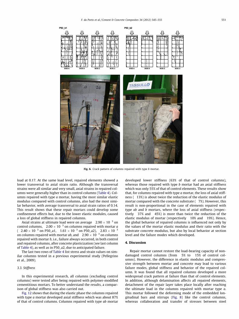
Fig. 6. Crack pattern of columns repaired with type b mortar.
F. da Porto et al. / Cement & Concrete Composites 34 (2012) 545–555 551
load at 0.17. At the same load level, repaired elements showed alower transversal to axial strain ratio. Although the transversalstrains were all similar and very small, axial strains in repaired col-umns were generally higher than in control columns (Table 4). Col-umns repaired with type a mortar, having the most similar elasticmodulus compared with control columns, also had the most simi-lar behavior, with average transversal to axial strain ratios of 0.14.This result shows that these repair mortars could develop someconfinement effects but, due to the lower elastic modules, causeda loss of global stiffness in repaired columns.
Axial strains at ultimate load were on average �2.90 � 10�3 oncontrol columns, �2.00 � 10�3 on columns repaired with mortar a(�2.40 � 10�3 on P50_a1, �1.61 � 10�3 on P50_a2), �2.83 � 10�3
on columns repaired with mortar ab, and �2.90 � 10�3 on columnsrepaired with mortar b, i.e., failure always occurred, in both controland repaired columns, after concrete plasticization (see last columnof Table 4), as well as in P50_a2, due to anticipated failure.
The last two rows of Table 4 list stress and strain values on sim-ilar columns tested in a previous experimental study (Pellegrinoet al., 2009).
3.3. Stiffness
In this experimental research, all columns (excluding controlcolumns) were tested after being repaired with polymer-modifiedcementitious mortars. To better understand the results, a compar-ison of global stiffness was also carried out.
Fig. 12 shows that during the elastic phase the columns repairedwith type a mortar developed axial stiffness which was about 87%of that of control columns. Columns repaired with type ab mortar
developed lower stiffness (63% of that of control columns),whereas those repaired with type b mortar had an axial stiffnesswhich was only 55% of that of control elements. These results showthat, for columns repaired with type a mortar, the loss of axial stiff-ness (�13%) is about twice the reduction of the elastic modulus ofmortar compared with the concrete substrate (�7%). However, thisresult is non-proportional in the case of elements repaired withtype ab and b mortars, where the loss of axial stiffness (respec-tively �37% and �45%) is more than twice the reduction of theelastic modulus of mortar (respectively �10% and �19%). Hence,the global behavior of repaired columns is influenced not only bythe values of the mortar elastic modulus and their ratio with thesubstrate concrete modulus, but also by local behavior at sectionlevel and the failure modes which developed.
4. Discussion
Repair mortar cannot restore the load-bearing capacity of non-damaged control columns (from �5% to �15% of control col-umns). However, the difference in elastic modulus and compres-sive strength between mortar and concrete may lead to variousfailure modes, global stiffness and behavior of the repaired col-umn. It was found that all repaired columns developed a morewidespread crack pattern at failure than that of control elements.In addition, although delamination affects all repaired elements,detachment of the repair layer takes place locally after reachingthe ultimate load in the columns repaired with mortar type a.This mortar followed the deforming mode of the embedded lon-gitudinal bars and stirrups (Fig. 8) like the control columns,whereas collaboration and transfer of stresses between steel

Fig. 7. Crack pattern of columns repaired with type ab mortar.
Table 3Results of axial tests.
Column Stress at ultimate load (N/mm2)
Ratio repaired column/controlcolumn
P0_1 25.55 –P0_2 28.49 –P50_a1 25.55 0.95P50_a2 25.18 0.93P50_b1 23.15 0.86P50_b2 22.97 0.85P50_ab1 23.36 0.86P50_ab2 23.38 0.86
552 F. da Porto et al. / Cement & Concrete Composites 34 (2012) 545–555
and mortar was less effective in the columns repaired with mor-tar type b and ab.
Analysis of stress–strain curves in Figs. 10 and 11 emphasizesthat the behavior of the columns repaired with mortar type a isclose to that of control elements, both in terms of mortar and rein-forcement bar deformation. The good properties of the mortar typea are also confirmed in Fig. 12. Although stiffness in all repairedcolumns was lower than that of control elements, during the elas-tic phase the columns repaired with mortar type a develop thesmallest loss of axial stiffness (�13%). Instead, in the case of repairlayers with mortar type b and ab, the reduction of axial stiffnesswas respectively �37% and �45%.
Considering the mechanical properties of mortar type a, it maybe argued that the elastic modulus of repair mortar, combined withappropriate values of compressive strength, is a crucial parameterin the effectiveness of the repair. In this work the best combination
of elastic modulus and compressive strength in a repair mortar isfound in mortar type a, characterized by an elastic modulus similarto that of the concrete substrate (�7%) and slightly higher com-pressive strength (+20%).
5. Conclusions
Compressive tests were carried out to evaluate the behavior ofreinforced concrete columns repaired on all four sides with threetypes of mortars.
The main conclusion was that repaired columns developed alower load capacity than non-damaged, non-repaired control ele-ments. For columns repaired with mortar a, the repair materialdid not restore the load-bearing capacity of non-damaged controlcolumns, although it gave acceptable results (95% of ultimatecapacity of control columns). Columns repaired with mortar breached an ultimate load which was 85% of the ultimate capacityof control columns, and columns repaired with mortar ab reachedan ultimate load of 86%. Columns repaired with a mortar having anelastic modulus similar to that of the substrate concrete and ahigher compressive strength (mortar a) did have some confiningeffect on the columns, as happens in non-damaged elements.
The results of a previous experimental study [6] showed that,for effective repair of axially loaded elements, it is necessary forthe mortar layer to include the reinforcement (both stirrups andlongitudinal bars). In that study, the repair was applied to onlyone side of the columns (Fig. 13). Comparing the results of the cur-

(a) concrete and bars P0_1 (b) concrete and bars P0_2
(c) repair and bars P50_a1 (d) repair and bars P50_a2
(e) repair and bars P50_b1 (f) repair and bars P50_b2
(g) repair and bars P50_ab1 (h) repair and bars P50_ab2
0
5
10
15
20
25
30
stre
ss [
N/m
m2 ]
stre
ss [
N/m
m2 ]
stre
ss [
N/m
m2 ]
stre
ss [
N/m
m2 ]
stre
ss [
N/m
m2 ]
stre
ss [
N/m
m2 ]
stre
ss [
N/m
m2 ]
stre
ss [
N/m
m2 ]
longitudinal bars
vertical DT
stirrups
horizontal DT
0
5
10
15
20
25
30
-4.0 -3.0 -2.0 -1.0 0.0 1.0 2.0 3.0 4.0
-4.0 -3.0 -2.0 -1.0 0.0 1.0 2.0 3.0 4.0
-4.0 -3.0 -2.0 -1.0 0.0 1.0 2.0 3.0 4.0
-4.0 -3.0 -2.0 -1.0 0.0 1.0 2.0 3.0 4.0-4.0 -3.0 -2.0 -1.0 0.0 1.0 2.0 3.0 4.0
-4.0 -3.0 -2.0 -1.0 0.0 1.0 2.0 3.0 4.0
-4.0 -3.0 -2.0 -1.0 0.0 1.0 2.0 3.0 4.0
-4.0 -3.0 -2.0 -1.0 0.0 1.0 2.0 3.0 4.0
longitudinal bars
vertical DT
stirrups
horizontal DT
0
5
10
15
20
25
30
longitudinal bars
vertical DT
stirrups
horizontal DT0
5
10
15
20
25
30
strain [10-3]
strain [10-3]
strain [10-3]strain [10-3]
strain [10-3]
strain [10-3] strain [10-3]
longitudinal bars
vertical DT
stirrups
horizontal DT
0
5
10
15
20
25
30
strain [10-3]
longitudinal bars
vertical DT
stirrups
horizontal DT
0
5
10
15
20
25
30
longitudinal bars
vertical DT
stirrups
horizontal DT
0
5
10
15
20
25
30
longitudinal bars
vertical DT
stirrups
horizontal DT
0
5
10
15
20
25
30
longitudinal bars
vertical DT
stirrups
horizontal DT
Fig. 8. Average stress–strain diagrams of all specimens.
F. da Porto et al. / Cement & Concrete Composites 34 (2012) 545–555 553
rent study with those of the previous one, we confirm that it is nec-essary to use mortars with elastic modulus at least similar or equalto that of the concrete substrate, and preferably higher compres-sive strength. The listed conclusions are based on a limited number
of mortar property variations and tests. It is thus recommendedthat more research be carried out on this topic, for complete andreliable knowledge of the influencing parameters to be taken intoaccount during the design and execution of interventions.

0.0
0.5
1.0
1.5
2.0
2.5
3.0
0.00 0.25 0.50 0.75 1.00
bar/c
olum
n st
rain
[-]
Normalized stress [-]
Columns P0Columns P50_aColumns P50_bColumns P50_ab
Fig. 9. Ratio of longitudinal bars and column strains, versus normalized axial stress.
0
5
10
15
20
25
30
-4.0 -3.5 -3.0 -2.5 -2.0 -1.5 -1.0 -0.5 0.0
stre
ss [N
/mm
2 ]st
ress
[N/m
m2 ]
strain[10-3]
strain[10-3]
column P0_1column P0_2column P50_a1column P50_a2column P50_b1column P50_b2column P50_ab1column P50_ab2
0
5
10
15
20
25
30
0.0 0.5 1.0 1.5 2.0
column P0_1
column P0_2
column P50_a1
column P50_a2
column P50_b1
column P50_b2
column P50_ab1
column P50_ab2
(a)
(b)
Fig. 10. Average stress-axial strain (a) and stress-transversal strain (b) on allcolumns.
0
5
10
15
20
25
30
-4.0 -3.5 -3.0 -2.5 -2.0 -1.5 -1.0 -0.5 0.0
stre
ss [N
/mm
2 ]
strain[10-3]
bars P0_1
bars P0_2
bars P50_a1
bars P50_a2
bars P50_b1
bars P50_b2
bars P50_ab1
bars P50_ab2
0
5
10
15
20
25
30
0.0 0.5 1.0 1.5 2.0
stre
ss [N
/mm
2 ]
strain[10-3]
stirrups P0_1
stirrups P0_2
stirrups P50_a1
stirrups P50_a2
stirrups P50_b1
stirrups P50_b2
stirrups P50_ab1
stirrups P50_ab2
(a)
(b)
Fig. 11. Average stress-axial strain on longitudinal bars (a) and stress-transversalstrain on stirrups (b).
Table 4Stress and strain values of axial tests.
Column 1/3 Ultimate load Ultimate load
Stress (N/mm2) Transv. strain (a) (10�3) Axial strain (b) (10�3) (a)/(b) Stress (N/mm2) Axial strain (10�3)
P0_1 8.51 0.05 �0.37 �0.14 25.55 �2.83P0_2 9.50 0.08 �0.39 �0.21 28.49 �2.96P50_a1 8.50 0.05 �0.49 �0.10 25.55 �2.40P50_a2 8.39 0.07 �0.39 �0.18 25.18 �1.61P50_b1 7.71 0.07 �0.88 �0.08 23.15 �2.93P50_b2 7.65 0.06 �0.60 �0.10 22.97 �2.88P50_ab1 7.78 0.05 �0.51 �0.10 23.36 �2.87P50_ab2 7.78 0.04 �0.63 �0.06 23.38 �2.78P50_a2009 9.70 0.12 �0.74 �0.16 29.00 �3.30P50_b2009 9.30 0.24 �1.00 �0.24 27.80 �2.71
0
500
1000
1500
2000
2500
3000
3500
4000
P0 P50_a P50_b P50_ab
100%
87%
55%63%
100%93%
81%90%
Stiff
ness
-El
astic
mod
ulus
Column type
Column stiffness [x1000 N/mm]Material elastic modulus [x10 N/mm2]
Fig. 12. Average stiffness of columns and elastic modulus of concrete/mortar.
554 F. da Porto et al. / Cement & Concrete Composites 34 (2012) 545–555

(a) P50_a_2009 (b) P50_b_2009
0
5
10
15
20
25
30
-4.0 -3.0 -2.0 -1.0 0.0 1.0 2.0 3.0 4.0 -4.0 -3.0 -2.0 -1.0 0.0 1.0 2.0 3.0 4.0
Stre
ss [N
/mm
2 ]
Strain [10-3]
transv. strain concretetransv. strain repairaxial strain concreteaxial strain repair
0
5
10
15
20
25
30
Stre
ss [N
/mm
2 ]
Strain [10-3]
transv. strain concretetransv. strain repairaxial strain concreteaxial strain repair
Fig. 13. Average stress–strain diagrams on concrete and repairs (previous experimental study).
F. da Porto et al. / Cement & Concrete Composites 34 (2012) 545–555 555
Acknowledgements
The authors would like to thank Tassullo S.p.A., which providedmaterials and samples for experimental testing; A. Giacometti, P.Girardello and D. Gò for their contribution to the experimentalinvestigation developed during their MSc theses and M. Dalla Ben-etta for supervising experimental work. Experimental tests werecarried out at the Laboratory of Structural Materials Testing ofthe University of Padova.
References
[1] Pellegrino C, Modena C. Flexural strengthening of real-scale RC and PRC beamswith end-anchored pre-tensioned FRP laminates. Struct J ACI2009;106(3):319–28.
[2] Pellegrino C, Modena C. An experimentally based analytical model for shearcapacity of FRP strengthened reinforced concrete beams. Mech Compos Mater2008;44(3):231–44.
[3] Pellegrino C, Tinazzi D, Modena C. An experimental study on bond behaviorbetween concrete and FRP reinforcement. J Compos Constr 2008;12(2):180–9.
[4] Emberson NK, Mays GC. Significance of property mismatch in the patch repairof structural concrete. Part 2. Axially loaded reinforced concrete members.Mag Concr Res 1990;42(152):161–70.
[5] Emberson NK, Mays GC. Significance of property mismatch in the patch repairof structural concrete Part 2. Reinforced concrete members in flexure. MagConcr Res 1996;48(174):45–57.
[6] Pellegrino C, da Porto F, Modena C. Rehabilitation of reinforced concrete axiallyloaded elements with polymer-modified cementicious mortar. Constr BuildMater Elsevier 2009;23(10):3129–37.
[7] Pellegrino C, da Porto F, Modena C. Experimental behaviour of reinforcedconcrete elements repaired with polymer-modified cementicious mortar.Mater Struct/Matériauxet Constr Rilem 2011;44(2):517–27.
[8] Mangat PS, O’Flaherty FJ. Influence of elastic modulus on stress redistributionand cracking in repair patches. Cem Concr Res Elsevier 2000;30(1):125–36.
[9] Sharif A, KalimurRahman M, Al-Gahtani AS, Hameeduddin M. Behaviour ofpatch repair of axially loaded reinforced concrete beams. Cem Concr ComposElsevier 2006;28(8):734–41.
[10] Tokushige H, Kawakami M, Todate H, Doiuchi K. Stress and deformation ofconcrete members repaired by polymer mortar. Trans Jpn Concr Inst J-east1999;21(1):89–94.
[11] Courard L. Parametric study for the creation of the interface between concreteand repair products. Mater Struct/Matériaux et Constr, Rilem2000;33(1):65–72.
[12] Kamada T, Li VC. The effect of surface preparation on the fracture behaviour ofECC/concrete repair system. Cem Concr Compos Elsevier 2000;22(6):423–31.
[13] Garbacz A, Gorka M, Courard L. Effect of concrete surface treatment onadhesion in repair system. Mag Concr Res 2005;57(1):49–60.
[14] Yubin S, Huicai X, Wei D. A new method of controlling shrinkage cracking inrepaired concrete structures using an interface layer of carbon fiber reinforcedcement mortar. vol. 3(2). CMC, Tech Science Press; 2006. p. 49–53.
[15] European Committee for Standardization. Eurocode 2 – Design of concretestructures. – Part 1-1: General rules and rules for buildings. EN 1992-1-1,Brussels, Belgium; 2004.
[16] European Committee for Standardization. Products and systems for theprotection and repair of concrete structures – Test methods – Determinationof compressive strength of repair mortar. EN 12190. Brussels, Belgium; 1998.
[17] European Committee for Standardization. Testing hardened concrete. EN12390. Brussels, Belgium; 2000.
[18] Ente Nazionale Italiano di Unificazione. Tests of concretes. Determination ofstatic modulus of elasticity in compression. UNI 6556, Milan, Italy; 1976.
[19] European Committee for Standardization. Methods of test for mortar formasonry – Part 1: Determination of particle size distribution (by sieveanalysis). EN 1015-1. Brussels, Belgium; 2006.
[20] American Society for Testing and Materials. Standard Test Method forSoundness of Aggregates by Use of Sodium Sulfate or Magnesium Sulfate.ASTM C88, West Conshohocken. Pa; 2005.
[21] European Committee for Standardization. Methods of test for mortar formasonry – Part 10: Determination of dry bulk density of hardened mortar. EN1015-10. Brussels, Belgium; 2006.
[22] European Committee for Standardization. Paints, Varnishes, Organic coatings,Coating processes, Coatings, Stone, Concretes, Protective coatings, Carbondioxide, Permeability, Permeability measurement, Porous materials. EN 1062-6, Brussels, Belgium; 2002.