Enhancement of flexural behaviour of CFRP-strengthened reinforced concrete beams using engineered...
12
Enhancement of flexural behaviour of CFRP-strengthened reinforced concrete beams using engineered cementitious composites transition layer Hamdy M. Afefy*, Nesreen Kassem 1 and Mohamed Hussein 2 Structural Engineering Department, Faculty of Engineering, Tanta University, Tanta, Egypt (Received 22 November 2013; final version received 7 March 2014; accepted 31 March 2014) This paper aimed to develop and evaluate an efficient strengthening method for reinforced concrete beams, based on engineered cementitious composites (ECC) to be applied as a transition layer prior to the application of the carbon fibre- reinforced polymer (CFRP) strengthening sheet. The role of the proposed transition layer is to control the cracking of concrete and detain or even avoid premature de-bonding of the strengthening CFRP sheets. As the ability of the transition layer to exhibit a strain hardening behaviour is mainly dependent on the used fibre volumetric ratio, three ECC mixes with three different polypropylene fibre volumetric ratios were used (fibre volumetric ratio of 0.5%, 1% and 1.5%). The experimental results showed that while the used CFRP strengthening sheet can increase the ultimate load by about 28.8% compared with the control un-strengthened beam, this increase can reach about 48.5% by applying the same CFRP sheet to the proposed ECC transition layer that contains a fibre volumetric ratio of 1.5%. Moreover, this layer integrated with the mention ratio of the fibre content enabled the CFRP sheet to be in a complete contact with the strengthened beam without any de-bonding up the rupture of the CFRP sheet at failure. Keywords: crack width; cracks spacing; carbon fibre-reinforced polymers; ductility; engineered cementitious composites; reinforced concrete beams; strengthening 1. Introduction The progressively rapid deterioration of infrastructure is becoming a prime problem for both researchers and engineers in construction industry. Engineers are con- fronted with the continuous challenge of developing new techniques by researchers in order to repair, replace or rehabilitate the existing structures. Deterioration in all types of reinforced concrete (RC) structures is further provoked by load- induced stresses greater than the design stress, excessive concentrations of chlorides in construc- tion materials, by high humidity and temperatures, and by marine environments. The construction industry is urgently in need of non-corrosive materials as alternatives to steel reinforcement or, at least, a proper protection for the main steel and its concrete tension cover. In order to remedy this problem, various solutions ranging from replacement of the structure to strengthening with a variety of techniques have been proposed. In addition, many methods to counter the threat of corrosion in steel reinforcement such as epoxy coatings, cathodic protection, increased concrete cover thickness and polymer concrete have been proposed, but none of these measures has provided a long-term solution. In the current research, the tension zone around the main tension steel of the test beams was replaced by an engineered cementitious compositess (ECC) material and then the strengthening carbon fibre-reinforced polymer (CFRP) sheets were bonded to its bottom surface. That was done for the aim of enhancing the strengthened beams cracking behaviour resulting in improved bond characteristics, which in turn increases the strengthening efficiency along with providing protection for the main tension steel, simultaneously. Fibre-reinforced polymer (FRP) materials as a new construction strengthening materials have been developed and used for recent, current and potential applications that cover both new and existing structures. FRP composites have become more popular in recent years due to the reduction in their cost, combined with newer under- standing of the versatility and benefits of the material properties. Among different types of FRP materials, a CFRP is used extensively in the structural engineering field. The externally bonded reinforcement (EBR) technique has been more generally applied due to its simple installation procedure. Design guidelines and specifications have also been established well for this system (ACI 440.2R-08). In particular, their practical implementations for strengthening by epoxy bonding are numerous (Benzarti, Freddi, & Fre ´mond, 2011; Cromwell, Harries, & Shahrooz, 2011; Jumaat, Rahman, & Rahman, q 2014 Taylor & Francis *Corresponding author. Email: [email protected] Structure and Infrastructure Engineering, 2014 http://dx.doi.org/10.1080/15732479.2014.930497
Transcript of Enhancement of flexural behaviour of CFRP-strengthened reinforced concrete beams using engineered...

Enhancement of flexural behaviour of CFRP-strengthened reinforced concrete beams usingengineered cementitious composites transition layer
Hamdy M. Afefy*, Nesreen Kassem1 and Mohamed Hussein2
Structural Engineering Department, Faculty of Engineering, Tanta University, Tanta, Egypt
(Received 22 November 2013; final version received 7 March 2014; accepted 31 March 2014)
This paper aimed to develop and evaluate an efficient strengthening method for reinforced concrete beams, based onengineered cementitious composites (ECC) to be applied as a transition layer prior to the application of the carbon fibre-reinforced polymer (CFRP) strengthening sheet. The role of the proposed transition layer is to control the cracking ofconcrete and detain or even avoid premature de-bonding of the strengthening CFRP sheets. As the ability of the transitionlayer to exhibit a strain hardening behaviour is mainly dependent on the used fibre volumetric ratio, three ECC mixes withthree different polypropylene fibre volumetric ratios were used (fibre volumetric ratio of 0.5%, 1% and 1.5%). Theexperimental results showed that while the used CFRP strengthening sheet can increase the ultimate load by about 28.8%compared with the control un-strengthened beam, this increase can reach about 48.5% by applying the same CFRP sheet tothe proposed ECC transition layer that contains a fibre volumetric ratio of 1.5%. Moreover, this layer integrated with themention ratio of the fibre content enabled the CFRP sheet to be in a complete contact with the strengthened beam withoutany de-bonding up the rupture of the CFRP sheet at failure.
Keywords: crack width; cracks spacing; carbon fibre-reinforced polymers; ductility; engineered cementitious composites;reinforced concrete beams; strengthening
1. Introduction
The progressively rapid deterioration of infrastructure is
becoming a prime problem for both researchers and
engineers in construction industry. Engineers are con-
fronted with the continuous challenge of developing new
techniques by researchers in order to repair, replace or
rehabilitate the existing structures. Deterioration in all
types of reinforced concrete (RC) structures is further
provoked by load- induced stresses greater than the design
stress, excessive concentrations of chlorides in construc-
tion materials, by high humidity and temperatures, and by
marine environments. The construction industry is
urgently in need of non-corrosive materials as alternatives
to steel reinforcement or, at least, a proper protection for
the main steel and its concrete tension cover. In order to
remedy this problem, various solutions ranging from
replacement of the structure to strengthening with a variety
of techniques have been proposed.
In addition, many methods to counter the threat of
corrosion in steel reinforcement such as epoxy coatings,
cathodic protection, increased concrete cover thickness
and polymer concrete have been proposed, but none of
these measures has provided a long-term solution. In the
current research, the tension zone around the main tension
steel of the test beams was replaced by an engineered
cementitious compositess (ECC) material and then the
strengthening carbon fibre-reinforced polymer (CFRP)
sheets were bonded to its bottom surface. That was done
for the aim of enhancing the strengthened beams cracking
behaviour resulting in improved bond characteristics,
which in turn increases the strengthening efficiency along
with providing protection for the main tension steel,
simultaneously.
Fibre-reinforced polymer (FRP) materials as a new
construction strengthening materials have been developed
and used for recent, current and potential applications that
cover both new and existing structures. FRP composites
have become more popular in recent years due to the
reduction in their cost, combined with newer under-
standing of the versatility and benefits of the material
properties. Among different types of FRP materials, a
CFRP is used extensively in the structural engineering
field. The externally bonded reinforcement (EBR)
technique has been more generally applied due to its
simple installation procedure. Design guidelines and
specifications have also been established well for this
system (ACI 440.2R-08). In particular, their practical
implementations for strengthening by epoxy bonding are
numerous (Benzarti, Freddi, & Fremond, 2011; Cromwell,
Harries, & Shahrooz, 2011; Jumaat, Rahman, & Rahman,
q 2014 Taylor & Francis
*Corresponding author. Email: [email protected]
Structure and Infrastructure Engineering, 2014
http://dx.doi.org/10.1080/15732479.2014.930497
2011; Ombres, 2010; Rasheed, Harrison, Peterman, &
Alkhrdaji, 2010).
Although external strengthening of RC beams with
epoxy-bonded CFRP has been established as an effective
tool for increasing flexural and/or shear strength, the
method still suffers from some drawbacks. Many of these
drawbacks are attributed to the characteristics of currently
available commercial CFRP-strengthening systems. Even
though CFRPs have high strength, they are very brittle.
When loaded in tension, FRPs exhibit a linear stress–
strain behaviour up to failure, without exhibiting a yield
plateau or any indication of an impending failure. As FRPs
behave differently than steel, they consequently suffer
from a significant loss in beam ductility, particularity
when CFRPs are used for flexural strengthening of RC
beams (Arduini & Nanni, 1997; Bencardino, Spadea, &
Swamy 2002; Lee, Pan, & Ma, 2004; Saadatmanesh &
Ehsani, 1991; Spadea, Swamy, & Bencardino, 2001;
Toutanji, Zhao, & Zhang, 2006).
Over the years, many studies focusing on the
behaviour of CFRP-strengthened beams have been
conducted to better understand their behaviour under
different loading conditions, aiming also to develop the
best technique for the application of CFRP fabric sheets
and strips. Ehsan, Sobuz, and Sutan (2011) verified that the
attachment of CFRP laminates with edge strip plates had
substantially influenced the performance of CFRP-
strengthened beams. In addition, the important practical
issues that were encountered in strengthening of beams
with different types and different thicknesses of FRP were
addressed (Murali & Pannirselvam, 2011). Hence, a
simple method of applying FRP for strengthening the
beam with different FRP types with different thicknesses
was proposed. In addition to the practical experience for
choosing the strengthening configuration, design guide-
lines for FRP RC structures were stipulated (Pilakoutas,
Neocleous, Guadagnini, & Matthys, 2011)
ECC is a special category of the new generation of
high-performance fibre-reinforced cementitious compo-
sites with microstructures tailored according to micro-
mechanics theory, featuring high ductility and durability
characteristics (Dhawale & Joshi 2013; Li, 1993, 2012; Li
& Li, 2011a, 2011b). ECC’s high tensile ductility,
deformation compatibility with existing concrete and
self-controlled micro-crack width lead to their superior
durability under various mechanical and environmental
loading conditions such as fatigue, freezing and thawing,
chloride exposure and drying shrinkage (Li & Li, 2008,
2011a, 2011b; Sahmaran, Li, & Li, 2007). Experience of
the use of the ECC material in a bridge deck patch repair
case showed that high tensile strain capacity is one of the
most important properties of a durable repair material to
resist typical failures in repaired systems and that such
high tensile strain capacity can be achieved economically
in ECC materials (Li, 2004).
ECC is a mortar-based composite that is reinforced
with short random fibres, such as polyethylene (PE) or
polyvinyl alcohol (PVA). The use of PVA fibres has better
tensile crack-bridging properties while the use of PE fibres
shows a better compressive behaviour (Fischer & Li,
2007). ECC is a micromechanically designed material that
uses a micromechanical model to tailor-make the required
properties. By using this micromechanical tool, the fibre
amount used in the ECC is typically less than 2% by
volume. The moderately low fibre content has also made
shotcreting ECC viable. Furthermore, the most expensive
component of the composite fibres is minimised resulting
in ECC that is more acceptable to the highly cost-sensitive
construction industry (Dhawale & Joshi, 2013). Therefore,
ECC is designed to resist large tensile and shear forces but
at the same time has compatible properties, such as
compressive strength and thermal expansion, to ordinary
concrete based on Portland cement (Li, 2002).
Since the introduction of this material two decades ago,
ECC has undergone major evolution in both materials
development and the range of emerging applications. A
variety of experiments have been performed to assess the
performance of ECC at the structural level (Fischer & Li,
2003a, 2003b; Fukuyama, Matsuzaki, Nakano, & Sato
1999; Li & Fischer, 2002) for both seismic and non-seismic
structural applications. These experiments provide new
insights into how the material properties enhance the
structural performance of the structure. Under tensile
loading, in contrast to normal concrete where a single
unstable crack develops into a failure plane, a characteristic
of ECC is the development of multiple stable micro-cracks,
bridged by fibres (Spagnoli, 2009). As amicro-crack forms,
the fibres within the matrix bridge the crack, preventing it
from propagating into a failure plane. The multiple micro-
cracking behaviour of ECC is dependent on the fibre crack-
bridging law and on the degree of heterogeneity in the
material. Crack initiation sites are typically at material
flaws, which in the majority of cases are bubbles of
entrapped air (voids). Crack initiation behaviour is
therefore influenced by the size and spatial distribution of
voids in the material (Wang & Li, 2004). Final failure
occurs when one of the multiple cracks forms a fracture
plane.
Many researchers have confirmed that applying CFRP
laminates to RC beams can increase both the ultimate load
carrying capacity and the stiffness of the beams. Further
observations proved that the application also delays the
cracking moment and mitigates the development of cracks
(FIB, 2001). Most of the investigations carried out on RC
members strengthened in flexure have indicated that EBR
technique cannot fully utilise the strength of the FRP
composites. Brittle failure due to premature FRP de-
bonding and concrete cover separation has been the most
common type of failure (Teng, Chen, Smith, & Lam
2001). CFRP composites have very desirable high
H.M. Afefy et al.2
strength, but cannot be utilised properly if there is a poor
FRP–concrete bond. Typically, failure of a FRP–concrete
bond occurs within the concrete just a few millimetres
below the surface (Chen & Teng, 2001; Pan & Leung
2007; Wu, Hu, Wu, & Zheng, 2011; Yuan, Teng, Seracino,
Wu, & Yao, 2004). The de-bonding mechanism results in
the loss of the composite action between the concrete and
FRP laminates and initiates when high interfacial shear
and normal stresses exceed the strength of concrete.
The current research is undertaken in the aim of
enhancing the bond characteristics between the externally
bonded CFRP (EB-CFRP) strengthening materials and the
substrate concrete beams by replacing the concrete tension
zone around the main tension steel by an ECC transition
layer with different fibre contents. The polypropylene (PP)
fibres were used in the ECC material mix with three
different volume ratios in order to accomplish the
optimum ratio of fibre that can guarantee the complete
composite action between the CFRP sheets and the
substrate beams up to failure. That was done in order to be
able to utilise the overall strength of the CFRP sheets. At
this stage of research, the contribution of the ECC layer in
enhancing the ultimate strength was not of prime
importance. On the other hand, enforcing the CFRP
sheet to use its full tensile capacity was the most important
issue. In addition, this layer will provide a good protection
for the strengthened beams steel reinforcement against any
future attack that leads to corrosion.
2. Experimental work programme
2.1 Test beams
For the purposes of this study, six beams were fabricated
and cast then tested up to failure. The beams were divided
into two groups: the first group contained three beams
representing the reference beams, and the second group
contained three beams representing the CFRP-strength-
ened beams where three different fibre ratios were
implemented in the ECC transition layer. All beams had
the same concrete dimensions, i.e. the total length of the
beams was 2200mm while the centre-to-centre span was
2000mm. The beams cross section was 150mm width £300mm total depth. The main steel of the beams was two
high tensile steel bars of 12mm diameter representing a
reinforcement ratio of 0.56% that guarantee the tension-
controlled failure according to the current ECP 203 (2007)
and ACI 318-11 (2011) codes. The secondary steel was
two high tensile steel bars of 10mm diameter, while the
stirrups were mild steel bars of 8mm diameter and spaced
every 100mm all over the entire span of the beams.
Two beams of group 1 were completely cast with
concrete without any ECC transition layer, which
represented the control beam (B-C) and the reference
CFRP-strengthened beam (B-C-CF). The remaining
beam of group 1, beam B-C-ECC, was cast with 50mm
depth £ 150mm width ECC layer where the main
tension steel was embedded into the ECC transition layer
as illustrated in Figure 1. The second group, group 2,
represented the CFRP-strengthened beams. The three
beams had the same configuration as that of the reference
beam (B-C-ECC) as shown in Figure 1 but the used fibre
content ratio was the control parameter where it had three
ratios namely: 0.5%, 1% and 1.5% for the three beams. It
is worth mentioning that the fibre content of the reference
beam, B-C-ECC, was 1%.
All test beams were cast at the same time vertically in
wooden forms upside down where the tension sides were
at the top. Both beam B-C and B-C-CF were cast
completely with concrete, while the remaining four
beams were cast partially leaving the top 50mm depth
without concrete. Two days after casting, the standard
cubes, the concrete prism of 150mm 3 150mm 3 700 -
mm and the sides of the specimens B-C and B-C-CF were
stripped from the moulds and covered by plastic sheets,
while the sides of partially cast beams were left in
position to act as shuttering when ECC transition layers
were poured. The upper surface of all specimens were
cured by water until the 10th day and then allowed air-
drying. After about 4 weeks, the partially cast beams
were prepared for ECC pouring where the top surfaces
were roughened using chisel to remove slurry cement
from external surfaces of coarse aggregates. Before
pouring the ECC layers, the contact surfaces of the beams
were recleaned with brush and high-pressure air to ensure
a clean bonding surface, and then they were adequately
damped (Li, 2004). Just before casting the ECC layers, a
bonding agent (Addibond 65, provided by CMB
Company, Tanta, Egypt) was applied to the concrete
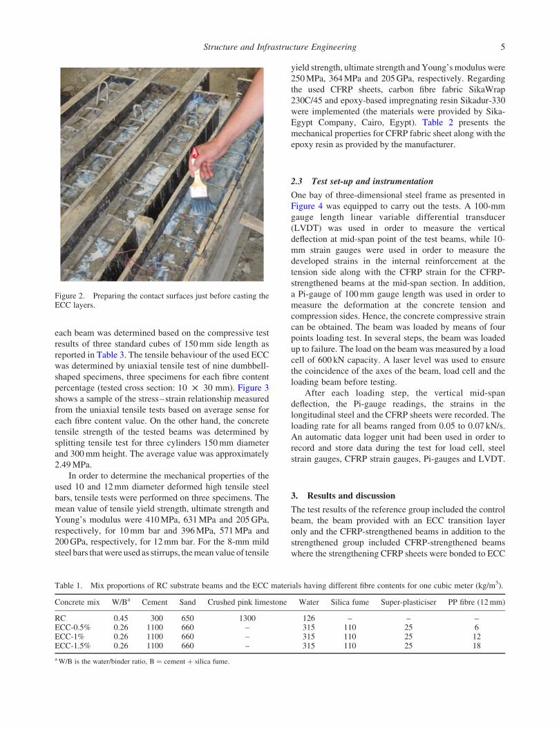
surfaces as illustrated in Figure 2. The upper surface of
the ECC layers were cured by water for 7 days and then
allowed air-drying until the testing day.
Four beams (B-C-CF, BS-0.5, BS-1 and BS-1.5) were
strengthened using CFRPs, in accordance with ACI 440
(2008) recommendations (ACI 440.2R-08) as shown in
Figure 1. Because the adopted strengthened beams are
considered as bond-critical application, surface prep-
aration requirements should be based on the intended
application of the CFRP system. The concrete surface
was prepared with abrasive techniques. The common
feature of the four strengthened beams was that all beams
were strengthened typically using CFRP sheets of
dimensions 150mm width, 0.13 mm thickness and
1800mm length extended at the tension side of the
beams. In addition, two 100-mm width CFRP anchorage
U-shaped sheets were used at both ends of the CFRP
sheets and ran up to 250mm depth at both sides in order
to prevent the premature peeling of the sheets at both
ends (Bilal, Amal, Hage, & Harajli, 2005; Sarah, James,
& Oguzhan, 2008).
Structure and Infrastructure Engineering 3

2.2 Material properties
The used concrete was made from ordinary Portland
cement (type I), natural sand and a mixture of crushed pink
limestone types I and II, as the coarse aggregate of
maximum size of 14mm, with a mixture proportion as
shown in Table 1 in order to obtain concrete with a target
strength of 25MPa. The actual compressive strength of the
used concrete was determined at the testing day as the
average of three standard cubes of 150mm side length as
reported in Table 3.
ECC layer was made with ingredients typically found
in concrete, including ordinary Portland cement, sand in
addition to silica fume and super-plasticiser based on poly-
carboxylic ether. The mix proportions of the ECC used as
strengthening materials are listed in Table 1. Water-to-
binder ratio (W/B) was 0.26, while 10% of the design
cement content was replaced by silica fume. High strength
PP fibre was selectively chosen, and its volume in mix was
varied to be 0.5%, 1% and 1.5%. The diameter and length
of the PP fibres were 0.025 and 12mm, respectively. The
tensile strength of the used PP fibres was 626MPa. PP
fibre can decline the brittleness of structure effectively by
improving the continuity and uniformity of concrete and
reduce the cracking obviously during plastic shrinkage.
The target compressive strength of the used ECC was
determined to be 60MPa, while the actual strength for
2200 mm
300
150
2 10
2 12
8@ 100 mm
750 mm 750 mm500 mm
2000 mm
Beam B-C
2000 mm
300
150
2 10
2 12
8@ 100 mm 50
50 mm thickness ECC layer (1% fiber content)
2000 mm
300
150
2 10
2 12
8@ 100 mm
EB-CFRP sheet (150 mm width x 0.13 mm thicness x 1800 length)
CFRP anchorage sheets
100 mm1600 mm100 mm
250
Beam B-C-ECC
Beam B-C-CF
300
150
2 10
2 12
8@ 100 mm 50
50 mm thickness ECC layer (0.5%, 1% and 1.5% fiber content)
Beams BS-0.5, BS-1, BS-1.5
EB-CFRP sheet (150 mm width x 0.13 mm thicness x 1800 length)
2000 mm
100 mm1600 mm100 mm
250
Figure 1. Concrete dimensions and reinforcement detailing for all tested beams.
H.M. Afefy et al.4
each beam was determined based on the compressive test
results of three standard cubes of 150mm side length as
reported in Table 3. The tensile behaviour of the used ECC
was determined by uniaxial tensile test of nine dumbbell-
shaped specimens, three specimens for each fibre content
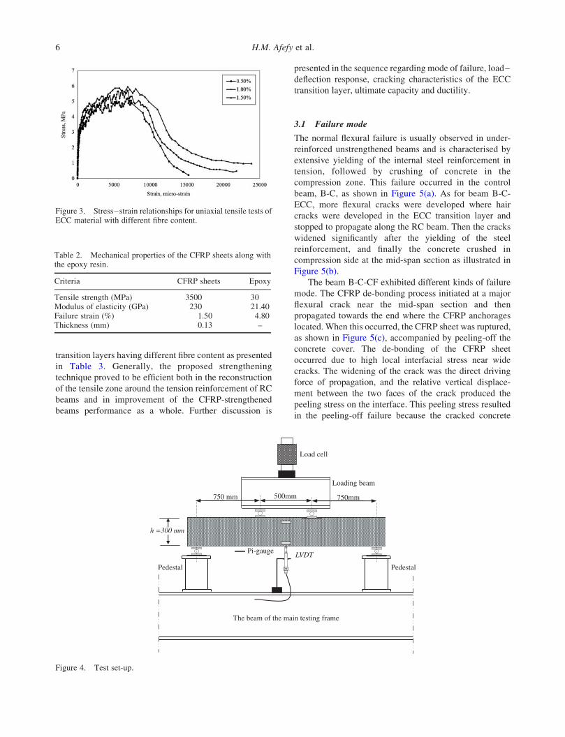
percentage (tested cross section: 10 £ 30 mm). Figure 3
shows a sample of the stress–strain relationship measured
from the uniaxial tensile tests based on average sense for
each fibre content value. On the other hand, the concrete
tensile strength of the tested beams was determined by
splitting tensile test for three cylinders 150mm diameter
and 300mm height. The average value was approximately
2.49MPa.
In order to determine the mechanical properties of the
used 10 and 12mm diameter deformed high tensile steel
bars, tensile tests were performed on three specimens. The
mean value of tensile yield strength, ultimate strength and
Young’s modulus were 410MPa, 631MPa and 205GPa,
respectively, for 10mm bar and 396MPa, 571MPa and
200GPa, respectively, for 12mm bar. For the 8-mm mild
steel bars thatwere used as stirrups, themeanvalue of tensile
yield strength, ultimate strength andYoung’s modulus were
250MPa, 364MPa and 205GPa, respectively. Regarding
the used CFRP sheets, carbon fibre fabric SikaWrap
230C/45 and epoxy-based impregnating resin Sikadur-330
were implemented (the materials were provided by Sika-
Egypt Company, Cairo, Egypt). Table 2 presents the
mechanical properties for CFRP fabric sheet along with the
epoxy resin as provided by the manufacturer.
2.3 Test set-up and instrumentation
One bay of three-dimensional steel frame as presented in
Figure 4 was equipped to carry out the tests. A 100-mm
gauge length linear variable differential transducer
(LVDT) was used in order to measure the vertical
deflection at mid-span point of the test beams, while 10-
mm strain gauges were used in order to measure the
developed strains in the internal reinforcement at the
tension side along with the CFRP strain for the CFRP-
strengthened beams at the mid-span section. In addition,
a Pi-gauge of 100mm gauge length was used in order to
measure the deformation at the concrete tension and
compression sides. Hence, the concrete compressive strain
can be obtained. The beam was loaded by means of four
points loading test. In several steps, the beam was loaded
up to failure. The load on the beam was measured by a load
cell of 600 kN capacity. A laser level was used to ensure
the coincidence of the axes of the beam, load cell and the
loading beam before testing.
After each loading step, the vertical mid-span
deflection, the Pi-gauge readings, the strains in the
longitudinal steel and the CFRP sheets were recorded. The
loading rate for all beams ranged from 0.05 to 0.07 kN/s.
An automatic data logger unit had been used in order to
record and store data during the test for load cell, steel
strain gauges, CFRP strain gauges, Pi-gauges and LVDT.
3. Results and discussion
The test results of the reference group included the control
beam, the beam provided with an ECC transition layer
only and the CFRP-strengthened beams in addition to the
strengthened group included CFRP-strengthened beams
where the strengthening CFRP sheets were bonded to ECC
Table 1. Mix proportions of RC substrate beams and the ECC materials having different fibre contents for one cubic meter (kg/m3).
Concrete mix W/Ba Cement Sand Crushed pink limestone Water Silica fume Super-plasticiser PP fibre (12mm)
RC 0.45 300 650 1300 126 – – –ECC-0.5% 0.26 1100 660 – 315 110 25 6ECC-1% 0.26 1100 660 – 315 110 25 12ECC-1.5% 0.26 1100 660 – 315 110 25 18
aW/B is the water/binder ratio, B ¼ cement þ silica fume.
Figure 2. Preparing the contact surfaces just before casting theECC layers.
Structure and Infrastructure Engineering 5
transition layers having different fibre content as presented
in Table 3. Generally, the proposed strengthening
technique proved to be efficient both in the reconstruction
of the tensile zone around the tension reinforcement of RC
beams and in improvement of the CFRP-strengthened
beams performance as a whole. Further discussion is
presented in the sequence regarding mode of failure, load–
deflection response, cracking characteristics of the ECC
transition layer, ultimate capacity and ductility.
3.1 Failure mode
The normal flexural failure is usually observed in under-
reinforced unstrengthened beams and is characterised by
extensive yielding of the internal steel reinforcement in
tension, followed by crushing of concrete in the
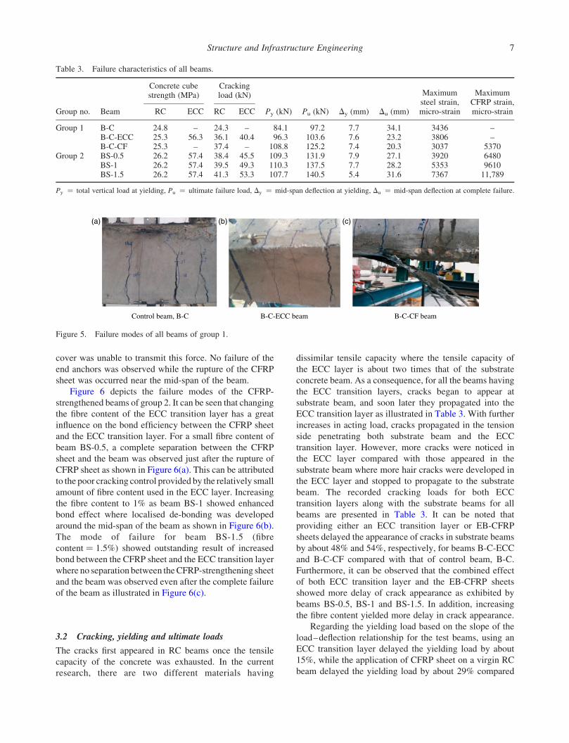
compression zone. This failure occurred in the control
beam, B-C, as shown in Figure 5(a). As for beam B-C-
ECC, more flexural cracks were developed where hair
cracks were developed in the ECC transition layer and
stopped to propagate along the RC beam. Then the cracks
widened significantly after the yielding of the steel
reinforcement, and finally the concrete crushed in
compression side at the mid-span section as illustrated in
Figure 5(b).
The beam B-C-CF exhibited different kinds of failure
mode. The CFRP de-bonding process initiated at a major
flexural crack near the mid-span section and then
propagated towards the end where the CFRP anchorages
located. When this occurred, the CFRP sheet was ruptured,
as shown in Figure 5(c), accompanied by peeling-off the
concrete cover. The de-bonding of the CFRP sheet
occurred due to high local interfacial stress near wide
cracks. The widening of the crack was the direct driving
force of propagation, and the relative vertical displace-
ment between the two faces of the crack produced the
peeling stress on the interface. This peeling stress resulted
in the peeling-off failure because the cracked concrete
Table 2. Mechanical properties of the CFRP sheets along withthe epoxy resin.
Criteria CFRP sheets Epoxy
Tensile strength (MPa) 3500 30Modulus of elasticity (GPa) 230 21.40Failure strain (%) 1.50 4.80Thickness (mm) 0.13 –
Figure 3. Stress–strain relationships for uniaxial tensile tests ofECC material with different fibre content.
750 mm 500mm 750mm
Pedestal
h =300 mm
Load cell
LVDT
Pedestal
Pi-gauge
Loading beam
The beam of the main testing frame
Figure 4. Test set-up.
H.M. Afefy et al.6
cover was unable to transmit this force. No failure of the
end anchors was observed while the rupture of the CFRP
sheet was occurred near the mid-span of the beam.
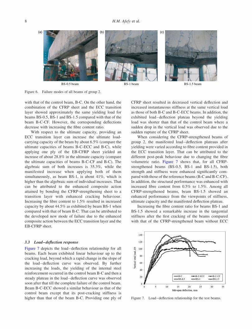
Figure 6 depicts the failure modes of the CFRP-
strengthened beams of group 2. It can be seen that changing
the fibre content of the ECC transition layer has a great
influence on the bond efficiency between the CFRP sheet
and the ECC transition layer. For a small fibre content of
beam BS-0.5, a complete separation between the CFRP
sheet and the beam was observed just after the rupture of
CFRP sheet as shown in Figure 6(a). This can be attributed
to the poor cracking control provided by the relatively small
amount of fibre content used in the ECC layer. Increasing
the fibre content to 1% as beam BS-1 showed enhanced
bond effect where localised de-bonding was developed
around the mid-span of the beam as shown in Figure 6(b).
The mode of failure for beam BS-1.5 (fibre
content ¼ 1.5%) showed outstanding result of increased
bond between the CFRP sheet and the ECC transition layer
where no separation between theCFRP-strengthening sheet
and the beam was observed even after the complete failure
of the beam as illustrated in Figure 6(c).
3.2 Cracking, yielding and ultimate loads
The cracks first appeared in RC beams once the tensile
capacity of the concrete was exhausted. In the current
research, there are two different materials having
dissimilar tensile capacity where the tensile capacity of
the ECC layer is about two times that of the substrate
concrete beam. As a consequence, for all the beams having
the ECC transition layers, cracks began to appear at
substrate beam, and soon later they propagated into the
ECC transition layer as illustrated in Table 3. With further
increases in acting load, cracks propagated in the tension
side penetrating both substrate beam and the ECC
transition layer. However, more cracks were noticed in
the ECC layer compared with those appeared in the
substrate beam where more hair cracks were developed in
the ECC layer and stopped to propagate to the substrate
beam. The recorded cracking loads for both ECC
transition layers along with the substrate beams for all
beams are presented in Table 3. It can be noted that
providing either an ECC transition layer or EB-CFRP
sheets delayed the appearance of cracks in substrate beams
by about 48% and 54%, respectively, for beams B-C-ECC
and B-C-CF compared with that of control beam, B-C.
Furthermore, it can be observed that the combined effect
of both ECC transition layer and the EB-CFRP sheets
showed more delay of crack appearance as exhibited by
beams BS-0.5, BS-1 and BS-1.5. In addition, increasing
the fibre content yielded more delay in crack appearance.
Regarding the yielding load based on the slope of the
load–deflection relationship for the test beams, using an
ECC transition layer delayed the yielding load by about
15%, while the application of CFRP sheet on a virgin RC
beam delayed the yielding load by about 29% compared
Table 3. Failure characteristics of all beams.
Concrete cubestrength (MPa)
Crackingload (kN) Maximum
steel strain,micro-strain
MaximumCFRP strain,micro-strainGroup no. Beam RC ECC RC ECC Py (kN) Pu (kN) Dy (mm) Du (mm)
Group 1 B-C 24.8 – 24.3 – 84.1 97.2 7.7 34.1 3436 –B-C-ECC 25.3 56.3 36.1 40.4 96.3 103.6 7.6 23.2 3806 –B-C-CF 25.3 – 37.4 – 108.8 125.2 7.4 20.3 3037 5370
Group 2 BS-0.5 26.2 57.4 38.4 45.5 109.3 131.9 7.9 27.1 3920 6480BS-1 26.2 57.4 39.5 49.3 110.3 137.5 7.7 28.2 5353 9610BS-1.5 26.2 57.4 41.3 53.3 107.7 140.5 5.4 31.6 7367 11,789
Py ¼ total vertical load at yielding, Pu ¼ ultimate failure load, Dy ¼ mid-span deflection at yielding, Du ¼ mid-span deflection at complete failure.
B-C-ECC beam B-C-CF beam Control beam, B-C
(a) (b) (c)
Figure 5. Failure modes of all beams of group 1.
Structure and Infrastructure Engineering 7
with that of the control beam, B-C. On the other hand, the
combination of the CFRP sheet and the ECC transition
layer showed approximately the same yielding load for
beams BS-0.5, BS-1 and BS-1.5 compared with that of the
beam B-C-CF. However, the corresponding deflections
decrease with increasing the fibre content ratio.
With respect to the ultimate capacity, providing an
ECC transition layer can increase the ultimate load-
carrying capacity of the beam by about 6.5% (compare the
ultimate capacities of beams B-C-ECC and B-C), while
applying one ply of the EB-CFRP sheet yielded an
increase of about 28.8% in the ultimate capacity (compare
the ultimate capacities of beams B-C-CF and B-C). The
algebraic sum of both increases is 35.3%, while the
manifested increase when applying both of them
simultaneously, as beam BS-1, is about 41%, which is
higher than the algebraic sum of individual increases. That
can be attributed to the enhanced composite action
attained by bonding the CFRP-strengthening sheet to a
transition layer with enhanced cracking behaviour.
Increasing the fibre content to 1.5% resulted in increased
capacity by about 44.5% as exhibited by beam BS-1 when
compared with that of beam B-C. That can be attributed to
the developed new mode of failure due to the enhanced
composite action between the ECC transition layer and the
EB-CFRP sheet.
3.3 Load–deflection response
Figure 7 depicts the load–deflection relationship for all
beams. Each beam exhibited linear behaviour up to the
cracking load, beyond which a rapid change in the slope of
the load–deflection curve was observed. By further
increasing the loads, the yielding of the internal steel
reinforcement occurred in the control beam B-C and then a
steady plateau in the load–deflection curve was observed
soon after that till the complete failure of the control beam.
Beam B-C-ECC showed a similar behaviour as that of the
control beam except that its post-cracking stiffness is
higher than that of the beam B-C. Providing one ply of
CFRP sheet resulted in decreased vertical deflection and
increased instantaneous stiffness at the same vertical load
as those of both B-C and B-C-ECC beams. In addition, the
exhibited load–deflection plateau beyond the yielding
load was shorter than that of the control beam where a
sudden drop in the vertical load was observed due to the
sudden rupture of the CFRP sheet.
When considering the CFRP-strengthened beams of
group 2, the manifested load–deflection plateaus after
yielding were varied according to fibre content provided in
the ECC transition layer. That can be attributed to the
different post-peak behaviour due to changing the fibre
volumetric ratio. Figure 7 shows that, for all CFRP-
strengthened beams (BS-0.5, BS-1 and BS-1.5), both
strength and stiffness were enhanced significantly com-
pared with those of the reference beams (B-C and B-C-CF).
In addition, the structural performance was enhanced with
increased fibre content from 0.5% to 1.5%. Among all
CFRP-strengthened beams, beam BS-1.5 showed an
enhanced performance from the viewpoints of stiffness,
ultimate capacity and the manifested deflection plateau.
Increasing the fibre content ratio for beams BS-1 and
BS-1.5 showed a remarkable increase in the tangential
stiffness after the first cracking of the beams compared
with that of the CFRP-strengthened beam without ECC
BS-1.5 beamBS-1 beamBS-0.5 beam
(a) (b) (c)
Figure 6. Failure modes of all beams of group 2.
Figure 7. Load–deflection relationship for the test beams.
H.M. Afefy et al.8

transition layer. After yielding of the main tension steel,
the combined behaviour of both the CFRP sheet and the
ECC transition layer controlled the behaviour. For beam
BS-0.5, approaching failure state, the CFRP sheet began to
de-bond that showed increased deflection with small
increased load. That was due to the strain hardening
behaviour of the ECC layer. With further loading, the
CFRP sheet was ruptured suddenly resulting in a step drop
in the resisting load.
For beam BS-1, a similar trend was noticed as
manifested by the beam BS-0.5 with higher stiffness and
resisting load. That can be attributed to the enhanced
bond characteristics between the EB-CFRP sheet and the
ECC transition layer which retained the de-bonding and
mitigated its propagation of the CFRP sheet compared
with that exhibited by the beam BS-0.5. Regarding beam
BS-1.5, a different mode of failure was noticed, while the
CFRP sheet was in complete bond to the ECC layer up to
failure, the ECC transition layer was failed resulting in
the separation between the RC substrate beam and the
ECC transition layer. That separation enforced the CFRP
sheet to work solely in an unbounded manner up to the
end of the test.
3.4 Crack width and crack spacing developed in theECC transition layer
Table 4 illustrates the measured major crack width along
with the average crack spacing developed in the ECC
transition layers along with those developed in the
concrete substrate of beam B-C-CF near the failure state.
It is well recognised that the de-bonding of the CFRP sheet
is highly dependent on the crack width and spacing,
because high local interfacial stress will be developed near
wide crack. The relative vertical displacement between the
two faces of the crack produces the peeling stress on the
interface. This peeling stress could result in the peeling-off
failure based on the ability of the cracked concrete cover to
transmit this force. This means that reducing the crack
width along with better crack distribution along the
interface of the CFRP sheets will result in better bond
characteristics along the CFRP interface up to failure.
Based on the test results of beam B-C-CF, the
relatively wide major crack (2mm) and the large crack
spacing (100mm) resulted in complete de-bonding in the
constant bending moment region as illustrated in Figure 5
(c). Increasing the fibre content of the ECC transition layer
from 0.5% to 1%, to 1.5% resulted in reduced crack width
along with reduced crack spacing that exhibited better
bond along the CFRP interface with the ECC transition
layer. As a result, the mode of failure had been changed
from de-bonding of the CFRP sheet as for beam BS-0.5 to
the rupture of the CFRP sheet without de-bonding as
manifested by beam BS-1.5.
Figure 8 displays the front view of both beams BS-1
and BS-1.5. It can be noticed that increasing the fibre
content ratio from 1% to 1.5% showed better crack
distribution where the number of cracks was doubled for
beam BS-1.5. On the other hand, separation between the
ECC transition layer and the substrate beam was happened
resulting in premature failure of the beam, BS-1.5. In other
words, the ultimate tensile capacity of the ECC transition
layer is a significant parameter and has to be increased in
order to show better enhancement in the ultimate capacity
of the beam due to the EB-CFRP sheet.
3.5 Ductility
Mufti, Newhook, & Tadros (1996) suggested that, in order
to determine the ductility of a RC beam strengthened with
Table 4. Cracking characteristics of the ECC transition layernear failure.
BeamMajor crackwidth (mm)
Average crackspacing (mm)
B-C-ECC 1 62B-C-CF 2a 100a
BS-0.5 0.42 55BS-1 0.39 38BS-1.5 0.35 19
a The crack width and spacing are for the substrate concrete beam.
Beam BS-1 Beam BS-1.5
Figure 8. Crack distribution along the ECC transition layer for beams BS-1 and BS-1.5.
Structure and Infrastructure Engineering 9

FRP, it is necessary to consider a deformability factor (DF)
and a strength factor (SF), and then combine these two
parameters to define an overall factor called performance
factor (PF). The DF can be determined by dividing the
deflection at ultimate limit state by the deflection at
serviceability limit state corresponding to a concrete
compressive strain of about 0.1%. SF is the ratio of the
ultimate load to the serviceability load.
Table 5 shows the DF, SF and PF for all tested beams.
It is empirically defined that the FRP-strengthened
members should present a PF larger than 4 to guarantee
an adequate ductile behaviour (Garcez, Meneghetti, &
Filho 2008). Table 5 also presents that the PF has been
increased when an ECC transition layer was implemented
solely (beam B-C-ECC) compared with that of the control
beam, B-C. On the other hand, the CFRP-strengthened
beam, B-C-CF, exhibited lower PF than that of the beam
B-C. In addition, its PF is lower than 4. When applied the
CFRP sheet on an ECC transition layer, the obtained PFs
are in-between those of beams B-C-ECC and B-C-CF.
Beam BS-1 manifested the highest PF among all
CFRP-strengthened beams. In addition, it showed
adequate ductility according to Garcez et al. (2008). The
beam BS-1.5 showed higher ductility compared with that
of the beam B-C-CF. However, it failed to exhibited
adequate ductility according to Garcez et al. (2008).
Despite that the beam BS-1.5 exhibited the highest SF
among all strengthened beam along with the control beam,
its DF showed the lowest one. That can be attributed to the
occurrence of local de-bonding between the ECC
transition layer and the substrate concrete and the
corresponding premature failure of of the ECC transition
layer.
4. Conclusions
Based on the studied hybrid strengthening techniques of
RC beams, loading scheme, the thickness of the ECC
transition layer, the configuration of the EB-CFRP sheet
and according to the used concrete dimensions and
reinforcement detailing, the following conclusions can be
drawn:
(1) Based on the results of the present experimental
programme, it can be concluded that the proposed
strengthening technique, even with the possibility
of further improvements, as any other technique,
proved to be efficient both in the reconstruction of
the tensile zone around the tension reinforcement
of RC beams and in the improvement of the entire
beam performance, particularly in a more efficient
exploration of the resistance properties of
strengthening with sheets of CFRP.
(2) The application of one ply of EB-CFRP sheet as a
strengthening material, solely, can enhance the
ultimate load-carrying capacity of the RC beams
on the expense of their ductility. However,
utilising an ECC transition layer in the hybrid
strengthening system showed enhanced ultimate
load-carrying capacity and ductility of the CFRP-
strengthened beams.
(3) Compared with the control unstrengthened beam,
utilising an ECC transition layer alone can
increase the ultimate load-carrying capacity of
the strengthened beam by about 6.5%, while
applying one ply EB-CFRP sheet yielded an
increase of about 28.8% in the ultimate capacity.
The algebraic sum of both increases is 35.3%,
while the manifested increase when applying the
EB-CFRP sheet on the beam having an ECC
transition layer, as beam BS-1, is about 41%,
which is higher than that the algebraic sum of
individual increases. That can be attributed to the
enhanced composite action attained by bonding
the CFRP strengthening sheet to a transition layer
with enhanced cracking behaviour. Also, increas-
ing the fibre content to 1.5% resulted in increased
capacity by about 44.5%.
(4) Increasing the fibre content in the ECC transition
layer results in decreased major crack width along
with better crack distribution leading to complete
Table 5. Ductility parameters for test beams.
Displacement (mm) Loading (kN)
Group no. Beam Ds Du DF Ps Pu SF PF
Group 1 B-C 6.1 31.1 5.10 67.3 97.2 1.45 7.40B-C-ECC 5.8 21.7 3.74 77.1 103.6 1.34 5.01B-C-CF 5.7 14.3 2.51 87.1 125.2 1.44 3.61
Group 2 BS-0.5 5.9 17.5 2.97 87.4 131.9 1.51 4.48BS-1 5.1 15.9 3.12 88.2 137.5 1.56 4.87BS-1.5 4.1 9.6 2.34 86.2 140.5 1.63 3.81
Ps ¼ total vertical load at service limit state, Pu ¼ ultimate failure load, Ds ¼ mid-span deflection at service loading, Du ¼ mid-span deflectioncorresponding to the ultimate load.
H.M. Afefy et al.10

bond between the EB-CFRP-strengthening sheet
and the ECC transition layer up to failure as
exhibited by beam BS-1.5. Thus, the whole tensile
capacity of the CFRP sheet can be transferred to
the strengthened beam. As a result, both ultimate
capacity and ductility can be significantly
improved.
(5) The exhibited mode of failure showed that the
tensile resistance of the ECC transition layer has to
be increased in order to show better enhancement
due to EB-CFRP-strengthening sheet. In sum, the
bond characteristics between the EB-CFRP and
the ECC transition layer are not the only parameter
that guarantees the enhanced global behaviour of
the studied beam. Hence, more parameters such as
the effect of the ingredients of the ECC layer have
to be studied such as the type of the fibre and
proportions of the ingredients of the mix as a
further research.
Notes
1. Email: [email protected]. Email: [email protected]
References
ACI 318-11 (2011). Building code requirements for structuralconcrete and commentary. Farmington Hills, MI: AmericanConcrete Institute.
ACI 440.2R-08 (2008). Guide for the design and construction ofexternally bonded FRP system for strengthening concretestructures. ACI Committee 440. Farmington Hills, MI:American Concrete Institute.
Arduini, M., & Nanni, A. (1997). Behavior of pre-cracked RCbeams strengthened with carbon FRP sheets. ASCE Journalof Composites for Construction, 1, 63–70.
Bencardino, F., Spadea, G., & Swamy, N. (2002). Strength andductility of reinforced concrete beams externally reinforcedwith carbon fiber fabric. ACI Structural Journal, 99,163–171.
Benzarti, K., Freddi, F., & Fremond, M. (2011). A damage modelto predict the durability of bonded assemblies. Part I: De-bonding behavior of FRP strengthened concrete structures.Construction and Building Materials, 25, 547–555.
Bilal, S., Amal, Y., Hage, A., & Harajli, M.H. (2005). Effect offiber-reinforced polymer confinement on bond strengthof reinforcement in beam anchorage specimens. Journal ofComposites for Construction, 9, 44–51.
Chen, J.F., & Teng, J.G. (2001). Anchorage strength models forFRP and steel plates bonded to concrete. Journal ofStructural Engineering, 127, 784–791.
Cromwell, J.R., Harries, K.A., & Shahrooz, B.M. (2011).Environmental durability of externally bonded FRPmaterialsintended for repair of concrete structures. Construction andBuilding Materials, 25, 2528–2539.
Dhawale, A.W., & Joshi, V.P. (2013). Engineered cementitiouscomposites for structural applications. International Journalof Application or Innovation in Engineering & Management,2, 198–205.
ECP 203-2007 (2007). Egyptian code for design and constructionof reinforced concrete structures. Cairo, Egypt: Housing &Building Research Centre.
Ehsan, A., Sobuz, H.R., & Sutan, N.M. (2011). Flexuralperformance of CFRP strengthened RC beams with differentdegrees of strengthening schemes. International Journal ofPhysical Sciences, 6, 2229–2238.
Fib bulletin No. 14 (2001). Externally bonded FRP reinforcementfor RC structures. Lausanne: International Federation forStructural Concrete.
Fischer, G., & Li, V.C. (2003a). Deformation behavior of fiber-reinforced polymer reinforced engineered cementitiouscomposite (ECC) flexural members under reversed cyclicloading conditions. ACI Structural Journal, 100, 25–35.
Fischer, G., & Li, V.C. (2003b). Intrinsic response control ofmoment resisting frames utilizing advanced compositematerials and structural elements. ACI Structural Journal,100, 166–176.
Fischer, G., & Li, V.C. (2007). Effect of fiber reinforcement onthe response of structural members. Engineering FractureMechanics, 74, 25–272.
Fukuyama, H., Matsuzaki, Y., Nakano, K., & Sato, Y. (1999).Structural performance of beam elements with PVA–ECC.In H.W. Reinhardt and A. Naaman (Eds.), Proceedings ofhigh performance fiber reinforced cement composites 3(HPFRCC 3) (pp. 531–542). UK: Chapman & Hall.
Garcez, M., Meneghetti, L., & Filho, L. (2008). Structuralperformance of RC beams post-strengthened with carbon,aramid, and glass FRP systems. ASCE Journal of Compositesfor Construction, 12, 522–530.
Jumaat, M.Z., Rahman, M.M., & Rahman, M.A. (2011). Reviewon bonding techniques of CFRP in strengthening concretestructures. International Journal of Physical Sciences, 6,3567–3575.
Lee, T., Pan, A., & Ma, M. (2004). Ductile design of reinforcedconcrete beams retrofitted with fiber reinforced polymerplates. ASCE Journal of Composites for Construction, 8,489–500.
Li, V.C. (1993). From micromechanics to structural engineering:The design of cementitious composites for civil engineeringapplications. JSCE Journal of Structural Mechanics andEarthquake Engineering, 10, 37–48.
Li, V.C. (2002). Reflections on the research and development ofengineered cementitious composites (ECC). In Proceedingsof the JCI International Workshop on Ductile FiberReinforced Cementitious Composites – Application andEvaluation (DFRCC-2002), Takayama, Japan, October 21–22 (pp. 1–21).
Li, V.C. (2004). High performance fiber reinforced cementitiouscomposites as durable material for concrete structure repair.International Journal for Restoration of Buildings andMonuments, 10, 163–180.
Li, V.C. (2012). Tailoring ECC for special attributes: A review.International Journal of Concrete Structures and Materials,6, 135–144.
Li, V.C., & Fischer, G. (2002). Reinforced ECC – An evolutionfrom materials to structures. Proceedings of Fib 2002, Osaka,Japan, Session 5, Paper K-13.
Li,V.C.,&Li,M. (2008).Durability performanceofductile concretestructures. In Tanabe et al. (Eds.), Proceedings of the 8thInternational Conference on Creep, Shrinkage and Durabilityof Concrete and Concrete Structures. Japan: Ise-Shima,pp. 761–768.
Structure and Infrastructure Engineering 11

Li, M., & Li, V.C. (2011a). High-early-strength ECC for rapiddurable repair: Material properties. ACI Material Journal,108, 3–12.
Li, M., & Li, V.C. (2011b). Cracking and healing of engineeredcementitious composites under chloride environment. ACIMaterial Journal, 108, 333–340.
Mufti, A.A., Newhook, J.P., & Tadros, G. (1996). Deformabilityversus ductility in concrete in beams with FRP reinforce-ment. In Proceedings of the 2nd International Conference onAdvanced Composite Materials in Bridges and Structures(pp. 189–199). Montreal: Canadian Society for CivilEngineering.
Murali, G., & Pannirselvam, N. (2011). Flexural strengthening ofreinforced concrete beams using fiber reinforced polymerlaminate: A review. ARPN Journal of Engineering andApplied Sciences, 6, 41–47.
Ombres, L. (2010). Prediction of intermediate crack de-bondingfailure in FRP-strengthened reinforced concrete beams.Composite Structures, 92, 322–329.
Pan, J., & Leung, C.K. (2007). Effect of concrete composition onFRP/concrete bond capacity. Journal of Composites forConstruction, 11, 611–618.
Pilakoutas, K., Neocleous, K., Guadagnini, M., & Matthys, S.(2011). Design guidelines for FRP reinforced concretestructures. Proceedings of the Institution of Civil Engineers,Structures and Buildings, 164, 255–263.
Rasheed, H.A., Harrison, R.R., Peterman, R.J., & Alkhrdaji, T.(2010). Ductile strengthening using externally bonded andnear surface mounted composite systems. CompositeStructures, 92, 2379–2390.
Saadatmanesh, H., & Ehsani, M. (1991). RC beams strengthenedwith GFRP plates. I: Experimental study. ASCE Journal ofStructural Engineering, 117, 3417–3433.
Sahmaran, M., Li, M., & Li, V.C. (2007). Transport properties ofengineered cementitious composites under chlorideexposure. ACI Material Journal, 104, 604–611.
Sarah, L., James, O., & Oguzhan, B. (2008). Designconsiderations of carbon fiber anchors. Journal of Compo-sites for Construction, 12, 608–616.
Spadea, G., Swamy, R.N., & Bencardino, F. (2001). Strength andductility of RC beams repaired with bonded CFRP laminates.ASCE Journal of Bridge Engineering, 6, 349–355.
Spagnoli, A. (2009). A micromechanical lattice model todescribe the fracture behavior of engineered cementitiouscomposites. Computational Materials Science, 46, 7–14.
Teng, J.G., Chen, J.F., Smith, S.T., & Lam, L. (2001). FRPstrengthened RC structures. New York: Wiley.
Toutanji, H., Zhao, L., & Zhang, Y. (2006). Flexural behavior ofreinforced concrete beams externally strengthened withCFRP sheets bonded with an inorganic matrix. EngineeringStructures, 28, 557–566.
Wang, S., & Li, V.C. (2004). Tailoring of pre-existing flaws inECC matrix for saturated strain hardening. Proceedings ofFRAMCOS-5 (pp. 1005–1012), Vail, Colorado, USA, April.
Wu, Z.M., Hu, C.H., Wu, Y.F., & Zheng, J.J. (2011). Applicationof improved hybrid bonded FRP technique to FRP de-bonding prevention. Construction and Building Materials,25, 2898–2905.
Yuan, H., Teng, J.G., Seracino, R., Wu, Z.S., & Yao, J. (2004).Full-range behavior of FRP-to-concrete bonded joints.Engineering Structures, 26, 553–565.
H.M. Afefy et al.12