CFRP STRENGTHENING OF BENT RC BEAMS USING STIFF AND FLEXIBLE ADHESIVES
16
* PhD. Wit Derkowski, Institute for Building Materials and Structures, Civil Engineering Faculty, Cracow University of Technology, PhD. Arkadiusz Kwiecień, PhD. Bogusław Zając, Institute of Structural Mechanics, Civil Engineering Faculty, Cracow University of Technology. WIT DERKOWSKI, ARKADIUSZ KWIECIEŃ, BOGUSŁAW ZAJĄC * CFRP STRENGTHENING OF BENT RC BEAMS USING STIFF AND FLEXIBLE ADHESIVES WZMOCNIENIE ZGINANYCH ELEMENTÓW ŻELBETOWYCH PRZY UŻYCIU CFRP NA SZTYWNYCH I PODATNYCH KLEJACH Abstract The paper presents new research on the use of a flexible adhesive layer in CFRP strengthening applications for bent RC beams, which was carried out at the Cracow University of Technology. The Flexible Joint Method, developed at the Cracow University of Technology, uses PU polymers as adhesives in bonding FRP composites to concrete structures. In the tests, reinforced concrete beams were strengthened with CFRP strips, using an epoxy adhesive and five kinds of polymer adhesives of different flexibility. The beam strengthened by means of CFRP strips on middle hard flexible polymer, demonstrates the most uniform CFRP strain distribution along its length and the smallest deflection. The use of the presented technology could allow for the overcoming of some obstacles which occur when repairing concrete structures, however it is obvious that a lot of tests on such adhesives have to be carried out. Keywords: CFRP strengthening, polymer flexible adhesive, RC structures, displacement reduction, laminate slip Streszczenie W artykule przedstawiono badania belek żelbetowych wzmocnionych taśmami CFRP aplikowanymi na po- datnych złączach. Metoda złączy podatnych, opracowana na Politechnice Krakowskiej, polega na stosowa- niu polimerowych warstw adhezyjnych przy łączeniu materiałów CFRP z podłożem betonowym. W bada- niach belki żelbetowe wzmocniono taśmami CFRP klejonymi na warstwie epoksydowej i pięciu warstwach polimerowych o różnych sztywnościach. W belce wzmocnionej taśmą CFRP na warstwie polimerowej o średniej sztywności wykazano najbardziej równomierny rozkład odkształceń taśmy na jej długości i rów- nocześnie najmniejsze jej ugięcie spośród wszystkich badanych belek. Stosowanie omawianej technologii we wzmacnianiu konstrukcji z betonu może przynieść dodatkowe korzyści, ale obecnie konieczne są dalsze badania nad tym zagadnieniem. Słowa kluczowe: wzmocnienie CFRP, podatne złącza polimerowe, żelbet, redukcja ugięć, poślizg taśmy TECHNICAL TRANSACTIONS CIVIL ENGINEERING 1-B/2013 CZASOPISMO TECHNICZNE BUDOWNICTWO
Transcript of CFRP STRENGTHENING OF BENT RC BEAMS USING STIFF AND FLEXIBLE ADHESIVES
* PhD. Wit Derkowski, Institute for Building Materials and Structures, Civil Engineering Faculty, Cracow University of Technology, PhD. Arkadiusz Kwiecień, PhD. Bogusław Zając, Institute of Structural Mechanics, Civil Engineering Faculty, Cracow University of Technology.
WIT DERKOWSKI, ARKADIUSZ KWIECIEŃ, BOGUSŁAW ZAJĄC*
CFRP STRENGTHENING OF BENT RC BEAMS USING STIFF AND FLEXIBLE ADHESIVES
WZMOCNIENIE ZGINANYCH ELEMENTÓW ŻELBETOWYCH PRZY UŻYCIU CFRP NA SZTYWNYCH
I PODATNYCH KLEJACH
A b s t r a c t
The paper presents new research on the use of a flexible adhesive layer in CFRP strengthening applications for bent RC beams, which was carried out at the Cracow University of Technology. The Flexible Joint Method, developed at the Cracow University of Technology, uses PU polymers as adhesives in bonding FRP composites to concrete structures. In the tests, reinforced concrete beams were strengthened with CFRP strips, using an epoxy adhesive and five kinds of polymer adhesives of different flexibility. The beam strengthened by means of CFRP strips on middle hard flexible polymer, demonstrates the most uniform CFRP strain distribution along its length and the smallest deflection. The use of the presented technology could allow for the overcoming of some obstacles which occur when repairing concrete structures, however it is obvious that a lot of tests on such adhesives have to be carried out.
Keywords: CFRP strengthening, polymer flexible adhesive, RC structures, displacement reduction, laminate slip
S t r e s z c z e n i e
W artykule przedstawiono badania belek żelbetowych wzmocnionych taśmami CFRP aplikowanymi na po-datnych złączach. Metoda złączy podatnych, opracowana na Politechnice Krakowskiej, polega na stosowa-niu polimerowych warstw adhezyjnych przy łączeniu materiałów CFRP z podłożem betonowym. W bada-niach belki żelbetowe wzmocniono taśmami CFRP klejonymi na warstwie epoksydowej i pięciu warstwach polimerowych o różnych sztywnościach. W belce wzmocnionej taśmą CFRP na warstwie polimerowej o średniej sztywności wykazano najbardziej równomierny rozkład odkształceń taśmy na jej długości i rów-nocześnie najmniejsze jej ugięcie spośród wszystkich badanych belek. Stosowanie omawianej technologii we wzmacnianiu konstrukcji z betonu może przynieść dodatkowe korzyści, ale obecnie konieczne są dalsze badania nad tym zagadnieniem.
Słowa kluczowe: wzmocnienie CFRP, podatne złącza polimerowe, żelbet, redukcja ugięć, poślizg taśmy
TECHNICAL TRANSACTIONSCIVIL ENGINEERING
1-B/2013
CZASOPISMO TECHNICZNEBUDOWNICTWO
38
1. Introduction
Many of the existing structures require repairs or strengthening. The need to increase bearing capacity or serviceability of a whole structure or its part is usually connected with the increase of acting live loads (for example: a change in the load class for a bridge), mechanical damages, ageing or corrosion of materials, a change of static system and sometimes design or execution errors.
Since the early 1990s, fiber reinforced plastics (FRP) glued on epoxy adhesives have been used for external strengthening of reinforced concrete structures. This solution is proven to be an economically competitive alternative to traditional methods of repair, especially where durability and speed of construction are of primary concern. Many scientific research centers are involved in extensive research projects on the behavior of structures strengthened with those materials. Unfortunately, strengthening of reinforced concrete bent elements with externally bonded FRP laminates is not fully effective because of the stress concentrations appearance in adhesive layer. The advantages of CFRP materials are not fully utilized because of the low tensile and shear surface strength of adherent materials like epoxy resins. Shear and normal interfacial stress peaks occur in this layer at the end of CFRP plates or in discontinuous places (cracks).
The possibility for use of a flexible adhesive layer in CFRP strengthening applications for flexural strengthening of reinforced concrete elements as an innovative solution in civil engineering, is presented in this paper. A brief description is given of experimental research carried out at the Institute for Building Materials and Structures at the Cracow University of Technology, where five RC beams strengthened with CFRP strips on various polymer adhesives were tested under monotonic load. The research done so far has shown that the use of flexible polymer joints, made of polyurethane mass, reduces the peaks of stress concentration and can become an effective method in the repair of concrete structures [1].
2. Flexible joint method application in adhesive layer
2.1. Stiff and flexible adhesives
Epoxy resin adhesives, which are widely used in FRP strengthening technologies, are relatively stiff. They have high shear and tensile strength (up to 30 MPa) but they have a low ultimate range of strain (under 4%), and thus are inappropriate in applications where high deformability or high stress concentrations exist. On the other hand, polymer flexible adhesives made of polyurethane mass (PU) are of elastomeric behaviour and have the ultimate strength of several MPa but the ultimate range of strain over several dozen percentage points or several hundred percentage points. Adhesive joints made of polyurethanes are characterized by a higher value of deformation energy and ductility than epoxies, which can be measured by the area under the curves of σ – ε [2].

39
2.2. Reduction of stress concentration by flexible adhesives
The Flexible Joint Method, developed at the Cracow University of Technology, uses PU polymers as adhesives in bonding FRP composites to concrete and masonry substrates. This method is registered in the Polish Patent Department as No. P-368173. The proper selection of polymer properties is very important in the flexible bonding of FRP to concrete substrates. Two approaches are adopted in using flexible polymers. In the first approach, the newly constructed polymer joint is assumed to be of higher strength than the substrate (concrete elements) but the flexibility of the polymer causes a reduction of stress concentration thereby increasing the strength of the structure [3]. In the second approach, the newly constructed polymer joint is assumed to be of lower strength than the substrate to assure no damage appears in the joined structural elements. In bending of RC beams, stress concentrations attack the adhesive layer and next FRP in places where cracks appear in the concrete zone between FRP reinforcement and steel reinforcement. Because of the brittleness of typically joining materials (epoxy resins), the peak of stress concentration exists at the boundary of the crack (Fig. 1) and it is higher the stiffer the adhesive is [4].
Fig. 1. Stress concentrations at boundary of cracks [7]
In these critical points (Fig. 2a), debonding occurs when the local deformation of the FRP strip is greater than can be carried by the bond between the strip and concrete substrate. After the cracking of the stiff adhesive layer, the notch effect is active (Fig. 2b). There are two modes of failure [5]: debonding of the laminate from its end and mid-span shear debonding (Fig. 2a). Tests of polymer flexible adhesive layers bonding CFRP laminates to a concrete substrate [6] showed that the use of flexible polymer adhesives allows stress concentrations to be reduced in places where the notch effect acts and thus protects CFRP laminates against failure (Fig. 3).

40
Fig. 2. Failure in a beam strengthened with CFRP laminate bonded on stiff epoxy resin adhesive: a) scheme of debonding [7], b) local damages of epoxy adhesive (notch effect) generating high stress
concentrations [6]
Fig. 3. Protection of CFRP laminate against stress concentration by flexible polymer adhesive
41
3. Description of experimental investigation
To find more information about the work of polymer flexible adhesives in comparison with the traditionally used stiff adhesives made of epoxy resin, new laboratory tests were carried out at the authorized Testing Laboratory for Building Materials and Structures at the Cracow University of Technology.
3.1. Tested beams
Reinforced concrete beams of the same geometry, were investigated during the experimental research. The beams had a total length of 3,20 m and a rectangular cross-section (h = 25 cm, b = 15 cm). All the beams were cast at the same time from the same materials. Concrete grade C30/37 and reinforcing steel grade RB500W (design yield strength fyd = 500 MPa) were used. The longitudinal tensile reinforcement consisted of two 8 mm rebars and the transverse reinforcement was selected to ensure a flexural failure of the beam.
One non-strengthened beam and five strengthened ones with CFRP S512 strips (E ≥ 165 GPa, εu = 1,7%) on different adhesive layers were tested. The bottom face of the beams were prepared for strengthening by sand blasting. One end of the CFRP laminate was always additionally fixed to the beam, using CFRP unidirectional sheet.
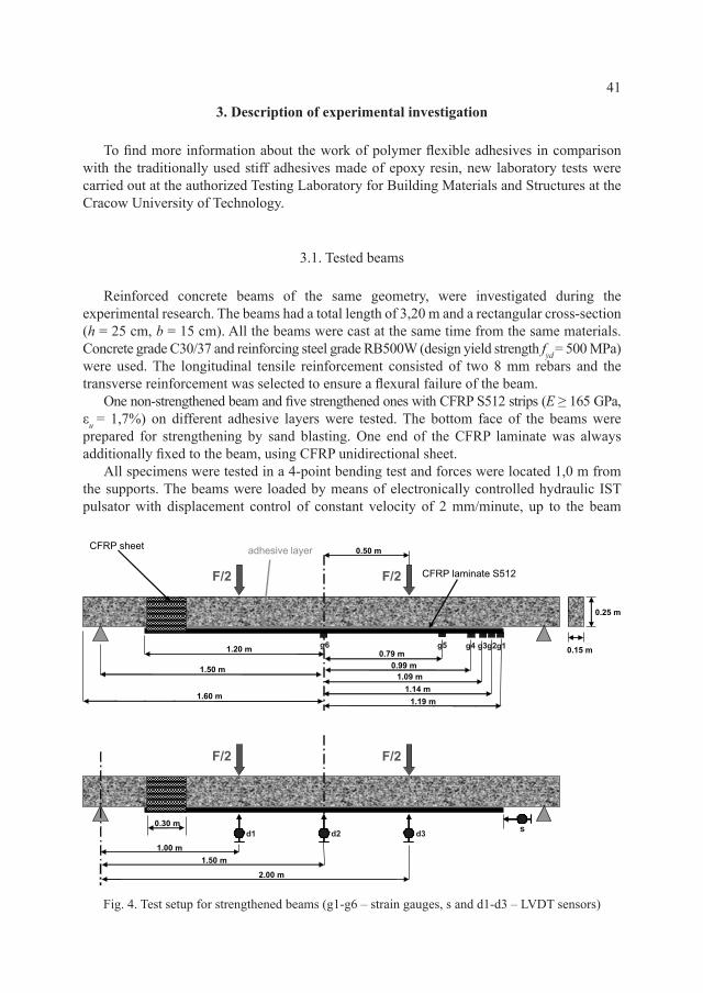
All specimens were tested in a 4-point bending test and forces were located 1,0 m from the supports. The beams were loaded by means of electronically controlled hydraulic IST pulsator with displacement control of constant velocity of 2 mm/minute, up to the beam
Fig. 4. Test setup for strengthened beams (g1-g6 – strain gauges, s and d1-d3 – LVDT sensors)
42
failure. Continuous data acquisition (the values of time, external force, deflections, CFRP strain and end slip) was carried out with the electronic HBM devices connected to a PC. The deflections were measured with three LVDT gauges located at the midspan of the beam and under the load forces. The CFRP laminate strains were measured at one half of the laminate, not fixed on its end, with foil electric resistance strain gauges. The scheme of a strengthened beam and measurement points are presented in Fig. 4.
3.2. Characteristics of adhesive materials used
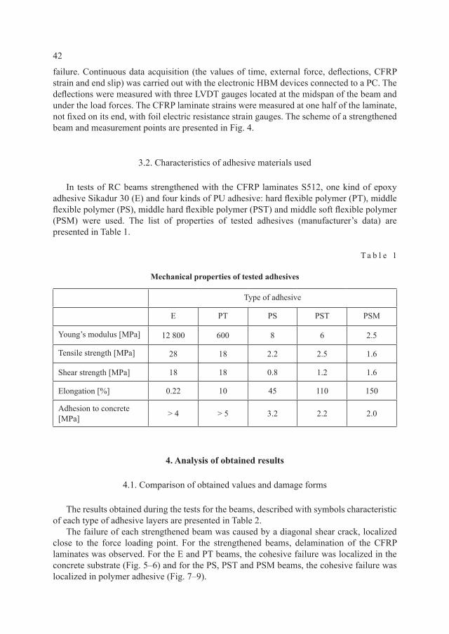
In tests of RC beams strengthened with the CFRP laminates S512, one kind of epoxy adhesive Sikadur 30 (E) and four kinds of PU adhesive: hard flexible polymer (PT), middle flexible polymer (PS), middle hard flexible polymer (PST) and middle soft flexible polymer (PSM) were used. The list of properties of tested adhesives (manufacturer’s data) are presented in Table 1.
T a b l e 1
Mechanical properties of tested adhesives
Type of adhesive
E PT PS PST PSM
Young’s modulus [MPa] 12 800 600 8 6 2.5
Tensile strength [MPa] 28 18 2.2 2.5 1.6
Shear strength [MPa] 18 18 0.8 1.2 1.6
Elongation [%] 0.22 10 45 110 150
Adhesion to concrete [MPa] > 4 > 5 3.2 2.2 2.0
4. Analysis of obtained results
4.1. Comparison of obtained values and damage forms
The results obtained during the tests for the beams, described with symbols characteristic of each type of adhesive layers are presented in Table 2.
The failure of each strengthened beam was caused by a diagonal shear crack, localized close to the force loading point. For the strengthened beams, delamination of the CFRP laminates was observed. For the E and PT beams, the cohesive failure was localized in the concrete substrate (Fig. 5–6) and for the PS, PST and PSM beams, the cohesive failure was localized in polymer adhesive (Fig. 7–9).

43
In the case of the E, PS and PST, beams failures in the form of slip occurred at the laminate parts protected against debonding from its end, using CFRP sheets. In the case of the PT and PSM beams, failures occurred at the free part of laminates (Table 2). Protection was used to assure debonding failure at the site of the beam with strain gauges, but the stiffening effect caused an unexpected form of failure.
T a b l e 2
Maximum force, displacement and deformation energy of each tested beam
Type of tested beam
RC E PT PS PST PSM
Max. force Fmax [kN] 25.6 59.7 65.5 64.7 54.4 48.7
Displacement at Fmax [mm] 30.0 33.9 37.4 28.6 29.9 29.1
Deformation energy – eq.
(1) W[1 J = 1 Nm]
629 1245 1461 1133 1065 942
Energy ratio[–]
WRC/WE0.50
WE/WE1
WPT/WE1.17
WPS/WE0.91
WPST/WE0.85
WPSM/WE0.75
Failure modeyielding of reinforcing
bars
delamination at fixed end
delamination at free end
delamination at fixed end
delamination at fixed end
delamination at free end
Fig. 5. Damages of beam (E) strengthened with CFRP bonded on epoxy adhesive
Fig. 6. Damages of beam (PT) strengthened with CFRP bonded on polymer adhesive

44
Fig. 7. Damages of beam (PS) strengthened with CFRP bonded on polymer adhesive
Fig. 8. Damages of beam (PST) strengthened with CFRP bonded on polymer adhesive
Fig. 9. Damages of beam (PSM) strengthened with CFRP bonded on polymer adhesive
4.2. Comparison of measurements
The diagram presenting vertical displacements of beams (measured at point d2 – Fig. 4) versus loading force (Fig. 10) enables a comparison of the work of the maximum force (deformation energy), calculated according to equation (1). The characteristic values of the curves are compared in Table 2.
maxdisplacement _ _
0
at F
W Fdy= ∫ (1)
where:F – loading force changing from 0 to Fmax,y – deflection (vertical displacement).
Polymer adhesives PT and PS assure a higher value of maximum force than epoxy ones (E) and comparable values of deformation energy indicate that polymer flexible adhesives (PT and PS) are as efficient as epoxy resin adhesives. Polymer adhesives PST and PSM are of a slightly worse parameters than adhesives E, PT and PS.

45
Fig. 10. Force-displacement curves of tested beams
The charts of CFRP end slips (measured at point s – see Fig. 4) versus applied load for the strengthened beams are given in Fig. 11. The occurrence of a much higher CFRP end slip is proportional to elongation and inversely proportional to stiffness (Young’s modulus) of adhesives (Table 1). The curves of CFRP slip, characteristic of the tested adhesives, confirm that flexible adhesives deform significantly along all bonding surface, even if the load is low. As shown in the chart, for beam E the strip’s end slip was practically associated with the loss of beam capacity (CFRP debonding). For all the beams strengthened with polymer joints, the end slip was noticeable, but did not involve direct loss of beam capacity. Even with the stiffest of the polymer joints used (beam PT), where the slip of CFRP laminate did not occur until the final phase of the test, flexibility of the adhesive layer helped to increase the scope of the beam work in relation to the stiff joint (beam E). The adhesive used in the PSM beam proved to be so soft that an increase of the end slip was observed from the very beginning of the test, and in the final stage of the test, the strip end displacement was so big that a measuring disturbance occurred as a result of sensor tip drifting.
The graphic comparisons of the CFRP laminate strain distribution measured at force level 40 kN is presented in Fig. 12 (diagrams concern half of the length of the laminate and the distance was measured out from the midspan of the beam). Strains were measured at points g1, g2, g3, g4, g5, g6 located on the axis of the CFRP laminate – distances between the points are shown in Fig. 4. The discontinuity of the graph for the PT beam results from damage to the strain gauge g3, located 11 cm from the strip end.
This graph shows that applying flexible polymer adhesives in FRP strengthening systems results in more uniform CFRP strain distribution along its length in relation to stiff (epoxy) adhesive. In the case of the epoxy bond, the end of the strip is practically unloaded.
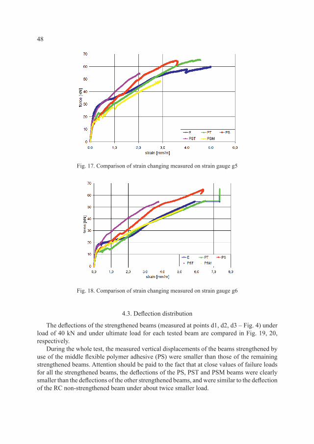
The graphic comparisons of the CFRP laminate strain changing with the load level are presented in Fig. 13–18. These graphs show that applying flexible polymer adhesives in FRP strengthening systems results in a more regular CFRP strain distribution with load level changing in relation to the stiff (epoxy) adhesive. Generally, strain distributions of CFRP laminates bonded on flexible polymer adhesives are comparable to the distribution obtained for the stiff epoxy adhesive classically used.

46
Fig. 11. Force-slip curves of the CFRP end obtained on strengthened beams in scale up to 3.5 mm and up to 1.0 mm
Fig. 12. Distribution of CFRP strain along its length obtained on reinforced beams under loading force F = 40 kN
Fig. 13. Comparison of strain changing measured on strain gauge g1

47
Fig. 14. Comparison of strain changing measured on strain gauge g2
Fig. 15. Comparison of strain changing measured on strain gauge g3
Fig. 16. Comparison of strain changing measured on strain gauge g4
48
Fig. 17. Comparison of strain changing measured on strain gauge g5
Fig. 18. Comparison of strain changing measured on strain gauge g6
4.3. Deflection distribution
The deflections of the strengthened beams (measured at points d1, d2, d3 – Fig. 4) under load of 40 kN and under ultimate load for each tested beam are compared in Fig. 19, 20, respectively.
During the whole test, the measured vertical displacements of the beams strengthened by use of the middle flexible polymer adhesive (PS) were smaller than those of the remaining strengthened beams. Attention should be paid to the fact that at close values of failure loads for all the strengthened beams, the deflections of the PS, PST and PSM beams were clearly smaller than the deflections of the other strengthened beams, and were similar to the deflection of the RC non-strengthened beam under about twice smaller load.

49
Fig. 19. Comparison of deflections of tested beams under load of 40 kN
Fig. 20. Comparison of deflections of tested beams under ultimate load
5. Analysis of obtained results
5.1. Focus on stress concentration generated by a crack
Directly in the place of crack appearance (Fig. 21) a new state of tension stress σCFRP in a CFRP laminate (strip) is generated, caused by a shear component τ and a debonding component σn. The value of tension stress can be calculated using equation (2).
2 2
CFRP nσ = σ + τ (2)
Additionally, the stress concentration phenomenon [3–4, 7] occurs in the debonded part of CFRP laminate, caused by the action of shear and normal stress concentrations, directly under the crack space (Fig. 21). Thus in reference to equation (2), the tension stress level is much higher than in the laminate joined to a concrete substrate.

50
Fig. 21. Shear and normal stress concentration in a CFRP laminate under crack
5.2. Redistribution of stress after crack appearance
Moreover, the high level of tensile stress in CFRP laminate derives from the redistribution of tensile stress in a working cross-section after crack appearance. Tensile forces F, calculated according to equation (3), are always in the state of balance before and after crack appearance, which is illustrated in Fig. 22. Before crack appearance (Fig. 22a), the resultant tensile force Ft in the tension zone is balanced by a sum of force components acting in structural materials: concrete FC, epoxy adhesive FA
epoxy and CFRP laminate FCFRP – equation (4).
F E A A= ⋅ε ⋅ = σ ⋅ (3)
epoxyCFRP
CFRPpolymer
CFRP
C A
t
A
F F FF F
F F
+ +
= +
(4)
where:E – Young’s modulus,e – strain, A – working cross-section of material under tension.
After crack appearance in the structure with stiff epoxy adhesive (Fig. 22b), the resultant tensile force Ft in the tension zone is balanced only by CFRP laminate FCFRP – equation (4), because stiff adhesive cracks in a brittle way almost at the same time as concrete, thus FCFRP has to be higher. On the other hand, if a flexible polymer adhesive is applied (Fig. 22c), the resultant tensile force Ft in the tension zone is balanced by a sum of force in polymer adhesive FA
polymer and in CFRP laminate FCFRP – equation (4). Tensile force in polymer FApolymer
still appears after cracking because a flexible adhesive layer reduces stress concentrations [3, 4] and protects CFRP laminate against the notch effect during debonding (Fig. 3, 21).

51
Fig. 22. Comparison of the tensile force balance in the tension zones for strengthened structures: a) before crack appearance (epoxy adhesive), b) after crack appearance (epoxy adhesive) and c) after
crack appearance (polymer adhesive)
5.3. Deflection reduction in the case of flexible polymer adhesive application
The observed reduction of beams deflection (Fig. 19, 20) in the case of flexible polymer adhesive (PS) application, is caused by protection against an increase of tensile stress σCFRP in CFRP laminate in the place of cracking. Because CFRP deformation ∆l is proportional to tensile stress σCFRP, the lower stress in the CFRP laminate is the lower is the CFRP deformation and thus lower deflection of strengthened beams.
In the case of stiff adhesive, many wide cracks with high stress concentration appear, thus the sum of the CFRP local deformations ∆l is higher than in the case of the flexible adhesive. On the other hand, the slips of CFRP ends are higher in the case of the flexible adhesive than in the case of stiff one. Comparing deflections for the same load (Fig. 19) of CFRP bonded on adhesives E and PS, it can be found that the E deflection is almost 1.5 higher than the PS deflection. Because the total elongation of the beam bottom is the sum of the local deformations (Σ∆l) and the sum of the slips (s) on both ends, and it is proportional to the deflection, the total elongation of CFRP bonded on a flexible adhesive is lower than the total elongation of CFRP bonded on a stiff adhesive.

52
6. Conclusions
It is commonly expected, taking a more flexible adhesive into consideration, that a higher slip of CFRP laminate should cause a higher value of beam deflection. Unexpectedly, the deflection of the PS beam (in the whole measured range) was clearly smaller than the deflections of other strengthened beams and the ultimate deflections of PS, PST, PSM beams were similar to the deflection of the RC non-strengthened beam under about twice smaller load. It was an effect of protection against an increase of tensile stress σ in CFRP laminate in the place of cracking. In the case of a stiff adhesive, many wide cracks with high stress concentration appear, thus the sum of the CFRP local deformations is higher than in the case of a flexible adhesive. Moreover, in the case of a flexible adhesive, cracks do not go through ductile polymer but are stopped in it and stress redistribution occurring in the adhesive layer allows for even distribution of load to the CFRP laminate.
The new approach to strengthening of RC beams with CFRP laminates using polymer flexible adhesives is innovative and opens a new branch in research analysis. It is obvious that a lot of tests on such adhesives have to be carried out to also check durability and rheological properties of the proposed system. The obtained results raise the authors’ hopes that solutions with application of polymer flexible adhesives will enable an increase in the efficiency of FRP in strengthening methods in the near future.
R e f e r e n c e s
[1] Derkowski W., Kwiecień A., Zając B., Comparison of CFRP strengthening efficiency of bent RC elements using stiff and flexible adhesives, 3rd International fib Congress and PCI Convention, Washington D.C., USA, June 2010.
[2] Cognard P., Technical Characteristics and Testing Methods for Adhesives and Sealants, Adhesives and Sealants Basic Concepts and High Tech Bonding, V. 1, Elsevier, 2005.
[3] Kwiecień A., Polymer flexible joints – an innovative repair system protecting cracked masonries against stress concentrations, Proceedings of Protection of Historical Build-ings, PROHITECH 09, V.2, 2009.
[4] Fitton M.D., Broughton J.G., Variable modulus adhesives: an approach to optimized joint performance, International Journal of Adhesion & Adhesives 25, 2005.
[5] Shrive N.G., Reda Taha M.M., Masia M.J., Restoration and strengthening with fiber reinforced polymers: issues to consider, Proceedings of 4th International Seminar on Structural Analysis of Historical Constructions., V. 2, 2004.
[6] Kwiecień A., Bonding of CFRP composites to structure using flexible polymer joint (in Polish), Zeszyty Naukowe Politechniki Łódzkiej, Budownictwo, Nr 55, 993, 2006.
[7] Buyukozturk O., Gunes O., Karaca E., Progress on understanding debonding problems in reinforced concrete and steel members strengthened using FRP composites, Construc-tion and Building Materials 18, 2004.