Three-layer piezoelectrets from fluorinated ethylene-propylene (FEP) copolymer films
7
Appl Phys A (2011) 103: 455–461 DOI 10.1007/s00339-010-6008-2 Three-layer piezoelectrets from fluorinated ethylene-propylene (FEP) copolymer films Peng Fang · Feipeng Wang · Werner Wirges · Reimund Gerhard · Heitor Cury Basso Received: 27 May 2010 / Accepted: 5 August 2010 / Published online: 31 August 2010 © Springer-Verlag 2010 Abstract A process for preparing three-layer piezoelectrets from fluorinated ethylene-propylene (FEP) copolymer films is introduced. Samples are made from commercial FEP films by means of laser cutting, laser bonding, electrode evaporation, and high-field poling. The observed dielectric- resonance spectra demonstrate the piezoelectricity of the FEP sandwiches. Piezoelectric d 33 coefficients up to a few hundred pC/N are achieved. Charging at elevated tempera- tures can increase the thermal stability of the piezoelectrets. Isothermal experiments for approximately 15 min demon- strate that samples charged at 140°C keep their piezoelectric activity up to at least 120°C and retain 70% of their initial d 33 even at 130°C. Acoustical measurements show a rela- tively flat frequency response in the range between 300 Hz and 20 kHz. 1 Introduction Polymer ferroelectrets are attractive materials for sensors and actuators with specific and sometimes unusual prop- erty combinations [1]. In comparison to crystals or ceramics, piezoelectric polymers show a number of advantages, such as low weight, flexibility, adaptability to various shapes, P. Fang ( ) · F. Wang · W. Wirges · R. Gerhard Applied Condensed-Matter Physics, Institute of Physics and Astronomy, Faculty of Science, University of Potsdam, Karl-Liebknecht-Strasse 24-25, 14476 Potsdam-Golm, Germany e-mail: [email protected] Fax: +49-331-9775494 H.C. Basso Department of Electrical Engineering, São Carlos School of Engineering, University of São Paulo, Avenida Trabalhador Sãocarlense 400, 13566-590 São Carlos, SP, Brazil low acoustic impedance, easy handling, etc. For more than four decades, ferroelectrics based on polar polymers such as β -phase polyvinylidene fluoride (β -PVDF) and some of its copolymers with trifluoroethylene (P(VDF-TrFE)) were under development and investigation [2–4]. More re- cently, ferroelectrets from non-polar polymers came into the focus of applied science. Cellular polymer-ferroelectret films from polypropylene (PP), polyethylene terephthalate (PET), cyclo-olefin copolymers (COCs), and polyethylene naphthalate (PEN) were developed and investigated in view of their potential piezoelectric applications [5–9]. In addition, three-layer piezoelectrets from FEP/porous- polytetrafluoroethylene (p-PTFE)/FEP have been reported [10, 11]. There are, however, still shortcomings that limit the use of the present polymer ferroelectrics and ferroelectrets. For example, β -PVDF films show relatively small stable d 33 coefficients of only about 20 pC/N and cannot be utilized at temperatures higher than 80°C [3]. PP ferroelectrets may exhibit d 33 coefficients of 600 pC/N and more, but their op- erating temperature cannot be much higher than 60°C. PET, COC, and PEN ferroelectrets show slightly better d 33 stabil- ities, but usually at the price of smaller d 33 values [5–9]. The properties of ferroelectrets strongly depend on the cellular morphology, i.e. on the size and the distribution of the voids, and the controlled preparation of an optimized cellular structure is still a challenge [12]. Recently, FEP piezoelectrets with tubular channels have been proposed and demonstrated [13]. Because of the excellent thermal charge stability of FEP, a maximum operating temperature of 130°C was achieved. On the other hand, this concept requires a lamination process carried out at approximately 300°C, which increases the fabrication cost. Thus, an al- ternative process for preparing three-layer FEP sandwich piezoelectrets [14] has been developed. Further details and
Transcript of Three-layer piezoelectrets from fluorinated ethylene-propylene (FEP) copolymer films
Appl Phys A (2011) 103: 455–461DOI 10.1007/s00339-010-6008-2
Three-layer piezoelectrets from fluorinated ethylene-propylene(FEP) copolymer films
Peng Fang · Feipeng Wang · Werner Wirges ·Reimund Gerhard · Heitor Cury Basso
Received: 27 May 2010 / Accepted: 5 August 2010 / Published online: 31 August 2010© Springer-Verlag 2010
Abstract A process for preparing three-layer piezoelectretsfrom fluorinated ethylene-propylene (FEP) copolymer filmsis introduced. Samples are made from commercial FEPfilms by means of laser cutting, laser bonding, electrodeevaporation, and high-field poling. The observed dielectric-resonance spectra demonstrate the piezoelectricity of theFEP sandwiches. Piezoelectric d33 coefficients up to a fewhundred pC/N are achieved. Charging at elevated tempera-tures can increase the thermal stability of the piezoelectrets.Isothermal experiments for approximately 15 min demon-strate that samples charged at 140°C keep their piezoelectricactivity up to at least 120°C and retain 70% of their initiald33 even at 130°C. Acoustical measurements show a rela-tively flat frequency response in the range between 300 Hzand 20 kHz.
1 Introduction
Polymer ferroelectrets are attractive materials for sensorsand actuators with specific and sometimes unusual prop-erty combinations [1]. In comparison to crystals or ceramics,piezoelectric polymers show a number of advantages, suchas low weight, flexibility, adaptability to various shapes,
P. Fang (�) · F. Wang · W. Wirges · R. GerhardApplied Condensed-Matter Physics, Institute of Physics andAstronomy, Faculty of Science, University of Potsdam,Karl-Liebknecht-Strasse 24-25, 14476 Potsdam-Golm, Germanye-mail: [email protected]: +49-331-9775494
H.C. BassoDepartment of Electrical Engineering, São Carlos Schoolof Engineering, University of São Paulo, Avenida TrabalhadorSãocarlense 400, 13566-590 São Carlos, SP, Brazil
low acoustic impedance, easy handling, etc. For more thanfour decades, ferroelectrics based on polar polymers suchas β-phase polyvinylidene fluoride (β-PVDF) and someof its copolymers with trifluoroethylene (P(VDF-TrFE))were under development and investigation [2–4]. More re-cently, ferroelectrets from non-polar polymers came intothe focus of applied science. Cellular polymer-ferroelectretfilms from polypropylene (PP), polyethylene terephthalate(PET), cyclo-olefin copolymers (COCs), and polyethylenenaphthalate (PEN) were developed and investigated inview of their potential piezoelectric applications [5–9].In addition, three-layer piezoelectrets from FEP/porous-polytetrafluoroethylene (p-PTFE)/FEP have been reported[10, 11]. There are, however, still shortcomings that limit theuse of the present polymer ferroelectrics and ferroelectrets.For example, β-PVDF films show relatively small stable d33
coefficients of only about 20 pC/N and cannot be utilizedat temperatures higher than 80°C [3]. PP ferroelectrets mayexhibit d33 coefficients of 600 pC/N and more, but their op-erating temperature cannot be much higher than 60°C. PET,COC, and PEN ferroelectrets show slightly better d33 stabil-ities, but usually at the price of smaller d33 values [5–9].
The properties of ferroelectrets strongly depend on thecellular morphology, i.e. on the size and the distribution ofthe voids, and the controlled preparation of an optimizedcellular structure is still a challenge [12]. Recently, FEPpiezoelectrets with tubular channels have been proposedand demonstrated [13]. Because of the excellent thermalcharge stability of FEP, a maximum operating temperatureof 130°C was achieved. On the other hand, this conceptrequires a lamination process carried out at approximately300°C, which increases the fabrication cost. Thus, an al-ternative process for preparing three-layer FEP sandwichpiezoelectrets [14] has been developed. Further details and
456 P. Fang et al.
typical experimental results will be presented and discussedin the following.
2 Sample preparation
We started with commercially available DuPont Teflon®
FEP films of 50 µm thickness. As depicted in Fig. 1(a)(left), an FEP mesh was sandwiched between two uniformFEP films that had been metalized with 50 nm thick alu-minum electrodes on their respective outer surfaces. Themesh had been prepared by means of laser cutting (Ver-saLaser, F. Huhn & Sohn GmbH). It contained a regular gridof square holes (3 × 3 mm2) separated by 1 mm wide FEPstripes. The overall area of the three-layer sandwich with6 × 6 holes was 29 × 29 mm2. For internal charging (pol-ing), a DC voltage was applied to the electrodes, as depictedin Fig. 1(a) (right). After poling, the three layers were locallybonded: A laser beam (VersaLaser, F. Huhn & Sohn GmbH)with a diameter of 0.1 mm was applied at selected points onthe stripes of the grid, with a separation of 2 mm, as shownin Fig. 1(b). The laser beam melted the FEP locally withina very short time. When the laser moved away, the moltenpolymer material in adjacent layers solidified jointly, so thatthe FEP grid and the films were fused. With this versatileprocess, there are practically no limits to the sample sizeand shape. The concept of the three-layer ferroelectret sand-wich is similar to that of the electret condenser microphoneintroduced in the 1960s [15]. Due to their structure, three-layer ferroelectrets are suitable for the detection of relativelysmall localized mechanical stresses and for sound emissionand reception.
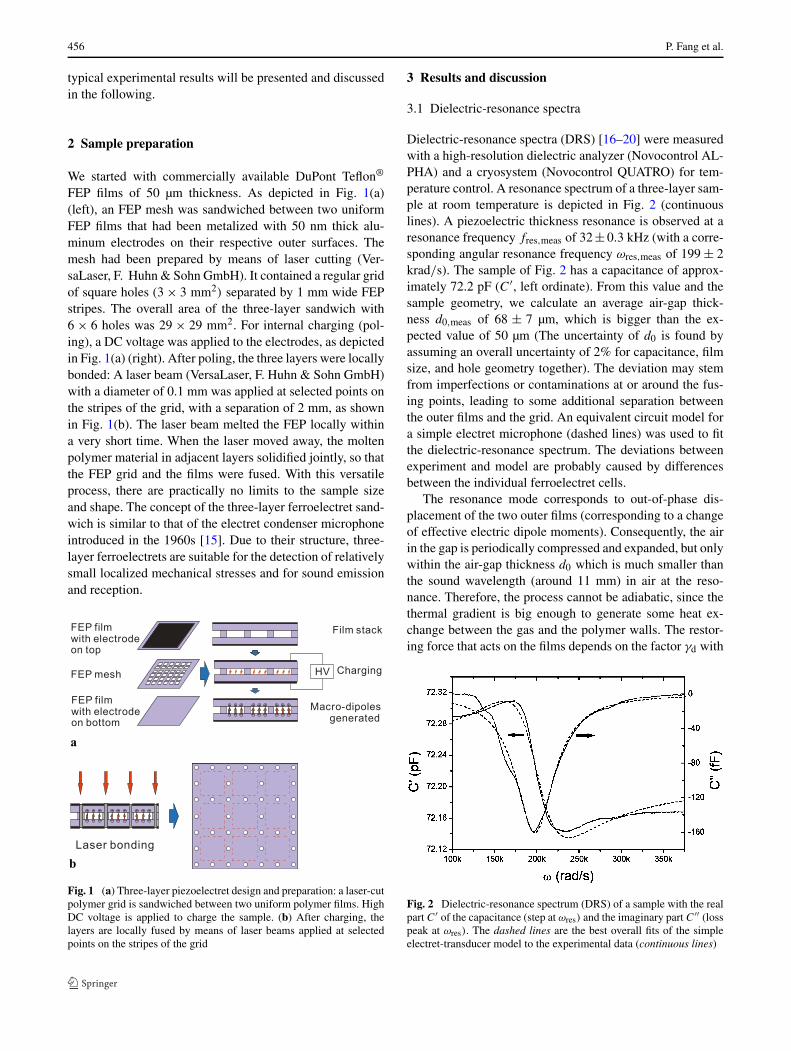
Fig. 1 (a) Three-layer piezoelectret design and preparation: a laser-cutpolymer grid is sandwiched between two uniform polymer films. HighDC voltage is applied to charge the sample. (b) After charging, thelayers are locally fused by means of laser beams applied at selectedpoints on the stripes of the grid
3 Results and discussion
3.1 Dielectric-resonance spectra
Dielectric-resonance spectra (DRS) [16–20] were measuredwith a high-resolution dielectric analyzer (Novocontrol AL-PHA) and a cryosystem (Novocontrol QUATRO) for tem-perature control. A resonance spectrum of a three-layer sam-ple at room temperature is depicted in Fig. 2 (continuouslines). A piezoelectric thickness resonance is observed at aresonance frequency fres,meas of 32 ± 0.3 kHz (with a corre-sponding angular resonance frequency ωres,meas of 199 ± 2krad/s). The sample of Fig. 2 has a capacitance of approx-imately 72.2 pF (C′, left ordinate). From this value and thesample geometry, we calculate an average air-gap thick-ness d0,meas of 68 ± 7 µm, which is bigger than the ex-pected value of 50 µm (The uncertainty of d0 is found byassuming an overall uncertainty of 2% for capacitance, filmsize, and hole geometry together). The deviation may stemfrom imperfections or contaminations at or around the fus-ing points, leading to some additional separation betweenthe outer films and the grid. An equivalent circuit model fora simple electret microphone (dashed lines) was used to fitthe dielectric-resonance spectrum. The deviations betweenexperiment and model are probably caused by differencesbetween the individual ferroelectret cells.
The resonance mode corresponds to out-of-phase dis-placement of the two outer films (corresponding to a changeof effective electric dipole moments). Consequently, the airin the gap is periodically compressed and expanded, but onlywithin the air-gap thickness d0 which is much smaller thanthe sound wavelength (around 11 mm) in air at the reso-nance. Therefore, the process cannot be adiabatic, since thethermal gradient is big enough to generate some heat ex-change between the gas and the polymer walls. The restor-ing force that acts on the films depends on the factor γd with
Fig. 2 Dielectric-resonance spectrum (DRS) of a sample with the realpart C′ of the capacitance (step at ωres) and the imaginary part C′′ (losspeak at ωres). The dashed lines are the best overall fits of the simpleelectret-transducer model to the experimental data (continuous lines)

Three-layer piezoelectrets from fluorinated ethylene-propylene (FEP) copolymer films 457
Fig. 3 Calculated resonance frequency versus air-gap thickness d0 atthe two limiting values of the factor γd (dash-dotted lines). The exper-imental value ωres,meas and d0,meas are also shown. The horizontal barindicates the scatter and the uncertainty of d0,meas. The bold part of thebar shows the coincidence region between the experimental results andthe model calculations
an upper limit of 1.4 for an adiabatic process and a lowerlimit of 1 for an isothermal process. A more precise estimatefor γd is discussed elsewhere [21]. In the present context,γd is an adjustable parameter (1 ≤ γd ≤ 1.4). The resonancefrequency ωres of each cell, composed of two square plateswith fixed boundaries and an air gap, is
ωres =√
ω21 + γd
κpneum
d0, (1)
where ω1 = 28.8 krad/s is the angular resonance fre-quency of the cell top and bottom plates in the fundamentalmode, calculated by means of a finite-element method, andγdκpneum/d0 is the contribution from the air in the gap, withκpneum = 1.86 × 10⁶ m−1. For the calculation of these pa-rameters, film density, film thickness, elastic modulus, Pois-son’s ratio [22], and air pressure (105 Pa) were taken intoaccount. The last term is inversely proportional to the air-gap thickness d0. Figure 3 shows the calculated resonancefrequency as a function of d0 for the two limiting values ofγd (dash-dotted lines), and the experimental value ωres,meas
vs. the measured range of d0,meas (horizontal bar). The boldpart of the bar indicates the range in which the ranges ofexperimental and the calculated values coincide.
3.2 Thermal properties
The dielectric-resonance spectra discussed in the last sec-tion were utilized to investigate the thermal properties ofthe samples. To this end, the samples were charged at roomtemperature (RT) or at the selected elevated temperatures of110 and 140°C, respectively. With charging at elevated tem-peratures, the charging voltage was switched off after the
sample had cooled down to RT. The temperature-dependentdielectric-resonance spectra were acquired by means of a so-called “short-term test” at progressively increasing tempera-tures: The sample was fixed in a sealed chamber and heatedto the preset temperature in a nitrogen flow at a heating rateof 2.2°C/min. The measurement of each spectrum (frequen-cies from 1 kHz to 1 MHz) took 15 min and was recordedas a function of frequency under nearly isothermal condi-tions (�Tmax = ±0.43°C) at the preset temperature. Then,the same sample was heated to the next temperature at thesame heating rate as before, and the corresponding spectrumwas recorded. The spectra were measured in a temperaturerange from 20 to 150°C at 10°C steps. The correspondingdielectric-loss spectra (imaginary capacitance C′′, only thefrequency range from 1 kHz to 100 kHz is shown) for sam-ples charged at room temperature, at 110°C, and at 140°Care show in Figs. 4(a), (b), and (c), respectively.
Dielectric resonance peaks are observed at frequenciesof 30.9, 49.0, and 52.5 kHz for the samples charged at RT,110°C, and 140°C, respectively. Piezoelectrets charged atelevated temperatures show higher resonance frequenciesfres than the one charged at RT. This behavior is probablycaused by the thermal treatment connected with the high-temperature charging and the subsequent cooling down ofthe FEP films. Because of this treatment, the sample shrankand became stiffer than before. As a result, the respectiveresonance frequencies increased.
The complex capacitance of a thin planar film near thethickness-extension (TE) mode is given by [16–18]
C̃TE(ω) = ε0ε33A
h
1
1 − k2t
tan(ω/4fres)ω/4fres
− iCloss, (2)
where the anti-resonance frequency fres and the complexelectromechanical coupling factor kt are expressed as
fres = 1
2h
√c33
ρ(3)
for a free-standing sample, or
fres = 1
4h
√c33
ρ(4)
for a sample that is completely fixed at one surface, and
kt ≈ d33
√c33
ε0ε33, (5)
respectively. Here, ε33 is the 33 component of the relative-permittivity tensor of the sample material, A is the area ofthe sample electrode, c33 is the elastic modulus, and h and ρ
are the thickness and density of the sample, respectively. Byfitting the dielectric spectra with the appropriate equations,several relevant quantities can be determined.

458 P. Fang et al.
Fig. 4 Temperature-frequency maps of the dielectric loss (imagi-nary capacitance C′′) for samples charged at (a) room temperature,(b) 110°C, and (c) 140°C
Fig. 5 Elastic modulus c33 for increasing temperatures on samplescharged at the indicated temperatures. The data were acquired in a“short-term test”, i.e. the samples were heated at each preset tempera-ture for 15 min. The lines are only for guiding the eyes
With increasing temperature, the dielectric-loss peaks de-crease due to the gradual loss of piezoelectricity (Fig. 4), andseveral other parameters change as well. Figure 5 shows thec33 modulus as a function of temperature. For the samplecharged at RT, c33 increases with increasing temperature.Because this sample did not undergo any prior annealing,the film shrinks upon heating. On the other hand, however,the films are fixed at the bonding points of the layer sys-tem. Therefore, they are subjected to more and more ten-sion, which increases the effective elastic c33 modulus. Theincrease of c33 stops at a temperature of 80°C, which isthe approximate value of the glass-transition temperature(Tg) of FEP. Above Tg, the films become soft, which low-ers c33. These two opposite effects (tension and softening)now probably compensate each other, so that c33 does not in-crease any further. The RT-charged samples do not show anydetectable dielectric resonance when treated at temperatureshigher than 100°C. For samples charged at elevated temper-atures, c33 decreases with increasing temperature, especiallyabove 80°C (Tg of FEP). Since these samples have been ther-mally treated during charging, there is no further shrinkageupon the second thermal treatment during the measurement.The films become softer, which is more obvious at temper-atures above Tg. Figure 6 shows the electromechanical cou-pling factor k33 as a function of temperature. For most sam-ples, the k33 values are found to be smaller than 0.06.
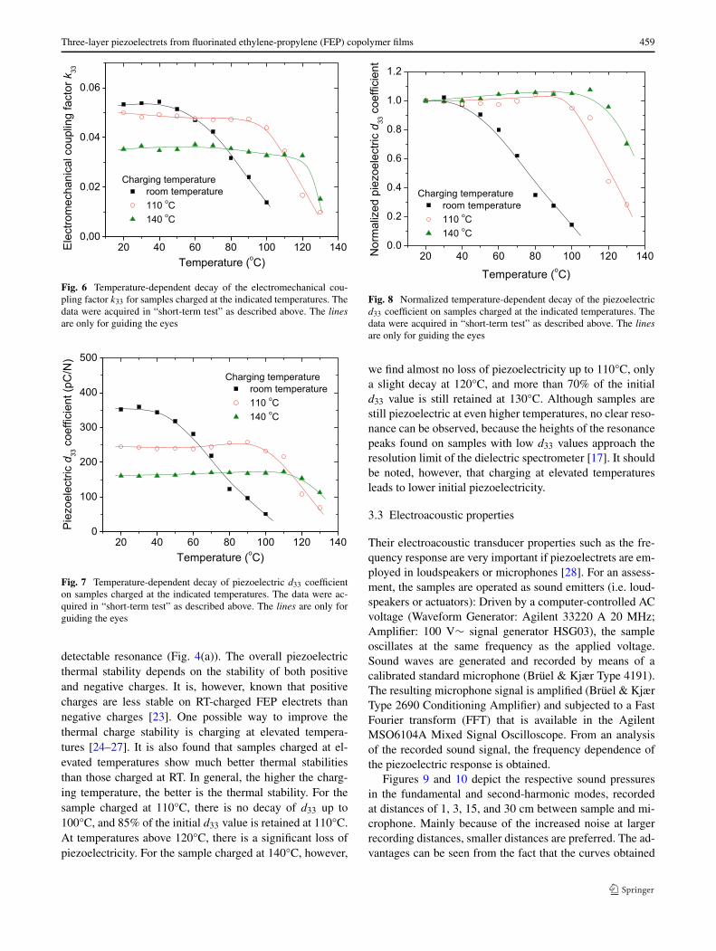
Figures 7 and 8 illustrate the thermal stability of thepiezoelectric d33 coefficient in absolute and in relativeterms, respectively. Samples may exhibit d33 values ashigh as 350 pC/N when charged at RT, but only 250 and160 pC/N when charged at 110 and 140°C, respectively.For the RT-charged sample, there is a significant and con-tinuous decay of d33, and its piezoelectricity is apparentlyalmost completely lost above 100°C, as there is no more
Three-layer piezoelectrets from fluorinated ethylene-propylene (FEP) copolymer films 459
Fig. 6 Temperature-dependent decay of the electromechanical cou-pling factor k33 for samples charged at the indicated temperatures. Thedata were acquired in “short-term test” as described above. The linesare only for guiding the eyes
Fig. 7 Temperature-dependent decay of piezoelectric d33 coefficienton samples charged at the indicated temperatures. The data were ac-quired in “short-term test” as described above. The lines are only forguiding the eyes
detectable resonance (Fig. 4(a)). The overall piezoelectricthermal stability depends on the stability of both positiveand negative charges. It is, however, known that positivecharges are less stable on RT-charged FEP electrets thannegative charges [23]. One possible way to improve thethermal charge stability is charging at elevated tempera-tures [24–27]. It is also found that samples charged at el-evated temperatures show much better thermal stabilitiesthan those charged at RT. In general, the higher the charg-ing temperature, the better is the thermal stability. For thesample charged at 110°C, there is no decay of d33 up to100°C, and 85% of the initial d33 value is retained at 110°C.At temperatures above 120°C, there is a significant loss ofpiezoelectricity. For the sample charged at 140°C, however,
Fig. 8 Normalized temperature-dependent decay of the piezoelectricd33 coefficient on samples charged at the indicated temperatures. Thedata were acquired in “short-term test” as described above. The linesare only for guiding the eyes
we find almost no loss of piezoelectricity up to 110°C, onlya slight decay at 120°C, and more than 70% of the initiald33 value is still retained at 130°C. Although samples arestill piezoelectric at even higher temperatures, no clear reso-nance can be observed, because the heights of the resonancepeaks found on samples with low d33 values approach theresolution limit of the dielectric spectrometer [17]. It shouldbe noted, however, that charging at elevated temperaturesleads to lower initial piezoelectricity.
3.3 Electroacoustic properties
Their electroacoustic transducer properties such as the fre-quency response are very important if piezoelectrets are em-ployed in loudspeakers or microphones [28]. For an assess-ment, the samples are operated as sound emitters (i.e. loud-speakers or actuators): Driven by a computer-controlled ACvoltage (Waveform Generator: Agilent 33220 A 20 MHz;Amplifier: 100 V∼ signal generator HSG03), the sampleoscillates at the same frequency as the applied voltage.Sound waves are generated and recorded by means of acalibrated standard microphone (Brüel & Kjær Type 4191).The resulting microphone signal is amplified (Brüel & KjærType 2690 Conditioning Amplifier) and subjected to a FastFourier transform (FFT) that is available in the AgilentMSO6104A Mixed Signal Oscilloscope. From an analysisof the recorded sound signal, the frequency dependence ofthe piezoelectric response is obtained.
Figures 9 and 10 depict the respective sound pressuresin the fundamental and second-harmonic modes, recordedat distances of 1, 3, 15, and 30 cm between sample and mi-crophone. Mainly because of the increased noise at largerrecording distances, smaller distances are preferred. The ad-vantages can be seen from the fact that the curves obtained
460 P. Fang et al.
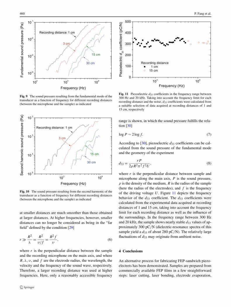
Fig. 9 The sound pressure resulting from the fundamental mode of thetransducer as a function of frequency for different recording distances(between the microphone and the sample) as indicated
Fig. 10 The sound pressure resulting from the second harmonic of thetransducer as a function of frequency for different recording distances(between the microphone and the sample) as indicated
at smaller distances are much smoother than those obtainedat larger distances. At higher frequencies, however, smallerdistances can no longer be considered as being in the “farfield” defined by the condition [29]
r � R2
λ= R2
υ/f= R2f
υ, (6)
where r is the perpendicular distance between the sampleand the recording microphone on the main axis, and whereR,λ,υ , and f are the electrode radius, the wavelength, thevelocity and the frequency of the sound wave, respectively.Therefore, a larger recording distance was used at higherfrequencies. Here, only a reasonably accessible frequency
Fig. 11 Piezoelectric d33 coefficients in the frequency range between300 Hz and 20 kHz. Taking into account the frequency limit for eachrecording distance and the noise, d33 coefficients were calculated froma suitable selection of data acquired at recording distances of 1 and15 cm, respectively
range is shown, in which the sound pressure fulfills the rela-tion [30]
logP ∼ 2 logf. (7)
According to [30], piezoelectric d33 coefficients can be cal-culated from the sound pressure of the fundamental modeand the geometry of the experiment
d33 = rP
2ρR2π2f 2U, (8)
where r is the perpendicular distance between sample andmicrophone along the main axis, P is the sound pressure,ρ is the density of the medium, R is the radius of the sample(here the radius of the electrodes), and f is the frequencyof the driving voltage U . Figure 11 depicts the frequencybehavior of the d33 coefficient. The d33 coefficients werecalculated from the experimental data acquired at recordingdistances of 1 and 15 cm, taking into account the frequencylimit for each recording distance as well as the influence ofthe surroundings. In the frequency range between 300 Hzand 20 kHz, the sample shows nearly stable d33 values of ap-proximately 300 pC/N (dielectric-resonance spectra of thissample yield a d33 of about 280 pC/N). The relatively largefluctuations of d33 may originate from ambient noise.
4 Conclusions
An alternative process for fabricating FEP-sandwich piezo-electrets has been demonstrated. Samples are prepared fromcommercially available FEP films in a few straightforwardsteps: laser cutting, laser bonding, electrode evaporation,

Three-layer piezoelectrets from fluorinated ethylene-propylene (FEP) copolymer films 461
and high-field poling (charging). Dielectric-resonance spec-troscopy (DRS) demonstrates the piezoelectricity of theFEP sandwiches. Piezoelectric d33 coefficients as high as350 pC/N are achieved by means of optimized structurepreparation and electric charging. The thermal stability ofthe piezoelectric response was investigated by means ofDRS as well. Samples were isothermally treated for 15 minat increasing temperatures from 20 to 130°C with 10°C in-terval. As expected, samples charged at suitable elevatedtemperatures show much better thermal stability. No decayof d33 up to at least 110°C is observed on samples charged at140°C. There is only a slight decay of d33 at 120°C in thesesamples, and they retain 70% of their initial piezoelectric-ity at 130°C. Electroacoustic measurements reveal a ratherflat frequency response in the range between 300 Hz and20 kHz.
Acknowledgements Funding from CAPES (Brazil) and DAAD(Germany) (PROBRAL No. D/08/11608) is gratefully acknowledged.The 2nd author (F.W.) thanks the DFG for providing a Research Fel-lowship (WA 2688/1-1) to him. Some of the equipment was co-fundedby the EU (EFRE program).
References
1. S. Bauer, R. Gerhard-Multhaupt, G.M. Sessler, Phys. Today 57(2),37 (2004)
2. H. Kawai, Jpn. J. Appl. Phys. 8, 975 (1969)3. G.M. Sessler, J. Acoust. Soc. Am. 70, 1596 (1981)4. F. Yao, C. Erol, K.G. Muralidhar, M.S. Geoff, Smart Mater. Struct.
15, 141 (2006)5. J. Lekkala, M. Paajanen, in Proceedings of the Tenth International
Symposium on Electrets, Delphi, Greece, 22–24 September 1999(IEEE Service Center, Piscataway, 1999), pp. 743–746
6. G.M. Sessler, J. Hillenbrand, Appl. Phys. Lett. 75, 3405 (1999)7. W. Wirges, M. Wegener, O. Voronina, L. Zirkel, R. Gerhard-
Multhaupt, Adv. Funct. Mater. 17, 324 (2007)8. E. Saarimäki, M. Paajanen, A.-M. Savijärvi, H. Minkkinen,
M. Wegener, O. Voronina, R. Schulze, W. Wirges, R. Gerhard-Multhaupt, IEEE Trans. Dielectr. Electr. Insul. 13, 973 (2006)
9. P. Fang, M. Wegener, W. Wirges, R. Gerhard, Appl. Phys. Lett.90, 192908 (2007)
10. Z. Hu, H. von Seggern, J. Appl. Phys. 99, 024102 (2006)11. S. Zhukov, H. von Seggern, J. Appl. Phys. 102, 044109 (2007)12. P. Fang, W. Wirges, M. Wegener, L. Zirkel, R. Gerhard,
e-Polymers 43 (2008)13. R.A.P. Altafim, X. Qiu, W. Wirges, R. Gerhard, R.A.C. Altafim,
H.C. Basso, W. Jenninger, J. Wagner, J. Appl. Phys. 106, 014106(2009)
14. H.C. Basso, R.A.P. Altafim, R.A.C. Altafim, A. Mellinger,P. Fang, W. Wirges, R. Gerhard, in Proceedings of the Annual Re-port Conference on Electrical Insulation and Dielectric Phenom-ena (CEIDP), Vancouver, Canada, 14–17 October 2007 (IEEEService Center, Piscataway, 2007), pp. 453–456
15. G.M. Sessler, J.E. West, J. Acoust. Soc. Am. 34, 1787 (1962)16. K. Omote, H. Ohigashi, K. Koga, J. Appl. Phys. 81, 2760 (1997)17. A. Mellinger, IEEE Trans. Dielectr. Electr. Insul. 10, 842 (2003)18. IEEE Standard on Piezoelectricity, ANSI/IEEE Std. 176-1987
(1987)19. W.P. Mason, Physical Acoustics, vol. I (Academic Press, New
York, 1967), Part A20. G.S. Neugeschwandtner, R. Schwoediauer, M. Vieytes, S. Bauer-
Gogonea, S. Bauer, J. Hillenbrand, R. Kressmann, G.M. Sessler,M. Paajanen, J. Lekkala, Appl. Phys. Lett. 77, 3827 (2000)
21. H.C. Basso, unpublished results22. DuPont FEP Information Bulletin. http://www2.dupont.com/
Teflon_Industrial/en_US/assets/downloads/h55007.pdf23. R. Kressmann, G.M. Sessler, P. Günther, Space-charge electrets,
in Electrets, vol. 2, 3rd edn., ed. by R. Gerhard-Multhaupt (Lapla-cian Press, Morgan Hill, 1999), pp. 1–40, Chap. 9
24. H. von Seggern, J.E. West, J. Appl. Phys. 55, 2754 (1984)25. J. van Turnhout, Thermally Stimulated Discharge of Polymer Elec-
trets (Elsevier, Amsterdam, 1975)26. M.M. Perlman, S. Unger, Appl. Phys. Lett. 24, 579 (1974)27. Z. Xia, H. Ding, G. Yang, T. Lu, X. Sun, IEEE Trans. Electr. Insul.
26, 35 (1991)28. M. Dansachmüller, I. Minev, P. Bartu, I. Graz, N. Arnold,
S. Bauer, Appl. Phys. Lett. 91, 222906 (2007) and referencestherein
29. M. Möser, Technische Akustik, 6th edn. (Springer, Heidelberg,2005)
30. R. Kressmann, J. Acoust. Soc. Am. 109, 1412 (2001)