Controlled Arrangement of Nanoparticle Arrays in Block-Copolymer Domains
12
Composite materials DOI: 10.1002/smll.200500474 Controlled Arrangement of Nanoparticle Arrays in Block-Copolymer Domains Agus Haryono and Wolfgang H. Binder* From the Contents 1. Introduction............. 601 2. Theory and Simulation ................................ 602 3. Interfacial Interactions ................................ 603 4. Control of Spatial Distribution.............. 605 5. Applications in Technology............... 608 6. Conclusions and Future Outlook.................... 610 Keywords: · block copolymers · microphase separation · nanoparticles · nanoscience · self-assembly Block copolymers form composite materials with metal and semiconducting nanoparticles, which exhibit many useful properties. 600 www.small-journal.com # 2006 Wiley-VCH Verlag GmbH & Co. KGaA, D-69451 Weinheim small 2006, 2, No. 5, 600 – 611 reviews A. Haryono and W. H. Binder
Transcript of Controlled Arrangement of Nanoparticle Arrays in Block-Copolymer Domains

Composite materials
DOI: 10.1002/smll.200500474
Controlled Arrangement of Nanoparticle Arrays inBlock-Copolymer DomainsAgus Haryono and Wolfgang H. Binder*
From the Contents
1. Introduction.............601
2. Theory and Simulation................................602
3. Interfacial Interactions................................603
4. Control of SpatialDistribution..............605
5. Applications inTechnology...............608
6. Conclusions and FutureOutlook....................610
Keywords:· block copolymers· microphase separation· nanoparticles· nanoscience· self-assembly
Block copolymers form composite materials with metal and semiconducting nanoparticles, which exhibit manyuseful properties.
600 www.small-journal.com � 2006 Wiley-VCH Verlag GmbH&Co. KGaA, D-69451 Weinheim small 2006, 2, No. 5, 600 – 611
reviews A. Haryono and W. H. Binder

This Review describes recent results on the precise spatial distributioncontrol of metal and semiconductor nanoparticles into domains ofmicrophase-separated block copolymers. Specific focus is directed towardsselective incorporation into a specific microphase of a block copolymer.Details on theoretical aspects concerning nanoparticle incorporation as wellas practical examples are given. Furthermore, examples on applications andtechnological aspects of the resulting nanoparticle/polymer nanocompositesare provided.
1. Introduction
Nanoscience is still searching for simple methods to ar-range nanosized objects by means of bottom-up processes.Self-assembly processes are the method of choice to effectthis goal, focusing on the tailoring of supramolecular and in-terfacial forces and interactions. In recent years the prepara-tion of various types of polymer–nanoparticle compositematerials has progressed significantly, thus putting the nano-particle/polymer interface in the limelight of assembly pro-cesses.[1] Composite structures on the nanometer lengthscale promise to be candidates for next-generation materi-als, developing many applications of nanocomposite-baseddevices.[2] Important in this endeavor is the incorporation ofnonpolymeric properties into a polymeric matrix, which canonly be achieved by the unique properties of nanoparticu-late structures. As one understands the basic principles,which determine the optical, electronic, and magnetic prop-erties of the resulting composites, the possibility of buildingordered arrays of nanoparticles inside of polymer matricesis the important key point to tune their properties withinthe nanocomposite.
It is already well known that nanoparticles possessunique, often size-dependent properties associated withmagnetic, photonic, chemical, and electrical behavior, whichare different from the properties in their respective bulkmaterials. Those properties can be controlled through theimmobilization and the assembly of nanoparticles on an ap-propriate substrate or in a suitable medium. Many effortshave been carried out to assemble metal nanoparticles invarious modes, for example, via template-directed methodsrelying on surfactants[3] or polymers.[4] The important factorin determining the stable incorporation of the nanoparticleswithin a block-copolymer (BCP) matrix mainly lies in thecompatibility of the nanoparticles with the block-copolymermicrostructures, which in turn can be controlled consideringthe symmetry of both the inclusion and the block-copolymerhost matrix. Thus surface modification of the nanoparticles(NPs) is necessary to stabilize them against aggregationwithin the BCP-matrix, which normally tends to attract thenanoparticles by one of the blocks of a block copolymerand repel it by the other block of the copolymer. The result-ing materials thus can accumulate the nanoparticles intoone microphase of a BCP, reflecting the pattern formed bythe respective microphase (see Figure 1a). If metal nanopar-
ticles can be incorporated or arranged only into one domainof a microphase-separated block copolymer, it is possible totransfer the microphase separation of the BCP into ordered
[*] Prof. Dr. W. H. BinderVienna University of TechnologyInstitute of Applied Synthetic ChemistryDivision of Macromolecular ChemistryGetreidemarkt 9/163/MC, 1060 Vienna (Austria)Fax: (+43) 1-58801-16299E-mail: [email protected]
Dr. A. HaryonoIndonesian Institute of Sciences (LIPI)Research Center for ChemistryPolymer Chemistry Group, Kawasan Puspiptek Serpong15314 Tangerang (Indonesia)andInstitute of Applied Synthetic ChemistryDivision Macromolecular ChemistryGetreidemarkt 9/163/MC, 1060 Vienna (Austria)
Figure 1. a) Assembly of NPs into microphase-separated A–B diblockcopoylmers (BCPs). b) Density functional theory (DFT) calculation oflarge (case 1) and small NPs (case 2). The NPs are either located atthe center of the A phase (case 1) or driven closer to the A–B inter-face (case 2).
small 2006, 2, No. 5, 600 – 611 � 2006 Wiley-VCH Verlag GmbH&Co. KGaA, D-69451 Weinheim 601
Nanoparticle Composite Synthesis with Block Copolymers

arrays of NP structures having a unique spatial distributionin the matrix polymers.
Microphase separation in pure block copolymers is awell-studied phenomenon producing morphologies by phaseseparation that are determined by the relative lengths of thepolymer blocks, ranging from spheres to lamellae, or inter-connected network morphologies.[5] The size of each blockof the polymer domain is determined by its overall chainlength, thus providing a wide range of self-organized nano-scale-level templates. Most importantly, microphase-separat-ed BCPs spontaneously self-assemble into regular arrays ofdomains whose size can be controlled from a few to severaltens of nanometers, and in turn can act as hosts for seques-tering nanoscopic inclusions of appropriate chemical affinityand geometry.[6] Thus, BCPs can be used as templates toprovide supramolecular control over the size, particle densi-ty, and spatial location of various inorganic nanoparticles.The ability to control the length and the spatial and orienta-tional organization of block-copolymer morphologies makesthese materials particularly attractive as scaffolds for engi-neering nanostructures. However, the mechanism of organi-zation and the degree of order of the nanoparticles insidethe block-copolymer phases still remains to be investigatedand established. In this Review, we will describe recent re-sults on the precise spatial distribution control of metal, andsemiconducting nanoparticles in microphase-separatedblock-copolymer domains.
2. Theory and Simulation
Theoretical and computer simulation investigations ofnanoparticle–polymer composites have revealed the detailedmechanisms responsible for the development of structureand physical properties. Huh et al.[7] performed latticeMonte Carlo simulations to examine the phase behavior ofnanoparticles in melted-block copolymer domains. The spa-tial distribution of nanoparticles can be tuned by the size,concentration, and the interfacial interaction of the particleswithin the matrix. As the nanoparticle concentration in-creased, the domain into which the nanoparticles were en-
riched was preferentially swelled and subsequently inducedmicrophase transitions to cylinders and then to the disor-dered state, additionally reducing the order/disorder transi-tion temperature. The microphase transition is more pro-nounced if the nanoparticle size is comparable to the radiusof gyration of the minority block within the A–B diblockBCP and displays a strong attraction to this block. Largernanoparticles assembled into a particle-rich region at highconcentration.
Thompson et al.[8a] have studied A–B block copolymer–nanoparticle composites using a combination of self-consis-tent field theory (SCFT) for the block copolymer and densi-ty functional theory (DFT) for the nanoparticles (Fig-ure 1b). In order to simplify the effect between the blockchains and the nanoparticles, they set the enthalphic interac-tion Flory–Huggins parameter of the particle P to cAP=0,thus treating the particles as identical to the A-block phase(enthalphic interaction Flory–Huggins parameter cAP=0)and repelling it by the B-block phase (cBP=cBA=cAB), caus-ing the particles to preferentially localize in the A domains.They found that larger nanoparticles located at the centerof the preferred copolymer domain. Smaller nanoparticlesare driven nearer to the A–B interface due to dominationof the translational energy of the NPs in relation to the re-duced chain-stretching of the A chains. The specific mor-phology of the nanocomposite depended not only on theblock-copolymer architecture, but also on parameters suchas the size and volume fraction of the particles. Diblock co-polymer melts in the lamellar phase with added sphericalnanoparticles that have an affinity for one particular blockwere predicted to have a lower tensile modulus than a purediblock-copolymer system.[8b] This resulted in swelling of thelamellar domain by the nanoparticles and the displacementof macromolecules by the elastic inert fillers (nanoparti-cles).
Another simulation by Wang et al.[9] performed with lat-tice Monte Carlo simulations has examined the position of asingle spherical or cubic nanoparticle within lamellaeformed by a symmetrical A–B diblock copolymer withequal interactions to both blocks. Both small and largenanoparticles were preferentially located at the copolymer
Wolfgang H. Binder is currently associateprofessor of chemistry at the Vienna Uni-versity of Technology. After finishing hisPh.D. studies in organic carbohydratechemistry from the University of Vienna(Austria) with Prof. W. Schmid (1995) heworked as a postdoctoral researcherwith Prof. F. M. Menger on combinatorialpolymer chemistry, and subsequentlythen with Prof. J. Mulzer (University ofVienna) in total organic synthesis. Since2004, he has been associate professorat the University of Technology leading a
group in polymer chemistry. His current research interests are cen-tered on macromolecular synthesis, nanotechnology, and nanoparti-cles, with a focus on block copolymers, self-assembled monolayers,supramolecular chemistry, and membranes.
Agus Haryono was born in 1969. He re-ceived his B.S. degree from Waseda Uni-versity (Japan) in 1994 and obtained aPh.D. in Applied Chemistry in 1999under the supervision of Prof. E. Tsuchi-da for work on oxidative polymerizationsof aromatic compounds. He then spentthree years doing postdoctoral work atthe National Institute of Advanced Indus-trial Science and Technology (AIST) inTsukuba, developing polymeric self-as-sembled monolayers. He joined the In-donesian Institute of Sciences (LIPI) in
2002 and is currently leading the Polymer Chemistry Group at the Re-search Center for Chemistry (LIPI) in Serpong (Indonesia). He is cur-rently carrying out postdoctoral research in the group of Prof. Binderat the Vienna University of Technology, studying the interaction be-tween nanoparticles and block-copolymer domains.
602 www.small-journal.com � 2006 Wiley-VCH Verlag GmbH&Co. KGaA, D-69451 Weinheim small 2006, 2, No. 5, 600 – 611
reviews A. Haryono and W. H. Binder

interface without disturbance of the lamellar structure. Theshape of the NPs did not have a significant influence on theparticle distribution. Small NPs that preferred block A ofthe block copolymer were preferentially located within do-main A. Lee et al.[10] also studied nanocomposites confinedbetween the walls using SCFT. They concluded that a per-pendicular or parallel orientation of the lamellae was prefer-red, depending on the nanoparticle concentration, size, andstrength of the interaction with the copolymers or walls.
Schultz et al.[11] studied discontinuous molecular dynam-ics (DMD) simulations of block copolymer–nanoparticlecomposites. Thus, NPs interacting with neither blocks A orB tend to localize at the A–B interface, whereas nanoparti-cles that repel block A tend to localize in domain B. Thespecificity of the localization increased with nanoparticlesize for neutral and strongly interacting nanoparticles butdecreased for moderately interacting nanoparticles. Smallnanoparticles have the largest effect on the periodic spacing,increasing the periodic spacing as a function of nanoparticleinteraction strength. In general, the effect of the nanoparti-cles on the periodic spacing decreased as the size of thenanoparticles increased.
3. Interfacial Interactions
Interfacial interactions are the most dominant duringthe incorporation of nanoparticles into a block copolymer.Thus a principal understanding of the interfacial effects inblock copolymers is required. Gersappe et al.[12] have calcu-lated the efficiency of a random copolymer in reducing in-terfacial tension by self-consistent field calculations. Thuscopolymers prove to be effective in promoting adhesion atimmiscible interfaces.
The main parameter that controls the texture of thefinal composites is the relative length of the two subchains(A or B) within the block copolymer. Upon phase separa-tion, the system minimizes the sum of the interfacial energyassociated to A–B contacts and the elastic free energy asso-ciated to normal stretching of the chains. The bulk-phasebehavior of the diblock copolymer is determined by threeparameters: 1) the Flory–Huggins interaction parameter c,which describes the interaction between monomers, 2) thetotal degree of polymerization N=NA+NB, and 3) the sym-metry NA/N. At lamellar stacking, minimization of the sur-face energy g at the boundaries dictates which block is pres-ent at the air/polymer or substrate/polymer interfaces. Therelative interfacial energies between each block and the sub-strate, as well as the relative surface energy of each block,induces a preferential wetting of one block at an interface.Consequently, lamellar structures are oriented parallel tothe film plane.
The interface between A–B block phases in a micro-phase-separated diblock copolymer can act as a favoredcluster nucleation site for the formation of metal nanoparti-cles. Since these interfaces are regularly spaced, one cancontrol the growth of clusters by reducing the local supplyof particle sources. Hamdoun has determined the maximumvolume fraction of nanoparticles with respect to the geome-
try of the block copolymer (lamellae, sphere, or cylindri-cal).[13] The spatial distribution of the nanoparticles in theblock copolymer is also affected by the size of the particles,since sufficiently small particles disperse freely within thepolymer film. The stretching effect required by the blockphase to circumvent the particle is less significant for small-er-sized particles than for larger-sized particles, and is alsodependent on the nature of the NP–polymer interaction.The subchain of one block phase requires stretching of thepolymer chain in order to wrap around the dispersed nano-particles, concomitant with a loss in conformational entropy.
This effect is evident in a composite consisting of a poly-styrene-block-poly(2-vinylpyridine) film (PS-b-P2VP) andtri-n-octylphosphine oxide (TOPO) covered CdSe nanopar-ticles (4 nm in diameter). It was demonstrated that theCdSe nanoparticles segregate onto the surface of the P2VPcylinders (Figure 2).[14] Higher-surface-energy P2VP cylindri-cal microdomains (gP2VP�47 mNm�1) are coated with thelower-surface-energy, hydrocarbon-coated CdSe nanoparti-cles (ghydrocarbon�30–33 mNm�1), effectively balancing thesurface interactions relative to the PS matrix (gPS
�39 mNm�1).
This assembly process is applicable to a wide variety ofother systems as the surface chemistry of the nanoparticlescan be tuned efficiently. Particles can then be localized en-tirely within one copolymer block phase, or alternatively,they can be localized at the interface between the blocks. Toeffect localization of particles within the A or B domain ofan A–B block copolymer, the particles are coated witheither A- or B-type homopolymer, respectively. In order tolocalize particles at the interfaces between the blocks, parti-cles are coated with a mixture of A- and B-type homopoly-mers.
Figure 3a shows a cross-sectional transmission electronmicroscopy (TEM) image of 100% PS thiol-coated goldnanoparticles dispersed on symmetric PS-b-P2VP block co-polymer.[15] PS-coated gold nanoparticles are located nearthe center of the PS block phase of the lamellae structure,whereas P2VP-coated gold nanoparticles were located inthe P2VP domain as expected. Particles coated with a simi-lar homopolymer can lower their enthalpy by segregatinginto the corresponding domain of the block copolymer. Po-sitioning the particle near the center of the correspondingpolymer domain leads to a better embedding of the NPsince the polymer chains can accommodate particles bymoving apart rather than by stretching. Particles coated
Figure 2. Incorporation of CdSe NPs (radius, R=2 nm; TOPO shell)into a PS-b-P2VP block copolymer.
small 2006, 2, No. 5, 600 – 611 � 2006 Wiley-VCH Verlag GmbH&Co. KGaA, D-69451 Weinheim www.small-journal.com 603
Nanoparticle Composite Synthesis with Block Copolymers

with a mixture of PS and P2VP thiols are exactly localizedat the interface between the PS and P2VP block phases(Figure 3b).
This interfacial localization can be explained in terms ofthe interfacial tensions gPS�P2VP, gAu�PS, and gAu�P2VP, whichdenotes the interfacial tension between PS–P2VP blockphases, the gold nanoparticle–PS interface, and the goldnanoparticle–P2VP interphase, respectively.[1f] The adsorp-tion energy of a nanoparticle at an interface is given by Ea=
pR2gPS�P2VP(1�jcosqj)2, where R is the radius of the particle,and jcosq j= jgAu�P2VP�gAu�PS j /gPS�P2VP. The interfacialenergy between nanoparticles and polymer in the particlecoated with both PS and P2VP means Dg!gPS�P2VP, so thatjcosq j!1 and Ea�pR2gPS�P2VP. Thus, with R�4 nm andgPS�P2VP�2.8 mNm�1, the energy gain will yield Ea�10kBT.Therefore, the particles will bind to the PS-P2VP block in-terface if jcosq j is small enough.
The tailoring of the surface chemistry using block-co-polymer-coated nanoparticles, which can assemble at the in-terface of the two block phases, was demonstrated by Tsut-sumi and co-workers.[16] Pd nanoparticles coordinated to aP2VP homopolymer located preferentially in the P2VPphase of poly(2-vinylpyridine)-block-polyisoprene (P2VP-b-PI; Figure 4a). Localization of nanoparticles was attributedto the minimization of the conformational entropy loss forthe P2VP block chains involved during the incorporation ofthe nanoparticles. In contrast, Pd nanoparticles coated withP2VP-b-PI block copolymer were localized at the interfacebetween the P2VP and PI polymer (Figure 4b). The authorsproposed a polarizable configuration as shown in Figure 4c.Nanoparticles that were localized at the interface in partmust have a double miscibility, either with the P2VP phase,or with the PI phase.
Bockstaller et al.[17] have identified that the localizationof particles along the interface or at the center of the re-spective polymer domain was also affected by the particle-
core sizes. In the system consisting of a symmetric polysty-rene-block-poly(ethylene propylene) PS-b-PEP, large silicananoparticles (d=21.5 nm; d/L�0.26, where d is the parti-cle diameter and L is the respective domain dimension ofthe block copolymer) were located at the center of the PEPdomain. The smaller gold nanoparticles (d=3.5 nm, d/L�0.06) segregated at the interface between two blockphases (Figure 5) in accordance with theoretical simula-tions.[8a] Interfacial segregation of nanoparticles is expectedto occur for particle sizes with d/L<0.2, whereas localiza-tion of nanoparticles at the center of the lamellae phase isexpected for d/L>0.3.
Figure 3. a) Assembly of Au NPs (core: 3.9�1.0 nm; shell: polysty-rene; (core+shell)=7.7 nm) into PS-b-P2VP block copolymers. TheNPs are centered in the PS phase, position 0 on the normalized x-axis of (c). b) Assembly of Au NPs (core: 3.9�1.0 nm; shell: poly-styrene and poly(2-vinyl)pyridine; (core+shell)=7.7 nm) into PS-b-P2VP block copolymers. The NPs are centered at the interface, posi-tion �1 on the normalized x-axis of (d), between the PS and theP2VP phases. c,d) The respective histograms of particle locations forthe samples shown in (a) and (b). Reprinted with permission.[15]
Figure 4. TEM micrographs of microphase-separated structures(P2VP-b-PI) with a) Pd NPs (4 nm) coated with poly(2-vinylpyridine)or b) Pd NPs (4–5 nm) coated with P2VP-b-PI block copolymer. NPsare located either in the center of the P2VP phase (bright) or at theP2VP–PI interface. c) Model for the incorporation shown in (b): Thus,a segregation of the PI and P2VP chains promotes the location of theNP exactly at the P2VP–PI interface. Reprinted with permission.[16]
Figure 5. Bright-field electron micrograph of a ternary blend of PS–PEP plus Au NPs (AuR1, d=3.5 nm) and SiO2 NPs (SiO2R2,d=21.5 nm; filling fraction f=0.02 for each NP). Inset: schematicrepresentation of NP localization. Reprinted with permission.[17]
604 www.small-journal.com � 2006 Wiley-VCH Verlag GmbH&Co. KGaA, D-69451 Weinheim small 2006, 2, No. 5, 600 – 611
reviews A. Haryono and W. H. Binder

4. Control of Spatial Distribution
4.1. In Situ Synthesis Method
Metal nanoparticles can be incorporated into the block-copolymer domain by in situ preparation methods via a re-duction of metal ions in one of the block domains.[18]
Among the in situ preparation methods, the procedure em-ployed by Schrock et al.[19] requires the synthesis of specialblock copolymers. Ishizu et al.[20] have improved themethod, involving a number of steps such as film formation,crosslinking of the films, quarternization, and swelling of thecrosslinked films with solvents, inclusion of metal ions intothe quarternized and swollen films, or reduction of metalions and evaporation of solvents.
Hashimoto et al.[21] have developed a one-step method,that is, a reduction of concentrated polymer solutions con-taining PdII ions at elevated temperature to obtain a film inwhich metal nanoparticles are selectively included in one ofthe nanodomains. A concentrated solution of polyisoprene-block-poly(2-vinylpyridine) (PI-b-P2VP) containing palla-dium(ii) bis(acetylacetonate), denoted Pd(acac)2, was pre-pared using benzyl alcohol as a solvent and a reductionagent.
Pd2þ þ C6H5CH2OH ! Pdþ C6H5CHOþ 2Hþ
The reduction of PdII was carried out at 140 8C, which si-multaneously evaporated the benzyl alcohol and resulted information of a dark, thin polymer film. Before the reduc-tion, PdII ions are strongly solvated so that they seem neu-tral with respect to the PI and P2VP block chains and henceare distributed in both the PI and the P2VP lamellae. Afterreduction, the Pd nanoparticles are coordinated only byP2VP block chains to result in exclusive localization aroundthe center of the P2VP phase.
Another work on the synthesis of Pd, Pt, Au, and Rhnanoparticle-containing polymers derived from block co-polymers, with the poly(1,2-butadiene) block in organicmedia, indicated that the metal salts bind the olefin groupsvia p complexes.[22] The reaction between metal ions (thesalts K2PtCl4 or (CH3)2PdCl2) and polybutadiene-block-poly(ethylene oxide) (PB-b-PEO) yields similar p complex-es due to the interaction of the PB block with the metalcompounds.[22a] Reduction of micellar-bound metal–p-olefincomplexes was carried out by bubbling gaseous hydrogenthrough the solution at room temperature. This methodyields a much better control of both the particle size andthe particle distribution. An ultrafiltration was carried outin order to separate the isolated nanoparticles from the ir-regular particle segregates, which are composed of small Ptparticles nucleated in a continuous phase and not sufficient-ly stabilized by the block copolymer.
Bronstein et al.[22b] also observed the interaction betweenmetal salts (Pd and Fe salts) with poly(2-vinylpyridine)-block-poly(ethylene oxide) (P2VP-b-PEO). Stable micellesin aqueous solution were formed due to coordination be-tween the metal salts and the P2VP phase. The size andmorphology of the nanoparticles can be designed by con-
trolling the pH of the system. Metal salts were coordinateddirectly by the nitrogen ligands of the P2VP phase or vialigand exchange of chlorine against pyridine units. Reduc-tion of the metal ions embedded in the P2VP-b-PEO mi-celles by NaBH4 results in the formation of metal nanoparti-cles.
Sohn et al.[23] fabricated a multilayered nanostructure ofalternating pure polymeric lamellae and gold-nanoparticle-containing lamellae, using thin films of symmetric polysty-rene-block-poly(4-vinylpyridine) (PS-b-P4VP) via an in situpreparation method at room temperature. First, multilayersof lamellae parallel to the substrate were prepared on sili-con wafers or mica substrates. After annealing the thin filmsof PS-b-P4VP, the films were immersed into ethanol solu-tions of HAuCl4. The thin film loaded with HAuCl4 wasagain dipped into NaBH4 solution to reduce the precursorsto gold nanoparticles[24] selectively in the parallel lamellaeof the P4VP block. Tetrachloroaurate ions [AuCl4]
� (i.e.,from the gold precursor) coordinated to the pyridine unitsof the P4VP block by protonation and thus located selec-tively in the P4VP layers. Then, the loaded precursors werereduced to gold nanoparticles within the P4VP layers byaqueous NaBH4 solutions. The same cycle of loading of theHAuCl4 and the reduction to gold nanoparticles by aqueousNaBH4 solution was repeated to increase the volume frac-tion of gold nanoparticles in the P4VP layer. Precursors andreducing agents can diffuse easily through each PS layer,since ethanol and water can only swell the P4VP block.[25]
Figure 6 clearly shows the multilayered structure of alternat-ing PS layers and gold-nanoparticle-containing P4VP layers.
Figure 6. Cross-sectional TEM images of thin PS-b-P4VP films con-taining Au NPs (R�3 nm). The Au NPs are enriched in the P4VPmicrophase after direct formation within the matrix via reductionfrom a HAuCl4/NaBH4 solution. Reprinted with permission.[25]
small 2006, 2, No. 5, 600 – 611 � 2006 Wiley-VCH Verlag GmbH&Co. KGaA, D-69451 Weinheim www.small-journal.com 605
Nanoparticle Composite Synthesis with Block Copolymers

4.2. Ex Situ Synthesis Method
One of the first composite materials containing metalnanoparticles and diblock copolymers was reported byHamdoun et al.[26] First, maghemite (g-Fe2O3) was preparedwith desired features, and coated with chemicals that could“dissolve” in a melt of one of the block phases but not in amelt with the other phase. A grafted short chain of polysty-rene was used to cover the maghemite nanoparticles inorder to dissolve them in one part of the two blocks of asymmetric polystyrene-block-polybutylmethacrylate (PS-b-PBMA) lamellar structure. A high concentration of nano-particles could thus be distributed homogeneously withinthe PS microdomains.
For semiconductor nanoparticles, selective sequestrationhas been demonstrated for presynthesized surface-modifiedCdS and TiO2 nanoparticles into one block of polystyrene-block-poly(ethylene oxide) (PS-b-PEO)[27] and polystyrene-block-poly(methyl methacrylate) (PS-b-PMMA),[28] respec-tively. After the preparation of the nanoparticles, the parti-cle core size was the significant parameter in the localiza-tion of particles along the interface between the two blocksor at the center of the respective polymer domain. The lo-calization is limited by two factors: the size of the particlesdeposited on the surface and the width of the interface be-tween neighboring polymer blocks. For large particles, thedecrease in conformational entropy of the respective poly-mer subchains upon particle sequestration was dominant, asdiscussed previously. For smaller particles, the decrease inentropy was outweighed by the particleHs translational en-tropy.[8a,28] The results agreed with the theoretical simulationwith regard to the composite morphology of the nanoparti-cle/block-copolymer systems that have been reported previ-ously (see Sections 2 and 3). The self-assembly of two kindsof nanoparticles simultaneously directed on a monolayerfilm of diblock-copolymer micelles reported by Sohnet al.[29] was also considered with respect to the size of eachparticle. Dodecanethiol-protected gold nanoparticles (R=
5.4 nm) were immersed in PS-b-P4VP spherical micelles. Aunanoparticles were decorated around the hexagonally or-dered micelles. However, they were not located in theentire PS corona as they were much smaller than the PS-b-P4VP micelles. When surface-modified gold nanoparticleswere added to PS-b-P4VP micelles containing FeCl3, (R=
16 nm) the gold nanoparticles surrounded the hexagonallyordered iron oxide nanoparticles (Figure 7). Larger-sizediron oxide nanoparticles located in the center of P4VP do-mains, and the ordering was preserved after plasma etchingof the polymeric matrix.
Wei et al.[30] reported a morphological transformation ofPS-b-P4VP from a hexagonally packed cylinder structure toa lamellar structure, which occurred upon sequestering CdSnanoparticles in the P4VP block. The surface of the CdSnanoparticles was stabilized with mercaptoacetic acid as asurfactant, which renders each CdS nanoparticle hydrophil-ic. Thus, CdS nanoparticles segregated selectively into theP4VP domains due to the dipole–dipole interactions be-tween the carboxylic acid on the CdS surface and the P4VPchains. Whereas pure PS-b-P4VP showed a hexagonally
packed cylindrical structure (Figure 8), the composite trans-formed into a lamellar structure in the presence of 7 wt%CdS nanoparticles. The morphological transformation from
the cylindrical to lamellar structure was mediated by stronginteraction forces such as hydrogen bonds between carbox-ylic acid units of the CdS nanoparticles and the P4VPchains. In the presence of 28 wt% CdS nanoparticles, thegrowth of the CdS-rich P4VP phase intervened significantlywith the lamellar structure, and destroyed it. OverloadingCdS nanoparticles into the P4VP domain caused a curvatureof the CdS/P4VP lamellar domains and thus the destructionof the lamellar phase as a result of CdS aggregation.
Figure 7. TEM image of an array of g-Fe2O3 NPs (R=8 nm) and Au NPs(R=5.4 nm, coated with 1-dodecanethiol) in a PS-b-P4VP matrixafter removal of the polymer matrix with an oxygen-plasma treat-ment. The inset shows an enlarged region, with the Au NPs at thePS–PVP interface, the iron oxide NPs are centered in the former PVPphase. Reprinted with permission.[29]
Figure 8. Phase transformation upon incorporation of CdS NPs(R�3 nm) in a PS-b-P4VP block-copolymer matrix. Increased loadingwith NPs leads to a change from the hexagonal to the lamellar phaseand finally to deformation of the lamellar phase. Reprinted with per-mission from citation.[30]
606 www.small-journal.com � 2006 Wiley-VCH Verlag GmbH&Co. KGaA, D-69451 Weinheim small 2006, 2, No. 5, 600 – 611
reviews A. Haryono and W. H. Binder
4.3. Methods using External Fields
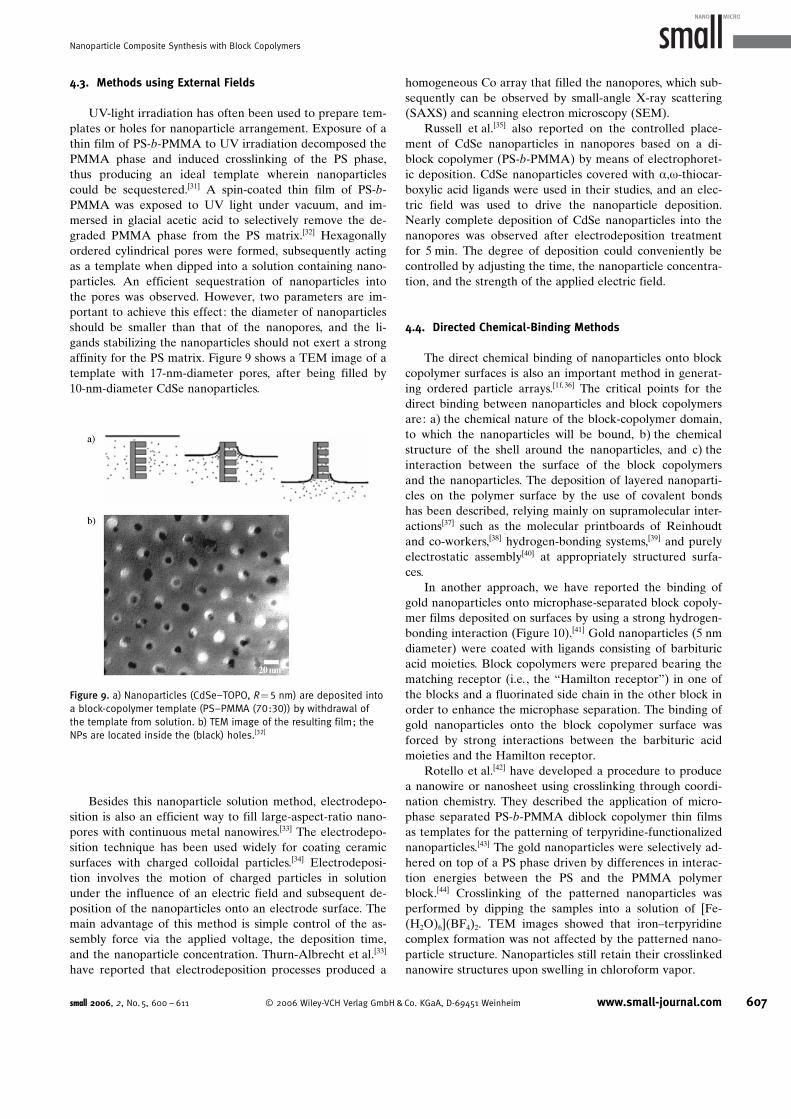
UV-light irradiation has often been used to prepare tem-plates or holes for nanoparticle arrangement. Exposure of athin film of PS-b-PMMA to UV irradiation decomposed thePMMA phase and induced crosslinking of the PS phase,thus producing an ideal template wherein nanoparticlescould be sequestered.[31] A spin-coated thin film of PS-b-PMMA was exposed to UV light under vacuum, and im-mersed in glacial acetic acid to selectively remove the de-graded PMMA phase from the PS matrix.[32] Hexagonallyordered cylindrical pores were formed, subsequently actingas a template when dipped into a solution containing nano-particles. An efficient sequestration of nanoparticles intothe pores was observed. However, two parameters are im-portant to achieve this effect: the diameter of nanoparticlesshould be smaller than that of the nanopores, and the li-gands stabilizing the nanoparticles should not exert a strongaffinity for the PS matrix. Figure 9 shows a TEM image of atemplate with 17-nm-diameter pores, after being filled by10-nm-diameter CdSe nanoparticles.
Besides this nanoparticle solution method, electrodepo-sition is also an efficient way to fill large-aspect-ratio nano-pores with continuous metal nanowires.[33] The electrodepo-sition technique has been used widely for coating ceramicsurfaces with charged colloidal particles.[34] Electrodeposi-tion involves the motion of charged particles in solutionunder the influence of an electric field and subsequent de-position of the nanoparticles onto an electrode surface. Themain advantage of this method is simple control of the as-sembly force via the applied voltage, the deposition time,and the nanoparticle concentration. Thurn-Albrecht et al.[33]
have reported that electrodeposition processes produced a
homogeneous Co array that filled the nanopores, which sub-sequently can be observed by small-angle X-ray scattering(SAXS) and scanning electron microscopy (SEM).
Russell et al.[35] also reported on the controlled place-ment of CdSe nanoparticles in nanopores based on a di-block copolymer (PS-b-PMMA) by means of electrophoret-ic deposition. CdSe nanoparticles covered with a,w-thiocar-boxylic acid ligands were used in their studies, and an elec-tric field was used to drive the nanoparticle deposition.Nearly complete deposition of CdSe nanoparticles into thenanopores was observed after electrodeposition treatmentfor 5 min. The degree of deposition could conveniently becontrolled by adjusting the time, the nanoparticle concentra-tion, and the strength of the applied electric field.
4.4. Directed Chemical-Binding Methods
The direct chemical binding of nanoparticles onto blockcopolymer surfaces is also an important method in generat-ing ordered particle arrays.[1f, 36] The critical points for thedirect binding between nanoparticles and block copolymersare: a) the chemical nature of the block-copolymer domain,to which the nanoparticles will be bound, b) the chemicalstructure of the shell around the nanoparticles, and c) theinteraction between the surface of the block copolymersand the nanoparticles. The deposition of layered nanoparti-cles on the polymer surface by the use of covalent bondshas been described, relying mainly on supramolecular inter-actions[37] such as the molecular printboards of Reinhoudtand co-workers,[38] hydrogen-bonding systems,[39] and purelyelectrostatic assembly[40] at appropriately structured surfa-ces.
In another approach, we have reported the binding ofgold nanoparticles onto microphase-separated block copoly-mer films deposited on surfaces by using a strong hydrogen-bonding interaction (Figure 10).[41] Gold nanoparticles (5 nmdiameter) were coated with ligands consisting of barbituricacid moieties. Block copolymers were prepared bearing thematching receptor (i.e., the “Hamilton receptor”) in one ofthe blocks and a fluorinated side chain in the other block inorder to enhance the microphase separation. The binding ofgold nanoparticles onto the block copolymer surface wasforced by strong interactions between the barbituric acidmoieties and the Hamilton receptor.
Rotello et al.[42] have developed a procedure to producea nanowire or nanosheet using crosslinking through coordi-nation chemistry. They described the application of micro-phase separated PS-b-PMMA diblock copolymer thin filmsas templates for the patterning of terpyridine-functionalizednanoparticles.[43] The gold nanoparticles were selectively ad-hered on top of a PS phase driven by differences in interac-tion energies between the PS and the PMMA polymerblock.[44] Crosslinking of the patterned nanoparticles wasperformed by dipping the samples into a solution of [Fe-(H2O)6](BF4)2. TEM images showed that iron–terpyridinecomplex formation was not affected by the patterned nano-particle structure. Nanoparticles still retain their crosslinkednanowire structures upon swelling in chloroform vapor.
Figure 9. a) Nanoparticles (CdSe–TOPO, R=5 nm) are deposited intoa block-copolymer template (PS–PMMA (70:30)) by withdrawal ofthe template from solution. b) TEM image of the resulting film; theNPs are located inside the (black) holes.[32]
small 2006, 2, No. 5, 600 – 611 � 2006 Wiley-VCH Verlag GmbH&Co. KGaA, D-69451 Weinheim www.small-journal.com 607
Nanoparticle Composite Synthesis with Block Copolymers

5. Applications in Technology
Nanowires with controlled diameters made from cobaltor other metals can be fabricated, which then subsequentlyact as a thermoelectric cooling device.[45] The ordered arrayof nanopores can also be used as template to transfer thecopolymer structure into the substrate.[46] Additionally,nanopores can be used as nanoreactors where catalysts canbe anchored to the base of the pores or simply act as a scaf-fold in which silicon oxide can be grown. In this case, anelectron beam can often be used to place the nanopores atspecific positions of the sample, controlling the lateral place-ment of nanostructures on a surface. Consequently, aligningthe orientation of copolymer morphologies in thin filmsoffers a very practical method for producing nanostructuresthat are amenable to technological applications.
The use of organized semiconductor nanoparticle sys-tems for photoelectrochemical applications has attractedspecific research efforts.[47] For example, core–shell nanopar-ticle systems were reported to behave as an organizedsystem that facilitated charge separation and enhanced pho-tocurrent generation when deposited on electrodes.[48]
Baron et al.[49] reported the assembly of CdS nanoparti-cles and Au/CdS nanoparticle hybrids on a gold-electrodesurface through hydrogen-bonding interactions and the ap-plication of the systems for the generation of photocurrents.The photocurrents were recorded in anhydrous THF in thepresence of triethylamine (Et3N) as the electron donor. Inthe absence of either the electron donor or the CdS nano-particles, no photocurrent was generated in the system. Theapplied potential can be tuned to control the magnitude ofthe resulting photocurrent. The photocurrent decreases asthe applied potential is negatively shifted, and is completelyblocked at �0.5 V versus a standard calomel electrode(SCE).
Upon photoexcitation of the CdS nanoparticles, an elec-tron–hole pair is generated in the nanoparticles. The trans-fer of conduction-band electrons to the electrode followedby the oxidation of the electron donor by valence-bandholes leads to the formation of the steady-state photocur-rent. Switchable photocurrents can be generated by biasingthe electrode potential at �0.5 V versus SCE, upon irradia-tion of the functionalized electrode at l=410 nm. Figure 11shows the cyclic “ON–OFF” formation of light-induced
Figure 10. a) Deposition of NPs (Au, R=2.5 nm) via directed hydrogen-bonding interactions onto a film consisting of a block copolymer.b) AFM image of the film indicating the islands of the deposited NPs. Reprinted with permission.[41]
608 www.small-journal.com � 2006 Wiley-VCH Verlag GmbH&Co. KGaA, D-69451 Weinheim small 2006, 2, No. 5, 600 – 611
reviews A. Haryono and W. H. Binder

photocurrents in the system. The efficiency of the conver-sion of light to electrical energy in this system was estimatedto be about 0.4%.
The topic of assembling luminescent CdS and CdSenanoparticles into specific domains of block copolymers hasreceived increased attention in the past, and several recentreports and publications deal with this aspect. In bulk mate-rials or surfaces, the following polymers and nanoparticleshave been used for assembly: CdS NPs (2.0–3.4 nm) up to43 wt% in hexagonally packed poly(styrene-b-ethylene ox-ide),[50a,b] CdS NPs (4.4 nm) in poly(styrene-b-acrylicacid),[50c] CdS NPs incorporated in poly(styrene-b-methylmethacrylate),[50d] wire-type CdS nanoparticles grown in cy-lindrical polymer brushes made from poly(acrylic acid-b-bu-tylacrylate),[50e] as well as CdS NPs incorporated with poly-pyrrole nanowires in porous polymer monoliths.[50f]
A different approach that does not rely on block copoly-mers but rather on spinodal demixing was reported by Mof-fitt et al. and others.[51, 1a] Two homopolymers (PS andPMMA) were admixed with CdS nanoparticles stabilizedwith a copolymer consisting of poly(acrylic acid-b-styrene)in a toluene solution. Upon spin-casting and solvent evapo-ration, lateral patterns resulted from the spinodal decompo-sition, incorporating the CdS NPs into only the PS phase onthe surface. Subsequent selective removal of the PMMApolymer lead to islands of CdS NPs on the surface. Similarapproaches have been reported by Minelli et al.[1a] withCdSe NPs (2.5 and 3.0 nm) and the use of PS/PMMA mix-tures. The electrophoretic deposition of TOPO-coveredCdSe NPs (3 nm) into the holes and trenches of PS-b-PMMA diblock copolymers via electrophoretic depositionled to excellent materials, wherein the full photolumines-cence was retained.[35] The concept to assemble CdS NPshas been investigated thoroughly by Cohen et al.[52] for usein solar-cell applications. When CdS clusters were located inthe microdomains of a norbornene block copolymer, thecollection of charge was influenced positively by the micro-phase separation.[52a] Furthermore, energy transfer from car-bazole moieties present in one block of a block copolymercould be transferred to CdS NPs present in anotherblock,[52b] which implied that the polymeric microphase canbe successfully used to tune energy-transfer processes. Simi-
lar concepts have been investigated by Schrock et al.[53] byusing CdSe/ZnS, ZnS, and CdS NPs in block copolymers de-rived from norbornenes and later via ZnSe nanostructuresin lyotropic liquid-crystal systems.[54]
Polyelectolyte nanoparticle films have been recentlyused for the construction of refractive index gradients,wherein alternating layers of poly(allylamine) hydrochlor-ide, poly(styrenesulfonate), as well as poly(acrylic acid)were used.[55] Silver nanoparticles were enriched selectivelyin the poly(acrylic acid) matrix, leading to a highly efficienttuning of the low- and higher-index regions within the film.Film thicknesses of �1.5 mm could be obtained by thismethod.
Another highly important topic concerns the selectiveincorporation of magnetic nanoparticles (mainly, iron oxideor cobalt–ferrite nanoparticles) into domains of block co-polymers. The construction of data-storage devices and theinvestigation of magnetic-exchange phenomena havebecome important in this context, thus requiring definedspatial distributions of magnetic nanoparticles. Block co-polymers consisting of poly(norbornene-b-deuterated nor-bornene dicarboxylic acid),[56a] poly(styrene-b-acrylicacid),[56b] poly(styrene-b-butylacrylate),[56c] and poly(styrene-b-ethylene/butylene-b-styrene) were used as templates to as-semble or prepare iron oxide or cobalt–ferrite nanoparti-cles.[56d] Wiesner et al.[56e] have combined a sol–gel processwith concomitant templating of poly(isoprene-b-ethyleneoxide) polymers in the presence of iron salts. After solidifi-cation and template removal at 550 8C, the formation of su-perparamagnetic, nanometer-sized g-Fe2O3 crystals was ob-served within the matrix. Potential applications include thetuning of magnetic forces and their application in molecularlabeling and catalysis. Darling et al.[56f] have described an in-teresting approach to assemble FePt nanoparticles onto athin film made from a PS-b-PMMA diblock copolymerforming hexagonally packed PMMA cylinders. The FePtnanoparticles were deposited in a solution process, generat-ing arrays of NPs in the range of 100 NPs per square micro-meter and preferentially depositing the NPs in the PSdomain. This approach holds great promise for the construc-tion of data storage modules.[56g]
Templating the distribution of iron via microphase sepa-ration of a block copolymer (poly(styrene-b-ferrocenyldi-methylsilane) was used to generate iron oxide nanoparticlesreflecting the distance of the block-copolymer template.[57]
Carbon nanotubes could be grown from these nanoparticles,which act templates and as a catalyst site for their growth.Thus, regular patterns of carbon nanotubes could be drawnby use of this method.
Another important area concerns Pd nanoparticlesinside block-copolymeric matrices. Due to their high catalyt-ic activity, a fine dispersion together with a high interfacialarea of the Pd nanoparticles is desired. Thus Horiuchiet al.[58a] have assembled Pd nanoparticles inside poly(meth-yl methacrylate-b-2-hydroxyethyl methacrylate) (PMMA-b-PHEMA) block-copolymeric micelles. Thus the Pd nanopar-ticles were produced selectively in the PHEMA block anddeposited on Si surfaces. Subsequent dry-etching led to theformation of Pd NPs�3 nm) located in lines, dots, or holes
Figure 11. Schematic representation of hydrogen-bonded CdS NPs(4–5 nm) assemblies in which electron transfer is mediated by selec-tive binding of the NPs to the electrode surface.[49]
small 2006, 2, No. 5, 600 – 611 � 2006 Wiley-VCH Verlag GmbH&Co. KGaA, D-69451 Weinheim www.small-journal.com 609
Nanoparticle Composite Synthesis with Block Copolymers

on the surface. A similar approach using a poly(styrene-b-4-vinylpyridine) block copolymer was demonstrated on surfa-ces, using the residual 4-vinylpyridine moieties as templatesfor Pd nanoparticle growth.[58b] Pd nanoparticles embeddedin poly(isoprene-2-cinnamoyloxyethyl methacrylate)shells[59a] or poly(styrene-b-4-vinylpyridine) micelles[59b] havebeen used as hydrogenation catalysts, either in water or su-percritical CO2, thus demonstrating the effectiveness offinely dispersed Pd nanoparticles for catalytic purposes.Other approaches[60] used poly(isoprene-b-2-vinyl pyridine)to effect the selective incorporation of Pd nanoparticles intospecific microdomains of the block copolymer.
6. Conclusions and Future Outlook
The microphase separation of block copolymers offers astraightforward and simple approach to organization on thenanometer scale, either as a pure scaffolding or templatingstructure (as in the case of sol–gel processes), or as a struc-ture-directing agent and functional unit. The possibility totailor the polymeric microphases and domains via synthesis,most of all by living-polymerization methods, offers wideprospects to organize functional units on the nanoscale.Nanoparticles simply open up a new dimension of chemicaland physical properties, which are often not achievable bypure (organic) polymeric structures. Most of all, the tunabil-ity of many nanoparticle properties (such as optical emis-sion, fluorescence, magnetic, and electric phenomena) bysimple size variation of the nanoparticles is advantageouswhen compared to other conventional materials. However,these advantageous properties often emerge only when ap-propriate coupling and exchange phenomena between thenanoparticles exist, thus requiring appropriate control overtheir interparticle distance, regular ordering, and location.Therefore, the use of block copolymers as templates fornanoparticle assemblies shows highly promising results.
One aspect however is still open for further research ac-tivities: The technological application of these organizednanoparticles is still in its infancy. However, this process isabout to develop, being strongly coupled to the exploitationof block-copolymer nanolithography and nanopatterningstrategies, which have emerged as efficient and powerfultechniques in recent years. From there on, the simple fabri-cation of nanoparticle assemblies will find its way into fieldssuch as molecular electronics, solar-cell applications, light-emitting diodes, and also in the medical and catalytic scien-ces.
Acknowledgements
The authors acknowledge a grant of the FWF, P14844 CHE;A.H. acknowledges the OEAD for a postdoctoral fellowship inAustria.
[1] a) C. Minelli, I. Geissbuehler, R. Eckert, H. Vogel, H. Heinzel-mann, M. Liley, Colloid Polym. Sci. 2004, 282, 1274; b) J. F. Cie-
bien, R. T. Clay, B. H. Sohn, R. E. Cohen, New J. Chem. 1998, 22,685; c) R. R. Bhat, J. Genzer, B. N. Chaney, H. W. Sugg, A. Lieb-mann-Vinson, Nanotechnology 2003, 14, 1145; d) M. R.Bockstaller, R. A. Mickiwicz, E. L. Thomas, Adv. Mater. 2005, 17,1331; e) R. Shenhar, T. B. Norsten, V. M. Rotello, Adv. Mater.2005, 17, 657; f) W. H. Binder, Angew. Chem. 2005, 117,5300; Angew. Chem. Int. Ed. 2005, 44, 5172.
[2] See, for instance: a) A. P. Alivisatos, Nat. Biotechnol. 2004, 22,47; b) N. L. Rosi, C. A. Mirkin, Chem. Rev. 2005, 105, 1547, andexamples in Chapter 5 of this Review.
[3] See, for instance: G. Bognolo, Adv. Colloid Interface Sci. 2003,106, 169.
[4] a) B. C. Bryan, M. O. Wolf, Chem. Commun. 2005, 3375; b) R.Glass, M. Mçller, J. P. Spatz, Nanotechnology 2003, 14, 1153.
[5] a) A. Noshay, J. E. McGrath, Block Copolymers, Overview andCritical Survey, Academic Press, New York, 1977, p. 56–58;b) S. Fçrster, M. Konrad, J. Mater. Chem. 2003, 13, 2671.
[6] a) M. J. Fasolka, A. M. Mayes, Annu. Rev. Mater. Res. 2001, 21,323; b) G. Kickelbick, Prog. Polym. Sci. 2003, 28, 83; c) I. W.Hamley, Nanotechnology 2003, 14, R39.
[7] J. Huh, V. V. Ginzburg, A. C. Balazs, Macromolecules 2000, 33,8085.
[8] a) R. B. Thompson, V. V. Ginzburg, M. W. Matsen, A. C. Balasz,Science 2001, 292, 2469; b) R. B. Thompson, K. O. Rasmussen,T. Lookman, Nano Lett. 2004, 4, 2455.
[9] Q. Wang, P. F. Nealey, J. J. de Pablo, J. Chem. Phys. 2003, 118,11278.
[10] J. Y. Lee, Z. Shou, A. C. Balasz, Macromolecules 2003, 36, 7730.[11] A. J. Schultz, C. K. Hall, J. Genzer, Macromolecules 2005, 38, 3007.[12] a) D. Gersappe, A. C. Balasz, Phys. Rev. E 1995, 52, 5061; b) H.
Haobin, D. Gersappe, Macromolecules 2004, 37, 5792.[13] B. Hamdoun, Eur. Polym. J. 2004, 40, 1559.[14] Y. Lin, A. Bçker, J. He, K. Sill, H. Xiang, C. Abetz, X. Li, J. Wang, T.
Emrick, S. Long, Q. Wang, A. Balasz, T. P. Russell, Nature 2005,434, 55.
[15] J. J. Chiu, B. J. Kim, E. J. Kramer, D. J. Pine, J. Am. Chem. Soc.2005, 127, 5036.
[16] K. Tsutsumi, Y. Funaki, Y. Hirokawa, T. Hashimoto, Langmuir1999, 15, 5200.
[17] M. R. Bockstaller, Y. Lapetnikov, S. Margel, E. L. Thomas, J. Am.Chem. Soc. 2003, 125, 5276.
[18] A. B. R. Mayer, Polym. Adv. Technol. 2001, 12, 96.[19] Y. Ng Cheong Chan, G. S. W. Craig, R. R. Schrock, R. E. Cohen,
Chem. Mater. 1992, 4, 885.[20] a) R. Saito, S. Okamura, K. Ishizu, Polymer 1992, 33, 1099;
b) R. Saito, S. Okamura, K. Ishizu, Polymer 1993, 34, 1183;c) R. Saito, S. Okamura, K. Ishizu, Polymer 1993, 34, 1189;d) R. Saito, K. Ishizu, Polymer 1995, 36, 4119.
[21] T. Hashimoto, M. Harada, N. Sakamoto, Macromolecules 1999,32, 6867.
[22] a) L. M. Bronstein, M. V. Seregina, O. A. Platonova, Y. A. Kaba-chii, D. M. Chernyshov, M. G. Ezernitskaya, L. V. Dubrovina, T. P.Bragina, P. M. Valetsky, Macromol. Chem. Phys. 1998, 199,1357; b) L. Bronstein, M. Seregina, P. Valetsky, U. Breiner, V.Abetz, R. Stadler, Polym. Bull. 1997, 39, 361; c) L. Bronstein, E.KrImer, B. Berton, C. Burger, S. Fçrster, M. Antonietti, Chem.Mater. 1999, 11, 1402; d) L. M. Bronstein, S. N. Sidorov, P. M.Valetsky, J. Hartmann, H. Cçlfen, M. Antonietti, Langmuir 1999,15, 6256.
[23] a) B. H. Sohn, B. H. Seo, Chem. Mater. 2001, 13, 1752; b) B. H.Sohn, B. W. Seo, S. I. Yoo, J. Mater. Chem. 2002, 12, 1730.
[24] a) J. P. Spatz, A. Roescher, S. Sheiko, G. Krausch, M. Moller,Adv. Mater. 1995, 7, 731; b) J. P. Spatz, A. Roescher, M. Moller,Adv. Mater. 1996, 8, 337; c) A. B. R. Mayer, J. E. Mark, ColloidPolym. Sci. 1997, 275, 333.
[25] H. Shen, L. Zhang, A. Eisenberg, J. Am. Chem. Soc. 1999, 121,2728.
610 www.small-journal.com � 2006 Wiley-VCH Verlag GmbH&Co. KGaA, D-69451 Weinheim small 2006, 2, No. 5, 600 – 611
reviews A. Haryono and W. H. Binder

[26] B. Hamdoun, D. Ausserre, S. Joly, Y. Gallot, V. Cabuil, C. Clinard,J. Phys. IV France 1996, 6, 493.
[27] S. W. Yeh, K. H. Wei, Y. S. Sun, U. S. Jeng, K. S. Liang, Macromo-lecules 2003, 36, 7903.
[28] a) C. C. Weng, K. H. Wei, Chem. Mater. 2003, 15, 2936; b) R. W.Zehner, W. A. Lopes, T. L. Morkved, H. Jaeger, L. R. Sita, Lang-muir 1998, 14, 241.
[29] B. H. Sohn, J. M. Choi, S. I. Yoo, S. H. Yun, W. C. Zin, J. C. Jung,M. Kanehara, T. Hirata, T. Teranishi, J. Am. Chem. Soc. 2003,125, 6368.
[30] S. W. Yeh, K. H. Wei, Y. S. Sun, U. S. Jeng, K. S. Liang, Macromo-lecules 2005, 38, 6559.
[31] a) T. Thurn-Albrecht, J. Schotter, G. A. Kastle, N. Emley, T. Shi-bauchi, L. Krusin-Elbaum, K. Guarini, C. T. Black, M. T. Tuominen,T. P. Russell, Science 2000, 290, 2126; b) T. Thurn-Albrecht, R.Steiner, J. DeRouchey, C. M. Stafford, E. Huang, M. Bal, M. Tuo-minen, C. J. Hawker, T. P. Russell, Adv. Mater. 2000, 12, 787.
[32] M. J. Misner, H. Skaff, T. Emrick, T. P. Russell, Adv. Mater. 2003,15, 221.
[33] a) T. M. Whitney, J. S. Jiang, P. C. Searson, C. L. Chien, Science1993, 261, 1316; b) P. V. Braun, P. W. Wiltzius, Nature 1999,402, 603.
[34] a) P. Sarkar, P. S. Nicholson, J. Am. Ceram. Soc. 1996, 79, 1987;b) R. C. Bailey, K. J. Stevenson, J. T. Hupp, Adv. Mater. 2000, 12,1930.
[35] Q. Zhang, T. Xu, D. Butterfield, M. J. Misner, D. Y. Ryu, T. Emrick,T. P. Russell, Nano Lett. 2005, 5, 357.
[36] C. B. Murray, C. R. Kagan, M. G. Bawendi, Ann. Rev. Mater. Sci.2000, 30, 545.
[37] a) V. L. Colvin, A. N. Goldstein, A. P. Alivisatos, J. Am. Chem. Soc.1992, 114, 5221; b) S. Westenhoff, N. A. Kotov, J. Am. Chem.Soc. 2002, 124, 2884.
[38] a) P. Maury, M. Peter, V. Mahakingam, D. N. Reinhoudt, J. Husk-ens, Adv. Funct. Mater. 2005, 15, 451; b) V. Mahaligam, S.Onclin, M. Peter, B. J. Ravoo, J. Huskens, D. N. Reinhoudt, Lang-muir 2004, 20, 11756; c) O. Crespo-Biel, B. Dordi, D. N. Rein-houdt, J. Huskens, J. Am. Chem. Soc. 2005, 127, 7594; d) T. Au-letta, B. Dordi, A. Mulder, A. Sartori, S. Onclin, C. M. Bruinik, M.Peter, C. A. Nijhuis, H. Beijleveld, H. Schçnherr, G. J. Vansco, A.Casnati, R. Ungaro, B. Ravoo, J. Huskens, D. N. Reinhoudt,Angew. Chem. 2004, 116, 373; Angew. Chem. Int. Ed. 2004,43, 369.
[39] a) A. K. Boal, B. L. Frankamp, O. Uzun, M. T. Tuominen, V. M. Ro-tello, Chem. Mater. 2004, 16, 3252; b) A. K. Boal, F. Ilhan, J. E.DeRouchey, T. Thurn-Albrecht, T. P. Russell, V. M. Rotello, Nature2000, 404, 746; c) R. Zirbs, F. Kienberger, P. Hinterdorfer, W. H.Binder, Langmuir 2005, 21, 8414; d) D. Coman, I. M. Russu, J.Am. Chem. Soc. 2003, 125, 6626; e) M. Peters, I. Rozas, I. Al-korta, J. Elguero, J. Phys. Chem. B 2003, 107, 323; f) H.-C. Lin,H.-Y. Sheu, C.-L. Chang, C. Tsai, J. Mater. Chem. 2001, 11, 2958.
[40] a) R. R. Bhat, J. Genzer, B. N. Chaney, H. W. Sugg, A. Liebmann-Vinson, Nanotechnology 2003, 14, 1145 and references citedtherein; b) N. A. Kotov, I. Dekany, J. H. Fendler, J. Phys. Chem.1995, 99, 13065; c) K. Ariga, Y. Lvov, M. Onda, I. Ichinose, T.Kunitake, Chem. Lett. 1997, 26, 125; d) Z. Tang, Y. Wang, N. A.Kotov, Langmuir 2002, 18, 7035.
[41] W. H. Binder, C. Kluger, C. J. Straif, G. Friedbacher, Macromole-cules 2005, 38, 9405.
[42] R. Shenhar, E. Jeoung, S. Srivastava, T. B. Norsten, V. M. Rotello,Adv. Mater. 2005, 17, 2206.
[43] T. B. Norsten, B. L. Frankamp, V. M. Rotello, Nano Lett. 2002, 2,1345.
[44] a) R. W. Zehner, L. R. Sita, Langmuir 1999, 15, 6139; b) R. W.Zehner, W. A. Lopes, T. L. Morkved, H. Jaeger, L. R. Sita, Lang-muir 1998, 14, 241.
[45] J. Heremans, C. M. Thrush, Phys. Rev. B 1999, 59, 12579.[46] M. Park, C. Harrison, P. M. Chaikin, R. A. Register, D. H. Adam-
son, Science 1997, 276, 1401.[47] a) C. Nasr, S. Hotchandani, W. Y. Kim, R. S. Scmehl, P. V. Kamat,
J. Phys. Chem. B 1997, 101, 7480; b) V. Pardo-Yissar, E. Katz, J.Wasserman, I. Willner, J. Am. Chem. Soc. 2003, 125, 622; c) D.Dong, D. Zheng, F.-Q. Wang, X.-Q. Yang, N. Wang, Y.-G. Li, L.-H.Guo, J. Cheng, Anal. Chem. 2004, 76, 499.
[48] E. Granot, F. Patolsky, I. Willner, J. Phys. Chem. B 2004, 108,5875.
[49] R. Baron, C.-H. Huang, D. M. Bassani, A. Onopriyenko, M.Zayats, I. Willner, Angew. Chem. 2005, 117, 4078; Angew.Chem. Int. Ed. 2005, 44, 4010, .
[50] a) S.-W. Yeh, T.-L. Wu, K.-H. Wei, Y.-S. Sun, K. S. Liang, J. Polym.Sci. Part B: Polym. Lett. 2005, 43, 1220; b) S.-W. Yeh, T.-L. Wu,K.-H. Wei, Nanotechnology 2005, 16, 683; c) C.-W. Wang, M. G.Moffitt, Langmuir 2004, 20, 11784; d) C.-W. Wang, M. G. Mof-fitt, Langmuir 2005, 21, 2465; e) M. Zhang, M. Drechsler,A. H. E. MKller, Chem. Mater. 2004, 16, 537; f) B. J. S. Johnson,J. H. Wolf, A. S. Zalusky, M. A. Hillmyer, Chem. Mater. 2004, 16,2909.
[51] C.-W. Wang, M. G. Moffitt, Chem. Mater. 2005, 17, 3871.[52] a) J. A. Gratt, R. E. Cohen, J. Appl. Polym. Sci. 2004, 91, 3362;
b) J. A. Gratt, R. E. Cohen, J. Appl. Polym. Sci. 2003, 88, 177;c) J. Gratt, R. E. Cohen, Macromolecules 1997, 30, 3137.
[53] a) D. E. Fogg, L. H. Radzilowski, B. O. Dabbousi, R. R. Schrock,E. L. Thomas, M. G. Bawendi, Macromolecules 1997, 30, 8433;b) V. Sankaran, J. Yue, R. E. Cohen, R. R. Schrock, R. J. Silbey,Chem. Mater. 1993, 5, 1133; c) C. C. Cummins, R. R. Schrock,R. E. Cohen, Chem. Mater. 1992, 4, 27.
[54] a) G. N. Karanikolos, P. Alexandridis, R. Mallory, A. Petrou, T. J.Mountziaris, Nanotechnology 2005, 16, 2372; b) R. S. Kane,R. E. Cohen, R. Silbey, Chem. Mater. 1999, 11, 90.
[55] A. J. Nolte, M. F. Rubner, R. E. Cohen, Langmuir 2004, 20, 3304.[56] a) P. Akcora, X. Zhang, B. Varughese, R. M. Briber, P. Kofinas,
Polymer 2005, 46, 5194; b) R. D. Bennett, A. C. Miller, N. T.Kohen, P. T. Hammond, D. J. Irvine, R. E. Cohen, Macromolecules2005, 38, 10728; c) V. Lauter-Pasyk, H. J. Lauter, G. P. Gordeev,P. MKller-Buschbaum, B. P. Toperveg, M. Jernenkov, W. Petry,Langmuir 2003, 19, 7783; d) G. S. Rajan, K. A. Mauritz, S. L.Strohmeyer, T. Kwee, P. Mani, J. L. Weston, D. E. Nikles, M.Shamsuzzoha, J. Polym. Sci. Part B: Polym. Lett. 2005, 43,1475; e) C. B. W. Garcia, Y. Zhang, S. Mahajan, F. DiSalvo, U.Wiesner, J. Am. Chem. Soc. 2003, 125, 13310; f) S. B. Darling,N. A. Yufa, A. L. Cisse, S. D. Bader, S. J. Sibener, Adv. Mater.2005, 17, 2446; g) S. B. Darling, S. D. Bader, J. Mater. Chem.2005, 15, 4189.
[57] C. Hinderling, Y. Keles, T. Stçckli, H. F. Knapp, T. de Los Arcos, P.Oelhafen, I. Korczagin, M. A. Hempenius, G. J. Vancso, R. Pugin,H. Heinzelmann, Adv. Mater. 2004, 16, 876.
[58] a) D. Yin, S. Horiuchi, Chem. Mater. 2005, 17, 463; b) A. W.Fahmi, M. Stamm, Langmuir 2005, 21, 1062.
[59] a) R. S. Underhill, G. Liu, Chem. Mater. 2000, 12, 3633; b) H. H.Niessen, A. Eichhorn, K. Woelk, J. Bargon, J. Mol. Catal. A 2002,182–183, 463.
[60] a) T. Hashimoto, A. Okumura, D. Tanabe, Macromolecules 2003,36, 7324; b) A. E. Ribbe, A. Okumura, K. Matsushige, T. Hashi-moto, Macromolecules 2001, 34, 8239.
Received: November 29, 2005
small 2006, 2, No. 5, 600 – 611 � 2006 Wiley-VCH Verlag GmbH&Co. KGaA, D-69451 Weinheim www.small-journal.com 611
Nanoparticle Composite Synthesis with Block Copolymers