Thesis AVAsha
158
Parametric Resonance Characteristics of Laminated Composite Twisted Cantilever Panels A thesis submitted to National Institute of Technology, Rourkela For the award of degree of Doctor of Philosophy in Engineering by A.V. Asha Under the supervision of Prof. Shishir K. Sahu Department of Civil Engineering National Institute of Technology Rourkela-769008, India April 2008
Transcript of Thesis AVAsha
Parametric Resonance Characteristics of
Laminated Composite Twisted Cantilever Panels
A thesis submitted to
National Institute of Technology, Rourkela
For the award of degree of
Doctor of Philosophy
in
Engineering by
A.V. Asha
Under the supervision of
Prof. Shishir K. Sahu
Department of Civil Engineering
National Institute of Technology
Rourkela-769008, India April 2008

ii
Dedicated
To My Parents
iii
Certificate
This is to certify that the thesis entitled “Parametric Resonance
Characteristics of Laminated Composite Twisted Cantilever
Panels”, being submitted to the National Institute of Technology, Rourkela
(India) by A.V.Asha for the award of the degree of Doctor of Philosophy
(CIVIL ENGINEERING) is a record of bonafide research work carried out by
her under my supervision and guidance. A.V.Asha has worked for more than
three years on the above problem and it has reached the standard fulfilling the
requirements of the regulations of the degree. The results embodied in this thesis
have not been submitted in part or full to any other university or institute for the
award of any degree or diploma.
Rourkela (Dr.Shishir Kumar Sahu)
Date: Professor
Department of Civil Engineering
National Institute of Technology
Rourkela-769008
Orissa, India.
iv
Acknowledgement
I express my deep sense of gratitude and indebtedness to my thesis supervisor
Dr.Shishir Kumar Sahu, Professor, Department of Civil Engineering, National
Institute of Technology, Rourkela, for his invaluable encouragement, helpful
suggestions and supervision throughout the course of this work.
I express my sincere thanks to the Director, Prof. S.K.Sarangi, National Institute
of Technology, Rourkela for motivating me in this endeavor and providing me the
necessary facilities for this study.
I would like to thank Prof. B.K.Rath, ex-head of the Civil Engineering
Department and Prof. K.C.Patra, present head of the department for their help and
cooperation during the progress of this work.
I would also like to thank Prof. R.K.Sahoo of Mechanical Engineering
Department and Prof. M.R.Barik of Civil Engineering Department for their
invaluable suggestions and help at various stages of the work.
I acknowledge with thanks the help rendered to me by all my colleagues and other
staff of the Civil Engineering Department and am grateful for their continuous
encouragement during the progress of my work.
Last but not least, I am extremely grateful to my husband and children, Arun and
Aravind, for their support and patience during this period.
(A.V.Asha)
v
ABSTRACT The twisted cantilever panels have significant applications in wide chord turbine
blades, compressor blades, fan blades and particularly in gas turbines. Structural
elements subjected to in-plane periodic forces may lead to parametric resonance,
due to certain combinations of the applied in-plane load parameters and the
natural frequency of transverse vibrations. The instability may occur below the
critical load of the structure under compressive loads over wide ranges of
excitation frequencies. Composite materials are increasingly used as load bearing
structural components in aerospace and naval structures, automobiles, pressure
vessels, turbine blades and many other engineering applications because of their
high specific strength, specific stiffness and tailorability. Thus, the parametric
resonance characteristics of laminated composite twisted cantilever panels are of
great technical importance for understanding the dynamic behaviour of structures
under in-plane periodic loads. This aspect of static and dynamic stability
behaviour of laminated composite pretwisted cantilever panels is studied in the
present investigation.
The analysis is carried out with the finite element method (FEM) using
first order shear deformation theory (FSDT), considering the effects of transverse
shear deformation and rotary inertia. An eight-node isoparametric quadratic
element is employed in the present analysis with five degrees of freedom per
node. Element elastic stiffness matrices, mass matrices and load vectors are
derived using the principle of Stationery Potential Energy. They are evaluated
using the Gauss quadrature numerical integration technique. Plane stress analysis
is carried out using the finite element method to determine the stresses and these
are used to formulate the geometric stiffness matrix. The overall stiffness and
vi
mass matrices are obtained by assembling the corresponding element matrices
using skyline technique. The eigenvalues are determined using Subspace iteration
scheme.
In this analysis the effects of various parameters such as twisting angle,
aspect ratio, thickness, curvature, number of layers, ply orientation, degree of
orthotropy, etc on the buckling and vibration behaviour of homogeneous and
laminated composite twisted cantilever panels are studied. The parametric
instability characteristics of homogeneous and laminated composite pretwisted
cantilever flat and curved panels subjected to in-plane harmonic loads are studied.
The study revealed that, due to static component of load, the instability
regions tend to shift to lower frequencies. The onset of instability occurs earlier
with increase of angle of twist of panel with wider instability regions. Unlike
twisted plates, there is significant deviation of the instability behaviour of twisted
cylindrical panels from that of untwisted cylindrical panels. Similar behaviour is
also observed for the variation of instability region of twisted spherical and
hyperbolic paraboloidal panels. The excitation frequency decreases from square to
rectangular panels with increase of aspect ratio. The ply orientation significantly
affects the onset of instability and the width of the zones of instability.
Thus the instability behaviour of twisted cantilever panels is influenced
by the geometry, material, ply lay-up and its orientation. This can be used to the
advantage of tailoring during design of composite twisted structures.
Keywords: parametric resonance, dynamic instability, pretwist, laminated
composite cantilever panels.
vii
Contents Abstract v
Contents vii
List of tables ix
List of figures xiv
Nomenclature xviii
List of Publications xxi
1. INTRODUCTION ……………………………………………………... 1 1.1: Introduction .……………………………………………………… 1
1.2: Importance of the present structural stability study …………… 1
1.3: Outline of the present work ………………………………………. 2
2. REVIEW OF LITERATURE …………………………………………. 4 2.1: Introduction ……………………………………………………….. 4
2.2: Vibration and buckling of twisted panels ……………………….. 4
2.3: Dynamic stability of twisted panels ………………………………. 19
2.4: Critical discussion …………………………………………………. 23
2.5: Objectives and scope of the present study ……………………….. 25
3. THEORY AND FORMULATION …………………………………….. 26 3.1: The Basic Problem …………………………………………………. 26
3.2: Proposed Analysis…………………………………………………... 27
3.2.1: Assumptions of the analysis ………………………………... 28
3.3: Governing Equations……………………………………………….. 29
3.3.1: Governing Differential Equations ………………………… 29
3.4: Dynamic stability studies ………………………………………….. 31
3.5: Energy Equations…………………………………………………... 32
3.5.1: Formulation of Vibration and Static Stability problems... 35
3.6: Finite Element Formulation ………………………………………. 35
3.6.1: The shell element …………………………………………… 36
3.6.2: Strain displacement relations ……………………………… 38
3.6.3: Constitutive Relations …………………………………….. 39
viii
3.6.4: Derivation of Element Matrices ………………………….. 44
3.6.5: Geometric stiffness matrix ………………………………... 45
3.7: Computer program ………………………………………………... 48
4. RESULTS AND DISCUSSIONS ………………………………………. 49
4.1: Introduction.....………………………………………………......... 49
4.2: Convergence study ………………………………………………… 50
4.3: Comparison with previous studies ……………………………….. 51
4.4: Numerical results ………………………………………………….. 55
4.5: Isotropic twisted panels …………………………………………… 55
4.5.1: Non-dimensionalization of parameters …………………… 56
4.5.2: Boundary conditions ………………………………………. 56
4.5.3: Vibration and buckling studies …………………………... 56
4.5.4: Dynamic stability studies …………………………………. 63
4.6: Cross ply twisted cantilever panels…………………………………… 66
4.6.1: Non-dimensionalization of parameters …………………… 66
4.6.2: Boundary conditions ………………………………………. 67
4.6.3: Vibration and buckling studies …………………………… 67
4.6.4: Dynamic stability studies ………………………………….. 81
4.7: Angle-ply twisted cantilever panels……………………………………. 90
4.7.1: Non-dimensionalization of parameters …………………… 91
4.7.2: Boundary conditions ……………………………………….. 91
4.7.3: Vibration and buckling studies …………………………… 91
4.7.4: Dynamic stability studies ………………………………….. 103
5. CONCLUSIONS………………………………………………………….. 112
5.1: Isotropic twisted panels ……………………………………………. 113
5.2: Cross-ply twisted cantilever panels ……………………………….. 115
5.3: Angle-ply twisted cantilever panels ………………………………. 118
5.4: Scope for further work …………………………………………….. 123
REFERENCES ……………………………………………………………… 124
APPENDIX …………………………………………………………………. 135
ix
List of Tables
No. Title Page 4.1 Convergence of non-dimensional fundamental
frequencies of free vibration of isotropic twisted
plates …………………………………………………….
50
4.2 Convergence of non-dimensional frequencies of
vibration of composite twisted cantilever plates with
45°/-45°/45° lamination ………………………………...
51
4.3 Comparison of non-dimensional frequency
parameters (λ) of the initially twisted isotropic
cantilever plate type blade ……………………………..
52
4.4 Comparison of non-dimensional fundamental
frequencies of vibration of graphite epoxy pretwisted
cantilever [θ/-θ/θ] plates ………………………………..
53
4.5 Comparison of buckling loads for a thin untwisted (Φ
= 0°) angle-ply cylindrical panel with symmetric lay-
up [0°/-α°/+ α°/-90°]s ……………………………………
54
4.6 Variation of non-dimensional frequency parameter
with angle of twist for a square isotropic cantilever
plate ……………………………………………………..
57
4.7 Variation of non-dimensional frequency parameter
with Ry/b ratio for a square isotropic cylindrical
cantilever panel …………………………………………
58
4.8 Variation of non-dimensional frequency parameter
with aspect ratio for an isotropic twisted cantilever
plate ……………………………………………………..
58
4.9 Variation of frequency in Hz with b/h ratio for a
square isotropic twisted cantilever plate ……………...
59

x
4.10 Variation of non-dimensional frequency parameter
for different twisted cantilever curved panels ………..
59
4.11 Variation of non-dimensional buckling load with
angle of twist for a square isotropic cantilever plate ...
60
4.12 Variation of non-dimensional buckling load with
angle of twist for a square isotropic cylindrical
cantilever panel …………………………………………
61
4.13 Variation of non-dimensional buckling load with Ry/b
ratio for a square isotropic twisted cylindrical
cantilever panel …………………………………………
61
4.14 Variation of non-dimensional buckling load with
aspect ratio for an isotropic twisted cantilever plate…
62
4.15 Variation of buckling load with b/h ratio for a square
isotropic twisted cantilever plate ……………………...
62
4.16 Variation of non-dimensional frequency parameter
with angle of twist for square cross-ply plates with
different ply lay-ups ……………………………………
67
4.17 Non-dimensional free vibration frequencies of square
cross-ply pretwisted cantilever plates with varying
angles of twist …………………………………………...
69
4.18 Non-dimensional free vibration frequencies of square
cross-ply pretwisted cantilever plates with varying
angles of twist (E-glass/epoxy) …………………………
70
4.19 Variation of non-dimensional frequency parameter
with R/a ratio for square cross-ply cylindrical and
spherical twisted cantilever shells ……………………..
71
4.20 Comparison of non-dimensional frequency parameter
of square cross-ply twisted plates and square cross-
ply twisted spherical shells (b/Ry = 0.25) ……………...
72
xi
4.21 Variation of non-dimensional frequency parameter
with aspect ratio for cross-ply twisted cantilever
plates with different ply lay-ups ……………………….
73
4.22 Variation of frequency in Hz with b/h ratio for square
cross-ply twisted cantilever plates with different ply
lay-ups …………………………………..........................
73
4.23 Variation of non-dimensional frequency parameter
with geometry for cross-ply twisted cantilever plates
with different ply lay-ups ………………………………
74
4.24 Variation of non-dimensional frequency parameter
with degree of orthotropy of different square cross-
ply twisted cantilever plates …………...........................
75
4.25 Variation of non-dimensional buckling load with
angle of twist for square cross-ply plates with
different ply lay-ups ……………………………………
76
4.26 Variation of non-dimensional buckling load with R/a
ratio for square cylindrical and spherical twisted
cross-ply shells ………………………………………….
77
4.27 Non-dimensional buckling load for square cross-ply
twisted plates and spherical twisted shells (b/Ry =
0.25) with different ply lay-ups ………………………..
78
4.28 Variation of non-dimensional buckling load with
aspect ratio for cross-ply twisted cantilever plates
with different ply lay-ups ………………………………
79
4.29 Variation of buckling load with b/h ratio for square
cross-ply twisted cantilever plates with different ply
lay-ups …………………………………………………..
80
4.30 Variation of non-dimensional buckling load with
geometry for square cross-ply twisted cantilever
panels with different ply lay-ups ………………………
80

xii
4.31 Variation of non-dimensional buckling load with
degree of orthotropy (E1/E2) for different square
cross-ply twisted cantilever plates …………………….
81
4.32 Variation of non-dimensional free vibration
frequencies with angle of twist and ply orientation of
angle-ply (θ/-θ/θ) pretwisted cantilever plates ………..
92
4.33 Variation of non-dimensional free vibration
frequencies with angle of twist and ply orientation of
angle-ply (θ/-θ/θ) pretwisted cantilever panels ……….
94
4.34 Variation of non-dimensional free vibration
frequencies with Ry/b ratio of square angle-ply (θ/-
θ/θ) pretwisted cantilever panels ………………………
95
4.35 Variation of non-dimensional frequency with aspect
ratio of laminated composite angle-ply (θ/-θ/θ)
pretwisted cantilever plates ……………………………
95
4.36 Variation of frequency in Hz with b/h ratio for square
laminated composite angle-ply (θ/-θ/θ) pretwisted
cantilever plates ………………………………………...
96
4.37 Variation of non-dimensional frequency with degree
of orthotropy of square angle-ply (θ/-θ/θ) pretwisted
cantilever plates ………………………………………...
97
4.38 Variation of non-dimensional buckling load with
angle of twist of square angle-ply(θ/-θ/θ) pretwisted
cantilever plates ………………………………………...
98
4.39 Variation of non-dimensional buckling load with
angle of twist of square angle-ply(θ/-θ/θ) pretwisted
cantilever plates with camber .........................................
99
4.40 Variation of non-dimensional buckling load with
angle of twist of square laminated composite angle-
ply (θ/-θ/θ) pretwisted thick cantilever plates ………..
99
xiii
4.41 Variation of non-dimensional buckling load with
aspect ratio of laminated composite angle-ply (θ/-θ/θ)
pretwisted cantilever plates …………………………...
100
4.42 Variation of non-dimensional buckling load with
angle of twist of rectangular angle-ply (θ/-θ/θ)
pretwisted cantilever plates ……………………………
101
4.43 Variation of non-dimensional buckling load with b/h
ratio of square angle-ply (θ/-θ/θ) pretwisted cantilever
plates …………………………………………………….
102
4.44 Variation of non-dimensional buckling load with
degree of orthotropy of angle-ply (θ/-θ/θ) pretwisted
cantilever plates ………………………………………...
102
xiv
List of Figures
No Title Page
3.1 Laminated composite twisted curved panel subjected
to in-plane harmonic loads …………………………….
27
3.2 Force and moment resultants of the twisted panel ….. 30
3.3 Isoparametric quadratic shell element ……………….. 36
3.4 Laminated shell element ………………………………. 40
4.1 Comparison of results of instability regions of square
untwisted angle-ply panels(45°/-45°, 45°/-45°/45°/-
45°)of present formulation with Moorthy et al. ………
54
4.2 Variation of instability region with angle of twist of
the isotropic cantilever panel, a/b = 1, Φ = 0°, 15° and
30°, α = 0.2 ………………………………………………
63
4.3 Variation of instability region with static load factor
for a square isotropic twisted cantilever panel, a/b =
1, Φ = 15°, α = 0.0, 0.2, 0.4 and α = 0.6 ………………..
64
4.4 Variation of instability region with Ry/b ratio for a
square isotropic cylindrical twisted cantilever panel,
a/b = 1, Φ = 15°, α = 0.2 ……………………………….
64
4.5 Variation of instability region with b/h ratio for a
square isotropic twisted cantilever plate, a/b = 1, Φ =
15°, α = 0.2 ……………………………………………...
65
4.6 Variation of instability region with curvature for a
square isotropic twisted cantilever panel, a/b = 1, Φ =
15°, α = 0.2, b/Ry = 0.25 ………………………………..
66
4.7 Variation of instability region with angle of twist of
the four layer cross-ply twisted plate [0°/90°/90°/0°],
a/b = 1, Φ = 0°, 15° and 30°, α = 0.2 …………………...
82
xv
4.8 Variation of instability region with number of layers
of the cross-ply twisted plate (2, 4, and 8 layers), a/b =
1, Φ = 15°, α = 0.2 ……………………………………...
83
4.9 Variation of instability region with static load factor
of a cross-ply twisted plate[0°/90°/90°/0°], a/b = 1, Φ =
15°, α = 0.0, 0.2, 0.4 and α = 0.6 ………………………..
84
4.10 Variation of instability region with static load factor
of a cross-ply twisted plate
[0°/90°/0°/90°/0°/90°/0°/90°], a/b = 1, Φ =15°, α = 0.0,
0.2, 0.4 and α = 0.6 ……………………………………...
84
4.11 Variation of instability region with aspect ratio of the
cross-ply twisted plate[0°/90°/90°/0°], Φ = 15°, α = 0.2,
a/b = 0.5, 1.0, 1.5 ………………………………………..
85
4.12 Variation of instability region with b/h ratio of the
four layer cross-ply twisted plate[0°/90°/90°/0°], a/b =
1 , Φ = 15°, α = 0.2, b/h = 200, 250 and 300 …………...
86
4.13 Variation of instability region with b/h ratio of the
cross-ply twisted plate[0°/90°/0°/90°/0°/90°/0°/90°],
a/b = 1 , Φ = 15°, α = 0.2, b/h = 200, 250 and 300 ……
86
4.14 Variation of instability region with number of layers
of the cross-ply twisted cylindrical panel, a/b = 1, Φ =
15°, α = 0.2 and b/Ry = 0.25 …………………………….
87
4.15 Variation of instability region with number of layers
of the cross-ply twisted spherical panel, a/b = 1, Φ =
15°, α = 0.2 and b/Ry = 0.25, b/Rx = 0.25 ……………....
87
4.16 Variation of instability region with number of layers
of the cross-ply twisted hyperbolic panel, a/b = 1, Φ =
15°, α = 0.2 and b/Ry = 0.25, b/Rx = −0.25 …………….
88
4.17 Variation of instability region with curvature for a
cross-ply twisted cantilever panel [0°/90°], a/b = 1, Φ
= 15°, α = 0.2, b/Ry = 0.25 ……………………………....
89
xvi
4.18 Variation of instability region with curvature for a
cross-ply twisted cantilever panel [0°/90°/90°/0°], a/b
= 1, Φ = 15°, α = 0.2, b/Ry = 0.25 ……………………...
89
4.19 Variation of instability region with degree of
orthotropy of the cross-ply twisted cantilever panel
[0°/90°/90°/0°], a/b = 1, Φ = 15°, α = 0.2 ……………...
90
4.20 Variation of instability region with angle of twist of
the angle-ply flat panel [30°/-30°/30°/-30°], a/b = 1, Φ
= 0°, 15° and 30°, α = 0.2 ……………………………….
103
4.21 Variation of instability region with number of layers
of the angle-ply twisted panel [45°/-45°/45°/-45°], a/b
= 1, b/h = 250, Φ = 15°, α = 0.2 ………………………...
104
4.22 Variation of instability region with static load factor
of an angle-ply twisted panel [30°/-30°/30°/-30°], a/b =
1, Φ = 15°, α = 0.0, 0.2, 0.4 and α = 0.6 ……………….
105
4.23 Variation of instability region with ply orientation of
an angle-ply twisted panel [θ/−θ/ θ/−θ], a/b = 1, Φ =
15°, α = 0.2, θ = 0° to 90° ………………………………
106
4.24 Variation of instability region with aspect ratio of the
angle-ply twisted panel [30°/-30°/30°/-30°], a/b = 1, 2
and 4, Φ = 15°, α = 0.2 ………………………………….
107
4.25 Variation of instability region with b/h ratio of the
angle-ply twisted panel [30°/-30°/30°/-30°], a/b = 1,
b/h =200, 250 and 300, Φ = 15°, α = 0.2 ……………….
107
4.26 Variation of instability region with angle of twist of
the angle-ply cylindrical twisted panel [30°/-30°/30°/-
30°], a/b = 1, Φ = 0°, 15° and 30°, α = 0.2, b/Ry = 0.25..
108
4.27 Variation of instability region with angle of twist of
the angle-ply spherical twisted panel [30°/-30°/30°/-
30°], a/b = 1, Φ = 0°, 15° and 30°, α = 0.2, b/Ry = 0.25,
b/Rx = 0.25 ………………………………………………
109
xvii
4.28 Variation of instability region with angle of twist of
the angle-ply hyperbolic paraboloidal twisted panel
[30°/-30°/30°/-30°], a/b = 1, Φ = 0°, 15° and 30°, α =
0.2, b/Ry = 0.25, b/Rx = −0.25 …………………………...
109
4.29 Variation of instability region with geometry for an
angle-ply twisted panel [30°/-30°/30°/-30°], a/b = 1, Φ
= 15°, α = 0.2, b/Ry = 0.25 ………………………………
110
4.30 Variation of instability region with degree of
orthotropy for an angle-ply twisted panel [30°/-
30°/30°/-30°], a/b = 1, Φ = 15°, α = 0.2, h = 2mm ……..
111
6.1 Flow chart of computer programme …………………. 137
xviii
Nomenclature The principal symbols used in this thesis are presented for easy reference. A
single symbol is used for different meanings depending on the context and
defined in the text as they occur.
English
a, b dimensions of the twisted panel
a/ b aspect ratio of the twisted panel
Aij, Bij, Dij and Sij extensional, bending-stretching coupling,
bending and transverse shear stiffnesses
b/ h width to thickness ratio of the twisted
panel
[B] Strain-displacement matrix for the element
[D] stress-strain matrix
[Dp] stress-strain matrix for plane stress
dx, dy element length in x and y-direction
dV volume of the element
E11, E22 modulii of elasticity in longitudinal and
transverse directions
G12, G13, G23 shear modulii
h thickness of the plate
J Jacobian
k shear correction factor
[Ke] global elastic stiffness matrix
[ke] element bending stiffness matrix with
shear deformation of the panel
[Kg] global geometric stiffness matrix
[Kp] plane stiffness matrix
kx, ky, kxy bending strains
[M] global consistent mass matrix
[me] element consistent mass matrix
xix
Mx, My, Mxy moment resultants of the twisted panel
n number of layers of the laminated panel
[N] shape function matrix
Ni shape functions
N (t) in-plane harmonic load
Ns static portion of load N (t)
Nt amplitude of dynamic portion of load N (t)
Ncr critical load
Nx, Ny, Nxy in-plane stress resultants of the twisted
panel
Nx0, Ny
0, Nxy0 external loading in the X and Y directions
respectively
[P] mass density parameters
q vector of degrees of freedom
Qx , Qy shearing forces
Rx, Ry, Rxy radii of curvature of shell in x and y
directions and radius of twist
T transformation matrix
u, v, w displacement components in the x, y, z
directions at any point
uo, vo, wo displacement components in the x, y, z
directions at the midsurface
U0 strain energy due to initial in-plane stresses
U1 strain energy associated with bending with
transverse shear
U2 work done by the initial in-plane stresses
and the nonlinear strain
V kinetic energy of the twisted panel
w out of plane displacement
xi, yi cartesian nodal coordinates
X, Y, Z global coordinate axis system
xx
Greek
α static load factor
β dynamic load factor
γ shear strains
xyyx ,, strains at a point
εxnl, εynl, εxynl non-linear strain components
θx, θy rotations of the midsurface normal about
the x- and y- axes respectively
λ non-dimensional buckling load
Poisson’s ratio
ξ, η local natural coordinates of the element
(ρ)k mass density of kth layer from mid-plane
mass density of the material
xyyx ,, stresses at a point
σx0, σy
0 and σxy0 in-plane stresses due to external load
τxy, τxz, τyz shear stresses in xy, xz and yz planes
respectively
frequencies of vibration
non-dimensional frequency parameter
Ω frequency of excitation of the harmonic
load
excitation frequency in radians/second
Φ angle of twist of the twisted panel
Mathematical Operators
1 Inverse of the matrix
T Transpose of the matrix
yx
, Partial derivatives with respect to x and y
xxi
List of Publications out of this Work Papers in International Journals 1. S. K. Sahu and A.V. Asha (2008): Parametric resonance characteristics of
angle- ply twisted curved panels, International Journal of Structural Stability and
Dynamics, Vol.8(1), pp.61-76
2. S. K. Sahu, A. V. Asha and R. N. Mishra (2005): Stability of Laminated
Composite Pretwisted Cantilever Panels, Journal of Reinforced Plastics and
Composites, Vol.24 (12), pp.1327-1334.
Papers Presented in Conferences
1. S. K. Sahu and A. V. Asha: Dynamic Stability of twisted laminated Composite
cross-ply panels, International Conference on Theoretical, Applied,
Computational and Experimental Mechanics (ICTACEM 2007), Dec 27-29,
2007 at IIT, Kharagpur
2. S. K .Sahu and A. V. Asha: Vibration and Stability of Cross-ply laminated
twisted cantilever plates, International conference on Vibration Problems, Feb 1-
3, 2007 at B.E College, Shibpur, Kolkata.
3. S. K.Sahu and A. V. Asha: Dynamic Stability of Laminated Composite twisted
curved Panels, IXth International conference on “Recent advances in Structural
Dynamics”, July 2006, Institute of Sound and Vibration Research, University of
Southampton, UK.
1
CHAPTER 1
INTRODUCTION
1.1: Introduction
The twisted cantilever panels have significant applications in wide chord turbine
blades, compressor blades, fan blades, aircraft or marine propellers, helicopter
blades, and particularly in gas turbines. This range of practical applications
demands a proper understanding of their vibration, static and dynamic stability
characteristics. The damage caused by blades failing due to vibratory fatigue can
be catastrophic at worst and at the very least result in additional engine
development costs due to redesign and repair. Due to its significance, a large
number of references deal with the free vibration of twisted plates.
1.2: Importance of the present structural stability study
The blades are often subjected to axial periodic forces due to axial components of
aerodynamic or hydrodynamic forces acting on the blades. Structural elements
subjected to in-plane periodic forces may lead to parametric resonance, due to
certain combinations of the values of load parameters. The instability may occur
below the critical load of the structure under compressive loads over wide ranges
of excitation frequencies. Composite materials are being increasingly used in
turbo-machinery blades because of their specific strength, stiffness and these can
be tailored through the variation of fiber orientation and stacking sequence to
obtain an efficient design. Thus the parametric resonance characteristics of
laminated composite twisted cantilever panels are of great importance for
2
understanding the systems under periodic loads. The distinction between good
and bad vibration regimes of a structure, subjected to in-plane periodic loading
can be distinguished through an analysis of dynamic instability region (DIR)
spectra. The calculation of these spectra is often provided in terms of natural
frequencies and the static buckling loads. So, the calculation of these parameters
with high precision is an integral part of dynamic stability analysis of twisted
plates.
A comprehensive analysis of the vibration problems of homogeneous
turbomachinery blades, modeled as beams has been studied exhaustively. Some
studies are available on dynamic stability of untwisted plates and shells. The
vibration aspects of laminated composite pretwisted blades, which have
increasing application in recent years, are scanty in literature. The static and
dynamic stability studies on twisted structures are the subject of renewed interest
by various researchers. It is clear from the above discussion, that the process of
investigating the different aspects of vibration and stability studies on twisted
panels is a current problem of interest. A thorough review of earlier works done in
this area becomes essential to arrive at the objective and scope of the present
investigation. The detailed review of literature along with critical discussions is
presented in the next chapter.
1.3: Outline of the present work
The present study mainly deals with the parametric resonance characteristics of
homogeneous and laminated composite twisted cantilever panels. The influence
of various parameters like angle of twist, curvature, side to thickness ratios,
number of layers, lamination sequence, and ply orientation, degree of orthotropy,
static and dynamic load factors on the vibration and instability behaviour of
twisted panels are examined.
The governing equations for the dynamic stability of laminated
composite doubly curved twisted panels/shells subjected to in-plane harmonic
3
loading are developed. The equation of motion represents a system of second
order differential equations with periodic coefficients of the Mathieu-Hill type.
The development of the regions of instability arises from Floquet’s theory and the
solution is obtained using Bolotin’s approach using finite element method. The
governing differential equations have been developed using the first order shear
deformation theory (FSDT).
This thesis contains five chapters. In this chapter, a brief introduction of
the importance of this study has been outlined.
In chapter 2, a detailed review of the literature pertinent to the previous
works done in this field has been listed. A critical discussion of the earlier
investigations is done. The aim and scope of the present study is also outlined in
this chapter.
In chapter 3, a description of the theory and formulation of the problem
and the finite element procedure used to analyse the vibration, buckling and
parametric instability characteristics of homogeneous and laminated composite
twisted cantilever panels is explained in detail. The computer program used to
implement the formulation is briefly described.
In chapter 4, the results and discussions obtained in the study have been
presented in detail. The effects of various parameters like twist angle, lamination
sequence, ply orientation, degree of orthotropy, aspect ratio, width to thickness
ratio and in-plane load parameters on the vibration, buckling and dynamic
instability regions is investigated. The studies have been done for homogeneous,
cross-ply and angle-ply laminated composite twisted cantilever panels separately.
Finally, in chapter 5, the conclusions drawn from the above studies are
described. There is also a brief note on the scope for further study in this field.
4
CHAPTER 2
REVIEW OF LITERATURE
2.1: Introduction
The vast use of turbomachinery blades lead to significant amount of research over
the years. Due to its wide range of application in the practical field, it is important
to understand the nature of deformation, vibration and stability behaviour of
cantilever twisted plates. Though the present investigation is mainly focused on
stability studies of twisted panels, some relevant researches on vibration, static
stability and dynamic stability of untwisted plates are also studied for
completeness. The literature reviewed in this chapter are grouped into
Vibration and buckling of twisted panels
Dynamic stability of twisted panels
for homogeneous and laminated composite applications.
2.2: Vibration and buckling of twisted panels
With the continually increasing use of turbomachinery at higher performance
levels, especially in aircraft, the study of vibration problems arising in twisted
blades has become increasingly important. Free vibration frequencies and mode
shapes are essential for the analysis of resonant response and flutter. Due to its
5
significance in structural mechanics, many researchers have worked on the
vibration characteristics of turbomachinery blades.
An excellent survey of the earlier works in the free vibration of
turbomachinery blades was carried out by Rao [1973, 1977a, and 1980], Leissa
[1980, 1981] and Rosen [1991] through 1991 for both stationary and rotating
conditions. The vast majority of earlier researchers studied the vibration
characteristics of turbine blades using assumptions of simple beam theory. The
most thorough work to develop a comprehensive set of equations representing the
vibrating blade as a beam was presented in a sequence of papers by Carnegie
[1957, 1959, 1972] and his co-workers. Carnegie [1957] derived the potential
energy functions for a twisted blade of arbitrary cross-section and variational
methods were then employed to obtain static equations of equilibrium describing
bending about two axes and torsion. Numerical results were obtained for blades of
rectangular and aerofoil cross-section. Carnegie [1959a] developed a set of
equations defining the dynamic motion of a pretwisted aerofoil blade and
investigated the effect of pretwist on the frequencies of vibration using the
Rayleigh-Ritz method. The dynamic effects due to blade rotation while mounted
on a disk were addressed by Carnegie [1959b]. This work studied the effects of
both the stabilizing (frequency increasing) primary and destabilizing (frequency
decreasing) secondary centrifugal force effects. The additional torsional stiffening
of twisted blades was expounded upon further by Carnegie [1962] and the effects
of shear deformation and rotary inertia were also discussed [1964]. The most
general potential and kinetic energy functions, along with corresponding
equations of motion were summarized by Carnegie [1966]. Dawson [1968] used
the Rayleigh–Ritz method and transformation techniques to study the effects of
uniform pretwist on the frequencies of cantilever blades. Carnegie and Dawson
[1969a] studied the modal curves of pretwisted beams of rectangular cross-section
and the vibration characteristics of straight and pretwisted asymmetrical aerofoil
blades [1969b, 1971]. This was done by transforming the equations of motion to a
set of simultaneous first-order differential equations and by integration using
6
Runge-Kutta method. Carnegie and Thomas [1972] and Rao [1972, 1977b] used
the Rayleigh–Ritz method and Ritz–Galerkin method to study the effects of
uniform pretwist and the taper ratio respectively on the frequencies of cantilever
blades. Ansari [1975] analysed the evaluation of the nonlinear modes of vibration
of a pretwisted non-uniform cantilever blade of unsymmetrical cross section
mounted on the periphery of a rotating disk. The effect of shear deformation,
rotary inertia and coriolis forces were included. Gupta and Rao [1978b] calculated
the frequencies of a cantilever beam of varying width and depth at varying angles
of twist. The effects of shear deformation and rotary inertia were considered in
deriving the elemental matrices. Subrahmanyam and Rao [1982] used the
Reissner method to determine the natural frequencies of uniformly pretwisted
tapered cantilever blading. Chen and Jeng [1993] utilized the finite element
method to analyze the vibration behaviour of a pretwisted blade with a single
edge crack. The influence of crack locations and crack size on dynamic
characteristics of twisted blades was studied. The dynamic response of twisted,
non-uniform rotating blades was investigated by Hernried and Bian [1993]
neglecting torsional, axial and warping deformations. Choi and Chu [2001]
proposed the modified differential quadrature method to study the vibration of
elastically supported turbomachinery blades. A pretwisted blade with varying
cross-section was modelled as a Timoshenko beam. The equations of motion and
the boundary conditions for the coupled flexural and torsional vibration of the
blade were obtained by using Hamilton's principle. Equations of motion for the
vibration analysis of rotating pretwisted blades were derived by a modelling
method which employed hybrid deformation variables by Yoo, Park and Park
[2001]. The derived equations were transformed into dimensionless forms in
which dimensionless parameters were identified. The effects of the dimensionless
parameters on the modal characteristics of rotating pretwisted blades were
investigated. In particular, eigenvalue loci veering phenomena and associated
mode shape variations were observed and discussed in this work. Yoo, Kwak and
Chung [2001] investigated the vibration of a pretwisted blade with a concentrated
7
mass, using beam model. The equations of motion were derived based on a
modelling method that employed hybrid deformation variables. The effects of the
dimensionless parameters on the modal characteristics of the rotating blade were
investigated through numerical analysis.
While these works were complete in their own right, their techniques
treated the blades as beams i.e. as a one-dimensional case. A beam model
represents a turbine engine blade reasonably well if the blade has high aspect ratio
or the blade is reasonably thick and only the first few vibration frequencies and
mode shapes are needed accurately. Many blades in sections of turbomachinery
have a small aspect ratio and are thin blades. The beam idealization is highly
inaccurate for the blade with moderate to low aspect ratio. Dynamic response
studies require results for many modes of vibration. This earlier idealization could
also not adequately handle the newer light weight, low aspect ratio turbine
blading where the blades are more likely to behave as plates or shells rather than
beams.
The emergence of digital computers with their enormous computing
speed and core memory capacity changed the outlook of structural analysts and
led to the application of the finite element method to blade vibration problems.
This approach is widely used in all areas of modern structural analysis, and is
particularly well suited to cope with blades of general configuration, including
arbitrary curvatures and twist, variable thickness and irregular shapes. All types of
finite element formulation can be found in the literature of turbomachinery blade
vibration analysis, including elements which are triangular, quadrilateral, flat
plate or shell, conforming or nonconforming. Dokainish and Rawtani [1969]
studied the vibration characteristics of pretwisted cantilever plates using a flat
triangular element. The twisted plate model shows not only the chord wise
bending modes found in plates but also the increasing frequency of torsional
modes with increasing angle of twist.
8
A twisted plate may be considered as a shell in which the curvature of
the mid-surface in two orthogonal directions is zero, but there is an angle of twist.
Many of the earlier works also included the rotational aspects of blades in the
vibration analysis. These effects were studied by Dokainish and Rawtani [1971]
who investigated the effects of rotation on untwisted plates. They analyzed the
effect of various plate geometries and velocity on the frequencies of untwisted
plates. All three components of centrifugal body force which arise were utilized.
The work showed the significant destabilization that could arise from the z-
component of the force. The plate was modeled by a mesh of triangular finite
elements. Convergence studies for various mesh sizes were made and numerical
results for the frequencies and mode shapes were presented for the first five
modes. Rawtani and Dokainish [1972] extended their rotating plate analysis to
twisted rotating plates using the same flat triangular elements. The effects of static
deformation due to angular rotation on the vibration frequencies were considered.
Numerical results were given for aspect ratios from 1 to 3 and twist angles up to
90°. Similar results for rotating flat plates were obtained by Bossak and
Zienkiewicz [1973] using 3D finite elements to study the vibration analysis of
rotating untwisted plates. Henry and Lalanne [1974] investigated the effects of
rotation using a finite element method with plate triangular elements. Results for
the first five modes of an existing compressor blade at 0 and 10000 RPM were
presented. MacBain [1975] conducted a combined numerical and experimental
study of the effects of varying tip twist and increasing centrifugal loading on the
resonant characteristics of cantilever plates. The patterns which were very clear
were presented for the first ten modes of a particular blade. Numerical results for
both rotating and non rotating blades were obtained using the NASTRAN finite
element program and were compared to those obtained experimentally using
holographic interferometer. Abbas [1979] used the finite element method to
determine the natural frequencies of uniformly pretwisted tapered cantilever
blading. Thomas and Sabuncu [1979] presented a finite element model for the
dynamic analysis of an asymmetric cross-section blade. The stresses and

9
deformations of pretwisted and tapered rotating blades were examined using finite
element method by Ramamurti and Sreenivasamurthy [1980]. Three-dimensional,
twenty-node isoparametric elements were used for the analysis. Sreenivasamurthy
and Ramamurthy [1980] studied the effect of tip mass on the frequencies of
vibration of a rotating pretwisted cantilever plate. In addition, Ramamurti and
Kielb [1984] predicted eigen frequencies of twisted rotating plates. Karada [1984]
investigated the dynamic characteristics of rotating and non-rotating practical
bladed disks by taking blade shear center effects into account using both thin and
thick beam and plate theories and the finite element method in the analysis.
Leissa et al. [1984] observed that there was a wide disagreement among
the twisted plate natural frequencies obtained by different analytical methods.
Previously published literature showed widely different results for the free
vibration frequencies of twisted cantilever plates. In the above study, numerical
results were obtained for a set of twenty different twisted plates having various
aspect ratios, thickness ratios and pretwist angles. Although some of the best-
known computational procedures (especially finite element codes) were used by
analysts with great experience, the numerical results obtained showed
considerable disagreement. The disagreement among the frequencies obtained by
analytical methods led to experimental and analytical investigations by Kielb et
al. [1985a, 1985b, 1985c].The experimental portion of a joint government/
industry/ university research study on the vibrational characteristics of twisted
cantilevered plates was presented by Kielb et al. [1985a]. The overall purpose of
the study was to assess the capabilities and limitations of existing analytical
methods in predicting the vibratory characteristics of twisted plates. The resulting
non-dimensional frequencies and mode shapes were presented as a function of
plate tip twist. The trends of the natural frequencies as a function of the governing
geometric parameters were discussed. Leissa et al. [1986] also studied the twisted
plate problem using a three dimensional model. The three dimensional solution
yielded slightly higher frequencies than the experimental ones. This may have
been due to the difficulty of satisfying the clamped edge conditions
10
experimentally. A three dimensional analytical model to compute the deflection,
stress, and eigenvalues in rotor blades was proposed by El Chazly [1993] using a
bending triangular plate finite element. Both membrane and bending stiffness
were considered in deriving the element stiffness matrix. Lift and drag forces
created in steady wind conditions were analyzed as normal and tangential forces
on the blade sections at certain angles of attack. The results showed that the
maximum stresses occurred at the root of the blades for all configurations in the
spanwise direction and that the tapered blade, in addition to saving material
weight, diminished the stresses obtained. It was found that the twisting of the
blade led to the increase of the stiffness and the decrease of the stresses. However
the three dimensional solution, in comparison, was considered lengthy.
Turbine engine blades are also made with cambered cross-sections, i.e.,
they could have a radius of curvature in one or both directions. A small amount of
camber considerably increases the longitudinal stiffness of a blade and,
correspondingly the frequencies of vibration modes that are primarily longitudinal
bending. A plate model of a blade is of limited value in such cases because the
plate is flat and has no curvature. Plate models are useful in identifying the
existence of modes that cannot be found by beam analysis, particularly those
involving chord wise bending and as a limiting case check for the results of shell
analyses. In general, the geometry of the mid surface of the blade is considered
more complicated than a plate element. The mid surface may have two
components of curvature and one of twist. These components require three
coefficients of curvature Rx, Ry and Rxy. Also Rx, Ry and Rxy may not be constants
but may vary along the blade. These considerations prompted the use of shell
theory in the study of vibration characteristics of twisted blades. Leissa [1980]
reviewed the earlier works on vibration of turbomachinery blades using shell
analysis. Petericone and Sisto [1971] used the Rayleigh-Ritz method based on
thin shell theory to investigate the influence of pretwist and skew angle on
nonrotating blades. They examined two types of twisted plates corresponding to
rectangular and skewed plates pretwisted at a constant rate. Membrane strains and

11
curvature changes were based upon the helicoidal shell theory and their numerical
results were obtained by Ritz method using orthogonal polynomials as admissible
functions. Numerical results were obtained for twist angles up to 45°. Several
other methods were also used for the analysis of turbo machinery blades. Toda
[1971] investigated nonrotating pretwisted plates using the Galerkin method,
beam functions and shallow shell theory to analyze rectangular forms. He
compared his results with those from experiments. Beres [1974] also investigated
nonrotating blades using Hamilton’s equations, Novozhilov strain-displacement
shell equations and power series trial functions. Nodal patterns and frequencies of
the first five modes were given for several configurations of straight and skewed
helicoidal shells. Gupta and Rao [1978a] used Hamilton’s principle and shallow
shell equations to analyze the torsional vibration of nonrotating twisted plates
considering aspect ratio varying from 1 to 8 with pretwist angles form 0° to 90°.
Leissa, Lee and Wang [1981] studied the vibrations of untwisted cantilevered
shallow cylindrical shells of rectangular planform using shallow shell theory and
Ritz formulation with algebraic polynomial trial functions for the displacements.
The work presented accurate non-dimensional frequency parameters for wide
ranges of aspect ratio, shallowness ratio and thickness ratio. Leissa, Lee and
Wang [1982] employed the same approach to determine the frequencies of turbo-
machinery blades (isotropic twisted plates) with twist for different degrees of
shallowness and thickness. This study concluded that the shallow shell theory can
be used for twisted plates with an angle of twist of not more than 45°. Leissa, Lee
and Wang [1983] studied the vibrational characteristics of doubly curved shallow
shells having rectangular planforms, clamped along one edge and free on the
other three. The solution procedure used the Ritz method with algebraic
polynomial trial functions. Convergence studies were made, and accurate
frequencies and contour plots of mode shapes were presented for various
curvature ratios, including spherical, circular cylindrical and hyperbolic
paraboloidal shells. Leissa and Ewing [1983] investigated the free vibration of
turbomachinery blades by the beam and shell theories which included cambered
12
and/or twisted blades of uniform thickness. The Ritz method was used to provide
the results for the shell analysis and was compared to the published results by the
beam theory with and without torsional warping constant. Tsuiji et al. [1987]
derived the fundamental equations needed to investigate the free vibrations of thin
pretwisted plates. The strain-displacement relationships were derived by
employing assumptions of the thin shell theory, and their simplified forms were
proposed for plates having relatively large length-to-width ratios. The principle of
virtual work for the free vibration of the thin pretwisted plates was formulated.
The equation derived was used to analyze the free vibrations of thin pretwisted
plates by the Rayleigh-Ritz procedure. Rao and Gupta [1987] investigated the free
vibration characteristics of rotating pretwisted small aspect ratio blades using
classical bending theory of thin shells. Variation of natural frequencies with
various parameters like pretwist, speed of rotation, stagger angle and disc radius
were presented in this study. Theoretical natural frequencies and mode shapes of
the first four coupled modes of a uniform pretwisted cantilever blade and the first
five coupled flexural frequencies of pretwisted tapered blades were determined.
Walker [1978] studied the free vibration of cambered helicoidal fan
blades. A conforming finite shell element suitable for the analysis of curved
twisted fan blades was developed and applied to a number of fan blade models.
The element was assumed to be a doubly curved right helicoidal shell, in which
the curvature is shallow with respect to the twisted base plane defining the
helicoid. Element stiffness and mass formulations were based on Mindlin's theory
and included the effects of transverse shear and rotary inertia. The thin shell
element was used to predict the natural frequencies and mode shapes of a number
of fabricated fan blade structures and the results were correlated with experiment.
It was found that the finite element predictions converged very rapidly in a
monotonic fashion towards the experimental results, even for coarse finite
element meshes. Sreenivasamurthy and Ramamurti [1981] used the finite element
technique to determine the natural frequencies of a pretwisted and tapered plate
mounted on the periphery of a rotating disc. The pretwisted plate was idealized as

13
an assemblage of three noded triangular shell elements with six degrees of
freedom at each node. In the analysis the initial stress effect (geometric stiffness)
and other rotational effects except the Coriolis acceleration effect were included.
The eigenvalues were extracted by using a simultaneous iteration technique.
Computation of frequencies was carried out for plates of aspect ratios 1 and 2.
Other parameters considered were pretwist, taper, skew angle and disc radius.
From the results of computations an extension to the existing empirical formulae
derived by Dokainish and Rawtani [1971] was suggested for computing natural
frequencies of rotating pretwisted and tapered cantilever plates. Naim and Ghazi
[1990] developed a ten-node triangular shell element for vibration analysis and
applied it to study the free vibration of rectangular untwisted as well as twisted
plates and shells of different boundary conditions.
In almost all the literature on the vibrations of turbomachinery blades in
the earlier years, the material of the blade was taken to be isotropic. Efforts to
improve the operating capabilities of turbine engine blades with composite
materials were also being made. To tailor the structural properties, fibre
reinforced composite laminates are increasingly used for designing
turbomachinery blades requiring higher strength, more durability and less weight.
There are unlimited ways of tailoring the mechanical properties of laminated
composites to suit design requirements. Classical methods of analysis were being
used to study the free vibration of composite twisted cantilever blades by many
early researchers since these methods were well suited for parameter studies
showing the effects of changing aspect ratio, thickness, shallowness, pretwist,
disk radius and angular velocity upon the frequencies and mode shapes. These
methods were particularly useful in obtaining a physical understanding of the
problem and in preliminary design. In addition, many researchers also analysed
composite plates using finite element methods. Chamis and his coworkers [1974,
1975] studied the free vibration characteristics of composite fan blades using the
finite element method. Chamis [1977] also carried out a free vibration analysis
complete with natural frequencies and mode shapes of composite fan blades
14
(graphite fibre reinforced polymide matrix- HTS/K601) for high speed
applications. He tested HTS/K601 laminated composite blades using holographic
technique and compared the test data with the theoretical results obtained using
the finite element package NASTRAN. This was the first known study of the
effects of twist angle upon the frequencies and mode shapes of laminated
composite twisted cantilever plates. Theoretical results showed that different
laminate configurations from the same composite system had only small effects
on the blade frequency. White and Bendiksen [1987] studied the aeroelastic
behaviour of titanium and composite flat blades of low aspect ratio using a
Rayleigh-Ritz formulation. The blade mode included plate type mode to account
for chordwise bending. Bhumbla et al. [1990] studied the natural frequencies and
mode shapes of spinning laminated composite plates using finite element method.
A first order shear deformation plate theory was used to predict the free vibration
frequencies and mode shapes in spinning laminated composite plates. The natural
frequencies and mode shapes of isotropic and laminated composite plates as
functions of angular velocity, pitch angle, and sweep angle were presented. A
complete and mathematically consistent set of equations for laminated composite
shallow shells including equations of motion, boundary conditions and energy
functionals was presented by Leissa and Qatu [1991]. It was shown that the
energy functionals derived were consistent with the equations of motion and
boundary conditions, and therefore could be used with energy approaches such as
the Ritz method. These equations were successfully applied to the vibrations of
laminated composite twisted cantilevered plates and shallow shells by Qatu and
Leissa [1991]. The Ritz method with algebraic polynomial displacement functions
was used. The effect of the angle of twist, thickness ratio and fiber orientation
angle upon the natural frequencies and mode shapes of three-layer, E-glass/epoxy
and graphite/epoxy angle-ply plates were studied. The experimental behaviour of
spinning, pretwisted laminated composite plates was investigated by Lapid et al.
[1993]. The purpose of these experiments was to establish an experimental
database consisting of strains, deflections, and natural frequencies as a function of
15
rotational velocity. Six different plate sets were tested which included three
different stacking sequences (two symmetric, one asymmetric), two different
initial twist levels (0 deg, 30 deg), and two different initial twist axis locations
(midchord, quarter-chord). The plates were spin tested at four different
combinations of pitch and sweep. It was observed that the location of the pretwist
axis and the level of pretwist greatly affected the strains and deflections of the
spinning plate, while the pretwist level affected only the measured natural
frequencies. The vibration and damping behaviour of cantilevered pretwisted
composite blades of glass fiber reinforced plastics was studied by Nabi and
Ganesan [1993] using a three noded triangular cylindrical shell element. The
effects of pretwist, fiber orientation, skew angle, taper and aspect ratio on natural
frequency and damping were investigated. Lim and Liew [1993] investigated the
vibratory characteristics of pretwisted composite symmetric laminates with
trapezoidal planform. A governing eigenvalue equation was derived based on the
Ritz minimization procedure. This formulation showed that the bending and
stretching effects of these symmetric laminates were coupled by the presence of
twisting curvature. This method was applied to determine the vibration response
of the problem. The effects of angles of twist and lamination parameters upon the
vibration frequencies were examined. Vibration characteristics of pretwisted
metal matrix composite blades were analyzed by using beam and plate theories by
Nabi and Ganesan [1996]. A beam element with eight degrees of freedom per
node was developed with torsion -flexure, flexure -flexure and shear -flexure
couplings which are encountered in twisted composite beams. A triangular plate
element was used for the composite material to model the beam as a plate
structure. Both theories were validated for the isotropic case. This work
summarized the quantitative comparison of natural frequencies of composite
blades obtained by these theories. A parametric study was carried out for the
beam and plate elements, the parameters being twist angle, fiber orientation, taper
ratio and lamination scheme. A study of combined effect of initial twist and
composite induced elastic couplings was presented by Rand and Barkai [1997] in
16
addition to nonlinear experimental data. Karmakar and Sinha [1997] analyzed the
free vibration of laminated composite pretwisted cantilever plates using finite
element method. A nine-node three-dimensional degenerated composite shell
element was used for the analysis. Plates with exponentially varying thickness and
variable chordwise width were studied. Effects of angle of pretwist, thickness
ratio, fiber orientation, aspect ratio, skew angle and precone angle on the natural
frequencies of graphite/epoxy plates were investigated. Parhi, Bhattacharya and
Sinha [1999] studied the dynamic analysis of multiple delaminated composite
twisted plates using the finite element method. Using the principle of virtual work
and the Rayleigh–Ritz method with two dimensional algebraic polynomial
displacement functions, the governing equation of vibration for a laminated
composite cylindrical thin panel with twist and curvature was presented by Hu
and Tsuiji [1999]. The effects of angle of twist, curvature, characteristics of
material, the number of layers, stacking sequence and fiber orientation on
vibration frequency parameters of laminated cylindrical thin panels with twist and
curvature were studied, and some vibration mode shapes were also plotted to
explain the variations of the vibration caused by them. He, Lim and Kitipornchai
[2000] presented the free vibration of symmetric as well as anti-symmetric
laminates explaining the limit of linear twisting curvature. They used a
computational method for characterizing the resonant frequency properties of
cantilever pretwisted plates composed of fibre-reinforced laminated composites. It
aimed to simulate a laminated turbomachinery blade or a fan blade with a
relatively small aspect ratio for which the conventional beam model failed to
provide accurate solutions. Numerical solutions were presented and the effects of
angle of pretwist, aspect ratio, and symmetric and antisymmetric lamination for
two different composite laminates were analyzed. Kuang and Hsu [2002]
investigated the effects of the fiber orientation, damping, inclined angle and
rotation speed on the natural frequencies of tapered pretwisted composite blades,
employing the differential quadrature method (DQM). Hu et al. [2002]
investigated the vibration of twisted laminated composite conical shells by the
17
energy method. A methodology for free vibration of a laminated composite
conical shell with twist was proposed, in which the strain–displacement
relationship of a twisted conical shell was given by considering the Green strain
tensor on the general thin shell theory. The principle of virtual work was utilized
and the governing equation was formulated by the Rayleigh–Ritz procedure with
algebraic polynomials in two elements as admissible displacement functions. Lee
et al. [2002] studied the vibration of twisted cantilevered conical composite
shells, using finite element method based on the Hellinger-Reissner principle.
This study presented the twisting angle effect on vibration characteristics of
conical laminated shells. For shells with a large curvature, the fundamental
frequency, which was always characterized by the bending mode, was almost
constant and independent of twisting angle. It was found that the twisting angle
greatly affected the twisting frequency and mode shape. Considering transverse
strain and rotary inertia, Hu et al. [2004] studied the vibration of angle-ply
laminated plates with twist using a Rayleigh-Ritz procedure. An accurate strain–
displacement relationship of a twisted plate was derived using the Green strain
tensor on the general shell theory and the Mindlin plate theory. The equilibrium
equation for free vibration was given by the principle of virtual work and was
solved by using the Rayleigh–Ritz procedure with normalized characteristic
orthogonal polynomials generated by the Gram–Schmidt process. The parametric
effects of fibre angle, twist angle, thickness ratio and stacking sequence on the
vibration frequencies and mode shapes of laminated plates were studied.
Although extensive free vibration frequencies and mode shapes were studied, the
results were however confined to symmetric laminates only.
McGee and Chu [1994] presented the three dimensional continuum
vibration analysis for rotating, laminated composite blades. The Ritz method was
used to minimize the dynamic energies with the displacements approximated by
mathematically complete polynomials satisfying the vanishing displacement
conditions at the blade root section. Non-dimensional frequency parameters are
presented for various rotating, truncated quadrangular pyramids which served as
18
first approximations of practical blades. The influence of a number of blade
parameters on the frequency parameters was studied. Chandiramani et al. [2003]
studied the free and forced vibration of rotating pretwisted composite blades,
including transverse shear flexibility, centrifugal and coriolis effects. Kee and
Kim [2004] analyzed the vibration characteristics of initially twisted rotating shell
type composite blades. The blade was assumed to be a moderately thick open
cylindrical shell, and was oriented arbitrarily with respect to the axis of rotation to
consider the effects of disc radius and setting angle. A general formulation was
derived for the initially twisted rotating shell structure including the effect of
centrifugal force and Coriolis acceleration and the transverse shear deformation
and rotary inertia. The effects of various parameters like initial twisting angles,
thickness to radius ratios, layer lamination and fiber orientation of composite
blades were investigated.
Since Coulomb's and Saint-Venant's fundamental work, many
researchers have studied the effect of twisting on elastic bodies. The study on
stability characteristics of twisted plates is however relatively new. Crispino and
Benson [1986] studied the stability of thin, rectangular, orthotropic plates which
were in a state of tension and twist. A transfer matrix method was used to obtain
numerical solutions to the linearized von Kármán plate equations, and to
determine critical angles of twist per unit length which buckle the plate. Results
were presented, in a compact non-dimensional form, for a range of material,
geometric and loading parameters. It was found that orthotropism significantly
affected the stability of the plate. The effect of thermal gradient and tangency
coefficient on the stability of a pretwisted, tapered, rotating cantilever with a tip
mass and subjected to a concentrated partial follower force at the free end was
investigated by Kar and Neogy [1989]. The non-self adjoint boundary value
problem was formulated with the aid of a conservation law using Euler-Bernoulli
theory. The associated adjoint boundary value problem was introduced and an
apposite variational principle was derived. Approximate values of critical load
19
were calculated on the basis of this variational principle and the influence of
different parameters on the stability of the system was studied.
Piezoelectric materials are becoming increasingly popular in the
emerging field of adaptive structures. In particular, active control of wings and
helicopter rotors using these materials is being pursued currently. Thirupathi et al.
[1997] made an effort at modeling piezoelectric actuated blades for
turbomachinery applications. A laminated general quadrilateral shell finite
element with eight nodes and curved edges was developed for this purpose. The
mathematical formulation of the element was described. Experiments were
conducted on a commercially available piezoceramic bimorph. The finite-element
and experimental results were shown to match very well. The laminated element
developed was then used to perform a static analysis of typical turbomachinery
blades. Effects of the angle of pretwisting and aspect ratio were studied. PVDF
and PZT piezoelectric materials were compared. The work presented by
Mockensturm [2001] investigated instabilities that could occur when thin bodies
were subjected to large twists and extended work by Green published in 1937.
Because large twists were considered, a fully nonlinear plate theory was used.
This theory gave results for compressive lateral membrane stresses not predicted
by Green's weakly nonlinear theory. These stresses could significantly alter the
twist angle at which buckling occurred. The buckling modes and critical twist
angles varied significantly depending on the support conditions used.
2.3: Dynamic stability of twisted panels
Turbine blades are subjected to axial periodic forces due to axial components of
aerodynamic or hydrodynamic forces acting on the blades. The increased
utilization of composite materials in thin-walled structural components of
aircrafts, submarines, automobiles and other high-performance application areas
have necessitated a strong need to understand their dynamic characteristics under
different loading conditions. Composite materials are being increasingly used in
many applications because of their specific strength and stiffness and these can be
20
tailored through the variation of fiber orientation and stacking sequence to obtain
an efficient design. Structural elements subjected to in-plane periodic forces may
lead to parametric resonance, due to certain combinations of the values of load
parameters and disturbing frequency. The above phenomenon is called dynamic
instability or parametric resonance. The instability may occur below the critical
load of the structure under compressive loads over wide ranges of excitation
frequencies. Thus the parametric resonance characteristics of laminated composite
twisted cantilever panels are of great importance for understanding the systems
under periodic loads.
The general theory of dynamic stability of elastic systems of deriving the
coupled second order differential equations of the Mathiew-Hill type and the
determination of the regions of instability by seeking a periodic solution using
Fourier series expansion was explained by Bolotin [1964]. Since Bolotin
introduced the subject of dynamic stability under periodic loads, the topic has
attracted much interest. The parametric instability characteristics of laminated
composite untwisted plates were studied by a number of investigators. The
instability of untwisted composite laminated plates under uniaxial, harmonically-
varying, in-plane loads was investigated by Moorthy et al. [1990] using a first-
order shear deformation theory. Both symmetric cross-ply laminates and
antisymmetric angle-ply laminates were analyzed. The resulting linear equations
of motion were transformed into small, uncoupled sets of equations, and
instability regions in the plane of load amplitude versus load frequency were
determined using the finite element method. The effects of damping, ratio of edge
length to thickness of the plate, orthotropy, boundary conditions, number of layers
and lamination angles on instability regions were examined. The dynamic
instability of antisymmetric angle-ply and cross-ply laminated plates subjected to
periodic in-plane loads was investigated using a higher order shear deformation
lamination theory and the method of multiple-scale analysis by Cederbaum
[1991]. Ganapathi et al. [1994] investigated the dynamic instability of composite
curved panels without twist subjected to uniform in-plane periodic loads. The
21
dynamic instability of laminated composite cylindrical shells due to periodic loads
was studied using a C0 shear flexible QUAD-9 shell element. The boundaries of
the principal instability regions were conveniently represented in the non-
dimensional excitation frequency-nondimensional load amplitude plane. The
effects of various parameters such as ply-angle, number of layers, thickness and
radius-to-side ratio on the dynamic stability were brought out. Ng, Lam and
Reddy [1998] investigated the parametric resonance of untwisted cross-ply
cylindrical panels under combined static and periodic axial forces using Love’s
classical theory of thin shells. A normal-mode expansion of the equations of
motion yielded a system of Mathieu–Hill equations. Bolotin’s method was then
employed to obtain the dynamic instability regions. The study examined the
dynamic stability of antisymmetric cross-ply circular and cylindrical shells of
different lamination schemes. The effect of the magnitude of the axial load on the
instability regions was also examined. Sahu and Datta [2000] investigated the
dynamic instability of untwisted laminated composite rectangular plates subjected
to non-uniform harmonic in-plane edge loading. Sahu and Datta [2001] studied
the parametric resonance characteristics of laminated composite doubly curved
shells subjected to non-uniform loading. Sahu and Datta [2003] also investigated
the dynamic stability of untwisted laminated composite curved panels with
cutouts. The dynamic stability analysis of composite skew plates subjected to
periodic in-plane load was studied by Dey and Singha [2006]. Here, the dynamic
stability characteristics of simply supported laminated composite skew plates
subjected to a periodic in-plane load were investigated using the finite element
approach. The formulation included the effects of transverse shear deformation,
in-plane and rotary inertia. The boundaries of the instability regions were obtained
using the Bolotin's method and were represented in the non-dimensional load
amplitude-excitation frequency plane. The principal and second instability regions
were identified for different parameters such as skew angle, thickness-to-span
ratio and fiber orientation.
22
A few studies have been made to investigate the dynamic stability of
twisted blades. Ray and Kar [1995] analyzed the dynamic stability of pretwisted
sandwich beams. Their work dealt with the parametric instability of a pretwisted,
cantilevered, three-layered symmetric sandwich beam subjected to a periodic
axial load at the free end. The non-dimensional governing equations of motion
and the associated boundary conditions were derived by Hamilton’s principle and
were reduced to the time domain by the use of the generalized Galerkin method.
This gave rise to a set of coupled Hill’s equations with complex coefficients. The
regions of instability were determined by using Hsu’s method, modified for the
complex case. The effects of pre-twist angle and geometric, shear and static load
parameters on the regions of parametric instability were studied. Chen and Peng
[1995] studied the dynamic stability of twisted rotating blades subjected to axial
periodic forces, by using Lagrange's equation and the Galerkin finite element
method. The effects of geometric non-linearity, shear deformation and rotary
inertia were considered. The iterative method was used to get the mode shapes
and frequencies of the non-linear system. Dynamic instability regions of the blade
with different reference amplitudes of vibration were illustrated graphically. An
analytical model was presented by Yang and Tsao [1997] to investigate the
vibration and stability of a pretwisted blade under nonconstant rotating speed
which was characterized by a periodic perturbation. The time-dependent rotating
speeds led to a system with six parametric instability regions in primary and
combination resonances. Each instability region was predicted using the multiple
scale method and validated by the numerical results of a more detailed model. The
analyses showed that the combination resonance at about twice the fundamental
frequency was the most critical aspect and was sensitive to system parameter
variation. It was shown that this instability could be minimized by either
increasing the pretwist angle or decreasing the stagger angle. Lin and Chen [2003]
studied the dynamic stability problems of a pretwisted blade with a viscoelastic
core constrained by a laminated face layer subjected to a periodic axial load by
using the finite element method. A 2-node element was used and shear
23
deformation and rotary inertia were neglected. The complex modulus
representation was used for the viscoelastic material. A set of equations of motion
governing the bending and extensional displacements were derived by Hamilton’s
principle. The regions of instability were determined by using Bolotin’s procedure
modified for the complex case. The effects of rotating speed, pre-twist angle,
setting angle and static axial load on the first static buckling load under different
shear parameters and core loss factors were presented. The influence of core loss
factor, core thickness ratio and stiffness parameter on the unstable regions were
also studied. The above dynamic stability studies idealized the twisted blade as a
beam.
The study of the dynamic instability of twisted panels using shell
formulation is relatively new and there were no references found in this area.
2.4: Critical Discussion
Many investigators worked on vibration behaviour of turbomachinery blades.
Carnegie [1959a, 1959b], Rao [1982, 1987] and many others studied extensively
the free vibration of turbomachinery blades using several analytical methods.
However, these studies involve idealization of blades as one dimensional beams.
The beam idealization is highly erroneous for the blade with moderate to low
aspect ratio. Dynamic studies require results for many modes of vibration. This
earlier model could also not handle the newer composite low aspect ratio turbine
blading where the blades are more likely to behave as plates or shells rather than
beams. Studies were conducted using plate idealization by finite element
(Rawtani and Dokainish [1972], Macbain [1975], Ramamurti and
Sreenivasmurthy [1980] and Karada [1984]) and other numerical methods. The
wide disagreements among the frequencies of vibration by different finite element
analysis lead to experimental investigations (Macbain [1975], Walker [1978]) and
analytical methods (Kielb et al. [1985]). Studies involving 3D models were also
conducted (Leissa et al. [1986], El Chazly [1993], McGee and Chu [1994]) for
comparison with other methods. The geometry of the mid surface of the turbine
24
blade is more complicated than the plate element and may have components of
curvature in one or both directions. Thus the focus of research shifted towards
thin shell models (Petericone and Sisto [1971], Toda [1971], Gupta and Rao
[1978], Beres [1974], Leissa et al. [1982], Leissa and Ewing [1983], Tsuiji et al.
[1987]). Choi and Chu [2001] used the modified differential quadrature method
for analysis of elastically supported turbomachinery blades. Composite materials
were also used by many investigators (Chamis [1977], White and Bendiksen
[1987], Qatu and Leissa [1991], Lim and Liew [1993], Nabi and Ganesan [1996]
and He et al. [2000]) to improve the operating capabilities of turbine engine
blades by different methods. McGee and Chu [1994] presented the three
dimensional continuum vibration analysis for rotating, laminated composite
blades. Thirupathi et al. [1997] made an effort at modeling piezoelectric actuated
blades for turbomachinery applications. Parhi, Bhattacharya and Sinha [1999]
studied the dynamic analysis of multiple delaminated composite twisted plates
using the finite element method. Studies were also conducted for the vibration of
laminated composite conical shells (Hu et al. [2002], Lee et al. [2002]). Kuang
and Hsu [2002] investigated the effects of the fiber orientation, damping, inclined
angle and rotation speed on the natural frequencies of tapered pretwisted
composite blades, employing the differential quadrature method (DQM).
Chandiramani et al. [2003] studied the free and forced vibration of rotating
pretwisted blades, including transverse shear flexibility, centrifugal and coriolis
effects. Kee and Kim [2004] analyzed the vibration characteristics of twisted
plates. A few studies are made on stability of plates. Crispino and Benson [1986]
studied the stability of thin, rectangular orthotropic plates which are in a state of
tension and twist.
However, turbine blades are often subjected to axial periodic forces due
to axial components of hydrodynamic forces acting on the blades and may
undergo dynamic instability under in-plane periodic loads. Since Bolotin [1964]
introduced the subject of dynamic stability under periodic loads, many researchers
(Reddy et al. [1990], Ganapathi et al. [1994], Sahu and Datta [2001]) studied the
25
dynamic stability of untwisted plates. Some studies (Ray and Kar [1995], Chen
and Peng [1995], Lin and Chen [2003]) are available on dynamic stability of
twisted blades using beam idealization. No studies are available on parametric
resonance behaviour of twisted panels and thus it becomes the subject of this
investigation.
2.5: Objectives and scope of the present study
A review of the literature shows that a lot of work has been done on the vibration
of laminated composite twisted cantilever panels. Very little work has been done
on static stability of laminated composite twisted cantilever panels. However, no
study is available on parametric resonance behaviour of twisted panels subjected
to in-plane harmonic loads. The present study is mainly aimed at filling some of
the lacunae that exist in the proper understanding of the dynamic stability of
twisted panels.
Based on the review of literature, the different problems identified for the present
investigation are presented as follows.
Vibration, buckling and parametric resonance characteristics of isotropic
twisted cantilever panels
Vibration, buckling and parametric resonance characteristics of cross-ply
twisted cantilever panels
Vibration, buckling and parametric resonance characteristics of angle-ply
twisted cantilever panels
The influence of various parameters such as angle of twist, curvature,
side to thickness ratio, number of layers, lamination sequence, and ply orientation,
degree of orthotropy, static and dynamic load factors on the vibration and
instability behaviour of twisted panels are examined in detail.
26
CHAPTER 3
THEORY AND FORMULATION
3.1: The Basic Problem
This chapter presents the mathematical formulation for vibration, static and
dynamic stability analysis of the twisted plate and shell structures. The basic
configuration of the problem considered here is a composite laminated doubly
curved twisted panel of sides ‘a’ and ‘b’ as shown in Figure 3.1. This panel may
be subjected to harmonic in-plane edge loading N (t) as shown in the figure.
The twisted panel is modeled as a doubly curved panel with twisting
curvature so that the analysis can be done for twisted plates, cylindrical and
differently curved panels such as spherical, hyperbolic and elliptical paraboloid
configurations by changing the value of the curvature. The boundary conditions
are taken to be that of a cantilever, that is fixed at the left end and free at the other
edges.
The basic composite twisted curved panel is considered to be composed
of composite material laminates. ‘n’ denotes the number of layers of the
laminated composite twisted panel.
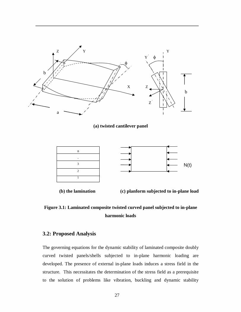
27
Z Y Y Y ' b X Z b Z '
a
(a) twisted cantilever panel
(b) the lamination (c) planform subjected to in-plane load
Figure 3.1: Laminated composite twisted curved panel subjected to in-plane
harmonic loads
3.2: Proposed Analysis
The governing equations for the dynamic stability of laminated composite doubly
curved twisted panels/shells subjected to in-plane harmonic loading are
developed. The presence of external in-plane loads induces a stress field in the
structure. This necessitates the determination of the stress field as a prerequisite
to the solution of problems like vibration, buckling and dynamic stability
1
2
.
n
3 N(t)
28
behaviour of pretwisted plates and shells. As the thickness of the structure is
relatively smaller, the determination of the stress field reduces to the solution of a
plane stress problem. The equation of motion represents a system of second order
differential equations with periodic coefficients of the Mathieu-Hill type. The
development of the regions of instability arises from Floquet’s theory and the
solution is obtained by Bolotin’s approach using finite element method. The
governing differential equations have been developed using the first order shear
deformation theory (FSDT). The assumptions made in the analysis are given
below.
3.2.1: Assumptions of the analysis
1. The analysis is linear, in line with previous studies on the dynamic stability of
untwisted panels (Bert and Birman [1988], Sahu and Datta [2003]) with a few
exceptions. This implies both linear constitutive relations (generalized Hooke’s
law for the material and linear kinematics) and small displacements to
accommodate small deformation theory.
2. The pretwisted curved panels have no initial imperfections. The consideration
for imperfections is less important for dynamic loading and is consistent with the
work of Bert and Birman [1988] for untwisted panels.
3. The straight line that is perpendicular to the neutral surface before deformation
remains straight but not normal after deformation (FSDT). The thickness of the
twisted panel is small compared with the principal radii of curvature. Normal
stress in the z-direction is neglected.
4. The loading on the panel is considered as axial with a simple harmonic
fluctuation with respect to time.
5. All damping effects are neglected.
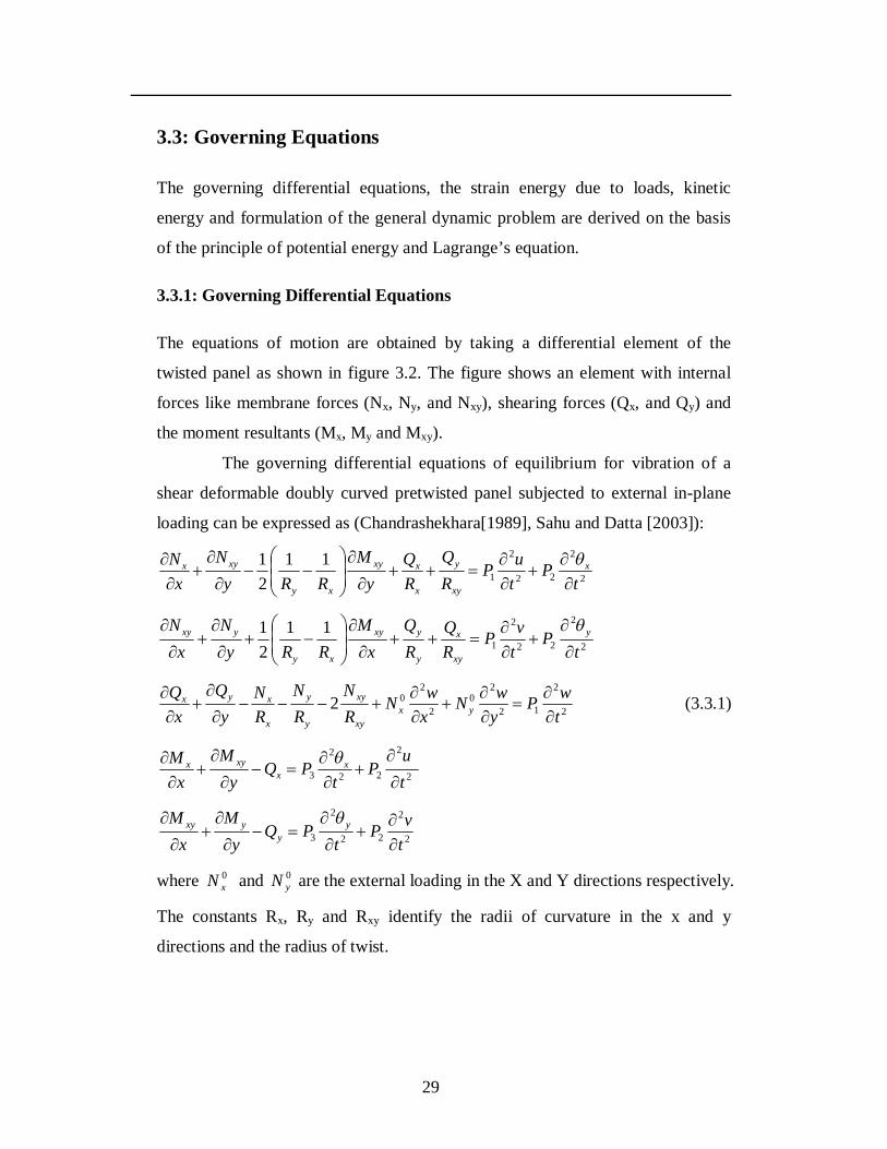
29
3.3: Governing Equations
The governing differential equations, the strain energy due to loads, kinetic
energy and formulation of the general dynamic problem are derived on the basis
of the principle of potential energy and Lagrange’s equation.
3.3.1: Governing Differential Equations
The equations of motion are obtained by taking a differential element of the
twisted panel as shown in figure 3.2. The figure shows an element with internal
forces like membrane forces (Nx, Ny, and Nxy), shearing forces (Qx, and Qy) and
the moment resultants (Mx, My and Mxy).
The governing differential equations of equilibrium for vibration of a
shear deformable doubly curved pretwisted panel subjected to external in-plane
loading can be expressed as (Chandrashekhara[1989], Sahu and Datta [2003]):
2
2
22
2
111
21
tP
tuP
RQ
RQ
yM
RRyN
xN x
xy
y
x
xxy
xy
xyx
2
2
22
2
111
21
tP
tvP
RQ
RQ
xM
RRyN
xN y
xy
x
y
yxy
xy
yxy
2
2
12
20
2
202
twP
ywN
xwN
RN
RN
RN
yQ
xQ
yxxy
xy
y
y
x
xyx
(3.3.1)
2
2
22
2
3 tu
Pt
PQy
Mx
M xx
xyx
2
2
22
2
3 tvP
tPQ
yM
xM y
yyxy
where 0xN and 0
yN are the external loading in the X and Y directions respectively.
The constants Rx, Ry and Rxy identify the radii of curvature in the x and y
directions and the radius of twist.
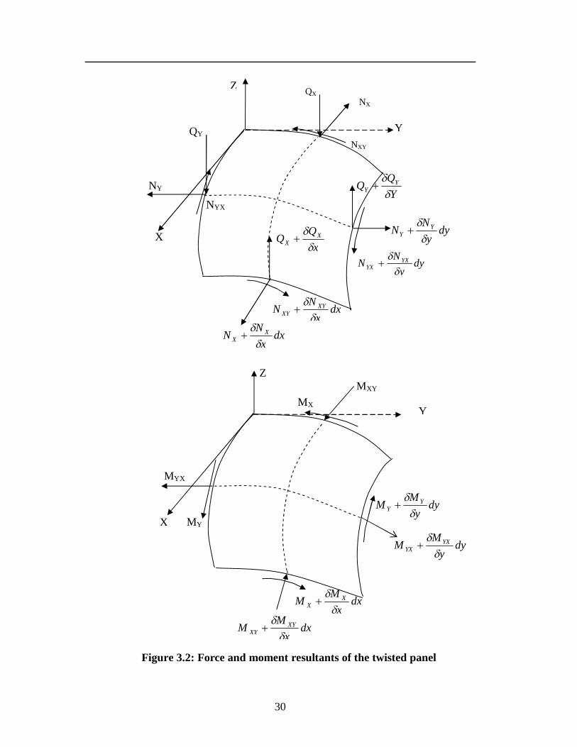
30
Figure 3.2: Force and moment resultants of the twisted panel
MX
dxx
MM XYXY
dxx
MM XX
MXY
MY
MYX
X
Z
dyy
MM YXYX
dyy
MM YY
Y
NXY
dxx
NN XYXY
dyy
NN YXYX
NYX
NY
QY
X
Y
Z
dxx
NN XX
xQQ X
X
QX NX
dyy
NN YY
YQQ Y
Y
31
dzzzPPPn
k
z
zk
k
k
),,1()(),,( 2
1321
1
where n = number of layers of the
laminated composite twisted curved panel, (ρ)k = mass density of kth layer from
the mid-plane.
3.4: Dynamic stability studies
The equation of motion for vibration of a laminated composite twisted cantilever
panel, subjected to in-plane loads can be expressed as:
0}]]{)[(][[}]{[ qKtNKqM ge (3.4.1)
‘q’ is the vector of degrees of freedom (u, v, w, x, y). The in-plane load ‘N (t)’
may be harmonic and can be expressed in the form:
tCosNNtN ts )( (3.4.2)
where sN is the static portion of the load N(t), tN is the amplitude of the dynamic
portion of N(t) and is the frequency of the excitation. Considering the static
and dynamic components of load as a function of the critical load,
crs NN , crt NN (3.4.3)
where α and β are the static and dynamic load factors respectively. Using equation
(3.4.3), the equation of motion for the twisted curved panel under periodic loads
in matrix form may be obtained as:
0}]{][][][[}]{[ qtCosKNKNKqM gcrgcre (3.4.4)
The above equation (3.4.4) represents a system of differential equations with
periodic coefficients of the Mathieu-Hill type. The development of regions of
instability arises from Floquet’s theory which establishes the existence of periodic
solutions of periods T and 2T. The boundaries of the primary instability regions
with period 2T, where T = 2 /Ω are of practical importance [Bolotin, 1964] and
the solution can be achieved in the form of the trigonometric series:
32
)]2/(}{)2/(}[{)(,..5,3,1
tkCosbtkSinatq kk
k
(3.4.5)
Putting this in equation (3.4.4) and if only the first term of the series is
considered, and equating coefficients of Sin Ωt/2 and Cos Ωt/2, the equation
(3.4.5) reduces to
0}]]{[4
][21][][[
2
qMKNKNK gcrgcre (3.4.6)
Equation (3.4.6) represents an eigenvalue problem for known values of , and
Ncr. The two conditions under the plus and minus sign correspond to the two
boundaries of the dynamic instability region. The eigenvalues are , which give
the boundary frequencies of the instability regions for given values of and . In
this analysis, the computed static buckling load of the panel is considered as the
reference load in line with many previous investigations (Ganapati et al. [1994],
Moorthy, Reddy and Plaut [1990]).
This equation represents a solution to a number of related problems:
(1)Free vibration: α = 0, β = 0 and ω = Ω/2
[[Ke] −ω² [M]]{q}=0 (3.4.7)
(2)Vibration with static axial load: β = 0 and ω = Ω/2
[[Ke] − αNcr [Kg] −ω² [M]]{q}=0 (3.4.8)
(3)Static stability: α = 1, β = 0, Ω = 0
[[Ke] −αNcr [Kg]] {q}=0 (3.4.9)
3.5: Energy Equations
The laminated composite doubly curved twisted panel is subjected to initial in-
plane edge loads 0xN , 0
yN and 0xyN . These in-plane loads cause in-plane stresses of
33
σx0, σy
0 and σxy0 and are a plane stress problem. The doubly curved panels with
the initial stresses undergo small lateral deformations. The total stresses at any
layer are the sum of the initial stresses plus the stresses due to bending and shear
deformation. The strain energy Uo due to initial in-plane stresses is written as
Uo = dAT }{}{21 00 (3.5.1)
where
x
vy
uy
vx
uTxyyx
T0000
0000 ,,][}{ (3.5.2)
and the stresses are
}]{[}{ 00 pD (3.5.3)
The strains can be expressed in terms of initial in-plane deformations u0, v0 as
}]{[}{ 00 qBP (3.5.4)
Substituting the values of stress and strain in the equation (3.5.1), we get
dAqBDBqU PPT
PT }]{][[][}{
21 00
0 (3.5.5)
The strain energy is expressed as
}]{[}{21 00
0 qKqU PT (3.5.6)
where
dABDBK PPT
PP ]][[][ (3.5.7)
Considering the prestressed state as the initial state, the strain energy stored due to
bending and shear deformation in the presence of initial stresses and neglecting
higher order terms is given by
U = U1+ U2 (3.5.8)
34
where U1 = Strain energy associated with bending with transverse shear and
U2 = Work done by the initial in-plane stresses and the nonlinear strain
dVDU lT
l }]]{[}[{21
1 (3.5.9)
where the strains can be expressed in terms of deformations as
}]{[}{ 0qBl (3.5.10)
and dVU nlT }]{}[{
21 0
2 (3.5.11)
The method of explicit integration is performed through the thickness of the
twisted panel and thus the generalized force and moment resultants can directly be
related to the strain components through the laminate stiffness. The kinetic energy
V of the curved panel can be derived as
dxdytt
ht
wt
vt
uhV yx
223222
122
(3.5.12)
The energies now can be written in matrix form as
U0 = }]{[}{21 qKq P
T
}]{[}{21
1 qKqU eT (3.5.13)
}]{[}{21
2 qKqU gT
}]{[}{21 qMqV T
where [Kp] = Plane stiffness matrix of the twisted panel
[Ke] = Bending stiffness matrix with shear deformation of the panel
[Kg] = Geometric stiffness or stress stiffness matrix of the twisted panel
[M] = Consistent mass matrix of the twisted panel
35
3.5.1: Formulation of Vibration and Static Stability problems
The governing equations for specified problems like plane stress, vibration and
static stability are derived as below:
1. Plane stress problem
Using the principle of stationary potential energy the equilibrium equation for
plane stress is expressed as
[KP]{q0}= {p0} (3.5.14)
2. Vibration with out in plane load
The governing equations for free vibrations are
[M] }{..q + [Ke] {q} = {0} (3.5.15)
3. Static stability or buckling
[[Ke] - N [Kg]]{q}= {0} (3.5.16)
The eigenvalues of the above equations give the natural frequencies and buckling
loads for different modes. The lowest values of frequency and buckling load are
termed as the fundamental natural frequency and fundamental critical load of the
twisted panel.
3.6: Finite Element Formulation
For problems involving complex geometrical and boundary conditions, analytical
methods are not easily adaptable and numerical methods like finite element
methods (FEM) are preferred. The finite element formulation is developed hereby
for the structural analysis of isotropic as well as composite twisted shell panels
using a curved shear deformable shell theory.
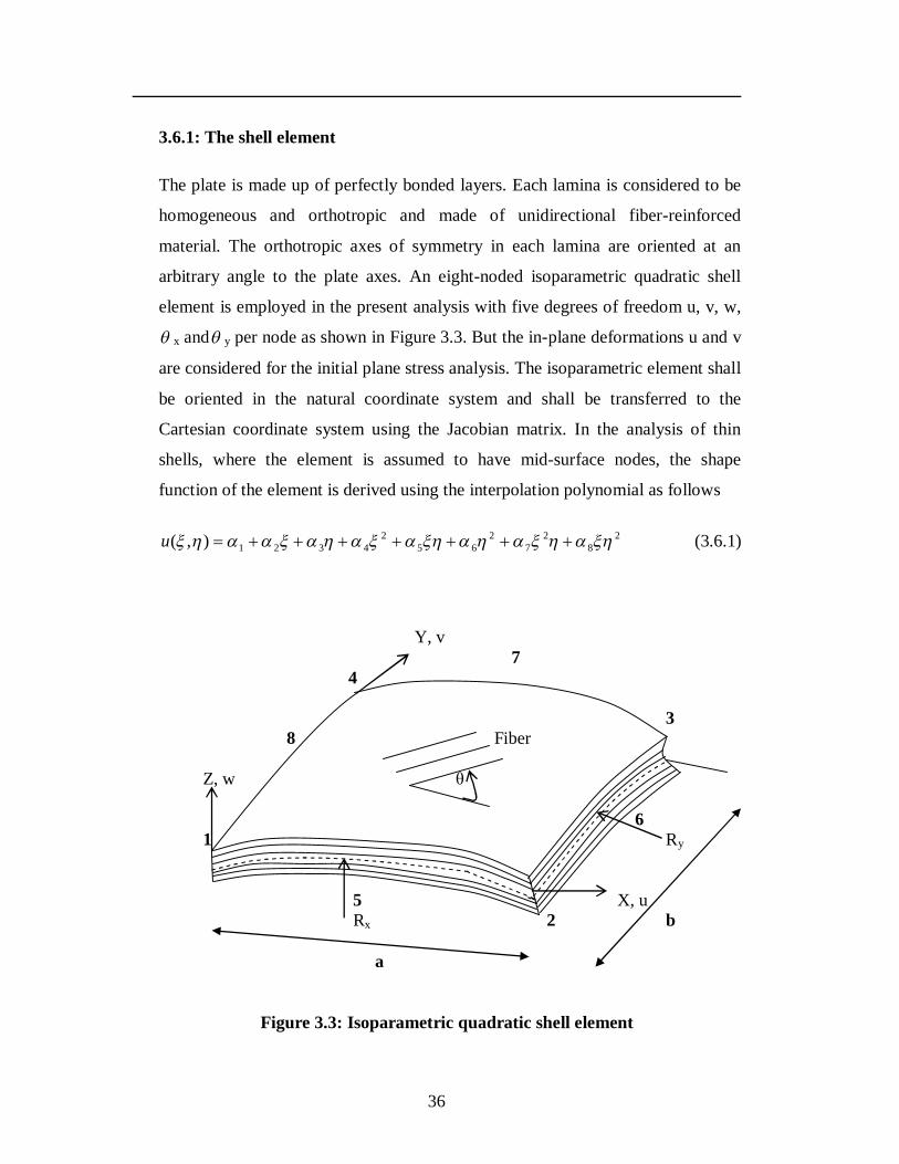
36
3.6.1: The shell element
The plate is made up of perfectly bonded layers. Each lamina is considered to be
homogeneous and orthotropic and made of unidirectional fiber-reinforced
material. The orthotropic axes of symmetry in each lamina are oriented at an
arbitrary angle to the plate axes. An eight-noded isoparametric quadratic shell
element is employed in the present analysis with five degrees of freedom u, v, w,
x and y per node as shown in Figure 3.3. But the in-plane deformations u and v
are considered for the initial plane stress analysis. The isoparametric element shall
be oriented in the natural coordinate system and shall be transferred to the
Cartesian coordinate system using the Jacobian matrix. In the analysis of thin
shells, where the element is assumed to have mid-surface nodes, the shape
function of the element is derived using the interpolation polynomial as follows
28
27
265
24321),( u (3.6.1)
Y, v 7 4 3 8 Fiber Z, w θ 6 1 Ry 5 X, u Rx 2 b a
Figure 3.3: Isoparametric quadratic shell element
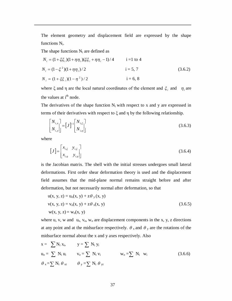
37
The element geometry and displacement field are expressed by the shape
functions Ni.
The shape functions Ni are defined as
4/)1)(1)(1( iiiiiN i =1 to 4
2/)1)(1( 2iiN i = 5, 7 (3.6.2)
2/)1)(1( 2 iiN i = 6, 8
where ξ and η are the local natural coordinates of the element and i and i are
the values at ith node.
The derivatives of the shape function Ni with respect to x and y are expressed in
terms of their derivatives with respect to ξ and η by the following relationship.
,
,1
,
,
i
i
yi
xi
NN
JNN
(3.6.3)
where
,,
,,
ii
ii
yxyx
J (3.6.4)
is the Jacobian matrix. The shell with the initial stresses undergoes small lateral
deformations. First order shear deformation theory is used and the displacement
field assumes that the mid-plane normal remains straight before and after
deformation, but not necessarily normal after deformation, so that
u(x, y, z) = uo(x, y) + z y (x, y)
v(x, y, z) = vo(x, y) + z x(x, y) (3.6.5)
w(x, y, z) = wo(x, y)
where u, v, w and uo, vo, wo are displacement components in the x, y, z directions
at any point and at the midsurface respectively. x and y are the rotations of the
midsurface normal about the x and y axes respectively. Also
x = Ni xi, y = Ni yi
uo = Ni ui vo = Ni vi wo = Ni wi (3.6.6)
x = Ni xi y = Ni yi
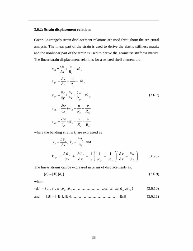
38
3.6.2: Strain displacement relations
Green-Lagrange’s strain displacement relations are used throughout the structural
analysis. The linear part of the strain is used to derive the elastic stiffness matrix
and the nonlinear part of the strain is used to derive the geometric stiffness matrix.
The linear strain displacement relations for a twisted shell element are:
xx
xl zkRw
xu
yyl zkRw
yv
y
xyxy
xyl zkR
wxv
yu
2 (3.6.7)
xyx
xxzl Rv
Ru
xw
xyy
yyzl Ru
Rv
yw
where the bending strains kj are expressed as
x
k xx
,
yk y
y
and
yu
xv
RRxyk
xy
yxxy
1121 (3.6.8)
The linear strains can be expressed in terms of displacements as,
}]{[}{ edB (3.6.9)
where
{de} = {u1, v1, w1, 1x , 1y ,……………………u8, v8, w8, 8x , 8y } (3.6.10)
and [B] = [[B1], [B2]………………………………. [B8]] (3.6.11)
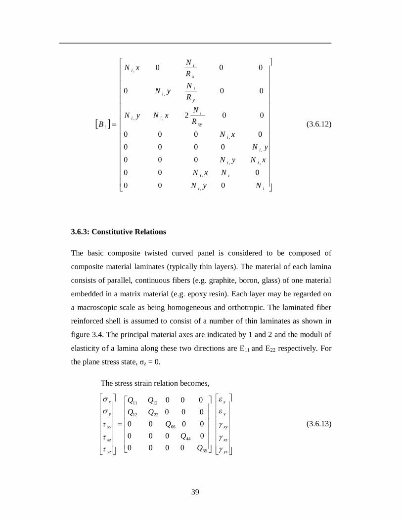
39
ii
ii
ii
i
i
xy
iii
y
ii
x
ii
i
NyNNxN
xNyNyN
xNRN
xNyN
RNyN
RNxN
B
000000
0000000
0000
002
000
000
,
,
,,
,
,
,,
,
,
(3.6.12)
3.6.3: Constitutive Relations
The basic composite twisted curved panel is considered to be composed of
composite material laminates (typically thin layers). The material of each lamina
consists of parallel, continuous fibers (e.g. graphite, boron, glass) of one material
embedded in a matrix material (e.g. epoxy resin). Each layer may be regarded on
a macroscopic scale as being homogeneous and orthotropic. The laminated fiber
reinforced shell is assumed to consist of a number of thin laminates as shown in
figure 3.4. The principal material axes are indicated by 1 and 2 and the moduli of
elasticity of a lamina along these two directions are E11 and E22 respectively. For
the plane stress state, σz = 0.
The stress strain relation becomes,
yz
xz
xy
y
x
yz
xz
xy
y
x
QQQQQ
55
44
66
2212
1211
000000000000000000
(3.6.13)
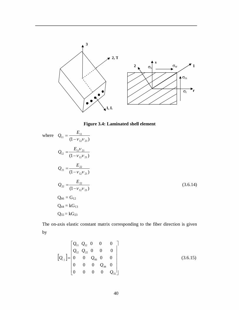
40
Figure 3.4: Laminated shell element
where )1( 2112
1111
EQ
)1( 2112
211112
EQ
)1( 2112
2221
EQ
)1( 2112
2222
EQ (3.6.14)
Q66 = G12
Q44 = kG13
Q55 = kG23
The on-axis elastic constant matrix corresponding to the fiber direction is given
by
55
44
66
2212
1211
000000000000000000
QQQQQ
Q ji (3.6.15)
σr
σrs
σsr σs 2 s
1
r
1, L
2, T
3
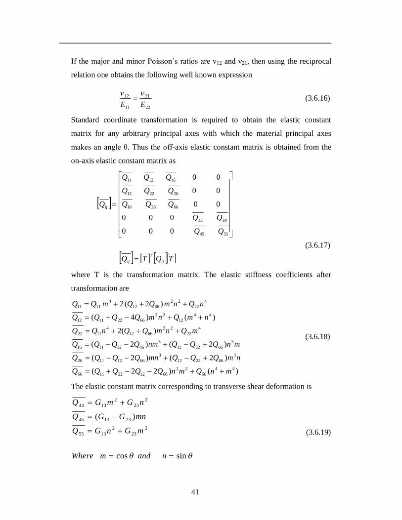
41
If the major and minor Poisson’s ratios are ν12 and ν21, then using the reciprocal
relation one obtains the following well known expression
22
21
11
12
EE
(3.6.16)
Standard coordinate transformation is required to obtain the elastic constant
matrix for any arbitrary principal axes with which the material principal axes
makes an angle θ. Thus the off-axis elastic constant matrix is obtained from the
on-axis elastic constant matrix as
TQTQ
QQQ
QQQ
QQQ
Q
ijT
ij
ij
5545
4544
662616
262212
161211
000
000
00
00
00
(3.6.17)
where T is the transformation matrix. The elastic stiffness coefficients after
transformation are
)()22(
)2()2(
)2()2(
)(2
)()4(
)2(2
4466
226612221166
3662212
366121126
3662212
366121116
422
226612
41122
4412
2266221112
422
226612
41111
mnQmnQQQQQ
nmQQQmnQQQQ
mnQQQnmQQQQ
mQnmQQnQQ
nmQnmQQQQ
nQnmQQmQQ
(3.6.18)
The elastic constant matrix corresponding to transverse shear deformation is
sincos
)(2
232
1355
231345
223
21344
nandmWhere
mGnGQ
mnGGQ
nGmGQ
(3.6.19)
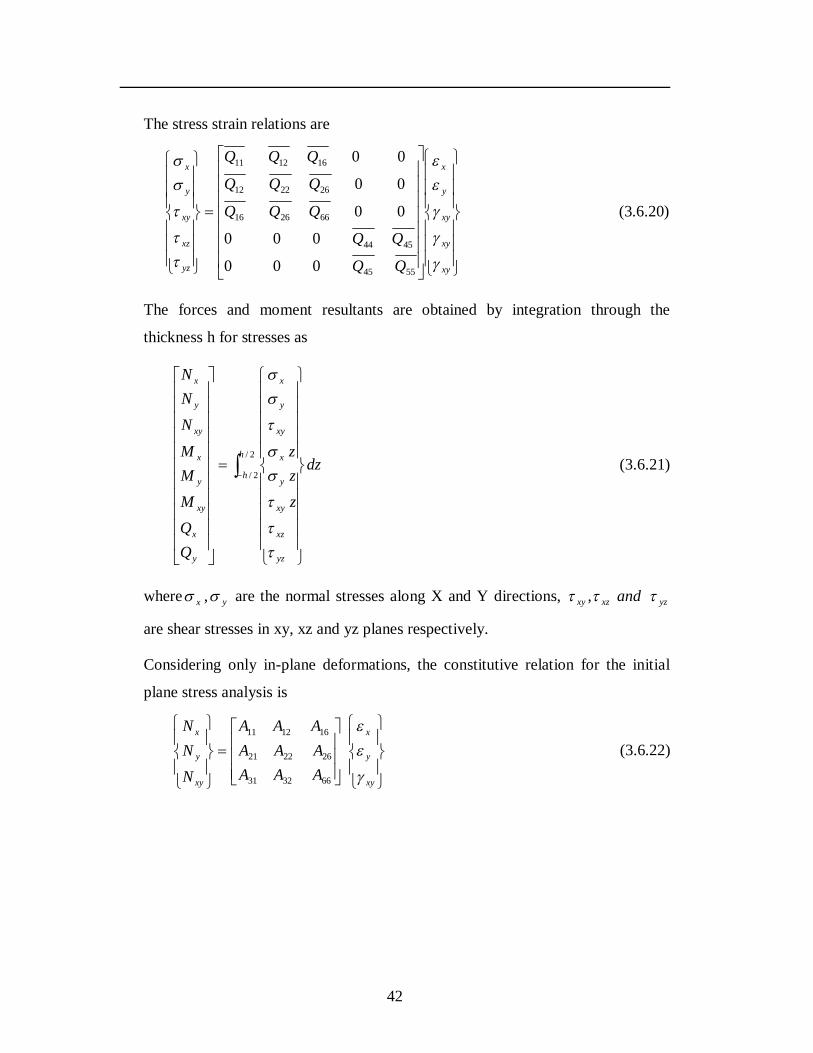
42
The stress strain relations are
xy
xy
xy
y
x
yz
xz
xy
y
x
QQQ
QQQ
QQQ
5545
4544
662616
262212
161211
000
000
00
00
00
(3.6.20)
The forces and moment resultants are obtained by integration through the
thickness h for stresses as
2/
2/
h
h
yz
xz
xy
y
x
xy
y
x
y
x
xy
y
x
xy
y
x
dz
zzz
QQMMMNNN
(3.6.21)
where x , y are the normal stresses along X and Y directions, yzxzxy and ,
are shear stresses in xy, xz and yz planes respectively.
Considering only in-plane deformations, the constitutive relation for the initial
plane stress analysis is
xy
y
x
xy
y
x
AAAAAAAAA
NNN
663231
262221
161211
(3.6.22)

43
The extensional stiffness for an isotropic material with material properties E and
are
)1(200
011
011
22
22
Eh
EhEh
EhEh
DP (3.6.23)
The constitutive relationships for bending with transverse shear of a doubly
curved shell becomes
yz
xz
xy
y
x
xy
y
x
y
x
xy
y
x
xy
y
x
kkk
SSSS
DDDBBBDDDBBBDDDBBBBBBAAABBBAAABBBAAA
QQMMMNNN
5545
4544
662616662616
262212262212
161211161211
161211662616
262212262221
161211161211
000000000000
00000000
0000
(3.6.24)
This can also be stated as
m
j
j
ij
ijij
ijij
i
i
i
kS
DBBA
QMN
000
0 (3.6.25)
or DF (3.6.26)
where Aij, Bij, Dij and Sij are the extensional, bending-stretching coupling, bending
and transverse shear stiffnesses. They may be defined as:
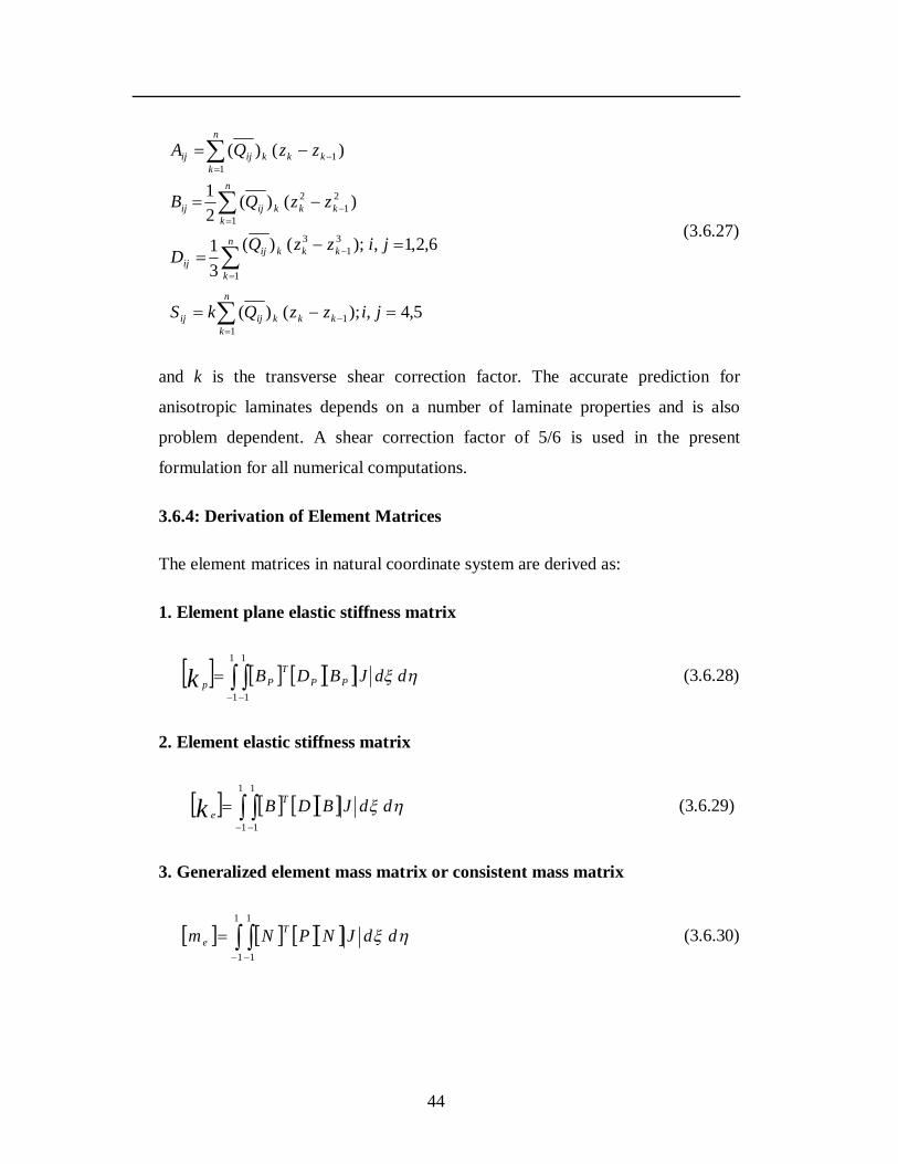
44
5,4,);()(
6,2,1,);()(31
)()(21
)()(
11
1
31
3
21
2
1
11
jizzQkS
jizzQD
zzQB
zzQA
kkk
n
kijij
n
k
kkkijij
kkk
n
kijij
kkk
n
kijij
(3.6.27)
and k is the transverse shear correction factor. The accurate prediction for
anisotropic laminates depends on a number of laminate properties and is also
problem dependent. A shear correction factor of 5/6 is used in the present
formulation for all numerical computations.
3.6.4: Derivation of Element Matrices
The element matrices in natural coordinate system are derived as:
1. Element plane elastic stiffness matrix
1
1
1
1
ddJBDB PPT
Ppk (3.6.28)
2. Element elastic stiffness matrix
1
1
1
1
ddJBDB Tek (3.6.29)
3. Generalized element mass matrix or consistent mass matrix
1
1
1
1
ddJNPNm Te (3.6.30)
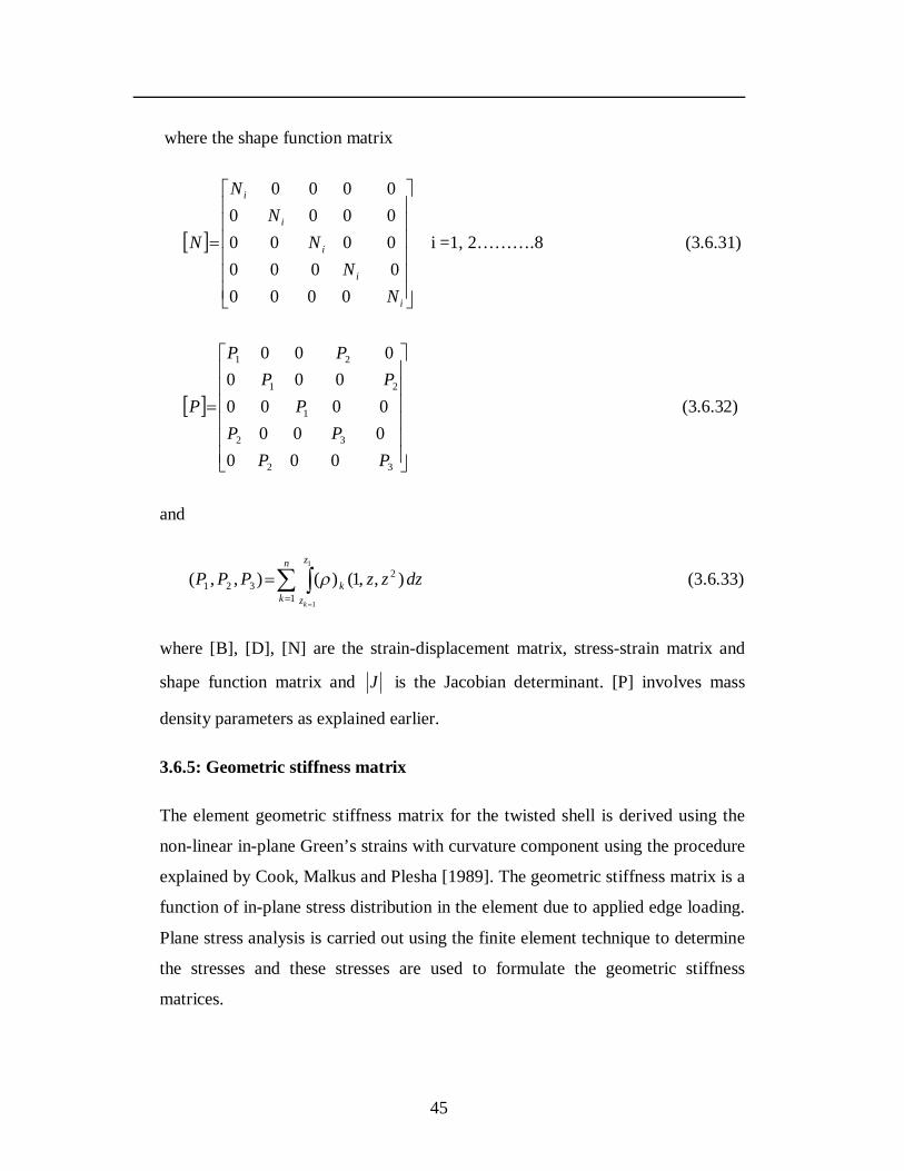
45
where the shape function matrix
i
i
i
i
i
NN
NN
N
N
00000000000000000000
i =1, 2……….8 (3.6.31)
32
32
1
21
21
0000000000
000000
PPPP
PPP
PP
P (3.6.32)
and
n
k
z
zk
k
dzzzPPP1
2321
1
1
),,1()(),,( (3.6.33)
where [B], [D], [N] are the strain-displacement matrix, stress-strain matrix and
shape function matrix and J is the Jacobian determinant. [P] involves mass
density parameters as explained earlier.
3.6.5: Geometric stiffness matrix
The element geometric stiffness matrix for the twisted shell is derived using the
non-linear in-plane Green’s strains with curvature component using the procedure
explained by Cook, Malkus and Plesha [1989]. The geometric stiffness matrix is a
function of in-plane stress distribution in the element due to applied edge loading.
Plane stress analysis is carried out using the finite element technique to determine
the stresses and these stresses are used to formulate the geometric stiffness
matrices.
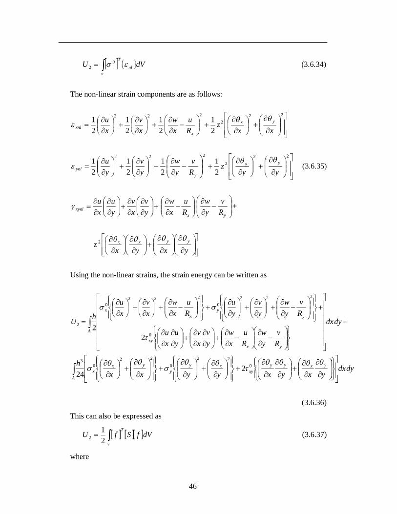
46
dVU nl
T
v
02 (3.6.34)
The non-linear strain components are as follows:
22
2222
21
21
21
21
xxz
Ru
xw
xv
xu yx
xxnl
22
2
222
21
21
21
21
yyz
Rv
yw
yv
yu yx
yynl
(3.6.35)
yv
xv
yu
xu
xynl
xRu
xw
yRv
yw +
z
yxyxyyxx 2
Using the non-linear strains, the strain energy can be written as
dydxyxyxyyxx
h
dydx
Rv
yw
Ru
xw
yv
xv
yu
xu
Rv
yw
yv
yu
Ru
xw
xv
xu
hU
yxyyxy
xyy
yxx
A
yxxy
yy
xx
A
022
022
03
0
2220
2220
2
224
22
(3.6.36)
This can also be expressed as
dVfSfUT
v
21
2 (3.6.37)
where
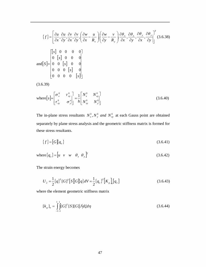
47
T
yyxx
yx yxyxRv
yw
Ru
xw
yv
xv
yu
xuf
,,,,,,,,, (3.6.38)
and
ss
ss
s
S
00000000000000000000
(3.6.39)
where
00
00
0
001
yxy
xyx
oyxy
xyx
NN
NN
hs
(3.6.40)
The in-plane stress resultants 000 , xyyx NandNN at each Gauss point are obtained
separately by plane stress analysis and the geometric stiffness matrix is formed for
these stress resultants.
eqGf (3.6.41)
where Tyxe wvuq (3.6.42)
The strain energy becomes
eegT
eTT qKqdVqGSGqU
21][
21
2 (3.6.43)
where the element geometric stiffness matrix
ddJGSGk Teg
1
1
1
1
]][[][][ (3.6.44)
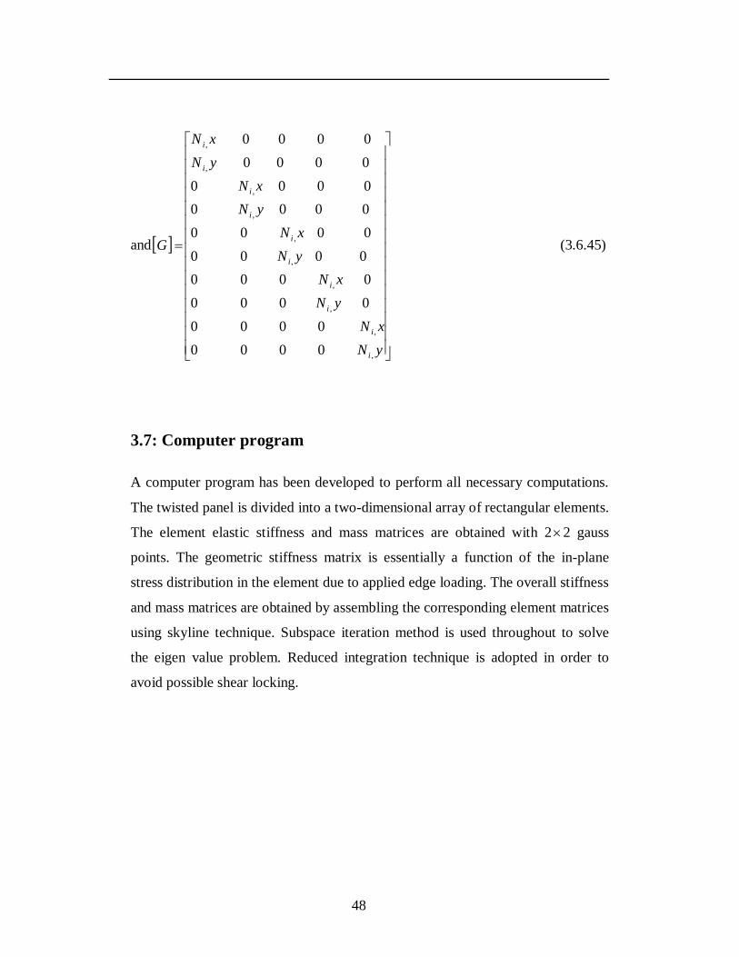
48
and
yNxN
yNxN
yNxN
yNxN
yNxN
G
i
i
i
i
i
i
i
i
i
i
,
,
,
,
,
,
,
,
,
,
00000000
00000000
000000000000000000000000
(3.6.45)
3.7: Computer program
A computer program has been developed to perform all necessary computations.
The twisted panel is divided into a two-dimensional array of rectangular elements.
The element elastic stiffness and mass matrices are obtained with 22 gauss
points. The geometric stiffness matrix is essentially a function of the in-plane
stress distribution in the element due to applied edge loading. The overall stiffness
and mass matrices are obtained by assembling the corresponding element matrices
using skyline technique. Subspace iteration method is used throughout to solve
the eigen value problem. Reduced integration technique is adopted in order to
avoid possible shear locking.
49
CHAPTER 4
RESULTS AND DISCUSSIONS
4.1: Introduction
The present chapter deals with the results of the analyses of the vibration,
buckling and parametric resonance characteristics of homogeneous and laminated
composite twisted cantilever panels using the formulation given in the previous
chapter. As explained, the eight-node isoparametric quadratic shell element is
used to develop the finite element procedure. The first order shear deformation
theory is used to model the twisted panels considering the effects of transverse
shear deformation and rotary inertia. The stability characteristics of homogeneous
and laminated composite pretwisted cantilever panels subjected to in-plane loads
are studied. The parametric instability studies are carried out for isotropic and
laminated composite pretwisted panels subjected to in-plane periodic loads with
static component of load to consider the effect of various parameters. The studies
in this chapter are presented as follows:
Convergence study
Comparison with previous studies
Numerical results
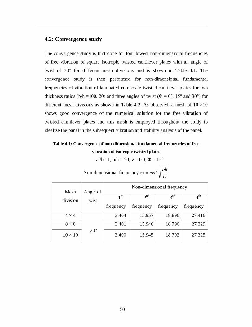
50
4.2: Convergence study
The convergence study is first done for four lowest non-dimensional frequencies
of free vibration of square isotropic twisted cantilever plates with an angle of
twist of 30° for different mesh divisions and is shown in Table 4.1. The
convergence study is then performed for non-dimensional fundamental
frequencies of vibration of laminated composite twisted cantilever plates for two
thickness ratios (b/h =100, 20) and three angles of twist (Φ = 0°, 15° and 30°) for
different mesh divisions as shown in Table 4.2. As observed, a mesh of 10 ×10
shows good convergence of the numerical solution for the free vibration of
twisted cantilever plates and this mesh is employed throughout the study to
idealize the panel in the subsequent vibration and stability analysis of the panel.
Table 4.1: Convergence of non-dimensional fundamental frequencies of free vibration of isotropic twisted plates
a /b =1, b/h = 20, ν = 0.3, Φ = 15°
Non-dimensional frequency Dha
2
Mesh
division
Angle of
twist
Non-dimensional frequency
1st
frequency
2nd
frequency
3rd
frequency
4th
frequency
4 × 4
30°
3.404 15.957 18.896 27.416
8 × 8 3.401 15.946 18.796 27.329
10 × 10 3.400 15.945 18.792 27.325
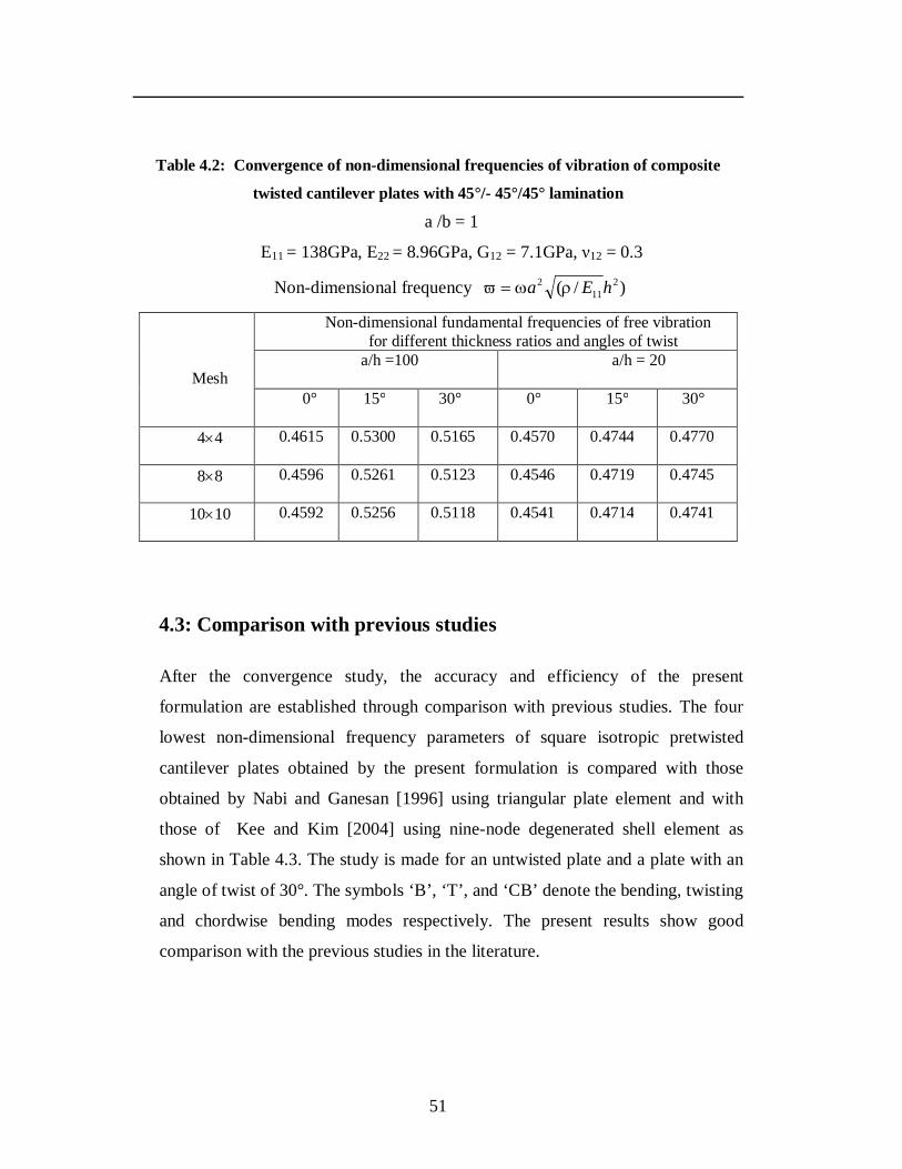
51
Table 4.2: Convergence of non-dimensional frequencies of vibration of composite
twisted cantilever plates with 45°/- 45°/45° lamination
a /b = 1
E11 = 138GPa, E22 = 8.96GPa, G12 = 7.1GPa, ν12 = 0.3
Non-dimensional frequency )/( 211
2 hEa
Mesh
Non-dimensional fundamental frequencies of free vibration for different thickness ratios and angles of twist
a/h =100
a/h = 20
0° 15° 30° 0° 15° 30°
44 0.4615 0.5300 0.5165 0.4570 0.4744 0.4770
88 0.4596 0.5261 0.5123 0.4546 0.4719 0.4745
1010 0.4592 0.5256 0.5118 0.4541 0.4714 0.4741
4.3: Comparison with previous studies
After the convergence study, the accuracy and efficiency of the present
formulation are established through comparison with previous studies. The four
lowest non-dimensional frequency parameters of square isotropic pretwisted
cantilever plates obtained by the present formulation is compared with those
obtained by Nabi and Ganesan [1996] using triangular plate element and with
those of Kee and Kim [2004] using nine-node degenerated shell element as
shown in Table 4.3. The study is made for an untwisted plate and a plate with an
angle of twist of 30°. The symbols ‘B’, ‘T’, and ‘CB’ denote the bending, twisting
and chordwise bending modes respectively. The present results show good
comparison with the previous studies in the literature.
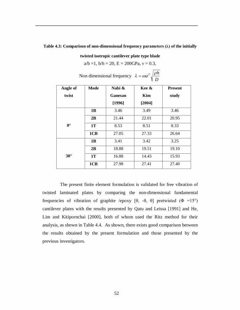
52
Table 4.3: Comparison of non-dimensional frequency parameters (λ) of the initially
twisted isotropic cantilever plate type blade
a/b =1, b/h = 20, E = 200GPa, ν = 0.3,
Non dimensional frequency Dha
2
Angle of
twist
Mode Nabi &
Ganesan
[1996]
Kee &
Kim
[2004]
Present
study
0°
1B 3.46 3.49 3.46
2B 21.44 22.01 20.95
1T 8.53 8.51 8.33
1CB 27.05 27.33 26.64
30°
1B 3.41 3.42 3.25
2B 18.88 19.51 19.10
1T 16.88 14.43 15.93
1CB 27.98 27.41 27.40
The present finite element formulation is validated for free vibration of
twisted laminated plates by comparing the non-dimensional fundamental
frequencies of vibration of graphite /epoxy [θ, -θ, θ] pretwisted (Φ =15°)
cantilever plates with the results presented by Qatu and Leissa [1991] and He,
Lim and Kitipornchai [2000], both of whom used the Ritz method for their
analysis, as shown in Table 4.4. As shown, there exists good comparison between
the results obtained by the present formulation and those presented by the
previous investigators.
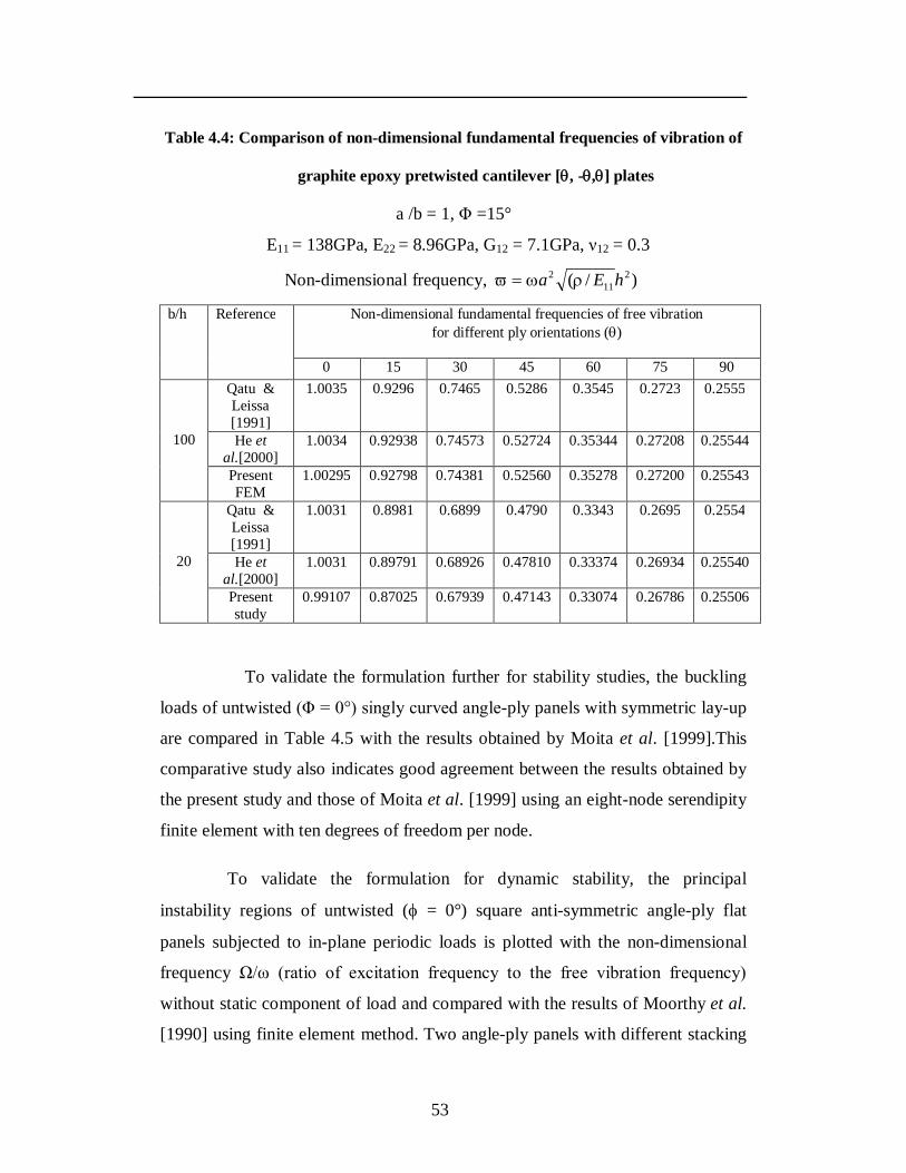
53
Table 4.4: Comparison of non-dimensional fundamental frequencies of vibration of
graphite epoxy pretwisted cantilever [, -,] plates
a /b = 1, Φ =15°
E11 = 138GPa, E22 = 8.96GPa, G12 = 7.1GPa, ν12 = 0.3
Non-dimensional frequency, )/( 211
2 hEa
b/h Reference Non-dimensional fundamental frequencies of free vibration for different ply orientations ()
0 15 30 45 60 75 90
100
Qatu & Leissa [1991]
1.0035 0.9296 0.7465 0.5286 0.3545 0.2723 0.2555
He et al.[2000]
1.0034 0.92938 0.74573 0.52724 0.35344 0.27208 0.25544
Present FEM
1.00295 0.92798 0.74381 0.52560 0.35278 0.27200 0.25543
20
Qatu & Leissa [1991]
1.0031 0.8981 0.6899 0.4790 0.3343 0.2695 0.2554
He et al.[2000]
1.0031 0.89791 0.68926 0.47810 0.33374 0.26934 0.25540
Present study
0.99107 0.87025 0.67939 0.47143 0.33074 0.26786 0.25506
To validate the formulation further for stability studies, the buckling
loads of untwisted (Φ = 0°) singly curved angle-ply panels with symmetric lay-up
are compared in Table 4.5 with the results obtained by Moita et al. [1999].This
comparative study also indicates good agreement between the results obtained by
the present study and those of Moita et al. [1999] using an eight-node serendipity
finite element with ten degrees of freedom per node.
To validate the formulation for dynamic stability, the principal
instability regions of untwisted ( = 0°) square anti-symmetric angle-ply flat
panels subjected to in-plane periodic loads is plotted with the non-dimensional
frequency Ω/ω (ratio of excitation frequency to the free vibration frequency)
without static component of load and compared with the results of Moorthy et al.
[1990] using finite element method. Two angle-ply panels with different stacking
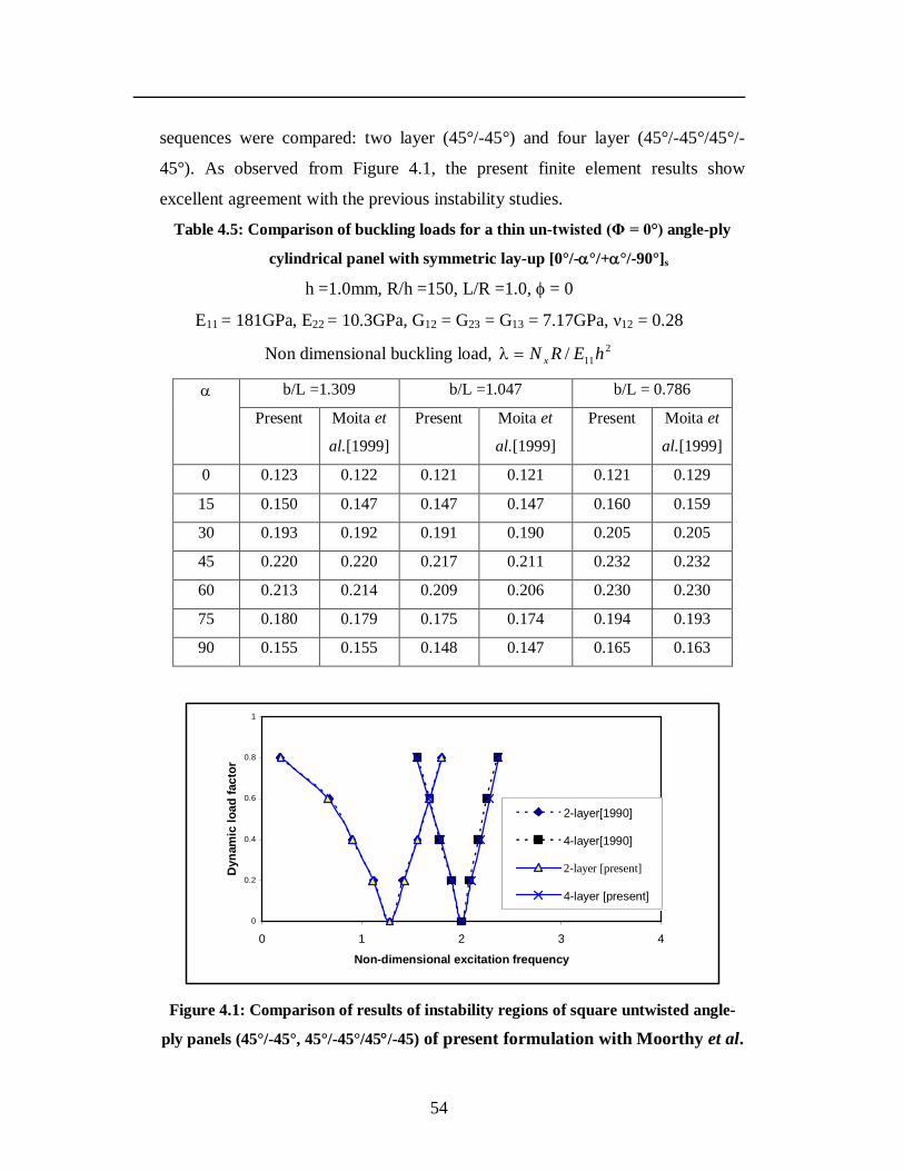
54
sequences were compared: two layer (45°/-45°) and four layer (45°/-45°/45°/-
45°). As observed from Figure 4.1, the present finite element results show
excellent agreement with the previous instability studies.
Table 4.5: Comparison of buckling loads for a thin un-twisted (Φ = 0°) angle-ply
cylindrical panel with symmetric lay-up [0°/-°/+°/-90°]s
h =1.0mm, R/h =150, L/R =1.0, = 0
E11 = 181GPa, E22 = 10.3GPa, G12 = G23 = G13 = 7.17GPa, ν12 = 0.28
Non dimensional buckling load, 211/ hERN x
b/L =1.309 b/L =1.047 b/L = 0.786
Present Moita et
al.[1999]
Present Moita et
al.[1999]
Present Moita et
al.[1999]
0 0.123 0.122 0.121 0.121 0.121 0.129
15 0.150 0.147 0.147 0.147 0.160 0.159
30 0.193 0.192 0.191 0.190 0.205 0.205
45 0.220 0.220 0.217 0.211 0.232 0.232
60 0.213 0.214 0.209 0.206 0.230 0.230
75 0.180 0.179 0.175 0.174 0.194 0.193
90 0.155 0.155 0.148 0.147 0.165 0.163
0
0.2
0.4
0.6
0.8
1
0 1 2 3 4
Non-dimensional excitation frequency
Dyn
amic
load
fact
or
2-layer[1990]
4-layer[1990]
2-layer [present]
4-layer [present]
Figure 4.1: Comparison of results of instability regions of square untwisted angle-
ply panels (45°/-45°, 45°/-45°/45/-45) of present formulation with Moorthy et al.
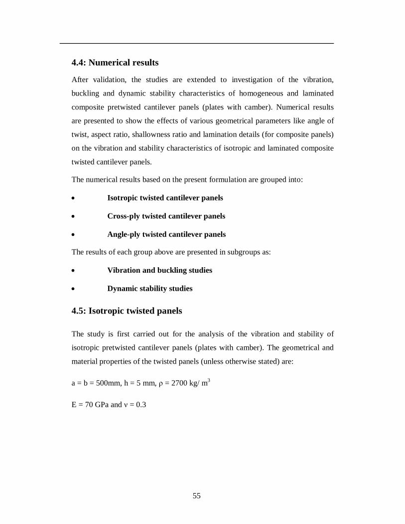
55
4.4: Numerical results
After validation, the studies are extended to investigation of the vibration,
buckling and dynamic stability characteristics of homogeneous and laminated
composite pretwisted cantilever panels (plates with camber). Numerical results
are presented to show the effects of various geometrical parameters like angle of
twist, aspect ratio, shallowness ratio and lamination details (for composite panels)
on the vibration and stability characteristics of isotropic and laminated composite
twisted cantilever panels.
The numerical results based on the present formulation are grouped into:
Isotropic twisted cantilever panels
Cross-ply twisted cantilever panels
Angle-ply twisted cantilever panels
The results of each group above are presented in subgroups as:
Vibration and buckling studies
Dynamic stability studies
4.5: Isotropic twisted panels
The study is first carried out for the analysis of the vibration and stability of
isotropic pretwisted cantilever panels (plates with camber). The geometrical and
material properties of the twisted panels (unless otherwise stated) are:
a = b = 500mm, h = 5 mm, ρ = 2700 kg/ m3
E = 70 GPa and ν = 0.3
56
4.5.1: Non-dimensionalization of parameters
The non-dimensionalization of the different parameters is carried out as follows:
Non-dimensional frequency Dha
2
Non-dimensional buckling load DbN x
2
where D = 2
3
112 Eh
The non-dimensional excitation frequency )/(2 Dha (unless otherwise
stated) is used throughout the dynamic instability studies, where is the
excitation frequency in radians/second.
4.5.2: Boundary conditions
The clamped (C) boundary condition of the isotropic twisted panel using the first
order shear deformation theory is:
u = v = w = x = y = 0 at the left edge.
4.5.3: Vibration and buckling studies
The first four frequencies of vibration of an isotropic twisted cantilever plate are
presented in Table 4.6 for varying angles of twist. Introduction of an angle of
twist of 10° to the untwisted plate is seen to reduce the fundamental frequency
parameter by 0.5%. It is also seen that as the angle of twist increases, the
fundamental frequency parameter decreases. When the angle of twist of the plate
is 30°, the fundamental frequency parameter is lesser by 5.7% as compared to the
untwisted plate. The 2nd frequency in bending mode decreases with the increasing
angle of twist except the additional twisting mode for untwisted plates. The 3rd
and the 4th frequency parameter increase with increase in the twisting angle.
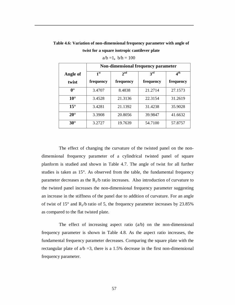
57
Table 4.6: Variation of non-dimensional frequency parameter with angle of
twist for a square isotropic cantilever plate
a/b =1, b/h = 100
Angle of
twist
Non-dimensional frequency parameter
1st
frequency
2nd
frequency
3rd
frequency
4th
frequency
0° 3.4707 8.4838 21.2714 27.1573
10° 3.4528 21.3136 22.3154 31.2619
15° 3.4281 21.1392 31.4238 35.9028
20° 3.3908 20.8056 39.9847 41.6632
30° 3.2727 19.7639 54.7100 57.8757
The effect of changing the curvature of the twisted panel on the non-
dimensional frequency parameter of a cylindrical twisted panel of square
planform is studied and shown in Table 4.7. The angle of twist for all further
studies is taken as 15°. As observed from the table, the fundamental frequency
parameter decreases as the Ry/b ratio increases. Also introduction of curvature to
the twisted panel increases the non-dimensional frequency parameter suggesting
an increase in the stiffness of the panel due to addition of curvature. For an angle
of twist of 15° and Ry/b ratio of 5, the frequency parameter increases by 23.85%
as compared to the flat twisted plate.
The effect of increasing aspect ratio (a/b) on the non-dimensional
frequency parameter is shown in Table 4.8. As the aspect ratio increases, the
fundamental frequency parameter decreases. Comparing the square plate with the
rectangular plate of a/b =3, there is a 1.5% decrease in the first non-dimensional
frequency parameter.
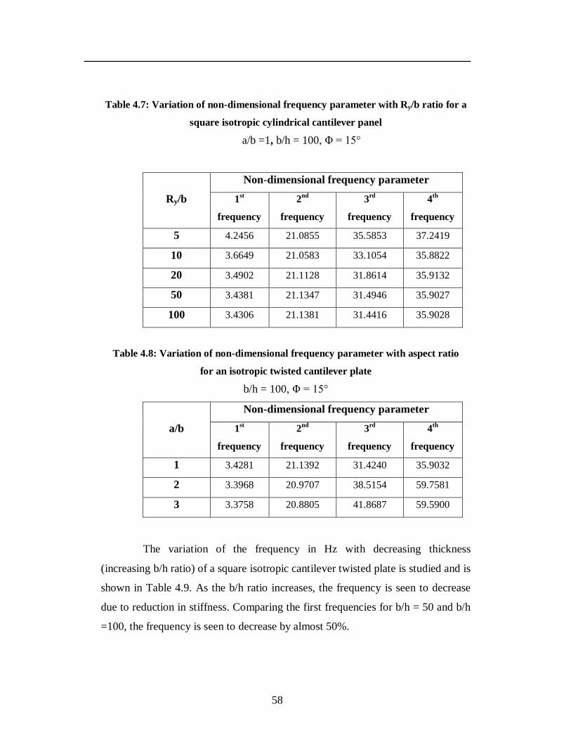
58
Table 4.7: Variation of non-dimensional frequency parameter with Ry/b ratio for a
square isotropic cylindrical cantilever panel
a/b =1, b/h = 100, Φ = 15°
Ry/b
Non-dimensional frequency parameter
1st
frequency
2nd
frequency
3rd
frequency
4th
frequency
5 4.2456 21.0855 35.5853 37.2419
10 3.6649 21.0583 33.1054 35.8822
20 3.4902 21.1128 31.8614 35.9132
50 3.4381 21.1347 31.4946 35.9027
100 3.4306 21.1381 31.4416 35.9028
Table 4.8: Variation of non-dimensional frequency parameter with aspect ratio
for an isotropic twisted cantilever plate
b/h = 100, Φ = 15°
a/b
Non-dimensional frequency parameter
1st
frequency
2nd
frequency
3rd
frequency
4th
frequency
1 3.4281 21.1392 31.4240 35.9032
2 3.3968 20.9707 38.5154 59.7581
3 3.3758 20.8805 41.8687 59.5900
The variation of the frequency in Hz with decreasing thickness
(increasing b/h ratio) of a square isotropic cantilever twisted plate is studied and is
shown in Table 4.9. As the b/h ratio increases, the frequency is seen to decrease
due to reduction in stiffness. Comparing the first frequencies for b/h = 50 and b/h
=100, the frequency is seen to decrease by almost 50%.
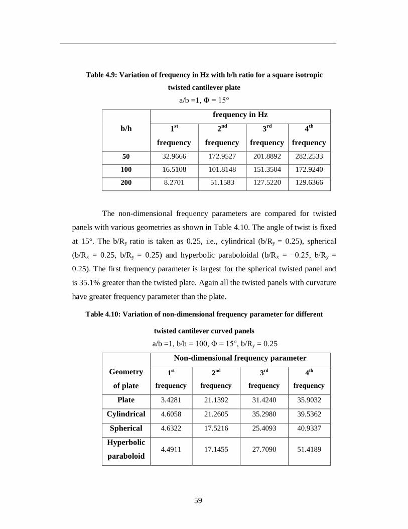
59
Table 4.9: Variation of frequency in Hz with b/h ratio for a square isotropic
twisted cantilever plate
a/b =1, Φ = 15°
b/h
frequency in Hz
1st
frequency
2nd
frequency
3rd
frequency
4th
frequency
50 32.9666 172.9527 201.8892 282.2533
100 16.5108 101.8148 151.3504 172.9240
200 8.2701 51.1583 127.5220 129.6366
The non-dimensional frequency parameters are compared for twisted
panels with various geometries as shown in Table 4.10. The angle of twist is fixed
at 15°. The b/Ry ratio is taken as 0.25, i.e., cylindrical (b/Ry = 0.25), spherical
(b/Rx = 0.25, b/Ry = 0.25) and hyperbolic paraboloidal (b/Rx = −0.25, b/Ry =
0.25). The first frequency parameter is largest for the spherical twisted panel and
is 35.1% greater than the twisted plate. Again all the twisted panels with curvature
have greater frequency parameter than the plate.
Table 4.10: Variation of non-dimensional frequency parameter for different
twisted cantilever curved panels
a/b =1, b/h = 100, Φ = 15°, b/Ry = 0.25
Geometry
of plate
Non-dimensional frequency parameter
1st
frequency
2nd
frequency
3rd
frequency
4th
frequency
Plate 3.4281 21.1392 31.4240 35.9032
Cylindrical 4.6058 21.2605 35.2980 39.5362
Spherical 4.6322 17.5216 25.4093 40.9337
Hyperbolic
paraboloid 4.4911 17.1455 27.7090 51.4189
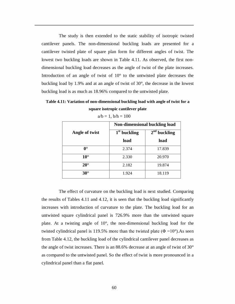
60
The study is then extended to the static stability of isotropic twisted
cantilever panels. The non-dimensional buckling loads are presented for a
cantilever twisted plate of square plan form for different angles of twist. The
lowest two buckling loads are shown in Table 4.11. As observed, the first non-
dimensional buckling load decreases as the angle of twist of the plate increases.
Introduction of an angle of twist of 10° to the untwisted plate decreases the
buckling load by 1.9% and at an angle of twist of 30°, the decrease in the lowest
buckling load is as much as 18.96% compared to the untwisted plate.
Table 4.11: Variation of non-dimensional buckling load with angle of twist for a
square isotropic cantilever plate
a/b = 1, b/h = 100
Angle of twist
Non-dimensional buckling load
1st buckling
load
2nd buckling
load
0° 2.374 17.839
10° 2.330 20.970
20° 2.182 19.874
30° 1.924 18.119
The effect of curvature on the buckling load is next studied. Comparing
the results of Tables 4.11 and 4.12, it is seen that the buckling load significantly
increases with introduction of curvature to the plate. The buckling load for an
untwisted square cylindrical panel is 726.9% more than the untwisted square
plate. At a twisting angle of 10°, the non-dimensional buckling load for the
twisted cylindrical panel is 119.5% more than the twisted plate (Φ =10°).As seen
from Table 4.12, the buckling load of the cylindrical cantilever panel decreases as
the angle of twist increases. There is an 88.6% decrease at an angle of twist of 30°
as compared to the untwisted panel. So the effect of twist is more pronounced in a
cylindrical panel than a flat panel.
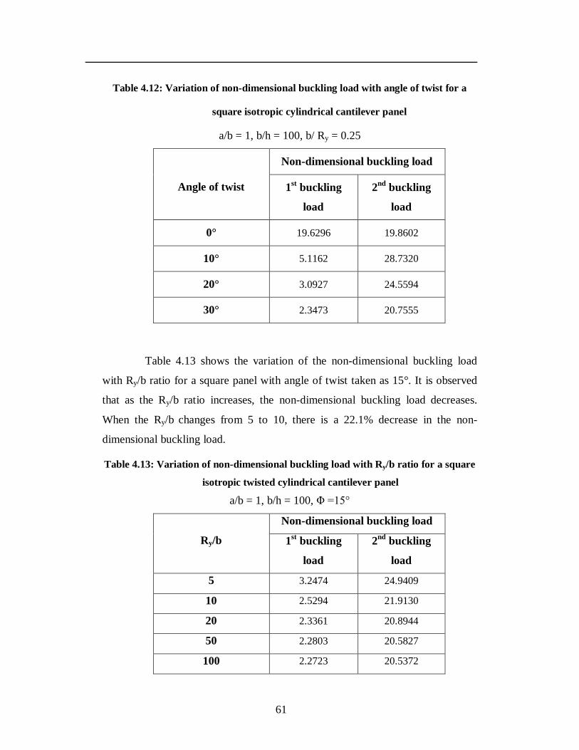
61
Table 4.12: Variation of non-dimensional buckling load with angle of twist for a
square isotropic cylindrical cantilever panel
a/b = 1, b/h = 100, b/ Ry = 0.25
Angle of twist
Non-dimensional buckling load
1st buckling
load
2nd buckling
load
0° 19.6296 19.8602
10° 5.1162 28.7320
20° 3.0927 24.5594
30° 2.3473 20.7555
Table 4.13 shows the variation of the non-dimensional buckling load
with Ry/b ratio for a square panel with angle of twist taken as 15°. It is observed
that as the Ry/b ratio increases, the non-dimensional buckling load decreases.
When the Ry/b changes from 5 to 10, there is a 22.1% decrease in the non-
dimensional buckling load.
Table 4.13: Variation of non-dimensional buckling load with Ry/b ratio for a square
isotropic twisted cylindrical cantilever panel
a/b = 1, b/h = 100, Φ =15°
Ry/b
Non-dimensional buckling load
1st buckling
load
2nd buckling
load
5 3.2474 24.9409
10 2.5294 21.9130
20 2.3361 20.8944
50 2.2803 20.5827
100 2.2723 20.5372
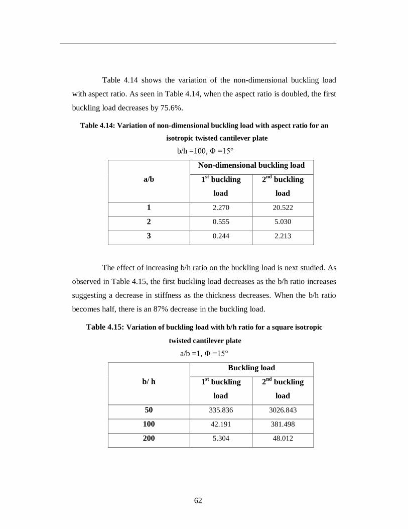
62
Table 4.14 shows the variation of the non-dimensional buckling load
with aspect ratio. As seen in Table 4.14, when the aspect ratio is doubled, the first
buckling load decreases by 75.6%.
Table 4.14: Variation of non-dimensional buckling load with aspect ratio for an
isotropic twisted cantilever plate
b/h =100, Φ =15°
a/b
Non-dimensional buckling load
1st buckling
load
2nd buckling
load
1 2.270 20.522
2 0.555 5.030
3 0.244 2.213
The effect of increasing b/h ratio on the buckling load is next studied. As
observed in Table 4.15, the first buckling load decreases as the b/h ratio increases
suggesting a decrease in stiffness as the thickness decreases. When the b/h ratio
becomes half, there is an 87% decrease in the buckling load.
Table 4.15: Variation of buckling load with b/h ratio for a square isotropic
twisted cantilever plate
a/b =1, Φ =15°
b/ h
Buckling load
1st buckling
load
2nd buckling
load
50 335.836 3026.843
100 42.191 381.498
200 5.304 48.012
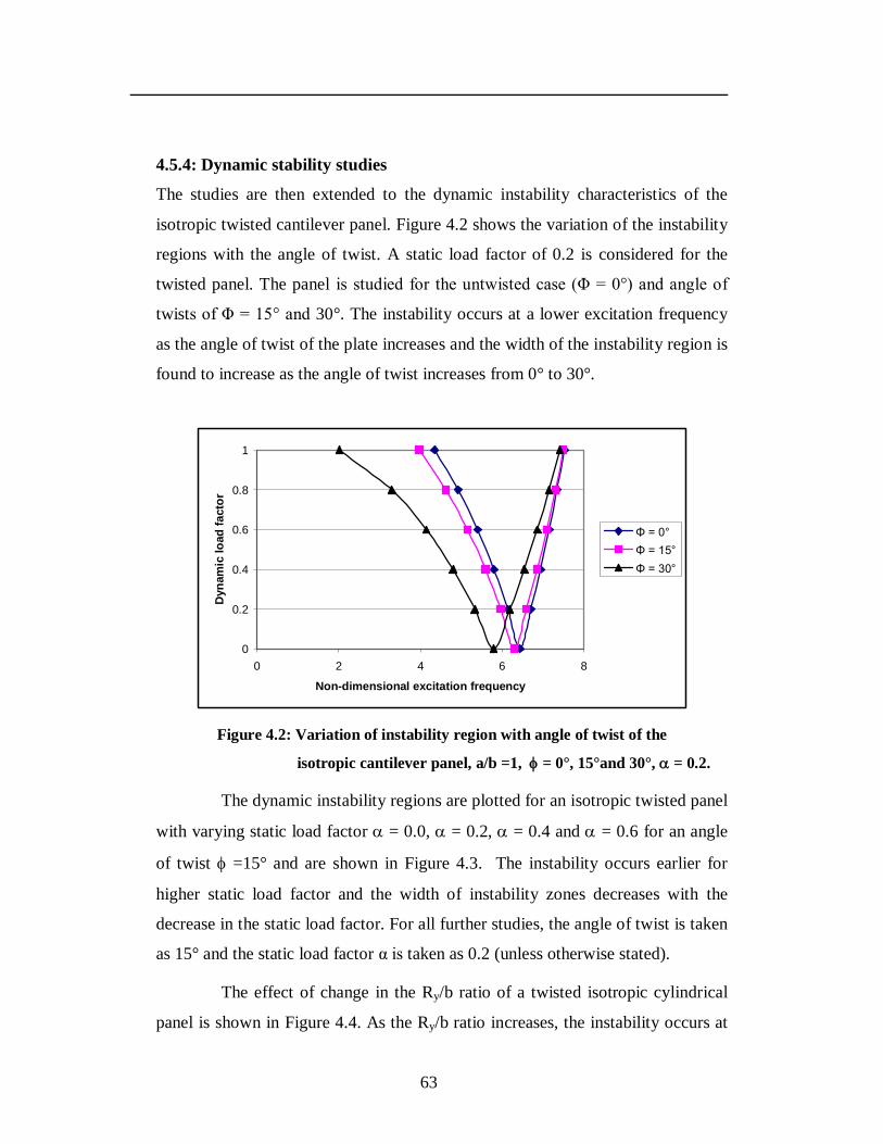
63
4.5.4: Dynamic stability studies
The studies are then extended to the dynamic instability characteristics of the
isotropic twisted cantilever panel. Figure 4.2 shows the variation of the instability
regions with the angle of twist. A static load factor of 0.2 is considered for the
twisted panel. The panel is studied for the untwisted case (Φ = 0°) and angle of
twists of Φ = 15° and 30°. The instability occurs at a lower excitation frequency
as the angle of twist of the plate increases and the width of the instability region is
found to increase as the angle of twist increases from 0° to 30°.
0
0.2
0.4
0.6
0.8
1
0 2 4 6 8
Non-dimensional excitation frequency
Dyn
amic
load
fact
or
Φ = 0°Φ = 15°Φ = 30°
Figure 4.2: Variation of instability region with angle of twist of the
isotropic cantilever panel, a/b =1, = 0°, 15°and 30°, = 0.2.
The dynamic instability regions are plotted for an isotropic twisted panel
with varying static load factor = 0.0, = 0.2, = 0.4 and = 0.6 for an angle
of twist =15° and are shown in Figure 4.3. The instability occurs earlier for
higher static load factor and the width of instability zones decreases with the
decrease in the static load factor. For all further studies, the angle of twist is taken
as 15° and the static load factor α is taken as 0.2 (unless otherwise stated).
The effect of change in the Ry/b ratio of a twisted isotropic cylindrical
panel is shown in Figure 4.4. As the Ry/b ratio increases, the instability occurs at
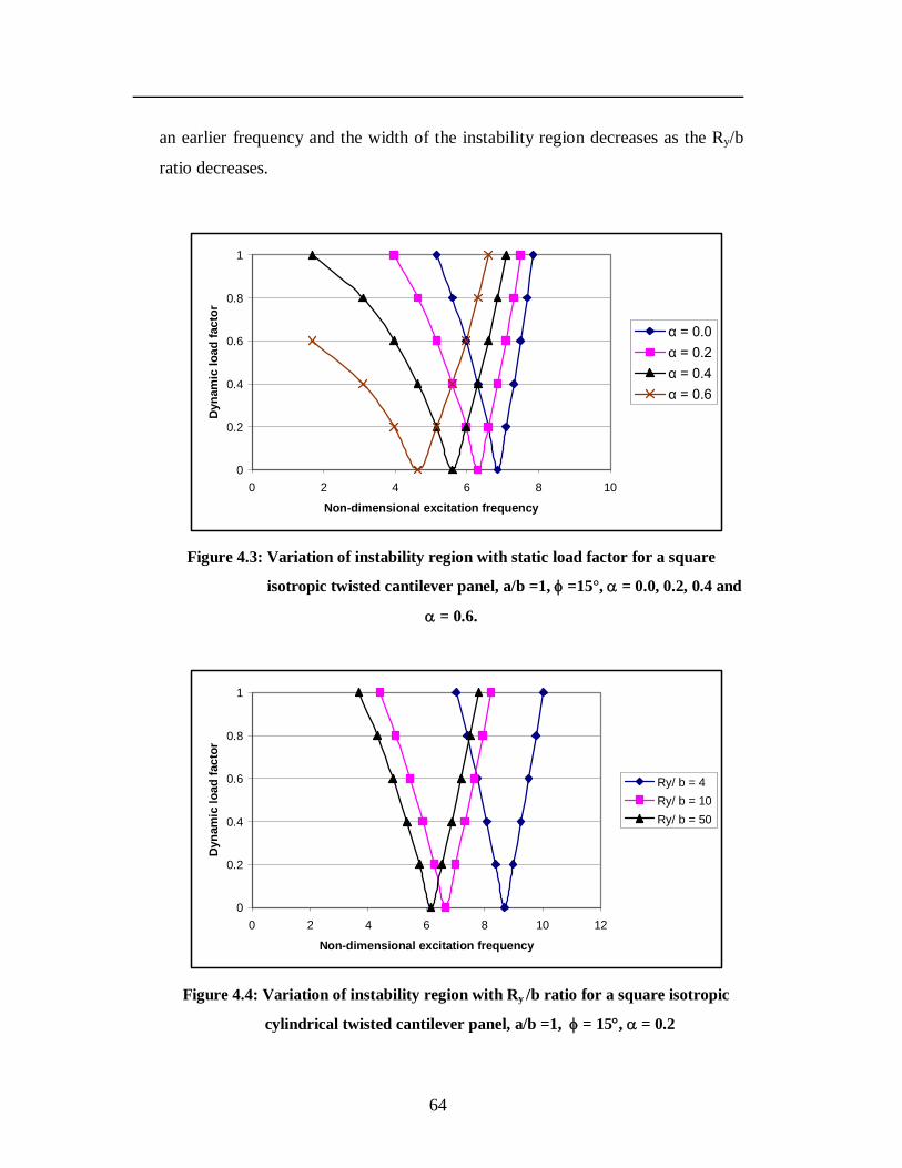
64
an earlier frequency and the width of the instability region decreases as the Ry/b
ratio decreases.
0
0.2
0.4
0.6
0.8
1
0 2 4 6 8 10
Non-dimensional excitation frequency
Dyn
amic
load
fact
or
α = 0.0α = 0.2α = 0.4α = 0.6
Figure 4.3: Variation of instability region with static load factor for a square
isotropic twisted cantilever panel, a/b =1, =15°, = 0.0, 0.2, 0.4 and
= 0.6.
0
0.2
0.4
0.6
0.8
1
0 2 4 6 8 10 12
Non-dimensional excitation frequency
Dyn
amic
load
fact
or
Ry/ b = 4Ry/ b = 10Ry/ b = 50
Figure 4.4: Variation of instability region with Ry /b ratio for a square isotropic
cylindrical twisted cantilever panel, a/b =1, = 15, = 0.2
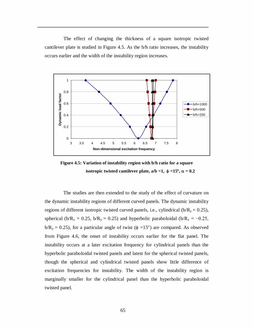
65
The effect of changing the thickness of a square isotropic twisted
cantilever plate is studied in Figure 4.5. As the b/h ratio increases, the instability
occurs earlier and the width of the instability region increases.
0
0.2
0.4
0.6
0.8
1
3 3.5 4 4.5 5 5.5 6 6.5 7 7.5 8
Non-dimensional excitation frequency
Dyn
amic
load
fact
or
b/h=1000b/h=500b/h=250
Figure 4.5: Variation of instability region with b/h ratio for a square
isotropic twisted cantilever plate, a/b =1, =15, = 0.2
The studies are then extended to the study of the effect of curvature on
the dynamic instability regions of different curved panels. The dynamic instability
regions of different isotropic twisted curved panels, i.e., cylindrical (b/Ry = 0.25),
spherical (b/Rx = 0.25, b/Ry = 0.25) and hyperbolic paraboloidal (b/Rx = −0.25,
b/Ry = 0.25), for a particular angle of twist ( =15) are compared. As observed
from Figure 4.6, the onset of instability occurs earlier for the flat panel. The
instability occurs at a later excitation frequency for cylindrical panels than the
hyperbolic paraboloidal twisted panels and latest for the spherical twisted panels,
though the spherical and cylindrical twisted panels show little difference of
excitation frequencies for instability. The width of the instability region is
marginally smaller for the cylindrical panel than the hyperbolic paraboloidal
twisted panel.
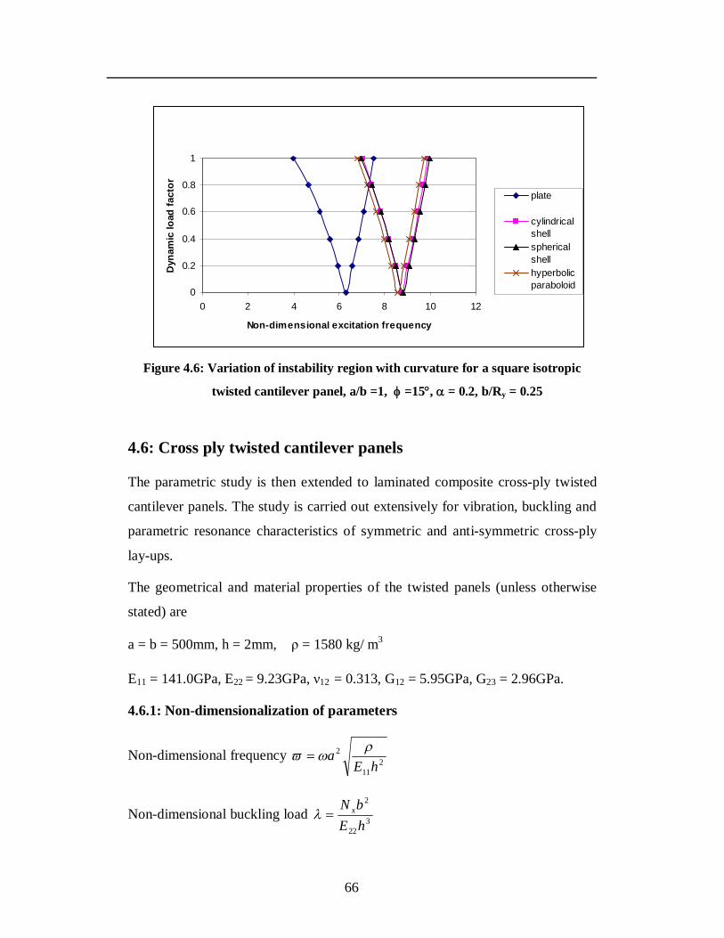
66
0
0.2
0.4
0.6
0.8
1
0 2 4 6 8 10 12
Non-dimensional excitation frequency
Dyn
amic
load
fact
or
plate
cylindrical shellsphericalshellhyperbolicparaboloid
Figure 4.6: Variation of instability region with curvature for a square isotropic
twisted cantilever panel, a/b =1, =15, = 0.2, b/Ry = 0.25
4.6: Cross ply twisted cantilever panels
The parametric study is then extended to laminated composite cross-ply twisted
cantilever panels. The study is carried out extensively for vibration, buckling and
parametric resonance characteristics of symmetric and anti-symmetric cross-ply
lay-ups.
The geometrical and material properties of the twisted panels (unless otherwise
stated) are
a = b = 500mm, h = 2mm, ρ = 1580 kg/ m3
E11 = 141.0GPa, E22 = 9.23GPa, ν12 = 0.313, G12 = 5.95GPa, G23 = 2.96GPa.
4.6.1: Non-dimensionalization of parameters
Non-dimensional frequency 211
2
hEa
Non-dimensional buckling load 322
2
hEbN x
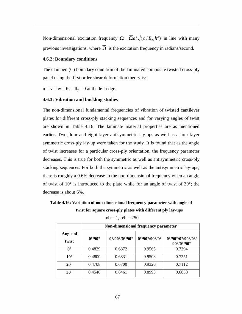
67
Non-dimensional excitation frequency )/( 222
2 hEa in line with many
previous investigations, where is the excitation frequency in radians/second.
4.6.2: Boundary conditions
The clamped (C) boundary condition of the laminated composite twisted cross-ply
panel using the first order shear deformation theory is:
u = v = w = x = y = 0 at the left edge.
4.6.3: Vibration and buckling studies
The non-dimensional fundamental frequencies of vibration of twisted cantilever
plates for different cross-ply stacking sequences and for varying angles of twist
are shown in Table 4.16. The laminate material properties are as mentioned
earlier. Two, four and eight layer antisymmetric lay-ups as well as a four layer
symmetric cross-ply lay-up were taken for the study. It is found that as the angle
of twist increases for a particular cross-ply orientation, the frequency parameter
decreases. This is true for both the symmetric as well as antisymmetric cross-ply
stacking sequences. For both the symmetric as well as the antisymmetric lay-ups,
there is roughly a 0.6% decrease in the non-dimensional frequency when an angle
of twist of 10° is introduced to the plate while for an angle of twist of 30°; the
decrease is about 6%.
Table 4.16: Variation of non-dimensional frequency parameter with angle of
twist for square cross-ply plates with different ply lay-ups
a/b = 1, b/h = 250
Angle of
twist
Non-dimensional frequency parameter
0°/90°
0°/90°/0°/90°
0°/90°/90°/0°
0°/90°/0°/90°/0°/
90°/0°/90° 0° 0.4829 0.6872 0.9565 0.7294
10° 0.4800 0.6831 0.9508 0.7251
20° 0.4708 0.6700 0.9326 0.7112
30° 0.4540 0.6461 0.8993 0.6858
68
The first five non-dimensional frequency parameters for various cross-ply twisted
cantilever plates are shown in Table 4.17. It is observed that the first frequency
parameter decreases with increase in the angle of twist for all cross-ply stacking
sequences. The second frequency parameter of twisted plate first increases and
then decreases with the increase in the angle of twist. The third frequency
parameter increases as the angle of twist increases except for the unsymmetrical
cross-ply lay-ups which first increase and then decrease with increasing twist
angle. This is also noticed for the three layer (90°/0°/90°) cross-ply. The fifth
frequency parameter increases with increasing twist angle for all ply orientations.
Table 4.18 shows the first five frequency parameters for cross-ply
cantilever twisted plates having different stacking sequences and different angles
of twist. Here E-glass/epoxy composite is used and the laminates have a square
plan form and a thickness ratio b/h = 100. As observed earlier, the first frequency
of vibration decreases with increase of angle of twist. The third and fourth
frequency parameters increase with increase in the angle of twist. However
second frequency increases and then decreases with increase of angle of twist.
The fifth frequency parameter increases with angle of twist, except for the
antisymmetric lay-ups which increase and then decrease with the increasing twist
angle. So there is some slight difference in the behaviour of the twisted plates on
changing the material of the cross-ply lamina.
Table 4.19 shows the non-dimensional fundamental frequencies for
various twisted cross-ply cylindrical and spherical shells of square plan form and
increasing R/a (radius of curvature to length ratio) ratios. The angle of twist for all
the shells is 15°. As the R/a ratio increases, the non-dimensional frequency
parameter decreases. Also for a particular cross-ply orientation and low R/a ratio,
the spherical shell shows slightly higher frequency parameter than the cylindrical
shell. For higher R/a ratios there is very little difference in the non-dimensional
frequencies of the spherical and cylindrical twisted shells for all cross-ply lay-ups.
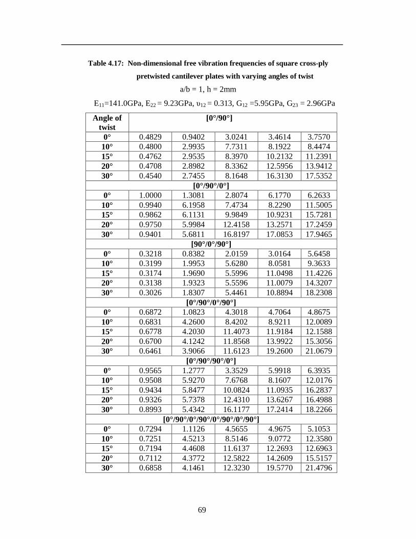
69
Table 4.17: Non-dimensional free vibration frequencies of square cross-ply
pretwisted cantilever plates with varying angles of twist
a/b = 1, h = 2mm
E11=141.0GPa, E22 = 9.23GPa, υ12 = 0.313, G12 =5.95GPa, G23 = 2.96GPa
Angle of twist
[0°/90°]
0° 0.4829 0.9402 3.0241 3.4614 3.7570 10° 0.4800 2.9935 7.7311 8.1922 8.4474 15° 0.4762 2.9535 8.3970 10.2132 11.2391 20° 0.4708 2.8982 8.3362 12.5956 13.9412 30° 0.4540 2.7455 8.1648 16.3130 17.5352
[0°/90°/0°] 0° 1.0000 1.3081 2.8074 6.1770 6.2633
10° 0.9940 6.1958 7.4734 8.2290 11.5005 15° 0.9862 6.1131 9.9849 10.9231 15.7281 20° 0.9750 5.9984 12.4158 13.2571 17.2459 30° 0.9401 5.6811 16.8197 17.0853 17.9465
[90°/0°/90°] 0° 0.3218 0.8382 2.0159 3.0164 5.6458
10° 0.3199 1.9953 5.6280 8.0581 9.3633 15° 0.3174 1.9690 5.5996 11.0498 11.4226 20° 0.3138 1.9323 5.5596 11.0079 14.3207 30° 0.3026 1.8307 5.4461 10.8894 18.2308
[0°/90°/0°/90°] 0° 0.6872 1.0823 4.3018 4.7064 4.8675
10° 0.6831 4.2600 8.4202 8.9211 12.0089 15° 0.6778 4.2030 11.4073 11.9184 12.1588 20° 0.6700 4.1242 11.8568 13.9922 15.3056 30° 0.6461 3.9066 11.6123 19.2600 21.0679
[0°/90°/90°/0°] 0° 0.9565 1.2777 3.3529 5.9918 6.3935
10° 0.9508 5.9270 7.6768 8.1607 12.0176 15° 0.9434 5.8477 10.0824 11.0935 16.2837 20° 0.9326 5.7378 12.4310 13.6267 16.4988 30° 0.8993 5.4342 16.1177 17.2414 18.2266
[0°/90°/0°/90°/0°/90°/0°/90°] 0° 0.7294 1.1126 4.5655 4.9675 5.1053
10° 0.7251 4.5213 8.5146 9.0772 12.3580 15° 0.7194 4.4608 11.6137 12.2693 12.6963 20° 0.7112 4.3772 12.5822 14.2609 15.5157 30° 0.6858 4.1461 12.3230 19.5770 21.4796
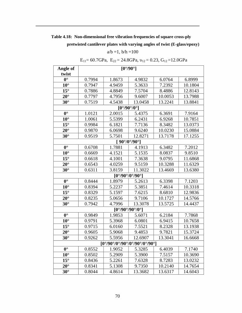
70
Table 4.18: Non-dimensional free vibration frequencies of square cross-ply
pretwisted cantilever plates with varying angles of twist (E-glass/epoxy)
a/b =1, b/h =100
E11= 60.7GPa, E22 = 24.8GPa, υ12 = 0.23, G12 =12.0GPa
Angle of twist
[0°/90°]
0° 0.7994 1.8673 4.9832 6.0764 6.8999 10° 0.7947 4.9459 5.3633 7.2392 10.1804 15° 0.7886 4.8849 7.5704 8.4886 12.8143 20° 0.7797 4.7956 9.6007 10.0053 13.7988 30° 0.7519 4.5438 13.0458 13.2241 13.8841
[0°/90°/0°] 0° 1.0121 2.0015 5.4375 6.3691 7.9164
10° 1.0061 5.5399 6.2431 6.9268 10.7851 15° 0.9984 6.1821 7.7136 8.3482 13.0373 20° 0.9870 6.0698 9.6240 10.0230 15.0884 30° 0.9519 5.7501 12.8271 13.7178 17.1255
[ 90°/0°/90°] 0° 0.6708 1.7881 4.1913 6.3482 7.2012
10° 0.6669 4.1521 5.1535 8.0837 9.8510 15° 0.6618 4.1001 7.3638 9.0795 11.6868 20° 0.6543 4.0259 9.5159 10.3288 11.6329 30° 0.6311 3.8159 11.3022 13.4669 13.6380
[0°/90°/0°/90°] 0° 0.8444 1.8979 5.2613 6.3398 7.1203
10° 0.8394 5.2237 5.3851 7.4614 10.3318 15° 0.8329 5.1597 7.6215 8.6810 12.9836 20° 0.8235 5.0656 9.7106 10.1727 14.5766 30° 0.7942 4.7996 13.3078 13.5725 14.4437
[0°/90°/90°/0°] 0° 0.9849 1.9853 5.6071 6.2184 7.7868
10° 0.9791 5.3968 6.0801 6.9415 10.7658 15° 0.9715 6.0160 7.5521 8.2328 13.1938 20° 0.9605 5.9068 9.4853 9.7821 15.3724 30° 0.9262 5.5956 12.6907 13.3041 16.6668
[0°/90°/0°/90°/0°/90°/0°/90°] 0° 0.8552 1.9052 5.3285 6.4039 7.1740
10° 0.8502 5.2909 5.3900 7.5157 10.3690 15° 0.8436 5.2261 7.6328 8.7283 13.0232 20° 0.8341 5.1308 9.7350 10.2140 14.7654 30° 0.8044 4.8614 13.3682 13.6317 14.6043
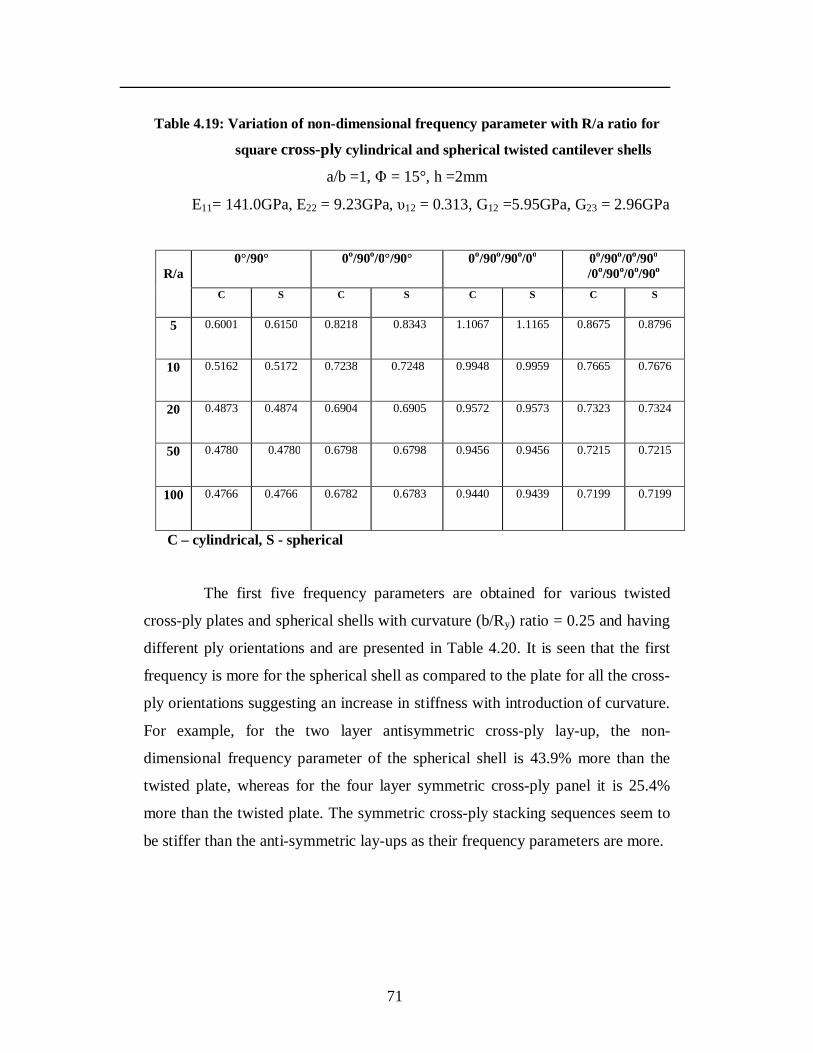
71
Table 4.19: Variation of non-dimensional frequency parameter with R/a ratio for
square cross-ply cylindrical and spherical twisted cantilever shells
a/b =1, Φ = 15°, h =2mm
E11= 141.0GPa, E22 = 9.23GPa, υ12 = 0.313, G12 =5.95GPa, G23 = 2.96GPa
R/a 0°/90° 0o/90o/0°/90° 0o/90o/90o/0o 0o/90o/0o/90o
/0o/90o/0o/90o C S C S C S C S
5 0.6001 0.6150
0.8218 0.8343 1.1067 1.1165
0.8675 0.8796
10 0.5162
0.5172
0.7238 0.7248 0.9948 0.9959 0.7665 0.7676
20 0.4873
0.4874 0.6904 0.6905 0.9572 0.9573 0.7323 0.7324
50 0.4780
0.4780 0.6798 0.6798 0.9456 0.9456 0.7215 0.7215
100 0.4766 0.4766 0.6782 0.6783 0.9440 0.9439 0.7199 0.7199
C – cylindrical, S - spherical
The first five frequency parameters are obtained for various twisted
cross-ply plates and spherical shells with curvature (b/Ry) ratio = 0.25 and having
different ply orientations and are presented in Table 4.20. It is seen that the first
frequency is more for the spherical shell as compared to the plate for all the cross-
ply orientations suggesting an increase in stiffness with introduction of curvature.
For example, for the two layer antisymmetric cross-ply lay-up, the non-
dimensional frequency parameter of the spherical shell is 43.9% more than the
twisted plate, whereas for the four layer symmetric cross-ply panel it is 25.4%
more than the twisted plate. The symmetric cross-ply stacking sequences seem to
be stiffer than the anti-symmetric lay-ups as their frequency parameters are more.
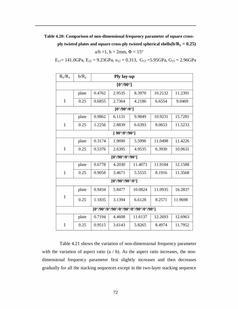
72
Table 4.20: Comparison of non-dimensional frequency parameter of square cross-
ply twisted plates and square cross-ply twisted spherical shells(b/Ry = 0.25)
a/b =1, h = 2mm, Φ = 15°
E11= 141.0GPa, E22 = 9.23GPa, υ12 = 0.313, G12 =5.95GPa, G23 = 2.96GPa
Ry/Rx b/Ry Ply lay-up
[0°/90°]
1
plate 0.4762 2.9535 8.3970 10.2132 11.2391
0.25 0.6855 2.7364 4.2186 6.6554 9.0469
[0°/90°/0°]
1
plate 0.9862 6.1131 9.9849 10.9231 15.7281
0.25 1.2256 2.8839 6.6393 8.0653 11.5233
[ 90°/0°/90°]
1
plate 0.3174 1.9690 5.5996 11.0498 11.4226
0.25 0.5376 2.6395 4.9535 6.3930 10.0631
[0°/90°/0°/90°]
1
plate 0.6778 4.2030 11.4073 11.9184 12.1588
0.25 0.9058 3.4671 5.5555 8.1916 11.3568
[0°/90°/90°/0°]
1 plate 0.9434 5.8477 10.0824 11.0935 16.2837
0.25 1.1835 3.1394 6.6128 8.2571 11.9698
[0°/90°/0°/90°/0°/90°/0°/90°/0°/90°]
1
plate 0.7194 4.4608 11.6137 12.2693 12.6963
0.25 0.9515 3.6143 5.8265 8.4974 11.7952
Table 4.21 shows the variation of non-dimensional frequency parameter
with the variation of aspect ratio (a / b). As the aspect ratio increases, the non-
dimensional frequency parameter first slightly increases and then decreases
gradually for all the stacking sequences except in the two-layer stacking sequence
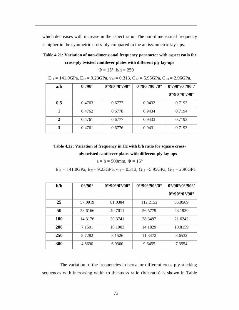
73
which decreases with increase in the aspect ratio. The non-dimensional frequency
is higher in the symmetric cross-ply compared to the antisymmetric lay-ups.
Table 4.21: Variation of non-dimensional frequency parameter with aspect ratio for
cross-ply twisted cantilever plates with different ply lay-ups
Φ = 15°, b/h = 250
E11 = 141.0GPa, E22 = 9.23GPa, ν12 = 0.313, G12 = 5.95GPa, G23 = 2.96GPa.
a/b 0°/90° 0°/90°/0°/90° 0°/90°/90°/0° 0°/90°/0°/90°/
0°/90°/0°/90°
0.5 0.4763 0.6777 0.9432 0.7193
1 0.4762 0.6778 0.9434 0.7194
2 0.4761 0.6777 0.9433 0.7193
3 0.4761 0.6776 0.9431 0.7193
Table 4.22: Variation of frequency in Hz with b/h ratio for square cross-
ply twisted cantilever plates with different ply lay-ups
a = b = 500mm, Φ = 15°
E11 = 141.0GPa, E22= 9.23GPa, ν12 = 0.313, G12 =5.95GPa, G23 = 2.96GPa.
b/h 0°/90° 0°/90°/0°/90° 0°/90°/90°/0° 0°/90°/0°/90°/
0°/90°/0°/90°
25 57.0919 81.0384 112.2152 85.9569
50 28.6166 40.7011 56.5779 43.1930
100 14.3176 20.3741 28.3497 21.6242
200 7.1601 10.1903 14.1829 10.8159
250 5.7282 8.1526 11.3472 8.6532
300 4.8690 6.9300 9.6455 7.3554
The variation of the frequencies in hertz for different cross-ply stacking
sequences with increasing width to thickness ratio (b/h ratio) is shown in Table

74
4.22. It is seen that as the thickness of the plate decreases the frequency in hertz is
decreasing due to decrease of stiffness. This is seen to be true for both symmetric
and antisymmetric cross-ply stacking sequences.
The effect of curvature on the non-dimensional frequency parameter is
next studied. The width to radius of curvature ratio (b/Ry) is taken as 0.25.
Cylindrical, spherical and hyperbolic paraboloid twisted shells are analyzed and
results compared with those of the twisted plate for various cross-ply stacking
sequences. The angle of twist in all cases is taken as 15°. The results are tabulated
in Table 4.23. The introduction of curvature increases the non-dimensional
frequency parameter as compared with that of the twisted plate. This suggests an
increase in the stiffness with introduction of curvature. Spherical twisted shells
show the highest frequency parameters for a particular stacking sequence. For
example, for the two layer antisymmetric ply lay-up, the non-dimensional
frequency is 44% more than the twisted plate, followed by the cylindrical twisted
panels (36.7% more than the twisted plate) and hyperbolic paraboloidal twisted
panels (30.9% more than the twisted plate).
Table 4.23: Variation of non-dimensional frequency parameter with geometry for
cross-ply twisted cantilever plates with different ply lay-ups
a/ b = 1, h = 2 mm, b/Ry = 0.25
E11= 141.0GPa, E22 = 9.23GPa, υ12= 0.313, G12 = 5.95GPa, G23 = 2.96GPa
No.of Layers
Plate Cylindrical
shell
Spherical
shell
Hyperbolic
Paraboloid
shell
0°/90° 0.4762 0.6510 0.6856 0.6234
0°/90°/90°/0° 0.9434 1.1688 1.1835 1.1406
0°/90°/0°/90° 0.6778 0.8791 0.9058 0.8507
0°/90°/0°/90°/0°/
90°/0°/90° 0.7194 0.9262 0.9515 0.8976
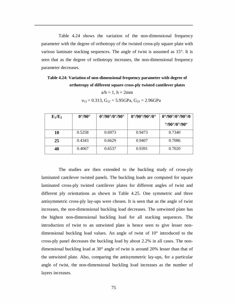
75
Table 4.24 shows the variation of the non-dimensional frequency
parameter with the degree of orthotropy of the twisted cross-ply square plate with
various laminate stacking sequences. The angle of twist is assumed as 15°. It is
seen that as the degree of orthotropy increases, the non-dimensional frequency
parameter decreases.
Table 4.24: Variation of non-dimensional frequency parameter with degree of
orthotropy of different square cross-ply twisted cantilever plates a/b = 1, h = 2mm
υ12 = 0.313, G12 = 5.95GPa, G23 = 2.96GPa
E1/E2 0°/90° 0°/90°/0°/90° 0°/90°/90°/0° 0°/90°/0°/90°/0
°/90°/0°/90°
10 0.5258 0.6973 0.9473 0.7340
25 0.4343 0.6629 0.9407 0.7086
40 0.4067 0.6537 0.9391 0.7020
The studies are then extended to the buckling study of cross-ply
laminated cantilever twisted panels. The buckling loads are computed for square
laminated cross-ply twisted cantilever plates for different angles of twist and
different ply orientations as shown in Table 4.25. One symmetric and three
antisymmetric cross-ply lay-ups were chosen. It is seen that as the angle of twist
increases, the non-dimensional buckling load decreases. The untwisted plate has
the highest non-dimensional buckling load for all stacking sequences. The
introduction of twist to an untwisted plate is hence seen to give lesser non-
dimensional buckling load values. An angle of twist of 10° introduced to the
cross-ply panel decreases the buckling load by about 2.2% in all cases. The non-
dimensional buckling load at 30° angle of twist is around 20% lesser than that of
the untwisted plate. Also, comparing the antisymmetric lay-ups, for a particular
angle of twist, the non-dimensional buckling load increases as the number of
layers increases.
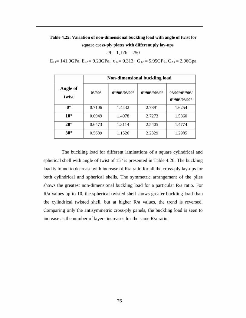
76
Table 4.25: Variation of non-dimensional buckling load with angle of twist for
square cross-ply plates with different ply lay-ups
a/b =1, b/h = 250
E11= 141.0GPa, E22 = 9.23GPa, υ12= 0.313, G12 = 5.95GPa, G23 = 2.96Gpa
Angle of
twist
Non-dimensional buckling load
0°/90°
0°/90°/0°/90°
0°/90°/90°/0°
0°/90°/0°/90°/
0°/90°/0°/90°
0° 0.7106 1.4432 2.7891 1.6254
10° 0.6949 1.4078 2.7273 1.5860
20° 0.6473 1.3114 2.5405 1.4774
30° 0.5689 1.1526 2.2329 1.2985
The buckling load for different laminations of a square cylindrical and
spherical shell with angle of twist of 15° is presented in Table 4.26. The buckling
load is found to decrease with increase of R/a ratio for all the cross-ply lay-ups for
both cylindrical and spherical shells. The symmetric arrangement of the plies
shows the greatest non-dimensional buckling load for a particular R/a ratio. For
R/a values up to 10, the spherical twisted shell shows greater buckling load than
the cylindrical twisted shell, but at higher R/a values, the trend is reversed.
Comparing only the antisymmetric cross-ply panels, the buckling load is seen to
increase as the number of layers increases for the same R/a ratio.
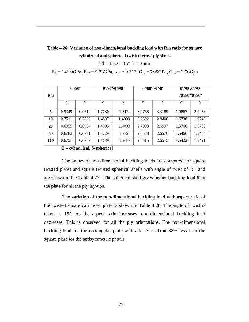
77
Table 4.26: Variation of non-dimensional buckling load with R/a ratio for square
cylindrical and spherical twisted cross-ply shells
a/b =1, Φ = 15°, h = 2mm
E11= 141.0GPa, E22 = 9.23GPa, υ12 = 0.313, G12 =5.95GPa, G23 = 2.96Gpa
R/a
0°/90° 0o/90o/0°/90° 0o/90o/90o/0o 0o/90o/0o/90o
/0o/90o/0o/90o C S C S C S C S
5 0.9349 0.9710 1.7780 1.8170 3.2768 3.3189 1.9867 2.0258
10 0.7511 0.7523 1.4897 1.4909 2.8392 2.8400 1.6736 1.6748
20 0.6955 0.6954 1.4005 1.4003 2.7003 2.6997 1.5766 1.5763
50 0.6782 0.6781 1.3729 1.3728 2.6578 2.6576 1.5466 1.5465
100 0.6757 0.6757 1.3689 1.3689 2.6515 2.6515 1.5422 1.5421
C – cylindrical, S-spherical
The values of non-dimensional buckling loads are compared for square
twisted plates and square twisted spherical shells with angle of twist of 15° and
are shown in the Table 4.27. The spherical shell gives higher buckling load than
the plate for all the ply lay-ups.
The variation of the non-dimensional buckling load with aspect ratio of
the twisted square cantilever plate is shown in Table 4.28. The angle of twist is
taken as 15°. As the aspect ratio increases, non-dimensional buckling load
decreases. This is observed for all the ply orientations. The non-dimensional
buckling load for the rectangular plate with a/b =3 is about 88% less than the
square plate for the antisymmetric panels.
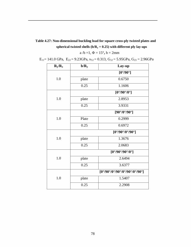
78
Table 4.27: Non-dimensional buckling load for square cross-ply twisted plates and
spherical twisted shells (b/Ry = 0.25) with different ply lay-ups
a /b =1, Φ = 15°, h = 2mm
E11= 141.0 GPa, E22 = 9.23GPa, υ12 = 0.313, G12 = 5.95GPa, G23 = 2.96GPa
Ry/Rx b/Ry Lay-up
1.0
[0°/90°]
plate 0.6750
0.25 1.1606
1.0
[0°/90°/0°]
plate 2.8953
0.25 3.9331
1.0
[90°/0°/90°]
Plate 0.2999
0.25 0.6972
1.0
[0°/90°/0°/90°]
plate 1.3676
0.25 2.0683
1.0
[0°/90°/90°/0°]
plate 2.6494
0.25 3.6377
1.0
[0°/90°/0°/90°/0°/90°/0°/90°]
plate 1.5407
0.25 2.2908

79
Table 4.28: Variation of non-dimensional buckling load with aspect ratio for cross-
ply twisted cantilever plates with different ply lay-ups
b/h = 250, Φ = 15°
E11 = 141.0GPa, E22= 9.23GPa, ν12 = 0.313, G12 =5.95GPa, G23 = 2.96GPa.
a/b 0°/90° 0°/90°/0°/90° 0°/90°/90°/0° 0°/90°/0°/90°/
0°/90°/0°/90°
0.5 2.7010 5.4706 10.5967 6.1628
1 0.6750 1.3676 2.6494 1.5407
2 0.1687 0.3418 0.6621 0.3851
3 0.0750 0.1519 0.2941 0.1711
Table 4.29 shows the variation of buckling load with b / h ratio. The
angle of twist is taken as 15°. As the thickness of the twisted plate decreases, the
buckling load decreases for all the ply orientations.
Next, the variation of non-dimensional buckling load for different shell
geometries is studied and is shown in Table 4.30. The b /Ry ratio is taken as 0.25
and angle of twist as 15°. It is observed that introduction of curvature in the plate
increases the non-dimensional buckling load. For a particular stacking sequence,
the spherical twisted panel shows the highest non-dimensional buckling load
while the plate shows the least non-dimensional buckling load. This is observed
for both the symmetric as well as antisymmetric lay-ups. For the two layer lay-up,
the non-dimensional buckling load of the cylindrical twisted panel is 57.9%
greater than that of the twisted plate, while the spherical twisted panel is 71.9%
more and the hyperbolic paraboloidal twisted panel is 42.1% more than that of the
twisted plate. Also for antisymmetric stacking sequences, the buckling load
increases with increase in the number of layers.
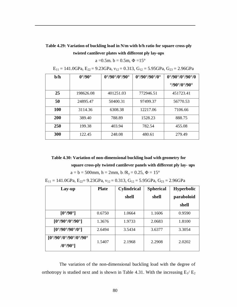
80
Table 4.29: Variation of buckling load in N/m with b/h ratio for square cross-ply
twisted cantilever plates with different ply lay-ups
a =0.5m. b = 0.5m, Φ =15°
E11 = 141.0GPa, E22 = 9.23GPa, ν12 = 0.313, G12 = 5.95GPa, G23 = 2.96GPa
b/h 0°/90° 0°/90°/0°/90° 0°/90°/90°/0° 0°/90°/0°/90°/0
°/90°/0°/90°
25 198626.08 401251.03 772946.51 451723.41
50 24895.47 50400.31 97499.37 56770.53
100 3114.36 6308.38 12217.06 7106.66
200 389.40 788.89 1528.23 888.75
250 199.38 403.94 782.54 455.08
300 122.45 248.08 480.61 279.49
Table 4.30: Variation of non-dimensional buckling load with geometry for
square cross-ply twisted cantilever panels with different ply lay- ups
a = b = 500mm, h = 2mm, b /Ry = 0.25, Φ = 15°
E11 = 141.0GPa, E22= 9.23GPa, ν12 = 0.313, G12 = 5.95GPa, G23 = 2.96GPa
Lay-up Plate Cylindrical
shell
Spherical
shell
Hyperbolic
paraboloid
shell
[0°/90°] 0.6750 1.0664 1.1606 0.9590
[0°/90°/0°/90°] 1.3676 1.9733 2.0683 1.8100
[0°/90°/90°/0°] 2.6494 3.5434 3.6377 3.3054
[0°/90°/0°/90°/0°/90°
/0°/90°] 1.5407 2.1968 2.2908 2.0202
The variation of the non-dimensional buckling load with the degree of
orthotropy is studied next and is shown in Table 4.31. With the increasing E1/ E2
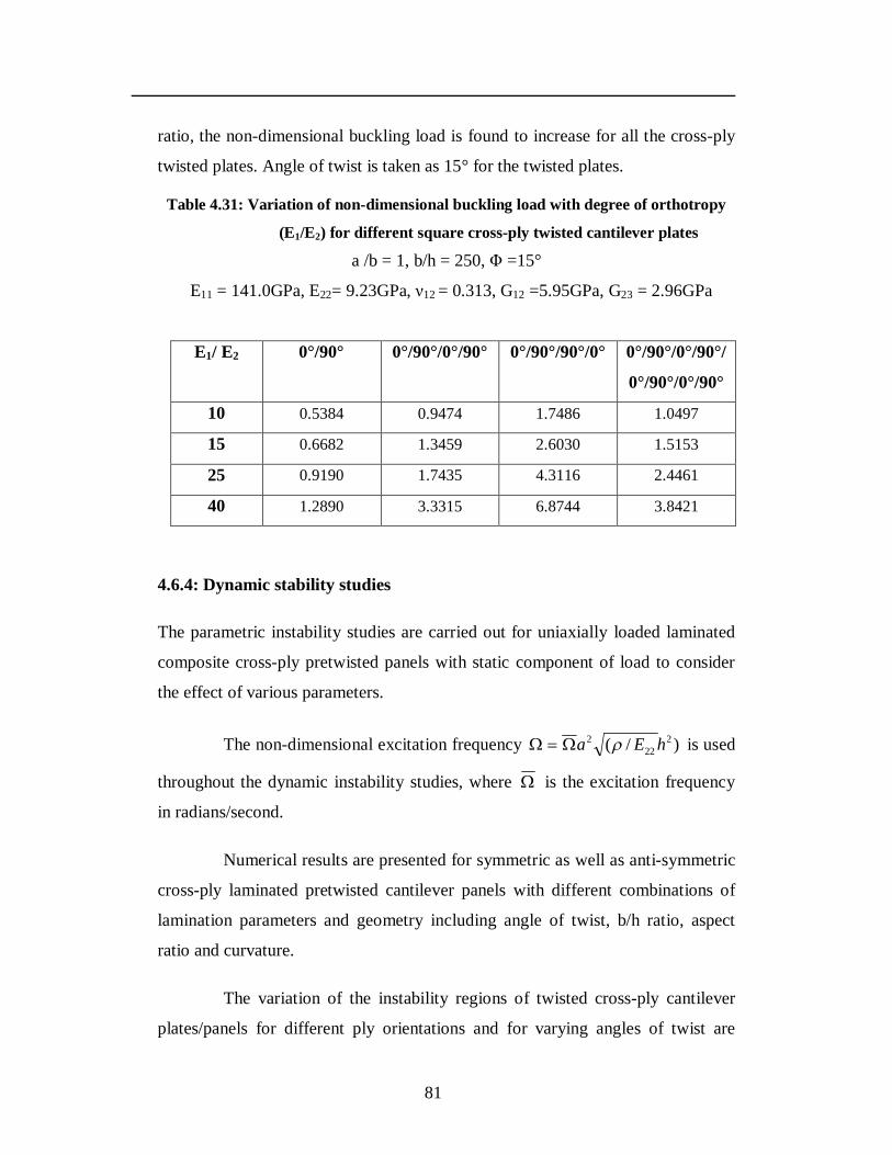
81
ratio, the non-dimensional buckling load is found to increase for all the cross-ply
twisted plates. Angle of twist is taken as 15° for the twisted plates.
Table 4.31: Variation of non-dimensional buckling load with degree of orthotropy
(E1/E2) for different square cross-ply twisted cantilever plates
a /b = 1, b/h = 250, Φ =15°
E11 = 141.0GPa, E22= 9.23GPa, ν12 = 0.313, G12 =5.95GPa, G23 = 2.96GPa
E1/ E2 0°/90° 0°/90°/0°/90° 0°/90°/90°/0° 0°/90°/0°/90°/
0°/90°/0°/90°
10 0.5384 0.9474 1.7486 1.0497
15 0.6682 1.3459 2.6030 1.5153
25 0.9190 1.7435 4.3116 2.4461
40 1.2890 3.3315 6.8744 3.8421
4.6.4: Dynamic stability studies
The parametric instability studies are carried out for uniaxially loaded laminated
composite cross-ply pretwisted panels with static component of load to consider
the effect of various parameters.
The non-dimensional excitation frequency )/( 222
2 hEa is used
throughout the dynamic instability studies, where is the excitation frequency
in radians/second.
Numerical results are presented for symmetric as well as anti-symmetric
cross-ply laminated pretwisted cantilever panels with different combinations of
lamination parameters and geometry including angle of twist, b/h ratio, aspect
ratio and curvature.
The variation of the instability regions of twisted cross-ply cantilever
plates/panels for different ply orientations and for varying angles of twist are
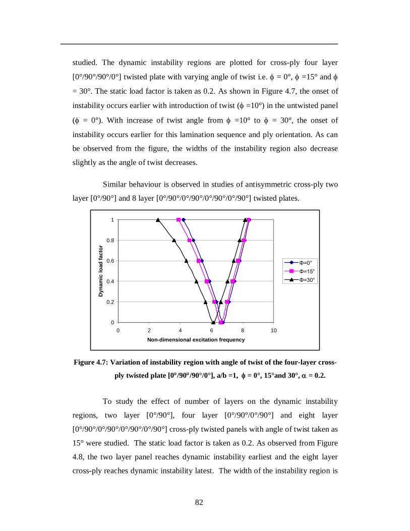
82
studied. The dynamic instability regions are plotted for cross-ply four layer
[0°/90°/90°/0°] twisted plate with varying angle of twist i.e. = 0°, =15° and
= 30°. The static load factor is taken as 0.2. As shown in Figure 4.7, the onset of
instability occurs earlier with introduction of twist ( =10°) in the untwisted panel
( = 0°). With increase of twist angle from =10° to = 30°, the onset of
instability occurs earlier for this lamination sequence and ply orientation. As can
be observed from the figure, the widths of the instability region also decrease
slightly as the angle of twist decreases.
Similar behaviour is observed in studies of antisymmetric cross-ply two
layer [0°/90°] and 8 layer [0°/90°/0°/90°/0°/90°/0°/90°] twisted plates.
0
0.2
0.4
0.6
0.8
1
0 2 4 6 8 10
Non-dimensional excitation frequency
Dyn
amic
load
fact
or
Φ=0°Φ=15°Φ=30°
Figure 4.7: Variation of instability region with angle of twist of the four-layer cross-
ply twisted plate [0/90/90°/0°], a/b =1, = 0°, 15°and 30°, = 0.2.
To study the effect of number of layers on the dynamic instability
regions, two layer [0°/90°], four layer [0°/90°/0°/90°] and eight layer
[0°/90°/0°/90°/0°/90°/0°/90°] cross-ply twisted panels with angle of twist taken as
15° were studied. The static load factor is taken as 0.2. As observed from Figure
4.8, the two layer panel reaches dynamic instability earliest and the eight layer
cross-ply reaches dynamic instability latest. The width of the instability region is
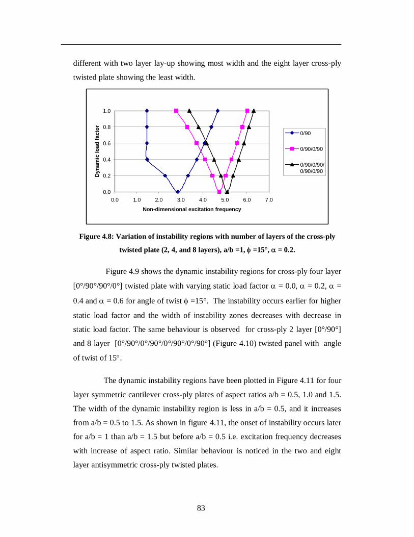
83
different with two layer lay-up showing most width and the eight layer cross-ply
twisted plate showing the least width.
0.0
0.2
0.4
0.6
0.8
1.0
0.0 1.0 2.0 3.0 4.0 5.0 6.0 7.0
Non-dimensional excitation frequency
Dyn
amic
load
fact
or
0/90
0/90/0/90
0/90/0/90/0/90/0/90
Figure 4.8: Variation of instability regions with number of layers of the cross-ply
twisted plate (2, 4, and 8 layers), a/b =1, =15°, = 0.2.
Figure 4.9 shows the dynamic instability regions for cross-ply four layer
[0°/90°/90°/0°] twisted plate with varying static load factor = 0.0, = 0.2, =
0.4 and = 0.6 for angle of twist =15°. The instability occurs earlier for higher
static load factor and the width of instability zones decreases with decrease in
static load factor. The same behaviour is observed for cross-ply 2 layer [0°/90°]
and 8 layer [0°/90°/0°/90°/0°/90°/0°/90°] (Figure 4.10) twisted panel with angle
of twist of 15.
The dynamic instability regions have been plotted in Figure 4.11 for four
layer symmetric cantilever cross-ply plates of aspect ratios a/b = 0.5, 1.0 and 1.5.
The width of the dynamic instability region is less in a/b = 0.5, and it increases
from a/b = 0.5 to 1.5. As shown in figure 4.11, the onset of instability occurs later
for a/b = 1 than a/b = 1.5 but before a/b = 0.5 i.e. excitation frequency decreases
with increase of aspect ratio. Similar behaviour is noticed in the two and eight
layer antisymmetric cross-ply twisted plates.
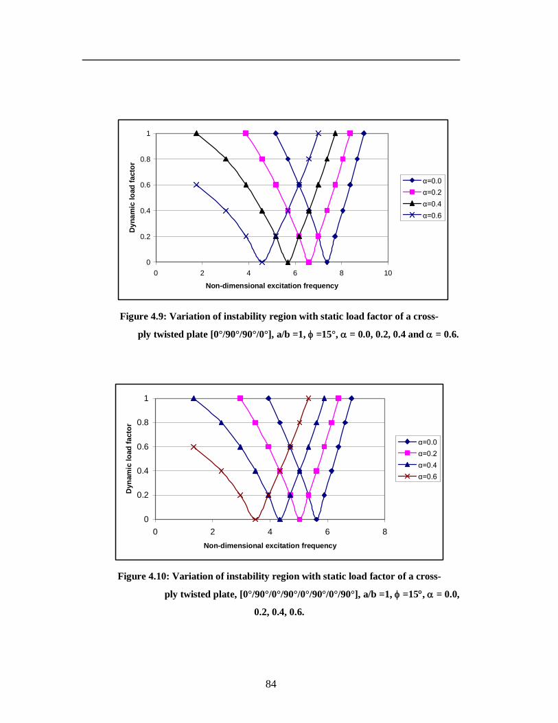
84
0
0.2
0.4
0.6
0.8
1
0 2 4 6 8 10
Non-dimensional excitation frequency
Dyn
amic
load
fact
or
α=0.0α=0.2α=0.4α=0.6
Figure 4.9: Variation of instability region with static load factor of a cross-
ply twisted plate [0°/90°/90°/0°], a/b =1, =15°, = 0.0, 0.2, 0.4 and = 0.6.
0
0.2
0.4
0.6
0.8
1
0 2 4 6 8Non-dimensional excitation frequency
Dyn
amic
load
fact
or
α=0.0α=0.2α=0.4α=0.6
Figure 4.10: Variation of instability region with static load factor of a cross-
ply twisted plate, [0°/90°/0°/90°/0°/90°/0°/90°], a/b =1, =15, = 0.0,
0.2, 0.4, 0.6.
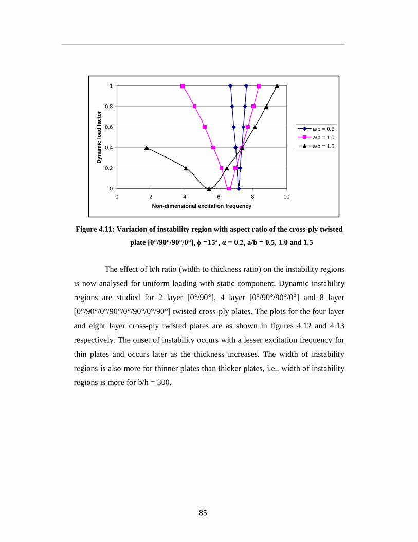
85
0
0.2
0.4
0.6
0.8
1
0 2 4 6 8 10
Non-dimensional excitation frequency
Dyn
amic
load
fact
or
a/b = 0.5a/b = 1.0a/b = 1.5
Figure 4.11: Variation of instability region with aspect ratio of the cross-ply twisted
plate [0°/90°/90°/0°], =15, α = 0.2, a/b = 0.5, 1.0 and 1.5
The effect of b/h ratio (width to thickness ratio) on the instability regions
is now analysed for uniform loading with static component. Dynamic instability
regions are studied for 2 layer [0°/90°], 4 layer [0°/90°/90°/0°] and 8 layer
[0°/90°/0°/90°/0°/90°/0°/90°] twisted cross-ply plates. The plots for the four layer
and eight layer cross-ply twisted plates are as shown in figures 4.12 and 4.13
respectively. The onset of instability occurs with a lesser excitation frequency for
thin plates and occurs later as the thickness increases. The width of instability
regions is also more for thinner plates than thicker plates, i.e., width of instability
regions is more for b/h = 300.
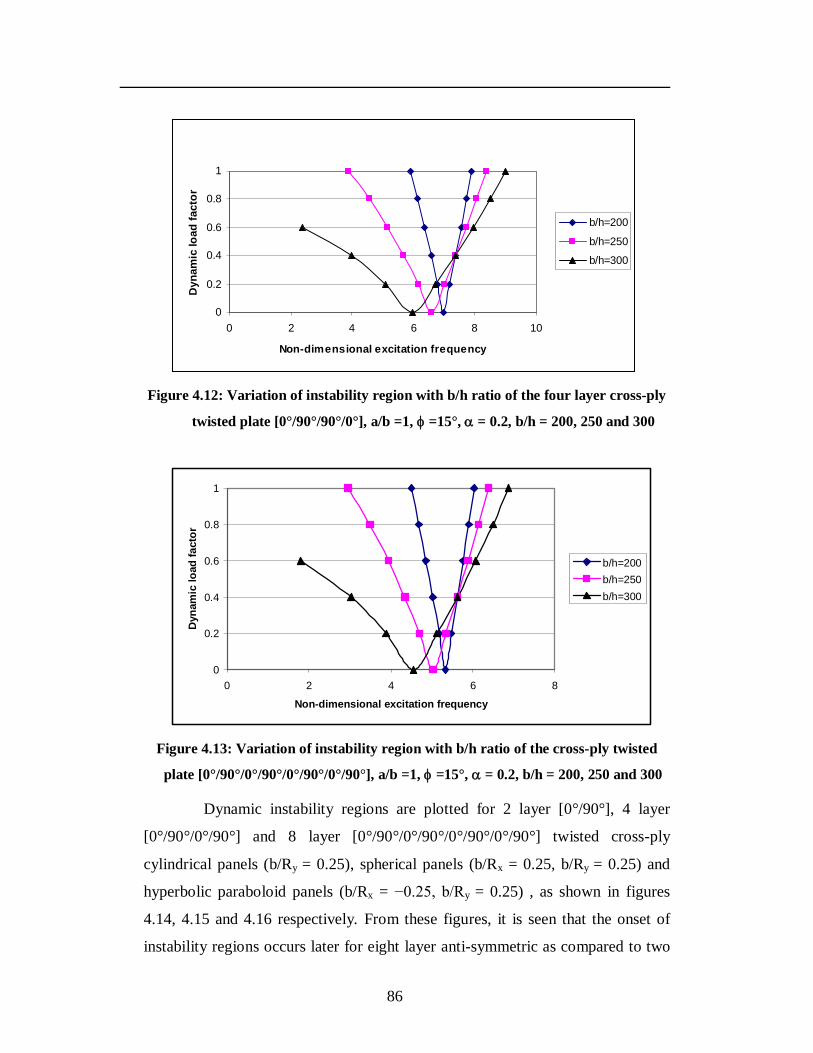
86
0
0.2
0.4
0.6
0.8
1
0 2 4 6 8 10
Non-dimensional excitation frequency
Dyn
amic
load
fact
or
b/h=200
b/h=250
b/h=300
Figure 4.12: Variation of instability region with b/h ratio of the four layer cross-ply
twisted plate [0°/90°/90°/0°], a/b =1, =15°, = 0.2, b/h = 200, 250 and 300
0
0.2
0.4
0.6
0.8
1
0 2 4 6 8
Non-dimensional excitation frequency
Dyn
amic
load
fact
or
b/h=200b/h=250b/h=300
Figure 4.13: Variation of instability region with b/h ratio of the cross-ply twisted
plate [0°/90°/0°/90°/0°/90°/0°/90°], a/b =1, =15°, = 0.2, b/h = 200, 250 and 300
Dynamic instability regions are plotted for 2 layer [0°/90°], 4 layer
[0°/90°/0°/90°] and 8 layer [0°/90°/0°/90°/0°/90°/0°/90°] twisted cross-ply
cylindrical panels (b/Ry = 0.25), spherical panels (b/Rx = 0.25, b/Ry = 0.25) and
hyperbolic paraboloid panels (b/Rx = −0.25, b/Ry = 0.25) , as shown in figures
4.14, 4.15 and 4.16 respectively. From these figures, it is seen that the onset of
instability regions occurs later for eight layer anti-symmetric as compared to two
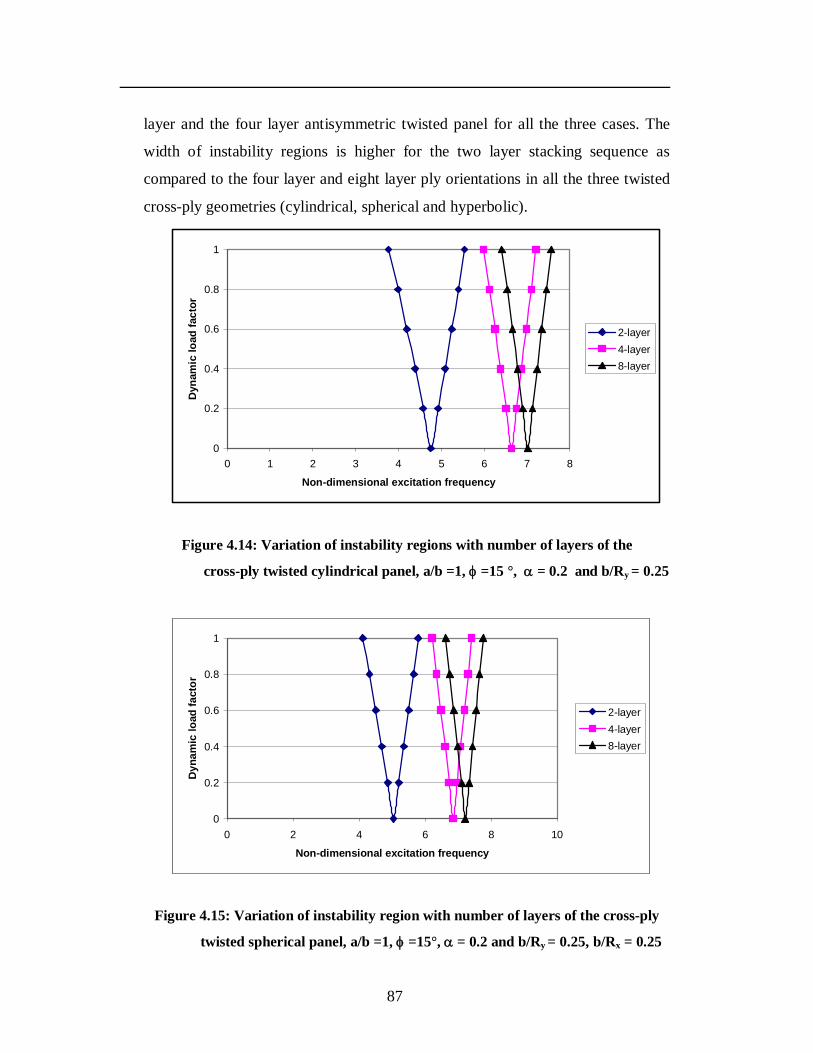
87
layer and the four layer antisymmetric twisted panel for all the three cases. The
width of instability regions is higher for the two layer stacking sequence as
compared to the four layer and eight layer ply orientations in all the three twisted
cross-ply geometries (cylindrical, spherical and hyperbolic).
0
0.2
0.4
0.6
0.8
1
0 1 2 3 4 5 6 7 8
Non-dimensional excitation frequency
Dyn
amic
load
fact
or
2-layer4-layer8-layer
Figure 4.14: Variation of instability regions with number of layers of the
cross-ply twisted cylindrical panel, a/b =1, =15 °, = 0.2 and b/Ry = 0.25
0
0.2
0.4
0.6
0.8
1
0 2 4 6 8 10
Non-dimensional excitation frequency
Dyn
amic
load
fact
or
2-layer4-layer8-layer
Figure 4.15: Variation of instability region with number of layers of the cross-ply
twisted spherical panel, a/b =1, =15°, = 0.2 and b/Ry = 0.25, b/Rx = 0.25
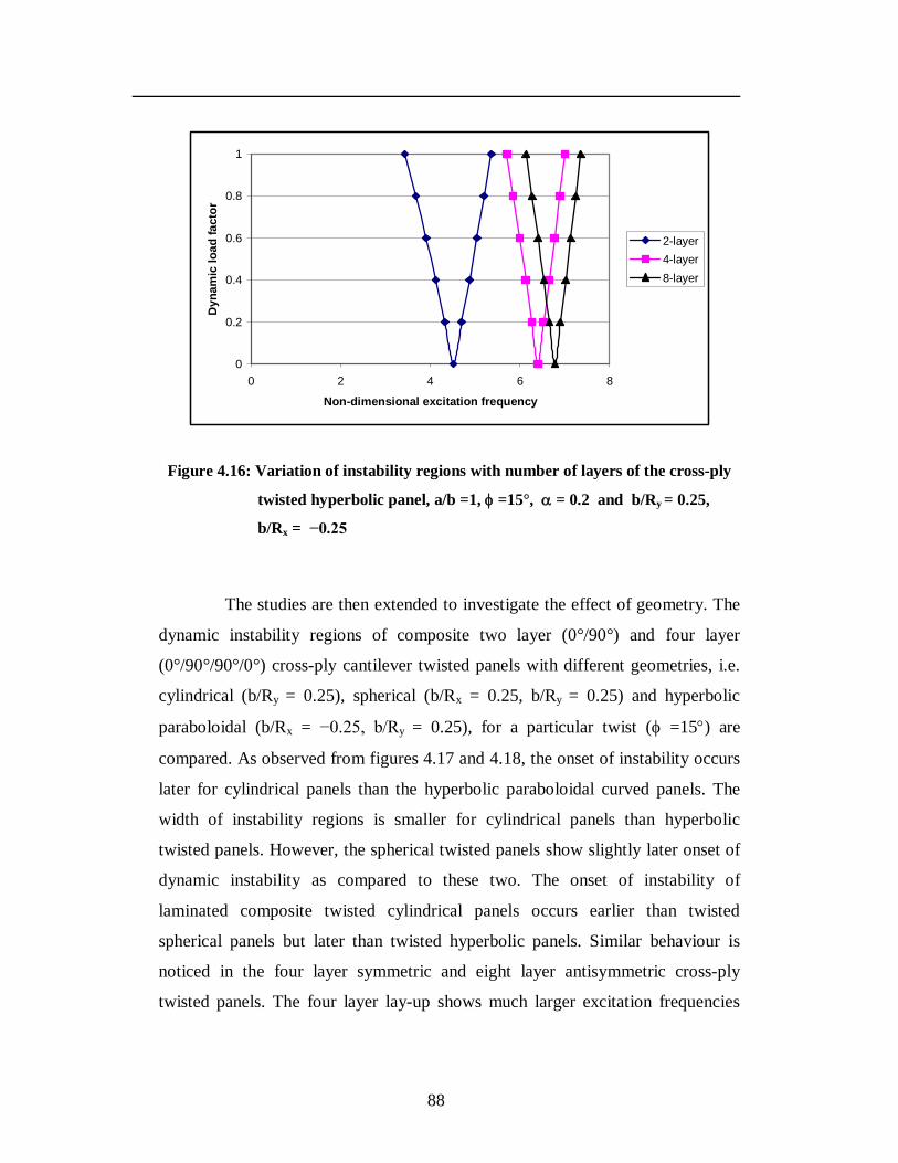
88
0
0.2
0.4
0.6
0.8
1
0 2 4 6 8
Non-dimensional excitation frequency
Dyn
amic
load
fact
or
2-layer4-layer8-layer
Figure 4.16: Variation of instability regions with number of layers of the cross-ply
twisted hyperbolic panel, a/b =1, =15°, = 0.2 and b/Ry = 0.25,
b/Rx = −0.25
The studies are then extended to investigate the effect of geometry. The
dynamic instability regions of composite two layer (0°/90°) and four layer
(0°/90°/90°/0°) cross-ply cantilever twisted panels with different geometries, i.e.
cylindrical (b/Ry = 0.25), spherical (b/Rx = 0.25, b/Ry = 0.25) and hyperbolic
paraboloidal (b/Rx = −0.25, b/Ry = 0.25), for a particular twist ( =15) are
compared. As observed from figures 4.17 and 4.18, the onset of instability occurs
later for cylindrical panels than the hyperbolic paraboloidal curved panels. The
width of instability regions is smaller for cylindrical panels than hyperbolic
twisted panels. However, the spherical twisted panels show slightly later onset of
dynamic instability as compared to these two. The onset of instability of
laminated composite twisted cylindrical panels occurs earlier than twisted
spherical panels but later than twisted hyperbolic panels. Similar behaviour is
noticed in the four layer symmetric and eight layer antisymmetric cross-ply
twisted panels. The four layer lay-up shows much larger excitation frequencies
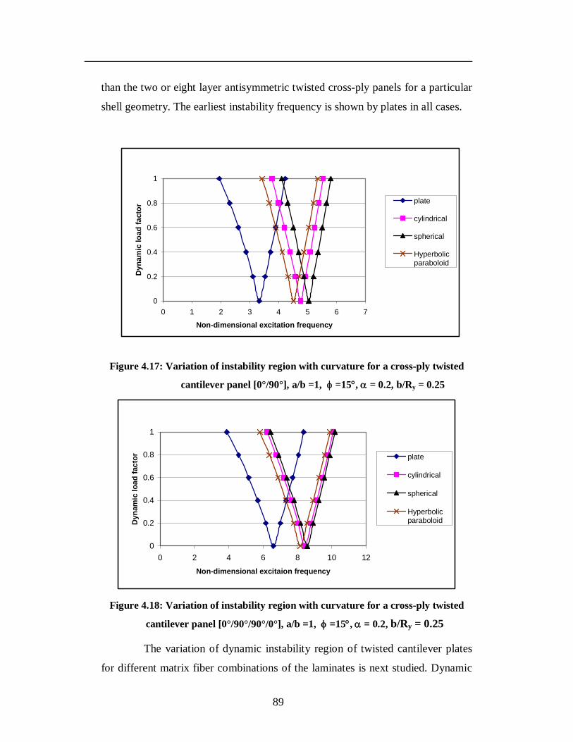
89
than the two or eight layer antisymmetric twisted cross-ply panels for a particular
shell geometry. The earliest instability frequency is shown by plates in all cases.
0
0.2
0.4
0.6
0.8
1
0 1 2 3 4 5 6 7
Non-dimensional excitation frequency
Dyn
amic
load
fact
or
plate
cylindrical
spherical
Hyperbolicparaboloid
Figure 4.17: Variation of instability region with curvature for a cross-ply twisted
cantilever panel [0°/90°], a/b =1, =15, = 0.2, b/Ry = 0.25
0
0.2
0.4
0.6
0.8
1
0 2 4 6 8 10 12
Non-dimensional excitaion frequency
Dyn
amic
load
fact
or plate
cylindrical
spherical
Hyperbolicparaboloid
Figure 4.18: Variation of instability region with curvature for a cross-ply twisted
cantilever panel [0°/90°/90°/0°], a/b =1, =15, = 0.2, b/Ry = 0.25
The variation of dynamic instability region of twisted cantilever plates
for different matrix fiber combinations of the laminates is next studied. Dynamic
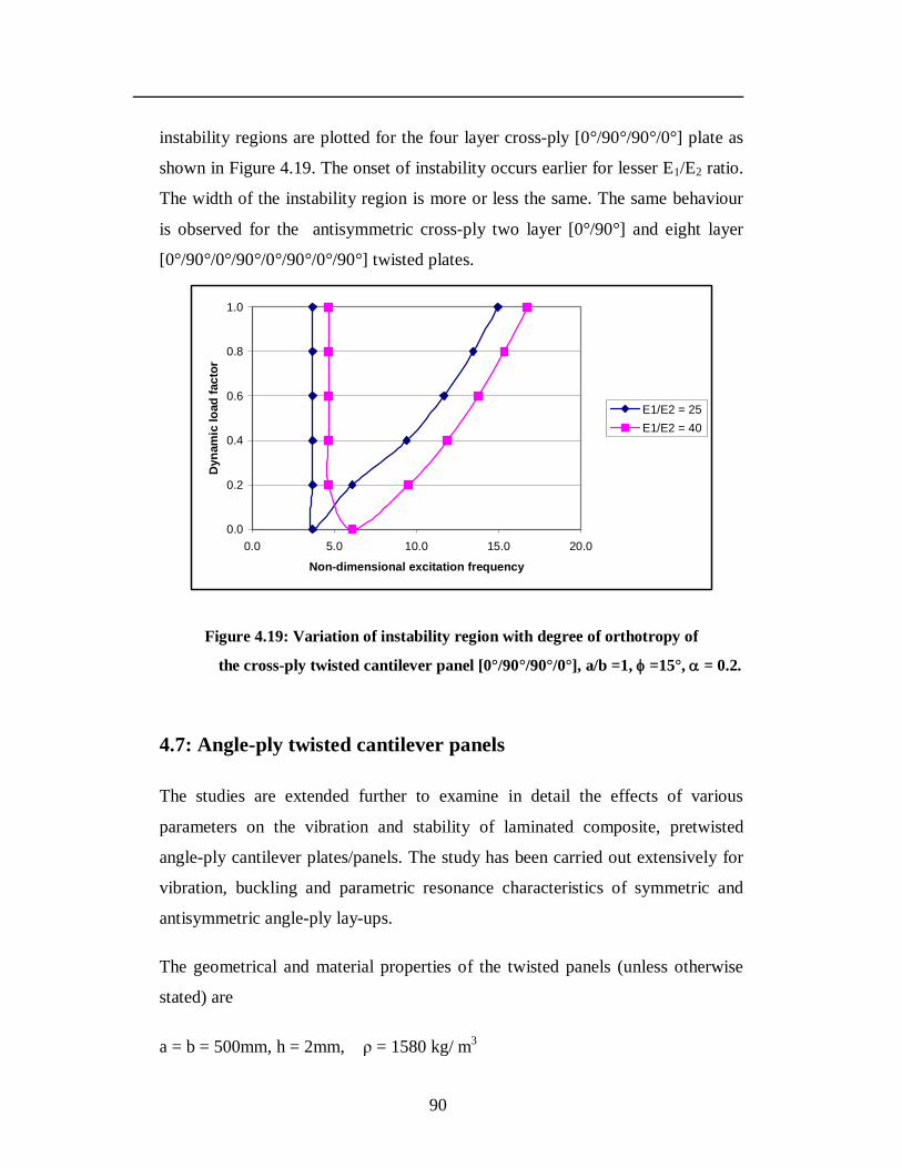
90
instability regions are plotted for the four layer cross-ply [0°/90°/90°/0°] plate as
shown in Figure 4.19. The onset of instability occurs earlier for lesser E1/E2 ratio.
The width of the instability region is more or less the same. The same behaviour
is observed for the antisymmetric cross-ply two layer [0°/90°] and eight layer
[0°/90°/0°/90°/0°/90°/0°/90°] twisted plates.
0.0
0.2
0.4
0.6
0.8
1.0
0.0 5.0 10.0 15.0 20.0
Non-dimensional excitation frequency
Dyn
amic
load
fact
or
E1/E2 = 25E1/E2 = 40
Figure 4.19: Variation of instability region with degree of orthotropy of
the cross-ply twisted cantilever panel [0°/90°/90°/0°], a/b =1, =15°, = 0.2.
4.7: Angle-ply twisted cantilever panels
The studies are extended further to examine in detail the effects of various
parameters on the vibration and stability of laminated composite, pretwisted
angle-ply cantilever plates/panels. The study has been carried out extensively for
vibration, buckling and parametric resonance characteristics of symmetric and
antisymmetric angle-ply lay-ups.
The geometrical and material properties of the twisted panels (unless otherwise
stated) are
a = b = 500mm, h = 2mm, ρ = 1580 kg/ m3
91
E11 = 141.0GPa, E22 = 9.23GPa, ν12 = 0.313, G12 = 5.95GPa, G23 = 2.96GPa.
4.7.1: Non-dimensionalization of parameters
Non-dimensional frequency 211
2
hEa
Non-dimensional buckling load 322
2
hEbN x
The non-dimensional excitation frequency )/( 222
2 hEa (unless
otherwise stated) is used throughout the dynamic instability studies, where is
the excitation frequency in radians/second.
4.7.2: Boundary conditions
The clamped (C) boundary condition of the laminated composite twisted angle-
ply panel using the first order shear deformation theory is:
u = v = w = x = y = 0 at the left edge.
4.7.3: Vibration and buckling studies
The first four natural frequency parameters for twisted angle-ply cantilever plates
having different ply orientations and angles of twist are obtained. Table 4.32
shows these parameters for a three layer [θ, -θ, θ] laminate having a square
planform and a thickness ratio (b/h) of 250. Plates with two different angles of
twist were studied, i.e., Φ = 15° and 30° in addition to the untwisted plate (i.e. Φ
= 0°). The fiber orientation angle is varied from 0° to 90° with an increment of
15°. It is seen that the fundamental frequency decreases with increase in the angle
of twist for the 0°/-0°/0°, 75°/-75°/75° and 90°/-90°/90° stacking sequence. For
the other stacking sequences the fundamental frequency first increases and then
decreases with increase in the angle of twist. The maximum fundamental
frequencies are observed when the fibers are perpendicular to the clamped edge
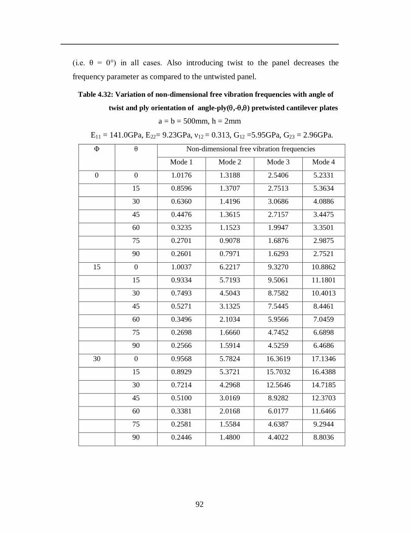
92
(i.e. θ = 0°) in all cases. Also introducing twist to the panel decreases the
frequency parameter as compared to the untwisted panel.
Table 4.32: Variation of non-dimensional free vibration frequencies with angle of
twist and ply orientation of angle-ply(,-,) pretwisted cantilever plates
a = b = 500mm, h = 2mm
E11 = 141.0GPa, E22= 9.23GPa, ν12 = 0.313, G12 =5.95GPa, G23 = 2.96GPa.
Φ θ Non-dimensional free vibration frequencies
Mode 1 Mode 2 Mode 3 Mode 4
0 0 1.0176 1.3188 2.5406 5.2331
15 0.8596 1.3707 2.7513 5.3634
30 0.6360 1.4196 3.0686 4.0886
45 0.4476 1.3615 2.7157 3.4475
60 0.3235 1.1523 1.9947 3.3501
75 0.2701 0.9078 1.6876 2.9875
90 0.2601 0.7971 1.6293 2.7521
15 0 1.0037 6.2217 9.3270 10.8862
15 0.9334 5.7193 9.5061 11.1801
30 0.7493 4.5043 8.7582 10.4013
45 0.5271 3.1325 7.5445 8.4461
60 0.3496 2.1034 5.9566 7.0459
75 0.2698 1.6660 4.7452 6.6898
90 0.2566 1.5914 4.5259 6.4686
30 0 0.9568 5.7824 16.3619 17.1346
15 0.8929 5.3721 15.7032 16.4388
30 0.7214 4.2968 12.5646 14.7185
45 0.5100 3.0169 8.9282 12.3703
60 0.3381 2.0168 6.0177 11.6466
75 0.2581 1.5584 4.6387 9.2944
90 0.2446 1.4800 4.4022 8.8036
93
The free vibration frequencies of the four lowest modes of vibration of
composite angle-ply pretwisted cantilever curved panels (twisted plate with
camber) are presented in Table 4.33. For a particular stacking sequence, as the
angle of twist increases, the non-dimensional fundamental frequency decreases in
all cases. There is significant increase in non-dimensional frequencies of higher
modes with increase in the angle of twist. As shown in Table 4.33, the non-
dimensional fundamental frequency of the twisted curved panel decreases with
introduction of twist. Comparing the frequencies in Table 4.32 with that given in
Table 4.33, it is also observed that introducing curvature to the plate increases the
stiffness and hence the non-dimensional frequency.
Table 4.34 shows the variation of non-dimensional fundamental
frequency with increasing Ry /b ratio. The angle of twist of all the panels is taken
as 15°. It is observed that as the Ry /b ratio increases, the non-dimensional
frequency parameter decreases for all the ply orientations.
The effects of variation of aspect ratio are studied for a three layer
twisted plate with the angle of twist taken as 15° and are shown in Table 4.35. It
can be seen that as the aspect ratio increases for a particular ply orientation, the
non-dimensional frequency decreases suggesting a decrease in stiffness. For the
0° ply orientation, there is a slight increase after which the frequency parameter
decreases with increase in aspect ratio. For both 0° and 90° lay-ups the difference
in non-dimensional frequency parameter is marginal with the changing aspect
ratio as compared to the other stacking sequences.
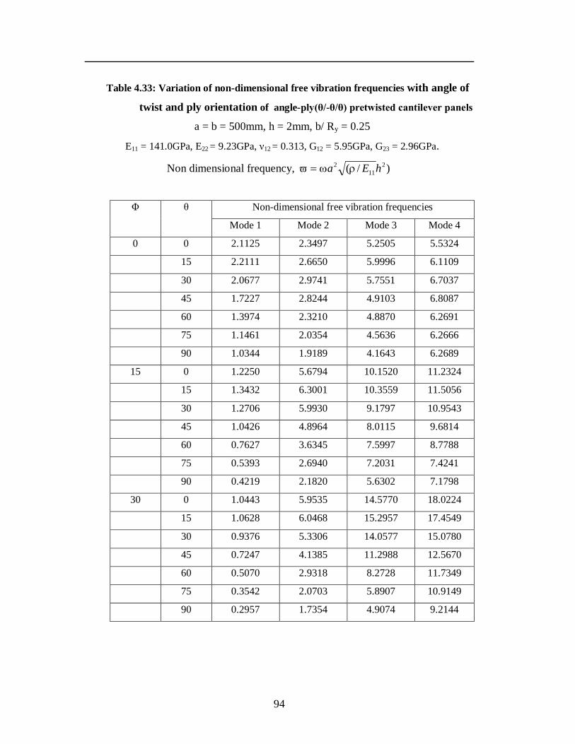
94
Table 4.33: Variation of non-dimensional free vibration frequencies with angle of
twist and ply orientation of angle-ply(θ/-θ/θ) pretwisted cantilever panels
a = b = 500mm, h = 2mm, b/ Ry = 0.25
E11 = 141.0GPa, E22 = 9.23GPa, ν12 = 0.313, G12 = 5.95GPa, G23 = 2.96GPa.
Non dimensional frequency, )/( 211
2 hEa
Φ θ Non-dimensional free vibration frequencies
Mode 1 Mode 2 Mode 3 Mode 4
0 0 2.1125 2.3497 5.2505 5.5324
15 2.2111 2.6650 5.9996 6.1109
30 2.0677 2.9741 5.7551 6.7037
45 1.7227 2.8244 4.9103 6.8087
60 1.3974 2.3210 4.8870 6.2691
75 1.1461 2.0354 4.5636 6.2666
90 1.0344 1.9189 4.1643 6.2689
15 0 1.2250 5.6794 10.1520 11.2324
15 1.3432 6.3001 10.3559 11.5056
30 1.2706 5.9930 9.1797 10.9543
45 1.0426 4.8964 8.0115 9.6814
60 0.7627 3.6345 7.5997 8.7788
75 0.5393 2.6940 7.2031 7.4241
90 0.4219 2.1820 5.6302 7.1798
30 0 1.0443 5.9535 14.5770 18.0224
15 1.0628 6.0468 15.2957 17.4549
30 0.9376 5.3306 14.0577 15.0780
45 0.7247 4.1385 11.2988 12.5670
60 0.5070 2.9318 8.2728 11.7349
75 0.3542 2.0703 5.8907 10.9149
90 0.2957 1.7354 4.9074 9.2144
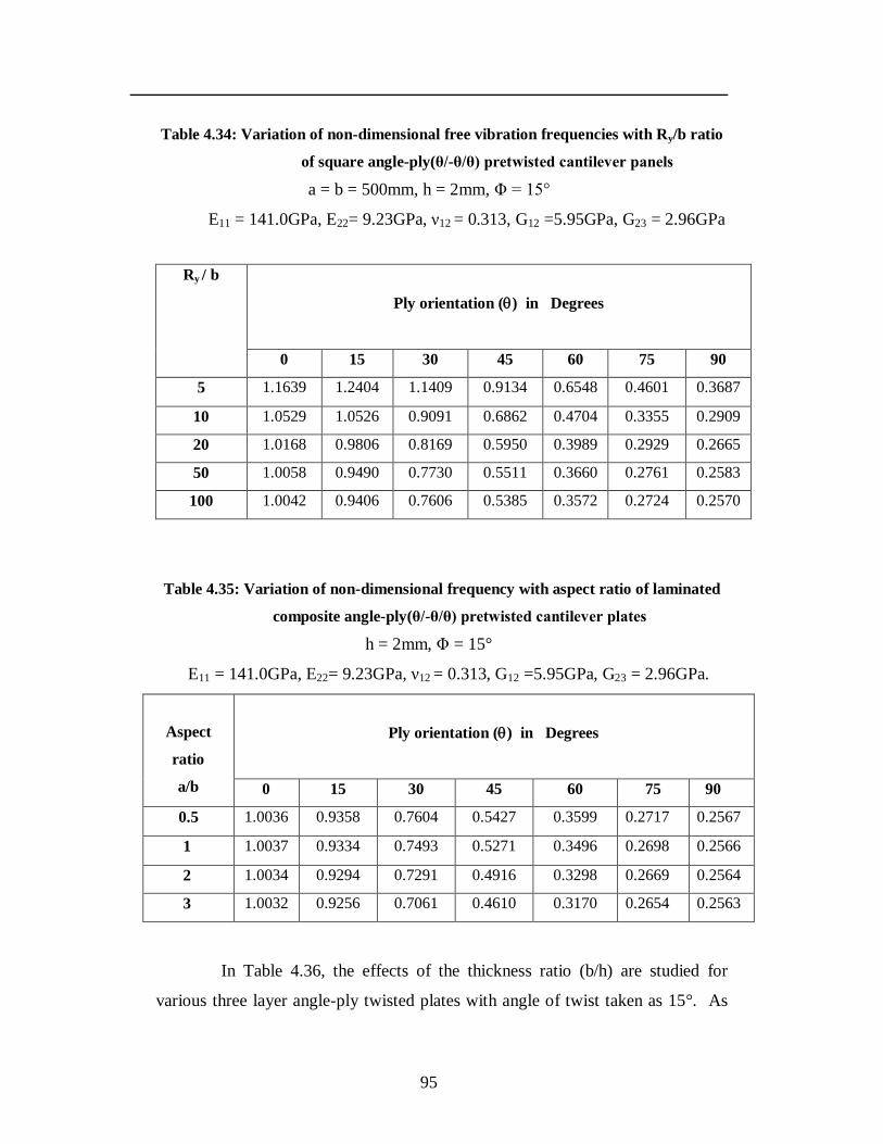
95
Table 4.34: Variation of non-dimensional free vibration frequencies with Ry/b ratio
of square angle-ply(θ/-θ/θ) pretwisted cantilever panels
a = b = 500mm, h = 2mm, Φ = 15°
E11 = 141.0GPa, E22= 9.23GPa, ν12 = 0.313, G12 =5.95GPa, G23 = 2.96GPa
Ry / b
Ply orientation () in Degrees
0 15 30 45 60 75 90
5 1.1639 1.2404 1.1409 0.9134 0.6548 0.4601 0.3687
10 1.0529 1.0526 0.9091 0.6862 0.4704 0.3355 0.2909
20 1.0168 0.9806 0.8169 0.5950 0.3989 0.2929 0.2665
50 1.0058 0.9490 0.7730 0.5511 0.3660 0.2761 0.2583
100 1.0042 0.9406 0.7606 0.5385 0.3572 0.2724 0.2570
Table 4.35: Variation of non-dimensional frequency with aspect ratio of laminated
composite angle-ply(θ/-θ/θ) pretwisted cantilever plates
h = 2mm, Φ = 15°
E11 = 141.0GPa, E22= 9.23GPa, ν12 = 0.313, G12 =5.95GPa, G23 = 2.96GPa.
Aspect
ratio
a/b
Ply orientation () in Degrees
0 15 30 45 60 75 90
0.5 1.0036 0.9358 0.7604 0.5427 0.3599 0.2717 0.2567
1 1.0037 0.9334 0.7493 0.5271 0.3496 0.2698 0.2566
2 1.0034 0.9294 0.7291 0.4916 0.3298 0.2669 0.2564
3 1.0032 0.9256 0.7061 0.4610 0.3170 0.2654 0.2563
In Table 4.36, the effects of the thickness ratio (b/h) are studied for
various three layer angle-ply twisted plates with angle of twist taken as 15°. As
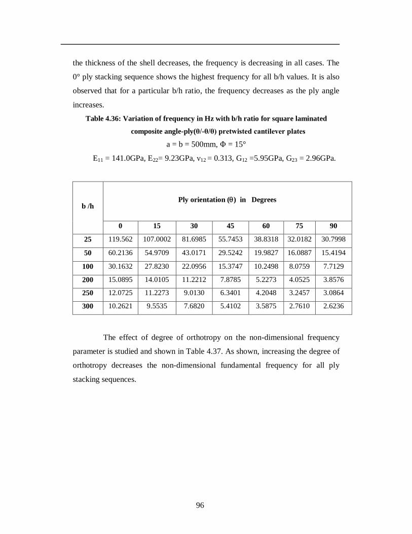
96
the thickness of the shell decreases, the frequency is decreasing in all cases. The
0° ply stacking sequence shows the highest frequency for all b/h values. It is also
observed that for a particular b/h ratio, the frequency decreases as the ply angle
increases.
Table 4.36: Variation of frequency in Hz with b/h ratio for square laminated
composite angle-ply(θ/-θ/θ) pretwisted cantilever plates
a = b = 500mm, Φ = 15°
E11 = 141.0GPa, E22= 9.23GPa, ν12 = 0.313, G12 =5.95GPa, G23 = 2.96GPa.
b /h
Ply orientation () in Degrees
0 15 30 45 60 75 90
25 119.562 107.0002 81.6985 55.7453 38.8318 32.0182 30.7998
50 60.2136 54.9709 43.0171 29.5242 19.9827 16.0887 15.4194
100 30.1632 27.8230 22.0956 15.3747 10.2498 8.0759 7.7129
200 15.0895 14.0105 11.2212 7.8785 5.2273 4.0525 3.8576
250 12.0725 11.2273 9.0130 6.3401 4.2048 3.2457 3.0864
300 10.2621 9.5535 7.6820 5.4102 3.5875 2.7610 2.6236
The effect of degree of orthotropy on the non-dimensional frequency
parameter is studied and shown in Table 4.37. As shown, increasing the degree of
orthotropy decreases the non-dimensional fundamental frequency for all ply
stacking sequences.
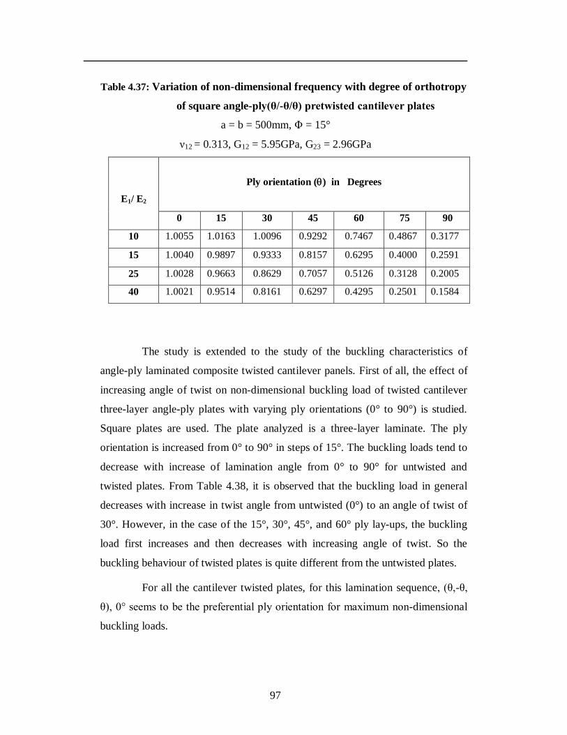
97
Table 4.37: Variation of non-dimensional frequency with degree of orthotropy
of square angle-ply(θ/-θ/θ) pretwisted cantilever plates
a = b = 500mm, Φ = 15°
ν12 = 0.313, G12 = 5.95GPa, G23 = 2.96GPa
E1/ E2
Ply orientation () in Degrees
0 15 30 45 60 75 90
10 1.0055 1.0163 1.0096 0.9292 0.7467 0.4867 0.3177
15 1.0040 0.9897 0.9333 0.8157 0.6295 0.4000 0.2591
25 1.0028 0.9663 0.8629 0.7057 0.5126 0.3128 0.2005
40 1.0021 0.9514 0.8161 0.6297 0.4295 0.2501 0.1584
The study is extended to the study of the buckling characteristics of
angle-ply laminated composite twisted cantilever panels. First of all, the effect of
increasing angle of twist on non-dimensional buckling load of twisted cantilever
three-layer angle-ply plates with varying ply orientations (0° to 90°) is studied.
Square plates are used. The plate analyzed is a three-layer laminate. The ply
orientation is increased from 0° to 90° in steps of 15°. The buckling loads tend to
decrease with increase of lamination angle from 0° to 90° for untwisted and
twisted plates. From Table 4.38, it is observed that the buckling load in general
decreases with increase in twist angle from untwisted (0°) to an angle of twist of
30°. However, in the case of the 15°, 30°, 45°, and 60° ply lay-ups, the buckling
load first increases and then decreases with increasing angle of twist. So the
buckling behaviour of twisted plates is quite different from the untwisted plates.
For all the cantilever twisted plates, for this lamination sequence, (θ,-θ,
θ), 0° seems to be the preferential ply orientation for maximum non-dimensional
buckling loads.
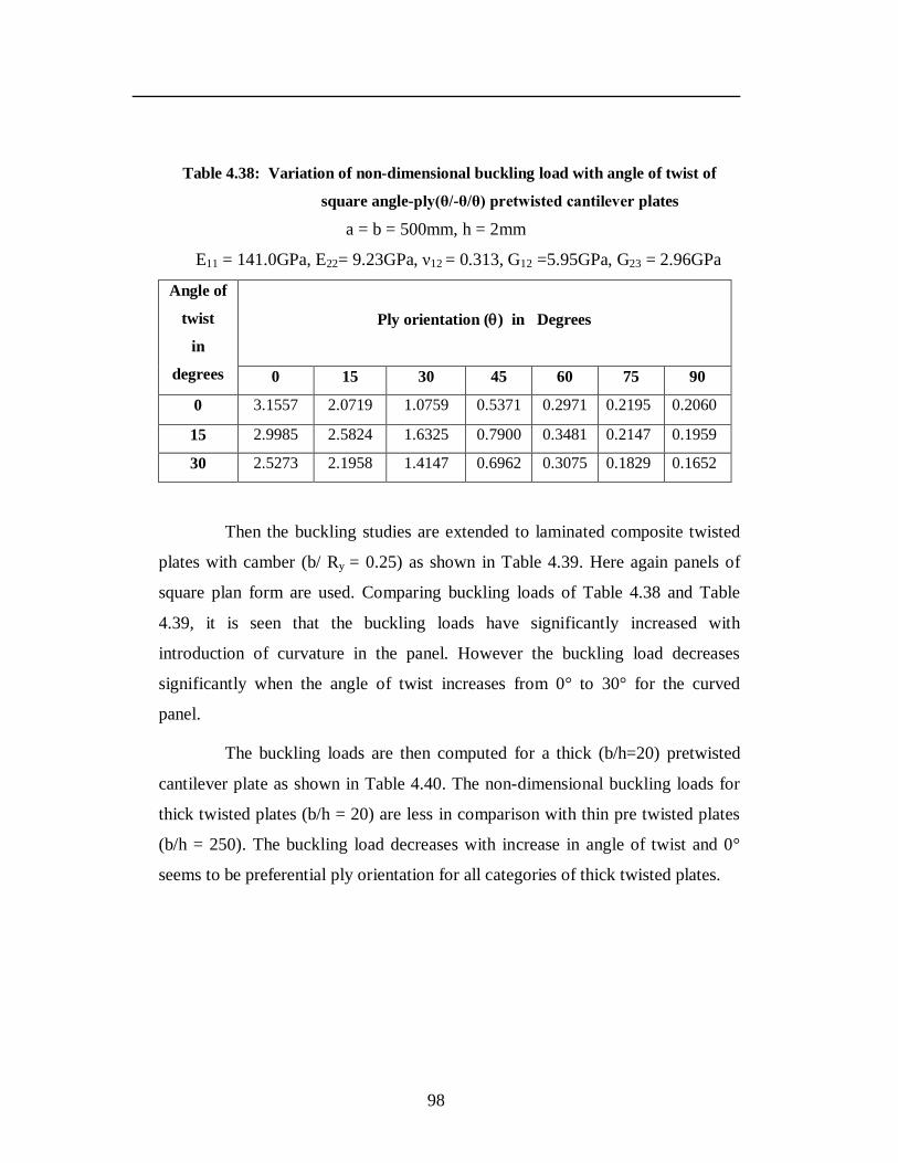
98
Table 4.38: Variation of non-dimensional buckling load with angle of twist of
square angle-ply(θ/-θ/θ) pretwisted cantilever plates
a = b = 500mm, h = 2mm
E11 = 141.0GPa, E22= 9.23GPa, ν12 = 0.313, G12 =5.95GPa, G23 = 2.96GPa
Angle of
twist
in
degrees
Ply orientation () in Degrees
0 15 30 45 60 75 90
0 3.1557 2.0719 1.0759 0.5371 0.2971 0.2195 0.2060
15 2.9985 2.5824 1.6325 0.7900 0.3481 0.2147 0.1959
30 2.5273 2.1958 1.4147 0.6962 0.3075 0.1829 0.1652
Then the buckling studies are extended to laminated composite twisted
plates with camber (b/ Ry = 0.25) as shown in Table 4.39. Here again panels of
square plan form are used. Comparing buckling loads of Table 4.38 and Table
4.39, it is seen that the buckling loads have significantly increased with
introduction of curvature in the panel. However the buckling load decreases
significantly when the angle of twist increases from 0° to 30° for the curved
panel.
The buckling loads are then computed for a thick (b/h=20) pretwisted
cantilever plate as shown in Table 4.40. The non-dimensional buckling loads for
thick twisted plates (b/h = 20) are less in comparison with thin pre twisted plates
(b/h = 250). The buckling load decreases with increase in angle of twist and 0°
seems to be preferential ply orientation for all categories of thick twisted plates.
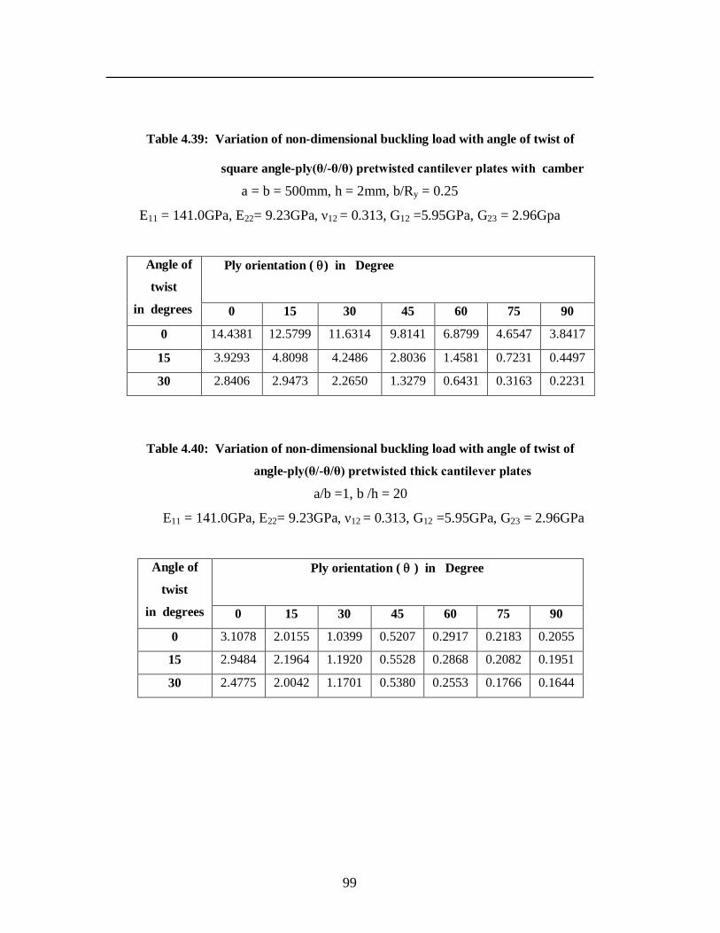
99
Table 4.39: Variation of non-dimensional buckling load with angle of twist of
square angle-ply(θ/-θ/θ) pretwisted cantilever plates with camber
a = b = 500mm, h = 2mm, b/Ry = 0.25
E11 = 141.0GPa, E22= 9.23GPa, ν12 = 0.313, G12 =5.95GPa, G23 = 2.96Gpa
Angle of
twist
in degrees
Ply orientation ( ) in Degree
0 15 30 45 60 75 90
0 14.4381 12.5799 11.6314 9.8141 6.8799 4.6547 3.8417
15 3.9293 4.8098 4.2486 2.8036 1.4581 0.7231 0.4497
30 2.8406 2.9473 2.2650 1.3279 0.6431 0.3163 0.2231
Table 4.40: Variation of non-dimensional buckling load with angle of twist of
angle-ply(θ/-θ/θ) pretwisted thick cantilever plates
a/b =1, b /h = 20
E11 = 141.0GPa, E22= 9.23GPa, ν12 = 0.313, G12 =5.95GPa, G23 = 2.96GPa
Angle of
twist
in degrees
Ply orientation ( ) in Degree
0 15 30 45 60 75 90
0 3.1078 2.0155 1.0399 0.5207 0.2917 0.2183 0.2055
15 2.9484 2.1964 1.1920 0.5528 0.2868 0.2082 0.1951
30 2.4775 2.0042 1.1701 0.5380 0.2553 0.1766 0.1644
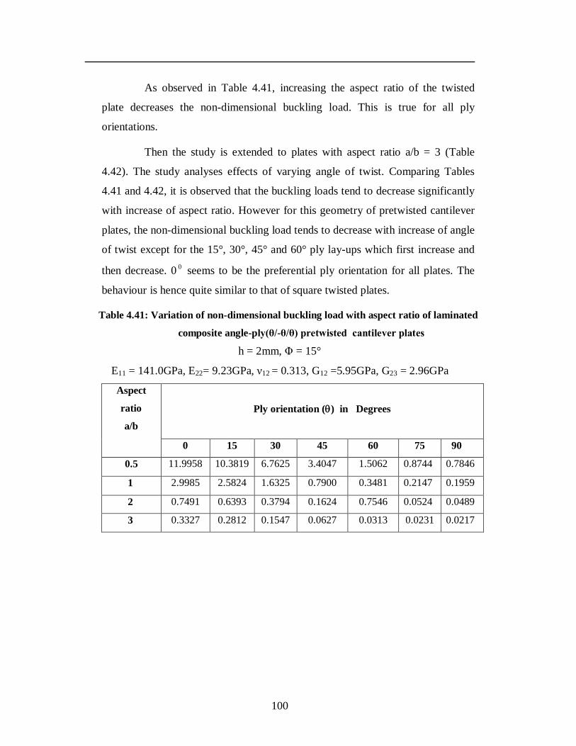
100
As observed in Table 4.41, increasing the aspect ratio of the twisted
plate decreases the non-dimensional buckling load. This is true for all ply
orientations.
Then the study is extended to plates with aspect ratio a/b = 3 (Table
4.42). The study analyses effects of varying angle of twist. Comparing Tables
4.41 and 4.42, it is observed that the buckling loads tend to decrease significantly
with increase of aspect ratio. However for this geometry of pretwisted cantilever
plates, the non-dimensional buckling load tends to decrease with increase of angle
of twist except for the 15°, 30°, 45° and 60° ply lay-ups which first increase and
then decrease. 0 0 seems to be the preferential ply orientation for all plates. The
behaviour is hence quite similar to that of square twisted plates.
Table 4.41: Variation of non-dimensional buckling load with aspect ratio of laminated
composite angle-ply(θ/-θ/θ) pretwisted cantilever plates
h = 2mm, Φ = 15°
E11 = 141.0GPa, E22= 9.23GPa, ν12 = 0.313, G12 =5.95GPa, G23 = 2.96GPa
Aspect
ratio
a/b
Ply orientation () in Degrees
0 15 30 45 60 75 90
0.5 11.9958 10.3819 6.7625 3.4047 1.5062 0.8744 0.7846
1 2.9985 2.5824 1.6325 0.7900 0.3481 0.2147 0.1959
2 0.7491 0.6393 0.3794 0.1624 0.7546 0.0524 0.0489
3 0.3327 0.2812 0.1547 0.0627 0.0313 0.0231 0.0217
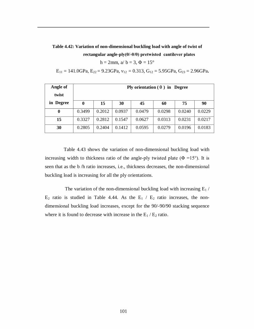
101
Table 4.42: Variation of non-dimensional buckling load with angle of twist of
rectangular angle-ply(θ/-θ/θ) pretwisted cantilever plates
h = 2mm, a/ b = 3, Φ = 15°
E11 = 141.0GPa, E22 = 9.23GPa, ν12 = 0.313, G12 = 5.95GPa, G23 = 2.96GPa.
Angle of
twist
in Degree
Ply orientation ( ) in Degree
0 15 30 45 60 75 90
0 0.3499 0.2012 0.0937 0.0479 0.0298 0.0240 0.0229
15 0.3327 0.2812 0.1547 0.0627 0.0313 0.0231 0.0217
30 0.2805 0.2404 0.1412 0.0595 0.0279 0.0196 0.0183
Table 4.43 shows the variation of non-dimensional buckling load with
increasing width to thickness ratio of the angle-ply twisted plate (Φ =15°). It is
seen that as the b /h ratio increases, i.e., thickness decreases, the non-dimensional
buckling load is increasing for all the ply orientations.
The variation of the non-dimensional buckling load with increasing E1 /
E2 ratio is studied in Table 4.44. As the E1 / E2 ratio increases, the non-
dimensional buckling load increases, except for the 90/-90/90 stacking sequence
where it is found to decrease with increase in the E1 / E2 ratio.
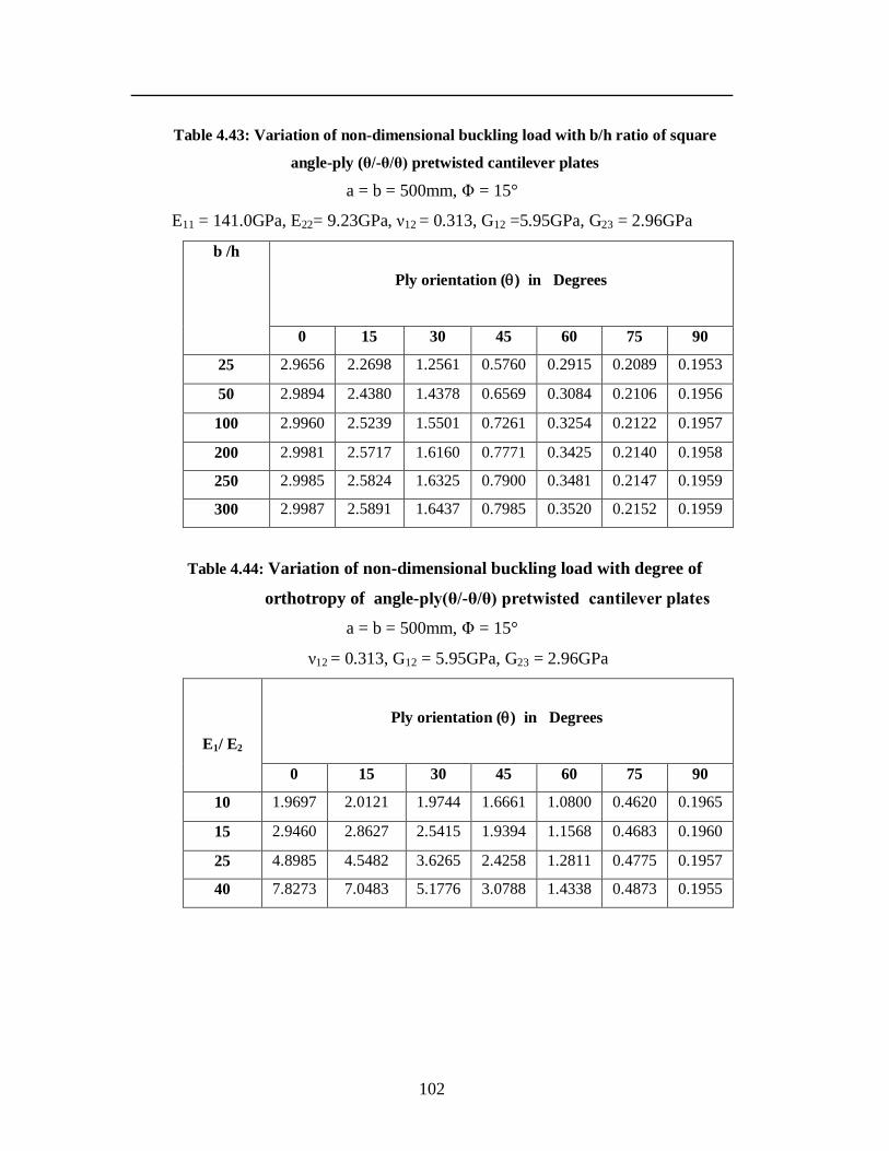
102
Table 4.43: Variation of non-dimensional buckling load with b/h ratio of square
angle-ply (θ/-θ/θ) pretwisted cantilever plates
a = b = 500mm, Φ = 15°
E11 = 141.0GPa, E22= 9.23GPa, ν12 = 0.313, G12 =5.95GPa, G23 = 2.96GPa
b /h
Ply orientation () in Degrees
0 15 30 45 60 75 90
25 2.9656 2.2698 1.2561 0.5760 0.2915 0.2089 0.1953
50 2.9894 2.4380 1.4378 0.6569 0.3084 0.2106 0.1956
100 2.9960 2.5239 1.5501 0.7261 0.3254 0.2122 0.1957
200 2.9981 2.5717 1.6160 0.7771 0.3425 0.2140 0.1958
250 2.9985 2.5824 1.6325 0.7900 0.3481 0.2147 0.1959
300 2.9987 2.5891 1.6437 0.7985 0.3520 0.2152 0.1959
Table 4.44: Variation of non-dimensional buckling load with degree of
orthotropy of angle-ply(θ/-θ/θ) pretwisted cantilever plates
a = b = 500mm, Φ = 15°
ν12 = 0.313, G12 = 5.95GPa, G23 = 2.96GPa
E1/ E2
Ply orientation () in Degrees
0 15 30 45 60 75 90
10 1.9697 2.0121 1.9744 1.6661 1.0800 0.4620 0.1965
15 2.9460 2.8627 2.5415 1.9394 1.1568 0.4683 0.1960
25 4.8985 4.5482 3.6265 2.4258 1.2811 0.4775 0.1957
40 7.8273 7.0483 5.1776 3.0788 1.4338 0.4873 0.1955
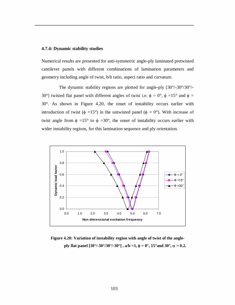
103
4.7.4: Dynamic stability studies
Numerical results are presented for anti-symmetric angle-ply laminated pretwisted
cantilever panels with different combinations of lamination parameters and
geometry including angle of twist, b/h ratio, aspect ratio and curvature.
The dynamic stability regions are plotted for angle-ply [30°/-30°/30°/-
30°] twisted flat panel with different angles of twist i.e. = 0°, =15° and =
30°. As shown in Figure 4.20, the onset of instability occurs earlier with
introduction of twist ( =15°) in the untwisted panel ( = 0°). With increase of
twist angle from =15° to =30°, the onset of instability occurs earlier with
wider instability regions, for this lamination sequence and ply orientation.
0.0
0.2
0.4
0.6
0.8
1.0
0.0 1.0 2.0 3.0 4.0 5.0 6.0 7.0
Non-dimensional excitation frequency
Dyn
amic
load
fact
or
Ф = 0°
Ф =15°
Ф =30°
Figure 4.20: Variation of instability region with angle of twist of the angle-
ply flat panel [30°/-30°/30°/-30°] , a/b =1, = 0°, 15°and 30°, = 0.2.
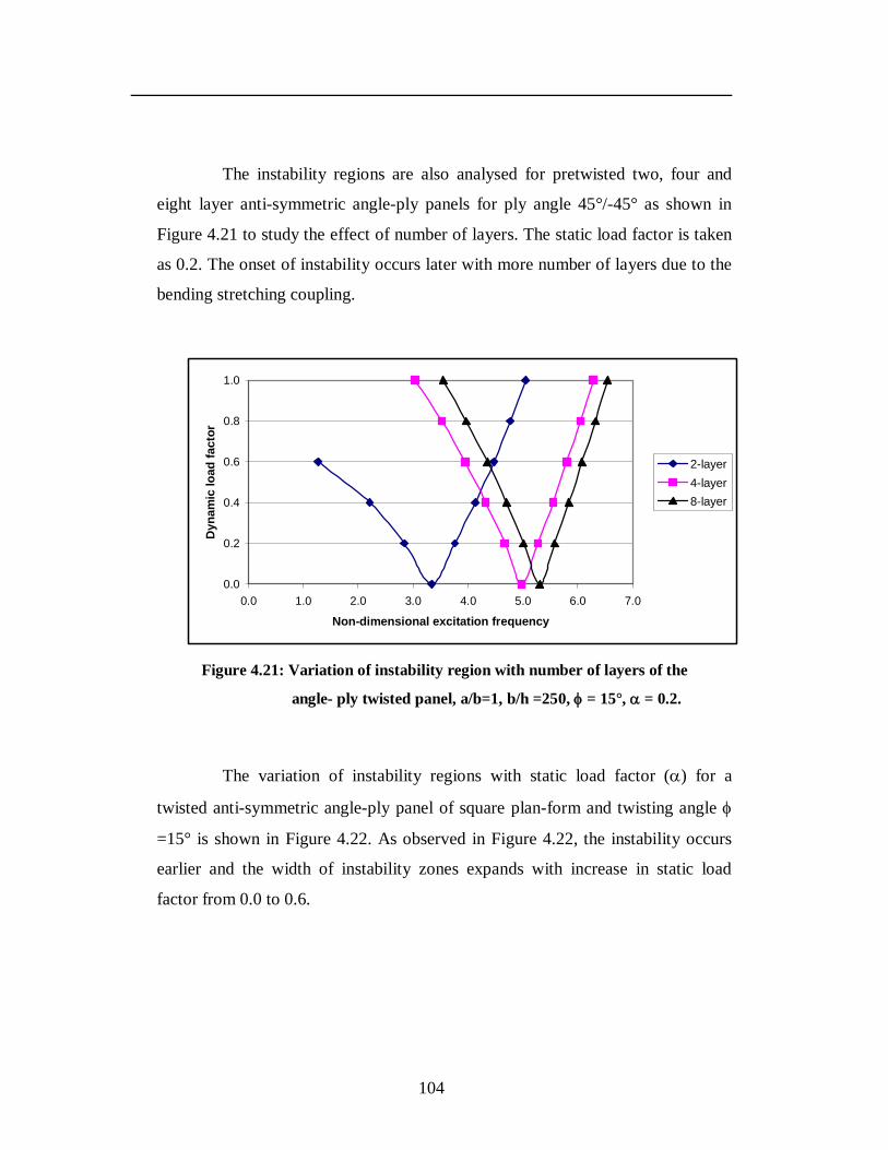
104
The instability regions are also analysed for pretwisted two, four and
eight layer anti-symmetric angle-ply panels for ply angle 45°/-45° as shown in
Figure 4.21 to study the effect of number of layers. The static load factor is taken
as 0.2. The onset of instability occurs later with more number of layers due to the
bending stretching coupling.
0.0
0.2
0.4
0.6
0.8
1.0
0.0 1.0 2.0 3.0 4.0 5.0 6.0 7.0
Non-dimensional excitation frequency
Dyn
amic
load
fact
or
2-layer4-layer8-layer
Figure 4.21: Variation of instability region with number of layers of the
angle- ply twisted panel, a/b=1, b/h =250, = 15°, = 0.2.
The variation of instability regions with static load factor () for a
twisted anti-symmetric angle-ply panel of square plan-form and twisting angle
=15° is shown in Figure 4.22. As observed in Figure 4.22, the instability occurs
earlier and the width of instability zones expands with increase in static load
factor from 0.0 to 0.6.
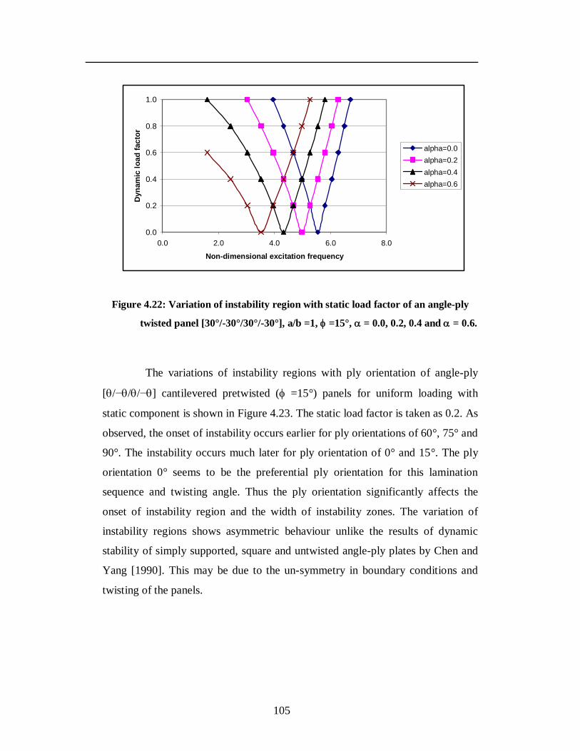
105
0.0
0.2
0.4
0.6
0.8
1.0
0.0 2.0 4.0 6.0 8.0
Non-dimensional excitation frequency
Dyn
amic
load
fact
oralpha=0.0alpha=0.2alpha=0.4alpha=0.6
Figure 4.22: Variation of instability region with static load factor of an angle-ply
twisted panel [30°/-30°/30°/-30°], a/b =1, =15°, = 0.0, 0.2, 0.4 and = 0.6.
The variations of instability regions with ply orientation of angle-ply
[/−//−] cantilevered pretwisted ( =15°) panels for uniform loading with
static component is shown in Figure 4.23. The static load factor is taken as 0.2. As
observed, the onset of instability occurs earlier for ply orientations of 60°, 75° and
90°. The instability occurs much later for ply orientation of 0° and 15°. The ply
orientation 0° seems to be the preferential ply orientation for this lamination
sequence and twisting angle. Thus the ply orientation significantly affects the
onset of instability region and the width of instability zones. The variation of
instability regions shows asymmetric behaviour unlike the results of dynamic
stability of simply supported, square and untwisted angle-ply plates by Chen and
Yang [1990]. This may be due to the un-symmetry in boundary conditions and
twisting of the panels.
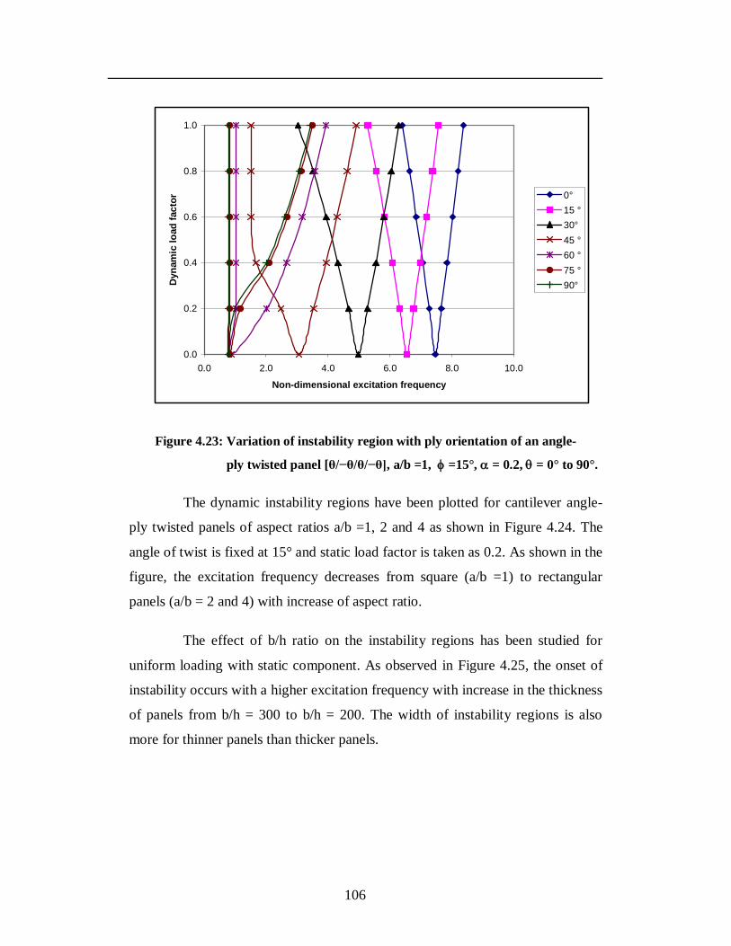
106
0.0
0.2
0.4
0.6
0.8
1.0
0.0 2.0 4.0 6.0 8.0 10.0
Non-dimensional excitation frequency
Dyn
amic
load
fact
or 0°15 °30°45 °60 °75 °90°
Figure 4.23: Variation of instability region with ply orientation of an angle-
ply twisted panel [θ/−θ/θ/−θ], a/b =1, =15°, = 0.2, = 0° to 90°.
The dynamic instability regions have been plotted for cantilever angle-
ply twisted panels of aspect ratios a/b =1, 2 and 4 as shown in Figure 4.24. The
angle of twist is fixed at 15° and static load factor is taken as 0.2. As shown in the
figure, the excitation frequency decreases from square (a/b =1) to rectangular
panels (a/b = 2 and 4) with increase of aspect ratio.
The effect of b/h ratio on the instability regions has been studied for
uniform loading with static component. As observed in Figure 4.25, the onset of
instability occurs with a higher excitation frequency with increase in the thickness
of panels from b/h = 300 to b/h = 200. The width of instability regions is also
more for thinner panels than thicker panels.

107
0.0
0.2
0.4
0.6
0.8
1.0
0.0 1.0 2.0 3.0 4.0 5.0 6.0 7.0
Non-dimensional excitation frequency
Dyn
amic
load
fact
or
a/b =1a/b =2a/b =4
Figure 4.24: Variation of instability region with aspect ratio of the angle-ply twisted
panel [30°/-30°/30°/-30°], a/b =1, 2 and 4, =15°, = 0.2.
0.0
0.2
0.4
0.6
0.8
1.0
0.0 2.0 4.0 6.0 8.0
Non-dimensional excitation frequency
Dyn
amic
load
fact
or
b/h = 200b/h = 250b/h = 300
Figure 4.25: Variation of instability region with b/h ratio of the angle-ply twisted panel [30°/-30°/30°/-30°], a/b =1, b/h = 200, 250, 300, =15°, = 0.2.
The variation of instability regions is studied for anti-symmetric angle-
ply pretwisted cylindrical panels (b/Ry = 0.25) to study the effect of angle of twist
on the curved panel. As seen from Figure 4.26, there is significant deviation of the
instability behaviour of twisted cylindrical panels than that of untwisted panels.
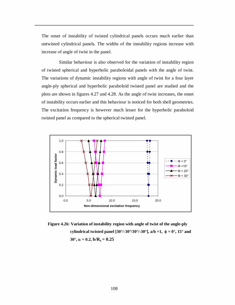
108
The onset of instability of twisted cylindrical panels occurs much earlier than
untwisted cylindrical panels. The widths of the instability regions increase with
increase of angle of twist in the panel.
Similar behaviour is also observed for the variation of instability region
of twisted spherical and hyperbolic paraboloidal panels with the angle of twist.
The variations of dynamic instability regions with angle of twist for a four layer
angle-ply spherical and hyperbolic paraboloid twisted panel are studied and the
plots are shown in figures 4.27 and 4.28. As the angle of twist increases, the onset
of instability occurs earlier and this behaviour is noticed for both shell geometries.
The excitation frequency is however much lesser for the hyperbolic paraboloid
twisted panel as compared to the spherical twisted panel.
0.0
0.2
0.4
0.6
0.8
1.0
0.0 5.0 10.0 15.0 20.0
Non-dimensional excitation frequency
Dyn
amic
load
fact
or
Φ = 0°Φ =15°Φ = 20°Φ = 30°
Figure 4.26: Variation of instability region with angle of twist of the angle-ply
cylindrical twisted panel [30°/-30°/30°/-30°], a/b =1, = 0°, 15° and
30°, = 0.2, b/Ry = 0.25
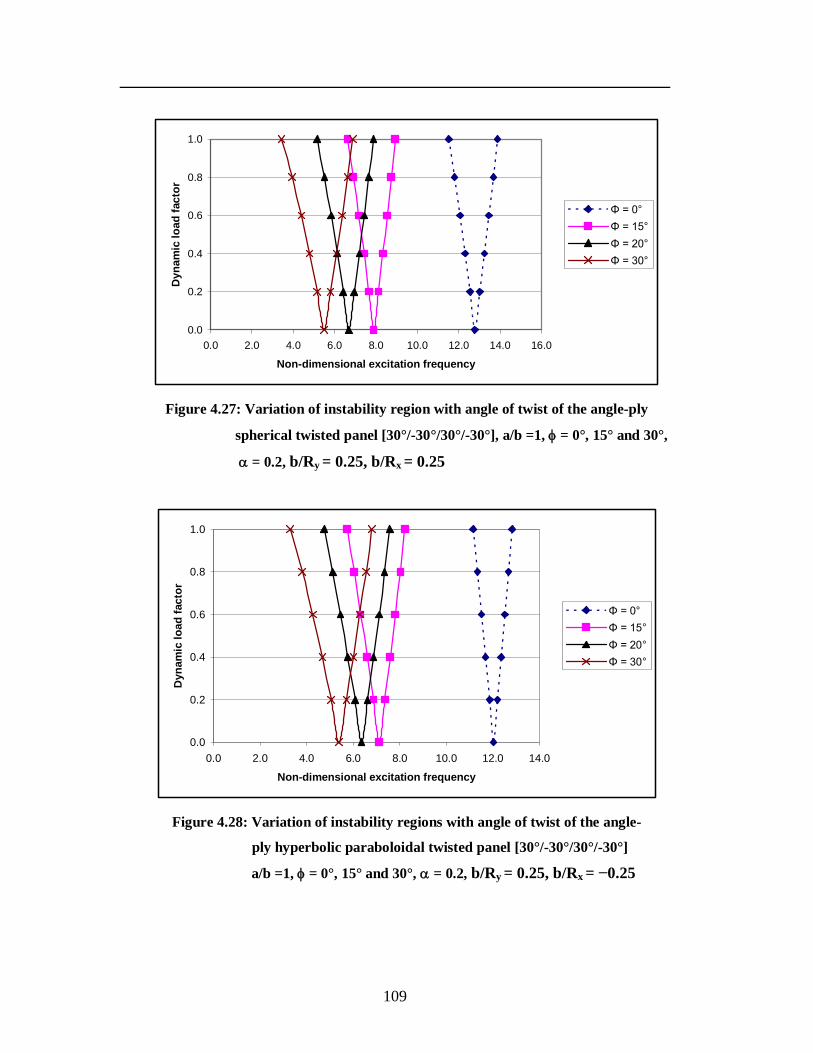
109
0.0
0.2
0.4
0.6
0.8
1.0
0.0 2.0 4.0 6.0 8.0 10.0 12.0 14.0 16.0
Non-dimensional excitation frequency
Dyn
amic
load
fact
or
Φ = 0°Φ = 15°Φ = 20°Φ = 30°
Figure 4.27: Variation of instability region with angle of twist of the angle-ply
spherical twisted panel [30°/-30°/30°/-30°], a/b =1, = 0°, 15° and 30°,
= 0.2, b/Ry = 0.25, b/Rx = 0.25
0.0
0.2
0.4
0.6
0.8
1.0
0.0 2.0 4.0 6.0 8.0 10.0 12.0 14.0
Non-dimensional excitation frequency
Dyn
amic
load
fact
or
Φ = 0°Φ = 15°Φ = 20°Φ = 30°
Figure 4.28: Variation of instability regions with angle of twist of the angle-
ply hyperbolic paraboloidal twisted panel [30°/-30°/30°/-30°]
a/b =1, = 0°, 15° and 30°, = 0.2, b/Ry = 0.25, b/Rx = −0.25
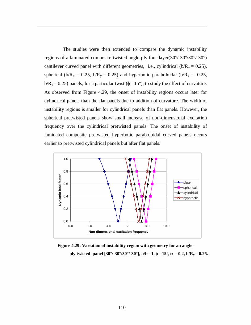
110
The studies were then extended to compare the dynamic instability
regions of a laminated composite twisted angle-ply four layer(30°/-30°/30°/-30°)
cantilever curved panel with different geometries, i.e., cylindrical (b/Ry = 0.25),
spherical (b/Rx = 0.25, b/Ry = 0.25) and hyperbolic paraboloidal (b/Rx = -0.25,
b/Ry = 0.25) panels, for a particular twist ( =15°), to study the effect of curvature.
As observed from Figure 4.29, the onset of instability regions occurs later for
cylindrical panels than the flat panels due to addition of curvature. The width of
instability regions is smaller for cylindrical panels than flat panels. However, the
spherical pretwisted panels show small increase of non-dimensional excitation
frequency over the cylindrical pretwisted panels. The onset of instability of
laminated composite pretwisted hyperbolic paraboloidal curved panels occurs
earlier to pretwisted cylindrical panels but after flat panels.
0.0
0.2
0.4
0.6
0.8
1.0
0.0 2.0 4.0 6.0 8.0 10.0
Non-dimensional excitation frequency
Dyn
amic
load
fact
or
platesphericalcylindricalhyperbolic
Figure 4.29: Variation of instability region with geometry for an angle-
ply twisted panel [30°/-30°/30°/-30°], a/b =1, =15°, = 0.2, b/Ry = 0.25.
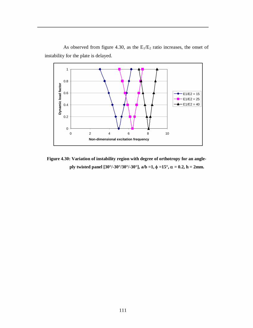
111
As observed from figure 4.30, as the E1/E2 ratio increases, the onset of
instability for the plate is delayed.
0
0.2
0.4
0.6
0.8
1
0 2 4 6 8 10
Non-dimensional excitation frequency
Dyn
amic
load
fact
or
E1/E2 = 15E1/E2 = 25E1/E2 = 40
Figure 4.30: Variation of instability region with degree of orthotropy for an angle-
ply twisted panel [30°/-30°/30°/-30°], a/b =1, =15°, = 0.2, h = 2mm.
112
CHAPTER 5
CONCLUSIONS
The present work deals with the study of the vibration, buckling and parametric
resonance characteristics of homogeneous, cross-ply and angle-ply laminated
composite twisted cantilever panels. The formulation is based on the first order
shear deformation theory, taking into account transverse shear and rotary inertia
effects. A finite element procedure using an eight-node isoparametric quadratic
shell element is employed in the present analysis with five degrees of freedom per
node. The development of regions of instability arises from Floquet’s theory
developed by Bolotin and the boundaries of the primary instability regions with
period 2T, where T = 2 /Ω which are of practical importance have been
determined to study the effect of various parameters of the laminated composite
twisted panels on the dynamic instability regions.
Results are presented for the vibration, buckling and dynamic stability
characteristics for isotropic, cross-ply and angle-ply laminated composite twisted
cantilever panels. The effects of various geometrical parameters like angle of
twist, aspect ratio, shallowness ratio and lamination details (for composite panels)
on the vibration and stability characteristics of isotropic and laminated
composite(cross-ply and angle-ply) twisted cantilever panels has been analysed.
The conclusions are presented separately for these three cases.
113
5.1: Isotropic twisted panels
The effect of various parameters on the vibration and stability characteristics of
the isotropic twisted panel has been studied. The results can be summarized as
follows.
Introduction of an angle of twist of 10° to the untwisted plate is seen to
reduce the fundamental frequency parameter by 0.5%. It is also seen that
as the angle of twist increases, the lowest non-dimensional frequency
parameter decreases.
Introducing a curvature to the twisted panel increases the non-dimensional
frequency parameter suggesting an increase in the stiffness of the panel
due to addition of curvature.
The frequency parameter of the twisted isotropic panel decreases as the
aspect ratio increases.
As the thickness of the plate decreases, the frequency of vibration in Hz
decreases.
Twisted curved panels with various geometries were also studied and it is
observed that all the twisted panels with curvature have greater frequency
parameter than the flat twisted panel. The fundamental frequency
parameter is highest for the spherical twisted panel and is 35.1% greater
than the twisted flat panel.
The lowest non-dimensional buckling load decreases as the angle of twist
of the plate increases. Introduction of an angle of twist of 10° to the
untwisted plate decreases the buckling load by 1.9% and at an angle of
twist of 30°, the decrease in the lowest buckling load is as much as 18%
compared to the untwisted panel.
114
The buckling load significantly increases with introduction of curvature to
the plate. The buckling load for an untwisted square cylindrical panel is
726.9% more than the untwisted square plate. The buckling load of the
cylindrical cantilever panel decreases as the angle of twist increases.
As the Ry /b ratio increases, the non-dimensional buckling load decreases.
Increasing the aspect ratio is found to decrease the non-dimensional
buckling load of the twisted panel.
An increase in the b/h ratio of the twisted panel contributes to a decrease
in the buckling load.
The instability occurs at lower excitation frequency as the angle of twist of
the panel increases and the width of the instability region is found to
decrease as the angle of twist decreases.
The effect of static load factor variation on the dynamic instability region
shows that the instability occurs earlier for higher static load factor and the
width of instability zones decreases with the decrease in the static load
factor. The variation was studied changing the static load factor from
0.2 to 0.6 for angle of twist =15°.
As the Ry /b ratio increases, the instability occurs at an earlier frequency
and the width of the instability region increases.
Increase in the b/h ratio causes the instability to occur earlier and the
width of the instability region to increase.
Comparing twisted curved panels with different geometries, it is seen that
the onset of instability occurs earlier for the flat panel. It occurs at a higher
excitation frequency for cylindrical panels than the hyperbolic
paraboloidal twisted panels and at a still higher excitation frequency for
the spherical twisted panel, though the spherical and cylindrical twisted
115
panels show little difference of excitation frequencies for instability. The
width of the instability region is marginally smaller for the cylindrical
panel than the hyperbolic paraboloid twisted panel.
5.2: Cross-ply twisted cantilever panels
The study has been carried out extensively for vibration, buckling and parametric
resonance characteristics of symmetric and anti-symmetric cross-ply lay-ups.
Two, four and eight layer antisymmetric lay-ups as well as a four layer symmetric
cross-ply lay-up are taken for the study.
It is found that as the angle of twist increases for a particular cross-ply
orientation, the frequency parameter decreases. This is true for both the
symmetric as well as antisymmetric cross-ply stacking sequences.
As the R/a ratio increases, the non-dimensional frequency parameter
decreases. Also for a particular cross-ply orientation and low R/a ratio, the
spherical shell shows slightly higher frequency parameter than the
cylindrical shell. Hence introduction of curvature increases the non-
dimensional frequency parameter suggesting an increase in the stiffness of
the shell with curvature.
As the aspect ratio increases, the non-dimensional frequency parameter
first slightly increases and then decreases gradually for all the stacking
sequences except in the two-layer stacking sequence which decreases with
increase in the aspect ratio.
With decrease in the thickness of the plate, the frequency in Hz decreases.
This is seen to be true for both symmetric and antisymmetric cross-ply
stacking sequences.
As the degree of orthotropy increases, the non-dimensional frequency
parameter decreases.
116
The introduction of twist to an untwisted plate is also seen to give lesser
non-dimensional buckling load values. Comparing the antisymmetric lay-
ups, for a particular angle of twist, the non-dimensional buckling load
increases as the number of layers increases.
The analysis of the non-dimensional buckling load for different
laminations of a square cylindrical and spherical shell with angle of twist
of 15° shows that the buckling load is found to decrease with increase of
R/a ratio for all cross-ply lay-ups. The symmetric arrangement of the plies
shows the greatest non-dimensional buckling load for a particular R/a
ratio.
It is observed that introduction of curvature to the plate increases the non-
dimensional buckling load. Comparing a square spherical twisted panel
and a square twisted plate, the buckling load is greater for the spherical
twisted panel.
Increase of aspect ratio is found to decrease the non-dimensional buckling
load.
As the thickness of the twisted plate decreases, the buckling load
decreases for all the ply orientations
With the increasing E1/ E2 ratio, the non-dimensional buckling load is
found to increase for all the cross-ply twisted plates.
The onset of instability occurs earlier with introduction of twist ( =10°)
in the untwisted panel ( = 0°). With increase of twist angle from =10°
to = 30°, the instability frequency decreases and the widths of the
instability region also decrease slightly as the angle of twist decreases.
To study the effect of number of layers on the dynamic instability regions,
two layer [0°/90°], four layer [0°/90°/0°/90°] and eight layer
117
[0°/90°/0°/90°/0°/90°/0°/90°] cross-ply twisted panels with angle of twist
taken as 15° were studied. The static load factor is taken as 0.2. The two
layer panel reaches dynamic instability earliest and the eight layer cross-
ply reaches dynamic instability latest. The width of the instability region
is different with two layer lay-up showing most width and the eight layer
cross-ply twisted plate showing the least width. This behaviour is also
noticed for the twisted spherical, cylindrical and hyperbolic paraboloidal
twisted panel where again the effect of number of layers is studied.
The instability occurs earlier for higher static load factor and the width of
instability zones decreases with decrease in static load factor.
As the aspect ratio increases, the instability occurs earlier and the width of
the instability region increases.
The onset of instability occurs with a lesser excitation frequency for thin
plates and occurs later as the thickness increases. The width of instability
regions is also more for thinner plates than thicker plates.
The onset of instability of laminated composite twisted cylindrical panels
occurs earlier than twisted spherical panels but later than twisted
hyperbolic panels. The width of instability regions is smaller for
cylindrical panels than hyperbolic twisted panels. Similar behaviour is
noticed in the four layer symmetric and eight layer antisymmetric cross-
ply twisted panels. The four layer lay-up shows much larger excitation
frequencies than the two or eight layer antisymmetric twisted cross-ply
panels for a particular shell geometry. The earliest instability frequency is
shown by plates in all cases.
The instability frequency increases as the E1/E2 ratio increases.
118
5.3: Angle-ply twisted cantilever panels
The studies are finally extended to examine in detail the effects of various
parameters on the stability of laminated composite, pretwisted angle-ply
cantilever plates/panels. The study has been carried out extensively for vibration,
buckling and parametric resonance characteristics of symmetric and
antisymmetric angle-ply lay-ups. For the vibration and buckling studies, three
layer symmetric angle-ply panels with varying ply orientation (0° to 90°) were
studied while for buckling studies four layer antisymmetric lay-up is assumed.
The first frequency parameter decreases with increase in the angle of twist
for the 0°/-0°/0°, 75°/-75°/75° and 90°/-90°/90° stacking sequence. For the
other stacking sequences the first frequency first increases and then
decreases with increase in the angle of twist. The maximum fundamental
frequencies are observed when the fibers are perpendicular to the clamped
edge (i.e. θ = 0°) in all cases. Also introducing twist to the plate decreases
the frequency parameter as compared to the untwisted plate.
For plates with camber, for a particular stacking sequence, as the angle of
twist increases, the non-dimensional fundamental frequency decreases in
all cases. There is significant increase in non-dimensional frequencies of
higher modes with increase in the angle of twist.
Introducing curvature to the plate increases the stiffness and hence the
non-dimensional frequency.
As the Ry /b ratio increases, the non-dimensional frequency parameter
decreases for all the ply orientations.
As the aspect ratio increases for a particular ply orientation, the non-
dimensional frequency decreases suggesting a decrease in stiffness.
119
As the thickness of the shell decreases, the frequency in Hz is decreasing
in all cases. The 0° ply stacking sequence shows the highest frequency for
all b/h values. It is also observed that for a particular b/h ratio, the
frequency decreases as the ply angle increases.
Increasing the degree of orthotropy decreases the non-dimensional
fundamental frequency for all ply stacking sequences.
The buckling loads tend to decrease with increase of lamination angle
from 0° to 90° for untwisted and twisted plates.
The buckling load in general decreases with increase in twist angle from
untwisted (0°) to an angle of twist of 30°. However in the case of the 15°,
30°, 45°, and 60° ply lay-ups, the buckling load first increases and then
decreases with increasing angle of twist. So the buckling behaviour of
twisted plates is quite different from the untwisted plates.
For all the cantilever twisted plates, for this lamination, (θ,-θ, θ), 0° seems
to be the preferential ply orientation for maximum non-dimensional
buckling loads.
The buckling load decreases with increase in angle of twist and 0° seems
to be preferential ply orientation for all categories of thick twisted plates
The buckling loads significantly increase with introduction of curvature in
the panel. However the buckling load decreases significantly when the
angle of twist increases from 0° to 30° for the curved panel.
Increasing the aspect ratio of the twisted plate decreases the non-
dimensional buckling load. This is true for all ply orientations.
As the b /h ratio increases, i.e., thickness decreases, the non-dimensional
buckling load is increasing for all the ply orientations
120
As the E1 / E2 ratio increases, the non-dimensional buckling load
increases, except for the 90/-90/90 stacking sequence where it is found to
decrease with increase in the E1 / E2 ratio.
The onset of instability occurs earlier with introduction of twist ( =15°)
in the untwisted panel ( = 0°). With increase of twist angle from =15°
to =30°, the onset of instability occurs earlier with wider instability
regions.
The onset of instability occurs later with more number of layers due to the
bending stretching coupling.
Varying the static load factor from 0.0 to 0.6, it is observed that the
instability occurs earlier and the width of instability zones expands with
increase in static load factor.
The angle of the ply was also varied keeping static load factor as 0.2 and
angle of twist as 15°. As observed, the onset of instability occurs earlier
for ply orientations of 60°, 75° and 90°. The instability occurs much later
for ply orientation of 0° and 15°. The ply orientation 0° seems to be the
preferential ply orientation for this lamination sequence and twisting
angle. Thus the ply orientation significantly affects the onset of instability
region and the width of instability zones. The variation of instability
regions shows asymmetric behaviour.
The excitation frequency decreases from square (a/b =1) to rectangular
panels (a/b = 2 and 4) with increase of aspect ratio.
The onset of instability occurs with a higher excitation frequency with
increase in the thickness of panels from b/h = 300 to b/h = 200. The width
of instability regions is also more for thinner panels than thicker panels.
121
There is significant deviation of the instability behaviour of twisted
cylindrical panels than that of untwisted panels. The onset of instability of
twisted cylindrical panels occurs much earlier than untwisted cylindrical
panels. The widths of the instability regions increase with increase of
angle of twist in the panel. Similar behaviour is also observed for the
variation of instability region of twisted spherical and hyperbolic
paraboloidal panels with the angle of twist. The excitation frequency is
however much lesser for the hyperbolic paraboloid twisted panel as
compared to the spherical twisted panel.
Different geometries of a twisted panel are analysed keeping the ply
orientation, static load factor and angle of twist constant. The onset of
instability regions occurs later for cylindrical panels than the flat panels
due to addition of curvature. The width of instability regions is smaller for
cylindrical panels than flat panels. However, the spherical pretwisted
panels show small increase of non-dimensional excitation frequency over
the cylindrical pretwisted panels. The onset of instability of laminated
composite pretwisted hyperbolic paraboloidal curved panels occurs earlier
to pretwisted cylindrical panels but after flat panels.
As the E1/E2 ratio increases, the onset of instability for the plate is
delayed.
In general it is seen that for both the homogeneous and laminated
composite twisted cantilever panels, there is a decrease in the non-dimensional
frequency parameter and non-dimensional buckling load with increase in the
angle of twist and increase in aspect ratio. There is a decrease in frequency and
buckling load with decrease in thickness of the twisted square panel. For
laminated composite twisted panels, as the degree of orthotropy increases, the
non-dimensional frequency parameter and non-dimensional buckling load
decreases. Introduction of curvature increases the stiffness leading to greater non-
dimensional frequency and buckling load.
122
For both homogeneous and laminated composite twisted cantilever
panels, the instability occurs earlier with wider instability regions as the angle of
twist, static load factor, aspect ratio and b/h ratio increase. It occurs with higher
excitation frequency and a wider instability zone as curvature is introduced,
keeping angle of twist constant. The instability occurs later with less wider
regions with increase in the number of layers for laminated composite cantilever
twisted panels. For the angle-ply twisted panel, the instability occurs much later
with narrower zones as the ply angle decreases.
From the above studies, it may be concluded that the instability
behaviour of composite twisted cantilever panels is greatly influenced by the
geometry, material, angle of twist and lamination parameters. So, this can be used
to the advantage of tailoring during design of composite twisted cantilever panels.
123
5.4: Scope for further work
The possible extensions to the present work are as presented below:
The present investigation can be extended to dynamic stability studies of
twisted panels subjected to non-uniform loading.
Since cantilever twisted panels form an important aspect of the study of
turbomachinery blades, the study may also be extended to study the effects
of rotation to the cantilever twisted panels.
The panels in this study are of uniform thickness and width. Hence the
effect of varying thickness and width may also be incorporated in this
study.
Material non-linearity may also be taken into account in further parametric
studies of twisted cantilever panels.
The effects of damping on the instability regions of twisted cantilever
panels may also be studied.
There is also scope to study variation of the instability regions by
experimental methods.
124
REFERENCES
1. Abbas, B. (1979): Simple finite elements for dynamic analysis of thick
pretwisted blades, Aeronautical Journal, Vol.83, pp. 450-453.
2. Ansari, K.A. (1975): Nonlinear vibrations of a rotating pretwisted blade,
Computers and Structures, Vol.5 (2-3), pp. 101-118.
3. Beres, D.P. (1974): Vibration analysis of skewed cantilever systems:
Helicoidal Shells and plates, Ohio State University, Ph.D. Thesis.
4. Bert, C.W., and Birman, V. (1988): Parametric instability of thick
orthotropic circular cylindrical shells, Acta Mechanica, Vol.71, pp.61-76.
5. Bhumbla, R., Kosmatka, J.B., and Reddy, J.N. (1990): Free vibration
behaviour of spinning shear deformable plates composed of composite
materials, AIAA Journal, Vol.28(11), pp.1962-1970.
6. Bolotin, V.V. (1964): The dynamic stability of elastic systems, Holden-Day,
San Francisco.
7. Bossak, M.A.J., and Zienkiewicz, O.C. (1973): Free vibrations of initially
stressed solids with particular reference to centrifugal force effects in rotating
machinery, Journal of Strain Analysis, Vol. 8 (4), pp. 245-252.
8. Carnegie, W. (1957): Static bending of pretwisted cantilever blades,
Proceedings of the Institution of Mechanical Engineers, Vol.171 (32), pp.
873- 894.
9. Carnegie, W. (1959a): Vibrations of pretwisted cantilever blading,
Proceedings of the Institution of Mechanical Engineers, Vol.173 (12), pp.
343- 374.
10. Carnegie, W. (1959b): Vibrations of rotating cantilever blading: Theoretical
approaches to the frequency problem based on energy methods, Journal of
Mechanical Engineering Science, Vol.1 (3), pp. 235-240.
11. Carnegie, W. (1962): Vibrations of pretwisted cantilever blading: An
additional effect due to torsion, Proceedings of the Institution of Mechanical
Engineers, Vol.176 (13), pp. 315- 322.
125
12. Carnegie, W. (1964): Vibrations of pretwisted cantilever blading allowing for
rotary inertia and shear deflection, Journal of Mechanical Engineering
Science, Vol.6 (2), pp. 105-109.
13. Carnegie, W. (1966): A note on the application of the Variational method to
derive the equations of dynamic motion of a pretwisted cantilever blade
mounted on the periphery of a rotating disc allowing for shear deflection,
rotary inertia and torsion bending, Bulletin of Mechanical Engineering
Education, Vol.5, pp. 221- 223.
14. Carnegie, W., and Dawson, B. (1969a): Modal curves of pretwisted beams of
rectangular cross-section, Journal of Mechanical Engineering Science, Vol.11
(1), pp. 1–13.
15. Carnegie, W., and Dawson, B. (1969b): Vibration characteristics of straight
blades of asymmetrical aerofoil cross-section, Aeronautical Quarterly,
Vol.20, pp. 178-190.
16. Carnegie, W., and Dawson, B. (1971): Vibration characteristics of pretwisted
blades of asymmetrical aerofoil cross-section, Aeronautical Quarterly,
Vol.22, pp. 257- 273.
17. Carnegie, W., and Thomas, J. (1972): The coupled bending–bending
vibration of pretwisted tapered blading, Journal of Engineering Industry,
Vol.94 (1), pp. 255–266.
18. Cederbaum, G. (1991): Dynamic instability of shear deformable laminated
plates, AIAA Journal, Vol.29 (11), pp.2000-2005.
19. Chamis, C.C. (1977): Vibration characteristics of composite fan blades and
comparison with measured data, Journal of Aircraft, Vol.14 (7), pp.644-647.
20. Chamis, C.C., and Lynch, J.E. (1974): High-tip speed fiber composite
compressor blades: Vibration and strength analysis, NASA Lewis Research
Center, Cleveland, Ohio, Rept. No. NASA-TM-X-71589.
21. Chamis, C.C., and Minich, M.D. (1975): Structural response of a fiber
composite compressor fan blade airfoil, Rept. No. NASA-TM-X-71623.
126
22. Chandiramani, N.K., Shete, C.D., and Librescu, L.I. (2003): Vibration of
higher-order-shearable pretwisted rotating composite blades, International
Journal of Mechanical Sciences, Vol.45 (12), pp.2017-2041.
23. Chandrashekhara, K. (1989): Free vibrations of anisotropic laminated
doubly curved shells, Computers and Structures, Vol.33 (2), pp.435-440
24. Chen L.W., and Jeng, C. H. (1993): Vibrational analyses of cracked
pretwisted blades, Computers and Structures, Vol.46 (1-3), pp.133-140.
25. Chen, L.-W., and Peng, W.-K. (1995): Dynamic stability of rotating blades
with geometric non-linearity, Journal of Sound and Vibration, Vol.187 (3),
pp.421-433.
26. Chen, L.-W., and Yang, J.Y. (1990): Dynamic stability of laminated
composite plates by the finite element method, Computers and Structures,
Vol.36 (5), pp.845-851.
27. Choi, S.-T., and Chou, Y.-T. (2001): Vibration analysis of elastically
supported turbomachinery blades by the modified differential quadrature
method, Journal of Sound and Vibration, Vol. 240(5), pp.937-953.
28. Cook, R.D. (1989): Concepts and applications of finite element analysis, John
Wiley and Sons.
29. Crispino, D.J., and Benson, R.C. (1986): Stability of twisted orthotropic
plates, International Journal of Mechanical Sciences, Vol. 28 (6), pp. 371-
379.
30. Dawson, B. (1968): Coupled bending-bending vibrations of pretwisted
cantilever blading treated by the Rayleigh–Ritz energy method, Journal of
Mechanical Engineering Science, Vol.10, pp. 381–388.
31. Dey, Partha, and Singha, M.K. (2006): Dynamic stability analysis of
composite skew plates subjected to periodic in-plane load, Thin- walled
Structures, Vol. 44(9), pp. 937-942.
32. Dokainish, M.A., and Rawtani, S. (1969): Vibration analysis of pretwisted
cantilever plates, Transactions of Canadian Aeronautics and Space Institute,
Vol.2, pp. 95-100.
127
33. Dokainish, M.A., and Rawtani, S. (1971): Vibration analysis of rotating
cantilever plates, International Journal of Numerical Methods in Engineering,
Vol.3, pp. 233-248.
34. El Chazly, N.M. (1993): Static and dynamic analysis of wind turbine blades
using the finite element method, Computers and Structures, Vol.48 (2), pp.
273-290.
35. Ganapathi, M., Varadan, T.K., and Balamurugan, V. (1994): Dynamic
instability of laminated composite curved panels using finite element method,
Computers and Structures, Vol. 53(2), pp. 335-342.
36. Gupta, K., and Rao, J.S. (1978a): Torsional vibrations of pretwisted
cantilever plates, Journal of Mechanical Engineering Design, Transactions of
the ASME, Vol.100 (3), pp. 528-534.
37. Gupta, R.S., and Rao, S.S. (1978b): Finite element eigenvalue analysis of
tapered and twisted Timoshenko beams, Journal of Sound and Vibration,
Vol.56 (2), pp. 187–200.
38. He, L.-H., Lim, C.W., and Kitipornchai, S. (2000): A non-discretized global
method for free vibration of generally laminated fiber-reinforced pretwisted
cantilever plates, Computational Mechanics, Vol.26, pp.197-207.
39. Henry, R., and Lalanne, M. (1974): Vibration analysis of rotating
compressor blades, Journal of Engineering in Industry, Transactions of the
ASME, Vol.96, pp. 1028-1035.
40. Hernried, A.G., and Bian, W.M.(1993): A finite element approach for
determining the frequencies and dynamic response of twisted, nonuniform
rotating blades with small or no precone, Computers and Structures, Vol.48
(5), pp.925-933.
41. Hu, X.X., and Tsuiji, T. (1999): Free vibration analysis of rotating twisted
cylindrical thin panels, Journal of Sound and Vibration, Vol.222 (2), pp.209-
224.
128
42. Hu, X.X., Sakiyama, T., Matsuda, H., and Morita, C. (2002): Vibration of
twisted laminated composite conical shells, International Journal of
Mechanical Sciences, Vol.44 (8), pp.1521-1541.
43. Hu, X.X., Sakiyama, T., Lim, C.W., Xiong, Y., Matsuda, H., and Morita,
C. (2004): Vibration of angle-ply laminated plates with twist by Rayleigh-Ritz
procedure, Computer Methods in Applied Mechanics and Engineering,
Vol.193, Issues 9-11, pp. 805-823.
44. Kar, R. C., and Neogy, S.(1989): Stability of a rotating, pretwisted, non-
uniform cantilever beam with tip mass and thermal gradient subjected to a
non-conservative force, Computers and Structures, Vol.33(2), pp. 499-507.
45. Karada, V. (1984): Finite element dynamic analysis of blade shear center
effects on practical bladed disks, Journal of Sound and Vibration, Vol.94(2),
pp.183-197.
46. Karmakar, A., and Sinha, P.K. (1997): Finite element free vibration analysis
of rotating laminated composite pretwisted cantilever plates, Journal of
Reinforced plastics and composites, Vol. 16(16), pp 1461-1490.
47. Kee, Y.-J., and Kim J.-H. (2004): Vibration characteristics of initially twisted
rotating shell type composite blades, Composite Structures, Vol. 64(2),
pp.151-159.
48. Kielb, R.E., Leissa, A.W., Macbain, J.C., and Carney, K.S. (1985a): Joint
research effort on vibrations of twisted plates, NASA Reference Publication,
pp.1150.
49. Kielb, R.E., Leissa, A.W., and Macbain, J.C. (1985b): Vibrations of twisted
cantilever plates – a comparison of theoretical results, International Journal of
Numerical Methods in Engineering, Vol.21, pp.1365.
50. Kielb, R.E., Macbain, J.C., and Leissa, A.W. (1985c): Vibrations of twisted
cantilevered plates – experimental investigation, ASME Journal of
Engineering for Gas Turbines and Power, Vol. 107, pp.187-196.
129
51. Kuang, Jao-Hwa and Hsu, Ming-Hung (2002): The effect of fiber angle on
the natural frequencies of orthotropic composite pretwisted blades, Composite
Structures, Vol. 58 (4), pp. 457-468.
52. Lapid, A.J., Kosmatka, J.B., and Mehmed, O. (1993): Behaviour of
spinning laminated composite plates with initial twist-experimental vibrations,
strain, and deflection results, AIAA/ASME/ASCE/AHS/ASC Structures,
Structural Dynamics, and Materials Conference, 34th and AIAA/ASME
Adaptive Structures Forum, La Jolla, CA, Apr. 19-22, 1993, Technical
Papers. Pt. 1 (A93-33876 13-39), pp. 255-265.
53. Lee, J.J., Yeom, C.H., and Lee, I. (2002): Vibration analysis of twisted
cantilevered conical composite shells, Journal of Sound and Vibration,
Vol.255 (5), pp.965-982.
54. Leissa, A.W. (1980): Vibrations of turbine engine blades by shell analysis,
The Shock and Vibration Digest, Vol. 12(11), pp. 3-10.
55. Leissa, A.W. (1981): Vibrational aspects of rotating turbomachinery blades,
Applied Mechanics Review, Vol.34 (5), pp. 629-635.
56. Leissa, A.W., and Ewing, M.S. (1983): Comparison of beam and shell
theories for the vibrations of thin turbomachinery blades, ASME Journal of
Engineering for Power, Vol.105, pp. 383-392.
57. Leissa, A.W. and Jacob, K.I. (1986): Three dimensional vibrations of twisted
cantilevered parallelpipeds, Journal of Applied Mechanics, Vol.53, pp.614-
618.
58. Leissa, A.W., Lee, J.K., and Wang, A.J. (1981): Vibrations of cantilevered
shallow cylindrical shells of rectangular planform, Journal of Sound and
Vibration, Vol.78 (3), pp.311-328.
59. Leissa, A.W., Lee, J.K., and Wang, A.J. (1982): Rotating blade vibration
analysis using shells, ASME Journal of Engineering for Power, Vol.104, pp.
296-302.
130
60. Leissa, A.W., Lee, J.K., and Wang, A.J. (1983): Vibrations of cantilevered
doubly curved shallow shells, International Journal of Solids and Structures,
Vol.19 (5), pp. 411-424.
61. Leissa, A.W., Lee, J.K., and Wang, A.J. (1984): Vibrations of twisted
rotating blades, ASME Journal of Vibration, Acoustics, Stress Reliability
Design, Vol.106(2), pp. 251-257.
62. Leissa, A.W., Macbain, J.C., and Kielb, R.E. (1984): Vibrations of twisted
cantilevered plates – summary of previous and current studies, Journal of
Sound and Vibration, Vol.96 (2), pp.159-173.
63. Leissa, A.W., and Qatu, M.S. (1991): Equations of elastic deformation for
laminated composite shallow shells, Journal of Applied Mechanics, Vol.58,
pp.181-188.
64. Lim, C.W., and Liew, K.M. (1993): Vibration of pretwisted cantilever
trapezoidal symmetric laminates, Acta Mechanica, Vol.111, numbers 3-4, pp.
193-208.
65. Lin, Chung-Yi, and Chen, Lien-Wen (2003): Dynamic stability of rotating
pretwisted blades with a constrained damping layer, Composite Structures,
Vol. 61(3), pp. 235-245.
66. Macbain, J.C. (1975): Vibratory behaviour of twisted cantilevered plates,
Journal of Aircraft, Vol.12 (4), pp. 343-349.
67. McGee, O.G., and Chu, H.R. (1994): Three-dimensional vibration analysis
of rotating laminated composite blades, Journal of Engineering for Gas
Turbines and Power, Vol.116, pp.663-671.
68. Mockensturm, E.M. (2001): The elastic stability of twisted plates,
Journal of Applied Mechanics, Transactions of the ASME, Vol. 68 (4), pp.
561-567.
69. Moita, J.S., Soares, C.M.M., and Soares, C.A.M.(1999) : Buckling and
dynamic behaviour of laminated composite structures using a discrete higher-
order displacement model, Computers and Structures, Vol. 73, Issues 1-5, pp.
407- 423.
131
70. Moorthy, J., Reddy, J.N., and Plaut, R.H. (1990): Parametric instability of
laminated composite plates with transverse shear deformation, International
Journal of Solids and Structures, Vol. 26(7), pp 801-811.
71. Nabi, S. M., and Ganesan, N. (1993): Vibration and damping analysis of
pretwisted composite blades, Computers and Structures, Vol. 47(2), pp. 275-
280.
72. Nabi, S. M., and Ganesan, N. (1996): Comparison of beam and plate theories
for free vibrations of metal matrix composite pretwisted blades, Journal of
Sound and Vibration, Vol.189 (2), pp. 149-160.
73. Naim, K., and Ghazi, A.F. (1990): A triangular shell element for vibration
analysis of cambered and twisted fan blades, Finite Elements in Analysis and
Design, Vol.6 (4), pp.287-301.
74. Ng, T.Y., Lam, K.Y., and Reddy, J.N. (1998): Dynamic stability of cross-ply
laminated composite cylindrical shells, International Journal of Mechanical
Engineering Sciences, Vol. 40(8), pp. 805-823.
75. Parhi, P.K., Bhattacharyya, S.K., and Sinha, P.K. (1999): Dynamic
analysis of multiple delaminated composite twisted plates, Aircraft
Engineering and Aerospace Technology, Vol. 71, pp.451-461.
76. Petericone, R., and Sisto, F. (1971): Vibration characteristics of low aspect
ratio compressor blades, ASME Journal of Engineering for Power, Vol.93 (1),
pp.103-112.
77. Qatu, M.S., and Leissa, A.W. (1991): Vibration studies for laminated
composite twisted cantilever plates, International Journal of Mechanical
Science, Vol. 33(11), pp. 927-940.
78. Ramamurti, V., and Kielb, R. (1984): Natural frequencies of twisted rotating
plates, Journal of Sound and Vibration, Vol.97 (3), pp. 429-449.
79. Ramamurti, V., and Sreenivasamurthy, S. (1980): Dynamic stress analysis
of rotating twisted and tapered blades, Journal of Strain Analysis, Vol.15,
pp.117-126.
132
80. Rand, O., and Barkai, S.M. (1997): A refined nonlinear analysis of
pretwisted composite blades, Composite Structures, Vol.39 (1-2), pp.39-54.
81. Rao, J.S. (1972): Flexural vibration of pretwisted tapered cantilever blades,
Journal of Engineering Industry, Vol.94 (1), pp. 343–346.
82. Rao, J.S. (1973): Natural frequencies of Turbine blading- a survey, Shock and
Vibration Digest, Vol.5 (10), pp.3-16.
83. Rao, J.S. (1977a): Turbine blading excitation and vibration, Shock and
Vibration Digest, Vol.9 (3), pp.15-22.
84. Rao, J.S. (1977b): Coupled vibrations of turbomachine blading, Shock and
Vibration Bulletin, Vol.47, pp.107–125.
85. Rao, J.S. (1980): Turbomachine blade vibration, Shock and Vibration Digest,
Vol.12 (2), pp.19-26.
86. Rao, J.S. (1992): Advanced Theory of Vibration, Wiley, New York, 1992, pp.
330–338.
87. Rao, J.S., and Gupta, K. (1987): Free vibrations of rotating small aspect ratio
pretwisted blades, Mechanism and Machine Theory, Vol.22(2), pp.159-167.
88. Rawtani, S., and Dokainish, M.A. (1972): Pseudo-static deformation and
frequencies of rotating turbomachinery blades, AIAA Journal, Vol.10 (11), pp.
1397-1398.
89. Ray, K., and Kar, R. C. (1995): Dynamic stability of a pretwisted, three
layered symmetric sandwich beam, Journal of Sound and Vibration, Vol.
183(4), pp.591-606.
90. Reddy, J. N. (2004): Mechanics of Laminated Composite plates and Shells,
CRC Press, Washington, D.C.
91. Rosen, A. (1991): Structural and dynamic behaviour of pretwisted rods and
beams, Applied Mechanics Review, Vol.44 (12), pp.483-515.
92. Sahu, S.K., and Datta, P.K. (2000): Dynamic instability of laminated
composite rectangular plates subjected to non-uniform harmonic in-plane edge
loading, Journal of Aerospace Engineering, Proceedings of the Institution of
Mechanical Engineers, Part G, 214, pp.295-312.
133
93. Sahu, S.K., and Datta, P.K. (2001): Parametric resonance characteristics of
laminated doubly curved shells subjected to non-uniform loading, Journal of
Reinforced Plastics and Composites, Vol.20 (18), pp.1556-1576.
94. Sahu, S.K., and Datta, P.K. (2003): Dynamic stability of laminated
composite curved panels with cutouts, Journal of Engineering Mechanics,
ASCE, 129(11), pp.1245-1253.
95. Sreenivasamurthy, S., and Ramamurti, V. (1980): Effect of tip mass on the
natural frequencies of a rotating pretwisted cantilever plate, Journal of Sound
and Vibration, Vol.70 (4), pp.598-601.
96. Sreenivasamurthy, S., and Ramamurti, V. (1981): A parametric study of
vibration of rotating pretwisted and tapered low-aspect ratio cantilever plates,
Journal of Sound and Vibration, Vol.76 (3), pp.311-328.
97. Subrahmanyam, K.B., and Rao, J.S. (1982): Coupled bending–bending
vibrations of pretwisted tapered cantilever beams treated by the Reissner
method, Journal of Sound and Vibration, Vol. 82 (4), pp. 577–592.
98. Thirupathi, S.R., Seshuz, P., and Naganathany, N.G. (1997): A finite
element static analysis of smart turbine blades, Smart Materials and
Structures, Vol.6 (5), pp. 607-615.
99. Thomas, J., and Sabuncu, M. (1979): Finite element analysis of rotating
pretwisted asymmetric cross-section blades, ASME Design Engineering
Technical Conference, 79-DET-95, pp.1-12.
100. Toda, A. (1971): An investigation of flexural vibrations of pretwisted
rectangular plates, Ohio State University, M.S.Thesis.
101. Tsuiji, Tsuneo, and Sueoka, Teiyu (1987): Free vibrations of pretwisted
plates (Fundamental Theory), JSME International Journal, Vol. 30, pp. 958-
962.
102. Walker, K.P. (1978): Vibrations of cambered Helicoidal Fan blades, Journal
of Sound and Vibration, Vol. 59(1), pp. 35-57.
134
103. White, J.F., and Bendiksen, O.O. (1987): Aeroelastic behaviour of low
aspect ratio metal and composite blades, Journal of Engineering Gas Turbines
and Power, Transactions of the ASME, Vol.109, pp 168-175.
104. Yang, S. M., and Tsao, S. M. (1997): Dynamics of a pretwisted blade under
nonconstant rotating speed, Computers and Structures, Vol. 62(4), pp. 643-
651.
105. Yoo, H.H., Kwak, J.Y., and Chung, J. (2001): Vibration analysis of rotating
pretwisted blades with a concentrated mass, Journal of Sound and Vibration,
Vol. 240(5), pp.891-908.
106. Yoo, H.H., Park, J.H., and Park, J. (2001): Vibration analysis of rotating
pretwisted blades, Computers and Structures, Vol. 79(19), pp 1811-1819.
135
APPENDIX
Programme features and flow chart
For the present analysis, codes are developed in FORTRAN 77. The program can
be used for both homogeneous and laminated composite cases. The finite element
procedure involves three basic steps which may be summarized as:
Preprocessor
Processor
Post processor
The different functions are given in Figure 6.1
Preprocessor
This module of the programme reads the input data which includes the geometry
of the twisted panel, boundary conditions of the twisted panel, material
properties(isotropic or composite), loading configuration, static and dynamic load
factor, etc. Also in this module, the finite element mesh is generated including
node numbers, nodal coordinates, nodal connectivity and active degrees of
freedom of each node. Finally it creates an array for all the elements which
comprises the kinematic, geometric and material properties.
Processor
The processor module generates the element plane, bending and geometric
stiffness matrices and the consistent mass matrix. These are assembled into global

136
stiffness and mass matrices using skyline technique. The global load vector is also
prepared. Then an eigen value subroutine using subspace iteration technique is
used to determine the eigen values for free vibration, buckling and dynamic
stability analyses.
Postprocessor
In this part of the programme all the input data are echoed to check their accuracy.
The outputs obtained from the various analyses are also printed. The results are
stored in a series of separate output files for each category of problem analysed
and the values used to prepare the tables and graphs.
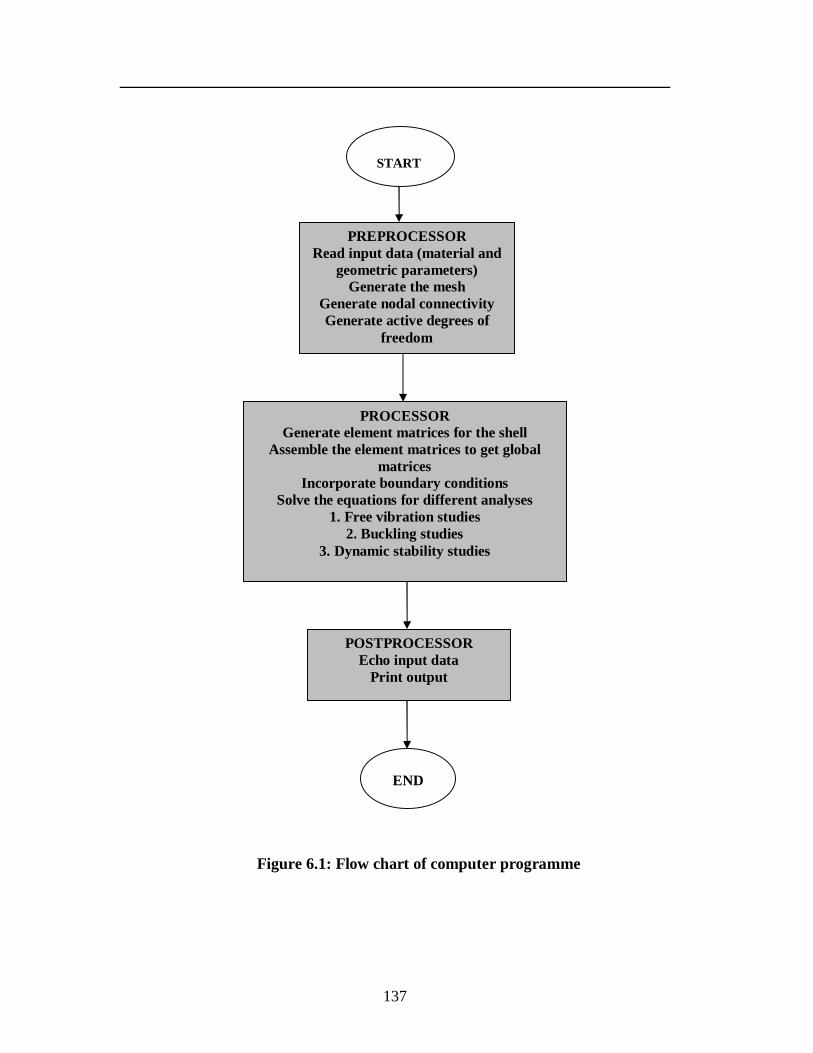
137
Figure 6.1: Flow chart of computer programme
START
PREPROCESSOR Read input data (material and
geometric parameters) Generate the mesh
Generate nodal connectivity Generate active degrees of
freedom
PROCESSOR Generate element matrices for the shell
Assemble the element matrices to get global matrices
Incorporate boundary conditions Solve the equations for different analyses
1. Free vibration studies 2. Buckling studies
3. Dynamic stability studies
POSTPROCESSOR Echo input data
Print output
END