The Virgo detector - LAPP
46
L. Rolland - GraSPA2014 - Annecy-le-Vieux 1 The Virgo detector The Virgo detector L. Rolland LAPP-Annecy GraSPA summer school
-
Upload
khangminh22 -
Category
Documents
-
view
0 -
download
0
Transcript of The Virgo detector - LAPP

L. Rolland GraSPA2014 AnnecyleVieux 1
The Virgo detectorThe Virgo detector
L. RollandLAPP-Annecy
GraSPA summer school
L. Rolland GraSPA2014 AnnecyleVieux 2
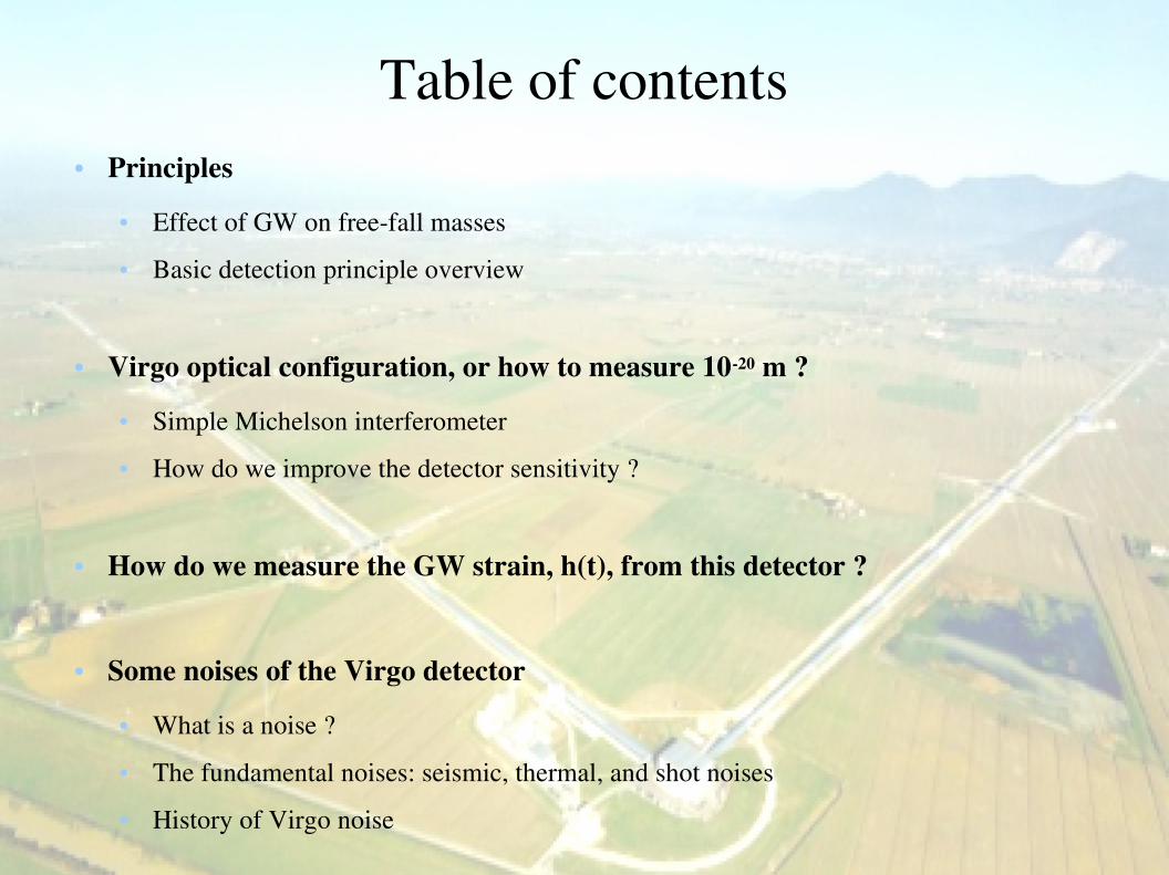
Table of contents● Principles
● Effect of GW on freefall masses
● Basic detection principle overview
● Virgo optical configuration, or how to measure 1020 m ?
● Simple Michelson interferometer
● How do we improve the detector sensitivity ?
● How do we measure the GW strain, h(t), from this detector ?
● Some noises of the Virgo detector
● What is a noise ?
● The fundamental noises: seismic, thermal, and shot noises
● History of Virgo noise

L. Rolland GraSPA2014 AnnecyleVieux 3
Reminder: effect of a GW on free masses
A gravitational wave (GW) modifies the distance between freefall masses
The Virgo detector – Principles
Case of a GW with polarization + propagating along z
(h has no dimension/unit)

L. Rolland GraSPA2014 AnnecyleVieux 4
A general overview of the Virgo detectorThe Virgo detector – Principles
Interferometer sketch

L. Rolland GraSPA2014 AnnecyleVieux 5
Virgo: a more complicated interferometer
L0
L0
Laser
Photodiodes
2
hLLx +=∆
2
hLLy −=∆
Suspended mirrors
Fabry-Perot cavities
Power-recycling cavity
Sensor: photodiode→ we do not image the interference pattern !Infra-red laser
P ~ 100 W
The Virgo detector – Principles
→ Mirrors can be considered as free for frequencies larger than ~10 Hz

L. Rolland GraSPA2014 AnnecyleVieux 7
Orders of magnitude
Input beam
Transmitted beam
The Virgo detector – Principles

L. Rolland GraSPA2014 AnnecyleVieux 8
How and for what did you use interferometers ?
Virgo interferometerPisa, Italy
Sodium doublet wavelength separation
Classroom interferometer
Wavelength of monochromatic source
The Virgo detector – Principles

L. Rolland GraSPA2014 AnnecyleVieux 9
Part 2: Virgo optical configuration
● Reminder about electromagnetic waves and planes waves
● How do we “observe” ∆L with a Michelson interferometer ?
● Measurement of a power variations
● From power variations to ∆L (or to gravitational wave amplitude h)
● Improving the interferometer:
● How do we increase the power on the beamsplitter mirror ?
● How do we amplify the phase offset between the arms ?
The Virgo detector – Optical configuration

L. Rolland GraSPA2014 AnnecyleVieux 10
Electromagnetic waves
● Propagation of a perturbation of electric and magnetic fields
● Direction of propagation: along k
● E and B are in phase, and with perpendicular directions
● E and B are perpendicular to the direction of propagation of the wave (transverse wave)
● Amplitude: amplitude of the E (or B) field,
● Two polarizations: defined by the direction of E (or B)
The Virgo detector – Optical configuration

L. Rolland GraSPA2014 AnnecyleVieux 11
Description of plane waves● Plane wave propagating along z, with speed c
● Average power:
amplitude
● Complex form
> simpler algebraic calculations, for example
> real plane wave is the real part:
● Plane waves do not exist but they are a good approximation of many waves in localized region of space
wave number (rad/m)
wavelength (m)
angular frequency (rad/s)
The Virgo detector – Optical configuration

L. Rolland GraSPA2014 AnnecyleVieux 12
How do we “observe” ∆L with a Michelson interferometer ?
● Input wave
● BS located at (0,0)
● Sensor located at (0,ys)
● Amplitude reflection and transmission coefficients: and
Input beam
Beamsplitter (BS)
Transmitted beam
→ We are interested in the beam transmitted by the interferometer: it is the sum of the two beams (fields) that have propagated along each arm.
x
y
Around the mirrors:
● Radius of curvature of the beam ~ 1400 m
● Size of the beam ~ few cm
→ The beam can be approximated by
plane waves
Sensor
The Virgo detector – Optical configuration

L. Rolland GraSPA2014 AnnecyleVieux 13
● Input wave
● Beam propagating along xarm: Input beam
Beamsplitter (BS)
x
y
Sign convention for amplitude reflection and transmission coefficients
How do we “observe” ∆L with a Michelson interferometer ?
Transmitted beam
Sensor
The Virgo detector – Optical configuration

L. Rolland GraSPA2014 AnnecyleVieux 14
● Input wave
● Beam propagating along xarm: Input beam
Beamsplitter (BS)
x
y
Sign convention for amplitude reflection and transmission coefficients
How do we “observe” ∆L with a Michelson interferometer ?
Transmitted beam
Sensor
The Virgo detector – Optical configuration

L. Rolland GraSPA2014 AnnecyleVieux 15
● Input wave
● Beam propagating along xarm: Input beam
Beamsplitter (BS)
x
y
Sign convention for amplitude reflection and transmission coefficients
How do we “observe” ∆L with a Michelson interferometer ?
Transmitted beam
Sensor
The Virgo detector – Optical configuration

L. Rolland GraSPA2014 AnnecyleVieux 16
● Input wave
● Beam propagating along xarm: Input beam
Beamsplitter (BS)
x
y
Complex reflection of the xarmSign convention for amplitude reflection and transmission coefficients
How do we “observe” ∆L with a Michelson interferometer ?
Transmitted beam
Sensor
The Virgo detector – Optical configuration

L. Rolland GraSPA2014 AnnecyleVieux 17
● Input wave
● Beam propagating along xarm:
● Beam propagating along yarm:
Input beam
Beamsplitter (BS)
x
y
Complex reflection of the xarm
Complex reflection of the yarm
How do we “observe” ∆L with a Michelson interferometer ?
Transmitted beam
Sensor
● Transmitted field:
+
The Virgo detector – Optical configuration

L. Rolland GraSPA2014 AnnecyleVieux 18
Power transmitted by a simple Michelson
With C=1
● Calculation of the transmitted power:
● Transmitted field:
With C=0.5
The Virgo detector – Optical configuration

L. Rolland GraSPA2014 AnnecyleVieux 19
What power does Virgo measure ?● In general, the beam is not a plane wave but a
spherical wave
→ interference pattern (and the complementary pattern in reflection)
● Virgo interference pattern much larger than the beam size: ~1 m between 2 two consecutive fringes
→ we do not study the fringes in nice images !
With C=1
Setting a working point
Freely swinging mirrors Controlled mirror positions
Equivalent size of Virgo beam
The Virgo detector – Optical configuration

L. Rolland GraSPA2014 AnnecyleVieux 20
From the power to the gravitational wave
● Around the working point:
● Power variations as function of small differential length variations:
The Virgo detector – Optical configuration

L. Rolland GraSPA2014 AnnecyleVieux 21
From the power to the gravitational wave
● Around the working point:
Measurable physical quantity
Physical effect to be detected
(W/m)
The Virgo detector – Optical configuration

L. Rolland GraSPA2014 AnnecyleVieux 22
Improving the interferometer sensitivity
BS
Increase the input power on BS
Recycling cavity
The Virgo detector – Optical configuration
Increase the phase difference between the arms for a given
differential arm length variation
Fabry-Perot cavities in the arms

L. Rolland GraSPA2014 AnnecyleVieux 27
Airy peaks
In Virgo, the beam is resonant inside the cavities
Virgo F = 50AdVirgo F = 443
Virgo cavity at resonance:
The Virgo detector – Optical configuration
Input beam
Reflected beam
Transmitted beam
Cavity beam
Average number of light roundtrips in the cavity:

L. Rolland GraSPA2014 AnnecyleVieux 28
(instead of in the arm of a simple Michelson)
Input beam
Transmitted beam
BS
Input beam
Transmitted beam
BS
~number of roundtrips in the arm~300 for AdVirgo
How do we amplify the phase offset ?
Sensor Sensor
3 km FabryPerot cavities
The Virgo detector – Optical configuration

L. Rolland GraSPA2014 AnnecyleVieux 29
How do we increase the power on BS ?
Resonant power recycling cavity
Input beam
Transmitted beam
BS
Detector working point close to a dark fringe → most of power go back towards the laser
→ input power on BS increased by a factor 38 !
Power recycling cavity
The Virgo detector – Optical configuration

L. Rolland GraSPA2014 AnnecyleVieux 30
The improved interferometer response
Input beam
Transmitted beam
BS
Sensor
Power recycling
cavity
3km FabryPerot cavities
(W/m)
● Response of simple Michelson:
● Response of recycled Michelson with FabryPerot cavities:
~38 ~300
The Virgo detector – Optical configuration

L. Rolland GraSPA2014 AnnecyleVieux 31
A hint of AdvancedVirgo sensitivity
Input beam
Transmitted beam
BS
Sensor
Power recycling
cavity
3km FabryPerot cavities
● Response of recycled Michelson with FabryPerot cavities:
In reality, the detector response depends on frequency...
The Virgo detector – Optical configuration

L. Rolland GraSPA2014 AnnecyleVieux 32
Optical layout of VirgoThe Virgo detector – Optical configuration

L. Rolland GraSPA2014 AnnecyleVieux 33
Part 3: How do we measure the GW strain, h(t), from this detector ?
● Notes about data processing
● Controlling the interferometer working point
● A glimpse on the calibration and h(t) reconstruction
● Data collection

L. Rolland GraSPA2014 AnnecyleVieux 34
Notes about data processing: digitizationThe Virgo detector – How do we measure the GW strain, h(t), from this detector ?
Analog signal s(t)
Digital signal s(n)
ContinuousA voltage in general
Discrete (sampling frequency)Can be stored numericallyCan be processed numerically
Warnings:Nyquist frequencyAliasing
ADC DAC

L. Rolland GraSPA2014 AnnecyleVieux 35
Notes about data processing: spectral analysisThe Virgo detector – How do we measure the GW strain, h(t), from this detector ?
Filtering the data = modifying the frequency components
(Discrete) Fourier transform
Inverse Fourier transform
Sine signal
~Dirac peak
Time (s) Frequency (Hz)
Sig
na
l s(n
)
Am
plit
ud
e A
(k) Random signal (“white noise”)
~flat distribution
Time (s)Frequency (Hz)
Sig
na
l s(n
)
Am
plit
ud
e A
(k)
Apply a low-pass filter on the signal
Time (s) Frequency (Hz)
Sig
na
l s(n
)
Am
plit
ud
e A
(k)

L. Rolland GraSPA2014 AnnecyleVieux 36
How do we control the working point ?
Input beam
Transmitted beam
Real-time digital calculations
We want to be (almost) fixed !Control loop done for noises with f between ~10 Hz and ~100 HzPrecision of the control ~ 10-16 m
Noises
The Virgo detector – How do we measure the GW strain, h(t), from this detector ?

L. Rolland GraSPA2014 AnnecyleVieux 37
From the detector data to the GW strain h(t)
attenuated by controls
as if no control,as if free falling
mirrors
+
(m/V)
Transmitted power
variations (W)
Control signals
(V)
(m/W)
Input signals Responses to be measured(calibrated) in dedicated
datasets
The Virgo detector – How do we measure the GW strain, h(t), from this detector ?

L. Rolland GraSPA2014 AnnecyleVieux 38
AdVirgo data acquisition summary
Photodiodes Currents in the mirror actuators
SeismometersMagnetometersThermometers
Cameras
GPS-synchronized digitizationSampling frequencies from 1 Hz to ~50 kHz
~2500 sensor signals to be digitized
Data acquisition processes (data formatting, timestamp, write to disks..)
~ 10000 channels
Continuous flow of ~2 TBytes/day (20 to 40 MBytes/s)Disk space on Virgo site: ~400 TB for 6 months of data
Longer storage: data sent via Ethernet to computing centers (Lyon, Bologna)
The Virgo detector – How do we measure the GW strain, h(t), from this detector ?
Sensors....

L. Rolland GraSPA2014 AnnecyleVieux 39
Part 4: Virgo noises

L. Rolland GraSPA2014 AnnecyleVieux 40
What is a noise in Virgo ?
● Stochastic (random) signal that contributes to the signal hrec
(t) but does not
contain information on the gravitational wave strain hGW
(t)
The Virgo detector – Noises
Extracted from Black Hole Hunter: http://www.blackholehunter.org/

L. Rolland GraSPA2014 AnnecyleVieux 41
How do we characterize a noise ?
The variations of the noise decrease when the data are averaged over longer time
Hypothesis: - we are looking for a constant signal S0 (=0.5) in the data
- data are noisy (Gaussian noise)
The mean value of the noise stays around 0The mean value of the signal stays around S
0.
Data points Distribution of the data
Time (s)
Time (s)
x(t)
(un
its)
x(t)
(un
its)
x(t)
(un
its)
Gaussian distribution:
x (units)
x (units)
x (units)
→ What is important to characterize a noise is it
dispersion σx !
Sampling period 0.1 s
L. Rolland GraSPA2014 AnnecyleVieux 42
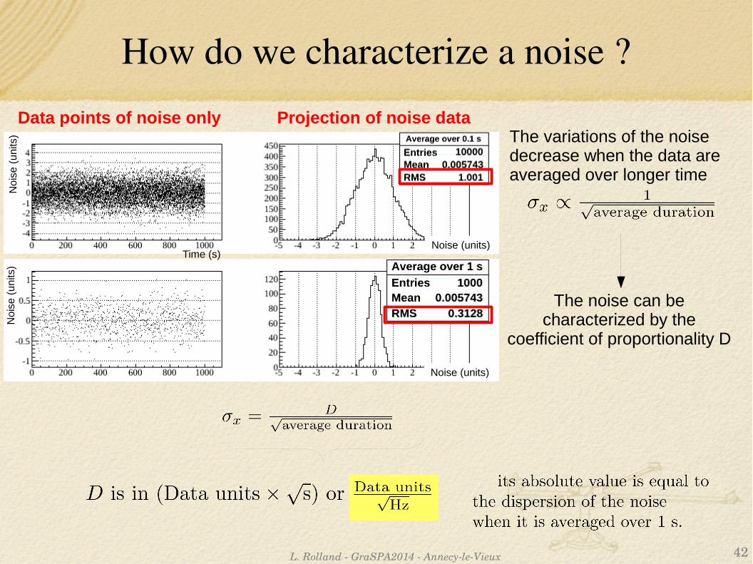
How do we characterize a noise ?
The variations of the noise decrease when the data are averaged over longer time
Data points of noise only Projection of noise data
Time (s)
Noi
se (
units
)N
oise
(u
nits
)
Noise (units)
Noise (units)
The noise can be characterized by the
coefficient of proportionality D

L. Rolland GraSPA2014 AnnecyleVieux 44
k
A(k
)
1 s
s(n)
How do we characterize a noise ...in frequencydomain ?
Discrete Fourier transform
Time (s) A(k) (units)
[A(k
)] (
t)
(un
its)

L. Rolland GraSPA2014 AnnecyleVieux 45
What is the noise level of Virgo ?
1 10 100 1000 1000010-23
10-22
10-21
10-20
10-19
10-18
(a) Virgo Nominal sensitivity (b) Seismic noise (c) Pendulum thermal noise (d) Mirror thermal noise (e) Shot Noise
h(f)
[1/s
qrt(H
z)]
Frequency [Hz]
(a)
(b)
(c)
(d)
(e)
The Virgo detector – Noises
Sum of all the noises

L. Rolland GraSPA2014 AnnecyleVieux 46
Seismic noise and suspended mirrors
Ground vibrations up to ~1 µm/√Hz at low frequency decreasing down to ~ 10 pm/√Hz at 100 Hz
The Virgo detector – Noises
Transfer function

L. Rolland GraSPA2014 AnnecyleVieux 47
Seismic noise and the Virgo suspension
● Passive attenuation: 7 pendulum in cascade
● Active controls at low frequency
● Accelerometers or interferometer data
● Electromagnetic actuators
● Control loops
7 m
The Virgo detector – Noises

L. Rolland GraSPA2014 AnnecyleVieux 48
Some noises: thermal noise
● Microscopic thermal fluctuations
> dissipation of energy through excitation of the macroscopic modes of the mirror
● We want high quality factors Q to concentrate all the noise in a small frequency band
Pendulum modef < 40 Hz
“Mirror” modef> few kHz
“Violin” modes f > 40 Hz
The Virgo detector – Noises

L. Rolland GraSPA2014 AnnecyleVieux 49
What is the shot noise ?
● Fluctuations of arrival times of photons (quantum noise)
The Virgo detector – Noises
Arrival time of single photons

L. Rolland GraSPA2014 AnnecyleVieux 50
Some other noises
● Acoustic vibrations and refraction index fluctuations
● Main elements installed in vacuum
● Laser: amplitude, frequency, jitter noise
● Lots of control loops to reduce these noises
● Electronics noise
● Challenge for the electronicians to measure down to 0.1 nW/sqrt(Hz)
● Nonlinear noise from diffuse light
● Need dedicated optical elements with specific mechanical modes
The Virgo detector – Noises

L. Rolland GraSPA2014 AnnecyleVieux 51
History of Virgo noise curve The Virgo detector – Noises

L. Rolland GraSPA2014 AnnecyleVieux 52
Noises are not always stationary...The Virgo detector – Noises
→ Now it is time to play with the data analysis !
“Glitches” are impulses of noise.They might look like a transient GW signal...