THE ULTIMATE TFM ULTRASONIC FLAW DETECTOR
7
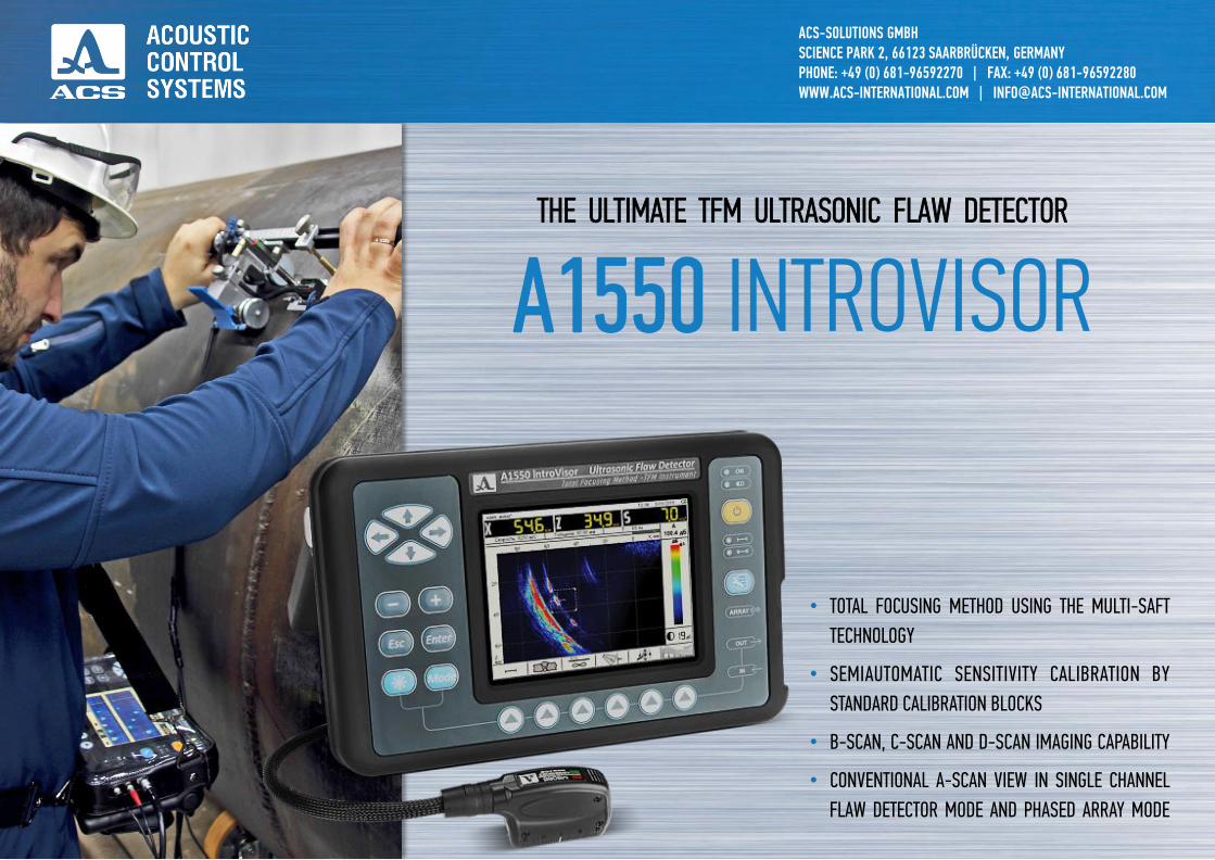
ACS-SOLUTIONS GMBH SCIENCE PARK 2, 66123 SAARBRÜCKEN, GERMANY PHONE: +49 (0) 681-96592270 | FAX: +49 (0) 681-96592280 WWW.ACS-INTERNATIONAL.COM | [email protected] • TOTAL FOCUSING METHOD USING THE MULTI-SAFT TECHNOLOGY • SEMIAUTOMATIC SENSITIVITY CALIBRATION BY STANDARD CALIBRATION BLOCKS • B-SCAN, C-SCAN AND D-SCAN IMAGING CAPABILITY • CONVENTIONAL A-SCAN VIEW IN SINGLE CHANNEL FLAW DETECTOR MODE AND PHASED ARRAY MODE THE ULTIMATE TFM ULTRASONIC FLAW DETECTOR A1550 INTROVISOR
-
Upload
khangminh22 -
Category
Documents
-
view
1 -
download
0
Transcript of THE ULTIMATE TFM ULTRASONIC FLAW DETECTOR
ACS-SOLUTIONS GMBHSCIENCE PARK 2, 66123 SAARBRÜCKEN, GERMANYPHONE: +49 (0) 681-96592270 | FAX: +49 (0) 681-96592280WWW.ACS-INTERNATIONAL.COM | [email protected]
• TOTAL FOCUSING METHOD USING THE MULTI-SAFT
TECHNOLOGY
• SEMIAUTOMATIC SENSITIVITY CALIBRATION BY
STANDARD CALIBRATION BLOCKS
• B-SCAN, C-SCAN AND D-SCAN IMAGING CAPABILITY
• CONVENTIONAL A-SCAN VIEW IN SINGLE CHANNEL
FLAW DETECTOR MODE AND PHASED ARRAY MODE
THE ULTIMATE TFM ULTRASONIC FLAW DETECTOR
A1550 INTROVISOR
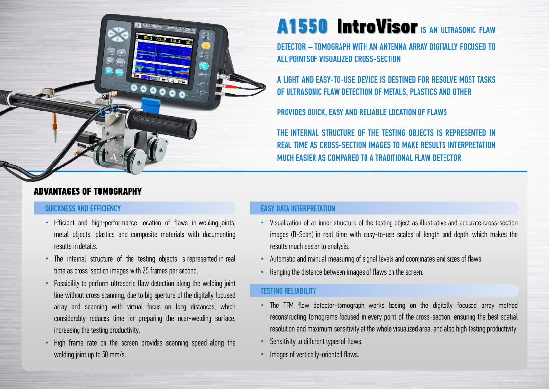
A1550 IntroVisor IS AN ULTRASONIC FLAW
DETECTOR – TOMOGRAPH WITH AN ANTENNA ARRAY DIGITALLY FOCUSED TO
ALL POINTSOF VISUALIZED CROSS-SECTION
A LIGHT AND EASY-TO-USE DEVICE IS DESTINED FOR RESOLVE MOST TASKS
OF ULTRASONIC FLAW DETECTION OF METALS, PLASTICS AND OTHER
PROVIDES QUICK, EASY AND RELIABLE LOCATION OF FLAWS
THE INTERNAL STRUCTURE OF THE TESTING OBJECTS IS REPRESENTED IN
REAL TIME AS CROSS-SECTION IMAGES TO MAKE RESULTS INTERPRETATION
MUCH EASIER AS COMPARED TO A TRADITIONAL FLAW DETECTOR
ADVANTAGES OF TOMOGRAPHY
QUICKNESS AND EFFICIENCY
• Efficient and high-performance location of flaws in welding joints,
metal objects, plastics and composite materials with documenting
results in details.
• The internal structure of the testing objects is represented in real
time as cross-section images with 25 frames per second.
• Possibility to perform ultrasonic flaw detection along the welding joint
line without cross scanning, due to big aperture of the digitally focused
array and scanning with virtual focus on long distances, which
considerably reduces time for preparing the near-welding surface,
increasing the testing productivity.
• High frame rate on the screen provides scanning speed along the
welding joint up to 50 mm/s.
EASY DATA INTERPRETATION
• Visualization of an inner structure of the testing object as illustrative and accurate cross-section
images (B-Scan) in real time with easy-to-use scales of length and depth, which makes the
results much easier to analysis.
• Automatic and manual measuring of signal levels and coordinates and sizes of flaws.
• Ranging the distance between images of flaws on the screen.
TESTING RELIABILITY
• The TFM flaw detector-tomograph works basing on the digitally focused array method
reconstructing tomograms focused in every point of the cross-section, ensuring the best spatial
resolution and maximum sensitivity at the whole visualized area, and also high testing productivity.
• Sensitivity to different types of flaws.
• Images of vertically-oriented flaws.
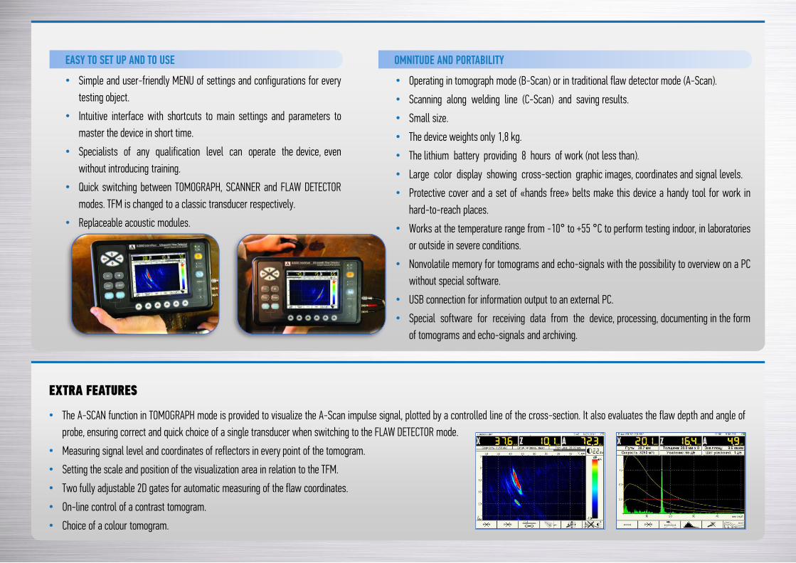
EASY TO SET UP AND TO USE
• Simple and user-friendly MENU of settings and configurations for every
testing object.
• Intuitive interface with shortcuts to main settings and parameters to
master the device in short time.
• Specialists of any qualification level can operate the device, even
without introducing training.
• Quick switching between TOMOGRAPH, SCANNER and FLAW DETECTOR
modes. TFM is changed to a classic transducer respectively.
• Replaceable acoustic modules.
OMNITUDE AND PORTABILITY
• Operating in tomograph mode (В-Scan) or in traditional flaw detector mode (А-Scan).
• Scanning along welding line (C-Scan) and saving results.
• Small size.
• The device weights only 1,8 kg.
• The lithium battery providing 8 hours of work (not less than).
• Large color display showing cross-section graphic images, coordinates and signal levels.
• Protective cover and a set of «hands free» belts make this device a handy tool for work in
hard-to-reach places.
• Works at the temperature range from -10° to +55 °С to perform testing indoor, in laboratories
or outside in severe conditions.
• Nonvolatile memory for tomograms and echo-signals with the possibility to overview on a PC
without special software.
• USB connection for information output to an external PC.
• Special software for receiving data from the device, processing, documenting in the form
of tomograms and echo-signals and archiving.
EXTRA FEATURES
• The A-SCAN function in TOMOGRAPH mode is provided to visualize the A-Scan impulse signal, plotted by a controlled line of the cross-section. It also evaluates the flaw depth and angle of
probe, ensuring correct and quick choice of a single transducer when switching to the FLAW DETECTOR mode.
• Measuring signal level and coordinates of reflectors in every point of the tomogram.
• Setting the scale and position of the visualization area in relation to the TFM.
• Two fully adjustable 2D gates for automatic measuring of the flaw coordinates.
• On-line control of а contrast tomogram.
• Choice of а colour tomogram.
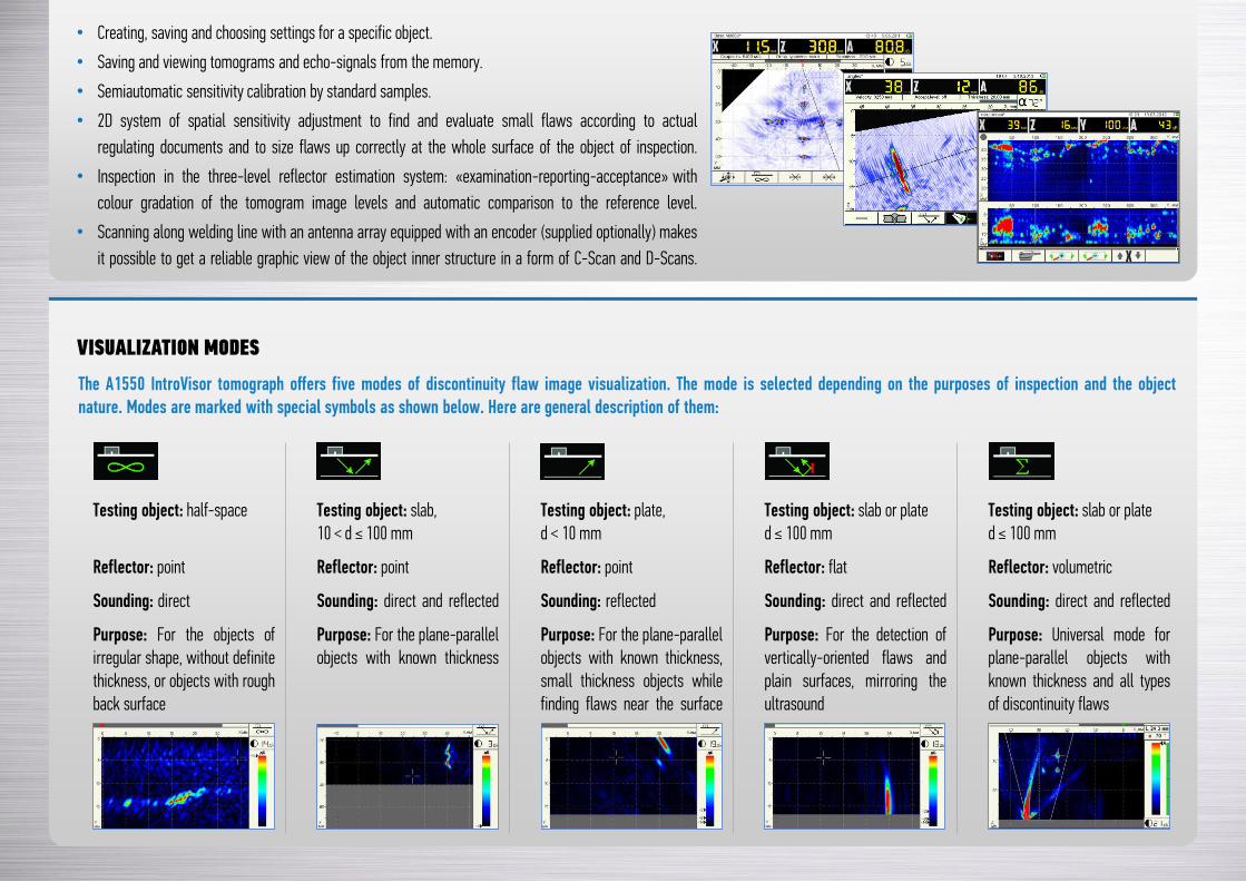
Testing object: half-space Testing object: slab,10 < d ≤ 100 mm
Testing object: plate,d < 10 mm
Testing object: slab or plated ≤ 100 mm
Testing object: slab or plated ≤ 100 mm
Reflector: point Reflector: point Reflector: point Reflector: flat Reflector: volumetric
Sounding: direct Sounding: direct and reflected Sounding: reflected Sounding: direct and reflected Sounding: direct and reflected
Purpose: For the objects ofirregular shape, without definitethickness, or objects with roughback surface
Purpose: For the plane-parallelobjects with known thickness
Purpose: For the plane-parallelobjects with known thickness,small thickness objects whilefinding flaws near the surface
Purpose: For the detection ofvertically-oriented flaws andplain surfaces, mirroring theultrasound
Purpose: Universal mode forplane-parallel objects withknown thickness and all typesof discontinuity flaws
VISUALIZATION MODES
The A1550 IntroVisor tomograph offers five modes of discontinuity flaw image visualization. The mode is selected depending on the purposes of inspection and the objectnature. Modes are marked with special symbols as shown below. Here are general description of them:
• Creating, saving and choosing settings for a specific object.
• Saving and viewing tomograms and echo-signals from the memory.
• Semiautomatic sensitivity calibration by standard samples.
• 2D system of spatial sensitivity adjustment to find and evaluate small flaws according to actual
regulating documents and to size flaws up correctly at the whole surface of the object of inspection.
• Inspection in the three-level reflector estimation system: «examination-reporting-acceptance» with
colour gradation of the tomogram image levels and automatic comparison to the reference level.
• Scanning along welding line with an antenna array equipped with an encoder (supplied optionally) makes
it possible to get a reliable graphic view of the object inner structure in a form of C-Scan and D-Scans.
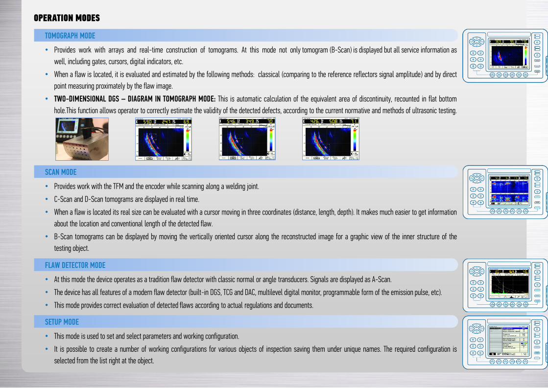
OPERATION MODES
TOMOGRAPH MODE
• Provides work with arrays and real-time construction of tomograms. At this mode not only tomogram (B-Scan) is displayed but all service information as
well, including gates, cursors, digital indicators, etc.
• When a flaw is located, it is evaluated and estimated by the following methods: classical (comparing to the reference reflectors signal amplitude) and by direct
point measuring proximately by the flaw image.
• TWO-DIMENSIONAL DGS – DIAGRAM IN TOMOGRAPH MODE: This is automatic calculation of the equivalent area of discontinuity, recounted in flat bottom
hole.This function allows operator to correctly estimate the validity of the detected defects, according to the current normative and methods of ultrasonic testing.
SCAN MODE
• Provides work with the TFM and the encoder while scanning along a welding joint.
• C-Scan and D-Scan tomograms are displayed in real time.
• When a flaw is located its real size can be evaluated with a cursor moving in three coordinates (distance, length, depth). It makes much easier to get information
about the location and conventional length of the detected flaw.
• B-Scan tomograms can be displayed by moving the vertically oriented cursor along the reconstructed image for a graphic view of the inner structure of the
testing object.
FLAW DETECTOR MODE
• At this mode the device operates as a tradition flaw detector with classic normal or angle transducers. Signals are displayed as A-Scan.
• The device has all features of a modern flaw detector (built-in DGS, TCG and DAC, multilevel digital monitor, programmable form of the emission pulse, etc).
• This mode provides correct evaluation of detected flaws according to actual regulations and documents.
SETUP MODE
• This mode is used to set and select parameters and working configuration.
• It is possible to create a number of working configurations for various objects of inspection saving them under unique names. The required configuration is
selected from the list right at the object.
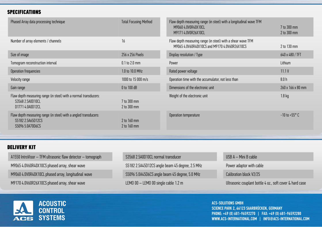
3D INTROVIEW® SOFTWARE
• Weld configuration wizard for common weld preparations.
• 2D-View modes: B, C & D-Scan / Cutting plane, gated volume.
• Synchronized 2D cursors for interactive flaw sizing.
• 3D-View modes: ISO-Surface Texture Mapping Maximum
Intensity Projection.
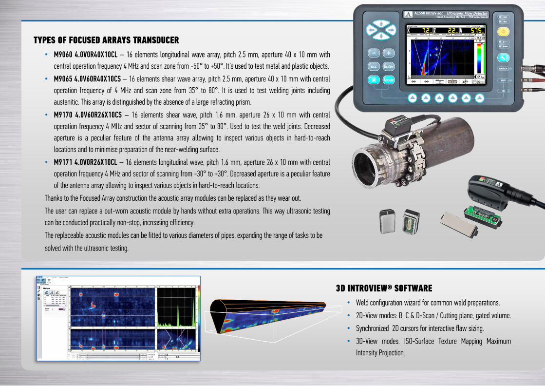
TYPES OF FOCUSED ARRAYS TRANSDUCER
• М9060 4.0V0R40X10CL – 16 elements longitudinal wave array, pitch 2.5 mm, aperture 40 x 10 mm with
central operation frequency 4 MHz and scan zone from -50° to +50°. It’s used to test metal and plastic objects.
• М9065 4.0V60R40X10CS – 16 elements shear wave array, pitch 2.5 mm, aperture 40 x 10 mm with central
operation frequency of 4 MHz and scan zone from 35° to 80°. It is used to test welding joints including
austenitic. This array is distinguished by the absence of a large refracting prism.
• M9170 4.0V60R26X10CS – 16 elements shear wave, pitch 1.6 mm, aperture 26 x 10 mm with central
operation frequency 4 MHz and sector of scanning from 35° to 80°. Used to test the weld joints. Decreased
aperture is a peculiar feature of the antenna array allowing to inspect various objects in hard-to-reach
locations and to minimise preparation of the near-welding surface.
• M9171 4.0V0R26X10CL – 16 elements longitudinal wave, pitch 1.6 mm, aperture 26 x 10 mm with central
operation frequency 4 MHz and sector of scanning from -30° to +30°. Decreased aperture is a peculiar feature
of the antenna array allowing to inspect various objects in hard-to-reach locations.
Thanks to the Focused Array construction the acoustic array modules can be replaced as they wear out.
The user can replace a out-worn acoustic module by hands without extra operations. This way ultrasonic testing
can be conducted practically non-stop, increasing efficiency.
The replaceable acoustic modules can be fitted to various diameters of pipes, expanding the range of tasks to be
solved with the ultrasonic testing.
ACS-SOLUTIONS GMBHSCIENCE PARK 2, 66123 SAARBRÜCKEN, GERMANYPHONE: +49 (0) 681-96592270 | FAX: +49 (0) 681-96592280WWW.ACS-INTERNATIONAL.COM | [email protected]
Phased Array data processing technique Total Focusing Method Flaw depth measuring range (in steel) with a longitudinal wave TFMМ9060 4.0V0R40X10CLМ9171 4.0V0R26X10CL
7 to 300 mm2 to 300 mm
Number of array elements / channels 16 Flaw depth measuring range (in steel) with a shear wave TFMM9065 4.0V60R40Х10CS and M9170 4.0V60R26X10CS 2 to 130 mm
Size of image 256 x 256 Pixels Display resolution / Type 640 x 480 / TFT
Tomogram reconstruction interval 0.1 to 2.0 mm Power Lithium
Operation frequencies 1.0 to 10.0 MHz Rated power voltage 11.1 V
Velocity range 1000 to 15 000 m/s Operation time with the accumulator, not less than 8.0 h
Gain range 0 to 100 dB Dimensions of the electronic unit 260 х 166 х 80 mm
Flaw depth measuring range (in steel) with a normal transducers:S3568 2.5A0D10CLD1771 4.0A0D12CL
7 to 300 mm2 to 300 mm
Weight of the electronic unit 1.8 kg
Flaw depth measuring range (in steel) with a angled transducers:S5182 2.5A65D12CSS5096 5.0A70D6CS
2 to 160 mm2 to 160 mm
Operation temperature -10 to +55° C
SPECIFICATIONS
А1550 IntroVisor – TFM ultrasonic flaw detector – tomograph S3568 2.5A0D10CL normal transducer USB A – Mini B cable
M9065 4.0V60R40Х10CS phased array, shear wave S5182 2.5А45D12CS angle beam 45 degree, 2.5 MHz Power adaptor with cable
М9060 4.0V0R40X10CL phased array, longitudinal wave S5096 5.0А45D6CS angle beam 45 degree, 5.0 MHz Calibration block V2/25
М9170 4.0V60R26X10CS phased array, shear wave LEMO 00 – LEMO 00 single cable 1.2 m Ultrasonic couplant bottle 4 oz., soft cover & hard case
DELIVERY KIT