Last stage control and mechanical transfer function measurement of the VIRGO suspensions
7
Last stage control and mechanical transfer function measurement of the VIRGO suspensions A. Bozzi, C. Bourgoin, S. Cortese, A. Errico, D. Enard, S. Mataguez, A. Paoli, A. Pasqualetti, P. Popolizio, F. Richard, J. M. Teuler, and Z. Zhang EGO, Traversa H di via Macerata, 56021, S. Stefano a Macerata (Pi), Italy C. Boccara, M. Leliboux, V. Loriette, V. Reita, and J. P. Roger ESPCI, 10 Rue Vauquelin, 75005 Paris, France P. Ganau, B. Lagrange, J. M. Mackowski, C. Michel, J. L. Montorio, N. Morgado, L. Pinard, and A. Remillieux IPNL, 43 Boulevard du 14 Novembre 1918, 69622 Villeurbanne Cedex, Lyon, France L. Bracci, G. Calamai, E. Cuoco, P. Dominici, L. Fabbroni, G. Guidi, G. Losurdo, F. Martelli, M. Mazzoni, M. Ripepe, R. Stanga, and F. Vetrano Istituto Nazionale di Fisica Nucleare, Sez. Firenze, Largo E. Fermi 2, 50125 Firenze, Italy F. Acernese, F. Barone, E. Calloni, S. Cavaliere, M. De Rosa, R. De Rosa, L. Di Fiore, a) A. Eleuteri, G. Evangelista, F. Garufi, M. Maiorino, L. Milano, K. Qipiani, S. Solimeno, and M. Varella Istituto Nazionale di Fisica Nucleare, sez. Napoli, and Dipartimento di Scienze Fisiche, University of Napoli ‘‘Federico II,’’Complesso Universitario di Monte S. Angelo, Via Cintia 80126 Napoli, Italy Dipartimento di Scienze Farmaceutiche, University of Salerno, Via Ponte Don Melillo, 84084 Fisciano (Sa) Italy P. Amico, C. Cattuto, L. Gammaitoni, F. Marchesoni, M. Punturo, and H. Vocca Istituto Nazionale di Fisica Nucleare, sez. Perugia and University of Perugia, Via A. Pascoli 06123, Perugia, Italy G. Ballardin, S. Braccini, C. Bradaschia, C. Casciano, R. Cavalieri, R. Cecchi, G. Cella, V. Dattilo, A. Di Virgilio, I. Ferrante, F. Fidecaro, F. Frasconi, G. Gennaro, A. Giazotto, L. Holloway, P. La Penna, T. Lomtadze, L. Nicolosi, F. Paoletti, R. Passaquieti, D. Passuello, R. Poggiani, R. Taddei, and A. Vicere Istituto Nazionale di Fisica Nucleare, Sez. Pisa, Via Livornese 1291, 56010 S. Piero A Grado (Pi), Italy S. Frasca, E. Majorana, C. Palomba, M. Perciballi, P. Puppo, P. Rapagnani, and F. Ricci Istituto Nazionale di Fisica Nucleare, Sez. Roma I, Piazzale Aldo Moro 5, 00185 Roma, Italy N. Arnaud, C. Arnault, M. Barsuglia, J. L. Beney, R. Bilhaut, M. A. Bizouard, V. Brisson, P. Canitrot, F. Cavalier, R. Chiche, S. Cuzon, M. Davier, M. Dehamme, C. Eder, M. Gaspard, P. Hello, P. Heusse, E. Jules, O. Lodygenski, B. Mansoux, J. C. Marrucho, M. Mencik, P. Marin, T. Pradier, A. Reboux, P. Rivoirard, and M. Taurigna Laboratoire de l’Accelerateur Lineaire, B.P. 34, 91898, Orsay, Fance F. Bellachia, D. Boget, D. Buskulic, B. Caron, F. Chollet, P. Y. David, D. Dufournaud, R. Flaminio, L. Fournier, L. Giacobone, C. Girard, R. Hermel, J. C. Lacotte, B. Lieunard, F. Marion, A. Masserot, L. Massonnet, B. Mours, P. Mugnier, J. Ramonet, R. Sottile, D. Verkindt, O. Veziant, and M. Yvert LAPP, Chemin de Bellevue, B.P 110, 74941, Annecy-le Vieux Cedex, France D. Babusci, H. Fang, G. Giordano, M. Iannarelli, and E. Turri INFN Laboratori Nazionali di Frascati, Via E. Fermi 40, 00044 Frascati (Roma), Italy F. Bondu, A. Brillet, J. Cachenaut, F. Cleva, T. Cokelaer, J. P. Coulon, J. D. Fournier, H. Heitmann, J. M. Innocent, M. Loupias, C. N. Man, J. Pacheco, T. Regimbau, J. P. Scheidecker, H. Trinquet, P. Tourrenc, and J. Y. Vinet Observatoire de la Cote d’Azur, B.P. 4229, 06034, Nice Cedex 4, France ~Received 2 November 2001; accepted for publication 10 December 2001! REVIEW OF SCIENTIFIC INSTRUMENTS VOLUME 73, NUMBER 5 MAY 2002 2143 0034-6748/2002/73(5)/2143/7/$19.00 © 2002 American Institute of Physics Downloaded 27 May 2002 to 141.108.12.125. Redistribution subject to AIP license or copyright, see http://ojps.aip.org/rsio/rsicr.jsp
-
Upload
independent -
Category
Documents
-
view
2 -
download
0
Transcript of Last stage control and mechanical transfer function measurement of the VIRGO suspensions
REVIEW OF SCIENTIFIC INSTRUMENTS VOLUME 73, NUMBER 5 MAY 2002
Last stage control and mechanical transfer function measurementof the VIRGO suspensions
A. Bozzi, C. Bourgoin, S. Cortese, A. Errico, D. Enard, S. Mataguez, A. Paoli,A. Pasqualetti, P. Popolizio, F. Richard, J. M. Teuler, and Z. ZhangEGO, Traversa H di via Macerata, 56021, S. Stefano a Macerata (Pi), Italy
C. Boccara, M. Leliboux, V. Loriette, V. Reita, and J. P. RogerESPCI, 10 Rue Vauquelin, 75005 Paris, France
P. Ganau, B. Lagrange, J. M. Mackowski, C. Michel, J. L. Montorio, N. Morgado,L. Pinard, and A. RemillieuxIPNL, 43 Boulevard du 14 Novembre 1918, 69622 Villeurbanne Cedex, Lyon, France
L. Bracci, G. Calamai, E. Cuoco, P. Dominici, L. Fabbroni, G. Guidi, G. Losurdo,F. Martelli, M. Mazzoni, M. Ripepe, R. Stanga, and F. VetranoIstituto Nazionale di Fisica Nucleare, Sez. Firenze, Largo E. Fermi 2, 50125 Firenze, Italy
F. Acernese, F. Barone, E. Calloni, S. Cavaliere, M. De Rosa, R. De Rosa, L. Di Fiore,a)
A. Eleuteri, G. Evangelista, F. Garufi, M. Maiorino, L. Milano, K. Qipiani, S. Solimeno,and M. VarellaIstituto Nazionale di Fisica Nucleare, sez. Napoli, and Dipartimento di Scienze Fisiche, University ofNapoli ‘‘Federico II,’’ Complesso Universitario di Monte S. Angelo, Via Cintia 80126 Napoli,Italy Dipartimento di Scienze Farmaceutiche, University of Salerno, Via Ponte Don Melillo, 84084Fisciano (Sa) Italy
P. Amico, C. Cattuto, L. Gammaitoni, F. Marchesoni, M. Punturo, and H. VoccaIstituto Nazionale di Fisica Nucleare, sez. Perugia and University of Perugia, Via A. Pascoli 06123,Perugia, Italy
G. Ballardin, S. Braccini, C. Bradaschia, C. Casciano, R. Cavalieri, R. Cecchi, G. Cella,V. Dattilo, A. Di Virgilio, I. Ferrante, F. Fidecaro, F. Frasconi, G. Gennaro,A. Giazotto, L. Holloway, P. La Penna, T. Lomtadze, L. Nicolosi, F. Paoletti,R. Passaquieti, D. Passuello, R. Poggiani, R. Taddei, and A. VicereIstituto Nazionale di Fisica Nucleare, Sez. Pisa, Via Livornese 1291, 56010 S. Piero A Grado (Pi), Italy
S. Frasca, E. Majorana, C. Palomba, M. Perciballi, P. Puppo, P. Rapagnani,and F. RicciIstituto Nazionale di Fisica Nucleare, Sez. Roma I, Piazzale Aldo Moro 5, 00185 Roma, Italy
N. Arnaud, C. Arnault, M. Barsuglia, J. L. Beney, R. Bilhaut, M. A. Bizouard, V. Brisson,P. Canitrot, F. Cavalier, R. Chiche, S. Cuzon, M. Davier, M. Dehamme, C. Eder,M. Gaspard, P. Hello, P. Heusse, E. Jules, O. Lodygenski, B. Mansoux, J. C. Marrucho,M. Mencik, P. Marin, T. Pradier, A. Reboux, P. Rivoirard, and M. TaurignaLaboratoire de l’Accelerateur Lineaire, B.P. 34, 91898, Orsay, Fance
F. Bellachia, D. Boget, D. Buskulic, B. Caron, F. Chollet, P. Y. David, D. Dufournaud,R. Flaminio, L. Fournier, L. Giacobone, C. Girard, R. Hermel, J. C. Lacotte,B. Lieunard, F. Marion, A. Masserot, L. Massonnet, B. Mours, P. Mugnier, J. Ramonet,R. Sottile, D. Verkindt, O. Veziant, and M. YvertLAPP, Chemin de Bellevue, B.P 110, 74941, Annecy-le Vieux Cedex, France
D. Babusci, H. Fang, G. Giordano, M. Iannarelli, and E. TurriINFN Laboratori Nazionali di Frascati, Via E. Fermi 40, 00044 Frascati (Roma), Italy
F. Bondu, A. Brillet, J. Cachenaut, F. Cleva, T. Cokelaer, J. P. Coulon, J. D. Fournier,H. Heitmann, J. M. Innocent, M. Loupias, C. N. Man, J. Pacheco, T. Regimbau,J. P. Scheidecker, H. Trinquet, P. Tourrenc, and J. Y. VinetObservatoire de la Cote d’Azur, B.P. 4229, 06034, Nice Cedex 4, France
~Received 2 November 2001; accepted for publication 10 December 2001!
21430034-6748/2002/73(5)/2143/7/$19.00 © 2002 American Institute of Physics
Downloaded 27 May 2002 to 141.108.12.125. Redistribution subject to AIP license or copyright, see http://ojps.aip.org/rsio/rsicr.jsp
Paola Puppo
[13]

2144 Rev. Sci. Instrum., Vol. 73, No. 5, May 2002 Bozzi et al.
The automatic control of the suspended mirrors is a major task in operating an interferometricgravitational wave antenna. To reach the extreme sensitivity required for this kind of detector, anaccurate alignment and a stable locking of the interferometer on its working point are crucial. Thesolution of this problem is particularly complex in the case of a multistage pendulum, such as thesuspension system for seismic isolation adopted in VIRGO. A precise knowledge of the suspensionmechanical transfer functions~TFs! for different forces applied in the control servo-loops representsessential information to reach the goal. In this article, we describe the apparatus we developed tomeasure the VIRGO suspension TF and we report the results thus obtained on full-scale suspensionsat the VIRGO site. Preliminary results for the implemented control system of the last suspensionstage are also presented. ©2002 American Institute of Physics.@DOI: 10.1063/1.1463717#
n-o
thlte
aisoeno-on-illao
onr
m
astinessuth
u
pnlle
dSAec
e
.ap-at-
ting
sthem-the
di-thernd
geedi-d a
theted-ndA
rderinth ae-e-o ofus-of
d toithent
ted
re-thederh a
assow.
ma
I. INTRODUCTION
Ground based interferomeric gravitational wave~GW!detectors1 are long base line Michelson interferometers~MIs!whose arms host long Fabry–Perot~FP! cavities or opticaldelay lines. The typical arm length ranges from a few hudred meters2,3 to a few km.4,5 To reach the extreme sensitivity required for GW detection, all the optical componentssuch a detector must be carefully isolated from allsources of external disturbance. In particular, in order to figround vibrations, the mirrors are suspended to seismictenuators, which are essentially pendula, for horizontallation, but with an adequate elastic internal structure for vtical isolation. Such an attenuator gives a good attenuatioseismic oscillations at frequencies above its pendulum nmal modes~NMs!, the drawback being that, at the NM frequencies, the mirrors can undergo rather large oscillati~up to several hundred microns!. For this reason, an automatic control system is necessary to damp the NM osctions and to control the relative orientation and positionthe mirrors in order to align the interferometer and lock itthe working point~dark fringe for the MI and resonance fothe FP cavities!. The error signals for the servomechaniswhich operates on many degrees of freedom~DOF! are pro-vided by the interferometer itself and by additional locmeasurement systems~position sensors, accelerometer!.The actuators are generally coil/magnet pairs; by regulathe current flowing in the coils it is possible to exert forcon magnets that are placed at different positions on thepension and then to induce translations or rotations tosuspended optical components@mirrors, beam splitter~BS!,etc.#.
For the VIRGO interferometer, the suspension is a mtistage seismic isolator, called superattenuator~SA!, made ofa preisolation stage~an inverted pendulum supporting the tostage of the suspension!, a cascade of five passive isolatiostages, and a lower part with a steering element, ca‘‘marionetta,’’ to which the test mass of the suspension~thatis one of the optical elements of the interferometer! and arecoil mass, called ‘‘reference mass,’’ are suspended. Atailed description of the SA can be found in Ref. 6. Thepermits to extend the VIRGO frequency band for GW dettion down to about 4 Hz; the price to pay is the extrem
a!Author to whom correspondence should be addressed; [email protected]
Downloaded 27 May 2002 to 141.108.12.125. Redistribution subject to
-
fert--
r-ofr-
s
-f
,
l
g
s-e
l-
d
e-
-
complexity of the mechanical behavior of the suspensionTo control the test mass movement, forces can be
plied on the SA at various levels. There are three coils,tached to the external structure surrounding the SA, acon the top stage~used for inertial damping7 and dc control!.Four coils~two horizontal and two vertical! are mounted onlegs attached to the last passive filter~called ‘‘filter 7’’ forhistorical reasons! and act on four magnets glued to the armof the marionetta; these coils allow to apply a force onmarionetta center of mass in the direction of the interferoeter optical axis and torques around axes orthogonal to~interferometer! optical axis. Four more~horizontal! coils areattached to the reference mass acting on four magnetsrectly attached to the back surface of the test mass. Furinformation on the actuators acting on the SA can be fouin Ref. 8.
In order to design the complex servo-loops9,10 requiredto control the SA of the VIRGO antenna, accurate knowledof the mechanical TF is necessary; to this purpose, a dcated interferometric device was designed which allowenoncontact TF measurement by sending a laser beam onsurface of the optical element and looking at the reflecbeam. In a previous article,11 we describe in detail the motivation and the principles of operation of such a device areport on preliminary testing performed on a prototype.new version of the earlier device has been designed in oto measure the TF of the final SA at the VIRGO siteCascina, based on the same principle of operation but wicompletely different optical layout, compatible with the dtector geometry. In this article we describe in detail this dvice and report the actual measurements performed on twthe VIRGO suspensions. In particular they are the BS spension and the one of the input mirrors of the west armthe interferometer WI. The measured TFs have been usedesign the servo-loops to control the mirror position wrespect to a local reference provided by the measuremdevice itself; preliminary results are reported in a dedicasection.
II. INSTRUMENT DESCRIPTION
In Fig. 1, we show the schematic setup for TF measument. A laser beam is sent through an optical window tosurface of the optical component that is suspended unvacuum. The reflected beam exits the vacuum tank througsecond window, is reflected by a mirror back to the test msurface, and then is further reflected to the entrance windil:
AIP license or copyright, see http://ojps.aip.org/rsio/rsicr.jsp

ur-e
ne
e
erb
ea
nd
eratly
to fitm
osi-cal
of
htsrstut
heof
ade-
n.me-
n
n
2145Rev. Sci. Instrum., Vol. 73, No. 5, May 2002 VIRGO suspension control
The movement of the suspended mirror can be measby looking at the reflected beam~assuming that the displacements of the test mass are larger that those of the otherments of the apparatus!. In particular, we are interested ithree DOF of the suspended mirror, namely the displacemZ along the optical axis~orthogonal to the mirror surface!and the rotations~ux anduy! around axes orthogonal to thoptical axis~pitch and yaw, respectively!.
The displacementZ is measured by a Mach–Zehndinterferometer; one of the two arms is the beam reflectedthe suspended mirror, while the other~reference arm! isfolded several times on a rigid platform. The angular msurement is provided by a position sensing device~PSD!illuminated by a small fraction of the reflected beam amounted on the same rigid platform.
In Fig. 2 we sketched the optical setup. The main diffence with respect to the setup described in Ref. 11 is thlarge part of the optical path is in fiber optics. This is main
FIG. 1. Schematic setup for TF measurement.
FIG. 2. Optical scheme for TF measurement. FBS5fiber beam splitter,C5fiber output coupler, l/25half-wave plate, P5polarizer, PZT5piezoelectric fiber stretcher, BS5beam splitter,L1515 cm focal lengthlens, BS1 beam sampler, PD photodiode,L2510 cm focal length lens,PSD5position sensing device, TM5piezoelectric tilting mirror.
Downloaded 27 May 2002 to 141.108.12.125. Redistribution subject to
ed
le-
nt
y
-
-a
necessary to reduce the overall size of the detector so asthe limited space available around the VIRGO vacuuchambers. A second important point is that, due to the ption of the optical windows on the vacuum tanks, the optibeam plane is not horizontal, but its normal is at an angleabout 23° with the normal~Fig. 1!.
The light source is a single-mode He–Ne laser that ligthe device through a single mode optical fiber. On the fiplatform there is a fiber beam splitter FBS that is the inpBS of the Mach–Zehnder interferometer. At the exit of tFBS, one of the two fiber arms, that is, the reference armthe interferometer, is folded several times on a home-mpiezoelectric fiber stretcher~PZT! which is used as an actuator to control the optical path length~OPL! and then to holdthe interferometer locked on the fringe, and for calibratioAt the end of the fiber there is an output coupler and sopolarization control optics~a half-wave plate and a polariz
FIG. 3. BS suspension;uy ~yaw! transfer function for a torque applied othe marionetta with the two horizontal coils of the filter 7~points! comparedwith an analytical curve fitted to the data~solid line!.
FIG. 4. BS suspension;ux ~pitch! transfer function for a torque applied othe marionetta with the two vertical coils of the filter 7~points! comparedwith an analytical curve fitted to the data~solid line!.
AIP license or copyright, see http://ojps.aip.org/rsio/rsicr.jsp
thouaasa
Oerrat
thi
t
t ofn ar ishe
ZTer-to
o
ad-
weoutis-
i-
ishe
e
e
i-
2146 Rev. Sci. Instrum., Vol. 73, No. 5, May 2002 Bozzi et al.
ing BS!. At the fiber exit, the reference beam goes tooutput ~bulk! BS of the interferometer and is split onto twphotodiodes. The second exit arm of the FBS is the measment arm. The beam leaves the fiber through a couplerpolarization control optics and is directed to the test mthrough the input window. After the output window there issecond platform supporting a mirror, mounted on a two DPZT tilting mount, that is used for fine alignment of thinterferometer. The reflected beam goes back to the misurface and to the input platform where it is split in two bybeam sampler. The large part of the beam is directed tooutput BS of the Mach–Zehnder, where it interferes withlight of the reference arm; the interference fringe patterndetected by two output photodiodes~PDs!. The difference ofthe two PD signals gives a measure of the changes in
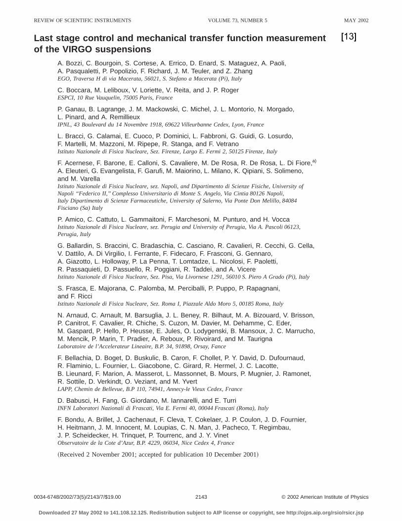
FIG. 5. BS suspension;Z transfer function for a force applied on the maronetta with the two horizontal coils of the filter 7~points! compared with ananalytical curve fitted to the data~solid line!. In this case the measurementvery noisy below 400 Hz and the only information in low frequency is tposition of the mode at 292 mHz.
FIG. 6. WI suspension;uy transfer function for a torque applied on thmarionetta with the two horizontal coils of the filter 7~points! comparedwith an analytical curve fitted to the data~solid line!.
Downloaded 27 May 2002 to 141.108.12.125. Redistribution subject to
e
re-nds
F
or
hees
he
OPL, which in turns depends on the relative displacementhe measurement device and the VIRGO mirror. To obtaisignal proportional to the displacement, the interferometelocked on the slope of the fringe using the PZT actuator. Tactuating signal, that is the signal at the input of the Pdriver, is then proportional to the changes in the OPL diffence~provided that the PZT transfer function is flat upabout 100 Hz!.
Besides the possibility of making the OPL of the twinterferometer arms almost equal~within a few cm, while themeasurement arm is more than 6 m long! without increasingthe size of the device, the use of fiber optics gives thevantage that the longitudinal actuator~fiber stretcher! is com-pletely decoupled from rotations of the beam, and thencan change the OPL difference by a large amount withaffecting the alignment of the interferometer. The main d
FIG. 7. WI suspension;ux transfer function for a torque applied on thmarionetta with the two vertical coils of the filter 7~points! compared withan analytical curve fitted to the data~solid line!.
FIG. 8. WI suspensionZ transfer function for a force applied on the maronetta with the two horizontal coils of the filter 7~points! compared with ananalytical curve fitted to the data~solid line!.
AIP license or copyright, see http://ojps.aip.org/rsio/rsicr.jsp
l
2147Rev. Sci. Instrum., Vol. 73, No. 5, May 2002 VIRGO suspension control
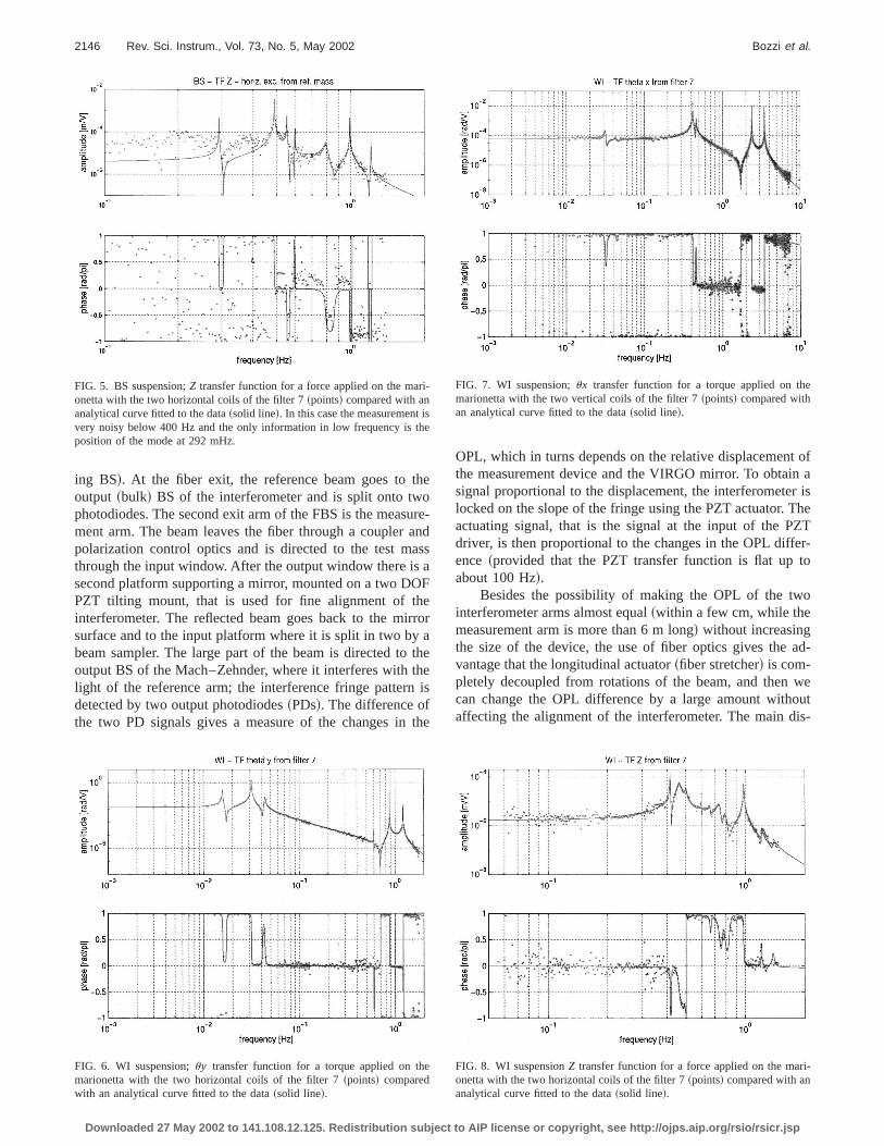
FIG. 9. WI suspension;Z transfer function for a forceapplied on the mirror with two coils~U and D! of thereference mass~points! compared with an analyticacurve fitted to the data~solid line!.
-
o-ath
t.
elyiocuc
ee
f ti
usrs
thu
ter-
ri-
ing
ults
;
ich
istemodna-
pro-les
advantage is that the long fiber~about 4.5 m! becomes sensitive to thermal drifts and acoustic noise.
A smaller fraction of the beam goes on a twdimensional PSD placed in the focus of a lens; in this wthe position of the spot on the sensor only depends onincidence angle and is almost insensitive~as far as the thinlens approximation holds! to transverse beam displacemen
III. TRANSFER FUNCTION MEASUREMENTS
The measurement of the transfer functions is performwith the device described in the previous section, by apping a known signal to the actuators placed on the suspensand used for the automatic alignment and locking. In partilar we are interested in measuring the displacements induwith the four coils attached to the filter 7 legs6,8 and actingon the marionetta, and with the four coils placed on the rerence mass and acting directly on the mirror. At a givfrequency, the TF can be measured if the displacement omirror induced by the actuators is larger than those the mror and the measurement device undergo for other ca~mainly seismic noise!. Generally we use pairs of actuato~with signals in phase or in counterphase! in order to apply apure torque or a pure force on the center of mass ofmirror; the cross terms of the TF provide information abothe symmetry of the system.
TABLE I. BS suspension; parameters used for the analyticaluy TF shownin Fig. 3; the dc gain is 1022 rad/V.
Poles Zeroes
Freq.~Hz! Q Freq.~Hz! Q
0.014 100 0.015 1000.031 200 0.039 50
0.041 3 50 0.6536 .103
0.843 75 .104
1.193 75 .104
Downloaded 27 May 2002 to 141.108.12.125. Redistribution subject to
ye
d,-ns-ed
f-nher-es
et
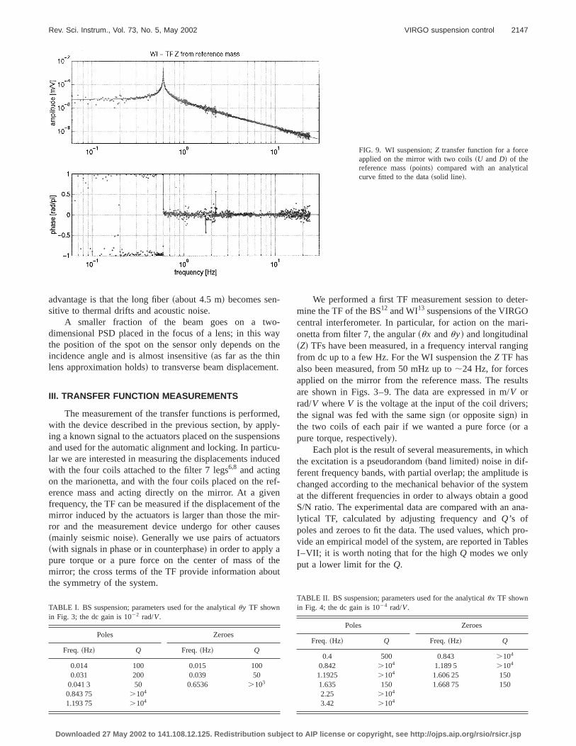
We performed a first TF measurement session to demine the TF of the BS12 and WI13 suspensions of the VIRGOcentral interferometer. In particular, for action on the maonetta from filter 7, the angular~ux anduy! and longitudinal~Z! TFs have been measured, in a frequency interval rangfrom dc up to a few Hz. For the WI suspension theZ TF hasalso been measured, from 50 mHz up to;24 Hz, for forcesapplied on the mirror from the reference mass. The resare shown in Figs. 3–9. The data are expressed in m/V orrad/V whereV is the voltage at the input of the coil driversthe signal was fed with the same sign~or opposite sign! inthe two coils of each pair if we wanted a pure force~or apure torque, respectively!.
Each plot is the result of several measurements, in whthe excitation is a pseudorandom~band limited! noise in dif-ferent frequency bands, with partial overlap; the amplitudechanged according to the mechanical behavior of the sysat the different frequencies in order to always obtain a goS/N ratio. The experimental data are compared with an alytical TF, calculated by adjusting frequency andQ’s ofpoles and zeroes to fit the data. The used values, whichvide an empirical model of the system, are reported in TabI–VII; it is worth noting that for the highQ modes we onlyput a lower limit for theQ.
TABLE II. BS suspension; parameters used for the analyticalux TF shownin Fig. 4; the dc gain is 1024 rad/V.
Poles Zeroes
Freq.~Hz! Q Freq.~Hz! Q
0.4 500 0.843 .104
0.842 .104 1.189 5 .104
1.1925 .104 1.606 25 1501.635 150 1.668 75 1502.25 .104
3.42 .104
AIP license or copyright, see http://ojps.aip.org/rsio/rsicr.jsp
avseric
foerB
alh
threpthd
th
l
n
tee
heom
Hzsl
5.6
2148 Rev. Sci. Instrum., Vol. 73, No. 5, May 2002 Bozzi et al.
IV. PAYLOAD CONTROL
As explained above, the main motivation for TF mesurement, is the characterization of the mechanical behaof the suspension for forces applied with the actuators ufor automatic alignment and locking of the interferometantenna.
To check that the measurements provide the right inmation, the measured TFs have been used to design sloops that control the position of the test masses, bothand WI in the three relevant DOF, by using, as error signthose provided by the TF measurement device itself. Tresults where satisfactory; in particular we were able forfirst time to control the suspension simultaneously withspect to all the three DOF with stable and robust servo-looThe angular servo-loops were essentially devoted todamping of the normal modes plus the control of theorientation of the mirrors~by the use of an integrator!; thecontrol was performed acting on the marionetta throughcoils on filter 7.
For the longitudinal control~Z!, we tested both a normamode damping acting on the marionetta from filter 7~BSsuspension! and a servo-loop with a larger BW by acting othe mirror from the reference mass~WI suspension!. Thevoltage at the PZT used to control the Mach–Zehnder inferometer of the TF measurement device provided the msurement of the mirror displacement.
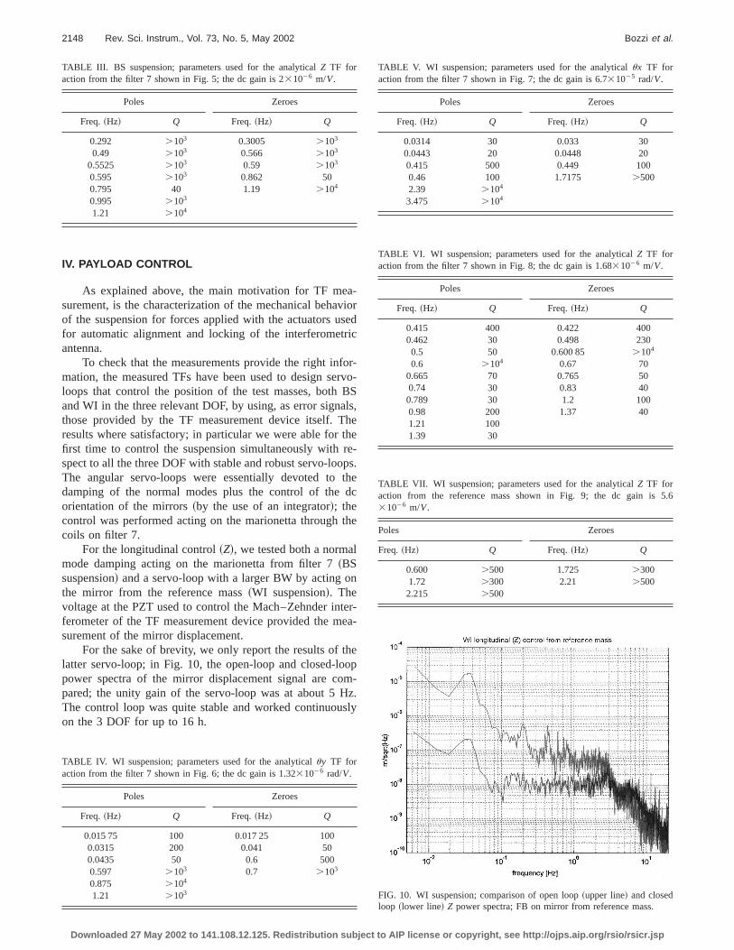
For the sake of brevity, we only report the results of tlatter servo-loop; in Fig. 10, the open-loop and closed-lopower spectra of the mirror displacement signal are copared; the unity gain of the servo-loop was at about 5The control loop was quite stable and worked continuouon the 3 DOF for up to 16 h.
TABLE III. BS suspension; parameters used for the analyticalZ TF foraction from the filter 7 shown in Fig. 5; the dc gain is 231026 m/V.
Poles Zeroes
Freq.~Hz! Q Freq.~Hz! Q
0.292 .103 0.3005 .103
0.49 .103 0.566 .103
0.5525 .103 0.59 .103
0.595 .103 0.862 500.795 40 1.19 .104
0.995 .103
1.21 .104
TABLE IV. WI suspension; parameters used for the analyticaluy TF foraction from the filter 7 shown in Fig. 6; the dc gain is 1.3231026 rad/V.
Poles Zeroes
Freq.~Hz! Q Freq.~Hz! Q
0.015 75 100 0.017 25 1000.0315 200 0.041 500.0435 50 0.6 5000.597 .103 0.7 .103
0.875 .104
1.21 .103
Downloaded 27 May 2002 to 141.108.12.125. Redistribution subject to
-iord
r-vo-Ss,ee-s.e
c
e
r-a-
p-.y
FIG. 10. WI suspension; comparison of open loop~upper line! and closedloop ~lower line! Z power spectra; FB on mirror from reference mass.
TABLE V. WI suspension; parameters used for the analyticalux TF foraction from the filter 7 shown in Fig. 7; the dc gain is 6.731025 rad/V.
Poles Zeroes
Freq.~Hz! Q Freq.~Hz! Q
0.0314 30 0.033 300.0443 20 0.0448 200.415 500 0.449 1000.46 100 1.7175 .5002.39 .104
3.475 .104
TABLE VI. WI suspension; parameters used for the analyticalZ TF foraction from the filter 7 shown in Fig. 8; the dc gain is 1.6831026 m/V.
Poles Zeroes
Freq.~Hz! Q Freq.~Hz! Q
0.415 400 0.422 4000.462 30 0.498 2300.5 50 0.600 85 .104
0.6 .104 0.67 700.665 70 0.765 500.74 30 0.83 400.789 30 1.2 1000.98 200 1.37 401.21 1001.39 30
TABLE VII. WI suspension; parameters used for the analyticalZ TF foraction from the reference mass shown in Fig. 9; the dc gain is31026 m/V.
Poles Zeroes
Freq.~Hz! Q Freq.~Hz! Q
0.600 .500 1.725 .3001.72 .300 2.21 .5002.215 .500
AIP license or copyright, see http://ojps.aip.org/rsio/rsicr.jsp
aatwltfa
foraoo
sphesahe
wthaseithle
, B..l-
. R.
e
e
al
2149Rev. Sci. Instrum., Vol. 73, No. 5, May 2002 VIRGO suspension control
V. DISCUSSION
In this article we described the device used for the chacterization of the last stages of the VIRGO suspensionsreport the results of the measurements performed onon-site suspensions in Cascina. It seems that the generasponse of the suspensions is in close agreement withdesign specifications. Next, we designed the servo-loopsthe ~local! control of the test mass on three DOF; this isfirst step toward the design of the complex servo-loopsthe control of the whole antenna. The results are encouing, since we have shown for the first time the feasibilitythe position control of the VIRGO test masses by meansforces internal to the suspension itself only~of course withthe exception of dc control, below;50 mHz, that will beperformed on the top stage!. The device described in thiarticle permits to obtain useful information for servo-loodesign and simulation fine tuning and will be used for tcharacterization of the other suspensions when necesThe sensitivity of the measurement is mainly limited by tseismic noise acting on the device itself~this limits the mea-surement band for forces applied on the marionetta belofew Hz!; a substantial improvement can be achieved byuse of vibration isolation platforms for supporting the opticelements of the device. The design already allows the intion of commercial three-dimensional seismic isolators wresonance frequency around 500 mHz; this will be impmented, if necessary, for the next measurements.
Downloaded 27 May 2002 to 141.108.12.125. Redistribution subject to
r-ndore-heor
rg-ff
ry.
aelr-
-
ACKNOWLEDGMENTS
The authors are grateful to our technicians F. CasseseD’Acquino, M. Di Pietro, M. Favati, G. Pontoriere, RRocco, and F. Vignoli for their skillful assistance in the reaization and setting up of the device. One of us~L.D.F.! wantsto dedicate this work to the memory of Renato Gorini.
1For a review about interferometric GW detection see, for example, PSaulson,Interferometric Gravitational Wave Detectors~World Scientific,Singapore, 1994!.
2K. Danzmann inFirst Eduardo Amaldi Conference on Gravitational WavExperiments, edited by E. Coccia, G. Pizzella, and F. Ronga~World Sci-entific, Singapore, 1995!.
3K. Tsubono, inFirst Eduardo Amaldi Conference on Gravitational WavExperiments, edited by E. Coccia, G. Pizzella, and F. Ronga~World Sci-entific, Singapore, 1995!.
4B. Caronet al., Class. Quantum Grav.14, 1461~1997!.5P. Fritschel, inSecond Eduardo Amaldi Conference on GravitationWaves, edited by E. Coccia, G. Pizzella, and G. Veneziano~World Scien-tific, Singapore, 1997!.
6G. Ballardinet al., Rev. Sci. Instrum.72, 3643~2001!.7G. Losurdoet al., Rev. Sci. Instrum.72, 3653~2001!.8A. Bernardiniet al., Rev. Sci. Instrum.70, 3463~1999!.9B. Caronet al., Astropart. Phys.6, 245 ~1997!.
10M. Barsugliaet al., VIR-NOT-NAP-1390-143, 2000.11E. Calloniet al., Rev. Sci. Instrum.69, 1882~1998!.12V. Calbucciet al., VIR-NOT-NAP-1390-173, 2001.13V. Calbucciet al., VIR-NOT-NAP-1390-174, 2001.
AIP license or copyright, see http://ojps.aip.org/rsio/rsicr.jsp