The Local Buckling Strength of Partially Stiffened Type 3CR12 ...
13
Missouri University of Science and Technology Missouri University of Science and Technology Scholars' Mine Scholars' Mine International Specialty Conference on Cold- Formed Steel Structures (1998) - 14th International Specialty Conference on Cold-Formed Steel Structures Oct 15th, 12:00 AM The Local Buckling Strength of Partially Stiffened Type 3CR12 The Local Buckling Strength of Partially Stiffened Type 3CR12 Stainless Steel Compression Elements in Beam Flanges Stainless Steel Compression Elements in Beam Flanges G. J. van den Berg Follow this and additional works at: https://scholarsmine.mst.edu/isccss Part of the Structural Engineering Commons Recommended Citation Recommended Citation van den Berg, G. J., "The Local Buckling Strength of Partially Stiffened Type 3CR12 Stainless Steel Compression Elements in Beam Flanges" (1998). International Specialty Conference on Cold-Formed Steel Structures. 4. https://scholarsmine.mst.edu/isccss/14iccfsss/14iccfsss-session11/4 This Article - Conference proceedings is brought to you for free and open access by Scholars' Mine. It has been accepted for inclusion in International Specialty Conference on Cold-Formed Steel Structures by an authorized administrator of Scholars' Mine. This work is protected by U. S. Copyright Law. Unauthorized use including reproduction for redistribution requires the permission of the copyright holder. For more information, please contact [email protected].
-
Upload
khangminh22 -
Category
Documents
-
view
3 -
download
0
Transcript of The Local Buckling Strength of Partially Stiffened Type 3CR12 ...

Missouri University of Science and Technology Missouri University of Science and Technology
Scholars' Mine Scholars' Mine
International Specialty Conference on Cold-Formed Steel Structures
(1998) - 14th International Specialty Conference on Cold-Formed Steel Structures
Oct 15th, 12:00 AM
The Local Buckling Strength of Partially Stiffened Type 3CR12 The Local Buckling Strength of Partially Stiffened Type 3CR12
Stainless Steel Compression Elements in Beam Flanges Stainless Steel Compression Elements in Beam Flanges
G. J. van den Berg
Follow this and additional works at: https://scholarsmine.mst.edu/isccss
Part of the Structural Engineering Commons
Recommended Citation Recommended Citation van den Berg, G. J., "The Local Buckling Strength of Partially Stiffened Type 3CR12 Stainless Steel Compression Elements in Beam Flanges" (1998). International Specialty Conference on Cold-Formed Steel Structures. 4. https://scholarsmine.mst.edu/isccss/14iccfsss/14iccfsss-session11/4
This Article - Conference proceedings is brought to you for free and open access by Scholars' Mine. It has been accepted for inclusion in International Specialty Conference on Cold-Formed Steel Structures by an authorized administrator of Scholars' Mine. This work is protected by U. S. Copyright Law. Unauthorized use including reproduction for redistribution requires the permission of the copyright holder. For more information, please contact [email protected].
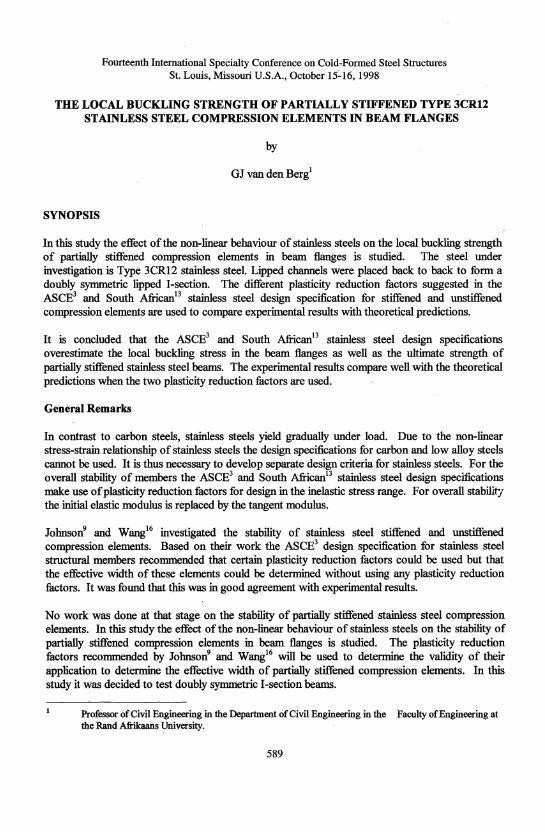
Fourteenth International Specialty Conference on Cold-Fanned Steel Structures St. Louis, Missouri U.S.A., October 15~16, 1998
THE LOCAL BUCKLING STRENGTH OF PARTIALLY STIFFENED TYPE 3CR12 STAINLESS STEEL COMPRESSION ELEMENTS IN BEAM FLANGES
by
OJ van den Berg1
SYNOPSIS
In this study the effect of the non-linear behaviour of stainless steels on the local buckling strength of partially stiffened compression elements in beam flanges is studied. The steel under investigation is Type 3CR12 stainless steel. Lipped channels were placed back to back to form a doubly symmetric lipped I-section. The different pIaSticity reduction metors suggested in the ASeE3 and South African13 stainless steel design specification for stiffened and unstiffened compression elements are used to compare experimental results with theoretical predictions.
It is concluded that the ASCE3 and South Africanl3 stainless steel design specifications overestimate the local buckling stress in the beam flanges as well as the ultimate strength of partially stiffened stainless steel beams. The experimental results compare well with the theoretical predictions when the two plasticity reduction factors are used.
General Remarks
In contrast to carbon steels, stainless steels yield gradually under load. Due to the non-linear stress-strain relationship of stainless steels the design specifications for carbon and low alloy steels cannot be used. It is thus necessary to develop separate design criteria for stainless steels. For the overall stability of members the-ASeE3 and South Africanl3 stainless steel design specifications make use of plasticity reduction metors for design in the inelastic stress range. For overall stabilirj the initial elastic modulus is replaced by the tangent modulus.
Johnson9 an<i Wangl6 investigated the stability of stainless steel stiffened and unstiffened compression elements. Based on their work the ASeE3 design specification for stainless steel structural members recommended that certain plasticity reduction factors could be used but that the effective width of these elements could be determined without using any plasticity reduction :factors. It was found that this was in good agreement with experimental results.
No work was done at that stage on the stability of partially stiffened stainless steel compression elements. In this study the effect of the non-linear behaviour of stainless steels on the stability of partially stiffened compression elements in beam flanges is studied. The plasticity reduction metors recommended by JohnsoJl and Wangl6 will be used to determine the validity of their application to determine the effective width of partially stiffened compression elements. In this study it was decided to test doubly symmetric I -section beams.
Professor of Civil Engineering in the Department of Civil Engineering in the Faculty of Engineering at the Rand Afrikaans University.
589
590
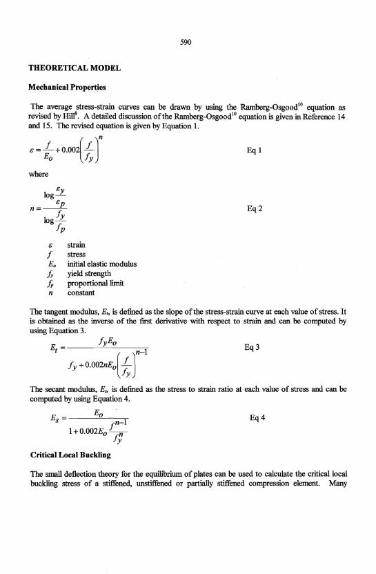
THEORETICAL MODEL
Mechanical Properties
The average stress-strain curves can be drawn by using the Ramberg-OsgoodlO equation as revised by HillS. A detailed discussion of the Ramberg-OsgoodlO equation is given in Reference 14 and 15. The revised equation is given by Equation 1.
e = L+ o.oo2[LJn Eo fy
Eq 1
where
e log 1
e n=--P- Eq2
logfy
fp
e strain f stress Eo initial elastic modulus h yield strength fp proportional limit n constant
The tangent modulus, E" is defined as the slope of the stress-strain curve at each value of stress. It is obtained as the inverse of the first derivative with respect to strain and can be computed by using Equation 3.
Eq3
The secant modulus, Es, is defined as the stress to strain ratio at each value of stress and can be computed by using Equation 4.
E _ Eo S - fn-l
1+ O.002Eo -nfy
Critical Local Buckling
Eq4
The small deflection theory for the equilibrium of plates can be used to calculate the critical local buckling stress of a stiffened, unstiffened or partially stiffened compression element. Many
591
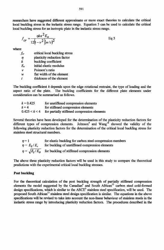
researchers have suggested different approximate or more exact theories to calcu1ate the critical local buckling stress in the inelastic stress range. Equation 5 can be used to calculate the critical local buckling stress for an isotropic plate in the inelastic stress range.
l1kn2Eo Eq5
where Icr critical local buckling stress 11 plasticity reduction :fuctor k buckling coefficient Eo initial elastic modulus v Poisson's ratio w flat width of the element t thickness of the element
The buckling coefficient k depends upon the edge rotational restraint, the type of loading and the aspect ratio of the plate. The buckling coefficients for the different plate elements under consideration can be summarised as follows.
k= 0.425 k=4 0.425 <k<4
for unstiffened compression elements for stiffened compression elements for partially stiffened compression elements
Several theories have been developed for the determination of the plasticity reduction :fuctors for different types of compression elements. Johnsorr and Wang!6 showed the validity of the following plasticity reduction :fuctors for the determination of the critical local buckling stress for stainless steel structural members.
11=1 11 = Esl Eo
11= ~EtlEo
for elastic buckling for carbon steel compression members for buckling ofunstiffened compression elements.
for buckling of stiffened compression elements
The above thrtie plasticity reduction :fuctors will be used in this study to compare the theoretical predictions with the experimental critical local buckling stresses.
Post buckling
For the theoretical calculation of the post buckling strength of partially stiffened compression elements the model suggested by the Canadian6 and South African!2. carbon steel cold-formed design specifications, which is similar to the ASCE3 stainless steel specification, will be used. The proposed South African!3 stainless steel design specification is similar. The equations in the above specifications will be revised to take into account the non-linear behaviour of stainless steels in the inelastic stress range by introducing plasticity reduction :fuctors. The procedures descnbed in the
592
South African12 and Canadian6 carbon steel cold-formed design specifications and the proposed South African13 stainless steel design specification will be followed.
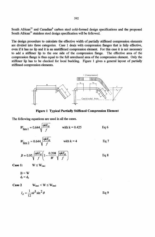
The design procedure to calculate the effective width of partially stiffened compression elements are divided into three categories. Case 1 deals with compression flanges that is fully effective, even if it has no lip and it is an unstiffened compression element. For this case it is not necessary to add a stiffener lip to the one side of the compression flange. The effective area of the compression flange is thus equal to the full unreduced area of the compression element. Only the stiffener lip has to be checked for local buckling. Figure 1 gives a general layout of partially stiffened compression elements.
f (Compression)
Figure 1 Typical Partially Stiffened Compression Element
The following equations are used in all the cases.
with k = 0.425
withk=4
B = 0.95~~~O (1- 0.;8 ~~~o J Case 1:
B=W dr = de
Case 2
W~WIiml
Eq6
Eq7
Eq8
Eq9
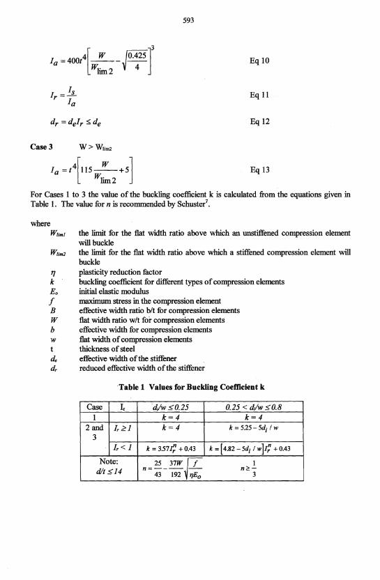
1a =400t4[~-l.42513 Wlim2 4
Case 3 W>WUm2
1a = t4[115~+51 Wlim2
593
Eql0
Eqll
Eq 12
Eq 13
For Cases 1 to 3 the value of the buckling coefficient k is calculated from the equations given in Table 1. The value for n is recommended by Schuster'.
where Wlirill the limit for the flat width ratio above which an unstiffened compression element
will buckle Wlim2 the limit for the flat width ratio above which a stiffened compression element will
buckle 1'/ plasticity reduction factor k buckling coefficient for different types of compression elements Eo initial elastic modulus f maximum stress in the compression element B effective width ratio bit for compression elements W flat width ratio wIt for compression elements b effective width for compression elements w flat width of compression elements t thickness of steel de effective width of the stiffener dr reduced effective width of the stiffener
Table 1 Values for Buckling Coefficient k
Case I, "d/w <0.25 0.25 < d/w <0.8 1 k=4 k=4
2 and 1r~1 k=4 k=525-5di lw
3 1r< 1 k = 357 t,! + 0.43 k=[4.82-5di Iw]I; +0.43
Note: 25 37W if I dit $14 n = 43 - 192 "Eo
n~-3
594
EXPE~ENTALPROCEDURE
Mechanical Properties
Uniaxial compres~ion tests were carried out on specimens taken from the steel in the longitudinal directions. The tensile tests were carried out in accordance with the procedures outlined by the ASTM Standard A370-772•
Beam Tests
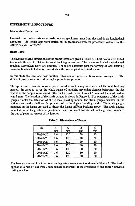
The average overall dimensions of the beams tested are given in Table 2. Short beams were tested to exclude the effect of lateral torsional buckling interaction. The beams are loaded statically and readings were taken every two seconds. The test is continued past the forming of local buckling waves until Ultimate failure is reached when the load applied starts to decrease.
In this study the local and post buckling behaviour of lipped-I-sections were investigated. The different profiles were furmed through a press brake process
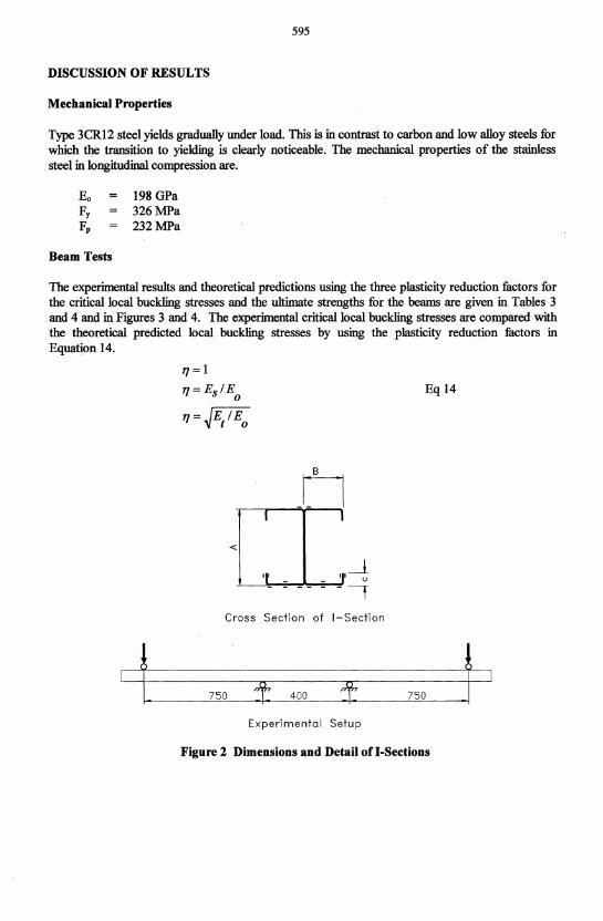
The specimen cross-sections were proportioned in such a way to observe all the local buckling modes. In order to cover the whole range of variables governing element behaviour, the flat widths of tht; flanges were varied. The thickness of the sheet was 1.6 mm and the inside radius was 3 mm. The location of the strain gauges is shown in Figure 2. The placement of the strain gauges enables the detection of all the local buckling modes. The strain gauges mounted on the stiffener are used to indicate the presence of the local plate buckling mode. The strain gauges mounted on the flange are used to detect the flange stiffener buckling mode. The strain gauges mounted on the flange-stiffener jlmction are used to detect distortional buckling, which refers to the out-of-plane movement of the junction.
Table 2. Dimensions of Beams
No t A B C mm mm mm mm
120x30x20 1.6 120 30 20 120x40x20 1.6 120 40 20 120x50x20 1.6 120 50 20 120x60x20 1.6 120 60 20 120x70x20 1.6 120 70 20 120x80x20 1.6 120 80 20 120x90x20 1.6 120 90 20
The beams are tested in a four point loading setup arrangement as shown in Figure 2. The load is applied at a rate of less than 2 mm /minute movement of the crosshead of the Instron mllversal testing machine
595
DISCUSSION OF RESULTS
Mechanical Properties
Type 3CRI2 steel yields gradually under load. This is in contrast to carbon and low alloy steels for which the transition to yielding is clearly noticeable. The mechanical properties of the stainless steel in longitudinal compression are.
Eo 198 GPa Fy 326MPa Fp 232MPa
Beam Tests
The experimental results and theoretical predictions using the three plasticity reduction factors for the critical local buckling stresses and the ultimate strengths for the beams are given in Tables 3 and 4 and in Figures 3 and 4. The experimental critical local buckling stresses are compared with the theoretical predicted local buckling stresses by using the plasticity reduction fitctors in Equation 14.
11 = I 11 = Esl E
0 Eq 14
11=~E/Eo
tl I I
«
'I' - - 'I'--! - -, Cross Section of I-Section
t 750 f 400 f 750 ~ Experimental Setup
Figure 2 Dimensions and Detail on-Sections
596
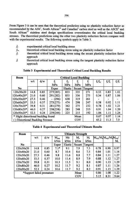
From Figure 3 it can be seen that the theoretical prediction using no plasticity reduction factor as recommended by the AISI1, South Africanl2 and Canadian6 carbon steel as well as the ASCE3 and South African13 stainless steel design specifications overestimates the critical local buckling stresses. The theoretical predictions using the other two plasticity reduction factors compare well with the experimental results. The following symbols apply in Table 3.
Ie experimental critical local buckling stress ler theoretical critical local buckling stress using no plasticity reduction factor Is theoretical critical local buckling stress using the secant plasticity reduction factor
approach f, theoretical critical local buckling stress using the tangent plasticity reduction factor
approach
Table 3 Experimental and Theoretical Critical Local Buckling Results
Beam Critical Local Buckling wit dJw , tr f, t; '/tr fJf, ,It;
MPa MPa MPa MPa No Exper Elastic Secant Tangent
120x30x20 14.8 0.85 277(285) 833 335 271 0.33 0.83 1.02 120x40x20* 21.0 0.60 291(282) 855 336 275 0.34 0.87 1.06 120x50x20* 77.3 0.46 - (296) 638 319 261 - - -120x60x20* 33.5 0.37 275(275) 474 298 247 0.58 0.92 1.11 120x70x20* 39.8 0.31 281(279) 362 275 232 0.78 1.02 1.21 120x80x20* 46.0 0.27 258(258) 283 248 215 0.91 1.04 1.20 120x90x20* 52.3 0.24 239(244) 225 215 192 1.06 1.11 1.24 * Slight distortional buckling found Mean . 0.67 0.97 1.14 ( ) Distortional Buckling Stresses COY 45.2 11.3 7.9
Table 4 Experimental and Theoretical Ultimate Results
Beam Ultimate Strength wit dJw Mexp Me Me Mt ~xp/M. MexplMs ~xp/
kNm kNm kNm kNm Mt No Exper Elastic Secant Tangent
120x30x20 14.8 0.85 7.1 * 9.1 7.9 7.3 0.78 0.90 0.97 120x40x20 21.0 0.60 8.7 10.4 8.6 7.5 0.84 1.01 1.16 120x50x20 27.3 0.46 9.8 11.6 8.8 7.7 0.84 1.11 1.27 120x60x20 33.5 0.37 10.0 11.4 8.9 7.9 0.88 1.12 1.27 120x70x20 39.8 0.31 10.3 11.5 9.1 8.0 0.90 1.13 1.29 120x80x20 .46.0 0.27 10.2 11.7 9.2 8.1 0.87 1.11 1.26 120x90x20 52.3 0.24 10.6 11.7 9.2 8.2 0.91 1.15 1.29
*Support failed premature Mean 0.86 1.08 1.22 COY 5.15 8.31 9.64
597
400'
.. .. ~ 300 ... ;3 ...
rI.l DII
~ 200 .. = IIQ
.:III
'" ~ ·C \oJ
-- Elastic Critical Buckling Curve - Secant Modulus Buckling Curve - - Tangent Critical Buckling Curve
• Experimental Results
0.1 0.2 0.3 0.4 0.5 0.6 0.7 0.8 0.9
Figure 3 Critical Local Buckling Strength of Sections
1.2
1.0 ~--•
0.8
f 0.6
-- Elastic Moment Curve 0.4 - Secant Modulus Curve
- - Tangent Modulus Curve • Expeimental results
0.2 0.0 0.2 0.4 0.6 0.8 1.0
dyw
Figure 4 Ultimate Strength of Sections
598
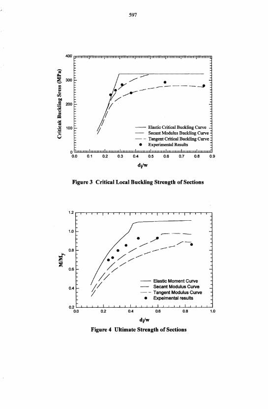
The experimental results and theoretical prediction for the ultimate capacities of the beams are given in Table 4 and in Figure 4. From Table 4 it can be seen that the theoretical predictions using the secant and tangent modulus approach plasticity reduction factors are generally in better agreement with the experimental results. In a study by Buitendag4,5 and Reynekell on the strength of partially stiffened stainless steel compression members similar results were obtained. The following symbols apply in Table 4.
Mexp experimental ultimate failure moment Me elastic failure moment Us theoretical moment using the secant approach plasticity reduction factor M, theoretical moment using the tangent approach plasticity reduction factor
CONCLUSIONS
It is concluded in this study that the ASCE3 and South African13 stainless steel design specifications overestimate the local buckling stress as well as the ultimate strength of partially stiffened stainless steel compression elements. The experimental results compare well with the theoretical predictions when the two plasticity reduction factors are used.
From the limited number of tests carried out in this study it can be concluded that there is a general tendency for the elastic theory to overestimate the ultimate capacity of a section. For determining the ultimate capacity of a partially stiffened beam section the plasticity reduction factor using the secant modulus approach are in better agreement with the experinlental results than the tangent modulus approuch.
REFERENCES
1. American Iron and Steel Institute. Cold-Formed Steel Design Manual. 1986. 2. American Society for Testing and Materials. A370-77. Standard Methods and Definitions
for Mechanical Testing of Steel Products. Annual Book of ASTM Standards. 1981. 3. American Society of Civil Engineers. Specification for the Design of Cold-Formed
Stainless Steel Structural Members. ANSIIASCE-8-90. 1991. 4. Buitendag, Y. The Strength of Partially Stiffened Stainless Steel Compression Members.
M.Ing Dissertation. Rand Afrikaans University. Johannesburg. South Africa. 1995. 5. Buitendag, Y, Van den Berg, GJ. The Strength of Partially Stiffened Stainless Steel
Compression Members. Twelfth Specialty Conference on Cold-Fomled Steel Structures. St Louis. Missouri. 1994.
6. Canadian Standard Association. Cold-Formed Steel Structural Members. CSA Standard Can3-S-136 1984.
7. Dinovitzer, AS, Sohrabpour, M, Schuster, RM. Observation and Comments Pertaining to CAN/CSA-s136-M89. Eleventh Specialty Conference on Cold-Formed Steel Structures. St Louis. Missouri. 1992.
8. Hill, BN. Determination of Stress-Strain Relationships from Offset Strength Values. NACA Technical Note No 927. Feb 1944.
599
9. Johnson, AL. The Structural Performance of Austenitic Stainless Steel Members. Report No. 327. Cornell University. Ithaca. New York. November 1966.
10. Ramberg, W, Osgood, WR. Description of Stress-Strain Curves by Three Parameters. NACA Technical Note No 902. July 1942.
11. Reyneke, W. The Strength of Partially Stiffened Stainless Steel Compression Flanges. M.lng Dissertation. Rand Afrikaans University. Johannesburg. South Africa. 1996. (In Preparation).
12. South African Bureau of Standards. SABS 0162-2:1993. Code of Practice. The Structural Use of Steel. Limit-States Design of Cold-Formed Steelwork. 1994.
13. South African Bureau of Standards. SABS 0162-4:1996. Draft Code of Practice. The Structural Use of Steel. Limit-States Design .of Cold-Formed Stainless Steel Members. 1996.
14. Van den Berg, GJ. The Torsional Flexural Buckling Strength of Cold-Formed Stainless Steel Columns. D.lng. Thesis. Rand Afrikaans University. Johannesburg. South Africa. 1988.
20. Van der Merwe, P. Development of Design Criteria for Ferritic Stainless Steel ColdFormed Structural Members and Connections. Ph.D. Thesis. University of Missouri-Rolla. 1987.
16. Wang, ST. Cold-Rolled Austenitic Stainless Steel. Report No. 334. Cornell University. Ithaca. New York. July 1969.