the structural behaviour of stiffened composite panels ... - ICCM
10
THE STRUCTURAL BEHAVIOUR OF STIFFENED COMPOSITE PANELS SUBJECTED TO IN-PLANE SHEAR LOADING Mariano A. Arbelo, Maurício V. Donadon, Sérgio F. M. de Almeida Instituto Tecnológico de Aeronáutica – ITA/CTA/IEM Praça Marechal Eduardo Gomes, 50, São José dos Campos-SP, Brazil [email protected] SUMMARY This work deals with a numerical investigation on the structural behaviour of stiffened composite panels subjected to in-plane shear loads in the post-buckling regime. The modelling approach takes into account large deformations and material nonlinearity effects by using a damage mechanics based progressive failure model. Keywords: Composite, post-buckling, damage mechanics, finite elements INTRODUCTION Recently a considerable effort has been dedicated towards the development of fast and reliable design procedures for buckling, postbuckling and collapse analyses of fibre composite stiffened panels of future fuselage structures through the COCOMAT and POSICOSS european projects [1]. The procedures must account for degradation due to static as well as low cycle loading in the postbuckling range. It is well-known that thin-walled structures made of carbon fibre reinforced plastics are able to tolerate repeated buckling without any change in their buckling behaviour. However, it has yet to be established, how deep into the postbuckling regime loading one can go without severely damaging the structure, and how this can be reliably predicted by fast and accurate simulation procedures. Within this context, this paper presents a detailed numerical investigation on the post-buckling behaviour of stiffned composite panels subjected to in-plane shear loading. A series of finite element models were developed using ABAQUS FE code to estimate the post-buckling behaviour of stiffened composite panels loaded in shear. Simulations were carried taking into account geometric and material non-linearities, geometric imperfections and interactions between fibre failure and matrix cracking effects by using a damage mechanics based constitutive failure model. The proposed failure model accounts for in-plane shear non-linearities and it enables prediction of failure progression within an energy based framework [3,4] The numerical analyses were performed out quasi-statically using the Dynamic Relaxation Method. Preliminary results indicate that the stiffened composite shear webs have significant post-buckling strength. A comparison between numerical predictions and experimental results in terms of load-displacement is presented as well as a comparison
-
Upload
khangminh22 -
Category
Documents
-
view
1 -
download
0
Transcript of the structural behaviour of stiffened composite panels ... - ICCM

THE STRUCTURAL BEHAVIOUR OF STIFFENED COMPOSITE PANELS SUBJECTED TO IN-PLANE
SHEAR LOADING
Mariano A. Arbelo, Maurício V. Donadon, Sérgio F. M. de Almeida Instituto Tecnológico de Aeronáutica – ITA/CTA/IEM
Praça Marechal Eduardo Gomes, 50, São José dos Campos-SP, Brazil [email protected]
SUMMARY
This work deals with a numerical investigation on the structural behaviour of stiffened composite panels subjected to in-plane shear loads in the post-buckling regime. The modelling approach takes into account large deformations and material nonlinearity effects by using a damage mechanics based progressive failure model.
Keywords: Composite, post-buckling, damage mechanics, finite elements
INTRODUCTION
Recently a considerable effort has been dedicated towards the development of fast and reliable design procedures for buckling, postbuckling and collapse analyses of fibre composite stiffened panels of future fuselage structures through the COCOMAT and POSICOSS european projects [1]. The procedures must account for degradation due to static as well as low cycle loading in the postbuckling range. It is well-known that thin-walled structures made of carbon fibre reinforced plastics are able to tolerate repeated buckling without any change in their buckling behaviour. However, it has yet to be established, how deep into the postbuckling regime loading one can go without severely damaging the structure, and how this can be reliably predicted by fast and accurate simulation procedures. Within this context, this paper presents a detailed numerical investigation on the post-buckling behaviour of stiffned composite panels subjected to in-plane shear loading. A series of finite element models were developed using ABAQUS FE code to estimate the post-buckling behaviour of stiffened composite panels loaded in shear. Simulations were carried taking into account geometric and material non-linearities, geometric imperfections and interactions between fibre failure and matrix cracking effects by using a damage mechanics based constitutive failure model. The proposed failure model accounts for in-plane shear non-linearities and it enables prediction of failure progression within an energy based framework [3,4] The numerical analyses were performed out quasi-statically using the Dynamic Relaxation Method. Preliminary results indicate that the stiffened composite shear webs have significant post-buckling strength. A comparison between numerical predictions and experimental results in terms of load-displacement is presented as well as a comparison

between predicted and experimental out-of-plane displacement fringes in the central sub-panel subjected to shear loading.
DAMAGE MECHANICS BASED FAILURE MODEL
The formulation proposed to model progressive failure in composites is based on the smeared cracking approach [4,5]. The smeared cracking formulation relates the specific or volumetric energy, which is defined by the area underneath the stress-strain curve, with the strain energy release rate of the material. The method assumes a strain softening constitutive law for modeling the gradual stiffness reduction due to the micro-cracking process within the cohesive or process zone of the material. In order to avoid pathological problem associated with strain localization and mesh dependence during softening, the softening portion of a stress-strain curve is adjusted according to the element topology and cracking direction for each failure mode using an advanced objectivity algorithm. The proposed failure model was implemented into ABAQUS finite element code as a user defined material model within shell elements.
Failure criteria
The failure criteria used to detect damage initiation for all in-plane failure modes are all based on the maximum stress criteria [6] and they are given as follows,
Tensile fibre failure mode:
1111( )t
ft
FX
σσ = (1)
Compression fibre failure mode:
1111( )c
fc
FX
σσ = (2)
Tensile matrix cracking mode:
2222( )t
mt
FY
σσ = (3)

Compression matrix cracking mode:
2222( )c
mc
FY
σσ = (4)
Inplane shear failure mode:
1212
12
( )smF
S
ττ = (5)
where tX , cX , tY and cY are the tensile and compression strengths in the fibre and
matrix directions, respectively. 12S is the in-plane shear strength.
Damage evolution laws
Damage evolution law for fibre failure
The proposed damage evolution law for fibre failure is given by [3]
11 1 2 1 2 1 2( , )f f f f f fd λ λ λ λ λ λ= + − (6)
with
11 1,01 *
1,0 11
2
2
t t tff
t t tf t
G
G X l
ε ελ
ε ε −
= − (7)
11 1,02 *
1,0 11
2
2
c c cff
c c cf c
G
G X l
ε ελ
ε ε −
= − (8)
where the values for both functions 1 2, [0,1]f fλ λ ∈ . tfG and c
fG are the intralaminar
fracture toughnesses associated with fibre breakage in tension and compression, respectively. 1,0
tε and 1,0cε are maximum strains prior to catastrophic failure in tension
and compression in the fibre direction, respectively. In order to account for damage
irreversibility effects max11 11 1,0max ( ) ,k ktε ε ε = where max
11 ( )tε is the maximum achieved
strain in the strain versus time history. The superscript k refers to the fibre failure mode, that is, k t= for tensile fibre failure and k c= for compression fibre failure. The

characteristic length *l is used for mapping the material process (or microcracking) zone into the finite element mesh. For fibre failure modes *l is computed in terms of the isoparametric coordinates ( , )j jξ η for each integration point j according to the
following expression,
1
*
1
( , ) ( , )( , ) cos( ) sin( )
cni j j i j j
j j j j ii
N Nl
x y
ξ η ξ ηξ η θ θ φ
−
=
∂ ∂ = + ∂ ∂ ∑ (9)
where j fibreθ θ= being fibreθ the fibre orientation angle for each integration point. For
four nodes shell elements 4cn = , ( , )i j jN ξ η are bi-linear interpolation functions and iφ
is defined as crack band discontinuity function. Details about the derivation of the expression for the characteristic length for orthotropic smeared cracking modes can be found in Donadon et al. [5].
Damage evolution law for matrix cracking
The proposed damage evolution law for matrix cracking is given by [3]
22 1 2 1 2 1 2( , )m m m m m md λ λ λ λ λ λ= + − (10)
with
22 2,01 *
2,0 22
2
2
t ttm m
t t tm t
G
G Y l
ε ελ
ε ε −
= − (11)
22 2,02 *
2,0 22
2
2
c ccm m
c c cm c
G
G Y l
ε ελ
ε ε −
= − (12)
where the values for both functions 1 2, [0,1]m mλ λ ∈ . tmG and c
mG are the intralaminar
fracture toughnesses associated with matrix breakage in tension and compression, respectively. 2,0
tε and 2,0cε are maximum strains prior to catastrophic failure in tension
and compression in the matrix direction, respectively. In order to account for damage
irreversibility effects max22 22 2,0max ( ) ,k ktε ε ε = where max
22 ( )tε is the maximum achieved
strain in the strain versus time history. The superscript k refers to the matrix failure mode, that is, k t= for tensile matrix failure and k c= for compression matrix

cracking. The characteristic *l associated with matrix failure modes is obtained from Eq. (9) with 090j fibreθ θ= + for each integration point.
Damage evolution law for in-plane shear failure
The damage evolution for in-plane shear failure is given by [3]
( )( )( )
12, 12 12,0 12,
12 12
12, 12,0 12 12 12,0
2( )
inf f
in inf
dγ γ γ γ
γγ γ γ γ γ
− − =+ − −
(13)
with
12, *12
2 sf
G
S lγ = (14)
where 12,0inγ is the inelastic strain at failure and sG is the in-plane shear intralaminar
fracture toughness. The characteristic length *l for in-plane shear failure is assumed to be the same as the one used for fibre failure modes.
Non-linear rate dependent in-plane shear model
The observed behaviour of glass and carbon fibres laminates generally shows marked rate dependence in matrix dominated shear failure modes and for this reason a rate dependent constitutive model has been used to model the in-plane shear behaviour. The constitutive model formulation is based on previous work carried out by Iannucci and Donadon [7], and it accounts for shear non-lineatities, irreversible strains and damage within the Representative Volume Element (RVE) of the material. The stress-strain behaviour for in-plane shear failure is defined as follows,
12 12 12Gτ α γ= (15)
with
( )2 12012 12 1 1cG G c e γ−= + − (16)
where 012G is the initial shear modulus and 1c and 2c are material constants obtained
from in-plane shear tests. α is the strain-rate enhancement given by the following law,
12
31 ceγ
α = +ɺ
(17)
where 3c is a material constant obtained from dynamic in-plane shear tests. By
decomposing the total shear-strain into inelastic 12inγ and 12
eγ elastic components, the inelastic shear strain can be written in terms of the elastic and total strain components as follows,
12 1212 12 12 12 0
12
( )in e
G
τ γγ γ γ γ= − = − (18)
Stress degradation procedure
The resultant degraded stresses at ply level are given by
11 1111 1 2
22 11 1 2 22 1 2 22
12 1212 12
(1 ( , )) 0 0
0 (1 ( , ))(1 ( , )) 0
0 0 (1 ( ))
d f f
d f f m m
d
d
d d
d
σ σλ λσ λ λ λ λ σ
γτ τ
− = − − −
(19)
where
11 1111 12 22
22 21 11 22 2212 21
1212 12
01
0(1 )
0 0
E v E
v E Ev v
G
σ εσ ετ γ
= −
(20)
EXPERIMENTAL TESTS
The composite stiffened panel tested in this work is representative of a typical aircraft fuselage. The panel was clamped on both sides and loaded in shear according to the experimental setup depicted in Fig. 1 (A). This setup ensures that the central sub-panel is under pure shear along loading line. Strain gauges were bonded on top and bottom faces of the panel in order to measure the in-plane strains during the test and detect local buckling in the sub panels. The applied load and vertical displacement were also measured. The panel was cyclic loaded beyond the linear critical buckling load up to 15000 N with equal load increments of 150 N. The load was cyclic applied to investigate the inelastic effects associated with cumulative damage and plasticity in the structural response. The out-of-plane displacements of the central sub-panel were
measured using the non-contact optical device shown in Fig. 1 (B). For each load level, two images were captured. The first image was taken for unloaded panel whereas the second was captured after applying the loads. The subtraction of the two images yields the panel out-of-plane displacements due to the applied loading.
Figure 1. Experimental setup
FINITE ELEMENT MODEL AND POST-BUCKLING ANALYSES
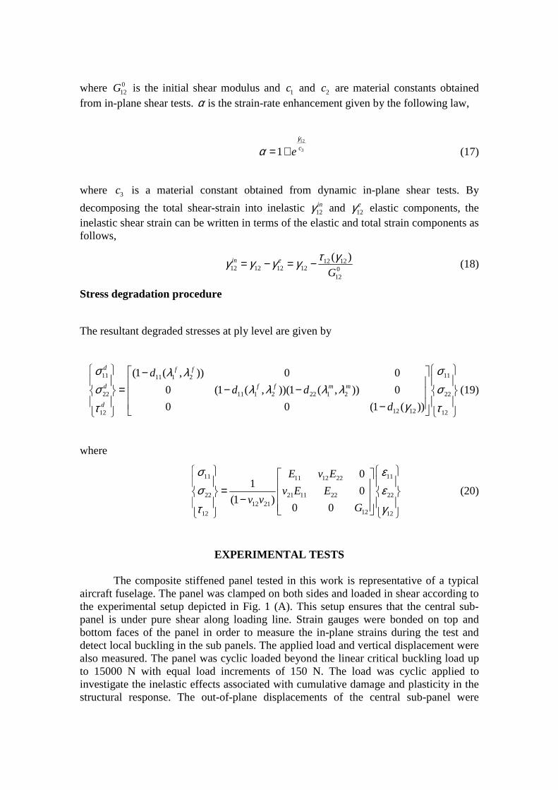
The finite element model consists of a stiffened panel composed by skin and stiffeners perfectly tied together with a loading frame as shown in Fig. 2. The skin and stiffeners were modelled using shell elements and the loading frame was modelled using brick elements both available in ABAQUS finite element code. The panel was assumed to be clamped in both ends and loaded under displacement control at the point indicated in the Fig. 2.
Figure 2. Finite element model
The analyses were carried out using the Dynamic Relaxation Method taking into account geometric and material non-linearity effects using the proposed damage mechanics based failure model. Firstly, a linear buckling analysis was performed to compute the linear buckling loads and their respective buckling modes. The buckling loads together with the buckling modes are shown in Fig. 3.
(A) (B)
X
Y
Z
δ
X
Y
Z
δ

Figure 3. Buckling loads and buckling modes
Subsequently, quasi-static analyses including geometric imperfections and
progressive failure modelling were carried out. In order to assign an initial geometric imperfection, a linear combination of buckling modes (with scale factors αi) is superimposed to the initial geometry of the model. The general equation that represents the implementation of the initial geometric imperfection in the model is given as follows,
0( , , ) ( , , ) . ( , , )
i ii
p x y z p x y z X x y zα= +∑ (21)
where: p (x, y, z) is the position of each node in the perturbed mesh, p0 (x, y, z) is the position of each node in the original mesh and Xi(x,y,z) is the i-th buckling mode. The initial imperfection was approximated as a linear combination between the first four buckling modes. αi represents the contribution of each buckling mode for the initial imperfection. For simplicity in the present study the values of αi were assumed to be equal for all modes. A comparison between predicted and experimental load versus displacement curves for the different cases studied in this work is shown in Fig. 4.
0
2000
4000
6000
8000
10000
12000
14000
16000
0 0.5 1 1.5 2 2.5 3 3.5Prescribed Displacement (mm)
Rea
ctio
n F
orc
e (N
)
w/o Imp. w/o Damage
w/o Imp. w Damage
w Imp. (0,5t) w Damage
w Imp. (1,0t) w Damage
Experimental
Figure 4. Comparison between predicted and experimental responses

The predicted response neglecting damage and geometric imperfections is shown in blue (w/o Imp. w/o Damage). The numerical result obtained for the case considering damage only is shown in red (w/o Imp. w Damage). The numerical predictions for the cases considering both damage and geometric imperfections with αi = 0.5t (w Imp. (0.5t) w Damage) and αi = 1.0t (w Imp. (1.0t) w Damage) are shown in green and light blue, respectively, where t is the panel skin thickness. According to Fig. 4, the numerical predictions agree remarkably well with the experimental results. A good correlation between predicted and measured out-of-plane displacements fringes was also obtained at the maximum load level, as shown in Fig. 5.
0.3819
-4.3076
0.3819
-4.3076
0.3819
-4.3076
(a) Experimental (b) Predicted
Figure 5. Comparison between predicted and experimental out-of-plane displacement fringes obtained for the central sub-panel loaded in shear
It is also worth noticing that the panel is insensitive to the magnitude of the
initial perfections. Moreover, no inelastic effects associated with cumulative damage and plasticity was observed in the structural response within the applied load range. The absence of these effects was also confirmed by the experiments.
CONCLUSIONS
This paper presented a detailed numerical and experimental investigation on the post-buckling behaviour of stiffened composite panels subjected to shear loads. An experimental apparatus and test setup were developed to characterise experimentally nonlinear behaviour of composite panels in the post-buckling regime. A methodology for analysis of the post-buckling behaviour of composite shear webs was also presented. The proposed methodology accounts for failure, material non-linearity/degradation, geometric imperfections and geometric non-linearity effects. The numerical and experimental results indicated that the post-buckling behaviour of the panels prior to collapse was not significantly affected by the geometric imperfections and their magnitudes.

ACKNOWLEDGEMENTS
The authors acknowledge the financial support received for this work from the Fundação de Amparo a Pesquisa do Estado de São Paulo (Fapesp), contracts numbers 2007/02710-4, 2006/06808-6 and CNPq Grant 305601/2007-5.
References
1. Degenhardt R., Rolfes R., Zimmermann R., Rohwer K., “COCOMAT—improved material exploitation of composite airframe structures by accurate simulation of postbuckling and collapse 2006;73:175-178.
2. Arbelo, Mariano A. “Comportamento Estrutural de Painéis Laminados em Materiais Compósitos Sujeitos a Cargas de Cisalhamento no Plano”. 2008. 203f. Master´s Thesis – Instituto Tecnológico de Aeronáutica, São José dos Campos.
3. Donadon, M. V., Almeida, S. F. M., Faria A. R., Arbelo, M. A., An energy based failure model for FRP laminates. (Submitted to Composite Structures).
4. Donadon, M.V., “The impact behaviour of composite structures manufactured using resin infusion under flexible tooling”, Ph.D Thesis, Department of Aeronautics, Imperial College London, England, UK, 375 p.
5. Donadon, M.V., Iannucci L., Falzon B. G., Hodgkinson J. M., Almeida S.F.M., 2008, “A progressive failure model for composite laminates subjected to low velocity impact damage”, Computers & Structures 2008;86:1232-1252.
6. Jones R.M., “Mechanics of composite materials”, Ed. Taylor and Francis Inc., USA, 275 p, 1999.
7. Iannucci L. and Donadon M.V., “Bird strike modelling using a new woven glass failure model”, Proceedings of the LS-DYNA International Conference, Michigan, Dearborn USA, 2006.