Comfort Panels INOX, ITC INOX - Smart Factory
42
___________________ ___________________ ___________________ ___________________ ___________________ ___________________ ___________________ ___________________ SIMATIC HMI devices Comfort Panels INOX, ITC INOX Compact Operating Instructions 09/2017 A5E33472156-AI Preface Overview 1 Safety instructions 2 Installing and connecting the device 3 Cleaning the device 4 Technical specifications 5 Technical Support A List of abbreviations B
-
Upload
khangminh22 -
Category
Documents
-
view
1 -
download
0
Transcript of Comfort Panels INOX, ITC INOX - Smart Factory
___________________
___________________
___________________
___________________
___________________
___________________
___________________
___________________
SIMATIC
HMI devices Comfort Panels INOX, ITC INOX
Compact Operating Instructions
09/2017 A5E33472156-AI
Preface
Overview 1
Safety instructions 2
Installing and connecting the device
3
Cleaning the device 4
Technical specifications 5
Technical Support A
List of abbreviations B

Siemens AG Division Digital Factory Postfach 48 48 90026 NÜRNBERG GERMANY
A5E33472156-AI Ⓟ 09/2017 Subject to change
Copyright © Siemens AG 2017. All rights reserved
Legal information Warning notice system
This manual contains notices you have to observe in order to ensure your personal safety, as well as to prevent damage to property. The notices referring to your personal safety are highlighted in the manual by a safety alert symbol, notices referring only to property damage have no safety alert symbol. These notices shown below are graded according to the degree of danger.
DANGER indicates that death or severe personal injury will result if proper precautions are not taken.
WARNING indicates that death or severe personal injury may result if proper precautions are not taken.
CAUTION indicates that minor personal injury can result if proper precautions are not taken.
NOTICE indicates that property damage can result if proper precautions are not taken.
If more than one degree of danger is present, the warning notice representing the highest degree of danger will be used. A notice warning of injury to persons with a safety alert symbol may also include a warning relating to property damage.
Qualified Personnel The product/system described in this documentation may be operated only by personnel qualified for the specific task in accordance with the relevant documentation, in particular its warning notices and safety instructions. Qualified personnel are those who, based on their training and experience, are capable of identifying risks and avoiding potential hazards when working with these products/systems.
Proper use of Siemens products Note the following:
WARNING Siemens products may only be used for the applications described in the catalog and in the relevant technical documentation. If products and components from other manufacturers are used, these must be recommended or approved by Siemens. Proper transport, storage, installation, assembly, commissioning, operation and maintenance are required to ensure that the products operate safely and without any problems. The permissible ambient conditions must be complied with. The information in the relevant documentation must be observed.
Trademarks All names identified by ® are registered trademarks of Siemens AG. The remaining trademarks in this publication may be trademarks whose use by third parties for their own purposes could violate the rights of the owner.
Disclaimer of Liability We have reviewed the contents of this publication to ensure consistency with the hardware and software described. Since variance cannot be precluded entirely, we cannot guarantee full consistency. However, the information in this publication is reviewed regularly and any necessary corrections are included in subsequent editions.

Comfort Panels INOX, ITC INOX Compact Operating Instructions, 09/2017, A5E33472156-AI 3
Preface
Scope of validity These compact operating instructions apply to the following devices which are based on the following standard devices: INOX device Basic device TP700 Comfort INOX, article number 6AV2144-8GC10-0AA0 TP700 Comfort TP900 Comfort INOX, article number 6AV2144-8JC10-0AA0 TP900 Comfort TP1200 Comfort INOX, article number 6AV2144-8MC10-0AA0 TP1200 Comfort TP1500 Comfort INOX, article number 6AV2144-8QC10-0AA0 TP1500 Comfort TP1900 Comfort INOX, article number 6AV2144-8UC10-0AA0 TP1900 Comfort ITC1900 INOX, article number 6AV6646-8AC10-0AA0 ITC1900
These compact operating instructions describe the technical differences between the INOX devices and the corresponding basic devices.
The notes in these compact operating instructions take precedence over statements in the basic operating instructions, the release notes and online help.
Comfort Panels operating instructions (http://support.automation.siemens.com/WW/view/en/49313233)
Industrial Thin Clients operating instructions (http://support.automation.siemens.com/WW/view/en/61187980)
Unless otherwise described in this document, all of the statements made in the general operating manual concerning the basic device are valid for the corresponding INOX device. This means the statements on hardware, operating system, software, configuration, maintenance, and servicing.
Note
This document belongs to the device and will also be required for repeat commissioning. Keep all supplied and supplementary documentation for the entire service life of the device.
Pass on all of these documents to a future owner of the device.

Preface
Comfort Panels INOX, ITC INOX 4 Compact Operating Instructions, 09/2017, A5E33472156-AI
Style conventions Style Convention Scope "Add screen" • Terms that occur in the user interface, for example, dialog name, tab,
button, menu command • Necessary entries, for example, limit value, tag value • Path specification
"File > Edit" Operating sequences, for example, menu item, shortcut menu command <F1>, <Alt+P> Designation of a key on a keyboard
You should also observe notes that are marked as follows:
Note
A note contains important information about the product described in the document and its handling, or a specific section of the document to which you should pay particular attention.
Naming conventions Term Applies to System • System
• Machining center • One or more machines
Device • TP700 Comfort INOX • TP900 Comfort INOX • TP1200 Comfort INOX • TP1500 Comfort INOX • TP1900 Comfort INOX • ITC1900 INOX
Figures This document contains illustrations of the described devices. The figures can deviate from the particularities of the delivered device.

Comfort Panels INOX, ITC INOX Compact Operating Instructions, 09/2017, A5E33472156-AI 5
Table of contents
Preface ........................................................................................................................................ 3
1 Overview ...................................................................................................................................... 7
1.1 Product overview ................................................................................................................. 7
1.2 Scope of delivery ................................................................................................................. 8
1.3 Layout of the devices........................................................................................................... 8
1.4 Interfaces ............................................................................................................................ 9
1.5 Accessories ....................................................................................................................... 10
2 Safety instructions ....................................................................................................................... 11
2.1 General safety instructions ................................................................................................ 11
2.2 Notes on use ..................................................................................................................... 12
2.3 Supplemental notes ........................................................................................................... 12
3 Installing and connecting the device .............................................................................................. 13
3.1 Mounting instructions......................................................................................................... 13
3.2 Preparing for installation .................................................................................................... 13 3.2.1 Check the scope of delivery ............................................................................................... 13 3.2.2 Checking the operating conditions ..................................................................................... 13 3.2.3 Selecting a mounting position ............................................................................................ 14 3.2.4 Checking clearances ......................................................................................................... 16
3.3 Inserting the mounting gasket ............................................................................................ 17
3.4 Positions of the mounting clips for TP1900 Comfort INOX and ITC1900 INOX ................... 19
3.5 Mounting the device .......................................................................................................... 20
3.6 Connecting the device ....................................................................................................... 22
4 Cleaning the device ..................................................................................................................... 23
4.1 Cleaning product ............................................................................................................... 23
4.2 Clean screen for Touch HMI devices ................................................................................. 23
4.3 Chemical Resistance ......................................................................................................... 24
4.4 Working with stainless steel surfaces ................................................................................. 24

Table of contents
Comfort Panels INOX, ITC INOX 6 Compact Operating Instructions, 09/2017, A5E33472156-AI
5 Technical specifications ............................................................................................................... 26
5.1 Certificates and approvals ..................................................................................................26
5.2 Dimension drawings ...........................................................................................................30 5.2.1 Dimension drawing TP700 Comfort INOX ...........................................................................30 5.2.2 Dimension drawing TP900 Comfort INOX ...........................................................................31 5.2.3 Dimension drawing TP1200 Comfort INOX .........................................................................32 5.2.4 Dimension drawing TP1500 Comfort INOX .........................................................................33 5.2.5 Dimension drawing TP1900 Comfort INOX, ITC1900 INOX ................................................34
5.3 Technical specifications ......................................................................................................35
5.4 Classification of environmental conditions ...........................................................................36 5.4.1 Overview ............................................................................................................................36 5.4.2 Classification for storage ....................................................................................................36 5.4.3 Classification for shipping ...................................................................................................37 5.4.4 Classification for stationary and weather-protected use.......................................................38 5.4.5 Climate diagram .................................................................................................................40
A Technical Support ....................................................................................................................... 41
A.1 Service and support ...........................................................................................................41
B List of abbreviations .................................................................................................................... 42
Comfort Panels INOX, ITC INOX Compact Operating Instructions, 09/2017, A5E33472156-AI 7
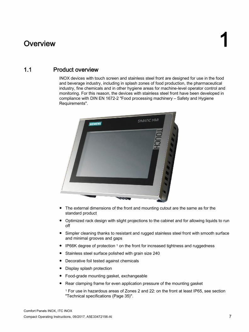
Overview 1 1.1 Product overview
INOX devices with touch screen and stainless steel front are designed for use in the food and beverage industry, including in splash zones of food production, the pharmaceutical industry, fine chemicals and in other hygiene areas for machine-level operator control and monitoring. For this reason, the devices with stainless steel front have been developed in compliance with DIN EN 1672-2 "Food processing machinery – Safety and Hygiene Requirements".
● The external dimensions of the front and mounting cutout are the same as for the
standard product
● Optimized rack design with slight projections to the cabinet and for allowing liquids to run off
● Simpler cleaning thanks to resistant and rugged stainless steel front with smooth surface and minimal grooves and gaps
● IP66K degree of protection 1 on the front for increased tightness and ruggedness
● Stainless steel surface polished with grain size 240
● Decorative foil tested against chemicals
● Display splash protection
● Food-grade mounting gasket, exchangeable
● Rear clamping frame for even application pressure of the mounting gasket 1 For use in hazardous areas of Zones 2 and 22: on the front at least IP65, see section "Technical specifications (Page 35)".

Overview 1.2 Scope of delivery
Comfort Panels INOX, ITC INOX 8 Compact Operating Instructions, 09/2017, A5E33472156-AI
1.2 Scope of delivery Depending on the order, the scope of delivery includes:
● 1 × device
● 1 × accessory pack with the following contents: – 1 mounting gasket – 1 clamping frame – 1 power supply terminal – 1 strain relief plate (only for TP700 Comfort INOX) – Mounting clips
Device name Number of mounting clips TP700 Comfort INOX, 10 TP900 Comfort INOX 13 TP1200 Comfort INOX 12 TP1500 Comfort INOX 20 TP1900 Comfort INOX, ITC1900 INOX 18
● 1 × "Comfort Panels INOX, ITC INOX" product information
1.3 Layout of the devices The figures in this chapter show the layout of the INOX devices using the TP700 Comfort INOX as an example.
Front view and side view
① Cutout for mounting clip ② Stainless steel front ③ Display with touch screen ④ Mounting gasket

Overview 1.4 Interfaces
Comfort Panels INOX, ITC INOX Compact Operating Instructions, 09/2017, A5E33472156-AI 9
Bottom view
① Ports ② Cutout for mounting clip
1.4 Interfaces
Interfaces of the Comfort INOX devices
TP700 Comfort INOX, TP900 Comfort INOX, TP1200 Comfort INOX
① X80 power supply connector ⑤ X1 PROFINET (LAN), 10/100 Mb ② Connection for equipotential bonding (ground) ⑥ X90 Audio Line IN / OUT ③ X2 PROFIBUS (Sub-D RS422/485) ⑦ X60 USB type Mini B ④ X61 / X62 USB type A
TP1500 Comfort INOX, TP1900 Comfort INOX
① X80 power supply connector ⑤ X1 PROFINET (LAN), 10/100 Mb ② Connection for equipotential bonding (ground) ⑥ X61 / X62 USB type A ③ X2 PROFIBUS (Sub-D RS422/485) ⑦ X90 Audio Line IN / OUT ④ X3 PROFINET (LAN), 10/100/1000 Mb ⑧ X60 USB type Mini B

Overview 1.5 Accessories
Comfort Panels INOX, ITC INOX 10 Compact Operating Instructions, 09/2017, A5E33472156-AI
Use the X1 or X60 interface to connect a configuration PC. Use the X61 / X62 interfaces to connect peripheral devices such as a printer or keyboard. Use the X90 interface to connect a loudspeaker.
You can fasten the USB and PROFINET connecting cables to the rear panel of the device with cable ties.
On the TP700 Comfort INOX you secure the cables with a separate strain relief plate. Install the strain relief plate on the device.
Interfaces of the ITC1900 INOX The following figure shows the interfaces of the ITC1900 INOX.
① Power supply connector ② LAN interface (PROFINET/Ethernet) ③ "Factory settings" key ④ USB ports
1.5 Accessories Accessories can be ordered on the Internet at:
Industry Mall (https://mall.industry.siemens.com)
The following service packs with clamping frames, mounting gaskets, mounting clips and strain relief plate are available for the INOX devices:
● TP700 INOX Service Pack, article number 6AV2185-4GA00-0AX0
● TP900 INOX Service Pack, article number 6AV2185-4JA00-0AX0
● TP1200 INOX Service Pack, article number 6AV2185-4MA00-0AX0
● TP1500 INOX Service Pack, article number 6AV2185-4QA00-0AX0
● TP1900 Comfort INOX Service Pack, ITC1900 INOX Service Pack, article number 6AV2185-4UA00-0AX0

Comfort Panels INOX, ITC INOX Compact Operating Instructions, 09/2017, A5E33472156-AI 11
Safety instructions 2 2.1 General safety instructions
Installation according to the instructions
WARNING
The device may only be used in machines which comply with the Machinery Directive
The "Machinery Directive" governs, among other things, the precautions to be taken when commissioning and operating machines within the European Economic Area.
Failure to follow these precautions is a breach of the Machinery Directive. Such failure may also cause personal injury and damage depending on the machine operated.
The machine in which the HMI device is to be operated must conform to Directive 2006/42/EC.
Notes on the touch screen
WARNING Risk of explosion, personal injury or material damage in the case of a defective touch screen
The application of excessive force to the device front can destroy the device touch screen, for example, piercing the front membrane or breaking the touch screen carrier plate. There is a risk of explosion, injury and food contamination with additional consequential and health damage.
Make sure that excessive force cannot be applied to the device front.
If the device touch screen is defective, decommission the affected machine immediately and replace the device at once. When replacing the device, please note the chapter "Installing and connecting the device (Page 13)".
Note Wrinkles on the touch screen
Wrinkles may form on the touch screen decorative foil under extreme climatic conditions. This will not affect the operability of the touch screen and does not represent a deficiency in quality.

Safety instructions 2.2 Notes on use
Comfort Panels INOX, ITC INOX 12 Compact Operating Instructions, 09/2017, A5E33472156-AI
ESD Electrostatically sensitive components include almost all electrical, electronic, optoelectronic and electromechanical components. These components are sensitive to overvoltage for technical reasons and their function may be impaired or destroyed by electrostatic discharge. Observe the regulations governing the handling of ESD components.
2.2 Notes on use
Note
Avoid direct or indirect contact with food in the area of the device's decorative foil to avoid possible cross contamination.
2.3 Supplemental notes
Configuration A Comfort INOX device is configured in the same way as the corresponding basic device, see section "Scope of validity" in the preface (Page 3).
To configure a Comfort INOX device in WinCC (TIA Portal), select the corresponding basic device in the TIA catalog and place it in your project.

Comfort Panels INOX, ITC INOX Compact Operating Instructions, 09/2017, A5E33472156-AI 13
Installing and connecting the device 3 3.1 Mounting instructions
The technical specifications given for the device are guaranteed:
● If the device is installed by qualified personnel
● If the installation is performed as specified in this document
3.2 Preparing for installation
3.2.1 Check the scope of delivery Check the scope of delivery for visible signs of damages caused during transport and for completeness, see chapter "Scope of delivery (Page 8)".
NOTICE
Damaged parts
A damaged part can cause device malfunctions.
Do not install damaged parts.
In the case of damaged parts or incomplete delivery, contact your Siemens representative.
3.2.2 Checking the operating conditions Note the following aspects before installing the device:
1. Familiarize yourself with the standards, approvals, EMC parameters and technical specifications for operation of the device. This information is available in the following chapters:
– "Certificates and approvals (Page 26)"
– See the operating instructions for electromagnetic compatibility
2. Check the mechanical and climatic ambient conditions for operation of the device; see Classification of environmental conditions (Page 36).
3. Follow the notes on use in the operating instructions.

Installing and connecting the device 3.2 Preparing for installation
Comfort Panels INOX, ITC INOX 14 Compact Operating Instructions, 09/2017, A5E33472156-AI
3.2.3 Selecting a mounting position The HMI device is suitable for installation in:
● Mounting cabinets
● Control cabinets
● Switchboards
● Consoles
In the following, all of these mounting options are referred to by the general term "cabinet".
The HMI device is self-ventilated and approved for inclined mounting at angles of up to +/-35° in stationary cabinets.
NOTICE
Damage due to overheating
An inclined installation reduces the convection by the HMI device and therefore the maximum permitted ambient temperature for operation.
If there is sufficient convection from forced ventilation, the HMI device can also be operated in the inclined mounting position up to the maximum permitted ambient temperature for vertical installation. The HMI device may otherwise be damaged and its certifications and warranty will be void.
Note Extended inclination and ambient temperature range
You can operate 7" to 15" devices with extended inclination and extended temperature range under the following conditions: • The USB load does not exceed 100 mA per USB port. • The +24 V DC connection of the PROFIBUS interface is not used. • The relative atmospheric humidity behaves according to the climate diagram (Page 40) in
combination with the information on ambient temperature and relative humidity in the technical specifications, see section "Classification for stationary and weather-protected use (Page 38)".
The following mounting positions and temperature ranges are permitted under the specified conditions: • Vertical mounting in landscape format with a maximum ambient temperature of +55 °C • Mounting in landscape format with an inclination of up to 40° from the vertical with a
maximum ambient temperature of 40 °C

Installing and connecting the device 3.2 Preparing for installation
Comfort Panels INOX, ITC INOX Compact Operating Instructions, 09/2017, A5E33472156-AI 15
Mounting position Select one of the approved mounting positions for your HMI device. The approved mounting positions are described in the following sections using the TP700 Comfort INOX as an example.
Mounting in horizontal format All HMI devices are suitable for horizontal mounting positions.
A maximum ambient temperature of +50 °C is permitted for vertical mounting (0° tilt angle); a maximum of +40 °C is permitted for inclined mounting.
The ambient temperature for the 19" devices when installed vertically should not exceed +45 °C.
Mounting in vertical format The Touch HMI devices are also suitable for mounting in vertical format. Select the appropriate screen format during configuration.
A maximum ambient temperature of +40 °C is permitted for vertical mounting (0° tilt angle); a maximum of +35 °C is permitted for inclined mounting.
Installing and connecting the device 3.2 Preparing for installation
Comfort Panels INOX, ITC INOX 16 Compact Operating Instructions, 09/2017, A5E33472156-AI
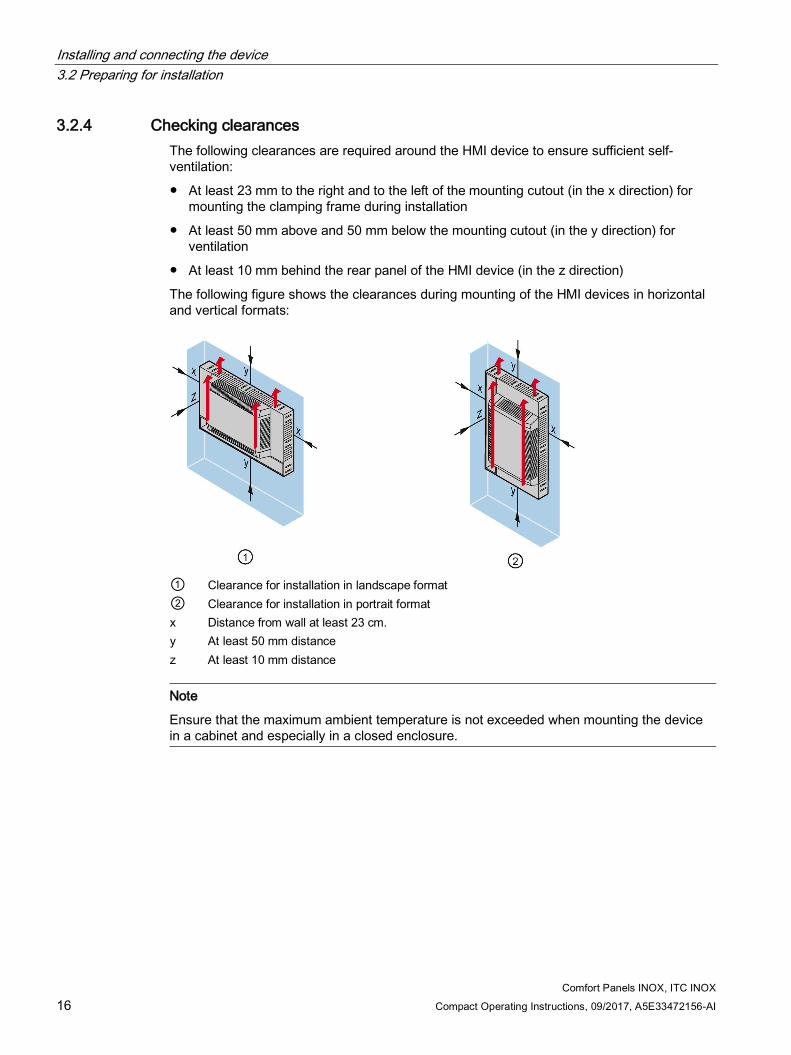
3.2.4 Checking clearances The following clearances are required around the HMI device to ensure sufficient self-ventilation:
● At least 23 mm to the right and to the left of the mounting cutout (in the x direction) for mounting the clamping frame during installation
● At least 50 mm above and 50 mm below the mounting cutout (in the y direction) for ventilation
● At least 10 mm behind the rear panel of the HMI device (in the z direction)
The following figure shows the clearances during mounting of the HMI devices in horizontal and vertical formats:
① Clearance for installation in landscape format ② Clearance for installation in portrait format x Distance from wall at least 23 cm. y At least 50 mm distance z At least 10 mm distance
Note
Ensure that the maximum ambient temperature is not exceeded when mounting the device in a cabinet and especially in a closed enclosure.

Installing and connecting the device 3.3 Inserting the mounting gasket
Comfort Panels INOX, ITC INOX Compact Operating Instructions, 09/2017, A5E33472156-AI 17
3.3 Inserting the mounting gasket The following process describes the use of the mounting gasket for all devices based on the example of the TP700 Comfort INOX.
The mounting gasket is unsymmetrical and is therefore equipped with a coding tap.
On all mounting gaskets of the INOX devices, the coding tap is on the bottom left in relation to the rear of the device.
① Seal rounding ② Retaining collar ③ Coding tap
Procedure
Note
Use a new mounting gasket, otherwise the degree of protection specified in the compact operating instructions cannot be guaranteed.
1. Find the coding tap on the mounting gasket and rotate the mounting gasket as shown in the figure below.

Installing and connecting the device 3.3 Inserting the mounting gasket
Comfort Panels INOX, ITC INOX 18 Compact Operating Instructions, 09/2017, A5E33472156-AI
2. Place the mounting gasket as shown on the stainless steel face.
① Seal rounding lies below the housing frame ② Sealing clamp locks fully into the cutout ③ Coding tap
3. Check the correct fit of the mounting gasket.
The coding tap must be positioned at the location indicated. The round sections of the seal and the seal clamps must lie in the cutouts specified for this purpose. If the mounting gasket was inserted correctly, it lies flat and without warping on the stainless steel face.
The edge of the mounting gasket closes flush with the edge of the stainless steel face.

Installing and connecting the device 3.4 Positions of the mounting clips for TP1900 Comfort INOX and ITC1900 INOX
Comfort Panels INOX, ITC INOX Compact Operating Instructions, 09/2017, A5E33472156-AI 19
3.4 Positions of the mounting clips for TP1900 Comfort INOX and ITC1900 INOX
The following section describes how you can install the device. Observe the following mounting clip positions for the TP1900 Comfort INOX and the ITC1900 INOX:

Installing and connecting the device 3.5 Mounting the device
Comfort Panels INOX, ITC INOX 20 Compact Operating Instructions, 09/2017, A5E33472156-AI
3.5 Mounting the device The following process describes installation for all devices based on the example of the TP700 Comfort INOX.
Requirement ● All packaging components and the edge protection tape, if present, have been removed.
● 1 clamping frame
● 1 Allen key 2.5 mm
● Mounting clips:
– TP700 Comfort INOX: 10 mounting clips
– TP900 Comfort INOX: 13 mounting clips
– TP1200 Comfort INOX: 12 mounting clips
– TP1500 Comfort INOX: 20 mounting clips
– TP1900 Comfort INOX, ITC1900 INOX: 18 mounting clips

Installing and connecting the device 3.5 Mounting the device
Comfort Panels INOX, ITC INOX Compact Operating Instructions, 09/2017, A5E33472156-AI 21
Installation 1. Assemble the device with inserted mounting gasket, clamping frame and all supplied
mounting clips as shown in the figure below. Observe the additional product information, if any, supplied with the product.
The tip of the setscrew must be inserted into the center hole as shown in the zoomed section of the figure.
Material thickness t at the mounting cutout:
TP700/900/1200 Comfort INOX: 1.5 ... 6 mm TP1500/1900 Comfort INOX and ITC1900 INOX: 1.5 ... 5 mm
2. Turn the setscrew of each mounting clip until a slight clamping force is perceptible. After a few rotations a slight resistance will become perceptible. When the increase in force is perceptible, tighten the setscrew of the next mounting clip. Perform this step for all setscrews.
3. Check the correct placement of the mounting gasket. The edge of the mounting gasket must be flush and close evenly with the stainless steel face; it may project 0.1 to 0.5 mm.
4. Tighten the setscrew of the mounting clip until the fixed stop is reached and the torque increases perceptibly. The tightening torque is then:
– Approx. 1.0 Nm with 7", 9" and 12" devices
– Approx. 0.5 Nm with 15" and 19" devices
The stainless steel front lies fully against the installation location and the mounting gasket is subject to required clamping force.
5. Check that the fixed stop has been reached on all mounting clips and that the mounting gasket is installed correctly. Correct the tightening torque, if necessary, so that the clamping force is evenly distributed.
Removal For removal, follow the steps for installation in reverse order. Dispose of the used mounting gasket.

Installing and connecting the device 3.6 Connecting the device
Comfort Panels INOX, ITC INOX 22 Compact Operating Instructions, 09/2017, A5E33472156-AI
3.6 Connecting the device The specifications in the relevant operating instructions apply.
Please also note the following information.
Connection in hazardous areas
WARNING
Explosion hazard
The audio connectors are only designed for temporary connection.
Do not use, connect or disconnect until the device is in a non-hazardous area.
Connecting or disconnecting in a hazardous environment could cause an explosion.
Securing cables After connecting the USB cables, secure them to the corresponding fixing elements using the cable ties.
Comfort Panels INOX, ITC INOX Compact Operating Instructions, 09/2017, A5E33472156-AI 23
Cleaning the device 4 4.1 Cleaning product
The specifications in the operating instructions apply when using the device in hazardous areas of Zones 2 and 22.
For use of the device at normal atmospheric conditions, the following is permitted in addition to the operating instructions:
● Cleaning with strong jet water under increased pressure
On front IP66K in accordance with DIN 40050, Part 9
4.2 Clean screen for Touch HMI devices This chapter is valid for the Comfort INOX HMI devices.
The touch screen of the HMI device can be cleaned when it is switched on and a project is running. An operating element must be available in the project that can be used to call the "clean" screen. Once the clean screen is activated, touch screen operation is locked for a configured period of time. The time the touch screen is locked can be set between 5 and 30 seconds. The time remaining for the lockout is indicated by a progress bar.
Note Unintentional responses
When cleaning the touch screen, an unintentional response in the controller can be triggered by touching keys.
Always open the clean screen or switch off the HMI device before you clean the touch screen while the system is running. Cannot be operated when the clean screen is active
When the clean screen is active, operations on the HMI device are not possible.
Wait for the period of the clean screen to lapse. Then you can operate the system again with the HMI device. No clean screen with HMI devices with touch screen and function keys
The clean screen is not available for HMI devices with touch screen and function keys. In this case, configure a screen without operating elements, for example.

Cleaning the device 4.3 Chemical Resistance
Comfort Panels INOX, ITC INOX 24 Compact Operating Instructions, 09/2017, A5E33472156-AI
4.3 Chemical Resistance
Front membrane The resistance of the front membrane to various chemicals has been tested to DIN 42 115, section 2. The front membrane is resistant to the chemicals listed below:
● Alcohol
● Diluted acids
● Diluted caustic solutions
● Ester
● Hydrocarbons
● Household cleaners
You can find information of chemical resistance on the Internet (http://support.automation.siemens.com/WW/view/en/39718396).
Mounting gasket The mounting gasket made of EPDM is approved for food according to FDA 21 CFR 177-2600.
4.4 Working with stainless steel surfaces
Resistance Information on the resistance of stainless steel:
● The stainless steel surface is not fully resistant against the chemicals listed below:
– Hydrochloric acid
– Sulphuric acid
– Sodium hydroxide
– Chlorine
– Chlorides
Do not clean the stainless steel surface with these chemicals or with similar acids or caustic solutions.
● Acid steam develops, for example, when tiles are cleaned with hydrochloric acid, and is also harmful to the stainless steel. If the stainless steel parts are unintentionally contaminated with hydrochloric acid, rinse these off immediately with plenty of water.
● Clean the stainless steel surface with a cleansing agent without active chlorine.
Cleaning the device 4.4 Working with stainless steel surfaces
Comfort Panels INOX, ITC INOX Compact Operating Instructions, 09/2017, A5E33472156-AI 25
Cleaning guidelines Further information on stainless steel surfaces:
● The surface should be properly ventilated.
● Keep the surface clean. Remove cleaners and food residue immediately. Always avoid the return of food stuff splashes to the production process.
● If mechanical cleaning is necessary, do not use cleaning equipment made of metal.
– Use brushes made of plastic or natural materials, or a microfiber pad.
– Use plenty of water to clean the surface.
– Make sure that the cleansing agent is completely removed without any residue.
● Make sure surface is not damaged: Do not damage the device during operation, or by cleaning or repairing it using hard tools, in particular tools made of corrodible materials.
● Make sure that the surface does not come into contact with rusted parts.
This includes water pipes, filings, residue from wire brushes or steel wool. These, as well as rust films have a corrosive effect on parts made of stainless steel.
– Remove any stains or rust immediately.
– Remove new rust spots with a mild abrasive detergent in order to prevent any further corrosion.
– Rinse the part thoroughly after you cleaned it.

Comfort Panels INOX, ITC INOX 26 Compact Operating Instructions, 09/2017, A5E33472156-AI
Technical specifications 5 5.1 Certificates and approvals
Approvals
Note
The following overview shows possible approvals.
The HMI device itself is approved as shown on the rear panel labels.
CE approval The HMI device meets the general and safety-related requirements of the following EU directives and conforms to the harmonized European standards (EN) for programmable logic controllers published in the official gazettes of the European Union:
● 2014/30/EU "Electromagnetic Compatibility" (EMC Directive)
● 2014/34/EU "Equipment and protective systems for use in hazardous areas" (Explosion protection directive)
● 2011/65/EU "Directive of the European Parliament and of the Council of 8 June 2011 on the restriction of the use of certain hazardous substances in electrical and electronic equipment" (RoHS Directive)
EU Declaration of Conformity
The EU Declarations of Conformity are available to the relevant authorities at the following address:
Siemens AG Digital Factory Factory Automation DF FA AS SYS P.O. Box 1963 D-92209 Amberg, Germany
The declaration of conformity and additional certificates are also available at the following Internet address:INOX HMI devices certificates (https://support.industry.siemens.com/cs/ww/en/ps/14830/cert)
IEC 61131 The HMI device satisfies the requirements and criteria conforming to IEC 61131-2, Programmable Logic Controllers, Part 2: Equipment requirements and tests.

Technical specifications 5.1 Certificates and approvals
Comfort Panels INOX, ITC INOX Compact Operating Instructions, 09/2017, A5E33472156-AI 27
UL approval Underwriters Laboratories Inc., to
● UL 508 (Industrial Control Equipment)
● CSA C22.2 No. 142 (Process Control Equipment)
or
Underwriters Laboratories Inc., to
● UL 508 (Industrial Control Equipment)
● CSA C22.2 No. 142 (Process Control Equipment)
● UL 1604 (Hazardous Location)
● CSA-213 (Hazardous Location)
Approved for use in
● Class I, Division 2, Group A, B, C, D or
● Class I, Zone 2, Group IIC or
● non-hazardous locations
FM Approval Factory Mutual Research (FM) conforming to
● Approval Standard Class Number 3611, 3600, 3810
● CSA C22.2 No. 213
● CSA C22.2 No. 1010.1
Approved for use in
● Class I, Division 2, Group A, B, C, D T4
● Class I, Zone 2, Group IIC T4

Technical specifications 5.1 Certificates and approvals
Comfort Panels INOX, ITC INOX 28 Compact Operating Instructions, 09/2017, A5E33472156-AI
ATEX/IECEx approval
WARNING
Personal injury or material damage due to inobservance of safety instructions
Inobservance of safety instructions valid for your device may result in personal injury or material damage.
The information in the attached "Use in potentially explosive atmosphere, zone 2 and 22" section of the "Use in Potentially Explosive Atmosphere, Zones 2 and 22" product information (identification number A5E02095382) is valid for the INOX devices listed in this Compact Operating Instructions manual.
Observe the information in this Compact Operating Instructions manual and in the "Use in Potentially Explosive Atmosphere, Zones 2 and 22" product information (identification number A5E02095382) included with your device and is available on the Internet at the following address: ATEX-FAQ (https://support.industry.siemens.com/cs/ww/en/view/291285) Operating temperature for ITC1900 INOX, TP1900 Comfort INOX
The ambient temperature range is 0 °C ≤ T ≤ 45 °C. Under these conditions, the HMI device satisfies a maximum surface temperature of xx °C for category 3D (xx = Temperature values, see design examination certificate (https://support.industry.siemens.com/cs/ww/en/ps/14830/cert)).
Special conditions of use
The front side of the SIMATIC Comfort INOX device or the SIMATIC ITC1900 INOX device provides a degree of protection of at least IP65. It shall be installed in a suitable enclosure providing a degree of protection of at least IP54 according to EN 60079-15 for gas and non-conductive dust and IP6X according to EN 60079-31 for conductive dust, taking into account the environmental conditions under which the equipment is used.
The equipment shall be installed in such a way that the risk of mechanical danger is low.
To avoid an electrostatic charge, wipe the enclosure surface with a damp cloth only.
When used in an area requiring the use of equipment with EPL Gc:
● The equipment shall only be used in an area of not more than pollution degree 2, as defined in EN 60664-1.
● Provisions shall be made to prevent the rated voltage from being exceeded by transient disturbances of more than 119 V.

Technical specifications 5.1 Certificates and approvals
Comfort Panels INOX, ITC INOX Compact Operating Instructions, 09/2017, A5E33472156-AI 29
Under the special conditions mentioned, the following approvals apply to the device:
● II 3 G Ex nA IIC T4 Gc and
II 3 D Ex tc IIIC T70 ºC Dc IP65
ATEX certificate number:
– TP700/1200 Comfort INOX: DEKRA 11 ATEX 0005 X
– TP900/1500/1900 Comfort INOX, ITC1900 INOX: DEKRA 15 ATEX 0074 X
Standards: EN 60079-0:2012 +A11:2013, EN 60079-15:2010, EN 60079-31:2014
● Ex nA IIC T4 Gc and
Ex tc IIIC T70 ºC Dc
IECEx certificate number:
– TP700/1200 Comfort INOX: DEK 13.0085 X
– TP900/1500/1900 Comfort INOX, ITC1900 INOX: DEK 15.0049 X
Standards: IEC 60079-0:2011 (Ed.6), +Corr.1. 2012 +Corr.2. 2013, IEC 60079-15:2010 (Ed. 4), IEC 60079-31:2013 (Ed. 2)
RCM Declaration of Conformity for Australia/New Zealand This product meets the requirements of the standards:
● AS/NZS 61000.6.4
● IEC 61000-6-4
KOREA This product meets the requirements of Korean certification.
This product satisfies the requirement of the Korean Certification (KC Mark).
이 기기는 업무용(A급) 전자파 적합기기로서 판매자 또는 사용자는 이 점을 주의하시기 바라며 가정 외의 지역에서 사용하는 것을 목적으로 합니다.
Note that this device conforms to Limit Class A for emission of radio interference. This device can be used in all areas except the residential area.
Identification for Eurasion Customs Union ● EAC (Eurasian Conformity)
● Customs union of Russia, Belarus and Kazakhstan
● Declaration of conformity according to Technical Regulations of the Customs Union (TR CU)
WEEE label (European Union) Disposal notice, observe the local regulations and the section "Recycling and disposal" of the Operating Instructions.

Technical specifications 5.2 Dimension drawings
Comfort Panels INOX, ITC INOX 30 Compact Operating Instructions, 09/2017, A5E33472156-AI
Marine approvals The marine approvals for the device are listed in the following product information: Comfort Panels INOX, ITC INOX Marine approvals (https://support.industry.siemens.com/cs/ww/en/ps/14830/man)
5.2 Dimension drawings
5.2.1 Dimension drawing TP700 Comfort INOX
Clamping frame

Technical specifications 5.2 Dimension drawings
Comfort Panels INOX, ITC INOX Compact Operating Instructions, 09/2017, A5E33472156-AI 31
5.2.2 Dimension drawing TP900 Comfort INOX
Clamping frame

Technical specifications 5.2 Dimension drawings
Comfort Panels INOX, ITC INOX 32 Compact Operating Instructions, 09/2017, A5E33472156-AI
5.2.3 Dimension drawing TP1200 Comfort INOX
Clamping frame

Technical specifications 5.2 Dimension drawings
Comfort Panels INOX, ITC INOX Compact Operating Instructions, 09/2017, A5E33472156-AI 33
5.2.4 Dimension drawing TP1500 Comfort INOX
Clamping frame

Technical specifications 5.2 Dimension drawings
Comfort Panels INOX, ITC INOX 34 Compact Operating Instructions, 09/2017, A5E33472156-AI
5.2.5 Dimension drawing TP1900 Comfort INOX, ITC1900 INOX
Clamping frame

Technical specifications 5.3 Technical specifications
Comfort Panels INOX, ITC INOX Compact Operating Instructions, 09/2017, A5E33472156-AI 35
5.3 Technical specifications
Weight Device Weight including clamping frame, gasket and mounting
clips, without packaging TP700 Comfort INOX approx. 1.9 kg TP900 Comfort INOX approx. 2.5 kg TP1200 Comfort INOX approx. 3.6 kg TP1500 Comfort INOX approx. 6.6 kg TP1900 Comfort INOX, ITC1900 INOX approx. 8.8 kg
Material Component Material Front frame Stainless steel, material number 1.4301, V2A Front membrane Polyester-based Mounting gasket EPDM, 70 Shore A, black
Protection class and degree of protection Characteristic Standard Classification Protection class EN 61131-2 Protection class III Degree of protection, on the front, for operation at normal atmospheric conditions
EN 60529:1991 + A1:2000 and DIN 40050-9
IP66K
Degree of protection, on the front, for operation in hazardous areas of Zones 2 and 22
See section "Certificates and approvals (Page 26)", "ATEX/IECEx approval" paragraph.
TP700 Comfort INOX, TP1200 Comfort INOX: IP66K TP900 Comfort INOX, TP1500 Comfort INOX, TP1900 Comfort INOX, ITC1900 INOX: IP65
Degree of protection, rear
EN 60529 IP20
Enclosure Type, Front face only
UL50 TP700 Comfort INOX, TP1200 Comfort INOX, TP1900 Comfort INOX, ITC1900 INOX: Type 4X (indoor use only) TP900 Comfort INOX, TP1500 Comfort INOX, Type 4X/Type 12 (indoor use only)
Note that the information on "enclosure type" is only guaranteed if the mounting cutout conforms to the following: ● The device has been installed according to the information provided in this document. ● Material thickness at the mounting cutout:
– TP700/900/1200 Comfort INOX: 1.5 ... 6 mm – TP1500/1900 Comfort INOX and ITC1900 INOX 1.5 ... 5 mm
● Permitted deviation from plane at the mounting cutout: ≤ 0.5 mm This condition must be fulfilled even for the mounted device.
● Permitted surface roughness in the area of the mounting gasket: ≤ 120 µm, corresponds to Rz 120

Technical specifications 5.4 Classification of environmental conditions
Comfort Panels INOX, ITC INOX 36 Compact Operating Instructions, 09/2017, A5E33472156-AI
5.4 Classification of environmental conditions
5.4.1 Overview The standards of the IEC 60721 series can be used to classify short-term extreme environmental conditions that can occur during the service life of a product. Structurally, the product is designed in such a way that it can withstand the extreme environmental conditions according to the classification.
The following chapters provide you with information on the classification of the environmental conditions for the device:
● Long-term storage and transport
● Stationary and weather-protected use
5.4.2 Classification for storage This device exceeds requirements according to IEC 61131-2:2007 "Programmable controllers – Part 2: Equipment requirements and tests" in terms of valid environmental conditions. The following classes apply to the device when stored in the original packaging.
● Mechanical environmental conditions
Standard Title IEC 61131-2:2007 Programmable logic controllers – Part 2:
Equipment requirements and tests
● Climatic environmental conditions
Standard Title IEC 60721-3-1:1997 Classification of groups of environmental parameters and their severities –
Section 1: Storage Class 1K1 applies with the following expansions: • Temperature ranges:
– TP700/900 Comfort INOX: –20 … 60 °C – TP1200 Comfort INOX: –20 … 55 °C – TP1500 Comfort INOX: –20 … 50 °C – TP1900 Comfort INOX: –20 … 45 °C
• Range of relative humidity: – TP700/900 Comfort INOX: 10 … 90% – TP1200/1500 Comfort INOX: 10 … 80% – TP1900 Comfort INOX, ITC1900 INOX: 10 … 70%
The tests relevant for the specified classes correspond to the tests for classification of shipping. The testing of the device was performed in the original packing.

Technical specifications 5.4 Classification of environmental conditions
Comfort Panels INOX, ITC INOX Compact Operating Instructions, 09/2017, A5E33472156-AI 37
5.4.3 Classification for shipping This device exceeds requirements according to IEC 61131-2:2007 "Programmable controllers – Part 2: Equipment requirements and tests" in terms of valid environmental conditions.
The following specifications apply to the device when transported in the original packing.
● Mechanical environmental conditions
Standard Title IEC 61131-2:2007 Programmable logic controllers – Part 2:
Equipment requirements and tests
● Climatic environmental conditions
Standard Title IEC 60721-3-2:1997 Classification of groups of environmental parameters and their severities –
Section 2: Transportation Class 2K1 applies with the following extensions: • Temperature ranges:
– TP700/900 Comfort INOX: –20 … 60 °C – TP1200 Comfort INOX: –20 … 55 °C – TP1500 Comfort INOX: –20 … 50 °C – TP1900 Comfort INOX, ITC1900 INOX: –20 … 45 °C
• Range of relative humidity: – TP700/900 Comfort INOX: 10 … 90% – TP1200/1500 Comfort INOX: 10 … 80% – TP1900 Comfort INOX, ITC1900 INOX: 10 … 70%
The following specifications apply to the device when transported in the original packing.
The following values are derived for the significant tests from the classes stated. The testing of the device was performed in the original packing. Test Value Comment Free fall EN 60068-2-32
1 m 5 × free fall, in shipping packaging
Temperature EN 60068-2-1, test Ab and EN 60068-2-2, test Bb
–20 to +60 °C Cold and dry heat
Air pressure; IEC 60068-2-13
1140 to 660 hPa Corresponds to an altitude of –1000 to 3500 m
Humidity, relative • TP700/900 Comfort INOX: 10 … 90% • TP1200/1500 Comfort INOX: 10 … 80% • TP1900 Comfort INOX, ITC1900 INOX:
10 … 70%
No condensation
Shock; IEC 60068-2-27
250 m/s2, 6 ms 1000 shocks

Technical specifications 5.4 Classification of environmental conditions
Comfort Panels INOX, ITC INOX 38 Compact Operating Instructions, 09/2017, A5E33472156-AI
Tests for mechanical environmental conditions in the transport packaging The following table shows the type and scope of the tests of the device with regard to mechanical environmental conditions. Test Physical variable Value Vibration test IEC 60068-2-6:2007-12 Test Fc
Vibration 3 axes, 10 cycles per axis Frequency change: 1 octave / min
Frequency range 5 to 8.4 Hz deflection 3.5 mm 8.4 to 150 Hz vibration acceleration 9.8 m/s2
Shock duration test IEC 60068-2-27:2008-02 Test Ea
Shock form half-sine Acceleration 25 g Shock duration 6 ms Number of shocks 1000 shocks in each of the three mutually
vertical axes.
Tests for climatic environmental conditions in the transport packaging The following table shows the type and scope of the tests of the device with regard to climatic environmental conditions. Environmental condition Physical variable Value Cold test EN 60068-2-1:2007-03 Test Ab
Temperature –20 °C Duration 16 h Rate of temperature change 20 K/h
Warm test, dry EN 60068-2-2:2007-07 Test Bb
Temperature 60 °C Duration 16 h Rate of temperature change 20 K/h
5.4.4 Classification for stationary and weather-protected use The following classes apply when the device is operated.
● Mechanical environmental conditions
Standard Title IEC 60721-3-3:1997 Classification of groups of environmental parameters and their severities –
Section 3: Stationary use at weatherprotected locations Class 3M3 applies.
● Climatic environmental conditions
Standard Title IEC 60721-3-3:1994 Classification of groups of environmental parameters and their severities –
Section 3: Stationary use at weatherprotected locations Class 3K3 applies.
The following values are derived for the significant tests from the classes stated. The testing of the device was performed without original packing.

Technical specifications 5.4 Classification of environmental conditions
Comfort Panels INOX, ITC INOX Compact Operating Instructions, 09/2017, A5E33472156-AI 39
Ambient temperature during operation Type of condition Mounting position Permissible range Temperature, Installation in horizontal format
Vertical 0 ... 50 °C 1 inclined, incline max. 35 0 ... 40 °C
Temperature, Installation in portrait format
Vertical 0 ... 40 °C inclined, incline max. 35 0 ... 35 °C
1 TP1900 Comfort INOX and ITC1900 INOX: 0 ... 45 °C 2 No pressure difference inside and outside of the enclosure/control cabinet permitted
Humidity and atmospheric pressure during operation Test Value, range Comment Humidity
• TP700/TP900 Comfort INOX 10 ... 90% No condensation
• TP1200/1500 Comfort INOX 10 ... 80% No condensation
• TP1900 Comfort INOX, ITC1900 INOX
10 ... 70% No condensation
Atmospheric pressure 1 1140 to 795 hPa Corresponds to an altitude of -1000 m to 2000 m
1 No pressure difference inside and outside of the enclosure/control cabinet permitted
Observe the Notes on use (Page 12).
In addition, observe the climate diagram in the following section and the information on the extended inclination and ambient temperature range, see section "Selecting a mounting position (Page 14)".
Note
System components connected to the HMI device, such as the power supply, must also be suitable for operation under the corresponding rated conditions.
Tests for mechanical environmental conditions during operation The following table shows the type and scope of the tests of the device with regard to mechanical environmental conditions. Test Physical variable Value Vibration test IEC 60068-2-6:2007-12 Test Fc
Vibration 3 axes, 10 cycles per axis Frequency change 1 octave/min
Frequency range 5 to 8.4 Hz, deflection 3.5 mm 8.4 to 200 Hz, vibration acceleration 9.8 m/s2
Shock test IEC 60068-2-27:2008-02 Test Ea
Shock form half-sine Acceleration 15 g Shock duration 11 ms Number of shocks 3 per axis in positive and negative direction

Technical specifications 5.4 Classification of environmental conditions
Comfort Panels INOX, ITC INOX 40 Compact Operating Instructions, 09/2017, A5E33472156-AI
Test Physical variable Value Fall EN 60068-2-31:2009 Test Ec
Fall height 1.0 m Number of strains 5
Tests for climatic environmental conditions during operation The following table shows the type and scope of the tests of the device with regard to climatic environmental conditions. Environmental condition Physical variable Value Cold test EN 60068-2-1:2007-03 Test Ad
Temperature 0 °C Duration 16 h Speed of the temperature change 10 K/h
Warm test, dry EN 60068-2-2:2007-07 Test Bd
Temperature
• TP700/900/1200/1500 Comfort INOX 50 °C
• TP1900 Comfort INOX, ITC1900 INOX 45 °C
Duration 96 h Speed of the temperature change 10 K/h
5.4.5 Climate diagram The diagram below shows the extended range for temperature and humidity in uninterrupted duty based on IEC 60721-3-3 class 3K3 using the TP700/TP900 Comfort INOX as an example. Information on the maximum permitted humidity of the other devices is available in the section "Classification for stationary and weather-protected use (Page 38)".
The information applies to a device installed in landscape without inclination.
Red: Extended temperature range of 7-15" devices; see section "Selecting a mounting position (Page 14)".

Comfort Panels INOX, ITC INOX Compact Operating Instructions, 09/2017, A5E33472156-AI 41
Technical Support A A.1 Service and support
You can find additional information and support for the products described on the Internet at the following addresses:
● Technical support (https://support.industry.siemens.com)
● Support request form (http://www.siemens.com/automation/support-request)
● After Sales Information System SIMATIC IPC/PG (http://www.siemens.com/asis)
● SIMATIC Documentation Collection (http://www.siemens.com/simatic-tech-doku-portal)
● Your local representative (http://www.automation.siemens.com/mcms/aspa-db/en/Pages/default.aspx)
● Training center (http://sitrain.automation.siemens.com/sitrainworld/?AppLang=en)
● Industry Mall (https://mall.industry.siemens.com)
When contacting your local representative or Technical Support, please have the following information at hand:
● MLFB of the device
● BIOS version for industrial PC or image version of the device
● Other installed hardware
● Other installed software
Tools & downloads Please check regularly if updates and hotfixes are available for download to your device. The download area is available on the Internet at the following link:
After Sales Information System SIMATIC IPC/PG (http://www.siemens.com/asis)

Comfort Panels INOX, ITC INOX 42 Compact Operating Instructions, 09/2017, A5E33472156-AI
List of abbreviations B
DC Direct Current ESD Components and modules endangered by electrostatic discharge EMC Electromagnetic Compatibility EN European standard FDA Food and Drug Administration GND Ground HF High Frequency IEC International Electronic Commission IP Internet Protocol LED Light Emitting Diode TFT Thin Film Transistor UL Underwriter’s Laboratory USB Universal Serial Bus