Microstructure based effective stress formulation for partially ...
39
Microstructure based effective stress formulation for partially saturated granular soils K.N. Manahiloh 1 , B. Muhunthan 2 , and W.J. Likos 3 Abstract The principle of effective stress states that the strength and volume change behaviors of soil are governed by intergranular forces expressed in terms of a continuum quantity called effective stress. Although the principle of effective stress is regarded as one of the most fundamental concepts in soil mechanics, its applicability to partially saturated soil has been debated. The central issue is whether a measure can be developed for three-phase soils that plays an equivalent role as the effective stress does in two-phase soils. This study attempts to forward such a measure by incorporating soil microstructure in the effective stress formulation. A novel suction- controlled experimental setup is developed and integrated with an X-ray CT scanning system to image and model microstructural features. A tensorial quantity, called fabric tensor of the liquid phase, that characterizes the complex fabric resulting from saturated pockets and networks of liquid bridges is identified and introduced in the proposed formulation. It is shown that fabric tensor of the liquid phase varies randomly, in both the wetting and drying phases of the partial saturation, and has an intrinsic association with the evolution of the effective stress tensor. It is also shown that this random variation can be depicted by applying techniques of digital image processing. It is concluded that, for partially saturated granular soils, the consideration of fabric tensor of the liquid phase in effective stress formulations is imperative. Keywords: Partial saturation, granular soil, effective stress, virtual work, soil fabric, fabric tensor, microstructure, soil suction, degree of saturation, X-ray computed tomography (X-ray CT), image processing, soil water retention curve (SWRC) Citation Information: Please cite this work as follows Manahiloh Kalehiwot, N., B. Muhunthan, and J. Likos William, Microstructure-Based Effective Stress Formulation for Unsaturated Granular Soils. International Journal of Geomechanics, 2016. 16(6). Official publication link: https://ascelibrary.org/doi/10.1061/%28ASCE%29GM.1943-5622.0000617 1 A.M. ASCE, Ph.D., Assistant Professor, Department of Civil & Environmental Engineering, University of Delaware, 301 DuPont Hall, Newark, DE 19716, E-mail: [email protected] 2 F. ASCE, Ph.D., P.E., Professor, Department of Civil & Environmental Engineering, Washington State University, 405 Spokane St., Sloan Hall 30, Pullman, WA 99164, e-mail: muhuntha@wsu.edu 3 M. ASCE, Ph.D., Associate Professor, Department of Civil & Environmental Engineering, University of Wisconsin-Madison, 2215 Engineering Hall, Madison, WI 53706, e-mail: likos@wisc.edu
-
Upload
khangminh22 -
Category
Documents
-
view
1 -
download
0
Transcript of Microstructure based effective stress formulation for partially ...

Microstructure based effective stress formulation for partially
saturated granular soils
K.N. Manahiloh1, B. Muhunthan2, and W.J. Likos3
Abstract
The principle of effective stress states that the strength and volume change behaviors of soil are governed by intergranular forces expressed in terms of a continuum quantity called effective stress. Although the principle of effective stress is regarded as one of the most fundamental concepts in soil mechanics, its applicability to partially saturated soil has been debated. The central issue is whether a measure can be developed for three-phase soils that plays an equivalent role as the effective stress does in two-phase soils. This study attempts to forward such a measure by incorporating soil microstructure in the effective stress formulation. A novel suction-controlled experimental setup is developed and integrated with an X-ray CT scanning system to image and model microstructural features. A tensorial quantity, called fabric tensor of the liquid phase, that characterizes the complex fabric resulting from saturated pockets and networks of liquid bridges is identified and introduced in the proposed formulation. It is shown that fabric tensor of the liquid phase varies randomly, in both the wetting and drying phases of the partial saturation, and has an intrinsic association with the evolution of the effective stress tensor. It is also shown that this random variation can be depicted by applying techniques of digital image processing. It is concluded that, for partially saturated granular soils, the consideration of fabric tensor of the liquid phase in effective stress formulations is imperative. Keywords: Partial saturation, granular soil, effective stress, virtual work, soil fabric, fabric tensor, microstructure, soil suction, degree of saturation, X-ray computed tomography (X-ray CT), image processing, soil water retention curve (SWRC) Citation Information: Please cite this work as follows Manahiloh Kalehiwot, N., B. Muhunthan, and J. Likos William, Microstructure-Based Effective Stress Formulation for Unsaturated Granular Soils. International Journal of Geomechanics, 2016. 16(6). Official publication link: https://ascelibrary.org/doi/10.1061/%28ASCE%29GM.1943-5622.0000617
1 A.M. ASCE, Ph.D., Assistant Professor, Department of Civil & Environmental Engineering, University of Delaware, 301 DuPont Hall, Newark, DE 19716, E-mail: [email protected] 2 F. ASCE, Ph.D., P.E., Professor, Department of Civil & Environmental Engineering, Washington State University, 405 Spokane St., Sloan Hall 30, Pullman, WA 99164, e-mail: [email protected] 3 M. ASCE, Ph.D., Associate Professor, Department of Civil & Environmental Engineering, University of Wisconsin-Madison, 2215 Engineering Hall, Madison, WI 53706, e-mail: [email protected]

2
Introduction
Terzaghi’s principle of effective stress for saturated soils is regarded as one of the fundamental
concepts in geotechnical practices and the marker for the birth of classical soil mechanics. This
principle assumes two-phase media whose mechanical and hydraulic behaviors are unified by the
effective stress (Terzaghi 1936).
'ij ij w ijuσ σ δ= − (1)
Where: σij, and 'ijσ are the total and effective stresses; and uwδij is the pore-water pressure.
For saturated soils, the validity of the effective stress principle has been experimentally
verified (e.g. Rendulic 1936; Bishop & Eldin 1950; Laughton 1955; Skempton 1961; Wood
2005). However, as can be inferred from Equation 1, Terzaghi’s effective stress principle does
not capture the full behavior of as soil becomes partially saturated. In partially saturated soils,
individual solid particles may be partially exposed to water and/or to air. Moreover in a state of
partial saturation fluid exists at differing pressures depending on the degree of saturation at
different locations throughout the soil microstructure. This variation in turn results in matric
suction tensor (ua – uw)δij: a phenomenon that directly influences the net forces acting at particle-
particle contacts.
Effective stress formulations for partially saturated soils
The study on the mechanical behavior of unsaturated soils, in relation to the effective stress, has
shown significant developments since the 1950s (Croney et al. 1958; Bishop 1959) and 1960s
(Lambe 1960; Aitchison 1961; Jennings 1961). Croney et al. (1958) suggested an effective stress
formulation for unsaturated soils in which the pore-water pressure in the Terzaghi's expression
for saturated soils is modified by a bonding factor β' as
' ' wij ij ijuσ σ β δ= − × (2)

3
Where 'ijσ and σij are the effective and total normal stresses. β' is a measure of the number of
bonds under tension effective in contributing to soil strength (Croney et al. 1958).
Bishop (1959) extended Terzaghi's unified effective stress principle to unsaturated soils by
describing the stress state as a function of the pore-air pressure (ua), pore-water pressure (uw) and
a parameter (χ) referred to as the “Bishop parameter” and related to the degree of saturation, S, of
the soil as
' ( )a a wij ij ij iju u uσ σ χδ δ= − + − (3)
Jennings (1961) outlined two methods of measuring χ by comparing the behavior of a soil
specimen under changes in externally applied pressure. Essentially similar experimental
approaches for the measurement of the factor χ, and thus the relationship between χ and S, were
suggested by other researchers (Bishop et al. 1960; Bishop & Donald 1961). The parameter χ
attains values of 1 and 0 for fully saturated and fully dry soil conditions respectively. On the
other hand, Coleman (1962) described χ as a parameter strongly related to the soil structure
rather than to volumetric parameters like the degree of saturation. Following Coleman’s
assertion, recent studies (e.g. Khalili & Khabbaz 1998 ; Khalili et al. 2004) related χ to the ratio
of soil matric potential to the air-entry value or the suction ratio. Lu and Likos (2004) referred to
the product χ(ua−uw)δij as the suction stress and regarded the Bishop’s effective stress approach
as a macroscale interpretation attempting to describe the microscale contribution of interparticle
pore-water menisci located between soil particles and physicochemical forces to the net
interparticle stress. Furthermore, Lu and Likos (2004) extended Bishop’s effective stress
formulation and gave tensorial representation of suction stress for isotropic and anisotropic soils
as Equations 4 and 5 respectively.
( )a w iju uχ δ− (4)

4
( )ij a w iju uχ δ− (5)
The validity of Bishop’s effective stress formulation for unsaturated soils over the whole
range of saturation was contested by Jennings and Burland (1962). They claimed, even though
the formulation is statically correct as indicated by Bishop and Donald (1961), it was not shown
that the soil behavior is unaffected by changes in (σa – ua)δij and χ(ua – uw)δij such that their sum
(= 'ijσ ) is constant. They also showed that attempts to link the stress and deformation behavior of
an unsaturated soil with a single-valued effective stress equation, as is the case of Bishop, have
resulted in limited success. They found out that oedometer and all-around compression tests
performed on unsaturated and saturated soils indicated no unique relationship between volume
change and effective stress for most soils.
Alternative forms, that use independent stress state variables, were proposed to capture the
mechanical and volumetric behavior of unsaturated soils (Coleman 1962; Aitchison 1973;
Fredlund & Rahardjo 1993; Houlsby 1997; Li 2003a; Berney et al. 2004). In such formulations,
constitutive relationships were implemented for soil structure and flow laws were applied for the
fluids to characterize unsaturated behavior. Many of the proposed relationships (Aitchison 1961;
Jennings 1961; Aitchison 1973; Richards 1985), incorporate a soil parameter in order to come up
with single-valued effective stress equations (i.e. one stress state variable). However,
experiments (Fredlund & Rahardjo 1993) have demonstrated that relationships derived from
measured soil properties do not turn out to be single-valued.
The problem with single-valued effective stress equations is that the effective stress will have
different magnitudes for different problems (volume change or shear strength), different stress
paths, and different soil types (Coleman 1962; Jennings & Burland 1962; Burland 1964). Even
though the use of more than one stress state variable is tacitly agreed up on by many researchers,

5
the minimum number of variables for the investigation of saturated and unsaturated behaviors
had been a topic of debate for many years (Zhang & Lytton 2006). (Coleman (1962); Burland
(1965); Matyas and Radhakrishna (1968); Barden et al. (1969); Brackley (1971); Fredlund and
Morgenstern (1977)) argue that it is important to use two or more stress state variables. Fredlund
and Morgenstern (1977), conducting null tests, suggested that the possible combinations of stress
state variables given by Equation 6 could be used in cases where the air pressure (ua), the pore-
pressure (uw), and the total stress (σ) are assumed as references respectively. Houlsby (1997)
illustrated the choice of stress variables as being arbitrary as long as corresponding strain
variables satisfy work conjugacy.
( ) and ( )( ) and ( )( ) and ( )
ij a ij a w ij
ij w ij a w ij
ij a ij ij w ij
u u uu u uu u
σ δ δ
σ δ δ
σ δ σ δ
− −
− − − −
(6)
Referring to the preceding discussion it can be said, no matter how the unsaturated behavior
is pictured, clear assumptions, scope descriptions and objectives must be put before further
analyses are carried out. In this respect, Houlsby (2004) stressed the importance of clear
assertions with regard to the specific aspect of mechanical behavior under investigation and he
highlighted the importance of separating the effective stress formulation in to two stages:
definition and hypothesis.
In general effective stress formulations suggested by past studies fall under the umbrella of:
the single variable effective stress of the Bishop's type; formulations that involve multiple
independent stress state variables (e.g. Fredlund & Rahardjo 1993); formulations that involve
critical state considerations (Alonso et al. 1987; Alonso et al. 1990; Toll 1990; Wheeler &
Sivakumar 1993, 1995; Vaunat et al. 2000); or formulations that combine unified effective stress
of the Bishop type with additional stress variables which are functions of parameters such as

6
suction, soil fabric and saturation (e.g. Li 2003a; Alonso et al. 2010). Nuth and Laloui (2008)
chronologically classified the evolution of effective stress formulations for unsaturated soils as
follows.
i. Bishop’s single effective stress of the form:
( ) ' ( )ij a ij a w ijij u u uσ σ δ χ δ− −+= (7)
ii. Independent stress variables with possible combinations:
( ) and ( )( ) and ( )( ) and ( )
ij a ij a w ij
ij w ij a w ij
ij a ij ij w ij
u u uu u uu u
σ δ δ
σ δ δ
σ δ σ δ
− −
− − − −
(8)
iii. Effective stress of the Bishop type combined with other stress state variables taking either
of the following forms:
' ( ) ( )
Form A: ( , )
ij ij a ij ij
ij r ij
u s
s S
σ σ δ µ δ
ξ ξ δ
− = +
= (9)
'2( ) ( , )
Form B: ( , )
ij ij a ij r ij
ij r ij
u s S
s S
σ σ δ µ δ
ξ ξ δ
− = +
= (10)
Where µ1 and µ2 are defined as functions of suction (s) and degree of saturation (Sr).
Successful implementation of unsaturated soil mechanics into engineering practices demands
better understanding of parameters that control unsaturated behavior. Equally important is to
understand how each parameter influences the volumetric or strength properties of the
unsaturated media. For example, better realization of matric suction and fabric (skeletal or pore-
fluid) enables better conceptualization of the bulk soil behavior. In this regard, understanding
and quantifying the evolution of the pore-water fabric for unsaturated soil with changes in
suction and saturation could help explain many of the anomalies that have plagued existing
unsaturated effective stress formulations (Jennings & Burland 1962; Nuth & Laloui 2008).

7
Ongoing work has indicated that models incorporating only net normal stress and matric
suction in their formulation are unlikely to fully capture all aspects (e.g. nonlinearity, hysteresis,
etc.) of unsaturated soil behavior. As suction, saturation, wetting direction, and intergranular
stress are all inherently coupled, formulations that include both suction and saturation in their
formulation are most likely to capture unsaturated soil behavior in a robust way. In this respect it
becomes imperative to understand and include the effects of suction and soil fabric in the
effective stress formulation. Incorporating suction and fabric, Li (2003a) followed the virtual
work principle and forwarded an effective stress formulation for unsaturated granular assemblies
at a microstructural level. This approach is direct and opens the window for consideration of
pore-fluid in the effective stress quantification. Because of the appropriateness of the
fundamental principles applied, the virtual work approach is followed in this paper. Slight
modifications are made while modeling the pore-water and attempts are made to support the
mathematical formulation with experimental results and digital image processing of the
microstructure from X-ray CT scanned images.
While we recognize that many problems in unsaturated soils involve fine grained soils and
that inclusion of physicochemical forces are imperative for a fuller description of their
mechanics, granular particles are specifically chosen to elicit the influence of fabric elements on
the effective stress tensor. Within the above scope, this study seeks to advance the applicability
of effective stress concepts for unsaturated soils with due regard to pore-fluid fabric and suction
contributions at a microstructural level. The particular objective of this paper is to integrate
microstructural features and measurements into a new effective stress formulation for
unsaturated granular soils.

8
Matric suction
In geotechnical engineering suction can be defined as a quantity that quantify the
thermodynamic potential of soil pore water relative to a reference potential of free water. Pore
water potential may be imparted by capillary, osmotic and short-range adsorption effects. In
granular assemblies, Figure 1, surface tension and interface curvature predominantly contribute
to suction. Assuming the concentration of solute remains constant throughout (i.e. negligible
osmotic contribution) the difference between water pressure (uw) and air pressure (ua), resulting
from the surface tension and net negative pore pressure, is generally referred to as matric suction.
In the absence of external load, the liquid bridge menisci (see Figure 1b) give rise to interparticle
interactions. Molenkamp and Nazemi (2003a) named the resulting tensor “effective suction
tensor”. In a more recent study by Li (2003b, 2007a, 2007b), the suction tensor was shown to
have a deviatoric part, that depends on the granular fabric, in addition to its isotropic part.
(a) (b)
Figure 1. (a) Regimes of soil water characteristic curve (SWCC) for partially saturated granular soil. (b) Meniscus between two granular particles (Fig. b modified from Gili 1988)

9
When granular materials are subjected to external loads, it is evident that granular fabric and
the liquid bridge network will change. This evolution affects the state of stress and
corresponding non-linear and hysteretic material behavior. Moreover, the wetting and suction
histories have effects on shear strength and volume change behaviors (Ho 1988; Rahardjo 1990;
Fredlund & Rahardjo 1993; Pereira 1996; Shuai F. 1996). Historically, suction was included in
the effective stress formulation since the works of Aitchison and Donald (1956).
Soil fabric
Fabric is defined as a term referring to parameters like size, shape and arrangement of the solid
particles, the organic inclusions and the associated voids (liquid or gas). Comprehensive
description of fabric and its effect on the state of stress in different saturation regimes can be
derived from micromechanics. Since early estimates of the liquid bridge force between
monosized smooth spheres (Fisher 1926), several researches have advanced solutions for
interactions between liquid bridges and rough rigid spheres or other geometries (Pietsch 1968;
Lian et al. 1993; Likos & Lu 2004). In this regard: two-particle models have been extended to
regular packings of isodiametral spheres to derive simple microstructural constitutive models for
unsaturated granular media (Biarez et al. 1993; Molenkamp & Nazemi 2003a; Hicher & Cheng
2008); and particle-based computational simulations have been used to explore bulk behavior of
unsaturated media for irregularly packed and polydisperse populations of spheres in 2-D and 3-D
(Jiang et al. 2004; El-Shamy & Groger 2008). While such models have advanced our
understanding of unsaturated soil microstructure and the applicability of effective stress
concepts, they lack support from direct observation and quantification of microstructural
features.

10
Mathematically, fabric had been defined (Scott 1963; Mitchell 1976; Muhunthan 1991) in a
number of ways and a number of researchers (e.g. Cowin & Satake 1978; Nemat-Nasser &
Mehrabadi 1983; Kanatani 1984, 1985) studied fabric tensor based on solid particles. An
interesting remark by Muhunthan (1991) was that defining tensor parameters on the void phase
of a partially saturated media has a potential of delivering a unified measure for all particulate
media. Moreover, the advent of industrial X-ray CT and its applicability to the scanning of
geomaterials has enabled distinct imaging of the solid, liquid and gas phases at a microstructural
level. In this study, statistical correlations applicable to solid particles are assumed to
appropriately describe directional quantities on the liquid phase.
Displacement field in granular assembly
In this section the displacement field, an important component in the formulation of the virtual
work, is derived. To do so consider two particles A and B, with centroids at XA and XB
respectively and touching at point C located at XC, in contact in a granular assembly as shown in
Figure 2. Let &AB BAi if f be the forces exerted by particles A and B on each other. Equilibrium
condition requires that
0AB BAi if f+ = (11)
Figure 2. Solid particles in contact

11
If, in the assembly under a state of equilibrium, there are n numbers of particles in contact with
particle A at point β representing the counter for the n contact points, we can write
10
nA
ifβ
β =
=∑ (12)
Total moment in the assembly of particles in contact with A can be described as
1 1( ) ( )
n nA A A A A A
i j j j i if x x f x xβ β β β
β β= =
− = −∑ ∑ (13)
Where, the moment contribution from each contact point is given by
( ) ( ) ( )AB AB A BA BA B C B Ai j j i j j i j j
Particle A Particle B
f x x f x x f x x− + − = −
(14)
Considering all particles in the assembly touching at contact point C and denoting the total
number of contact points in the assembly by N, the total moment may be written as
1 1( )
N NC B A C C
i j j i jC C
f x x f d= =
− =∑ ∑ (15)
Where, ( ) ( )A BC CB A Cj j jx x d r r− = = − is referred to as the branch vector and it connects the
centroid of particles A and B.
Consider a virtual displacement field which introduces the relative displacement Cij∆ of the
contact point C.
i.e. C CB CAij i iu u∆ = − (16)
Where and CA CBi iu u are displacements of the contact point C when viewed as belonging to particle
A and B respectively and written as
( )( )
CA A AC C Ai i ij j jCB B BC C Bi i ij j j
u u x xu u x x
ωω
= + − = + −
(17)
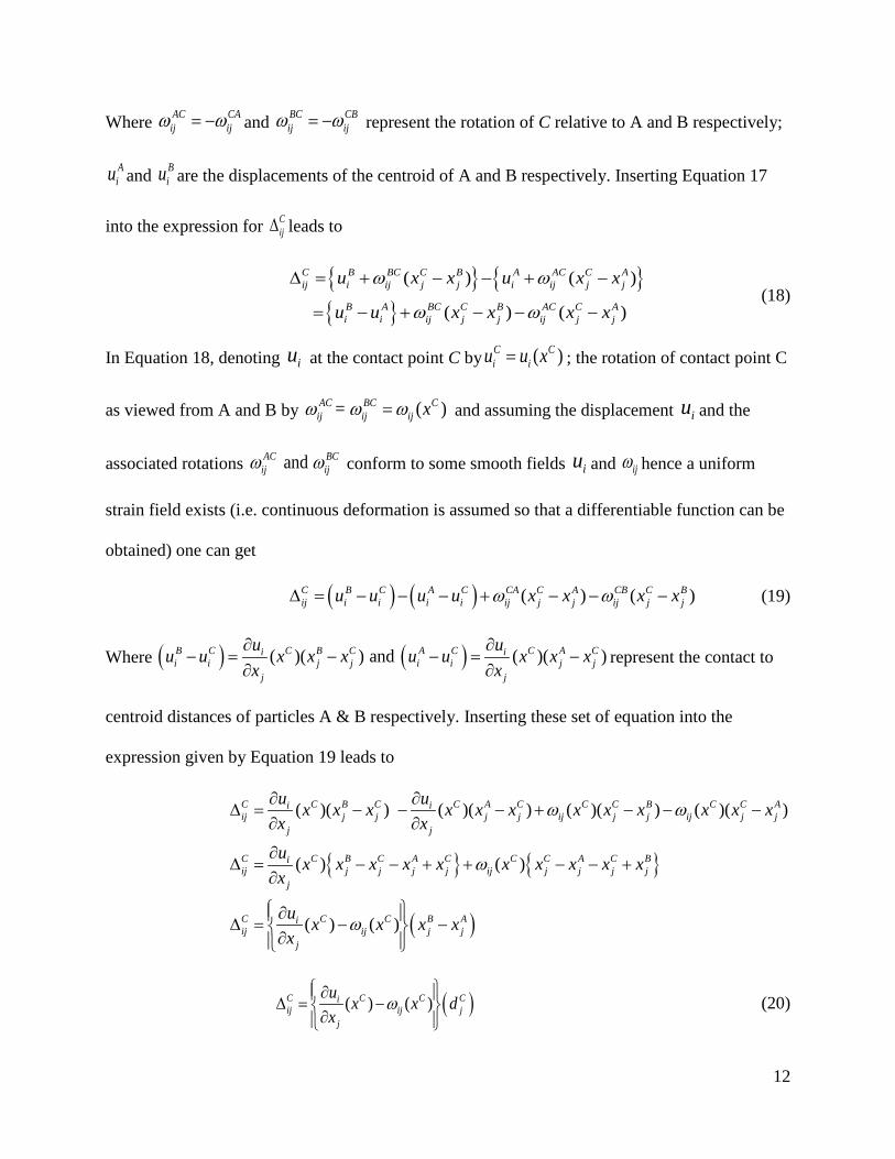
12
Where AC CAij ijω ω= − and BC CB
ij ijω ω= − represent the rotation of C relative to A and B respectively;
Aiu and B
iu are the displacements of the centroid of A and B respectively. Inserting Equation 17
into the expression for Cij∆ leads to
{ } { }{ }
( ) ( )
( ) ( )
C B BC C B A AC C Aij i ij j j i ij j j
B A BC C B AC C Ai i ij j j ij j j
u x x u x x
u u x x x x
ω ω
ω ω
∆ = + − − + −
= − + − − − (18)
In Equation 18, denoting iu at the contact point C by ( )C Ci iu u x= ; the rotation of contact point C
as viewed from A and B by = ( )AC BC Cij ij ij xω ω ω= and assuming the displacement iu and the
associated rotations and AC BCij ijω ω conform to some smooth fields iu and ijω hence a uniform
strain field exists (i.e. continuous deformation is assumed so that a differentiable function can be
obtained) one can get
( ) ( ) ( ) ( )C B C A C CA C A CB C Bij i i i i ij j j ij j ju u u u x x x xω ω∆ = − − − + − − − (19)
Where ( ) ( )( )( ) and ( )( )B C C B C A C C A Ci ii i j j i i j j
j j
u uu u x x x u u x x xx x
∂ ∂− = − − = −
∂ ∂represent the contact to
centroid distances of particles A & B respectively. Inserting these set of equation into the
expression given by Equation 19 leads to
{ } { }
( )
( )( ) ( )( ) ( )( ) ( )( )
( ) ( )
( ) ( )
C C B C C A C C C B C C Ai iij j j j j ij j j ij j j
j j
C C B C A C C C A C Biij j j j j ij j j j j
j
C C C B Aiij ij j j
j
u ux x x x x x x x x x x xx xu x x x x x x x x x xx
u x x x xx
ω ω
ω
ω
∂ ∂∆ = − − − + − − −
∂ ∂
∂∆ = − − + + − − +
∂
∂ ∆ = − − ∂
( )( ) ( )C C C Ciij ij j
j
u x x dx
ω ∂ ∆ = − ∂
(20)

13
Furthermore a linear boundary displacement can assumed in the uniform strain field such that
i ij j iu x cφ= + (21)
Where φij is an arbitrary second order constant tensor and ci is a constant vector. With this
assumption applied to Equation 20 it can be shown, to a first order of approximation, that the
displacement field is given by
( ) ( ),( ) ( )C C C C C Ciij ij j i j ijk k j ij j
j
u x x d u e d dx
ω ω φ ∂ ∆ = − = − + = ∂
(22)
The principle of virtual work
Virtual work principle is applied to relate contact forces to the overall stress in partially saturated
granular assemblies. To accomplish this, basic assumptions of: regarding soil skeleton as an
assembly of arbitrary rigid body particles in contact to each other; neglecting the effect of
microcouples produced at particle contacts; ignoring body forces; continuous displacement of
particles in an assembly during macroscopic deformation have been made. Referring to the
partially saturated granular assembly and its associated microstructural force system shown in
Figure 3, it can be said that virtual work can be done by three groups of forces in the
representative elementary volume (REV). The total virtual work done can be assumed to be the
sum of the work done by the paired internal contact forces fi and -fi; the boundary contact forces
if that result from direct contact with particles from other REV; and surface traction pi that
result from pore pressure ua or uw. Each component will be discussed in subsequent sections of
this paper.

14
Figure 3. The force system of a three-phase granular assembly
Virtual work done by internal contact forces: We have defined Cif and C
if− as the contact
forces exerted on particle A and B by each other at contact point C. And C Ci ij jdφ∆ = as indicated
in Equation 22 represents the virtual relative displacement at C. The virtual work done, by the
paired and opposite contact forces Cif and C
if− , is thus given as:
( )C C C Ci i ij i jf f dφ∆ = (23)
The total work done by all internal contact forces at particle “A” will then be the sum of all
contributions from each contact and this may be expressed as:
( ),1 1 1
N N NC C C C C Ci i ij i j i j ijk k i jf f u e fφ ω∆ = ∆ = − + ∆∑ ∑ ∑ (24)
Where N represents the total number of internal contact points of particle A with its neighbors.
Substituting the expression defined for Cj∆ into Equation 24 one may write the expression of
the work done by all internal contact forces in the granular assembly as
{ } ( ),1 1 1 1 1 1
( ) ( ) C C C CN N P N P NC C C C P P P PC C CA B A B
ij i j j ij i j i j ij i j i j ijk k i jf r r f r f r f r u e f rφ φ φ ω− = + − = = − +∑ ∑ ∑ ∑ ∑ ∑ (25)

15
Where P is the total number of particles in the REV; CPif is the force acting on particle P at C; and
CPjr is the vector that connects the centroid of P to C.
Virtual work done by boundary contact forces: The second group of forces that contribute to
the total virtual work consists of the contact forces on an imaginary bounding surface that
separates neighboring REVs (see Figure 3). The virtual work done by these groups of forces if
can be written as follows (Li 2003a):
,1 1
ˆ ˆk k
bi i i j i jW f u u f xβ β β β
β β= =
= =∑ ∑ (26)
Where k is the total number of concentrated contact forces acting on the boundary of the REV;
ifβ is the magnitude of the contact force; and jxβ is the position vector at contact point β.
Virtual work done by pore pressure on particle surfaces: This group of forces is composed of
pore-pressures acting on particle surfaces. The pore-pressure is distributed force acting on an
area and thus its computation demands integration over the particle-pore contact area. Following
the formulation by Li (2003a), the virtual work done by the particle surface traction, ip from this
group can be written as
, ,1 1 1 1
( )P PP P P P
P P P Pc cP P
i i i i j j ijk k j i j j i ijk k i jS S S Sp u dA p u x e r dA u x p dA e p r dAω ω= − = −∑ ∑ ∑ ∑∫ ∫ ∫ ∫
(27)
Where PS is the surface area of particle P in contact with pore-fluid (water or air) and Pjr is the
radial vector from the particle centroid Pcjx to a point on PS . If we assume the surface traction to
be composed of contributions from air and water, we can let
[ ] [ ](1 ) (1 )i r w r a ij j r w r a ip S u S u n S u S u nδ= + − = + − (28)
When inserted into Equation 27, this leads to

16
( ){ }
( ){ }
,1 1
1
PP P
P
P Pc
i i i j j a a w r iS S
PP
ijk k a a w r i jS
p u dA u x u u u S n dA
e u u u S n r dAω
= − −
− − −
∑ ∑∫ ∫
∑∫ (29)
Total virtual work: Summing the contributions from internal contact forces, boundary contact
forces, and the pore-pressure yields the total virtual work done, W, in the REV and this can be
written as
,1 1 1 1
ˆC CP
k PP N P Pij i j i j i j i iS
W f r u f x p u dAβ β
β
φ=
= + +∑ ∑ ∑ ∑∫
( ){ }( ){ } ( ){ }
, ,1 1 1
,1 1
ˆC C
PP P
kP N P Pi j ijk k i j i j i j
P Pc P
i j j a a w r i ijk k a a w r i jS S
u e f r u f x
u x u u u S n dA e u u u S n r dA
β β
β
ω
ω
=
= − + +∑ ∑
+ − − − − −
∑
∑ ∑∫ ∫ (30)
At particle and system equilibrium, the magnitudes of the resultant moment on each particle
and total virtual work done in the microstructural system are both zero. The superposition of
these two conditions transforms the formulation to the virtual work equation for the soil skeleton.
Particle equilibrium (i.e. no translation and rotation) condition leads to zero resultant moment
given as
10C C
P
NP P P
ijk i j i jSe f r p r dA + ≡
∑ ∫ (31)
Applying this to the total virtual work equation and considering system equilibrium
conditions (i.e. W = 0), we get what is referred to as the virtual work equation for the soil
skeleton as follows
, , ,1 1 1 1
ˆ0 C C PP
k PP N P P ci j i j i j i j i j j iS
u f r u f x u x p dAβ β
β =
≡ − + +∑ ∑ ∑ ∑ ∫
( ){ }1 1 1 1
ˆC C PP
k PP N P P ci j i j j a a w r iS
f r f x x u u u S n dAβ β
β =
⇔ = + − −∑ ∑ ∑ ∑ ∫ (32)

17
Multiplying both sides by 1V− and solving for
1
1 ˆk
i jf xV
β β
β =
− ∑ yields:
{ }1 11 1
1 1 1ˆ (1 )C C PP
k PP N P P ci j i j j r w r a iS
f x f r x S u S u n dAV V V
β β
β =
− = − + + −∑ ∑∑ ∑ ∫ (33)
Application of Cauchy’s formula and Gauss’s divergence theorem: Consider a continuum
subjected to overall surface traction Ti on its surface S and total stress τij over its volume V as
shown in Figure 4.
X
Y
O
Boundary of REV = S
dS
Volume of REV = V
dV
Ti
niτi
Figure 4. Representation of the REV as a continuum
It is possible to relate the overall stress to the contact forces by employing Cauchy’s stress
formula and Gauss’s divergence theorem as
, ,
,
i j ki j k ki j k ki k jS S V V
i j ki j kS V
dS dS dV dV
dS dV
T x x n x x
T x x
τ τ τ
τ
= = +
⇒ =
∫ ∫ ∫ ∫∫ ∫
i j jiS VdS dVT x τ⇒ =∫ ∫ (34)
Where τij is the total stress in the continuum and kn is the unit outward normal on S at jx .

18
Recalling the assumption of the REV as statistically homogeneous, the total stress in the
REV (σij) can be computed as an average quantity as
1ij ijV
dVV
σ τ−∫ (35)
Applying divergence theorem, we can rewrite σij as
1ij j iS
T x dSV
σ −= ∫ (36)
Remember that, in both equations, the negative sign is added to comply with the soil
mechanics "compression-positive" sign convention.
Assuming that the air-water interface moves with the soil skeleton (i.e. its relative velocity
will be negligible or zero), its contribution to the virtual work can be ignored (Houlsby 1997).
Referring to Figure 3, surface traction Ti can be thought to be composed of the boundary contact
forces, the pore-water pressure, and the pore-air pressure. In this regard, one can rewrite σij as
}1
- -
1 1 ˆk
ij j i j i w j i a j iS S SPore water Pore air
pressure overBoundary contact pressure oversurface Sforces surface S
dS dS dST x f x u n x u n xV V
β β
β
σ=
−= = − + +
∑∫ ∫ ∫
(37)
Following the divergence theorem and noting that δij is the kronecker delta we may rewrite
the last two expressions in the right hand side of Equation 37 as
( ) ( )1 1 w a j i ij w aS VdSu u n x u u dV
V Vδ+ = +∫ ∫ (38)
Moreover, considering the REV and introducing the degree of saturation Sr, the total pore-
water and the pore-air pressures may be quantified as
1ij w r w ijV
u dV S uV
δ δ=∫ (39)
( )1 1ij a r a ijVu dV S u
Vδ δ= −∫ (40)
Substituting Equations 39 and 40 into 38 yields

19
( ) ( ){ }1 1ij w a r w r a ijVu u dV S u S u
Vδ δ+ = + −∫ (41)
Again inserting Equation 41 into the expression for the total stress (i.e. Equation 37) one gets
( ){ }1
1 1 ˆ 1k
ij j i j i r w r a ijSdST x f x S u S u
V Vβ β
β
σ δ=
−= = − + + −∑∫ (42)
Solving for the contribution by boundary forces (i.e. 1
1 ˆk
i jf xV
β β
β =
− ∑ )
( ){ }1
1 ˆ 1k
j i ij r w r a ijf x S u S uV
β β
β
σ δ=
−= − + −∑ (43)
Recalling the expression we derived, using the virtual work principles (Equation 33), for the
same quantity represented by Equation 43, and equating the two
{ } ( ){ }1 11 1
1 1 1ˆ (1 ) 1C C PP
k PP N P P ci j i j j r w r a i ij r w r a ijS
f x f r x S u S u n dA S u S uV V V
β β
β
σ δ=
− = − + + − = − + −∑ ∑∑ ∑ ∫
( )1 1 1
1 11C C PP
PP N P P ci j ij r w r a ij j iS
f r S u S u x n dAV V
σ δ ⇒ − = − + − + ∑ ∑
∑ ∫ (44)
Furthermore, if we introduce a second order tensor 1
1P
P
Pc
ij ij j iSF x n dA
Vδ = +
∑ ∫ that
characterizes the distribution of pore-fabric, the above expression reduces to
( )1 1
1 1C CP N P P
i j ij r w r a ijf r S u S u FV
σ− = − + − ∑ ∑ (45)
Microstructure based effective stress for partially saturated granular soils
The following discussion will be based on Terzaghi’s and Bishop’s effective stress formulations
for saturated and unsaturated soils respectively and proposes a definition to the effective stress
pertinent to the microstructural context of this study.
Revisiting the effective stress formulations for saturated and unsaturated soils by Terzaghi
(Equation 1) and Bishop (Equation 3) respectively, one can see that both formulations followed
an argument in classical soil mechanics that the deformation and failure characteristics of a soil

20
are governed by the forces and constitutive properties at the particle contacts. Accordingly they
inherently defined the "effective stress, 'ijσ ”, as the fraction of the total stress carried by the soil
solids (skeleton).
If we write the total stress in partially saturated soils as a sum of the stress carried by the
distinct phases (i.e. solids, liquid and air) we get:
total solids liquid airσ σ σ σ= + + (46)
Solving for the portion of stress carried by the soil skeleton:
( )solids total liquid airσ σ σ σ= − + (47)
Comparison of this expression with the skeletal stress equation (Equation 45) obtained by
combining the principles of virtual work and continuum theory on an REV, yields:
• 1 1
1C C
P N P Pi jf r
V∑ ∑ as the stress carried by the solids
• r w ijFS u as the stress carried by the liquid and
• ( )1 r a ijS u F− as the stress carried by the air
Following Terzaghi’s and Bishop’s approach and expressing the effective stress as the skeletal or
solid-phase stress we may write, with no loss of legitimacy,
( )' 1ij ij r w ij r a ijS u F S u Fσ σ= − − − (48)
Rearranging yields the effective stress formulation as proposed by this paper.
( ) ( )'ij ij a ij a w r iju F u u S Fσ σ= − + − (49)
Experimental determination of the fabric tensor
This section discusses a combined experimental and analytical approach to quantify component
parameters in the proposed effective stress formulation. First, a brief description of the
experimental setup is given. Then the procedures followed to quantify fabric tensor at different
locations of the specimen will be discussed. Finally data obtained from the experimental and

21
(a)
analytical operations are presented and interpreted in terms of the proposed effective stress
formulation.
An integrated system that consists of an X-ray CT scanner, a sample cell, 3-D imaging
software, and automated imaging algorithms is utilized for data collection and nondestructive
characterization. Laboratory tests include saturation and drying of specimens inside a specially
designed suction-controlled cell with concurrent X-ray CT scanning. The integrated sample cell
and X-ray CT system used in this study are shown in Figure 5.
In the scanning process the relative position of the sample between the detector and the X-ray
source governs the spatial imaging resolution. In the experiments reported here, object and
detector distances were set to be 62 mm and 1048 mm respectively to produce a corresponding
spatial resolution of 30 µm. Information on the scan energy and flux is given in Table 1.
Glass beads, of sizes between 0.25 mm and 0.60 mm were graded as shown in the grain size
distribution curve (ASTM C136-06) in Figure 6, with specific gravity of 2.50 were used to
prepare a partially saturated specimen for the study. The specimen was compacted to an initial
void ratio of 0.40. The height of the compacted specimen was measured to be 225 mm. The
inside diameter of the sample cell was 12.46 mm and the total mass of the glass beads used was
49 grams. Pore-water was doped with CsCl (3% by weight) to increase the attenuation of X-rays
on the liquid phase and ensure better contrast of the liquid phase (Willson et al. 2012).

22
Figure 5. Experimental setup consisting of specially designed sample cell and X-ray CT scanning system
Table 1. X-ray CT scan data
Figure 6. Grain size distribution for the glass bead material
The partially saturated specimen was scanned in four stages, two along a drying path and two
along a wetting path, to obtain images of granular and fluid microstructure along the entire range
StageEnergy (keV)
Current (µA)
1 155 1452 155 1453 165 1454 170 145

23
of the soil water retention curve (SWRC). Matric suction was applied to the specimen by
integrating a high-air-entry cellulose membrane into the base of the sample column and applying
suction using a hanging column system (ASTM D6836-02). In all stages reference datum was
fixed and the location of water inside the specimen was carefully marked and used in calibrating
the variation of suction inside the cell. The matric suction was quantified by correlating 100 kPa
to 1020 cm of H2O. A small opening was provided at the top of the sample cell to ensure the air
pressure was atmospheric. In the presented work, where the suction range is small but sufficient
for granular soil characterization, the deformation (swelling/collapse) of the soil during the
drying and wetting processes was assumed insignificant.
The degree of saturation was obtained from digital image processing by means of local
methods of thresholding and counting procedures. Macros in which the grey values of the air and
liquid phase are specified were used to tell the image processing platform (Image-Pro Plus®)
which voxel to count and accumulate. Finally, the degree of saturation values were expressed as
percentages by taking the ratios of the voxel counts corresponding to the liquid phase, VL, and
void (air plus liquid) phase, VV.

24
Equilibrium Line
Stage 2(D)
Stage 1(D)
Stage 3(W)
Stage 4(W)
∆h1∆h2 ∆h3
∆h4
∆h = 0
Water Reservoir
SoilSample
Degree of Saturation
Mat
ric S
uctio
n
SWRC
Saturationtube system
Drying
Wetting
Stage 2
Stage 1Stage 3
Stage 4
Figure 7. Schematics for the suction and wetting direction controlled experimental setup and the points represented by each stage
Figure 7 shows schematically how the four scanning stages were implemented. Stage 1
represents the initiation of drying of the specimen from its fully saturated condition. In this stage
the suction head was set to 7 cm. In Stage 2 the water reservoir in the hanging column was
lowered to a total head difference of 21.5 cm and hence cause further drying the sample. Stage 3
represents initiation of re-wetting of the sample. This was achieved by raising the water reservoir
such that the head difference at equilibrium was reduced to 12 cm. Finally, in Stage 4 the suction
head was further reduced to 4 cm to continue the wetting path. Data for measured suction and
calculated saturation are presented in Table 2.The resulting SWRC, fitted with Van Genuchten’s
(1980) model, is shown in Figure 8. In the equation associated with the image, Θs and Θr are the
saturations corresponding to the full and residual water contents respectively. ψ is the matric
suction, α is a parameter related to the inverse of the air-entry suction, and n is a non-
dimensional measure of the pore-size distribution.

25
Table 2. Measured suction and calculated degree of saturation
Stages Suction (kPa)
Saturation (%)
Stag
e 1
(Dry
ing)
0.000 97.34 0.069 97.18 0.201 97.04 0.333 95.70 0.466 85.50
Stag
e 2
(D
ryin
g)
0.588 66.75 0.686 44.94 0.784 35.17 0.882 31.79 1.176 21.24 1.471 18.67 1.765 6.74 2.059 3.80
Stag
e 3
(Wet
ting)
1.127 1.28 0.833 7.63 0.588 12.42 0.294 60.04
Stag
e 4
(W
ettin
g)
0.343 38.40 0.294 53.81 0.196 82.21 0.147 84.30 0.098 86.40 0.000 86.40

26
Figure 8. Soil water retention curve for the well graded glass bead
Following the procedures discussed in Manahiloh and Muhunthan (2012), the components of
a second order fabric tensor Nij were calculated for the liquid phase at the locations of the points
given in Table 2. It should be noted that the fabric tensor Fij, in the effective stress formulation,
is a quantity different from Kanatani’s fabric tensor of the second kind. Fij can be related to Nij
by using tensorial operations (Boehler 1987) and this task is left for future work.
For demonstration consider the raw X-ray CT image shown in Figure 9a. By using
thresholding and masking techniques, the liquid phase can be separated as shown in the
segmented image in Figure 9b. The segmented liquid-phase image can then be discretized with
watershed algorithms into a finite number of liquid cells as shown in Figure 9c. Each liquid cell
can then be represented by a line element (i.e. by applying thinning techniques) aligned to the
longest chord of a circumscribing ellipsoid as shown in Figure 9d and Figure 10. In Figure 10,

27
n1 and n2 represent the Cartesian components for a unit vector in the direction of the longest axis
of the fitted ellipse and they can be written as
( )1 cos kn θ= … (a) ( )
2 sin kn θ= … (b) (50)
(a) (b)
(c) (d)
Figure 9. (a) Raw X-ray CT image; (b) Image segmented for liquid phase; (c) watershed applied to discretize the liquid phase; (d) Line represented liquid cells

28
θ
Y
X
Ellipse fit to adiscrete liquid cell
n1
n2
Figure 10. Alignment angle vector and components
The relative alignment, from the vertical, of the lines representing each discrete liquid cell
can be quantified and used in the computation of the components of the second order fabric
tensor as given in Equations 51 to 53. In the equations M represents the finite number of
discretized liquid cells for which directional data is collected.
Adopting the approach of Oda and Nakayama (1989) and applying the automated image
processing algorithms of Manahiloh and Muhunthan (2012), the components of the fabric tensor
for the unsaturated glass bead system were calculated.
2 ( )11
1
1 cosM
k
kN
Mθ
=
= ∑ (51)
( ) ( )12
1
1 cos sinM
k k
kN
Mθ θ
=
= ∑ (52)
2 ( )22
1
1 sinM
k
kN
Mθ
=
= ∑ (53)
Results are given in Table 3, where the last column reports values of the “vector magnitude”
- an index that characterizes the intensity of preferred cell orientation (Curray 1956). Vector
magnitudes (∆) of 0 and 1 indicate no and maximum preference in orientation. Since its single
value, obtained from Equation 54, is comprised of the contributions from the individual

29
components of the fabric tensor, it was chosen as a measure characterizing the variation of the
fabric tensor.
( ) ( )1 2
2 2( ) ( )
1 1
1 cos 2 sin 2M M
k k
k kMθ θ
= =
∆ = + ∑ ∑ (54)
Plot of suction as a function of vector magnitude are shown in Figure 11and Figure 12 for the
drying and wetting directions respectively. The figures present information on the trend followed
in the variation of the vector magnitude as the suction/saturation changes. It can be seen that the
vector magnitude stayed above 0.5 in both drying and wetting directions. Additionally, the
orientation distribution of liquid cells varies randomly. This is an indication that suction greatly
affects the preferred orientation of liquid cells inside a partially saturated specimen. Figure 13
and Figure 14 present the variations of the fabric tensor components, for both wetting and drying
directions, as functions of suction and saturation respectively. The figures are presented to
demonstrate the randomness of the variation of the component fabric tensors. However, on both
figures one can observe that the magnitudes of N11 are greater in drying than wetting; the
magnitudes of N22 are greater in wetting than drying and the magnitudes of N11 are greater than
N22 in both wetting and drying.

30
Table 3. Fabric tensor components and vector magnitude
Stages Suction
(kPa)
Saturation
S (%) N11 N12 N22 ∆
Stag
e 1
(Dry
ing)
0.000 97.34 0.72182 0.00168 0.27818 0.666
0.069 97.18 0.66940 0.00350 0.33060 0.582
0.201 97.04 0.68784 -0.00234 0.31216 0.613
0.333 95.70 0.78398 -0.00308 0.21602 0.754
0.466 85.50 0.73296 -0.00150 0.26704 0.683
Stag
e 2
(Dry
ing)
0.588 66.75 0.72642 -0.01248 0.27358 0.673
0.686 44.94 0.81694 0.00746 0.18306 0.796
0.784 35.17 0.76434 0.00200 0.23566 0.727
0.882 31.79 0.83458 0.00432 0.16542 0.818
1.176 21.24 0.88418 0.00202 0.11582 0.877
1.471 18.67 0.83952 0.01764 0.16048 0.825
1.765 6.74 0.96930 0.00008 0.03070 0.969
2.059 3.80 0.98818 0.00012 0.01182 0.988
Stag
e 3
(Wet
ting)
1.127 1.28 1.00000 0.00000 0.00000 1.000
0.833 7.63 0.97002 -0.00020 0.02998 0.970
0.588 12.42 0.93424 -0.00006 0.06576 0.932
0.294 60.04 0.73030 -0.00132 0.26970 0.679
Stag
e 4
(Wet
ting)
0.343 38.40 0.81464 0.00862 0.18536 0.793
0.294 53.81 0.84844 0.00016 0.15156 0.835
0.196 82.21 0.69000 0.00232 0.31000 0.616
0.147 84.30 0.69384 -0.01088 0.30616 0.623
0.098 86.40 0.68858 -0.01536 0.31142 0.615
0.000 86.40 0.73368 -0.00252 0.26632 0.684

31
0.5
0.6
0.7
0.8
0.9
1.0
1.1
0.0 0.5 1.0 1.5 2.0 2.5
Vect
or M
agni
tude
(∆
)
Suction (kPa)
Drying
Figure 11. Variation of fabric tensor, as indexed by vector magnitude, along the drying path of the SWRC
0.50.60.70.80.91.01.11.2
0.00.51.01.52.02.5
Vec
tor M
agni
tude
(∆)
Suction (kPa)
Wetting
Figure 12. Variation of fabric tensor, as indexed by vector magnitude, along the wetting path of the SWRC

32
Figure 13. Variation of fabric tensor components as a function of suction
Figure 14. Variation of fabric tensor components as a function of saturation
0.0
0.2
0.4
0.6
0.8
1.0
0.0 0.5 1.0 1.5 2.0 2.5
Fabr
ic C
ompo
nent
Suction (kPa)
0.0
0.2
0.4
0.6
0.8
1.0
0 20 40 60 80 100 120
Fabr
ic C
ompo
nent
Saturation (%)
N11 Wetting N22 Wetting N11+N22 N11 Drying N22 Drying
N11 Wetting N22 Wetting N11+N22 N11 Drying N22 Drying

33
It is evident from above observations that the orientation distribution of the liquid phase
quantified by the fabric tensor continually varies. Such behavior influences the evolution of the
effective stress to a greater extent and therefore effective stress formulations need to include this
dynamic behavior. The effective stress formulation presented in this paper accounts for the fabric
tensor and intrinsically relates its variation with suction and degree of saturation.
Summary and Conclusions
A new effective stress formulation that takes account of soil microstructure was proposed. In the
derivation, following the work of Li (2003a), virtual work principles were adopted and Gauss’s
divergence theorem was implemented on Cauchy’s stress formula to relate surface area and
volume-related parameter definitions. The formulation meets the description of “Class iii” stress
formulations as summarized by Nuth and Laloui (2008).
For fully saturated soils in which S =1 and Fij = δij, the proposed formulation reduces to the
Terzaghi’s and Bishop’s (in which χ becomes 1) effective stress formulations as
( )'ij ij a ij a w iju u uσ σ δ δ= − + − (55)
It was shown that the effective stress is influenced by a second order fabric tensor that
represents the spatial distribution of the liquid phase in the partially saturated system. This is in
accordance with the Li (2003b) description of ijF as the fabric tensor of the liquid phase.
In Li (2003a), a fabric tensor included in the effective stress formulation was expressed as an
inherent function of the degree of saturation. Unlike Li (2003a), however, the formulation
presented here has analytically de-coupled the two and expressed the fabric tensor independent
of the degree of saturation. Variation of fabric tensor, and intrinsically the effective stress, was
quantified as a function of suction and saturation.

34
The experimental description in the second half of this paper was presented neither as a
direct means of quantifying Fij nor a validation for the “correctness” of the proposed effective
stress formulation. The intent was to show a procedure (that utilizes the advancements in the
field of microstructural imaging and image processing) "potentially-expandable" towards the
greater tasks of: (i) coming up with a working definition/interpretation of Fij; (ii) developing a
practical means of incorporating this definition into an effective stress formulation; and (iii)
applying the formulation to models and designs that solve real-world-problems associated with
unsaturated soils.
Acknowledgments
The work presented here is supported by the National Science Foundation (NSF) under the grant
CMMI-0856793 to Washington State University and CMMI-1308110 to the University of
Wisconsin-Madison. This support is gratefully acknowledged. Any opinions, findings, and
conclusions or recommendations expressed in this material are those of the authors and do not
necessarily reflect the views of NSF.
References
Aitchison, G.D., 1961, "Relationships of moisture stress and effective stress functions in unsaturated soils." Pore pressure and suction in soils Conference, British National Society of the International Society for Soil Mechanics and Foundation Engineering at the Institution of Civil Engineering, London, 47-52.
Aitchison, G.D., 1973, "The Quantitative Description of the Stress-Deformation of Expansive Soils - Preface to Set of Papers." Proceedings of the 3rd International conference on expansive soils Haifa, Israel, 79-82.
Aitchison, G.D., and Donald, I.B., 1956, "Effective stresses in unsaturated soils." Proceedings of the 2nd Australia-New Zealand Conference on Soil Mechanics, 192-199.
Alonso, E.E., Gens, A., and Hight, D.W., 1987, "Special problem soils: general report." Proceedings of the 9th European Conference on Soil Mechanics and Foundation EngineeringDublin, 1087-1146.

35
Alonso, E.E., Gens, A., and Josa, A., 1990, "A constitutive model for partially saturated soils," Geotechnique, Vol. 40(3), 405-430.
Alonso, E.E., Pereira, J.M., Vaunat, J., and Olivella, S., 2010, "A microstructurally based effective stress for unsaturated soils," Geotechnique, Vol. 60(12), 913-925.
ASTM C136-06, 2006, "Standard test method for sieve analysis of fine and coarse aggregates." ASTM International, West Conshohocken, PA.
ASTM D6836-02, 2008, "Standart test method for determination of the soil water characteristic curve for desorption using hanging column, pressure extractor, chilled mirror hygrometer, or centrifuge." ASTM International, West Conshohocken, PA.
Barden, L., Madedor, A.O., and Sides, G.R., 1969, "Volume Change Characteristics of Unsaturated Clay," Journal of soil mechanics and foundation Div., ASCE, Vol. 95(1), 33-51.
Berney, E.S., Engineers, U.S.A.C.o., Research, E., Center, D., Geotechnical, and Laboratory, S., 2004, A Partially Saturated Constitutive Theory for Compacted Fills, US Army Corps of Engineers, Engineer Research and Development Center, Geotechnical and Structures Laboratory.
Biarez, J., Fleureau, J.M., and Taibi, S., 1993, "Mechanical constitutive model for unsaturated granular media." 2nd International Conference on Micromechanics for Granular MediaThorton, Balkema, London, 51-58.
Bishop, A.W., 1959, "The principle of effective stress," Teknisk Ukeblad, Vol. 106(39), 859-863.
Bishop, A.W., Alpan, I., Blight, G.E., and Donald, I.B., 1960, "Factors controlling the strength of partly saturated cohesive soils." Proceedings of ASCE Research Conference on Shear Strength of Cohesive SoilsBoulder, Colorado, 503-532.
Bishop, A.W., and Donald, I.B., 1961, "The experimental study of partly saturated soil in the triaxial apparatus." Proceedings of the 5th International Conference on Soil Mechanics and Foundation Engineering Paris, 13-21.
Bishop, A.W., and Eldin, G., 1950, "Undrained triaxial tests on saturated sands and their significance in the general theory of shear strength," Geotechnique, Vol. 2, 13-32.
Boehler, J.P., 1987, Applications of tensor functions in solid mechanics, Springer-Verlag, Wien; New York.
Brackley, I.J.A., 1971, " Partial Collapse in Unsaturated Expansive Clay " Proceddings of the 5th Regional Conference on Soil Mechanics and Foundation Engineering South Africa, 23-30.
Burland, J.B., 1964, "Effective stresses in partly saturated soils, discussion of some aspects of effective stress in saturated and partly saturated soils by G.E. Blight and A.W. Bishop," Geotechnique, Vol. 14(2), 65-68.

36
Burland, J.B., 1965, "Some Aspects of the Mechanical Behaviour of Partly Saturated Soils." Moisture Equilibria and Moisture Change in Soil beneath Covered Areas, A Sypposium in print. Edited by G.D. Aitchison, Butterworths, Australia, 270-278.
Coleman, J.D., 1962, "Stress/Strain Relation for Partly Saturated Soils. Correspondence," Geotechnique, Vol. 12(4), 348-350.
Cowin, S.C., and Satake, T., 1978, "Continuum mechanical and statistical approaches in the mechanics of granular materials." Proceedings of the US-Japan Seminar, Gakujutsu Bunken, Snedai, Tokyo, 350.
Croney, D., Coleman, J.D., and Black, W.P.M., 1958, Studies of the Movement and Distribution of Water in Soil in Relation to Highway Design and Performance, Transport and Road Research Laboratory.
Curray, J.R., 1956, "The analysis of two dimensional orientation data," Journal of Geology, Vol. 64, 117-131.
El-Shamy, U., and Groger, T., 2008, "Micromechanical aspects of the shear strength of wet granular materials," International Journal for Numerical and Analytical Methods in Geomechanics, Vol. 32, 1763-1790.
Fisher, R.A., 1926, "On the capillary forces in an ideal soil," Journal of Agricultural Science, Vol. 16, 492-505.
Fredlund, D.J., and Morgenstern, N.R., 1977, "Stress State Variables for unsaturated soils," ASCE Journal of Geotechnical Engineering, Vol. 103, 447-466.
Fredlund, D.J., and Rahardjo, H., 1993, Soil Mechanics for unsaturated soils, Wiley, New York.
Gili, J.A., 1988, "Modelo microestructural para medios granulares no saturados." Ph.D. dissertation, UPC, Barcelona.
Hicher, P.Y., and Cheng, C.S., 2008, "Elastic model for partially saturated granular materials," Journal of Engineering Mechanics, Vol. 134(6), 505-513.
Ho, D.Y.F., 1988, "The relationships between the volumetric deformation moduli of unsaturated soils." Ph.D. dissertation, University of Saskatchewan, Saskaton, Canada.
Houlsby, G., 2004, "Editorial," Geotechnique, Vol. 54(10), 615.
Houlsby, G.T., 1997, "The work input to an unsaturated granular material," Geotechnique, Vol. 47(1), 193-196.
Jennings, J.E., 1961, "A Revised effective stress law for use in the prediction of the behaviour of unsaturated soils." Pore Pressure and Suction in Soils, Butterworths, London, 26-30.

37
Jennings, J.E., and Burland, J.B., 1962, "Limitations to the use of effective stress in partly saturated soils," Geotechnique, Vol. 12(2), 125-144.
Jiang, M., Leroueil, S., and Konard, J., 2004, "Insight to shear strength functions of unsaturated granulates by DEM analyses," Computers and Geotechnics, Vol. 31, 473-489.
Kanatani, K.I., 1984, "Distribution of directional data and fabric tensors," International Journal of Engineering Science, Vol. 22, 149-164.
Kanatani, K.I., 1985, "Procedures for stereological estimation of structural anisotropy," International Journal of Engineering Science, Vol. 23(5), 587-598.
Khalili, N., Geiser, F., and Blight, G.E., 2004, "Effective stress in unsaturated soils: Review with new evidence," International Journal of Geomechanics, Vol. 4, 115-126.
Khalili, N., and Khabbaz, M.H., 1998 "A unique relationship for c for the determination of the shear strength of unsaturated soils," Geotechnique, Vol. 48(5), 681-687.
Lambe, T.W., 1960, "A mechanistic picture of shear strength in clay." Proceedings of the ASCE Research Conference on Shear Strength of Cohesive SoilsUniversity of Colorado, Boulder, CO, 555–580.
Laughton, A.S., 1955, "The Compaction of Ocean Sediments." Ph.D. dissertation, University ofCambridge, England.
Li, X.S., 2003a, "Effective stress in unsaturated soil: A microstructural analysis," Geotechnique, Vol. 53(2), 273-277.
Li, X.S., 2003b, "Tensorial nature of suction in unsaturated granular soil." Proceedings of the 16th ASCE Engineering Mechanics ConferenceUniversity of Washington, Seattle, WA.
Li, X.S., 2007a, "Thermodynamics-based constitutive frammework for unsaturated soils1: Theory," Geotechnique, Vol. 57(5), 411-422.
Li, X.S., 2007b, "Thermodynamics-based constitutive frammework for unsaturated soils2: A basic triaxial model," Geotechnique, Vol. 57(5), 423-435.
Lian, G., Thornton, C., and Adams, M.J., 1993, "A theoretical study of the liquid bridge forces between two rigid spherical bodies," Journal of Colloid and Interface Science, Vol. 161, 138-147.
Likos, W.J., and Lu, N., 2004, "Hysteresis of capillary stress in unsaturated granular soil," Journal of Engineering Mechanics, Vol. 130(6), 646-655.
Lu, N., and Likos, W.J., 2004, Unsaturated Soil Mechanics, Wiley, Hoboken, New Jersey.

38
Manahiloh, K.N., and Muhunthan, B., 2012, "Characterizing liquid phase fabric of unsaturated specimens from X-ray computed tomography images." Unsaturated Soils: Research and Applications Edited by C. Mancuso, C. Jommi and F. D'Onza
C. Mancuso, C. Jommi, and F. D’Onza, eds., Springer-verlag Berlin Heidelberg, 71-80.
Matyas, E.L., and Radhakrishna, H.S., 1968, "Volume change characteristics of partially saturated soils," Geotechnique, Vol. 18(4), 432-448 .
Mitchell, J.K., 1976, Fundamentals of soils behavior, Wiley, New York.
Molenkamp, F., and Nazemi, A.H., 2003a, "Micromechanical considerations of unsaturated pyramidal packing," Geotechnique, Vol. 53(2), 195-206.
Muhunthan, B., 1991, "Micromechanics of steady state, collapse and stress-strain modeling of soils." Ph.D. dissertation, Perdue University, West Lafayette.
Nemat-Nasser, S., and Mehrabadi, M.M., 1983, "Stress and fabric in granular masses." Mechanics of Granular Materials: New Models and Constitutive Relations, J. T. Jenkins, and M. Satake, eds., Elsevier, Amsterdam, 1-8.
Nuth, M., and Laloui, L., 2008, "Effective stress concept in unsaturated soils: Clarification and validation of a unified framework," International Journal for Numerical and Analytical Methods in Geomechanics, Vol. 32(2), 771-801.
Oda, M., and Nakayama, H., 1989, "Yield function for soil with anisotropic fabric," ASCE Journal of Engineering Mechanics, Vol. 115(1), 89-104.
Pereira, J.H.F., 1996, "Numerical analysis of the mechanical behavior of collapsing earth dams during first reservoir filling." Ph.D. dissertation, University of Saskatchewan, Saskatoon, Canada.
Pietsch, W.B., 1968, "Tensile strength of granular materials," Nature, Vol. 217, 736-737.
Rahardjo, H., 1990, "The study of undrained and drained behaviour of unsaturated soils." Ph.D. dissertation, University of Saskatchewan, Saskatoon, Canada.
Rendulic, L., 1936, "Relation between void ratio and effective principal stress for a remolded silty clay." Proceedings of the 1st International Conference on Soil Mechanics and Foundation Engineering, 48-51.
Richards, B.G., 1985, "Moisture flow and equilibria in unsaturated soils for shallow foundation." Barton A.C.T: Institution of Engineers, Australia, 71-101 pp.
Scott, R.F., 1963, Principles of soil mechanics, Addison-Wesley, Massachusetts.
Shuai F., 1996, "Simulation of Swelling Pressure Measurements on Expansive Soils." Ph.D. dissertation, University of Saskatchewan, Saskatoon, Canada.

39
Skempton, A.W., 1961, "Effective Stress in Soils, Concrete and Rocks." Conference on Pore PressureLondon, 4-16.
Terzaghi, K., 1936, "The Shearing Resistance of Saturated Soils and the Angle between the Planes of Shear." 1st International Conference on Soil MechanicsCambridge, MA, 54-56.
Toll, D.G., 1990, "A framework for unsaturated soil behavior," Geotechnique, Vol. 40(1), 31-44.
Van Genuchten, M.T., 1980, "A closed-form equation for predicting the hydraulic conductivity of unsaturated soils," Soil Science Society of America Journal, Vol. 44(5), 892-898.
Vaunat, J., Cante, J.C., Ledesma, A., and Gens, A., 2000, "A stress point algorithm for an elastoplastic model in unsaturated soils," International Journal of Plasticity, Vol. 16(2), 121-141.
Wheeler, S.J., and Sivakumar, V., 1993, "Development and application of a critical state model for unsaturated soils." Predictive soil mechanics. Proceedings of the Wroth memorial symposium, 27-29 July 1992St Catherine's College, Oxford, 709–728.
Wheeler, S.J., and Sivakumar, V., 1995, "An elasto-plastic critical state framework for unsaturated soils," Geotechnique, Vol. 45(1), 35–53.
Willson, C.S., Lu, N., and Likos, W.J., 2012, "Quantification of grain, pore, and fluid microstructure of unsaturated sand from X-ray computed tomography images," Geotechnical Testing Journal, Vol. 35(6), 911-923.
Wood, M., 2005, "Geotechnical modelling," Bromhead Quarterly Journal of Engineering Geology & Hydrology, Vol. 38(1), 110-111.
Zhang, X., and Lytton, R.L., 2006, "Stress State Variables for saturated and unsaturated soils." Fourth International Conference on Unsaturated Soils, G. A. Miller, C. E. Zapata, S. L. Houston, and D. G. Fredlund, eds., Geo-Institute of ASCE, Arizona, 2380-2391.