Isoconazole and Clemizole Hydrochloride Partially Reverse ...
Upload
khangminh22Category
view
5download
0
Design of PartiallyPrestressed ConcreteStructures Based onSwiss Experiences
Hugo BachmannDr. Sc. Techn.Professor of Structural EngineeringDepartment of Civil EngineeringSwiss Federal Institute of TechnologyZurich, Switzerland
A characteristic feature of partiallyprestressed concrete is the fact
that cracking is tolerated to a certainextent under working load conditions.This cracking is the consequence of pre-compressing the tension zone of a beamor a slab to a degree deliberately lessthan that required for full prestress. Bydoing so, the unfavorable side effects offull prestressing, such as severe creep,
substantial loss of prestress and largeupward deflection (camber), can be con-siderably reduced or avoided altogether.Fine and well distributed cracks, on theother hand, are usually harmless.
In 1939, Emperger' suggested that or-dinary reinforced structures be providedwith additional prestressing wires to at-tain finer cracks. In 1945, Abeles 2 ap-
proached the idea from the other direc-tion: of the wires required for the ulti-mate moment of pretensioned elements,he would either tension only a part ofthem to their full capacity, or all of themto an initial prestress well below thatnormally utilized in prestressing. Thedesign was verified by checking con-crete stresses, obtained from the as-sumption of the section being un-cracked, against fictitiously high per-missible tensile stresses for the con-crete.
Today, the term partially prestressedconcrete denotes primarily post-ten-sioned structures with a more or less ar-bitrary ratio of prestressing steel and or-dinary nonprestressed mild steel. Usu-ally, the prestressing steel is tensioned
84

to the same initial prestress as it wouldbe for fully prestressed concrete. Thestresses and strains are calculated forcombined bending and axial load (theprestressing force) assuming the sectionto be cracked. However, pretensionedmembers may also be partially pre-stressed.
Papers on partial prestressing havebecome more numerous in recent years.Literature in English has been compiledin Ref. 3 and a survey of the state of theart is given in Refs. 4 and 5. Most ofthese papers present theoretical re-search work or deal with suggested de-sign procedures for statically determi-nate structures.
Less well known in English speakingcountries is that as early as 1968, partialprestressing became an official designpractice in Switzerland. The Swiss CodeSIA 1626 provided efficient rules for thedesign of statically determinate as wellas indeterminate structures in buildings,highway and railway bridges. This de-velopment was based, among other fac-tors, on certain design concepts' as wellas on theoretical and practical investi-gations8.9 which had been completed orwere in progress at the Institute ofStructural Engineering of the SwissFederal Institute of Technology inZurich (ETH). Since that time, themajority of prestressed structures inSwitzerland have been designed ac-cording to these rules. Full prestressingis now used only in exceptional cases.
Experience with partial prestressinghas been overwhelmingly positive, andno cases of damage attributable to par-tial prestressing are known. On the con-trary, repetition of some of the earliercases of damage due to using too high aprestress has been avoided.
The following presentation coversboth statically determinate and inde-terminate post-tensioned structureswith bonded tendons. Some of the prin-ciples can also be applied to precastpretensioned members (see later dis-cussion).
SynopsisThis paper is based on the Swiss
experiences with partial prestressingand reflects both research and designpractice. This experience has beengained primarily with post-tensionedstructures and began in 1968.
A simple method of design is pro-posed that allows a smooth transitionfrom reinforced to fully prestressedconcrete. Depending on the area ofprestressing steel selected, the areaof additional nonprestressed mildsteel must be varied.
Major emphasis is given to themeticulous detailing of nonpre-stressed reinforcement (and espe-cially to narrow bar spacings) to en-sure serviceability and crack widthlimitations.
In addition, the desirability of in-cluding a certain minimum amount ofnonprestressed reinforcement, evenfor fully prestressed structures, is em-phasized and the influence of the de-gree of prestress on some key pa-rameters is discussed. Finally, the de-sign method is illustrated with anexample of a three-span continuoushighway bridge.
ENGINEER'S VIEWPOINTFor a better understanding and ap-
preciation of the suggestions made laterin this paper a few important prelimi-nary remarks need to be made. To arriveat a good engineering structure the fol-lowing requirements and priorities mustbe fulfilled:
1. Sound overall concept2. Good detailing3. High quality workmanship4. Sufficient design calculationsToday (perhaps because of the advent
of the computer), an unfortunate ten-dency prevails in overemphasizing de-
PCI JOURNAUJuly-August 1984 85

sign calculations and underrating theother aspects, in particular Points 2 and1. Often there is an erroneous belief thatsophisticated design methods will yieldbetter structures. But quite the contrary,such methods often run the risk of blindfaith in formulas without achieving areally sound structure and, con-sequently, lead to endless calculationswith the increased likelihood of gravemistakes, especially in terms of struc-tural detailing.
Moreover, complicated designmethods may well hamper the progressof the art. An example of this is partiallyprestressed concrete. The author is con-vinced that the design procedure forpartially prestressed concrete structurescan and must be simple. Otherwise,partial prestressing is not likely to be-come accepted in practice.
With this in mind, the following sim-ple design procedure for partially pre-stressed members and structures issuggested. It is oriented toward theneeds of the practicing engineer. Sev-eral assumptions and approximationswill be introduced, which are found tobe sensible and justified with regard tothe design task as a whole. For ex-ample:
1. Since the initial prestress may dif-fer by as much as 10 percent from thedesign value (because of the scatter ofanchorage and friction losses), there isno need to make a precise computationof the decompression force. (This term
will be explained later in the pa-per.) It is sufficiently accurate to takethe decompression force as the effectiveprestressing force, Pe . This is deter-mined by considering concrete straindue to creep and shrinkage as would bedone for a fully prestressedmember.12.17
2. Similarly, the decompression mo-ment can be calculated approximatelyand expressed in terms ofPe.
3. The analysis of indeterminatestructures for dead and live load mayreasonably be based on an uncracked
section because, in general, under ser-vice loads, cracking does not signifi-cantly affect the moment distribution.
The same philosophy used in the de-sign procedure also proves valuable incode regulations, which should giveclearcut principles and be easy to apply.They should not try to replace en-gineering judgment but emphasize theresponsibility of the designer.
The chapter treating partial pre-stressing in the Swiss Codes containsjust 600 words and no formulas. Experi-ence with it since 1968 has shown thatsimple and clearcut code provisionslead to a wide acceptance of partial pre-stressing.
DECOMPRESSION MOMENTThe applied moment capacity before
tensile stresses would be developed in aprestressed cross section is equal to theso-called decompression moment MoeCThis can be practically defined as thebending moment which, combined withthe action of the effective prestressingforce after shrinkage and creep of con-crete and relaxation of prestressingsteel, Pe , produces zero concrete stressat the extreme fiber of a section at whichtensile stresses are caused by appliedloads (Fig. 1).
For statically indeterminate struc-tures, the secondary moment due to pre-stressing, Mp,, must be taken into ac-count. This value depends on severalparameters such as the variation of ec-centricity and the magnitude of the pre-stressing force along the structure, itssupport conditions, and other situations.
DEGREE OF PRESTRESSThe degree of prestress provides a
measure of the intensity to which a crosssection is prestressed. Prestressed sec-tions have a decisive advantage overnonprestressed sections in that their be-
86
A. STATICALLY DETERMINATE STRUCTURES
f (Pe) f(MDec) f(Pe+MDec)
+ = NMDec
Pe—^^ fc = 0DUE TO PRESTRESS
B. STATICALLY INDETERMINATE STRUCTURES
f (Pe) f(MPs ) f(MDec) f(Pe+MPs+MDec)
M Ps^ M Dec + + _
Pe
fc = 0DUE TO PRESTRESS
Fig. 1. Definition of decompression moment.
havior is more favorable under serviceconditions (especially crack width anddeflections). At the ultimate limit state,however, no substantial differenceexists. An appropriate definition of thedegree of prestress should thereforetake into account the effects of prestress
under service conditions.The following definition of the degree
of prestress K has been used by the au-
thor since the late sixties.9 Another dif-
ferentiation can be made between theservice load degree of prestress K and the
permanent load degree of prestress K.
Service Load Degree of PrestressFor both statically determinate and
indeterminate structures the serviceload degree of prestress K at a given
cross section is defined as:
MDec (1)M0 +L
where
MDeC = decompression moment as
defined above
MD +L = moment due to total serviceload, i.e., dead load D pluslive load L
Thus, the degree of prestress K repre-
sents that portion of the total serviceload moment for which the section isprestressed. A value of K = 0 means no
prestressing, i.e., ordinary reinforcedconcrete, whereas a K = 1 corresponds to
full prestressing. The parameter K alsorepresents that portion of the effect ofthe total service load which is compen-sated by the effect of prestressing in thecross section considered.
PCI JOURNAL/July-August 1984 87

Permanent Load Degree ofPrestress
For certain purposes it may be conve-nient to use the permanent load degreeof prestress R which is defined as:
MDec (2)K =
MD
whereMDec = decompression moment as
defined aboveMD = moment due to dead or per-
manent load DIf the cross section is prestressed to
the degree R = 1, zero stress in the ex-treme tension fiber is attained for theeffect of dead load plus prestress. Thenthe cross section is just fully prestressedfor permanent loads.
Obviously, the definitions of the de-gree of prestress K and R are primarilyvaluable for beam structures, where thedecompression moment can be easilycalculated. For slabs, such as flat slabswith column strip prestressing, 13 otherdefinitions of the degree of prestressmay be appropriate.
Relevance of the Degree ofPrestress
The definitions of the decompressionmoment and of the degree of prestressare not only of theoretical significancebut also of practical importance. Thedefinition of the degree of prestress K
can be useful, for instance, in comparingsections with different proportions ofprestressed and nonprestressed steel, orfor other parametric studies.
From a practical viewpoint, for sometypes of structures a certain value of K
may be always most economical andlead to an acceptable service behavior.In such cases, K (or R) serves as a provenvalue and gives the designer a veryuseful guide. Nevertheless, in manypractical design situations the value ofthe decompression moment and the de-gree of prestress need not be calculated.
SMOOTH TRANSITION FROMREINFORCED TO FULLY
PRESTRESSED CONCRETEDuring the years when only ordinary
reinforced concrete and fully pre-stressed concrete were in use, it ap-peared justifiable to use quite differentdesign methods for the two methods ofconstruction. With the introduction ofpartial prestressing, such a differentia-tion appears to serve no useful purpose.A modem design method must enable asmooth transition from nonprestressedthrough partially prestressed to fullyprestressed concrete: a design method,in fact, for any degree of prestress.
Consequently, the method must pre-sent a unified approach to reinforced,partially prestressed, and fully pre-stressed concrete structures for both ul-timate and serviceability limit states.The method developed by the authorand presented below meets these re-quirements.
DESIGN METHODThe aim of the design method is to
determine the longitudinal prestressedand nonprestressed (mild steel) rein-forcement in the governing cross sec-tions of a partially prestressed concretebeam structure so as to fulfill the ulti-mate and serviceability requirements.The shear design and other aspects arenot considered here.
It is important to note that the mainideas of the design method are inde-pendent of any particular code. Most ofthe basic data, such as load factors, re-sistance factor (or capacity reductionfactor), material constants, etc., can betaken from any code. For the designexample given in Appendix A, thesebasic values are taken from the SwissCode.6
It is assumed that all concrete dimen-sions of the structure are known. Innormal cases, as a first approach, the
88

same concrete dimensions as for ananalogous fully prestressed structure canbe taken. Furthermore, it is assumedthat all material constants of concrete,prestressed steel and nonprestressed(mild) steel are known, and that themoments due to vertical dead and liveloads have been calculated.
The proper design of an engineeredstructure is usually not a straightforwardprocess. Iteration loops may be neces-sary. This is also true for the design ofpartially prestressed concrete struc-tures. However, to make the design pro-cedure as clear as possible, only themain design steps and no eventual iter-ation loops are presented below.
Step 1 — Choice of moment forwhich section must be prestressed
In partially prestressed concretestructures the engineer can choose theprestressed and nonprestressed rein-forcement in such a way that construc-tion is made easier when compared withfully prestressed structures. The reasonfor this is the considerable freedom ofdesign, allowed particularly for thechoice of the size, number and locationof the prestressing tendons.
In continuous beams, for instance, thesize and length of the tendons can bechosen from a practical viewpoint. Forexample, the same tendons can be usedfor more than one span or even the en-tire length of the structure.
In addition, the choice of the momentfor which a section must be prestressed,i.e., the decompression moment, is oftenhighly influenced by engineering judg-ment for a given situation such as:
(a) Durability, e.g., no cracks underpermanent load over intermediate sup-ports of a continuous girder bridge.
(b) Economic conditions, e.g., theratio of the price of prestressing steel tothe price of nonprestressed steel.
(c) Deformation and fatigue consid-erations.
(d) Minimum required amount of
nonprestressed mild steel reinforce-ment.
(e) Miscellaneous factors.One or a combination of the above
factors may be decisive in the choice ofthe decompression moment and thus tothe degree of prestress in the governingcross sections.
In many cases, the first choice of thedesired decompression moment MDeC
can be based on the bending momentdue to permanent load, Mo. For build-ings, MDeC — M D is a common choice.This corresponds to a permanent loaddegree of prestress of k = 1. For high-way bridges a similar or slightly highervalue of MDeC may be appropriate.
As mentioned above, the first chosenvalue of MDeC can change during thesubsequent design process. For instancein continuous beams, the resulting value
Of MDeC in a certain cross section may beinfluenced by other practical consid-erations at the same section or at othergoverning cross sections.
In some cases, instead of choosingMDeC it may be appropriate to start withthe desired balancing radial forces u ofparabolically curved tendons. They arecommonly related to the permanent ordead load D. Often u = 0.8 D is chosen,which corresponds to K = 1.0.
Step 2 — Design of prestressedreinforcement
In the second step, the necessary ini-tial prestressing force in the governingcross sections is calculated for theadapted moment MDeC by the usual pro-cedures for prestressed concrete, e.g.,
P _ 1 MDeC + MP8 (3)` e +krl
whereP{ = initial prestressing force in
cross section considered (afterdeducting friction losses)
= estimated reductionfactor for prestressing force P,accounting for losses due to
PCI JOURNAL/July-August 1984 89
1 P !s
A P AD fPYA s As•fsY
Fig. 2. Stress resultants at ultimate limit state.
shrinkage and creep of con-crete and relaxation of pre-stressing steel: 71 may varyfrom 0.8 to0.9, with q-^0.9fork--1and7)=0.8forR>>1.
e = eccentricity of prestressingforce measured from centroidof uncracked concrete section.The distance of the centroid oftendons from the extreme ten-sion fiber must be estimatedfirst; see design example inAppendix A.
k distance from centroid of un-cracked section to the kernlimit opposite to the line of ac-tion of the prestressing force,e.g., top kern limit when pre-stressing force is on bottomside of member.
Mp8 = secondary moment due to pre-stress as defined previously.For the initial calculation of Pian estimate will be adequate(see design example in Ap-
pendix A).
Based on the prestressing force P, thepercentage of friction losses and thepermissible initial stress of the tendonsteel at the jacking end, the requiredarea of prestressed reinforcement A, canbe calculated and the appropriate ten-don size can be chosen (see designexample in Appendix A).
Step 3— Design of nonprestressedreinforcement
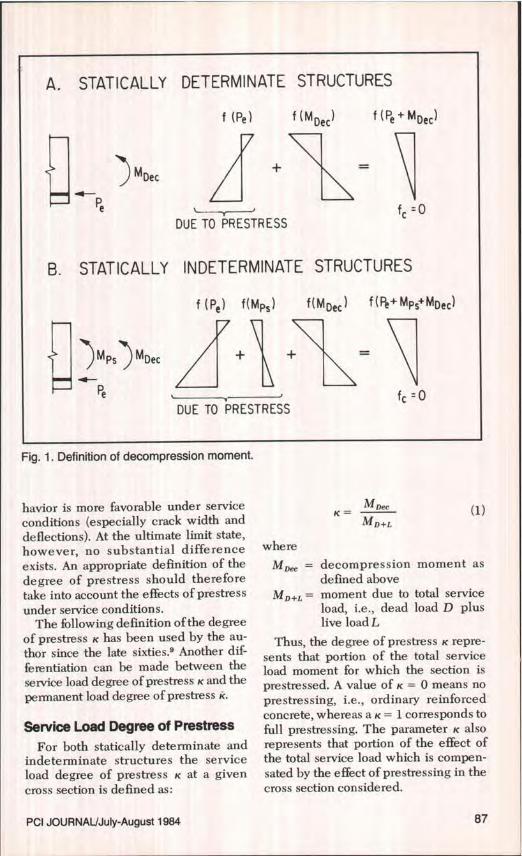
In the third step, the required area of
nonprestressed reinforcement A8 is de-termined from the nominal momentstrength needed (Fig. 2):
M. = Ap fn8Jn + AJ. J8 (4)
and
= M. — Avf j9118
(5)
favis
whereM„ = nominal moment strength at
section needed to fulfill thebasic requirements for strengthdesign. Note that M„ must becalculated with the safety fac-tors of the applied code (loadfactors and resistance factor orcapacity reduction factor), tak-ing into account the estimatedor calculated value of MP8 instatically indeterminate struc-tures (see design example inAppendix A).
fps = specified yield strength of pre-stressed reinforcement
= specified yield strength of non-prestressed reinforcement
j, = internal lever arm from cen-troid of prestressed reinforce-ment to line of action of com-pression force
j$ = internal lever arm from cen-troid of nonprestressed rein-forcement to line of action ofcompression force
With some experience, the location ofthe compression force:
C = APfp. + AB.f^, (6)
90
E N/mm Z N/mm2
a 300 300E
200 200U)U)wcH-
100 100wm
00W 0 50 100 150 200 250 300 mm
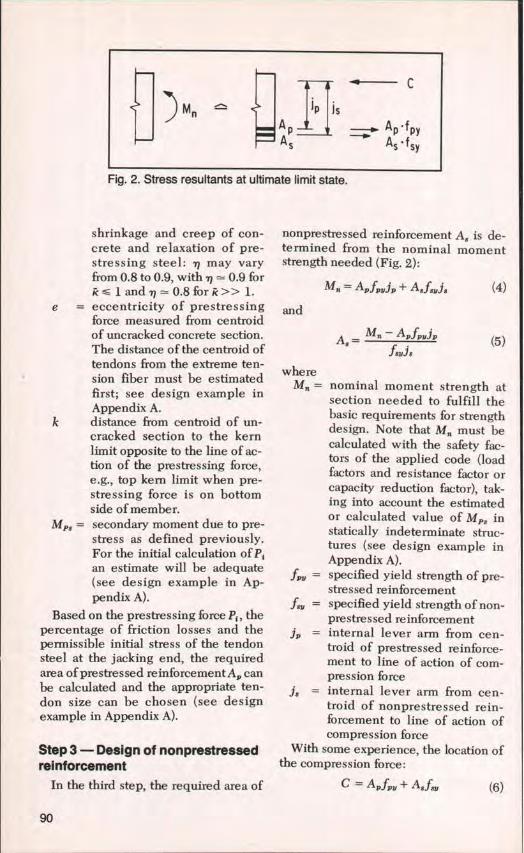
°- BAR SPACING sFig. 3. Reference stress for crack width limitation as a function of spacing ofreinforcement according to Draft Swiss Code SIA 162, August 1983. (Conversionfactors: 100 mm — 4 in., 200 N/mm 2 = 30 ksi.)
BENDINGae /t = 1.0
UNIFORMTENSIONOe/t = 0 0e/t = 0.5
and hence the magnitude of the leverarms of the internal forces, j,, and j3 , canbe estimated with reasonable accuracyor may be calculated by iteration.
Step 4 — Meticulous detailing ofnonprestressed reinforcement
The next, and often last, design stepconcerns the detailing of the nonpre-stressed reinforcement. The followingfactors must be considered:
(a) The closest possible spacing ofbars compatible with the placing of con-crete must be chosen so that under totalservice load, cracks which occur areonly small and well distributed. Closespacing of bars (and in girders also closespacing of stirrups) leads to a narrowmesh of reinforcement near the surface,which significantly improves the qualityof the structure.
(b) Even for high degrees of prestress,
a minimum amount of nonprestressedreinforcement is necessary (see nextmain section in report).
Step 5 — Crack width limitationAn experienced designer will often be
able to detail carefully the nonpre-stressed reinforcement without anyfurther computation. However, forstructures with stringent requirementssome doubt concerning the maximumpermissible bar spacing may arise. Forsuch cases, the following procedure fordetermining the maximum bar spacingfor sufficient crack width limitation maybe followed.
This is based on the new draft of theSwiss Code SIA 162, dated August 1983.The chart in Fig. 3 has been reproducedfrom this draft code. The abscissa givesthe bar spacings (bonded tendons are tobe included, i.e., one tendon corre-
PCI JOURNAUJuIy-August 1984 91
f
• JJN ae = t
s S
-^Islt Jae J
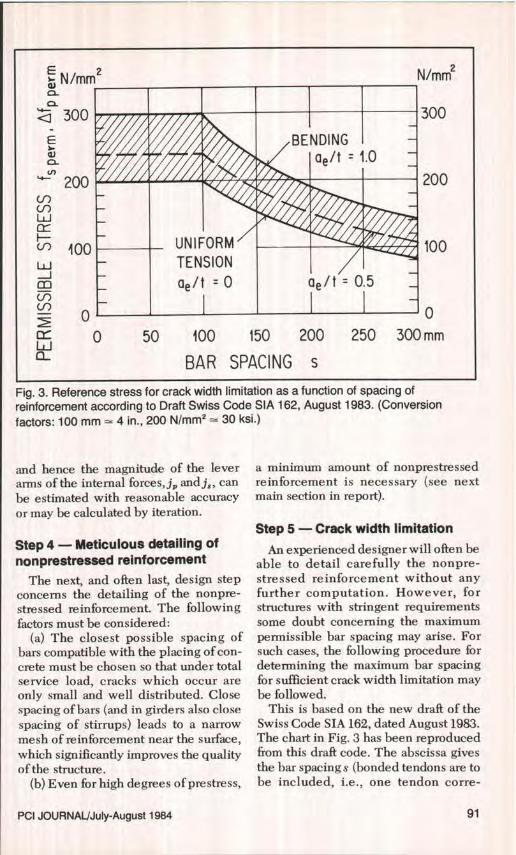
Maximum : ae = 0.20 m
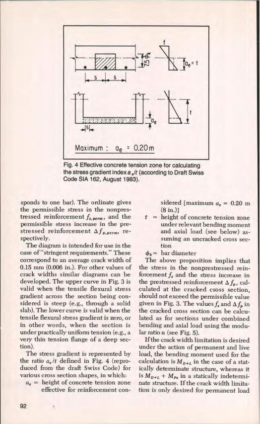
Fig. 4 Effective concrete tension zone for calculatingthe stress gradient index a elt (according to Draft SwissCode SIA 162, August 1983).
sponds to one bar). The ordinate givesthe permissible stress in the nonpres-tressed reinforcement ff,p ,., and thepermissible stress increase in the pre-stressed reinforcement 1 fp,Perm, re-spectively.
The diagram is intended for use in thecase of"stringent requirements." Thesecorrespond to an average crack width of0.15 mm (0.006 in.). For other values ofcrack widths similar diagrams can bedeveloped. The upper curve in Fig. 3 isvalid when the tensile flexural stressgradient across the section being con-sidered is steep (e.g., through a solidslab). The lower curve is valid when thetensile flexural stress gradient is zero, orin other words, when the section isunder practically uniform tension (e.g., avery thin tension flange of a deep sec-tion).
The stress gradient is represented bythe ratio ae It defined in Fig. 4 (repro-duced from the draft Swiss Code) forvarious cross section shapes, in which:
ae = height of concrete tension zoneeffective for reinforcement con-
sidered [maximum a e = 0.20 m(8 in.)]
t = height of concrete tension zoneunder relevant bending momentand axial load (see below) as-suming an uncracked cross sec-tion
Ok = bar diameterThe above proposition implies that
the stress in the nonprestressed rein-forcement f8 and the stress increase inthe prestressed reinforcement A fp , cal-culated at the cracked cross section,should not exceed the permissible valuegiven in Fig. 3. The values f8 and A fp inthe cracked cross section can be calcu-lated as for sections under combinedbending and axial load using the modu-lar ratio n (see Fig. 5).
If the crack width limitation is desiredunder the action of permanent and liveload, the bending moment used for thecalculation is MD+L in the case of a stat-ically determinate structure, whereas itis MD+L + MP8 in a statically indetermi-nate structure. If the crack width limita-tion is only desired for permanent load
92
Pe n • fc
M D+LM D +L .. Pe .. .
Ue
aft-"Pe
fS
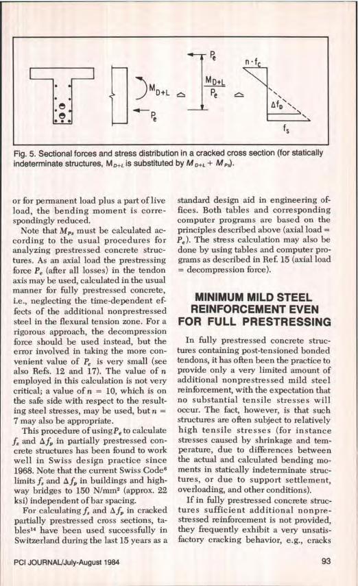
Fig. 5. Sectional forces and stress distribution in a cracked cross section (for statically
indeterminate structures, M D+L is substituted by Mo+L + MPs).
or for permanent load plus a part of liveload, the bending moment is corre-spondingly reduced.
Note that MP8 must be calculated ac-cording to the usual procedures foranalyzing prestressed concrete struc-tures. As an axial load the prestressingforce PQ (after all losses) in the tendonaxis may be used, calculated in the usualmanner for fully prestressed concrete,
i.e., neglecting the time-dependent ef-
fects of the additional nonprestressedsteel in the flexural tension zone. For arigorous approach, the decompressionforce should be used instead, but theerror involved in taking the more con-
venient value of Pe is very small (seealso Refs. 12 and 17). The value of nemployed in this calculation is not verycritical; a value of n = 10, which is onthe safe side with respect to the result-ing steel stresses, may be used, but n =7 may also be appropriate.
This procedure of usingPe to calculatef8 and 4Nf9 in partially prestressed con-crete structures has been found to workwell in Swiss design practice since1968. Note that the current Swiss Codeslimits f8 and A fp in buildings and high-way bridges to 150 N/mm 2 (approx. 22ksi) independent of bar spacing.
For calculating ff and A f,, in crackedpartially prestressed cross sections, ta-b1es 14 have been used successfully inSwitzerland during the last 15 years as a
standard design aid in engineering of-fices. Both tables and correspondingcomputer programs are based on theprinciples described above (axial load =Pe ). The stress calculation may also bedone by using tables and computer pro-grams as described in Ref. 15 (axial load= decompression force).
MINIMUM MILD STEELREINFORCEMENT EVEN
FOR FULL PRESTRESSINGIn fully prestressed concrete struc-
tures containing post-tensioned bondedtendons, it has often been the practice toprovide only a very limited amount ofadditional nonprestressed mild steelreinforcement, with the expectation thatno substantial tensile stresses willoccur. The fact, however, is that suchstructures are often subject to relativelyhigh tensile stresses (for instancestresses caused by shrinkage and tem-perature, due to differences betweenthe actual and calculated bending mo-ments in statically indeterminate struc-tures, or due to support settlement,overloading, and other conditions).
If in fully prestressed concrete struc-tures sufficient additional nonpre-stressed reinforcement is not provided,they frequently exhibit a very unsatis-factory cracking behavior, e.g., cracks
PCI JOURNAL/July-August 1984 93

occur at large spacings and steel elon-gation concentrates at a few cracks.Furthermore, the bending stiffness ofsuch a cracked zone is thus considerablyreduced due to the low total content ofreinforcement.
Partially prestressed structures con-taining a mixture of prestressed andnonprestressed reinforcement, by con-trast, have a larger total area of rein-forcement. This leads to a greaterbending stiffness in the cracked stateand, as a result of the crack distributingeffect of the nonprestressed reinforce-ment, to an improved cracking behavior.Partially prestressed structures, whensubject to tensile stresses, thus exhibitin general a more favorable serviceperformance than analogous morehighly prestressed structures containingrelatively small amounts of nonpre-stressed reinforcement.
It is, therefore, usually preferable in pre-stressed structures to reduce the area ofprestressed reinforcement, i.e., the de-compression moment and degree of pre-stress, respectively, and to incorporate aminimum amount of nonprestressedreinforcement. This steel area may becalculated from the condition that thereinforcement before yielding must beable to resist the tensile force whichwould crack the concrete in the corre-sponding tension zone.
In general, the following rules, basedon the author's experience, can also beused:
(a) The area of the nonprestressedreinforcement must be at least:
Pmtn = 0.3 to 0.4 percent forbending (plates and webs)
Amin = 0.6 to 0.8 percent foruniform tension (tensionflanges)
where
Pmin = AB,min IA,, = ratio of minimumnonprestressed reinforce-ment
As, min = area of minimum nonpres-tressed reinforcement
A, = area of concrete tension zone
effective forA$,m{n (hatched inFig. 4)
The lower values of P., should beused for average quality of concrete withcompressive strengths off,' = 30 N/mm2(4350 psi) and the higher values forhigher quality of concrete with com-pressive strengths of f, = 40 to 50N/mm 2 (5600 to 7250 psi).
(b) The minimum reinforcement mustbe provided as skin reinforcement usingthe closest practicable bar spacing.
(c) In the webs of T-beams and boxgirders, the minimum nonprestressedreinforcement may be concentrated to acertain extent close to the extreme ten-sion fiber.
(d) In sections where the tendons arenot located near the extreme tensionfiber (inclined tendons), the nonpre-stressed longitudinal reinforcement inthe outer tension zone should be de-signed for a tensile force equal to theshear force at the nearest support due todead and live load.19
The above rules apply for post-tensioned structures using bonded ten-dons. For pretensioned members theneed for nonprestressed reinforcementdepends on the bond properties of theprestressing steel, provided that non-prestressed steel is not needed for ulti-mate strength. In the case of well dis-tributed deformed thin wires with a di-ameter up to 7 mm (0.28 in.) as com-monly used in Switzerland, additionalnonprestressed reinforcement is un-necessary. Any cracks which may occurwill be closely spaced, due to the favor-able bond conditions of the deformedwires, and only small crack widths maybe expected under service loads.
DEFLECTION CONTROLFor serviceability, in most cases the
long-term deflection under permanentload is of primary interest, not the de-flection under full live load. Partiallyprestressed structures show a far more
94

favorable long-term deflection behaviorthan either fully prestressed or ordinaryreinforced analogous concrete struc-tures.
Fully prestressed structures oftenshow considerable camber because theyhave been prestressed to compensate fortension due to full live loads. Thiscamber will not develop in partially pre-stressed structures due to the loweroverall prestress. With a judiciouschoice of the degree of prestress, thestress gradient under permanent load,i.e., the difference between top andbottom fiber stresses, can be kept verysmall. Consequently, the long-term de-formations will also be small.
In the large majority of cases met in
practice, the degree of prestress is cho-sen so as to prevent cracking underpermanent load (k , = 0.9). Thus, thelong-term deflections can be calculatedusing the homogeneous section as withfully prestressed concrete.
Only in the few cases of a small de-gree of prestress, when cracking is to beexpected under permanent load, do thecomputational methods of reinforcedconcrete need to be employed, consid-ering combined bending and axial forcein the cracked state. The same applies incalculating elastic deformations underfull design live load when cracking oc-curs.
FATIGUE LOADINGThe stress increases in nonpre-
stressed and prestressed steel due tolive load can on principle be calculatedin the same manner as described in Step5. This calculation is presented in Ref.10 for both k> 1 and R <1. The samepublication discusses the influence ofthe degree of prestress K on the stressincrease in the steel as a function of theratio MDIMD+L.
In Switzerland since 1968 partiallyprestressed buildings and highwaybridges were designed assuming fspef.,n= Of = 150 N/mm 2 (approx. 22 ksi),
calculated for full live load at thecracked cross section. Among all typesof these structures, deck slabs of high-way bridges, partially prestressed in thetransverse direction corresponding to k
1, may be the type of structure mostlikely to be subject to fatigue loading.However, to date no damage due tofatigue is known.
Fatigue tests on concrete beams con-taining a mixture of nonprestressed andprestressed steel 15 have shown that theprestressed steel tends to behave betterthan the nonprestressed steel. Themajority of fatigue failures occurred inthe nonprestressed steel. This leads tothe finding that the fatigue problem ofpartially prestressed concrete is not sig-nificantly different from that of ordinaryreinforced concrete.
On the other hand, fatigue tests onpost-tensioned beams with extremelycurved bonded tendons have shown thatfatigue failure of prestressing wires mayoccur due to friction between the pre-stressed steel and the metal duct prior tothe fatigue failure of the nonprestressedsteel. 1 ' More research on this subjectseems to be needed, including also thedefinition of the fatigue loads.
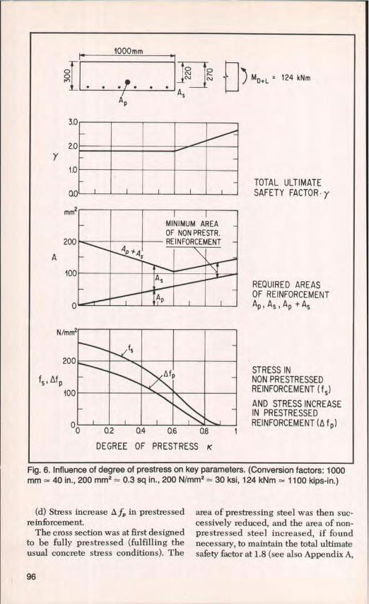
INFLUENCE OFDEGREE OF PRESTRESSThe influence of the degree of pre-
stress on some important parameters isof particular interest. The followingexample is taken from Ref. 10. For arectangular cross section in a staticallydeterminate structure subject to a totalbending moment MD+L , Fig. 6 shows theinfluence of the degree of prestress K onthe following parameters:
(a) Total ultimate safety factor
(y = M n/Mo+c according to SIA 1626).(b) Areas of prestressed reinforcement
A, nonprestressed reinforcement A8,and total reinforcement A,, + A8.
(c) Stress f8 in nonprestressed rein-forcement.
PCI JOURNAL/July-August 1984 95
1000 m m
o^ o ~" MD+L ` 124 kNm• N
A D As
3.0
2.0
1.0TOTAL ULTIMATE
0.0 SAFETY FACTOR-y
mm2
200
A
100REQUIRED AREASOF REINFORCEMENT
0 Ap , A s , A p t As
N/mm2
200STRESS IN
fs , Af pNON PRESTRESSED
100 REINFORCEMENT (fs)
AND STRESS INCREASEIN PRESTRESSED
O REINFORCEMENT (A fp)
0 0.2 0.4 0.6 0.8 1
DEGREE OF PRESTRESS K
MINIMUM AREAOF NON PRESTR.REINFORCEMENT
Ap +Qs
As
AD
fs
^fD
Fig. 6. Influence of degree of prestress on key parameters. (Conversion factors: 1000mm = 40 in., 200 mm 2 — 0.3 sq in., 200 N/mm 2 = 30 ksi, 124 kNm — 1100 kips-in.)
(d) Stress increase 0 f, in prestressedreinforcement.
The cross section was at first designedto be fully prestressed (fulfilling theusual concrete stress conditions). The
area of prestressing steel was then suc-cessively reduced, and the area of non-prestressed steel increased, if foundnecessary, to maintain the total ultimatesafety factor at 1.8 (see also Appendix A,
96

Step 3). The area of nonprestressed steelwas not reduced below a certainminimum. Fatigue loading of the sec-tion was not considered.
It must be noted that the shape of thecurves in Fig. 6 is influenced to a certainextent by the shape of the member crosssection, e.g., for flanged cross sectionsslightly different curves appear. How-ever, the following conclusions drawnfrom the rectangular cross section are ingeneral valid for all cross sections com-monly used:
(a) For high degrees of prestress, thevalue of the ultimate load safety factor isin excess of that required (due to theconcrete stress conditions for K = 1 anddue to the minimum amount of nonpre-stressed steel).
(b) The total quantity of steel attainsits minimum at a certain value of K (K =
0.6 in this example).
(c) The stress in the nonprestressedsteel and the stress increase in the pre-
stressed reinforcement are extremelysmall for higher degrees of prestress (K
> -- 0.7). For medium values (K = 0.4 to0.7), these stresses are still considerablylower than the steel stresses in ordinaryreinforced concrete sections.
In many cases it may be appropriate(see previous section) to choose the areaof prestressing steel Ap and the area ofnonprestressed steel AB so that:
(a) The ultimate safety is not in excessof that required.
(b) A8 is equal to the minimum area ofnonprestressed reinforcement.
This leads to a degree of prestress K,
for which the total amount of steel, Ap +A8 , is a minimum (K = 0.6 in this exam-ple). Higher degrees of prestress aremostly unsuitable.
SAME INITIAL TENDONSTRESS FOR ALL
DEGREES OF PRESTRESSThe behavior of partially prestressed
concrete structures under service loadsdepends primarily on the additionalstrains caused by the stress in the non-prestressed mild steel reinforcementand the stress increase in the pre-stressed reinforcement after crack for-mation.
The absolute value of the stress in theprestressed reinforcement has no influ-ence on the structural behavior underservice loads as long as it is within theelastic limit, a condition usually fulfilledin practice. Safety against the ultimatelimit state is also unaffected, because itis assured by designing the cross sectionas earlier described in Step 3.
The tendons in partially prestressedstructures can therefore be tensionedindependently of the degree of prestressto the same initial value f j or fpj,'e,,,,, re-spectively, as for fully prestressedstructures.
CONCLUSIONSCompared to full prestressing, partial
prestressing of post-tensioned structuresoffers considerably more freedom of de-sign, especially in choosing the size,number, and location of prestressingtendons. Depending on the adoptedarea of prestressing steel, more or lessnonprestressed mild steel reinforce-ment needs to be added to satisfy ulti-mate and serviceability requirements. Itis imperative that a minimum amount ofnonprestressed reinforcement, whichdoes not fall below a certain value, isincorporated into all post-tensionedstructures, even those which are fullyprestressed.
The proposed design method applieswell-known and established design pro-cedures for reinforced or fully pre-stressed structures. The design methodis simple and easily applicable for anydegree of prestress. It allows a smoothtransition from nonprestressed concretethrough partially prestressed concrete tofully prestressed concrete.
PCI JOURNAUJuIy-August 1984 97

REFERENCES1. Emperger, F. v., "Stahlbeton mit vorge-
spannten Zulagen aus hoherwertigemStahl — Forschungsarbeiten auf demGebiete des Eisenbetons" (ReinforcedConcrete with Additions of HighStrength Pretensioned Steel — ResearchStudies in the Field of Reinforced Con-crete), W. Ernst & Sohn, Berlin, 1939.
2. Abeles, P. W., "Fully and Partly Pre-stressed Reinforced Concrete," ACIJournal, Proceedings V. 41, No. 3, Jan-uary 1945, pp. 181-216.
3. Naaman, A. E., and Siriaksorn, A., "Ser-viceability Based Design of PartiallyPrestressed Beams," PCI JOURNAL,V. 24, No. 2, March-April 1979, pp. 64-89.
4. FIP Symposium on Partial Prestressingand Practical Construction in Pre-stressed and Reinforced Concrete, Pro-ceedings, Parts 1 and 2, Bucharest, Ro-mania, September 1980, 708 pp.
5. International Symposium on Non-Lin-earity and Continuity in PrestressedConcrete, Preliminary Publications,University of Waterloo, Waterloo, On-tario, Canada, 1983.
6. SIA 162 (1968), "Norm fur die Bere-chung, Konstruktion and Ausfiihrung vonBauwerken aus Beton, Stahlbeton andSpannbeton" (Code for the Calculation,Detailing and Construction of Structuresof Concrete, Reinforced Concrete andPrestressed Concrete), SchweizerischerIngenieur- and Architekten-Verein(Swiss Engineers' and Architects' As-sociation), Zurich, Switzerland, 1968.
7. Birkenmaier, M., and Jakobsohn, W.,"Das Verhalten von Spannbetonquer-schnitten zwischen Risslast and Bruch-last" (The Behavior of Prestressed Con-crete Cross Sections Between CrackingLoad and Ultimate Load), Schweizer-ische Bauzeitung, V. 77, No. 15, 1959,pp. 218-227.
8. Thurlimann, B., and Caflisch, R., "Teil-weise vorgespannte Bauteile" (PartiallyPrestressed Structural Members), Vor-trage Betontag 1969 (Proceedings of the1969 German Concrete Convention),Deutscher Beton-Verein e.V., Wiesba-den, West Germany, 1969.
9. Bachmann, H., "Versuche an teilweisevorgespannten Leichtbetonbalken unterDauerlast" (Tests on Partially Pre-stressed Lightweight Concrete Beams
Under Permanent Load), Zement andBeton, V. 76, No. 1, 1974, pp. 1-8.
10. Bachmann, H., "Partial Prestressing ofConcrete Structures," IABSE Surveys,S-11/79, International Association ofBridge and Structural Engineering, Zur-ich, Switzerland, November 1979.
11. Bachmann, H., "10 Theses on PartialPrestressing," Proceedings, FIP Sympo-sium on Partial Prestressing and Practi-cal Construction, Bucharest, Romania,September 1980.
12. Bruggeling, A. S. G., "Towards a SimpleMethod of Analysis for Partially Pre-stressed Concrete," Research Report5-82-D 16, Delft University of Technol-ogy, Faculty of Civil Engineering, De-partment of Structural Concrete, Delft,Netherlands, May 1983.
13. Bruggeling, A. S. G., "Partially Pre-stressed Concrete — A Challenge forConcrete Designers." (To be publishedin Sept.-Oct. 1984 PCI JOURNAL).
14. "Tabellen zur Spannungsermittlung inteilweise vorgespannten Stahlbeton-querschnitten" (Tables for Computationof Stresses in Partially Prestressed Con-crete Cross Sections), Stahlton AG, Zur-ich, Switzerland, April 1967.
15. Bennett, E. W., and Joynes, H. W.,"Fatigue Strength of Coldworked Non-prestressed Reinforcement in Pre-stressed Concrete Beams," Magazine ofConcrete Research (London), V. 31,No. 106, March 1979.
16. Tadros, M. K., "Expedient Service LoadAnalysis of Cracked Prestressed Con-crete Sections," PCI JOURNAL, V. 27,No. 6, November-December 1982, pp.86-111.
17. Bachmann, H., Discussion of Reference16, PCI JOURNAL, V. 28, No. 6, No-vember-December 1983, pp. 137-139.
18. Rigon, C., and Thurlimann, B., "FatigueTests on Post-Tensioned ConcreteBeams with Curved Bonded Tendons"(Project Title). To be published.
19. Bachmann, H., "Versuche caber den Ein-fluss geneigter Spannglieder auf dasSchubtragverhalten teilweise vorge-spannter Betonbalken" (Tests on the In-fluence of Inclined Tendons on theShear Behavior of Partially PrestressedConcrete Beams), Der Bauingenieur,V. 51, No. 7, 1976, pp. 251-258.
98
APPENDIX A -DESIGN EXAMPLE
The following design example illus-trates the design method described ear-lier in this paper.
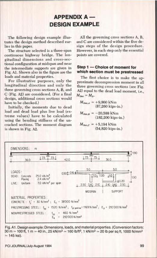
The structure selected is a three-spancontinuous highway bridge. The lon-gitudinal dimensions and cross-sec-tional configuration at midspan and nearthe intermediate supports are given inFig. Al. Shown also in the figure are theloads and material properties.
For illustrative purposes, only thelongitudinal direction and only thethree governing cross sections A, B, andC (Fig. A2) are considered. (For a finaldesign, additional cross sections wouldhave to be checked.)
Initially, the moments due to deadload and dead load plus live load (ex-treme values) have to be calculatedusing the bending stiffness of the un-cracked sections. The moment diagramis shown in Fig. A2.
All the governing cross sections A, B,and C are considered within the five de-sign steps of the design procedure.However, in each step only the essentialpoints are covered.
Step 1 — Choice of moment forwhich section must be prestressed
The first choice is to make the ap-proximate decompression moment in allthree governing cross sections (see Fig.A2) equal to the dead load moment, i.e.,
Mnec = MD.
MoeC,A = + 9,860 kNm(87,260 kips-in.)
MDeC,3 = –20,588 kNm(182,200 kips-in.)
MDeC,c = +5,194 kNm(54,820 kips-in.)
DIMENSIONS: m1.90
75 7.5 7.5751 36.0 7^ 42.0 36.0
LOADS:5.00.30 0.165.0
DEAD: Concrete 25.0 kN/m3 1.0 0.20 10
Paving 2.4 kN/mz 190
LIVE: Uniform 7.0 kN/m 2 per span 40.20
2.50 04 2.f0 i 4
MIDSPAN I SUPPORT
MATERIAL PROPERTIES:CONCRETE : 30 N/mn2 ; E^ = 38000 N/mm2
PRESTRESSING STEEL: fpy = 1520 N/mm 2 ; fpi perm = 1169 N/mm2 ; E p 210000 N/mm2
NONPRESTRESSED STEEL: fsy 460 N/mm2E S = 210000 N/mm2
Fig. Al. Design example: Dimensions, loads, and material properties. (Conversion factors:30 m = 100 ft, 1 m = 40 in., 25 kN/m 3 = 160 lb/ft3 , 1 kN/m 2 – 20 lb per sq ft, 1000 N/mm2= 145 ksi).
PCI JOURNAL/July-August 1984 99

IB —34925a) MDD+L D+L
kNm -20588D /i N8533
C^ 521A 7271 5194
—^ L— 9860 I B 1301718810 C
Al
b) MpS 0.36MPs B MPs,B
Fig. A2. Design example: Moment diagrams. (Note: 10,000 kNm = 90,000 kips-in.)
Thus, all three cross sections wouldbe fully prestressed for permanent loads
(K = 1.0).
Step 2 — Design of prestressedreinforcement
When applying Eq. (3), the secondarymoment due to prestress, MP8 , of which
the general shape is shown in Fig. 8b,must be estimated.
For a continuous beam a proven ini-tial approximation is achieved by taking
MP, to (minus) 30 to 50 percent of thedecompression moment in the supportsection. In this example choose 35 per-cent:
M,,.B = M,,,c = —0.35MDeC.a= 0.35.20,588 kNm= 7,206 kNm
(63,770 kips-in.)
M,, ,A = 0.36 M,,,8 = 0.36 .7,206 kNm= 2,594 kNm
(22,960 kips-in.)
The cross-sectional properties such aslocation of the centroid of section and ofthe kern limit points are given in Fig.A3.
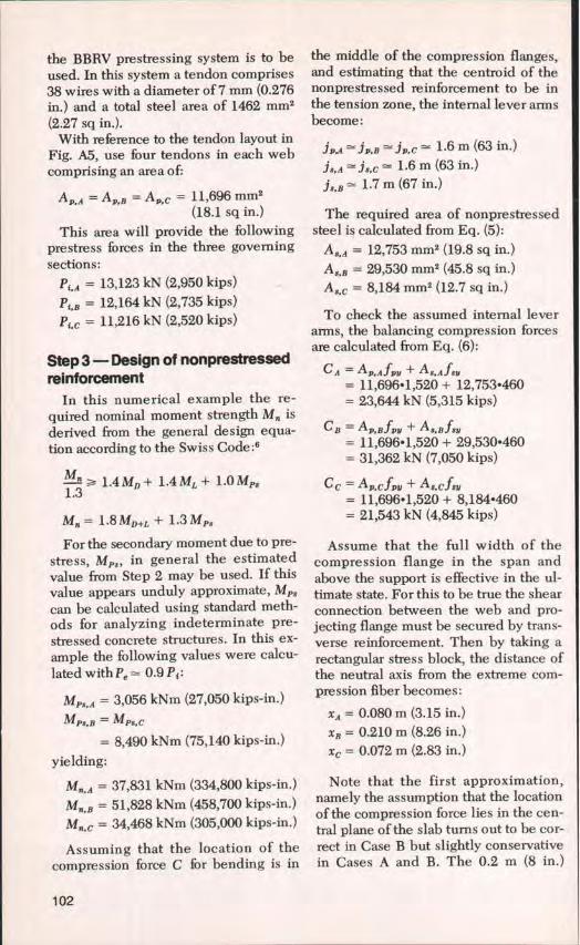
The distance of the centroid of ten-dons in all three sections A, B, C fromthe extreme tension fiber is estimated tobe 0.20 m (8 in.).
Hence, the eccentricity (see Fig. A4)of the prestressing force (absolute value)is:
CA = 1.23 m (48.4 in.)eB = 0.52 m (24.4 in.)
Cc = 1.23 m (48.4 in.)
With 7) = 0.9 the required initial pre-stressing forces become:
1 • 9,860 + 2,594Pt.n =
0.9 1.23 + 0.21
= 9,610 kN (2,160 kips)
1 —20,588 + 7,206P''B = 0.9 • 0.52 + 0.72
= 11,991 kN (2,695 kips)
100
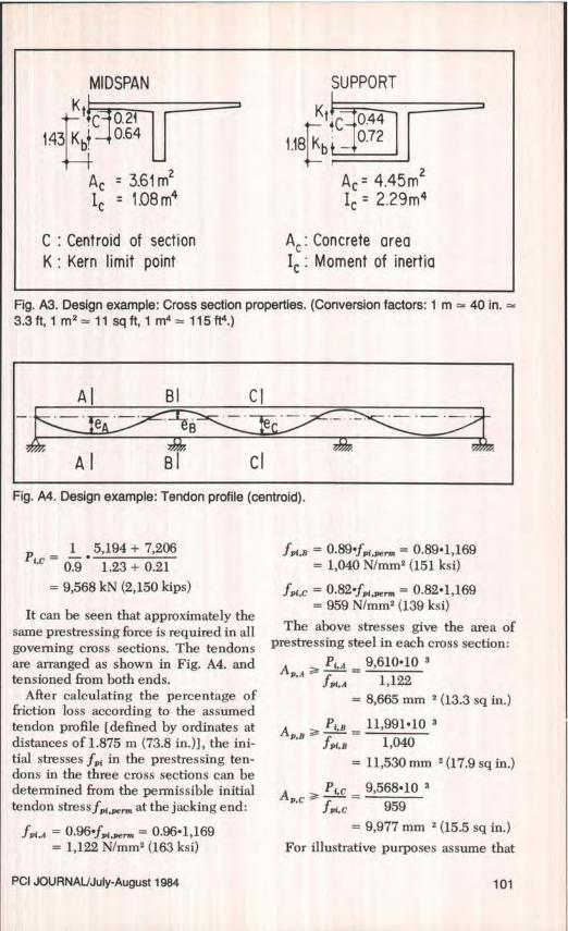
MID SPANKt
C 0.21
143 Kb^ 0.64
A, = 3.61m2I c = 1.08 m4
C : Centroid of sectionK : Kern limit point
SUPPORT
Kt+^ 0.44
1.18 Kb 0.72
A : 4.45m2I C = 2.29m4
A: Concrete areaMoment of inertia
Fig. A3. Design example: Cross section properties. (Conversion factors: 1 m 40 in.3.3 ft, 1 m l 11 sq ft, 1 m4 = 115 ft°.)
Al BI CI
AI BI CI
I Fig. A4. Design example: Tendon profile (centroid).
1 5,194 + 7,206Pi.c =
0.9 1.23+0.21
= 9,568 kN (2,150 kips)
It can be seen that approximately the
same prestressing force is required in allgoverning cross sections. The tendonsare arranged as shown in Fig. A4. andtensioned from both ends.
After calculating the percentage offriction loss according to the assumedtendon profile [defined by ordinates atdistances of 1.875 m (73.8 in.)], the ini-tial stresses ff{ in the prestressing ten-dons in the three cross sections can bedetermined from the permissible initialtendon stress f,,, e ,.,,, at the jacking end:
fm,, = 0.96 fp e ,,,, = 0.96.1,169= 1,122 N/mm 2 (163 ksi)
fm,B = 0.89 f9i pe ,.,,, = 0.89.1,169= 1,040 N/mm 2 (151 ksi)
fm.c = 0.82 fpj,p ,.,„ = 0.82.1,169= 959 N/mm 2 (139 ksi)
The above stresses give the area ofprestressing steel in each cross section:
P,,A 9,610.10AP,A^—=f A 1,122
= 8,665 mm 2 (13.3 sq in.)
pBPt,B _ 11,991.10
A 1,040f^,e= 11,530 mm 2 (17.9 sq in.)
Pic _ 9,568. 10 3
fpi.c 959
= 9,977 mm 2 (15.5 sq in.)
For illustrative purposes assume that
PCI JOURNAL/July-August 1984 101
the BBRV prestressing system is to beused. In this system a tendon comprises38 wires with a diameter of 7 mm (0.276in.) and a total steel area of 1462 mm2(2.27 sq in.).
With reference to the tendon layout inFig. A5, use four tendons in each webcomprising an area of:
Av,A = A D.B = Av,c = 11,696 mm2(18.1 sq in.)
This area will provide the followingprestress forces in the three governing
sections:
Pi,A = 13,123 kN (2,950 kips)
Pi,B = 12,164 kN (2,735 kips)
Pi, c = 11,216 kN (2,520 kips)
the middle of the compression flanges,and estimating that the centroid of thenonprestressed reinforcement to be inthe tension zone, the internal lever armsbecome:
jPA jP,B' JIn.c = 1.6 m (63 in.)
j 8 A j,,c = 1.6 m (63 in.)
j s B 1.7 m (67 in.)
The required area of nonprestressedsteel is calculated from Eq. (5):
AB,A = 12,753 mm 2 (19.8 sq in.)
AS,B = 29,530 mm2 (45.8 sq in.)
A$,c = 8,184 mm2 (12.7 sq in.)
To check the assumed internal leverarms, the balancing compression forcesare calculated from Eq. (6):
Step 3—Design of nonprestressedreinforcement
In this numerical example the re-quired nominal moment strength M. isderived from the general design equa-tion according to the Swiss Code:6
1.4 MD + 1.4ML + 1.0Mg.1.3
M= 1.8 Mo+L + 1.3 Mg.
For the secondary moment due to pre-
stress, Me,, in general the estimatedvalue from Step 2 may be used. If thisvalue appears unduly approximate, MP3
can be calculated using standard meth-ods for analyzing indeterminate pre-stressed concrete structures. In this ex-ample the following values were calcu-
lated with Pe = 0.9 P; :
MPB,A = 3,056 kNm (27,050 kips-in.)
MpS.B = Mrs,c
= 8,490 kNm (75,140 kips-in.)
yielding:
M,, ,A = 37,831 kNm (334,800 kips-in.)
M,, ,B = 51,828 kNm (458,700 kips-in.)
= 34,468 kNm (305,000 kips-in.)
Assuming that the location of thecompression force C for bending is in
C A = AP.AJPY + AS.AfSV= 11,696 • 1,520 + 12,753.460= 23,644 kN (5,315 kips)
CB = Ap,Bfpb + A 3.Bf v= 11,696.1,520 + 29,530.460= 31,362 kN (7,050 kips)
Cc = An.cfvv + AB,c.fsb= 11,696 • 1,520 + 8,184•460= 21,543 kN (4,845 kips)
Assume that the full width of thecompression flange in the span andabove the support is effective in the ul-timate state. For this to be true the shearconnection between the web and pro-jecting flange must be secured by trans-verse reinforcement. Then by taking arectangular stress block, the distance ofthe neutral axis from the extreme com-pression fiber becomes:
xA = 0.080 m (3.15 in.)
XB = 0.210 m (8.26 in.)
xc = 0.072 m (2.83 in.)
Note that the first approximation,namely the assumption that the locationof the compression force lies in the cen-tral plane of the slab turns out to be cor-rect in Case B but slightly conservativein Cases A and B. The 0.2 m (8 in.)
102

thickness of the slab in compressionabove the support is appropriate.
Step 4 — Meticulous detailing ofnonprestressed reinforcement
A possible arrangement of the non-prestressed reinforcement in the threegoverning sections is given in Fig. A5.The reinforcement is at even and narrowspacing distributed along the circumfer-ence of the section. In the tension flangeabove the support the reinforcement re-quired for moment strength is concen-trated towards the web. To secure theparticipation of the longitudinal rein-forcement in the tension flange (by lon-gitudinal shear), transverse reinforce-ment is needed.
The actual chosen nonprestressedreinforcement for moment strengthamounts to:
A,,A = 12,744 mm2 (19.8 sq in.)
A ,g,B = 29,966 mm 2 (46.4 sq in.)
A s,c = 8,338 mm 2 (12.9 sq in.)
In the remaining areas of the sectionsbars 4k 12, s = 150 mm (6.15 in.), areprovided in accordance with the re-quirements for minimum reinforcement.This yields percentages of:
Pmtn = 0.38 percent in the web
Prt„ = 0.75 percent in the tensionflange
I Step 5 — Crack width limitationIn this example it is assumed that
stringent requirements for crack widthlimitation prevail. Therefore, themethod suggested earlier must be fol-lowed including a check for total serviceload.
Using accepted design proceduresand the calculated values of M, fromStep 3, the reduction of the prestressingforces due to losses of creep and shrink-age and relaxation of prestressing steelare calculated with the following re-sults:
F'e.A = 0.85 Pi,A= 11,155 kN (2,510 kips)
PQ,B = 0.91 Pi.,= 11,069 kN (2,490 kips)
Pe.c = 0.93 ',.c= 10,431 kN (2,345 kips)
The stress in the extreme layer of barsof the nonprestressed reinforcement, f3,
and the stress increase in the extremelayer of prestressed reinforcement, s fp,under the action of M D+L, M PS and P e atthe cracked section, are calculated withthe aid of tables. 14 Therefore, it is as-sumed again that the total width of thecompression slab is effective in all threesections. In the tension slab above thesupport (Section B), only the steel arearequired for moment strength is takeninto account.
L .A = 139 N/mm 2 (20.2 ksi)
f..B = 143 N/mm 2 (20.7 ksi)
f8,c = 189 N/mm 2 (27.4 ksi)
fP,A = 130 N/mm 2 (18.9 ksi)
f1,B = 136 N/mm 2 (19.7 ksi)
= 179 N/mm 2 (26.0 ksi)
The permissible stress can be deter-mined using Figs. 3 and 4, and the barspacings given in Fig. A5, from whichthe parameters:
(aelt)A = 0.20 SA = 93 mm (3.7 in.)
(aelt)B = 0.45 SB = 150 mm (5.9 in.)
(aelt)c = 0.19 sc = 140 mm (5.5 in.)
yield the following stresses:
fs.pe ,,A = 220 N/mm 2 (31.9 ksi)
= 175 N/mm 2 (25.4 ksi)
fs,perm.c = 170 N/mm 2 (24.7 ksi)
Note that when comparing f8 within Section C, the permissible steel
stress is slightly exceeded. This minoroverstress could be removed by pro-viding 44k26 bars instead of 30k26 barsin the bottom layer of the reinforcement,resulting in a smaller bar spacing with acorresponding increase of f,,,,m.
I PCI JOURNAL/July-August 1984 103

SECTION -A SECTION C-C
minimum '0k12; s =150
minimumOk12; s =150
150
100e p
required (step 3)12 Ok 26
150$ilQ p required (step 31
160 \ / 160t______7 $k26
rr 4 BBRV 1900 -4`4- 4 BBRV 190093 (4x38 4'k7) 140 (4x38 Ok7)
SECTION B - B
minimum required (ste pIstep 3) minimum
¢ k 12;s=150 Ok20;s =1 50 17¢k26;s=100 $k 20;s=150 k12;s150
'k 12; s 150 8^k20s 150 8^k20—, 50 lk O
k12;s=1504 BBRV 1900 i (minimum)(4x38^k7)
CONVERSIONS (APPROX I MATE)
Reinforcing bars : k12 : #4, 4k 20 = # 6 , 4k 26 = #8
Prestressing wires: 4k 7 = 0.276 in. diameter wireBar spacings : 100 mm = 4 in. , 150 mm = 6 in.
Fig. A5. Design example: Details of prestressed and nonprestressed reinforcement.
Resulting degrees of prestressKnowing the prestressing forces from
Step 5 and the calculated secondarymoments MP3 from Step 3, the resultingdegrees of prestress can be determined:
KA = 0.69 Kg= 0.63 K,= 0.60
KA = 1.32 Kg = 1.08 KC = 1.26
Thus, under the action of permanentloads in the considered cross sections notensile stresses are expected.
Deflection controlThe deflection in the middle of the
side span is computed using standardprocedures. Note that this deflection ishigher than that in the center span.Using an assumed creep factor of 2.0
results in:
—Deflection due to permanentload............+ 58 mm (2.3 in.)
—Deflection due to prestressing- 87 mm (3.4 in.)
Thus, under permanent load condi-tions a camber of 29 mm (1.1 in.) is to beexpected. This is less than r/i000 of the
span length (36 mm), which may be alimit for bridges with regard to aestheticrequirements.
104
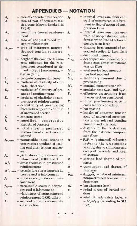
APPENDIX B - NOTATION= area of concrete cross section j, = internal lever arm from cen-
A = area of part of concrete ten- troid of prestressed reinforce-sion zone (shown hatched in ment to line of action of corn-Fig. 4) pression force
A p = area of prestressed reinforce- j 8 = internal lever arm from cen-ment troid of nonprestressed rein-
= area of nonprestressed ten- forcement to line of action ofsion reinforcement compression force
A B,,nin = area of minimum nonpre- k = distance from centroid of un-stressed tension reinforce- cracked section to kern limitment MD = dead load moment
a e = height of the concrete tension MD,C = decompression moment, pro-zone effective for the rein- duces zero stress at extremeforcement considered as de- tension fiberfined in Fig. 4 [maximum a e = MD+L = total service load moment0.20 m (8 in.)] ML = live load moment
C = concrete compression force Mp$ = secondary moment due toE, = modulus of elasticity of con- prestressing
crete (short time) Mn = nominal moment strengthE 9 = modulus of elasticity of pre- n = modular ratio E g/E, and ED/E,
stressed reinforcement Pe = effective prestressing forceE 8 = modulus of elasticity of non- in cross section considered
prestressed reinforcement Pi = initial prestressing force ine = eccentricity of prestressing cross section considered
force with respect to centroid s = bar spacing
of uncracked section t = height of concrete tensionL = concrete stress zone of uncracked cross see-
= specified compressive tion under relevant bending
strength of concrete moment and axial loadfDi = initial stress in prestressed x = distance of the neutral axis
reinforcement at section con- from the extreme compres-sidered sion fiberfpi = permissible initial stress in 7) = PQ/Pi = (estimated) reduction
prestressing tendons at jack- factor to the prestressinging end after tendon anchor- force Pt , due to shrinkage andage creep of concrete and steel
f, = yield stress of prestressed re- relaxation
inforcement (0.002 offset) K = service load degree of pre-L fp = stress increase in prestressed stress
reinforcement
_K = permanent load degree of
0 fP,^,,,, = permissible stress increase in prestressprestressed reinforcement
_
Pmin = As,min/A c = ratio of minimumfy = stress in nonprestressed rein- nonprestressed tension rein-
forcement forcement
f,,, = permissible stress in nonpre- 4k = bar diameter (mm)stressed reinforcement u = radial forces of curved ten-
f„ = yield stress of nonprestressed dons
reinforcement (0.002 offset) y = total ultimate safety factor y= moment of inertia of concrete = Mf/MD+L (according to SIA
cross section 1626).
Copyright © 2022 FDOKUMEN