Hydrogel Dressing with a Nano-Formula against Methicillin ...
at SciVerse ScienceDirect
Biomaterials 33 (2012) 5325e5332
Contents lists available
Biomaterials
journal homepage: www.elsevier .com/locate/biomater ia ls
The integration of 3-D cell printing and mesoscopic fluorescence moleculartomography of vascular constructs within thick hydrogel scaffolds
Lingling Zhao a,1, Vivian K. Lee a,1, Seung-Schik Yoo b, Guohao Dai a,**, Xavier Intes a,*
aDepartment of Biomedical Engineering, Rensselaer Polytechnic Institute, Troy, NY 12180, USAbDepartment of Radiology, Brigham and Women’s Hospital, Harvard Medical School, Boston, MA 02115, USA
a r t i c l e i n f o
Article history:Received 21 February 2012Accepted 1 April 2012Available online 22 April 2012
Keywords:Endothelial cellsCollagen scaffoldPerfused vascular construct3-D cell culture3-D cell printingMesoscopic fluorescence moleculartomography
* Corresponding author. Tel.: þ1 518 276 6964.** Corresponding author.
E-mail addresses: [email protected] (G. Dai), intesx@rp1 Authors contributed equally.
0142-9612/$ e see front matter � 2012 Elsevier Ltd.doi:10.1016/j.biomaterials.2012.04.004
a b s t r a c t
Developing methods that provide adequate vascular perfusion is an important step toward engineeringlarge functional tissues. Meanwhile, an imaging modality to assess the three-dimensional (3-D) struc-tures and functions of the vascular channels is lacking for thick matrices (>2w3 mm). Herein, we reporton an original approach to construct and image 3-D dynamically perfused vascular structures in thickhydrogel scaffolds. In this work, we integrated a robotic 3-D cell printing technology with a mesoscopicfluorescence molecular tomography imaging system, and demonstrated the capability of the platform toconstruct perfused collagen scaffolds with endothelial lining and to image both the fluid flow andfluorescent-labeled living endothelial cells at high-frame rates, with high sensitivity and accuracy. Theseresults establish the potential of integrating both 3-D cell printing and fluorescence mesoscopic imagingfor functional and molecular studies in complex tissue-engineered tissues.
� 2012 Elsevier Ltd. All rights reserved.
1. Introduction
Despite tremendous progresses in the field of tissue engineering[1], there are still significant challenges in creating thick tissueconstructs. Especially, there is a critical need to develop methodsthat provide adequate vascular perfusion for engineering largefunctional tissues [2e4]. Thus, creating a dynamically perfusedvasculature within 3-Dmatrix represents an important step towardthis goal, and this realistic physiologically relevant system allows usto study the growth and maturation process of the tissue-engi-neered thick construct.
However, an imaging modality to assess the 3-D structures andfunctions of the vascular channels is lacking for thicker matrices(>2w3 mm) [5]. Confocal and two-photon microscopes are usefultools for this research, but they can only image tissues with a depthof less than a few hundred microns. The configuration of 3-Dconstruct in the perfusion chamber makes it even more chal-lenging to access the sample for imaging. Another difficulty arisesfrom the scaffold materials, which can be translucent or opaquedepending on the matrix biomaterial and its density, and can
i.edu (X. Intes).
All rights reserved.
become non-transparent as more matrices are produced withtissue growth. This results in optically high-scattering thick tissuesamples. Typically, investigations of engineered tissues mostly relyon histological sections. However, time-consuming procedures andsample fixations make this approach not suitable for high-throughput applications and/or obtaining dynamic information ofliving samples [5]. Thus, it is urgent to develop imaging techniquesthat can image well beyond the penetration limits of conventionalmicroscopy (several hundred microns) to evaluate in real-time thematuration process and functions of thick tissues up to a fewmillimeters.
To fulfill this unmet imaging need, we have developed a fluo-rescence mesoscopic imaging technique based on laminar opticaltomography (LOT) [6] principles. LOT is a non-contact laser scan-ning imaging technique, which harnesses scattered light to probeboth absorbing and fluorescent contrast in living tissues. LOT is ableto obtain depth-resolved 3-D quantitative images to depths ofseveral millimeters with high sensitivity. Similar to fluorescencemolecular tomography (FMT) [7], LOT achieves sensitivity to depth-resolved absorption and fluorescence by exploiting scatteringphotons emerging from the tissue. In FMT, due to larger source-detector (S-D) separation, more uncertainty from scattering lightpropagation though the tissue limits the resolution to macroscopicscale, which makes it difficult to visualize small-diameter engi-neered vasculature. LOT is able to achieve higher resolution thanFMT by shortening S-D separation, thus enabling quantitative and
L. Zhao et al. / Biomaterials 33 (2012) 5325e53325326
non-invasive 3-D imaging for assessing distributions of fluores-cence biomarkers in thick tissues. Conversely to optical coherencetomography (OCT), LOT is sensitive to fluorescence signal whereasOCT is sensitive to index of refraction mismatch [8]. Conversely tophotoacoustic tomography (PAT), LOT allows imaging of genereporters.
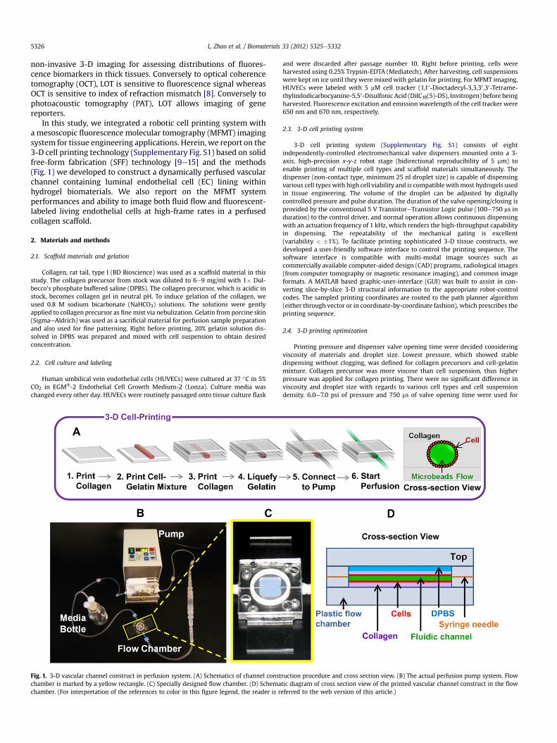
In this study, we integrated a robotic cell printing system witha mesoscopic fluorescence molecular tomography (MFMT) imagingsystem for tissue engineering applications. Herein, we report on the3-D cell printing technology (Supplementary Fig. S1) based on solidfree-form fabrication (SFF) technology [9e15] and the methods(Fig. 1) we developed to construct a dynamically perfused vascularchannel containing luminal endothelial cell (EC) lining withinhydrogel biomaterials. We also report on the MFMT systemperformances and ability to image both fluid flow and fluorescent-labeled living endothelial cells at high-frame rates in a perfusedcollagen scaffold.
2. Materials and methods
2.1. Scaffold materials and gelation
Collagen, rat tail, type I (BD Bioscience) was used as a scaffold material in thisstudy. The collagen precursor from stock was diluted to 6e9 mg/ml with 1� Dul-becco’s phosphate buffered saline (DPBS). The collagen precursor, which is acidic instock, becomes collagen gel in neutral pH. To induce gelation of the collagen, weused 0.8 M sodium bicarbonate (NaHCO3) solutions. The solutions were gentlyapplied to collagen precursor as fine mist via nebulization. Gelatin from porcine skin(SigmaeAldrich) was used as a sacrificial material for perfusion sample preparationand also used for fine patterning. Right before printing, 20% gelatin solution dis-solved in DPBS was prepared and mixed with cell suspension to obtain desiredconcentration.
2.2. Cell culture and labeling
Human umbilical vein endothelial cells (HUVECs) were cultured at 37 �C in 5%CO2 in EGM�-2 Endothelial Cell Growth Medium-2 (Lonza). Culture media waschanged every other day. HUVECs were routinely passaged onto tissue culture flask
Fig. 1. 3-D vascular channel construct in perfusion system. (A) Schematics of channel constchamber is marked by a yellow rectangle. (C) Specially designed flow chamber. (D) Schemachamber. (For interpretation of the references to color in this figure legend, the reader is r
and were discarded after passage number 10. Right before printing, cells wereharvested using 0.25% Trypsin-EDTA (Mediatech). After harvesting, cell suspensionswere kept on ice until they were mixedwith gelatin for printing. For MFMT imaging,HUVECs were labeled with 5 mM cell tracker (1,10-Dioctadecyl-3,3,30 ,30-Tetrame-thylindodicarbocyanine-5,50-Disulfonic Acid (DiIC18(5)-DS), Invitrogen) before beingharvested. Fluorescence excitation and emissionwavelength of the cell tracker were650 nm and 670 nm, respectively.
2.3. 3-D cell printing system
3-D cell printing system (Supplementary Fig. S1) consists of eightindependently-controlled electromechanical valve dispensers mounted onto a 3-axis, high-precision x-y-z robot stage (bidirectional reproducibility of 5 mm) toenable printing of multiple cell types and scaffold materials simultaneously. Thedispenser (non-contact type, minimum 25 nl droplet size) is capable of dispensingvarious cell types with high cell viability and is compatible withmost hydrogels usedin tissue engineering. The volume of the droplet can be adjusted by digitallycontrolled pressure and pulse duration. The duration of the valve opening/closing isprovided by the conventional 5 V TransistoreTransistor Logic pulse (100e750 ms induration) to the control driver, and normal operation allows continuous dispensingwith an actuation frequency of 1 kHz, which renders the high-throughput capabilityin dispensing. The repeatability of the mechanical gating is excellent(variability < �1%). To facilitate printing sophisticated 3-D tissue constructs, wedeveloped a user-friendly software interface to control the printing sequence. Thesoftware interface is compatible with multi-modal image sources such ascommercially available computer-aided design (CAD) programs, radiological images(from computer tomography or magnetic resonance imaging), and common imageformats. A MATLAB based graphic-user-interface (GUI) was built to assist in con-verting slice-by-slice 3-D structural information to the appropriate robot-controlcodes. The sampled printing coordinates are routed to the path planner algorithm(either through vector or in coordinate-by-coordinate fashion), which prescribes theprinting sequence.
2.4. 3-D printing optimization
Printing pressure and dispenser valve opening time were decided consideringviscosity of materials and droplet size. Lowest pressure, which showed stabledispensing without clogging, was defined for collagen precursors and cell-gelatinmixture. Collagen precursor was more viscose than cell suspension, thus higherpressure was applied for collagen printing. There were no significant difference inviscosity and droplet size with regards to various cell types and cell suspensiondensity. 6.0e7.0 psi of pressure and 750 ms of valve opening time were used for
ruction procedure and cross section view. (B) The actual perfusion pump system. Flowtic diagram of cross section view of the printed vascular channel construct in the floweferred to the web version of this article.)
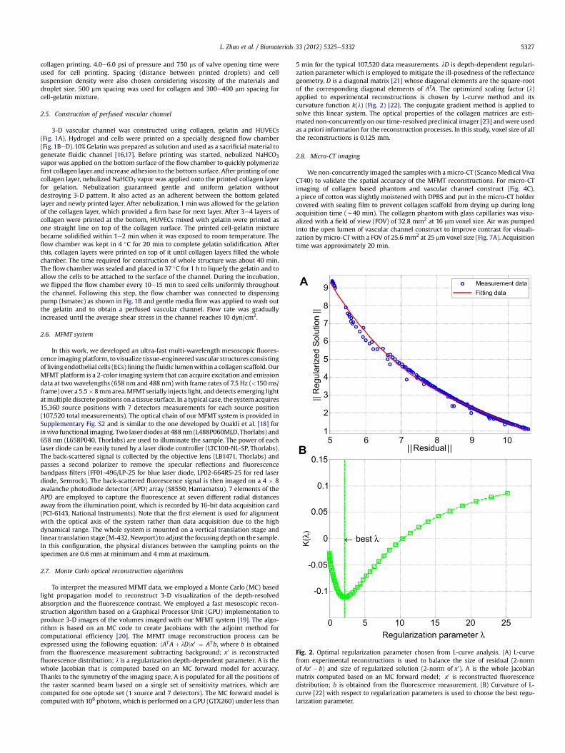
Fig. 2. Optimal regularization parameter chosen from L-curve analysis. (A) L-curvefrom experimental reconstructions is used to balance the size of residual (2-normof Ax0 � b) and size of regularized solution (2-norm of x0). A is the whole Jacobianmatrix computed based on an MC forward model; x0 is reconstructed fluorescencedistribution; b is obtained from the fluorescence measurement. (B) Curvature of L-curve [22] with respect to regularization parameters is used to choose the best regu-larization parameter.
L. Zhao et al. / Biomaterials 33 (2012) 5325e5332 5327
collagen printing. 4.0e6.0 psi of pressure and 750 ms of valve opening time wereused for cell printing. Spacing (distance between printed droplets) and cellsuspension density were also chosen considering viscosity of the materials anddroplet size. 500 mm spacing was used for collagen and 300e400 mm spacing forcell-gelatin mixture.
2.5. Construction of perfused vascular channel
3-D vascular channel was constructed using collagen, gelatin and HUVECs(Fig. 1A). Hydrogel and cells were printed on a specially designed flow chamber(Fig. 1BeD). 10% Gelatinwas prepared as solution and used as a sacrificial material togenerate fluidic channel [16,17]. Before printing was started, nebulized NaHCO3
vapor was applied on the bottom surface of the flow chamber to quickly polymerizefirst collagen layer and increase adhesion to the bottom surface. After printing of onecollagen layer, nebulized NaHCO3 vapor was applied onto the printed collagen layerfor gelation. Nebulization guaranteed gentle and uniform gelation withoutdestroying 3-D pattern. It also acted as an adherent between the bottom gelatedlayer and newly printed layer. After nebulization, 1 minwas allowed for the gelationof the collagen layer, which provided a firm base for next layer. After 3e4 layers ofcollagen were printed at the bottom, HUVECs mixed with gelatin were printed asone straight line on top of the collagen surface. The printed cell-gelatin mixturebecame solidified within 1e2 min when it was exposed to room temperature. Theflow chamber was kept in 4 �C for 20 min to complete gelatin solidification. Afterthis, collagen layers were printed on top of it until collagen layers filled the wholechamber. The time required for construction of whole structure was about 40 min.The flow chamber was sealed and placed in 37 �C for 1 h to liquefy the gelatin and toallow the cells to be attached to the surface of the channel. During the incubation,we flipped the flow chamber every 10e15 min to seed cells uniformly throughoutthe channel. Following this step, the flow chamber was connected to dispensingpump (Ismatec) as shown in Fig. 1B and gentle media flow was applied to wash outthe gelatin and to obtain a perfused vascular channel. Flow rate was graduallyincreased until the average shear stress in the channel reaches 10 dyn/cm2.
2.6. MFMT system
In this work, we developed an ultra-fast multi-wavelength mesoscopic fluores-cence imaging platform, to visualize tissue-engineered vascular structures consistingof living endothelial cells (ECs) lining thefluidic lumenwithin a collagen scaffold. OurMFMT platform is a 2-color imaging system that can acquire excitation and emissiondata at twowavelengths (658 nm and 488 nm) with frame rates of 7.5 Hz (<150 ms/frame) over a 5.5� 8mmarea.MFMTserially injects light, and detects emerging lightatmultiple discrete positions on a tissue surface. In a typical case, the systemacquires15,360 source positions with 7 detectors measurements for each source position(107,520 total measurements). The optical chain of our MFMT system is provided inSupplementary Fig. S2 and is similar to the one developed by Ouakli et al. [18] forin vivo functional imaging. Two laser diodes at 488 nm (L488P060MLD, Thorlabs) and658 nm (L658P040, Thorlabs) are used to illuminate the sample. The power of eachlaser diode can be easily tuned by a laser diode controller (LTC100-NL-SP, Thorlabs).The back-scattered signal is collected by the objective lens (LB1471, Thorlabs) andpasses a second polarizer to remove the specular reflections and fluorescencebandpass filters (FF01-496/LP-25 for blue laser diode, LP02-664RS-25 for red laserdiode, Semrock). The back-scattered fluorescence signal is then imaged on a 4 � 8avalanche photodiode detector (APD) array (S8550, Hamamatsu). 7 elements of theAPD are employed to capture the fluorescence at seven different radial distancesaway from the illumination point, which is recorded by 16-bit data acquisition card(PCI-6143, National Instruments). Note that the first element is used for alignmentwith the optical axis of the system rather than data acquisition due to the highdynamical range. The whole system is mounted on a vertical translation stage andlinear translation stage (M-432, Newport) to adjust the focusing depthon the sample.In this configuration, the physical distances between the sampling points on thespecimen are 0.6 mm at minimum and 4 mm at maximum.
2.7. Monte Carlo optical reconstruction algorithms
To interpret the measured MFMT data, we employed a Monte Carlo (MC) basedlight propagation model to reconstruct 3-D visualization of the depth-resolvedabsorption and the fluorescence contrast. We employed a fast mesoscopic recon-struction algorithm based on a Graphical Processor Unit (GPU) implementation toproduce 3-D images of the volumes imaged with our MFMT system [19]. The algo-rithm is based on an MC code to create Jacobians with the adjoint method forcomputational efficiency [20]. The MFMT image reconstruction process can beexpressed using the following equation: ðATAþ lDÞx0 ¼ ATb, where b is obtainedfrom the fluorescence measurement subtracting background; x0 is reconstructedfluorescence distribution; l is a regularization depth-dependent parameter. A is thewhole Jacobian that is computed based on an MC forward model for accuracy.Thanks to the symmetry of the imaging space, A is populated for all the positions ofthe raster scanned beam based on a single set of sensitivity matrices, which arecomputed for one optode set (1 source and 7 detectors). The MC forward model iscomputed with 106 photons, which is performed on a GPU (GTX260) under less than
5 min for the typical 107,520 data measurements. lD is depth-dependent regulari-zation parameter which is employed to mitigate the ill-posedness of the reflectancegeometry. D is a diagonal matrix [21] whose diagonal elements are the square-rootof the corresponding diagonal elements of ATA. The optimized scaling factor (l)applied to experimental reconstructions is chosen by L-curve method and itscurvature function k(l) (Fig. 2) [22]. The conjugate gradient method is applied tosolve this linear system. The optical properties of the collagen matrices are esti-mated non-concurrently on our time-resolved preclinical imager [23] andwere usedas a priori information for the reconstruction processes. In this study, voxel size of allthe reconstructions is 0.125 mm.
2.8. Micro-CT imaging
We non-concurrently imaged the samples with a micro-CT (ScancoMedical VivaCT40) to validate the spatial accuracy of the MFMT reconstructions. For micro-CTimaging of collagen based phantom and vascular channel construct (Fig. 4C),a piece of cotton was slightly moistened with DPBS and put in the micro-CT holdercovered with sealing film to prevent collagen scaffold from drying up during longacquisition time (w40 min). The collagen phantom with glass capillaries was visu-alized with a field of view (FOV) of 32.8 mm2 at 16 mm voxel size. Air was pumpedinto the open lumen of vascular channel construct to improve contrast for visuali-zation by micro-CT with a FOV of 25.6 mm2 at 25 mmvoxel size (Fig. 7A). Acquisitiontime was approximately 20 min.
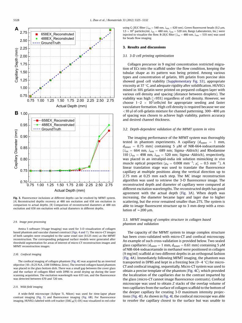
Fig. 3. Fluorescence inclusions at different depths can be resolved by MFMT system.(A) Reconstructed depths recovery at 488 nm excitation and 658 nm excitation incomparison to actual depths. (B) Comparison of reconstructed diameters at 488 nmexcitation and 658 nm excitation with actual diameters in different depths.
L. Zhao et al. / Biomaterials 33 (2012) 5325e53325328
2.9. Image post-processing
Amira 5 software (Visage Imaging) was used for 3-D visualization of collagenbased phantom and vascular channel construct (Figs. 4 and 7). The micro-CT imagesof both samples were resampled to the same voxel size (0.125 mm) as the MFMTreconstruction. The corresponding polygonal surface models were generated afterthreshold segmentation for areas of interest of micro-CT reconstruction images andMFMT reconstruction images.
2.10. Confocal imaging
The confocal imaging of collagen phantom (Fig. 4I) was acquired by an invertedobjective (10�/0.25 N.A., LSM 510Meta; Zeiss). The inverted collagen based phantomwas placed in the glass bottom dish. There was a small gap between the cover glassand the surface of collagen filled with DPBS to avoid drying up during the laserscanning acquisition. The excitation wavelength was 633 nm, and the fluorescencewas detected between 670 and 720 nm.
2.11. Wild-field imaging
A wide-field microscope (Eclipse Ti, Nikon) was used for time-lapse phasecontrast imaging (Fig. 5) and fluorescence imaging (Fig. 6B). For fluorescenceimaging, HUVECs labeled with cell tracker (DiIC18(5)-DS) was visualized in red color
using G-2E/C filter (lex ¼ 540 nm, lem ¼ 620 nm). Green fluorescent beads (0.2 mm,1.5 � 105 particles/ml, lex ¼ 480 nm, lem ¼ 520 nm, Bangs Laboratories, Inc.) wereinjected to visualize the flow. B-2E/C filter (lex ¼ 480 nm, lem ¼ 535 nm) was usedfor beads flow imaging.
3. Results and discussions
3.1. 3-D cell printing optimization
Collagen precursor in 9 mg/ml concentration restricted migra-tion of ECs into the scaffold under the flow condition, keeping thetubular shape as its pattern was being printed. Among varioustypes and concentration of gelatin, 10% gelatin from porcine skinshowed good cell viability (Supplementary Fig. S3), appropriateviscosity at 37 �C, and adequate rigidity after solidification. HUVECsmixed in 10% gelatin were printed on prepared collagen layer withvarious cell density and spacing (distance between droplets). Theviability was high (>95%) regardless of cell density. However, wechoose 1e2 � 107cells/ml for appropriate seeding and fastervasculature formation. High cell density is required because we use<10 ml of cell-gelatin mixture for channel patterning. 300e400 mmof spacing was chosen to achieve high viability, pattern accuracyand desired channel thickness.
3.2. Depth-dependent validation of the MFMT system in vitro
The imaging performance of the MFMT system was thoroughlytested in phantom experiments. A capillary (douter ¼ 1 mm,dinner ¼ 0.75 mm) containing 5 mM of NIR-664-iodoacetamide(lex ¼ 664 nm, lem ¼ 689 nm; SigmaeAldrich) and Rhodamine110 (lex ¼ 498 nm, lem ¼ 520 nm; SigmaeAldrich), respectively,was placed in an intralipid-india ink solution mimicking in vivomuscle optical properties (ma ¼ 0.008 mm�1; m0s ¼ 0.5 mm�1). Alinear translation stage was used to translate the fluorescencecapillary at multiple positions along the vertical direction up to2.75 mm at 0.25 mm each step. The MC image reconstructionalgorithm was used to retrieve the 3-D fluorescence image. Thereconstructed depth and diameter of capillary were compared atdifferent excitationwavelengths. The reconstructed depth has goodagreement with the actual depth (Fig. 3A). When depth wasincreasing, the diameter became lager and lager due to higherscattering, but the error remained smaller than 27%. The system isable to image fluorescent structure up to 3 mm deep with a reso-lution of w200 mm.
3.3. MFMT imaging of complex structure in collagen basedphantom and validation
The capacity of the MFMT system to image complex structurehas been cross-validated with micro-CT and confocal microscopy.An example of such cross-validation is provided below. Two sealedglass capillaries (douter ¼ 1 mm, dinner ¼ 0.61 mm) containing 5 mMof NIR-664-iodoacetamide inmethanol were positioned in collagen(9 mg/ml) scaffold at two different depths in an orthogonal fashion(Fig. 4A). Immediately following MFMT imaging, the phantom wastransported in DPBS and kept in a freezing box (0e4 �C) for micro-CT and confocal imaging, sequentially. Micro-CT systemwas used toobtain a precise template of the phantom (Fig. 4C), which providedthe localization of the capillaries due to the contrast imparted bythe glass (micro-CT cannot image fluorescence contrasts). Confocalmicroscope was used to obtain Z stacks of the overlap volume oftwo capillaries from the surface of collagen scaffold to the bottom ofthe deeper capillary for creating 3-D maximum intensity projec-tions (Fig. 4I). As shown in Fig. 4I, the confocal microscope was ableto resolve the capillary closest to the surface but was unable to
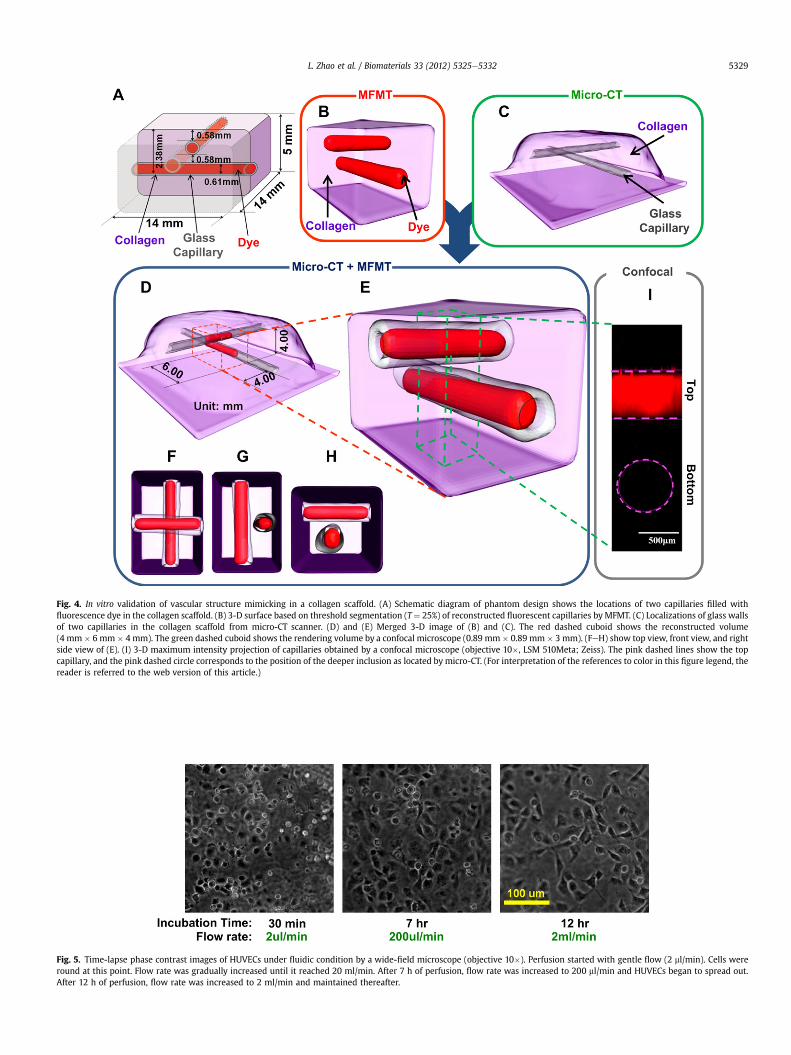
Fig. 4. In vitro validation of vascular structure mimicking in a collagen scaffold. (A) Schematic diagram of phantom design shows the locations of two capillaries filled withfluorescence dye in the collagen scaffold. (B) 3-D surface based on threshold segmentation (T ¼ 25%) of reconstructed fluorescent capillaries by MFMT. (C) Localizations of glass wallsof two capillaries in the collagen scaffold from micro-CT scanner. (D) and (E) Merged 3-D image of (B) and (C). The red dashed cuboid shows the reconstructed volume(4 mm � 6 mm � 4 mm). The green dashed cuboid shows the rendering volume by a confocal microscope (0.89 mm � 0.89 mm � 3 mm). (FeH) show top view, front view, and rightside view of (E). (I) 3-D maximum intensity projection of capillaries obtained by a confocal microscope (objective 10�, LSM 510Meta; Zeiss). The pink dashed lines show the topcapillary, and the pink dashed circle corresponds to the position of the deeper inclusion as located by micro-CT. (For interpretation of the references to color in this figure legend, thereader is referred to the web version of this article.)
Fig. 5. Time-lapse phase contrast images of HUVECs under fluidic condition by a wide-field microscope (objective 10�). Perfusion started with gentle flow (2 ml/min). Cells wereround at this point. Flow rate was gradually increased until it reached 20 ml/min. After 7 h of perfusion, flow rate was increased to 200 ml/min and HUVECs began to spread out.After 12 h of perfusion, flow rate was increased to 2 ml/min and maintained thereafter.
L. Zhao et al. / Biomaterials 33 (2012) 5325e5332 5329
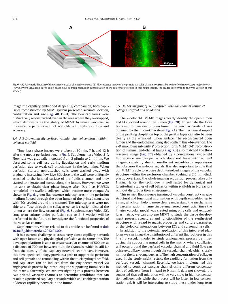
Fig. 6. (A) Schematic diagram of the printed vascular channel construct. (B) Fluorescence image of the printed vascular channel construct by a wide-field microscope (objective 4�).HUVECs were visualized in red color, beads flow in green color. (For interpretation of the references to color in this figure legend, the reader is referred to the web version of thisarticle.)
L. Zhao et al. / Biomaterials 33 (2012) 5325e53325330
image the capillary embedded deeper. By comparison, both capil-laries reconstructed by MFMT system presented accurate location,configuration and size (Fig. 4B, DeH). The two capillaries weredistinctively reconstructed even in the areawhere they overlapped,which demonstrates the ability of MFMT to image vascular-likefluorescence patterns in thick scaffolds with high-resolution andaccuracy.
3.4. A 3-D dynamically perfused vascular channel construct withincollagen scaffold
Time-lapse phase images were taken at 30 min, 7 h, and 12 hafter the media perfusion began (Fig. 5, Supplementary Video S1).Flow rate was gradually increased from 2 ml/min to 2 ml/min. Weobserved some cell loss during liquefaction and early mediumperfusion due to weak cell attachment in the beginning. Whenperfusion started, non-attached cells were washed away withgradually increasing flow. Live ECs close to the wall were uniformlyattached to the luminal surface of the fluidic channel, and theystarted to migrate and spread along the lumen. However, we werenot able to obtain clear phase images after Day 1 as HUVECsremodeled the scaffold collagen, which became more opaque. Asshown in Fig. 6, green fluorescence microspheres in the perfusionmedium flowed through the open lumen of the printed structureswith ECs seeded around the channel. The microspheres were notable to diffuse through the collagen gel so it clearly indicated thelumen where the flow occurred (Fig. 6, Supplementary Video S2).Long-term culture under perfusion (up to 2e3 weeks) will beperformed in the future to investigate the functional properties ofthe vascular channel.
Supplementary videos related to this article can be found at doi:10.1016/j.biomaterials.2012.04.004.
It is a current challenge to create very dense capillary networkwith open lumen and physiological perfusion at the same time. Thedeveloped platform is able to create vascular channel of 500 mm ata distance of 700 mm between multiple channels, which is still farfrom the density of the capillary network seen in vivo. However,this developed technology provides a path to support the perfusionand cell growth and remodeling within the thick hydrogel scaffold,and capillaries can be induced from the engineered vessel viaangiogenesis process by introducing the supporting mural cells inthe matrix. Currently, we are investigating this process betweentwo printed vascular channels to determine conditions that canresult in a perfused capillary network, whichwill enable generationof denser capillary network in the future.
3.5. MFMT imaging of 3-D perfused vascular channel constructcollagen scaffold and validation
The 2-color 3-D MFMT images clearly identify the open lumenand ECs located around the lumen (Fig. 7B). To validate the loca-tions and dimensions of open lumen, the vascular construct wasobtained by the micro-CT system (Fig. 7A). The mechanical impactof the printing droplet on top of the gelatin layer can also be seenclearly as the wrinkled lumen surface. The reconstructed openlumen and the endothelial lining also confirm this observation. The2-D maximum intensity Z projection form MFMT 3-D reconstruc-tion of luminal endothelial lining (Fig. 7D) also matched the fluo-rescence image (Fig. 7C) obtained by a conventional wide-fieldfluorescence microscope, which does not have intrinsic 3-Dimaging capability due to insufficient out-of-focus suppressionthat obscures the in-focus signals. It is also important to note thatour MFMT is able to acquire depth-resolved images of the vascularstructure within the perfusion chamber (behind a 2.5 mm-thickplastic cover), and thewhole imaging acquisition process takes only1 min. Hence, the technique is well suited for dynamical andlongitudinal studies of cell behavior within scaffolds in bioreactorswithout disturbing their environment.
This in vitro fluorescence imaging of vascular construct can givestructural and functional information with depth embedded up to3 mm, which can help to more clearly understand the mechanismsof vascularization in large tissue-engineered constructs. Since thein vitro vascular model was created using only cells and extracel-lular matrix, we can also use MFMT to study the tissue develop-ment process, structures and functionalities of the synthesizedstructure with regard to matrix properties and culture parameter,or the biological interactions between ECs and surrounding cells.
In addition to the potential application of this integrated plat-form, we can image the distribution of different fluorophores in thisin vitro vascular model to study angiogenesis process by intro-ducing the supporting mural cells in the matrix, where capillarieswill occur around the perfused vascular channel and fluid flow canachieve capillary lumen though the vascular channel, which closelymimics the in vivo angiogenesis. The high concentration of collagenused in the study might restrict the capillary formation from theperfused vascular channel. Recently, we have implemented thismethod to construct vascular channel using different concentra-tions of collagen (from 3 mg/ml to 9 mg/ml, data not shown). It issuggested that cell migration will be very slow in high concentra-tion collagen gels while the process will be faster in low concen-tration gel. It will be interesting to study these under long-term

Fig. 7. Imaging of 3-D perfused vascular channel construct in a thick collagen scaffold. (A) Localizations and dimensions of the open lumen from a micro-CT scanner. (B) 3-D surfacerendering based on threshold segmentation (T ¼ 35%) from MFMT image reconstructions of open lumen (green) and luminal endothelial lining (red). (C) Fluorescence image ofluminal endothelial lining in the printed vascular channel by a wide-field microscope (objective 4�). (D) 2-D maximum intensity Z projection of MFMT reconstruction of luminalendothelial lining. Scale: 1 mm. (E) Merged 3-D image of (A) and (B). The reconstructed volume is marked by the blue dashed cuboid (2.5 mm � 7 mm � 3 mm). (F) Merged 3-Dimage of reconstructed open lumen and (A). (GeJ) are top view and right side view of (E) and (F), respectively. (For interpretation of the references to color in this figure legend, thereader is referred to the web version of this article.)
L. Zhao et al. / Biomaterials 33 (2012) 5325e5332 5331
(2e3 weeks) perfused condition. Ongoing studies in the lab willinvestigate the functional properties of the vascular channel andcapillary formation at different gel density. Although muchresearch remains to be done, it appears that this technique hasa great potential to bridge the gap between vascularization andtissue regeneration, and thus facilitate clinical applications oftissue-engineered constructs. The distribution and intensity offluorescence may provide an insight into the sequence of eventsthat leads to angiogenesis process and may help elucidate vascu-larization mechanisms.
The unique advantages of the 3-D cell printing and fluorescencemesoscopic imaging system will make this integrated platforma new and important tool in the field of tissue engineering. It willallow us to construct and study tissue structures that are previously
unachievable with other technologies. For example, it can be usedto construct complex 3-D tissue structures containing multiple celltypes with vasculature, as well as to study molecular expressionand the dynamic interactions of cellular/tissue processessurrounding the vascular perfusion in engineered thick tissues.Further development of this integrated platform promises to bringsignificant value to functional tissue engineering.
4. Conclusion
In this study, we developed an integrated platform bycombining the 3-D cell printing technique with MFMT system. Ourresults demonstrated the capability of cell printing technology tocreate in vitro vascular tissues with perfusion, and to allow rapid,

L. Zhao et al. / Biomaterials 33 (2012) 5325e53325332
non-contact imaging of live tissue up to a fewmillimeters in depth.The 3-D cell printing system is able to dispense live cells, solublefactors, and phase-changing hydrogel in desired pattern main-taining high cell viability. ECs were incorporated to from the innerlining of the vascular construct, since ECs can regulate permeabilityand form lumens as well as remodel of vascular networks, allowtissue growth and regeneration for our future study. We alsodeveloped an MFMT system to investigate the function and struc-ture of vascular construct. The two-color MFMT system is able toacquire quantitative 3-D absorption and fluorescence contrasts ofthick tissues (up to 3 mm) with high-frame rates of 7.5 Hz over anadaptable large FOV (5.5 � 8 mm at maximum). Meanwhile, a fastMCmethod based algorithmwas also developed to reconstruct 3-Dfluorescence distribution of imaged volume.
Author contributions
G.D. and X.I. conceived and initiated project. S-S.Y. and V.K.L.designed the 3-D bio-fabrication technology. X.I. and L.Z. developedthe MFMT system. L.Z. and V.K.L. designed and performed experi-ments, analyzed data and wrote the manuscript. G.D. and X.I.supervised the project.
Competing financial interests
The authors declare no competing financial interests.
Acknowledgments
We thank N. Ouakli, E. Guevara, and F. Lesage (Ecole Poly-technique Montreal, Canada) for help with integrating MFMTsystem and funding support from National Institutes of HealthR21HL102773.
Appendix A. Supplementary material
Supplementarymaterials associatedwith this article canbe found,in the online version, at doi:10.1016/j.biomaterials.2012.04.004.
References
[1] Khademhosseini A, Vacanti JP, Langer R. Progress in tissue engineering. Sci Am2009;300:64e71.
[2] Griffith LG, Swartz MA. Capturing complex 3D tissue physiology in vitro. NatRev Mol Cell Biol 2006;7:211e24.
[3] Jain RK, Au P, Tam J, Duda DG, Fukumura D. Engineering vascularized tissue.Nat Biotechnol 2005;23:821e3.
[4] Lovett M, Lee K, Edwards A, Kaplan DL. Vascularization strategies for tissueengineering. Tissue Eng Part B Rev 2009;15:353e70.
[5] Ntziachristos V. Going deeper than microscopy: the optical imaging frontier inbiology. Nat Methods 2010;7:603e14.
[6] Hillman EM, Burgess SA. Sub-millimeter resolution 3D optical imaging ofliving tissue using laminar optical tomography. Laser Photon Rev 2009;3:159e79.
[7] Ntziachristos V. Fluorescence molecular imaging. Annu Rev Biomed Eng 2006;8:1e33.
[8] Huang D, Swanson EA, Lin CP, Schuman JS, StinsonWG, Chang W, et al. Opticalcoherence tomography. Science 1991;254:1178e81.
[9] Sun W, Darling A, Starly B, Nam J. Computer-aided tissue engineering:overview, scope and challenges. Biotechnol Appl Biochem 2004;39:29e47.
[10] Borenstein JT, Weinberg EJ, Orrick BK, Sundback C, Kaazempur-Mofrad MR,Vacanti JP. Microfabrication of three-dimensional engineered scaffolds. TissueEng 2007;13:1837e44.
[11] Norotte C, Marga FS, Niklason LE, Forgacs G. Scaffold-free vascular tissueengineering using bioprinting. Biomaterials 2009;30:5910e7.
[12] Mironov V, Trusk T, Kasyanov V, Little S, Swaja R, Markwald R. Biofabrication:a 21st century manufacturing paradigm. Biofabrication 2009;1:022001.
[13] Mironov V, Boland T, Trusk T, Forgacs G, Markwald RR. Organ printing:computer-aided jet-based 3D tissue engineering. Trends Biotechnol 2003;21:157e61.
[14] Lee W, Debasitis JC, Lee VK, Lee J-H, Fischer K, Edminster K, et al.Multi-layered culture of human skin fibroblasts and keratinocytesthrough three-dimensional freeform fabrication. Biomaterials 2009;30:1587e95.
[15] Lee W, Lee V, Polio S, Keegan P, Lee J-H, Fischer K, et al. On-demand three-dimensional freeform fabrication of multi-layered hydrogel scaffold withfluidic channels. Biotechnol Bioeng 2010;105:1178e86.
[16] Golden AP, Tien J. Fabrication of microfluidic hydrogels using molded gelatinas a sacrificial element. Lab Chip 2007;7:720e5.
[17] Boland T, Xu T, Damon B, Cui X. Application of inkjet printing to tissueengineering. Biotechnol J 2006;1:910e7.
[18] Ouakli N, Guevara E, Dubeau S, Beaumont E, Lesage F. Laminar opticaltomography of the hemodynamic response in the lumbar spinal cord of rats.Optic Express 2010;18:10068e77.
[19] Fang QQ, Boas DA. Monte Carlo simulation of photon migration in 3D turbidmedia accelerated by graphics processing units. Opt Express 2009;17:20178e90.
[20] Chen J, Intes X. Comparison of Monte Carlo methods for fluorescencemolecular tomography computational efficiency. Med Phy 2011;38(10).
[21] Endoh R, Fujii M, Nakayama K. Depth-adaptive regularized reconstruction forreflection diffuse optical tomography. Opt Rev 2008;15:51e6.
[22] Intes X, Ripoll J, Chen Y, Nioka S, Yodh AG, Chance B. In vivo continuous-waveoptical breast imaging enhanced with indocyanine green. Med Phys 2003;30:1039e47.
[23] Venugopal V, Chen J, Intes X. Development of an optical imaging platform forfunctional imaging of small animals using wide-field excitation. Biomed OptExpress 2010;1:143e56.
Copyright © 2022 FDOKUMEN